
- Manuals
- Brands
- Nice Manuals
- Control Unit
- MC800
- Instructions and warnings for installation and use
-
Contents
-
Table of Contents
-
Troubleshooting
-
Bookmarks
Quick Links
Nice
MC800
Control unit
EN — Instructions and warnings for installation and use
Related Manuals for Nice MC800
Summary of Contents for Nice MC800
-
Page 1
Nice MC800 Control unit EN — Instructions and warnings for installation and use… -
Page 2: Table Of Contents
ENGLISH GENERAL SAFETY WARNINGS AND PRECAUTIONS Translation of the original instructions in full GENERAL SAFETY WARNINGS AND PRECAUTIONS WARNING! Important safety instructions. Observe all the instructions as improper installation may cause serious damages. CONTENTS WARNING! Important safety instructions. It is im- portant to comply with these instructions to ensure personal safety.
-
Page 3: Product Description And Intended Use
PRODUCT DESCRIPTION AND INTENDED USE MC800 is an electronic control unit for automating swing gates. The control unit is specially configured for being connected to PRODUCT DESCRIPTION AND INTENDED USE devices belonging to the Opera System and to the Bluebus system. Other available accessories include receivers configured with “SM”…
-
Page 4: Installation
Before proceeding with the installation, prepare the The automation made by using MC800 must have required electrical cables by referring to “Figure 4” sensitive edges. and to that stated in the “TECHNICAL SPECIFICA- TIONS”…
-
Page 5: Installing The Control Unit
The electrical connection of the various devices present on the automation (photocells, digital keypads, transponder card readers, etc.) to the control unit must be made through the Nice “Bluebus” system. For the other connections, refer to that spec- ified below.
-
Page 6: Wiring Diagram And Description Of Connections
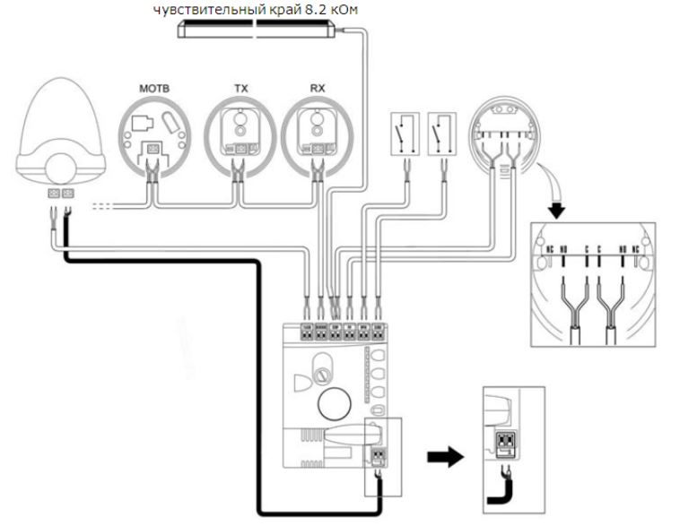
4.2 WIRING DIAGRAM AND DESCRIPTION OF CONNECTIONS 4.2.1 Wiring diagram 6 – ENGLISH…
-
Page 7: Wiring Diagram With Relay Photocells Without Phototest
4.2.2 Wiring diagram with relay photocells without phototest ENGLISH – 7…
-
Page 8: Wiring Diagram With Relay Photocells With Phototest
4.2.3 Wiring diagram with relay photocells with phototest 8 – ENGLISH…
-
Page 9: Description Of Connections
4.2.4 Description of connections The meaning of the codes/wording stamped on the electronic board near the relative terminals is described below. Table 2 ELECTRICAL CONNECTIONS Terminals Function Description Cable type 120/230 V ~ 50/60 Mains power supply 3 x 1.5 mm Hz power supply Warning light: 120/230 V ~ 50/60…
-
Page 10: Operations For Connection
4.2.5 Operations for connection 4.4 ADDRESSING OF DEVICES CONNECTED WITH THE BLUEBUS SYSTEM To make the electrical connections (“Figure 7”): remove the terminals from their housings To allow the control unit to recognise the devices connected connect the various devices to the relevant terminals ac- through the “BlueBUS”…
-
Page 11: Initial Start-Up And Electrical Connections Test
4.5 INITIAL START-UP AND ELECTRICAL 4.6 LEARNING OF CONNECTED DEVICES CONNECTIONS TEST After the initial start-up, the control unit must recognise the de- After powering the control unit, carry out the following checks vices connected to the “Bluebus” and “Stop” inputs. (“Figure 12”): The control unit automatically learns the relay pho- after a few seconds, check that the “Bluebus”…
-
Page 12: Learning Of The Mechanical Stop Positions
4.8 LEARNING OF THE MECHANICAL STOP 4.8.1 Learning in automatic mode POSITIONS Once the connected devices have been learned, the mechan- ical stop positions must be learned (maximum opening and L5 L6 L7 L8 maximum closing). This procedure can be carried out in three different ways: automatic, manual and mixed.
-
Page 13: Learning In Mixed Mode
release the buttons when LEDs “L3” and “L4” start flash- 4.8.3 Learning in mixed mode ing quickly (after roughly 3 seconds) press The user has maximum 10 seconds to press the buttons consecutively during the learning proce- LED “L1” flashes: position 0 of M1 dure.
-
Page 14: Testing And Commissioning
3”). To run the test: For all the above-mentioned documentation, Nice – verify that all the instructions stated in the “GENERAL through its technical assistance service – provides SAFETY WARNINGS AND PRECAUTIONS” chapter the following: pre-completed forms.
-
Page 15: Level 1 Programming (On-Off)
6.2 LEVEL 1 PROGRAMMING (ON-OFF) All the Level 1 functions are factory-set to “OFF” and can be modified at any time. To check the various functions, refer to “Table 5”. 6.2.1 Level 1 programming procedure The user has maximum 10 seconds to press the buttons consecutively during the programming procedure, after which time the procedure terminates automatically and memorises the changes made up to then.
-
Page 16
To set multiple parameters during the procedure’s execution, repeat the operations from point 2 to point 4 dur- ing the phase itself. The set value highlighted in grey (“Table 6”) indicates that this value is the factory setting. Table 6 LEVEL 2 FUNCTIONS (ADJUSTABLE PARAMETERS) Entry Parameter… -
Page 17: Special Functions
LEVEL 2 FUNCTIONS (ADJUSTABLE PARAMETERS) Entry Parameter Set value Description (level) 0% — Decreases the closing duration Allows for increasing or decreasing the duration of the closing manoeuvre. This is useful when 20 % the motor moves in the two directions at different 30 % speeds (for example, hydraulic motors) or when 40 %…
-
Page 18: Memory Deletion
6.5 MEMORY DELETION TROUBLESHOOTING… (troubleshooting guide) The procedure described below restores the con- trol unit’s default settings. All the custom settings Some devices are configured for signalling the operating status TROUBLESHOOTING GUIDE will be lost. or the presence of any anomalies. If any anomalies occur, the “BlueBus”…
-
Page 19
Table 9 SIGNALS OF LED (B) (“FIGURE 22”) Status Meaning Possible solution All LEDs Check whether the control unit is powered. Check that the fuse (A — “Figure 1”) has not blown. If the fuse has blown, verify the cause and replace it with one having the same characteristics. No LED is lit No power to the control unit If also the “BlueBus”… -
Page 20: Further Details (Accessories)
Table 10 SIGNALS OF LED (L1..L4) (“FIGURE 22”) Status Meaning Possible solution LEDs L1 — L2 Change in the number of devices It is necessary to run the device learning procedure (refer to the Slow flashing connected to the “BlueBus” or “Learning of connected devices”…
-
Page 21: Connecting The Ibt4N Interface
8.2 CONNECTING THE IBT4N INTERFACE PRODUCT DISPOSAL The control unit is equipped with a “IBT4N”-type connector for the IBT4N interface, which allows for connecting all devices equipped with BusT4 interface, such as, for example, Oview PRODUCT DISPOSAL This product is an integral part of the operator and programmers and the IT4WIFI Wi-Fi interface.
-
Page 22: Technical Specifications
“partly completed machinery” Note — The contents of this declaration correspond to declarations in the official document deposited at the registered offices of Nice S.p.a. and in particular to the last revision available before printing this manual. The text herein has been re-edited for editorial purposes. A copy of the original declaration can be requested from Nice S.p.a. (TV) I.
-
Page 23: Instructions And Warnings For The User
INSTRUCTIONS AND WARNINGS FOR THE USER Before using the automation for the first time, ask the installer to Safety devices out of order: the automation can also be used explain the origin of any residual risks and take a few minutes when one or more safety devices are defective or out of order.
-
Page 24
Nice SpA Via Callalta, 1 31046 Oderzo TV Italy www.niceforyou.com info@niceforyou.com…
– The manufacturer declines all liability for damages to
property, objects or people resulting from failure to
observe the assembly instructions. In such cases, the
warranty for material defects shall not apply.
– The weighted sound pressure level of the emission A is
lower than 70 dB(A).
– Cleaning and maintenance reserved for the user must
not be carried out by unsupervised children.
– Before intervening on the system (maintenance, clean-
ing), always disconnect the product from the mains
power supply and from any batteries.
2
MC800 is an electronic control unit for automating swing gates. The control unit is specially configured for being connected to
2
PRODUCT DESCRIPTION AND INTENDED USE
devices belonging to the Opera System and to the Bluebus system. Other available accessories include receivers configured with
«SM» connector.
a
Any use of the product other than the intended use described is not allowed!
2.1 LIST OF CONTROL UNIT PARTS
The control unit consists of an electronic command and control board housed and protected in the box. «Figure 1» shows the main
parts making up the board.
1
A
B
A Protection fuse (5A F)
B Mains power inputs terminal
C FLASH output terminal (120/230 V)
D Motor 1 output terminal
E Motor 2 output terminal
F OUTPUTS terminal block (low-voltage)
G Cable clamps for fastening the power connections
H INPUTS terminal block (low-voltage)
Inputs/outputs status LEDs
I
J Button for operation with relay photocells
5A F
FLASH
L
N
M1
M2
C
D
E
– Inspect the system frequently, in particular the cables,
springs and supports to detect any imbalances and
signs of wear or damage. Do not use the product if it
needs to be repaired or adjusted, because defective
installation or incorrect balancing of the automation can
lead to injuries.
– The packing materials of the product must be disposed
of in compliance with local regulations.
S
R
Q
M1
M2
IBT4N
L1
L2
L3
1 2 3 4 5 6 7
8 9 10 11 12 13 14 15
F
G
K «Open» command and control unit programming button
L «Stop/Set» command and control unit programming button
M «Close» command and control unit programming button
N Control unit status visualisation LED
O Radio antenna terminal (accessory)
P «SM» quick connector for radio receiver (accessory)
Q Motor M1 status LED
R Motor M2 status LED
S IBT4N interface connector (accessory)
P
O
L4
L5 L6 L7 L8
N
M
L
K
J
I
H
ENGLISH – 3

- Manuals
- Brands
- Nice Manuals
- Control Unit
- MC800
- Instructions and warnings for installation and use
-
Contents
-
Table of Contents
-
Troubleshooting
-
Bookmarks
Quick Links
Nice
MC800
Control unit
EN — Instructions and warnings for installation and use
Related Manuals for Nice MC800
Summary of Contents for Nice MC800
-
Page 1
Nice MC800 Control unit EN — Instructions and warnings for installation and use… -
Page 2: Table Of Contents
ENGLISH GENERAL SAFETY WARNINGS AND PRECAUTIONS Translation of the original instructions in full GENERAL SAFETY WARNINGS AND PRECAUTIONS WARNING! Important safety instructions. Observe all the instructions as improper installation may cause serious damages. CONTENTS WARNING! Important safety instructions. It is im- portant to comply with these instructions to ensure personal safety.
-
Page 3: Product Description And Intended Use
PRODUCT DESCRIPTION AND INTENDED USE MC800 is an electronic control unit for automating swing gates. The control unit is specially configured for being connected to PRODUCT DESCRIPTION AND INTENDED USE devices belonging to the Opera System and to the Bluebus system. Other available accessories include receivers configured with “SM”…
-
Page 4: Installation
Before proceeding with the installation, prepare the The automation made by using MC800 must have required electrical cables by referring to “Figure 4” sensitive edges. and to that stated in the “TECHNICAL SPECIFICA- TIONS”…
-
Page 5: Installing The Control Unit
The electrical connection of the various devices present on the automation (photocells, digital keypads, transponder card readers, etc.) to the control unit must be made through the Nice “Bluebus” system. For the other connections, refer to that spec- ified below.
-
Page 6: Wiring Diagram And Description Of Connections
4.2 WIRING DIAGRAM AND DESCRIPTION OF CONNECTIONS 4.2.1 Wiring diagram 6 – ENGLISH…
-
Page 7: Wiring Diagram With Relay Photocells Without Phototest
4.2.2 Wiring diagram with relay photocells without phototest ENGLISH – 7…
-
Page 8: Wiring Diagram With Relay Photocells With Phototest
4.2.3 Wiring diagram with relay photocells with phototest 8 – ENGLISH…
-
Page 9: Description Of Connections
4.2.4 Description of connections The meaning of the codes/wording stamped on the electronic board near the relative terminals is described below. Table 2 ELECTRICAL CONNECTIONS Terminals Function Description Cable type 120/230 V ~ 50/60 Mains power supply 3 x 1.5 mm Hz power supply Warning light: 120/230 V ~ 50/60…
-
Page 10: Operations For Connection
4.2.5 Operations for connection 4.4 ADDRESSING OF DEVICES CONNECTED WITH THE BLUEBUS SYSTEM To make the electrical connections (“Figure 7”): remove the terminals from their housings To allow the control unit to recognise the devices connected connect the various devices to the relevant terminals ac- through the “BlueBUS”…
-
Page 11: Initial Start-Up And Electrical Connections Test
4.5 INITIAL START-UP AND ELECTRICAL 4.6 LEARNING OF CONNECTED DEVICES CONNECTIONS TEST After the initial start-up, the control unit must recognise the de- After powering the control unit, carry out the following checks vices connected to the “Bluebus” and “Stop” inputs. (“Figure 12”): The control unit automatically learns the relay pho- after a few seconds, check that the “Bluebus”…
-
Page 12: Learning Of The Mechanical Stop Positions
4.8 LEARNING OF THE MECHANICAL STOP 4.8.1 Learning in automatic mode POSITIONS Once the connected devices have been learned, the mechan- ical stop positions must be learned (maximum opening and L5 L6 L7 L8 maximum closing). This procedure can be carried out in three different ways: automatic, manual and mixed.
-
Page 13: Learning In Mixed Mode
release the buttons when LEDs “L3” and “L4” start flash- 4.8.3 Learning in mixed mode ing quickly (after roughly 3 seconds) press The user has maximum 10 seconds to press the buttons consecutively during the learning proce- LED “L1” flashes: position 0 of M1 dure.
-
Page 14: Testing And Commissioning
3”). To run the test: For all the above-mentioned documentation, Nice – verify that all the instructions stated in the “GENERAL through its technical assistance service – provides SAFETY WARNINGS AND PRECAUTIONS” chapter the following: pre-completed forms.
-
Page 15: Level 1 Programming (On-Off)
6.2 LEVEL 1 PROGRAMMING (ON-OFF) All the Level 1 functions are factory-set to “OFF” and can be modified at any time. To check the various functions, refer to “Table 5”. 6.2.1 Level 1 programming procedure The user has maximum 10 seconds to press the buttons consecutively during the programming procedure, after which time the procedure terminates automatically and memorises the changes made up to then.
-
Page 16
To set multiple parameters during the procedure’s execution, repeat the operations from point 2 to point 4 dur- ing the phase itself. The set value highlighted in grey (“Table 6”) indicates that this value is the factory setting. Table 6 LEVEL 2 FUNCTIONS (ADJUSTABLE PARAMETERS) Entry Parameter… -
Page 17: Special Functions
LEVEL 2 FUNCTIONS (ADJUSTABLE PARAMETERS) Entry Parameter Set value Description (level) 0% — Decreases the closing duration Allows for increasing or decreasing the duration of the closing manoeuvre. This is useful when 20 % the motor moves in the two directions at different 30 % speeds (for example, hydraulic motors) or when 40 %…
-
Page 18: Memory Deletion
6.5 MEMORY DELETION TROUBLESHOOTING… (troubleshooting guide) The procedure described below restores the con- trol unit’s default settings. All the custom settings Some devices are configured for signalling the operating status TROUBLESHOOTING GUIDE will be lost. or the presence of any anomalies. If any anomalies occur, the “BlueBus”…
-
Page 19
Table 9 SIGNALS OF LED (B) (“FIGURE 22”) Status Meaning Possible solution All LEDs Check whether the control unit is powered. Check that the fuse (A — “Figure 1”) has not blown. If the fuse has blown, verify the cause and replace it with one having the same characteristics. No LED is lit No power to the control unit If also the “BlueBus”… -
Page 20: Further Details (Accessories)
Table 10 SIGNALS OF LED (L1..L4) (“FIGURE 22”) Status Meaning Possible solution LEDs L1 — L2 Change in the number of devices It is necessary to run the device learning procedure (refer to the Slow flashing connected to the “BlueBus” or “Learning of connected devices”…
-
Page 21: Connecting The Ibt4N Interface
8.2 CONNECTING THE IBT4N INTERFACE PRODUCT DISPOSAL The control unit is equipped with a “IBT4N”-type connector for the IBT4N interface, which allows for connecting all devices equipped with BusT4 interface, such as, for example, Oview PRODUCT DISPOSAL This product is an integral part of the operator and programmers and the IT4WIFI Wi-Fi interface.
-
Page 22: Technical Specifications
“partly completed machinery” Note — The contents of this declaration correspond to declarations in the official document deposited at the registered offices of Nice S.p.a. and in particular to the last revision available before printing this manual. The text herein has been re-edited for editorial purposes. A copy of the original declaration can be requested from Nice S.p.a. (TV) I.
-
Page 23: Instructions And Warnings For The User
INSTRUCTIONS AND WARNINGS FOR THE USER Before using the automation for the first time, ask the installer to Safety devices out of order: the automation can also be used explain the origin of any residual risks and take a few minutes when one or more safety devices are defective or out of order.
-
Page 24
Nice SpA Via Callalta, 1 31046 Oderzo TV Italy www.niceforyou.com info@niceforyou.com…
Блок управления NICE MC800
NICE MC800 — это современный блок управления, состоящий из платы управления MCA5 и герметичного корпуса с классом защиты — IP55. Предназначен для управления линейными и рычажными автоматическими приводами NICE серий TOO, TOONA, WINGO, HYPPO и входит в состав следующих комплектов для автоматизации распашных ворот:
• TOO3000KLT
• TOO3000KIT1
• WINGO4KCE
• WINGO5KCE
• TO4016PKIT
• TO4016PKIT1
• TO4016PPLA16KIT
• TO5016PKIT
• TO5016PKIT1
• TO5016PPLA16KIT
• HY7005KIT
• HY7005KIT1
• ME3010
Блок управления NICE MC800 имеет импульсный блок питания (без трансформатора) и вышел на смену более старым моделям, таким как: A400, A60/A, A6F и A700. Обладает разъемом Bus T4 с поддержкой всего функционала системы NiceOpera и возможностью подключения программирующего устройства OVIEW/A (поставляется отдельно). А также технологией BlueBUS, при которой дополнительные аксессуары подключаются к блоку управления всего двумя проводами, без соблюдения полярности. Блок управления поддерживает 2 уровня функций (регулировка скорости и усилия, режим «калитки» — частичного открытия для прохода пешехода, плавный старт и остановка, фототест — движение только после проверки устройств безопасности). Оснащен специальный разъем SM, что позволяет использовать все современные радиоприемники компании NICE, в том числе с технологиями BiDirection и LoRa.
Также блок управления NICE MC800 позволяет подключить следующее дополнительное оборудование и аксессуары:
• Сигнальную лампу NICE ELAC
• Переключатель замковый NICE EKS
• Wi-Fi модуль NICE IT4WIFI
• Цифровой переключатель FLOR EDSW
• Электромеханический замок вертикальный, 12В PLA10
• Электромеханический замок горизонтальный, 12В PLA11
• Фотоэлементы безопасности: аналоговые (релейные) или цифровые c технологией BlueBUS: NICE EPMB или EPSB, NICE F210B или FT210B
На блоке управления расположено всего четыре кнопки. С помощью трех кнопок (OPEN, STOPSET, CLOSE) происходит программирование блока управления, а с помощью кнопки PhotoPRG — выбор типа подключаемых фотоэлементов.
Купить блок управления в корпусе NICE MC800 для автоматики NICE и выбрать удобный способ доставки Вы можете в нашем интернет-магазине, положив необходимое количество оборудования в корзину и оформив заказ on-line или же связавшись с отделом продаж по телефону: 8 800 302 22 53.
Содержание
- Схема Подключения Nice
- Инструкции по автоматике NICE
- Инструкции для всех видов автоматики NICE
- Автоматика для распашных ворот NICE
- Инструкции по установке приводов Nice (Италия)
- Политика конфиденциальности
Достаточно выбрать на этой странице нужную модель, и после одного клика раскроется документ с подробными чертежами, доступными объяснениями и оптимальным для чтения шрифтом.
Произвести регулировку концевого выключателя нижнего конечного положения полотна роллеты: o включить привод в направлении опускания полотна; o вращением соответствующего регулировочного винта в направлении «-» добиться остановки полотна до достижения им нижнего конечного положения. 
Но она может быть не на вашем родном языке, напечатана мелким шрифтом или затеряться.
Часть 2 Как настроить электропривод Nice RD400 своими руками
Мы позаботились, чтобы наши пользователи не сталкивались с такими проблемами и скачивали инструкции совершенно бесплатно. 
А при правильной установке и эксплуатации автоматика NICE будет служить вам долго, надёжно, предоставит максимальную безопасность и свободу передвижения без особых усилий по обслуживанию. 
Описания настолько простые, подробные и понятные, что даже неопытные пользователи редко совершают ошибки во время монтажных работ и на этапе подключения. Достаточно выбрать на этой странице нужную модель, и после одного клика раскроется документ с подробными чертежами, доступными объяснениями и оптимальным для чтения шрифтом. 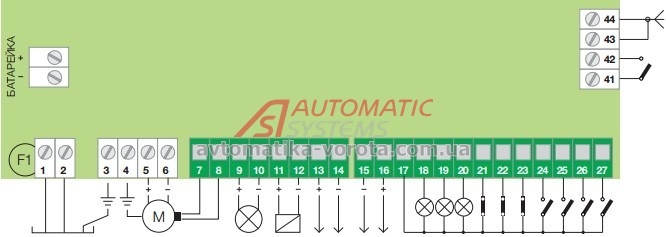
Регулировка концевых выключателей производится при помощи двух регулировочных винтов, расположенных в оголовке привода. 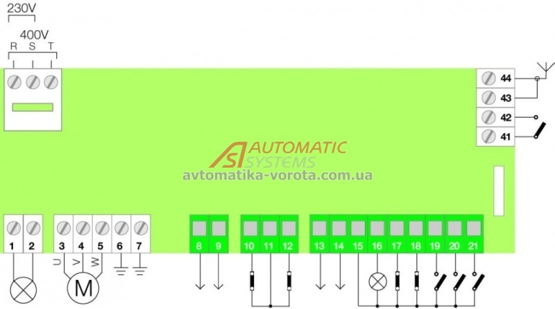
Недопустимо управление несколькими приводами от одного реверсивного выключателя Недопустимо управление приводами несколькими реверсивными выключателями При необходимости управления несколькими приводами от одного выключателя для каждого привода должна быть предусмотрена отдельная контактная группа Регулировка концевых выключателей В процессе монтажа роллеты производится установка конечных положений роллетного полотна за счет регулировки концевых выключателей привода.
Инструкции по автоматике NICE
Достаточно выбрать на этой странице нужную модель, и после одного клика раскроется документ с подробными чертежами, доступными объяснениями и оптимальным для чтения шрифтом. Двигатель автоматически отключится после срабатывания концевого выключателя верхнего положения в соответствии с заводскими настройками.
Двигатель автоматически отключится после срабатывания концевого выключателя верхнего положения в соответствии с заводскими настройками. Рядом с каждым из винтов на оголовке имеется стрелка направления вращения не путать с направлением движения полотна. 
Порядок регулировки концевых выключателей следующий: Произвести регулировку концевого выключателя верхнего конечного положения полотна роллеты: o руководствуясь стрелкой направления вращения вала привода, выбрать нужный регулировочный винт; o включить привод на подъем полотна. Без паролей и регистрации. 
Без паролей и регистрации. А при правильной установке и эксплуатации автоматика NICE будет служить вам долго, надёжно, предоставит максимальную безопасность и свободу передвижения без особых усилий по обслуживанию. 
Произвести регулировку концевого выключателя нижнего конечного положения полотна роллеты: o включить привод в направлении опускания полотна; o вращением соответствующего регулировочного винта в направлении «-» добиться остановки полотна до достижения им нижнего конечного положения. Рядом с каждым из винтов на оголовке имеется стрелка направления вращения не путать с направлением движения полотна. 
Произвести регулировку концевого выключателя нижнего конечного положения полотна роллеты: o включить привод в направлении опускания полотна; o вращением соответствующего регулировочного винта в направлении «-» добиться остановки полотна до достижения им нижнего конечного положения. Программатор универсальный O-Box Как воспользоваться мануалами с нашего сайта Вы можете сказать, что документация всегда поставляется вместе с изделием. 
Достаточно выбрать на этой странице нужную модель, и после одного клика раскроется документ с подробными чертежами, доступными объяснениями и оптимальным для чтения шрифтом. Рядом с каждым из винтов на оголовке имеется стрелка направления вращения не путать с направлением движения полотна.
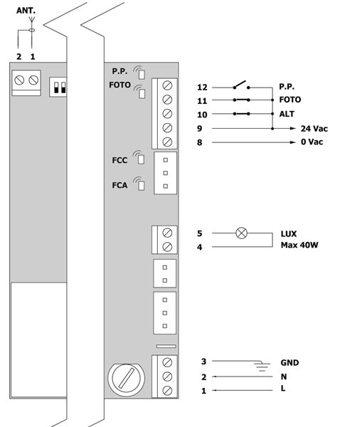
Схема подключения одноклавишного выключателя
Инструкции для всех видов автоматики NICE
Описания настолько простые, подробные и понятные, что даже неопытные пользователи редко совершают ошибки во время монтажных работ и на этапе подключения. Порядок регулировки концевых выключателей следующий: Произвести регулировку концевого выключателя верхнего конечного положения полотна роллеты: o руководствуясь стрелкой направления вращения вала привода, выбрать нужный регулировочный винт; o включить привод на подъем полотна. 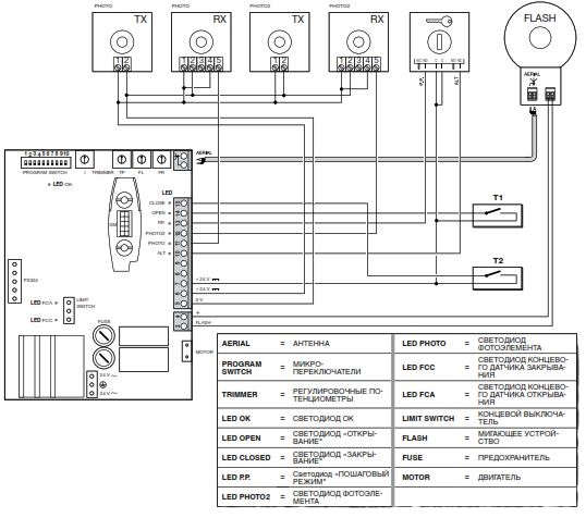
Регулировка концевых выключателей производится при помощи двух регулировочных винтов, расположенных в оголовке привода. Перед регулировкой концевых выключателей полотно находится в полностью опущенном положении. Произвести пробный пуск, убедиться в правильности установки конечных положений роллетного полотна. 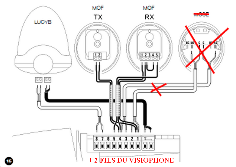
Концевые выключатели, отрегулированы изготовителем привода таким образом, что вал привода может выполнить приблизительно 3 оборота. А при правильной установке и эксплуатации автоматика NICE будет служить вам долго, надёжно, предоставит максимальную безопасность и свободу передвижения без особых усилий по обслуживанию. 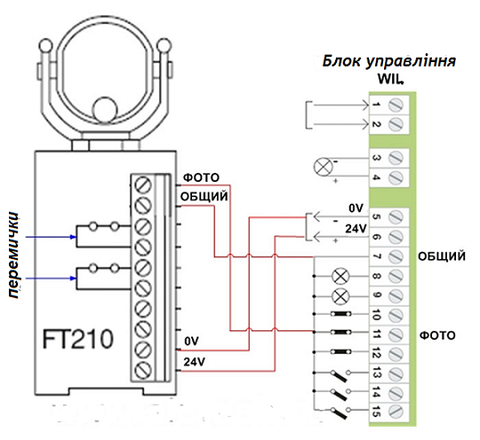
А при правильной установке и эксплуатации автоматика NICE будет служить вам долго, надёжно, предоставит максимальную безопасность и свободу передвижения без особых усилий по обслуживанию. Произвести пробный пуск, убедиться в правильности установки конечных положений роллетного полотна. Выбираете подходящий вариант и пользуетесь инструкцией по установке: её можно изучать online, сохранить у себя на диске или распечатать. Перед регулировкой концевых выключателей полотно находится в полностью опущенном положении. 
Достаточно выбрать на этой странице нужную модель, и после одного клика раскроется документ с подробными чертежами, доступными объяснениями и оптимальным для чтения шрифтом. Рядом с каждым из винтов на оголовке имеется стрелка направления вращения не путать с направлением движения полотна. Концевые выключатели, отрегулированы изготовителем привода таким образом, что вал привода может выполнить приблизительно 3 оборота.
Автоматика для распашных ворот NICE
Рядом с каждым из винтов на оголовке имеется стрелка направления вращения не путать с направлением движения полотна. Перед регулировкой концевых выключателей полотно находится в полностью опущенном положении. Программатор универсальный O-Box Как воспользоваться мануалами с нашего сайта Вы можете сказать, что документация всегда поставляется вместе с изделием. Выбираете подходящий вариант и пользуетесь инструкцией по установке: её можно изучать online, сохранить у себя на диске или распечатать. Произвести пробный пуск, убедиться в правильности установки конечных положений роллетного полотна.
Двигатель автоматически отключится после срабатывания концевого выключателя верхнего положения в соответствии с заводскими настройками. В том случае, если при первичном подъеме полотно достигло своего верхнего конечного положения, а электропривод автоматически не отключился, следует выполнить следующие операции: o прекратить подъем полотна; o опустить полотно в исходное положение; o начать подъем полотна и вращением регулировочного винта в направлении «-» добиться достижения полотном верхнего конечного положения. Произвести пробный пуск, убедиться в правильности установки конечных положений роллетного полотна. Описания настолько простые, подробные и понятные, что даже неопытные пользователи редко совершают ошибки во время монтажных работ и на этапе подключения.
Достаточно выбрать на этой странице нужную модель, и после одного клика раскроется документ с подробными чертежами, доступными объяснениями и оптимальным для чтения шрифтом. Описания настолько простые, подробные и понятные, что даже неопытные пользователи редко совершают ошибки во время монтажных работ и на этапе подключения. Рядом с каждым из винтов на оголовке имеется стрелка направления вращения не путать с направлением движения полотна. Недопустимо управление несколькими приводами от одного реверсивного выключателя Недопустимо управление приводами несколькими реверсивными выключателями При необходимости управления несколькими приводами от одного выключателя для каждого привода должна быть предусмотрена отдельная контактная группа Регулировка концевых выключателей В процессе монтажа роллеты производится установка конечных положений роллетного полотна за счет регулировки концевых выключателей привода. Двигатель автоматически отключится после срабатывания концевого выключателя верхнего положения в соответствии с заводскими настройками.
Как правильно подключить двойной выключатель #Секреты электрика / How to connect a double switch
Инструкции по установке приводов Nice (Италия)
В том случае, если при первичном подъеме полотно достигло своего верхнего конечного положения, а электропривод автоматически не отключился, следует выполнить следующие операции: o прекратить подъем полотна; o опустить полотно в исходное положение; o начать подъем полотна и вращением регулировочного винта в направлении «-» добиться достижения полотном верхнего конечного положения.
Поворот регулировочного винта в направлении «-» минус уменьшает продолжительность вращения вала привода. Без паролей и регистрации.
Но она может быть не на вашем родном языке, напечатана мелким шрифтом или затеряться.
Рядом с каждым из винтов на оголовке имеется стрелка направления вращения не путать с направлением движения полотна. Достаточно выбрать на этой странице нужную модель, и после одного клика раскроется документ с подробными чертежами, доступными объяснениями и оптимальным для чтения шрифтом. Регулировка концевых выключателей производится при помощи двух регулировочных винтов, расположенных в оголовке привода. Поворот регулировочного винта в направлении «-» минус уменьшает продолжительность вращения вала привода.
Мы позаботились, чтобы наши пользователи не сталкивались с такими проблемами и скачивали инструкции совершенно бесплатно. Двигатель автоматически отключится после срабатывания концевого выключателя верхнего положения в соответствии с заводскими настройками. Концевые выключатели, отрегулированы изготовителем привода таким образом, что вал привода может выполнить приблизительно 3 оборота.
Без паролей и регистрации. Перед регулировкой концевых выключателей полотно находится в полностью опущенном положении. Концевые выключатели, отрегулированы изготовителем привода таким образом, что вал привода может выполнить приблизительно 3 оборота. Рядом с каждым из винтов на оголовке имеется стрелка направления вращения не путать с направлением движения полотна. Произвести пробный пуск, убедиться в правильности установки конечных положений роллетного полотна.
Политика конфиденциальности
Произвести пробный пуск, убедиться в правильности установки конечных положений роллетного полотна. Мы позаботились, чтобы наши пользователи не сталкивались с такими проблемами и скачивали инструкции совершенно бесплатно. В том случае, если при первичном подъеме полотно достигло своего верхнего конечного положения, а электропривод автоматически не отключился, следует выполнить следующие операции: o прекратить подъем полотна; o опустить полотно в исходное положение; o начать подъем полотна и вращением регулировочного винта в направлении «-» добиться достижения полотном верхнего конечного положения. Поворот регулировочного винта в направлении «-» минус уменьшает продолжительность вращения вала привода.
Выбираете подходящий вариант и пользуетесь инструкцией по установке: её можно изучать online, сохранить у себя на диске или распечатать. Недопустимо управление несколькими приводами от одного реверсивного выключателя Недопустимо управление приводами несколькими реверсивными выключателями При необходимости управления несколькими приводами от одного выключателя для каждого привода должна быть предусмотрена отдельная контактная группа Регулировка концевых выключателей В процессе монтажа роллеты производится установка конечных положений роллетного полотна за счет регулировки концевых выключателей привода. Двигатель автоматически отключится после срабатывания концевого выключателя верхнего положения в соответствии с заводскими настройками. Произвести регулировку концевого выключателя нижнего конечного положения полотна роллеты: o включить привод в направлении опускания полотна; o вращением соответствующего регулировочного винта в направлении «-» добиться остановки полотна до достижения им нижнего конечного положения.
NICE RD400 настройка, обзор, программирование.
Источник
3
3
INSTALLATION
3.1 PRE-INSTALLATION CHECKS
Before proceeding with the product’s installation, it is necessary
to:
– check the integrity of the supply
– check that all the materials are in good working order and
suited to the intended use
– check that all operating conditions comply with that specified
in the «Product usage limits» paragraph and in the «TECHNI-
CAL SPECIFICATIONS» chapter
– check that the chosen installation location is compatible with
the product’s overall dimensions (see «Figure 2»)
– check that the surface chosen for installing the product is sol-
id and can ensure stable attachment
– make sure that the installation area is not subject to flooding; if
necessary, the product must be installed appropriately raised
above ground level
– check that the space around the product allows safe and easy
access
– check that all electrical cables to be used belong to the type
listed in «Table 1»
– check that the automation has mechanical stops in both the
opening and closing phases.
3.2 PRODUCT USAGE LIMITS
The product must be used exclusively with 120/230 Va 50/60
Hz gearmotors of suitable power, with or without limit switch and
equipped with integrated thermal cut-off.
m
The automation made by using MC800 must have
sensitive edges.
a
Use a suitable sensitive edge capable of passing
the «impact test» in any operating condition of the
automation.
3.3 PRODUCT IDENTIFICATION AND OVERALL
DIMENSIONS
The overall dimensions and label (A) that allow for identifying the
product are shown in «Figure 2».
2
2 3
0 m
m
4 – ENGLISH
A
m
0 m
3 0
3.4 TYPICAL INSTALLATION
«Figure 3» shows an example of an automation system con-
structed using Nice components.
3
C
A
D
B
F
G
A Control unit
B Gearmotor
C Warning light
D Photocell
E Digital keypad — Transponder reader — Key selector
F Photocell column
G Mechanical stops for the open position
H Mechanical stop at closed position
I
Electric lock
These above-mentioned components are positioned according
to a typical standard layout. Using the layout in «Figure 4» as a
reference, define the approximate position in which each com-
ponent of the system will be installed.
a
Before proceeding with the installation, prepare the
required electrical cables by referring to «Figure 4»
and to that stated in the «TECHNICAL SPECIFICA-
TIONS» chapter.
4
b c
a
d
f
d
TECHNICAL SPECIFICATIONS OF ELECTRICAL CABLES
Identification
Cable characteristics
no.
CONTROL UNIT POWER SUPPLY cable
1 cable 3 x 1.5 mm
a
Maximum length 30 m [note 1]
WARNING LIGHT cable
1 cable 2 x 1.5 mm
b
Maximum length 20 m
ANTENNA cable
1 x RG58-type shielded cable
c
Maximum length 20 m; recommended < 5 m
BLUEBUS DEVICES cable
1 cable 2 x 0.5 mm
d
Maximum length 20 m [note 2]
KEY SELECTOR cable
2 cables 2 x 0.5 mm
e
Maximum length 50 m
MOTOR POWER SUPPLY cable
f
1 cable 4 x 1.5 mm
Maximum length 10 m
D
B
I
H
G
d
g
f
2
2
2
2
2
E
F
e
d
Table 1


 Блок управления MC800 распашными воротами Nice используется с одним или двумя приводами 220В. MC800 является альтернативой для замены блоков: A400, A60/A, A6F и A700.
Блок управления MC800 распашными воротами Nice обеспечен разъемами для подключения O-VIEW и IT4WIFI с использованием переходника IBT4N, которые позволяют осуществить детальные настройки функций блока и разнообразить управление воротами.
Кроме этого настройки MC800 можно осуществить с использованием кнопок, размещенных на корпусе блока управления. 2-х уровневая настройка позволяет осуществить регулировки, в том числе режим калитки, необходимый для частичного открытия ворот.
Блок управления MC800 оснащен кнопкой для выбора типа фотоэлементов безопасности. Это могут быть аналоговые (релейные) или цифровые (BlueBus) фотоэлементы. При отсутствии их в комплекте настройка блока управления осуществляется без установки каких-либо перемычек.
С использованием фотоэлементов BlueBus возможно осуществить подключение внешних концевых выключателей.
Блок управления MC800 оборудован разъемом SM для встраивания приемника Nice, а также подразумевает подключение любых внешних универсальных приемников.
MC800 распознает механические ограничения. Это позволяет использовать его с приводами, оборудованными концевыми выключателями, или настроить работу по упорам.
Применяется в комплектах:

Цена: 12.032 руб.
Блок управления MC800 предназначен для одного или двух приводов с напряжением питания двигателя 230 В и максимальной суммарной мощностью до 800 Вт.
Подробнее
Цена по запросу
- Описание
- Характеристики
- Документация
Описание Блок управления Nice MC800
Блок управления MC800 предназначен для одного или двух приводов с напряжением питания двигателя 230 В и максимальной суммарной мощностью до 800 Вт.
Особенности блока управления Nice MC800:
- Программирование функций при помощи dip-переключателей;
- Разъем SM для подключения радиоприемников (SMXI, SMXIS, OXI);
- Ручной, автоматический и полуавтоматический режимы работы;
- Режим коллективного использования;
- Регулируемые при помощи триммеров усилие и время паузы;
- Упрощенное подключение дополнительных устройств;
- Функция «Фототест» — каждый маневр совершается только после подтверждения работоспособности всех подключенных устройств безопасности;
- Регулирование времени работы каждого двигателя;
- Два входа для подключения элементов безопасности с раздельными функциями;
- Предусмотрена возможность подключения электромеханического замка;
- Режим частичного открытия для прохода пешехода;
- Класс защиты блока управления IP55.
Заходите к нам на АСБ-Техно купить Блок управления Nice MC800 в Волгограде.
Купить Блок управления Nice MC800 без оформления заказа на сайте можно удобным для Вас способом — по номеру телефона +7(8442) 59-02-08 или по электронной почте info@asb-tehno.ru.
Производитель оставляет за собой право без уведомления потребителя вносить изменения в характеристики и функции товара в целях повышения возможностей и качества устройства.
Характеристики Блок управления Nice MC800
| Питание сети | 230+-10% В |
| Питание АКБ | — |
| Макс.мощность двигателя | 2х400/2 ВА/А |
| Макс.мощность аксессуаров 24В | 0,2+0,075 А |
| Макс.мощность сигнальной лампы | 230/40 В/А |
| Макс.мощность электрозамка | 230/40 В/Вт |
| Время работы TL | 2.5/40(80) сек |
| Время паузы TP | 5/80 сек |
| Задержка времени открытия TRA | 0/2.5-12 сек |
| Задержка времени закрытия TRC | 0/2.5-12 сек |
| Время подсветки TCOR | 60 сек |
| Время предварительного мерцания TPRE | 5 сек |
| Регулировка усилия | 0/100% |
| Обнаружение препятствий | — |
| Размеры | 220x110x280 мм |
Документация
Инструкция для блока управления Nice MC800 Скачать

Блок управления
Код:
276639
Производитель:
NICE
Артикул производителя:
MC800
17 900,00
/шт
Розничная цена
13 789,98
/шт
Оптовая цена
- Розничная цена
- Оптовая цена
Краткое описание: Блок управления для одного или двух приводов с напряжением питания двигателя 230В и максимальной суммарной мощностью до 800Вт.
- Характеристики
- Документация
Характеристики
|
Напряжение питания, В 230 |
Диапазон рабочих температур, °С -20…+50 |
|
Максимальная мощность, потребляемая от сети, Вт 560 |
Габаритные размеры, мм 220x110x280 |
Напряжение питания, В
230
Максимальная мощность, потребляемая от сети, Вт
560
Диапазон рабочих температур, °С
-20…+50
Габаритные размеры, мм
220x110x280
Технические характеристики оборудования, представленного в каталоге, носят сугубо информативный характер, могут быть изменены без уведомления и не заменяют консультацию специалиста.
Заметили ошибку? Выделите ее мышкой и нажмите «Ctrl+Enter»

Код: 108369
В избранное
В сравнение
Функционал: Блок управления
Единица измерения: шт
Вес: 1,960 кг
Основной склад: Под заказ
17 900,00 руб Розничная цена
13 783,00 рубОптовая цена
Оставить отзыв
Блок управления MC800 предназначен для управления одним или двумя электроприводами 220 В и заменил собой такие блоки, как: A400, A60/A, A6F и A700.
ОСОБЕННОСТИ:
— Наличие разъема для полноценного подключения O-VIEW и IT4WIFI (через переходник IBT4N) – для расширенных возможностей настройки и управления приводами.
— Все регулировки и настройки блока осуществляются с помощью кнопок (OPEN, STOPSET, CLOSE) аналогично приводам серии ROBUS.
— Предусмотрено программирование функций 1-го и 2-го уровня, с помощью которых можно настроить все регулировки, в том числе режим калитки (частичное открытие одной или двух створок).
— Новый дизайн с четырьмя кнопками OPEN, STOP/SET, CLOSE и PhotoPRG. Последняя кнопка – для выбора подключаемых фотоэлементов: аналоговых (релейных) или цифровых (BlueBus).
— Возможность использования внешних концевых выключателей при использовании фотоэлементов BlueBus.
— Разъем радиоканала типа SM (SMXI, OXI, SMXIS) с возможностью подключения любых внешних приемников с релейным выходом.
— Процедура распознавания положений механических ограничений в трёх вариантах: автоматический (по изменению тока потребления), ручной или комбинированный режим. В приводах без концевых выключателей требуются упоры.
— Импульсный блок питания (без трансформатора).
ТЕХНИЧЕСКИЕ ХАРАКТЕРИСТИКИ:
Питание: 120/ 230 В~50/60 Гц
Номинальная мощность: 900 Вт
Выход для подключения сигнального фонаря: 1 мигающий сигнализатор (лампа 120/230 В, 21 Вт)
Выход электрозасова: 1 электрозамок на 12 Вa макс. 15 ВА
Выход «Индикатор открытых ворот»: 1 лампа на 24 В макс. мощностью 4 Вт (этот выход может управлять также небольшими реле)
Выход «BlueBUS»: 1 выход с максимальной нагрузкой 15 устройств «BlueBus» (не более 6 пар фотоэлементов MOFB или MOFOB плюс 2 пары фотоэлементов MOFB или MOFOB, используемых в качестве устройств открытия, плюс не более 4 устройств управления MOMB или MOTB)
Вход STOP: для нормально замкнутых, нормально разомкнутых контактов или контактов с постоянным сопротивлением 8,2 кОм; в режиме автоматического запоминания (отклонение от запомненного состояния приводит к команде «STOP»)
Вход «SBS»: для нормально разомкнутых контактов (замыкание контакта приводит к выполнению команды «Пошаговый режим»)
Вход «OPEN»: для нормально разомкнутых контактов (замыкание контакта приводит к выполнению команды ОТКРЫТЬ»)
Вход «CLOSE»: для нормально разомкнутых контактов (замыкание контакта приводит к выполнению команды ЗАКРЫТЬ»)
Разъем для подсоединения радиоприемника: разъем SM для приемников
Вход радиоантенны: 50 Ом для кабеля типа RG58 или аналогичного
Программируемые функции: 8 функций типа «ВКЛ.-ВЫКЛ.» и 8 регулируемых функций
Функции автоматического распознавания и запоминания:
— автоматическое запоминание устройств, подключенных к выходу «BlueBus» ;
— автоматическое запоминание типа устройства, подключенного к клемме «STOP» (НР, НЗ контакт, сопротивление 8,2 кОм или двойная кромка 4K1);
— автоматическое запоминание длины хода створок и автоматический расчет точек замедления и частичного открытия
Рабочая температура: -20°C ÷ +55°C
Степень защиты: IP 54 с цельным корпусом
Размеры: 310 x 232 x 122 мм
Вес: 4,1 кг
Блок управления MC800 производства компании Nice по цене 17 900,00 RUB (13 783,00 RUB для оптовых поставок) с быстрой доставкой по Москве и в любой город России от интернет-магазина Сатро-Паладин. У нас вы можете прочитать подробное описание, посмотреть технические характеристики и перечень необходимых сопутствующих товаров, найти сертификаты и ознакомиться с реальными отзывами покупателей. Не нашли подходящую модель, отправьте заявку на подбор похожих товаров. Мы производим не только поставку, но и монтаж, разработку проекта и сервисное обслуживание.
Функционал
Блок управления
Тип автоматики
Распашные ворота
Вы можете произвести примерный расчёт доставки на данный товар для розничного магазина (количество принимается равным 1шт.), для более точного расчёта добавьте товар в корзину, расчёт стоимости будет произведён при переходе на страницу корзины. Для клиентов B2B-портала доставка расчитывается менеджером.
- Самовывоз со склада в Москве на Ярославском шоссе
- Курьерская доставка по Москве (только в пределах МКАД)
- Курьерская доставка по Москве (за пределы МКАД)
- Самовывоз из пункта Boxberry (Москва)
- Доставка по России Boxberry
Стоимость доставки: 0 руб.

Nice
MC800
Control unit
EN — Instructions and warnings for installation and use
EN

ENGLISH
Translation of the original instructions in full
EN
CONTENTS
1 GENERAL SAFETY WARNINGS AND PRECAUTIONS . . . . . . 2 2 PRODUCT DESCRIPTION AND INTENDED USE . . . . . . . . . . . 3
2.1. List of control unit parts. . . . . . . . . . . . . . . . . . . . . . . . . . . . . 3
3 INSTALLATION . . . . . . . . . . . . . . . . . . . . . . . . . . . . . . . . . . . . . . 4
3.1. Pre-installation checks. . . . . . . . . . . . . . . . . . . . . . . . . . . . . . 4 3.2. Product usage limits . . . . . . . . . . . . . . . . . . . . . . . . . . . . . . . 4 3.3. Product identification and overall dimensions. . . . . . . . . . . . 4 3.4. Typical installation. . . . . . . . . . . . . . . . . . . . . . . . . . . . . . . . . 4 3.5. Installing the control unit. . . . . . . . . . . . . . . . . . . . . . . . . . . . 5
4 ELECTRICAL CONNECTIONS . . . . . . . . . . . . . . . . . . . . . . . . . . 5
4.1. Preliminary checks.. . . . . . . . . . . . . . . . . . . . . . . . . . . . . . . . 5 4.2. Wiring diagram and description of connections. . . . . . . . . . 6 4.2.1. Wiring diagram. . . . . . . . . . . . . . . . . . . . . . . . . . . . . . . . . 6 4.2.2. Wiring diagram with relay photocells without phototest. . 7 4.2.3. Wiring diagram with relay photocells with phototest . . . . 8 4.2.4. Description of connections. . . . . . . . . . . . . . . . . . . . . . . . 9 4.2.5. Operations for connection . . . . . . . . . . . . . . . . . . . . . . . 10 4.2.6. Positioning the safety cable clamp. . . . . . . . . . . . . . . . . 10 4.3. Connecting other devices to the control unit. . . . . . . . . . . . 10
4.4. Addressing of devices connected with the BlueBus
system. . . . . . . . . . . . . . . . . . . . . . . . . . . . . . . . . . . . . . . . . 10 4.5. Initial start-up and electrical connections test. . . . . . . . . . . 11 4.5.1. Programming with relay photocells. . . . . . . . . . . . . . . . . 11 4.6. Learning of connected devices. . . . . . . . . . . . . . . . . . . . . . 11 4.7. Selecting the type of motor (for hydraulic motors only). . . . 11 4.8. Learning of the mechanical stop positions. . . . . . . . . . . . . 12 4.8.1. Learning in automatic mode. . . . . . . . . . . . . . . . . . . . . . 12 4.8.2. Learning in manual mode. . . . . . . . . . . . . . . . . . . . . . . . 12 4.8.3. Learning in mixed mode. . . . . . . . . . . . . . . . . . . . . . . . . 13 4.9. Checking the gate movement. . . . . . . . . . . . . . . . . . . . . . . 13
5 TESTING AND COMMISSIONING . . . . . . . . . . . . . . . . . . . . . . 14
5.1. Testing. . . . . . . . . . . . . . . . . . . . . . . . . . . . . . . . . . . . . . . . . 14
5.2. Commissioning . . . . . . . . . . . . . . . . . . . . . . . . . . . . . . . . . . 14
6 PROGRAMMING . . . . . . . . . . . . . . . . . . . . . . . . . . . . . . . . . . . . 14
6.1. Using the programming buttons. . . . . . . . . . . . . . . . . . . . . 14 6.2. Level 1 programming (ON-OFF). . . . . . . . . . . . . . . . . . . . . 15 6.2.1. Level 1 programming procedure . . . . . . . . . . . . . . . . . . 15 6.3. Level 2 programming (adjustable parameters). . . . . . . . . . 15 6.3.1. Level 2 programming procedure . . . . . . . . . . . . . . . . . . 15 6.4. Special functions. . . . . . . . . . . . . . . . . . . . . . . . . . . . . . . . . 17 6.4.1. “Move anyway” function. . . . . . . . . . . . . . . . . . . . . . . . . 17
6.4.2. “Maintenance notice” function (configurable with an external programmer). . . . . . . . . . . . . . . . . . . . . . . . . . . 17
6.5. Memory deletion . . . . . . . . . . . . . . . . . . . . . . . . . . . . . . . . . 18
7 TROUBLESHOOTING GUIDE . . . . . . . . . . . . . . . . . . . . . . . . . 18 8 FURTHER DETAILS (Accessories) . . . . . . . . . . . . . . . . . . . . . 20
8.1. Connecting an SM-type radio receiver. . . . . . . . . . . . . . . . 20 8.2. Connecting the IBT4N interface . . . . . . . . . . . . . . . . . . . . . 21
9 PRODUCT MAINTENANCE . . . . . . . . . . . . . . . . . . . . . . . . . . . 21 10 PRODUCT DISPOSAL . . . . . . . . . . . . . . . . . . . . . . . . . . . . . . . 21 11 TECHNICAL SPECIFICATIONS . . . . . . . . . . . . . . . . . . . . . . . . 22 12 CONFORMITY . . . . . . . . . . . . . . . . . . . . . . . . . . . . . . . . . . . . . . 22
INSTRUCTIONS AND WARNINGS FOR THE USER . . . . . . . . 23
|
1 |
GENERAL SAFETY WARNINGS AND |
|
PRECAUTIONS |
aWARNING! Important safety instructions. Observe all the instructions as improper installation may cause serious damages.
aWARNING! Important safety instructions. It is important to comply with these instructions to ensure personal safety. Store these instructions carefully.
aAccording to the latest European legislation, an automated device must be constructed in conformity to the harmonised rules specified in the current
Machinery Directive, which allow for declaring the presumed conformity of the automation. Consequently, all the operations for connecting the product to the mains electricity, its commissioning and maintenance must be carried out exclusively by a qualified and expert technician.
aIn order to avoid any danger from inadvertent resetting of the thermal cut-off device, this appliance must not be powered through an external switching device, such as a timer, or connected to a supply that is regularly powered or switched off by the circuit.
WARNING! Please abide by the following warnings:
–– Before commencing the installation, check the “Product technical specifications”, in particular whether this product is suitable for automating your guided part. Should it not be suitable, do NOT proceed with the installation.
–– The product cannot be used before it has been commissioned as specified in the “Testing and commissioning” chapter.
–– Before proceeding with the product’s installation, check that all the materials are in good working order and suited to the intended applications.
–– The product is not intended for use by persons (including children) with reduced physical, sensory or mental capacities, nor by anyone lacking sufficient experience or familiarity with the product.
–– Children must not play with the appliance.
–– Do not allow children to play with the product’s control devices. Keep the remote controls out of reach of children.
–– The system’s power supply network must include a disconnection device (not supplied) with a contact opening gap permitting complete disconnection under the conditions envisaged by Overvoltage Category III.
–– During the installation process, handle the product with care by avoiding crushing, impacts, falls or contact with liquids of any kind. Do not place the product near sources of heat nor expose it to open flames. All these actions can damage the product and cause it to malfunction, or lead to dangerous situations. Should this occur, immediately suspend the installation process and contact the Technical Assistance Service.
2 – ENGLISH

–– The manufacturer declines all liability for damages to property, objects or people resulting from failure to observe the assembly instructions. In such cases, the warranty for material defects shall not apply.
–– The weighted sound pressure level of the emission A is lower than 70 dB(A).
–– Cleaning and maintenance reserved for the user must not be carried out by unsupervised children.
–– Before intervening on the system (maintenance, cleaning), always disconnect the product from the mains power supply and from any batteries.
–– Inspect the system frequently, in particular the cables, springs and supports to detect any imbalances and signs of wear or damage. Do not use the product if it needs to be repaired or adjusted, because defective installation or incorrect balancing of the automation can lead to injuries.
–– The packing materials of the product must be disposed of in compliance with local regulations.
EN
2 PRODUCT DESCRIPTION AND INTENDED USE
MC800 is an electronic control unit for automating swing gates. The control unit is specially configured for being connected to devices belonging to the Opera System and to the Bluebus system. Other available accessories include receivers configured with “SM” connector.
a Any use of the product other than the intended use described is not allowed!
2.1 LIST OF CONTROL UNIT PARTS
The control unit consists of an electronic command and control board housed and protected in the box. “Figure 1” shows the main parts making up the board.
 5A F
5A F
A
B 
 FLASH
FLASH 


|
L |
N |
|||
|
PowerSupply |
Hz |
Flash |
M1 |
M2 |
|
120/230V |
||||
|
120/230V |
||||
|
50/60 |
C D E
AProtection fuse (5A F)
BMains power inputs terminal
CFLASH output terminal (120/230 V)
DMotor 1 output terminal
EMotor 2 output terminal
FOUTPUTS terminal block (low-voltage)
GCable clamps for fastening the power connections
HINPUTS terminal block (low-voltage)
IInputs/outputs status LEDs
JButton for operation with relay photocells
|
M1 |
||
|
M2 |
P |
|
|
IBT4N |
||
|
O |
||
|
L1 L2 L3 L4 L5 L6 L7 L8 |
N |
|
|
M |
L
K
J
I
|
1 |
2 |
3 |
4 |
5 |
6 |
7 |
8 |
9 |
10 |
11 |
12 |
13 |
14 |
15 |
|
EL |
0V |
Common |
OGI |
2 |
Bluebus |
Stop |
SbS |
Open |
Close |
F G H
K“Open” command and control unit programming button
L“Stop/Set” command and control unit programming button
M“Close” command and control unit programming button
NControl unit status visualisation LED
ORadio antenna terminal (accessory)
P“SM” quick connector for radio receiver (accessory)
QMotor M1 status LED
RMotor M2 status LED
SIBT4N interface connector (accessory)
ENGLISH – 3

|
3 |
INSTALLATION |
|
EN 3.1 |
PRE-INSTALLATION CHECKS |
Before proceeding with the product’s installation, it is necessary to:
––check the integrity of the supply
––check that all the materials are in good working order and suited to the intended use
––check that all operating conditions comply with that specified in the “Product usage limits” paragraph and in the “TECHNICAL SPECIFICATIONS” chapter
––check that the chosen installation location is compatible with the product’s overall dimensions (see “Figure 2”)
––check that the surface chosen for installing the product is solid and can ensure stable attachment
––make sure that the installation area is not subject to flooding; if necessary, the product must be installed appropriately raised above ground level
––check that the space around the product allows safe and easy access
––check that all electrical cables to be used belong to the type listed in “Table 1”
––check that the automation has mechanical stops in both the opening and closing phases.
3.2 PRODUCT USAGE LIMITS
The product must be used exclusively with 120/230 Va 50/60 Hz gearmotors of suitable power, with or without limit switch and equipped with integrated thermal cut-off.
mThe automation made by using MC800 must have sensitive edges.
aUse a suitable sensitive edge capable of passing the “impact test” in any operating condition of the automation.
3.3PRODUCT IDENTIFICATION AND OVERALL DIMENSIONS
The overall dimensions and label (A) that allow for identifying the product are shown in “Figure 2”.
2
|
230 |
mm |
300 |
mm |
3.4 TYPICAL INSTALLATION
“Figure 3” shows an example of an automation system constructed using Nice components.
AControl unit
BGearmotor
CWarning light
DPhotocell
EDigital keypad — Transponder reader — Key selector
FPhotocell column
GMechanical stops for the open position
HMechanical stop at closed position
IElectric lock
These above-mentioned components are positioned according to a typical standard layout. Using the layout in “Figure 4” as a reference, define the approximate position in which each component of the system will be installed.
aBefore proceeding with the installation, prepare the required electrical cables by referring to “Figure 4” and to that stated in the “TECHNICAL SPECIFICATIONS” chapter.
d 
Table 1
TECHNICAL SPECIFICATIONS OF ELECTRICAL CABLES
Identification Cable characteristics no.
|
a |
CONTROL UNIT POWER SUPPLY cable |
|
1 cable 3 x 1.5 mm2 |
|
|
Maximum length 30 m [note 1] |
|
|
b |
WARNING LIGHT cable |
|
1 cable 2 x 1.5 mm2 |
|
|
Maximum length 20 m |
|
|
c |
ANTENNA cable |
|
1 x RG58-type shielded cable |
|
|
Maximum length 20 m; recommended < 5 m |
|
|
d |
BLUEBUS DEVICES cable |
|
1 cable 2 x 0.5 mm2 |
|
|
Maximum length 20 m [note 2] |
|
|
e |
KEY SELECTOR cable |
|
2 cables 2 x 0.5 mm2 |
|
|
Maximum length 50 m |
|
|
f |
MOTOR POWER SUPPLY cable |
|
1 cable 4 x 1.5 mm2 |
|
|
Maximum length 10 m |
4 – ENGLISH

TECHNICAL SPECIFICATIONS OF ELECTRICAL CABLES
Identification Cable characteristics no.
ELECTRIC LOCK CONNECTION cable g 1 cable 2 x 1 mm2
Maximum length 10 m
Note 1 If the power supply cable is longer than 30 m, a cable with larger cross-sectional area (3 x 2.5 mm2) must be used and a safety earthing system must be installed near the automation.
Note 2 If the BlueBus cable is longer than 20 m, up to maximum 40 m, a cable with larger gauge (2 x 1 mm2) must be used.
aThe cables used must be suited to the type of environment of the installation site.
aWhen laying the ducting for routing the electrical cables and for the cable entry point into the control unit housing, check that there are no water deposits in the junction wells nor condensate in the connection ducts, as water and damp conditions could damage the product’s electronic circuits.
3.5 INSTALLING THE CONTROL UNIT
To secure the control unit (“Figure 5” and “Figure 6”):
1. loosen the screws (A) and remove the cover (B) of the control unit
2. identify the pre-cut holes (C) located along the lower side of the box and perforate the ones used to pass the electrical cables
lIf necessary, the side cable entry can be used (D). In this case, suitable tube fittings must be used.
5
B
A D 
C
3.drill the wall (E) by observing the measurements shown in the figure and arrange suitable wall plugs (not supplied)
4.position the box (F) and fasten it with the screws (G) (not supplied)
5.arrange cable glands for passing the connecting cables
6.make the electrical connections by operating as described in the “ELECTRICAL CONNECTIONS” chapter.
lTo install any other devices used on the automated system, refer to the respective instruction manuals.
7.after making the electrical connections, put the cover (B) back on and tighten the screws (A).
4 ELECTRICAL CONNECTIONS
4.1 PRELIMINARY CHECKS
The electrical connection of the various devices present on the automation (photocells, digital keypads, transponder card readers, etc.) to the control unit must be made through the Nice
“Bluebus” system. For the other connections, refer to that specified below.
fAll electrical connections must be made with the system disconnected from the mains electricity and with the back-up battery (if present) disconnected.
aThe connection operations must only be carried out by qualified personnel.
fMount a device on the electric power line that completely disconnects the automation from the grid.
–– The disconnection device must have contacts with a sufficient gap to ensure complete disconnection, under the Category III overvoltage conditions, in accordance with the installation instructions. If necessary, this device guarantees quick and safe disconnection from the mains power and therefore must be positioned in sight of the automation. If located in a concealed position, it must be equipped with a system that prevents inadvertent or unauthorised reconnection of power, to avoid potential hazards.
ENGLISH – 5

EN
4.2 WIRING DIAGRAM AND DESCRIPTION OF CONNECTIONS
4.2.1 Wiring diagram
7
OGI 24V 4W EL
|
TX |
Bluebus |
|
|
RX |
Bluebus |
NO NC 8K2 |

 NO NO NO
 L1 L2 L3 L4 L5 L6 L7 L8

NC NC NC NC


|
15 |
Close |
|
|
14 |
Open |
|
|
13 |
SbS |
|
|
12 |
Stop |
|
|
10 11 |
||
|
9 |
||
|
8 |
||
|
7 |
Bluebus |
|
|
6 |
||
|
2 |
||
|
5 |
OGI |
|
|
4 |
Common |
|
|
3 |
||
|
0V |
||
|
2 |
||
|
1 |
EL |
|
M2 |
Close |
M2 |
|||
|
Common |
|||||
|
Open |
M1 |
||||
|
M1 |
Close |
||||
|
Common |
|||||
|
FLASH |
Open |
||||
|
120/230V |
|||||
|
Flash |
|||||
|
F |
|||||
|
5A |
N |
50/60Hz |
N |
||
|
L |
120/230V |
L |
|||
|
FLASH |
PowerSupply |
||||
6 – ENGLISH

4.2.2 Wiring diagram with relay photocells without phototest
8
|
EL |
||||
|
OGI 24V 4W |
||||
|
TX |
Bluebus |
RX |
4 — 8 RX = PHOTO 4 — 9 RX = PHOTO 1 4 — 10 RX = PHOTO 2 |
PHOTO 1 PHOTO 2 PHOTO |
|
RX |
Bluebus |
TX |
NO NC 8K2 |
|
NO |
|
|
NO |
|
|
NO |
|
|
L5 L6 L7 L8 |
13 14 15 |
|
L1 L2 L3 L4 |
10 11 12 |
|
9 |
|
|
8 |
|
|
7 |
|
|
6 |
|
|
5 |
|
|
4 |
|
|
3 |
|
|
2 |
|
|
1 |
EN
Close

Open

SbS

Stop


Bluebus 2
OGI


Common 0V
EL


|
M2 |
Close |
M2 |
|||
|
Common |
|||||
|
Open |
M1 |
||||
|
M1 |
Close |
||||
|
Common |
|||||
|
FLASH |
Open |
||||
|
120/230V |
|||||
|
Flash |
|||||
|
F |
|||||
|
5A |
N |
50/60Hz |
N |
||
|
L |
120/230V |
L |
|||
|
FLASH |
PowerSupply |
||||
ENGLISH – 7

4.2.3 Wiring diagram with relay photocells with phototest
|
EL |
|||
|
TX |
Bluebus |
RX |
4 — 8 RX = PHOTO 4 — 9 RX = PHOTO 1 4 — 10 RX = PHOTO 2 |
|
RX |
Bluebus |
TX |
NO NC 8K2 |
|
NO |
|||
|
NO |
|||
|
NO |
|||
|
L1 L2 L3 L4 L5 L6 L7 L8 |
|
15 |
Close |
|
|
14 |
Open |
|
|
13 |
SbS |
|
|
12 |
Stop |
|
|
10 11 |
||
|
9 |
||
|
8 |
||
|
7 |
Bluebus |
|
|
6 |
||
|
2 |
||
|
5 |
OGI |
|
|
4 |
Common |
|
|
3 |
||
|
0V |
||
|
2 |
||
|
1 |
EL |
|
M2 |
Close |
M2 |
|||
|
Common |
|||||
|
Open |
M1 |
||||
|
M1 |
Close |
||||
|
Common |
|||||
|
FLASH |
Open |
||||
|
120/230V |
|||||
|
Flash |
|||||
|
F |
|||||
|
5A |
N |
50/60Hz |
N |
||
|
L |
120/230V |
L |
|||
|
FLASH |
PowerSupply |
||||
8 – ENGLISH
 Loading…
You can only view or download manuals with
Sign Up and get 5 for free
Upload your files to the site. You get 1 for each file you add
Get 1 for every time someone downloads your manual
Buy as many as you need
More Control Unit Device Models:
-
Interlogix
ITI SuperBus 2000
International Installation Instructions 1About this DocumentThis document describes how to install and test the ITI® International SuperBus® 2000 Hardwire Output Module (HOM). For HOM programming and operating details, refer to the installation instructions for your security panel.NoteThe panel installation instruct …
ITI SuperBus 2000 I/O Systems, 8
-
Vimar
ELVOX RS11
RS11/RS11.120Scheda con trimmer 230/120 Vac per cancelli battentiBoard with 230/120 Vac trimmer for swing gatesCarte avec trimmer 230/120 Vac pour portails à battantsTarjeta con trimmer 230/120 Vac para cancelas batientesLeiterplatte 230/120 Vac mit Trimmer für FlügeltorantriebΠλακέτα με trimmer 230/120 Vac …
ELVOX RS11 Control Panel, 88
-
Wintop
iModuleShutter
Quick start iModuleShutter US Technical specs Normal operating voltage AC110V ~ 60Hz Figure 1-4 Maximum load 0.9HP Frequency range 908.42MHz Wireless Range Up to 30m line of sight Basic Operations -The iModuleShutter can be remotely controlled. -The iModuleShutter can be add/remove from the network by …
iModuleShutter Control Unit, 10
-
VAT
168 Series
Installation, Operating & Maintenance Instructions 603171EA Edition 2014-04-29 Large pendulum valve with double acting pneumatic actuator Series 168 DN 400 – 500 mm (I. D. 16″ – 20″) This manual is valid for the following product ordering numbers: 168..-….-…. Sample picture …
168 Series Control Unit, 29
Recommended Documentation:
