Комплексное решение для лаборатории
Подробное описание
- цифровой мультиметр
- функциональный генератор
- универсальный частотомер
- источник питания
в одном корпусе
- Габариты 370 × 375 × 165 мм
- Вес 15 кг
Технические характеристики MS-9150
Цифровой мультиметр
- Индикатор 3¾ разряда (max.
3999) с подсветкой
- Основной и один вспомогательный дисплей + линейная шкала
- Режим сохранения данных
- Сохранение максимального и минимального значения
- Память на 5 значений
- Подключение к компьютеру через порт RS-232C
|
Функция |
Диапазон |
Точность |
|
Постоянное напряжение |
400 мB / 4 / 40 / 400 B |
±0.3% + 1 ед. |
|
1000 B |
±0.5% + 1 ед. |
|
|
Переменное напряжение |
400 мB / 4 / 40 / 400 B |
±0.8% + 3 ед. |
|
750 B |
±1.0% + 3 ед. |
|
|
Постоянный ток |
40 / 400 мА |
±0.8% + 3 ед. |
|
20 А |
±1.0% + 3 ед. |
|
|
Переменный ток |
40 / 400 мА |
±1.5% + 3 ед. |
|
20 А |
±2.0% + 5 ед. |
|
|
Сопротивление |
400 Ом / 4 / 40 / 400 кОм / 4 МОм |
±0.5% + 1 ед. |
|
40 МОм |
±1.0% + 2 ед. |
|
|
Емкость |
4 / 40 / 400 нФ |
±2.0% + 3 ед. |
|
4 / 40 / 200 мкФ |
±3.0% + 5 ед. |
|
|
Логический пробник |
есть |
|
|
Тест диодов |
есть |
|
|
Прозвонка цепей |
есть |
Функциональный генератор
- Выходной сигнал: синус, прямоугольный, треугольный, импульсный, прямоуг. TTL уровня
- Частота: 0.02 Гц … 2 Мгц , 7 диапазонов
- Выходное напряжение ампл.: 1 … 10 В на нагрузке 50 Ом
- Выходной импеданс = 50 Ом или 600 Ом по выбору
- Аттенюатор -20 дБ
- Внутреннее и внешнее свипирование сигнала, период 20 мc … 2 c
Универсальный частотомер
- Пределы измерений: каналы А и В – 5 Гц … 100 МГц , канал С – 100 МГц … 1.3 ГГц
- Входное напряж.: каналы А и В – 5 Гц … 100 МГц, аттенюатор: ×1, ×20, канал С – 150 мВ
- Входное напряжение мах 3 В
- Период измерения 0.1 с 4 10 с
Источник питания
- Выход 1: 0 … 30 В, 0 … 2 А, стабилизация напряжения и тока
- Выход 2: 5 В фиксировано, 2 А
- Выход 3: 15 В фиксировано, 1 А
- Дисплей 3½ разряда с подсветкой
Варианты написания:
MS9150, MS 9150, MS9150, MS 9150, MS 9150, MS9150, MS-9150 MS 9150 MS9150, MS-9150 MS 9150 MS9150
![]()
f)OFFSET adjustment
—The DC voltage level of the output signal can be adjusted with the OFFSET control knob in the range of +/- 10 V.
—To set the DC voltage level, pull this control knob out. Turning to the right means positive voltage, turning to the left means negative voltage.
—If the control knob is pressed, the output voltage will have no DC voltage component.
g)Symmetry adjustment
—The symmetry of the output voltage can be changed in the range of 1:3 and 3:1.
The control knob carries the designation SYM.
—To change the symmetry of the waveforms, pull the SYM control knob and turn it slowly to the left (ccw) or to the right (cw). Refer to the table for the resulting waveforms.
|
BASIC WAVEFORMS |
CLOCK WISE (CW) |
COUNTER CLOCKWISE (CCW) |
|
SINE |
SKEWED SINE |
SKEWED SINE |
|
TRIANGLE |
SAWTOOTH |
SAWTOOTH |
Note!
Note that because of this adjustment of symmetry, the frequency can change and therefore should be readjusted.
h)SWEEP adjustment (Wobbler)
—To operate the built-in frequency sweep, pull the SWEEP WIDTH control knob and use it to adjust the width of the sweep signals in the range 100 : 1.
—To achieve maximum width, turn the frequency adjustment knob (with scale) to its left stop and the width control to its right stop.
—To adjust the speed of the sweep signal, turn the SWEEP RATE control knob slowly to the left or right. A linear sweep signal is obtained.
—A logarithmic sweep signal is possible by pulling the SWEEP RATE control knob.
i)TTL output
—The TTL level is available at the TTL OUT socket (BNC).
A TTL level is an «asymmetric square wave». It is asymmetrical because, in contrast to the sine or «pure» square waves, the signal does not cross zero, i.e. it has no negative voltage values (negative logic excepted).
—The TTL output can drive 20 «unit loads» when HIGH and 15 «unit loads» when LOW.
—One «unit load» is 40 µA for the HIGH and 1.6 mA for the LOW state.
j)Output impedance
—The output impedance of the generator output F/G OUT, is 50 Ohm or 600 Ohm depending on the setting of the 50 / 600 Ohm switch.
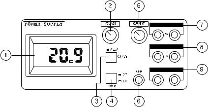
5.3 The DC voltage measuring instrument
|
Operating elements |
|||||||||||||||||||
|
1. |
Illuminated 3 1/2-position |
5. |
Adjustable current limiting |
||||||||||||||||
|
17 mm high LCD display |
6. |
Ground connector |
|||||||||||||||||
|
2. |
Voltage adjustment |
7. |
Fixed voltage output 5 V / 2 A |
||||||||||||||||
|
3. |
V/A display switch |
8. |
Fixed voltage output 15 V / 1 A |
||||||||||||||||
|
4. |
AC power main switch |
9. |
Adjustable output 0-30 V / 0-3 A |
Attention! Safety measures!
Protect the instrument from being dropped and from external mechanical damage by falling objects.
Do not short circuit the «+» and «-» terminals.
Never go beneath the maximum permitted load of 2.5 Ohm at the 5V/2A output and 15 Ohm at the 15V/1A output.
Basic settings
a)Before connecting the AC power cable, ensure that no load is present on the output terminals of the power supply.
b)Centralise the (CURRENT) current-limiting control knob.
c)Switch the AC power switch (POWER) on.
d)The LEDs under the legends 5 V and 15 V light up.
e)Connect the loads to the 5V and 15V output.
f)Switch the display switch to «V» (voltage) and set the desired output voltage.
g)Now connect the load to the output terminals «+» and «-» of the adjustable output. While doing this, observe the polarity of the load.
Attention!
All outputs are floating. Other outputs can either be grounded through the ground socket (= chassis) on the front panel (bottom right) or remain floating.
Current limiting characteristics
All 3 outputs are independently protected against overload and short circuit by means of a separate current limiting circuit.
a)Output 0 to 30 V, 3 A: protected by means of current limiting. If the output current increases due to a load of more than 3 A, the output voltage is reduced (with a short circuit to approx. 0.2 V).
b)Fixed voltage output 5 V / 2 A: protected by a fixed current limit (stabilising circuit).
Should the load current exceed the value of 2.2 A, the output voltage is reduced.
c)Fixed voltage output 15 V / 1 A: protected by a fixed current limit (stabilising circuit).
Should the load current exceed the value of 1.2 A, the output voltage is reduced.
5.4 The digital multimeter
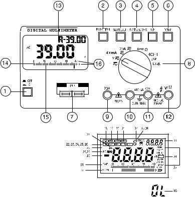
5.4.1 Operating elements
1.Device on/off
2.Function pushbutton
The various subfunctions, such as MIN/MAX, REL, DUAL, etc. are set using this button.
3.Set/Reset button
The instrument is reset into its basic condition with this button.
4.DC Ω / AC (•) button
This button switches the measurement from DC to AC values or, under resistance measurement, from actual resistance measurement to continuity test
5.Up button («plus» button)
6.Down button («minus» button)
7.Capacity and inductance socket
In this socket uncharged capacities and voltage-free inductances (coils, chokes, transformers, etc.) can be measured.
8.Rotary switch for setting the different operations (voltage measurement, current measurement, etc.)
9.A input socket for the measurement of DC and AC currents to 20 A max.
10.mA input:
This input is for measuring direct and alternating currents up to 400 mA max. (protected with a quick-acting 800mA fuse).
11.COM (-) input socket (COM or negative connection)
12.V-Ohm (+) input socket (= positive connection)
13.LCD display (3/4-position, highest display value: 3999)
14.Analogue bar graph
15.Bar graph line division
16.Overload «OL» display
If «OL» appears in the display, this means that the range has been exceeded
Attention!
Observe maximum input levels.
17.Auto Hold «A» in front of the small display
18.Data Hold
Data Hold «freezes» the measured value.
19.MIN = Minimum
As soon as this symbol appears in the display, the lowest-measured value at any given time is displayed, for example during discharge of rechargeable cells.
20.MAX = Maximum
As soon as this symbol appears in the display, the highest-measured value at any given time is displayed, e.g. during overvoltage.
21.REL = Relative
22.MEM = Memory
23.RCL = Recall = of stored measured value
24.R-H = Range Hold = Auto Range switched off, manual range{723} selection, excluding CAP capacity measuring range.
25.EXT = External
With this function, two different operating modes can be read simultaneously, e.g. the secondary voltage of a transformer < 125 VAC rms and AC power frequency
26.CMP = Comparison
27.»  » = Inductance
28.AC = AC voltage or current
29.(•) = Symbol for acoustic continuity tester
30.«-« = Minus sign and symbol for negative polarity
31.CAP = Capacity ==> measurement of capacitors
32.LOGI = Logic test
When the logic test function is selected, this symbol appears in the display
33.Second «small» display for the DUAL display function
34.= Battery symbol
If this symbol appears in the display, the battery must be changed.
35.Various measurement units
36.Reference number: indicating the memory location numbering for the MEM and RCL (=Recall) functions
5.4.2. Using the multimeter
A) Fitting the battery — changing the battery
So that the measuring instrument functions perfectly, it must be fitted with a 9V battery. When the battery change symbol appears in the display (after approx. 60 hours of operation) the battery must be replaced. To do this, proceed as follows:
The battery compartment is located beneath the upper cover (on the rear of the case) which is secured with two screws, left and right.
Attention!
Remove the MS-9160 without fail from all circuits being measured before changing the battery.
Always switch off the instrument with the main switch (POWER), which is located in the control area of the DC voltage power supply.
Only when it is certain that the MS-9150 is disconnected from AC
power and from all circuits should changing the battery be begun. Screw out both crosshead screws carefully with a suitable screwdriver and remove the cover cautiously. Remove the used battery (9 V). It is connected with a battery clip. Remove this carefully from the old battery and connect the clip to a fresh, unused battery observing the polarity. Push the battery into the battery compartment to the stop and screw the cover carefully up again.
Attention!
Do not under any circumstances operate the measuring instrument when it is open! Danger to life!
Leave no used battery in the measuring instrument, because even leakproof batteries can corrode and thereby release chemicals, which can endanger health and destroy the battery compartment. Used batteries are to be considered as special waste and must therefore be disposed of without putting the environment at risk. Special collection containers are provided for this purpose by specialist dealers and in scrap yards.
Switch the measuring instrument off when it is no longer required.
B) Connecting the test leads
Always use only the supplied test leads for making measurements. Before each connection note the condition of the connecting plug and test probes and check the insulation for damage.
These test leads are intended for voltages up to 1000 V max. The measuring instrument is similarly designed for voltages up to 1000 VDC and 750 VAC rms max. Take particular care when dealing with voltages greater than 25 V AC or 35 V DC.
Attention!
Never exceed the maximum input amplitudes, because danger to life can arise under adverse conditions.
C) Putting into service
C.1 Basic settings
Press the ON button (1). The display is now illuminated. To select a function, rotate the operating mode switch to the desired position. «Normal» measurements can now be performed without additional func-
tions.
To select such an additional function, press the FUNCTION (2) button. By the repeated pressing of this button the various subfunctions are displayed in the display. To exit from the menu, press the Set/Reset button twice: once sets the subfunction, twice resets it.
C.2 Button configuration
a)The ON/OFF button switches the measuring instrument both on and off: if the button is pressed once, the instrument is switched on; if it is pressed a second time, it is switched off.
After approx. 8 minutes of «zero use», when the display hardly changes (with open test leads), the Auto Power Off function switches the multimeter off, to save energy. The multimeter must then be switched off and on again.
b)FUNCTION
The A-H symbol appears in the display as soon as the instrument is switched on. Press the «FUNCTION» button to call the subfunctions. The following symbols appear in the display as a result: D-H -> MIN -> MAX -> REL -> CMP -> R-{783}H -> EXT -> MEM -> RCL
c)Set/Reset
To activate, i.e. switch on, a selected subfunction, press this button once.
Press the button once to return to the basic setting again (Reset).
d)DC/Ohm/AC (•)
When the operating mode switch is set to voltage or current measurement, press this button to switch from DC voltage measurement to AC voltage measurement. When the measurement function switch is set to (•), this button must also be pressed to switch from acoustic continuity test to resistance measurement.
e)UP / DOWN
Press one of these buttons to set the reference value in the REL or CMP subfunctions and to address the stored value in the MEM or RCL (Recall Memory) subfunctions.
C.3 Connector and socket configuration
a)Sockets for capacity or inductance measurement
Insert the (discharged!) capacitor observing polarity or the voltagefree inductance (coil) into the sockets. Ensure that the connections are long enough, because otherwise incorrect measurements can
occur.
b) Operating mode switch = measurement function switch (8)
Attention!
The operating mode switch may not be moved during measurements, because otherwise the measuring instrument can be destroyed and as a result danger to life can occur.
Arranged in a semi-circle, the various basic measurement ranges selectable by rotating the switch are:
|
mV |
= millivolt AC/DC (milli = 10 exp.-3) |
|
|
V |
= |
Volt AC/DC |
|
400mA |
= |
milliampere AC/DC |
|
20A |
= |
Ampere AC/DC |
(@)= Continuity test
|
W |
= |
Resistance measurement |
|
mH |
= |
Inductance measurement |
|
CAP |
= |
Capacity measurement |
|
LOGIC |
= |
Logic test |
c)20 A socket
For DC or AC current measurements up to 20 A max.(!), the red test lead must be plugged in here.
Attention!
When measuring current,the operating mode switch must never be set to voltage (mV or V) or to any other switch position other than current measurement (mA or A).
d)mA socket
The red test lead must be plugged in here for DC or AC current measurements to 400 mA max!, but only when the operating mode switch is set to «400mA».
e)COM = common socket
Except for capacity and inductance measurements, the black test lead must be plugged in here for all measurements (common socket means minus, «-» or ground socket)
f)V/Ohm socket
The red test lead must be plugged into this socket when voltage or resistance measurements, continuity check or logic tests are performed.
C.4 Explanation of display and symbols
a)Digital display
The display can show up to «3999» and the polarity (-) is automatically displayed (for negative voltages and reversed polarity). Additionally there are three decimal point positions.
b)Analogue bar graph
The analogue bar graph consists of 43 segments. It has a higher speed of measurement than the digital display. Measured value trends are thus more easily recognised. If the measurement range is exceeded, «OL», for Overload will be displayed and the display «flashes» in warning.
c)Auto Hold and Dual Display «d»
The Auto Hold function is active for DC voltage, current, resistance, and capacity (CAP) measurements and continuity test. The measured value, visible in the «large» display 4 — 5 sec. beforehand, is displayed in the small display. The Auto Hold function itself is indicated with the letter «A» in front of the small display. «d» for Dual Display appears left in front of the small display, when an AC voltage (ACV) or logic (LOGIC) measurement is carried out. The following table shows which measurements / indications are possible:
|
Measuring function |
Main display |
Subdisplay |
||
|
(Large display) |
(Small display) |
|||
|
AC voltage |
AC voltage |
dB(m) |
||
|
Logic measurement |
Hi/Lo |
DC voltage |
||
d)Data-Hold «D-H»
With D-H a measured value is frozen (held).
e)MIN (= Minimum)
Press this button once: the smallest measured value is displayed on the second-(DUAL)display, while measurements continue with the «normal» display.
f)MAX (= Maximum)
Press the Set/Reset button once: the highest measured value is now displayed on the second display, while measurements continue with the large display.
g)REL (= Relative)
This setting permits the comparison of a reference value with a subsequent measured value. Proceed as follows:
1.First press the «Function» button until «REL» appears in the display.
2.Now set the polarity of the reference value, the reference value and the measurement range with the «UP» and «DOWN» buttons. After each input the SET/RESET button must be pressed once in confirmation.
|
Button operation sequence: |
||
|
=> Function => Display «REL» => |
||
|
=> Setting ± (with UP-/DOWN buttons) |
=> SET/RESET |
=> |
|
=> Setting first position |
=> SET/RESET |
=> |
|
=> Setting 2nd position |
=> SET/RESET |
=> |
|
=> Setting 3rd position |
=> SET/RESET |
=> |
|
=> Setting 4th position |
=> SET/RESET |
=> |
=> Setting the measurement range (no automatic range change) => SET/RESET =>
=> The small display displays the reference value
The measuring instrument will now show the difference between the stored value and the subsequently-measured value on the small display, while the actual value presently being measured can be read on the large display.
Example:The reference value is 100.0 V; the present (large display) reading shows 90 V. On the small display the difference of -10 V can be read. Should the next measured value be 100.0 V, the differ. will be «0». The small display then reads 0000. The display can display 3999 max.
Attention!
With the REL function, RESET using the SET/RESET button is not possible. To exit this function, press either the measurement function switch or the FUNCTION button or one of the other buttons.
h)MEM (= Memory)
With this special function up to 8 reference values can be stored, except under temperature measurement. For this, proceed as follo-
ws:
1.Press the function button until MEM appears in the display,
2.Press the UP/DOWN button, to set a reference number between 0 and 4,
3.Press the Set/Reset button, to store the value.
When several reference values are «filed» under the same reference number, the previous value will be overwritten in each case.
i)RCL (= Memory Recall)
This function reads the stored reference value from the memory.
Proceed as follows:
1.Press the UP or DOWN button to select the desired reference number,
2.Now press the Set/Reset button to read out the stored value. The
read-out value is shown on the small display.
k)R-H = Range Hold
With this function it is possible to exit the Auto Range mode and to set/determine the measurement range in the selected operating mode (voltage, current, resistance, etc. measurement) by pressing the UP and DOWN buttons manually. This function is not available while measuring capacity (CAP).
l)EXT (= External)
With this function two different operating modes can be read simultaneously, one on the large display, one on the small display. Note the following table in this connection:
|
Operation mode |
Main display |
Subdisplay |
||
|
AC voltage |
AC voltage |
Frequency change-over |
||
|
Logic measurement |
Hi/Lo |
Frequency change-over |
||
m)CMP (= Comparison)
In this subfunction a high/low comparison can be made, in which the highest and lowest stored reference values can be compared with the presently-measured value. To exit from this function, briefly press the operating mode switch. First set the desired measurement range. Then proceed according to the following examples:
Button operation sequence
|
=> FUNCTION |
=> display «CMP» and «MIN» => |
|
|
=> set polarity +/- (Up/Down) |
=> SET/RESET |
=> |
|
=> set 1st position |
=> SET/RESET |
=> |
|
=> set 2nd position |
=> SET/RESET |
=> |
|
=> set 3rd position |
=> SET/RESET |
=> |
|
=> set 4th position |
=> SET/RESET => |
|
|
=> display «CMP» and «MAX» |
=> |
|
|
=> set +/- |
=> SET/RESET => |
|
|
=> set 1st position |
=> SET/RESET => |
|
|
=> set 2nd position |
=> SET/RESET => |
|
|
=> set 3rd position |
=> SET/RESET => |
|
|
=> set 4th position |
=> SET/RESET => |
=> display of «CMP», «MIN» or «MAX» and «LO» or «HI» or «PASS» in the small display
=> the instrument is ready for comparison measurement.
Note!
With the High/Low logic function the CMP function is inoperable.
n)Display for the reference number
The reference number is applicable to the MEM and RCL functions. The numbers are called by pressing the UP (+1) or DOWN (-1) buttons.
C.5 Display information and symbols about operating modes
a)» » Inductance measurement
The measurement range covers from 0.01 mH to 400 mH max.
b)(•) Continuity test
The continuity of voltage-free wiring, plug connections or fuses can be checked with this function acoustically and optically (display of measured value).
c)«-« Negative polarity
With reversed test leads and with negative polarity, a «-» sign appears in front of the measured value.
d)CAP Capacity measurement
The capacity measurement range enables measurements of discharged capacitors from 4 nF to 400 µF
e)LOGIC logic test
All logic levels can be measured and displayed with this function.
f)Battery change indicator
An alkaline 9 V battery has an average life of approx. 60 hours in this measuring instrument. About 8 hours before the battery end of
life, the battery change symbol appears in the display.
A battery check is carried out each time between individual measurement cycles.
g) all other symbols, which stand for the various measurement units:
|
AC |
= |
AC units |
|
DC |
= |
DC units |
|
mV |
= |
millivolt (exp.-3) |
|
V |
= |
Volt |
|
mA |
= |
milliampere (exp.-3) |
|
A |
= |
Ampere |
|
kHz |
= |
kilohertz (exp.3) |
|
uF |
= |
microfarad (exp.-6) |
|
nF |
= |
nanofarad (exp.-9) |
|
mH |
= |
milliHenry (exp.-3) |
|
uH |
= |
mikroHenry (exp.-6) |
|
W |
= |
Ohm |
|
kW |
= |
kiloohm (exp.3) |
|
MW |
= |
Megaohm (exp.6) |
5.4.3 Performing measurements A) Voltage measurement
Attention!
Under no circumstances exceed the maximum permitted input amplitude. 1000 VDC max. and 750 VAC rms max.
Touch no circuits or components when voltages greater than 25 VAC rms or 35 VDC are present.
To measure DC or AC voltages, proceed as follows:
1.Set the rotary switch to the desired position (mV or V)
2.Connect the red test lead to the V/Ohm socket (+) and the black test lead to the COM socket (-)
3.Press the DC/AC button according to whether DC or AC voltage is to be measured. As soon as «AC» appears in the display, the AC voltage measurement range is set.
4.Connect the test probes to the points of measurement (load, circuit, etc.).
Each of the five voltage ranges, whether AC or DC, has an input impedance of 10 MOhm in parallel with 100 pF. The AC voltage input is ACcoupled. As soon as a «-«-sign appears in front of the measured value under DC voltage measurements, the measured voltage is negative (or the test leads reversed).
B) Current measurement
To measure direct or alternating currents, procedure is as follows:
1.Set the rotary switch to current measurement (400mA or 20A).
2.Connect the red test lead to the mA socket when currents up to 400 mA max. are to be measured and to the A socket for currents up to 20 A max.
3.Press the DC/AC button according to whether DC or AC current is now to be measured.
As soon as «AC» appears in the display, the AC current measurement range is set.
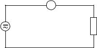
4.Connect the instrument leads in series with the test object (see figure below).
Attention!
Do not measure any currents in circuits in which voltages greater than 250 VDC or VAC rms can occur. Under no circumstances should currents over 20 A be measured. Measurements should only be made in 16Afused current circuits or those in which powers greater than 4000 VA cannot occur. Measurements of currents equal to 20 A must only be measured for a maximum of 30s duration and must only be performed at intervals of 15 minutes (cooling down phase for the shunt).
|
A DMM |
||
|
Current |
Consuming |
|
|
device, |
||
|
source |
||
|
load, circuit |
||
C) Continuity test
With this function voltage-free leads, fuses, circuits etc. can be acoustically checked for continuity. This measurement is performed as follows:
1.Position the rotary switch to (•).
2.Connect the red test lead to the V/Ohm socket (+) and the black test lead to the COM socket (-).
3.Then connect the test probes to the points of measurement.
Attention!
Measure no charged capacitors, because otherwise the measuring instrument can be destroyed by a possible discharge.
D) Resistance measurement
Attention!
Ensure that all components, circuits, chips and other objects to be measured, are completely voltage-free.
1.Set the measurement function switch to resistance measurement (OHM).
2.Connect the red test lead to the V/Ohm socket (+) and the black test lead to the COM socket (-).
3.Now connect the measuring probes with the test object.
The resistance of the test leads can normally be ignored (approx. 0.1 to 0.2 Ohm). However, this low value can lead to inaccuracies in the lowest measurement range.
Using the «REL» function, this resistance can be «subtracted» to compensate for these «measurement errors», i.e. the display referenced and set to «0».
When a resistance measurement is performed, ensure that the test points which you touch with the test probes during measurement are free from dirt, oil, solder flux or similar. Such conditions can falsify the measured value.
With resistances greater than approx. 4 MOhm the display can require some time to become stabilised.
As soon as «OL» appears in the display and the bar graph flashes, the measurement range has been exceeded and the measurement path is interrupted.
E) Inductance measurement
For the measurement of inductance proceed as follows:
1.Set the rotary switch to «400 mH».
2.Measurements can now be performed with the test socket on the measuring instrument. The «R-H» function can be used to switch to and fro manually between two measurement ranges. If the «R-H» function is not set, the measuring instrument automatically sets itself to Auto Range.
Attention!
With inductance measurements, make sure without fail that the coil and the circuit, to which it may be connected, is absolutely voltage-free. Any capacitors present must be discharged.
F) Capacity measurement
For the measurement of capacities proceed as follows:
1.Discharge each capacitor before connecting it to the measuring instrument.
Attention!
When short-circuiting capacitors, high-energy discharges can occur. Caution: danger to life!! Do not touch capacitor connections with voltages greater than 35 VDC and 25 VAC. Take care in environments in which dust, inflammable gas, steam or liquids are present or can occur. ==> Danger of explosion!
2.Set the measurement function switch (8) to «CAP».
3.Measurements can now be performed with the test socket on the measuring instrument.
With polarised capacitors, observe the correct polarity.
G) Using the analogue bar graph
The bar graph is easy to operate and understand. It is comparable with
the pointer of an analogue measuring instrument but without its mechanical disadvantages. It is particularly suitable for quickly-chan- ging signals, for which the digital display is too «slow». Trends in a changing measurement value can thereby be quickly recognised and evaluated. During overrun or when the measurement range is exceeded, all bar graph display segments flash.
H) Logic test
This measurement function indicates logic levels in digital circuits.
1.Switch the measuring instrument on.
2.Set the measurement function switch (8) to HIGH/LOW. «rdY» (ready) appears in the display.
3.Connect the test leads to the COM socket (black lead) and to the V/Ω socket (red lead).
4.Now connect the other end of the black test lead to the digital circuit»ground» = «-» (normally). The red test probe must be connected to the positive supply voltage (V+ or Vcc).
5.When the connections are made, press the Set/Reset button once.
6.While the black test lead remains connected to ground, the red test probe can be removed from the positive supply. The test points under consideration can now be touched with the red test probe; as a result the multimeter will display three possibilities.
—If the level is more than 70 % of the stored supply voltage, «Hi» will be displayed;
—If the level is less than 30 % of the stored supply{1215} voltage, «Lo» will be displayed;
—If the level on the contrary is between = 31 % and 69 % of the stored supply voltage (e.g. 5 V), «—» will be displayed.
In the «LOGIC» operating mode, it is not possible to use the subfunctions «MAX», «MIN» and Data Hold = «D-H». Before using the measurement range switch when leaving the logic function, -the SET/RESET button must be pressed, so that «rdY appears» in thedisplay.
I) Using the multimeter in connection with a computer
a)Connection
Connect the RS-232 interface cable (null modem cable) to the multimeter (rear of the case under the lower cover) and to a serial interface of the computer.
Now switch on the measuring instrument.
b)Using the software
This multimeter operates with any computer with an RS-232 interface, but the software is only suitable for IBM-compatible computers. Using the software is described as follows:
1.Insert the floppy disk into the drive. Copy the files either onto the hard drive or make a back-up copy of the floppy.
2.Press the «Enter» key.
3.To stop or interrupt the program during execution, press CRTL + BREAK on the computer keyboard.
Data transfer
SAs soon as the multimeter is switched on, the interface is ready. Data transfer is started by command [D] from the computer.
The following should be noted, when software other than that provided is used.:
The data format is 14 bits in length. It is composed as follows:
|
BYTE 1 2 3 4 5 6 |
7 8 9 A B C D E |
||
|
Example 1 |
DC |
— 3 , 9 9 9 V |
CR |
|
Example 2 |
OHM |
3 , 9 9 9 M o h m CR |
Program example in BASIC for easy reading of the multimeter:
10 OPEN «COM1:1200,N,7,2,RS,CS,DS,CD» AS#2
20 A$=»D»
30 PRINT #2,A$;
40 IN$=INPUT$(14,#2)
50 PRINT IN$
60 CLOSE #2
70 END
Specific data transfer characteristics (communication parameters):
|
Transfer rate |
: |
1200 baud |
|
Character code |
: |
7-bit ASCII |
|
Parityt |
: |
none |
|
Stop bits |
: |
2 |
5.5 Maintenance and calibration
Соседние файлы в папке stud
- #
- #
![]()
METEX MS-9150 SM

Type:  (PDF)
(PDF)
Size
392.5 KB
Page
6
Category
METER
SERVICE MANUAL
If you get stuck in repairing a defective appliance
download
this repair information for help. See below.
Good luck to the repair!
Please do not offer the downloaded file for sell only
use it for personal usage!
Looking for similar metex manual?
Document preview [1st page]

Click on the link for free download!
Document preview [2nd page]

Click on the link for free download!
Please tick the box below to get download link:
- Also known:
METEX MS-9150 MS9150 MS 9150
- If you have any question about repairing write your question to the Message board. For this no need registration.
- Please take a look at the below related repair forum topics. May be help you to repair.
Warning!
If you are not familiar with electronics, do not attempt to repair!
You could suffer a fatal electrical shock! Instead, contact your nearest service center!
Note! To open downloaded files you need acrobat reader or similar pdf reader program. In addition,
some files are archived,
so you need WinZip or WinRar to open that files. Also some files are djvu so you need djvu viewer to open them.
These free programs can be found on this page: needed progs
If you use opera you have to disable opera turbo function to download file!
If you cannot download this file, try it with CHROME or FIREFOX browser.
Relevant METER forum topics:
Sziasztok!
Ma kaptam ezt a címben említett műszert, ez egy nagy előre lépés volna a kínai DT9205A-hoz képest, amit eddig használtam. A műszer előéletéről nem sokat tudok, találtam róla egy rövid leírást, ahol a főbb funkcióit összefoglalták, gyors tesztet követően úgy tűnik, hogy minden funkciója jól működik, viszont elsőre engem nagyon idegesít, hogy minden funkcióváltáskor «csippan» egyet, valamint az sem tetszik, hogy a zárlat jelző üzemmódban szaggatott csipogó jelet ad (hogy lehet ezzel pl. kábel kontakt hibát indikálni?), van erre valami orvoslat vagy meg kell tanulni együtt élni ezzel?
Sziasztok
Segítséget szeretnék kérni, gyakorlottabb kollégáktól.
Van egy METEX M4650 műszerem .
Dióda állásban nem mér és 1116.8mV -ot mutat . Szakadásvizsgáló viszont jelez, ha összeérintem a műszerzsinórt.
Van rajz itt a Tanyán de azon nehéz eligazodni.
Ha tudtok segítsetek.
Köszi
Szabi
Tisztelt Mesterek!
Tegnap megadta magát a tápom.
Metex ( Voltcraft ) MS-9160, kapcsolás a mellékletben.
Az egyik áteresztő, totál zárlatos lett.
Egy féléve már mindezt megtette.
Akkor simán cseréltem és nem is zsörtölődtem , mivel a tranzisztor, szó szerint nem volt leszorítva.
Gondoltam hanyag emberke szerelte ,vagy ami nem lehetséges , de megfordult a fejemben , hogy remegés , vagy hőtágúlás miatt kilazult.
De ennyire mégsem.
Most egy rövidzár és pukk . Megjelent a kimeneten a 40V.
Szerencse hogy egy egyszerű autórádiót javítottam , és csak a puffer pukkant szét.
Csere , minden működik rendesen.
Van egy másik is és összehasonlítva is néztem, de ha valami nem kerülte el a figyelmem , akkor minden jó.
Ami a különbség a rajztól , hogy mindkettőben 741 IC van.
Zárlati áramot beállítva ,(3A), rövid idő alatt igencsak melegszik az áteresztő , pedig rendes hűtése van.
Régi tápom túlélte a modúl TV korszakot , órákig járatva róla melegedés nélkül.
Igaz abban TO3 tokos 2db KD502 van.
Biztos jobb lenne a TO 3 tok , de nem bántanám ha nem muszáj.
Tranzisztor: D-718 ( KTD-718) NPN NF/S-L 120V 8A 80W/12MHz.
Eredetiek mind jók, KTD-k , gondolom jobb lenne 2SD718.
Mi a vélemény a kapcsolásról?
Mivel lehetne( jobbal) helyettesíteni?
Van pár eredeti Toshiba : 2SD-1047 , 2SA1694 .
Menyit segítene egy autó erősítőben használatos leszorítás megoldás , vagy szilikon szigetelőt csillámra cserélni?
Minden ötletet és tanácsot örömmel fogadok.
Tisztelettel: Öreg T.
Táp megoldva, remélve tartósa.
Sziasztok!
Keresem a (sárga) M-3650-es rajzát! A 3650D nem jó, az egy másik műszer!
Segítségetek előre is köszönöm!
Leiszt Jani
Similar manuals:
If you want to join us and get
repairing help
please sign in or sign up by completing a simple electrical test
or write your question to the Message board without registration.
You can write in English language into the forum (not only in Hungarian)!
E-Waste Reduce
Продам измерительный комплекс Metex MS-9150 бу в отличном состоянии.
Комплексное решение для лаборатории
цифровой мультиметр
функциональный генератор
универсальный частотомер
источник питания
Технические характеристики MS-9150
Цифровой мультиметр:
Индикатор 3¾ разряда (max. 3999) с подсветкой
Основной и один вспомогательный дисплей + линейная шкала
Режим сохранения данных
Сохранение максимального и минимального значения
Память на 5 значений
Подключение к компьютеру через порт RS-232C
Функциональный генератор:
Выходной сигнал: синус, прямоугольный, треугольный, импульсный, прямоуг. TTL уровня
Частота: 0.02 Гц … 2 Мгц , 7 диапазонов
Выходное напряжение ампл.: 1 … 10 В на нагрузке 50 Ом
Выходной импеданс = 50 Ом или 600 Ом по выбору
Аттенюатор -20 дБ
Внутреннее и внешнее свипирование сигнала, период 20 мc … 2 c
Универсальный частотомер:
Пределы измерений: каналы А и В – 5 Гц … 100 МГц , канал С – 100 МГц … 1.3 ГГц
Входное напряж.: каналы А и В – 5 Гц … 100 МГц, аттенюатор: ×1, ×20, канал С – 150 мВ
Входное напряжение мах 3 В
Период измерения 0.1 с 4 10 с
Источник питания:
Выход 1: 0 … 30 В, 0 … 2 А, стабилизация напряжения и тока
Выход 2: 5 В фиксировано, 2 А
Выход 3: 15 В фиксировано, 1 А
Дисплей 3½ разряда с подсветкой
Ярославль |
10 февраля 2019, номер: 28203822, просмотры: 240
!
Автоматический перевод может быть не точным! Если Вы не уверены в
правильности перевода обратитесь к нашей команде
поддержки.
![]()
![]()
![]()
![]()
SPRZEDAJĘ DOKŁADNIE TO CO WIDAĆ
PO POBIEŻNYM SPRAWDZENIU WSZYSTKIE FUNKCJE URZĄDZENIA DZIAŁAJĄ PRAWIDŁOWO
OPRÓCZ BRAKU 5V Z ZASILACZA .JEST 15V I NAPIĘCIE REGULOWANE 0-30V DZIAŁA PRAWIDŁOWO
Z RACJI WIEKU URZADZENIA SPRZEDAJĘ BEZ GWARANCJI
Мы доставляем посылки в г. Калининград и отправляем по всей России
-
1
Товар доставляется от продавца до нашего склада в Польше. Трекинг-номер не
предоставляется. -
2
После того как товар пришел к нам на склад, мы организовываем доставку в г. Калининград.
-
3
Заказ отправляется курьерской службой EMS или Почтой России. Уведомление с трек-номером вы
получите по смс и на электронный адрес.
!
Ориентировочную стоимость доставки по России менеджер выставит после
оформления заказа.
Гарантии и возврат
Гарантии
Мы работаем по договору оферты, который является юридической гарантией того, что мы выполним
свои обязательства.
Возврат товара
Если товар не подошел вам, или не соответсвует описанию, вы можете вернуть его, оплатив
стоимость обратной пересылки.
- У вас остаются все квитанции об оплате, которые являются подтверждением заключения сделки.
- Мы выкупаем товар только с проверенных сайтов и у проверенных продавцов, которые полностью отвечают за доставку товара.
- Мы даем реальные трекинг-номера пересылки товара по России и предоставляем все необходимые документы по запросу.
- 5 лет успешной работы и тысячи довольных клиентов.
Купить Комплект измерительный METEX MS-9150 по выгодной цене 20 009 ₽ с доставкой из Польши в Калининград,
по России и в страны СНГ, вы можете на сайте Aredi! Мы доставляем Мультиметры из Allegro и
других магазинов Польши!
Manuals for metex instruments ms-9150 to download for viewing them online or printout as PDF
The user should refer to the operation manual to protect the instrument …..
available in the range of 0.2Hz to 100KHz(MS-9150), 1Hz to 100KHz(MS-9160).
4-3.
Aug 24, 2015 … Read about ‘Humble LAB equipment: METEX MS-9150 4-in-1 Test Setup’ on
element14.com. Real estate is at a premium in the lab. I don’t …
M3860D · Metex. Hand Held Multimeter, 3 3/4 Digits Dual Display. List Price: $0
… MS9150 · Metex. Universal Test System. List Price: $565 …
MS-9150, Frequency Counter: 1Hz to 20MHz (CH A), 20MHz to 2.7GHz (CH B) …
and measurement of Microwave devices, Experiment and Operation Manuals …
20. Apr. 2015 … Die Softwareunterstützung bleibt — so wie sie ist — erhalten. ABACOM ….. MS 9150
. COM. DMM. 1. 1. 1. 1. MS 9160. COM. DMM. 1. 1. 1. 1. MS- …
lelism. Cubic samples were extracted using manual saw and then polished with
fine … generator Metex MS-9150 giving sinusoidal signal of prescribed frequency
, two ana— … Model 5058 PR and Link Instruments digital storage oscilloscope.
« Previous —
Page 1
— Next »
Which manuals are you looking for?
Комплексное решение для лаборатории


Подробное описание
- цифровой мультиметр
- функциональный генератор
- универсальный частотомер
- источник питания
в одном корпусе
- Габариты 370 × 375 × 165 мм
- Вес 15 кг
SPRZEDAJĘ DOKŁADNIE TO CO WIDAĆ
PO POBIEŻNYM SPRAWDZENIU WSZYSTKIE FUNKCJE URZĄDZENIA DZIAŁAJĄ PRAWIDŁOWO
OPRÓCZ BRAKU 5V Z ZASILACZA .JEST 15V I NAPIĘCIE REGULOWANE 0-30V DZIAŁA PRAWIDŁOWO
Z RACJI WIEKU URZADZENIA SPRZEDAJĘ BEZ GWARANCJI
Мы доставляем посылки в г. Калининград и отправляем по всей России
-
1
Товар доставляется от продавца до нашего склада в Польше. Трекинг-номер не
предоставляется. -
2
После того как товар пришел к нам на склад, мы организовываем доставку в г. Калининград.
-
3
Заказ отправляется курьерской службой EMS или Почтой России. Уведомление с трек-номером вы
получите по смс и на электронный адрес.
!
Ориентировочную стоимость доставки по России менеджер выставит после
оформления заказа.
Гарантии и возврат
Гарантии
Мы работаем по договору оферты, который является юридической гарантией того, что мы выполним
свои обязательства.
Возврат товара
Если товар не подошел вам, или не соответсвует описанию, вы можете вернуть его, оплатив
стоимость обратной пересылки.
- У вас остаются все квитанции об оплате, которые являются подтверждением заключения сделки.
- Мы выкупаем товар только с проверенных сайтов и у проверенных продавцов, которые полностью отвечают за доставку товара.
- Мы даем реальные трекинг-номера пересылки товара по России и предоставляем все необходимые документы по запросу.
- 5 лет успешной работы и тысячи довольных клиентов.


