Quick Start
Thank you for purchasing the MSI® MAG B460 TORPEDO motherboard. This Quick Start section provides demonstration diagrams about how to install your computer. Some of the installations also provide video demonstrations. Please link to the URL to watch it with the web browser on your phone or tablet. You may have even link to the URL by scanning the QR code.
Kurzanleitung
Danke, dass Sie das MSI® MAG B460 TORPEDO Motherboard gewählt haben. Dieser Abschnitt der Kurzanleitung bietet eine Demo zur Installation Ihres Computers. Manche Installationen bieten auch
die Videodemonstrationen. Klicken Sie auf die URL, um diese Videoanleitung mit Ihrem Browser auf Ihrem Handy oder Table anzusehen. Oder scannen Sie auch den QR Code mit Ihrem Handy, um die URL zu öffnen.
Présentation rapide
Merci d’avoir choisi la carte mère MSI® MAG B460 TORPEDO. Ce manuel fournit une rapide présentation avec des illustrations explicatives qui vous aideront à assembler votre ordinateur. Des tutoriels vidéo sont disponibles pour certaines étapes. Cliquez sur le lien fourni pour regarder la vidéo sur votre téléphone ou votre tablette. Vous pouvez également accéder au lien en scannant le QR code qui lui est associé.
Быстрыйстарт
Благодарим вас за покупку материнской платы MSI® MAG B460 TORPEDO. В этом разделе представлена информация, которая поможет вам при сборке комьютера. Для некоторых этапов сборки имеются видеоинструкции. Для просмотра видео, необходимо открыть соответствующую ссылку в веб-браузере на вашем телефоне или планшете. Вы также можете выполнить переход по ссылке, путем сканирования QR-кода.
Quick Start I

|
Installing a Processor/ Installation des Prozessors/ Installer un |
||
|
processeur/Установкапроцессора |
2 |
|
|
1 |
||
3
6


 8
8
II Quick Start
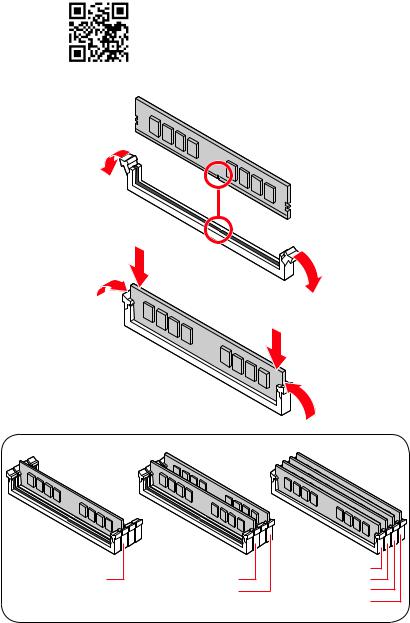
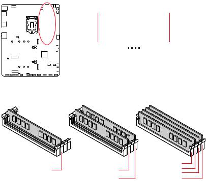
Installing DDR4 memory/ Installation des DDR4-Speichers/
InstallerunemémoireDDR4/УстановкапамятиDDR4
|
DIMMA2 |
DIMMA2 |
DIMMA1 |
|
DIMMA2 |
||
|
DIMMB2 |
DIMMB1 |
|
|
DIMMB2 |
Quick Start III
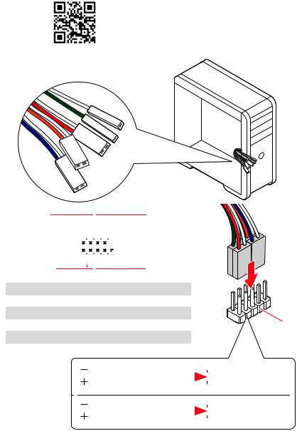
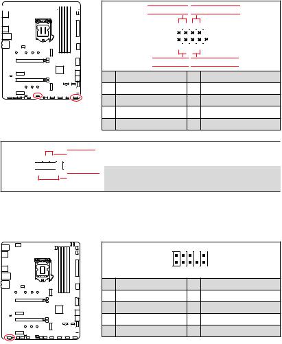
Connecting the Front Panel Header/ Anschließen der Frontpanel-Stiftleiste/ Connecter un connecteur du panneau avant/Подключениеразъемовпереднейпанели
|
— |
|||
|
LED |
|||
|
LED+ |
POWER |
||
|
POWER |
|||
|
LED |
|||
|
SW |
HDD |
||
|
POWER |
|||
|
SW |
|||
|
RESET |
|
Power LED |
Power Switch |
||||||||||||||||||||
|
-+-+ |
|||||||||||||||||||||
|
JFP1 |
2 |
10 |
|||||||||||||||||||
|
1 |
9 |
Reserved |
|||||||||||||||||||
|
+ +— |
|||||||||||||||||||||
|
HDD LED |
Reset Switch |
||||||||||||||||||||
|
1 |
HDD LED + |
2 |
Power LED + |
||||||||||||||||||
|
3 |
HDD LED — |
4 |
Power LED — |
||||||||||||||||||
|
5 |
Reset Switch |
6 |
Power Switch |
||||||||||||||||||
|
7 |
Reset Switch |
8 |
Power Switch |
||||||||||||||||||
|
9 |
Reserved |
10 |
No Pin |
HDDLED RESETSW
|
HDD LED — |
|||||||
|
HDD LED |
|||||||
|
HDD LED + |
|||||||
|
POWER LED — |
|||||||
|
POWER LED |
POWER LED + |
||||||
IV Quick Start
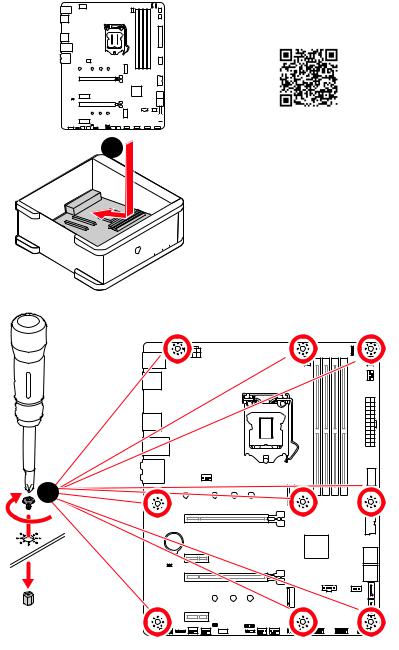
Installing the Motherboard/ Installation des Motherboards/
Installerlacartemère/Установкаматеринскойплаты
1
BAT1
*3 kgf·cm = 0.3 N·m = 2.6 lbf·in
Quick Start V
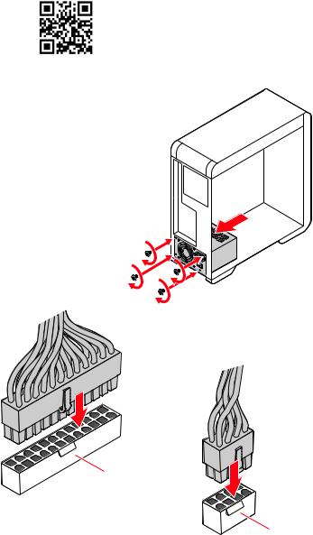
Connecting the Power Connectors/ Stromanschlüsse anschliessen/ Connecter les câbles du module d’alimentation/
Подключениеразъемовпитания
ATX_PWR1
CPU_PWR1
VI Quick Start
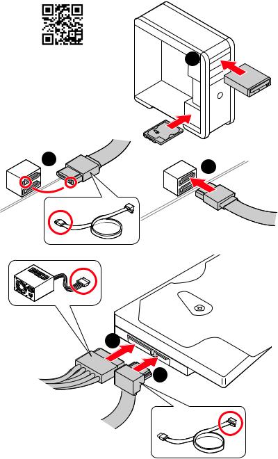
Installing SATA Drives/ Installation der SATA-Laufwerke/
InstallerledisquedurSATA/УстановкадисковSATA
|
1 |
5
4
Quick Start VII
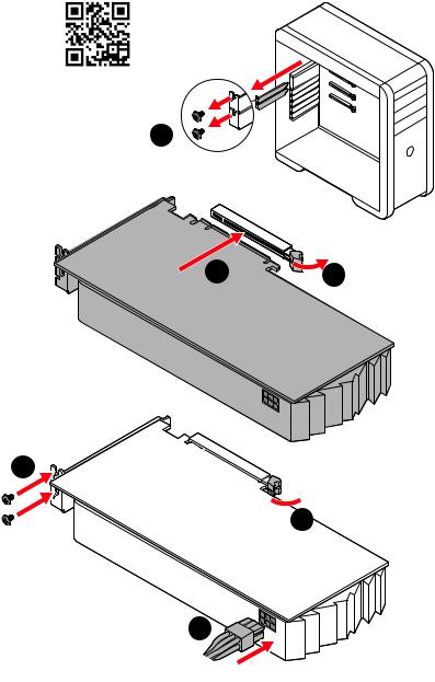
Installing a Graphics Card/ Einbau der Grafikkarte/ Installer unecartegraphique/Установкадискретнойвидеокарты
1
5
 4
4
6
VIII Quick Start
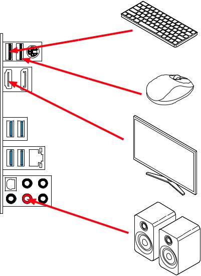
Connecting Peripheral Devices/ Peripheriegeräte/ Connecter unpériphériqueanschliessen/Подключениепериферийных устройств
Quick Start IX
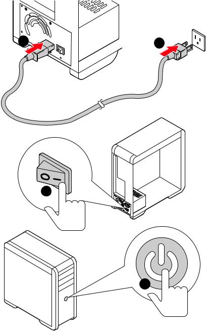
PowerOn/Einschalten/Mettresous-tension/Включение питания
1


 2
2
3
4
X Quick Start
|
Contents |
|
|
Safety Information……………………………………………………………………………………. |
3 |
|
Specifications…………………………………………………………………………………………… |
4 |
|
Package contents……………………………………………………………………………………… |
9 |
|
Rear I/O Panel………………………………………………………………………………………… |
10 |
|
LAN Port LED Status Table……………………………………………………………………….. |
10 |
|
Audio Ports Configuration…………………………………………………………………………. |
10 |
|
Realtek Audio Console……………………………………………………………………………… |
11 |
|
Overview of Components…………………………………………………………………………. |
13 |
|
CPU Socket……………………………………………………………………………………………… |
14 |
|
DIMM Slots……………………………………………………………………………………………… |
15 |
|
PCI_E1~4: PCIe Expansion Slots……………………………………………………………….. |
16 |
|
SATA1~6: SATA 6Gb/s Connectors…………………………………………………………….. |
16 |
|
M2_1~2: M.2 Slots (Key M)………………………………………………………………………… |
17 |
|
JFP1, JFP2: Front Panel Connectors…………………………………………………………. |
19 |
|
JAUD1: Front Audio Connector………………………………………………………………….. |
19 |
|
CPU_PWR1, ATX_PWR1: Power Connectors……………………………………………….. |
20 |
|
JUSB1: USB 3.2 Gen 1 5Gbps Type-C Connector…………………………………………. |
21 |
|
JUSB2: USB 3.2 Gen 1 5Gbps Connector…………………………………………………….. |
21 |
|
JUSB3~4: USB 2.0 Connectors………………………………………………………………….. |
22 |
|
JTPM1: TPM Module Connector………………………………………………………………… |
22 |
|
CPU_FAN1, PUMP_FAN1, SYS_FAN1~6: Fan Connectors……………………………. |
23 |
|
JCI1: Chassis Intrusion Connector…………………………………………………………….. |
24 |
|
JBAT1: Clear CMOS (Reset BIOS) Jumper………………………………………………….. |
25 |
|
JTBT1: Thunderbolt Add-on Card Connector………………………………………………. |
25 |
|
JRTD3: Intel RTD3 Connector……………………………………………………………………. |
25 |
|
EZ Debug LED…………………………………………………………………………………………. |
26 |
|
LED_SW1: EZ LED Control………………………………………………………………………… |
26 |
|
JRGB1~2: RGB LED connector………………………………………………………………….. |
27 |
|
JRAINBOW1~2: Addressable RGB LED connectors……………………………………… |
28 |
|
Installing OS, Drivers & Utilities……………………………………………………………….. |
29 |
|
Installing Windows® 10……………………………………………………………………………… |
29 |
|
Installing Drivers……………………………………………………………………………………… |
29 |
|
Installing Utilities…………………………………………………………………………………….. |
29 |
Contents 1
|
UEFI BIOS………………………………………………………………………………………………. |
30 |
|
BIOS Setup……………………………………………………………………………………………… |
31 |
|
Entering BIOS Setup………………………………………………………………………………… |
31 |
|
Resetting BIOS………………………………………………………………………………………… |
32 |
|
Updating BIOS…………………………………………………………………………………………. |
32 |
|
EZ Mode………………………………………………………………………………………………….. |
34 |
|
Advanced Mode ………………………………………………………………………………………. |
37 |
|
OC Menu…………………………………………………………………………………………………. |
38 |
2 Contents
Safety Information
∙∙The components included in this package are prone to damage from electrostatic discharge (ESD). Please adhere to the following instructions to ensure successful computer assembly.
∙∙Ensure that all components are securely connected. Loose connections may cause the computer to not recognize a component or fail to start.
∙∙Hold the motherboard by the edges to avoid touching sensitive components. ∙∙It is recommended to wear an electrostatic discharge (ESD) wrist strap when
handling the motherboard to prevent electrostatic damage. If an ESD wrist strap is not available, discharge yourself of static electricity by touching another metal object before handling the motherboard.
∙∙Store the motherboard in an electrostatic shielding container or on an anti-static pad whenever the motherboard is not installed.
∙∙Before turning on the computer, ensure that there are no loose screws or metal components on the motherboard or anywhere within the computer case.
∙∙Do not boot the computer before installation is completed. This could cause permanent damage to the components as well as injury to the user.
∙∙If you need help during any installation step, please consult a certified computer technician.
∙∙Always turn off the power supply and unplug the power cord from the power outlet before installing or removing any computer component.
∙∙Keep this user guide for future reference. ∙∙Keep this motherboard away from humidity.
∙∙Make sure that your electrical outlet provides the same voltage as is indicated on the PSU, before connecting the PSU to the electrical outlet.
∙∙Place the power cord such a way that people can not step on it. Do not place anything over the power cord.
∙∙All cautions and warnings on the motherboard should be noted.
∙∙If any of the following situations arises, get the motherboard checked by service personnel:
▪▪Liquid has penetrated into the computer.
▪▪The motherboard has been exposed to moisture.
▪▪The motherboard does not work well or you can not get it work according to user guide.
▪▪The motherboard has been dropped and damaged. ▪▪The motherboard has obvious sign of breakage.
∙∙Do not leave this motherboard in an environment above 60°C (140°F), it may damage the motherboard.
Safety Information 3

Specifications
|
Supports 10th Gen Intel® Core™ and Pentium® Gold / |
|
|
CPU |
Celeron® processors for LGA 1200 socket* |
|
* Please go to www.intel.com for more compatibility information. |
|
|
* Onboard graphics output are disabled when using F SKU processors. |
|
|
Chipset |
Intel® B460 Chipset |
|
∙∙4x DDR4 memory slots, support up to 128GB* |
|
|
∙∙Intel® Core™ i7/ i9 |
|
|
▪▪Supports up to DDR4 2933 MHz |
|
|
Memory |
∙∙Intel® Core™ i5 and below |
|
▪▪Supports up to DDR4 2666 MHz |
|
|
∙∙Supports Dual-Channel mode |
|
|
∙∙Supports non-ECC, un-buffered memory |
|
|
∙∙Supports Intel® Extreme Memory Profile (XMP) |
|
|
* Please refer www.msi.com for more information on compatible memory. |
|
|
∙∙1x PCIe 3.0 x16 slot (From CPU, PCI_E1), supports x16 |
|
|
mode |
|
|
Expansion Slot |
∙∙1x PCIe 3.0 x16 slot (From PCH, PCI_E3), supports x4 |
|
mode* |
|
|
∙∙2x PCIe 3.0 x1 slots (From PCH) |
|
|
* PCI_E3 will be unavailable when installing M.2 SSD in the M2_2 slot. |
|
|
∙∙1x HDMI port, supports a maximum resolution of |
|
|
Onboard Graphics |
4096×2160 @30Hz |
|
∙∙1x DisplayPort, supports a maximum resolution of |
|
|
4096×2304 @60Hz |
|
|
Audio |
∙∙Realtek® ALC1200 Codec |
|
▪▪7.1-Channel High Definition Audio |
|
|
▪▪Supports S/PDIF output |
|
|
LAN |
∙∙1x Realtek® RTL8125B 2.5Gbps LAN controller |
|
Continued on next page |
4 Specifications

Continued from previous page
|
Intel® B460 Chipset |
|
|
∙∙6x SATA 6Gb/s ports* |
|
|
∙∙2x M.2 slots (Key M) |
|
|
▪▪M2_1 supports up to PCIe 3.0 x4 and SATA 6Gb/s, |
|
|
2242/ 2260/ 2280/ 22110 storage devices* |
|
|
Storage |
▪▪M2_2 supports up to PCIe 3.0 x4, 2242/ 2260/ 2280 |
|
storage devices** |
|
|
▪▪Intel® Optane™ Memory Ready*** |
|
|
▪▪Supports Intel® Smart Response Technology for Intel |
|
|
Core™ processors |
|
|
* SATA1 will be unavailable when installing M.2 SATA SSD in the M2_1 slot. |
|
|
** PCI_E3 will be unavailable when installing M.2 SSD in the M2_2 slot. |
|
|
*** Before using Intel® Optane™ memory modules, please ensure that you have |
|
|
updated the drivers and BIOS to the latest version from MSI website. |
|
|
RAID |
∙∙Intel® B460 Chipset |
|
▪▪Supports RAID 0, RAID 1, RAID 5 and RAID 10 for SATA |
|
|
storage devices |
|
|
∙∙Intel® B460 Chipset |
|
|
▪▪6x USB 3.2 Gen 1 5Gbps ports (4 Type-A ports on the |
|
|
back panel, 2 ports through the internal USB 3.2 Gen 1 |
|
|
USB |
connector) |
|
▪▪1x USB 3.2 Gen 1 5Gbps port (1 Type-C internal |
|
|
connector) |
|
|
▪▪6x USB 2.0 ports (2 Type-A ports on the back panel, 4 |
|
|
ports through the internal USB 2.0 connectors) |
|
|
∙∙1x PS/2 keyboard/ mouse combo port |
|
|
∙∙2x USB 2.0 Type-A ports |
|
|
Back Panel |
∙∙1x Display port |
|
∙∙1x HDMI port |
|
|
Connectors |
∙∙2x LAN (RJ45) ports |
|
∙∙4x USB 3.2 Gen 1 5Gbps Type-A ports |
|
|
∙∙5x Audio jacks |
|
|
∙∙1x Optical S/PDIF Out connector |
|
|
Continued on next page |
Specifications 5

Continued from previous page
|
∙∙1x 24-pin ATX main power connector |
||
|
∙∙1x 8-pin ATX 12V power connector |
||
|
∙∙6x SATA 6Gb/s connectors |
||
|
∙∙2x M.2 slots (M-Key) |
||
|
∙∙1x USB 3.2 Gen 1 5Gbps Type-C port |
||
|
∙∙1x USB 3.2 Gen 1 5Gbps connector (supports additional 2 |
||
|
USB 3.2 Gen 1 5Gbps ports) |
||
|
∙∙2x USB 2.0 connectors (supports additional 4 USB 2.0 |
||
|
ports) |
||
|
∙∙1x 4-pin CPU fan connector |
||
|
Internal Connectors |
∙∙1x 4-pin water-pump fan connector |
|
|
∙∙6x 4-pin system fan connectors |
||
|
∙∙1x Front panel audio connector |
||
|
∙∙2x System panel connectors |
||
|
∙∙1x Chassis Intrusion connector |
||
|
∙∙2x 4-pin RGB LED connector |
||
|
∙∙2x 3-pin RAINBOW LED connectors |
||
|
∙∙1xTPM module connector |
||
|
∙∙1x Clear CMOS jumper |
||
|
∙∙1x TBT connector* |
||
|
∙∙1x RTD3 connector |
||
|
* Thunderbolt card needs to support RTD3. |
||
|
LED Features |
∙∙1x EZ LED Control switch |
|
|
∙∙4x EZ Debug LED |
||
|
I/O Controller |
NUVOTON NCT6687 Controller Chip |
|
|
Hardware Monitor |
∙∙CPU/System temperature detection |
|
|
∙∙CPU/System fan speed detection |
||
|
∙∙CPU/System fan speed control |
||
|
Form Factor |
∙∙ATX Form Factor |
|
|
∙∙12 in. x 9.6 in. (30.5 cm x 24.4 cm) |
||
|
Continued on next page |
6 Specifications

|
Continued from previous page |
||
|
∙∙1x 128 Mb flash |
||
|
BIOS Features |
∙∙UEFI AMI BIOS |
|
|
∙∙ACPI 6.2, SMBIOS 3.2 |
||
|
∙∙Multi-language |
||
|
∙∙Drivers |
||
|
∙∙DRAGON CENTER |
||
|
∙∙MSI APP Player (BlueStacks) |
||
|
Software |
∙∙Open Broadcaster Software (OBS) |
|
|
∙∙CPU-Z MSI GAMING |
||
|
∙∙Intel® Extreme Tuning Utility |
||
|
∙∙Google Chrome™, Google Toolbar, Google Drive |
||
|
∙∙Norton™ Internet Security Solution |
||
|
∙∙Gaming Mode |
||
|
∙∙Gaming Hotkey |
||
|
∙∙LAN Manager |
||
|
∙∙Mystic Light |
||
|
Dragon Center |
∙∙User Scenario |
|
|
∙∙Hardware Monitor |
||
|
Features |
∙∙True Color |
|
|
∙∙Live Update |
Please refer to http://download.msi. |
|
|
∙∙DPC Latency Tuner |
com/manual/mb/DRAGONCENTER2. |
|
|
pdf for more details. |
||
|
∙∙Speed Up |
||
|
∙∙Smart Tool |
||
|
∙∙Super Charger |
||
|
Continued on next page |
Specifications 7

Continued from previous page
∙∙Audio
▪▪Audio Boost ∙∙Network
▪▪2.5G LAN
▪▪LAN Manager
∙∙Cooling
▪▪M.2 Shield Frozr
▪▪Pump Fan
▪▪Smart Fan Control
∙∙LED
▪▪Mystic Light
▪▪Mystic Light Extension (RAINBOW/RGB)
Special Features ▪▪Mystic Light SYNC
▪▪EZ LED Control
▪▪EZ DEBUG LED ∙∙Performance
▪▪DDR4 Boost
▪▪Core Boost
▪▪Front USB Type-C
∙∙Protection
▪▪PCI-E Steel Armor ▪▪Pre-installed I/O Shielding
∙∙Experience ▪▪Dragon Center ▪▪Click BIOS 5
8 Specifications

Package contents
Please check the contents of your motherboard package. It should contain:
|
Motherboard |
MAG B460 TORPEDO |
||
|
Cable |
SATA 6G cables (2 cables/pack) |
1 |
|
|
Accessories |
M.2 screws (3 pcs./pack) |
1 |
|
|
Case Badge |
1 |
||
|
Product registration card |
1 |
||
|
Application |
Driver DVD |
1 |
|
|
Documentation |
User manual |
1 |
|
|
Quick installation guide |
1 |
||
Important
If any of the above items are damaged or missing, please contact your retailer.
Package contents 9
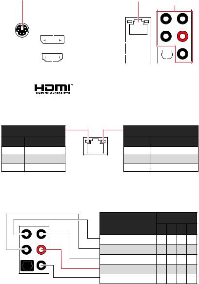
Rear I/O Panel
|
PS/2 Combo port |
2.5 Gbps LAN |
Audio Ports |
|
DisplayPort |
||
|
USB 2.0 |
|||||||||||||||||||||||||||
|
Type-A |
Gen 1 |
||||||||||||||||||||||||||
|
USB 3.2 |
|||||||||||||||||||||||||||
|
(5Gbps) Type-A |
|||||||||||||||||||||||||||
|
Optical |
|||||||||||||||||||||||||||
|
S/PDIF-Out |
LAN Port LED Status Table
Link/ Activity LED
|
Status |
Description |
|
Off |
No link |
|
Yellow |
Linked |
|
Blinking |
Data activity |
Speed LED
|
Status |
2.5 Gbps LAN |
|
Off |
10 Mbps |
|
Green |
100 Mbps/ 1 Gbps |
|
Orange |
2.5 Gbps |
Audio Ports Configuration
|
Audio Ports |
Channel |
||||
|
2 |
4 |
6 |
8 |
||
|
Center/ Subwoofer Out |
● |
● |
|||
|
Rear Speaker Out |
● |
● |
● |
||
|
Line-In/ Side Speaker Out |
● |
||||
|
Line-Out/ Front Speaker Out ● |
● |
● |
● |
||
|
Mic In |
|||||
|
(●: connected, Blank: empty) |
10 Rear I/O Panel
![]()
Realtek Audio Console
After Realtek Audio Console is installed. You can use it to change sound settings to get better sound experience.
Application Enhancement
Device
Selection
 Main Volume
|
Connector Settings |
||
|
Jack Status |
∙∙Device Selection — allows you to select a audio output source to change the related options. The check sign indicates the devices as default.
∙∙Application Enhancement — the array of options will provide you a complete guidance of anticipated sound effect for both output and input device.
∙∙Main Volume — controls the volume or balance the right/left side of the speakers that you plugged in front or rear panel by adjust the bar.
∙∙Jack Status — depicts all render and capture devices currently connected with your computer.
∙∙Connector Settings — configures the connection settings.
Auto popup dialog
When you plug into a device at an audio jack, a dialogue window will pop up asking you which device is current connected.
Each jack corresponds to its default setting as shown on the next page.
Important
The pictures above for reference only and may vary from the product you purchased.
Rear I/O Panel 11
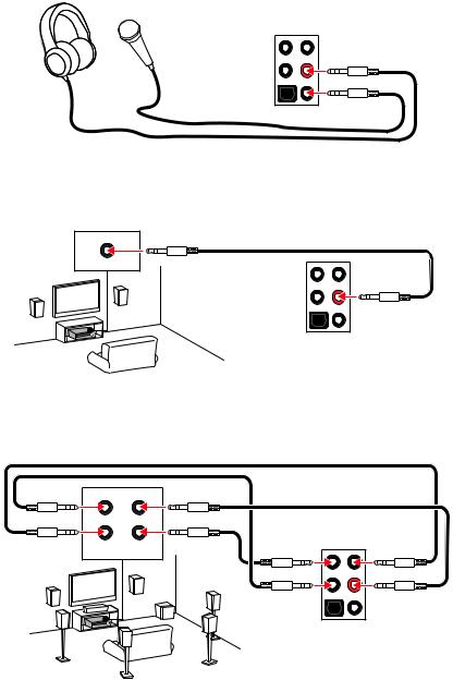
Audio jacks to headphone and microphone diagram
Audio jacks to stereo speakers diagram
AUDIO INPUT
Audio jacks to 7.1-channel speakers diagram
AUDIO INPUT
|
Rear |
Front |
|
Side |
Center/ |
|
Subwoofer |
12 Rear I/O Panel
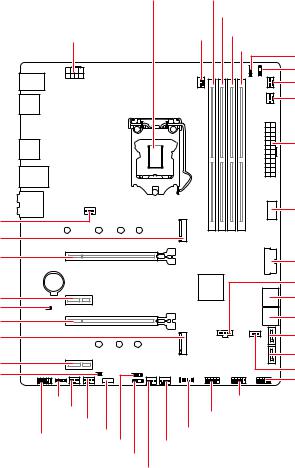
Overview of Components
|
CPU Socket |
DIMMA1 |
||||||
|
DIMMA2 |
|||||||
|
CPU_PWR1 |
CPU_FAN1 |
DIMMB1 |
|||||
|
DIMMB2 |
JRGB2 |
||||||
|
JRAINBOW2 |
|||||||
|
PUMP_FAN1 |
|||||||
|
SYS_FAN6 |
|||||||
|
ATX_PWR1 |
|||||||
|
SYS_FAN1 |
JUSB1 |
||||||
|
M2_1 |
|||||||
|
PCI_E1 |
JUSB2 |
||||||
|
BAT1 |
JTBT1 |
||||||
|
PCI_E2 |
SATA▼1▲2 |
||||||
|
JBAT1 |
SATA▼3▲4 |
||||||
|
PCI_E3 |
|||||||
|
M2_2 |
SATA5 |
||||||
|
PCI_E4 |
SATA6 |
||||||
|
JRTD3 |
|||||||
|
JCI1 |
|||||||
|
JRGB1 |
JUSB3 |
JFP1 |
|||||
|
SYS_FAN2 |
JUSB4 |
||||||
|
SYS_FAN3 |
JTPM1 |
||||||
|
JAUD1 |
LED_SW1 |
||||||
|
JFP2 |
SYS_FAN5 |
||||||
|
JRAINBOW1 |
|||||||
|
SYS_FAN4 |
Overview of Components 13
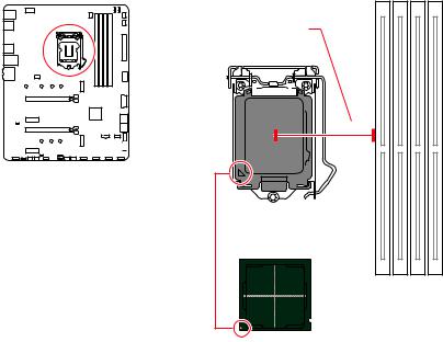
CPU Socket
Distance from the center of the
CPU to the nearest DIMM slot.
50.77 mm
Introduction to the LGA 1200 CPU
The surface of the LGA 1200 CPU has two notches and a golden triangle to assist in correctly lining up the CPU for motherboard placement. The golden triangle is the Pin 1 indicator.
Important
∙∙Always unplug the power cord from the power outlet before installing or removing the CPU.
∙∙Please retain the CPU protective cap after installing the processor. MSI will deal with Return Merchandise Authorization (RMA) requests if only the motherboard comes with the protective cap on the CPU socket.
∙∙When installing a CPU, always remember to install a CPU heatsink. A CPU heatsink is necessary to prevent overheating and maintain system stability.
∙∙Confirm that the CPU heatsink has formed a tight seal with the CPU before booting your system.
∙∙Overheating can seriously damage the CPU and motherboard. Always make sure the cooling fans work properly to protect the CPU from overheating. Be sure to apply an even layer of thermal paste (or thermal tape) between the CPU and the heatsink to enhance heat dissipation.
∙∙Whenever the CPU is not installed, always protect the CPU socket pins by covering the socket with the plastic cap.
∙∙If you purchased a separate CPU and heatsink/ cooler, Please refer to the documentation in the heatsink/ cooler package for more details about installation. ∙∙This motherboard is designed to support overclocking. Before attempting to overclock, please make sure that all other system components can tolerate overclocking. Any attempt to operate beyond product specifications is not recommended. MSI® does not guarantee the damages or risks caused by inadequate operation beyond product specifications.
14 Overview of Components
DIMM Slots
|
DIMMA1 |
DIMMB1 |
||||||||||||||||||||||||||||||||||||
|
Channel A |
Channel B |
||||||||||||||||||||||||||||||||||||
|
DIMMA2 |
DIMMB2 |
||||||||||||||||||||||||||||||||||||
Memory module installation recommendation
|
DIMMA1 |
|||
|
DIMMA2 |
DIMMA2 |
DIMMA2 |
|
|
DIMMB1 |
|||
|
∙∙ |
DIMMB2 |
DIMMB2 |
|
Important
Always insert memory modules in the DIMMA2 slot first.
∙∙To ensure system stability for Dual channel mode, memory modules must be of the same type, number and density.
∙∙Some memory modules may operate at a lower frequency than the marked value when overclocking due to the memory frequency operates dependent on its Serial Presence Detect (SPD). Go to BIOS and find the DRAM Frequency to set the memory frequency if you want to operate the memory at the marked or at a higher frequency. ∙∙It is recommended to use a more efficient memory cooling system for full DIMMs installation or overclocking.
∙∙The stability and compatibility of installed memory module depend on installed CPU and devices when overclocking.
∙∙Please refer www.msi.com for more information on compatible memory.
Overview of Components 15
PCI_E4: PCIe 3.0 x1 (PCH)
PCI_E1~4: PCIe Expansion Slots


 PCI_E1: PCIe 3.0 x16 (CPU)
PCI_E2: PCIe 3.0 x1 (PCH)

 PCI_E3: PCIe 3.0 x4 (PCH)
Important
∙∙PCI_E3 will be unavailable when installing M.2 SSD in the M2_2 slot.
∙∙If you install a large and heavy graphics card, you need to use a tool such as MSI Gaming Series Graphics Card Bolster to support its weight to prevent deformation of the slot.
∙∙For a single PCIe x16 expansion card installation with optimum performance, using the PCI_E1 slot is recommended.
∙∙When adding or removing expansion cards, always turn off the power supply and unplug the power supply power cable from the power outlet. Read the expansion card’s documentation to check for any necessary additional hardware or software changes.
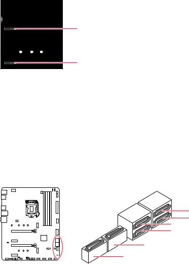
SATA1~6: SATA 6Gb/s Connectors
These connectors are SATA 6Gb/s interface ports. Each connector can connect to one SATA device.
SATA2
SATA4
SATA1
SATA3
SATA5
SATA6
Important
∙∙Please do not fold the SATA cable at a 90-degree angle.Data loss may result during transmission otherwise.
∙∙SATA cables have identical plugs on either sides of the cable. However, it is recommended that the flat connector be connected to the motherboard for space saving purposes.
∙∙SATA1 will be unavailable when installing M.2 SATA SSD in the M2_1 slot.
16 Overview of Components
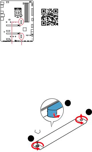
M2_1~2: M.2 Slots (Key M)
Video Demonstration
Watch the video to learn how to Install M.2 module. http://youtu.be/JCTFABytrYA
M2_1 M2_2
Important
∙∙Intel® RST only supports PCIe M.2 SSD with UEFI ROM (M2_2 slot only). ∙∙Intel® Optane™ Memory Ready for all M2_2 slot.
M2_1 slot installation
1. Loosen the screws of M.2 SHIELD FROZR heatsink.
2. Remove the M.2 SHIELD FROZR and remove the protective films from the thermal pads.
2
 1
1
1 
Overview of Components 17
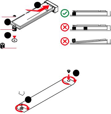
3.Move and fasten the M.2 standoff to the appropriate position for your M.2 SSD, or remove the M.2 standoff if your M.2 SSD length is same as the length of M.2 heatsink to avoid damage to the M.2 SSD.
4.Insert your M.2 SSD into the M.2 slot at a 30-degree angle.
5.Secure the M.2 SSD in place with the M.2 screw, or skip this step if you remove the M.2 standoff in step 3.
heatsink standoff
6. Put the M.2 SHIELD FROZR heatsink back in place and secure it.
6
 6
6
M2_2 slot installation
Please follows the step3, 4 and 5 to install the M.2 SSD to the M2_2 slot.
18 Overview of Components
JFP1
|
-+-+ |
||||||||
|
2 |
10 |
|||||||
|
1 |
9 |
Reserved |
||||||
|
+ +— |
 HDD LED

 Reset Switch
|
1 |
HDD LED + |
2 |
Power LED + |
|
3 |
HDD LED — |
4 |
Power LED — |
|
5 |
Reset Switch |
6 |
Power Switch |
|
7 |
Reset Switch |
8 |
Power Switch |
|
9 |
Reserved |
10 |
No Pin |
JFP2
|
Buzzer |
1 |
Speaker — |
2 |
Buzzer + |
|||||
|
Speaker |
|||||||||
|
3 |
Buzzer — |
4 |
Speaker + |
||||||
JAUD1: Front Audio Connector
This connector allows you to connect audio jacks on the front panel.
|
2 |
10 |
||
|
1 |
9 |
||
|
1 |
MIC L |
2 |
Ground |
|
3 |
MIC R |
4 |
NC |
|
5 |
Head Phone R |
6 |
MIC Detection |
|
7 |
SENSE_SEND |
8 |
No Pin |
|
9 |
Head Phone L |
10 |
Head Phone Detection |
Overview of Components 19
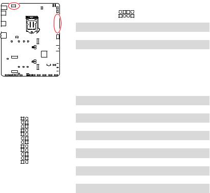
CPU_PWR1, ATX_PWR1: Power Connectors
These connectors allow you to connect an ATX power supply.
|
8 |
5 |
CPU_PWR1 |
||||||||||||||||||||||||||||||||||
|
4 |
1 |
|||||||||||||||||||||||||||||||||||
|
1 |
Ground |
5 |
+12V |
|||||||||||||||||||||||||||||||||
|
2 |
Ground |
6 |
+12V |
|||||||||||||||||||||||||||||||||
|
3 |
Ground |
7 |
+12V |
|||||||||||||||||||||||||||||||||
|
4 |
Ground |
8 |
+12V |
|||||||||||||||||||||||||||||||||
|
1 |
+3.3V |
13 |
+3.3V |
|||||
|
2 |
+3.3V |
14 |
-12V |
|||||
|
12 |
24 |
3 |
Ground |
15 |
Ground |
|||
|
4 |
+5V |
16 |
PS-ON# |
|||||
|
5 |
Ground |
17 |
Ground |
|||||
|
ATX_PWR1 |
6 |
+5V |
18 |
Ground |
||||
|
7 |
Ground |
19 |
Ground |
|||||
|
1 |
13 |
8 |
PWR OK |
20 |
Res |
|||
|
9 |
5VSB |
21 |
+5V |
|||||
|
10 |
+12V |
22 |
+5V |
|||||
|
11 |
+12V |
23 |
+5V |
|||||
|
12 |
+3.3V |
24 |
Ground |
|||||
|
Important |
||||||||
|
Make sure that all the power cables are securely connected to a proper ATX power |
||||||||
|
supply to ensure stable operation of the motherboard. |
20 Overview of Components
![]()
JUSB1: USB 3.2 Gen 1 5Gbps Type-C Connector
This connector allows you to connect USB 3.2 Gen 1 5Gbps Type-C connector on the front panel. The connector possesses a foolproof design. When you connect the cable, be sure to connect it with the corresponding orientation.
USB Type-C port on the front panel
JUSB2: USB 3.2 Gen 1 5Gbps Connector
This connector allows you to connect USB 3.2 Gen 1 5Gbps ports on the front panel.
|
10 |
11 |
||||
|
1 |
20 |
||||
|
1 |
Power |
11 |
USB2.0+ |
||
|
2 |
USB3_RX_DN |
12 |
USB2.0- |
||
|
3 |
USB3_RX_DP |
13 |
Ground |
||
|
4 |
Ground |
14 |
USB3_TX_C_DP |
||
|
5 |
USB3_TX_C_DN |
15 |
USB3_TX_C_DN |
||
|
6 |
USB3_TX_C_DP |
16 |
Ground |
||
|
7 |
Ground |
17 |
USB3_RX_DP |
||
|
8 |
USB2.0- |
18 |
USB3_RX_DN |
||
|
9 |
USB2.0+ |
19 |
Power |
||
|
10 |
Ground |
20 |
No Pin |
||
Important
Note that the Power and Ground pins must be connected correctly to avoid possible damage.
Overview of Components 21

JUSB3~4: USB 2.0 Connectors
These connectors allow you to connect USB 2.0 ports on the front panel.
|
2 |
10 |
|||
|
1 |
9 |
|||
|
1 |
VCC |
2 |
VCC |
|
|
3 |
USB0- |
4 |
USB1- |
|
|
5 |
USB0+ |
6 |
USB1+ |
|
|
7 |
Ground |
8 |
Ground |
|
|
∙∙ |
9 |
No Pin |
10 |
NC |
|
Important |
Note that the VCC and Ground pins must be connected correctly to avoid possible damage.
∙∙In order to recharge your iPad,iPhone and iPod through USB ports, please install MSI® DRAGON CENTER utility.
JTPM1: TPM Module Connector
This connector is for TPM (Trusted Platform Module). Please refer to the TPM security platform manual for more details and usages.
|
2 |
12 |
||
|
1 |
11 |
||
|
1 |
SPI Power |
2 |
SPI Chip Select |
|
3 |
Master In Slave Out (SPI Data) |
4 |
Master In Slave In (SPI Data) |
|
5 |
Reserved |
6 |
SPI Clock |
|
7 |
Ground |
8 |
SPI Reset |
|
9 |
Reserved |
10 |
No Pin |
|
11 |
Reserved |
12 |
Interrupt Request |
22 Overview of Components

There are gradient points of the fan speed that allow you to adjust fan speed in relation to CPU temperature.
CPU_FAN1, PUMP_FAN1, SYS_FAN1~6: Fan Connectors
Fan connectors can be classified as PWM (Pulse Width Modulation) Mode or DC Mode. PWM Mode fan connectors provide constant 12V output and adjust fan speed with speed control signal. DC Mode fan connectors control fan speed by changing voltage. You can follow the instruction below to adjust the fan connector to PWM or DC Mode manually.
SYS_FAN1 CPU_FAN1 PUMP_FAN1
|
Connector |
Default fan |
Max. |
Max. |
|||||||||||||||||||||||||
|
mode |
current |
power |
||||||||||||||||||||||||||
|
CPU_FAN1 |
PWM mode |
2A |
24W |
|||||||||||||||||||||||||
|
PUMP_FAN1 |
PWM mode |
3A |
36W |
|||||||||||||||||||||||||
|
SYS_FAN1~6 |
DC mode |
2A |
24W |
|||||||||||||||||||||||||
SYS_FAN2 SYS_FAN4 SYS_FAN6
SYS_FAN3 SYS_FAN5
Switching fan mode and adjusting fan speed
You can switch between PWM mode and DC mode and adjust fan speed in BIOS > HARDWARE MONITOR.
Select PWM mode or DC mode
Important
Make sure fans are working properly after switching the PWM/ DC mode.
Pin definition of fan connectors
|
1 |
PWM Mode pin definition |
||||
|
1 |
Ground |
2 |
+12V |
||
|
3 |
Sense |
4 |
Speed Control Signal |
|
1 |
DC Mode pin definition |
||||
|
1 |
Ground |
2 |
Voltage Control |
||
|
3 |
Sense |
4 |
NC |
Overview of Components 23

JCI1: Chassis Intrusion Connector
This connector allows you to connect the chassis intrusion switch cable.
|
Normal |
Trigger the chassis |
|
(default) |
intrusion event |
Using chassis intrusion detector
1. Connect the JCI1 connector to the chassis intrusion switch/ sensor on the chassis. 2. Close the chassis cover.
3. Go to BIOS > SETTINGS > Security > Chassis Intrusion Configuration. 4. Set Chassis Intrusion to Enabled.
5. Press F10 to save and exit and then press the Enter key to select Yes.
6. Once the chassis cover is opened again, a warning message will be displayed on screen when the computer is turned on.
Resetting the chassis intrusion warning
1. Go to BIOS > SETTINGS > Security > Chassis Intrusion Configuration. 2. Set Chassis Intrusion to Reset.
3. Press F10 to save and exit and then press the Enter key to select Yes.
24 Overview of Components

JBAT1: Clear CMOS (Reset BIOS) Jumper
There is CMOS memory onboard that is external powered from a battery located on the motherboard to save system configuration data. If you want to clear the system configuration, set the jumpers to clear the CMOS memory.
Keep Data
(default)
Resetting BIOS to default values
1. Power off the computer and unplug the power cord.
2. Use a jumper cap to short JBAT1 for about 5-10 seconds. 3. Remove the jumper cap from JBAT1.
4. Plug the power cord and Power on the computer.
JTBT1: Thunderbolt Add-on Card Connector
This connector allows you to connect the add-on Thunderbolt I/O card.
JRTD3: Intel RTD3 Connector
This connector allows you to connect the RTD3 connector on the add-on Thunderbolt
I/O card that supports RTD3.
|
1 |
JTBT1 |
|||||||||||||||||||||||||||||||||||
|
1 |
FORCE_PWR |
2 |
SCI_EVENT |
|||||||||||||||||||||||||||||||||
|
3 |
SLP_S3# |
4 |
SLP_S5# |
|||||||||||||||||||||||||||||||||
|
5 |
Ground |
|||||||||||||||||||||||||||||||||||
|
1 |
JRTD3 |
|||||||||||||||||||||||||||||||||||
|
1 |
WAKE |
2 |
PWR EN |
|||||||||||||||||||||||||||||||||
|
3 |
GND |
Overview of Components 25

EZ Debug LED
These LEDs indicate the debug status of the motherboard.
CPU — indicates CPU is not detected or fail.
DRAM — indicates DRAM is not detected or fail.

 VGA — indicates GPU is not detected or fail.
BOOT — indicates the booting device is not detected
or fail.
LED_SW1: EZ LED Control
This switch is used to switch on/ off all the LEDs of motherboard.
|
LED_OFF |
LED_ON |
||||||||||||||||||||||||||||||
|
(Default) |
|||||||||||||||||||||||||||||||
26 Overview of Components

JRGB1~2: RGB LED connector
The JRGB connectors allow you to connect the 5050 RGB LED strips 12V.
RGB LED Strip Connection
1


 GR
GR  B
B
RGB extension JRGB cable connector
RGB LED Fan Connection
JRGB connector
|
1 |
JRGB1 |
1 |
JRGB2 |
|
1 |
+12V |
2 |
G |
|
3 |
R |
4 |
B |
5050 RGB LED strips 12V
1


 GR
GR  B
B
1
RGB LED Fan
System Fan connector
Important
∙∙The JRGB connector supports up to 2 meters continuous 5050 RGB LED strips (12V/G/R/B) with the maximum power rating of 3A (12V).
∙∙Always turn off the power supply and unplug the power cord from the power outlet before installing or removing the RGB LED strip.
∙∙Please use MSI’s software to control the extended LED strip.
Overview of Components 27

Addressable RGB LED Fan
JRAINBOW1~2: Addressable RGB LED connectors
The JRAINBOW connectors allow you to connect the WS2812B Individually Addressable RGB LED strips 5V.
|
1 |
1 |
||
|
JRAINBOW1 |
|||
|
JRAINBOW2 |
|||
|
1 |
+5V |
2 |
Data |
|
3 |
No Pin |
4 |
Ground |
Addressable RGB LED Strip Connection
1 
+5V D
|
JRAINBOW |
|||||||||||
|
Rainbow |
RGB LED |
||||||||||
|
WS2812B Individually |
|||||||||||
|
connector |
extension cable |
||||||||||
|
Addressable RGB LED strips 5V |
Addressable RGB LED Fan Connection
JRAINBOW connector
1 
1
System Fan connector
CAUTION
Do not connect the wrong type of LED strips. The JRGB connector and the JRAINBOW connector provide different voltages, and connecting the 5V LED strip to the JRGB connector will result in damage to the LED strip.
Important
∙∙The JRAINBOW connector supports up to 75 LEDs WS2812B Individually Addressable RGB LED strips (5V/Data/Ground) with the maximum power rating of 3A (5V). In the case of 20% brightness, the connector supports up to 200 LEDs.
∙∙Always turn off the power supply and unplug the power cord from the power outlet before installing or removing the RGB LED strip.
∙∙Please use MSI’s software to control the extended LED strip.
28 Overview of Components
Installing OS, Drivers & Utilities
Please download and update the latest utilities and drivers at www.msi.com
Installing Windows® 10
1. Power on the computer.
2. Insert the Windows® 10 installation disc/USB into your computer. 3. Press the Restart button on the computer case.
4. Press F11 key during the computer POST (Power-On Self Test) to get into Boot
Menu.
5. Select the Windows® 10 installation disc/USB from the Boot Menu.
6. Press any key when screen shows Press any key to boot from CD or DVD…
message.
7. Follow the instructions on the screen to install Windows® 10.
Installing Drivers
1. Start up your computer in Windows® 10.
2. Insert MSI® Drive Disc into your optical drive.
3. Click the Select to choose what happens with this disc pop-up notification, then select Run DVDSetup.exe to open the installer. If you turn off the AutoPlay feature from the Windows Control Panel, you can still manually execute the DVDSetup.exe from the root path of the MSI Drive Disc.
4. The installer will find and list all necessary drivers in the Drivers/Software tab.
5. Click the Install button in the lower-right corner of the window.
6. The drivers installation will then be in progress, after it has finished it will prompt you to restart.
7. Click OK button to finish.
8. Restart your computer.
Installing Utilities
Before you install utilities, you must complete drivers installation. 1. Open the installer as described above.
2. Click the Utilities tab.
3. Select the utilities you want to install.
4. Click the Install button in the lower-right corner of the window.
5. The utilities installation will then be in progress, after it has finished it will prompt you to restart.
6. Click OK button to finish.
7. Restart your computer.
Installing OS, Drivers & Utilities 29

UEFI BIOS
MSI UEFI BIOS is compatible with UEFI (Unified Extensible Firmware Interface) architecture. UEFI has many new functions and advantages that traditional BIOS cannot achieve, and it will completely replace BIOS in the future. The MSI UEFI BIOS uses UEFI as the default boot mode to take full advantage of the new chipset’s capabilities. However, it still has a CSM (Compatibility Support Module) mode to be compatible with older devices. That allows you to replace legacy devices with UEFI compatible devices during the transition.
Important
The term BIOS in this user guide refers to UEFI BIOS unless otherwise noted.
UEFI advantages
∙∙Fast booting — UEFI can directly boot the operating system and save the BIOS selftest process. And also eliminates the time to switch to CSM mode during POST.
∙∙Supports for hard drive partitions larger than 2 TB.
∙∙Supports more than 4 primary partitions with a GUID Partition Table (GPT). ∙∙Supports unlimited number of partitions.
∙∙Supports full capabilities of new devices — new devices may not provide backward compatibility.
∙∙Supports secure startup — UEFI can check the validity of the operating system to ensure that no malware tampers with the startup process.
Incompatible UEFI cases
∙∙32-bit Windows operating system — this motherboard supports only Windows 10 64-bit operating system.
∙∙Older graphics card — the system will detect your graphics card. When display a warning message There is no GOP (Graphics Output protocol) support detected in this graphics card.
Important
We recommend that you to use a GOP/ UEFI compatible graphics card.
How to check the BIOS mode?
After entering the BIOS, find the BIOS Mode at the top of the screen.
CPU Temperature:
Motherboard Temperature:
VCore:
DDR Voltage:
BIOS Mode: UEFI/ CSM
UEFI boot mode
CPU Temperature:
Motherboard Temperature:
VCore:
DDR Voltage:
BIOS Mode: UEFI/ CSM
CSM boot mode
30 UEFI BIOS
BIOS Setup
The default settings offer the optimal performance for system stability in normal conditions. You should always keep the default settings to avoid possible system damage or failure booting unless you are familiar with BIOS.
Important
∙∙BIOS items are continuously update for better system performance. Therefore, the description may be slightly different from the latest BIOS and should be for reference only. You could also refer to the HELP information panel for BIOS item description.
∙∙The pictures in this chapter are for reference only and may vary from the product you purchased.
∙∙The BIOS items will vary with the processor.
Entering BIOS Setup
Press Delete key, when the Press DEL key to enter Setup Menu, F11 to enter Boot Menu message appears on the screen during the boot process.
Function key
F1: General Help list
F2: Add/ Remove a favorite item
F3: Enter Favorites menu
F4: Enter CPU Specifications menu
F5: Enter Memory-Z menu
F6: Load optimized defaults
F7: Switch between Advanced mode and EZ mode
F8: Load Overclocking Profile
F9: Save Overclocking Profile
F10: Save Change and Reset*
F12: Take a screenshot and save it to USB flash drive (FAT/ FAT32 format only). Ctrl+F: Enter Search page
* When you press F10, a confirmation window appears and it provides the modification information. Select between Yes or No to confirm your choice.
UEFI BIOS 31

Resetting BIOS
You might need to restore the default BIOS setting to solve certain problems. There are several ways to reset BIOS:
∙∙Go to BIOS and press F6 to load optimized defaults. ∙∙Short the Clear CMOS jumper on the motherboard.
Important
Be sure the computer is off before clearing CMOS data. Please refer to the Clear CMOS jumper section for resetting BIOS.
Updating BIOS
Updating BIOS with M-FLASH
Before updating:
Please download the latest BIOS file that matches your motherboard model from MSI website. And then save the BIOS file into the USB flash drive.
Updating BIOS:
1. Insert the USB flash drive that contains the update file into the USB port. 2. Please refer the following methods to enter flash mode.
▪▪Reboot and press Ctrl + F5 key during POST and click on Yes to reboot the system.
Press <Ctrl+F5> to activate M-Flash for BIOS update.
▪▪Reboot and press Del key during POST to enter BIOS. Click the M-FLASH button and click on Yes to reboot the system.
3.Select a BIOS file to perform the BIOS update process.
4.When prompted click on Yes to start recovering BIOS.
5.After the flashing process is 100% completed, the system will reboot automatically.
32 UEFI BIOS

Updating the BIOS with MSI DRAGON CENTER
Before updating:
Make sure the LAN driver is already installed and the internet connection is set properly.
Updating BIOS:
1. Install and launch MSI DRAGON CENTER and go to Support page. 2. Select Live Update and click on Advance button.
3. Click on Scan button to search the latest BIOS file.
4. Select the BIOS file and click on Download icon to download and install the latest BIOS file.
5. Click Next and choose In Windows mode. And then click Next and Start to start updating BIOS.
6. After the flashing process is 100% completed, the system will restart automatically.
UEFI BIOS 33

EZ Mode
At EZ mode, it provides the basic system information and allows you to configure the basic setting. To configure the advanced BIOS settings, please enter the Advanced Mode by pressing the Setup Mode switch or F7 function key.
|
XMP Profile |
Setup Mode switch |
Screenshot |
Search |
Language |
|||||||||||||||||||||||||||||||
|
System |
|||||||||||||||||||||||||||||||||||
|
information |
|||||||||||||||||||||||||||||||||||
|
GAME |
BOOST |
||||||||||||||||||||||||||||||||||
|
Boot |
device |
||||||||||||||||||||||||||||||||||
|
priority bar |
|||||||||||||||||||||||||||||||||||
|
Component |
|||||||||||||||||||||||||||||||||||
|
Information |
|||||||||||||||||||||||||||||||||||
|
M-Flash |
|||||||||||||||||||||||||||||||||||
|
Favorites |
|||||||||||||||||||||||||||||||||||
|
Function |
|||||||||||||||||||||||||||||||||||
|
Hardware |
buttons |
||||||||||||||||||||||||||||||||||
|
Monitor |
|||||||||||||||||||||||||||||||||||
∙∙GAME BOOST — click on it to toggle the GAME BOOST for overclocking. This function is only available when both of the motherboard and CPU are supporting this function.
Important
Please don’t make any changes in OC menu and don’t load defaults to keep the optimal performance and system stability after activating the GAME BOOST function.
∙∙XMP Profile — allows you to select the XMP profile for memory to overclock. This function is only available when the system, memory and CPU are supporting this function.
∙∙Setup Mode switch — press this tab or the F7 key to switch between Advanced mode and EZ mode.
∙∙Screenshot — click on this tab or the F12 key to take a screenshot and save it to USB flash drive (FAT/ FAT32 format only).
∙∙Search — click on this tab or the Ctrl+F keys to enter the search page. It allows you to search by BIOS item name. Move the mouse over a blank space and right click the mouse to exit the search page.
Important
In search page, only the F6, F10 and F12 function keys are available.
34 UEFI BIOS

∙∙Language — allows you to select language of BIOS setup.
∙∙System information — shows the CPU/ DDR speed, CPU/ MB temperature, MB/ CPU type, memory size, CPU/ DDR voltage, BIOS version and build date.
∙∙Boot device priority bar — you can move the device icons to change the boot priority.
The boot priority from high to low is left to right.
∙∙Component Information — click on the CPU, Memory, Storage, Fan Info and Help buttons to show the information of connected component.
∙∙Function buttons — enable or disable these functions by clicking on these buttons.
The function is enabled when the button shows ON .
Important
The function buttons will vary with the motherboard you purchased.
∙∙M-Flash — click on this button to enter the M-Flash menu that provides the way to update BIOS with a USB flash drive.
∙∙Hardware Monitor — click on this button to enter the Hardware Monitor menu that allows you to manually control the fan speed by percentage.
∙∙Favorites — click on this button or press the F3 key to show the Favorites window. It provides 5 menus for you to create personal BIOS menu where you can save and access favorite/ frequently-used BIOS setting items.
UEFI BIOS 35

▪▪To add a BIOS item to a favorite menu
1. Select a BIOS item not only on BIOS menu but also on search page.
2. Right-click or press F2 key.
3. Choose a favorite page and click on OK.
▪▪To delete a BIOS item from favorite menu 1. Select a BIOS item on favorite menu.
2. Right-click or press F2 key.
3. Choose Delete and click on OK.
36 UEFI BIOS

Advanced Mode
Press Setup Mode switch or F7 function key can switch between EZ Mode and Advanced Mode in BIOS setup.
|
BIOS |
menu |
|||||||
|
BIOS menu |
||||||||
|
selection |
selection |
|||||||
Menu display
∙∙BIOS menu selection — the following options are available:
▪▪SETTINGS — allows you to specify the parameters for chipset and boot devices. ▪▪OC — allows you to adjust the frequency and voltage. Increasing the frequency may get better performance.
▪▪M-FLASH — provides the way to update BIOS with a USB flash drive. ▪▪OC PROFILE — allows you to manage overclocking profiles. ▪▪HARDWARE MONITOR — allows you to set the speeds of fans and monitor voltages of system.
▪▪BOARD EXPLORER — provides the information of installed devices on this
motherboard.
∙∙Menu display — provides BIOS setting items and information to be configured.
UEFI BIOS 37
OC Menu
This menu allows you to configure the frequencies and voltages for overclocking. Please note that, higher frequency and voltage may benefit overclocking capability but cause system un-stability.
Important
∙∙Overclocking your PC manually is only recommended for advanced users.
∙∙Overclocking is not guaranteed, and if done improperly, it could void your warranty or severely damage your hardware.
∙∙If you are unfamiliar with overclocking, we advise you to use GAME BOOST function for easy overclocking.
∙∙The BIOS items in OC menu will vary with the processor.
|
OC Explore Mode [Normal] |
|
|
Enables or disables to show the normal or expert version of OC settings. |
|
|
[Normal] |
Provides the regular OC settings in BIOS setup. |
|
[Expert] |
Provides the advanced OC settings for OC expert to configure in BIOS |
setup.
Note: We use * as the symbol for the OC settings of Expert mode.
CPU Ratio Apply Mode [All Core]*
Sets applied mode for CPU ratio. This item only appears when a CPU that supports Turbo Boost is installed.
CPU Ratio [Auto]
Sets the CPU ratio that is used to determine CPU clock speed. This item only appears when CPU Ratio Apply Mode set to All Core.
Adjusted CPU Frequency
Shows the adjusted CPU frequency. Read-only.
Advanced CPU Configuration
Press Enter to enter the sub-menu. User can set the parameters about CPU power/ current. The system may become unstable or unbootable after changing the parameters. If it occurs, please clear the CMOS data and restore the default settings.
CPU Ratio Offset When Running AVX [Auto]
Sets a offset value to lower the CPU core ratio. It could be helpful for heat dissipation when running AVX instructions. When set to Auto, BIOS will configure this setting automatically. This item appears when the installed CPU supports this function.
Ring Ratio [Auto]
Sets the ring ratio. The valid value range depends on the installed CPU.
Adjusted Ring Frequency
Shows the adjusted Ring frequency. Read-only.
38 UEFI BIOS
GT Ratio [Auto]
Sets the integrated graphics ratio. The valid value range depends on the installed CPU.
Adjusted GT Frequency
Shows the adjusted integrated graphics frequency. Read-only.
Extreme Memory Profile (XMP) [Disabled]
XMP (Extreme Memory Profile) is the overclocking technology by memory module. Please enable XMP or select a profile of memory module for overclocking the memory. This item will be available when the memory modules that support XMP is installed.
Memory Try It ! [Disabled]
It can improve memory compatibility or performance by choosing optimized memory preset.
|
DRAM Timing Mode [Link] |
|
|
Selects the memory timing mode. |
|
|
[Link] |
Allows user to configure the DRAM timing for all memory channel. |
|
[UnLink] |
Allows user to configure the DRAM timing for respective memory |
|
channel. |
Advanced DRAM Configuration
Press Enter to enter the sub-menu. User can set the memory timing for each/ all memory channel. The system may become unstable or unbootable after changing memory timing. If it occurs, please clear the CMOS data and restore the default settings. (Refer to the Clear CMOS jumper/ button section to clear the CMOS data, and enter the BIOS to load the default settings.)
|
Memory Fast Boot [Auto] * |
|
|
Enables or disables the initiation and training for memory every booting. |
|
|
[Auto] |
The setting will be configured automatically by BIOS. |
|
[Enabled] |
System will completely keep the archives of first intiation and training |
|
for memory. And then the memory will not be initialed and trained when |
|
|
[Disabled] |
booting to accelerate the system booting time. |
|
The memory will be initialed and trained every booting. |
|
|
[Training] |
The memory will be trained every booting. |
DigitALL Power sub-menu
Press Enter to enter the sub-menu. In the sub-menu, you can setup some protecting conditions about voltage/ current/ temputure for CPU.
CPU Core Voltage Monitor [VCC Sense]
Selects the monitor source of CPU Core voltage.
CPU Voltages control [Auto]
These options allow you to set the voltages related to CPU. If set to Auto, BIOS will set these voltages automatically or you can set it manually.
UEFI BIOS 39
DRAM Voltages control [Auto]
These options allow you to set the voltages related to memory. If set to Auto, BIOS will set these voltages automatically or you can set it manually.
|
CPU Memory Changed Detect [Enabled]* |
|
|
Enables or disables the system to issue a warning message during boot when the CPU |
|
|
or memory has been replaced. |
|
|
[Enabled] |
The system will issue a warning message during boot and then you have |
|
[Disabled] |
to load the default settings for new devices. |
|
Disables this function and keeps the current BIOS settings. |
CPU Specifications sub-menu
Press Enter to enter the sub-menu. This sub-menu displays the information of installed CPU. You can also access this information menu at any time by pressing [F4]. Read only.
MEMORY-Z sub-menu
Press Enter to enter the sub-menu. This sub-menu displays all the settings and timings of installed memory. You can also access this information menu at any time by pressing [F5].
CPU Features sub-menu
Press Enter to enter the sub-menu. You can enable or disable the CPU features and technologies to protect CPU and improve the system performance.
40 UEFI BIOS
 Loading…
3.0
Rated 3 out of 5
3 out of 5 stars (based on 1 review)
Your overall rating
MSI MAG B460 TORPEDO (01) PDF MANUAL
Click here to download MSI MAG B460 TORPEDO (01) PDF MANUAL
MSI MAG B460 TORPEDO (01) PDF MANUAL
FREE ENGLISH PDF
OPERATING INSTRUCTIONS
USER GUIDE – USER MANUAL
OWNER GUIDE – OWNER MANUAL
REFERENCE GUIDE – REFERENCE MANUAL
INSTRUCTION GUIDE – INSTRUCTION MANUAL
Your overall rating
- YouTube
MSI MAG B460 TORPEDO (01) PDF MANUAL
MSI MAG B460 TORPEDO (01) PDF MANUAL
Посмотреть инструкция для MSI MAG B460 Torpedo бесплатно. Руководство относится к категории материнские платы, 1 человек(а) дали ему среднюю оценку 7.5. Руководство доступно на следующих языках: русский, английский. У вас есть вопрос о MSI MAG B460 Torpedo или вам нужна помощь? Задайте свой вопрос здесь
Не можете найти ответ на свой вопрос в руководстве? Вы можете найти ответ на свой вопрос ниже, в разделе часто задаваемых вопросов о MSI MAG B460 Torpedo.
Какая ширина MSI MAG B460 Torpedo?
MSI MAG B460 Torpedo имеет ширину 305 mm.
Какая толщина MSI MAG B460 Torpedo?
MSI MAG B460 Torpedo имеет толщину 244 mm.
Инструкция MSI MAG B460 Torpedo доступно в русский?
Да, руководствоMSI MAG B460 Torpedo доступно врусский .
Не нашли свой вопрос? Задайте свой вопрос здесь
∙ The components included in this package are prone to damage from electrostatic
discharge (ESD). Please adhere to the following instructions to ensure successful
computer assembly.
∙ Ensure that all components are securely connected. Loose connections may cause
the computer to not recognize a component or fail to start.
∙ Hold the motherboard by the edges to avoid touching sensitive components.
∙ It is recommended to wear an electrostatic discharge (ESD) wrist strap when
handling the motherboard to prevent electrostatic damage. If an ESD wrist strap is
not available, discharge yourself of static electricity by touching another metal object
before handling the motherboard.
∙ Store the motherboard in an electrostatic shielding container or on an anti-static
pad whenever the motherboard is not installed.
∙ Before turning on the computer, ensure that there are no loose screws or metal
components on the motherboard or anywhere within the computer case.
∙ Do not boot the computer before installation is completed. This could cause
permanent damage to the components as well as injury to the user.
∙ If you need help during any installation step, please consult a certified computer
technician.
∙ Always turn off the power supply and unplug the power cord from the power outlet
before installing or removing any computer component.
∙ Keep this user guide for future reference.
∙ Keep this motherboard away from humidity.
∙ Make sure that your electrical outlet provides the same voltage as is indicated on
the PSU, before connecting the PSU to the electrical outlet.
∙ Place the power cord such a way that people can not step on it. Do not place
anything over the power cord.
∙ All cautions and warnings on the motherboard should be noted.
∙ If any of the following situations arises, get the motherboard checked by service
personnel:
▪ Liquid has penetrated into the computer.
▪ The motherboard has been exposed to moisture.
▪ The motherboard does not work well or you can not get it work according to user
guide.
▪ The motherboard has been dropped and damaged.
▪ The motherboard has obvious sign of breakage.
∙ Do not leave this motherboard in an environment above 60°C (140°F), it may damage
the motherboard.
2
Quick Start