-
Contents
-
Table of Contents
-
Troubleshooting
-
Bookmarks
Quick Links
Questo manuale d’istruzione è fornito da trovaprezzi.it. Scopri tutte le offerte per
Gaming Edge WIFI
Thank you for purchasing the MSI®
GAMING PLUS
motherboard. This Quick Start section provides demonstration
diagrams about how to install your computer. Some of the installations also provide
video demonstrations. Please link to the URL to watch it with the web browser on your
phone or tablet. You may have even link to the URL by scanning the QR code.
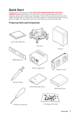
Preparing Tools and Components
Intel® LGA 1200 CPU
DDR4 Memory
Thermal Paste
Phillips Screwdriver
o cerca il tuo prodotto tra le
MPG Z590 GAMING EDGE WIFI/ MPG Z590
CPU Fan
Power Supply Unit
SATA Hard Disk Drive
A Package of Screws
migliori offerte di Schede Madri
Chassis
Graphics Card
SATA DVD Drive
MSI MPG Z590
1
Quick Start
Summary of Contents for MSI MPG Z590 GAMING PLUS
User Manual for MSI models including: MPG Z590 GAMING EDGE WIFI, MPG Z590 GAMING PLUS
Intel Optane™ Memory Configuration — Quick Start
Please adhere to the following instructions to ensure successful computer … Do not boot the computer before installation is completed. … 제조년월: 2021년.
UEFI BIOS — Quick Start
User manual. 1. Quick installation guide. 1. Application. USB drive with drivers & utilities. 1. Cable. SATA 6G cables (2 cables/pack). 1. LED JRGB Y cable.
Quick Start — Raru.co.za
Thank you for purchasing the MSI MPG Z590 GAMING EDGE WIFI/ MPG Z590 … RESET SW. Connecting the Front Panel Header http://youtu.be/DPELIdVNZUI.
- PDF Viewer
- Universal Document Viewer
- Google Docs View
- Google Drive View
- Download Document [pdf]
- Download Document [Optimized]
- Document:
- Text
- References
Not Your Device? Search For Manuals / Datasheets:
File Info : application/pdf, 58 Pages, 4.87MB
Document8571201-5438-user-manual
Quick Start
Thank you for purchasing the MSI® MPG Z590 GAMING EDGE WIFI/ MPG Z590 GAMING PLUS motherboard. This Quick Start section provides demonstration diagrams about how to install your computer. Some of the installations also provide video demonstrations. Please link to the URL to watch it with the web browser on your phone or tablet. You may have even link to the URL by scanning the QR code.
Preparing Tools and Components
Intel® LGA 1200 CPU
CPU Fan
DDR4 Memory
Power Supply Unit
Chassis Graphics Card
Thermal Paste
SATA Hard Disk Drive
SATA DVD Drive
Phillips Screwdriver
A Package of Screws
Quick Start 1
Safety Information
The components included in this package are prone to damage from electrostatic discharge (ESD). Please adhere to the following instructions to ensure successful computer assembly. Ensure that all components are securely connected. Loose connections may cause the computer to not recognize a component or fail to start. Hold the motherboard by the edges to avoid touching sensitive components. It is recommended to wear an electrostatic discharge (ESD) wrist strap when handling the motherboard to prevent electrostatic damage. If an ESD wrist strap is not available, discharge yourself of static electricity by touching another metal object before handling the motherboard. Store the motherboard in an electrostatic shielding container or on an anti-static pad whenever the motherboard is not installed. Before turning on the computer, ensure that there are no loose screws or metal components on the motherboard or anywhere within the computer case. Do not boot the computer before installation is completed. This could cause permanent damage to the components as well as injury to the user. If you need help during any installation step, please consult a certified computer technician. Always turn off the power supply and unplug the power cord from the power outlet before installing or removing any computer component. Keep this user guide for future reference. Keep this motherboard away from humidity. Make sure that your electrical outlet provides the same voltage as is indicated on the PSU, before connecting the PSU to the electrical outlet. Place the power cord such a way that people can not step on it. Do not place anything over the power cord. All cautions and warnings on the motherboard should be noted. If any of the following situations arises, get the motherboard checked by service personnel:
Liquid has penetrated into the computer. The motherboard has been exposed to moisture. The motherboard does not work well or you can not get it work according to user guide. The motherboard has been dropped and damaged. The motherboard has obvious sign of breakage. Do not leave this motherboard in an environment above 60°C (140°F), it may damage the motherboard.
2 Quick Start
Case stand-off notification
Before installing the motherboard into the case, install first the necessary mounting stand-off required for a motherboard on the mounting plate in the case. To prevent damage to the motherboard, any unnecessary mounting stand-off between the motherboard circuits and the computer case is prohibited. The Case standoff keep out zone signs will be marked on the backside of motherboard (as shown below) to serve as a warning to user.
Quick Start 3
Installing a Processor
2 1
3
7
4
5
9
6
8
4 Quick Start
Installing DDR4 memory
DIMMA2
DIMMA2 DIMMB2
DIMMA1 DIMMA2 DIMMB1 DIMMB2
Quick Start 5
Connecting the Front Panel Header
POPWOEWRELREHLDD-EDDL+ED
RESET SW POWER SW
Power LED Power Switch
-
-+
--
++
JFP1
2 1
+
10 9
Reserved
HDD LED Reset Switch
1
HDD LED +
2
3
HDD LED -
4
5
Reset Switch
6
7
Reset Switch
8
9
Reserved
10
Power LED + Power LED Power Switch Power Switch
No Pin
6 Quick Start
HDD LED POWER LED
HDD LED RESET SW
JFP1
HDD LED HDD LED + POWER LED POWER LED +
Installing the Motherboard
1
Torque:
3 kgf·cm*
2
*3 kgf·cm = 0.3 N·m = 2.6 lbf·in
Quick Start 7
Connecting the Power Connectors
ATX_PWR1
CPU_PWR1
8 Quick Start
CPU_PWR2
PCIE_PWR1
Installing SATA Drives
2
1 3
5 4
Quick Start 9
Installing a Graphics Card
1
3
2
5 10 Quick Start
4 6
Connecting Peripheral Devices
(MPG Z590 GAMING EDGE WIFI)
Quick Start 11
Power On
1
2
3 4
12 Quick Start
Contents
Quick Start ............................................................................................................. 1 Preparing Tools and Components.......................................................................... 1 Safety Information .................................................................................................. 2 Case stand-off notification ..................................................................................... 3 Installing a Processor ............................................................................................ 4 Installing DDR4 memory ........................................................................................ 5 Connecting the Front Panel Header ...................................................................... 6 Installing the Motherboard..................................................................................... 7 Connecting the Power Connectors ........................................................................ 8 Installing SATA Drives ............................................................................................ 9 Installing a Graphics Card.................................................................................... 10 Connecting Peripheral Devices............................................................................ 11 Power On .............................................................................................................. 12
Specifications....................................................................................................... 15
Package contents ................................................................................................ 22
Block Diagram .................................................................................................... 23
Rear I/O Panel ..................................................................................................... 24 LAN Port LED Status Table .................................................................................. 24 Audio Ports Configuration .................................................................................... 24 Realtek Audio Console ......................................................................................... 25 Installing Antennas (For MPG Z590 GAMING EDGE WIFI only) ........................... 27
Overview of Components .................................................................................... 28 CPU Socket ........................................................................................................... 30 DIMM Slots............................................................................................................ 31 PCI_E1~5: PCIe Expansion Slots.......................................................................... 32 JTBT1: Thunderbolt Add-on Card Connector ...................................................... 32 M2_1~3: M.2 Slots (Key M) ................................................................................... 33 SATA1~6: SATA 6Gb/s Connectors....................................................................... 35 JFP1, JFP2: Front Panel Connectors................................................................... 36 JAUD1: Front Audio Connector ............................................................................ 36 CPU_PWR1~2, ATX_PWR1, PCIE_PWR1: Power Connectors ............................. 37 JUSB4: USB 3.2 Gen 2 Type-C Connector............................................................ 38 JUSB3: USB 3.2 Gen 1 Connector ........................................................................ 38 JUSB1~2: USB 2.0 Connectors............................................................................. 39 JTPM1: TPM Module Connector........................................................................... 39 CPU_FAN1, PUMP_FAN1, SYS_FAN1~6: Fan Connectors.................................. 40 JCI1: Chassis Intrusion Connector....................................................................... 41
Contents 13
JBAT1: Clear CMOS (Reset BIOS) Jumper........................................................... 42 JRGB1~2: RGB LED connector............................................................................. 43 JRAINBOW1~2: Addressable RGB LED connectors ............................................ 44 Onboard LEDs...................................................................................................... 45 EZ Debug LED....................................................................................................... 45 LED_SW1: EZ LED Control ................................................................................... 45 JPWRLED1: LED power input............................................................................... 45 Installing OS, Drivers & MSI Center.................................................................... 46 Installing Windows® 10......................................................................................... 46 Installing Drivers .................................................................................................. 46 MSI Center ............................................................................................................ 46 UEFI BIOS............................................................................................................. 47 BIOS Setup............................................................................................................ 48 Entering BIOS Setup............................................................................................. 48 BIOS User Guide ................................................................................................... 48 Resetting BIOS...................................................................................................... 49 Updating BIOS....................................................................................................... 49 RAID Configuration.............................................................................................. 51 Intel® OptaneTM Memory Configuration .............................................................. 52 Troubleshooting ................................................................................................. 53
14 Contents
Specifications
CPU Chipset Memory
Expansion Slot Multi-GPU
Supports 10th Gen Intel® CoreTM Processors, 11th Gen Intel® CoreTM Processors, Pentium® Gold and Celeron® Processors* Processor socket LGA1200
* Please go to intel.com for compatibility information
Intel® Z590 Chipset
4x DDR4 memory slots, support up to 128GB* Supports 1R 2133/ 2666/ 2933 MHz for 10th Gen Intel® CPU (by JEDEC & POR)* Supports 1R 2133/ 2666/ 2933/ 3200 MHz for 11th Gen Intel® CPU (by JEDEC & POR)* Max overclocking frequency:
1DPC 1R Max speed up to 5333 MHz 1DPC 2R Max speed up to 4700+ MHz 2DPC 1R Max speed up to 4400+ MHz 2DPC 2R Max speed up to 4000+ MHz Supports Dual-Channel mode Supports non-ECC mode, un-buffered memory Supports Intel® Extreme Memory Profile (XMP)
* Please refer www.msi.com for more information on compatible memory.
3x PCIe x16 slots Support x16/ x4/ x4 PCI_E1 (From CPU) Supports up to PCIe 4.0 for 11th Gen Intel® CPU Supports up to PCIe 3.0 for 10th Gen Intel® CPU PCI_E3* & PCI_E5 (From Z590 chipset) Support up to PCIe 3.0
2x PCIe 3.0 x1 slots (From Z590 chipset)
* PCI_E3 will be unavailable when installing M.2 SSD in the M2_2 slot.
Supports AMD® CrossFireTM Technology
Continued on next page
Specifications 15
Onboard Graphics
Storage RAID Audio
Continued from previous page
1x HDMI 2.0b with HDR port, supports a maximum resolution of 4K 60Hz*/** 1x DisplayPort 1.4 port, supports a maximum resolution of 4K 60Hz*/**
* Available only on processors featuring integrated graphics. ** Graphics specifications may vary depending on the CPU installed.
6x SATA 6Gb/s ports (from Z590 chipset) 3x M.2 slots (Key M)
M2_1 slot (from CPU) Available only on 11th Gen Intel® CPU Supports up to PCIe 4.0 x4 Supports 2242/ 2260/ 2280/ 22110 storage devices
M2_2* & M2_3** slots (from Z590 chipset) Support up to PCIe 3.0 x4 and SATA 6Gb/s Supports 2242/ 2260/ 2280 storage devices Intel® OptaneTM Memory Ready***
Supports Intel® Smart Response Technology for Intel CoreTM processors
* PCI_E3 will be unavailable when installing M.2 SSD in the M2_2 slot. SATA2 will be unavailable when installing M.2 SATA SSD in the M2_2 slot. ** SATA5 & SATA6 will be unavailable when installing M.2 SSD in the M2_3 slot. *** Before using Intel® OptaneTM memory modules, please ensure that you have updated the drivers and BIOS to the latest version from MSI website.
Supports RAID 0, RAID 1, RAID 5 and RAID 10 for SATA storage devices Supports RAID 0, RAID 1 and RAID 5 for M.2 PCIe storage devices
Realtek® ALC4080 7.1-Channel High Definition Audio Supports S/PDIF output
Continued on next page
16 Specifications
Continued from previous page
Intel® Z590 Chipset
1x USB 3.2 Gen 2x2 20Gbps Type-C port on the back panel
4x USB 3.2 Gen 1 5Gbps ports (2 Type-A port on the
back panel and 2 ports are available through the internal
USB
connectors)
4x USB 3.2 Gen 2 10Gbps ports (1 Type-C internal connector and 3 Type-A ports on the back panel)
Hub-GL850G
6x USB 2.0 ports (2 Type-A port on the back panel and 4 ports are available through the internal connectors)
LAN
1x Intel® I225-V 2.5Gbps LAN controller
Wireless LAN & Bluetooth® (For MPG Z590 GAMING EDGE WIFI only)
Intel® WiFi 6E AX210 The Wireless module is pre-installed in the M.2 (Key-E) slot Supports MU-MIMO TX/RX, 2.4GHz/ 5GHz/ 6GHz* (160MHz) up to 2.4Gbps Supports 802.11 a/ b/ g/ n/ ac/ ax Supports Bluetooth® 5.2**, FIPS, FISMA
* Wi-Fi 6E 6GHz may depend on every country's regulations and will be ready in WIN10 21H1. ** Bluetooth 5.2 will be ready in WIN10 21H1.
Back Panel Connectors
1x Flash BIOS button 2x USB 2.0 ports 1x DisplayPort 1x HDMI port 2x USB 3.2 Gen 1 5Gbps Type-A ports 3x USB 3.2 Gen 2 10Gbps Type-A ports 1x USB 3.2 Gen 2x2 20Gbps 1x LAN (RJ45) port 2x Wi-Fi Antenna connectors (For MPG Z590 GAMING EDGE WIFI only) 5x audio jacks 1x Optical S/PDIF Out connector
Continued on next page
Specifications 17
Continued from previous page
Internal Connectors LED Features
1x 24-pin ATX main power connector 2x 8-pin ATX 12V power connectors 1x 6-pin ATX PCIE power connector 6x SATA 6Gb/s connectors 3x M.2 slots (M-Key) 1x USB 3.2 Gen 2 10Gbps Type-C port 1x USB 3.2 Gen 1 5Gbps connector (supports additional 2 USB 3.2 Gen 1 5Gbps ports) 2x USB 2.0 connectors (supports additional 4 USB 2.0 ports) 1x 4-pin CPU fan connector 1x 4-pin water-pump fan connector 6x 4-pin system fan connectors 1x Front panel audio connector 2x System panel connectors 1x Chassis Intrusion connector 1xTPM module connector 1x Clear CMOS jumper 1x TBT connector (Supports RTD3) 2x 4-pin RGB LED connectors 2x 3-pin RAINBOW LED connectors 1x EZ LED Control switch 4x EZ Debug LED
I/O Controller
NUVOTON NCT6687D Controller Chip
Hardware Monitor
CPU/ System/ Chipset temperature detection CPU/ System/ Pump fan speed detection CPU/ System/ Pump fan speed control
Form Factor
ATX Form Factor 12 in. x 9.6 in. (30.5 cm x 24.4 cm)
Continued on next page
18 Specifications
BIOS Features Software
MSI Center Features
Continued from previous page
1x 256 Mb flash UEFI AMI BIOS ACPI 6.2, SMBIOS 3.0 Multi-language
Drivers MSI Center Intel® Extreme Tuning Utility MSI APP Player (BlueStacks) Open Broadcaster Software (OBS) CPU-Z MSI GAMING Google ChromeTM, Google Toolbar, Google Drive NortonTM Internet Security Solution
MSI Sound Tune Gaming Mode Creator Mode Gaming Highlight LAN Manager Mystic Light Ambient Link (For MPG Z590 GAMING EDGE WIFI only) Frozr AI Cooling User Scenario True Color Live Update Monitor Super Charger Speed Up
Continued on next page
Specifications 19
Special Features
Continued from previous page
Audio Audio Boost 4 Sound Tune
Network 2.5G LAN LAN Manager Intel® WiFi (For MPG Z590 GAMING EDGE WIFI only)
Cooling M.2 Shield Frozr K7 thermal pad Choke pad Pump Fan Smart Fan Control
LED Mystic Light Mystic Light Extension (RAINBOW/RGB) Mystic Light SYNC Ambient Link EZ LED Control EZ DEBUG LED
Continued on next page
20 Specifications
Special Features
Continued from previous page
Performance Lightning Gen 4 PCI-E Slot Lightning Gen 4 M.2 Multi GPU CrossFire Technology DDR4 Boost Core Boost Game Boost Lightning USB 20g USB 3.2 Gen 2 10G USB with Type A+C Front USB Type-C Dual CPU Power Server PCB 2oz Copper thickened PCB
Protection PCI-E Steel Armor Pre-installed I/O Shielding
Experience MSI Center Frozr AI Cooling Click BIOS 5 Flash BIOS Button
Specifications 21
Package contents
Please check the contents of your motherboard package. It should contain:
Motherboard Documentation Application Cable
Accessories
Gift
MPG Z590 GAMING EDGE WIFI / MPG Z590 GAMING PLUS
User manual
1
Quick installation guide
1
USB drive with drivers & utilities
1
SATA 6G cables (2 cables/pack)
1
LED JRGB Y cable
1
LED JRAINBOW cable
1
Wi-Fi Antenna (for MPG Z590 GAMING EDGE WIFI only)
1
Case Badge
1
M.2 screw + standoff (1 set/pack)
1
M.2 screw + standoff (2 sets/pack)
1
MPG sticker
1
SATA cable stickers
1
Product registration card
1
Small screwdriver set
1
Small brush
1
Important
If any of the above items are damaged or missing, please contact your retailer.
22 Package contents
Block Diagram
PCI_E1 PCIe x16
M2_1
PCI_E3
PCI_E5 SATA2 SATA5/6
M2_2 M2_3
SATA1/3/4
Intel LAN 2.5G
WiFi AX210 (optional)
CPU
DMI
PCH
DDR4 2Channel DIMM A1,A2 DIMM B1,B2
PCI_E2 & PCI_E4 USB 3.2 Gen 2x2 20Gbps USB 3.2 Gen 2 10Gbps USB 3.2 Gen 1 5Gbps
USB 2.0 Hub-GL850G
MCU
HD Audio ALC4080
SPI SIO 6687
TPM
Block Diagram 23
Rear I/O Panel
USB 3.2 Gen 1 5Gbps Type-A
Wi-Fi Antenna connectors
Audio Ports
DisplayPort
2.5 Gbps LAN
USB 2.0 Flash BIOS Button
USB 3.2 Gen 2 10Gbps Type-A
Optical S/PDIF-Out
Flash BIOS Port
USB 3.2 Gen 2x2 20Gbps Type-C
(For MPG Z590 GAMING EDGE WIFI only)
Flash BIOS Port/ Button - Please refer to page 50 for Updating BIOS with Flash BIOS Button.
LAN Port LED Status Table
Link/ Activity LED
Status
Description
Off Yellow Blinking
No link Linked Data activity
Speed LED
Status Description
Off Green Orange
10 Mbps connection 100/1000 Mbps connection 2.5 Gbps connection
Audio Ports Configuration
Audio Ports
Channel
2468
Center/ Sub-woofer Out
Rear Speaker Out
Line-In/ Side Speaker Out
Line-Out/ Front Speaker Out
Mic In
(: connected, Blank: empty)
24 Rear I/O Panel
Realtek Audio Console
After Realtek Audio Console is installed. You can use it to change sound settings to get better sound experience.
Application Enhancement
Device Selection
Main Volume
Connector Settings Jack Status
Device Selection - allows you to select a audio output source to change the related options. The check sign indicates the devices as default. Application Enhancement - the array of options will provide you a complete guidance of anticipated sound effect for both output and input device. Main Volume - controls the volume or balance the right/left side of the speakers that you plugged in front or rear panel by adjust the bar. Jack Status - depicts all render and capture devices currently connected with your computer. Connector Settings - configures the connection settings.
Auto popup dialog When you plug into a device at an audio jack, a dialogue window will pop up asking you which device is current connected.
Each jack corresponds to its default setting as shown on the next page.
Important
The pictures above for reference only and may vary from the product you purchased.
Rear I/O Panel 25
Audio jacks to headphone and microphone diagram
Audio jacks to stereo speakers diagram
AUDIO INPUT
Audio jacks to 7.1-channel speakers diagram
AUDIO INPUT Rear Front Side Center/
Subwoofer
26 Rear I/O Panel
Installing antennas 1. Screw the antennas tight to the antenna connectors as shown below. 2. Orient the antennas.
1
2
Rear I/O Panel 27
Overview of Components
Processor Socket
PUMP_FAN1
CPU_PWR2 CPU_PWR1
CPU_FAN1
JRAINBOW2 JRGB2
DIMMB2 DIMMB1 SYS_FAN6 DIMMA2 DIMMA1
ATX_PWR1
M2_1 SYS_FAN1
PCI_E1
M2_2 PCI_E2
PCI_E3 M2_3
PCI_E4 PCI_E5 JAUD1
JUSB4
SATA 1 2 SATA 3 4 SATA 5 6
JTPM1 SYS_FAN5 SYS_FAN4
JFP2 JFP1
JRGB1
LED_SW1 JRAINBOW1
JPWRLED1
JCI1
JUSB3 JUSB2 JUSB1 PCIE_PWR1
JBAT1
JTBT1
SYS_FAN3 SYS_FAN2
28 Overview of Components
Component Contents
Port Name CPU_FAN1, PUMP_FAN1, SYS_FAN1~6 CPU_PWR1~2, ATX_PWR1, PCIE_PWR1 CPU Socket DIMMA1, DIMMA2, DIMMB1, DIMMB2 JAUD1 JBAT1 JCI1 JFP1, JFP2 JPWRLED1 JRAINBOW1~2 JRGB1~2 JTBT1 JTPM1 JUSB1~2 JUSB3 JUSB4 LED_SW1 M2_1~3 PCI_E1~5 SATA1~6
Port Type
Fan Connectors Power Connectors LGA1200 DIMM Slots Front Audio Connector Clear CMOS Jumper Chassis Intrusion Connector Front Panel Connectors LED power input Addressable RGB LED connectors RGB LED connector Thunderbolt Add-on Card Connector TPM Module Connector USB 2.0 Connectors USB 3.2 Gen 1 Connector USB 3.2 Gen 2 Type-C Connector EZ LED Control M.2 Slots (Key M) PCIe Expansion Slots SATA 6Gb/s Connectors
Page
40 37 30 31 36 42 41 36 45 44 43 32 39 39 38 38 45 33 32 35
Overview of Components 29
CPU Socket
Distance from the center of the CPU to the nearest DIMM slot.
50.77 mm
Introduction to the LGA 1200 CPU The surface of the LGA 1200 CPU has two notches and a golden triangle to assist in correctly lining up the CPU for motherboard placement. The golden triangle is the Pin 1 indicator.
Important
Always unplug the power cord from the power outlet before installing or removing the CPU. Please retain the CPU protective cap after installing the processor. MSI will deal with Return Merchandise Authorization (RMA) requests if only the motherboard comes with the protective cap on the CPU socket. When installing a CPU, always remember to install a CPU heatsink. A CPU heatsink is necessary to prevent overheating and maintain system stability. Confirm that the CPU heatsink has formed a tight seal with the CPU before booting your system. Overheating can seriously damage the CPU and motherboard. Always make sure the cooling fans work properly to protect the CPU from overheating. Be sure to apply an even layer of thermal paste (or thermal tape) between the CPU and the heatsink to enhance heat dissipation. Whenever the CPU is not installed, always protect the CPU socket pins by covering the socket with the plastic cap. If you purchased a separate CPU and heatsink/ cooler, Please refer to the documentation in the heatsink/ cooler package for more details about installation. This motherboard is designed to support overclocking. Before attempting to overclock, please make sure that all other system components can tolerate overclocking. Any attempt to operate beyond product specifications is not recommended. MSI® does not guarantee the damages or risks caused by inadequate operation beyond product specifications.
30 Overview of Components
DIMM Slots
DIMMA1
DIMMB1
Channel A
Channel B
DIMMA2
Memory module installation recommendation
DIMMB2
DIMMA2
DIMMA2 DIMMB2
DIMMA1 DIMMA2 DIMMB1 DIMMB2
Important
Always insert memory modules in the DIMMA2 slot first. To ensure system stability for Dual channel mode, memory modules must be of the same type, number and density. Some memory modules may operate at a lower frequency than the marked value when overclocking due to the memory frequency operates dependent on its Serial Presence Detect (SPD). Go to BIOS and find the DRAM Frequency to set the memory frequency if you want to operate the memory at the marked or at a higher frequency. It is recommended to use a more efficient memory cooling system for full DIMMs installation or overclocking. The stability and compatibility of installed memory module depend on installed CPU and devices when overclocking. Please refer www.msi.com for more information on compatible memory.
Overview of Components 31
PCI_E1~5: PCIe Expansion Slots
PCI_E1: PCIe 4.0 x16 (From CPU)
PCI_E2: PCIe 3.0 x1 (From Z590 chipset) PCI_E3: PCIe 3.0 x4 (From Z590 chipset) PCI_E4: PCIe 3.0 x1 (From Z590 chipset) PCI_E5: PCIe 3.0 x4 (From Z590 chipset)
Important
If you install a large and heavy graphics card, you need to use a tool such as MSI Gaming Series Graphics Card Bolster to support its weight to prevent deformation of the slot. For a single PCIe x16 expansion card installation with optimum performance, using the PCI_E1 slot is recommended. When adding or removing expansion cards, always turn off the power supply and unplug the power supply power cable from the power outlet. Read the expansion card's documentation to check for any necessary additional hardware or software changes. PCI_E3 will be unavailable when installing M.2 SSD in the M2_2 slot.
JTBT1: Thunderbolt Add-on Card Connector
This connector allows you to connect the add-on Thunderbolt I/O card.
2
16
1
15
1
TBT_Force_PWR
2 TBT_S0IX_Entry_REQ
3 TBT_CIO_Plug_Event# 4 TBT_S0IX_Entry_ACK
5
SLP_S3#_TBT
6 TBT_PSON_Override_N
7
SLP_S5#_TBT
8
No pin
9
Ground
10
SMBCLK_VSB
11
DG_PEWake
12
SMBDATA_VSB
13 TBT_RTD3_PWR_EN 14
Ground
15
TBT_Card_DET_R#
12
PD_IRQ#
32 Overview of Components
M2_1~3: M.2 Slots (Key M)
Video Demonstration
Watch the video to learn how to Install M.2 SSD. https://youtu.be/2UeWMgjwogU
M2_1
M2_2 M2_3
Important
Intel® RST only supports PCIe M.2 SSD with UEFI ROM. Intel® OptaneTM Memory Ready for M2_2 and M2_3 slots. Installing M.2 module 1. Loosen the screws of M.2 SHIELD FROZR heatsink. 2. Remove the M.2 SHIELD FROZR and remove the protective films from the thermal
pads of heatsink.
1 1
M2_1
1 1
1
1
M2_2
1
M2_3
1
2 2
2
Overview of Components 33
3. Secure the supplied M.2 standoff according to your M.2 SSD length if need. 4. Insert your M.2 SSD into the M.2 slot at a 30-degree angle. 5. Secure the M.2 SSD in place with the supplied M.2 8.5H screw.
Important
Skip step 3 and step 5, if you install 22110 M.2 into M2_1 slot or 2280 M.2 into M2_2 and M2_3 slots.
8.5H screw
5
Standoff
3
4
30º
6. Put the M.2 SHIELD FROZR heatsink back in place and secure it.
6 6
6 6
6
6
6
6
34 Overview of Components
SATA1~6: SATA 6Gb/s Connectors
These connectors are SATA 6Gb/s interface ports. Each connector can connect to one SATA device.
SATA6 SATA5
SATA2 SATA1 SATA4 SATA3
Important
Please do not fold the SATA cable at a 90-degree angle. Data loss may result during transmission otherwise. SATA cables have identical plugs on either sides of the cable. However, it is recommended that the flat connector be connected to the motherboard for space saving purposes.
M.2, SATA & PCI_E3 slots combination table
Slot
Available connectors
M2_1
PCIe (Only Intel 11th Gen processors support M2_1 slot)
M2_2 PCIe SATA PCIe SATA PCIe SATA
M2_3 PCIe PCIe SATA SATA
PCIe
SATA1
SATA2
SATA3
SATA4
SATA5
SATA6
PCI_E3
(SATA: M.2 SATA SSD, PCIe: M.2 PCIe SSD, : available, : unavailable)
SATA
Important
PCI_E3 will be unavailable when installing M.2 SSD in the M2_2 slot. SATA2 will be unavailable when installing M.2 SATA SSD in the M2_2 slot. SATA5 & SATA6 will be unavailable when installing M.2 SSD in the M2_3 slot.
Overview of Components 35
JFP1, JFP2: Front Panel Connectors
These connectors connect to the switches and LEDs on the front panel.
JFP2 1
+
+-
Buzzer Speaker
1
Speaker -
2
3
Buzzer -
4
Buzzer + Speaker +
Power LED Power Switch
-
-+
--
++
JFP1
2 1
+
10
9
Reserved
HDD LED Reset Switch
1
HDD LED +
2
3
HDD LED -
4
5
Reset Switch
6
7
Reset Switch
8
9
Reserved
10
Power LED + Power LED Power Switch Power Switch
No Pin
JAUD1: Front Audio Connector
This connector allows you to connect audio jacks on the front panel.
2
10
1
9
1
MIC L
2
Ground
3
MIC R
4
NC
5
Head Phone R
6
MIC Detection
7
SENSE_SEND
8
No Pin
9
Head Phone L
10
Head Phone Detection
36 Overview of Components
CPU_PWR1~2, ATX_PWR1, PCIE_PWR1: Power Connectors
These connectors allow you to connect an ATX power supply.
8 4
5 1
CPU_PWR1~2
1
Ground
5
2
Ground
6
3
Ground
7
4
Ground
8
+12V +12V +12V +12V
1
+3.3V
13
2
+3.3V
14
3
Ground
15
12
24
4
+5V
16
5
Ground
17
6
+5V
18
ATX_PWR1
7
Ground
19
8
PWR OK
20
1
13
9
5VSB
21
10
+12V
22
11
+12V
23
12
+3.3V
24
+3.3V -12V Ground PS-ON# Ground Ground Ground Res +5V +5V +5V Ground
13
1
PCIE_PWR1
2
46
3
+12V +12V +12V
4
Ground
5
Ground
6
Ground
Important
Make sure that all the power cables are securely connected to a proper ATX power supply to ensure stable operation of the motherboard.
Overview of Components 37
JUSB4: USB 3.2 Gen 2 Type-C Connector
This connector allows you to connect USB 3.2 Gen 2 10Gbps Type-C connector on the front panel. The connector possesses a foolproof design. When you connect the cable, be sure to connect it with the corresponding orientation.
JUSB4
USB Type-C Cable
USB Type-C port on the front panel
JUSB3: USB 3.2 Gen 1 Connector
This connector allows you to connect USB 3.2 Gen 1 5Gbps ports on the front panel.
10
11
1
20
1
Power
11
USB2.0+
2
USB3_RX_DN
12
USB2.0-
3
USB3_RX_DP
13
Ground
4
Ground
14
USB3_TX_C_DP
5
USB3_TX_C_DN
15
USB3_TX_C_DN
6
USB3_TX_C_DP
16
Ground
7
Ground
17
USB3_RX_DP
8
USB2.0-
18
USB3_RX_DN
9
USB2.0+
19
Power
10
Ground
20
No Pin
Important
Note that the Power and Ground pins must be connected correctly to avoid possible damage.
38 Overview of Components
JUSB1~2: USB 2.0 Connectors
These connectors allow you to connect USB 2.0 ports on the front panel.
2
10
1
9
1
VCC
2
3
USB0-
4
5
USB0+
6
7
Ground
8
9
No Pin
10
VCC USB1USB1+ Ground
NC
Important
Note that the VCC and Ground pins must be connected correctly to avoid possible damage. In order to recharge your iPad,iPhone and iPod through USB ports, please install MSI® Center utility.
JTPM1: TPM Module Connector
This connector is for TPM (Trusted Platform Module). Please refer to the TPM security platform manual for more details and usages.
2
12
1
11
1
SPI Power
2
3 Master In Slave Out (SPI Data) 4
5
Reserved
6
7
Ground
8
9
Reserved
10
11
Reserved
12
SPI Chip Select Master Out Slave In (SPI Data)
SPI Clock SPI Reset
No Pin Interrupt Request
Overview of Components 39
CPU_FAN1, PUMP_FAN1, SYS_FAN1~6: Fan Connectors
Fan connectors can be classified as PWM (Pulse Width Modulation) Mode or DC Mode. PWM Mode fan connectors provide constant 12V output and adjust fan speed with speed control signal. DC Mode fan connectors control fan speed by changing voltage. The auto mode fan connectors can automatically detect PWM and DC mode. However, you can follow the instruction below to adjust the fan connector to PWM or DC Mode manually.
CPU_FAN1 PUMP_FAN1
SYS_FAN6 SYS_FAN5
Connector
CPU_FAN1 PUMP_FAN1 SYS_FAN1~6
Default fan mode
Auto mode PWM mode DC mode
Max. current
2A 3A 1A
Max. power
24W 36W 12W
SYS_FAN1
SYS_FAN4 SYS_FAN3 SYS_FAN2
Switching fan mode and adjusting fan speed
You can switch between PWM mode and DC mode and adjust fan speed in BIOS > HARDWARE MONITOR.
Select PWM mode or DC mode
There are gradient points of the fan speed that allow you to adjust fan speed in relation to CPU temperature.
Important
Make sure fans are working properly after switching the PWM/ DC mode.
Pin definition of fan connectors
1
PWM Mode pin definition
1
Ground
2
+12V
3
Sense
4
Speed Control Signal
1
DC Mode pin definition
1
Ground
2
Voltage Control
3
Sense
4
NC
40 Overview of Components
JCI1: Chassis Intrusion Connector
This connector allows you to connect the chassis intrusion switch cable.
Normal (default)
Trigger the chassis intrusion event
Using chassis intrusion detector 1. Connect the JCI1 connector to the chassis intrusion switch/ sensor on the chassis. 2. Close the chassis cover. 3. Go to BIOS > SETTINGS > Security > Chassis Intrusion Configuration. 4. Set Chassis Intrusion to Enabled. 5. Press F10 to save and exit and then press the Enter key to select Yes. 6. Once the chassis cover is opened again, a warning message will be displayed on
screen when the computer is turned on.
Resetting the chassis intrusion warning 1. Go to BIOS > SETTINGS > Security > Chassis Intrusion Configuration. 2. Set Chassis Intrusion to Reset. 3. Press F10 to save and exit and then press the Enter key to select Yes.
Overview of Components 41
JBAT1: Clear CMOS (Reset BIOS) Jumper
There is CMOS memory onboard that is external powered from a battery located on the motherboard to save system configuration data. If you want to clear the system configuration, set the jumpers to clear the CMOS memory.
Keep Data (default)
Clear CMOS/ Reset BIOS
Resetting BIOS to default values 1. Power off the computer and unplug the power cord. 2. Use a jumper cap to short JBAT1 for about 5-10 seconds. 3. Remove the jumper cap from JBAT1. 4. Plug the power cord and Power on the computer.
42 Overview of Components
JRGB1~2: RGB LED connector
The JRGB connectors allow you to connect the 5050 RGB LED strips 12V.
1
1
+12V
2
G
3
R
4
B
RGB LED Strip Connection
1
GR B
JRGB connector
RGB extension cable
RGB LED Fan Connection
JRGB connector
1
5050 RGB LED strips 12V
GR B
1
System Fan connector
RGB LED Fan
Important
The JRGB connector supports up to 2 meters continuous 5050 RGB LED strips (12V/G/R/B) with the maximum power rating of 3A (12V). Always turn off the power supply and unplug the power cord from the power outlet before installing or removing the RGB LED strip. Please use MSI's software to control the extended LED strip.
Overview of Components 43
JRAINBOW1~2: Addressable RGB LED connectors
The JRAINBOW connectors allow you to connect the WS2812B Individually Addressable RGB LED strips 5V.
1
JRAINBOW1
1
+5V
2
Data
3
No Pin
4
Ground
Addressable RGB LED Strip Connection
1
+5V
D
JRAINBOW connector
Rainbow RGB LED extension cable
Addressable RGB LED Fan Connection
JRAINBOW connector
1
WS2812B Individually Addressable RGB LED strips 5V
1
System Fan connector
Addressable RGB LED Fan
CAUTION
Do not connect the wrong type of LED strips. The JRGB connector and the JRAINBOW connector provide different voltages, and connecting the 5V LED strip to the JRGB connector will result in damage to the LED strip.
Important
The JRAINBOW connector supports up to 75 LEDs WS2812B Individually Addressable RGB LED strips (5V/Data/Ground) with the maximum power rating of 3A (5V). In the case of 20% brightness, the connector supports up to 200 LEDs. Always turn off the power supply and unplug the power cord from the power outlet before installing or removing the RGB LED strip. Please use MSI's software to control the extended LED strip.
44 Overview of Components
Onboard LEDs
EZ Debug LED
These LEDs indicate the debug status of the motherboard.
CPU - indicates CPU is not detected or fail. DRAM - indicates DRAM is not detected or fail. VGA - indicates GPU is not detected or fail. BOOT - indicates the booting device is not detected
or fail.
LED_SW1: EZ LED Control
This switch is used to switch on/ off all the LEDs of motherboard.
LED_OFF
LED_ON (Default)
LED_SW1
JPWRLED1: LED power input
This connector is used by retailers to demonstrate onboard LED lights.
JPWRLED1 - LED power input
Onboard LEDs 45
Installing OS, Drivers & MSI Center
Please download and update the latest utilities and drivers at www.msi.com
Installing Windows® 10
1. Power on the computer. 2. Insert the Windows® 10 installation disc/USB into your computer. 3. Press the Restart button on the computer case. 4. Press F11 key during the computer POST (Power-On Self Test) to get into Boot
Menu. 5. Select the Windows® 10 installation disc/USB from the Boot Menu. 6. Press any key when screen shows Press any key to boot from CD or DVD...
message. 7. Follow the instructions on the screen to install Windows® 10.
Installing Drivers
1. Start up your computer in Windows® 10. 2. Insert MSI® USB Drive into the USB port. 3. Click the Select to choose what happens with this disc pop-up notification, then
select Run DVDSetup.exe to open the installer. If you turn off the AutoPlay feature from the Windows Control Panel, you can still manually execute the DVDSetup.exe from the root path of the MSI USB Drive. 4. The installer will find and list all necessary drivers in the Drivers/Software tab. 5. Click the Install button in the lower-right corner of the window. 6. The drivers installation will then be in progress, after it has finished it will prompt you to restart. 7. Click OK button to finish. 8. Restart your computer.
MSI Center
MSI Center is an application that helps you easily optimize game settings and smoothly use content creation softwares. It also allows you to control and synchronize LED light effects on PCs and other MSI products. With MSI Center, you can customize ideal modes, monitor system performance, and adjust fan speed. MSI Center User Guide
If you would like to know more information about MSI Center, please refer to http://download.msi.com/manual/mb/MSICENTER.pdf or scan the QR code to access.
Important
Functions may vary depending on the product you have.
46 Installing OS, Drivers & MSI Center
UEFI BIOS
MSI UEFI BIOS is compatible with UEFI (Unified Extensible Firmware Interface) architecture. UEFI has many new functions and advantages that traditional BIOS cannot achieve, and it will completely replace BIOS in the future. The MSI UEFI BIOS uses UEFI as the default boot mode to take full advantage of the new chipset's capabilities.
Important
The term BIOS in this user guide refers to UEFI BIOS unless otherwise noted. UEFI advantages Fast booting - UEFI can directly boot the operating system and save the BIOS selftest process. And also eliminates the time to switch to CSM mode during POST. Supports for hard drive partitions larger than 2 TB. Supports more than 4 primary partitions with a GUID Partition Table (GPT). Supports unlimited number of partitions. Supports full capabilities of new devices - new devices may not provide backward compatibility. Supports secure startup - UEFI can check the validity of the operating system to ensure that no malware tampers with the startup process. Incompatible UEFI cases 32-bit Windows operating system - this motherboard supports only Windows 10 64-bit operating system. Older graphics card - the system will detect your graphics card. When display a warning message There is no GOP (Graphics Output protocol) support detected in this graphics card.
Important
We recommend that you to replace with a GOP/UEFI compatible graphics card or using integrated graphics from CPU for having normal function. How to check the BIOS mode? 1. Power on your computer. 2. Press Delete key, when the Press DEL key to enter Setup Menu, F11 to enter
Boot Menu message appears on the screen during the boot process. 3. After entering the BIOS, you can check the BIOS Mode at the top of the screen.
BIOS Mode: UEFI
UEFI BIOS 47
BIOS Setup
The default settings offer the optimal performance for system stability in normal conditions. You should always keep the default settings to avoid possible system damage or failure booting unless you are familiar with BIOS.
Important
BIOS items are continuously update for better system performance. Therefore, the description may be slightly different from the latest BIOS and should be for reference only. You could also refer to the HELP information panel for BIOS item description. The BIOS screens, options and settings will vary depending on your system.
Entering BIOS Setup
Press Delete key, when the Press DEL key to enter Setup Menu, F11 to enter Boot Menu message appears on the screen during the boot process. Function key F1: General Help list F2: Add/ Remove a favorite item F3: Enter Favorites menu F4: Enter CPU Specifications menu F5: Enter Memory-Z menu F6: Load optimized defaults F7: Switch between Advanced mode and EZ mode F8: Load Overclocking Profile F9: Save Overclocking Profile F10: Save Change and Reset* F12: Take a screenshot and save it to USB flash drive (FAT/ FAT32 format only). Ctrl+F: Enter Search page * When you press F10, a confirmation window appears and it provides the modification information. Select between Yes or No to confirm your choice.
BIOS User Guide
If you'd like to know more instructions on setting up the BIOS, please refer to http://download.msi.com/manual/mb/Intel500BIOS.pdf or scan the QR code to access.
48 UEFI BIOS
Resetting BIOS
You might need to restore the default BIOS setting to solve certain problems. There are several ways to reset BIOS: Go to BIOS and press F6 to load optimized defaults. Short the Clear CMOS jumper on the motherboard. Press the Clear CMOS button on the rear I/O panel.
Important
Be sure the computer is off before clearing CMOS data. Please refer to the Clear CMOS jumper/ button section for resetting BIOS.
Updating BIOS
Updating BIOS with M-FLASH Before updating: Please download the latest BIOS file that matches your motherboard model from MSI website. And then save the BIOS file into the USB flash drive. Updating BIOS: 1. Insert the USB flash drive that contains the update file into the USB port. 2. Please refer the following methods to enter flash mode.
Reboot and press Ctrl + F5 key during POST and click on Yes to reboot the system.
Press <Ctrl+F5> to activate M-Flash for BIOS update. Reboot and press Del key during POST to enter BIOS. Click the M-FLASH button and click on Yes to reboot the system.
3. Select a BIOS file to perform the BIOS update process. 4. When prompted click on Yes to start recovering BIOS. 5. After the flashing process is 100% completed, the system will reboot
automatically.
UEFI BIOS 49
Updating the BIOS with MSI Center Before updating: Make sure the LAN driver is already installed and the internet connection is set properly. Please close all other application software before updating the BIOS. To update BIOS: 1. Install and launch MSI Center and go to Support page. 2. Select Live Update and click on Advance button. 3. Select the BIOS file and click on Install button. 4. The installation reminder will appear, then click the Install button on it. 5. The system will automatically restart to update BIOS. 6. After the flashing process is 100% completed, the system will restart
automatically. Updating BIOS with Flash BIOS Button 1. Please download the latest BIOS file that matches your motherboard model from
the MSI® website. 2. Rename the BIOS file to MSI.ROM, and save it to the root of your USB flash drive. 3. Connect the power supply to CPU_PWR1 and ATX_PWR1. (No need to install CPU
and memory.) 4. Plug the USB flash drive that contains the MSI.ROM file into the Flash BIOS Port
on the rear I/O panel. 5. Press the Flash BIOS Button to flash BIOS, and the LED starts flashing. 6. The LED will be turned off when the process is completed.
50 UEFI BIOS
RAID Configuration
The introduction of RAID levels and types are as below: RAID 0 breaks the data into blocks which are written to separate hard drives.
Spreading the hard drive I/O load across independent channels greatly improves I/O performance. RAID 1 provides data redundancy by mirroring data between the hard drives and provides enhanced read performance. RAID 5 provides data striping at the byte level and also stripe error correction information. This results in excellent performance and good fault tolerance. RAID 10 uses four hard drives to create a combination of RAID 0 and 1 by forming a RAID 0 array from two RAID 1 arrays.
RAID level comparison
RAID 0
RAID 1
RAID 5
RAID 10
Minimum # drives 2
2
3
4
Data protection
None
Excellent
Excellent
Excellent
Read performance Excellent
OK
Good
OK
Write performance Excellent
Good
OK
Good
Capacity utilization 100%
50%
67%~(1-1/n) 50%
Important
All the information/ volumes/ pictures listed in your system might differ from the illustrations in this appendix.
Intel RAID User Guide If you'd like to know more instructions on how to set up Intel RAID, please refer to http://download.msi.com/manual/mb/IntelRAID.pdf or scan the QR code to access.
RAID Configuration 51
Intel® OptaneTM Memory Configuration
Intel® OptaneTM memory is a technology which allows the system to access the data more quickly. It enables the computer to store commonly used data and programs, and keeps them even after powering off the computer. Before you start to install Intel® OptaneTM memory, please note that it requires Windows 10 64-bit operating system.
Intel® OptaneTM Memory User Guide If you'd like to know more instructions on how to enable or remove Intel® OptaneTM Memory, please refer to http://download.msi.com/manual/mb/Optane.pdf or scan the QR code to access.
WARNING
After you enable Intel® OptaneTM memory, please note the following to prevent damage to your operating system. DO NOT set the SATA mode back to AHCI in BIOS. DO NOT revert back to older version of the BIOS. DO NOT remove the Intel® OptaneTM memory module. DO NOT replace the CPU that is not supported by Intel® OptaneTM Memory.
52 Intel® OptaneTM Memory Configuration
Troubleshooting
Before sending the motherboard for RMA repair, try to go over troubleshooting guide first to see if your got similar symptoms as mentioned below.
The power is not on. Connect the AC power cord to an electrical outlet securely. Check if all ATX power connectors like ATX_PWR1, CPU_PWR1 are connected from the power supply to the motherboard? Some power supply units have a power button on the rear side, make sure the button is turned on. Check if the power switch cable is connected to JFP1 pin header properly. Verify the Clear CMOS jumper JBAT1 is set to Keep DATA. Test with another known working power supply of equal or greater wattage.
The power is on, but no signal to monitor Connect the monitor power cord to a electrical outlet securely. Make sure the monitor is turned on. Select different inputs on the monitor. If 3 long beeps are heard, remove all memory modules and try to install only one memory module in the DIMMA2 slot first and then restart the computer. If 1 long 2 short beeps are heard, remove and reinstall the graphics card and then restart the computer. Test with another known working graphics card.
Lost BIOS password Clear the CMOS, but that will cause you to lose all customized settings in the BIOS.
There is no audio Adjust the volume. Connect the speakers/headphones to audio ports on the motherboard rear IO panel. Remove secondary speakers/ headphones, HDMI cables, USB audio devices. Test with another known working speaker or headphone.
There is no network Make sure the network chipset driver has been installed. Verify if the network cable is properly connected and make sure the LAN port LEDs are properly illuminated. Verify your TCP/IP settings. Restart or reset your router. Test with another known working LAN cable.
The USB device is not working Make sure your USB drive driver has been installed. Verify if USB device is listed in Windows® Device Manager. Connect the USB device to other USB port on the motherboard rear IO panel.
The computer does not boot after updating the BIOS Clear the CMOS. Use the secondary BIOS to bootup the system (Only for motherboard with Dual BIOS)
Troubleshooting 53
NOTE
54 Troubleshooting
Regulatory Notices
FCC Compliance Statement
Note: This equipment has been tested and found to comply with the limits for a Class B digital device, pursuant to part 15 of the FCC Rules. These limits are designed to provide reasonable protection against harmful interference in a residential installation. This equipment generates, uses and can radiate radio frequency energy and, if not installed and used in accordance with the instructions, may cause harmful interference to radio communications. However, there is no guarantee that interference will not occur in a particular installation. If this equipment does cause harmful interference to radio or television reception, which can be determined by turning the equipment off and on, the user is encouraged to try to correct the interference by one or more of the following measures:
y Reorient or relocate the receiving antenna.
y Increase the separation between the equipment and receiver.
y Connect the equipment into an outlet on a circuit different from that to which the receiver is connected.
y Consult the dealer or an experienced radio/TV technician for help.
Caution: Changes or modifications not expressly approved by the party responsible for compliance could void the user's authority to operate the equipment.
Tested to comply with FCC standards FOR HOME OR OFFICE USE
This device complies with part 15 of the FCC Rules. Operation is subject to the following two conditions:
(1) This device may not cause harmful interference, and (2) this device must accept any interference received, including interference that may cause undesired operation.
CE Conformity
Products bearing the CE marking comply with one or more of the following EU Directives as may be applicable:
RED 2014/53/EU; Low Voltage Directive 2014/35/EU; EMC Directive 2014/30/EU; RoHS Directive 2011/65/EU.
Compliance with these directives is assessed using applicable European Harmonized Standards.
The point of contact for regulatory matters is MSI, MSI-NL Eindhoven 5706 5692 ER Son.
KC
y MPG Z590 GAMING EDGE WIFI
R-R-MSI-10-7D07
: () : : 10-7D07 : 2021 : MSI/
y MPG Z590 GAMING PLUS
R-R-MSI-20-7D07
: () : : 20-7D07 : 2021 : MSI/
B
VCCI-B
C-Tick Compliance
Battery Information
European Union: Batteries, battery packs, and accumulators should not be disposed of as unsorted household waste. Please use the public collection system to return, recycle, or treat them in compliance with the local regulations.
Taiwan:
For better environmental protection, waste batteries should be collected separately for recycling or special disposal.
California, USA: The button cell battery may contain perchlorate material and requires special handling when recycled or disposed of in California.
For further information please visit: http://www.dtsc.ca.gov/hazardouswaste/perchlorate/
CAUTION: There is a risk of explosion, if battery is incorrectly replaced.
Replace only with the same or equivalent type recommended by the manufacturer.
Chemical Substances Information
In compliance with chemical substances regulations, such as the EU REACH Regulation (Regulation EC No. 1907/2006 of the European Parliament and the Council), MSI provides the information of chemical substances in products at:
https://storage-asset.msi.com/html/popup/csr/ evmtprtt_pcm.html
Environmental Policy
y The product has been designed to enable proper reuse of parts and recycling and should not be thrown away at its end of life.
y Users should contact the local authorized point of collection for recycling and disposing of their end-of-life products.
y Visit the MSI website and locate a nearby distributor for further recycling information.
y Users may also reach us at gpcontdev@msi.com for information regarding proper Disposal, Take-back, Recycling, and Disassembly of MSI products.
Regulatory Notices i
WEEE (Waste Electrical and Electronic Equipment) Statement
ENGLISH To protect the global environment and as an environmentalist, MSI must remind you that...
Under the European Union ("EU") Directive on Waste Electrical and Electronic Equipment, Directive 2002/96/ EC, which takes effect on August 13, 2005, products of "electrical and electronic equipment" cannot be discarded as municipal wastes anymore, and manufacturers of covered electronic equipment will be obligated to take back such products at the end of their useful life. MSI will comply with the product take back requirements at the end of life of MSI-branded products that are sold into the EU. You can return these products to local collection points.
DEUTSCH
Hinweis von MSI zur Erhaltung und Schutz unserer Umwelt
Gemäß der Richtlinie 2002/96/EG über Elektro- und Elektronik-Altgeräte dürfen Elektro- und ElektronikAltgeräte nicht mehr als kommunale Abfälle entsorgt werden. MSI hat europaweit verschiedene Sammelund Recyclingunternehmen beauftragt, die in die Europäische Union in Verkehr gebrachten Produkte, am Ende seines Lebenszyklus zurückzunehmen. Bitte entsorgen Sie dieses Produkt zum gegebenen Zeitpunkt ausschliesslich an einer lokalen Altgerätesammelstelle in Ihrer Nähe.
FRANÇAIS
En tant qu'écologiste et afin de protéger l'environnement, MSI tient à rappeler ceci...
Au sujet de la directive européenne (EU) relative aux déchets des équipement électriques et électroniques, directive 2002/96/EC, prenant effet le 13 août 2005, que les produits électriques et électroniques ne peuvent être déposés dans les décharges ou tout simplement mis à la poubelle. Les fabricants de ces équipements seront obligés de récupérer certains produits en fin de vie. MSI prendra en compte cette exigence relative au retour des produits en fin de vie au sein de la communauté européenne. Par conséquent vous pouvez retourner localement ces matériels dans les points de collecte.
MSI , , ....
() ( WEEE 2002/96/EC), 13 2005 , , , , . MSI , MSI EC, . .
ESPAÑOL
ii Regulatory Notices
MSI como empresa comprometida con la protección del medio ambiente, recomienda:
Bajo la directiva 2002/96/EC de la Unión Europea en materia de desechos y/o equipos electrónicos, con fecha de rigor desde el 13 de agosto de 2005, los productos clasificados como "eléctricos y equipos electrónicos" no pueden ser depositados en los contenedores habituales de su municipio, los fabricantes de equipos electrónicos, están obligados a hacerse cargo de dichos productos al termino de su período de vida. MSI estará comprometido con los términos de recogida de sus productos vendidos en la Unión Europea al final de su periodo de vida. Usted debe depositar estos productos en el punto limpio establecido por el ayuntamiento de su localidad o entregar a una empresa autorizada para la recogida de estos residuos.
NEDERLANDS
Om het milieu te beschermen, wil MSI u eraan herinneren dat....
De richtlijn van de Europese Unie (EU) met betrekking tot Vervuiling van Electrische en Electronische producten (2002/96/EC), die op 13 Augustus 2005 in zal gaan kunnen niet meer beschouwd worden als vervuiling. Fabrikanten van dit soort producten worden verplicht om producten retour te nemen aan het eind van hun levenscyclus. MSI zal overeenkomstig de richtlijn handelen voor de producten die de merknaam MSI dragen en verkocht zijn in de EU. Deze goederen kunnen geretourneerd worden op lokale inzamelingspunten.
SRPSKI
Da bi zastitili prirodnu sredinu, i kao preduzee koje vodi racuna o okolini i prirodnoj sredini, MSI mora da vas podesti da...
Po Direktivi Evropske unije ("EU") o odbacenoj ekektronskoj i elektricnoj opremi, Direktiva 2002/96/ EC, koja stupa na snagu od 13. Avgusta 2005, proizvodi koji spadaju pod "elektronsku i elektricnu opremu" ne mogu vise biti odbaceni kao obican otpad i proizvoaci ove opreme bie prinueni da uzmu natrag ove proizvode na kraju njihovog uobicajenog veka trajanja. MSI e postovati zahtev o preuzimanju ovakvih proizvoda kojima je istekao vek trajanja, koji imaju MSI oznaku i koji su prodati u EU. Ove proizvode mozete vratiti na lokalnim mestima za prikupljanje.
POLSKI
Aby chroni nasze rodowisko naturalne oraz jako firma dbajca o ekologi, MSI przypomina, e...
Zgodnie z Dyrektyw Unii Europejskiej ("UE") dotyczc odpadów produktów elektrycznych i elektronicznych (Dyrektywa 2002/96/EC), która wchodzi w ycie 13 sierpnia 2005, tzw. "produkty oraz wyposaenie elektryczne i elektroniczne " nie mog by traktowane jako mieci komunalne, tak wic producenci tych produktów bd zobowizani do odbierania ich w momencie gdy produkt jest wycofywany z uycia. MSI wypelni wymagania UE, przyjmujc produkty (sprzedawane na terenie Unii Europejskiej) wycofywane z uycia. Produkty MSI bdzie mona zwraca w wyznaczonych punktach zbiorczych.
TÜRKÇE
Çevreci özelliiyle bilinen MSI dünyada çevreyi korumak için hatirlatir:
Avrupa Birlii (AB) Kararnamesi Elektrik ve Elektronik Malzeme Atii, 2002/96/EC Kararnamesi altinda 13 Austos 2005 tarihinden itibaren geçerli olmak üzere,
elektrikli ve elektronik malzemeler dier atiklar gibi çöpe atilamayacak ve bu elektonik cihazlarin üreticileri, cihazlarin kullanim süreleri bittikten sonra ürünleri geri toplamakla yükümlü olacaktir. Avrupa Birlii'ne satilan MSI markali ürünlerin kullanim süreleri bittiinde MSI ürünlerin geri alinmasi istei ile ibirlii içerisinde olacaktir. Ürünlerinizi yerel toplama noktalarina birakabilirsiniz.
CESKY
Zálezí nám na ochran zivotního prostedí - spolecnost MSI upozoruje...
Podle smrnice Evropské unie ("EU") o likvidaci elektrických a elektronických výrobk 2002/96/ EC platné od 13. srpna 2005 je zakázáno likvidovat "elektrické a elektronické výrobky" v bzném komunálním odpadu a výrobci elektronických výrobk, na které se tato smrnice vztahuje, budou povinni odebírat takové výrobky zpt po skoncení jejich zivotnosti. Spolecnost MSI splní pozadavky na odebírání výrobk znacky MSI, prodávaných v zemích EU, po skoncení jejich zivotnosti. Tyto výrobky mzete odevzdat v místních sbrnách.
MAGYAR
Annak érdekében, hogy környezetünket megvédjük, illetve környezetvédként fellépve az MSI emlékezteti Önt, hogy ...
Az Európai Unió (,,EU") 2005. augusztus 13-án hatályba lép, az elektromos és elektronikus berendezések hulladékairól szóló 2002/96/EK irányelve szerint az elektromos és elektronikus berendezések többé nem kezelhetek lakossági hulladékként, és az ilyen elektronikus berendezések gyártói kötelessé válnak az ilyen termékek visszavételére azok hasznos élettartama végén. Az MSI betartja a termékvisszavétellel kapcsolatos követelményeket az MSI márkanév alatt az EU-n belül értékesített termékek esetében, azok élettartamának végén. Az ilyen termékeket a legközelebbi gyjthelyre viheti.
ITALIANO
Per proteggere l'ambiente, MSI, da sempre amica della natura, ti ricorda che....
In base alla Direttiva dell'Unione Europea (EU) sullo Smaltimento dei Materiali Elettrici ed Elettronici, Direttiva 2002/96/EC in vigore dal 13 Agosto 2005, prodotti appartenenti alla categoria dei Materiali Elettrici ed Elettronici non possono più essere eliminati come rifiuti municipali: i produttori di detti materiali saranno obbligati a ritirare ogni prodotto alla fine del suo ciclo di vita. MSI si adeguerà a tale Direttiva ritirando tutti i prodotti marchiati MSI che sono stati venduti all'interno dell'Unione Europea alla fine del loro ciclo di vita. È possibile portare i prodotti nel più vicino punto di raccolta
JIS C 0950
JIS C 0950200671
https://storage-asset.msi.com/html/popup/csr/ cemm_jp.html
India RoHS
This product complies with the "India E-waste (Management and Handling) Rule 2011" and prohibits use of lead, mercury, hexavalent chromium, polybrominated biphenyls or polybrominated diphenyl ethers in concentrations exceeding 0.1 weight % and
0.01 weight % for cadmium, except for the exemptions set in Schedule 2 of the Rule.
Türkiye EEE yönetmelii
Türkiye Cumhuriyeti: EEE Yönetmeliine Uygundur
, 3 2008 1057.
Vit Nam RoHS
K t ngày 01/12/2012, tt c các sn phm do công ty MSI sn xut tuân th Thông t s 30/2011/TT-BCT quy nh tm thi v gii hn hàm lng cho phép ca mt s hóa cht c hi có trong các sn phm in, in t"
Wireless Radio Use
This device is restricted to indoor use when operating in the 2.4GHz, 5GHz frequency band.
Cet appareil doit être utilisé à l'intérieur.
.
2.4GHz, 5GHz
NCC
2.4GHz, 5GHz
Products with radio functionality (EMF)
This product incorporates a radio transmitting and receiving device. For computers in normal use, a separation distance of 20 cm ensures that radio frequency exposure levels comply with EU requirements. Products designed to be operated at closer proximities, such as tablet computers, comply with applicable EU requirements in typical operating positions. Products can be operated without maintaining a separation distance unless otherwise indicated in instructions specific to the product.
Restrictions for products with radio functionality
CAUTION: IEEE 802.11x wireless LAN with 5.155.35 GHz frequency band is restricted for indoor use only in all European Union member states, EFTA (Iceland, Norway, Liechtenstein), and most other European countries (e.g., Switzerland, Turkey, Republic of Serbia). Using this WLAN application outdoors might lead to interference issues with existing radio services.
Radio frequency bands and maximum power levels
Features
:802.11 a/b/g/n/ac/ax, BT
Frequency Range :2.4GHz, 5GHz, 6GHz
Modulation
:FHSS, DSSS, OFDM
Power Output
:10, 20, 23
Channel Band Width :1, 5, 20 ,40 , 80, 160MHz
Regulatory Notices iii
MS-7D07
*
(Pb)
(Hg)
(Cd)
(Cr(VI))
(PBB)
**
(PBDE)
SJ/T 11364 : GB/T 26572 : GB/T 26572 RoHS * : **
()MS-7D07
(Pb)
(Hg)
(Cd)
(Cr+6)
(PBB)
1. "0.1 wt %" "0.01 wt %" 2. "" 3. ""
(PBDE)
Copyright
Micro-Star Int'l Co.,Ltd.
Copyright © 2021 All rights reserved.
The MSI logo used is a registered trademark of Micro-Star Int'l Co., Ltd. All other marks and names mentioned may be trademarks of their respective owners. No warranty as to accuracy or completeness is expressed or implied. MSI reserves the right to make changes to this document without prior notice.
Revision History
Version 1.0, 2021/01, First release.
Technical Support
If a problem arises with your system and no solution can be obtained from the user guide, please contact your place of purchase or local distributor. Alternatively, please try the following help resources for further guidance.
y Visit the MSI website for technical guide, BIOS updates, driver updates, and other information: http://www.msi.com
y Register your product at: http://register.msi.com
iv Regulatory Notices
References
Adobe PDF Library 10.0.1 Adobe InDesign CS6 (Windows)
Посмотреть инструкция для MSI MPG Z590 Gaming PLUS бесплатно. Руководство относится к категории Материнские платы, 1 человек(а) дали ему среднюю оценку 8.6. Руководство доступно на следующих языках: русский, английский. У вас есть вопрос о MSI MPG Z590 Gaming PLUS или вам нужна помощь? Задайте свой вопрос здесь
- Safety Information
- Specifications
- Package contents
- Rear I/O Panel
- Overview of Components
- Onboard LEDs
- Installing OS, Drivers & MSI Center
- UEFI BIOS
- Inhalt
- Spezifikationen
- Packungsinhalt
- Rückseite E/A
- Übersicht der Komponenten
- Onboard LEDs
- Installation von OS, Treibern & MSI Center
- UEFI BIOS
- Table des matières
- Spécifications
- Contenu
- Panneau arrière Entrée / Sortie
- Vue d’ensemble des composants
- Indicateurs LED embarqués
- Installer OS, Pilotes et MSI Center
- UEFI BIOS
- Безопасное использование продукции
- Технические характеристики
- Комплект поставки
- Задняя панель портов ввода/ вывода
- Компоненты материнской платы
- Встроенные индикаторы
- Установка ОС, драйверов и MSI Center
- UEFI BIOS
Главная
| MSI | |
| MPG Z590 Gaming PLUS | MPG Z590 GAMING PLUS | |
| Материнская плата | |
| 0824142242872, 4719072802868, 824142242872 | |
| русский, английский | |
| Руководство пользователя (PDF) |
Процессор
| Производитель процессора | Intel |
| Совместимые серии процессоров | Intel Celeron, Intel Core i3, Intel Core i5, Intel Core i7, Intel Core i9, Intel Pentium |
| Сокет процессора | LGA 1200 |
Свойства
| Комплектующие для | ПК |
| Семейство чипсета материнской платы | Intel |
| Чипсет материнской платы | Intel Z590 |
| Выходные звуковые каналы | 7.1 канала |
| Аудио чип | Realtek ALC4080 |
| Количество отверстий для монтажа | 9 |
| Формат материнской платы | ATX |
| Поддерживаемые операционные системы Windows | Windows 10 x64 |
Память
| Поддерживаемые типы памяти | DDR4-SDRAM |
| Количество слотов памяти | 4 |
| Максимальная внутренняя память | 128 GB |
| Поддерживаемые частоты памяти | 2133,2666,2933,3200 MHz |
| Каналы памяти | Dual-channel |
| без функции коррекции ошибок | Да |
| Небуферизованная память | Да |
| Тип слотов памяти | DIMM |
Слоты расширения
| PCI Express x16 слоты | 3 |
| Слоты PCI Express x1 (поколение 3.x) | 2 |
| Количество M.2 (M) слотов | 3 |
Графический адаптер
| Поддержка технологии параллельной обработки | 2-Way CrossFireX |
| HDCP | Да |
Внутренние порты
| Количество разъемов SATA III | 6 |
| Разъем питания ATX (24-конт.) | Да |
| 12В разъем питания | Да |
| Разъемы USB 3.2 Gen 2 (3.1 Gen 2) | 1 |
| Разъемы USB 3.2 Gen 1 (3.1 Gen 1) | 1 |
| Разъемы USB 2.0 | 2 |
| Разъем вентилятора центрального процессора | Да |
| Аудиоразъем передней панели | Да |
| Разъем Chassis intrusion | Да |
| TPM коннектор | Да |
| разъемы Thunderbolt | 1 |
| Количество параллельных разъемов ATA (PATA) | 0 |
| Количество разъемов SATA II | 0 |
Контроллеры хранения данных
| Поддерживаемые типы накопителей | HDD & SSD |
| Поддерживаемые интерфейсы носителя | M.2, SATA III |
| Уровни RAID | 0, 1,5, 10 |
Сеть
| Подключение Ethernet | Да |
| Тип Ethernet интерфейса | 2.5 Gigabit Ethernet |
| Wi-Fi | Нет |
BIOS
| Перемычка Clear CMOS | Да |
| Тип BIOS | UEFI AMI |
Порты на задней панели
| Количество портов DisplayPort | 1 |
| Количество портов USB 3.2 Gen 1 (3.1 Gen 1) Type-A | 2 |
| Количество портов Ethernet LAN ( RJ-45) | 1 |
| Количество портов USB 2.0 | 2 |
| Количество HDMI портов | 1 |
| Количество портов USB 3.2 Gen 2 (3.1 Gen 2) Type-A | 2 |
| Порт выхода S/PDIF | Да |
| Количество портов VGA (D-Sub) | 0 |
| Порты FireWire | 0 |
| Количество портов PS/2 | 0 |
| Количество портов eSATA | 0 |
| Количество портов USB 3.2 Gen 2 (3.1 Gen 2) Type-С | 0 |
| Количество портов USB 3.2 Gen 1 (3.1 Gen 1) Type-С | 0 |
| Количество портов DVI-D | 0 |
Вес и размеры
| Ширина | 305 mm |
| Глубина | 244 mm |
Логистические данные
| Код гармонизированной системы описания (HS) | 84733020 |
показать больше
Не можете найти ответ на свой вопрос в руководстве? Вы можете найти ответ на свой вопрос ниже, в разделе часто задаваемых вопросов о MSI MPG Z590 Gaming PLUS.
Какая ширина MSI MPG Z590 Gaming PLUS?
Какая толщина MSI MPG Z590 Gaming PLUS?
Инструкция MSI MPG Z590 Gaming PLUS доступно в русский?
Не нашли свой вопрос? Задайте свой вопрос здесь
Инструкции и Руководства для MSI MPG Z590 GAMING PLUS.
Мы нашли 4
инструкции доступные для бесплатного скачивания:
Инструкция по применению
MSI MPG Z590 GAMING EDGE WIFI MOTHERBOARD Bedienungsanleitung
Бренд:
MSI
Категория:
Motherboards
Размер:
10 MB
Страниц:
168
Язык(и):
Немецкий, Английский, Французский, Русский
Открыть в новой вкладке
MSI MPG Z590 GAMING EDGE WIFI MOTHERBOARD Owner’s Manual
Бренд:
MSI
Категория:
Motherboards
Размер:
4 MB
Страниц:
58
Язык(и):
Английский, Итальянский
Открыть в новой вкладке

MSI MPG Z590 GAMING EDGE WIFI MOTHERBOARD 取扱説明書
Бренд:
MSI
Категория:
Motherboards
Размер:
12 MB
Страниц:
204
Язык(и):
Английский, Японский, Корейский, zh
Открыть в новой вкладке

MSI MPG Z590 GAMING EDGE WIFI MOTHERBOARD Owner’s Manual
Бренд:
MSI
Категория:
Motherboards
Размер:
4 MB
Страниц:
58
Язык(и):
Английский, Итальянский
Открыть в новой вкладке
Материнская плата MSI MPG Z590 GAMING PLUS
LGA 1200, Intel Z590, 4xDDR4-3200 МГц, 3xPCI-Ex16, 3xM.2, Standard-ATX
подробнее

185
Код товара: 4759076