
I
Quick Start
Quick Start
Thank you for purchasing the MSI
®
X370 GAMING PLUS
motherboard. This Quick Start section provides demonstration
diagrams about how to install your computer. Some of the
installations also provide video demonstrations. Please link to the
URL to watch it with the web browser on your phone or tablet. You
may have even link to the URL by scanning the QR code.
Kurzanleitung
Danke, dass Sie das MSI
®
X370 GAMING PLUS Motherboard gewählt
haben. Dieser Abschnitt der Kurzanleitung bietet eine Demo zur
Installation Ihres Computers. Manche Installationen bieten auch
die Videodemonstrationen. Klicken Sie auf die URL, um diese
Videoanleitung mit Ihrem Browser auf Ihrem Handy oder Table
anzusehen. Oder scannen Sie auch den QR Code mit Ihrem Handy,
um die URL zu öffnen.
Présentation rapide
Merci d’avoir choisi la carte mère MSI
®
X370 GAMING PLUS. Ce
manuel fournit une rapide présentation avec des illustrations
explicatives qui vous aideront à assembler votre ordinateur. Des
tutoriels vidéo sont disponibles pour certaines étapes. Cliquez sur
le lien fourni pour regarder la vidéo sur votre téléphone ou votre
tablette. Vous pouvez également accéder au lien en scannant le QR
code qui lui est associé.
Быстрый старт
Благодарим вас за покупку материнской платы MSI
®
X370
GAMING PLUS. В этом разделе представлена информация,
которая поможет вам при сборке комьютера. Для некоторых
этапов сборки имеются видеоинструкции. Для просмотра
видео, необходимо открыть соответствующую ссылку в
веб—браузере на вашем телефоне или планшете. Вы также
можете выполнить переход по ссылке, путем сканирования
QR-кода.

1
Содержание
Содержание
Безопасное использование продукции ……………………………………………… 3
Технические характеристики ……………………………………………………………. 4
Задняя панель портов ввода/ вывода ……………………………………………….. 9
Таблица состояний индикатора порта LAN …………………………………………… 9
Конфигурация портов Аудио …………………………………………………………………. 9
Менеджер Realtek HD Audio …………………………………………………………………… 10
Компоненты материнской платы ……………………………………………………… 12
Процессорный сокет ……………………………………………………………………………. 13
Слоты DIMM ………………………………………………………………………………………….. 14
PCI_E1~6: Слоты расширения PCIe ……………………………………………………….. 15
M2_1: Разъем M.2 (Ключ M) …………………………………………………………………… 18
SATA1~6: Разъемы SATA 6 Гб/с ………………………………………………………………. 19
CPU_PWR1, ATX_PWR1: Разъемы питания …………………………………………….. 20
JUSB1~2: Разъемы USB 2.0 …………………………………………………………………….. 21
JUSB3~4: Разъемы USB 3.1 Gen1 ……………………………………………………………. 21
CPU_FAN1, PUMP_FAN1, SYS_FAN1~4: Разъемы вентиляторов ……………… 22
JAUD1: Разъем аудио передней панели ……………………………………………….. 23
JCI1: Разъем датчика открытия корпуса ……………………………………………… 23
JFP1, JFP2: Разъемы передней панели ………………………………………………… 24
JTPM1: Разъем модуля TPM ………………………………………………………………….. 24
JBAT1: Джампер очистки данных CMOS (Сброс BIOS) …………………………… 25
JLPT1: Разъем параллельного порта ……………………………………………………. 25
JCOM1: Разъем последовательного порта …………………………………………… 26
JLED1: Разъем RGB LED…………………………………………………………………………. 26
Встроенные индикаторы …………………………………………………………………… 27
Индикаторы отладки EZ ……………………………………………………………………….. 27
Индикаторы DIMM ………………………………………………………………………………… 27
Индикатор GPU …………………………………………………………………………………….. 27
Индикаторы слота PCIe x16 ………………………………………………………………….. 27
Настройка BIOS …………………………………………………………………………………… 28
Вход в настройки BIOS …………………………………………………………………………. 28
Сброс BIOS ……………………………………………………………………………………………. 29
Обновление BIOS ………………………………………………………………………………….. 29
Режим EZ ………………………………………………………………………………………………. 30
Режим разгона …………………………………………………………………………………….. 32
Меню OC ……………………………………………………………………………………………….. 33

2
Содержание
Описание программного обеспечения …………………………………………….. 36
Установка Windows
®
7 64-бит/ Windows
®
10 64-бит ………………………………… 36
Установка драйверов …………………………………………………………………………… 36
Установка утилит …………………………………………………………………………………. 36

3
Безопасное использование продукции
Безопасное использование продукции
y Компоненты, входящие в комплект поставки могут быть повреждены
статическим электричеством. Для успешной сборки компьютера,
пожалуйста, следуйте указаниям ниже.
y Убедитесь, что все компоненты компьютера подключены должным
образом. Ослабленные соединения компонентов могут привести как к
сбоям в работе, так и полной неработоспособности компьютера.
y Чтобы избежать повреждений компонентов платы всегда держите ее за
края.
y При сборке комьютера рекомендуется пользоваться электростатическим
браслетом. В случае, если это невозможно, перед работой с платой
снимите электростатический заряд со своего тела, прикоснувшись к
металлическому предмету.
y В случае, если материнская плата не установлена в корпус, храните ее в
антистатической упаковке или на антистатическом коврике.
y Перед включением компьютера убедитесь, что все винты крепления
и другие металлические компоненты на материнской плате и внутри
корпуса надежно зафиксированы.
y Не включайте компьютер, если сборка не завершена. Это может привести
к повреждению компонентов, а также травмированию пользователя.
y Если вам нужна помощь на любом этапе сборки компьютера, пожалуйста,
обратитесь к сертифицированному компьютерному специалисту.
y Всегда выключайте питание и отсоединяйте шнур питания от
электрической розетки перед установкой или удалением любого
компонента компьютера.
y Сохраните это руководство для справки.
y Не допускайте воздействия на материнскаую плату высокой влажности.
y Перед тем как подключить блок питания
компьютера к электрической
розетке убедитесь, что напряжение электросети соответствует
напряжению, указанному на блоке питания.
y Располагайте шнур питания так, чтобы на него не могли наступить люди.
Не ставьте на шнур питания никаких предметов.
y Необходимо учитывать все предостережения и предупреждения,
указанные на материнской плате.
y При возникновении любой из перечисленных ниже ситуаций обратитесь в
сервисный центр для проверки материнской платы:
Попадание жидкости внутрь компьютера.
Материнская плата подверглась воздействию влаги.
Материнская плата не работает должным образом или невозможно
наладить ее работу в соответствии с руководством пользователя.
Материнская плата получила повреждения при падении.
Материнская плата имеет явные признаки повреждения.
y Не храните материнскую плату в местах с температурой выше 60 °C (140 °F),
так как это может привести к ее повреждению.
4
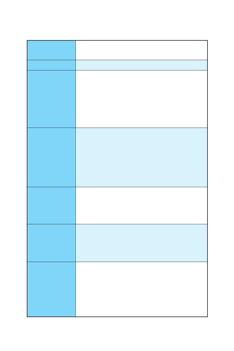
Технические характеристики
Технические характеристики
Процессор
Поддержка процессоров AMD
®
RYZEN серии и
процессоров A-серии 7-ого поколения/ Athlon
™
для
сокета AM4
Чипсет AMD
®
X370
Память
y 4x слота памяти DDR4 с поддержкой до 64ГБ
Поддержка DDR4 1866/ 2133/ 2400/ 2667(OC)/
2933(OC)/ 3200(OC)+ МГц *
y Двухканальная архитектура памяти
y Поддержка памяти non-ECC UDIMM
y Поддержка памяти ECC UDIMM (в режиме non-ECC)
* Процессоры A-серии 7-ого поколения/ Athlon
™
максимально
поддерживают 2400 МГц. Пожалуйста, обратитесь www.msi.com для
получения дополнительной информации о совместимых памяти.
Слоты
расширения
y 2x слота PCIe 3.0 x16 (PCIE_2, PCIE_4)
Процессоры RYZEN серии поддерживают режим
x16/x0, x8/x8
Процессоры A-серии 7-ого поколения/ Athlon
™
поддерживают режим x8/x0
y 1x слот PCIe 2.0 x16 (PCI_E6, поддержка режима x4)*
y 3x слота PCIe 2.0 x1
* Слот PCI_E6 будет работать как PCIe 2.0 x1 при установке устройства
в любом слоте PCIe x1.
Встроенная
графика
y 1x порт DVI-D, с поддержкой максимального
разрешения 1920×1200@60Гц, 1600×1200@60Гц*
y 1x порт HDMI
™
1.4, с поддержкой максимального
разрешения 2560×1600@60Гц*
* Поддерживается только при использовании процессоров A-серии
7-ого поколения/ Athlon
™
Поддержка Multi-
GPU
y Процессоры RYZEN серии
Поддержка технологии 2-Way NVIDIA
®
SLI
™
Поддержка технологии 3-Way AMD
®
CrossFire
™
y Процессоры A-серии 7-ого поколения/ Athlon
™
Поддержка технологии 2-Way AMD
®
CrossFire
™
Подключение
накопителей
Чипсет AMD
®
X370
y 6x портов SATA 6 Гб/с
y 1x разъем M.2 (Ключ M)
Поддержка PCIe 3.0 x4 (процессоры RYZEN
серии) или PCIe 3.0 x2 (процессоры A-серии 7-ого
поколения/ Athlon
™
) и накопителей SATA 6 Гб/с
2242/ 2260 /2280/ 22110
y Поддержка RAID 0, RAID 1 и RAID 10
Продолжение на следующей странице
5
Технические характеристики
Продолжение с предыдущей страницы
USB
y Контроллер ASMedia
®
ASM2142
1x порт USB 3.1 Gen2 (SuperSpeed USB 10Gbps) Type-C
на задней панели
1x порт USB 3.1 Gen2 (SuperSpeed USB 10Gbps) Type-A
на задней панели
y Контроллер AMD
®
X370
4x порта USB 3.1 Gen1 (SuperSpeed USB) доступны
через внутренние разъемы USB
6x портов USB 2.0 (High-speed USB) (2 порта Type-A
на задней панели, 4 порта доступны через
внутренние разъемы USB)
y Процессоры AMD
®
4x порта USB 3.1 Gen1 (SuperSpeed USB) Type-A на
задней панели
Аудио
y Realtek
®
ALC892 Codec
y 7.1-канальный High Definition Audio
LAN y 1x Гигабитный сетевой контроллер Realtek
®
8111H
Разъемы задней
панели
y 1x комбинированный порт PS/2 клавиатуры/ мыши
y 2x порта USB 2.0 Type-A
y 1x порт DVI-D
y 1x порт HDMI
™
1.4
y 1x порт LAN (RJ45)
y 4x порта USB 3.1 Gen1 Type-A
y 1x порт USB 3.1 Gen2 Type-A
y 1x порт USB 3.1 Gen2 Type-C
y 6x аудиоразъемов
Продолжение на следующей странице

6
Технические характеристики
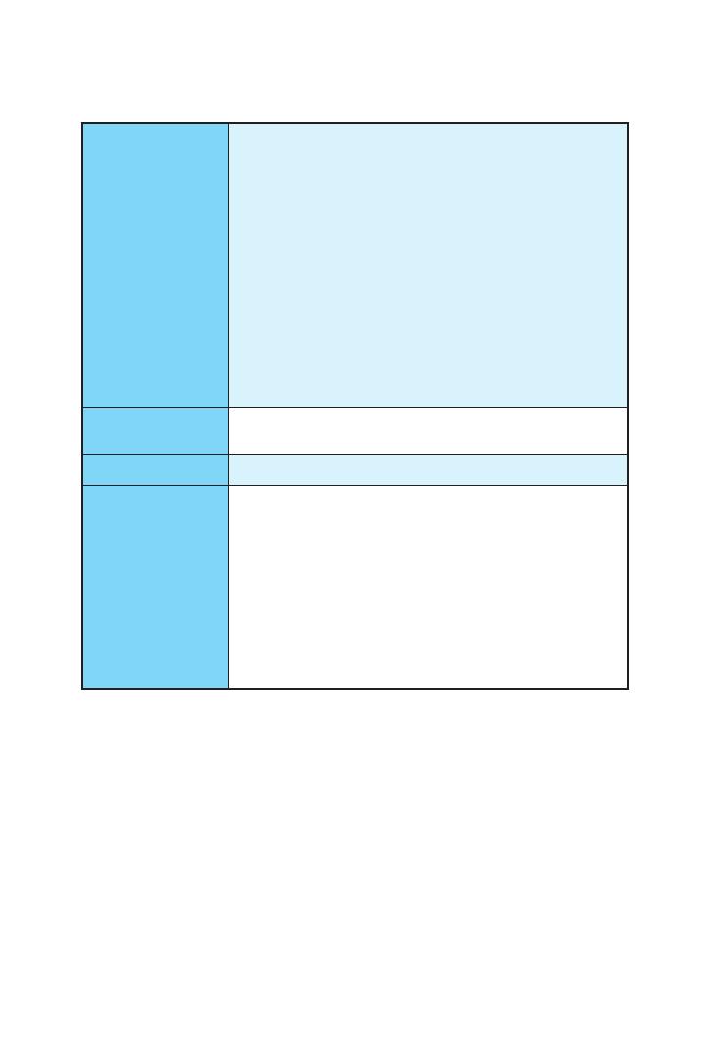
Продолжение с предыдущей страницы
Разъемы на плате
y 1x 24-контактный разъем питания ATX
y 1x 8-контактный разъем питания ATX 12В
y 6x разъемов SATA 6 Гб/с
y 2x разъема USB 2.0 (Поддержка 4-х дополнительных
портов USB 2.0)
y 2x разъема USB 3.1 Gen1 (Поддержка 4-х
дополнительных портов 4 USB 3.1 Gen1)
y 1x 4-контактный разъем вентилятора процессора
y 1x 4-контактный разъем вентилятора PUMP
(Поддержка до 2А)
y 4x 4-контактных разъема вентилятора системы
y 1x разъем RGB LED
y 1x разъем модуля TPM
y 1x разъем последовательного порта
y 1x разъем параллельного порта
y 1x аудиоразъем передней панели
y 2x разъема системной панели
y 1x разъем датчика открытия корпуса
y 1x джампер очистки данных CMOS
Контроллер
ввода—вывода
NUVOTON NCT6795D
Аппаратный
мониторинг
y Определение температуры процессора/системы
y Определение скорости вентиляторов процессора/
системы
y Управление скоростью вентиляторов процессора/
системы
Форм—фактор
y ATX Форм—фактор
y 12 x 9.6 дюйма (30.4 x 24.3 см)
Параметры BIOS
y 1x 128 Мб флэш
y UEFI AMI BIOS
y ACPI 5.0, PnP 1.0a, SM BIOS 2.8
y Мультиязычный интерфейс
Продолжение на следующей странице

7
Технические характеристики
Продолжение с предыдущей страницы
Программное
обеспечение
y Драйверы
y COMMAND CENTER
y LIVE UPDATE 6
y SUPER CHARGER
y GAMING APP
y RAMDISK
y X-BOOST
y MSI SMART TOOL
y GAMING LAN MANAGER
y DRAGON EYE
y Norton
™
Internet Security Solution
y Google Chrome
™
, Google Toolbar, Google Drive
y SteelSeries Engine 3
y CPU-Z MSI GAMING
Продолжение на следующей странице

8
Технические характеристики
Продолжение с предыдущей страницы
Эксклюзивные
функции
y VR Boost
y Audio Boost
y GAMING LAN с Gaming LAN Manager
y Turbo M.2
y Pump Fan
y Интеллектуальное управление скоростью
вращения вентиляторов
y Gaming DNA с индикатором на нижней части
y Mystic light SYNC
y Индикатор отладки EZ
y PCI-E Steel Armor
y M.2 Steel Armor
y USB type A+C
y Multi GPU – SLI Technology
y Multi GPU – CrossFire Technology
y DDR4 Boost
y GAME Boost
y Lightning USB
y Military Class 4
y 7000+ Quality Test
y GAMING HOTKEY
y GAMING MOUSE Control
y Click BIOS 5
y AMD FreeSync
™
Ready
y AMD OverDrive
™
Ready
y GAMING Certified
y SteelSeries Certified
y WTFast GPN*
Премиум лицензия на 2 мес
Мультисерверная оптимизация сети
Улучшение стабильности сетевого соединения
* Данное предложение годно только в течение ограниченного
периода, для получения дополнительной информации, посетите
www.msi.com
9
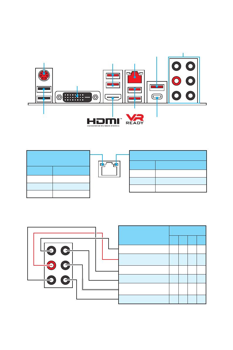
Задняя панель портов ввода/ вывода
USB 3.1 Gen2 Type-C
Подключение/ Работа
индикатора
Состояние Описание
Выкл. Не подключен
Желтый Подключен
Мигает Передача данных
Скорость передачи данных
Состояние Описание
Выкл. 10 Мбит/с подключение
Зеленый 100 Мбит/с подключение
Оранжевый 1 Гбит/с подключение
Таблица состояний индикатора порта LAN
Конфигурация портов Аудио
Задняя панель портов ввода/ вывода
PS/2
LAN
USB 2.0
Порты Аудио
DVI-D
USB 3.1 Gen1
USB 3.1 Gen1
USB 3.1 Gen2
Порты Аудио
Канал
2 4 6 8
Линейный вход
Линейный выход/ Выход
фронтальных колонок
● ● ● ●
Микрофонный вход
Тыловые колонки ● ● ●
Выход центральной
колонки/ сабвуфера
● ●
Выход боковых колонок ●
(●: подключен, Пусто: не подключен)
10
Задняя панель портов ввода/ вывода
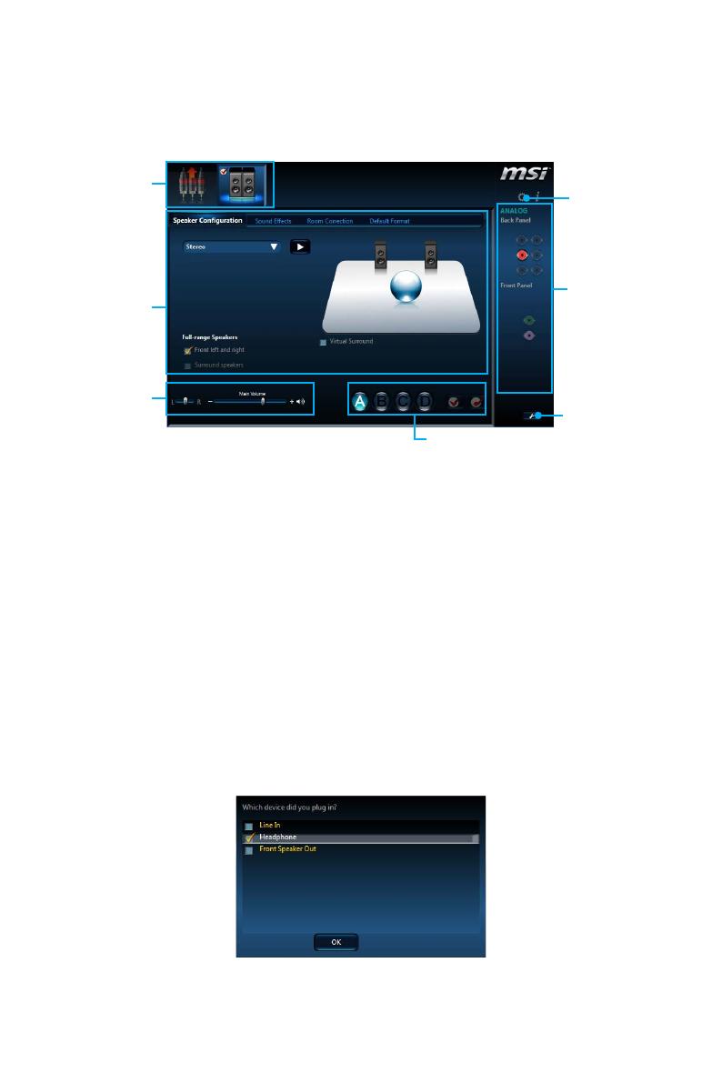
Менеджер Realtek HD Audio
После установки драйвера Realtek HD Audio, в системном трее появится
значок Realtek HD Audio Manager. Дважды щелкните по значку для запуска
приложения.
y Выбор устройства — позволяет выбрать источник аудио выхода и
изменить соответствующие параметры. Отмеченное устройство будет
использоваться по умолчанию.
y Дополнительные эффекты — это список опций по настройке звуковых
эффектов для входного и выходного сигнала аудио устройства.
y Мастер—громкость — регулирует громкость или баланс правой и левой
колонок, подключенных к передней или задней панели.
y Профили — позволяют переключаться между различными профилями.
y Расширенные настройки — обеспечивают работу с двумя независимыми
потоками аудио.
y Состояние разъемов — отображает все устройства воспроизведения и
записи, подключенные к компьютеру.
y Настройки подключений — настраивают параметры подключения.
Автоматическое всплывающее диалоговое окно
При подключении устройства к разъему аудио появится диалоговое окно с
просьбой подтвердить подключенное устройство.
Каждый разъем соответствует его настройкам по умолчанию, как показано
на следующей странице.
Выбор
устройства
Мастер—
громкость
Дополнительные
эффекты
Состояние
разъемов
Настройки
подключений
Расширенные
настройки
Профили
11
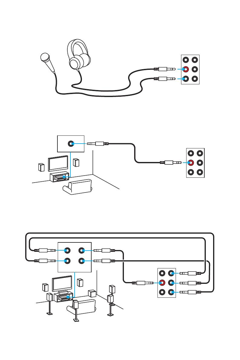
Задняя панель портов ввода/ вывода
Подключение наушников и микрофона
Подключение внешнего стерео усилителя (колонок)
Подключение звуковой системы 7.1
AUDIO INPUT
AUDIO INPUT
Rear Front
Side Center/
Subwoofer
12
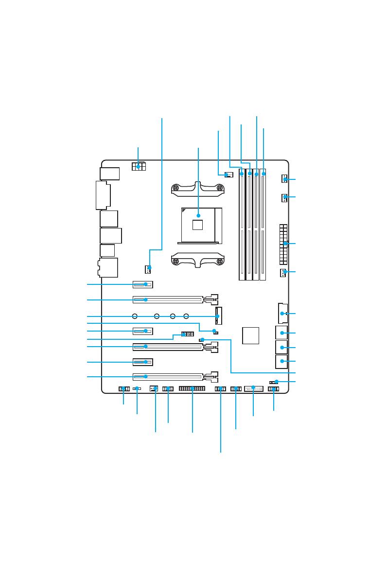
Компоненты материнской платы
Компоненты материнской платы
SATA▼3▲4
SATA▼1▲2
SATA▼5▲6
CPU_FAN1
PUMP_FAN1
PCI_E1
PCI_E2
PCI_E3
PCI_E4
PCI_E5
PCI_E6
JTPM1
Процессорный
сокет
CPU_PWR1
JBAT1
M2_1
DIMMA1
SYS_FAN1
SYS_FAN4
DIMMA2
DIMMB1
DIMMB2
JUSB1
JUSB3
JCOM1
JUSB2
JFP2
JFP1
JAUD1
JLED1
SYS_FAN2
JLPT1
ATX_PWR1
SYS_FAN3
JUSB4
JCI1
13
Компоненты материнской платы
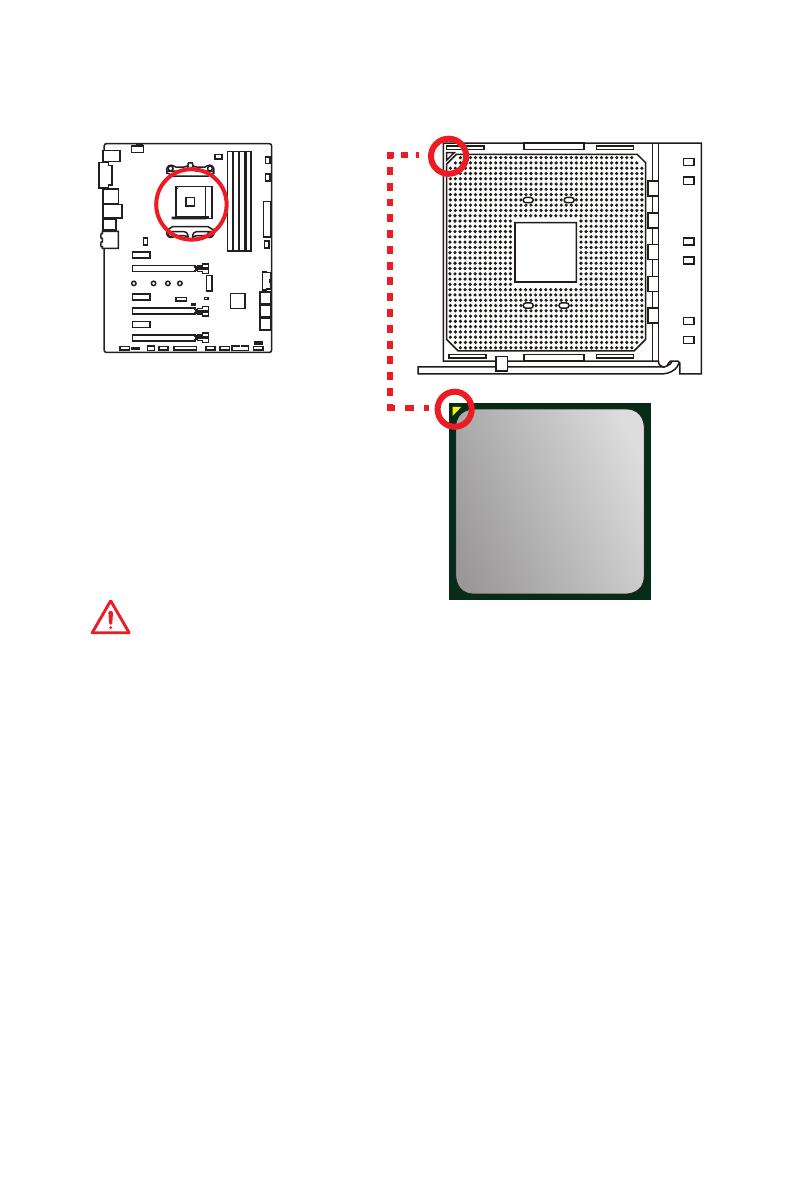
Процессорный сокет
Внимание!
y
Из—за особенностей архитектуры процессоров АМ4, замена процессора
может привести к сбросу настроек BIOS до значений по умолчанию.
y
Перед установкой или заменой процессора, необходимо отключить
кабель питания.
y
При установке процессора обязательно установите процессорный
кулер. Кулер, представляющий собой систему охлаждения процессора,
предотвращает перегрев и обеспечивает стабильную работу системы.
y
Перед включением системы проверьте герметичность соединения между
процессором и радиатором.
y
Перегрев может привести к серьезному повреждению процессора и
материнской платы. Всегда проверяйте работоспособность вентилятора
для защиты процессора от перегрева. При установке кулера нанесите
ровный слой термопасты (или термоленту) на крышку установленного
процессора для улучшения теплопередачи.
y
Если вы приобрели отдельно процессор и процессорный кулер,
подробное описание установки см. в документации в данному кулеру.
y
Данная системная плата разработана с учетом возможности ее
«разгона». Перед выполнением разгона системы убедитесь в том,
что все компоненты системы смогут его выдержать. Производитель
не рекомендует использовать параметры, выходящие за пределы
технических характеристик устройств. Гарантия MSI
®
не распространяется
на повреждения и другие возможные последствия ненадлежащей
эксплуатации оборудования.
Процессор AM4
На поверхности процессора AM4
имеется золотой треугольник
для правильной установки
процессора относительно
процессорного сокета
материнской платы. Золотой
треугольник указывает на
контакт 1.
14
Компоненты материнской платы
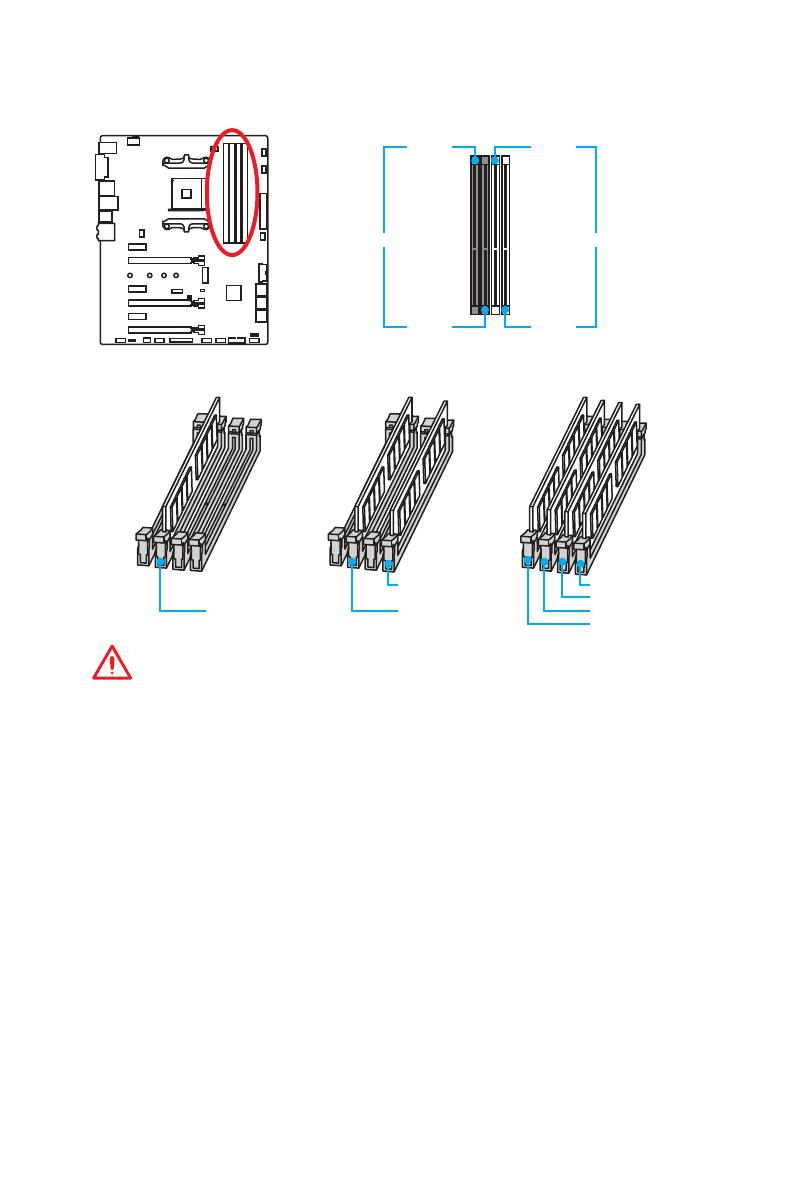
Слоты DIMM
DIMMA1 DIMMB1
Канал A Канал B
DIMMA2 DIMMB2
Рекомендации по установке модулей памяти
Внимание!
y
Всегда устанавливайте модуль памяти сначала в слот DIMMA2.
y
В связи со спецификой использования ресурсов чипсета, доступный
объем памяти будет немного меньше, чем фактически установленный.
y
На основе характеристик процессора, рекомендуется устанавливать
напряжение на памяти DIMM менее 1.35 В. Это позволит защитить
процессор.
y
Некоторые модули памяти при разгоне могут работать на частотах ниже
заявленной производителем, поскольку выставляемая для памяти частота
зависит от информации, записанной в SPD (Serial Presence Detect). Зайдите
в BIOS и выберите опцию DRAM Frequency!, чтобы установить заявленную
или более высокую частоту.
y
При установке памяти во все слоты, а также при ее разгоне,
рекомендуется использовать более эффективную систему охлаждения
памяти.
y
Совместимость и стабильность работы установленного модуля памяти
при разгоне зависит от установленного процессора и других устройств.
y
Из—за ограничений процессора AM4/контроллера памяти, модули памяти
могут работать на частотах ниже заявленной производителем в состоянии
по умолчанию. Дополнительную информацию о совместимых модулях
памяти можно найти на веб—сайте www.msi.com.
DIMMB2 DIMMB2
DIMMB1
DIMMA2 DIMMA2 DIMMA2
DIMMA1
15
Компоненты материнской платы
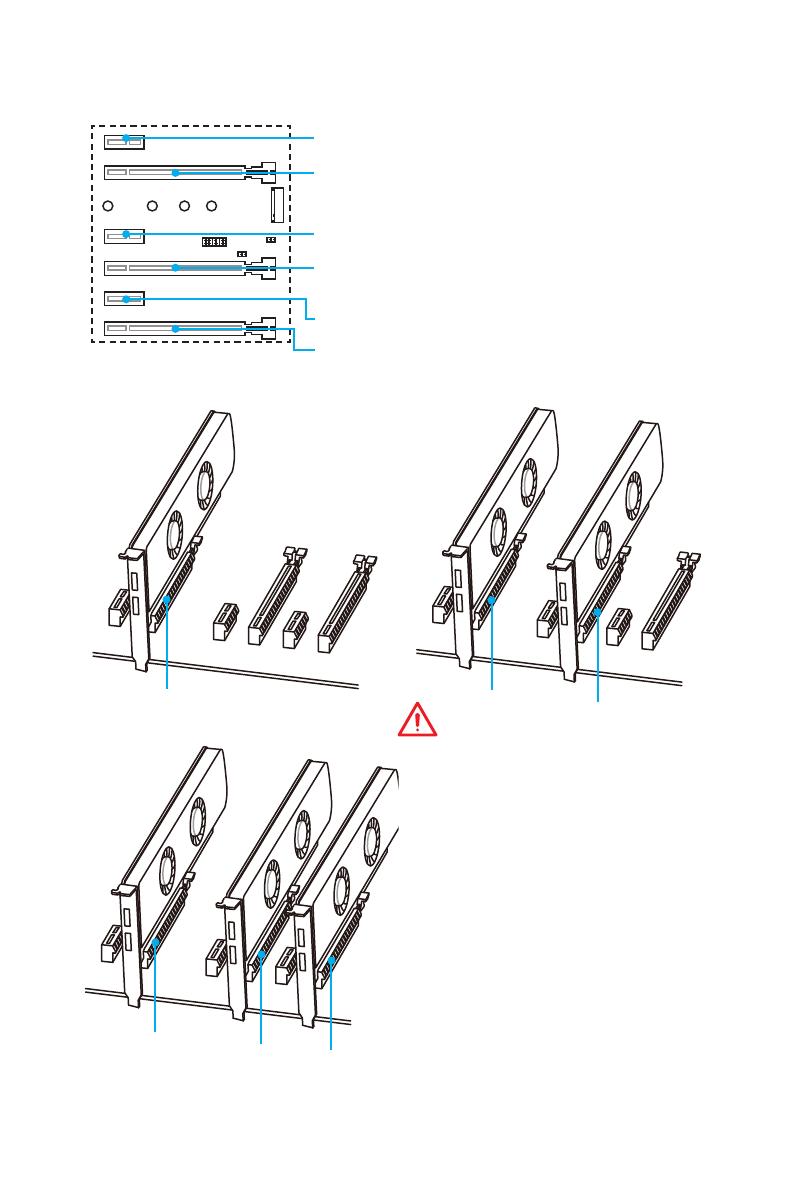
PCI_E1~6: Слоты расширения PCIe
Рекомендации по установке нескольких видеокарт (процессоры
RYZEN серии)
x16
x8
x8
x8
x8
x4
Внимание!
y
При установке массивной видеокарты,
необходимо использовать такой
инструмент, как MSI Gaming Series
Graphics Card Bolster для поддержки
веса графической карты и во
избежание деформации слота.
y
Для установки одной карты
расширения PCIe x16 с оптимальной
производительностью рекомендуется
использовать слот PCI_E2.
y
Перед установкой или извлечением
плат расширения убедитесь, что
кабель питания отключен от
электрической сети. Прочтите
документацию на карту расширения
и выполните необходимые
дополнительные аппаратные или
программные изменения для данной
карты.
PCI_E1: PCIe 2.0 x1
PCI_E3: PCIe 2.0 x1
PCI_E5: PCIe 2.0 x1
PCI_E6: PCIe 2.0 x4
PCI_E2: PCIe 3.0 x16 (для процессоров RYZEN серии)
PCIe 3.0 x8 (для процессоров A-серии 7-ого
поколения/ Athlon
™
)
PCI_E4: PCIe 3.0 x8 (только для процессоров RYZEN
серии) Недоступно для процессоров
A-серии 7-ого поколения/ Athlon
™
16
Компоненты материнской платы
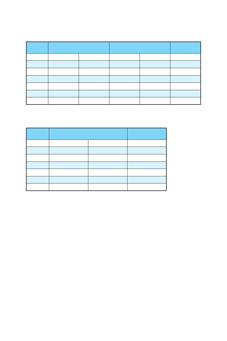
Таблица пропускной способности PCIe
Для процессоров RYZEN серии
Слот
Одна карта
расширения
2-Way 3-Way
PCI_E1 ─ Gen 2.0 x 1 ─ Gen 2.0 x 1 ─
PCI_E2 Gen 3.0 x 16* Gen 3.0 x 16* Gen 3.0 x 8* Gen 3.0 x 8* Gen 3.0 x 8*
PCI_E3 ─ Gen 2.0 x 1 ─ Gen 2.0 x 1 ─
PCI_E4 ─ ─ Gen 3.0 x 8* Gen 3.0 x 8* Gen 3.0 x 8*
PCI_E5 ─ Gen 2.0 x 1 ─ Gen 2.0 x 1 ─
PCI_E6 Gen 2.0 x 4 Gen 2.0 x 1 Gen 2.0 x 4 Gen 2.0 x 1 Gen 2.0 x 4*
M2_1 Gen 3.0 x 4 Gen 3.0 x 4 Gen 3.0 x 4 Gen 3.0 x 4 Gen 3.0 x 4
(─: пусто, *: видеокарта)
Для процессоров A-серии 7-ого поколения/ Athlon
™
Слот
Одна карта
расширения
2-Way
PCI_E1 ─ Gen 2.0 x 1 ─
PCI_E2 Gen 3.0 x 8* Gen 3.0 x 8* Gen 3.0 x 8*
PCI_E3 ─ Gen 2.0 x 1 ─
PCI_E4 ─ ─ ─
PCI_E5 ─ Gen 2.0 x 1 ─
PCI_E6 Gen 2.0 x 4 Gen 2.0 x 1 Gen 2.0 x 4*
M2_1 Gen 3.0 x 2 Gen 3.0 x 2 Gen 3.0 x 2
(─: пусто, *: видеокарта)
17
Компоненты материнской платы
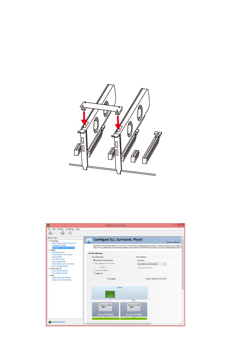
Установка видеокарт в режиме SLI
Для выполнения рекоммендаций по питанию видеокарт в SLI
конфигурациях, пожалуйста, обратитесь к руководству пользователя вашей
видеокарты, чтобы убедиться, что она соответствует всем требованиям
системы.
Для установки видеокарт в SLI:
1. Выключите компьютер и отсоедините шнур питания. Установите две
видеокарты в слот PCI_E2 и PCI_E4.
2. Соедините видеокарты разъемом SLI Bridge.
3. Подключите все разъемы питания PCIe видеокарт.
4. Подключите кабель питания, включите компьютер, установите драйверы
и программное обеспечение из комплекта поставки видеокарты.
5. Щелкните правой кнопкой мыши на Рабочем столе Windows и выберите
NVIDIA Control Panel из раскрывшегося меню. Нажмите на Configure
SLI, Surround, PhysX в левой панели задач и выберите Maximize 3D
performance в меню конфигурации SLI, а затем нажмите кнопку Apply.
18
Компоненты материнской платы
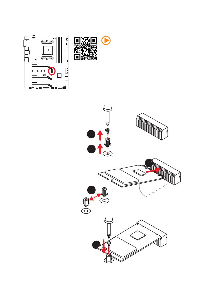
M2_1: Разъем M.2 (Ключ M)
Видео Инструкция
Смотрите видео, чтобы узнать как
установить модуль M.2.
http://youtu.be/JCTFABytrYA
Установка модуля M.2
1
2
3
30°
3. Закрутите стойку
в отверстие,
на расстоянии,
соответствующем
длине вашего модуля
М.2.
4. Вставьте модуль М.2 в
разъем М.2 под углом
30 градусов.
5. Совместите винт с
выемкой на задней
кромке модуля M.2 и
закрутите его в стойку.
1. Выкрутите винт из
стойки.
2. Выкрутите стойку.
4
5
19
Компоненты материнской платы
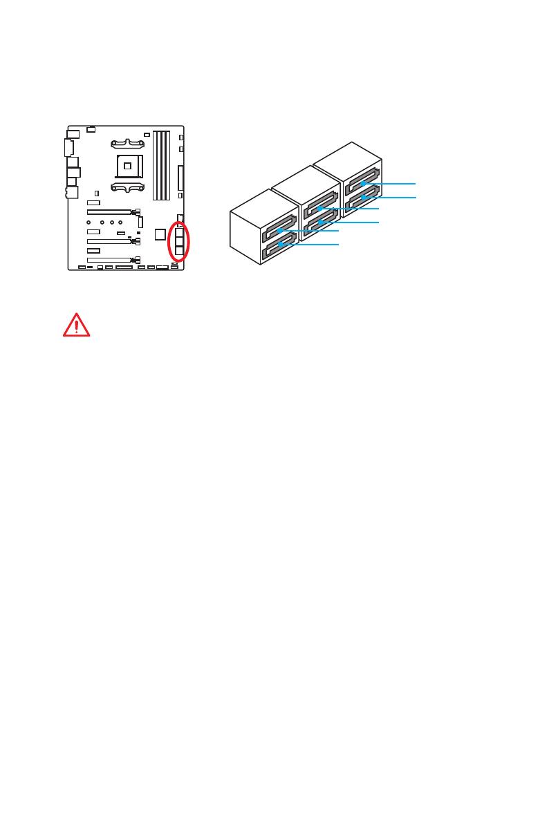
SATA1~6: Разъемы SATA 6 Гб/с
Эти разъемы представляют собой интерфейсные порты SATA 6 Гб/с. К
каждому порту можно подключить одно устройство SATA.
Внимание!
y
Избегайте перегибов кабеля SATA под прямым углом. В противном случае,
возможна потеря данных при передаче.
y
Кабели SATA оснащены одинаковыми коннекторами с обеих сторон.
Однако, для экономии занимаемого пространства к материнской плате
рекомендуется подключать плоский разъем.
SATA5
SATA1
SATA3
SATA6
SATA2
SATA4
/
на других языках
Похожие модели бренда
Это руководство также подходит для
Устройство:
MSi X370 GAMING PLUS
Производитель: MSi
Размер: 11,7 MB
Добавлено: 2023-05-15
Количество страниц: 158
Как пользоваться?
Наша цель — обеспечить Вам самый быстрый доступ к руководству по эксплуатации устройства MSi X370 GAMING PLUS. Пользуясь просмотром онлайн Вы можете быстро просмотреть содержание и перейти на страницу, на которой найдете решение своей проблемы с MSi X370 GAMING PLUS.
Для Вашего удобства
Если просмотр руководства MSi X370 GAMING PLUS непосредственно на этой странице для Вас неудобен, Вы можете воспользоваться двумя возможными решениями:
- Полноэкранный просмотр -, Чтобы удобно просматривать инструкцию (без скачивания на компьютер) Вы можете использовать режим полноэкранного просмотра. Чтобы запустить просмотр инструкции MSi X370 GAMING PLUS на полном экране, используйте кнопку Полный экран.
- Скачивание на компьютер — Вы можете также скачать инструкцию MSi X370 GAMING PLUS на свой компьютер и сохранить ее в своем архиве. Если ты все же не хотите занимать место на своем устройстве, Вы всегда можете скачать ее из ManualsBase.
MSi X370 GAMING PLUS Руководство пользователя — Online PDF
Ознакомьтесь с подробным руководством пользователя для замечательного творения MSi, модель X370 GAMING PLUS. Получите ценную информацию и инструкции, чтобы максимально использовать возможности вашего устройства и оптимизировать взаимодействие с пользователем. Раскройте весь потенциал своего устройства MSi X370 GAMING PLUS с помощью этого подробного руководства пользователя, в котором содержатся пошаговые инструкции и советы экспертов, которые сделают работу с ним легкой и приятной.
Печатная версия
Многие предпочитают читать документы не на экране, а в печатной версии. Опция распечатки инструкции также предусмотрена и Вы можете воспользоваться ею нажав на ссылку, находящуюся выше — Печатать инструкцию. Вам не обязательно печатать всю инструкцию MSi X370 GAMING PLUS а только некоторые страницы. Берегите бумагу.
Резюме
Ниже Вы найдете заявки которые находятся на очередных страницах инструкции для MSi X370 GAMING PLUS. Если Вы хотите быстро просмотреть содержимое страниц, которые находятся на очередных страницах инструкции, Вы воспользоваться ими.

Unpacking Thank you for buying the MSI® X370 GAMING PLUS motherboard. Check to make sure your motherboard box contains the following items. If something is missing, contact your dealer as soon as possible. Drivers & Utilities Disc Motherboard User Guide SATA Cable x2 SATA Cable Labels Motherboard I/O Shield SLI Bridge Connector Unpacking 1 Safety Information y The components included in this package are prone to damage from electrostatic discharge (ESD). Please adhere to the following instructions to ensure successful computer assembly. y Ensure that all components are securely connected. Loose connections may cause the computer to not recognize a component or fail to start. y Hold the motherboard by the edges to avoid touching sensitive components. y It is recommended to wear an electrostatic discharge (ESD) wrist strap when handling the motherboard to prevent electrostatic damage. If an ESD wrist strap is not available, discharge yourself of static electricity by touching another metal object before handling the motherboard. y Store the motherboard in an electrostatic shielding container or on an anti-static pad whenever the motherboard is not installed. y Before turning on the computer, ensure that there are no loose screws or metal components on the motherboard or anywhere within the computer case. y Do not boot the computer before installation is completed. This could cause permanent damage to the components as well as injury to the user. y If you need help during any installation step, please consult a certified computer technician. y Always turn off the power supply and unplug the power cord from the power outlet before installing or removing any computer component. y Keep this user guide for future reference. y Keep this motherboard away from humidity. y Make sure that your electrical outlet provides the same voltage as is indicated on the PSU, before connecting the PSU to the electrical outlet. y Place the power cord such a way that people can not step on it. Do not place anything over the power cord. y All cautions and warnings on the motherboard should be noted. y If any of the following situations arises, get the motherboard checked by service personnel: Liquid has penetrated into the computer. The motherboard has been exposed to moisture. The motherboard does not work well or you can not get it work according to user guide. The motherboard has been dropped and damaged. The motherboard has obvious sign of breakage. y Do not leave this motherboard in an environment above 60°C (140°F), it may damage the motherboard. 2 Safety Information Quick Start Preparing Tools and Components AMD® AM4 CPU Thermal Paste CPU Fan DDR4 Memory Power Supply Unit Chassis SATA DVD Drive Phillips Screwdriver SATA Hard Disk Drive Graphics Card A Package of Screws Quick Start 3 Installing a Processor 1 3 2 5 4 6 8 9 7 4 Quick Start Installing DDR4 memory 1 1 2 3 2 3 DIMMB2 DIMMA2 DIMMA2 DIMMB2 DIMMB1 DIMMA2 DIMMA1 Quick Start 5 Connecting the Front Panel Header - ED D+ LE ED DL 1 9 JFP1 1 HDD LED + 2 3 HDD LED - 4 Power LED + Power LED - 5 Reset Switch 6 Power Switch 7 Reset Switch 8 Power Switch 9 Reserved 10 No Pin RESET SW 10 HDD LED W TS SE RE PO HD SW ER PO W R WE RL WE PO 2 JFP1 HDD LED POWER LED 6 Quick Start HDD LED HDD LED + POWER LED POWER LED + Installing the Motherboard 1 2 Quick Start 7 Installing SATA Drives 1 2 3 5 4 8 Quick Start Installing a Graphics Card 1 3 2 5 4 6 Quick Start 9 Connecting Peripheral Devices 10 Quick Start Connecting the Power Connectors ATX_PWR1 CPU_PWR1 Quick Start 11 Power On 1 2 3 4 12 Quick Start Contents Unpacking .............................................................................................................. 1 Safety Information ................................................................................................. 2 Quick Start ............................................................................................................. 3 Preparing Tools and Components .......................................................................... 3 Installing a Processor ............................................................................................. 4 Installing DDR4 memory ........................................................................................ 5 Connecting the Front Panel Header ....................................................................... 6 Installing the Motherboard ..................................................................................... 7 Installing SATA Drives............................................................................................. 8 Installing a Graphics Card ...................................................................................... 9 Connecting Peripheral Devices ............................................................................ 10 Connecting the Power Connectors....................................................................... 11 Power On............................................................................................................... 12 Specifications....................................................................................................... 15 Block Diagram .................................................................................................... 20 Rear I/O Panel ..................................................................................................... 21 LAN Port LED Status Table................................................................................... 21 Audio Ports Configuration .................................................................................... 21 Realtek HD Audio Manager .................................................................................. 22 Overview of Components .................................................................................... 24 CPU Socket ........................................................................................................... 26 DIMM Slots............................................................................................................ 27 PCI_E1~6: PCIe Expansion Slots .......................................................................... 28 M2_1: M.2 Slot (Key M) ......................................................................................... 31 SATA1~6: SATA 6Gb/s Connectors ....................................................................... 32 CPU_PWR1, ATX_PWR1: Power Connectors ....................................................... 33 JUSB1~2: USB 2.0 Connectors ............................................................................. 34 JUSB3~4: USB 3.1 Gen1 Connectors ................................................................... 34 CPU_FAN1, PUMP_FAN1, SYS_FAN1~4: Fan Connectors ................................... 35 JAUD1: Front Audio Connector ............................................................................ 36 JCI1: Chassis Intrusion Connector ....................................................................... 36 JFP1, JFP2: Front Panel Connectors ................................................................... 37 JTPM1: TPM Module Connector ........................................................................... 37 JBAT1: Clear CMOS (Reset BIOS) Jumper ........................................................... 38 JLPT1: Parallel Port Connector ........................................................................... 38 JCOM1: Serial Port Connector ............................................................................. 39 Contents 13 JLED1: RGB LED connector ................................................................................. 39 Onboard LEDs ...................................................................................................... 40 EZ Debug LED ....................................................................................................... 40 DIMM LEDs ........................................................................................................... 40 GPU LED ............................................................................................................... 40 PCIe x16 slot LEDs................................................................................................ 40 BIOS Setup ........................................................................................................... 41 Entering BIOS Setup ............................................................................................. 41 Resetting BIOS...................................................................................................... 42 Updating BIOS....................................................................................................... 42 Advanced Mode .................................................................................................... 45 SETTINGS.............................................................................................................. 46 Advanced ............................................................................................................... 46 Boot ....................................................................................................................... 51 Security ................................................................................................................. 52 Save & Exit ............................................................................................................ 53 OC.......................................................................................................................... 55 M-FLASH .............................................................................................................. 58 OC PROFILE .......................................................................................................... 59 HARDWARE MONITOR .......................................................................................... 60 Software Description........................................................................................... 61 Installing Windows® 7 64-bit/ Windows®10 64-bit ............................................... 61 Installing Drivers .................................................................................................. 61 Installing Utilities ................................................................................................. 61 LIVE UPDATE 6...................................................................................................... 62 COMMAND CENTER ............................................................................................. 64 GAMING APP ......................................................................................................... 68 RAMDISK............................................................................................................... 73 X-BOOST ............................................................................................................... 74 MSI SMART TOOL ................................................................................................. 76 GAMING LAN MANAGER ...................................................................................... 78 DRAGON EYE ........................................................................................................ 80 SteelSeries Engine 3 ............................................................................................ 81 CPU-Z.................................................................................................................... 83 Troubleshooting .................................................................................................. 84 Regulatory Notices .............................................................................................. 85 14 Contents Specifications CPU Supports AMD® RYZEN series processors and 7th Gen A-series/ Athlon™ processors for Socket AM4 Chipset AMD® X370 Chipset y 4x DDR4 memory slots, support up to 64GB Supports DDR4 1866/ 2133/ 2400/ 2667(OC)/ 2933(OC)/ 3200(OC)+ Mhz * Memory y Dual channel memory architecture y Supports non-ECC UDIMM memory y Supports ECC UDIMM memory (non-ECC mode) * 7th Gen A-series/ Athlon ™ processors support a maximum of 2400 MHz. Please refer www.msi.com for more information on compatible memory y 2x PCIe 3.0 x16 slots (PCIE_2, PCIE_4) RYZEN series processors support x16/x0, x8/x8 mode Expansion Slots 7th Gen A-series/ Athlon™ processors support x8/x0 mode y 1x PCIe 2.0 x16 slot (PCIE_6, supports x4 mode)* y 3x PCIe 2.0 x1 slots * PCI_E6 slot will be PCIe 2.0 x1 when installing device in any PCIe x1 slot. y 1x DVI-D port, supporting a maximum resolution of 1920x1200@60Hz, 1600x1200@60Hz* Onboard Graphics y 1x HDMI™ 1.4 port, supports a maximum resolution of 2560x1600@60Hz* * Only support when using a 7th Gen A-series/ Athlon™ processors y RYZEN series processor Supports 2-Way NVIDIA® SLI™ Technology Multi-GPU Supports 3-Way AMD® CrossFire™ Technology y 7th Gen A-series/ Athlon™ processor Supports 2-Way AMD® CrossFire™ Technology AMD® X370 Chipset y 6x SATA 6Gb/s ports Storage y 1x M.2 port (Key M) Supports PCIe 3.0 x4 (RYZEN series processor) or PCIe 3.0 x2 (7th Gen A-series/ Athlon™ processors) and SATA 6Gb/s 2242/ 2260 /2280/ 22110 storage devices y Supports RAID 0, RAID 1 and RAID 10 Continued on next page Specifications 15 Continued from previous page y ASMedia® ASM2142 Chipset 1x USB 3.1 Gen2 (SuperSpeed USB 10Gbps) Type-C port on the back panel 1x USB 3.1 Gen2 (SuperSpeed USB 10Gbps) Type-A port on the back panel y AMD® X370 Chipset USB 4x USB 3.1 Gen1 (SuperSpeed USB) ports available through the internal USB connectors 6x USB 2.0 (High-speed USB) ports (2 Type-A ports on the back panel, 4 ports available through the internal USB connectors) y AMD® CPU 4x USB 3.1 Gen1 (SuperSpeed USB) Type-A ports on the back panel Audio LAN y Realtek® ALC892 Codec y 7.1-Channel High Definition Audio y 1x Realtek® 8111H Gigabit LAN controller y 1x PS/2 keyboard/ mouse combo port y 2x USB 2.0 Type-A ports y 1x DVI-D port Back Panel Connectors y 1x HDMI™ 1.4 port y 1x LAN (RJ45) port y 4x USB 3.1 Gen1 Type-A ports y 1x USB 3.1 Gen2 Type-A port y 1x USB 3.1 Gen2 Type-C port y 6x audio jacks Continued on next page 16 Specifications Continued from previous page y 1x 24-pin ATX 12V power connector y 1x 8-pin ATX 12V power connector y 6x SATA 6Gb/s connectors y 2x USB 2.0 connectors (support additional 4 USB 2.0 ports) y 2x USB 3.1 Gen1 connectors (support additional 4 USB 3.1 Gen1 ports) y 1x 4-pin CPU fan connector y 1x 4-pin PUMP fan connector (supports up to 2A) Internal Connectors y 4x 4-pin system fan connectors y 1x RGB LED connector y 1x TPM module connector y 1x Serial port connector y 1x Parallel port connector y 1x Front panel audio connector y 2x System panel connectors y 1x Chassis Intrusion connector y 1x Clear CMOS jumper I/O Controller NUVOTON NCT6795D Controller Chip y CPU/System temperature detection Hardware Monitor y CPU/System fan speed detection y CPU/System fan speed control Form Factor y ATX Form Factor y 12 in. x 9.6 in. (30.4 cm x 24.3 cm) y 1x 128 Mb flash BIOS Features y UEFI AMI BIOS y ACPI 5.0, PnP 1.0a, SM BIOS 2.8 y Multi-language Continued on next page Specifications 17 Continued from previous page y Drivers y COMMAND CENTER y LIVE UPDATE 6 y SUPER CHARGER y GAMING APP y RAMDISK Software y X-BOOST y MSI SMART TOOL y GAMING LAN MANAGER y DRAGON EYE y Norton™ Internet Security Solution y Google Chrome™, Google Toolbar, Google Drive y SteelSeries Engine 3 y CPU-Z MSI GAMING Continued on next page 18 Specifications Continued from previous page y VR Boost y Audio Boost y GAMING LAN with Gaming LAN Manager y Turbo M.2 y Pump Fan y Smart Fan Control y Gaming DNA with bottom LED y Mystic light SYNC y EZ debug LED y PCI-E Steel Armor y M.2 Steel Armor y USB with type A+C y Multi GPU – SLI Technology y Multi GPU – CrossFire Technology y DDR4 Boost Special Features y GAME Boost y Lightning USB y Military Class 4 y 7000+ Quality Test y GAMING HOTKEY y GAMING MOUSE Control y Click BIOS 5 y AMD FreeSync™ Ready y AMD OverDrive™ Ready y GAMING Certified y SteelSeries Certified y WTFast GPN* 2-Month Premium License Multi-Server Network Optimization Advanced Lag Spike & Disconnect Reduction * This offer is valid for a limited period only, for more information please visit www.msi.com Specifications 19 Block Diagram HDMI DVI-D 2 Channel DDR4 Memory CPU 1 x M.2 PCI Express Bus PCIex4 4 x USB 3.1 Gen1 Realtek ALC892 Audio Jacks NV6795 Super I/O P/S2 Mouse / Keyboard PCIe x1 slot Switch PCIe x1 slot PCIe x1 slot PCIe x16 slot (support x4 mode) 6 x SATA 6Gb/s 4 x USB 3.1 Gen1 X370 ASMEDIA ASM2142 6 x USB 2.0 Realtek RTL8111H 20 Block Diagram 2 x USB 3.1 Gen2 Rear I/O Panel USB 3.1 Gen2 PS/2 Audio Ports USB 3.1 Gen1 LAN DVI-D USB 3.1 Gen1 USB 2.0 USB 3.1 Gen2 Type-C LAN Port LED Status Table Link/ Activity LED Speed LED Status Description Status Description Off No link Off 10 Mbps connection Yellow Linked Green 100 Mbps connection Blinking Data activity Orange 1 Gbps connection Audio Ports Configuration Audio Ports Channel 2 4 6 8 ● ● ● ● ● ● ● Line-In Line-Out/ Front Speaker Out Mic In Rear Speaker Out Center/ Subwoofer Out Side Speaker Out (●: connected, Blank: empty) ● ● ● Rear I/O Panel 21 Realtek HD Audio Manager After installing the Realtek HD Audio driver, the Realtek HD Audio Manager icon will appear in the system tray. Double click on the icon to launch. Device Selection Advanced Settings Jack Status Application Enhancement Main Volume Connector Strings Profiles y Device Selection - allows you to select a audio output source to change the related options. The check sign indicates the devices as default. y Application Enhancement - the array of options will provide you a complete guidance of anticipated sound effect for both output and input device. y Main Volume - controls the volume or balance the right/left side of the speakers that you plugged in front or rear panel by adjust the bar. y Profiles - toggles between profiles. y Advanced Settings - provides the mechanism to deal with 2 independent audio streams. y Jack Status - depicts all render and capture devices currently connected with your computer. y Connector Settings - configures the connection settings. Auto popup dialog When you plug into a device at an audio jack, a dialogue window will pop up asking you which device is current connected. Each jack corresponds to its default setting as shown on the next page. 22 Rear I/O Panel Audio jacks to headphone and microphone diagram Audio jacks to stereo speakers diagram AUDIO INPUT Audio jacks to 7.1-channel speakers diagram AUDIO INPUT Rear Front Side Center/ Subwoofer Rear I/O Panel 23 Overview of Components DIMMA1 DIMMB1 SYS_FAN1 DIMMA2 CPU_FAN1 CPU_PWR1 DIMMB2 CPU Socket PUMP_FAN1 SYS_FAN3 ATX_PWR1 SYS_FAN4 PCI_E1 PCI_E2 JUSB4 M2_1 JBAT1 PCI_E3 JTPM1 PCI_E4 SATA▼5▲6 PCI_E5 SATA▼3▲4 SATA▼1▲2 JCI1 PCI_E6 JFP2 JAUD1 JLED1 JUSB3 JCOM1 SYS_FAN2 JLPT1 JUSB2 JUSB1 24 Overview of Components JFP1 Component Contents Port Name Port Type Page CPU_FAN1, PUMP_FAN1, SYS_FAN1~4 Fan Connectors 35 CPU_PWR1, ATX_PWR1 Power Connectors 33 CPU Socket AM4 CPU Socket 26 DIMMA1, DIMMA2, DIMMB1, DIMMB2 DIMM Slots 27 JAUD1 Front Audio Connector 36 JBAT1 Clear CMOS (Reset BIOS) Jumper 38 JCI1 Chassis Intrusion Connector 36 JCOM1 Serial Port Connector 39 JFP1, JFP2 Front Panel Connectors 37 JLED1 RGB LED connector 39 JLPT1 Parallel Port Connector 38 JTPM1 TPM Module Connector 37 JUSB1~2 USB 2.0 Connectors 34 JUSB3~4 USB 3.1 Gen1 Connectors 34 M2_1 M.2 Slot (Key M) 31 PCI_E1~6 PCIe Expansion Slots 28 SATA1~6 SATA 6Gb/s Connectors 32 Overview of Components 25 CPU Socket Introduction to the AM4 CPU The surface of the AM4 CPU has a yellow triangle to assist in correctly lining up the CPU for motherboard placement. The yellow triangle is the Pin 1 indicator. Important y When changing the processor, the system configuration could be cleared and reset BIOS to default values, due to the AM4 processor’s architecture. y Always unplug the power cord from the power outlet before installing or removing the CPU. y When installing a CPU, always remember to install a CPU heatsink. A CPU heatsink is necessary to prevent overheating and maintain system stability. y Confirm that the CPU heatsink has formed a tight seal with the CPU before booting your system. y Overheating can seriously damage the CPU and motherboard. Always make sure the cooling fans work properly to protect the CPU from overheating. Be sure to apply an even layer of thermal paste (or thermal tape) between the CPU and the heatsink to enhance heat dissipation. y If you purchased a separate CPU and heatsink/ cooler, Please refer to the documentation in the heatsink/ cooler package for more details about installation. y This motherboard is designed to support overclocking. Before attempting to overclock, please make sure that all other system components can tolerate overclocking. Any attempt to operate beyond product specifications is not recommended. MSI® does not guarantee the damages or risks caused by inadequate operation beyond product specifications. 26 Overview of Components DIMM Slots DIMMA1 Channel A DIMMA2 DIMMB1 Channel B DIMMB2 Memory module installation recommendation DIMMB2 DIMMA2 DIMMA2 DIMMB2 DIMMB1 DIMMA2 DIMMA1 Important y Always insert memory modules in the DIMMA2 slot first. y Due to chipset resource usage, the available capacity of memory will be a little less than the amount of installed. y Based on the processor specification, the Memory DIMM voltage below 1.35V is suggested to protect the processor. y Some memory modules may operate at a lower frequency than the marked value when overclocking due to the memory frequency operates dependent on its Serial Presence Detect (SPD). Go to BIOS and find the DRAM Frequency to set the memory frequency if you want to operate the memory at the marked or at a higher frequency. y It is recommended to use a more efficient memory cooling system for full DIMMs installation or overclocking. y The stability and compatibility of installed memory module depend on installed CPU and devices when overclocking. y Due to AM4 CPU/memory controller official specification limitation, the frequency of memory modules may operate lower than the marked value under the default state. Please refer www.msi.com for more information on compatible memory. Overview of Components 27 PCI_E1~6: PCIe Expansion Slots PCI_E1: PCIe 2.0 x1 PCI_E2: PCIe 3.0 x16 (RYZEN series processors) PCIe 3.0 x8 (7th Gen A-series/ Athlon™ processors) PCI_E3: PCIe 2.0 x1 PCI_E4: PCIe 3.0 x8 (RYZEN series processors) Unavailable for 7th Gen A-series/ Athlon™ processors PCI_E5: PCIe 2.0 x1 PCI_E6: PCIe 2.0 x4 Multiple graphics cards installation recommendation (RYZEN series processors) x16 x8 x8 Important y If you install a large and heavy graphics card, you need to use a tool such as MSI Gaming Series Graphics Card Bolster to support its weight to prevent deformation of the slot. y For a single PCIe x16 expansion card installation with optimum performance, using the PCI_E2 slot is recommended. x8 28 Overview of Components x8 x4 y When adding or removing expansion cards, always turn off the power supply and unplug the power supply power cable from the power outlet. Read the expansion card’s documentation to check for any necessary additional hardware or software changes. PCIe bandwidth table For RYZEN series processors Slot Single 2-Way 3-Way PCI_E1 ─ Gen 2.0 x 1 ─ Gen 2.0 x 1 ─ PCI_E2 Gen 3.0 x 16* Gen 3.0 x 16* Gen 3.0 x 8* Gen 3.0 x 8* Gen 3.0 x 8* PCI_E3 ─ Gen 2.0 x 1 PCI_E4 ─ ─ ─ Gen 2.0 x 1 ─ Gen 3.0 x 8* Gen 3.0 x 8* Gen 3.0 x 8* PCI_E5 ─ Gen 2.0 x 1 ─ Gen 2.0 x 1 ─ PCI_E6 Gen 2.0 x 4 Gen 2.0 x 1 Gen 2.0 x 4 Gen 2.0 x 1 Gen 2.0 x 4* M2_1 Gen 3.0 x 4 Gen 3.0 x 4 Gen 3.0 x 4 Gen 3.0 x 4 Gen 3.0 x 4 (─: empty, *: graphics card) For 7th Gen A-series/ Athlon™ processors Slot Single 2-Way PCI_E1 ─ Gen 2.0 x 1 ─ PCI_E2 Gen 3.0 x 8* Gen 3.0 x 8* Gen 3.0 x 8* PCI_E3 ─ Gen 2.0 x 1 ─ PCI_E5 ─ Gen 2.0 x 1 ─ PCI_E6 Gen 2.0 x 4 Gen 2.0 x 1 Gen 2.0 x 4* M2_1 Gen 3.0 x 2 Gen 3.0 x 2 Gen 3.0 x 2 PCI_E4 ─ ─ ─ (─: empty, *: graphics card) Overview of Components 29 Installing SLI graphics cards For power supply recommendations for SLI configurations, please refer to the user guide of your graphics card to make sure you meet all the system requirements. To install SLI graphics cards: 1. Turn off your computer and disconnect the power cord, install two graphics cards into the PCI_E2 and PCI_E4 slots. 2. Connect the two cards together using the SLI Bridge Connector. 3. Connect all PCIe power connectors of the graphics cards. 4. Reconnect the power cord, power up the computer and install the drivers and software included in your graphics card package. 5. Right-click the Windows desktop and select NVIDIA Control Panel from the menu, click on Configure SLI, Surround, PhysX in the left task pane and select Maximize 3D performance in the SLI configuration menu, and then click Apply. 30 Overview of Components M2_1: M.2 Slot (Key M) Video Demonstration Watch the video to learn how to Install M.2 module. Installing M.2 module 1. Remove the screw from the base screw. 2. Remove the base screw. 1 2 3. Tighten the base screw into the hole of the distance to the M.2 slot as the length your M.2 module. 4. Insert your M.2 module into the M.2 slot at a 30-degree angle. 5. Put the screw in the notch on the trailing edge of your M.2 module and tighten it into the base screw. 4 3 30° 5 Overview of Components 31 SATA1~6: SATA 6Gb/s Connectors These connectors are SATA 6Gb/s interface ports. Each connector can connect to one SATA device. SATA4 SATA3 SATA2 SATA1 SATA6 SATA5 Important y Please do not fold the SATA cable at a 90-degree angle. Data loss may result during transmission otherwise. y SATA cables have identical plugs on either sides of the cable. However, it is recommended that the flat connector be connected to the motherboard for space saving purposes. 32 Overview of Components CPU_PWR1, ATX_PWR1: Power Connectors These connectors allow you to connect an ATX power supply. 8 4 12 24 ATX_PWR1 1 13 5 1 CPU_PWR1 1 Ground 5 +12V 2 Ground 6 +12V 3 Ground 7 +12V 4 Ground 8 +12V 1 +3.3V 13 2 +3.3V 14 -12V 3 Ground 15 Ground +3.3V 4 +5V 16 PS-ON# 5 Ground 17 Ground 6 +5V 18 Ground 7 Ground 19 Ground 8 PWR OK 20 Res 9 5VSB 21 +5V 10 +12V 22 +5V 11 +12V 23 +5V 12 +3.3V 24 Ground Important Make sure that all the power cables are securely connected to a proper ATX power supply to ensure stable operation of the motherboard. Overview of Components 33 JUSB1~2: USB 2.0 Connectors These connectors allow you to connect USB 2.0 ports on the front panel. 2 10 1 9 1 VCC 2 VCC 3 USB0- 4 USB1- 5 USB0+ 6 USB1+ 7 Ground 8 Ground 9 No Pin 10 NC Important y Note that the VCC and Ground pins must be connected correctly to avoid possible damage. y In order to recharge your iPad,iPhone and iPod through USB ports, please install MSI® SUPER CHARGER utility. JUSB3~4: USB 3.1 Gen1 Connectors These connectors allow you to connect USB 3.1 Gen1 ports on the front panel. Important Note that the Power and Ground pins must be connected correctly to avoid possible damage. 34 Overview of Components 10 11 1 20 1 Power 11 USB2.0+ 2 USB3_RX_DN 12 USB2.0- 3 USB3_RX_DP 13 Ground 4 Ground 14 USB3_TX_C_DP 5 USB3_TX_C_DN 15 USB3_TX_C_DN 6 USB3_TX_C_DP 16 Ground 7 Ground 17 USB3_RX_DP 8 USB2.0- 18 USB3_RX_DN 9 USB2.0+ 19 Power 10 NC 20 No Pin CPU_FAN1, PUMP_FAN1, SYS_FAN1~4: Fan Connectors Fan connectors can be classified as PWM (Pulse Width Modulation) Mode or DC Mode. PWM Mode fan connectors provide constant 12V output and adjust fan speed with speed control signal. DC Mode fan connectors control fan speed by changing voltage. When you plug a 3-pin (Non-PWM) fan to a fan connector in PWM mode, the fan speed will always maintain at 100%, which might create a lot of noise. You can follow the instruction below to adjust the fan connector to PWM or DC Mode. Default PWM Mode fan connectors 1 1 CPU_FAN1 PUMP_FAN1 Default DC Mode fan connectors 1 1 SYS_FAN2 SYS_FAN1/ SYS_FAN3/ SYS_FAN4 Switching fan mode and adjusting fan speed You can switch between PWM mode and DC mode and adjust fan speed in BIOS > HARDWARE MONITOR. Select PWM mode or DC mode There are gradient points of the fan speed that allow you to adjust fan speed in relation to CPU temperature. Important Make sure fans are working properly after switching the PWM/ DC mode. Pin definition of fan connectors PWM Mode pin definition DC Mode pin definition 1 Ground 2 +12V 1 Ground 2 Voltage Control 3 Sense 4 Speed Control Signal 3 Sense 4 NC Overview of Components 35 JAUD1: Front Audio Connector This connector allows you to connect audio jacks on the front panel. 2 10 1 9 1 MIC L 2 Ground 3 MIC R 4 NC MIC Detection 5 Head Phone R 6 7 SENSE_SEND 8 No Pin 9 Head Phone L 10 Head Phone Detection JCI1: Chassis Intrusion Connector This connector allows you to connect the chassis intrusion switch cable. Normal (default) Trigger the chassis intrusion event Using chassis intrusion detector 1. Connect the JCI1 connector to the chassis intrusion switch/ sensor on the chassis. 2. Close the chassis cover. 3. Go to BIOS > Settings > Security > Chassis Intrusion Configuration. 4. Set Chassis Intrusion to Enabled. 5. Press F10 to save and exit and then press the Enter key to select Yes. 6. Once the chassis cover is opened again, a warning message will be displayed on screen when the computer is turned on. Resetting the chassis intrusion warning 1. Go to BIOS > Settings > Security > Chassis Intrusion Configuration. 2. Set Chassis Intrusion to Reset. 3. Press F10 to save and exit and then press the Enter key to select Yes. 36 Overview of Components JFP1, JFP2: Front Panel Connectors These connectors connect to the switches and LEDs on the front panel. 2 10 1 9 JFP1 1 JFP2 1 HDD LED + 2 3 HDD LED - 4 Power LED + Power LED - 5 Reset Switch 6 Power Switch 7 Reset Switch 8 Power Switch 9 Reserved 10 No Pin 1 Speaker - 2 Buzzer + 3 Buzzer - 4 Speaker + JTPM1: TPM Module Connector This connector is for TPM (Trusted Platform Module). Please refer to the TPM security platform manual for more details and usages. 2 14 1 13 1 LPC Clock 2 3V Standby power 3 LPC Reset 4 3.3V Power 5 LPC address & data pin0 6 Serial IRQ 7 LPC address & data pin1 8 5V Power 9 LPC address & data pin2 10 No Pin 11 LPC address & data pin3 12 Ground 13 LPC Frame 14 Ground Overview of Components 37 JBAT1: Clear CMOS (Reset BIOS) Jumper There is CMOS memory onboard that is external powered from a battery located on the motherboard to save system configuration data. If you want to clear the system configuration, set the jumpers to clear the CMOS memory. Keep Data Clear CMOS/ Reset BIOS (default) Resetting BIOS to default values 1. Power off the computer but DO NOT unplug the power cord (system under S5/ Soft-off mode) 2. Use a jumper cap to short JBAT1 for about 5-10 seconds. 3. Remove the jumper cap from JBAT1. 4. Power on the computer. JLPT1: Parallel Port Connector This connector allows you to connect the optional parallel port with bracket. 38 Overview of Components 2 26 1 25 1 RSTB# 2 AFD# 3 4 ERR# 5 PRND1 6 PRND0 PINIT# 7 PRND2 8 LPT_SLIN# 9 PRND3 Ground 10 Ground 11 PRND4 12 13 PRND5 14 Ground 15 PRND6 16 Ground 17 PRND7 18 Ground 19 ACK# 20 Ground 21 BUSY 22 Ground 23 PE 24 Ground 25 SLCT 26 No Pin JCOM1: Serial Port Connector This connector allows you to connect the optional serial port with bracket. 2 10 1 9 1 DCD 2 SIN 3 SOUT 4 DTR 5 Ground 6 DSR 7 RTS 8 CTS 9 RI 10 No Pin JLED1: RGB LED connector These connectors allow you to connect the 5050 RGB LED strips. 1 1 +12V 2 G 3 R 4 B 1 Extension cable 5050 LED strip JLED1 Video Demonstration Watch the video to learn how to install 5050 RGB LED strips to RGB LED connector. https://youtu.be/CqNHyADzd2Q Important y This connector supports 5050 multi-color LED strips with the maximum power rating of 3A (12V). Please keeping the LED strip shorter than 2 meters to prevent dimming. y Always turn off the power supply and unplug the power cord from the power outlet before installing or removing the LED strip. y Please use GAMING APP to control the extended LED strip. Overview of Components 39 Onboard LEDs EZ Debug LED These LEDs indicate the debug status of the motherboard. CPU - indicates CPU is not detected or fail. DRAM - indicates DRAM is not detected or fail. VGA - indicates GPU is not detected or fail. BOOT - indicates the booting device is not detected or fail. DIMM LEDs These LEDs indicate the memory modules are installed. GPU LED This LED indicates the CPU’s iGPU is not detected and you need to install a graphics card. DIMM LEDs GPU LED PCIe x16 slot LEDs These LEDs indicate the PCIe x16 slots status. PCI_E2 LED PCI_E4 LED PCI_E6 LED 40 Onboard LEDs LED Color PCIe slot status Red x16 mode White x8, x4, x1 mode BIOS Setup The default settings offer the optimal performance for system stability in normal conditions. You should always keep the default settings to avoid possible system damage or failure booting unless you are familiar with BIOS. Important y BIOS items are continuously update for better system performance. Therefore, the description may be slightly different from the latest BIOS and should be for reference only. You could also refer to the HELP information panel for BIOS item description. y The pictures in this chapter are for reference only and may vary from the product you purchased. Entering BIOS Setup Press Delete key, when the Press DEL key to enter Setup Menu, F11 to enter Boot Menu message appears on the screen during the boot process. Function key F1: General Help F2: Add/ Remove a favorite item F3: Enter Favorites menu F4: Enter CPU Specifications menu F5: Enter Memory-Z menu F6: Load optimized defaults F7: Switch between Advanced mode and EZ mode F8: Load Overclocking Profile F9: Save Overclocking Profile F10: Save Change and Reset* F12: Take a screenshot and save it to USB flash drive (FAT/ FAT32 format only). * When you press F10, a confirmation window appears and it provides the modification information. Select between Yes or No to confirm your choice. BIOS Setup 41 Resetting BIOS You might need to restore the default BIOS setting to solve certain problems. There are several ways to reset BIOS: y Go to BIOS and press F6 to load optimized defaults. y Short the Clear CMOS jumper on the motherboard. Important Be sure the computer is off before clearing CMOS data. Please refer to the Clear CMOS jumper section for resetting BIOS. Updating BIOS Updating BIOS with M-FLASH Before updating: Please download the latest BIOS file that matches your motherboard model from MSI website. And then save the BIOS file into the USB flash drive. Updating BIOS: 1. Press Del key to enter the BIOS Setup during POST. 2. Insert the USB flash drive that contains the update file into the computer. 3. Select the M-FLASH tab and click on Yes to reboot the system and enter the flash mode. 4. Select a BIOS file to perform the BIOS update process. 5. After the flashing process is 100% completed, the system will reboot automatically. Updating the BIOS with Live Update 6 Before updating: Make sure the LAN driver is already installed and the Internet connection is set properly. Updating BIOS: 1. Install and launch MSI LIVE UPDATE 6. 2. Select BIOS Update. 3. Click on Scan button. 4. Click on Download icon to download and install the latest BIOS file. 5. Click Next and choose In Windows mode. And then click Next and Start to start updating BIOS. 6. After the flashing process is 100% completed, the system will restart automatically. 42 BIOS Setup EZ Mode At EZ mode, it provides the basic system information and allows you to configure the basic setting. To configure the advanced BIOS settings, please enter the Advanced Mode by pressing the Setup Mode switch or F7 function key. Setup Mode switch Screenshot Search Language System information GAME BOOST switch Boot device priority bar Information display M-Flash Favorites Hardware Monitor Function buttons y GAME BOOST switch - click on it to toggle the GAME BOOST for OC. Important Please don’t make any changes in OC menu and don’t load defaults to keep the optimal performance and system stability after activating the GAME Boost function. y Setup Mode switch - press this tab or the F7 key to switch between Advanced mode and EZ mode. y Screenshot - click on this tab or the F12 key to take a screenshot and save it to USB flash drive (FAT/ FAT32 format only). y Search - click on this tab or the Ctrl+F keys and the search page will show. It allows you to search by BIOS item name, enter the item name to find the item listing. Move the mouse over a blank space and right click the mouse to exit search page. Important In search page, only the F6, F10 and F12 function keys are available. y Language - allows you to select the language of BIOS setup. y System information - shows the CPU/ DDR speed, CPU/ MB temperature, MB/ CPU type, memory size, CPU/ DDR voltage, BIOS version and build date. y Boot device priority bar - you can move the device icons to change the boot priority. The boot priority from high to low is left to right. y Information display - click on the CPU, Memory, Storage, Fan Info and Help buttons on left side to display related information. y Function buttons - enable or disable the LAN Option ROM, HD audio controller, AHCI, RAID, CPU Fan Fail Warning Control and BIOS Log Review by clicking on their respective button. BIOS Setup 43 Important y During windows setup, the RAID driver may be required and you can find the RAID driver in MSI Driver Disc. y You can use MSI SMART TOOL to build the Windows® 7/ 10 installation drive that includes RAID driver. y If your system currently boots to M.2 SSD RAID and you delete the RAID volume in the UEFI BIOS, your system will become un-bootable. y M-Flash - click on this button to display the M-Flash menu that provides the way to update BIOS with a USB flash drive. y Hardware Monitor - click on this button to display the Hardware Monitor menu that allows you to manually control the fan speed by percentage. y Favorites - press the Favorites tab or the F3 key to enter Favorites menu. It allows you to create personal BIOS menu where you can save and access favorite/ frequently-used BIOS setting items. Default HomePage - allows you to select a BIOS menu (e.g. SETTINGS, OC...,etc) as the BIOS home page. Favorite1~5 - allows you to add the frequently-used/ favorite BIOS setting items in one page. To add a BIOS item to a favorite page (Favorite 1~5) 1. Move the mouse over a BIOS item not only on BIOS menu but also on search page. 2. Right-click or press F2 key. 3. Choose a favorite page and click on OK. To delete a BIOS item from favorite page 44 1. Move the mouse over a BIOS item on favorite page (Favorite 1~5) 2. Right-click or press F2 key. 3. Choose Delete and click on OK. BIOS Setup Advanced Mode Press Setup Mode switch or F7 function key can switch between EZ Mode and Advanced Mode in BIOS setup. Setup Mode switch Screenshot Search Language System information GAME BOOST switch Boot device priority bar BIOS menu selection BIOS menu selection Menu display y GAME BOOST switch/ Setup Mode switch/ Screenshot/ Favorites/ Language/ System information/ Boot device priority bar - please refer to the descriptions of EZ Mode Overview section. y BIOS menu selection - the following options are available: SETTINGS - allows you to specify the parameters for chipset and boot devices. OC - allows you to adjust the frequency and voltage. Increasing the frequency may get better performance. M-FLASH - provides the way to update BIOS with a USB flash drive. OC PROFILE - allows you to manage overclocking profiles. HARDWARE MONITOR - allows you to set the speeds of fans and monitor voltages of system. BOARD EXPLORER - provides the information of installed devices on this motherboard. y Menu display - provides BIOS setting items and information to be configured. BIOS Setup 45 SETTINGS System Status f System Date Sets the system date. Use tab key to switch between date elements. The format is <day> <month> <date> <year>. <day> Day of the week, from Sun to Sat, determined by BIOS. Read-only. <month> The month from Jan. through Dec. <date> The date from 1 to 31 can be keyed by numeric function keys. <year> The year can be adjusted by users. f System Time Sets the system time. Use tab key to switch between time elements. The time format is <hour> <minute> <second>. f SATA PortX Shows the information of connected SATA devices. Important If the connected SATA device is not displayed, turn off computer and re-check SATA cable and power cable connections of the device and motherboard. f System Information Shows detailed system information, including CPU type, BIOS version, and Memory (read only). f DMI Information Shows system information, desktop Board Information and chassis Information. (Read only). Advanced f PCI Subsystem Settings Sets PCI, PCI express interface protocol and latency timer. Press Enter to enter the sub-menu. 46 BIOS Setup fPCI Latency Timer [32] Sets latency timer of PCI interface device. [Options: 32, 64, 96, 128, 160, 192, 224, 248 PCI Bus clocks] f ACPI Settings Sets ACPI parameters of onboard power LED behaviors. Press Enter to enter the submenu. fPower LED [Blinking] Sets shining behaviors of the onboard Power LED. [Dual Color] The power LED turns to another color to indicate the S3 state. [Blinking] The power LED blinks to indicate the S3 state. f Integrated Peripherals Sets integrated peripherals’parameters, such as LAN, HDD, USB and audio. Press Enter to enter the sub-menu. fOnboard LAN Controller [Enabled] Enables or disables the onboard LAN controller. fLAN Option ROM [Disabled] Enables or disables the legacy network Boot Option ROM for detailed settings. This item will appear when Onboard LAN Controller is enabled. [Enabled] Enables the onboard LAN Boot ROM. [Disabled] Disables the onboard LAN Boot ROM. fNetwork Stack [Disabled] Sets UEFI network stack for optimizing IPv4 / IPv6 function. This item is available when Onboard LAN Controller is Enabled. [Enabled] Enables UEFI network stack. [Disabled] Disables UEFI network stack. fIpv4 PXE Support [Enabled] When Enabled, the system UEFI network stack will support Ipv4 protocol. This item will appear when Network Stack is Enabled. [Enabled] Enables the Ipv4 PXE boot support. [Disabled] Disables the Ipv4 PXE boot support. fIpv6 PXE Support [Enabled] When Enabled, the system UEFI network stack will support Ipv6 protocol. This item will appear when Network Stack is enabled. [Enabled] Enables the Ipv6 PXE boot support. [Disabled] Disables the Ipv6 PXE boot support. BIOS Setup 47 fSATA Mode [AHCI Mode] Sets the operation mode of the onboard SATA controller. [AHCI Mode] Specify the AHCI mode for SATA storage devices. AHCI (Advanced Host Controller Interface) offers some advanced features to enhance the speed and performance of SATA storage device, such as Native Command Queuing (NCQ) and hot-plugging. [RAID Mode] Enables RAID function for SATA storage devices. fSATAx Hot Plug [Disabled] Allows user to enable or disable the SATA hot plug support. [Enabled] Enables hot plug support for the SATA ports. [Disabled] Disables hot plug support for the SATA ports. fHD Audio Controller [Enabled] Enables or disables the onboard High Definition Audio controller. f Integrated Graphics Configuration Adjusts integrated graphics settings for optimum system. Press Enter to enter the sub-menu. fPrimary Video Adapter [PEG] (optional) Selects a graphics device as the primary boot device. This item appears when the installed CPU has iGPU. [IGD] Integrated Graphics Display. [PEG] PCI-Express Graphics Device. fIntegrated Graphics [Auto] (optional) If set to Force, BIOS will enable the integrated graphics controller. fUMA Frame Buffer Size [Auto] (optional) Selects a fixed amount of system memory allocated to the onboard graphics. This item will be available when Integrated Graphics is enabled. f USB Configuration Sets the onboard USB controller and device function. Press Enter to enter the submenu. fXHCI Hand-off [Enabled] Enables or disables XHCI hand-off support for the operating system without XHCI hand-off feature. fLegacy USB Support [Enabled] Sets Legacy USB function support. 48 [Auto] The system will automatically detect if any USB device is connected and enable the legacy USB support. [Enabled] Enable the USB support under legacy mode. [Disabled] The USB devices will be unavailable under legacy mode. BIOS Setup f Super IO Configuration Sets system Super I/O chip parameters including LPT and COM ports. Press Enter to enter the sub-menu. fSerial (COM) Port x Configuration Sets detailed configuration of serial(COM) port x. Press Enter to enter the submenu. fSerial (COM) Port x [Enabled] Enables or disables serial (COM) port x. fSerial (COM) Port x Settings [Auto] Sets serial port x (COM). If set to Auto, BIOS will optimize the IRQ automatically or you can set it manually. fParallel (LPT) Port Configuration Sets detailed configuration of parallel port (LPT/ LPTE). Press Enter to enter the sub-menu. fParallel (LPT) Port [Enabled] Enables or disables parallel(LPT/ LPTE) port. fParallel (LPT) Port Settings [Auto] Sets parallel port (LPT). If set to Auto, BIOS will optimize the IRQ automatically or you can set it manually. fDevice Mode [STD Printer Mode] Selects an operating mode for parallel port. [STD Printer Mode] Printer port mode [SPP] Standard Parallel Port mode [EPP-1.9 and SPP Mode] Enhanced Parallel Port-1.9 mode + Standard Parallel Port mode. f Power Management Setup Sets system Power Management of ErP Ready and AC Power Loss behaviors. Press Enter to enter the sub-menu. fErP Ready [Disabled] Enables or disables the system power consumption according to ErP regulation. [Enabled] Optimize the system power consumption according to ErP regulation. It will not support S4 & S5 wake up by USB and PCIe devices. [Disabled] Disables this function. fRestore after AC Power Loss [Power Off] Sets the system behaviors while encountering the AC power loss. [Power Off] Leaves the system in power off state after restoring AC power. [Power On] Boot up the system after restoring AC power. [Last State] Restores the system to the previous state (power on/ power off) before AC power loss. BIOS Setup 49 fSystem Power Fault Protection [Disabled] Enables or disables the system to boot up when detecting abnormal voltage input. [Enabled] Protect the system from unexpected power operating and remain the shut down status. [Disabled] Disables this function. f Windows OS Configuration Sets Windows detailed configuration and behaviors. Press Enter to enter the submenu. fWindows 10 WHQL Support [Disabled] Enables the supports for Windows 10 or disables for other operating systems. Before enabling this item, make sure all installed devices & utilities (hardware & software) should meet the Windows 10 requirements. [Enabled] The system will switch to UEFI mode to meet the Windows requirement. [Disabled] Disables this function. fInternal GOP Configuration Manages the onboard Graphics Output Protocol (GOP). Press Enter to enter the sub-menu. This sub-menu will appear when Windows 10 WHQL Support is enabled. fSecure Boot Sets the Windows secure boot to prevent the unauthorized accessing. Press Enter to enter the sub-menu. This sub-menu will appear when Windows 10 WHQL Support is enabled. f Wake Up Event Setup Sets system wake up behaviors for different sleep modes. Press Enter to enter the sub-menu. fWake Up Event By [BIOS] Selects the wake up event by BIOS or operating system. [BIOS] Activates the following items, set wake up events of these items. [OS] The wake up events will be defined by OS. fResume By RTC Alarm [Disabled] Disables or enables the system wake up by RTC Alarm. [Enabled] Enables the system to boot up on a scheduled time/ date. [Disabled] Disables this function. fDate (of month) Alarm/ Time (hh:mm:ss) Alarm Sets RTC alarm date/ Time. If Resume By RTC Alarm is set to [Enabled], the system will automatically resume (boot up) on a specified date/hour/minute/second in these fields (using the + and - keys to select the date & time settings). 50 BIOS Setup fResume By PCI-E Device [Disabled] Enables or disables the wake up function of installed PCI/ PCI-E expansion cards, integrated LAN controllers or USB devices which are supported by third party integrated chips. [Enabled] Enables the system to be awakened from the power saving modes when activity or input signal of PCI/ PCIe device is detected. [Disabled] Disables this function. fResume by USB Device [Disabled] Disables or enables system wake up from S3/S4 by USB device. [Enabled] Enables the system to be awakened from sleep state when activity of USB device is detected. [Disabled] Disables this function. fResume From S3/S4/S5 by PS/2 Mouse [Disabled] Enables or disables the system wake up by PS/2 mouse. [Enabled] Enables the system to be awakened from S3/ S4/ S5 state when activity of PS/2 mouse is detected. [Disabled] Disables this function. fResume From S3/S4/S5 by PS/2 Keyboard [Disabled] Enables or disables the system wake up by PS/2 keyboard. [Any Key] Enables the system to be awakened from S3/ S4/ S5 state when activity of any key on PS/2 keyboard is detected. [Hot Key] Enables the system to be awakened from S3/ S4/ S5 state when activity of hot key on PS/2 keyboard is detected. [Disabled] Disables this function. fHot Key [Ctrl+Space] Selects a combination of keys as a hot key to wake the system. This item appears when you set the Resume From S3/S4/S5 by PS/2 Keyboard to Hot Key. f Secure Erase+ Enables or disables Secure Erase+ function. Secure Erase+ is the best way to effectively wipe all data from a SSD. Please note that data of SSD will be erased after enabling Secure Erase+. f Realtek PCIe GBE Family Controller Shows driver information and configuration of the ethernet controller parameter. Boot Sets the sequence of system boot devices. f Full Screen Logo Display [Enabled] Enables or disables to show the full screen logo while system POST. [Enabled] Shows the logo in full screen. [Disabled] Shows the POST messages. BIOS Setup 51 f Bootup NumLock State [On] Select the keyboard NumLock state upon bootup. f Info Block effect [Unlock] Sets the state of Help information block. [Unlock] Sliding effect. [Lock] Fix the Help information block on the screen. f AUTO CLR_CMOS [Disabled] Enables or disables the CMOS data to be resumed automatically when the system cannot boot to OS and reboot repeatedly. f Boot Mode Select [LEGACY+UEFI] Sets the system boot mode from legacy or UEFI architecture depending on OS installation requirement. This item will become un-selectable and will be configured automatically by BIOS when Windows 10 WHQL Support is enabled. [UEFI] Enables UEFI BIOS boot mode support only. [LEGACY+UEFI] Enables both Legacy BIOS boot mode and UEFI BIOS boot mode. f FIXED BOOT ORDER Priorities Sets device priority for system boot. f Boot Option Priorities These items are used to prioritize the installed boot devices. Security f Administrator Password Sets administrator password for system security. User has full rights to change the BIOS items with administrator password. After setting the administrator password, the state of this item will show Installed. f User Password Sets User Password for system security. User has limited rights to change the BIOS items with user password. This item will be available when administrator password is set. After setting the user password, the state of this item will show Installed. f Password Check [Setup] Selects a condition that will request the password. [Setup] A password will be requested for entering the BIOS Setup. [Boot] A password will be requested for booting the system. f Password Clear [Enabled] Enables or disables the clear CMOS behavior to clear a set password. 52 [Enabled] The password will be erased after clear CMOS. [Disabled] The password will always be kept. BIOS Setup Important When selecting the Administrator / User Password items, a password box will appear on the screen. Type the password then press Enter. The password typed now will replace any previous set password from CMOS memory. You will be prompted to confirm the password. You may also press Esc key to abort the selection. To clear a set password, press Enter when you are prompted to enter a new password. A message will confirm the password is being disabled. Once the password is disabled, you can enter the setup and OS without authorization. f Trusted Computing Sets TPM (Trusted Platform Module) function. fSecurity Device Support [Disabled] Enables or disables the TPM function to build the endorsement key for accessing the system. fAMD fTPM switch [AMD CPU fTPM] Selects TPM device. [AMD CPU fTPM] Select it for AMD Firmware TPM. [AMD CPU fTPM Disabled] Select it for Discrete TPM. fDevice Select [Auto] Sets the version of the TPM device. The version must be identical with the device. Sets to Auto, system will detect the TPM2.0 or TPM1.2 model automatically. f Chassis Intrusion Configuration Press Enter to enter the sub-menu. fChassis Intrusion [Disabled] Enables or disables recording messages while the chassis is opened. This function is ready for the chassis equips a chassis intrusion switch. [Enabled] Once the chassis is opened, the system will record and issue a warning message. [Reset] Clear the warning message. After clearing the message, please return to Enabled or Disabled. [Disabled] Disables this funcion. Save & Exit f Discard Changes and Exit Exit BIOS setup without saving any change. f Save Changes and Reboot Save all changes and reboot the system. f Save Changes Save current changes. BIOS Setup 53 f Discard Changes Discard all changes and restore to the previous values. f Restore Defaults Restore or load all default values. f Boot Override The installed boot-able devices will appear on this menu, you can select one of them to be the boot device. 54 BIOS Setup OC Important y Overclocking your PC manually is only recommended for advanced users. y Overclocking is not guaranteed, and if done improperly, it could void your warranty or severely damage your hardware. y If you are unfamiliar with overclocking, we advise you to use GAME BOOST function for easy overclocking. f OC Explore Mode [Normal] Enables or disables to show the normal or expert version of OC settings. [Normal] Provides the regular OC settings in BIOS setup. [Expert] Provides the advanced OC settings for OC expert to configure in BIOS setup. Note: We use * as the symbol for the OC settings of Expert mode. f CPU Frequency [Auto] Sets the CPU frequency. f Core Performance Boost [Auto] Enables or disables the Core Performance Boost (CPB). This item appears when the installed CPU supports this function. f Downcore Control [Auto] (optional) Sets the number of processor cores to be used. This item appears when the installed CPU supports this function. f DRAM Frequency [Auto] Sets the DRAM frequency. Please note the overclocking behavior is not guaranteed. f Adjusted DRAM Frequency Shows the adjusted DRAM frequency. Read-only. f Advanced DRAM Configuration Press Enter to enter the sub-menu. User can set the memory timing for each/ all memory channel. The system may become unstable or unbootable after changing memory timing. If it occurs, please clear the CMOS data and restore the default settings. (Refer to the Clear CMOS jumper/ button (optional) section to clear the CMOS data, and enter the BIOS to load the default settings.) BIOS Setup 55 f DigitALL Power Press Enter to enter the sub-menu. Controls the digital powers related to CPU PWM. fCPU Loadline Calibration Control [Auto] The CPU voltage will decrease proportionally according to CPU loading. Higher load-line calibration could get higher voltage and good overclocking performance, but increase the temperature of the CPU and VRM. If set to Auto, BIOS will configure this setting automatically. fCPU NB Loadline Calibration Control [Auto] The CPU-NB voltage will decrease proportionally according to CPU-NB loading. Higher load-line calibration could get higher voltage and good overclocking performance, but increase the temperature. If set to Auto, BIOS will configure this setting automatically. fCPU Over Voltage Protection [Auto] Sets the voltage limit for CPU over-voltage protection. If set to Auto, BIOS will configure this setting automatically. Higher voltage provides less protection and may damage the system. fCPU Under Voltage Protection [Auto] Sets the voltage limit for CPU under-voltage protection. If set to Auto, BIOS will configure this setting automatically. Higher voltage provides less protection and may damage the system. fCPU Over Current Protection [Auto] Sets the current limit for CPU over-current protection. If set to Auto, BIOS will configure this setting 0utomatically. [Auto] This setting will be configured automatically by BIOS. [Enhanced] Extends the current range for over-current protection. fVR 12VIN OCP Expander [Auto] Expands the limitation of VR Over Current Protection with 12V input voltage. The higher expanding value indicates less protection. Therefore, please adjust the current carefully if needed, or it may damage the CPU/ VR MOS. If set to "Auto", BIOS will configure this setting automatically. f CPU Voltages control [Auto] These options allows you to set the voltages related to CPU. If set to Auto, BIOS will set these voltages automatically or you can set it manually. f DRAM/PROM Voltages control [Auto] These options allows you to set the voltages related to memory. If set to Auto, BIOS will set these voltages automatically or you can set it manually. f CPU Memory Changed Detect [Enabled]* Enables or disables the system to issue a warning message during boot when the CPU or memory has been replaced. 56 [Enabled] The system will issue a warning message during boot and then you have to load the default settings for new devices. [Disabled] Disables this function and keeps the current BIOS settings. BIOS Setup f CPU Specifications Press Enter to enter the sub-menu. This sub-menu displays the information of installed CPU. You can also access this information menu at any time by pressing [F4]. Read only. fCPU Technology Support Press Enter to enter the sub-menu. The sub-menu shows the key features of installed CPU. Read only. f MEMORY-Z Press Enter to enter the sub-menu. This sub-menu displays all the settings and timings of installed memory. You can also access this information menu at any time by pressing [F5]. fDIMMx Memory SPD Press Enter to enter the sub-menu. The sub-menu displays the information of installed memory. Read only. f CPU Features Press Enter to enter the sub-menu. fAMD Cool’n’Quiet [Enabled] The Cool’n’Quiet technology can effectively and dynamically lower CPU speed and power consumption. fSVM Mode [Disabled] Enables/ disables the AMD SVM (Secure Virtual Machine) Mode. fCore C6 state [Enabled] Enables/disables the C6 state. BIOS Setup 57 M-FLASH M-FLASH provides the way to update BIOS with a USB flash drive. Please down-load the latest BIOS file that matches your motherboard model from MSI website, save the BIOS file into your USB flash drive. And then follow the steps below to update BIOS. 1. Insert the USB flash drive that contains the update file into the computer. 2. Click on M-FLASH tab, a demand message will be prompted. Click on Yes to reboot and enter the flash mode. 3. The system will enter the flash mode and a file selection menu will appear after rebooting. 4. Select the BIOS file. 5. A message will prompt you to toggle the Multi BIOS switch to the target BIOS ROM, and then click OK to perform the BIOS update process. 6. After the flashing process is 100% completed, the system will reboot automatically. 58 BIOS Setup OC PROFILE f Overclocking Profile 1/ 2/ 3/ 4/ 5/ 6 Overclocking Profile 1/ 2/ 3/ 4/ 5/ 6 management. Press <Enter> to enter the submenu. fSet Name for Overclocking Profile 1/ 2/ 3/ 4/ 5/ 6 Name the current overclocking profile. fSave Overclocking Profile 1/ 2/ 3/ 4/ 5/ 6 Save the current overclocking profile. fLoad Overclocking Profile 1/ 2/ 3/ 4/ 5/ 6 Load the current overclocking profile. fClear Overclocking Profile 1/ 2/ 3/ 4/ 5/ 6 Clear the current overclocking profile. f OC Profile Load from ROM Load OC profile from BIOS ROM. f OC Profile Save to USB Save OC profile to the USB flash drive. The USB flash drive should be FAT/ FAT32 format only. f OC Profile Load from USB Load OC profile from the USB flash drive. The USB flash drive should be FAT/ FAT32 format only. BIOS Setup 59 HARDWARE MONITOR Temperature & Speed Fan Manage Setting Buttons Voltage display f Temperature & Speed Shows the current CPU temperature, system temperature and fans' speeds. f Fan Manage PWM - allows you to select the PWM mode for fan operation. DC - allows you to select the DC mode for fan operation. Auto - allows you to select the Auto-detection mode for fan operation. Fan step up/ down time - allows you to set the period of fan step up/ down. Smart Fan Mode field - allows you to drag the gradient points to configure the fan target values for Smart Fan mode. Smart Fan can control the fan speed automatically depending on the CPU temperature to keep it with in a specific range. If the current CPU temperature reaches to the target value, the Smart Fan function will be activated. Important y The changing will achieve after you save the changes and reboot the system. y Make sure fans are working properly after switching the PWM/ DC mode. f Settings Buttons All Full Speed - configures all fans to run at full operating speed. All Set Default - configures all fans to run at default operating speed. All Set Cancel - discards current changes and restores previous operating fan speeds . f Voltage display Shows the current voltages of CPU, system and memory. 60 BIOS Setup Software Description Please download and update the latest utilities and drivers at www.msi.com Installing Windows® 7 64-bit/ Windows®10 64-bit 1. Power on the computer. 2. Insert the Windows® 7/ 10 disc into your optical drive. Note: Due to chipset limitation, during the Windows 7 installation process, USB optical drives or USB flash drives are not supported. You can use MSI Smart Tool to install Windows® 7. 3. Press the Restart button on the computer case. 4. Press F11 key during the computer POST (Power-On Self Test) to get into Boot Menu. 5. Select your optical drive from the Boot Menu. 6. Press any key when screen shows Press any key to boot from CD or DVD... message. 7. Follow the instructions on the screen to install Windows® 7/ 10. Installing Drivers 1. Start up your computer in Windows® 7/ 10. 2. Insert MSI® Driver Disc into your optical drive. 3. The installer will automatically appear and it will find and list all necessary drivers. 4. Click Install button. 5. The software installation will then be in progress, after it has finished it will prompt you to restart. 6. Click OK button to finish. 7. Restart your computer. Installing Utilities Before you install utilities, you must complete drivers installation. 1. Insert MSI® Driver Disc into your optical drive. 2. The installer will automatically appear. 3. Click Utilities tab. 4. Select the utilities you want to install. 5. Click Install button. 6. The utilities installation will then be in progress, after it has finished it will prompt you to restart. 7. Click OK button to finish. 8. Restart your computer. Software Description 61 LIVE UPDATE 6 LIVE UPDATE 6 is an application for the MSI® system to scan and download the latest drivers, BIOS and utilities. With LIVE UPDATE 6, you don’t need to search the drivers on websites, and don’t need to know the models of motherboard and graphics cards. LIVE UPDATE 6 will download the appropriate drivers automatically. Download Options Download List Scan / Download / Total Installer button System Information Last Scanned Date There are Live Update, History, Setting and System Information tabs at the top. You can click the tab to switch the control panel. y Live Update - When you launch LIVE UPDATE 6, you will see the Live update tab at first. This tab allows you to select files to download. You can also read the relevant information by clicking the information icon on the right of the item listed. y History - shows the downloading history. y Setting - allows you to specify the frequency that LIVE UPDATE 6 remind you to update. y System Information - displays the information of the system. y FAQ - shows Frequently Asked Questions. y Online Help - shows Online Help information. Updating The System This section describes how to update your system with LIVE UPDATE 6. Please follow the steps below: 1 2 4 5 3 62 Software Description 1. Select the Live Update tab. 2. Choose Automatic scan, system will automatically scan all the items and search for the latest update files. Or you can choose Manual scan and select the items you wish to scan. 3. Click the Scan button at the bottom. It may take several moments to complete the process. 4. When the download list appears, please select the items you intend to update. 5. Click Download button at the bottom. 6. When Save Path prompt, you can specify a download directory. 7. When downloading you will see the screen below. It may take several moments to complete the process. 8. To install the applications, simply unpack the packages and install. Total Installer Total Installer is a convenient feature to simplify frequent installing procedure. To use Total Installer: 2 3 1 1. Scan updates in Live Update tab. 2. Check the Select All check-box you intend to update. 3. Click the Total Installer button. LIVE UPDATE 6 will automatically install them. 4. When prompted, click OK to complete the Total Installer procedure 5. Reboot your system. Software Description 63 COMMAND CENTER COMMAND CENTER is an user-friendly software and exclusively developed by MSI, helping users to adjust system settings and monitor status under OS. With the help of COMMAND CENTER, making it possible to achieve easier and efficient monitoring process and adjustments than that under BIOS. In addition, the COMMAND CENTER can be a server for mobile remote control application. System Information CPU Temperature Feature Menu Feature Title Profile Buttons Feature Control Panel Next Feature Previous Feature Page Indicator Option Buttons Resize Corner Profile Buttons y Default - load the default values for the current feature. y Apply - apply your changes. y Save - store values in the file with individual file extension. y Load - load the values from the file. Important Every time you shut down the system, the configured setting will be restored to the factory default. If you want to use the saved settings, you have to load it every time by clicking the Load and Apply buttons. CPU Frequency CPU Frequency control panel allows you to change CPU Ratio and Base clock. You can see the current frequency of each CPU core on the top of the panel. 64 Software Description CPU Fan CPU Fan control panel provides Smart mode and Manual Mode. You can switch the control mode by clicking the Smart Mode and Manual Mode buttons on the top of the CPU Fan control panel. y Manual Mode - allows you to manually control the CPU fan speed by percentage. y Smart Mode - a linear fan speed control feature. The control panel contains 4 dots allows you to drag and adjust the Smart Speed slopes. The fan speed will be changed along these lines with CPU temperature. The white dot will create strip chart in real time. Manual Mode y System Fan Button - to open the system fan control panel in new window. y Fan Tune Button - to automatically optimize the smart fan setting. Smart Mode CPU Voltage CPU Voltage control panel allows you to control the CPU voltage. DRAM Frequency & DRAM Voltage y DRAM Frequency - Shows the DRAM clock, ratio and frequency. y DRAM Voltage - Allows you to adjust the DRAM voltage. The risky values are displayed in red. IGP Frequency & GT Voltage y IGP Frequency - Allows you to adjust the IGP ratio, and shows the IGP clock, ratio and frequency. y GT Voltage - Allows you to adjust the GT voltage. The risky values are displayed in red. Software Description 65 GAME BOOST GAME BOOST provides a specified CPU frequency for overclocking the CPU. Option Buttons - Advanced When click the Advanced button, The Voltage, Fan, DRAM and Sensor icons will appear. y Voltage - allows you to adjust advanced voltage values of CPU and chipset. y Fan - allows you to control the system fans speed. y DRAM - shows the current Advanced DRAM parameters, and allows you to change the settings by selecting values from the drop-down menu on the right hand side. y Sensor - allows you to monitor your motherboard temperature and fan speed with the virtual thermal image. You can drag and drop the fan icons to new locations. When you press the Cooling button, all fans will run at full speed. Option Buttons - Setting When click the Setting button, The Record, Warning and Mobile Control icons will appear. y Record - allows you to monitor the status of voltage, fan speed and temperature in real time. To filter record charts, select the check box next to the items. When click the Play button, the chart pane will start to show the recording chart. If you want to check the value of a specific spot on chart, please move the orange vertical line to the spot. History Record stores the data and names with date and time. To make a history record: Select items and click the Record button. When finished, click the Record button again. The data will be stored in the drop-down menu. To load a record, click the drop-down menu and select one from the list. To delete a record, select the record that you want to delete, and click the Trash Can icon. 66 Software Description y Warning - contains fields of voltage, fan speed and temperature for you to set the threshold values. When system detects the status over your settings, a warning message will pop-up. y Mobile Control - is only available for the motherboard with the built-in WiFi module. It allows you to enable/disable the COMMAND CENTER Remote Server. Please refer to the instruction on the Mobile Control control panel.To start remote control: (optional) 1. Download and install MSI® COMMAND CENTER APP to your mobile device. 2. Enable COMMAND CENTER Remote Server on the Mobile Control panel. 3. Enable SoftAP Management. 4. Enter SSID and Password, and then click the Apply button. 5. Activate Wi-Fi® on your mobile device and connect to SoftAP with the SSID. 6. Run MSI® COMMAND CENTER APP on your mobile device. 7. Find the IP address on the SoftAP Management Setting area, and enter the IP address on your MSI® COMMAND CENTER APP to link your system. 8. Press Refresh on the MSI® COMMAND CENTER APP to verify that monitoring and OC functions are working properly. Option Buttons - Information When click the Information button, The Motherboard, CPU, Memory and HW monitor icons will appear. You can click the icons to open the related information. Gadget Mode COMMAND CENTER provides a gadget mode to monitor the system status. You can switch between gadget mode and full mode by clicking the arrow icon on the top left. y To arrange gadgets: 1. Click the Spanner icon on the Gadget mode, a configuration panel will slide out. 2. Select the check box next to the items. 3. Click the Close button. Software Description 67 GAMING APP GAMING APP is an application designed to quickly control your system for improving gaming performance. Setting Button Remote Control Setting Button Information Button Gaming Function Buttons CPU Frequency Control Mode Buttons Peripheral Device Function Buttons y Setting Button - allows you to choose running GAMING APP when Windows starts or let GAMING APP to overwrite the VGA fan control function. y Information Button - shows the information of this application. y CPU Frequency - shows the current CPU frequency. y Control Mode Buttons OC Mode - apply turbo frequency to CPU and OC frequency to GPU. Gaming Mode - automatically optimize the CPU ratio and the GPU clock. Silent Mode - reverts the CPU ratio and GPU clock to the default values. Gaming Function Buttons - allows you to use LED Effect, OSD and Eye Rest functions. y Peripheral Device Function Buttons - allows you to set the Gaming Hotkey, Mouse Master and VR Ready functions. y Remote Control Setting Button - available for the motherboards with built-in or discrete WiFi module. It allows you to set up Name and Password to link the android device and the motherboard. Please follow the steps below to complete the remote control setting. 1. Download and install the MSI® GAMING APP APP to your android device. 2. Set up a set of Name and Password on the Remote Control Setting panel, and then click the Apply button. 3. Connect your android device and motherboard to the same local area network. 4. Run MSI® GAMING APP APP on your android device. 5. Press the Remote Control Setting icon on the MSI® GAMING APP APP to find the paired device Name you set in the Remote Control Setting panel. 6. Enter the Password you set in the Remote Control Setting panel. 7. Finally, you can use the MSI® GAMING APP APP to control your motherboard with the android device. 68 Software Description LED LED function allows you to control LED lights on your motherboard. LED ON/OFF LED Area Selection y LED ON/OFF - allows you to turn ON/ OFF the LED function. y LED Area Selection - separately controls each segment of LEDs on your motherboard and graphics cards. y LED effects - switches LEDs on or off. y Styles - select the LED style from the drop-down list. y Music (optional) - flashes the LED light with music’s beat. y Extend LED (optional) - allows you to turn ON/ OFF the Extend LED Effects. Extend LED Effects - select extend LED strip effect. y LED color (optional) - allows you change the LED color. y Apply Button - applies above settings to LEDs. OSD Setting Panel Use the OSD setting panel to specify information within on-screen display (OSD). y Apply Button - applies above settings to OSD. Software Description 69 Eye Rest Eye Rest allows you to optimize the display on your monitor. y EyeRest - reduces blue-light of your LED backlit screen, in order to protect your eyes. y Gaming - automatically increases contrast ratio of your screen. y Movie - automatically increases dynamic contrast ratio of your screen. y Customize - allows you to adjust gamma, contrast and color balance for your screen. y Default - loads the default settings. VR Ready It will optimize the performance of your system to ensure everything is VR Ready. VR ON/ OFF Applications y VR ON/ OFF -enables or disables VR settings. y Applications - appears when you turn on the VR support. It allows you to close some applications to optimize the system for better VR experience. 70 Software Description Gaming Hotkey Gaming Hotkey provides instant control of the system through user defined hotkeys. Categories Toggle Gaming Hotkey ON/OFF Hotkey Manager Current Hotkeys y Gaming Hotkey ON/OFF - allows you to turn ON/OFF the Gaming Hotkey function. y Categories Toggle - allows you to toggle over the Hotkey categories. Macro Genie - provides the keyboard and mouse macro record function and allows you to define the hotkeys for the macro recorder. 1. Click on the Record button to start the keyboard and mouse macro recorder. 2. Click on the Stop button to stop the recorder. 3. Key-in a file name and set-up the parameter for the macro. 4. Finally, click on the Save button to save the recorded macro. Windows Keys - allows you to define hotkeys to replace Windows default keyboard shortcuts. Login Keys - provides hotkey login function. MSI Smart Keys - allows you to define hotkeys for MSI Smart Keys. y Hotkey Manager - allows you to create, edit and delete hotkeys. y Current Hotkeys - shows all existing hotkeys. Important y The Caps Lock, Num Lock, Scroll Lock, Window Home, Application and BackSpace keys can not be used as Hotkeys. y Some key combinations are reserved for use by Microsoft Windows and can not be assigned as a hotkey. Software Description 71 Mouse Master Mouse Master provides mouse macro function. You can also use it to change DPI of your mouse. Delay Time Macro Hot Key Mouse Action Action List Edit Buttons Load Button DPI Setting Default Button DPI Hot Key Test Area Clear Button Save Button y Delay Time - allows you to apply a delay time in mouse macro. y Macro Hot Key - allows you to assign a hotkey from A to Z to activate the macro. y Mouse Action - assigns mouse actions to the macro. New - captures the mouse coordinate and add to the macro. Left - adds a left-click to the macro. Middle - adds a middle-click to the macro. Right - adds a right-click to the macro. y Action List - shows the actions of the current macro. y Edit Buttons - there 3 buttons for editing the macro. Run - activates the macro. Delete - removes the selected action from the macro. Clear - removes all actions from the macro. y Load Button - allows you to load a macro. y Save Button - allows you to save the macro to a file. y DPI Setting - allows you select the mouse DPI from the drop-down menu. y Default Button - reverts to the default DPI setting. y DPI Hot Key - allows you to assign a hotkey from A to Z to activate the DPI setting. Please note that you must hold the hotkey to keep the DPI setting. When you release the hotkey, the DPI setting will be reverted to default. y Test Area - allows you to test the mouse movement. y Clear Button - clears the test area. 72 Software Description RAMDISK RAMDISK creates a virtual RAM drive using the available memory in your computer, the performance of the RAMDISK is faster than an SSD and hard drive. RAMDISK allows you to store any temporary information on it. Furthermore, using the RAMDISK will extend your SSD’s life by sparing it from excessive reading and writing. Creating a RAM Disk When RAMDISK is started, it will create a default RAM disk. If you want to change settings, refer to following instructions. Option Setting Backup Apply Button Management y Setting - specify Letter, Name, Size and Format of the RAM disk. y Option - select browser temporary files to save/load on the RAM disk. You can also add software files to improve reading speed. y Backup - specify backup and restore settings to prevent data loss. All files will be lost each time the RAMDISK is stopped if you do not backup. Browse Button - set the path to the image file. Backup Right Now Button - manually backup files. Restore On Boot - check this box to have the image file loaded automatically when RAMDISK starts. Auto Backup - check this box to backup automatically over a period of time. y Apply Button - allows you to apply changes. y Management - shows RAMDISK information and allows you to delete files. Remove the RAM disk Dislpay information Delete files in the RAM disk. Software Description 73 X-BOOST The MSI X-BOOST allows you to select the system performance mode to meet your current system environment or supports faster storage access speed. Most of the external storage and memory cards can also benefit this feature. Easy In Easy page, you can select one system performance mode to meet the current system environment. Setting Performance mode Performance information y Performance mode - moves over the mouse to any one of performance mode and click on the ON button to enable it. y Performance information - displays the system performance diagram of enabled mode. y Setting - enables or disables Run X-BOOST when windows starts. 74 Software Description Advance In Advance page, you can enable the USB SPEED UP and/or the STORAGE BOOST. Setting Device information y Device information - displays the information and current transfer rates/ access spepds of USB/ storage devices. y Setting - enables or disables Run X-BOOST when windows starts. y USB SPEED UP - supports faster data transfer rates of the USB storage devices. y STORAGE BOOST - supports faster access speed of storage device. Important y Please note that you can only select one mode at a time from Easy or Advance page as MSI X-BOOST function. y The improved transfer rate/ access speed will vary with the USB/ storage device. Software Description 75 MSI SMART TOOL MSI SMART TOOL is a convenient tool that can help you to create your Windows installation USB flash drive with USB 3.0 drivers, and it can also create a SUPER RAID. Main menu After installing and activating MSI SMART TOOL, it will display a main menu for you to choose Win7 Smart Tool or SUPER RAID. Note that the SUPER RAID is only available when your system equipped with at least 3 hard-disk drives (1 system disk and 2 data disks). WIN7 SMART TOOL Before you can create your Windows installation USB flash drive, you’ll need to have your Windows Installation DVD or ISO file, and also have a minimum of a 8GB USB flash drive to create your installer. Be sure to backup files on the USB drive, this process will erase it. To create the Windows installation USB drive: Step1. Choose source folder y In the Source folder box, type the name and path of your Windows ISO file, or click Browse button and select the file from the dialog box. (This option will copy all Windows installation files and USB 3.0 drivers) y If you already have the Windows Installation USB flash drive and just want to add USB 3.0 drivers on it, you can choose Add USB drivers. Step2. Choose Storage device y Choose USB storage and select your USB flash drive in the drop-down list. In case the USB flash drive is not listed, click the Refresh Drive button. y If you want to install Windows on the NVMe SSD, check the Add NVMe driver checkbox to copy NVMe drivers to the USB flash drive. y Click Start. Important You can also create an installer ISO image file by selecting the ISO destination in Step2, and then burn it onto the DVD. 76 Software Description SUPER RAID This utility allows you to create a SUPER RAID in Windows system. To create a SUPER RAID: 1. Use checkboxs to select the disks you want included in your RAID. 2. Choose Speed Up or Backup for RAID type. y Speed Up = RAID0 y Backup = RAID1 3. Click Start. 4. When prompt Finish!, click OK. Important SUPER RAID can't includ the system disk. Software Description 77 GAMING LAN MANAGER GAMING LAN MANAGER is an utility for traffic shaping for the Windows 7/ 10. It can keep your internet fast during heavy upload/ download and improve your ping for online games. If your motherboard has a Wi-Fi module, GAMING LAN MANAGER provides virtual access point function for traffic shaping for your mobile devices. y Applications - displays currently using network bandwidth applications. You can prioritize Games, Medias or File sharing programs as high as possible. y Performance - shows top 5 applications by total traffic, allows you to monitor network bandwidth usage. y Network Test - allows you to setup bandwidth control. y Advanced Setting - allows you to expand RWIN to accelerate download speed. You can also block IP address and setup virtual access point. y Information - shows version information. Configuring Bandwidth This section describes how to configure Internet Provider Speed. You can configure default internet upload and download bandwidth from the Network Test tab on the GAMING LAN MANAGER window. Important Before using the GAMING LAN MANAGER for the first time, you should use the Test Network Speed button which runs a speed test of your current total Internet bandwidth delivered through your Internet service provider. 78 Software Description Speed Testing The speed testing is used to optimize bandwidth usage. To test the Upload and Download speed, please follow the steps below: 1 1. Click the Network Test block in GAMING LAN MANAGER. 3 4 2 2. Click Test Network Speed button. The test takes several minutes to test your network speed. 3. Enter the testing results into Upload Speed and Download Speed fields. 4. Check the Enable Bandwidth Control to allow the GAMING LAN MANAGER to manage the bandwidth. Software Description 79 DRAGON EYE DRAGON EYE is an application allows you to watch a game guide, tutorial, live match or tournament stream while playing a game. In the game, you can use hotkeys to control / adjust the window of video. On / Off Switch Size Settings Position Settings Help Transparency Settings Video List Hotkeys Information y On / Off Switch - enables or disables Dragon Eye during your gaming sessions. Switch it on before you launch the game in order to watch video while playing. y Video List - allows you to select the video you want to watch, and also add videos or channels to the list. You simply paste the URL of your video or stream into the input bar and hit the +. Then your video or stream will be in the list and you can select it to view it with Dragon Eye. y Size Settings - allows you to select the size of the Dragon Eye video content displayed on-screen when you’re playing a game. There are three options available: WQVGA (Small – 400×240) HVGAW (Medium – 640×360) WVGA (Large – 768×480) y Position Settings - allows you to select where the Dragon Eye video needs to be displayed on screen. This way you can control where you want your video in-game, so you can place it on a place where no important game information is. y Help - If you want to watch the video tutorial for Dragon Eye or want to see if your game is supported, press this button and the help window will be shown. y Transparency Settings - allows you to set the transparency of your Dragon Eye video. 0 = opaque | 100 = transparent. y Hotkeys Information - In this information screen you can find the hotkeys for Dragon Eye. There are three hotkeys: Alt+F9 - switches mouse focus between video window and game itself. (Direct interface to adjust progress bar, volume and other settings of video during the game) Alt+F10 - turns on/off video window . Alt+F11 - adjusts transparency of video clip. NOTE: To customize hotkey, simply select the hotkey icon and then press the keys combination you want to use as a hotkey. 80 Software Description SteelSeries Engine 3 SteelSeries Engine 3 is a unified platform built to support all of SteelSeries products. It can deploy your saved device settings automatically when switching between your favorite games or applications. After installation the SteelSeries Engine background processes will start and the interface will open automatically. My Gear Device Cards Library Application Configuration y My Gear - all of your SteelSeries devices in one place. Device Cards - all of your SteelSeries devices are easily accessible from the My Gear tab, regardless of type, connection status, or which applications they are assigned to. y Library - quickly set up your configurations to autolaunch with an application. Application Configuration - you can choose to have configurations deploy automatically whenever you use a specific game or application. Add any number of applications to your library and SteelSeries Engine 3 will seamlessly change the configurations of your devices as you switch between them. Configuration Windows Configuration Windows are unique to their devices and each of them includes a collapsible Configuration List Panel of all the configurations for that device. You can create a new configuration by selecting the New button at the bottom of the Configuration List Panel. Configuration Windows Software Description 81 Configuring Your Devices You can custom configurations for SteelSeries devices in their Configuration Windows. The top left displays the name of the configuration you are viewing, the body features widgets for customizing various functions of the device, and at the bottom are Save/ Revert buttons, a Live Preview toggle, and a button to open/close the collapsible Configuration List Panel. Widgets Configuration Windows Toggle Widgets Toggle Widgets Live Preview Revert/ Save Button y Widgets - allow you to customize a certain aspect of your device. y Widgets Toggle - allows you to toggle Widgets . y Configuration Windows Toggle - allows you to toggle the Configuration Windows. y Live Preview - gives you the full experience of your configuration’s look, feel, and sound while you are editing it. y Revert/ Save Button - configuration changes are not written to the database until you select Save. This gives you freedom to experiment, knowing that you can select Revert to undo changes. Tool Tip When you click the question mark next to a feature name on the panel, a tooltip will show, describing the particular function of that item. Question Mark 82 Software Description CPU-Z CPU-Z is an utility that gathers information on some of the main devices of your system. y CPU Tab - shows processor name, code name, package, specification, instructions sets, core speed and cache levels. y Caches Tab - shows extended information related to the cache capabilities. y Mainboard Tab - shows motherboard manufacturer, model name, chipset, BIOS version and graphic interface. y Memory Tab - shows memory type, memory size, channels, memory frequency. y SPD Tab - shows specifications relating to each memory module connected to the motherboard, including the size, type and frequency. y Graphics Tab - shows GPU name, code name, core speed, memory size, and memory type. y Bench Tab - allows you to run either a benchmark or a stress test on your processor. y About Tab - shows the CPU-Z version, Windows version, DirectX version and allows you to save the report file. Software Description 83 Troubleshooting Before sending the motherboard for RMA repair, try to go over troubleshooting guide first to see if your got similar symptoms as mentioned below. Lost BIOS password The power is not on. There is no audio y Connect the AC power cord to an electrical outlet securely. y Check if all ATX power connectors like ATX_PWR1, CPU_PWR1 are connected from the power supply to the motherboard? y Some power supply units have a power button on the rear side, make sure the button is turned on. y Check if the power switch cable is connected to JFP1 pin header properly. y Verify the Clear CMOS jumper JBAT1 is set to Keep DATA. y Test with another known working power supply of equal or greater wattage. y Adjust the volume. y Connect the speakers/headphones to audio ports on the motherboard rear IO panel. y Remove secondary speakers/ headphones, HDMI cables, USB audio devices. y Test with another known working speaker or headphone. There is no network y Make sure the network chipset driver has been installed. y Verify if the network cable is properly connected and make sure the LAN port LEDs are properly illuminated. The power is on, but no signal to monitor y Verify your TCP/IP settings. y Connect the monitor power cord to a electrical outlet securely. y Test with another known working LAN cable. y Make sure the monitor is turned on. y Select different inputs on the monitor. y If 3 long beeps are heard, remove all memory modules and try to install only one memory module in the DIMMA2 slot first and then restart the computer. y If 1 long 2 short beeps are heard, remove and reinstall the graphics card and then restart the computer. y Test with another known working graphics card. The computer does not boot after updating the BIOS y Clear the CMOS. y Use the secondary BIOS to bootup the system (Only for motherboard with Dual BIOS) 84 y Clear the CMOS, but that will cause you to lose all customized settings in the BIOS. Troubleshooting y Restart or reset your router. The USB device is not working y Make sure your USB drive driver has been installed. y Verify if USB device is listed in Windows® Device Manager. y Connect the USB device to other USB port on the motherboard rear IO panel. Regulatory Notices FCC Compliance Statement Battery Information Note: This equipment has been tested and found to comply with the limits for a Class B digital device, pursuant to part 15 of the FCC Rules. These limits are designed to provide reasonable protection against harmful interference in a residential installation. This equipment generates, uses and can radiate radio frequency energy and, if not installed and used in accordance with the instructions, may cause harmful interference to radio communications. However, there is no guarantee that interference will not occur in a particular installation. If this equipment does cause harmful interference to radio or television reception, which can be determined by turning the equipment off and on, the user is encouraged to try to correct the interference by one or more of the following measures: y Reorient or relocate the receiving antenna. y Increase the separation between the equipment and receiver. y Connect the equipment into an outlet on a circuit different from that to which the receiver is connected. y Consult the dealer or an experienced radio/TV technician for help. Caution: Changes or modifications not expressly approved by the party responsible for compliance could void the user’s authority to operate the equipment. European Union: Batteries, battery packs, and accumulators should not be disposed of as unsorted household waste. Please use the public collection system to return, recycle, or treat them in compliance with the local regulations. Taiwan: 廢電池請回收 For better environmental protection, waste batteries should be collected separately for recycling or special disposal. Tested to comply with FCC standards FOR HOME OR OFFICE USE This device complies with part 15 of the FCC Rules. Operation is subject to the following two conditions: (1) This device may not cause harmful interference, and (2) this device must accept any interference received, including interference that may cause undesired operation. California, USA: The button cell battery may contain perchlorate material and requires special handling when recycled or disposed of in California. For further information please visit: http://www.dtsc.ca.gov/hazardouswaste/perchlorate/ CAUTION: There is a risk of explosion, if battery is incorrectly replaced. Replace only with the same or equivalent type recommended by the manufacturer. Chemical Substances Information In compliance with chemical substances regulations, such as the EU REACH Regulation (Regulation EC No. 1907/2006 of the European Parliament and the Council), MSI provides the information of chemical substances in products at: http://www.msi.com/html/popup/csr/evmtprtt_pcm. html CE Conformity Hereby, Micro-Star International CO., LTD declares that this device is in compliance with the essential safety requirements and other relevant provisions set out in the European Directive. C-Tick Compliance B급 기기 (가정용 방송통신기자재) 이 기기는 가정용(B급) 전자파적합기기로서 주 로 가정에서 사용하는 것을 목적으로 하며, 모 든 지역에서 사용할 수 있습니다. クラスB情報技術装置 この装置は、クラスB情報技術装置です。この 装置は、家庭環境で使用することを目的として いますが、この装置がラジオやテレビジョン受 信機に近接して使用されると、受信障害を引き起こすこと があります。取扱説明書に従って 正しい取り扱いをして下さい VCCI-B Regulatory Notices 85 WEEE (Waste Electrical and Electronic Equipment) Statement ENGLISH To protect the global environment and as an environmentalist, MSI must remind you that... Under the European Union (“EU”) Directive on Waste Electrical and Electronic Equipment, Directive 2002/96/ EC, which takes effect on August 13, 2005, products of “electrical and electronic equipment” cannot be discarded as municipal wastes anymore, and manufacturers of covered electronic equipment will be obligated to take back such products at the end of their useful life. MSI will comply with the product take back requirements at the end of life of MSI-branded products that are sold into the EU. You can return these products to local collection points. 86 ESPAÑOL MSI como empresa comprometida con la protección del medio ambiente, recomienda: Bajo la directiva 2002/96/EC de la Unión Europea en materia de desechos y/o equipos electrónicos, con fecha de rigor desde el 13 de agosto de 2005, los productos clasificados como “eléctricos y equipos electrónicos” no pueden ser depositados en los contenedores habituales de su municipio, los fabricantes de equipos electrónicos, están obligados a hacerse cargo de dichos productos al termino de su período de vida. MSI estará comprometido con los términos de recogida de sus productos vendidos en la Unión Europea al final de su periodo de vida. Usted debe depositar estos productos en el punto limpio establecido por el ayuntamiento de su localidad o entregar a una empresa autorizada para la recogida de estos residuos. DEUTSCH Hinweis von MSI zur Erhaltung und Schutz unserer Umwelt Gemäß der Richtlinie 2002/96/EG über Elektro- und Elektronik-Altgeräte dürfen Elektro- und ElektronikAltgeräte nicht mehr als kommunale Abfälle entsorgt werden. MSI hat europaweit verschiedene Sammelund Recyclingunternehmen beauftragt, die in die Europäische Union in Verkehr gebrachten Produkte, am Ende seines Lebenszyklus zurückzunehmen. Bitte entsorgen Sie dieses Produkt zum gegebenen Zeitpunkt ausschliesslich an einer lokalen Altgerätesammelstelle in Ihrer Nähe. NEDERLANDS Om het milieu te beschermen, wil MSI u eraan herinneren dat…. De richtlijn van de Europese Unie (EU) met betrekking tot Vervuiling van Electrische en Electronische producten (2002/96/EC), die op 13 Augustus 2005 in zal gaan kunnen niet meer beschouwd worden als vervuiling. Fabrikanten van dit soort producten worden verplicht om producten retour te nemen aan het eind van hun levenscyclus. MSI zal overeenkomstig de richtlijn handelen voor de producten die de merknaam MSI dragen en verkocht zijn in de EU. Deze goederen kunnen geretourneerd worden op lokale inzamelingspunten. FRANÇAIS En tant qu’écologiste et afin de protéger l’environnement, MSI tient à rappeler ceci... Au sujet de la directive européenne (EU) relative aux déchets des équipement électriques et électroniques, directive 2002/96/EC, prenant effet le 13 août 2005, que les produits électriques et électroniques ne peuvent être déposés dans les décharges ou tout simplement mis à la poubelle. Les fabricants de ces équipements seront obligés de récupérer certains produits en fin de vie. MSI prendra en compte cette exigence relative au retour des produits en fin de vie au sein de la communauté européenne. Par conséquent vous pouvez retourner localement ces matériels dans les points de collecte. SRPSKI Da bi zaštitili prirodnu sredinu, i kao preduzeće koje vodi računa o okolini i prirodnoj sredini, MSI mora da vas podesti da… Po Direktivi Evropske unije (“EU”) o odbačenoj ekektronskoj i električnoj opremi, Direktiva 2002/96/ EC, koja stupa na snagu od 13. Avgusta 2005, proizvodi koji spadaju pod “elektronsku i električnu opremu” ne mogu više biti odbačeni kao običan otpad i proizvođači ove opreme biće prinuđeni da uzmu natrag ove proizvode na kraju njihovog uobičajenog veka trajanja. MSI će poštovati zahtev o preuzimanju ovakvih proizvoda kojima je istekao vek trajanja, koji imaju MSI oznaku i koji su prodati u EU. Ove proizvode možete vratiti na lokalnim mestima za prikupljanje. РУССКИЙ Компания MSI предпринимает активные действия по защите окружающей среды, поэтому напоминаем вам, что.... В соответствии с директивой Европейского Союза (ЕС) по предотвращению загрязнения окружающей среды использованным электрическим и электронным оборудованием (директива WEEE 2002/96/EC), вступающей в силу 13 августа 2005 года, изделия, относящиеся к электрическому и электронному оборудованию, не могут рассматриваться как бытовой мусор, поэтому производители вышеперечисленного электронного оборудования обязаны принимать его для переработки по окончании срока службы. MSI обязуется соблюдать требования по приему продукции, проданной под маркой MSI на территории EC, в переработку по окончании срока службы. Вы можете вернуть эти изделия в специализированные пункты приема. POLSKI Aby chronić nasze środowisko naturalne oraz jako firma dbająca o ekologię, MSI przypomina, że... Zgodnie z Dyrektywą Unii Europejskiej (“UE”) dotyczącą odpadów produktów elektrycznych i elektronicznych (Dyrektywa 2002/96/EC), która wchodzi w życie 13 sierpnia 2005, tzw. “produkty oraz wyposażenie elektryczne i elektroniczne “ nie mogą być traktowane jako śmieci komunalne, tak więc producenci tych produktów będą zobowiązani do odbierania ich w momencie gdy produkt jest wycofywany z użycia. MSI wypełni wymagania UE, przyjmując produkty (sprzedawane na terenie Unii Europejskiej) wycofywane z użycia. Produkty MSI będzie można zwracać w wyznaczonych punktach zbiorczych. Regulatory Notices TÜRKÇE Çevreci özelliğiyle bilinen MSI dünyada çevreyi korumak için hatırlatır: Avrupa Birliği (AB) Kararnamesi Elektrik ve Elektronik Malzeme Atığı, 2002/96/EC Kararnamesi altında 13 Ağustos 2005 tarihinden itibaren geçerli olmak üzere, elektrikli ve elektronik malzemeler diğer atıklar gibi çöpe atılamayacak ve bu elektonik cihazların üreticileri, cihazların kullanım süreleri bittikten sonra ürünleri geri toplamakla yükümlü olacaktır. Avrupa Birliği’ne satılan MSI markalı ürünlerin kullanım süreleri bittiğinde MSI ürünlerin geri alınması isteği ile işbirliği içerisinde olacaktır. Ürünlerinizi yerel toplama noktalarına bırakabilirsiniz. ČESKY Záleží nám na ochraně životního prostředí - společnost MSI upozorňuje... Podle směrnice Evropské unie (“EU”) o likvidaci elektrických a elektronických výrobků 2002/96/ EC platné od 13. srpna 2005 je zakázáno likvidovat “elektrické a elektronické výrobky” v běžném komunálním odpadu a výrobci elektronických výrobků, na které se tato směrnice vztahuje, budou povinni odebírat takové výrobky zpět po skončení jejich životnosti. Společnost MSI splní požadavky na odebírání výrobků značky MSI, prodávaných v zemích EU, po skončení jejich životnosti. Tyto výrobky můžete odevzdat v místních sběrnách. MAGYAR Annak érdekében, hogy környezetünket megvédjük, illetve környezetvédőként fellépve az MSI emlékezteti Önt, hogy ... Az Európai Unió („EU”) 2005. augusztus 13-án hatályba lépő, az elektromos és elektronikus berendezések hulladékairól szóló 2002/96/EK irányelve szerint az elektromos és elektronikus berendezések többé nem kezelhetőek lakossági hulladékként, és az ilyen elektronikus berendezések gyártói kötelessé válnak az ilyen termékek visszavételére azok hasznos élettartama végén. Az MSI betartja a termékvisszavétellel kapcsolatos követelményeket az MSI márkanév alatt az EU-n belül értékesített termékek esetében, azok élettartamának végén. Az ilyen termékeket a legközelebbi gyűjtőhelyre viheti. ITALIANO Per proteggere l’ambiente, MSI, da sempre amica della natura, ti ricorda che…. In base alla Direttiva dell’Unione Europea (EU) sullo Smaltimento dei Materiali Elettrici ed Elettronici, Direttiva 2002/96/EC in vigore dal 13 Agosto 2005, prodotti appartenenti alla categoria dei Materiali Elettrici ed Elettronici non possono più essere eliminati come rifiuti municipali: i produttori di detti materiali saranno obbligati a ritirare ogni prodotto alla fine del suo ciclo di vita. MSI si adeguerà a tale Direttiva ritirando tutti i prodotti marchiati MSI che sono stati venduti all’interno dell’Unione Europea alla fine del loro ciclo di vita. È possibile portare i prodotti nel più vicino punto di raccolta 日本JIS C 0950材質宣言 日本工業規格JIS C 0950により、2006年7月1日以降に販 売される特定分野の電気および電子機器について、製造 者による含有物質の表示が義務付けられます。 http://www.msi.com/html/popup/csr/cemm_jp.html http://tw.msi.com/html/popup/csr_tw/cemm_jp.html India RoHS This product complies with the“India E-waste (Management and Handling) Rule 2011”and prohibits use of lead, mercury, hexavalent chromium, polybrominated biphenyls or polybrominated diphenyl ethers in concentrations exceeding 0.1 weight % and 0.01 weight % for cadmium, except for the exemptions set in Schedule 2 of the Rule. Türkiye EEE yönetmeli i Türkiye Cumhuriyeti: EEE Yönetmeli ine Uygundur Україна обмеження на наявність небезпечних речовин Обладнання відповідає вимогам Технічного регламенту щодо обмеження використання деяких небезпечних речовин в електричному та електронному обладнані, затвердженого постановою Кабінету Міністрів України від 3 грудня 2008 № 1057. Việt Nam RoHS Kể từ ngày 01/12/2012, tất cả các sản phẩm do công ty MSI sản xuất tuân thủ Thông tư số 30/2011/TT-BCT quy định tạm thời về giới hạn hàm lượng cho phép của một số hóa chất độc hại có trong các sản phẩm điện, điện tử” Environmental Policy y The product has been designed to enable proper reuse of parts and recycling and should not be thrown away at its end of life. y Users should contact the local authorized point of collection for recycling and disposing of their end-of-life products. y Visit the MSI website and locate a nearby distributor for further recycling information. y Users may also reach us at [email protected] for information regarding proper Disposal, Take-back, Recycling, and Disassembly of MSI products. Regulatory Notices 87 产品中有害物质的名称及含量 部件名称 有害物质 铅 (Pb) 汞 (Hg) 镉 (Cd) 六价铬 (Cr(VI)) 多溴联苯 (PBB) 多溴二苯醚 (PBDE) 印刷电路板组件* X O O O O O 电池** X O O O O O 外部信号连接头 X O O O O O 线材 X O O O O O 本表格依据 SJ/T 11364 的规定编制。 O: 表示该有害物质在该部件所有均质材料中的含量均在 GB/T 26572 规定的限量要求以下。 X: 表示该有害物质至少在该部件的某一均质材料中的含量超出 GB/T 26572 规定的限量要求,但所有部件都符合欧盟 RoHS要求。 * 印刷电路板组件: 包括印刷电路板及其构成的零部件。 ** 电池本体上如有环保使用期限标识,以本体标识为主。 ■ 上述有毒有害物质或元素清单会依型号之部件差异而有所增减。 ■ 產品部件本体上如有环保使用期限标识,以本体标识为主。 Copyright Revision History Micro-Star Int’l Co.,Ltd. Copyright © 2017 All rights reserved. Version 3.0, 2017/03, For X370 GAMING PLUS The material in this document is the intellectual property of Micro-Star Int’l Co.,Ltd. We take every care in the preparation of this document, but no guarantee is given as to the correctness of its contents. Our products are under continual improvement and we reserve the right to make changes without notice. Technical Support If a problem arises with your system and no solution can be obtained from the user guide, please contact your place of purchase or local distributor. Alternatively, please try the following help resources for further guidance. y Visit the MSI website for technical guide, BIOS updates, driver updates, and other information: http://www.msi.com y Register your product at: http://register.msi.com Trademark Recognition All product names used in this manual are the properties of their respective owners and are acknowledged. 88 Regulatory Notices
User Manual for MSI X370 Gaming Plus AM4 ATX MotherboardClick to enlarge the picture Contents of the user manual for the MSI X370 Gaming Plus AM4 ATX
|
||||||||||||||||||||||||||||||||||||||||||||||||||||||||||||||||||||||||||||||||||||||||||||||||||||||||||||||||||||||||||||||||||||||||||||||||||||||||
|
User manual for the MSI X370 Gaming Plus AM4 ATX contain basic instructions that need to be followed during installation and operation. Before starting your appliance, the user manual should be read through carefully. Follow all the safety instructions and warnings, and be guided by the given recommendations. User manual is an integral part of any MSI product, and if it is sold or transferred, they should be handed over jointly with the product. Following the instructions for use is an essential prerequisite for protecting health and property during use, as well as recognition of liability on the part of the manufacturer for possible defects should you make a warranty claim. Download an official MSI user manual in which you will find instructions on how to install, use, maintain and service your product. And do not forget – unsuitable use of a MSI product will considerably shorten its lifespan! |
||||||||||||||||||||||||||||||||||||||||||||||||||||||||||||||||||||||||||||||||||||||||||||||||||||||||||||||||||||||||||||||||||||||||||||||||||||||||
Product descriptionThe MSI X370 Gaming Plus ATX Motherboard features an AMD X370 chipset and AM4 socket to support AMD’s RYZEN as well as 7th-generation versions of A-series and Athlon processors. This motherboard is designed for gaming and other uses by offering two PCIe 3.0 x16 slots, letting you install multiple graphics cards and link them with NVIDIA SLI or AMD Crossfire technology. For memory support, it comes outfitted with four DDR4 memory slots and six SATA connectors as well as one M.2 slot, which is compatible with ultra-fast NVMe SSDs. Aside from memory, it is equipped with Mystic Light Sync that allows you to install your LED lighting strips and other LED gear without the need for an optional LED controller. The X370 Gaming Plus motherboard offers HDMI and DVI-D outputs for delivering up to 2560 x 1600 resolution utilizing an APU from AMD. For USB connections, it provides two USB 2.0 and four USB 3.0 ports as well as two USB 3.1 ports with 10 Gb/s speeds. In addition, one of these USB 3.1 ports sports a USB Type-C interface that enables you to connect with a USB-C cable the first try. Other notable connections include one Gigabit Ethernet port, one PS/2 combo port, and six audio jacks, which are powered by a Realtek ALC892 processor. There is also one PCIe 2.0 x16 slot and three PCIe 2.0 x1 slots to grant your system with additional capabilities, such as installing user-supplied 802.11 Wi-Fi and FireWire cards.
UPC: 824142145272 In the Box MSI X370 Gaming Plus AM4 ATX Motherboard User Manual PDF 7.1mb Table of Contents |
||||||||||||||||||||||||||||||||||||||||||||||||||||||||||||||||||||||||||||||||||||||||||||||||||||||||||||||||||||||||||||||||||||||||||||||||||||||||
Upload User Manual Have you got an user manual for the MSI X370 Gaming Plus AM4 ATX Motherboard in electronic form? Please send it to us and help us expand our library of instruction manuals. To upload the product manual, we first need to check and make sure you are not a robot. After that, your «Submit Link» or «Upload File» will appear. 
Contents of the user manual for the MSI X370 Gaming Plus AM4 ATX
|
||||||||||||||||||||||||||||||||||||||||||||||||||||||||||||||||||||||||||||||||||||||||||||||||||||||||||||||||||||||||||||||||||||||||||||||||||||||||
|
User manual for the MSI X370 Gaming Plus AM4 ATX contain basic instructions that need to be followed during installation and operation. Before starting your appliance, the user manual should be read through carefully. Follow all the safety instructions and warnings, and be guided by the given recommendations. User manual is an integral part of any MSI product, and if it is sold or transferred, they should be handed over jointly with the product. Following the instructions for use is an essential prerequisite for protecting health and property during use, as well as recognition of liability on the part of the manufacturer for possible defects should you make a warranty claim. Download an official MSI user manual in which you will find instructions on how to install, use, maintain and service your product. And do not forget – unsuitable use of a MSI product will considerably shorten its lifespan! |
||||||||||||||||||||||||||||||||||||||||||||||||||||||||||||||||||||||||||||||||||||||||||||||||||||||||||||||||||||||||||||||||||||||||||||||||||||||||
Product descriptionThe MSI X370 Gaming Plus ATX Motherboard features an AMD X370 chipset and AM4 socket to support AMD’s RYZEN as well as 7th-generation versions of A-series and Athlon processors. This motherboard is designed for gaming and other uses by offering two PCIe 3.0 x16 slots, letting you install multiple graphics cards and link them with NVIDIA SLI or AMD Crossfire technology. For memory support, it comes outfitted with four DDR4 memory slots and six SATA connectors as well as one M.2 slot, which is compatible with ultra-fast NVMe SSDs. Aside from memory, it is equipped with Mystic Light Sync that allows you to install your LED lighting strips and other LED gear without the need for an optional LED controller. The X370 Gaming Plus motherboard offers HDMI and DVI-D outputs for delivering up to 2560 x 1600 resolution utilizing an APU from AMD. For USB connections, it provides two USB 2.0 and four USB 3.0 ports as well as two USB 3.1 ports with 10 Gb/s speeds. In addition, one of these USB 3.1 ports sports a USB Type-C interface that enables you to connect with a USB-C cable the first try. Other notable connections include one Gigabit Ethernet port, one PS/2 combo port, and six audio jacks, which are powered by a Realtek ALC892 processor. There is also one PCIe 2.0 x16 slot and three PCIe 2.0 x1 slots to grant your system with additional capabilities, such as installing user-supplied 802.11 Wi-Fi and FireWire cards.
UPC: 824142145272 In the Box MSI X370 Gaming Plus AM4 ATX Motherboard User Manual PDF 7.1mb Table of Contents |
||||||||||||||||||||||||||||||||||||||||||||||||||||||||||||||||||||||||||||||||||||||||||||||||||||||||||||||||||||||||||||||||||||||||||||||||||||||||
Upload User Manual Have you got an user manual for the MSI X370 Gaming Plus AM4 ATX Motherboard in electronic form? Please send it to us and help us expand our library of instruction manuals. To upload the product manual, we first need to check and make sure you are not a robot. After that, your «Submit Link» or «Upload File» will appear.  Please enter here the link to the user manual of this product:
Enter here the file with the user manual of this product from your computer/phone: 0%
Technical parametersMSI X370 GAMING PLUS Specs
Rating60% users recommend this product to others. And what about you? Please enter here the link to the user manual of this product:
Enter here the file with the user manual of this product from your computer/phone: 0%
Technical parametersMSI X370 GAMING PLUS Specs
Rating60% users recommend this product to others. And what about you? This product has already been rated by 92 owners. Add your rating and experience with the product. Discussion Ask our technicians if you have a problem with your settings, The discussion is empty — enter the first post Post a new topic / query / comment: Items marked with * are required. Your name *: E-mail : Subject *: Message *: Your email address will not be displayed. Do not forget to fill it in if you want to receive a reply to your enquiry/contribution. |


| Request for user manual |
|
You can’t find the operation manual you are looking for? Let us know and we will try to add the missing manual:
I’m looking for a manual / Request for manual Current requests for instruction manuals: ED laboratory FM/AM 0,1-110MHz signal generator SG-1200 user manual… Charge Worx Power Bank Model CX6560… iBUYPOWER — Gaming Desktop — Intel Core i5-9400F — 8GB Memory — NVIDIA GeForce GTX 1660 — 1TB Hard Drive + 240GB Solid State Drive — Black… Felhasználói kézikönyv Roland SPD::ONE PERCUSSION ütőpadhoz… Cordoba Classical Guitar. Specifically the Cordoba Luthier Series, GK Pro Negra |
| Discussion |
|
Latest contributions to the discussion:
Password — Change Foot bedal fsb 106a RCF 8003 The Manual to repair Bulbs & batteries Can I use the pom gear power2go 10400 in a foreign country? Thanks, |
Free Manuals for MSI (Microstar) X370 GAMING PLUS

Manufacturer:MSI (Microstar)
Category:Computers & Peripherals
Device:MSI (Microstar) X370 GAMING PLUS
Name:Manual
Language:中文(简体)
Version:3.0
Pages:86
Size:3.37 MB

Manufacturer:MSI (Microstar)
Category:Computers & Peripherals
Device:MSI (Microstar) X370 GAMING PLUS
Name:Manual
Language:English
Version:3.0
Pages:88
Size:3.14 MB

Manufacturer:MSI (Microstar)
Category:Computers & Peripherals
Device:MSI (Microstar) X370 GAMING PLUS
Name:Manual
Language:EU
Version:3.0
Pages:158
Size:3.03 MB

Manufacturer:MSI (Microstar)
Category:Computers & Peripherals
Device:MSI (Microstar) X370 GAMING PLUS
Name:Manual
Version:3.0
Pages:194
Size:3.50 MB