
Материнская плата MSI MPG X570 GAMING PLUS

Благодарим вас за покупку материнской платы MSI® MPG X570 GAMING PLUS. В этом разделе «Быстрый старт» представлены демонстрационные схемы установки компьютера. Некоторые из инсталляций также обеспечивают видеодемонстрации. Пожалуйста, дайте ссылку на URL смотреть это с web браузер на вашем телефоне или планшете. У вас может быть даже ссылка на URL путем сканирования QR-кода.
Подготовка инструментов и компонентов

Информация по технике безопасности
- Компоненты, входящие в этот комплект, подвержены повреждению электростатическим разрядом (ESD). Пожалуйста, придерживайтесь следующих инструкций, чтобы обеспечить успешную сборку компьютера.
- Убедитесь, что все компоненты надежно подключены. Плохое соединение может привести к тому, что компьютер не распознает компонент или не запустится.
- Держите материнскую плату за края, чтобы не прикасаться к чувствительным компонентам.
- При обращении с материнской платой рекомендуется носить браслет с защитой от электростатического разряда (ESD), чтобы предотвратить электростатическое повреждение. Если браслет для защиты от электростатического разряда недоступен, снимите с себя статическое электричество, прикоснувшись к другому металлическому предмету, прежде чем брать в руки материнскую плату.
- Храните материнскую плату в контейнере для защиты от статического электричества или на антистатической прокладке, если материнская плата не установлена.
- Перед включением компьютера убедитесь, что на материнской плате или где-либо в корпусе компьютера нет незакрепленных винтов или металлических компонентов.
- Не загружайте компьютер до завершения установки. Это может привести к необратимому повреждению компонентов, а также к травмам пользователя.
- Если вам потребуется помощь на любом этапе установки, обратитесь к сертифицированному специалисту по компьютерам.
- Всегда выключайте источник питания и отсоединяйте шнур питания от розетки перед установкой или извлечением каких-либо компонентов компьютера.
- Сохраните это руководство для использования в будущем.
- Берегите материнскую плату от влаги.
- Убедитесь, что ваша электрическая розетка обеспечивает такую же мощность.tage, как указано на блоке питания, перед подключением блока питания к электрической розетке.
- Располагайте шнур питания таким образом, чтобы люди не могли наступить на него. Не кладите ничего на шнур питания.
- Следует отметить все предостережения и предупреждения на материнской плате.
- При возникновении любой из следующих ситуаций обратитесь к обслуживающему персоналу для проверки материнской платы:
- В компьютер попала жидкость.
- Материнская плата подверглась воздействию влаги.
- Материнская плата не работает должным образом или вы не можете заставить ее работать в соответствии с руководством пользователя.
- Материнская плата упала и была повреждена.
- Материнская плата имеет явные следы поломки.
- Не оставляйте материнскую плату при температуре выше 60 ° C (140 ° F), это может повредить материнскую плату.
Аудиоконсоль Realtek
После установки Realtek Audio Console. Вы можете использовать его для изменения настроек звука, чтобы улучшить качество звука.
- Выбор устройства — позволяет выбрать источник аудиовыхода для изменения соответствующих параметров. Знак галочки указывает на устройства по умолчанию.
- Улучшение приложений — набор опций предоставит вам полное руководство по ожидаемым звуковым эффектам как для устройств вывода, так и для устройств ввода.
- Основная громкость — регулирует громкость или балансирует правую/левую сторону динамиков, подключенных к передней или задней панели, путем регулировки шкалы.
- Состояние разъема — отображает все устройства рендеринга и захвата, подключенные в данный момент к вашему компьютеру.
- Настройки коннектора — настраивает параметры подключения.
Автоматическое всплывающее диалоговое окно
Когда вы подключаете устройство к аудиоразъему, появляется диалоговое окно с вопросом, какое устройство подключено в данный момент.
- Каждый разъем соответствует своей настройке по умолчанию, как показано на следующей странице.
Важнo
Изображения выше приведены только для справки и могут отличаться от приобретенного вами продукта.
Важнo
- Всегда сначала вставляйте модули памяти в слот DIMMA2.
- Из-за использования ресурсов чипсета доступный объем памяти будет немного меньше установленного объема.
- В зависимости от спецификации ЦП объем памяти DIMM vol.tagДля защиты ЦП рекомендуется напряжение ниже 1.35 В.
- Обратите внимание, что максимальный объем адресуемой памяти составляет 4 ГБ или менее для 32-разрядной ОС Windows из-за ограничения адреса памяти. Поэтому мы рекомендуем вам установить 64-битную ОС Windows, если вы хотите установить на материнскую плату более 4 ГБ памяти.
- Некоторая память может работать на более низкой частоте, чем отмеченное значение, при разгоне из-за того, что частота работы памяти зависит от ее Serial Presence Detect (SPD). Перейдите в BIOS и найдите частоту DRAM, чтобы установить частоту памяти, если вы хотите использовать память на рынке или на более высокой частоте.
- Рекомендуется использовать более эффективную систему охлаждения памяти для полной установки или разгона модулей DIMM.
- Стабильность и совместимость установленных модулей памяти зависят от установленного ЦП и устройств при разгоне.
Установка ОС, драйверов и утилит
Загрузите и обновите последние утилиты и драйверы с сайта www.msi.com.
Установка Windows® 10
- Включите компьютер.
- Вставьте установочный диск Windows® 10 / USB в свой компьютер.
- Нажмите кнопку перезагрузки на корпусе компьютера.
- Нажмите клавишу F11 во время POST компьютера (самотестирование при включении), чтобы войти в меню загрузки.
- Выберите установочный диск Windows® 10 / USB в меню загрузки.
- Нажмите любую клавишу, когда на экране появится сообщение «Нажмите любую клавишу для загрузки с компакт-диска или DVD…».
- Следуйте инструкциям на экране, чтобы установить Windows® 10.
Установка драйверов
- Загрузите компьютер в Windows® 10.
- Вставьте диск с драйверами MSI® в оптический привод.
- Нажмите «Выбрать», чтобы выбрать, что будет происходить с всплывающим уведомлением об этом диске, затем выберите «Запустить DVDSetup.exe», чтобы открыть программу установки. Если вы отключите функцию автозапуска на панели управления Windows, вы все равно можете вручную запустить DVDSetup.exe из корневого пути диска с драйверами MSI.
- Установщик найдет и перечислит все необходимые драйверы на вкладке «Драйверы / Программное обеспечение».
- Нажмите кнопку «Установить» в правом нижнем углу окна.
- После этого будет запущена установка драйверов, после завершения которой вам будет предложено перезагрузить компьютер.
- Нажмите кнопку OK, чтобы закончить.
- Перезагрузите компьютер.
Установка утилит
Перед установкой утилит необходимо завершить установку драйвера.
- Откройте установщик, как описано выше.
- Щелкните вкладку Утилита.
- Выберите утилиты, которые хотите установить.
- Нажмите кнопку «Установить» в правом нижнем углу окна.
- После этого будет запущена установка утилиты, после завершения которой будет предложено перезагрузить компьютер.
- Нажмите кнопку OK, чтобы закончить.
- Перезагрузите компьютер.
Особенности
РЕШЕНИЕ ПОКОЛЕНИЯ 4 ДЛЯ МОЛНИИ
С MSI Lightning Gen 4 PCI-E наносите удар быстро. Наслаждайтесь пропускной способностью однонаправленной передачи данных до 64 ГБ/с благодаря подключению молниеносных устройств PCI-E 4.0.
ДИЗАЙН РАДИАТОРА FROZR
Контроль нагрева имеет решающее значение для материнских плат с высокой производительностью. Благодаря возможностям PCI-E Gen4 чипсет X570 активно охлаждается для поддержки огромной пропускной способности данных.
SHIELD FROZR M.2 Максимально увеличьте производительность SSD и избегайте медлительности
Даже самые быстрые твердотельные накопители в мире могут замедляться, если они слишком нагреваются. Для твердотельных накопителей M.2, чтобы избежать теплового дросселирования и поддерживать максимальную производительность, M.2 SHIELD FROZR расширяет радиатор материнской платы по сравнению с твердотельными накопителями M.2.
ДОБАВЬТЕ AUDIO BOOST 4 В СВОЮ ИГРУ, ЧТОБЫ УЛУЧШИТЬ ЕЕ
Подобно выделенной звуковой карте, Audio Boost 4 с Nahimic предоставляет аудиопроцессор HD, отдельный amplifier и звуковые конденсаторы премиум-класса, которые физически отделены от остальной части схемы материнской платы, чтобы гарантировать самый чистый звуковой сигнал для точного определения местоположения врагов.
КРИПЕР УСИЛЕНИЕ
Самым последним усовершенствованием механизма питания процессора материнской платы MSI является Core Boost. Усовершенствованная конструкция схемы обеспечивает высокоэффективную систему питания с точным выходом тока на ЦП благодаря выделенной зоне компонентов подачи питания премиум-класса.
ПРЕИМУЩЕСТВА ДЛЯ ВАШЕЙ ИГРЫ
Используйте различные эксклюзивные инструменты MSI GAMING, чтобы перехитрить и превзойти своих противников в игре. Инновации в программном и аппаратном обеспечении, которые позволяют вам быть на шаг впереди конкурентов и улучшают ваши возможности.
Часто задаваемые вопросы
Какие меры предосторожности следует принимать при обращении с материнской платой, чтобы предотвратить электростатическое повреждение?
При обращении с материнской платой рекомендуется носить браслет с защитой от электростатического разряда (ESD), чтобы предотвратить электростатическое повреждение. Если браслет для защиты от электростатического разряда недоступен, снимите с себя статическое электричество, прикоснувшись к другому металлическому предмету, прежде чем брать в руки материнскую плату.
Что делать, если какой-либо из компонентов не распознается компьютером или не запускается?
Убедитесь, что все компоненты надежно подключены. Плохое соединение может привести к тому, что компьютер не распознает компонент или не запустится.
Можно ли оставить материнскую плату при температуре выше 60°C (140°F)?
Нет, это может повредить материнскую плату.
Что такое Realtek Audio Console и как она может улучшить качество звука?
Realtek Audio Console — это программное обеспечение, позволяющее изменять настройки звука для улучшения качества звука. Вы можете выбрать источник аудиовыхода, чтобы изменить соответствующие параметры, отрегулировать громкость или сбалансировать правую/левую сторону динамиков, а также настроить параметры подключения.
Что мне делать, если всплывает диалоговое окно с вопросом, какое устройство в данный момент подключено, когда я подключаюсь к аудиоразъему?
Каждое гнездо соответствует настройке по умолчанию, как показано в руководстве. Выберите соответствующее устройство в диалоговом окне.
Что такое Core Boost и как он повышает мощность процессора?
Core Boost — это усовершенствованная схема, которая обеспечивает высокоэффективную систему питания с точным выходом тока на ЦП благодаря выделенной зоне компонентов подачи питания премиум-класса.
Где я могу загрузить и обновить последние версии утилит и драйверов для материнской платы MSI MPG X570 GAMING PLUS?
Последние версии утилит и драйверов можно загрузить и обновить на сайте www.msi.com.
Каков максимальный объем адресуемой памяти для 32-разрядной ОС Windows на материнской плате?
Максимальный объем адресуемой памяти составляет 4 ГБ или менее для 32-разрядной ОС Windows из-за ограничения адреса памяти. Поэтому мы рекомендуем вам установить 64-битную ОС Windows, если вы хотите установить на материнскую плату более 4 ГБ памяти.
Что делать, если мне нужна помощь на любом этапе установки?
Пожалуйста, проконсультируйтесь с сертифицированным специалистом по компьютерам.
Что такое M.2 SHIELD FROZR и как он увеличивает производительность SSD?
M.2 SHIELD FROZR расширяет радиатор материнской платы поверх твердотельных накопителей M.2, чтобы избежать перегрева и поддерживать максимальную производительность.

Summary of Content for MSI MPG X570 Gaming Plus User’s Guide PDF
I
MPG X570 GAMING PLUS Motherboard
User Guide Benutzerhandbuch Manuel dutilisation
II
English
Deutsch
Franais
III
Quick Start Thank you for purchasing the MSI motherboard. This Quick Start section provides demonstration diagrams about how to install your computer. Some of the installations also provide video demonstrations. Please link to the URL to watch it with the web browser on your phone or tablet. You may have even link to the URL by scanning the QR code.
Kurzanleitung Danke, dass Sie das MSI Motherboard gewhlt haben. Dieser Abschnitt der Kurzanleitung bietet eine Demo zur Installation Ihres Computers. Manche Installationen bieten auch die Videodemonstrationen. Klicken Sie auf die URL, um diese Videoanleitung mit Ihrem Browser auf Ihrem Handy oder Table anzusehen. Oder scannen Sie auch den QR Code mit Ihrem Handy, um die URL zu ffnen.
Prsentation rapide Merci davoir choisi la carte mre MSI. Ce manuel fournit une rapide prsentation avec des illustrations explicatives qui vous aideront assembler votre ordinateur. Des tutoriels vido sont disponibles pour certaines tapes. Cliquez sur le lien fourni pour regarder la vido sur votre tlphone ou votre tablette. Vous pouvez galement accder au lien en scannant le QR code qui lui est associ.
MSI. , . . , — . , QR-.
MSI PC URLQR URL
MSI . . URL . QR URL .
MSI URL QR code
MSI QRURL
IV
Installing a Processor/ Installation des Prozessors/ Installer un processeur/ / CPU/ / /
1
2
3
6
4 5
7
8
9
Youtube
http://v.youku.com/v_show/id_ XMTg2MjMwOTE2NA==.html
CPU_FAN1
V
Important If you are installing the screw-type CPU heatsink, please follow the figure below to remove the retention module first and then install the heatsink. Wenn Sie einen CPU-Khler mit Schraubenbefestigung einsetzen, folgen Sie bitte den Anweisungen unten um das Retention-Modul zu entfernen und den Khler zu installieren. Si vous voulez installer un ventirad pour processeur vis, veuillez suivre les instructions ci-dessous pour dabord retirer le module de rtention puis installer le ventirad. , . . CPU CPU CPU , . CPU CPU
1
2
3
VI
Installing DDR4 memory/ Installation des DDR4-Speichers/ Installer une mmoire DDR4/ DDR4/ DDR4 / DDR4 / DDR4 / DDR4
Youtube
http://v.youku.com/v_show/id_XNzUyMTI5ODI4.html
DIMMA2 DIMMA2 DIMMB2
DIMMA1 DIMMA2 DIMMB1 DIMMB2
VII
Connecting the Front Panel Header/ Anschlieen der Frontpanel-Stiftleiste/ Connecter un connecteur du panneau avant/ / / / /
HD D L
ED RE
SET SW
JFP1
HDD LED HDD LED — HDD LED +
POWER LED — POWER LED +POWER LED
1 2 10
9
+ +
+ —
— —
— +
Power LED
HDD LED Reset Switch
Reserved
Power Switch
JFP1
1 HDD LED + 2 Power LED +
3 HDD LED — 4 Power LED —
5 Reset Switch 6 Power Switch
7 Reset Switch 8 Power Switch
9 Reserved 10 No Pin
RE SE
T S W
PO WER
SW
POWER LED+ POWER LED-
HDD LED
Youtube
http://v.youku.com/v_show/id_XNjcyMTczMzM2.html
VIII
Installing the Motherboard/ Installation des Motherboards/ Installer la carte mre/ / / / /
B AT
1
2
3
1
IX
Connecting the Power Connectors/ Stromanschlsse anschliessen/ Connecter les cbles du module dalimentation/ / / / /
http://youtu.be/gkDYyR_83I4 http://v.youku.com/v_show/id_XNDkzODU0MDQw.html
Youtube
ATX_PWR1
CPU_PWR1
CPU_PWR2
X
Installing SATA Drives/ Installation der SATA-Laufwerke/ Installer le disque dur SATA/ SATA/ SATA / SATA / SATA / SATA
http://v.youku.com/v_show/ id_XNDkzODU5MTky.html
Youtube
1
2 3
4
5
XI
Installing a Graphics Card/ Einbau der Grafikkarte/ Installer une carte graphique/ / / / /
http://v.youku.com/v_show/ id_XNDkyOTc3MzQ4.html
Youtube
1
23
4
5
6
XII
Connecting Peripheral Devices/ Peripheriegerte/ Connecter un priphrique anschliessen/ / / / /
Processor with integrated graphics
XIII
4
3
1 2
Power On/ Einschalten/ Mettre sous-tension/ / / / /
1Contents
Contents Safety Information ……………………………………………………………………………………. 2 Specifications …………………………………………………………………………………………… 3 Package contents …………………………………………………………………………………….. 8 Rear I/O Panel …………………………………………………………………………………………. 9
LAN Port LED Status Table ………………………………………………………………………… 9 Audio Ports Configuration ………………………………………………………………………….. 9 Realtek Audio Console …………………………………………………………………………….. 10
Overview of Components ………………………………………………………………………… 12 Processor Socket ……………………………………………………………………………………. 13 DIMM Slots ……………………………………………………………………………………………… 14 PCI_E1~5: PCIe Expansion Slots ……………………………………………………………….. 15 M2_1~2: M.2 Slots (Key M) ……………………………………………………………………….. 16 SATA1~6: SATA 6Gb/s Connectors …………………………………………………………….. 18 JFP1, JFP2: Front Panel Connectors …………………………………………………………. 18 CPU_PWR1~2, ATX_PWR1: Power Connectors …………………………………………… 19 CPU_FAN1, PUMP_FAN1, SYS_FAN1~4: Fan Connectors ……………………………. 20 JUSB3~4: USB 3.2 Gen1 Connectors …………………………………………………………. 21 JUSB1~2: USB 2.0 Connectors ………………………………………………………………….. 21 JAUD1: Front Audio Connector …………………………………………………………………. 22 JCOM1: Serial Port Connector ………………………………………………………………….. 22 JCI1: Chassis Intrusion Connector …………………………………………………………….. 23 JBAT1: Clear CMOS (Reset BIOS) Jumper ………………………………………………….. 24 EZ Debug LED …………………………………………………………………………………………. 24 JRGB1~2: RGB LED connectors ………………………………………………………………… 25 JRAINBOW1~2: Addressable RGB LED connectors …………………………………….. 26
Installing OS, Drivers & Utilities ………………………………………………………………. 27 Installing Windows 10 ……………………………………………………………………………… 27 Installing Drivers …………………………………………………………………………………….. 27 Installing Utilities ……………………………………………………………………………………. 27
BIOS Setup …………………………………………………………………………………………….. 28 Entering BIOS Setup ………………………………………………………………………………… 28 Resetting BIOS ………………………………………………………………………………………… 29 Updating BIOS …………………………………………………………………………………………. 29 EZ Mode …………………………………………………………………………………………………. 31 Advanced Mode ………………………………………………………………………………………. 33 OC Menu…………………………………………………………………………………………………. 34
English
2 Safety Information
Safety Information yThe components included in this package are prone to damage from electrostatic
discharge (ESD). Please adhere to the following instructions to ensure successful computer assembly.
yEnsure that all components are securely connected. Loose connections may cause the computer to not recognize a component or fail to start.
yHold the motherboard by the edges to avoid touching sensitive components. y It is recommended to wear an electrostatic discharge (ESD) wrist strap when
handling the motherboard to prevent electrostatic damage. If an ESD wrist strap is not available, discharge yourself of static electricity by touching another metal object before handling the motherboard.
yStore the motherboard in an electrostatic shielding container or on an anti-static pad whenever the motherboard is not installed.
yBefore turning on the computer, ensure that there are no loose screws or metal components on the motherboard or anywhere within the computer case.
yDo not boot the computer before installation is completed. This could cause permanent damage to the components as well as injury to the user.
y If you need help during any installation step, please consult a certified computer technician.
yAlways turn off the power supply and unplug the power cord from the power outlet before installing or removing any computer component.
yKeep this user guide for future reference. yKeep this motherboard away from humidity. yMake sure that your electrical outlet provides the same voltage as is indicated on the
PSU, before connecting the PSU to the electrical outlet. yPlace the power cord such a way that people can not step on it. Do not place anything
over the power cord. yAll cautions and warnings on the motherboard should be noted. y If any of the following situations arises, get the motherboard checked by service
personnel: Liquid has penetrated into the computer. The motherboard has been exposed to moisture. The motherboard does not work well or you can not get it work according to user
guide. The motherboard has been dropped and damaged. The motherboard has obvious sign of breakage.
yDo not leave this motherboard in an environment above 60C (140F), it may damage the motherboard.
3Specifications
Specifications
CPU Supports 2nd and 3rd Gen AMD Ryzen, Ryzen with Radeon Vega Graphics and 2nd Gen AMD Ryzen with Radeon Graphics Desktop Processors for Socket AM4
Chipset AMD X570 Chipset
Memory
y4x DDR4 memory slots, support up to 128GB* (depending on the processor)
Supports DDR4 1866/ 2133/ 2400/ 2666 MHz by JEDEC, and 2666/ 2800/ 2933/ 3000/ 3066/ 3200/ 3466/ 3600/ 3733/ 3866/ 4000/ 4133/ 4266/ 4400 MHz by A-XMP OC MODE
yDual channel memory architecture ySupports non-ECC UDIMM memory ySupports ECC UDIMM memory (non-ECC mode) ySupports un-buffered memory
* Please refer www.msi.com for more information on compatible memory.
Expansion Slot
y1x PCIe 4.0/ 3.0 x16 slot (PCI_E1) 3rd Gen AMD Ryzen support PCIe 4.0 x16 mode 2nd Gen AMD Ryzen support PCIe 3.0 x16 mode Ryzen with Radeon Vega Graphics and 2nd Gen
AMD Ryzen with Radeon Graphics support PCIe 3.0 x8 mode
y1x PCIe 4.0/ 3.0 x16 slot (PCI_E3, supports x4 mode) y3x PCIe 3.0 x1 slots*
* PCI_E2 will be unavailable when installing the PCIe card in PCI_E4 slot. ** The speeds may vary for different devices
Onboard Graphics
y1x HDMI 1.4 port, supports a maximum resolution of 4096×2160 @24Hz* * Only support when using Ryzen with Radeon Vega Graphics and 2nd Gen AMD Ryzen with Radeon Graphics Processors * Maximum shared memory of 2048 MB
Multi-GPU ySupports 2-Way AMD CrossFire Technology
LAN y1x Realtek 8111H Gigabit LAN Controller
Continued on next page
4 Specifications
Continued from previous page
Storage
y6x SATA 6Gb/s ports SATA3~SATA6 ports (from AMD X570 Chipset) SATA1~SATA2 ports (from ASMedia ASM1061)
y2x M.2 slots (Key M)* M2_1 slot (from AMD Processor) Supports PCIe 4.0 x4 (3rd Gen AMD Ryzen) Supports PCIe 3.0 x4 (2nd Gen AMD Ryzen/ Ryzen with Radeon Vega Graphics and 2nd Gen AMD Ryzen with Radeon Graphics)
Supports 2242/ 2260/ 2280/ 22110 storage devices M2_2 slot (from AMD X570 Chipset) Supports PCIe 3.0 x4 and SATA 6Gb/s Supports 2242/ 2260/ 2280 storage devices
RAID
ySupports RAID 0, RAID 1 and RAID 10 for X570 chipset SATA storage devices
ySupport RAID 0, RAID 1 and RAID 10 for M.2 NVME storage devices
Audio Realtek ALC1220 Codec
y7.1-Channel High Definition Audio ySupports Optical S/PDIF output
USB
yAMD X570 Chipset 6x USB 3.2 Gen 1 (SuperSpeed USB) ports (2 Type-A
ports on the back panel, 4 ports available through the internal USB 3.2 Gen 1 connectors) 6x USB 2.0 (High-speed USB) ports (2 Type-A ports on
the back panel, 4 ports available through the internal USB 2.0 connectors)
yAMD Processor 2x USB 3.2 Gen2 (3rd Gen AMD Ryzen) or USB 3.2
Gen1 (2nd Gen AMD Ryzen, Ryzen with Radeon Vega Graphics and 2nd Gen AMD Ryzen with Radeon Graphics) ports (1x Type-A & 1x Type-C) on the back panel 2x USB 3.2 Gen1 (SuperSpeed USB) Type-A ports on the
back panel
Continued on next page
5Specifications
Continued from previous page
Internal Connectors
y1x 24-pin ATX main power connector y1x 8-pin ATX 12V power connector y1x 4-pin ATX 12V power connector y6x SATA 6Gb/s connectors y2x USB 2.0 connectors (supports additional 4 USB 2.0
ports) y2x USB 3.2 Gen1 connectors (supports additional 4 USB 3.2
Gen1 ports) y1x 4-pin CPU fan connector y1x 4-pin water-pump connector y4x 4-pin system fan connectors y1x Front panel audio connector y2x System panel connectors y1x TPM module connector y1x Serial port connector y1x Clear CMOS jumper y1x Chassis Intrusion connector y2x 4-pin RGB LED connectors y2x 3-pin RAINBOW LED connectors y4x EZ Debug LEDs
Back Panel Connectors
y1x Flash BIOS Button y1x PS/2 keyboard/ mouse combo port y2x USB 2.0 ports y4x USB 3.2 Gen 1 ports y1x HDMI port y1x USB 3.2 Gen 2/ 1 Type A port y1x USB 3.2 Gen 2/1 Type C port y1x LAN(RJ45) port y5x OFC audio jacks y1x Optical S/PDIF Out connector
I/O Controller NUVOTON NCT6797 Controller Chip
Continued on next page
6 Specifications
Continued from previous page
Hardware Monitor yCPU/ System/ Chipset temperature detection yCPU/ System/ Chipset fan speed detection yCPU/ System/ Chipset fan speed control
Form Factor yATX Form Factor y12 in. x 9.6 in. (30.4 cm x 24.3 cm)
BIOS Features
y1x 256 Mb flash yUEFI AMI BIOS yACPI 6.1, SM BIOS 2.8 yMulti-language
Software
yDrivers yDRAGON CENTER yCPU-Z MSI GAMING yMSI App Player (BlueStacks) yGoogle Chrome ,Google Toolbar, Google Drive yNorton Internet Security Solution
Dragon Center Features
yDRAGON OPTIMIZATION yOC Performance yHardware Monitor yTrue Color yMystic Light yLive Update
Please refer to http://download.msi. com/manual/mb/DRAGONCENTER2. pdf for more details.
Continued on next page
7Specifications
Continued from previous page
Special Features
yAudio Audio Boost 4
yStorage Lightning Gen 4 M.2 Turbo M.2
yFan Pump Fan GAMING Fan Control
yLED Mystic Light 3 Mystic Light Extension (RGB) Mystic Light Extension (RAINBOW) Mystic Light Sync EZ DEBUG LED
yProtection PCIe Steel Armor
yPerformance Multi GPU-CrossFire Technology DDR4 Boost Core Boost GAME Boost USB with type A+C AMD Turbo USB 3.2 Gen 2
yBIOS Click BIOS 5 Flash BIOS
yCertification GAMING Certified
8 Package contents
Package contents Please check the contents of your motherboard package. It should contain:
Motherboard MPG X570 GAMING PLUS Cable SATA 6Gb/s Cables 2
Accessories
M.2 Heatsink 1 8.5H M.2 screws 2 Case Badge 1 SATA Cable Labels 1 Product Registration Card 1
Application DVD Driver DVD 1 Documentation Quick Installation Guide 1
Important If any of the above items are damaged or missing, please contact your retailer.
9Rear I/O Panel
Rear I/O Panel
Link/ Activity LED
Status Description
Off No link
Yellow Linked
Blinking Data activity
Speed LED
Status Description
Off 10 Mbps connection
Green 100 Mbps connection
Orange 1 Gbps connection
LAN Port LED Status Table
Audio Ports Configuration
Audio Ports Channel
2 4 6 8
Center/ Subwoofer Out
Rear Speaker Out
Line-In/ Side Speaker Out
Line-Out/ Front Speaker Out
Mic In
(: connected, Blank: empty)
USB 3.2 Gen 2 Type-C*
USB 3.2 Gen 2
Type-A*
PS/2 LAN
USB 2.0 Type-A
Audio Ports
Optical S/PDIF-Out
Flash BIOS Button
Flash BIOS Port
USB 3.2 Gen 1
Type-A
*USB 3.2 Gen2 (3rd Gen AMD Ryzen) or USB 3.2 Gen1 (2nd Gen AMD Ryzen/Ryzen with Radeon Vega Graphics and 2nd Gen AMD Ryzen with RadeonGraphics)
yFlash BIOS Port/ Button — Please refer to page 30 for Updating BIOS with Flash BIOS Button.
USB 3.2 Gen1
Type-A
10 Rear I/O Panel
Realtek Audio Console After Realtek Audio Console is installed. You can use it to change sound settings to get better sound experience.
yDevice Selection — allows you to select a audio output source to change the related options. The check sign indicates the devices as default.
yApplication Enhancement — the array of options will provide you a complete guidance of anticipated sound effect for both output and input device.
yMain Volume — controls the volume or balance the right/left side of the speakers that you plugged in front or rear panel by adjust the bar.
y Jack Status — depicts all render and capture devices currently connected with your computer.
yConnector Settings — configures the connection settings.
Auto popup dialog When you plug into a device at an audio jack, a dialogue window will pop up asking you which device is current connected.
Each jack corresponds to its default setting as shown on the next page. Important
The pictures above for reference only and may vary from the product you purchased.
Jack StatusConnector Settings
Device Selection
Main Volume
Application Enhancement
11Rear I/O Panel
Audio jacks to headphone and microphone diagram
Audio jacks to stereo speakers diagram
Audio jacks to 7.1-channel speakers diagram
AUDIO INPUT
AUDIO INPUT
Rear Front
Side Center/ Subwoofer
12 Overview of Components
Overview of Components
B AT
1
JRAINBOW1 JFP1
SATA12
SATA56
M2_1
JUSB4
M2_2
SATA34
JFP2
CPU_FAN1
PUMP_FAN1
PCI_E1
PCI_E2
JBAT1
PCI_E3
PCI_E4 JCI1
PCI_E5 JAUD1
JRGB1
Processor Socket
CPU_PWR1
CPU_PWR2 JRGB2
JRAINBOW2
JUSB2 JUSB3
JUSB1 JCOM1
JTPM1
SYS_FAN4
SYS_FAN3 SYS_FAN2
SYS_FAN1
ATX_PWR1
DIMMB2 DIMMB1 DIMMA2 DIMMA1
13Overview of Components
Processor Socket
Introduction to the AM4 CPU The surface of the AM4 CPU has a yellow triangle to assist in correctly lining up the CPU for motherboard placement. The yellow triangle is the Pin 1 indicator.
52.5 mm
Distance from the center of the CPU to the nearest DIMM slot.
Important yWhen changing the processor, the system configuration could be cleared and reset
BIOS to default values, due to the AM4 processors architecture. yAlways unplug the power cord from the power outlet before installing or removing
the CPU. yWhen installing a CPU, always remember to install a CPU heatsink. A CPU heatsink
is necessary to prevent overheating and maintain system stability. yConfirm that the CPU heatsink has formed a tight seal with the CPU before booting
your system. yOverheating can seriously damage the CPU and motherboard. Always make sure
the cooling fans work properly to protect the CPU from overheating. Be sure to apply an even layer of thermal paste (or thermal tape) between the CPU and the heatsink to enhance heat dissipation.
y If you purchased a separate CPU and heatsink/ cooler, Please refer to the documentation in the heatsink/ cooler package for more details about installation.
yThis motherboard is designed to support overclocking. Before attempting to overclock, please make sure that all other system components can tolerate overclocking. Any attempt to operate beyond product specifications is not recommended. MSI does not guarantee the damages or risks caused by inadequate operation beyond product specifications.
14 Overview of Components
DIMM Slots
DIMMA1 DIMMB1
Channel A Channel B
DIMMA2 DIMMB2
Memory module installation recommendation
DIMMB2 DIMMB2 DIMMB1DIMMA2 DIMMA2 DIMMA2 DIMMA1
Important yAlways insert memory modules in the DIMMA2 slot first. yDue to chipset resource usage, the available capacity of memory will be a little less
than the amount of installed. yBased on CPU specification, the Memory DIMM voltage below 1.35V is suggested to
protect the CPU. yPlease note that the maximum capacity of addressable memory is 4GB or less
for 32-bit Windows OS due to the memory address limitation. Therefore, we recommended that you to install 64-bit Windows OS if you want to install more than 4GB memory on the motherboard.
ySome memory may operate at a lower frequency than the marked value when overclocking due to the memory frequency operates dependent on its Serial Presence Detect (SPD). Go to BIOS and find the DRAM Frequency to set the memory frequency if you want to operate the memory at the marked or at a higher frequency.
y It is recommended to use a more efficient memory cooling system for full DIMMs installation or overclocking.
yThe stability and compatibility of installed memory module depend on installed CPU and devices when overclocking.
15Overview of Components
PCI_E1~5: PCIe Expansion Slots
Important y If you install a large and heavy graphics card, you need to use a tool such as MSI
Gaming Series Graphics Card Bolster to support its weight to prevent deformation of the slot.
yFor a single PCIe x16 expansion card installation with optimum performance, using the PCI_E1 slot is recommended.
yWhen adding or removing expansion cards, always turn off the power supply and unplug the power supply power cable from the power outlet. Read the expansion cards documentation to check for any necessary additional hardware or software changes.
PCIe bandwidth table
Slot Single 2-Way
PCI_E1 (CPU) @4.0 x16*
or @3.0 x16** or @3.0 x8***
@4.0 x16* or @3.0 x16** or @3.0 x8***
PCI_E2 (PCH) 3.0 x1 3.0 x1
PCI_E3 (PCH) 4.0 x4*
or 3.0 x4**/*** @4.0 x4*
or @3.0 x4**/*** PCI_E4 (PCH) 3.0 x1 3.0 x1 PCI_E5 (PCH) 3.0 x1 3.0 x1
(: unavailable, @: graphics card, *: for 3rd Gen AMD Ryzen, **: for 2nd Gen AMD Ryzen, ***: for Ryzen with Radeon Vega Graphics and 2nd Gen AMD Ryzen with Radeon Graphics)
Slots 3rd Gen AMD Ryzen 2nd Gen AMD Ryzen Ryzen with Radeon Vega Graphics and 2nd Gen AMD Ryzen with Radeon Graphics
PCI_E1 PCIe 4.0 x16 PCIe 3.0 x16 PCIe 3.0 x8 PCI_E2 PCIe 3.0 x1 PCIe 3.0 x1 PCIe 3.0 x1 PCI_E3 PCIe 4.0 x4 PCIe 3.0 x4 PCIe 3.0 x4 PCI_E4 PCIe 3.0 x1 PCIe 3.0 x1 PCIe 3.0 x1 PCI_E5 PCIe 3.0 x1 PCIe 3.0 x1 PCIe 3.0 x1
16 Overview of Components
M2_1~2: M.2 Slots (Key M)
M2_1
M2_2
The following table describes the relationship between the M.2 slots and the PCIe bandwidth of the processors.
Slots 3rd Gen AMD Ryzen
2nd Gen AMD Ryzen
Ryzen with Radeon Vega Graphics and 2nd Gen AMD Ryzen with Radeon Graphics
M2_1 (CPU) PCIe 4.0 x4 PCIe 3.0 x4 PCIe 3.0 x4
M2_2 (PCH) PCIe 3.0 x4 PCIe 3.0 x4 PCIe 3.0 x4
M2_1 installaion (including heatsink) 1. Loosen and remove the screw from the motherboard mounting stand.
2. Choose a heatsink standoff (6#23 or M3) provided with motherbaord package by your need and secure it to the motherboard mounting stand.
3. For 2242/ 2260 M.2 SSD, please move and fasten the M.2 standoff to the appropriate position to your M.2 SSD. For 2280 M.2 SSD, please skip this step. For 22110 M.2 SSD, please remove the M.2 standoff.
4. Insert your M.2 SSD into the M.2 slot at a 30-degree angle. 5. Secure the M.2 SSD in place with the 8.5H M.2 screw provided with motherboard
package. This step is for 2242/ 2260/ 2280 M.2 SSD only.
1
30
3
2
5 8.5H M.2 screw
6#23 or M3 heatsink standoff
M.2 standoff
heatsink standoff
4
17Overview of Components
6. Remove the protective films from the thermal pads of M.2 heatsink. 7. Align the heatsink standoffs with the M.2 heatsink screws and then secure the M.2
heatsink.
M2_2 installation 1. Move and fasten the M.2 standoff to the appropriate position for your M.2 SSD. 2. Insert your M.2 SSD into the M.2 slot at a 30-degree angle. 3. Secure the M.2 SSD in place with the 8.5H M.2 screw provided with motherboard
package.
30
1
3 8.5H M.2 screw
M.2 standoff
2
6
7
7
18 Overview of Components
JFP1, JFP2: Front Panel Connectors These connectors connect to the switches and LEDs on the front panel.
1 2 10
9
+ +
+ —
— —
— +
Power LED
HDD LED Reset Switch
Reserved
Power Switch
JFP1
1 HDD LED + 2 Power LED +
3 HDD LED — 4 Power LED —
5 Reset Switch 6 Power Switch
7 Reset Switch 8 Power Switch
9 Reserved 10 No Pin
1JFP2
+
+ —
—
Speaker
Buzzer 1 Speaker — 2 Buzzer +
3 Buzzer — 4 Speaker +
SATA1~6: SATA 6Gb/s Connectors These connectors are SATA 6Gb/s interface ports. Each connector can connect to one SATA device.
Important yPlease do not fold the SATA cable at a 90-degree angle. Data loss may result during
transmission otherwise. ySATA cables have identical plugs on either sides of the cable. However, it is
recommended that the flat connector be connected to the motherboard for space saving purposes.
SATA5
SATA3
SATA6
SATA4
SATA1 SATA2
19Overview of Components
24
131
12
ATX_PWR1
1 +3.3V 13 +3.3V
2 +3.3V 14 -12V
3 Ground 15 Ground
4 +5V 16 PS-ON#
5 Ground 17 Ground
6 +5V 18 Ground
7 Ground 19 Ground
8 PWR OK 20 Res
9 5VSB 21 +5V
10 +12V 22 +5V
11 +12V 23 +5V
12 +3.3V 24 Ground
5 4 1 8 CPU_PWR1
1 Ground 5 +12V
2 Ground 6 +12V
3 Ground 7 +12V
4 Ground 8 +12V
Important Make sure that all the power cables are securely connected to a proper ATX power supply to ensure stable operation of the motherboard.
CPU_PWR1~2, ATX_PWR1: Power Connectors These connectors allow you to connect an ATX power supply.
3 2 1 4 CPU_PWR2
1 Ground 3 +12V
2 Ground 4 +12V
20 Overview of Components
Switching fan mode and adjusting fan speed You can switch between PWM mode and DC mode and adjust fan speed in BIOS > HARDWARE MONITOR.
Select PWM mode or DC mode
Important Make sure fans are working properly after switching the PWM/ DC mode.
There are gradient points of the fan speed that allow you to adjust fan speed in relation to CPU temperature.
PWM Mode pin definition
1 Ground 2 +12V
3 Sense 4 Speed Control Signal
DC Mode pin definition
1 Ground 2 Voltage Control
3 Sense 4 NC
Pin definition of fan connectors
CPU_FAN1, PUMP_FAN1, SYS_FAN1~4: Fan Connectors Fan connectors can be classified as PWM (Pulse Width Modulation) Mode or DC Mode. PWM Mode fan connectors provide constant 12V output and adjust fan speed with speed control signal. DC Mode fan connectors control fan speed by changing voltage. You can follow the instruction below to adjust the fan connector to PWM or DC Mode. CPU_FAN1 is the auto-detection mode fan connector, the system will auto detect the fan mode.
1
PUMP_FAN1 (Default PWM mode)
1
SYS_FAN1~4 (Default DC mode)
1
CPU_FAN1 (Auto-detection Mode)
21Overview of Components
JUSB3~4: USB 3.2 Gen1 Connectors These connectors allow you to connect USB 3.2 Gen1 ports on the front panel.
Important Note that the Power and Ground pins must be connected correctly to avoid possible damage.
1
10 11
20
JUSB4
1 10
1120 JUSB3
1 Power 11 USB2.0+
2 USB3_RX_DN 12 USB2.0-
3 USB3_RX_DP 13 Ground
4 Ground 14 USB3_TX_C_DP
5 USB3_TX_C_DN 15 USB3_TX_C_DN
6 USB3_TX_C_DP 16 Ground
7 Ground 17 USB3_RX_DP
8 USB2.0- 18 USB3_RX_DN
9 USB2.0+ 19 Power
10 NC 20 No Pin
JUSB1~2: USB 2.0 Connectors These connectors allow you to connect USB 2.0 ports on the front panel.
1
2 10
9
1 VCC 2 VCC
3 USB0- 4 USB1-
5 USB0+ 6 USB1+
7 Ground 8 Ground
9 No Pin 10 NC
Important yNote that the VCC and Ground pins must be connected correctly to avoid possible
damage. y In order to recharge your iPad,iPhone and iPod through USB ports, please install
MSI DRAGON CENTER utility.
22 Overview of Components
1
2 10
9
1 DCD 2 SIN
3 SOUT 4 DTR
5 Ground 6 DSR
7 RTS 8 CTS
9 RI 10 No Pin
JCOM1: Serial Port Connector This connector allows you to connect the optional serial port with bracket.
JAUD1: Front Audio Connector This connector allows you to connect audio jacks on the front panel.
1
2 10
9
1 MIC L 2 Ground
3 MIC R 4 NC
5 Head Phone R 6 MIC Detection
7 SENSE_SEND 8 No Pin
9 Head Phone L 10 Head Phone Detection
23Overview of Components
JCI1: Chassis Intrusion Connector This connector allows you to connect the chassis intrusion switch cable.
Normal (default)
Trigger the chassis intrusion event
Using chassis intrusion detector 1. Connect the JCI1 connector to the chassis intrusion switch/ sensor on the chassis. 2. Close the chassis cover. 3. Go to BIOS > SETTINGS > Security > Chassis Intrusion Configuration. 4. Set Chassis Intrusion to Enabled. 5. Press F10 to save and exit and then press the Enter key to select Yes. 6. Once the chassis cover is opened again, a warning message will be displayed on
screen when the computer is turned on.
Resetting the chassis intrusion warning 1. Go to BIOS > SETTINGS > Security > Chassis Intrusion Configuration. 2. Set Chassis Intrusion to Reset. 3. Press F10 to save and exit and then press the Enter key to select Yes.
24 Overview of Components
JBAT1: Clear CMOS (Reset BIOS) Jumper There is CMOS memory onboard that is external powered from a battery located on the motherboard to save system configuration data. If you want to clear the system configuration, set the jumper to clear the CMOS memory.
Keep Data (default)
Clear CMOS/ Reset BIOS
Resetting BIOS to default values 1. Power off the computer and unplug the power cord 2. Use a jumper cap to short JBAT1 for about 5-10 seconds. 3. Remove the jumper cap from JBAT1. 4. Plug the power cord and power on the computer.
EZ Debug LED These LEDs indicate the debug status of the motherboard.
CPU — indicates CPU is not detected or fail. DRAM — indicates DRAM is not detected or fail. VGA — indicates GPU is not detected or fail. BOOT — indicates the booting device is not detected
or fail.
25Overview of Components
1
G R
B
JRGB connector
RGB extension cable (optional) 5050 RGB LED strips 12V
Important yAn JRGB connector supports up to 2 meters continuous 5050 RGB LED strips
(12V/G/R/B) with the maximum power rating of 3A (12V). yAlways turn off the power supply and unplug the power cord from the power outlet
before installing or removing the RGB LED strip. yPlease use MSIs software to control the extended LED strip.
JRGB1~2: RGB LED connectors The JRGB connectors allow you to connect the 5050 RGB LED strips 12V.
1
1 +12V 2 G
3 R 4 B
RGB LED Strip Connection
1
1
G R
B
JRGB connector
System Fan connector
RGB LED Fan Connection
RGB LED Fan
26 Overview of Components
1
1
1
D +5V
CAUTION Do not connect the wrong type of LED strips. The JRGB connector and the JRAINBOW connector provide different voltages, and connecting the 5V LED strip to the JRGB connector will result in damage to the LED strip.
Important yThe JRAINBOW connector supports up to 75 LEDs WS2812B Individually Addressable
RGB LED strips (5V/Data/Ground) with the maximum power rating of 3A (5V). In the case of 20% brightness, the connector supports up to 200 LEDs.
yAlways turn off the power supply and unplug the power cord from the power outlet before installing or removing the RGB LED strip.
yPlease use MSIs software to control the extended LED strip.
JRAINBOW1~2: Addressable RGB LED connectors The JRAINBOW connectors allow you to connect the WS2812B Individually Addressable RGB LED strips 5V.
JRAINBOW connector
JRAINBOW connector
System Fan connector
Rainbow RGB LED extension cable (optional)
WS2812B Individually Addressable RGB LED strips 5V
1
1 +5V 2 Data
3 No Pin 4 Ground
Addressable RGB LED Strip Connection
Addressable RGB LED Fan Connection
Addressable RGB LED Fan
27Installing OS, Drivers & Utilities
Installing OS, Drivers & Utilities Please download and update the latest utilities and drivers at www.msi.com
Installing Windows 10 1. Power on the computer. 2. Insert the Windows 10 installation disc/USB into your computer. 3. Press the Restart button on the computer case. 4. Press F11 key during the computer POST (Power-On Self Test) to get into Boot
Menu. 5. Select the Windows 10 installation disc/USB from the Boot Menu. 6. Press any key when screen shows Press any key to boot from CD or DVD…
message. 7. Follow the instructions on the screen to install Windows 10.
Installing Drivers 1. Start up your computer in Windows 10. 2. Insert MSI Driver Disc into your optical drive. 3. Click the Select to choose what happens with this disc pop-up notification, then
select Run DVDSetup.exe to open the installer. If you turn off the AutoPlay feature from the Windows Control Panel, you can still manually execute the DVDSetup.exe from the root path of the MSI Driver Disc.
4. The installer will find and list all necessary drivers in the Drivers/Software tab. 5. Click the Install button in the lower-right corner of the window. 6. The drivers installation will then be in progress, after it has finished it will prompt
you to restart. 7. Click OK button to finish. 8. Restart your computer.
Installing Utilities Before you install utilities, you must complete drivers installation. 1. Open the installer as described above. 2. Click the Utilities tab. 3. Select the utilities you want to install. 4. Click the Install button in the lower-right corner of the window. 5. The utilities installation will then be in progress, after it has finished it will prompt
you to restart. 6. Click OK button to finish. 7. Restart your computer.
28 BIOS Setup
BIOS Setup The default settings offer the optimal performance for system stability in normal conditions. You should always keep the default settings to avoid possible system damage or failure booting unless you are familiar with BIOS.
Important yBIOS items are continuously update for better system performance. Therefore, the
description may be slightly different from the latest BIOS and should be for reference only. You could also refer to the HELP information panel for BIOS item description.
yThe pictures in this chapter are for reference only and may vary from the product you purchased.
yThe BIOS items will vary with the processor.
Entering BIOS Setup Press Delete key, when the Press DEL key to enter Setup Menu, F11 to enter Boot Menu message appears on the screen during the boot process.
Function key F1: General Help list F2: Add/ Remove a favorite item F3: Enter Favorites menu F4: Enter CPU Specifications menu F5: Enter Memory-Z menu F6: Load optimized defaults F7: Switch between Advanced mode and EZ mode F8: Load Overclocking Profile F9: Save Overclocking Profile F10: Save Change and Reset* F12: Take a screenshot and save it to USB flash drive (FAT/ FAT32 format only). Ctrl+F: Enter Search page
* When you press F10, a confirmation window appears and it provides the modification information. Select between Yes or No to confirm your choice.
29BIOS Setup
Resetting BIOS You might need to restore the default BIOS setting to solve certain problems. There are several ways to reset BIOS:
yGo to BIOS and press F6 to load optimized defaults. yShort the Clear CMOS jumper on the motherboard.
Important Be sure the computer is off before clearing CMOS data. Please refer to the Clear CMOS jumper section for resetting BIOS.
Updating BIOS Updating BIOS with M-FLASH Before updating: Please download the latest BIOS file that matches your motherboard model from MSI website. And then save the BIOS file into the USB flash drive. Updating BIOS: 1. Insert the USB flash drive that contains the update file into the USB port. 2. Please refer the following methods to enter flash mode.
Reboot and press Ctrl + F5 key during POST and click on Yes to reboot the system. Reboot and press Del key during POST to enter BIOS. Click the M-FLASH button
and click on Yes to reboot the system. 3. Select a BIOS file to perform the BIOS update process. 4. After the flashing process is 100% completed, the system will reboot
automatically.
Updating the BIOS with MSI DRAGON CENTER Before updating: Make sure the LAN driver is already installed and the internet connection is set properly. Updating BIOS: 1. Install and launch MSI DRAGON CENTER. 2. Select BIOS Update. 3. Click on Scan button. 4. Click on Download icon to download and install the latest BIOS file. 5. Click Next and choose In Windows mode. And then click Next and Start to start
updating BIOS. 6. After the flashing process is 100% completed, the system will restart
automatically.
30 BIOS Setup
Updating BIOS with Flash BIOS Button Before updating: Please download the latest BIOS file that matches your motherboard model from MSI website and rename the BIOS file to MSI.ROM. And then, save the MSI.ROM file to the root of USB flash drive.
Important Only the FAT32 format USB flash drive supports updating BIOS by Flash BIOS Button. 1. Connect power supply to CPU_PWR1 and ATX_PWR1. (No other components are
necessary but power supply.) 2. Plug the USB flash drive that contains the MSI.ROM file into the Flash BIOS Port
on rear I/O panel. 3. Press the Flash BIOS Button to flash BIOS, and the LED near the Button starts
flashing. 4. After the flashing BIOS process is 100% completed, the LED would be off
simultaneously.
31BIOS Setup
EZ Mode At EZ mode, it provides the basic system information and allows you to configure the basic setting. To configure the advanced BIOS settings, please enter the Advanced Mode by pressing the Setup Mode switch or F7 function key.
A-XMP switch
Information display
System information
Boot device priority bar
Function buttons
Language
GAME BOOST switch
Search Screenshot
Setup Mode switch
M-Flash
Hardware Monitor
Favorites
yGAME BOOST switch — click on it to toggle the GAME BOOST for OC. Important
Please dont make any changes in OC menu and dont load defaults to keep the optimal performance and system stability after activating the GAME BOOST function.
yA-XMP switch (optional) — click on the inner circle to enable/ disable the A-XMP. Switch the outer circle to select the memory profile if any. This switch will only be available if the installed processor and memory modules support A-XMP function.
ySetup Mode switch — press this tab or the F7 key to switch between Advanced mode and EZ mode.
yScreenshot — click on this tab or the F12 key to take a screenshot and save it to USB flash drive (FAT/ FAT32 format only).
ySearch — click on this tab or the Ctrl+F keys to enter the search page. It allows you to search by BIOS item name. Move the mouse over a blank space and right click the mouse to exit the search page.
Important In search page, only the F6, F10 and F12 function keys are available.
yLanguage — allows you to select language of BIOS setup. ySystem information — shows the CPU/ DDR speed, CPU/ MB temperature, MB/ CPU
type, memory size, CPU/ DDR voltage, BIOS version and build date. yBoot device priority bar — you can move the device icons to change the boot priority.
The boot priority from high to low is left to right. y Information display — click on the CPU, Memory, Storage, Fan Info and Help buttons
on left side to display related information.
32 BIOS Setup
yFunction buttons — enable or disable the LAN Option ROM, ErP Ready, AHCI/ RAID, Indication LED Control, BIOS UEFI/CSM Mode and RGB Light Control by clicking on their respective button.
yM-Flash — click on this button to display the M-Flash menu that provides the way to update BIOS with a USB flash drive.
yHardware Monitor — click on this button to display the Hardware Monitor menu that allows you to manually control the fan speed by percentage.
yFavorites — press the F3 key to enter Favorites menu. It allows you to create personal BIOS menu where you can save and access favorite/ frequently-used BIOS setting items.
Default HomePage — allows you to select a BIOS menu (e.g. SETTINGS, OC…,etc) as the BIOS home page. Favorite1~5 — allows you to add the frequently-used/ favorite BIOS setting items
in one page. To add a BIOS item to a favorite page (Favorite 1~5) 1. Move the mouse over a BIOS item not only on BIOS menu but also on search
page. 2. Right-click or press F2 key. 3. Choose a favorite page and click on OK. To delete a BIOS item from favorite page 1. Move the mouse over a BIOS item on favorite page (Favorite 1~5) 2. Right-click or press F2 key. 3. Choose Delete and click on OK.
33BIOS Setup
Advanced Mode Press Setup Mode switch or F7 function key can switch between EZ Mode and Advanced Mode in BIOS setup.
A-XMP switch
GAME BOOST switch
System information
Boot device priority bar
BIOS menu selection
Language Search
Screenshot Setup Mode switch
Menu display
BIOS menu selection
yBIOS menu selection — the following options are available: SETTINGS — allows you to specify the parameters for chipset and boot devices. OC — allows you to adjust the frequency and voltage. Increasing the frequency
may get better performance. M-FLASH — provides the way to update BIOS with a USB flash drive. OC PROFILE — allows you to manage overclocking profiles. HARDWARE MONITOR — allows you to set the speeds of fans and monitor voltages
of system. BOARD EXPLORER — provides the information of installed devices on this
motherboard. yMenu display — provides BIOS setting items and information to be configured.
34 BIOS Setup
OC Menu This menu is for advanced users who want to overclock the motherboard.
Important yOverclocking your PC manually is only recommended for advanced users. yOverclocking is not guaranteed, and if done improperly, it could void your warranty
or severely damage your hardware. y If you are unfamiliar with overclocking, we advise you to use GAME BOOST function
for easy overclocking. yThe BIOS items in OC menu will vary with the processor.
fOC Explore Mode [Normal] Enables or disables to show the normal or expert version of OC settings. [Normal] Provides the regular OC settings in BIOS setup. [Expert] Provides the advanced OC settings for OC expert to configure in BIOS
setup. Note: We use * as the symbol for the OC settings of Expert mode.
fCPU Ratio [Auto] Sets the CPU ratio that is used to determine CPU clock speed. This item can only be changed if the processor supports this function.
fAdvanced CPU Configuration Press Enter to enter the sub-menu. User can set the parameters about CPU power/ current. The system may become unstable or unbootable after changing the parameters. If it occurs, please clear the CMOS data and restore the default settings.
fA-XMP [Disabled] Please enable A-XMP or select a profile of memory module for overclocking the memory. This item will be available when the installed processor, memory modules and motherboard support this function.
fDRAM Frequency [Auto] Sets the DRAM frequency. Please note the overclocking behavior is not guaranteed.
35BIOS Setup
fAdjusted DRAM Frequency Shows the adjusted DRAM frequency. Read-only.
fAdvanced DRAM Configuration Press Enter to enter the sub-menu. User can set the memory timing for each/ all memory channel. The system may become unstable or unbootable after changing memory timing. If it occurs, please clear the CMOS data and restore the default settings. (Refer to the Clear CMOS jumper section to clear the CMOS data, and enter the BIOS to load the default settings.)
fDigitALL Power Press Enter to enter the sub-menu. Controls the digital powers related to CPU PWM.
fCPU Loadline Calibration Control [Auto] The CPU voltage will decrease proportionally according to CPU loading. Higher load-line calibration could get higher voltage and good overclocking performance, but increase the temperature of the CPU and VRM. If set to Auto, BIOS will configure this setting automatically.
fCPU Over Voltage Protection [Auto] Sets the voltage limit for CPU over-voltage protection. If set to Auto, BIOS will configure this setting automatically. Higher voltage provides less protection and may damage the system.
fCPU Under Voltage Protection [Auto] Sets the voltage limit for CPU under-voltage protection. If set to Auto, BIOS will configure this setting automatically. Higher voltage provides less protection and may damage the system.
fCPU Over Current Protection [Auto] Sets the current limit for CPU over-current protection. If set to Auto, BIOS will configure this setting automatically. [Auto] This setting will be configured automatically by BIOS. [Enhanced] Extends the current range for over-current protection.
fCPU NB Loadline Calibration Control [Auto] The CPU-NB voltage will decrease proportionally according to CPU-NB loading. Higher load-line calibration could get higher voltage and good overclocking performance, but increase the temperature. If set to Auto, BIOS will configure this setting automatically.
fCPU Voltages control [Auto] These options allows you to set the voltages related to CPU. If set to Auto, BIOS will set these voltages automatically or you can set it manually.
fDRAM Voltages control [Auto] These options allows you to set the voltages related to memory. If set to Auto, BIOS will set these voltages automatically or you can set it manually.
36 BIOS Setup
fMemory Changed Detect [Enabled]* Enables or disables the system to issue a warning message during boot when the memory has been replaced. [Enabled] The system will issue a warning message during boot and then you have
to load the default settings for new devices. [Disabled] Disables this function and keeps the current BIOS settings.
fCPU Specifications Press Enter to enter the sub-menu. This sub-menu displays the information of installed CPU. You can also access this information menu at any time by pressing [F4]. Read only.
fCPU Technology Support Press Enter to enter the sub-menu. The sub-menu shows the key features of installed CPU. Read only.
fMEMORY-Z Press Enter to enter the sub-menu. This sub-menu displays all the settings and timings of installed memory. You can also access this information menu at any time by pressing [F5].
fDIMMx Memory SPD Press Enter to enter the sub-menu. The sub-menu displays the information of installed memory. Read only.
fCPU Features Press Enter to enter the sub-menu.
fSimultaneous Multi-Threading [Enabled] (optional) Enables/ disables the AMD Simultaneous Multi-Threading. This item appears when the installed CPU supports this technology.
fGlobal C-state Control [Enabled] (optional) Enables/ disables IO based C-state generation and DF C-states.
fOpcache Control [Auto] (optional) Enables/ disables Opcache. Opcache stores recent decode instruction to save the decoding time when the instruction is repeated. And it may increase the CPU performance and reduce the power consumption slightly.
fIOMMU Mode (optional) Enables/disables the IOMMU (I/O Memory Management Unit) for I/O Virtualization.
fSpread Spectrum (optional) This function reduces the EMI (Electromagnetic Interference) generated by modulating clock generator pulses. [Enabled] Enables the spread spectrum function to reduce the EMI
(Electromagnetic Interference) problem. [Disabled] Enhances the overclocking ability of CPU Base clock.
37BIOS Setup
Important y If you do not have any EMI problem, leave the setting at [Disabled] for optimal
system stability and performance. But if you are plagued by EMI, select the value of Spread Spectrum for EMI reduction.
yThe greater the Spread Spectrum value is, the greater the EMI is reduced, and the system will become less stable. For the most suitable Spread Spectrum value, please consult your local EMI regulation.
yRemember to disable Spread Spectrum if you are overclocking because even a slight jitter can introduce a temporary boost in clock speed which may just cause your overclocked processor to lock up.
fRelaxed EDC throttling [Auto] (optional) Relaxed EDC throttling reduces the amount of time the processor will throttle the cores. [Auto] AMD’s recommendation [Enabled] Reduce the amount of time the processor will throttle. [Disabled] Part-specific EDC throttling protection enabled.
fAMD CoolnQuiet [Enabled] The CoolnQuiet technology can effectively and dynamically lower CPU speed and power consumption.
fSVM Mode [Enabled] Enables/ disables the AMD SVM (Secure Virtual Machine) Mode.
fBIOS PSP Support [Enabled] (optional) Enables/ disables the BIOS PSP support. It manages PSP sub-items including all C2P/P2C mailbox, Secure S3, fTPM support.
fPower Supply Idle Control [Auto] (optional) It allows you to select the power-saving control mode for the CPU when all cores are in a non-CO state. If set to Auto, BIOS will configure these settings.
1Inhalt
Inhalt Sicherheitshinweis …………………………………………………………………………………… 2 Spezifikationen ………………………………………………………………………………………… 3 Packungsinhalt ………………………………………………………………………………………… 8 Rckseite E/A ………………………………………………………………………………………….. 9
LAN Port LED Zustandstabelle …………………………………………………………………… 9 Konfiguration der Audioanschlsse …………………………………………………………….. 9 Realtek Audio Console …………………………………………………………………………….. 10
bersicht der Komponenten ……………………………………………………………………. 12 Prozessorsockel ……………………………………………………………………………………… 13 DIMM Steckpltze ……………………………………………………………………………………. 14 PCI_E1~5: PCIe Erweiterungssteckpltze ………………………………………………….. 15 M2_1~2: M.2 Steckpltze (Key M) ……………………………………………………………… 16 SATA1~6: SATA 6Gb/s Anschlsse …………………………………………………………….. 18 JFP1, JFP2: Frontpanel-Anschlsse …………………………………………………………. 18 CPU_PWR1~2, ATX_PWR1: Stromanschlsse ……………………………………………. 19 CPU_FAN1, PUMP_FAN1, SYS_FAN1~4: Stromanschlsse fr Lfter ………….. 20 JUSB3~4: USB 3.2 Gen1 Anschlsse …………………………………………………………. 21 JUSB1~2: USB 2.0 Anschlsse ………………………………………………………………….. 21 JAUD1: Audioanschluss des Frontpanels …………………………………………………… 22 JCOM1: Serieller Anschluss ……………………………………………………………………… 22 JCI1: Gehusekontaktanschluss ……………………………………………………………….. 23 JBAT1: Clear CMOS Steckbrcke (Reset BIOS) …………………………………………… 24 EZ Debug LED …………………………………………………………………………………………. 24 JRGB1~2: RGB LED Anschlsse ……………………………………………………………….. 25 JRAINBOW1~2: Adressierbare RGB LED Anschlsse ………………………………….. 26
Installation von OS, Treibern und Utilities …………………………………………………. 27 Installation von Windows 10 …………………………………………………………………….. 27 Installation von Treibern ………………………………………………………………………….. 27 Installation von Utilities ……………………………………………………………………………. 27
BIOS Setup …………………………………………………………………………………………….. 28 ffnen des BIOS Setups……………………………………………………………………………. 28 Reset des BIOS ……………………………………………………………………………………….. 29 Aktualisierung des BIOS …………………………………………………………………………… 29 EZ Modus ……………………………………………………………………………………………….. 31 Erweiterter Modus ………………………………………………………………………………….. 33 OC Men…………………………………………………………………………………………………. 34
Deutsch
2 Sicherheitshinweis
Sicherheitshinweis yDie im Paket enthaltene Komponenten sind der Beschdigung durch
elektrostatischen Entladung (ESD). Beachten Sie bitte die folgenden Hinweise, um die erfolgreichen Computermontage sicherzustellen.
yStellen Sie sicher, dass alle Komponenten fest angeschlossen sind. Lockere Steckverbindungen knnen Probleme verursachen, zum Beispiel: Der Computer erkennt eine Komponente nicht oder startet nicht.
yHalten Sie das Motherboard nur an den Rndern fest, und verhindern Sie die Berhrung der sensiblen Komponenten.
yUm eine Beschdigung der Komponenten durch elektrostatische Entladung (ESD) zu vermeiden, sollten Sie eines elektrostatischen Armbands whrend der Handhabung des Motherboards tragen. Wenn kein elektrostatischen Handgelenkband vorhanden ist, sollten Sie Ihre statische Elektrizitt ableiten, indem Sie ein anderes Metallobjekt berhren, bevor Sie das Motherboard anfassen.
yBewahren Sie das Motherboard in einer elektrostatische Abschirmung oder einem Antistatiktuch auf, wenn das Motherboard nicht installiert ist.
yberprfen Sie vor dem Einschalten des Computers, dass sich keine losen Schrauben und andere Bauteile auf dem Motherboard oder im Computergehuse befinden.
yBitte starten Sie den Computer nicht, bevor die Installation abgeschlossen ist. Dies knnte permanente Schden an den Komponenten sowie zu das Verletzung des Benutzers verursachen.
ySollten Sie Hilfe bei der Installation bentigen, wenden Sie sich bitte an einen zertifizierten Computer-Techniker.
ySchalten Sie die Stromversorgung aus und ziehen Sie das das Stromkabel ab, bevor Sie jegliche Computer-Komponente ein- und ausbauen.
yBewahren Sie die Bedienungsanleitung als knftige Referenz auf. yHalten Sie das Motherboard von Feuchtigkeit fern. yBitte stellen Sie sicher, dass Ihre Netzspannung den Hinweisen auf dem Netzteil vor
Anschluss des Netzteils an die Steckdose entspricht. yVerlegen Sie das Netzkabel so, dass niemand versehentlich darauf treten kann.
Stellen Sie nichts auf dem Netzkabel ab. yAlle Achtungs- und Warnhinweise auf dem Motherboard mssen befolgt werden. yFalls einer der folgenden Umstnde eintritt, lassen Sie bitte das Motherboard von
Kundendienstpersonal prfen: Flssigkeit ist in dem Computer eingedrungen. Das Motherboard wurde Feuchtigkeit ausgesetzt. Das Motherboard funktioniert nicht richtig oder Sie knnen es nicht wie in der
Bedienungsanleitung beschrieben bedienen. Das Motherboard ist heruntergefallen und beschdigt. Das Motherboard weist offensichtlich Zeichen eines Schadens auf.
yNutzen und lagern Sie das Gert nicht an Stellen, an denen Temperaturen von mehr als 60C herrschen — das Motherboard kann in diesem Fall Schaden nehmen.
3Spezifikationen
Spezifikationen
CPU
Untersttzt AMD Ryzen der 2. und 3. Generation Prozessoren, Ryzen Prozessoren mit Radeon Vega Grafikprozessor und AMD Ryzen der 2. Generation Prozessoren mit Radeon Grafik-Desktop-Prozessoren fr Sockel AM4
Chipsatz AMD X570 Chipsatz
Speicher
y4x DDR4 Speicherpltze, aufrstbar bis 128 GB* (je nach verwendetem Prozessor)
Untersttzt DDR4 1866/ 2133/ 2400/ 2666 MHz durch JEDEC, und 2666/ 2800/ 2933/ 3000/ 3066/ 3200/ 3466/ 3600/ 3733/ 3866/ 4000/ 4133/ 4266/ 4400 MHz durch A-XMP OC Modi
yDual-Kanal-Speicherarchitektur yUntersttzt non-ECC UDIMM-Speicher yUntersttzt ECC UDIMM-Speicher (non-ECC Modus) yUntersttzt ungepufferte Speicher
* Weitere Informationen zu kompatiblen Speicher finden Sie unter: http://www.msi.com .
Erweiterung- anschlsse
y1x PCIe 4.0/ 3.0 x16-Steckplatz (PCI_E1) AMD Ryzen der 3. Generation Prozessoren untersttzt
PCIe 4.0 x16 Modi AMD Ryzen der 2. Generation Prozessoren untersttzt
PCIe 3.0 x16 Modi Ryzen Prozessoren mit Radeon Vega Grafikprozessor
und AMD Ryzen der 2. Generation Prozessoren mit Radeon Grafikprozessor untersttzen PCIe 3.0 x8 Modus
y1x PCIe 4.0/ 3.0 x16-Steckplatz (PCI_E3, untersttzt x4 Modus)
y3x PCIe 3.0 x1-Steckpltze* * Der PCI_E2 Steckplatz wird nicht zur Verfgung, wenn Sie eine PCIe-Karte im PCI_E4-Steckplatz installieren. ** Die Geschwindigkeiten knnen von Gert zu Gert variieren.
Onboard-Grafik
y1x HDMI 1.4 Anschluss, Untersttzung einer maximalen Auflsung von 4096×2160 @24Hz* * Diese Funktion wird nur bei der Verwendung von Ryzen Prozessoren mit Radeon Vega Grafikprozessor und AMD Ryzen der 2. Generation mit Radeon Grafikprozessor * Der maximale geteilte Speicher ist 2048 MB
Fortsetzung auf der nchsten Seite
4 Spezifikationen
Fortsetzung der vorherigen Seite
Multi-GPU yUntersttzt die 2-Wege AMD CrossFire Technologie
LAN y1x Realtek 8111H Gigabit LAN Controller
Aufbewahrung
y6x SATA 6Gb/s Anschlsse SATA3~SATA6 Anschlsse (vom AMD X570 Chipsatz) SATA1~SATA2 Anschlsse (vom ASMedia ASM1061)
y2x M.2 Steckpltze (Key M)*
M2_1 Steckplatz (vom AMD Prozessor) Untersttzt PCIe 4.0 x4 (AMD Ryzen der 3. Generation Prozessoren)
Untersttzt PCIe 3.0 x4 (AMD Ryzen der 2. Generation Prozessoren, Ryzen Prozessoren mit Radeon Vega Grafikprozessor und AMD Ryzen der 2. Generation Prozessoren mit Radeon Grafikprozessor)
Untersttzt 2242/ 2260/ 2280/ 22110 Speichergerte M2_2 Steckplatz (vom AMD X570 Chipsatz) Untersttzt PCIe 3.0 x4 und SATA 6Gb/s Untersttzt 2242/ 2260/ 2280 Speichergerte
RAID
yUntersttzt RAID 0, RAID 1 und RAID 10 fr X570 Chipsatz SATA Speichergerte
yUntersttzt RAID 0, RAID 1 und RAID 10 fr M.2 NVME Speichergerte
Audio Realtek ALC1220 Codec
y7.1-Kanal-HD-Audio yUntersttzt den optischen S/PDIF-Ausgang
Fortsetzung auf der nchsten Seite
5Spezifikationen
Fortsetzung der vorherigen Seite
USB
yAMD X570 Chipsatz 6x USB 3.2 Gen 1 (SuperSpeed USB) Anschlsse (2
Typ-A Anschlsse an der rckseitigen Anschlussleiste, 4 Anschlsse stehen durch die internen USB 3.2 Gen 1 Anschluss zur Verfgung) 6x USB 2.0 (High-speed USB) ports (2 Typ-A
Anschlsse an der rckseitigen Anschlussleiste, 4 Anschlsse stehen durch die internen USB 2.0 Anschluss zur Verfgung)
yAMD Prozessor 2x USB 3.2 Gen2 (AMD Ryzen der 3. Generation
Prozessoren) oder USB 3.2 Gen1 (AMD Ryzen der 2. Generation Prozessoren, Ryzen Prozessoren mit Radeon Vega Grafikprozessor und AMD Ryzen der 2. Generation Prozessoren mit Radeon Grafikprozessor) Anschlsse (1x Typ-A & 1x Typ-C) an der rckseitigen Anschlussleiste 2x USB 3.2 Gen1 (SuperSpeed USB) Typ-A Anschlsse
an der rckseitigen Anschlussleiste
Interne Anschlsse
y1x 24-poliger ATX Stromanschluss y1x 8-poliger ATX 12V Stromanschluss y1x 4-poliger ATX 12V Stromanschluss y6x SATA 6Gb/s Anschlsse y2x USB 2.0 Anschlsse (untersttzen zustzliche 4 USB
2.0 Ports) y2x USB 3.2 Gen1 Anschlsse (untersttzen zustzliche 4
USB 3.2 Gen1 Ports) y1x 4-poliger CPU-Lfter-Anschluss y1x 4-poliger Anschluss fr die Wasserpumpe y4x 4-polige System-Lfter-Anschlsse y1x Audioanschluss des Frontpanels y2x System-Panel-Anschlsse y1x TPM Anschluss y1x Serieller Anschluss y1x Clear CMOS Steckbrcke y1x Gehusekontaktschalter y2x 4-polige RGB LED Anschlsse y2x 3-polige RAINBOW LED Anschlsse y4x EZ Debug LEDs
Fortsetzung auf der nchsten Seite
6 Spezifikationen
Fortsetzung der vorherigen Seite
Hintere Ein-/ und Ausgnge
y1x Flash BIOS Taste y1x PS/2 Tastatur/ Maus-Combo-Anschluss y2x USB 2.0 Anschlsse y4x USB 3.2 Gen 1 Anschlsse y1x HDMI Anschluss y1x USB 3.2 Gen 2/ 1 Typ-A Anschluss y1x USB 3.2 Gen 2/ 1 Typ-C Anschluss y1x LAN(RJ45) Anschluss y5x OFC Audiobuchsen y1x Optischer S/PDIF-Ausgang
I/O Controller NUVOTON NCT6797 Controller Chip
Hardware Monitor yCPU/System/Chipsatz Temperaturerfassung yCPU/System/Chipsatz Geschwindigkeitserfassung yCPU/System/Chipsatz Lfterdrehzahlregelung
Formfaktor yATX Formfaktor y12 Zoll x 9.6 Zoll (30,4 cm x 24,3 cm)
BIOS Funktionen
y1x 256 Mb Flash yUEFI AMI BIOS yACPI 6.1, SM BIOS 2.8 yMehrsprachenuntersttzung
Software
yTreiber yDRAGON CENTER yCPU-Z MSI GAMING yMSI App Player (BlueStacks) yGoogle Chrome, Google Toolbar, Google Drive yNorton Internet Security Solution
Fortsetzung auf der nchsten Seite
7Spezifikationen
Fortsetzung der vorherigen Seite
Dragon Center Funktionen
yDRAGON OPTIMIZATION yOC Performance yHardware Monitor yTrue Color yMystic Light yLive Update
Weitere Informationen finden Sie unter http://download.msi.com/ manual/mb/DRAGONCENTER2.pdf
Besondere Funktionen
yAudio Audio Boost 4
ySpeicherung Lightning Gen 4 M.2 Turbo M.2
yLfter Pump-Lfter GAMING Lftersteuerung
yLED Mystic Light 3 Mystic Light Extension (RGB) Mystic Light Extension (RAINBOW) Mystic Light Sync EZ DEBUG LED
ySchutz PCIe Steel Armor
yLeistung Multi GPU-CrossFire Technologie DDR4 Boost Core Boost GAME Boost USB Anschluss mit Typ A+C AMD Turbo USB 3.2 Gen 2
yBIOS Click BIOS 5 Flash BIOS
yZertifizierung GAMING Certified
8 Packungsinhalt
Packungsinhalt berprfen Sie den Packungsinhalt des Mainboards. Die Packung sollte enthalten:
Motherboard MPG X570 GAMING PLUS Kabel SATA 6Gb/s Kabel 2
Zubehr
M.2 Khlkrper 1 8.5H M.2 Schraube 2 Gehuse-Aufkleber 1 SATA-Kabeletiketten 1 Produktregistrierungskarte 1
Programm DVD Treiber-DVD 1 Dokumentation Schnellinstallationsanleitung 1
Wichtig Falls einer der oben aufgefhrten Artikel beschdigt ist oder fehlt, wenden Sie sich bitte an Ihren Hndler.
9Rckseite E/A
Rckseite E/A
Verbindung/ Aktivitt LED
Zustand Bezeichnung
Aus Keine Verbindung
Gelb Verbindung
Blinkt Datenaktivitt
Geschwindigkeit LED
Zustand Bezeichnung
Aus 10 Mbps-Verbindung
Grn 100 Mbps-Verbindung
Orange 1 Gbps-Verbindung
LAN Port LED Zustandstabelle
Konfiguration der Audioanschlsse
Audioanschlsse Kanal
2 4 6 8
Mitte-/ Subwoofer-Ausgang
Hinterer Lautsprecher
Line-In/ Seitliche Lautsprecher
Line-Out/ Vorderer Lautsprecher
Mic-In
(: Verbindet, Blank: Leer)
USB 3.2 Gen 2 Typ-C*
USB 3.2 Gen 2
Typ-A*
PS/2 LAN
USB 2.0 Typ-A
Audioanschlsse
Optischer S/PDIF- Ausgang
Flash BIOS Taste
Flash BIOS Anschluss
USB 3.2 Gen 1 Typ-A
*USB 3.2 Gen2 (AMD Ryzen der 3. Generation Prozessoren) oder USB 3.2 Gen1 (AMD Ryzen der 2. Generation Prozessoren/ Ryzen Prozessoren mit Radeon Vega Grafikprozessor und AMD Ryzen der 2. Generation Prozessoren mit Radeon Grafikprozessor)
yFlash BIOS Anschluss/ Taste — Auf der Seite 30 finden Sie eine Anleitung fr eine BIOS-Aktualisierung per Flash BIOS Taste.
USB 3.2 Gen1 Typ-A
10 Rckseite E/A
Realtek Audio Console Nach der Installation des Realtek Audio Console-Treibers, knnen Sie die Audioeinstellungen verndern, um ein optimales Klangerlebnis erzeugen.
yGerteauswahl — Ermglicht die Auswahl der Audio-Ausgangs Quelle. Das aktuell aktivierte Gert ist mit einem Haken gekennzeichnet.
yOptimierungen — Die Vielfalt an Optionen bietet eine komplette Anleitung von erwarteten Sound-Effekt fr beide Ausgangs- und Eingangsvorrichtung.
yLautstrke — Steuert die Lautstrke und die Balance-Einstellung der Lautsprecher, die im Front-Panel oder auf der Rckseite des PCs eingesteckt sind.
yVerbindungsstatus — Bildet die angeschlossenen Render- und Capture-Gerte ab. yAnschlsse — Konfiguriert die Anschlusseinstellungen.
Auto Popup-Dialog Nach dem Anschluss eines Audio-Klinkensteckers erscheint ein Dialogfenster und fragt nach einer Besttigung fr das angeschlossene Gert.
Jede Buchse entspricht diesem Wert der Grundeinstellung, wie es auf den nchsten Seiten gezeigt wird.
Wichtig Die obige Bilder stellen lediglich Referenzen dar und knnen von dem von Ihnen erworbenen Produkt abweichen.
VerbindungsstatusAnschluss
Gerteauswahl
Lautstrke
Optimierungen
11Rckseite E/A
Audiobuchsen fr den Anschluss von einem Kopfhrer und Mikrofon
Audiobuchsen fr Stereo-Lautsprecher
Audiobuchsen fr 7.1 Kanal Anlage
AUDIO INPUT
AUDIO INPUT
Rear Front
Side Center/ Subwoofer
12 bersicht der Komponenten
bersicht der Komponenten
B AT
1
JRAINBOW1 JFP1
SATA12
SATA56
M2_1
JUSB4
M2_2
SATA34
JFP2
CPU_FAN1
PUMP_FAN1
PCI_E1
PCI_E2
JBAT1
PCI_E3
PCI_E4 JCI1
PCI_E5 JAUD1
JRGB1
Prozessorsockel
CPU_PWR1
CPU_PWR2 JRGB2
JRAINBOW2
JUSB2 JUSB3
JUSB1 JCOM1
JTPM1
SYS_FAN4
SYS_FAN3 SYS_FAN2
SYS_FAN1
ATX_PWR1
DIMMB2 DIMMB1 DIMMA2 DIMMA1
13bersicht der Komponenten
Prozessorsockel
Erklrung zur AM4 CPU Die Obserseite der AM4 Prozessor hat ein gelbes Dreieck um die korrekte Ausrichtung der CPU auf dem Motherboard zu gewhrleisten. Das gelbe Dreieck des Prozessors definiert die Position des ersten Pins.
52,5 mm
Abstand zwischen der Mitte der CPU und dem nchsten DIMM- Steckplatz.
Wichtig yBei einem Wechsel der CPU sollte aufgrund der AM4-Prozessorarchitektur die
Systemkonfiguration gelscht und das BIOS auf die Standardwerte zurckgesetzt werden.
yZiehen Sie das Netzkabel ab, bevor Sie die CPU ein- und ausbauen. yWenn Sie die CPU einbauen, denken sie bitte daran einen CPU-Khler zu
installieren. Ein CPU-Khlkrper ist notwendig, um eine berhitzung zu vermeiden und die Systemstabilitt beizubehalten.
yStellen Sie sicher, dass Ihr Khlkrper eine feste Verbindung mit der CPU hergestellt hat, bevor Sie Ihr System starten.
yberhitzung beschdigt die CPU und das System nachhaltig. Stellen Sie stets eine korrekte Funktionsweise des CPU Khlers sicher, um die CPU vor berhitzung zu schtzen. Stellen Sie sicher, dass eine gleichmige Schicht thermischer Paste oder thermischen Tapes zwischen der CPU und dem Khlkrper vorhanden ist, um die Wrmeableitung zu erhhen.
yVerwenden Sie bitte die Installationsanweisung des Khlkrpers/Khlers, falls Sie eine seperate CPU oder einen Khlkrper/ Khler erworben haben.
yDieses Motherboard wurde so entworfen, dass es bertakten untersttzt. Stellen Sie jedoch bitte sicher, dass die betroffenen Komponenten mit den abweichenden Einstellungen whrend des bertaktens zurecht kommen. Von jedem Versuch des Betriebes auerhalb der Produktspezifikationen kann nur abgeraten werden. MSI bernehmt keinerlei Garantie fr die Schden und Risiken, die aus einem unzulssigem Betrieb oder einem Betrieb auerhalb der Produktspezifikation resultieren.
14 bersicht der Komponenten
DIMM Steckpltze
DIMMA1 DIMMB1
Kanal A Kanal B
DIMMA2 DIMMB2
Mehrere Grafikkarten Einbauempfehlung
DIMMB2 DIMMB2 DIMMB1DIMMA2 DIMMA2 DIMMA2 DIMMA1
Wichtig yUm einen sicheren Systemstart zu gewhrleisten, bestcken Sie immer DIMMA2
zuerst. yAufgrund der Chipsatzressourcennutzung wird die verfgbare Kapazitt des
Speichers kleiner sein als die Gre der installierten Speicherkapazitt. yBasierend auf der Intel CPU Spezifikation wird eine Speicherspannung unter 1,35
Volt vorgeschlagen, um die CPU zu schtzen. yBitte beachten Sie, dass die maximale Kapazitt eines 32-Bit-Windows-
Betriebssystem bei 4GB oder weniger liegt. Wenn Sie mehr als 4 GB Speicher auf dem Motherboard einbauen mchten, empfehlen wir deshalb, ein 64-Bit-Windows- Betriebssystem zu installieren.
yEinige Speicherriegel knnen beim bertakten auf einer niedrigeren Frequenz arbeiten, als der festgelegte Wert — abhngig von dem SPD (Serial Presence Detect). Stellen Sie im BIOS-Setup mit DRAM Frequency die Speicherfrequenz ein, wenn Sie mit der festgelegten oder einer hheren Speicherfrequenz arbeiten mchten.
yEs wird empfohlen, ein effizienteres Speicherkhlsystem bei einer Vollbestckung des DIMMs oder beim bertakten zu verwenden.
yDie Stabilitt und Kompatibilitt beim bertakten der installierten Speichermodule sind abhngig von der installierten CPU und den installierten Gerten.
15bersicht der Komponenten
PCI_E1~5: PCIe Erweiterungssteckpltze
Wichtig yWenn Sie eine groe und schwere Grafikkarte einbauen, bentigen Sie einen
Grafikkarten-Stabilisator (Graphics Card Bolster) der das Gewicht trgt und eine Verformung des Steckplatzes vermeidet.
yFr die Installation einer einzelnen PCIe x16 Erweiterungskarte mit optimaler Leistung, empfehlen wir den PCI_E1 Steckplatz zu verwenden.
yAchten Sie darauf, dass Sie den Strom abschalten und das Netzkabel aus der Steckdose herausziehen, bevor Sie eine Erweiterungskarte installieren oder entfernen. Lesen Sie bitte auch die Dokumentation der Erweiterungskarte, um notwendige zustzliche Hardware oder Software-nderungen zu berprfen.
Tabelle der PCIe Bandbreiten
Steckplatz Einzel 2-Wege
PCI_E1 (CPU) @4.0 x16*
oder @3.0 x16** oder @3.0 x8***
@4.0 x16* oder @3.0 x16** oder @3.0 x8***
PCI_E2 (PCH) 3.0 x1 3.0 x1
PCI_E3 (PCH) 4.0 x4*
oder 3.0 x4**/*** @4.0 x4*
oder @3.0 x4**/*** PCI_E4 (PCH) 3.0 x1 3.0 x1 PCI_E5 (PCH) 3.0 x1 3.0 x1
(: Nicht verfgbar, @: Grafikkarte, *: Fr AMD Ryzen der 3. Generation Prozessoren, **: Fr AMD Ryzen der 2. Generation Prozessoren, ***: Fr Ryzen Prozessoren mit Radeon Vega Grafikprozessor und AMD Ryzen der 2. Generation Prozessoren mit Radeon Grafikprozessor)
Steck- pltze
AMD Ryzen der 3. Generation Prozessoren
AMD Ryzen der 2. Generation Prozessoren
Ryzen Prozessoren mit Radeon Vega Grafikprozessor und AMD Ryzen der 2. Generation Prozessoren mit Radeon Grafikprozessor
PCI_E1 PCIe 4.0 x16 PCIe 3.0 x16 PCIe 3.0 x8 PCI_E2 PCIe 3.0 x1 PCIe 3.0 x1 PCIe 3.0 x1 PCI_E3 PCIe 4.0 x4 PCIe 3.0 x4 PCIe 3.0 x4 PCI_E4 PCIe 3.0 x1 PCIe 3.0 x1 PCIe 3.0 x1 PCI_E5 PCIe 3.0 x1 PCIe 3.0 x1 PCIe 3.0 x1
16 bersicht der Komponenten
M2_1~2: M.2 Steckpltze (Key M) Die folgende Tabelle stellt den M.2-Steckpltzen und der PCIe-Bandbreite der Prozessoren dar.
Steckpltze AMD Ryzen der 3. Generation Prozessoren
AMD Ryzen der 2. Generation Prozessoren
Ryzen Prozessoren mit Radeon Vega Grafikprozessor und AMD Ryzen der 2. Generation Prozessoren mit Radeon Grafikprozessor
M2_1 (CPU) PCIe 4.0 x4 PCIe 3.0 x4 PCIe 3.0 x4
M2_2 (PCH) PCIe 3.0 x4 PCIe 3.0 x4 PCIe 3.0 x4
M2_1 installaion (einschlielich Khlkrper) 1. Lsen und heben Sie die Schraube aus der Motherboard-Befestigungsbohrung.
2. Whlen Sie einen Khlkrper-Abstandshalter (6 # 23 oder M3), der mit dem Motherboard-Paket geliefert wurde und befestigen Sie ihn an der Motherboard- Befestigungsbohrung.
3. Fr 2242/ 2260: Entfernen Sie den M.2-Abstandshalter und befestigen Sie ihn an der entsprechenden Position Ihrer M.2-SSD. Bei 2280 M.2 SSDs berspringen Sie bitte diesen Schritt. Fr 22110 M.2 SSD entfernen Sie der M.2-Abstandshalter.
4. Stecken Sie eine M.2-SSD im 30-Grad-Winkel in den M.2-Steckplatz. 5. Schrauben Sie den M.2 SSD mit die mitgelieferten 8,5H M.2-Schrauben. Dieser
Schritt ist nur fr 2242/ 2260/ 2280 M.2 SSD.
1
30
3
2
5 8.5H M.2 Schraube
6#23 oder M3 Khlkrper
M.2 Abstandhalter
Khlkrper-Abstandshalter
4
M2_1
M2_2
17bersicht der Komponenten
6. Entfernen Sie die Schutzfolie von den Wrmeleitpads des M.2 Khlkrpers. 7. Richten Sie die Abstandshalter des Khlkrpers mit den M.2-
Khlkrperschrauben aus und befestigen Sie den M.2-Khlkrper.
Installation fr M2_2 1. Entfernen Sie den M.2-Abstandshalter und befestigen Sie ihn an der
entsprechenden Position Ihrer M.2-SSD. 2. Stecken Sie eine M.2-SSD im 30-Grad-Winkel in den M.2-Steckplatz. 3. Schrauben Sie den M.2 SSD mit die mitgelieferten 8,5H M.2-Schrauben.
30
1
3 8.5H M.2 Schraube
M.2-Abstandshalter
2
6
7
7
18 bersicht der Komponenten
JFP1, JFP2: Frontpanel-Anschlsse Diese Anschlsse verbinden die Schalter und LEDs des Frontpanels.
1 2 10
9
+ +
+ —
— —
— +
Power LED
HDD LED Reset Switch
Reserved
Power Switch
JFP1
1 HDD LED + 2 Power LED +
3 HDD LED — 4 Power LED —
5 Reset Switch 6 Power Switch
7 Reset Switch 8 Power Switch
9 Reserved 10 No Pin
1JFP2
+
+ —
—
Speaker
Buzzer 1 Speaker — 2 Buzzer +
3 Buzzer — 4 Speaker +
SATA1~6: SATA 6Gb/s Anschlsse Dieser Anschluss basiert auf der Hochgeschwindigkeitsschnittstelle SATA 6 Gb/s. Pro Anschluss kann ein SATA Gert angeschlossen werden.
Wichtig yKnicken Sie das SATA-Kabel nicht in einem 90 Winkel. Datenverlust knnte die
Folge sein. ySATA-Kabel haben identische Stecker an beiden Enden. Es wird empfohlen den
flachen Stecker auf dem Motherboard einstecken.
SATA5
SATA3
SATA6
SATA4
SATA1 SATA2
19bersicht der Komponenten
24
131
12
ATX_PWR1
1 +3.3V 13 +3.3V
2 +3.3V 14 -12V
3 Ground 15 Ground
4 +5V 16 PS-ON#
5 Ground 17 Ground
6 +5V 18 Ground
7 Ground 19 Ground
8 PWR OK 20 Res
9 5VSB 21 +5V
10 +12V 22 +5V
11 +12V 23 +5V
12 +3.3V 24 Ground
5 4 1 8 CPU_PWR1
1 Ground 5 +12V
2 Ground 6 +12V
3 Ground 7 +12V
4 Ground 8 +12V
Wichtig Stellen Sie sicher, dass alle Anschlsse mit den richtigen Anschlssen des Netzteils verbunden sind, um einen stabilen Betrieb der Hauptplatine sicherzustellen.
CPU_PWR1~2, ATX_PWR1: Stromanschlsse Mit diesen Anschlssen verbinden Sie die ATX Stromstecker.
3 2 1 4 CPU_PWR2
1 Ground 3 +12V
2 Ground 4 +12V
20 bersicht der Komponenten
Umschalten des Lfter-Modus und Anpassung der Lfterdrehzahl Sie knnen unter BIOS > HARDWARE MONITOR zwischen dem PWM- und DC-Modus umschalten und die Lfterdrehzahl ndern.
Whlen Sie den PWM- oder DC-Modus aus
Wichtig berprfen Sie die ordnungsgeme Funktion der Lfter nach dem Umschalten des PWM-/ DC-Modus.
Die Gradientenpunkte des Lfterverlaufs erlauben die Anpasssung der Lfterdrehzahl in Abhngigkeit von der CPU- Temperatur.
Pin-Belegung des PWM-Modus
1 Ground 2 +12V
3 Sense 4 Speed Control Signal
Pin-Belegung des DC-Modus
1 Ground 2 Voltage Control
3 Sense 4 NC
Pin-Belegung der Lfteranschlsse
CPU_FAN1, PUMP_FAN1, SYS_FAN1~4: Stromanschlsse fr Lfter Diese Anschlsse knnen im PWM (Pulse Width Modulation) Modus oder Spannungsmodus betrieben werden. Im PWM-Modus bieten die Lfteranschlsse konstante 12 V Ausgang und regeln die Lftergeschwindigkeit per Drehzahlsteuersignal. Im DC-Modus bestimmen die Lfteranschlsse die Lftergeschwindigkeit durch ndern der Spannung. Folgen Sie den folgenden Anweisungen, um den PWM- oder DC-Modus auszuwhlen. CPU_FAN1 ist der Lfteranschluss fr den automatischen Erkennungsmodus. Das System erkennt den Lftermodus automatisch.
1
PUMP_FAN1 (Standardwert: PWM Modus)
1
SYS_FAN1~4 (Standardwert: DC Modus)
1
CPU_FAN1 (Modus zur automatischen
Erkennung)
21bersicht der Komponenten
JUSB3~4: USB 3.2 Gen1 Anschlsse Mit diesen Anschlssen knnen Sie die USB 3.2 Gen1 Anschlsse auf dem Frontpanel verbinden.
Wichtig Bitte beachten Sie, dass Sie die mit Stromfhrende Leitung und Erdleitung bezeichneten Pins korrekt verbinden mssen, ansonsten kann es zu Schden kommen.
1
10 11
20
JUSB4
1 10
1120 JUSB3
1 Power 11 USB2.0+
2 USB3_RX_DN 12 USB2.0-
3 USB3_RX_DP 13 Ground
4 Ground 14 USB3_TX_C_DP
5 USB3_TX_C_DN 15 USB3_TX_C_DN
6 USB3_TX_C_DP 16 Ground
7 Ground 17 USB3_RX_DP
8 USB2.0- 18 USB3_RX_DN
9 USB2.0+ 19 Power
10 NC 20 No Pin
JUSB1~2: USB 2.0 Anschlsse Mit diesen Anschlssen knnen Sie die USB 2.0 Anschlsse auf dem Frontpanel verbinden.
1
2 10
9
1 VCC 2 VCC
3 USB0- 4 USB1-
5 USB0+ 6 USB1+
7 Ground 8 Ground
9 No Pin 10 NC
Wichtig yBitte beachten Sie, dass Sie die mit VCC (Stromfhrende Leitung) und Ground
(Erdung) bezeichneten Pins korrekt verbinden mssen, ansonsten kann es zu Schden kommen.
yUm ein iPad, iPhone und einen iPod ber USB-Anschlsse aufzuladen, installieren Sie bitte die MSI DRAGON CENTER Software.
22 bersicht der Komponenten
1
2 10
9
1 DCD 2 SIN
3 SOUT 4 DTR
5 Ground 6 DSR
7 RTS 8 CTS
9 RI 10 No Pin
JCOM1: Serieller Anschluss Mit diesem Anschluss knnen Sie das optionale serielle Schnittstelle mit dem Einbausatze verbinden.
JAUD1: Audioanschluss des Frontpanels Dieser Anschluss ermglicht den Anschluss von Audiobuchsen eines Frontpanels.
1
2 10
9
1 MIC L 2 Ground
3 MIC R 4 NC
5 Head Phone R 6 MIC Detection
7 SENSE_SEND 8 No Pin
9 Head Phone L 10 Head Phone Detection
23bersicht der Komponenten
JCI1: Gehusekontaktanschluss Dieser Anschluss wird mit einem Kontaktschalter verbunden.
Normal (Standardwert)
Lse den Gehuseeingriff aus
Gehusekontakt-Detektor verwenden 1. Schlieen Sie den JCI1-Anschluss am Gehusekontakt-Schalter/ Sensor am
Gehuse an. 2. Schlieen Sie die Gehuseabdeckung. 3. Gehen Sie zu BIOS > SETTINGS > Security > Chassis Intrusion Configuration. 4. Stellen Sie Chassis Intrusion auf Enabled. 5. Drcken Sie F10 zum Speichern und Beenden und drcken Sie dann die Enter—
Taste, um Ja auszuwhlen. 6. Bei eingeschaltetem Computer wird eine Warnmeldung auf dem Bildschirm
angezeigt, wenn die Gehuseabdeckung wieder geffnet wird.
Gehusekontakt-Warnung zurcksetzen 1. Gehen Sie zu BIOS > SETTINGS > Security > Chassis Intrusion Configuration. 2. Stellen Sie Chassis Intrusion auf Reset. 3. Drcken Sie F10 zum Speichern und Beenden und drcken Sie dann die Enter—
Taste, um Ja auszuwhlen.
24 bersicht der Komponenten
JBAT1: Clear CMOS Steckbrcke (Reset BIOS) Der Onboard CMOS Speicher (RAM) wird durch eine externe Spannungsversorgung durch eine Batterie auf dem Motherboard versorgt, um die Daten der Systemkonfiguration zu speichern. Wenn Sie die Systemkonfiguration lschen wollen, mssen Sie die Steckbrcke fr kurze Zeit umsetzen.
Daten beibehalten (Standardwert)
CMOS-Daten lschen/ Reset des BIOS
Rcksetzen des BIOS auf Standardwerte 1. Schalten Sie den Computer ab und ziehen Sie das Netzkabel ab. 2. Verwenden Sie eine Steckbrcke, um JBAT1 fr 5-10 Sekunden kurzzuschlieen. 3. Entfernen Sie die Steckbrcke von JBAT1. 4. Stecken Sie das Kabel Ihres Computers in die Steckdose hinein und schalten Sie
den Computer ein.
EZ Debug LED Diese LEDs zeigen den Debug-Status des Motherboards an.
CPU — CPU wird nicht erkannt oder ist fehlerhaft. DRAM — DRAM wird nicht erkannt oder ist fehlerhaft. VGA — GPU wird nicht erkannt oder ist fehlerhaft. BOOT — Boot-Gert wird nicht erkannt oder ist
fehlerhaft.
25bersicht der Komponenten
Wichtig yDer JRGB Anschluss untersttzt 5050 RGB LED-Streifen (12V/G/R/B) mit der
maximalen Leistung von 3 A (12 V). ySchalten Sie die Stromversorgung aus und ziehen Sie das Netzkabel ab, bevor Sie
die RGB-LED-Streifen ein- und ausbauen. yBitte verwenden Sie die MSI-Software zur Steuerung des LED-Leuchtstreifens.
JRGB1~2: RGB LED Anschlsse Mit dem JRGB Anschluss knnen Sie den 5050 RGB-LED-Streifen (12 V) anschlieen.
1
1 +12V 2 G
3 R 4 B
RGB-LED-Streifen anschlieen
1
1
G R
B
JRGB Anschluss
System-Lfter-Anschluss
RGB-LED-Lfter anschlieen
RGB-LED-Lfter
1
G R
B
JRGB Anschluss
RGB Verlngerungskabel (optional)
5050 RGB LED-Streifen 12V
26 bersicht der Komponenten
1
1
1
D +5V
ACHTUNG Schlieen Sie nur passende LED-Streifen an. Der JRGB- und der JRAINBOW- Anschluss verfgen ber unterschiedliche Spannungen. Der Anschluss eines 5 V LED- Streifens an den JRGB-Anschluss fhrt zu einer Beschdigung des LED-Streifens.
Wichtig yDer JRAINBOW Anschluss untersttzt bis zu 75 LEDs WS2812B einzeln
adressierbare RGB-LED-Streifen (5 V/ Daten/ Erdung) mit der maximalen Leistung von 3 A (5 V). Bei einer Helligkeit von 20 Prozent untersttzt dieser Anschluss bis zu 200 LEDs.
ySchalten Sie die Stromversorgung aus und ziehen Sie das Netzkabel ab, bevor Sie die RGB-LED-Streifen ein- und ausbauen.
yBitte verwenden Sie die MSI-Software zur Steuerung des LED-Leuchtstreifens.
JRAINBOW1~2: Adressierbare RGB LED Anschlsse JRAINBOW ermglicht den Anschluss von WS2812B einzeln adressierbaren RGB- LED-Streifen (5 V).
JRAINBOW Anschluss
JRAINBOW Anschluss
System-Lfter-Anschluss
Regenbogen RGB-LED- Verlngerungskabel (optional)
WS2812B einzeln adressierbare RGB-LED-Streifen 5 V
1
1 +5V 2 Data
3 No Pin 4 Ground
Adressierbarer RGB-LED-Streifen anschlieen
Adressierbarer RGB-LED-Lfteranschluss
Adressierbarer RGB-LED-Lfter
27Installation von OS, Treibern und Utilities
Installation von OS, Treibern und Utilities Laden Sie die neuesten Treiber und Dienstprogramme von www.msi.com herunter und aktualisieren Sie sie
Installation von Windows 10 1. Schalten Sie den Computer ein. 2. Legen Sie die Windows 10 Disk oder das USB-Flashlaufwerk in das optisches
Laufwerk. 3. Drcken Sie die Taste Restart auf dem Computergehuse. 4. Drcken Sie die F11-Taste whrend des POST-Vorgangs (Power-On Self Test), um
das Bootmenu zu ffnen. 5. Whlen Sie das optische Laufwerk aus dem Bootmenu. 6. Wenn eine entsprechende Meldung Press any key to boot from CD or DVD…
angezeigt wird, drcken Sie eine beliebige Taste. 7. Folgen Sie den Anweisungen auf dem Bildschirm, um das Dienstprogramm
Windows 10 zu installieren.
Installation von Treibern 1. Starten Sie Ihren Computer mit Windows 10. 2. Legen Sie die MSI Treiber Disk in das optische Laufwerk. 3. Klicken Sie auf die Pop-up-Meldung Whlen Sie eine Aktion fr Wechseldatentrger
aus und whlen Sie DVDSetup.exe starten aus, um den Installer zu ffnen. Wenn Sie die AutoPlay-Funktionen in der Windows-Systemsteuerung ausschalten, knnen Sie das Programm DVD Setup.exe im Hauptverzeichnis der MSI Treiber CD auch manuell ausfhren.
4. Der Installer wird findet eine Liste aller bentigten Treiber auf der Treiber/ Software-Registerkarte.
5. Klicken Sie auf Install in der rechten unteren Ecke des Fensters. 6. Die Treiber-Installation luft. Wenn die Installation abgeschlossen ist, werden Sie
dazu aufgefordet, den Computer neu zu starten. 7. Klicken Sie zum Beenden auf OK. 8. Starten Sie Ihren Computer neu.
Installation von Utilities Bevor Sie Anwendungen installieren, mssen Sie die Treiber-Installation vollstndig beendet haben. 1. ffnen Sie den Installer wie beschrieben. 2. Klicken Sie auf Utilities. 3. Whlen Sie die Dienstprogramme, die installiert werden soll. 4. Klicken Sie die Taste Install in der rechten unteren Ecke des Fensters. 5. Die Utilities-Installation ist im Gange. Wenn die Installation abgeschlossen ist,
werden Sie dazu aufgefordet, den Computer neu zu starten. 6. Klicken Sie zum Beenden auf OK. 7. Starten Sie Ihren Computer neu.
28 BIOS Setup
BIOS Setup Die Standardeinstellungen bieten die optimale Leistung fr die Systemstabilitt unter Normalbedingungen. Sie sollten immer die Standardeinstellungen behalten, um mgliche Schden des Systems oder Boot-Fehler zu vermeiden, auer Sie besitzen ausreichende BIOS Kenntnisse.
Wichtig yBIOS Funktionen werden fr eine bessere Systemleistung kontinuierlich aktualisiert.
Deswegen knnen die Beschreibungen leicht von der letzten Fassung des BIOS abweichen und sollten demnach nur als Anhaltspunkte dienen. Fr eine Beschreibung der BIOS Funktionen rufen Sie die HELP Informationstafel aus.
yDie Bilder in diesem Kapitel stellen lediglich Referenzen dar und knnen von dem von Ihnen erworbenen Produkt abweichen.
yDie BIOS-Funktion variiert je nach dem Prozessor.
ffnen des BIOS Setups Whrend des BOOT-Vorgangs drcken Sie die Taste ENTF, wenn die Meldung Press DEL key to enter Setup Menu, F11 to enter Boot Menu erscheint.
Funktionstasten F1: Allgemeine Hilfe F2: Hinzufgen/Entfernen eines Favoritenpunkts F3: ffnen des Favoriten Mens F4: ffnen des Mens CPU-Spezifikationen F5: ffnen des Memory-Z Mens F6: Laden der ursprnglichen Setup-Standardwerte F7: Wechselt zwischen dem Erweiterten-Modus und EZ-Modus F8: OC-Profil wird vom USB-Stick geladen F9: OC-Profil wird auf einem USB-Stick gespeichert F10: Speichern oder Zurcksetzen der nderungen* F12: Macht einen Screenshot und speichert auf einen FAT/FAT32-USB-Laufwerk. Strg+F: ffnet die Suchseite
* Beim Drcken der F10 Taste wird das Fenster zum Speichern der Einstellungen angezeigt. Whlen Sie Yes, um die Wahl zu besttigen, oder No, um die derzeitige Einstellung beizubehalten.
29BIOS Setup
Reset des BIOS Sie knnen die Werkseinstellung wieder herstellen, um bestimmte Probleme zu lsen. Es gibt verschiedene Mglichkeiten, um das BIOS zurckzusetzen:
yffnen Sie das BIOS und drcken Sie F6, um optimierten Einstellungen zu laden. ySchlieen Sie die Clear CMOS Steckbrcke an das Motherboard an.
Wichtig Bitte lesen Sie fr Informationen zum BIOS-Reset im Bereich Clear CMOS Steckbrcke nach.
Aktualisierung des BIOS Aktualisierung des BIOS mit dem M-FLASH-Programm Before updating: Vorbereitung: Laden Sie bitte die neueste BIOS Version, die dem Motherboard-Modell entspricht, von der offiziellen MSI Website herunter und speichern Sie die BIOS-Datei auf USBFlash- Laufwerk. BIOS-Aktualisierungsschritte: 1. Schlieen das USB-Flashlaufwerk mit der BIOS-Datei an den Computer. 2. Bitte folgen Sie den nachfolgenden Schritten, um in den Blitz-Modus zu schalten.
Beim Neustart drcken Sie whrend des POST-Vorgangs die Taste Ctrl + F5 und klicken Sie auf Yes (Ja), tum das System neu zu starten. Beim Neustart drcken Sie whrend des POST-Vorgangs die Taste Del (Entf)
whrend des POST-Vorgangs die Taste. Klicken Sie die Taste M-FLASH und klicken Sie auf Yes (Ja), tum das System neu zu starten.
3. Whlen Sie die BIOS-Datei zur Durchfhrung des BIOS-Aktualisierungsprozesses aus.
4. Nachdem das Flashen des BIOS vollstndig ist, startet das System automatisch neu.
Aktualisierung des BIOS mit MSI DRAGON CENTER Vorbereitung: Stellen Sie sicher, dass zuvor die LAN-Treiber installiert wurden und eine Internetverbindung eingerichtet ist. BIOS-Aktualisierungsschritte: 1. Installieren und starten Sie MSI DRAGON CENTER. 2. Whlen Sie BIOS Update aus. 3. Klicken Sie auf die Scan Taste. 4. Klicken Sie auf dieses Download-Icon, um die neueste BIOS-Datei zu laden und zu
installieren. 5. Klicken Sie auf Next (Weiter) und whlen Sie In Windows Mode aus. Und klicken
dann auf Next (Weiter) und Start (Starten), um das BIOS-Update zu starten. 6. Nachdem das Flashen des BIOS vollstndig ist, startet das System automatisch
neu.
30 BIOS Setup
Aktualisierung des BIOS mit der Flash BIOS Taste Vorbereitung: Laden Sie bitte die neueste BIOS Version, die das Modell des Motherboards entspricht, von der offiziellen MSI Website und benennen die BIOS-Datei im MSI.ROM um. Und speichern Sie die MSI.ROM-Datei im Root-Verzeichnis des USB-Flash-Speichers.
Wichtig Nur USB-Flashlaufwerke im FAT32-Format untersttzen einen BIOS-Update per Flash BIOS Taste. 1. Verbinden Sie die Stromversorgung an dem CPU_PWR1 und ATX_PWR1-Stecker.
(Die Stromversorgung ist erforderlich.) 2. Stecken Sie das USB-Flashlaufwerk, das die MSI.ROM-Datei enthlt, in dem
Anschluss des Flash BIOS auf der Rckseite E/A des Panels ein. 3. Drcken Sie die Taste Flash BIOS, um das BIOS zu flashen, nun beginnt die Flash
BIOS LED zu blinken. 4. Nachdem das Flashen des BIOS vollstndig ist, erlischt die Flash BIOS LED.
31BIOS Setup
EZ Modus Im EZ-Modus knnen Sie die Grundinformationen des Systems einsehen und grundlegende Einstellungen konfigurieren. Um sich die erweiterten BIOS- Einstellungen anzeigen zu lassen, aktivieren Sie bitte den Erweiterten Modus durch Drcken des Setup Modus Schalter oder der Funktionstaste F7.
A-XMP Schalter
Informations- anzeige
System- information
Bootgerte- Priorittsleiste
Funktions- tasten
Sprache
GAME BOOST Schalter
Suchen Screenshot
Setup Modus Schalter
M-Flash
Hardware Monitor
Favoriten
yGAME BOOST Schalter — Klicken Sie den Schalter, um GAME BOOST fr OC zu wechseln.
Wichtig Bitte ndern Sie keine Werte im OC Men und laden Sie keine Standardwerte whrend GAME BOOST aktiviert ist, um die optimale Leistung und Stabilitt des Systems zu gewhrleisten.
yA-XMP Schalter (optional) — Klicken Sie auf den inneren Kreis, um den A-XMP. Schalter zu aktivieren/deaktivieren. Drehen Sie den ueren Kreis, um ein Speicherprofil zu whlen. Dieser Schalter steht nur zur Verfgung, wenn die installierten Speichermodule diese Funktion untersttzen.
ySetup Modus Schalter -Mit dieser Registerkarte oder der F7-Taste knnen Sie zwischen dem Erweiterten-Modus und EZ-Modus wechseln.
yScreenshot — Whlen Sie diese Registerkarte oder bettigen Sie die F12-Taste, um einen Screenshot zu machen und auf einen FAT/FAT32-USB-Laufwerk zu speichern.
ySuchen — Klicken Sie auf diese Registerkarte oder die Strg+F Taste um die Suchseite anzuzeigen. Mit der Funktion knnen Sie nach dem BIOS-Elementnamen suchen. Geben Sie bitte den Namen zum Auffinden einer Punkteliste ein. Bewegen Sie den Mauszeiger ber einen freien Bereich und klicken Sie mit der rechten Maustaste, um die Suchseite zu schlieen.
Wichtig Auf der Suchseite stehen nur die F6-, F10- und F12-Funktionstasten zur Verfgung.
yLanguage — allows you to select language of BIOS setup. ySysteminformationen — Diese zeigt CPU/ DDR-Frequenz, CPU/ MB-Temperatur,
MB/ CPU-Typ, Speicherkapazitt, CPU/ DDR-Spannung, BIOS-Version und Erstellungs-Datum.
32 BIOS Setup
yBoot-Gerte Priorittsleiste — Sie knnen die Gertesymbole verschieben, um die Startreihenfolge zu ndern. Die Bootreihenfolge sind mit hoch(links) bis niedrig (rechts) bezeichnet.
y Informationsanzeige — Klicken Sie auf die Schaltflche CPU, Memory, Storage, Fan Info und Help auf der linken Seite, um die jeweiligen Informationen anzuzeigen.
yFunktionstasten — Aktivieren oder deaktivieren Sie LAN Option ROM, ErP Ready, AHCI/ RAID, Indication LED Control, BIOS UEFI/CSM Mode und RGB Light Control durch Anklicken der zugehrigen Schaltflche.
yM-Flash — Ein Klick auf diese Schaltflche ffnet M-Flash mit dem Sie das BIOS mit einem USB-Flash-Laufwerk aktualisieren.
yHardware Monitor — Ein Klick auf diese Schaltflche ffnet das Men des Hardware Monitor mit dem Sie die Lfterdrehzahl in Prozent manuell steuern.
yFavoriten — Drcken Sie die F3-Taste, um das Favoriten-Men aufzurufen. Hier knnen Sie Ihre persnliches BIOS-Men erstellen, in dem Sie die hufig verwendeten oder favorisierten BIOS-Einstellungsoptionen auswhlen knnen.
Default HomePage — ber diese Option knnen Sie ein BIOS-Men (zum Beispiel: Einstellungen, bertaktung, usw.) als BIOS Homepage auswhlen. Favoriten 1~5 — Hier knnen Sie die hufig erwendeten oder favorisierten BIOS-
Einstellungsoptionen auf einer Seite hinzufgen. Um ein BIOS-Punkte zu einer Favoritenseite hinzufgen (Lieblingseinstellung
1~5) 1. Sie knnen die Maus nicht nur ber einen Eintrag im BIOS-Men sondern
auch auf der Suchseite bewegen. 2. Klicken Sie mit der rechten Maustaste oder drcken Sie die Taste F2. 3. Whlen Sie die gewnschte Seite aus und klicken Sie auf OK. Um ein BIOS-Punkte von Favoritenseite zu lschen 1. Bewegen Sie die Maus ber einen BIOS-Eintrag auf einer Favoritenseite
(Favoriten 1~5) 2. Klicken Sie mit der rechten Maustaste oder drcken Sie die Taste F2. 3. Whlen Sie Delete aus und klicken Sie auf OK.
33BIOS Setup
Erweiterter Modus Drcken Sie den Setup Modus Schalter oder die Funkionstaste F7, um zwischen dem EZ-Modus und Erweiterten-Modus im BIOS-Setup zu wechseln.
A-XMP Schalter
GAME BOOST Schalter
System- information
Bootgerte- Priorittsleiste
BIOS-Men -Auswahl
Sprache Suchen
Screenshot Setup Modus Schalter
Menanzeige
BIOS-Men -Auswahl
yBIOS-Men-Auswahl — Die folgenden Optionen stehen zur Verfgung. SETTINGS — Mit diesem Men knnen Sie die Parameter fr Chipsatz, Boot-
Gerte angeben. OC — Hier knnen Sie die Frequenz und Spannung anpassen. Die Erhhung der
Frequenz kann eine bessere Leistung erreichen. M-FLASH — M-Flash erlaubt es, das BIOS mit einem USB-Flash-Laufwerk zu
aktualisieren. OC PROFILE — In diesem Men werden die verschiedenen Overclocking-Profile
gespeichert. HARDWARE MONITOR — Hier knnen Sie die Geschwindigkeiten der Lfter
anpassen und die Spannungen des Systems berwachen. BOARD EXPLORER — Zeigt Ihnen Informationen ber Gerte an, die an das
Mainboard angeschlossen sind. yMenanzeige — Dieser Bereich ermglicht die Konfiguration von BIOS Einstellungen.
34 BIOS Setup
OC Men In diesem Men knnen Benutzer das BIOS anpassen und das Mainboard bertakten. Bitte fhren Sie nur nderungen durch, wenn Sie sich ber das Ergebnis im Klaren sind. Sie sollten Erfahrung beim bertakten haben, da Sie sonst das Motherboard oder Komponenten des Systems beschdigen knnen.
Wichtig yDie bertaktung ist nur fr fortgeschrittene Benutzer zu empfehlen. yEine erfolgreiche bertaktung ist nicht gewhrleistet. Die Anwendung von
bertaktungsmanahmen kann zu Verlust der Garantie oder zur Beschdigung der Hardware fhren.
yFalls Sie sich mit der bertaktung nicht auskennen, empfehlen wir fr einfaches bertakten die GAME BOOST Funktion.
yDie BIOS-Funktionen im OC Men werden abhngig von dem Prozessor variieren.
fOC Explore Mode [Normal] Aktivieren oder deaktivieren Sie die Funktion, um die normale oder Expertenversion des OC-Einstellungen anzuzeigen. [Normal] Bietet normale bertaktungseinstellungen im BIOS-Setup. [Expert] Bietet die erweiterten bertaktungseinstellungen fr den erfahrenen
Benutzer, welche die Einstellungen im BIOS-Setup konfigurieren wollen.
Hinweis: Wir verwenden * als Symbol fr die bertaktungseinstellungen des Erweiterten Modus.
fCPU Ratio [Auto] Legen Sie den CPU-Multiplikator fest, um die CPU-Taktfrequenzen zu bestimmen. Diese Option kann nur gendert werden, wenn der Prozessor diese Funktion untersttzt.
fAdvanced CPU Configuration Drcken Sie die Eingabetaste , um das Untermen aufzurufen. Der Benutzer kann die Parameter fr CPU-Leistung / Strom einstellen. Das System knnte nach dem ndern des Parameters instabil werden oder nicht mehr booten. Wenn Instabilitt auftritt, lschen Sie bitte die CMOS-Daten und stellen Sie die Standardeinstellungen wieder her.
35BIOS Setup
fA-XMP [Disabled] Aktivieren Sie die A-XMP Funktion oder whlen Sie ein Profil des Speichermoduls aus, um den Speicher zu bertakten. Diese Option erscheint nur, wenn die installierten Speichermodule/ das installierte Motherboard diese Funktion untersttzen.
fDRAM Frequency [Auto] Setzen Sie die DRAM Frequenz. Bitte beachten Sie, dass ein zuverlssiges bertaktungsverhalten nicht garantiert werden kann.
fAdjusted DRAM Frequency Zeigt die Speicherfrequenz an. Nur Anzeige keine nderung mglich.
fAdvanced DRAM Configuration Drcken Sie die Eingabetaste , um das Untermen aufzurufen. Der Anwender kann die Speicher-Timing fr jeden Kanal des Speichers einstellen. Das System knnte nach dem ndern der Speicher-Timings instabil werden oder nicht mehr booten. Wenn Instabilitt auftritt, lschen Sie bitte die CMOS-Daten und stellen Sie die Standardeinstellungen wieder her. (Lesen Sie bitte den Abschnitt Steckbrcke zur CMOS-Lschung/ Clear CMOS Taste, um die CMOS-Daten zu lschen, und die Standardeinstellungen auf das BIOS zu laden.)
fDigitALL Power Drcken Sie die Eingabetaste , um das Untermen aufzurufen. Steuert die digitale CPU PWM.
fCPU Loadline Calibration Control [Auto] Die CPU-Spannung verringert proportional zur CPU-Belastung. Hheres Loadline- Calibration knnten eine hhere Spannung und einen hheren bertaktungswert bekommen, auch einen Temperaturanstieg der CPU und VRM verursachen.Wenn die Einstellung auf Auto gesetzt ist, wird das BIOS diese Einstellungen automatisch konfigurieren.
fCPU Over Voltage Protection [Auto] Legen Sie die Spannungsgrenze fr den CPU-berspannungsschutz fest. Wenn die Einstellung auf Auto gesetzt ist, wird das BIOS diese Einstellungen automatisch konfigurieren. Hhere Spannung bietet weniger Sicherheit und kann das System beschdigen.
fCPU Under Voltage Protection [Auto] Legen Sie die Spannungsgrenze fr den CPU-Unterspannungsschutz fest. Wenn die Einstellung auf Auto gesetzt ist, wird das BIOS diese Einstellungen automatisch konfigurieren. Hhere Spannung bietet weniger Schutz und kann das System beschdigen.
fCPU Over Current Protection [Auto] Legen Sie den aktuellen Grenzwert fr den CPU-berstromschutz fest. Wenn die Einstellung auf Auto gesetzt ist, wird das BIOS diese Einstellungen automatisch konfigurieren. [Auto] Diese Einstellungen werden vom BIOS automatisch konfiguriert. [Enhanced] Erweitert die Begrenzung des Speicher-berstromschutz.
36 BIOS Setup
fCPU NB Loadline Calibration Control [Auto] Die CPU-NB-Spannung verringert proportional zur CPU-NB-Belastung. Hheres Loadline-Calibration knnten eine hhere Spannung und einen hheren bertaktungswert bekommen, auch einen Temperaturanstieg verursachen. Wenn die Einstellung auf Auto gesetzt ist, wird das BIOS diese Einstellungen automatisch konfigurieren.
fCPU Voltages control [Auto] Erlaubt das Einstellen der CPU-Spannungen. Wenn die Einstellung auf Auto gesetzt ist, wird das BIOS die Spannungen automatisch einstellen oder Sie knnen es manuell einstellen.
fDRAM Voltages control [Auto] Erlaubt das Einstellen der DRAM-Spannungen. Wenn die Einstellung auf Auto gesetzt ist, wird das BIOS die Spannungen automatisch einstellen oder Sie knnen es manuell einstellen.
fMemory Changed Detect [Enabled]* Aktiviert/Deaktiviert die Systemwarnmeldung beim Booten, wenn die CPU oder der Hauptspeicher ersetzt wurde. [Enabled] Das System zeigt eine Warnmeldung beim Systemstart und ldt die
Default-Einstellungen fr neue Gerte. [Disabled] Deaktivierung der Funktion und Beibehaltung der aktuellen BIOS-
Einstellungen.
fCPU Specifications Drcken Sie die Eingabetaste , um das Untermen aufzurufen. Das Untermen zeigt die Informationen der installierten CPU an. Zu diesen Informationen gelangen Sie, indem Sie die Taste [F4] drcken. Nur Anzeige.
fCPU Technology Support Drcken Sie die Eingabetaste , um das Untermen aufzurufen. Das Untermen zeigt die wichtigsten Eigenschaften der installierten CPU an.
fMEMORY-Z Drcken Sie die Eingabetaste , um das Untermen aufzurufen. Dieses Untermen zeigt alle Einstellungen und Timings des installierten Speichers. Zu diesen Informationen gelangen Sie auch, indem Sie die Taste [F5] drcken.
fDIMMx Memory SPD Drcken Sie die Eingabetaste , um das Untermen aufzurufen. Das Untermen zeigt die Informationen des verwendeten Speichers an. Nur Anzeige.
fCPU Features Drcken Sie die Eingabetaste , um das Untermen aufzurufen.
fSimultaneous Multi-Threading [Enabled] (optional) Aktiviert oder deaktiviert das AMD Simultaneous Multi-Threading. Diese Option erscheint nur, wenn die installierte CPU die Technologie untersttzt.
fGlobal C-state Control [Enabled] (optional) Aktiviert oder deaktiviert die IO-basierten C-States und DF C-States.
37BIOS Setup
fOpcache Control [Auto] (optional) Aktiviert oder deaktiviert die Opcache-Funkiton. Opcache speichert die letzte dekodierte Anweisung um die Dekodierzeit bei wiederholten Anweisungen zu verringern. Zustzlich kann es die CPU-Leistung erhhen und den Stromverbrauch leicht reduzieren.
fIOMMU Mode (optional) Hier knnen Sie den IOMMU (I/O Memory Management Unit) fr I/O-Virtualisierung aktivieren/ deaktivieren.
fSpread Spectrum (optional) Diese Funktion reduziert die EMI (Electromagnetic Interference) durch Modulation Taktgenerator erzeugten Impulse. [Enabled] Aktiviert die Spread-Spectrum-Funktion, um die elektromagnetische
Wechselwirkung zu verringern. [Disabled] Steigert die bertaktungs-Fhigkeiten des CPU-Grundtakts.
Wichtig ySollten Sie keine Probleme mit Interferenzen haben, belassen Sie es bei der
Einstellung [Disabled] (ausgeschaltet) , um bestmgliche Systemstabilitt und -leistung zu gewhrleisten. Stellt fr sie EMI ein Problem dar, whlen Sie die gewnschte Bandbreite zur Reduktion der EMI.
y Je grer Spread Spectrum Wert ist, desto grer nimmt der EMI ab, und das System wird weniger stabil. Bitte befragen Sie Ihren lokalen EMI Regelung zum meist passend Spread Spectrum Wert.
yDenken Sie daran Spread Spectrum zu deaktivieren, wenn Sie bertakten, da sogar eine leichte Schwankung eine vorbergehende Taktsteigerung erzeugen kann, die gerade ausreichen mag, um Ihren bertakteten Prozessor zum einfrieren zu bringen.
fRelaxed EDC throttling [Auto] (optional) Relaxed EDC throttling reduziert die Zeit, in der der Prozessor gedrosselt wird. [Auto] Empfehlung von AMD [Enabled] Reduziert die Zeit, in der der Prozessor gedrosselt wird. [Disabled] Der spezifische EDC-Drosselschutz ist aktiviert.
fAMD CoolnQuiet [Enabled] Die CoolnQuiet-Technologie kann die CPU-Geschwindigkeit und den Stromverbrauch effizient und dynamisch herabsetzen.
fSVM Mode [Disabled] Aktiviert oder deaktiviert den AMD SVM (Secure Virtual Machine) Modus.
fBIOS PSP Support [Enabled] (optional) Aktiviert oder deaktiviert die Funktion BIOS PSP Support. Es steuert den PSP- Unterpunkt einschlielich C2P/ P2C-Mailbox, Secure-S3 und fTPM-Support.
fPower Supply Idle Control [Auto] (optional) Erlaubt den Energiespar-Modus fr die CPU wenn sich alle Kerne im Zustand non-CO befinden. Wenn die Einstellung auf Auto gesetzt ist, wird das BIOS diese Einstellungen automatisch konfigurieren.
1Table des matires
Table des matires Informations de scurit …………………………………………………………………………… 2 Spcifications …………………………………………………………………………………………… 3 Contenu …………………………………………………………………………………………………… 8 Panneau arrire Entre/ Sortie …………………………………………………………………. 9
Tableau explicatif de ltat de la LED du port LAN ………………………………………… 9 Configuration des ports audio …………………………………………………………………….. 9 Realtek Audio Console …………………………………………………………………………….. 10
Vue densemble des composants …………………………………………………………….. 12 Socket processeur …………………………………………………………………………………… 13 Slots DIMM ……………………………………………………………………………………………… 14 PCI_E1~5 : Slots dextension PCIe …………………………………………………………….. 15 M2_1~2 : Slots M.2 (Touche M) …………………………………………………………………. 16 SATA1~6 : Connecteurs SATA 6Gb/s ………………………………………………………….. 18 JFP1, JFP2 : Connecteurs de panneau avant ……………………………………………… 18 CPU_PWR1~2, ATX_PWR1 : Connecteurs dalimentation …………………………….. 19 CPU_FAN1, PUMP_FAN1, SYS_FAN1~4 : Connecteurs pour ventilateurs ……… 20 JUSB3~4 : Connecteurs USB 3.2 Gen1 ………………………………………………………. 21 JUSB1~2 : Connecteurs USB 2.0 ……………………………………………………………….. 21 JAUD1 : Connecteur audio avant ……………………………………………………………….. 22 JCOM1 : Connecteur de port srie …………………………………………………………….. 22 JCI1 : Connecteur intrusion chssis ………………………………………………………….. 23 JBAT1 : Cavalier Clear CMOS (Rinitialisation BIOS) …………………………………… 24 EZ Debug LED …………………………………………………………………………………………. 24 JRGB1~2 : Connecteurs LED RGB …………………………………………………………….. 25 JRAINBOW1~2 : Connecteurs LED RGB addressables ………………………………… 26
Installer OS, Pilotes & Utilitaires ……………………………………………………………… 27 Installer Windows 10 ………………………………………………………………………………. 27 Installer les pilotes ………………………………………………………………………………….. 27 Installer les utilitaires ……………………………………………………………………………… 27
Configuration du BIOS …………………………………………………………………………….. 28 Entrer dans linterface Setup du BIOS ……………………………………………………….. 28 Rinitialiser le BIOS…………………………………………………………………………………. 29 Mettre le BIOS jour ……………………………………………………………………………….. 29 EZ Mode …………………………………………………………………………………………………. 31 Advanced Mode (mode avanc) …………………………………………………………………. 33 OC Menu (menu overclocking) ………………………………………………………………….. 34
Franais
2 Informations de scurit
Informations de scurit yLes composants dans lemballage peuvent tre endommags par des dcharges
lectrostatiques (ESD). Pour vous assurer de correctement monter votre ordinateur, veuillez vous rfrer aux instructions ci-dessous.
yAssurez-vous de bien connecter tous les composants. En cas de mauvaise connexion, il se peut que lordinateur ne reconnaisse pas le composant et que le dmarrage choue.
yVeuillez tenir la carte mre par les bords pour viter de toucher les composants sensibles.
y Il est recommand de porter un bracelet antistatique lors de la manipulation de la carte mre pour prvenir tout dommage. Si vous navez pas de bracelet antistatique, touchez un objet mtallique reli la terre avant de manipuler la carte mre afin de vous dcharger de votre charge statique. Touchez rgulirement lobjet mtallique pendant toute la manipulation.
yTant que la carte mre nest pas installe, conservez-la dans un rcipient protg contre les ondes lectrostatiques ou sur une couche antistatique.
yAvant de dmarrer lordinateur, vrifiez si toutes les vis et les composants mtalliques sont bien fixs sur la carte mre ou ailleurs dans le botier de lordinateur.
yNe dmarrez pas lordinateur avant davoir termin linstallation. Ceci peut endommager les composants ou vous blesser.
ySi vous avez besoin daide pendant linstallation, veuillez consulter un technicien informatique certifi.
yAvant dinstaller les composants dordinateur, veuillez toujours mettre hors tension et dbrancher le cordon dalimentation.
yGardez ce manuel pour rfrences futures. yProtgez ce manuel contre lhumidit. yAvant de brancher le bloc dalimentation sur la sortie lectrique, veuillez vous
assurer que la tension de la sortie lectrique est bien gale celle du bloc dalimentation.
yPlacez le cordon dalimentation de faon viter que lon marche dessus. Ne posez rien sur le cordon dalimentation.
yVeuillez prter attention toutes les alertes et remarques indiques sur la carte mre.
yDans un cas comme ci-dessous, faites appel au service autoris pour vrifier votre carte mre :
Un liquide a pntr dans lordinateur. La carte mre a t expose de lhumidit. La carte mre ne fonctionne pas comme indiqu dans les instructions. La carte mre est tombe par terre et a t endommage. La carte mre est casse.
yNe pas mettre la carte mre dans un environnement dont la temprature est suprieure 60C (140F) sous peine de l’endommager.
3Spcifications
Spcifications
CPU Socket AM4 pour processeurs AMD Ryzen de 2me et 3me gnration/ Ryzen avec curs graphiques Radeon Vega/ AMD Ryzen avec curs graphiques Radeon de 2me gnration
Chipset Chipset AMD X570
Mmoire
y4 x slots pour mmoire DDR4, support jusqu 128GO* (selon le processeur)
Support DDR4 1866/ 2133/ 2400/ 2666 MHz par JEDEC, et 2666/ 2800/ 2933/ 3000/ 3066/ 3200/ 3466/ 3600/ 3733/ 3866/ 4000/ 4133/ 4266/ 4400 MHz par A-XMP OC MODE
yArchitecture mmoire double canal ySupport mmoire non-ECC UDIMM
ySupport mmoire ECC UDIMM (mode non-ECC) ySupport mmoire un-buffered
* Veuillez vous rfrer au site www.msi.com pour plus dinformations sur la mmoire compatible.
Slots dextension
y1 x slot PCIe 4.0/ 3.0 x16 (PCI_E1) AMD Ryzen de 3me gnration support le mode
PCIe 4.0 x16 AMD Ryzen de 2me gnration support le mode
PCIe 3.0 x16 Ryzen avec curs graphiques Radeon Vega et
AMD Ryzen avec curs graphiques Radeon de 2me gnration supportent le mode PCIe 3.0 x 8
y1 x slot PCIe 4.0/ 3.0 x16 (PCI_E3, support mode x 4) y3 x slots PCIe 3.0 x1*
* Le slot PCI_E2 est indisponible lorsquune carte PCIe est installe dans le slot PCI_E4. ** Les vitesses peuvent varier selon les composants.
Sorties vido intgres
y1 x port HDMI 1.4, supportant une rsolution maximum de 4096×2160 @24Hz* * Cette rsolution est seulement supporte lors de lutilisation des processeurs Ryzen avec curs graphiques Radeon Vega et AMD Ryzen avec curs graphiques Radeon de 2me gnration *La mmoire partage maximale est de 2048 Mb
Multi-GPU ySupport de la technologie AMD CrossFire 2-Way
LAN y1 x contrleur Realtek 8111H Gigabit LAN
Suite du tableau sur la page suivante
4 Spcifications
Suite du tableau de la page prcdente
Stockage
y6 x ports SATA 6Gb/s ports SATA3~SATA6 (Chipset AMD X570) ports SATA1~SATA2 (ASMedia ASM1061)
y2 x slots M.2 (Touche M)* Le slot M2_1 (Processeur AMD) Support PCIe 4.0 x 4 (AMD Ryzen de 3me gnration)
Support PCIe 3.0 x 4 (AMD Ryzen de 2me gnration/ Ryzen avec curs graphiques Radeon Vega/ AMD Ryzen avec curs graphiques Radeon de 2me gnration)
Support des priphriques de stockage 2242/ 2260/ 2280/ 22110
Le slot M2_2 (Chipset AMD X570) Support PCIe 3.0 x 4 et SATA 6Gb/s Support des priphriques de stockage 2242/ 2260/ 2280
RAID
ySupport RAID 0, RAID 1 et RAID 10 pour des priphriques de stockage SATA Chipset X570
ySupport RAID 0, RAID 1 et RAID 10 pour des priphriques de stockage M.2 NVMe
Audio Realtek ALC1220 Codec
yAudio haute dfinition 7.1 ySupport sortie S/PDIF optique
USB
yChipset AMD X570 6 x ports USB 3.2 Gen 1 (SuperSpeed USB) (2 ports
Type-A sur le panneau arrire, 4 ports disponibles par lintermdiaire des connecteurs USB 3.2 Gen 1) 6 x ports USB 2.0 (High-speed USB) (2 ports Type-A
sur le panneau arrire, 4 ports disponibles par lintermdiaire des connecteurs USB 2.0 internes)
yProcesseur AMD 2 x ports USB 3.2 Gen2 (AMD Ryzen de 3me
gnration) ou USB 3.2 Gen1 (AMD Ryzen de 2me gnration/ Ryzen avec curs graphiques Radeon Vega/ AMD Ryzen avec curs graphiques Radeon de 2me gnration) (1 x Type-A & 1 x Type-C) sur le panneau arrire 2 x ports USB 3.2 Gen1 (SuperSpeed USB) Type-A sur
le panneau arrire
Suite du tableau sur la page suivante
5Spcifications
Suite du tableau de la page prcdente
Connecteurs internes
y1 x connecteur dalimentation principal ATX 24 broches y1 x connecteur dalimentation ATX 12V 8 broches y1 x connecteur dalimentation ATX 12V 4 broches y6 x connecteurs SATA 6 Gb/s y2 x connecteurs USB 2.0 (support de 4 autres ports USB
2.0) y2 x connecteurs USB 3.2 Gen1 (support de 4 autres ports
USB 3.2 Gen1) y1 x connecteur de ventilateurs CPU 4 broches y1 x connecteur de ventilateurs 4 broches pour la pompe
eau y4 x connecteurs de ventilateurs systme 4 broches y1 x connecteur audio avant y2 x connecteurs de panneau systme y1 x connecteur de module TPM y1 x connecteur de port srie y1 x cavalier Clear CMOS y1 x connecteur intrusion chssis y2 x connecteurs LED RGB 4 broches y2 x connecteurs de LED RAINBOW 3 broches y4 x EZ Debug LEDs
Connecteurs sur le panneau arrire
y1 x bouton Flash BIOS y1 x port combo clavier/ souris PS/2 y2 x ports USB 2.0 y4 x ports USB 3.2 Gen 1 y1 x port HDMI y1 x port USB 3.2 Gen 2/ 1 Type A y1 x port USB 3.2 Gen 2/ 1 Type C y1 x port LAN(RJ45) y5 x jacks audio OFC y1 x connecteur Sortie S/PDIF optique
Contrleur E/S Contrleur NUVOTON NCT6797
Suite du tableau sur la page suivante
6 Spcifications
Suite du tableau de la page prcdente
Moniteur systme
yDtection de la temprature du CPU, du systme et du Chipset
yDtection de la vitesse du ventilateur du CPU, du systme et du Chipset
yContrle de la vitesse du ventilateur du CPU, du systme et du Chipset
Dimensions yFormat ATX y30.4 cm x 24.3 cm (12 x 9,6)
Fonctions BIOS
y1 x flash 256 Mb yUEFI AMI BIOS yACPI 6.1, SM BIOS 2.8 yMultilingue
Logiciel
yPilotes yDRAGON CENTER yCPU-Z MSI GAMING yMSI App Player (BlueStacks) yGoogle Chrome, Google Toolbar, Google Drive yNorton Internet Security Solution
Fonctions Dragon Center
yDRAGON OPTIMIZATION yOC Performance yHardware Monitor yTrue Color yMystic Light yLive Update
Rfrez-vous au site http:// download.msi.com/manual/mb/ DRAGONCENTER2.pdf pour plus de dtails.
Suite du tableau sur la page suivante
7Spcifications
Suite du tableau de la page prcdente
Fonctions spciales
yAudio Audio Boost 4
yStockage Lightning Gen 4 M.2 Turbo M.2
yVentilateur Pump Fan GAMING Fan Control
yLED Mystic Light 3 Mystic Light Extension (RGB) Mystic Light Extension (RAINBOW) Mystic Light Sync EZ DEBUG LED
yProtection PCIe Steel Armor
yPerformance Technologie Multi GPU-CrossFire DDR4 Boost Core Boost GAME Boost Port USB de type A et C AMD Turbo USB 3.2 Gen 2
yBIOS Click BIOS 5 Flash BIOS
yCertification GAMING Certified
8 Contenu
Contenu Vrifiez tous les articles dans le carton d’emballage de votre carte mre. L’emballage doit contenir :
Carte mre MPG X570 GAMING PLUS Cble Cble SATA 6Gb/s 2
Accessories
La plaque M.2 1 Vis 8.5H M.2 2 Insigne pour chssis 1 Labels de Cble SATA 1 Carte denregistrement de produit 1
DVD dapplication DVD de pilotes 1 Documentation Guide dinstallation rapide 1
Important Veuillez contacter votre revendeur si un des lments ci-dessus est endommag ou manquant.
9Panneau arrire Entre/ Sortie
Panneau arrire Entre/ Sortie
LED indiquant la connexion et lactivit
Etat Description
Eteint Pas de connexion
Jaune Connexion correcte
Clignote Activit en cours
LED indiquant la vitesse
Etat Description
Eteint Dbit de 10 Mbps
Vert Dbit de 100 Mbps
Orange Dbit de 1 Gbps
Tableau explicatif de ltat de la LED du port LAN
Configuration des ports audio
USB 3.2 Gen 2 Type-C*
USB 3.2 Gen 2
Type-A*
PS/2 LAN
USB 2.0 Type-A
Ports Audio
Sortie S/PDIF optique
Bouton Flash BIOS
Port Flash BIOS
USB 3.2 Gen 1
Type-A
*USB 3.2 Gen2 (AMD Ryzen de 3me gnration) ou USB 3.2 Gen1 (AMD Ryzen de 2me gnration/ Ryzen avec curs graphiques Radeon Vega/ AMD Ryzen avec curs graphiques Radeon de 2me gnration)
yPort/ Bouton Flash BIOS — Veuillez vous rfrer la page 30 pour en savoir plus sur la mise jour du BIOS avec Bouton Flash BIOS.
USB 3.2 Gen1
Type-A
Ports Audio Canal
2 4 6 8 Sortie centre/ Caisson de basse
Sortie audio haut-parleur arrire
Entre Ligne/ Sortie audio haut- parleur ct
Sortie Ligne/ Sortie casque avant
Entre Microphone
( : connect, Espace : vide)
10 Panneau arrire Entre/ Sortie
Realtek Audio Console Aprs linstallation de Realtek Audio Console, vous pouvez lutiliser pour modifier les paramtres du son afin dobtenir une meilleure exprience sonore.
ySlection du priphrique — vous permet de slectionner une source de sortie audio pour en modifier les paramtres. Le symbole de coche indique le priphrique slectionn par dfaut.
yAmlioration dapplication — les diverses options vous fournissent un guide complet des effets acoustiques proposs pour les priphriques de sortie et dentre.
yVolume principal — contrle le volume ou quilibre le son gauche/ droite des haut- parleurs branchs sur le panneau avant ou derrire en ajustant la barre de volume.
yEtat des prises Jack — prsente tous les priphriques de diffusion et de capture connects votre ordinateur.
yParamtres du connecteur — configure les paramtres de connexion.
Dialogue popup automatique Lorsquun priphrique est branch sur une prise audio, une fentre de dialogue apparatet vous demande de choisir le priphrique connect que vous souhaitez utiliser.
Chaque jack est rgl avec ses paramtres par dfaut comme indiqu sur la page suivante.
Important Les photos ci-dessus ne sont donnes qu titre de rfrence et peuvent varier selon le produit que vous achetez.
Etat des prises JackParamtres du connecteur
Slection du priphrique
Volume principal
Amlioration dapplication
11Panneau arrire Entre/ Sortie
Illustration de lutilisation des ports audio ddis au casque et au microphone
Illustration de lutilisation du port audio ddi aux haut-parleurs
Illustration de lutilisation des ports audio ddis aux haut-parleurs 7.1
AUDIO INPUT
AUDIO INPUT
Rear Front
Side Center/ Subwoofer
12 Vue densemble des composants
Vue densemble des composants
B AT
1
JRAINBOW1 JFP1
SATA12
SATA56
M2_1
JUSB4
M2_2
SATA34
JFP2
CPU_FAN1
PUMP_FAN1
PCI_E1
PCI_E2
JBAT1
PCI_E3
PCI_E4 JCI1
PCI_E5 JAUD1
JRGB1
Socket processeur
CPU_PWR1
CPU_PWR2 JRGB2
JRAINBOW2
JUSB2 JUSB3
JUSB1 JCOM1
JTPM1
SYS_FAN4
SYS_FAN3 SYS_FAN2
SYS_FAN1
ATX_PWR1
DIMMB2 DIMMB1 DIMMA2 DIMMA1
13Vue densemble des composants
Socket processeur
Prsentation du socket AM4 Sur le socket AM4, vous remarquerez un triangle jaune servant dindicateur pour placer le processeur dans la bonne position sur la carte mre. Le triangle jaune correspond la broche 1 du processeur.
52.5 mm
Distance entre le centre du CPU et le slot DIMM le plus proche.
Important yLorsque vous changez le processeur, il se peut que la configuration du systme
soit efface et que le BIOS soit rinitialis ses valeurs par dfaut en raison de larchitecture du processeur AM4.
yAvant dinstaller ou de retirer le processeur du socket, veillez toujours dbrancher le cble dalimentation de la prise lectrique.
yLors de linstallation dun processeur, noubliez pas dinstaller un ventilateur pour processeur. Un ventilateur de processeur est ncessaire pour protger le processeur contre la surchauffe et maintenir la stabilit du systme.
yAssurez-vous de ltanchit entre le ventilateur et le processeur avant de dmarrer votre systme.
yLa surchauffe peut facilement endommager le processeur et la carte mre. Assurez-vous toujours que le systme de refroidissement fonctionne correctement pour protger le processeur de la surchauffe. Assurez-vous dappliquer une couche de pte thermique (ou adhsif thermique) entre le processeur et le systme de refroidissement afin damliorer la dissipation de la chaleur.
ySi vous avez achetez un processeur indpendamment du ventilateur, veuillez vous rfrer la documentation dans le paquet du ventilateur pour plus dinformations concernant linstallation.
yCette carte mre supporte loverclocking. Nanmoins, veuillez vous assurer que vos composants soient capables de tolrer loverclocking. Prenez note que lutilisation au-del des spcifications du constructeur nest pas recommande. MSI ne garantit pas les dommages et risques causs par les utilisations non prvues dans les spcifications du produit.
14 Vue densemble des composants
Slots DIMM
DIMMA1 DIMMB1
Canal A Canal B
DIMMA2 DIMMB2
Installation recommande de module mmoire
DIMMB2 DIMMB2 DIMMB1DIMMA2 DIMMA2 DIMMA2 DIMMA1
Important yVeillez toujours insrer un module de mmoire dans lemplacement DIMMA2 en
premier. yDu fait des ressources utilises par le chipset, la capacit de mmoire disponible est
un peu moins leve que celle installe. yBas sur les spcifications du processeur, une tension dune barrette mmoire en
dessous de 1.35V est conseille pour protger le processeur. yVeuillez noter que la capacit maximum de la mmoire est de 4 Go ou moins pour
le systme dexploitation Windows 32-bit du fait de la limitation de mmoire. Par consquent, il est recommand dinstaller le systme dexploitation Windows 64-bit si vous voulez installer une mmoire de plus de 4 Go sur la carte mre.
yCertaines mmoires peuvent fonctionner une frquence rduite par rapport la valeur indique lors de loverclocking car la frquence dopration de mmoire dpend du Serial Presence Detect (SPD). Rendez-vous sur le BIOS et choisissez la fonction DRAM Frequency pour rgler la frquence de mmoire si vous voulez faire fonctionner la mmoire la frquence indique ou une frquence plus leve.
y Il est recommand dutiliser un systme de refroidissement qui sera capable de refroidir toutes les barrettes mmoire et doffrir de bonnes performances lors dun overclocking.
yLa stabilit et la compatibilit du module de mmoire lors de loverclocking dpendent du processeur et des priphriques installs.
15Vue densemble des composants
PCI_E1~5 : Slots dextension PCIe
Important ySi vous installez une carte graphique lourde, il vous faut utiliser un outil comme
la barre de support MSI Gaming Series pour supporter son poids et pour viter la dformation du slot.
ySi vous choisissez dinstaller une seule carte dextension PCIe x16, nous vous recommandons dutiliser le slot PCI_E1 pour profiter de performances optimales.
yVeillez toujours mettre lordinateur hors tension et dbrancher le cordon dalimentation avant dinstaller les cartes dextension. Rfrez-vous la documentation des cartes pour vrifier si un composant ou un logiciel doit tre modifi.
Tableau de la bande passante du PCle
Slot Unique 2-Way
PCI_E1 (CPU) @4.0 x 16*
ou @3.0 x 16** ou @3.0 x 8***
@4.0 x 16* ou @3.0 x 16** ou @3.0 x 8***
PCI_E2 (PCH) 3.0 x 1 3.0 x 1
PCI_E3 (PCH) 4.0 x 4*
ou 3.0 x 4**/*** @4.0 x4*
ou @3.0 x 4**/*** PCI_E4 (PCH) 3.0 x 1 3.0 x 1 PCI_E5 (PCH) 3.0 x 1 3.0 x 1
( : indisponible, @: carte graphique, * : pour AMD Ryzen de 3me gnration, ** : pour AMD Ryzen de 2me gnration, *** : pour Ryzen avec curs graphiques Radeon Vega et AMD Ryzen avec curs graphiques Radeon de 2me gnration)
Slots AMD Ryzen de 3me gnration
AMD Ryzen de 2me gnration
Ryzen avec curs graphiques Radeon Vega et AMD Ryzen avec curs graphiques Radeon de 2me gnration
PCI_E1 PCIe 4.0 x 16 PCIe 3.0 x 16 PCIe 3.0 x 8 PCI_E2 PCIe 3.0 x 1 PCIe 3.0 x 1 PCIe 3.0 x 1 PCI_E3 PCIe 4.0 x 4 PCIe 3.0 x 4 PCIe 3.0 x 4 PCI_E4 PCIe 3.0 x 1 PCIe 3.0 x 1 PCIe 3.0 x 1 PCI_E5 PCIe 3.0 x 1 PCIe 3.0 x 1 PCIe 3.0 x 1
16 Vue densemble des composants
M2_1~2 : Slots M.2 (Touche M)
M2_1
M2_2
Le tableau suivant dcrit la relation entre les slots M.2 et la bande passante du slot PCIe des processeurs.
Slots AMD Ryzen de 3me gnration
AMD Ryzen de 2me gnration
Ryzen avec curs graphiques Radeon Vega et AMD Ryzen avec curs graphiques Radeon de 2me gnration
M2_1 (CPU) PCIe 4.0 x 4 PCIe 3.0 x 4 PCIe 3.0 x 4
M2_2 (PCH) PCIe 3.0 x 4 PCIe 3.0 x 4 PCIe 3.0 x 4
Installation M2_1 (contenir la plaque) 1. Desserez et retirez la vis du trou de fixation de la carte mre.
2. Choisissez une entretoise (6#23 ou M3) fournie avec la carte mre et fixez-la au trou de fixation de la carte mre.
3. Pour un SSD M.2 2242/ 2260, dplacez et fixez lentretoise la position approprie pour le support de votre SSD M.2. Pour un SSD M.2 2280, veuillez ignorer cette tape. Pour un SSD M.2 22110, enlevez lentretoise du SSD M.2.
4. Insrez votre SSD M.2 dans le slot M.2 un angle de 30 degrs. 5. Fixez le SSD M.2 avec une vis 8.5H M.2 fournie. Cette tape est seulement pour un
SSD M.2 2242/ 2260/ 2280.
1
30
3
2
5 Vis 8.5H M.2
Entretoise 6#23 ou M3
Entretoise M.2
Entretoise
4
17Vue densemble des composants
6. Retirez le film de protection du pad thermique de la plaque M.2. 7. Alignez lentretoise sur les vis de la plaque M.2, puis fixez la plaque M.2.
Installation M2_2 1. Dplacez et fixez la vis M.2 lemplacement appropri pour votre SSD M.2. 2. Insrez votre SSD M.2 dans le slot M.2 un angle de 30 degrs. 3. Fixez le SSD M.2 avec une vis 8.5H M.2 fournie.
30
1
3 Vis 8.5H M.2
Entretoise M.2
2
6
7
7
18 Vue densemble des composants
JFP1, JFP2 : Connecteurs de panneau avant Ces connecteurs se lient aux interrupteurs et indicateurs LED du panneau avant.
1 2 10
9
+ +
+ —
— —
— +
Power LED
HDD LED Reset Switch
Reserved
Power Switch
JFP1
1 HDD LED + 2 Power LED +
3 HDD LED — 4 Power LED —
5 Reset Switch 6 Power Switch
7 Reset Switch 8 Power Switch
9 Reserved 10 No Pin
1JFP2
+
+ —
—
Speaker
Buzzer 1 Speaker — 2 Buzzer +
3 Buzzer — 4 Speaker +
SATA1~6 : Connecteurs SATA 6Gb/s Ces connecteurs utilisent une interface SATA 6 Gb/s. Chaque connecteur peut tre reli un appareil SATA.
Important yVeuillez ne pas plier les cbles SATA 90 car cela pourrait entraner une perte de
donnes pendant la transmission. yLes cbles SATA disposent de prises identiques sur chaque ct. Nanmoins, il est
recommand de connecter la prise plate sur la carte mre pour un gain despace.
SATA5
SATA3
SATA6
SATA4
SATA1 SATA2
19Vue densemble des composants
24
131
12
ATX_PWR1
1 +3.3V 13 +3.3V
2 +3.3V 14 -12V
3 Ground 15 Ground
4 +5V 16 PS-ON#
5 Ground 17 Ground
6 +5V 18 Ground
7 Ground 19 Ground
8 PWR OK 20 Res
9 5VSB 21 +5V
10 +12V 22 +5V
11 +12V 23 +5V
12 +3.3V 24 Ground
5 4 1 8 CPU_PWR1
1 Ground 5 +12V
2 Ground 6 +12V
3 Ground 7 +12V
4 Ground 8 +12V
Important Veuillez vous assurer que tous les cbles dalimentation sont branchs aux connecteurs adquats afin garantir une opration stable de la carte mre.
CPU_PWR1~2, ATX_PWR1 : Connecteurs dalimentation Ces connecteurs vous permettent de relier une alimentation ATX.
3 2 1 4 CPU_PWR2
1 Ground 3 +12V
2 Ground 4 +12V
20 Vue densemble des composants
Basculer entre les modes des ventilateurs et ajuster la vitesse Vous pouvez alterner entre le mode PWM et le mode DC et ajuster la vitesse des ventilateurs dans le BIOS > HARDWARE MONITOR.
Choisissez le mode PWM ou le mode DC
Important Veuillez vous assurer que les ventilateurs fonctionnent correctement aprs avoir bascul entre les modes PWM et DC.
Il y a des points de gradient de la vitesse du ventilateur qui vous permet dajuster la vitesse de ventilateur par rapport la temprature du processeur.
Dfinition des broches en mode PWM
1 Ground 2 +12V
3 Sense 4 Speed Control Signal
Dfinition des broches en mode DC
1 Ground 2 Voltage Control
3 Sense 4 NC
Dfinition des broches des connecteurs de ventilateur
CPU_FAN1, PUMP_FAN1, SYS_FAN1~4 : Connecteurs pour ventilateurs Les connecteurs pour ventilateurs peuvent tre utiliss en mode PWM (Pulse Width Modulation) et en mode DC. En mode PWM, les connecteurs fournissent une sortie de 12V constante et ajustent la vitesse des ventilateurs avec un signal de contrle de vitesse. En mode DC, les connecteurs contrlent la vitesse des ventilateurs en modifiant la tension. Vous pouvez suivre les instructions ci-dessous pour rgler le connecteur de ventilateur en mode PWM ou mode DC. CPU_FAN1 est le connecteur de ventilateur en mode de dtection automatique, le systme dtectera automatiquement le mode du ventilateur.
1
PUMP_FAN1 (Dfaut Mode PWM)
1
SYS_FAN1~4 (Dfaut Mode DC)
1
CPU_FAN1 (Mode de dtection automatique)
21Vue densemble des composants
JUSB3~4 : Connecteurs USB 3.2 Gen1 Ces connecteurs vous permettent de relier un port USB 3.2 Gen1 sur le panneau avant.
Important Notez que les cbles dalimentation et de terre doivent tre branchs correctement afin dviter dendommager la carte.
1
10 11
20
JUSB4
1 10
1120 JUSB3
1 Power 11 USB2.0+
2 USB3_RX_DN 12 USB2.0-
3 USB3_RX_DP 13 Ground
4 Ground 14 USB3_TX_C_DP
5 USB3_TX_C_DN 15 USB3_TX_C_DN
6 USB3_TX_C_DP 16 Ground
7 Ground 17 USB3_RX_DP
8 USB2.0- 18 USB3_RX_DN
9 USB2.0+ 19 Power
10 NC 20 No Pin
JUSB1~2 : Connecteurs USB 2.0 Ces connecteurs vous permettent de relier un port USB 2.0 sur le panneau avant.
1
2 10
9
1 VCC 2 VCC
3 USB0- 4 USB1-
5 USB0+ 6 USB1+
7 Ground 8 Ground
9 No Pin 10 NC
Important yNotez que les broches VCC et Terre doivent tre branches correctement afin
dviter tout dommage sur la carte mre. yPour recharger votre iPad, iPhone et iPod par lintermdiaire dun port USB, veuillez
installer lutilitaire MSI DRAGON CENTER.
22 Vue densemble des composants
1
2 10
9
1 DCD 2 SIN
3 SOUT 4 DTR
5 Ground 6 DSR
7 RTS 8 CTS
9 RI 10 No Pin
JCOM1 : Connecteur de port srie Ce connecteur vous permet de relier un port srie en option.
JAUD1 : Connecteur audio avant Ce connecteur se lie aux jacks audio du panneau avant.
1
2 10
9
1 MIC L 2 Ground
3 MIC R 4 NC
5 Head Phone R 6 MIC Detection
7 SENSE_SEND 8 No Pin
9 Head Phone L 10 Head Phone Detection
23Vue densemble des composants
JCI1 : Connecteur intrusion chssis Ce connecteur est reli un cble dinterrupteur intrusion chssis.
Normal (dfaut)
Commencer lactivit instrusion chssis
Utilisation du dtecteur dintrusion chssis 1. Reliez le connecteur JCI1 linterrupteur ou au capteur dintrusion chssis situ
sur le botier du PC. 2. Fermez le couvercle du botier. 3. Allez dans le BIOS > SETTINGS (Rglages) > Security (Scurit) > Chassis
Intrusion Configuration (Configuration intrusion chssis). 4. Rglez Chassis Intrusion (intrusion chssis) sur Enabled (Activ). 5. Appuyez sur F10 pour sauvegarder et quitter. Ensuite appuyez sur la touche Enter
(Entre) pour choisir Yes (Oui). 6. Dsormais, si le botier du PC est ouvert quand lordinateur est allum, vous
recevrez un message dalerte lcran.
Rinitialisation de lalerte intrusion chssis 1. Allez dans le BIOS > SETTINGS (Rglages) > Security (Scurit) > Chassis
Intrusion Configuration (Configuration intrusion chssis). 2. Mettez Chassis Intrusion (Intrusion chssis) en Reset (Remettre). 3. Appuyez sur F10 pour sauvegarder et quitter. Ensuite appuyez sur la touche Enter
(Entre) pour choisir Yes (Oui).
24 Vue densemble des composants
JBAT1 : Cavalier Clear CMOS (Rinitialisation BIOS) Une mmoire CMOS est intgre et est alimente en externe par une batterie situe sur la carte mre afin de conserver les donnes de configuration systme. Si vous souhaitez nettoyer la configuration systme, placez le cavalier sur Effacer CMOS de manire nettoyer la mmoire CMOS.
Conserver les donnes (dfaut)
Effacer CMOS/ Rinitialiser BIOS
Rinitialiser le BIOS aux valeurs par dfaut 1. Eteignez lordinateur et dbranchez le cble dalimentation de la prise lectrique. 2. Utilisez un couvercle de cavalier pour fermer JBAT1 pour environ 5-10 secondes. 3. Enlevez le couvercle de cavalier du JBAT1. 4. Branchez de nouveau le cble dalimentation votre ordinateur et allumez-le.
EZ Debug LED Ces LEDs indiquent ltat de dbogage de la carte mre.
CPU — indique que le CPU nest pas dtect ou que son initialisation a chou.
DRAM -indique que la mmoire DRAM nest pas dtecte ou que son initialisation a chou.
VGA — indique que le GPU nest pas dtect ou que son initialisation a chou.
BOOT — indique que le priphrique de dmarrage nest pas dtect ou que son initialisation a chou.
25Vue densemble des composants
1
G R
B
Connecteur JRGB
Cble dextension RGB (en option) Ruban LED RGB de type 5050,
sortie 12V
Important yLe connecteur JRGB supporte des rubans LED RGB (12V/G/R/B) de type 5050 dune
longueur de 2 mtres maximum avec une puissance nominale maximale de 3A (12V). yAvant dinstaller ou de retirer le ruban LED RGB, veillez toujours teindre
lalimentation et dbrancher le cble dalimentation de la prise lectrique. yVeuillez utiliser un logiciel MSI ddi pour contrler le ruban dextension LED.
JRGB1~2 : Connecteurs LED RGB Le connecteur JRGB vous permet de connecter un ruban LED RGB de type 5050 12V.
1
1 +12V 2 G
3 R 4 B
Connexion du ruban LED RGB
1
1
G R
B
Connecteur JRGB
Connecteur de ventilateur systme
Connexion du ventilateur LED RGB
Ventilateur LED RGB
26 Vue densemble des composants
1
1
1
D +5V
Attention Faites attention bien connecter le bon type de ruban LED. Le connecteur JRGB et le connecteur JRAINBOW fournissent des tensions diffrentes. La connexion dun ruban LED 5V au connecteur JRGB peut endommager le ruban.
Important yLe connecteur JRAINBOW supporte jusqu des rubans 75 LEDs WS2812B
adressables individuellement (5V/Data/Ground) avec une puissance nominale maximale de 3A (5V). Dans le cas dune luminosit de 20%, le connecteur support jusqu 200 LED.
yAvant dinstaller ou de retirer le ruban LED, veillez toujours teindre lalimentation et dbrancher le cble dalimentation de la prise lectrique.
yVeuillez utiliser un logiciel MSI ddi pour contrler le ruban dextension LED.
JRAINBOW1~2 : Connecteurs LED RGB addressables Le connecteur JRAINBOW vous permet de connecter un ruban LED RGB WS2812B adressables individuellement 5V.
Connecteur JRAINBOW
Connecteur JRAINBOW
Connecteur de ventilateur systme
Cble dextension pour ruban LED de type arc-en-ciel (en option)
Ruban LED RGB WS2812B adressables individuellement, sortie 5V
1
1 +5V 2 Data
3 No Pin 4 Ground
Connexion du ruban LED RGB addressable
Connexion du ventilateur LED RGB addressable
Ventilateur LED RGB addressable
27Installer OS, Pilotes & Utilitaires
Installer OS, Pilotes & Utilitaires Veuillez vous rfrer au site www.msi.com pour tlcharger et mettre jour les derniers utilitaires et pilotes.
Installer Windows 10 1. Allumez lordinateur. 2. Insrez le disque ou la cl USB dinstallation de Windows 10 dans votre
ordinateur. 3. Appuyez sur le bouton Redmarrer (Restart) du botier de lordinateur. 4. Appuyez sur la touche F11 pendant le POST (Power-On Self Test) du systme pour
entrer dans le menu Boot Menu. 5. Choisissez le disque ou la cl USB dinstallation de Windows 10 dans le menu de
dmarrage. 6. Appuyez sur nimporte quelle touche lorsquapparat le message [Appuyez sur
nimporte quelle touche pour dmarrer du CD ou du DVD] (Press any key to boot from CD or DVD).
7. Suivez les instructions lcran pour installer Windows 10.
Installer les pilotes 1. Allumez lordinateur sous Windows 10. 2. Insrez le disque MSI Driver Disc dans le lecteur optique. 3. Cliquez sur la fentre popup Choisir quoi faire avec ce disque (Select to choose
what happens with this disc), puis choisissez Lancer DVDSetup.exe (Run DVDSetup.exe) pour ouvrir loutil dinstallation. Si vous dsactivez la fonction AutoPlay dans le panneau de configuration Windows, vous pouvez quand mme excuter manuellement DVDSetup.exe partir du chemin daccs depuis la racine du disque de pilotes MSI.
4. Loutil dinstallation trouvera et listera tous les pilotes dont vous avez besoin dans longlet Pilotes/Logiciels (Drivers/Software).
5. Cliquez sur le bouton Installer (Install) dans le coin infrieur droit de la fentre. 6. Linstallation des pilotes commence. Une fois termine, il vous sera demand de
redmarrer. 7. Cliquez sur le bouton OK pour terminer. 8. Redmarrez votre ordinateur.
Installer les utilitaires Avant d’installer les utilitaires, il faut complter l’installation des pilotes. 1. Ouvrez loutil dinstallation comme dcrit ci-dessus. 2. Cliquez sur longlet Utilities. 3. Choisissez les utilitaires que vous voulez installer. 4. Cliquez sur le bouton Installer (Install) dans le coin infrieur droit de la fentre.
5. Linstallation des utilitaires commence. Une fois termine, il vous sera demand de redmarrer.
6. Cliquez sur le bouton OK pour terminer. 7. Redmarrez votre ordinateur.
28 Configuration du BIOS
Configuration du BIOS Les rglages par dfaut fournissent une performance optimale pour la stabilit du systme en conditions normales. Veillez toujours garder les rglages par dfaut pour viter dendommager le systme ou tout problme au dmarrage, sauf si vous tes familier avec le BIOS.
Important yLe BIOS est constamment mis jour afin doffrir de meilleures performances
systme. Par consquent, la description peut diffrer selon la version de BIOS utilise et nest donc donne qu titre de rfrence. Vous pouvez aussi vous rfrer longlet Help (Aide) pour obtenir la description des fonctions du BIOS.
yLes photos ne sont donnes qu titre de rfrence et peuvent varier selon le produit que vous achetez.
yLes lments du BIOS peuvent varier selon le processeur.
Entrer dans linterface Setup du BIOS Pendant le dmarrage, lorsquapparat le message Press DEL key to enter Setup Menu, F11 to enter Boot Menu sur lcran, veuillez appuyer sur la touche Suppr.
Touches de fonction F1 : Aide gnrale F2 : Ajouter ou supprimer un lment favori F3 : Entrer dans le menu Favoris F4 : Entrer dans le menu de rglages du processeur F5 : Entrer dans le menu Memory-Z F6 : Charger les rglages par dfaut F7 : Alterner entre le mode avanc et le mode simplifi F8 : Charger le profil doverclocking F9 : Sauvegarder le profil doverclocking F10 : Sauvegarder les modifications et rglages* F12 : Prendre une capture dcran et la conserver dans le lecteur flash USB (au
format FAT/ FAT32 uniquement). Ctrl+F: Entrer dans la page de recherche
* Lorsque vous appuyez sur F10, une fentre de confirmation apparat et fournit linformation de modification. Choisissez entre Oui et Non pour confirmer.
29Configuration du BIOS
Rinitialiser le BIOS Il se peut que vous ayez besoin de rcuprer les rglages BIOS par dfaut pour rsoudre des problmes. Pour rinitialiser les rglages du BIOS, veuillez suivre lune des mthodes suivantes :
yAllez dans le Setup du BIOS et appuyez sur F6 pour charger les rglages par dfaut. yCourt-circuitez le cavalier Clear CMOS sur la carte mre.
Important Assurez-vous que lordinateur est teint avant deffacer les donnes CMOS. Veuillez vous rfrer la section cavalier Clear CMOS pour en savoir plus sur la rinitialisation du BIOS.
Mettre le BIOS jour Mettre le BIOS jour avec M-FLASH Avant la mise jour : Veuillez tlcharger la dernire version de BIOS compatible votre carte mre sur le site MSI. Ensuite, veuillez sauvegarder le nouveau BIOS sur le lecteur flash USB. Mettre le BIOS jour : 1. Connectez le lecteur Flash USB contenant le profil le port USB. 2. Veuillez vous rfrer aux mthodes suivantes pour passer en mode flash.
Redmarrez et appuyez sur la touche Ctrl + F5 pendant le processus de POST et cliquez sur Yes (Oui) pour redmarrer le systme. Redmarrez et appuyez sur la touche Del pendant le processus de POST pour
entrer dans linterface du BIOS.Cliquez le bouton M-FLASH et cliquez sur Yes (Oui) pour redmarrer le systme.
3. Choisissez un profil BIOS pour commencer la mise jour du BIOS. 4. Une fois la mise jour termine, le systme redmarrera automatiquement.
Mettre le BIOS jour avec MSI DRAGON CENTER
Avant la mise jour : Assurez-vous que le lecteur LAN est bien install et que lordinateur est correctement connect internet. Mettre le BIOS jour : 1. Installez et lancez MSI DRAGON CENTER. 2. Choisissez BIOS Update (Mettre le BIOS jour). 3. Cliquez sur le bouton Scan. 4. Cliquez sur licne Download pour tlcharger et installer la dernire version du
BIOS. 5. Cliquez sur Next (Suivant) et choisissez le mode In Windows. Ensuite, cliquez sur
Next (Suivant) et Start (Commencer) pour lancer la mise jour du BIOS. 6. Une fois la mise jour termine, le systme redmarrera automatiquement.
30 Configuration du BIOS
Mettre le BIOS jour avec Bouton Flash BIOS Avant la mise jour : Veuillez tlcharger la dernire version du BIOS compatible votre carte mre sur le site MSI et renommer le BIOS en MSI.ROM. Ensuite, veuillez sauvegarder le profil MSI.ROM sur le rpertoire racine du lecteur flash USB.
Important Seul un lecteur flash USB au format FAT32 supporte la mise jour du BIOS avec Bouton Flash BIOS. 1. Connectez lalimentation aux connecteurs CPU_PWR1 et ATX_PWR1. (ici, seul le
module dalimentation est ncessaire) 2. Branchez le lecteur flash USB contenant le fichier MSI.ROM au port Flash BIOS
situ sur le panneau arrire Entre/ Sortie. 3. Appuyez sur le bouton Flash BIOS pour activer le BIOS, et le bouton LED
commence clignoter. 4. Une fois le flash du BIOS termin, La LED steindra simultanment.
31Configuration du BIOS
EZ Mode Le mode EZ vous fournit les informations basiques du systme et vous permet de configurer les rglages de base. Si vous souhaitez configurer les rglages du BIOS, veuillez utiliser le mode Advanced en appuyant sur le switch Setup Mode (Interrupteur de modes de rglages) ou la touche de fonction F7.
Interrupteur A-XMP
Ecran dinformations
Informations du systme
Barre priorit de priphrique dmarrage
Boutons de fonction
Langue
Interrupteur GAME BOOST
Recherche Capture dcran
M-Flash
Moniteur de matriel
Favoris
y Interrupteur GAME BOOST — appuyez sur le bouton GAME BOOST pour activer cette fonctionnalit.
Important Aprs lactivation de la fonction GAME BOOST, il est conseill de ne faire aucune modification dans menu OC et de ne pas charger les rglages par dfauts pour conserver des performances optimales et une bonne stabilit du systme.
y Interrupteur A-XMP (en option) — cliquez sur le cercle intrieur pour activer ou dsactiver A-XMP. Cliquez sur le cercle extrieur pour choisir le profil mmoire sil y en a. Cet interrupteur est seulement disponible si le processeur et le module de mmoire installs supportent la fonction A-XMP.
y Interrupteur de modes de rglages — appuyez sur ce menu ou la touche F7 pour commuter entre le mode avanc et le mode simplifi.
yCapture dcran — appuyez sur ce menu ou sur la touche F12 pour prendre une capture dcran et la conserver dans le lecteur flash USB (lecteur flash USB au format FAT ou FAT32 uniquement).
yRecherche — cliquez sur cet onglet ou sur les touches Ctrl+F pour faire apparatre la page de recherche. Cette page vous permet de faire des recherche en utilisant les noms des lments du BIOS. Entrez le nom de llment et vous le trouverez ensuite dans la liste qui saffichera alors. Dplacez la souris sur un espace vierge et faites un clic droit pour quitter la page de recherche.
Important Dans la page de recherche, seules les touches de fonction F6, F10 et F12 sont disponibles.
Interrupteur de modes de rglages
32 Configuration du BIOS
yLangue — vous permet de choisir la langue du BIOS. y Informations du systme — montre la vitesse et la tension du processeur et de la
mmoire, la temprature du processeur et de la carte mre, le type de carte mre et de processeur, la capacit mmoire, la version du BIOS et la date dinstallation.
yBarre priorit de priphrique dmarrage — vous pouvez dplacer les icnes ddis aux priphriques pour modifier la priorit au dmarrage. Le sens de la priorit va de gauche droite.
yEcran dinformations — cliquez sur les boutons CPU, Memory, Storage, Fan Info et Help (Aide) gauche de la fentre pour obtenir les informations respectives.
yBoutons de fonction — en cliquant sur leur bouton respectif, vous pourrez activer les fonctions LAN Option ROM, ErP Ready, AHCI/ RAID, Indication LED Control, BIOS UEFI/CSM Mode et RGB Light Control.
yM-Flash — cliquez sur ce bouton pour faire apparatre le menu M-Flash qui fournit la mthode de mise jour BIOS laide dun disque flash USB.
yMoniteur de matriel — cliquez sur ce bouton pour faire apparatre le menu Moniteur de matriel qui vous permet de contrler manuellement la vitesse des ventilateurs.
yFavoris — appuyez sur la touche F3 pour entrer dans le menu Favoris. Il vous permet de crer un menu BIOS personnalis o vous pourrez sauvegarder et accder vos rglages favoris ou frquemment utiliss.
Default Homepage (page daccueil par dfaut) — vous permet de choisir lun des menus du BIOS (par exemple, Rglages, OC, etc.) comme page daccueil. Favorite 1 ~ 5 (Favoris 1 ~ 5) — vous permettent dafficher les menus de rglages
BIOS frquemment utiliss ou les favoris sur une seule page. Ajouter les menus BIOS sur une seule page des favoris (Favoris 1~5) 1. Dplacez la souris sur un lment du BIOS, pas seulement dans le menu du
BIOS mais galement sur la page de recherche. 2. Faites un clic droit ou appuyez sur la touche F2. 3. Choisissez une page de favoris et cliquez sur OK. Supprimer un paramtre du BIOS de la page des favoris 1. Dplacez la souris sur un lment du BIOS sur la page des favoris (Favoris
1~5). 2. Faites un clic droit ou appuyez sur la touche F2. 3. Choisissez Delete (Effacer) et cliquez sur OK.
33Configuration du BIOS
Advanced Mode (mode avanc) Appuyez sur le Setup Mode switch (interrupteur de modes de rglages) ou sur la touche de fonction F7 pour commuter entre le mode simplifi et le mode avanc.
Interrupteur A-XMP
Interrupteur GAME BOOST
Information du systme
Barre priorit de priphrique dmarrage
Slection du menu BIOS
Langue Recherche
Capture dcranInterrupteur de modes de rglages
Ecran de menu
Slection du menu BIOS
ySlection du menu BIOS — les options suivantes sont disponibles : SETTINGS (Rglages) — permet de personnaliser les paramtres du chipset et du
dmarrage des priphriques. OC — permet dajuster la frquence et la tension. Laugmentation de la frquence
peut amliorer les performances. M-FLASH — permet de mettre le BIOS jour avec un lecteur flash USB. OC PROFILE — permet de grer les profils doverclocking. HARDWARE MONITOR (Moniteur de matriel) — permet de rgler la vitesse des
ventilateurs et de surveiller la tension du systme. BOARD EXPLORER — fournit des informations sur les priphriques installs sur
la carte mre. yEcran de menu — affiches les menus de rglages BIOS et les informations
configurer.
34 Configuration du BIOS
OC Menu (menu overclocking) Ce menu est destin aux utilisateurs avancs souhaitant overclocker leur carte mre.
Important yLoverclocking manuel du PC nest recommand que pour les utilisateurs avancs. yLoverclocking nest pas garanti et une mauvaise manipulation peut rendre nulle
votre garantie et svrement endommager votre matriel. ySi vous ntes pas familier avec loverclocking, nous vous recommandons dutiliser
GAME BOOST pour un overclocking simplifi et plus stable. yLes lments du BIOS dans le menu OC peuvent varier selon le processeur.
fOC Explore Mode [Normal] Active ou dsactive le mode Normal ou Expert des rglages OC. [Normal] Fournit les rglages OC standards dans les rglages BIOS. [Expert] Fournit les rglages OC avancs pour les utilisateurs avancs et
configurer dans les rglages BIOS. Remarque : Nous utilisons le symbole * pour indiquer les rglages OC du mode Expert.
fCPU Ratio [Auto] Dfinit le ratio servant dterminer la vitesse dhorloge du processeur. Ce menu peut tre modifi uniquement si le processeur prend cette fonction en charge.
fAdvanced CPU Configuration Appuyez sur la touche Entre pour entrer dans le sous-menu. L’utilisateur peut dfinir les paramtres concernant lalimentation et le courant du processeur. Le systme peut tre instable ou peut ne plus redmarrer aprs le changement des paramtres. Dans ce cas-l, veuillez effacer les donnes CMOS et remettre les rglages par dfaut.
fA-XMP [Disabled] Activez la technologie A-XMP ou slectionnez un profil de module de mmoire pour overclocker la mmoire. Ce menu est seulement disponible si les modules de mmoire, le processeur ou la carte mre installs prennent cette fonction en charge.
35Configuration du BIOS
fDRAM Frequency [Auto] Dfinit la frquence de la mmoire. Veuillez noter que les rsultats de loverclocking ne sont pas garantis.
fAdjusted DRAM Frequency Affiche la frquence ajuste de la mmoire. Fonctionne en lecture seule.
fAdvanced DRAM Configuration Appuyez sur la touche Entre pour entrer dans le sous-menu. Lutilisateur peut rgler la synchronisation de mmoire de chaque barrette de mmoire. Le systme peut tre instable ou peut ne plus redmarrer aprs le changement de la synchronisation de la mmoire. Dans ce cas-l, veuillez effacer les donnes CMOS et remettre les rglages par dfaut (rfrez-vous la section cavalier/ bouton Clear CMOS pour effacer les donnes CMOS et entrez ensuite dans le BIOS pour charger les rglages par dfaut).
fDigitALL Power Appuyez sur la touche Entre pour entrer dans le sous-menu. Gre l’alimentation numrique du contrleur PWM du processeur.
fCPU Loadline Calibration Control [Auto] La tension du processeur diminue proportionnellement la charge du processeur. Une valeur plus leve peut entraner une tension plus leve et de bonnes performances d’overclocking mais augmentera la temprature du processeur et du module de rgulation de tension (VRM). Mis en Auto, le BIOS configure ce rglages automatiquement.
fCPU Over Voltage Protection [Auto] Dfinit une limite de tension pour la protection contre la surtension du CPU. En Auto, le BIOS configure automatiquement ce rglage. Une tension plus lev protge moins et peut endommager le systme.
fCPU Under Voltage Protection [Auto] Dfinit une limite de tension pour la protection contre la sous-tension du CPU. En Auto, le BIOS configure automatiquement ce rglage. Une tension plus leve protge moins et peut endommager le systme.
fCPU Over Current Protection [Auto] Dfinit une limite actuelle pour la protection contre la surcharge du CPU. En Auto, le BIOS configure automatiquement ce rglage. [Auto] Le BIOS configure automatiquement ce rglage. [Enhanced] Augmente la limite de consommation pour protger contre la
surcharge lectrique.
fCPU NB Loadline Calibration Control [Auto] La tension du processeur diminue proportionnellement la charge du CPU-NB. Une valeur plus leve peut entraner une tension plus leve et de bonnes performances d’overclocking mais augmentera la temprature. Mis en Auto, le BIOS configure ce rglages automatiquement.
36 Configuration du BIOS
fCPU Voltages control [Auto] Permet de dfinir les tensions relatives au processeur. En mode Auto, le BIOS configure ces tensions automatiquement. Vous pouvez galement les paramtrer manuellement.
fDRAM Voltages control [Auto] Permet de dfinir les tensions relatives la mmoire. En mode Auto, le BIOS configure ces tensions automatiquement. Vous pouvez galement les paramtrer manuellement.
fMemory Changed Detect [Enabled]* Active ou dsactive les messages dalerte systme au dmarrage suite au remplacement du processeur ou de la mmoire. [Enabled] Le systme montre un message dalerte pendant le dmarrage et vous
devez charger les rglages par dfaut pour les nouveaux priphriques. [Disabled] Dsactive cette fonction et garde les rglages BIOS actuels.
fCPU Specifications Appuyez sur la touche Entre pour accder au sous-menu. Ce sous-menu affiche les caractristiques du processeur install. Vous pouvez galement accder ce sous- menu tout moment en appuyant sur la touche [F4]. Fonctionne en lecture seule.
fCPU Technology Support Appuyez sur la touche Entre pour accder au sous-menu. Ce sous-menu affiche les principales fonctions du processeur install. Fonctionne en lecture seule.
fMEMORY-Z Appuyez sur la touche Entre pour accder au sous-menu. Ce sous-menu affiche tous les rglages et timings de la mmoire installe. Vous pouvez galement accder ce sous-menu tout moment en appuyant sur la touche [F5].
fDIMMx Memory SPD Appuyez sur la touche Entre pour accder au sous-menu. Ce sous-menu affiche les caractristiques de la mmoire installe. Fonctionne en lecture seule.
fCPU Features Appuyez sur la touche Entre pour accder au sous-menu.
fSimultaneous Multi-Threading [Enabled] (optional) Active ou dsactive la technologie AMD Simultaneous Multi-Threading. Cette fonction ne sera utilisable que si le processeur install y est compatible.
fGlobal C-state Control [Enabled] (optional) Activer ou dsactiver linterface C-state et DF C-states base sur lE/S.
fOpcache Control [Auto] (optional) Activer ou dsactiver Opcache. Opcache mmorise l’instruction de dcodage la plus rcente pour sauvegarder le temps de dcodage lorsque l’instruction est rpte. Cela peut amliorer la performance du processeur et rduire lgrement la consommation d’nergie.
37Configuration du BIOS
fIOMMU Mode (optional) Active ou dsactive lIOMMU (I/O Memory Management Unit) pour I/O Virtualization.
fSpread Spectrum (optional) Cette fonction rduit les interfrences lectromagntiques EMI (Electromagnetic Interference) en rglant les impulsions du gnrateur dhorloge. [Enabled] Active la fonction spread spectrum pour rduire le problme EMI
(Electromagnetic Interference). [Disabled] Amliore la capabilit doverclocking de le base clock CPU.
Important ySi vous navez pas de problme dEMI, laissez loption sur [Disable], ceci vous
permet davoir une stabilit du systme et des performances optmales. Dans le cas contraire, choisissez Spread Spectrum pour rduire les EMI.
yPlus la valeur Spread Spectrum est importante, plus les EMI sont rduites, et le systme devient moins stable. Pour la valeur Spread Spectrum la plus convenable, veuillez consulter le reglement EMI local.
yNoubliez pas de dsactiver la fonction Spread Spectrum si vous tes en train doverclocker parce que mme un battement lger peut causer un accroissement temporaire de la vitesse de lhorloge qui verrouillera votre processeur overclock.
fRelaxed EDC throttling [Auto] (optional) Relaxed EDC throttling rduit le laps de temps pendant lequel le processeur rduira la consommation des coeurs. [Auto] Recommandation dAMD. [Enabled] Rduire le laps de temps pendant lequel le processeur rduira sa
consommation. [Disabled] Activer la fonction de protection EDC throttling des parties
spcifiques.
fAMD CoolnQuiet [Enabled] La technologie CoolnQuiet peut efficacement et dynamiquement rduire la vitesse et la consommation dnergie du processeur.
fSVM Mode [Enabled] Active ou dsactive le mode AMD SVM (Secure Virtual Machine).
fBIOS PSP Support [Enabled] (optional) Activer ou dsactiver le support PSP du BIOS. Il gre les sous-menus de PSP, y compris toutes les botes mails C2P/P2C, Secure S3 et le support fTPM.
fPower Supply Idle Control [Auto] (optional) Cette fonction vous permet de choisir le mode de contrle dconomie dnergie pour le processeur si tous les curs ne sont pas en tat C0. En Auto, le BIOS configurera ce rglage.
1
……………………………………………………. 2 ………………………………………………………………….. 3 …………………………………………………………………………………. 8 / ……………………………………………………… 9
LAN ………………………………………………… 9 …………………………………………………………………….. 9 Realtek Audio Console …………………………………………………………………………….. 10
…………………………………………………………… 12 ………………………………………………………………………………. 13 DIMM …………………………………………………………………………………………… 14 PCI_E1~5: PCIe …………………………………………………………. 15 M2_1~2: M.2 ( M) ………………………………………………………………. 16 SATA1~6: SATA 6/ ………………………………………………………………… 18 JFP1, JFP2: …………………………………………………… 18 CPU_PWR1~2, ATX_PWR1: …………………………………………… 19 CPU_FAN1, PUMP_FAN1, SYS_FAN1~4: ……………….. 20 JUSB3~4: USB 3.2 Gen1 …………………………………………………………….. 21 JUSB1~2: USB 2.0 …………………………………………………………………….. 21 JAUD1: …………………………………………………… 22 JCOM1: ……………………………………………….. 22 JCI1: ………………………………………………….. 23 JBAT1: CMOS ( BIOS) ………………………………. 24 EZ ………………………………………………………………………….. 24 JRGB1~2: RGB LED …………………………………………………………………… 25 JRAINBOW1~2: RGB LED ……………………………………………. 26
, …………………………………………………………. 27 Windows 10 ……………………………………………………………………………. 27 ……………………………………………………………………………… 27 ……………………………………………………………………………………. 27
BIOS ……………………………………………………………………………………… 28 BIOS ……………………………………………………………………………. 28 BIOS …………………………………………………………………………………………….. 29 BIOS ……………………………………………………………………………………. 29 EZ ……………………………………………………………………………………………….. 31 ………………………………………………………………………………………. 33 OC ………………………………………………………………………………………………… 34
2
y,
. , , .
y, . , .
y . y
. , , , .
y , , .
y , .
y , . , .
y , , .
y .
y . y . y
, , .
y , . .
y , .
y :
. .
. . .
y 60 C (140 F), .
3
AMD Ryzen 2- 3- , Ryzen Radeon Vega AMD Ryzen 2- Radeon AM4
AMD X570
y4x DDR4, 128* ( )
DDR4 1866/ 2133/ 2400/ 2666 ( JEDEC), 2666/ 2800/ 2933/ 3000/ 3066/ 3200/ 3466/ 3600/ 3733/ 3866/ 4000/ 4133/ 4266/ 4400 ( A-XMP OC MODE)
y y non-ECC UDIMM y ECC UDIMM (non-ECC ) y
* , www.msi.com .
y1x PCIe 4.0/ 3.0 x16 (PCI_E1) AMD Ryzen 3-
PCIe 4.0 x16 AMD Ryzen 2-
PCIe 3.0 x16 Ryzen Radeon
Vega AMD Ryzen 2- Radeon PCIe 3.0 x8
y1x PCIe 4.0/ 3.0 x16 (PCI_E3, x4) y3x PCIe 3.0 x1*
* PCI_E2 PCIe PCI_E4. **
y1x HDMI 1.4, 4096×2160 @24* * Ryzen Radeon Vega AMD Ryzen 2- Radeon * — 2048
Multi- GPU y 2-Way AMD CrossFire
4
LAN y1x Realtek 8111H
y6x SATA 6/ SATA3~SATA6 ( AMD X570) SATA1~SATA2 ( ASMedia
ASM1061) y2x M.2 ( M)*
M2_1 ( AMD) PCIe 4.0 x4 (AMD Ryzen 3- ) PCIe 3.0 x4 (AMD Ryzen 2- , Ryzen Radeon Vega AMD Ryzen 2- Radeon)
2242/ 2260/ 2280/ 22110 M2_2 ( AMD X570) PCIe 3.0 x4 SATA 6/ 2242/ 2260/ 2280
RAID
y RAID 0, RAID 1 RAID 10 SATA X570
y RAID 0, RAID 1 RAID 10 M.2 NVMe
Realtek ALC1220 Codec
y7.1- High Definition Audio y Optical S/PDIF-out
USB
y AMD X570 6x USB 3.2 Gen 1 (SuperSpeed USB) (2
Type-A , 4 USB 3.2 Gen 1) 6x USB 2.0 (High-speed USB) (2 Type-A
, 4 USB 2.0)
y AMD
2x USB 3.2 Gen2 (AMD Ryzen 3- ) USB 3.2 Gen1 (AMD Ryzen 2- , Ryzen Radeon Vega AMD Ryzen 2- Radeon) (1 Type-A 1 Type-C) 2x USB 3.2 Gen1 (SuperSpeed USB) Type-A
5
y1x 24- ATX y1x 8- ATX 12 y1x 4- ATX 12 y6x SATA 6/ y2x USB 2.0 ( 4-
USB 2.0) y2x USB 3.2 Gen1 ( 4-
USB 3.2 Gen1) y1x 4- y1x 4- Water Pump y4x 4- y1x y2x y1x TPM y1x y1x CMOS y1x y2x 4- RGB LED y2x 3- RAINBOW LED y4x EZ
y1x Flash BIOS y1x PS/2 / y2x USB 2.0 y4x USB 3.2 Gen 1 y1x HDMI y1x USB 3.2 Gen 2/ 1 Type A y1x USB 3.2 Gen 2/1 Type C y1x LAN(RJ45) y5x OFC y1x S/PDIF OUT
— NUVOTON NCT6797
6
y / /
y / /
y / /
— yATX — y12 x 9.6 (30.4 x 24.3 )
BIOS
y1x 256 yUEFI AMI BIOS yACPI 6.1, SM BIOS 2.8 y
y yDRAGON CENTER yCPU-Z MSI GAMING yMSI App Player (BlueStacks) yGoogle Chrome, Google Toolbar, Google Drive yNorton Internet Security Solution
Dragon Center
yDRAGON OPTIMIZATION yOC Performance yHardware Monitor yTrue Color yMystic Light yLive Update
http:// download.msi.com/manual/mb/ DRAGONCENTER2.pdf
7
y Audio Boost 4
y Lightning Gen 4 M.2 Turbo M.2
y Pump Fan GAMING Fan Control
y Mystic Light 3 Mystic Light Extension (RGB) Mystic Light Extension (RAINBOW) Mystic Light Sync EZ DEBUG LED
y PCIe Steel Armor
y Multi GPU-CrossFire Technology DDR4 Boost Core Boost GAME Boost USB Type A+C AMD Turbo USB 3.2 Gen 2
yBIOS Click BIOS 5 Flash BIOS
y GAMING Certified
8
. :
MPG X570 GAMING PLUS SATA 6/ 2
M.2 1 8.5H M.2 2 1 SATA 1 1
1 1
! — , , .
9 /
/
/
.
. 10 /
100 /
1 /
LAN
2 4 6 8 /
/
/
(: , : )
*USB 3.2 Gen2 (AMD Ryzen 3- ) USB 3.2 Gen1 (AMD Ryzen 2- / Ryzen Radeon Vega AMD Ryzen 2- Radeon)
y/ Flash BIOS — 30 BIOS Flash BIOS.
USB 3.2 Gen 2 Type-C*
USB 3.2 Gen 2
Type-A*
PS/2 LAN
USB 2.0 Type-A
S/PDIF-Out
Flash BIOS
Flash BIOS
USB 3.2 Gen 1
Type-A
USB 3.2 Gen1
Type-A
10 /
y — . .
y — .
y— — , .
y — , .
y — .
.
,
! .
Realtek Audio Console Realtek Audio Console , .
—
11 /
()
7.1
AUDIO INPUT
AUDIO INPUT
Rear Front
Side Center/ Subwoofer
12
B AT
1
JRAINBOW1 JFP1
SATA12
SATA56
M2_1
JUSB4
M2_2
SATA34
JFP2
CPU_FAN1
PUMP_FAN1
PCI_E1
PCI_E2
JBAT1
PCI_E3
PCI_E4 JCI1
PCI_E5 JAUD1
JRGB1
CPU_PWR1
CPU_PWR2 JRGB2
JRAINBOW2
JUSB2 JUSB3
JUSB1 JCOM1
JTPM1
SYS_FAN4
SYS_FAN3 SYS_FAN2
SYS_FAN1
ATX_PWR1
DIMMB2 DIMMB1 DIMMA2 DIMMA1
13
! y- 4,
BIOS . y ,
. y . ,
, .
y .
y . . ( ) .
y , . .
y . , . , . MSI .
AM4 AM4 . 1.
52.5
DIMM.
14
! y DIMMA2. y ,
, . y ,
DIMM 1.35 . . y, ,
32- Windows, 4 . 4 , 64- Windows.
y , , SPD (Serial Presence Detect). BIOS DRAM Frequency, .
y , , .
y .
DIMM
DIMMA1 DIMMB1
A B
DIMMA2 DIMMB2
DIMMB2 DIMMB2 DIMMB1DIMMA2 DIMMA2 DIMMA2 DIMMA1
15
PCI_E1~5: PCIe
! y ,
, MSI Gaming Series Graphics Card Bolster .
y PCIe x16 PCI_E1.
y , . .
PCIe
2-Way
PCI_E1 (CPU) @4.0 x16*
@3.0 x16** @3.0 x8***
@4.0 x16* @3.0 x16** @3.0 x8***
PCI_E2 (PCH) 3.0 x1 3.0 x1
PCI_E3 (PCH) 4.0 x4*
3.0 x4**/*** @4.0 x4*
@3.0 x4**/*** PCI_E4 (PCH) 3.0 x1 3.0 x1 PCI_E5 (PCH) 3.0 x1 3.0 x1
(: , @: , *: AMD Ryzen 3- , **: AMD Ryzen 2- , ***: Ryzen Radeon Vega AMD Ryzen 2- Radeon)
AMD Ryzen 3-
AMD Ryzen 2-
Ryzen Radeon Vega AMD Ryzen 2- Radeon
PCI_E1 PCIe 4.0 x16 PCIe 3.0 x16 PCIe 3.0 x8 PCI_E2 PCIe 3.0 x1 PCIe 3.0 x1 PCIe 3.0 x1 PCI_E3 PCIe 4.0 x4 PCIe 3.0 x4 PCIe 3.0 x4 PCI_E4 PCIe 3.0 x1 PCIe 3.0 x1 PCIe 3.0 x1 PCI_E5 PCIe 3.0 x1 PCIe 3.0 x1 PCIe 3.0 x1
16
M2_1~2: M.2 ( M)
M2_1
M2_2
M.2 SSD M2_1 ( ) 1. .
2. (6#23 M3), , .
3. 2242/ 2260 M.2 SSD, M.2 , M.2 SSD. 2280 M.2 SSD, . 22110 M.2 SSD, M.2.
4. .2 SSD .2 30 . 5. M.2 SSD 8.5H M.2,
1
30
3
2
5 8.5H M.2
6#23 M3
M.2
4
M.2 PCIe .
AMD Ryzen 3-
AMD Ryzen 2-
Ryzen Radeon Vega AMD Ryzen 2- Radeon
M2_1 (CPU) PCIe 4.0 x4 PCIe 3.0 x4 PCIe 3.0 x4
M2_2 (PCH) PCIe 3.0 x4 PCIe 3.0 x4 PCIe 3.0 x4
17
. 2242/ 2260/ 2280 M.2 SSD.
6. M.2. 7. M.2,
M.2.
M.2 SSD M2_2 1. M.2 ,
M.2 SSD. 2. .2 SSD .2 30 . 3. M.2 SSD 8.5H M.2,
.
30
1
3 8.5H M.2
M.2
2
6
7
7
18
JFP1, JFP2: , .
1 2 10
9
+ +
+ —
— —
— +
Power LED
HDD LED Reset Switch
Reserved
Power Switch
JFP1
1 HDD LED + 2 Power LED +
3 HDD LED — 4 Power LED —
5 Reset Switch 6 Power Switch
7 Reset Switch 8 Power Switch
9 Reserved 10 No Pin
1JFP2
+
+ —
—
Speaker
Buzzer 1 Speaker — 2 Buzzer +
3 Buzzer — 4 Speaker +
SATA1~6: SATA 6/ SATA 6/. SATA.
! y SATA . ,
. y SATA . ,
.
SATA5
SATA3
SATA6
SATA4
SATA1 SATA2
19
24
131
12
ATX_PWR1
1 +3.3V 13 +3.3V
2 +3.3V 14 -12V
3 Ground 15 Ground
4 +5V 16 PS-ON#
5 Ground 17 Ground
6 +5V 18 Ground
7 Ground 19 Ground
8 PWR OK 20 Res
9 5VSB 21 +5V
10 +12V 22 +5V
11 +12V 23 +5V
12 +3.3V 24 Ground
5 4 1 8 CPU_PWR1
1 Ground 5 +12V
2 Ground 6 +12V
3 Ground 7 +12V
4 Ground 8 +12V
! .
CPU_PWR1~2, ATX_PWR1: ATX.
3 2 1 4 CPU_PWR2
1 Ground 3 +12V
2 Ground 4 +12V
20
BIOS > HARDWARE MONITOR : PWM DC, .
PWM DC
! , PWM/ DC.
.
PWM
1 Ground 2 +12V
3 Sense 4 Speed Control Signal
DC
1 Ground 2 Voltage Control
3 Sense 4 NC
CPU_FAN1, PUMP_FAN1, SYS_FAN1~4: : PWM (PulseWidth Modulation) . PWM 12, . , . (PWM DC), . CPU_FAN1 .
1
PUMP_FAN1 (
PWM ) 1
SYS_FAN1~4 (
DC )
1
CPU_FAN1 (
)
21
JUSB3~4: USB 3.2 Gen1 USB 3.2 Gen1 .
! , , VCC .
1
10 11
20
JUSB4
1 10
1120 JUSB3
1 Power 11 USB2.0+
2 USB3_RX_DN 12 USB2.0-
3 USB3_RX_DP 13 Ground
4 Ground 14 USB3_TX_C_DP
5 USB3_TX_C_DN 15 USB3_TX_C_DN
6 USB3_TX_C_DP 16 Ground
7 Ground 17 USB3_RX_DP
8 USB2.0- 18 USB3_RX_DN
9 USB2.0+ 19 Power
10 NC 20 No Pin
JUSB1~2: USB 2.0 USB 2.0 .
1
2 10
9
1 VCC 2 VCC
3 USB0- 4 USB1-
5 USB0+ 6 USB1+
7 Ground 8 Ground
9 No Pin 10 NC
! y, ,
VCC . y , iPad, iPhone iPod USB, ,
MSI DRAGON CENTER.
22
1
2 10
9
1 DCD 2 SIN
3 SOUT 4 DTR
5 Ground 6 DSR
7 RTS 8 CTS
9 RI 10 No Pin
JCOM1: , .
JAUD1: .
1
2 10
9
1 MIC L 2 Ground
3 MIC R 4 NC
5 Head Phone R 6 MIC Detection
7 SENSE_SEND 8 No Pin
9 Head Phone L 10 Head Phone Detection
23
JCI1: .
1. JCI1. 2. . 3. BIOS > SETTINGS > Security > Chassis Intrusion Configuration. 4. Chassis Intrusion Enabled. 5. F10, ,
Enter, Yes. 6.
.
1. BIOS > SETTINGS > Security > Chassis Intrusion Configuration. 2. Chassis Intrusion, Reset. 3. F10, ,
Enter, Yes.
( )
24
JBAT1: CMOS ( BIOS) CMOS . ( CMOS ), .
EZ .
( )
/ BIOS
BIOS 1. . 2. , JBAT1
5-10 . 3. JBAT1. 4. .
CPU — . DRAM — DRAM
. VGA — . BOOT —
.
25
! y JRGB 5050 RGB
(12/G/R/B) 2 3 (12). y RGB,
. y MSI
.
JRGB1~2: RGB LED JRGB 5050 RGB 12.
1
G R
B
JRGB
() 5050 RGB
12
1
1 +12V 2 G
3 R 4 B
RGB
1
1
G R
B
JRGB
RGB
RGB
26
1
1
1
D +5V
! . JRGB JRAINBOW , 5 JRGB .
! yT JRAINBOW RGB
WS2812B (5/Data/Ground) 3 (5), 75. 20%, 200 .
y RGB, .
y MSI .
JRAINBOW1~2: RGB LED JRAINBOW RGB WS2812B (5) .
JRAINBOW
JRAINBOW
RGB ()
RGB WS2812B (5)
1
1 +5V 2 Data
3 No Pin 4 Ground
RGB
RGB
RGB
27 ,
, C : www.msi.com.
Windows 10 1. . 2. Windows 10
USB USB -, Windows 10.
3. Restart . 4. F11 POST (Power-On Self Test) ,
. 5. / USB — . 6. , Press any
key to boot from CD or DVD… 7. , Windows 10.
1. Windows 10. 2. MSI Driver Disc . 3. Select to choose what happens with this disc
Run DVDSetup.exe, . Windows , DVDSetup.exe MSI Driver Disc.
4. Drivers/Software.
5. Install . 6. .
. 7. OK . 8. .
. 1. , . 2. Utilities. 3. . 4. Install . 5. .
. 6. OK . 7. .
28 BIOS
BIOS . BIOS, . , .
! y , BIOS .
BIOS . BIOS, HELP.
y .
y BIOS .
BIOS Delete, Press DEL key to enter Setup Menu, F11 to enter Boot Menu .
F1: F2: / F3: F4: F5: Memory-Z F6: F7: EZ F8: F9: F10: * F12: USB — ( FAT / FAT32
). Ctrl+F:
* F10 . Yes No, .
29 BIOS
BIOS BIOS . :
y BIOS F6 .
y Clear CMOS .
! , CMOS. BIOS, CMOS.
BIOS BIOS M-FLASH : , BIOS MSI, . BIOS — USB. BIOS: 1. — USB, . 2. .
POST, Yes . Del POST
BIOS. M-FLASH Yes .
3. BIOS BIOS. 4. ,
.
BIOS MSI DRAGON CENTER : , . BIOS: 1. MSI DRAGON CENTER. 2. BIOS Update. 3. Scan. 4. Download,
BIOS. 5. Next In Windows mode.
Next Start BIOS. 6. , .
30 BIOS
BIOS Flash BIOS : , BIOS MSI, BIOS MSI. ROM. MSI.ROM — USB.
! — USB a FAT32 BIOS Flash BIOS. 1. CPU_PWR1 ATX_PWR1. (
.) 2. USB -, MSI.ROM Flash BIOS
/ . 3. Flash BIOS BIOS.
. 4. BIOS .
31 BIOS
EZ EZ . BIOS, , , F7.
A-XMP
GAME BOOST
M-Flash
y GAME BOOST — GAME BOOST . !
GAME BOOST, , OC .
y A-XMP () — , / A-XMP. . , A-XMP.
y — F7, EZ .
y — F12, — USB ( FAT/ FAT32).
y — Ctrl + F . BIOS. , .
! F6, F10 F12.
y — BIOS. y — / ,
/ , /, , / , BIOS .
32 BIOS
y — . , .
y — CPU, Memory, Storage, Fan Info Help .
y — LAN Option ROM, ErP Ready, AHCI/ RAID, Indication LED Control, BIOS UEFI/CSM Mode RGB Light Control, .
yM-Flash — M-Flash. BIOS USB .
y — . .
y — F3 . BIOS, BIOS.
— BIOS (, , OC…, ..) BIOS. 1~5 — /
BIOS . BIOS ( 1~5) 1. BIOS OC OC. 2. F2. 3. OK. BIOS 1. BIOS ( 1~5). 2. F2. 3. Delete OK.
33 BIOS
F7 EZ BIOS.
A-XMP
GAME BOOST
BIOS
BIOS
y BIOS — : SETTINGS —
. OC — .
. M-FLASH — BIOS USB -. OC PROFILE — . HARDWARE MONITOR —
. BOARD EXPLORER —
. y — BIOS .
34 BIOS
OC .
! y . y .
.
y GAME BOOST. y BIOS OC .
fOC Explore Mode [Normal] . [Normal] BIOS. [Expert] BIOS
. : * Expert.
fCPU Ratio [Auto] . .
fAdvanced CPU Configuration Enter . / . . , , CMOS .
fA-XMP [Disabled] A-XMP . , , .
35 BIOS
fDRAM Frequency [Auto] DRAM. , .
fAdjusted DRAM Frequency . .
fAdvanced DRAM Configuration Enter . . . , , CMOS . (. CMOS/ CMOS BIOS, .)
fDigitALL Power Enter . , PWM .
fCPU Loadline Calibration Control [Auto] , . Load-line Calibration , VRM. Auto, BIOS .
fCPU Over Voltage Protection [Auto] . Auto, BIOS . , .
fCPU Under Voltage Protection [Auto] . Auto, BIOS . , .
fCPU Over Current Protection [Auto] . Auto, BIOS . [Auto] BIOS. [Enhanced] .
fCPU NB Loadline Calibration Control [Auto] CPU-NB , . Load-line Calibration , . Auto, BIOS .
fCPU Voltages control [Auto] , .
36 BIOS
Auto, BIOS . .
fDRAM Voltages control [Auto] , . Auto, BIOS . .
fMemory Changed Detect [Enabled]* , . [Enabled] .
. [Disabled] BIOS.
fCPU Specifications Enter . . [F4]. .
fCPU Technology Support Enter . , . .
fMEMORY-Z Enter . . [F5].
fDIMMx Memory SPD Enter . . .
fCPU Features Enter .
fSimultaneous Multi-Threading [Enabled] () AMD Simultaneous Multi-Threading. .
fGlobal C-state Control [Enabled] () IO based C-state generation DF C-states.
fOpcache Control [Auto] () Opcache. Opcache . .
fIOMMU Mode () IOMMU (I/O Memory Management Unit) I/O
37 BIOS
Virtualization.
fSpread Spectrum () EMI ( ), . [Enabled]
. [Disabled]
. !
y , [Disabled] . , , Spread Spectrum .
y Spread Spectrum, , . Spread Spectrum, , .
y Spread Spectrum, . , .
fRelaxed EDC throttling [Auto] () Relaxed EDC throttling . [Auto] AMD [Enabled] . [Disabled] EDC .
fAMD CoolnQuiet [Enabled] Cool n Quiet CPU .
fSVM Mode [Enabled] AMD SVM (Secure Virtual Machine) Mode.
fBIOS PSP Support [Enabled] () BIOS PSP, PSP, C2P /P2C, Secure S3 fTPM.
fPower Supply Idle Control [Auto] () . Auto, BIOS .
1
………………………………………………………………………………. 2 ………………………………………………………………………………………………………… 3 ……………………………………………………………………………………… 8 I/O …………………………………………………………………………………………… 9
LANLED ………………………………………………………………………………… 9 ………………………………………………………………………………. 9 Realtek …………………………………………………………………….. 10
……………………………………………………………………………… 12 ……………………………………………………………………………………. 13 DIMM ………………………………………………………………………………………….. 14 PCI_E1~5: PCIe ……………………………………………………………………… 15 M2_1~2: M.2 (Key M) …………………………………………………………………….. 16 SATA1~6: SATA 6Gb/s ………………………………………………………………. 18 JFP1JFP2: ………………………………………………………… 18 CPU_PWR1~2ATX_PWR1: ………………………………………………… 19 CPU_FAN1PUMP_FAN1SYS_FAN1~4: …………………………… 20 JUSB3~4: USB 3.2 Gen1 ……………………………………………………………. 21 JUSB1~2: USB 2.0 ……………………………………………………………………. 21 JAUD1: …………………………………………………………. 22 JCOM1: ……………………………………………………………… 22 JCI1: …………………………………………………………… 23 ……………………………………………………………………………… 23 JBAT1: CMOS (BIOS) ……………………………………………….. 24 EZ Debug LED …………………………………………………………………………………………. 24 JRGB1~2: RGB LED ………………………………………………………………….. 25 JRAINBOW1~2: RGB LED ………………………………………………… 26
OS …………………………………….. 27 Windows 10……………………………………………………………………….. 27 …………………………………………………………………………… 27 ……………………………………………………………………… 27
BIOS ……………………………………………………………………………………………. 28 BIOS ……………………………………………………………………… 28 BIOS ………………………………………………………………………………………… 29 BIOS……………………………………………………………………………. 29 EZ …………………………………………………………………………………………………. 31 …………………………………………………………………………………… 33 OC ……………………………………………………………………………………………… 34
2
y(ESD)PC
y
y y (ESD)
ESD
y
y PC
y PC
yPC
yPCPC
y y y
y
y y
PC
y60OC (140OF)
3
CPU AM4 2/3AMD Ryzen / Radeon Vega RyzenRadeon 2 AMD Ryzen
AMD X570
yDDR44128GB* ( )
JEDECDDR4 1866/ 2133/ 2400/ 2666 MHz A-XMP OC2666/ 2800/ 2933/ 3000/ 3066/ 3200/ 3466/ 3600/ 3733/ 3866/ 4000/ 4133/ 4266/ 4400 MHz
y yNon-ECC UDIMM yECC UDIMM (non-ECC ) yUn-buffered
* Web www.msi.com
yPCIe 4.0/ 3.0 x16 x1 (PCI_E1) 3AMD RyzenPCIe 4.0 x16 2AMD RyzenPCIe 3.0 x16 Radeon VegaRyzenRadeon
2AMD RyzenPCIe 3.0 x8
yPCIe 4.0/ 3.0 x16 x1 (PCI_E3 x4) yPCIe 3.0 x1 x3*
* PCIePCI_E4 PCI_E2 **
yHDMI 1.4 x14096x2160 @24Hz * * Radeon VegaRyzenRadeon 2AMD Ryzen * 2048 MB
GPU y2-Way AMD CrossFire
LAN yRealtek 8111H Gigabit LAN x1
4
ySATA 6Gb/s x6 SATA3~SATA6 (AMD X570) SATA1~SATA2 (ASMedia ASM1061)
yM.2 x2 (Key M)* M2_1 (AMD) PCIe 4.0 x4 (3AMD Ryzen) PCIe 3.0 x4 (2AMD Ryzen/ Radeon Vega RyzenRadeon 2AMD Ryzen)
2242/ 2260/ 2280/ 22110 M2_2(AMD X570) PCIe 3.0 x4SATA 6Gb/s 2242/ 2260/ 2280
RAID
yX570 SATARAID 0 RAID 1RAID 10
yM.2 NVMe RAID 0RAID 1RAID 10
Realtek ALC1220
y7.1HD yS/PDIF
USB
yAMD X570 USB 3.2 Gen 1 (SuperSpeed USB) x6(
2 Type-AUSB 3.2 Gen 14 ) USB 2.0 (High-speed USB) x6 (2
Type-AUSB 2.04 )
yAMD USB 3.2 Gen2 (3AMD Ryzen)
USB 3.2 Gen1 (2AMD Ryzen/ Radeon Vega RyzenRadeon 2AMD Ryzen) x2 (1x Type-A & 1x Type-C) USB 3.2 Gen1 (SuperSpeed USB) Type-A
x2
5
y24ATX x1 y8ATX 12V x1 y4ATX 12V x1 ySATA 6Gb/s x6 yUSB 2.0 x2 (4USB 2.0) yUSB 3.2 Gen1 x2 (4USB 3.2 Gen1
) y4CPU x1 y4 x1 y4 x4 y x1 y x2 yTPM x1 y x1 yCMOS x1 y x1 y4RGB LED x2 y3RAINBOW LED x2 yEZ Debug LED x4
yFlash BIOS x1 yPS/2/ x1 yUSB 2.0 x2 yUSB 3.2 Gen 1 x4 yHDMI x1 yUSB 3.2 Gen 2/ 1 Type A x1 yUSB 3.2 Gen 2/1 Type C x1 yLAN(RJ45) x1 yOFC x5 yS/PDIF x1
I/O NUVOTON NCT6797
6
yCPU// yCPU// yCPU//
yATX y12 in. x 9.6 in. (30.4 cm x 24.3 cm)
BIOS
y256 Mb x1 yUEFI AMI BIOS yACPI 6.1, SM BIOS 2.8 y
y yDRAGON CENTER yCPU-Z MSI GAMING yMSI App Player (BlueStacks) yGoogle Chrome ,Google Toolbar, Google Drive yNorton Internet Security Solution
yDRAGON OPTIMIZATION yOC y yTrue Color yMystic Light yLive Update
http://download.msi. com/manual/mb/DRAGONCENTER2. pdf
7
MSI
y Audio Boost 4
y Lightning Gen 4 M.2 Turbo M.2
y Gaming
yLED Mystic Light 3 Mystic Light (RGB) Mystic Light (RAINBOW) Mystic Light Sync EZ DEBUG LED
y PCIe Steel Armor
y GPU-CrossFire DDR4 Boost Core Boost GAME Boost A+CUSB AMD Turbo USB 3.2 Gen 2
yBIOS Click BIOS 5 Flash BIOS
y GAMING
8
MPG X570 GAMING PLUS SATA 6Gb/s 2
M.2 1 8.5H M.2 2 1 SATA 1 1
DVD DVD 1 1
9I/O
I/O
/ LED
Off
LED
Off 10 Mbps
100 Mbps
1 Gbps
LANLED
2 4 6 8
/
/
/
(: : )
*USB 3.2 Gen2 (3AMD Ryzen)USB 3.2 Gen1 (2AMD Ryzen/ Radeon VegaRyzenRadeon 2AMD Ryzen )
yFlash BIOS/ — Flash BIOSBIOS30
USB 3.2 Gen 2 Type-C*
USB 3.2 Gen 2
Type-A*
PS/2 LAN
USB 2.0 Type-A
S/PDIF
Flash BIOS
Flash BIOS
USB 3.2 Gen 1
Type-A
USB 3.2 Gen1
Type-A
10 I/O
Realtek Realtek
y —
y —
y —
y — PC
y —
11I/O
7.1
AUDIO INPUT
AUDIO INPUT
Rear Front
Side Center/ Subwoofer
12
B AT
1
JRAINBOW1 JFP1
SATA12
SATA56
M2_1
JUSB4
M2_2
SATA34
JFP2
CPU_FAN1
PUMP_FAN1
PCI_E1
PCI_E2
JBAT1
PCI_E3
PCI_E4 JCI1
PCI_E5 JAUD1
JRGB1
CPU_PWR1
CPU_PWR2 JRGB2
JRAINBOW2
JUSB2 JUSB3
JUSB1 JCOM1
JTPM1
SYS_FAN4
SYS_FAN3 SYS_FAN2
SYS_FAN1
ATX_PWR1
DIMMB2 DIMMB1 DIMMA2 DIMMA1
13
AM4 CPU AM4 CPU 1
52.5 mm
CPUDIMM
yAM4
BIOS yCPU
yCPUCPUCPU
yCPUCPU
yCPUCPU
CPU CPUCPU
yCPUCPUCPU y
MSI
14
DIMM
DIMMA1 DIMMB1
A B
DIMMA2 DIMMB2
DIMMB2 DIMMB2 DIMMB1DIMMA2 DIMMA2 DIMMA2 DIMMA1
yDIMMA2 y
yCPU1.35VDIMM
y32bitWindows OS4GB
4GB64bit Windows OS ySPD
BIOSDRAM Frequency
yDIMM
yCPU
15
PCI_E1~5: PCIe
y
MSI Gaming Series Graphics Card Bolster
yPCIe x16PCI_E1
y
PCIe
2-Way
PCI_E1 (CPU) @4.0 x16*
or @3.0 x16** or @3.0 x8***
@4.0 x16* or @3.0 x16** or @3.0 x8***
PCI_E2 (PCH) 3.0 x1 3.0 x1
PCI_E3 (PCH) 4.0 x4*
or 3.0 x4**/*** @4.0 x4*
or @3.0 x4**/*** PCI_E4 (PCH) 3.0 x1 3.0 x1 PCI_E5 (PCH) 3.0 x1 3.0 x1
(: @: *: 3AMD Ryzen **: 2AMD Ryzen ***: Radeon VegaRyzenRadeon 2AMD Ryzen)
3AMD Ryzen 2AMD Ryzen Radeon Vega Ryzen Radeon 2AMD Ryzen
PCI_E1 PCIe 4.0 x16 PCIe 3.0 x16 PCIe 3.0 x8 PCI_E2 PCIe 3.0 x1 PCIe 3.0 x1 PCIe 3.0 x1 PCI_E3 PCIe 4.0 x4 PCIe 3.0 x4 PCIe 3.0 x4 PCI_E4 PCIe 3.0 x1 PCIe 3.0 x1 PCIe 3.0 x1 PCI_E5 PCIe 3.0 x1 PCIe 3.0 x1 PCIe 3.0 x1
16
M2_1~2: M.2 (Key M)
M2_1
M2_2
M.2PCIe
3AMD Ryzen
2AMD Ryzen
Radeon Vega Ryzen Radeon 2AMD Ryzen
M2_1 (CPU) PCIe 4.0 x4 PCIe 3.0 x4 PCIe 3.0 x4
M2_2 (PCH) PCIe 3.0 x4 PCIe 3.0 x4 PCIe 3.0 x4
M2_1 () 1.
2. (6#23M3)
3. 2242/ 2260 M.2 SSDM.2M.2 SSD 2280 M.2 SSD 22110 M.2 SSDM.2
4. 30M.2 SSDM.2 5. 8.5H M.2M.2 SSD2242/ 2260/ 2280 M.2
SSD
1
30
3
2
5 8.5H M.2
6#23/M3
M.2
4
17
M2_2 1. M.2 SSD.M.2 2. 30M.2 SSDM.2 3. 8.5H M.2M.2 SSD
30
1
3 8.5H M.2
M.2
2
6
7
7
6. M.2 7. M.2M.2
18
JFP1JFP2: LED
1 2 10
9
+ +
+ —
— —
— +
Power LED
HDD LED Reset Switch
Reserved
Power Switch
JFP1
1 HDD LED + 2 Power LED +
3 HDD LED — 4 Power LED —
5 Reset Switch 6 Power Switch
7 Reset Switch 8 Power Switch
9 Reserved 10 No Pin
1JFP2
+
+ —
—
Speaker
Buzzer 1 Speaker — 2 Buzzer +
3 Buzzer — 4 Speaker +
SATA1~6: SATA 6Gb/s SATA 6Gb/s SATA
ySATA90
ySATA
SATA5
SATA3
SATA6
SATA4
SATA1 SATA2
19
24
131
12
ATX_PWR1
1 +3.3V 13 +3.3V
2 +3.3V 14 -12V
3 Ground 15 Ground
4 +5V 16 PS-ON#
5 Ground 17 Ground
6 +5V 18 Ground
7 Ground 19 Ground
8 PWR OK 20 Res
9 5VSB 21 +5V
10 +12V 22 +5V
11 +12V 23 +5V
12 +3.3V 24 Ground
5 4 1 8 CPU_PWR1
1 Ground 5 +12V
2 Ground 6 +12V
3 Ground 7 +12V
4 Ground 8 +12V
ATX
CPU_PWR1~2ATX_PWR1: ATX
3 2 1 4 CPU_PWR2
1 Ground 3 +12V
2 Ground 4 +12V
20
BIOS > HARDWARE MONITORPWMDC
PWM/DC
PWM/ DC
CPU
PWM
1 Ground 2 +12V
3 Sense 4 Speed Control Signal
DC
1 Ground 2 Voltage Control
3 Sense 4 NC
CPU_FAN1PUMP_FAN1SYS_FAN1~4: PWM ()DCPWM 12V DC PWMDC CPU_FAN1
1
PUMP_FAN1 (PWM)
1
SYS_FAN1~4 (DC)
1
CPU_FAN1 ()
21
JUSB3~4: USB 3.2 Gen1 USB 3.2 Gen1
1
10 11
20
JUSB4
1 10
1120 JUSB3
1 Power 11 USB2.0+
2 USB3_RX_DN 12 USB2.0-
3 USB3_RX_DP 13 Ground
4 Ground 14 USB3_TX_C_DP
5 USB3_TX_C_DN 15 USB3_TX_C_DN
6 USB3_TX_C_DP 16 Ground
7 Ground 17 USB3_RX_DP
8 USB2.0- 18 USB3_RX_DN
9 USB2.0+ 19 Power
10 NC 20 No Pin
JUSB1~2: USB 2.0 USB 2.0
1
2 10
9
1 VCC 2 VCC
3 USB0- 4 USB1-
5 USB0+ 6 USB1+
7 Ground 8 Ground
9 No Pin 10 NC
yVCC
yUSBiPadiPhoneiPodMSI DRAGON CENTER
22
1
2 10
9
1 DCD 2 SIN
3 SOUT 4 DTR
5 Ground 6 DSR
7 RTS 8 CTS
9 RI 10 No Pin
JCOM1:
JAUD1:
1
2 10
9
1 MIC L 2 Ground
3 MIC R 4 NC
5 Head Phone R 6 MIC Detection
7 SENSE_SEND 8 No Pin
9 Head Phone L 10 Head Phone Detection
23
JCI1:
()
1. JCI1/ 2. 3. BIOS > SETTINGS > Security > Chassis Intrusion Configuration 4. Chassis IntrusionEnabled 5. F10Enter
Yes 6.
1. BIOS > SETTINGS > Security > Chassis Intrusion Configuration 2. Chassis IntrusionReset 3. F10Enter
Yes
24
JBAT1: CMOS (BIOS) CMOS CMOS
()
CMOS/ BIOS
BIOS 1. PC 2. JBAT15-10 3. JBAT1 4.
EZ Debug LED LED
CPU — CPU
DRAM — DRAM
VGA — GPU
BOOT —
25
1
G R
B
JRGB
RGB ( ) 5050 RGB LED12V
y JRGB 2m3A (12V)
5050 RGB LED(12V/G/R/B) yRGB LED
yMSI LED
JRGB1~2: RGB LED JRGB5050 RGB LED12V
1
1 +12V 2 G
3 R 4 B
RGB LED
1
1
G R
B
JRGB
RGB LED
RGB LED
26
1
1
1
D +5V
LEDJRGBJRAINBOW1 5V LEDJRGBLED
y JRAINBOW3A (5V)75 LED WS2812B
RGB LED (5V/Data/Ground)20% 200 LED
yRGB LED
yMSI LED
JRAINBOW1~2: RGB LED JRAINBOW WS2812BRGB LED5V
JRAINBOW
JRAINBOW
RGB LED () WS2812B
RGB LED5V
1
1 +5V 2 Data
3 No Pin 4 Ground
RGB LED
RGB LED
RGB LED
27OS
OS www.msi.com
Windows 10 1. PC 2. Windows 10 3. PCRestart 4. POST (Power-On Self Test)F11 5. 6. Press any key to boot from CD or DVD…
(Enter) 7. Windows 10
1. Windows 10 2. MSI 3. Select to choose what happens with this disc
Run DVDSetup.exe Windows MSI DVDSetup.exe
4. /
5. Install 6.
7. OK 8. PC
1. 2. Utilities 3. 4. Install 5.
6. OK 7. PC
28 BIOS
BIOS BIOS BIOS
yBIOSBIOS
BIOS HELP
y
yBIOS
BIOS Press DEL key to enter Setup Menu, F11 to enter Boot Menu Delete
F1: F2: Favorites/ F3: Favorites F4: CPU F5: Memory-Z F6: Optimized defaults F7: EZ F8: OC F9: OC F10: * F12: USB (FAT/ FAT32
) Ctrl+F:
* F10Yes No
29BIOS
BIOS BIOSBIOS
yBIOSOptimized defaults yCMOS
CMOSPCBIOS COMS
BIOS M-FLASH BIOS : MSIWEBBIOSUSB
BIOS 1. BIOSUSBUSB
2.
POST<Ctrl + F5>Yes POST<Delete>BIOSM-FLASH
Yes 3. BIOSBIOS 4.
MSI DRAGON CENTERBIOS : LAN BIOS : 1. MSI DRAGON CENTER 2. BIOS
3. 4. BIOS
5. Next In Windows mode Next Start
BIOS
6.
30 BIOS
Flash BIOSBIOS
: MSIWEBBIOSBIOS MSI.ROMUSB
Flash BIOSFAT32USB 1. CPU_PWR1ATX_PWR1 (
) 2. MSI.ROMUSBFlash BIOS 3. Flash BIOSBIOSLED 4. BIOSLED
31BIOS
EZ EZ BIOSSetup Mode <F7>
A-XMP
Language ()
GAME BOOST
Setup Mode
M-Flash
yGAME BOOST — OCGAME BOOST
GAME BOOST OC
yA-XMP () — A-XMP
ySetup Mode — EZ
y — USB (FAT/ FAT32)
y — Ctrl+FBIOS
F6F10F12
yLanguage() — BIOS y — CPU/ DDRCPU/ MBMB/ CPU
CPU/ DDRBIOS y —
32 BIOS
y — CPUMemoryStorageFan InfoHelp
y — ROMErP ReadyAHCI/ RAIDIndication LED ControlBIOS UEFI/CSM ModeRGB Light Control
yM-Flash — M-FlashUSB BIOS
y — Hardware Monitor
yFavorites() — FavoritesFavorites BIOS BIOS
Default HomePage — BIOSBIOS (:SETTINGS, OC, )
Favorite1~5 — BIOS
BIOSFavorite (Favorite 1~5) 1. BIOSBIOS 2. 3. FavoriteOK BIOSFavorite 1. FavoriteBIOS (Favorite 1~5) 2. 3. DeleteOK
33BIOS
Setup Mode BIOSEZ
yBIOS — : SETTINGS — OC — M-FLASH — USBBIOS OC PROFILE — OC HARDWARE MONITOR —
BOARD EXPLORER —
y — BIOS
A-XMP
GAME BOOST
BIOS
Language ()
Setup Mode
BIOS
34 BIOS
OC
y y
yGAME BOOST
yBIOS
fOC Explore Mode [Normal] OCnormal()expert() [Normal] BIOSOC [Expert] BIOSOCOC : Expert*()
fCPU Ratio [Auto] CPUCPU
fAdvanced CPU Configuration CPU/ CMOS
fA-XMP [Disabled] A-XMP
35BIOS
fDRAM Frequency [Auto] DRAM
fAdjusted DRAM Frequency DRAM
fAdvanced DRAM Configuration CMOS (CMOS/CMOS BIOS)
fDigitALL Power CPU PWM
fCPU Loadline Calibration Control [Auto] CPUCPU CPUVRM AutoBIOS
fCPU Over Voltage Protection [Auto] CPUAutoBIOS
fCPU Under Voltage Protection [Auto] CPUAutoBIOS
fCPU Over Current Protection [Auto] CPU»Auto»BIOS [Auto] BIOS [Enhanced]
fCPU NB Loadline Calibration Control [Auto] CPU-NBCPU-NB CPU-NBVRM AutoBIOS
fCPU Voltages control [Auto] CPUAutoBIOS
fDRAM Voltages control [Auto] AutoBIOS
36 BIOS
fMemory Changed Detect [Enabled]* CPU [Enabled]
[Disabled] BIOS
fCPU Specifications CPU
fCPU Technology Support CPU
fMEMORY-Z
fDIMMx Memory SPD
fCPU Features
fSimultaneous Multi-Threading [Enabled] () AMD Simultaneous Multi-ThreadingCPU
fGlobal C-state Control [Enabled] () C-stateIODF C-states
fOpcache Control [Auto] () OpcacheOpcache CPU
fIOMMU Mode () I/OIOMMU (I/O )
fSpread Spectrum () [Enabled] Spread spectrum [Disabled] CPU
37BIOS
y
[Disabled][Enabled]
ySpread Spectrum
y[Disabled]
fRelaxed EDC throttling [Auto] () Relaxed EDC throttling [Auto] AMD [Enabled] [Disabled] EDC
fAMD CoolnQuiet [Enabled] CoolnQuietCPU
fSVM Mode [Enabled] AMD SVM (Secure Virtual Machine) Mode
fBIOS PSP Support [Enabled] () BIOS PSPC2P/P2C mailboxSecure S3 fTPMPSP
fPower Supply Idle Control [Auto] () non-COCPU AutoBIOS
1
…………………………………………………………………………………………………. 2 …………………………………………………………………………………………………………. 3 ……………………………………………………………………………………………….. 8 I/O …………………………………………………………………………………………….. 9
LAN LED …………………………………………………………………………….. 9 ………………………………………………………………………………….. 9 Realtek ………………………………………………………………………………….. 10
……………………………………………………………………………………………… 12 …………………………………………………………………………………………… 13 DIMM ………………………………………………………………………………………………. 14 PCI_E1~5: PCIe ………………………………………………………………………… 15 M2_1~2: M.2 (Key M) …………………………………………………………………………. 16 SATA1~6: SATA 6Gb/s ……………………………………………………………………. 18 JFP1, JFP2: …………………………………………………………………….. 18 CPU_PWR1~2, ATX_PWR1: ……………………………………………………… 19 CPU_FAN1, PUMP_FAN1, SYS_FAN1~4: ……………………………………… 20 JUSB3~4: USB 3.2 Gen1 …………………………………………………………………. 21 JUSB1~2: USB 2.0 …………………………………………………………………………. 21 JAUD1: ……………………………………………………………………….. 22 JCOM1: ………………………………………………………………………… 22 JCI1: ………………………………………………………………………………. 23 JBAT1: CMOS (Reset BIOS) ……………………………………………………… 24 EZ LED …………………………………………………………………………………………. 24 JRGB1~2: RGB LED ………………………………………………………………………. 25 JRAINBOW1~2: RGB LED ……………………………………….. 26
OS, & ………………………………………………………………. 27 Windows 10 ……………………………………………………………………………….. 27 …………………………………………………………………………………….. 27 …………………………………………………………………………………….. 27
BIOS() …………………………………………………………………………………. 28 BIOS ………………………………………………………………………………………………… 28 BIOS ………………………………………………………………………………………………… 29 BIOS() ……………………………………………………………………………. 29 EZ …………………………………………………………………………………………………… 31 OC …………………………………………………………………………………………………… 34
2
y (ESD)
. y . ,
. y
. y ESD
. ESD , .
y .
y .
y . , .
y . y
. y . y . yPSU PSU
. y . . y . y , .
. . . . .
y 60C (140F) . .
3
CPU AM4 2 3 AMD Ryzen / Radeon Ryzen / Radeon 2 AMD Ryzen
AMD X570
yDDR4 4, 128GB* ( )
DDR4 1866/ 2133/ 2400/ 2666 MHz (by JEDEC) 2666/ 2800/ 2933/ 3000/ 3066/ 3200/ 3466/ 3600/ 3733/ 3866/ 4000/ 4133/ 4266/ 4400 MHz (by A-XMP OC )
y y non-ECC UDIMM y ECC UDIMM (non-ECC ) y un-buffered
* http://www.msi.com .
yPCIe 4.0/ 3.0 x16 1 (PCI_E1) 3 AMD Ryzen PCIe 4.0 x16 2 AMD Ryzen PCIe 3.0 x16 Radeon Ryzen Radeon
2 AMD Ryzen PCIe 3.0 x8
yPCIe 4.0/ 3.0 x16 1 (PCI_E3, x4 ) yPCIe 3.0 x1 3*
* PCIe PCI_E4 PCI_E2 . ** .
yHDMI 1.4 1, 4096×2160 @24Hz* * Radeon Ryzen Radeon 2 AMD Ryzen * 2048 MB
-GPU y2-Way AMD CrossFire
LAN yRealtek 8111H Gigabit LAN 1
4
ySATA 6Gb/s 6 SATA3~SATA6 (AMD X570 ) SATA1~SATA2 (ASMedia ASM1061)
yM.2 2 (Key M)* M2_1 (AMD ) PCIe 4.0 x4 (3 AMD Ryzen) PCIe 3.0 x4 (2 AMD Ryzen, Radeon Ryzen Radeon 2 AMD Ryzen )
2242/ 2260/ 2280/ 22110 M2_2 (AMD X570 ) PCIe 3.0 x4 SATA 6Gb/s 2242/ 2260/ 2280
RAID yRAID 0, RAID 1 RAID 10 (X570 SATA )
yRAID 0, RAID 1 RAID 10 (M.2 NVMe )
Realtek ALC1220
y7.1- HD y S/PDIF
USB
yAMD X570 USB 3.2 Gen 1 ( USB) 6 ( A
2, USB 3.2 Gen 1 4) USB 2.0 ( USB) 6 ( A 2
, USB 2.0 4 ) yAMD
USB 3.2 Gen2 (3 AMD Ryzen) USB 3.2 Gen1 (2 AMD Ryzen, Radeon Ryzen Radeon 2 AMD Ryzen ) 2 (A 1, C 1) USB 3.2 Gen1 ( USB) A 2
5
y24 ATX 1 y8 ATX 12V 1 y4 ATX 12V 1 ySATA 6Gb/s 6 yUSB 2.0 2 ( USB 2.0 4) yUSB 3.2 Gen1 2 ( USB 3.2 Gen1 4) y4 CPU 1 y4 1 y4 4 y 1 y 2 yTPM 1 y 1 y CMOS 1 y 1 y4 RGB LED 2 y3 RAINBOW LED 2 yEZ LED 4
y BIOS 1 yPS/2 / 1 yUSB 2.0 2 yUSB 3.2 Gen 1 4 yHDMI 1 yUSB 3.2 Gen 2/ 1 A 1 yUSB 3.2 Gen 2/1 C 1 yLAN(RJ45) 1 yOFC 5 y S/PDIF 1
I/O NUVOTON NCT6797
6
yCPU// yCPU// yCPU//
yATX y12 in. x 9.6 in. (30.4 cm x 24.3 cm)
BIOS
y256 Mb 1 yUEFI AMI BIOS yACPI 6.1, SM BIOS 2.8 y
y y yCPU-Z MSI yMSI (BlueStacks) y : , , y
y yOC y yTrue Color y yLive
http://download.msi. com/manual/mb/DRAGONCENTER2. pdf .
7
y 4
y Gen 4 M.2 M.2
y
yLED 3 (RGB) (RAINBOW) EZ LED
y PCIe
y GPU- DDR4 GAME USB A+C AMD USB 3.2 Gen 2
yBIOS BIOS 5 BIOS
y GAMING Certified
8
. :
MPG X570 GAMING PLUS SATA 6Gb/s 2
M.2 1 8.5H M.2 2 1 SATA 1 1
DVD DVD 1 1
.
9 I/O
I/O
LED
10 Mbps .
100 Mbps .
1 Gbps .
LAN LED
2 4 6 8
/
/
/
(: , : )
USB 3.2 Gen 2 C*
USB 3.2 Gen 2 A*
PS/2 LAN
USB 2.0 A
S/PDIF-
BIOS
BIOS
USB 3.2 Gen 1 A
*USB 3.2 Gen2 (3 AMD Ryzen ) USB 3.2 Gen1 (2 AMD Ryzen / Radeon Ryzen Radeon 2 AMD Ryzen )
y BIOS / — 30 BIOS BIOS .
USB 3.2 Gen1 A
/ LED
LAN .
LAN .
LAN .
10 I/O
Realtek .
y — . .
y — . y —
/ . y — . y — .
.
.
.
11 I/O
7.1-
AUDIO INPUT
AUDIO INPUT
Rear Front
Side Center/ Subwoofer
12
B AT
1
JRAINBOW1 JFP1
SATA12
SATA56
M2_1
JUSB4
M2_2
SATA34
JFP2
CPU_FAN1
PUMP_FAN1
PCI_E1
PCI_E2
JBAT1
PCI_E3
PCI_E4 JCI1
PCI_E5 JAUD1
JRGB1
CPU_PWR1
CPU_PWR2 JRGB2
JRAINBOW2
JUSB2 JUSB3
JUSB1 JCOM1
JTPM1
SYS_FAN4
SYS_FAN3 SYS_FAN2
SYS_FAN1
ATX_PWR1
DIMMB2 DIMMB1 DIMMA2 DIMMA1
13
AM4 CPU CPU AM4 CPU . 1 .
52.5 mm
CPU DIMM
y , AM4 BIOS
. yCPU .. yCPU , CPU . CPU
. y CPU . y CPU CPU
. CPU ( ) .
yCPU / , / .
y . . . MSI .
14
DIMM
DIMMA1 DIMMB1
Channel A Channel B
DIMMA2 DIMMB2
()
DIMMB2 DIMMB2 DIMMB1DIMMA2 DIMMA2 DIMMA2 DIMMA1
y DIMMA2 . y . yCPU CPU DIMM 1.35V . y 4GB 32-(Windows OS)
. 4GB 64- Windows OS .
y Serial Presence Detect (SPD) . () BIOS DRAM Frequency .
y DIMM .
y CPU .
15
PCI_E1~5: PCIe
y ,
MSI . y PCIe x16 PCI_E1
. y .
.
PCIe
Single 2-Way
PCI_E1 (CPU) @4.0 x16*
or @3.0 x16** or @3.0 x8***
@4.0 x16* or @3.0 x16** or @3.0 x8***
PCI_E2 (PCH) 3.0 x1 3.0 x1
PCI_E3 (PCH) 4.0 x4*
or 3.0 x4**/*** @4.0 x4*
or @3.0 x4**/*** PCI_E4 (PCH) 3.0 x1 3.0 x1 PCI_E5 (PCH) 3.0 x1 3.0 x1
(: , @: , *: 3 AMD Ryzen, **: 2 AMD Ryzen, ***: Radeon Ryzen Radeon 2 AMD Ryzen )
3 AMD Ryzen 2 AMD Ryzen
Radeon Ryzen Radeon 2 AMD Ryzen
PCI_E1 PCIe 4.0 x16 PCIe 3.0 x16 PCIe 3.0 x8 PCI_E2 PCIe 3.0 x1 PCIe 3.0 x1 PCIe 3.0 x1 PCI_E3 PCIe 4.0 x4 PCIe 3.0 x4 PCIe 3.0 x4 PCI_E4 PCIe 3.0 x1 PCIe 3.0 x1 PCIe 3.0 x1 PCI_E5 PCIe 3.0 x1 PCIe 3.0 x1 PCIe 3.0 x1
16
M2_1~2: M.2 (Key M)
M2_1
M2_2
M.2 PCIe .
M2_1 ( ) 1. .
2. (6#23 M3) .
3. 2242/ 2260 M.2 SSD M.2 M.2 SSD . 2280 M.2 SSD , . 22110 M.2 SSD , M.2 .
4. M.2 SSD 30 M.2 . 5. 8.5H M.2 M.2 SSD .
2242/ 2260/ 2280 M.2 SSD .
1
30
3
2
5 8.5H M.2
6#23 M3
M.2
4
3 AMD Ryzen 2 AMD Ryzen
Radeon Ryzen Radeon 2 AMD Ryzen
M2_1 (CPU) PCIe 4.0 x4 PCIe 3.0 x4 PCIe 3.0 x4
M2_2 (PCH) PCIe 3.0 x4 PCIe 3.0 x4 PCIe 3.0 x4
17
6. M.2 . 7. M.2 M.2 .
M2_2 1. M.2 SSD M.2 . 2. M.2 SSD 30 M.2 . 3. 8.5H M.2 M.2 SSD .
30
1
3 8.5H M.2
M.2
2
6
7
7
18
JFP1, JFP2: LED .
1 2 10
9
+ +
+ —
— —
— +
LED
HDD LED
Reserved
JFP1
1 HDD LED + 2 Power LED +
3 HDD LED — 4 Power LED —
5 Reset Switch 6 Power Switch
7 Reset Switch 8 Power Switch
9 Reserved 10 No Pin
1JFP2
+
+ —
—
Speaker
Buzzer 1 Speaker — 2 Buzzer +
3 Buzzer — 4 Speaker +
SATA1~6: SATA 6Gb/s SATA 6Gb/s . SATA .
ySATA 90 . , . ySATA
.
SATA5
SATA3
SATA6
SATA4
SATA1 SATA2
19
24
131
12
ATX_PWR1
1 +3.3V 13 +3.3V
2 +3.3V 14 -12V
3 Ground 15 Ground
4 +5V 16 PS-ON#
5 Ground 17 Ground
6 +5V 18 Ground
7 Ground 19 Ground
8 PWR OK 20 Res
9 5VSB 21 +5V
10 +12V 22 +5V
11 +12V 23 +5V
12 +3.3V 24 Ground
5 4 1 8 CPU_PWR1
1 Ground 5 +12V
2 Ground 6 +12V
3 Ground 7 +12V
4 Ground 8 +12V
ATX .
CPU_PWR1~2, ATX_PWR1: ATX .
3 2 1 4 CPU_PWR2
1 Ground 3 +12V
2 Ground 4 +12V
20
PWM DC BIOS > HARDWARE MONITOR( ) .
PWM DC
PWM/ DC , .
CPU .
PWM
1 Ground 2 +12V
3 Sense 4 Speed Control Signal
DC
1 Ground 2 Voltage Control
3 Sense 4 NC
CPU_FAN1, PUMP_FAN1, SYS_FAN1~4: PWM (Pulse Width Modulation) DC . PWM 12V . DC . PWM DC . CPU_FAN1 , .
1
PUMP_FAN1 (PWM )
1
SYS_FAN1~4 (DC )
1
CPU_FAN1 (- )
21
JUSB3~4: USB 3.2 Gen1 USB 3.2 Gen1 .
.
1
10 11
20
JUSB4
1 10
1120 JUSB3
1 Power 11 USB2.0+
2 USB3_RX_DN 12 USB2.0-
3 USB3_RX_DP 13 Ground
4 Ground 14 USB3_TX_C_DP
5 USB3_TX_C_DN 15 USB3_TX_C_DN
6 USB3_TX_C_DP 16 Ground
7 Ground 17 USB3_RX_DP
8 USB2.0- 18 USB3_RX_DN
9 USB2.0+ 19 Power
10 NC 20 No Pin
JUSB1~2: USB 2.0 USB 2.0 .
1
2 10
9
1 VCC 2 VCC
3 USB0- 4 USB1-
5 USB0+ 6 USB1+
7 Ground 8 Ground
9 No Pin 10 NC
yVCC . yUSB iPad,iPhone iPod MSI
.
22
1
2 10
9
1 DCD 2 SIN
3 SOUT 4 DTR
5 Ground 6 DSR
7 RTS 8 CTS
9 RI 10 No Pin
JCOM1: .
JAUD1: .
1
2 10
9
1 MIC L 2 Ground
3 MIC R 4 NC
5 Head Phone R 6 MIC Detection
7 SENSE_SEND 8 No Pin
9 Head Phone L 10 Head Phone Detection
23
JCI1: .
( )
1. JCI1 / . 2. . 3. BIOS > SETTINGS > Security > Chassis Intrusion Configuration( )
. 4. Chassis Intrusion ( ) Enabled() . 5. F10 . Enter Yes . 6. .
1. BIOS > SETTINGS > Security > Chassis Intrusion Configuration . 2. Chassis Intrusion ( ) Reset() . 3. F10 . Enter Yes .
24
JBAT1: CMOS (Reset BIOS) CMOS . CMOS .
( )
CMOS/ BIOS
BIOS 1. . 2. JBAT1 5-10 . 3. JBAT1 . 4. .
EZ LED LED .
CPU— CPU . DRAM — DRAM
. VGA — GPU . BOOT —
.
25
1
G R
B
JRGB
RGB () 5050 RGB LED 12V
y JRGB 3A (12V) 2 5050 RGB LED
(12V/G/R/B) . yRGB LED
. yMSI LED .
JRGB1~2: RGB LED JRGB 5050 RGB LED 12V .
1
1 +12V 2 G
3 R 4 B
RGB LED
1
1
G R
B
JRGB
RGB LED
RGB LED
26
1
1
1
D +5V
LED . JRGB JRAINBOW , 5V LED JRGB LED .
y JRAINBOW 3A(5V) 75 LED WS2812B
RGB LED (5V/Data/Ground) . 20% 200 LED .
yRGB LED .
yMSI LED .
JRAINBOW1~2: RGB LED JRAINBOW WS2812B RGB LED 5V .
JRAINBOW
JRAINBOW
Rainbow RGB LED () WS2812B
RGB LED 5V
1
1 +5V 2 Data
3 No Pin 4 Ground
RGB LED
RGB LED
RGB LED
27OS, &
OS, & www.msi.com .
Windows 10 1. . 2. Windows 10 /USB . 3. Restart . 4. POST (Power-On Self Test) F11 . 5. Windows 10 /USB . 6. Press any key to boot from CD or DVD…
. 7. Windows 10 .
1. Windows 10 . 2. MSI . 3. Select to choose what happens with this disc , Run
DVDSetup.exe . MSI DVDSetup.exe .
4. Drivers/Software . 5. Install . 6. . . 7. OK . 8. .
. 1. . 2. Utilities . 3. . 4. Install . 5. . . 6. OK . 7. .
28 BIOS()
BIOS() . BIOS , .
yBIOS .
BIOS . BIOS HELP() .
y . yBIOS .
BIOS DEL , F11 Delete .
F1: F2: / F3: F4: CPU F5: Memory-Z(-Z) F6: F7: EZ F8: F9: F10: * F12: USB (FAT/ FAT32 ). Ctrl+F:
* F10 . Yes() No() .
29BIOS()
BIOS BIOS . BIOS .
yBIOS F6 . y CMOS .
CMOS . BIOS CMOS .
BIOS() M-FLASH BIOS : BIOS MSI BIOS USB . BIOS : 1. USB . 2. .
POST Ctrl + F5 Yes . BIOS() POST Del . M-FLASH
Yes . 3. BIOS BIOS . 4. 100% .
MSI BIOS : LAN . BIOS : 1. MSI . 2. BIOS Update . 3. Scan . 4. Download BIOS . 5. Next In Windows mode Next Start BIOS
. 6. 100% .
30 BIOS()
BIOS BIOS : BIOS MSI MSI. ROM . MSI.ROM USB .
FAT32 USB BIOS BIOS . 1. CPU_PWR1 ATX_PWR1 . (
.) 2. MSI.ROM USB I/O BIOS
. 3. BIOS BIOS LED
. 4. 100% LED .
31BIOS()
EZ EZ . BIOS F7 .
A-XMP
M-
y — .
OC .
yA-XMP () — A-XMP /. () . A-XMP .
y — F7 EZ .
y — F12 USB (FAT/FAT32 ).
y — Ctrl+F . BIOS .
F6, F10 F12 .
y — BIOS , . y — CPU/DDR , CPU/MB , MB/CPU , , CPU/DDR ,
BIOS . y — .
. y — CPU CPU, , , Help
.
32 BIOS()
y — LAN Option ROM, ErP Ready, AHCI/ RAID, Indication LED Control, BIOS UEFI/CSM Mode RGB Light Control .
yM- — M-Flash . USB BIOS .
y — Hardware Monitor .
y — F3 . BIOS BIOS .
Default HomePage — BIOS ( , OC…) BIOS . Favorite1~5 — BIOS . BIOS (Favorite 1~5) 1. BIOS BIOS . 2. F2 . 3. OK . BIOS 1. BIOS . (Favorite 1~5) 2. F2 . 3. Delete OK .
33BIOS()
F7 EZ .
A-XMP
GAME BOOST
BIOS
BIOS
yBIOS() — . SETTINGS() —
. OC() — .
. M-FLASH(M-) — USB BIOS()
. OC PROFILE(OC ) — . HARDWARE MONITOR( ) —
BOARD EXPLORER( ) —
. y — BIOS .
34 BIOS()
OC .
y . y .
. y ,
. yOC BIOS .
fOC Explore Mode [Normal] OC . [Normal] OC . [Expert] OC BIOS . : * OC .
fCPU Ratio [Auto] CPU CPU . .
fAdvanced CPU Configuration Enter . CPU / . , CMOS .
fA-XMP [Disabled] A-XMP . // .
fDRAM Frequency [Auto] DRAM . , .
35BIOS()
fAdjusted DRAM Frequency DRAM . .
fAdvanced DRAM Configuration Enter() . . , CMOS . (CMOS CMOS BIOS .)
fDigitALL Power Enter . CPU PWM .
fCPU Loadline Calibration Control [Auto] CPU CPU . CPU VRM . Auto BIOS .
fCPU Over Voltage Protection [Auto] CPU . Auto BIOS . .
fCPU Under Voltage Protection [Auto] CPU . Auto BIOS . .
fCPU Over Current Protection [Auto] CPU . Auto BIOS . [Auto] BIOS . [Enhanced] .
fCPU NB Loadline Calibration Control [Auto] CPU-NB CPU-NB . . Auto BIOS .
fCPU Voltages control [Auto] CPU . Auto BIOS .
fDRAM Voltages control [Auto] . Auto BIOS .
36 BIOS()
fMemory Changed Detect [Enabled]* , . [Enabled]
. [Disabled] BIOS .
fCPU Specifications Enter . CPU . [F4] .( )
fCPU Technology Support Enter . CPU . ( ).
fMEMORY-Z Enter . . [F5] .
fDIMMx Memory SPD Enter . . ( )
fCPU Features Enter .
fSimultaneous Multi-Threading [Enabled] (optional) AMD Simultaneous Multi-Threading . CPU .
fGlobal C-state Control [Enabled] (optional) IO C-state DF C-states .
fOpcache Control [Auto] (optional) Opcache . Opcache . CPU .
fIOMMU Mode (optional) I/O IOMMU (I/O Memory Management Unit) .
fSpread Spectrum (optional) EMI (Electromagnetic Interference) . [Enabled] EMI (Electromagnetic Interference)
. [Disabled] CPU .
37BIOS()
yEMI [ ]
. EMI EMI .
y EMI . EMI .
y [ ] .
fRelaxed EDC throttling [Auto] (optional) Relaxed EDC throttling . [Auto] AMD [Enabled] . [Disabled] EDC .
fAMD CoolnQuiet [Enabled] CoolnQuiet CPU .
fSVM Mode [Enabled] AMD SVM (Secure Virtual Machine) .
fBIOS PSP Support [Enabled] (optional) BIOS PSP . C2P/P2C , S3, fTPM PSP .
fPower Supply Idle Control [Auto] (optional) -CO CPU . Auto BIOS .
1
………………………………………………………………………………………………….. 2 ………………………………………………………………………………………………. 3 ………………………………………………………………………………………………….. 8 I/O …………………………………………………………………………………………………… 9
LED ………………………………………………………………………….. 9 ………………………………………………………………………………………… 9 Realtek …………………………………………………………………………………. 10
………………………………………………………………………………………………… 12 ……………………………………………………………………………………………… 13 ……………………………………………………………………………………………… 14 PCI_E1~5: PCIe …………………………………………………………………………. 15 M2_1~2: M.2 (M ) ………………………………………………………………………….. 16 SATA1~6: SATA 6Gb/s ………………………………………………………………………. 18 JFP1, JFP2: ………………………………………………………………………… 18 CPU_PWR1~2, ATX_PWR1: ………………………………………………………… 19 CPU_FAN1, PUMP_FAN1, SYS_FAN1~4: ……………………………….. 20 JUSB3~4: USB 3.2 Gen1 ……………………………………………………………………. 21 JUSB1~2: USB 2.0 ……………………………………………………………………………. 21 JAUD1: ………………………………………………………………………………. 22 JCOM1: …………………………………………………………………………………. 22 JCI1: ………………………………………………………………………………….. 23 JBAT1: CMOS ( BIOS) …………………………………………………… 24 EZ LED …………………………………………………………………………………. 24 JRGB1~2: RGB LED ………………………………………………………………………….. 25 JRAINBOW1~2: RGB LED ……………………………………………………….. 26
………………………………………………………… 27 Windows 10…………………………………………………………………………………….. 27 ………………………………………………………………………………………….. 27 ………………………………………………………………………………………….. 27
BIOS ………………………………………………………………………………………………. 28 BIOS ………………………………………………………………………………………… 28 BIOS ……………………………………………………………………………………………….. 29 BIOS ……………………………………………………………………………………………….. 29 EZ …………………………………………………………………………………………………… 31 …………………………………………………………………………………………………. 33 OC ……………………………………………………………………………………………….. 34
2
y (ESD)
y
y y
y y y y y y y y
y y y
y 60C (140F)
3
AM4 AMD Ryzen/ Radeon Vega Ryzen/ Radeon AMD Ryzen
AMD X570
y4 DDR4 128GB* ( )
1866/ 2133/ 2400/ 2666MHz ( JEDEC) 2666/ 2800/ 2933/ 3000/ 3066/ 3200/ 3466/ 3600/ 3733/ 3866/ 4000/ 4133/ 4266/ 4400/ MHz ( A-XMP OC MODE)
y y non-ECC UDIMM y ECC UDIMM ( -ECC ) y
* www.msi.com
y1 PCIe 4.0/ 3.0 x16 (PCI_E1) AMD Ryzen PCIe 4.0 x16 AMD Ryzen PCIe 3.0 x16 Radeon Vega Ryzen /
Radeon AMD Ryzen PCIe 3.0 x8
y1 PCIe 4.0/ 3.0 x16 (PCI_E3 x4 ) y3 PCIe3.0 x1 *
* PCI_E4 PCIe PCI_E2 **
y1 HDMI 1.4 4096×2160 @24Hz*
* Radeon Vega Ryzen / Radeon AMD Ryzen * 2048 MB
y 2-Way AMD CrossFire
y1 Realtek 8111H Gigabit
4
y6 SATA 6Gb/s SATA3~SATA6 ( AMD X570 ) SATA1~SATA2 ( ASMedia ASM1061 )
y2 M.2 (M )* M2_1 ( AMD ) PCIe 4.0 x4 ( AMD Ryzen) PCIe 3.0 x4 ( AMD Ryzen/ Radeon Vega Ryzen Radeon AMD Ryzen)
2242/ 2260 /2280/ 22110 M2_2 ( AMD X570 ) PCIe 3.0 x4 , SATA 6Gb/s 2242/ 2260/ 2280
RAID y X570 SATA RAID 0RAID
1 RAID 10 y M.2 NVMe RAID 0RAID 1 RAID 10
Realtek ALC1220
y7.1 y S/PDIF
USB
yAMD X570 6 USB 3.2 Gen1 (SuperSpeed USB) (2
Type-A 4 USB 3.2 Gen 1 ) 6 USB 2.0 (High-speed USB) (2 Type-A
4 USB 2.0 ) yAMD
2 USB 3.2 Gen2 ( AMD Ryzen) USB 3.2 Gen1 ( AMD Ryzen/ Radeon Vega Ryzen Radeon AMD Ryzen) (1 Type-A 1 Type-C) 2 USB 3.2 Gen1 (SuperSpeed USB) Type-A
5
y1 24-pin ATX y1 8-pin ATX 12V y 1 4-pin ATX 12V y6 SATA 6Gb/s y2 USB 2.0 ( 4 USB 2.0 ) y2 USB 3.2 Gen 1 ( 4 USB 3.2 Gen 1
) y1 4-pin CPU y1 4-pin y4 4-pin y1 y2 y1 TPM y1 y1 CMOS y1 y2 4-pin RGB LED y2 3-pin RAINBOW LED y4 EZ Debug LED
y1 BIOS y1 PS/2 / y2 USB 2.0 y4 USB 3.2 Gen 1 y1 HDMI y1 USB 3.2 Gen 2/ 1 Type A y1 USB 3.2 Gen 2/ 1 Type C y1 LAN(RJ45) y5 y1 S/PDIF
I/O NUVOTON NCT6797
6
yCPU/ / yCPU/ / yCPU/ /
yATX y 12 x 9.6 (30.4 x 24.3 )
BIOS
y1 256 Mb flash yUEFI AMI BIOS yACPI 6.1, SM BIOS 2.8 y
y yDRAGON CENTER yCPU-Z MSI GAMING yMSI App Player (BlueStacks) yGoogle ChromeGoogle Google yNorton Internet Security Solution
Dragon Center
yDRAGON OPTIMIZATION yOC Performance yHardware Monitor yTrue Color yMystic Light yLive Update
http://download.msi.com/ manual/mb/DRAGONCENTER2.pdf
7
y Audio Boost 4
y Lightning Gen 4 M.2 Turbo M.2
y Pump Fan Gaming
yLED 3 (RGB) (RAINBOW) EZ LED
y PCIe
y -CrossFire DDR4 GAME USB Type A+C AMD Turbo USB 3.2 Gen 2
yBIOS BIOS BIOS
y GAMING
8
MPG X570 GAMING PLUS SATA 6Gb/s 2
M.2 1 8.5H M.2 2 1 SATA 1 1
DVD DVD 1 1
9 I/O
I/O
/
10 Mbps
100 Mbps
1 Gbps
LED
2 4 6 8
/
/
/
(: )
USB 3.2 Gen 2 Type-C*
USB 3.2 Gen 2
Type-A*
PS/2
USB 2.0 Type-A
S/PDIF-
BIOS
BIOS
USB 3.2 Gen 1
Type-A
*USB 3.2 Gen2 ( AMD Ryzen ) USB 3.2 Gen1 ( AMD Ryzen/ Radeon Vega Ryzen Radeon AMD Ryzen )
y BIOS / — 30 BIOS BIOS
USB 3.2 Gen1
Type-A
10 I/O
Realtek Realtek
y — y — y — y — y —
11 I/O
7.1
AUDIO INPUT
AUDIO INPUT
Rear Front
Side Center/ Subwoofer
12
B AT
1
JRAINBOW1 JFP1
SATA12
SATA56
M2_1
JUSB4
M2_2
SATA34
JFP2
CPU_FAN1
PUMP_FAN1
PCI_E1
PCI_E2
JBAT1
PCI_E3
PCI_E4 JCI1
PCI_E5 JAUD1
JRGB1
CPU_PWR1
CPU_PWR2 JRGB2
JRAINBOW2
JUSB2 JUSB3
JUSB1 JCOM1
JTPM1
SYS_FAN4
SYS_FAN3 SYS_FAN2
SYS_FAN1
ATX_PWR1
DIMMB2 DIMMB1 DIMMA2 DIMMA1
13
AM4 AM4 CPU
52.5 mm
CPU DIMM
y AM4 BIOS
y y CPU CPU
y CPU y CPU CPU CPU
y CPU / /
y
MSI
14
DIMMA1 DIMMB1
A B
DIMMA2 DIMMB2
DIMMB2 DIMMB2 DIMMB1DIMMA2 DIMMA2 DIMMA2 DIMMA1
y DIMMA2 y y CPU CPU 1.35V y 32 Windows
4GB 4GB 64 Windows
y Serial Presence Detect (SPD) BIOS DRAM Frequency
y
y CPU
15
PCI_E1~5: PCIe
y MSI Gaming Series
y PCIe x16 PCI_E1 y
PCIe
2-Way
PCI_E1 (CPU) @4.0 x16*
or @3.0 x16** or @3.0 x8***
@4.0 x16* or @3.0 x16** or @3.0 x8***
PCI_E2 (PCH) 3.0 x1 3.0 x1
PCI_E3 (PCH) 4.0 x4*
or 3.0 x4**/*** @4.0 x4*
or @3.0 x4**/*** PCI_E4 (PCH) 3.0 x1 3.0 x1 PCI_E5 (PCH) 3.0 x1 3.0 x1
(: , @: , *: AMD Ryzen, **: AMD Ryzen, ***: Radeon Vega Ryzen Radeon AMD Ryzen)
AMD Ryzen AMD Ryzen Radeon Vega Ryzen Radeon AMD Ryzen
PCI_E1 PCIe 4.0 x16 PCIe 3.0 x16 PCIe 3.0 x8 PCI_E2 PCIe 3.0 x1 PCIe 3.0 x1 PCIe 3.0 x1 PCI_E3 PCIe 4.0 x4 PCIe 3.0 x4 PCIe 3.0 x4 PCI_E4 PCIe 3.0 x1 PCIe 3.0 x1 PCIe 3.0 x1 PCI_E5 PCIe 3.0 x1 PCIe 3.0 x1 PCIe 3.0 x1
16
M2_1~2: M.2 (M )
M2_1
M2_2
M.2 PCIe
M2_1 () 1.
2. 623 M3
3. M.2 SSD 2242/ 2260 SSD M.2 SSD 2280 M.2 SSD 22110 M.2
4. M.2 SSD 30 M.2 5. M.2 SSD 8.5H M.2 2242/ 2260/
2280 M.2 SSD
1
30
3
2
5 8.5H M.2
6#23 M3
M.2
4
AMD Ryzen
AMD Ryzen
Radeon Vega Ryzen Radeon AMD Ryzen
M2_1 (CPU) PCIe 4.0 x4 PCIe 3.0 x4 PCIe 3.0 x4
M2_2 (PCH) PCIe 3.0 x4 PCIe 3.0 x4 PCIe 3.0 x4
17
6. M.2 7. M.2 M.2
M2_2 1. SSD 2. M.2 SSD 30 M.2 3. M.2 SSD 8.5H M.2
30
1
3 8.5H M.2
M.2
2
6
7
7
18
JFP1, JFP2: LED
1 2 10
9
+ +
+ —
— —
— +
Power LED
HDD LED Reset Switch
Reserved
Power Switch
JFP1
1 HDD LED + 2 Power LED +
3 HDD LED — 4 Power LED —
5 Reset Switch 6 Power Switch
7 Reset Switch 8 Power Switch
9 Reserved 10 No Pin
1JFP2
+
+ —
—
Speaker
Buzzer 1 Speaker — 2 Buzzer +
3 Buzzer — 4 Speaker +
SATA1~6: SATA 6Gb/s SATA 6Gb/s SATA
ySATA 90 ySATA
SATA5
SATA3
SATA6
SATA4
SATA1 SATA2
19
24
131
12
ATX_PWR1
1 +3.3V 13 +3.3V
2 +3.3V 14 -12V
3 Ground 15 Ground
4 +5V 16 PS-ON#
5 Ground 17 Ground
6 +5V 18 Ground
7 Ground 19 Ground
8 PWR OK 20 Res
9 5VSB 21 +5V
10 +12V 22 +5V
11 +12V 23 +5V
12 +3.3V 24 Ground
5 4 1 8 CPU_PWR1
1 Ground 5 +12V
2 Ground 6 +12V
3 Ground 7 +12V
4 Ground 8 +12V
ATX
CPU_PWR1~2, ATX_PWR1: ATX
3 2 1 4 CPU_PWR2
1 Ground 3 +12V
2 Ground 4 +12V
20
BIOS > HARDWARE MONITOR PWM DC
PWM DC
PWM/ DC
CPU
PWM
1 Ground 2 +12V
3 Sense 4 Speed Control Signal
DC
1 Ground 2 Voltage Control
3 Sense 4 NC
CPU_FAN1, PUMP_FAN1, SYS_FAN1~4: (PWM) DC PWM 12V DC PWM DC CPU_FAN1
1
PUMP_FAN1 ( PWM )
1
SYS_FAN1~4 ( DC )
1
CPU_FAN1 ( )
21
JUSB3~4: USB 3.2 Gen1 USB 3.2 Gen1
1
10 11
20
JUSB4
1 10
1120 JUSB3
1 Power 11 USB2.0+
2 USB3_RX_DN 12 USB2.0-
3 USB3_RX_DP 13 Ground
4 Ground 14 USB3_TX_C_DP
5 USB3_TX_C_DN 15 USB3_TX_C_DN
6 USB3_TX_C_DP 16 Ground
7 Ground 17 USB3_RX_DP
8 USB2.0- 18 USB3_RX_DN
9 USB2.0+ 19 Power
10 NC 20 No Pin
JUSB1~2: USB 2.0 USB 2.0
1
2 10
9
1 VCC 2 VCC
3 USB0- 4 USB1-
5 USB0+ 6 USB1+
7 Ground 8 Ground
9 No Pin 10 NC
y y USB iPadiPhone iPod MSI DRAGON CENTER
22
1
2 10
9
1 DCD 2 SIN
3 SOUT 4 DTR
5 Ground 6 DSR
7 RTS 8 CTS
9 RI 10 No Pin
JCOM1:
JAUD1:
1
2 10
9
1 MIC L 2 Ground
3 MIC R 4 NC
5 Head Phone R 6 MIC Detection
7 SENSE_SEND 8 No Pin
9 Head Phone L 10 Head Phone Detection
23
JCI1:
()
1. JCI1 2. 3. BIOS > SETTINGS > Security > Chassis Intrusion Configuration 4. Chassis Intrusion Enabled 5. F10 Enter Yes 6.
1. BIOS > SETTINGS > Security > Chassis Intrusion Configuration 2. Chassis Intrusion Reset 3. F10 Enter Yes
24
JBAT1: CMOS ( BIOS) CMOS CMOS
()
CMOS/ BIOS
BIOS 1. 2. JBAT1 5-10 3. JBAT1 4.
EZ LED LED
CPU — CPU DRAM — VGA — BOOT —
25
1
G R
B
JRGB RGB ()
5050 RGB LED 12V
y JRGB 2 5050 RGB LED (12V/G/R/B) 3A
(12V) y RGB LED y MSI LED
JRGB1~2: RGB LED JRGB 5050 RGB LED 12V
1
1 +12V 2 G
3 R 4 B
RGB LED
1
1
G R
B
JRGB
RGB LED
RGB LED
26
1
1
1
D +5V
LED JRGB JRAINBOW 5V LED JRGB LED
yRAINBOW 75 LED WS2812B RGB LED (5V/Data/
Ground) 3A (5V) 20% LED 200
y RGB LED y MSI LED
JRAINBOW1~2: RGB LED JRAINBOW WS2812B RGB LED 5V
JRAINBOW
JRAINBOW
RGB LED () WS2812B RGB LED
5V
1
1 +5V 2 Data
3 No Pin 4 Ground
RGB LED
RGB LED
RGB LED
27
www.msi.com
Windows 10 1. 2. Windows 10 USB 3. 4. (POST) F11 5. Windows 10 /USB 6. Press any key to boot from CD or DVD… 7. Windows 10
1. Windows 10 2. MSI 3. DVDSetup.exe
Windows MSI DVDSetup.exe
4. / 5. 6. 7. 8.
1. 2. 3. 4. 5. 6. 7.
28 BIOS
BIOS BIOS
yBIOS BIOS
HELP BIOS y yBIOS
BIOS Delete F11 Delete
F1: F2: / F3: F4: CPU F5: Memory-Z F6: F7: EZ F8: F9: F10: F12: USB ( FAT/ FAT32 ) Ctrl+F:
* F10
29BIOS
BIOS BIOS BIOS
y BIOS F6 y CMOS
CMOS CMOS BIOS
BIOS M-FLASH BIOS MSI BIOS BIOS USB BIOS: 1. USB 2.
POST Ctrl + F5 Yes POST Del BIOS M-FLASH Yes
3. BIOS BIOS 4. BIOS 100%
MSI DRAGON CENTER BIOS BIOS 1. MSI DRAGON CENTER 2. BIOS Update (BIOS ) 3. Scan () 4. Download () BIOS 5. Next () In Windows mode (Windows )
Next () Start () BIOS 6. BIOS 100%
30 BIOS
Flash BIOS BIOS MSI BIOS BIOS MSI.ROM MSI.ROM USB
FAT32 USB Flash BIOS BIOS 1. CPU_PWR1 ATX_PWR1(
) 2. MSI.ROM USB I/O Flash BIOS 3. Flash BIOS BIOS LED 4. BIOS 100% LED
31BIOS
EZ EZ BIOS F7
A-XMP
GAME BOOST
Setup Mode
M-Flash
yGAME BOOST — GAME BOOST
GAME BOOST OC
yA-XMP () — / A-XMP () A-XMP
y — F7 EZ y — F12 USB ( FAT/
FAT32 ) y — Ctrl+F BIOS
F6F10 F12 y — BIOS y — CPU/ DDR CPU/ MB MB/ CPU CPU/
DDR BIOS y —
y — CPU, MemoryStorageFan Info Help
32 BIOS
y — LAN Option ROMErP ReadyAHCI/ RAIDIndication LED Control, BIOS UEFI/CSM Mode RGB Light Control /
yM-Flash — M-Flash USB BIOS y —
y — F3 BIOS
/ BIOS — BIOS (OC ) BIOS 1~5 — / BIOS BIOS ( 1~5) 1. BIOS BIOS 2. F2 3. OK () BIOS 1. ( 1~5) BIOS 2. F2 3. Delete () OK ()
33BIOS
F7 BIOS EZ
A-XMP
GAME BOOST
BIOS
Setup Mode
BIOS
yBIOS — SETTINGS () — OC () — M-FLASH — USB BIOS OC PROFILE — HARDWARE MONITOR () — BOARD EXPLORER () —
y — BIOS
34 BIOS
OC
y y y GAME BOOST yOC BIOS
fOC Explore Mode [Normal] OC [Normal] BIOS [Expert] BIOS *
fCPU Ratio [Auto] CPU CPU
fAdvanced CPU Configuration Enter CPU / CMOS
fA-XMP [Disabled] A-XMP
fDRAM Frequency [Auto] DRAM
35BIOS
fAdjusted DRAM Frequency DRAM
fAdvanced DRAM Configuration Enter CMOS CMOS CMOS BIOS
fDigitALL Power Enter CPU PWM
fCPU Loadline Calibration Control [Auto] CPU CPU CPU VRM (Auto)BIOS
fCPU Over Voltage Protection [Auto] (Auto)BIOS
fCPU Under Voltage Protection [Auto] (Auto)BIOS
fCPU Over Current Protection [Auto] CPU (Auto)BIOS [Auto] BIOS [Enhanced]
fCPU NB Loadline Calibration Control [Auto] CPU-NB CPU-NB CPU VRM (Auto)BIOS
fCPU Voltages control [Auto] CPU (Auto)BIOS
fDRAM Voltages control [Auto] (Auto)BIOS
36 BIOS
fMemory Changed Detect [Enabled]* [Enabled] [Disabled] BIOS
fMemory Changed Detect [Enabled]* [Enabled] [Disabled] BIOS
fCPU Specifications Enter CPU F4
fCPU Technology Support Enter CPU
fMEMORY-Z Enter F5
fDIMMx Memory SPD Enter
fCPU Features Enter
fSimultaneous Multi-Threading [Enabled] () AMD Simultaneous Multi-Threading CPU
fGlobal C-state Control [Enabled] () IO based C-state generation DF C-states
fOpcache Control [Auto] () Opcache Opcache CPU
fIOMMU Mode () I/O IOMMUI/O
fSpread Spectrum () EMI [Enabled] EMI [Disabled] CPU
37BIOS
y EMI [Disabled]
EMI EMI yEMI Spread Spectrum
EMI y Spread Spectrum
fRelaxed EDC throttling [Auto] () EDC [Auto] AMD [Enabled] [Disabled] EDC
fAMD CoolnQuiet [Enabled] CoolnQuiet technology CPU
fSVM Mode [Enabled] AMD SVM (Secure Virtual Machine)
fBIOS PSP Support [Enabled] () BIOS PSP PSP C2P/P2C Secure S3, fTPM
fPower Supply Idle Control [Auto] () CO CPU (Auto)BIOS
1
………………………………………………………………………………………………….. 2 ………………………………………………………………………………………………………… 3 ………………………………………………………………………………………………….. 8 I/O ……………………………………………………………………………………………. 9
LAN LED ………………………………………………………………………………… 9 ……………………………………………………………………………………………. 9 Realtek …………………………………………………………………………………. 10
………………………………………………………………………………………………… 12 ……………………………………………………………………………………………… 13 DIMM ……………………………………………………………………………………………… 14 PCI_E1~5: PCIe …………………………………………………………………………. 15 M2_1~2: M.2 (M ) ………………………………………………………………………….. 16 SATA1~6: SATA 6Gb/s ………………………………………………………………………. 18 JFP1, JFP2: ………………………………………………………………………… 18 CPU_PWR1~2, ATX_PWR1: ………………………………………………………… 19 CPU_FAN1, PUMP_FAN1, SYS_FAN1~4: ……………………………………… 20 JUSB3~4: USB 3.2 Gen1 ……………………………………………………………………. 21 JUSB1~2: USB 2.0 ……………………………………………………………………………. 21 JAUD1: ………………………………………………………………………………. 22 JCOM1: ………………………………………………………………………………. 22 JCI1: ……………………………………………………………………………. 23 JBAT1: CMOS ( BIOS) ………………………………………………………….. 24 LED ……………………………………………………………………………………… 24 JRGB1~2: RGB LED ………………………………………………………………………….. 25 JRAINBOW1~2: RGB LED ………………………………………………………….. 26
…………………………………………………………. 27 Windows 10…………………………………………………………………………………….. 27 …………………………………………………………………………………………………. 27 …………………………………………………………………………………………………. 27
BIOS ………………………………………………………………………………………………. 28 BIOS ………………………………………………………………………………………… 28 BIOS ……………………………………………………………………………………………….. 29 BIOS ……………………………………………………………………………………………….. 29 EZ …………………………………………………………………………………………………… 31 ………………………………………………………………………………………………… 33 OC ………………………………………………………………………………………………….. 34
2
y(ESD)
y y y(ESD) ESD
y y y y y y y y
y y y
y 60 ( 140 )
3
CPU AM4 AMD Radeon Vega Graphics Radeon Graphics AMD
AMD X570
y4 DDR4 128GB* () DDR4 1866/ 2133/ 2400/ 2666 MHz JEDEC
2666/ 2800/ 2933/ 3000/ 3066/ 3200/ 3466/ 3600/ 3733/ 3866/ 4000/ 4133/ 4266/ 4400 MHz A-XMP OC
y y -ECC UDIMM y ECC UDIMM (-ECC ) y —
* www.msi.com
y1 PCIe 4.0/ 3.0 x16 (PCI_E1) AMD PCIe 4.0 x16 AMD PCIe 3.0 x16 Radeon Vega Graphics
Radeon Graphics AMD PCIe 3.0 x8
y1 PCIe 4.0/ 3.0 x16 (PCI_E3 x4 ) y3 PCIe 3.0 x1 *
* PCI_E4 PCIe PCI_E2 **
y1 HDMI 1.4 4096×2160 @24Hz* * Radeon Vega Graphics Radeon Graphics AMD * 2048 MB
GPU y 2-Way AMD CrossFire
LAN y1 Realtek 8111H
4
y6 SATA 6Gb/s SATA3~SATA6 ( AMD X570 ) SATA1~SATA2 ( ASMedia ASM1061)
y2 M.2 (M )* M2_1 ( AMD ) PCIe 4.0 x4 ( AMD ) PCIe 3.0 x4 ( AMD Radeon Vega Graphics Radeon Graphics AMD )
2242/ 2260/ 2280/ 22110 M2_2 ( AMD X570 ) PCIe 3.0 x4 SATA 6Gb/s 2242/ 2260/ 2280
RAID y X570 SATA RAID 0RAID 1
RAID 10 y M.2 NVME RAID 0RAID 1 RAID 10
Realtek ALC1220
y7.1- y S/PDIF
USB
yAMD X570 6 USB 3.2 Gen 1 (SuperSpeed USB) (2 Type-A
USB 3.2 Gen 1 4 ) 6 USB 2.0 (High-speed USB) (2 Type-A
USB 2.0 4 ) yAMD
2 USB 3.2 Gen2 ( AMD ) USB 3.2 Gen1 ( AMD Radeon Vega Graphics Radeon Graphics AMD) (1 Type-A 1 Type-C) 2 USB 3.2 Gen1 (SuperSpeed USB) Type-A
5
y1 24-pin ATX y1 8-pin ATX 12V y1 4-pin ATX 12V y6 SATA 6Gb/s y2 USB 2.0 ( 4 USB 2.0 ) y2 USB 3.2 Gen 1 ( 4 USB 3.2 Gen 1
) y1 4-pin CPU y1 4-pin y4 4-pin y1 y2 y1 TPM y1 y1 CMOS y1 y2 4-pin RGB LED y2 3-pin RAINBOW LED y4 LED
y1 BIOS y1 PS/2 / y2 USB 2.0 y4 USB 3.2 Gen 1 y1 HDMI y1 USB 3.2 Gen 2/ 1 Type A y1 USB 3.2 Gen 2/ 1 Type C y1 LAN(RJ45) y5 OFC y1 S/PDIF
I/O NUVOTON NCT6797
6
yCPU// yCPU// yCPU//
yATX y12 x 9.6 (30.4 x 24.3 )
BIOS
y1 256 Mb flash yUEFI AMI BIOS yACPI 6.1, SM BIOS 2.8 y
y yDRAGON CENTER yMSI GAMING CPU-Z yMSI App (BlueStacks) yGoogle Google Google y
Dragon Center
yDRAGON OPTIMIZATION yOC y yTrue Color yRGB LED yLive Update
http://download.msi.com/manual/mb/ DRAGONCENTER2.pdf
7
y
y Lightning Gen 4 M.2 M.2
y GAMING
yLED RGB LED (RGB) (RAINBOW) LED
y PCIe
y -CrossFire DDR4 GAME Boost USB type A+C AMD Turbo USB 3.2 Gen 2
yBIOS BIOS BIOS
y GAMING
8
MPG X570 GAMING PLUS SATA 6Gb/s 2
M.2 1 8.5H M.2 2 1 SATA 1 1
DVD DVD 1 1
9 I/O
I/O
/
10 Mbps
100 Mbps
1 Gbps
LAN LED
2 4 6 8
/
/
/
( )
USB 3.2 Gen 2 Type-C*
USB 3.2 Gen 2
Type-A*
PS/2 LAN
USB 2.0 Type-A
S/PDIF
BIOS
BIOS
USB 3.2 Gen 1
Type-A
*USB 3.2 Gen2 ( AMD ) USB 3.2 Gen1 ( AMD / Radeon Vega Graphics Radeon Graphics AMD )
y BIOS / — 30 BIOS
USB 3.2 Gen1
Type-A
10 I/O
Realtek Realtek
y — y — y — /
y — y —
11 I/O
7.1-
AUDIO INPUT
AUDIO INPUT
Rear Front
Side Center/ Subwoofer
12
B AT
1
JRAINBOW1 JFP1
SATA12
SATA56
M2_1
JUSB4
M2_2
SATA34
JFP2
CPU_FAN1
PUMP_FAN1
PCI_E1
PCI_E2
JBAT1
PCI_E3
PCI_E4 JCI1
PCI_E5 JAUD1
JRGB1
CPU_PWR1
CPU_PWR2 JRGB2
JRAINBOW2
JUSB2 JUSB3
JUSB1 JCOM1
JTPM1
SYS_FAN4
SYS_FAN3 SYS_FAN2
SYS_FAN1
ATX_PWR1
DIMMB2 DIMMB1 DIMMA2 DIMMA1
13
AM4 CPU CPU AM4 CPU Pin 1
52.5
CPU DIMM
y AM4 BIOS
y CPU y CPU CPU CPU
y CPU CPU y CPU
CPU CPU ( )
y CPU / /
y MSI
14
DIMM
DIMMA1 DIMMB1
A B
DIMMA2 DIMMB2
DIMMB2 DIMMB2 DIMMB1DIMMA2 DIMMA2 DIMMA2 DIMMA1
y DIMMA2 y y CPU 1.35V CPU y 32 Windows 4GB
4GB 64 Windows
y SPD BIOS DRAM Frequency
y DIMM y CPU
15
PCI_E1~5: PCIe
y MSI
y PCIe x16 PCI_E1 y
PCIe
2-Way
PCI_E1 (CPU) @4.0 x16*
or @3.0 x16** or @3.0 x8***
@4.0 x16* or @3.0 x16** or @3.0 x8***
PCI_E2 (PCH) 3.0 x1 3.0 x1
PCI_E3 (PCH) 4.0 x4*
or 3.0 x4**/*** @4.0 x4*
or @3.0 x4**/*** PCI_E4 (PCH) 3.0 x1 3.0 x1 PCI_E5 (PCH) 3.0 x1 3.0 x1
( @ * AMD ** AMD *** Radeon Vega Graphics Radeon Graphics AMD )
AMD AMD Radeon Vega Graphics Radeon Graphics AMD
PCI_E1 PCIe 4.0 x16 PCIe 3.0 x16 PCIe 3.0 x8 PCI_E2 PCIe 3.0 x1 PCIe 3.0 x1 PCIe 3.0 x1 PCI_E3 PCIe 4.0 x4 PCIe 3.0 x4 PCIe 3.0 x4 PCI_E4 PCIe 3.0 x1 PCIe 3.0 x1 PCIe 3.0 x1 PCI_E5 PCIe 3.0 x1 PCIe 3.0 x1 PCIe 3.0 x1
16
M2_1~2: M.2 (M )
M2_1
M2_2
M.2 PCIe
M2_1 () 1.
2. 623 M3
3. 2242/ 2260 M.2 M.2 M.2 2280 M.2 22110 M.2 M.2
4. M.2 30 M.2 5. 8.5H M.2 M.2
2242/2260/2280 M.2
1
30
3
2
5 8.5H M.2
6#23 M3
M.2
4
AMD AMD Radeon Vega Graphics Radeon Graphics AMD
M2_1 (CPU) PCIe 4.0 x4 PCIe 3.0 x4 PCIe 3.0 x4
M2_2 (PCH) PCIe 3.0 x4 PCIe 3.0 x4 PCIe 3.0 x4
17
6. M.2 7. M.2 M.2
M2_2 1. M.2 M.2 2. M.2 30 M.2 3. 8.5H M.2 M.2
30
1
3 8.5H M.2
M.2
2
6
7
7
18
JFP1, JFP2: LED
1 2 10
9
+ +
+ —
— —
— +
Power LED
HDD LED Reset Switch
Reserved
Power Switch
JFP1
1 HDD LED + 2 Power LED +
3 HDD LED — 4 Power LED —
5 Reset Switch 6 Power Switch
7 Reset Switch 8 Power Switch
9 Reserved 10 No Pin
1JFP2
+
+ —
—
Speaker
Buzzer 1 Speaker — 2 Buzzer +
3 Buzzer — 4 Speaker +
SATA1~6: SATA 6Gb/s SATA 6Gb/s SATA
y SATA 90 ySATA
SATA5
SATA3
SATA6
SATA4
SATA1 SATA2
19
24
131
12
ATX_PWR1
1 +3.3V 13 +3.3V
2 +3.3V 14 -12V
3 Ground 15 Ground
4 +5V 16 PS-ON#
5 Ground 17 Ground
6 +5V 18 Ground
7 Ground 19 Ground
8 PWR OK 20 Res
9 5VSB 21 +5V
10 +12V 22 +5V
11 +12V 23 +5V
12 +3.3V 24 Ground
5 4 1 8 CPU_PWR1
1 Ground 5 +12V
2 Ground 6 +12V
3 Ground 7 +12V
4 Ground 8 +12V
ATX
CPU_PWR1~2, ATX_PWR1: ATX
3 2 1 4 CPU_PWR2
1 Ground 3 +12V
2 Ground 4 +12V
20
PWM DC BIOS > HARDWARE MONITOR
PWM DC
PWM/ DC
CPU
PWM
1 Ground 2 +12V
3 Sense 4 Speed Control Signal
DC
1 Ground 2 Voltage Control
3 Sense 4 NC
CPU_FAN1, PUMP_FAN1, SYS_FAN1~4: PWM () DC PWM 12V DC PWM DC CPU_FAN1
1
PUMP_FAN1 ( PWM )
1
SYS_FAN1~4 ( DC )
1
CPU_FAN1 ()
21
JUSB3~4: USB 3.2 Gen1 USB 3.2 Gen1
1
10 11
20
JUSB4
1 10
1120 JUSB3
1 Power 11 USB2.0+
2 USB3_RX_DN 12 USB2.0-
3 USB3_RX_DP 13 Ground
4 Ground 14 USB3_TX_C_DP
5 USB3_TX_C_DN 15 USB3_TX_C_DN
6 USB3_TX_C_DP 16 Ground
7 Ground 17 USB3_RX_DP
8 USB2.0- 18 USB3_RX_DN
9 USB2.0+ 19 Power
10 NC 20 No Pin
JUSB1~2: USB 2.0 USB 2.0
1
2 10
9
1 VCC 2 VCC
3 USB0- 4 USB1-
5 USB0+ 6 USB1+
7 Ground 8 Ground
9 No Pin 10 NC
yVCC y iPadiPhone iPod USB MSI DRAGON
CENTER
22
1
2 10
9
1 DCD 2 SIN
3 SOUT 4 DTR
5 Ground 6 DSR
7 RTS 8 CTS
9 RI 10 No Pin
JCOM1:
JAUD1:
1
2 10
9
1 MIC L 2 Ground
3 MIC R 4 NC
5 Head Phone R 6 MIC Detection
7 SENSE_SEND 8 No Pin
9 Head Phone L 10 Head Phone Detection
23
JCI1:
()
1. JCI1 2. 3. BIOS > SETTINGS > Security > Chassis Intrusion Configuration 4. Chassis Intrusion Enabled 5. F10 Enter Yes 6.
1. BIOS > SETTINGS > Security > Chassis Intrusion Configuration 2. Chassis Intrusion Reset 3. F10 Enter Yes
24
JBAT1: CMOS ( BIOS) CMOS CMOS
()
CMOS/ BIOS
BIOS 1. 2. JBAT1 5-10 3. JBAT1 4.
LED LED
CPU — CPU DRAM — DRAM VGA — GPU BOOT —
25
1
G R
B
JRGB RGB ( ) 5050 RGB LED 12V
y JRGB 2 5050 RGB LED (12V/G/R/B) 3A
(12V) y RGB LED y MSI LED
JRGB1~2: RGB LED JRGB 5050 RGB LED 12V
1
1 +12V 2 G
3 R 4 B
RGB LED
1
1
G R
B
JRGB
RGB LED
RGB LED
26
1
1
1
D +5V
LED JRGB JRAINBOW 5V LED JRGB LED
y JRAINBOW 75 LED WS2812B RGB LED (5V/Data/Ground)
3A (5V) 20% 200 LED y RGB LED y MSI LED
JRAINBOW1~2: RGB LED JRAINBOW WS2812B RGB LED 5V
JRAINBOW
JRAINBOW
RGB LED ( )
WS2812B RGB LED 5V
1
1 +5V 2 Data
3 No Pin 4 Ground
RGB LED
RGB LED
RGB LED
27
www.msi.com
Windows 10 1. 2. Windows 10 / USB 3. Restart 4. POST () F11 5. Windows 10 /USB 6. Press any key to boot from CD or DVD… 7. Windows 10
1. Windows 10 2. MSI 3. Select to choose what happens with this disc Run
DVDSetup.exe Windows AutoPlay MSI DVDSetup.exe
4. Drivers/Software 5. Install 6. 7. OK 8.
1. 2. Utilities 3. 4. Install 5. 6. OK 7.
28 BIOS
BIOS BIOS
yBIOS
BIOS y yBIOS
BIOS Press DEL key to enter Setup Menu, F11 to enter Boot Menu Delete
F1 F2 / F3 Favorites F4 CPU F5 Memory-Z F6 F7 EZ F8 F9 F10 * F12 U (FAT/ FAT32 ) Ctrl+F
* F10 Yes No
29BIOS
BIOS BIOS BIOS
y BIOS F6 y CMOS
CMOS CMOS BIOS
BIOS M-FLASH BIOS MSI BIOS BIOS U BIOS 1. U USB 2. flash
POST Ctrl + F5 Yes POST Del BIOS M-FLASH Yes
3. BIOS BIOS 4. 100%
MSI DRAGON CENTER BIOS LAN BIOS 1. MSI DRAGON CENTER 2. BIOS Update 3. Scan 4. Download BIOS 5. Next In Windows mode Next Start BIOS 6. 100%
30 BIOS
BIOS BIOS MSI BIOS BIOS MSI. ROM MSI.ROM U
FAT32 U BIOS BIOS 1. CPU_PWR1 ATX_PWR1(
) 2. MSI.ROM U I/O BIOS 3. BIOS BIOSLED 4. 100% LED
31BIOS
EZ EZ F7 BIOS
A-XMP
GAME BOOST
M-Flash
Favorites
yGAME BOOST — GAME BOOST
GAME BOOST OC
yA-XMP () — A-XMP
y — F7 EZ y — F12 USB ( FAT/
FAT32 ) y — Ctrl+F BIOS
F6F10 F12 y — BIOS y — CPU/ DDR CPU/ MB MB/ CPU CPU/ DDR
BIOS y —
y — CPUMemoryStorageFan Info Help
32 BIOS
y — LAN ROMErP ReadyAHCI/ RAID LED BIOS UEFI/CSM RGB
yM-Flash — M-Flash USB BIOS
y — Hardware Monitor
yFavorites — F3 Favorites BIOS / BISO
— BIOS (SETTINGS OC …,) BIOS Favorite1~5 ( 1~5) — / BIOS
BIOS ( 1~5) 1. BIOS BIOS 2. F2 3. OK BIOS 1. BIOS ( 1~5) 2. F2 3. Delete OK
33BIOS
BIOS F7 EZ
A-XMP
GAME BOOST
BIOS
BIOS
yBIOS — SETTINGS — OC — M-FLASH — USB BIOS OC PROFILE — HARDWARE MONITOR — BOARD EXPLORER —
y — BIOS
34 BIOS
OC
y y y GAME BOOST yOC BIOS
fOC Explore Mode [Normal] [Normal] BIOS [Expert] BIOS : *
fCPU Ratio [Auto] CPU CPU
fAdvanced CPU Configuration Enter CPU / CMOS
fA-XMP [Disabled] A-XMP
fDRAM Frequency [Auto]
35BIOS
fAdjusted DRAM Frequency DRAM
fAdvanced DRAM Configuration Enter / CMOS ( CMOS CMOS BIOS )
fDigitALL Power Enter CPU PWM
fCPU Loadline Calibration Control [Auto] CPU CPU CPU VRM AutoBIOS
fCPU Over Voltage Protection [Auto] CPU AutoBIOS
fCPU Under Voltage Protection [Auto] CPU AutoBIOS
fCPU Over Current Protection [Auto] CPU AutoBIOS [Auto] BIOS [Enhanced]
fCPU NB Loadline Calibration Control [Auto] CPU-NB CPU-NB AutoBIOS
fCPU Voltages control [Auto] CPU AutoBIOS
fDRAM Voltages control [Auto] AutoBIOS
36 BIOS
fMemory Changed Detect [Enabled]* [Enabled] [Disabled] CPU
fCPU Specifications Enter CPU [F4]
fCPU Technology Support Enter CPU
fMEMORY-Z Enter [F5]
fDIMMx Memory SPD Enter
fCPU Features Enter
fSimultaneous Multi-Threading [Enabled] () / AMD Simultaneous Multi-Threading CPU
fGlobal C-state Control [Enabled] () / IO based C-state generation DF C-states
fOpcache Control [Auto] () / Opcache CPU
fIOMMU Mode () / I/O IOMMU (I/O Memory Management Unit)
fSpread Spectrum () EMI () [Enabled] spread spectrum EMI () [Disabled] CPU
37BIOS
y EMI
[Disabled] EMI Spread Spectrum () EMI
ySpread Spectrum () EMI Spread Spectrum () EMI
y Spread Spectrum ()
fRelaxed EDC throttling [Auto] () Relaxed EDC [Auto] AMD [Enabled] [Disabled] EDC
fAMD CoolnQuiet [Enabled] CoolnQuiet CPU
fSVM Mode [Enabled] / AMD SVM (Secure Virtual Machine)
fBIOS PSP Support [Enabled] () / BIOS PSP PSP C2P / P2C Secure S3fTPM
fPower Supply Idle Control [Auto] () -CO CPU AutoBIOS
iRegulatory Notices
Regulatory Notices FCC-B Radio Frequency Interference Statement This equipment has been tested and found to comply with the limits for a Class B digital device, pursuant to part 15 of the FCC rules. These limits are designed to provide reasonable protection against harmful interference in a residential installation. This equipment generates, uses and radiates radio frequency energy, and, if not installed and used in accordance with the instructions, may cause harmful interference to radio communications. However, there is no guarantee that interference will not occur in a particular installation. If this equipment does cause harmful interference to radio or television reception, which can be determined by turning the equipment off and on, the user is encouraged to try to correct the interference by one or more of the following measures:
Reorient or relocate the receiving antenna. Increase the separation between the equipment and receiver. Connect the equipment into an outlet on a circuit different from that to which the receiver is connected.
NOTE The changes or modifications not expressly approved by the party responsible for compliance could void the users authority to operate the equipment.
Shield interface cables and AC power cord, if any, must be used in order to comply with the emission limits.
FCC Conditions This device complies with part 15 of the FCC Rules. Operation is subject to the following two conditions:
This device may not cause harmful interference. This device must accept any interference received, including interference that may cause undesired operation.
MSI Computer Corp. 901 Canada Court, City of Industry, CA 91748, USA (626)913-0828 www.msi.com
ii Regulatory Notices
CE Conformity Products bearing the CE marking comply with one or more of the following EU Directives as may be applicable:
RED 2014/53/EU Low Voltage Directive 2014/35/EU EMC Directive 2014/30/EU RoHS Directive 2011/65/EU ErP Directive 2009/125/EC
Compliance with these directives is assessed using applicable European Harmonized Standards. The point of contact for regulatory matters is MSI, MSI-NL Eindhoven 5706 5692 ER Son.
Compliance Statement of Innovation, Science and Economic Development Canada (ISED) CAN ICES-003(B)/NMB-003(B)
B
VCCI-B
KC : () : : MS-7C37 : 2020 : MSI/R-R-MSI-MS-7C37
iiiRegulatory Notices
Battery Information European Union:
Batteries, battery packs, and accumulators should not be disposed of as unsorted household waste. Please use the public collection system to return, recycle, or treat them in compliance with the local regulations.
Taiwan: For better environmental protection, waste batteries should be collected separately for recycling or special disposal.
California, USA: The button cell battery may contain perchlorate material and requires special handling when recycled or disposed of in California. For further information please visit: http://www.dtsc.ca.gov/hazardouswaste/perchlorate/
CAUTION: There is a risk of explosion, if battery is incorrectly replaced. Replace only with the same or equivalent type recommended by the manufacturer.
Chemical Substances Information In compliance with chemical substances regulations, such as the EU REACH Regulation (Regulation EC No. 1907/2006 of the European Parliament and the Council), MSI provides the information of chemical substances in products at: https://csr.msi.com/global/index
Environmental Policy The product has been designed to enable proper reuse of parts and recycling and should not be thrown away at its end of life.
Users should contact the local authorized point of collection for recycling and disposing of their end-of-life products.
Visit the MSI website and locate a nearby distributor for further recycling information.
Users may also reach us at gpcontdev@msi.com for information regarding proper Disposal, Take-back, Recycling, and Disassembly of MSI products.
WEEE (Waste Electrical and Electronic Equipment) Statement ENGLISH To protect the global environment and as an environmentalist, MSI must remind you that… Under the European Union (EU) Directive on Waste Electrical and Electronic Equipment, Directive 2002/96/EC, which takes effect on August 13, 2005, products of electrical and electronic equipment cannot be
iv Regulatory Notices
discarded as municipal wastes anymore, and manufacturers of covered electronic equipment will be obligated to take back such products at the end of their useful life. MSI will comply with the product take back requirements at the end of life of MSI- branded products that are sold into the EU. You can return these products to local collection points.
DEUTSCH Hinweis von MSI zur Erhaltung und Schutz unserer Umwelt Gem der Richtlinie 2002/96/EG ber Elektro- und Elektronik-Altgerte drfen Elektro- und Elektronik-Altgerte nicht mehr als kommunale Abflle entsorgt werden. MSI hat europaweit verschiedene Sammel- und Recyclingunternehmen beauftragt, die in die Europische Union in Verkehr gebrachten Produkte, am Ende seines Lebenszyklus zurckzunehmen. Bitte entsorgen Sie dieses Produkt zum gegebenen Zeitpunkt ausschliesslich an einer lokalen Altgertesammelstelle in Ihrer Nhe.
FRANAIS En tant qucologiste et afin de protger lenvironnement, MSI tient rappeler ceci… Au sujet de la directive europenne (EU) relative aux dchets des quipement lectriques et lectroniques, directive 2002/96/EC, prenant effet le 13 aot 2005, que les produits lectriques et lectroniques ne peuvent tre dposs dans les dcharges ou tout simplement mis la poubelle. Les fabricants de ces quipements seront obligs de rcuprer certains produits en fin de vie. MSI prendra en compte cette exigence relative au retour des produits en fin de vie au sein de la communaut europenne. Par consquent vous pouvez retourner localement ces matriels dans les points de collecte.
MSI , , …. () ( WEEE 2002/96/EC), 13 2005 , , , , . MSI , MSI EC, . .
ESPAOL MSI como empresa comprometida con la proteccin del medio ambiente, recomienda: Bajo la directiva 2002/96/EC de la Unin Europea en materia de desechos y/o equipos electrnicos, con fecha de rigor desde el 13 de agosto de 2005, los productos clasificados como elctricos y equipos electrnicos no pueden ser depositados en los contenedores habituales de su municipio, los fabricantes de equipos electrnicos, estn obligados a hacerse cargo de dichos productos al termino de su perodo de vida. MSI estar comprometido con los trminos de recogida de sus productos vendidos en
vRegulatory Notices
la Unin Europea al final de su periodo de vida. Usted debe depositar estos productos en el punto limpio establecido por el ayuntamiento de su localidad o entregar a una empresa autorizada para la recogida de estos residuos.
NEDERLANDS Om het milieu te beschermen, wil MSI u eraan herinneren dat. De richtlijn van de Europese Unie (EU) met betrekking tot Vervuiling van Electrische en Electronische producten (2002/96/EC), die op 13 Augustus 2005 in zal gaan kunnen niet meer beschouwd worden als vervuiling. Fabrikanten van dit soort producten worden verplicht om producten retour te nemen aan het eind van hun levenscyclus. MSI zal overeenkomstig de richtlijn handelen voor de producten die de merknaam MSI dragen en verkocht zijn in de EU. Deze goederen kunnen geretourneerd worden op lokale inzamelingspunten.
SRPSKI Da bi zatitili prirodnu sredinu, i kao preduzee koje vodi rauna o okolini i prirodnoj sredini, MSI mora da vas podesti da Po Direktivi Evropske unije (EU) o odbaenoj ekektronskoj i elektrinoj opremi, Direktiva 2002/96/EC, koja stupa na snagu od 13. Avgusta 2005, proizvodi koji spadaju pod elektronsku i elektrinu opremu ne mogu vie biti odbaeni kao obian otpad i proizvoai ove opreme bie prinueni da uzmu natrag ove proizvode na kraju njihovog uobiajenog veka trajanja. MSI e potovati zahtev o preuzimanju ovakvih proizvoda kojima je istekao vek trajanja, koji imaju MSI oznaku i koji su prodati u EU. Ove proizvode moete vratiti na lokalnim mestima za prikupljanje.
POLSKI Aby chroni nasze rodowisko naturalne oraz jako firma dbajca o ekologi, MSI przypomina, e…Zgodnie z Dyrektyw Unii Europejskiej (UE) dotyczc odpadw produktw elektrycznych i elektronicznych (Dyrektywa 2002/96/EC), ktra wchodzi w ycie 13 sierpnia 2005, tzw. produkty oraz wyposaenie elektryczne i elektroniczne nie mog by traktowane jako mieci komunalne, tak wic producenci tych produktw bd zobowizani do odbierania ich w momencie gdy produkt jest wycofywany z uycia. MSI wypeni wymagania UE, przyjmujc produkty (sprzedawane na terenie Unii Europejskiej) wycofywane z uycia. Produkty MSI bdzie mona zwraca w wyznaczonych punktach zbiorczych.
TRKE evreci zelliiyle bilinen MSI dnyada evreyi korumak iin hatrlatr: Avrupa Birlii (AB) Kararnamesi Elektrik ve Elektronik Malzeme At, 2002/96/ EC Kararnamesi altnda 13 Austos 2005 tarihinden itibaren geerli olmak zere, elektrikli ve elektronik malzemeler dier atklar gibi pe atlamayacak ve bu elektonik cihazlarn reticileri, cihazlarn kullanm sreleri bittikten sonra rnleri geri toplamakla ykml olacaktr. Avrupa Birliine satlan MSI markal rnlerin kullanm sreleri bittiinde MSI rnlerin geri alnmas istei ile ibirlii ierisinde olacaktr. rnlerinizi yerel toplama noktalarna brakabilirsiniz.
ESKY Zle nm na ochran ivotnho prosted — spolenost MSI upozoruje… Podle smrnice Evropsk unie (EU) o likvidaci elektrickch a elektronickch vrobk 2002/96/EC platn od 13. srpna 2005 je zakzno likvidovat elektrick a elektronick
vi Regulatory Notices
vrobky v bnm komunlnm odpadu a vrobci elektronickch vrobk, na kter se tato smrnice vztahuje, budou povinni odebrat takov vrobky zpt po skonen jejich ivotnosti. Spolenost MSI spln poadavky na odebrn vrobk znaky MSI, prodvanch v zemch EU, po skonen jejich ivotnosti. Tyto vrobky mete odevzdat v mstnch sbrnch.
MAGYAR Annak rdekben, hogy krnyezetnket megvdjk, illetve krnyezetvdknt fellpve az MSI emlkezteti nt, hogy … Az Eurpai Uni (EU) 2005. augusztus 13-n hatlyba lp, az elektromos s elektronikus berendezsek hulladkairl szl 2002/96/EK irnyelve szerint az elektromos s elektronikus berendezsek tbb nem kezelhetek lakossgi hulladkknt, s az ilyen elektronikus berendezsek gyrti kteless vlnak az ilyen termkek visszavtelre azok hasznos lettartama vgn. Az MSI betartja a termkvisszavtellel kapcsolatos kvetelmnyeket az MSI mrkanv alatt az EU-n bell rtkestett termkek esetben, azok lettartamnak vgn. Az ilyen termkeket a legkzelebbi gyjthelyre viheti.
ITALIANO Per proteggere lambiente, MSI, da sempre amica della natura, ti ricorda che. In base alla Direttiva dellUnione Europea (EU) sullo Smaltimento dei Materiali Elettrici ed Elettronici, Direttiva 2002/96/EC in vigore dal 13 Agosto 2005, prodotti appartenenti alla categoria dei Materiali Elettrici ed Elettronici non possono pi essere eliminati come rifiuti municipali: i produttori di detti materiali saranno obbligati a ritirare ogni prodotto alla fine del suo ciclo di vita. MSI si adeguer a tale Direttiva ritirando tutti i prodotti marchiati MSI che sono stati venduti allinterno dellUnione Europea alla fine del loro ciclo di vita. possibile portare i prodotti nel pi vicino punto di raccolta
JIS C 0950 JIS C 0950200671 https://csr.msi.com/tw/Japan-JIS-C-0950-Material-Declarations
India RoHS This product complies with the India E-waste (Management and Handling) Rule 2011 and prohibits use of lead, mercury, hexavalent chromium, polybrominated biphenyls or polybrominated diphenyl ethers in concentrations exceeding 0.1 weight % and 0.01 weight % for cadmium, except for the exemptions set in Schedule 2 of the Rule.
Trkiye EEE ynetmelii Trkiye Cumhuriyeti: EEE Ynetmeliine Uygundur , 3 2008 1057.
viiRegulatory Notices
Vit Nam RoHS K t ngy 01/12/2012, tt c cc sn phm do cng ty MSI sn xut tun th Thng t s 30/2011/TT-BCT quy nh tm thi v gii hn hm lng cho php ca mt s ha cht c hi c trong cc sn phm in, in t
MS-7C37
(Pb)
(Hg)
(Cd)
(Cr(VI))
(PBB)
(PBDE)
*
**
SJ/T 11364 : GB/T 26572 : GB/T 26572 RoHS * : **
()MS-7C37
(Pb)
(Hg)
(Cd)
(Cr+6)
(PBB)
(PBDE)
1. 0.1 wt % 0.01 wt % 2. 3.
viii Regulatory Notices
Copyright and Trademarks Notice Copyright Micro-Star Intl Co., Ltd. All rights reserved. The MSI logo used is a registered trademark of Micro-Star Intl Co., Ltd. All other marks and names mentioned may be trademarks of their respective owners. No warranty as to accuracy or completeness is expressed or implied. MSI reserves the right to make changes to this document without prior notice.
Technical Support If a problem arises with your system and no solution can be obtained from the user guide, please contact your place of purchase or local distributor. Alternatively, please try the following help resources for further guidance.
Visit the MSI website for technical guide, BIOS updates, driver updates, and other information: http://www.msi.com
Register your product at: http://register.msi.com
Revision History Version 2.0, 2019/05, First release. Version 2.1, 2019/08, Update storage spec. Version 2.2, 2020/10, Updated release.
Manualsnet FAQs
If you want to find out how the MPG X570 Gaming Plus MSI works, you can view and download the MSI MPG X570 Gaming Plus User’s Guide on the Manualsnet website.
Yes, we have the User’s Guide for MSI MPG X570 Gaming Plus as well as other MSI manuals. All you need to do is to use our search bar and find the user manual that you are looking for.
The User’s Guide should include all the details that are needed to use a MSI MPG X570 Gaming Plus. Full manuals and user guide PDFs can be downloaded from Manualsnet.com.
The best way to navigate the MSI MPG X570 Gaming Plus User’s Guide is by checking the Table of Contents at the top of the page where available. This allows you to navigate a manual by jumping to the section you are looking for.
This MSI MPG X570 Gaming Plus User’s Guide consists of sections like Table of Contents, to name a few. For easier navigation, use the Table of Contents in the upper left corner.
You can download MSI MPG X570 Gaming Plus User’s Guide free of charge simply by clicking the “download” button in the upper right corner of any manuals page. This feature allows you to download any manual in a couple of seconds and is generally in PDF format. You can also save a manual for later by adding it to your saved documents in the user profile.
To be able to print MSI MPG X570 Gaming Plus User’s Guide, simply download the document to your computer. Once downloaded, open the PDF file and print the MSI MPG X570 Gaming Plus User’s Guide as you would any other document. This can usually be achieved by clicking on “File” and then “Print” from the menu bar.
Материнская плата MSI MPG X570 GAMING PLUS
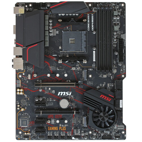
AM4, AMD X570, 4xDDR4-3200 МГц, 2xPCI-Ex16, 2xM.2, Standard-ATX
подробнее

39594,94
Код товара: 1373790