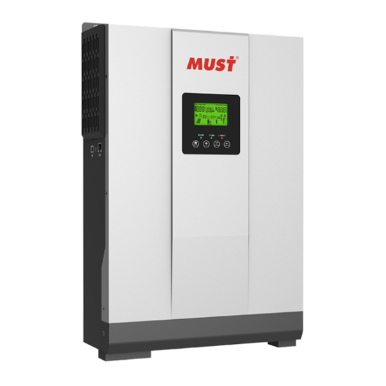
Автономный/Батарейный инвертор MUST PV18-3024 VHM для систем резервного и автономного электроснабжения мощностью 3 кВт и коэффициентом преобразования 1.0, представляет собой многофункциональное устройство, которое сочетает в себе солнечный контроллер заряда, инвертор и зарядное устройство (ЗУ) для зарядки АКБ от сети 220В. Батарейный инвертор MUST PV18-3024 VHM накапливает энергию от солнечных модулей или сети в аккумуляторные батареи. Приоритеты зарядки АКБ и подачи электроэнергии потребителям задаются настройками инвертора. Таким образом, обеспечивается бесперебойная подача электроэнергии к потребителям.
ЖК-дисплей позволяет настраивать пользователю настраивать различные параметры работы, например, ток зарядки аккумулятора, приоритет зарядного устройства переменного / солнечного питания, допустимое входное напряжение, и другое.
Батарейные инверторы MUST PV18-3024 VHM отлично подходят для загородных домов и крупных офисных помещений. Ими можно защищать компьютеры, серверы, котлы отопления. Это недорогие многофункциональные устройства, на которые можно положиться в критической обстановке.
Сферы применения инвертора MUST PV18-3024 VHM:
- солнечные электростанции;
- источники бесперебойного питания;
- источники резервного электропитания;
- другие области применения.
Особенности инвертора MUST PV18-3024 VHM :
- Чистая синусоида на выходе инвертора
- Встроенное слежение за точной максимальной мощности (ТММ) солнечной батареи (MPPT)
- Несколько режимов работы: параллельно с сетью, автономно, параллельно с сетью в режиме резервного источника питания;
- Автоматический перезапуск при востановлении питания переменного тока ;
- Большой жидкокристаллический дисплей отображает всю основную информацию о работе системы солнечного электроснабжения ;
- Возможности для соединения с компьютером для настройки и мониторинга работы системы электроснабжения ;
- Настройка нижнего и верхнего парога зарядки аккумуляторов ;
- Настраиваемый диапазон входного напряжения для домашней техники или ПК ;
- Настраиваемый ток заряда аккумуляторов ;
- 3-х ступенчатый режим заряда АКБ ;
- Защита от перегрузки / перегрева / короткого замыкания ;
- Эффективная конструкция зарядного устройства для оптимизации производительности аккумулятора.
49 thoughts on “Instruction Manual Download”
-
Mouhib hajjar May 13, 2021
Kindly send us a user manual in Arabic
-
Mouhib hajjar May 13, 2021
Kindly send us a user manual in Arabic
-
Which product do you need the Arabic manual?
-
-
HASSANAIN July 6, 2021
I need the upgrade software link for PV3500 , 4k must invertor
-
I need the upgrade software link for PV3500 , 4k must invertor
-
Is This What You Want ?
———— https://en.must-ee.com/archives/24
-
-
hddar al jahour August 22, 2021
PV1800 5248 PRO DOESNT RESTART IT SELF AFTER OVERLOAD … I ENABLED AUTORESTART IN ITS SOFTWARE BUT STILL NO RESTART … IT takes about 30 munite to restart
-
PV1800 5248 PRO DOESNT RESTART IT SELF AFTER OVERLOAD … I ENABLED AUTORESTART IN ITS SOFTWARE BUT STILL NO RESTART … IT takes about 30 munite to restart
-
hello, problem has been reported.
-
-
Martin August 22, 2021
I need manual for model EP 11-2400PRo 24Vdc input inverter. It displays error code 4. What does error code 4 mean?
-
I need manual for model EP 11-2400PRo 24Vdc input inverter. It displays error code 4. What does error code 4 mean?
-
by: https://drive.google.com/file/d/1IP9yKHyYPyq5v86WQ6MY-KW4pDsR94lr/view
-
-
Sam August 30, 2021
Where can I find the documentation of pv1800 VHM holding registers definitions ?
-
Where can I find the documentation of pv1800 VHM holding registers definitions ?
-
Do you mean WIFI description?
-
Tamer Moustafa September 16, 2021
please what is the pass word for the soft ware solar power monitor for PV1800 VPK 3 KW
-
please what is the pass word for the soft ware solar power monitor for PV1800 VPK 3 KW
-
Hi, Tamer
The password is set by yourself, you can also send your wifi device code to your sales to ask for re-set.
Best regards,
MUST
-
-
-
-
what is the password for software SolarPowerMonitor2.2.81 for PV1800VPK 3 KW
-
what is the password for software SolarPowerMonitor2.2.81 for PV1800VPK 3 KW
-
SolarPowerMonitor no password required
-
-
edgardo November 9, 2021
buenos dias saludos como hago para bajar el manual del inversor PV 1800. MD: PV18 3kw vpm
-
buenos dias saludos como hago para bajar el manual del inversor PV 1800. MD: PV18 3kw vpm
-
https://drive.google.com/file/d/1NIE6cWQhSPSJGCtxcDLBdj0HJw6kWx3X/view?usp=sharing
-
-
Ioan November 10, 2021
Where can I find the documentation of pv1800 VHM registers for wifi monitoring?
I have a HF2211 RS485 to wifi device and planning to use it to monitor my solar inverter
Thank you-
Where can I find the documentation of pv1800 VHM registers for wifi monitoring?
I have a HF2211 RS485 to wifi device and planning to use it to monitor my solar inverter
Thank you-
Hi Ioad,
Pls find vedio of WIFI registration in this link.
Best regards,
MUST
-
-
Where can I find the documentation of pv1800 VHM registers for wifi monitoring?
I have a HF2211 RS485 to wifi device and planning to use it to monitor my solar inverter
Thank you-
Where can I find the documentation of pv1800 VHM registers for wifi monitoring?
I have a HF2211 RS485 to wifi device and planning to use it to monitor my solar inverter
Thank you-
https://drive.google.com/file/d/1nd3IZp6st0q4k_n0i7gOYXgTvt_qu8Vc/view?usp=sharing
-
My inverter des not have such a USB input
I would like to use it with the RS-485 output and my 3rd party Modbus-RTU device. I just need to know the inverter address for Modbus TCP protocol.
Thank you-
My inverter des not have such a USB input
I would like to use it with the RS-485 output and my 3rd party Modbus-RTU device. I just need to know the inverter address for Modbus TCP protocol.
Thank you-
This is the inverter I have (without the WIFI RTU module) – https://www.pni.ro/invertor-solar-pni-greenhouse-sc1800b-3kw-24v-60a-mppt-off-grid-hibrid-sinus-pur-cu-modul-wifi-pentru-conectare-internet-inclus.html
-
I will forward the problem to a colleague, please pay attention to your email.
-
enmustee Post authorNovember 17, 2021
I will forward the problem to a colleague, please pay attention to your email.
-
Could you share Modbus RTU registers with me as well? I want to integrate the PV1800 VPK device with Home Assistant software.
-
Hello, we will contact you by email!
-
Hello, we will contact you by email!
-
I would like to have these modbus registers description as well. Working on integration with Home Assistant software.
-
Hi, Sergey
Please check email with WIFI details.
Thanks,
MUST
-
-
-
-
-
enmustee Post authorJanuary 24, 2022
Hi, Sergey
Please check email with WIFI details.
Thanks,
MUST
-
-
-
-
-
Please send me Installation & Operation Manual for PV30-3024MPK Solar Inverter.
Thank you
-
https://drive.google.com/file/d/10puJfjtiMCUWhadVMsp52xoR5m10qiUo/view?usp=sharing
-
-
enmustee Post authorDecember 20, 2021
https://drive.google.com/file/d/10puJfjtiMCUWhadVMsp52xoR5m10qiUo/view?usp=sharing
-
-
Have 2 MUST-PV18-3024-PVK.
They are very bad calibrated and they show Voltage errors off up to 1 volt.
Need Software to calibrate them.
Thanks !-
Hi, Juergen
Please contact your seller to check repair details and parts.
Best regards,
MUST
-
-
Hi, Juergen
Please contact your seller to check repair details and parts.
Best regards,
MUST
-
-
Excuse me, can pictures of the appearance of the machine be provided?
-
Tarek hammoud December 26, 2021
I have pv1800 3kw. Could i get modbus protocol for rs485? To commmunicate hybrid solar inverter with plc. Thanks
-
I have pv1800 3kw. Could i get modbus protocol for rs485? To commmunicate hybrid solar inverter with plc. Thanks
-
Hello, we will contact you by email!
-
Hi, Tarek
Yes sure, pls email to info@mustpower.com
Thank you!
MUST
-
-
-
enmustee Post authorJanuary 24, 2022
Hi, Tarek
Yes sure, pls email to info@mustpower.com
Thank you!
MUST
-
-
-
Good Day Must
Please assist me with the register mapping for the RS485/Can bus registers for the PV-5000.
Thank you very much
Peter Schulze-
Hello, we will contact you by email!
-
-
enmustee Post authorJanuary 24, 2022
Hello, we will contact you by email!
-
-
Please send us a user manual in Turkish for MD:PC18-8015F
-
by: https://drive.google.com/file/d/1_MUhkM6cSF93AVka8p1v369TG8O_t2t5/view?usp=sharing
-
-
enmustee Post authorFebruary 8, 2022
by: https://drive.google.com/file/d/1_MUhkM6cSF93AVka8p1v369TG8O_t2t5/view?usp=sharing
-
-
Plz send manual for ups EH5003 3kva in english
-
https://drive.google.com/file/d/1UYTh_8WsJnQSmHP8SSluzDpduP9xlYf1/view
OR
https://drive.google.com/file/d/1ZbES2TNdItmAz5dO5xdMu4I_WEypozJl/view
-
-
enmustee Post authorFebruary 16, 2022
https://drive.google.com/file/d/1UYTh_8WsJnQSmHP8SSluzDpduP9xlYf1/view
OR
https://drive.google.com/file/d/1ZbES2TNdItmAz5dO5xdMu4I_WEypozJl/view
-
-
The manual’s documents are composed of photo files. I need a document file to understand the product.
I have to use a translator.
Even if it’s important, please prepare a document file and send it to me.
You don’t need a document file composed of pictures.
I have to use a translator.
Don’t you have the original document file?
I don’t understand.
I need the original at least how to set it up.
And what’s the setup mode for charging iron phosphate batteries?-
which model do you need?
-
-
enmustee Post authorMarch 23, 2022
which model do you need?
-
-
Please send me Installation & Operation Manual for PV18-3024VPM and PV18-3024VHM Solar Inverter.
Thank you
-
https://drive.google.com/file/d/1NIE6cWQhSPSJGCtxcDLBdj0HJw6kWx3X/view
https://drive.google.com/file/d/143nbQ-FZmsw5mxHhuvEzrfZUNTYjVCuG/view
-
-
enmustee Post authorMarch 23, 2022
https://drive.google.com/file/d/1NIE6cWQhSPSJGCtxcDLBdj0HJw6kWx3X/view
https://drive.google.com/file/d/143nbQ-FZmsw5mxHhuvEzrfZUNTYjVCuG/view
-
-
i need user manual of pv18-5248 pro
-
hello, link:https://en.must-ee.com/DL/PV1800,3-5.2KW,PRO,EN,MUST,BMS,JC.pdf
-
-
enmustee Post authorSeptember 6, 2022
hello, link:https://en.must-ee.com/DL/PV1800,3-5.2KW,PRO,EN,MUST,BMS,JC.pdf
Yoseph September 18, 2022 I have bought Must Solar Inverter/Charger (with Inbuilt charge controller), 3 kW, 24 Volt, I have 10 universal batteries with 200 AH each (12v). I have issues in selecting the battery type selector . Any help…It will be better if I get a video tutorial installing the inverter/charger set????
-
hello,
https://www.youtube.com/watch?v=cUiXnbnJeBc&list=PLgSOsncQj95XHtVaSdsJa2DyiyOIZK9F-
Leave a Reply
-
Contents
-
Table of Contents
-
Troubleshooting
-
Bookmarks
Quick Links
Related Manuals for Must Power PV18 Series

Summary of Contents for Must Power PV18 Series
-
Page 1
2KW-3KW… -
Page 3: Table Of Contents
Table Of Contents ABOUT THIS MANUAL ………………Purpose ………………….Scope ………………….SAFETY INSTRUCTIONS………………INTRODUCTION………………..Features ………………….Basic System Architecture ……………… Product Overview ………………… INSTALLATION………………..Unpacking and Inspection …………….. Preparation ………………..Mounting the Unit ……………….. Battery Connection ………………. AC Input/Output Connection …………….
-
Page 4: About This Manual
ABOUT THIS MANUAL Purpose This manual describes the assembly, installation, operation and troubleshooting of this unit. Please read this manual carefully before installations and operations. Keep this manual for future reference. Scope This manual provides safety and installation guidelines as well as information on tools and wiring. The following cases are not within the scope of warranty: (1) Out of warranty.
-
Page 5: Introduction
INTRODUCTION This is a multi-function inverter/charger, combining functions of inverter, solar charger and battery charger to offer uninterruptible power support with portable size. Its comprehensive LCD display offers user-congurable and easy-accessible button operation such as battery charging current, AC/solar charger priority, and acceptable input voltage based on different applications. Features Pure sine wave inverter Congurable input voltage range for home appliances and personal computers via LCD setting…
-
Page 6: Product Overview
Product Overview 1. LCD display 2. Status indicator 3. Charging indicator 4. Fault indicator 5. Function buttons 6. Power on/off switch 7. AC input 8. AC output 9. PV input 10. Battery input 11. Circuit breaker 12. RS-485 communication port 13.
-
Page 7: Installation
INSTALLATION Unpacking and Inspection Before installation, please inspect the unit. Be sure that nothing inside the package is damaged. You should have received the following items inside of package: The unit x 1 User manual x 1 Communication cable x 1 USB cable x 1 Software CD X 1 Preparation…
-
Page 8: Battery Connection
Install the unit by screwing three screws. 2~3KW Battery Connection CAUTION: To safety operation and regulation compliance, it’s requested to install a separate DC over-current protector or disconnect device between battery and inverter. It may not be requested to have a disconnect device in some applications, however, it’s still requested to have over-current protection installed.
-
Page 9: Ac Input/Output Connection
3. Insert the ring terminal of battery cable atly into battery connector of inverter and make sure the bolts are tightened with torque of 2-3 Nm. Make sure polarity at both the battery and the inverter/charge is correctly connected and ring terminals are tightly screwed to the battery terminals.
-
Page 10: Pv Connection
→Ground (yellow-green) L→LINE (brown or black) N→Neutral (blue) WARNING: Be sure to that AC power source is disconnected before attempting to hardwire it to the unit. 4. Then, insert AC output wires according to polarities indicated on terminal block and tighten terminal screws.
-
Page 11
Torque Value Typical Amperage Typical Amperage Cable Size 8AWG 1.4~1.6Nm 2KW~3KW 6AWG 2.0~2.4Nm PV Module Selection: When selecting proper PV modules, please be sure to consider below requirements rst: 1. Open circuit Voltage (Voc) of PV modules not exceeds max. PV array open circuit voltage of inverter. 2. -
Page 12: Final Assembly
Solar panel installation schematic MPPT-60A MPPT-80A Final Assembly After connecting all wirings, please put bottom cover back by screwing two screws as shown below.
-
Page 13: Communication Connection
Communication Connection Please use supplied communication cable to connect to inverter and PC. Insert bundled CD into a computer and follow on-screen instruction to install the monitoring software. For the detailed software operation, please check user manual of software inside of CD. WARNING: It’s forbidden to use network cable as the communication cable to directly communicate with the PC port.
-
Page 14: Operation
OPERATION Power ON/OFF Once the unit has been properly installed and the batteries are connected well, simply press On/Off switch (located on the button of the case) to turn on the unit. Operation and Display Panel The operation and display panel, shown in below chart, is on the front panel of the inverter. It includes three indicators, four function keys and a LCD display, indicating the operating status and input/output power information.
-
Page 15: Lcd Display Icons
LCD Display Icons Icon Function description Input Source Information and Output Information Indicates the AC information. Indicates the DC information. Indicate input voltage, input frequency, PV voltage, battery voltage and charger current. Indicate output voltage, output frequency, load in VA, load in Watt and discharging current.
-
Page 16
In battery mode, it will present battery capacity. Load Percentage Battery Voltage LCD Display < 1.717V/cell 1.717V/cell ~ 1.8V/cell Load >50% 1.8 ~ 1.883V/cell > 1.883 V/cell < 1.817V/cell 1.817V/cell ~ 1.9V/cell 50%> Load > 20% 1.9 ~ 1.983V/cell > 1.983V/cell <… -
Page 17: Lcd Setting
LCD Setting After pressing and holding «ENTER» button for 2 seconds, the unit will enter setting mode, and then, press «ENTER» or «MENU» button to conrm the selection and exit. Press «UP» or «DOWN» button to select setting programs. Setting Programs: Program Description Selectable option…
-
Page 18
If selected, acceptable AC input Appliances (default) voltage range will be within 90- 280VAC. If selected, acceptable AC input voltage range will be within AC input voltage range 170-280VAC. If selected, acceptable AC input voltage range will conform to VDE4105(184VAC-253VAC) When the user uses the device to connect the generator, select the generator mode. -
Page 19
Solar and Utility Solar energy and utility will (default) charge battery at the same time. Only Solar Solar energy will be the only charger source no matter utility is available or not. If this inverter/charger is working in Battery mode or Power saving mode, only solar energy can charge battery. -
Page 20
Low DC cut off battery voltage setting If «User-Dened» LI is selected in program 14, this program can be set up. Setting range is from 20.0V to 24.0V for 24Vdc model. Increment of each click is 0.1V. Low DC cut-off voltage will be xed to setting value no matter what percentage of load is connected. -
Page 21: Fault Reference Code
Fault Reference Code Fault Code Fault Event Icon on Fan is locked when inverter is off Inverter transformer over temperature battery voltage is too high battery voltage is too low Output short circuited Inverter output voltage is high Overload time out Inverter bus voltage is too high Bus soft start failed Main relay failed…
-
Page 22: Warning Indicator
Inverter grid under frequency Inverter grid over frequency Inverter over current protection error Inverter bus voltage is too low Inverter soft start failed Over DC voltage in AC output Battery connection is open Inverter control current sensor error Inverter output voltage is too low Warning Indicator Icon on Fault Code…
-
Page 23: Operating Mode Description
Operating State Description Operation state Description LCD display PV is on PV energy is charger Utility-Tie state into the battery and utility provide power to the AC load. PV is off Charge state PV energy and grid can charge batteries. Bypass state Error are caused by inside circuit error or…
-
Page 24: Display Setting
Display Setting The LCD display information will be switched in turns by pressing «UP» or «DOWN» key. The selectable information is switched as below order: battery voltage, battery current ,inverter voltage, inverter current, grid voltage, grid current, load in Watt, load in VA, grid frequency, inverter frequency, PV voltage, PV charging power, PV charging output voltage, PV charging current.
-
Page 25: Specifications
SPECIFICATIONS Table 1 Line Mode Specications INVERTER MODEL Input Voltage Waveform Sinusoidal (utility or generator) Nominal Input Voltage 230Vac 90Vac±7V(APL,GEN); 170Vac±7V(UPS) Low Loss Voltage 186Vac±7V(VDE) 100Vac±7V(APL,GEN);180Vac±7V(UPS) Low Loss Return Voltage 196Vac±7V(VDE) 280Vac±7V(APL, UPS,GEN) High Loss Voltage 253Vac±7V(VDE) 270Vac±7V(APL,UPS,GEN) High Loss Return Voltage 250Vac±7V(VDE) Max AC Input Voltage 300Vac…
-
Page 26: Table 2 Inverter Mode SpeciCations
Table 2 Inverter Mode Specications INVERTER MODEL Rated Output Power 2KW/2000W 3KW/3000W Output Voltage Waveform Pure Sine Wave Output Voltage Regulation 230Vac±5% Output Frequency 60Hz or 50Hz Peak Efciency 5s@≥150% load; 10s@110%~150% load Overload Protection Nominal DC Input Voltage 24Vdc Cold Start Voltage 23.0Vdc Low DC Warning Voltage…
-
Page 27: Table 3 Charge Mode SpeciCations
Table 3 Charge Mode Specications Utility Charging Mode INVERTER MODEL Charging Current 20/30A @Nominal Input Voltage AGM / Gel/LEAD 25Vdc Absorption Battery Voltage Flooded Battery 25Vdc AGM / Gel/LEAD 27.4Vdc Reoat Battery Voltage Flooded Battery 27.4Vdc AGM / Gel/LEAD 28.8Vdc Float Battery Voltage…
-
Page 28: Table 4 General SpeciCations
Charging algorithm for Lithium battery Joint Utility and Solar Charging 2KW/3KW INVERTER MODEL MPPT-60A MPPT-80A CHARGER MODEL Max Charging Current Default Charging Current Table 4 General Specications INVERTER MODEL Safety Certication Operating Temperature Range 0°C to 50°C Storage temperature -15°C~ 60°C Dimension (D*W*H), mm 290 x 396 x 108 Net Weight, kg…
-
Page 29: Trouble Shooting
TROUBLE SHOOTING Explanation/Possible cause What to do LCD/LED/Buzzer Problem Unit shuts down LCD/LEDs and buzzer automatically will be active for 3 The battery voltage is too low. 1. Re-charge battery. during startup seconds and then (<1.91V/Cell) 2. Replace battery. process. complete off.
-
Page 30: Appendix: Approximate Back-Up Time Table
Appendix: Approximate Back-up Time Table Load (W) Backup Time @ 24Vdc 100Ah (min) Backup Time @ 24Vdc 200Ah (min) Model 1610 1000 1200 1400 1600 1800 2000 1100 1200 1500 1800 2100 2400 2700 3000 Note: Backup time depends on the quality of the battery, age of battery and type of battery. Specications of batteries may vary depending on different manufacturers.
-
Page 32
SOLAR INVERTER/CHARGER 420-00343-00…
Обновление серии PV18 HM. У инверторов VHM мощность в Вт равна мощности в ВА.
Инверторы серии Combi-M PV1800 VHM созданы специально для работы в составе солнечных систем. В производимой линейке представлены устройства мощностью от 1 кВА (12В) до 5 кВА (48В). В нашем ассортименте обычно модели на 3 кВт 24В и 5 кВт 48В.
Инвертор, кроме сетевого зарядного устройства, имеет мощный солнечный MPPT контроллер на ток 60/80А, что позволяет синхронизировать работу электросети и солнечных батарей. Иными словами, инвертор способен передавать потребителям сетевую и «солнечную» энергию в зависимости от выбранных пользователем приоритетов. Устройства выполнены по высокочастотной схеме и обладают высоким КПД, что, в совокупности с низким собственным потреблением, делает их крайне эффективными при работе в составе автономных солнечных электростанций. Мощность сетевого зарядного устройства довольно велика, практически равняется мощности самого инвертора, например, у модели 4 кВA, максимальный зарядный ток 60А (48В). Таким образом, при заряде аккумуляторов от генератора, обеспечивается минимальное время заряда и режим экономии топлива.
Инверторы все серии PV 1800 обеспечивают также:
- Синусоидальный выходной сигнал;
- Возможность выбора диапазона входного напряжения;
- Возможность выбора величины зарядного тока. Данная функция бывает очень полезна при работе с аккумуляторами малой емкости;
- Возможность выбора приоритетного источника энергии для питания нагрузки (солнечные батареи-сеть-аккумуляторы);
- Защиту от перегрузки и короткого замыкания, глубокого разряда АКБ;
- информативный ЖК-дисплей;
- автоматический перезапуск в случае сработки защиты или возобновления питания от сети;
- функция холодного старта
- встроенное солнечное зарядное устройство со слежением за точкой максимальной мощности солнечной батареи (МРРТ).
Особенности инвертора Combi-M PV1800 3024 VHM
Combi-M PV18 3024 VHM — это однофазный блок бесперебойного питания (инвертор с зарядным устройством), расчитанный на эксплуатацию с нагрузкой номинальной мощностью до 3 кВт / 3 кВА. ББП содержит солнечный MPPT контроллер, который может отслеживать точку максимально мощности солнечной батареи. Комбинированный инвертор широко используется для систем автономного, резервного или бесперебойного электропитания для дач, квартир, небольших домов и офисов, или даже компьютерной техники, серверов и котлов. И вам для этого достаточно всего одного устройства!
Технические характеристики:
| Тип инвертора | комбинированный батарейный |
| Количество фаз | 1 |
| Номинальная мощность нагрузки, Вт (ВА) | 3000 (3000) |
| Кратковременная перегрузка, Вт (ВА) | 6000 |
| Допустимые перегрузки /в течении | 150% / 5 с |
| Форма выходного напряжения | Чистая синусоида |
| Номинальное напряжение переменного тока, В | 230 |
| Номинальная частота входной сети, Гц | 50 / 60 (автоопределение) |
| Диапазон входных напряжений | 90…280В (режим APL) / 170…280В (режим UPS) / 186…253В режим VDE4105) |
| Номинальное напряжение АБ, В | 24 |
| Зарядный ток АБ, А | 20…80 (устанавливается в меню, суммируются токи ЗУ от сети и от солнечного контроллера) |
| Максимальный ток заряда от солнечных батарей, А | 60 (устанавливается с шагом 1 А) |
| Максимальный ток заряда от сети, А | 20 или 30 |
| Алгоритм заряда АБ | 3-х ступенчатый (основной заряд, поглощающий заряд [absorption], поддерживающий заряд) для GEL/AGM/Flooded / 4-х ступечатый для Li |
| Рекомендуемая ёмкость АБ, А*ч | 100…900 |
| Тип солнечного контроллера | MPPT |
| Максимальное напряжение холостого хода СБ, В | 145 |
| Диапазон слежения за ТММ, В | 30-130 |
| Время переключения на АБ, мс | 10…20 |
| Собственное потребление инвертора на холостом ходу | не более 25 Вт |
| Собственное потребление солнечного контроллера | 2 Вт |
| Количество MPPT трекеров | 1 |
| Макс. входная мощность СБ, Вт | 1920 |
| Эффективность MPPT | 98% |
| КПД инвертора | 93% |
| Степень защиты | IP20 |
| Допустимая влажность | 0…80% (без образования конденсата) |
| Размеры (ш/в/г), мм | 272/355/100 |
| Размеры упаковки (д/ш/в), мм | 540/395/241 |
| Вес, кг | 11,0 /11,7 |
| Гарантия, мес | 12 |
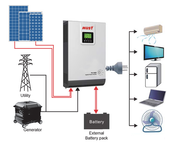 Для полноценной работы к инвертору необходимо подключить АКБ, солнечные батареи, входную электрическую сеть и нагрузку. ББП оснащён двумя зарядными устройствами — от солнечных батарей с одним MPPT-трекером и от входящей электрической сети. Инвертор оснащён ЖК-индикатором, который отображает схематически текущий рабочий режим и позволяет ознакомится с рабочими параметрами (напряжения и токи). Для ознакомления с рабочими параметрами и настройки рабочей конфигурации инвертора используются 4 функциональные кнопки. Режимы зарядки и приоритеты работы легко настраиваются инсталлятором или самим пользователем.
Пользователь или инсталлятор может выбирать и изменять следующие приоритеты работы и настройки:
— приоритетный источник питания нагрузки;
— приоритетный источник для зарядки АКБ;
— тип используемых АКБ и параметры их зарядки.
Подробнее о приоритетах:
- Источник питания нагрузки. Пользователю предлагается определится какое значение в системе питания он отводит гибридному инвертору — резервное питание от входной сети 220В или максимальная автономия и снижение зависимости от входной электрической сети и получение максимального количества энергии от Солнца. В случае резервного питания пользователь выбирает режим, при котором инвертор в первую очередь подключает нагрузку напрямую к электрической сети, а при её пропадании переходит на питание от солнечных батарей днём или АКБ вечером и ночью до момента разряда АКБ или восстановления входной сети. В случае выбора режима максимальной автономии инвертор сначала питает нагрузку от энергии Солнца, затем переходит на питание от АКБ и если АКБ разряжен, а Солнце ещё не даёт энергии, то переходит на питание от внешней сети и при возобновлении выработки энергии от Солнца после заряда АКБ возобновляет питание от энергии Солнца.
- Источник для заряда АКБ. Пользователю доступны три режима заряда АКБ — только от солнечной энергии, от солнечной энергии и при её отсутствии от входной сети, от входной сети и при её отсутствии от солнечной энергии.
- Тип используемых АКБ и параметры зарядки. Пользователю доступен выбор типа АКБ — AGM, Flooded, User defined. Для типа AGM (или GEL) параметры заряда установлены на заводе, в иных режимах пользователь сам подбирает величины напряжений для режимов заряда bulk, floating, порога разряда и порога достаточной степени заряда для подачи солнечной энергии для питания нагрузки. Также пользователь выбирает величину максимального тока заряда АКБ — 20А или 30А.
Также пользователь может выбрать частоту выходного переменного напряжения 50Гц или 60Гц, диапазон напряжений входной сети, пропускаемого без коррекции — или 90…280В, или 170…280В, режим авторестарта после срабатывания защиты, звуковой сигнализации отсутствия основного источника питания.
Для мониторинга работы инвертора он может быть подключен к компьютеру через COM-порт и с помощью ПО из комплекта поставки выдавать рабочую информацию на ПК.
Рекомендации по размещению инвертора — располагать на вертикальной стене, минимальный отступ сверху и снизу от препятствий — 300мм, от боковых препятствий — 200мм. Это необходимо для обеспечения эффективного воздушного охлаждения инвертора.
Рекомендации по подключению кабелей к инвертору — в первую очередь подключите заземление! Во вторую очередь подключите АКБ и затем уже входную сеть и нагрузку! Сечение подключаемых проводов не должно быть меньше 2.5 мм² для 220В, не меньше 16 мм² для АКБ. Сечение провода для солнечных батарей рассчитывается по допустимому падению напряжения, и обычно не менее 4 мм².
Комплект поставки
- Блок бесперебойного питания
- Инструкция
- Кабель USB-USB для соединения с компьютером
- CD c программным обеспечением для компьютера (не поставляется с 2021 года, ПО можно скачать по ссылке)
Сертификация — инвертор сертифицирован для продажи в ЕС (сертификация CE), обязательной сертификации в России не подлежит.
Гарантия от производителя — 1 год.
Скачать инструкцию на русском языке
перейти к содержанию
hello,![]() enmustee Post authorSeptember 21, 2022
enmustee Post authorSeptember 21, 2022
https://www.youtube.com/watch?v=cUiXnbnJeBc&list=PLgSOsncQj95XHtVaSdsJa2DyiyOIZK9F-
Leave a Reply
-
Contents
-
Table of Contents
-
Troubleshooting
-
Bookmarks
Quick Links
Related Manuals for Must Power PV18 Series
Summary of Contents for Must Power PV18 Series
-
Page 1
2KW-3KW… -
Page 3: Table Of Contents
Table Of Contents ABOUT THIS MANUAL ………………Purpose ………………….Scope ………………….SAFETY INSTRUCTIONS………………INTRODUCTION………………..Features ………………….Basic System Architecture ……………… Product Overview ………………… INSTALLATION………………..Unpacking and Inspection …………….. Preparation ………………..Mounting the Unit ……………….. Battery Connection ………………. AC Input/Output Connection …………….
-
Page 4: About This Manual
ABOUT THIS MANUAL Purpose This manual describes the assembly, installation, operation and troubleshooting of this unit. Please read this manual carefully before installations and operations. Keep this manual for future reference. Scope This manual provides safety and installation guidelines as well as information on tools and wiring. The following cases are not within the scope of warranty: (1) Out of warranty.
-
Page 5: Introduction
INTRODUCTION This is a multi-function inverter/charger, combining functions of inverter, solar charger and battery charger to offer uninterruptible power support with portable size. Its comprehensive LCD display offers user-congurable and easy-accessible button operation such as battery charging current, AC/solar charger priority, and acceptable input voltage based on different applications. Features Pure sine wave inverter Congurable input voltage range for home appliances and personal computers via LCD setting…
-
Page 6: Product Overview
Product Overview 1. LCD display 2. Status indicator 3. Charging indicator 4. Fault indicator 5. Function buttons 6. Power on/off switch 7. AC input 8. AC output 9. PV input 10. Battery input 11. Circuit breaker 12. RS-485 communication port 13.
-
Page 7: Installation
INSTALLATION Unpacking and Inspection Before installation, please inspect the unit. Be sure that nothing inside the package is damaged. You should have received the following items inside of package: The unit x 1 User manual x 1 Communication cable x 1 USB cable x 1 Software CD X 1 Preparation…
-
Page 8: Battery Connection
Install the unit by screwing three screws. 2~3KW Battery Connection CAUTION: To safety operation and regulation compliance, it’s requested to install a separate DC over-current protector or disconnect device between battery and inverter. It may not be requested to have a disconnect device in some applications, however, it’s still requested to have over-current protection installed.
-
Page 9: Ac Input/Output Connection
3. Insert the ring terminal of battery cable atly into battery connector of inverter and make sure the bolts are tightened with torque of 2-3 Nm. Make sure polarity at both the battery and the inverter/charge is correctly connected and ring terminals are tightly screwed to the battery terminals.
-
Page 10: Pv Connection
→Ground (yellow-green) L→LINE (brown or black) N→Neutral (blue) WARNING: Be sure to that AC power source is disconnected before attempting to hardwire it to the unit. 4. Then, insert AC output wires according to polarities indicated on terminal block and tighten terminal screws.
-
Page 11
Torque Value Typical Amperage Typical Amperage Cable Size 8AWG 1.4~1.6Nm 2KW~3KW 6AWG 2.0~2.4Nm PV Module Selection: When selecting proper PV modules, please be sure to consider below requirements rst: 1. Open circuit Voltage (Voc) of PV modules not exceeds max. PV array open circuit voltage of inverter. 2. -
Page 12: Final Assembly
Solar panel installation schematic MPPT-60A MPPT-80A Final Assembly After connecting all wirings, please put bottom cover back by screwing two screws as shown below.
-
Page 13: Communication Connection
Communication Connection Please use supplied communication cable to connect to inverter and PC. Insert bundled CD into a computer and follow on-screen instruction to install the monitoring software. For the detailed software operation, please check user manual of software inside of CD. WARNING: It’s forbidden to use network cable as the communication cable to directly communicate with the PC port.
-
Page 14: Operation
OPERATION Power ON/OFF Once the unit has been properly installed and the batteries are connected well, simply press On/Off switch (located on the button of the case) to turn on the unit. Operation and Display Panel The operation and display panel, shown in below chart, is on the front panel of the inverter. It includes three indicators, four function keys and a LCD display, indicating the operating status and input/output power information.
-
Page 15: Lcd Display Icons
LCD Display Icons Icon Function description Input Source Information and Output Information Indicates the AC information. Indicates the DC information. Indicate input voltage, input frequency, PV voltage, battery voltage and charger current. Indicate output voltage, output frequency, load in VA, load in Watt and discharging current.
-
Page 16
In battery mode, it will present battery capacity. Load Percentage Battery Voltage LCD Display < 1.717V/cell 1.717V/cell ~ 1.8V/cell Load >50% 1.8 ~ 1.883V/cell > 1.883 V/cell < 1.817V/cell 1.817V/cell ~ 1.9V/cell 50%> Load > 20% 1.9 ~ 1.983V/cell > 1.983V/cell <… -
Page 17: Lcd Setting
LCD Setting After pressing and holding «ENTER» button for 2 seconds, the unit will enter setting mode, and then, press «ENTER» or «MENU» button to conrm the selection and exit. Press «UP» or «DOWN» button to select setting programs. Setting Programs: Program Description Selectable option…
-
Page 18
If selected, acceptable AC input Appliances (default) voltage range will be within 90- 280VAC. If selected, acceptable AC input voltage range will be within AC input voltage range 170-280VAC. If selected, acceptable AC input voltage range will conform to VDE4105(184VAC-253VAC) When the user uses the device to connect the generator, select the generator mode. -
Page 19
Solar and Utility Solar energy and utility will (default) charge battery at the same time. Only Solar Solar energy will be the only charger source no matter utility is available or not. If this inverter/charger is working in Battery mode or Power saving mode, only solar energy can charge battery. -
Page 20
Low DC cut off battery voltage setting If «User-Dened» LI is selected in program 14, this program can be set up. Setting range is from 20.0V to 24.0V for 24Vdc model. Increment of each click is 0.1V. Low DC cut-off voltage will be xed to setting value no matter what percentage of load is connected. -
Page 21: Fault Reference Code
Fault Reference Code Fault Code Fault Event Icon on Fan is locked when inverter is off Inverter transformer over temperature battery voltage is too high battery voltage is too low Output short circuited Inverter output voltage is high Overload time out Inverter bus voltage is too high Bus soft start failed Main relay failed…
-
Page 22: Warning Indicator
Inverter grid under frequency Inverter grid over frequency Inverter over current protection error Inverter bus voltage is too low Inverter soft start failed Over DC voltage in AC output Battery connection is open Inverter control current sensor error Inverter output voltage is too low Warning Indicator Icon on Fault Code…
-
Page 23: Operating Mode Description
Operating State Description Operation state Description LCD display PV is on PV energy is charger Utility-Tie state into the battery and utility provide power to the AC load. PV is off Charge state PV energy and grid can charge batteries. Bypass state Error are caused by inside circuit error or…
-
Page 24: Display Setting
Display Setting The LCD display information will be switched in turns by pressing «UP» or «DOWN» key. The selectable information is switched as below order: battery voltage, battery current ,inverter voltage, inverter current, grid voltage, grid current, load in Watt, load in VA, grid frequency, inverter frequency, PV voltage, PV charging power, PV charging output voltage, PV charging current.
-
Page 25: Specifications
SPECIFICATIONS Table 1 Line Mode Specications INVERTER MODEL Input Voltage Waveform Sinusoidal (utility or generator) Nominal Input Voltage 230Vac 90Vac±7V(APL,GEN); 170Vac±7V(UPS) Low Loss Voltage 186Vac±7V(VDE) 100Vac±7V(APL,GEN);180Vac±7V(UPS) Low Loss Return Voltage 196Vac±7V(VDE) 280Vac±7V(APL, UPS,GEN) High Loss Voltage 253Vac±7V(VDE) 270Vac±7V(APL,UPS,GEN) High Loss Return Voltage 250Vac±7V(VDE) Max AC Input Voltage 300Vac…
-
Page 26: Table 2 Inverter Mode SpeciCations
Table 2 Inverter Mode Specications INVERTER MODEL Rated Output Power 2KW/2000W 3KW/3000W Output Voltage Waveform Pure Sine Wave Output Voltage Regulation 230Vac±5% Output Frequency 60Hz or 50Hz Peak Efciency 5s@≥150% load; 10s@110%~150% load Overload Protection Nominal DC Input Voltage 24Vdc Cold Start Voltage 23.0Vdc Low DC Warning Voltage…
-
Page 27: Table 3 Charge Mode SpeciCations
Table 3 Charge Mode Specications Utility Charging Mode INVERTER MODEL Charging Current 20/30A @Nominal Input Voltage AGM / Gel/LEAD 25Vdc Absorption Battery Voltage Flooded Battery 25Vdc AGM / Gel/LEAD 27.4Vdc Reoat Battery Voltage Flooded Battery 27.4Vdc AGM / Gel/LEAD 28.8Vdc Float Battery Voltage…
-
Page 28: Table 4 General SpeciCations
Charging algorithm for Lithium battery Joint Utility and Solar Charging 2KW/3KW INVERTER MODEL MPPT-60A MPPT-80A CHARGER MODEL Max Charging Current Default Charging Current Table 4 General Specications INVERTER MODEL Safety Certication Operating Temperature Range 0°C to 50°C Storage temperature -15°C~ 60°C Dimension (D*W*H), mm 290 x 396 x 108 Net Weight, kg…
-
Page 29: Trouble Shooting
TROUBLE SHOOTING Explanation/Possible cause What to do LCD/LED/Buzzer Problem Unit shuts down LCD/LEDs and buzzer automatically will be active for 3 The battery voltage is too low. 1. Re-charge battery. during startup seconds and then (<1.91V/Cell) 2. Replace battery. process. complete off.
-
Page 30: Appendix: Approximate Back-Up Time Table
Appendix: Approximate Back-up Time Table Load (W) Backup Time @ 24Vdc 100Ah (min) Backup Time @ 24Vdc 200Ah (min) Model 1610 1000 1200 1400 1600 1800 2000 1100 1200 1500 1800 2100 2400 2700 3000 Note: Backup time depends on the quality of the battery, age of battery and type of battery. Specications of batteries may vary depending on different manufacturers.
-
Page 32
SOLAR INVERTER/CHARGER 420-00343-00…
Обновление серии PV18 HM. У инверторов VHM мощность в Вт равна мощности в ВА.
Инверторы серии Combi-M PV1800 VHM созданы специально для работы в составе солнечных систем. В производимой линейке представлены устройства мощностью от 1 кВА (12В) до 5 кВА (48В). В нашем ассортименте обычно модели на 3 кВт 24В и 5 кВт 48В.
Инвертор, кроме сетевого зарядного устройства, имеет мощный солнечный MPPT контроллер на ток 60/80А, что позволяет синхронизировать работу электросети и солнечных батарей. Иными словами, инвертор способен передавать потребителям сетевую и «солнечную» энергию в зависимости от выбранных пользователем приоритетов. Устройства выполнены по высокочастотной схеме и обладают высоким КПД, что, в совокупности с низким собственным потреблением, делает их крайне эффективными при работе в составе автономных солнечных электростанций. Мощность сетевого зарядного устройства довольно велика, практически равняется мощности самого инвертора, например, у модели 4 кВA, максимальный зарядный ток 60А (48В). Таким образом, при заряде аккумуляторов от генератора, обеспечивается минимальное время заряда и режим экономии топлива.
Инверторы все серии PV 1800 обеспечивают также:
- Синусоидальный выходной сигнал;
- Возможность выбора диапазона входного напряжения;
- Возможность выбора величины зарядного тока. Данная функция бывает очень полезна при работе с аккумуляторами малой емкости;
- Возможность выбора приоритетного источника энергии для питания нагрузки (солнечные батареи-сеть-аккумуляторы);
- Защиту от перегрузки и короткого замыкания, глубокого разряда АКБ;
- информативный ЖК-дисплей;
- автоматический перезапуск в случае сработки защиты или возобновления питания от сети;
- функция холодного старта
- встроенное солнечное зарядное устройство со слежением за точкой максимальной мощности солнечной батареи (МРРТ).
Особенности инвертора Combi-M PV1800 3024 VHM
Combi-M PV18 3024 VHM — это однофазный блок бесперебойного питания (инвертор с зарядным устройством), расчитанный на эксплуатацию с нагрузкой номинальной мощностью до 3 кВт / 3 кВА. ББП содержит солнечный MPPT контроллер, который может отслеживать точку максимально мощности солнечной батареи. Комбинированный инвертор широко используется для систем автономного, резервного или бесперебойного электропитания для дач, квартир, небольших домов и офисов, или даже компьютерной техники, серверов и котлов. И вам для этого достаточно всего одного устройства!
Технические характеристики:
| Тип инвертора | комбинированный батарейный |
| Количество фаз | 1 |
| Номинальная мощность нагрузки, Вт (ВА) | 3000 (3000) |
| Кратковременная перегрузка, Вт (ВА) | 6000 |
| Допустимые перегрузки /в течении | 150% / 5 с |
| Форма выходного напряжения | Чистая синусоида |
| Номинальное напряжение переменного тока, В | 230 |
| Номинальная частота входной сети, Гц | 50 / 60 (автоопределение) |
| Диапазон входных напряжений | 90…280В (режим APL) / 170…280В (режим UPS) / 186…253В режим VDE4105) |
| Номинальное напряжение АБ, В | 24 |
| Зарядный ток АБ, А | 20…80 (устанавливается в меню, суммируются токи ЗУ от сети и от солнечного контроллера) |
| Максимальный ток заряда от солнечных батарей, А | 60 (устанавливается с шагом 1 А) |
| Максимальный ток заряда от сети, А | 20 или 30 |
| Алгоритм заряда АБ | 3-х ступенчатый (основной заряд, поглощающий заряд [absorption], поддерживающий заряд) для GEL/AGM/Flooded / 4-х ступечатый для Li |
| Рекомендуемая ёмкость АБ, А*ч | 100…900 |
| Тип солнечного контроллера | MPPT |
| Максимальное напряжение холостого хода СБ, В | 145 |
| Диапазон слежения за ТММ, В | 30-130 |
| Время переключения на АБ, мс | 10…20 |
| Собственное потребление инвертора на холостом ходу | не более 25 Вт |
| Собственное потребление солнечного контроллера | 2 Вт |
| Количество MPPT трекеров | 1 |
| Макс. входная мощность СБ, Вт | 1920 |
| Эффективность MPPT | 98% |
| КПД инвертора | 93% |
| Степень защиты | IP20 |
| Допустимая влажность | 0…80% (без образования конденсата) |
| Размеры (ш/в/г), мм | 272/355/100 |
| Размеры упаковки (д/ш/в), мм | 540/395/241 |
| Вес, кг | 11,0 /11,7 |
| Гарантия, мес | 12 |
Для полноценной работы к инвертору необходимо подключить АКБ, солнечные батареи, входную электрическую сеть и нагрузку. ББП оснащён двумя зарядными устройствами — от солнечных батарей с одним MPPT-трекером и от входящей электрической сети. Инвертор оснащён ЖК-индикатором, который отображает схематически текущий рабочий режим и позволяет ознакомится с рабочими параметрами (напряжения и токи). Для ознакомления с рабочими параметрами и настройки рабочей конфигурации инвертора используются 4 функциональные кнопки. Режимы зарядки и приоритеты работы легко настраиваются инсталлятором или самим пользователем.
Пользователь или инсталлятор может выбирать и изменять следующие приоритеты работы и настройки:
— приоритетный источник питания нагрузки;
— приоритетный источник для зарядки АКБ;
— тип используемых АКБ и параметры их зарядки.
Подробнее о приоритетах:
- Источник питания нагрузки. Пользователю предлагается определится какое значение в системе питания он отводит гибридному инвертору — резервное питание от входной сети 220В или максимальная автономия и снижение зависимости от входной электрической сети и получение максимального количества энергии от Солнца. В случае резервного питания пользователь выбирает режим, при котором инвертор в первую очередь подключает нагрузку напрямую к электрической сети, а при её пропадании переходит на питание от солнечных батарей днём или АКБ вечером и ночью до момента разряда АКБ или восстановления входной сети. В случае выбора режима максимальной автономии инвертор сначала питает нагрузку от энергии Солнца, затем переходит на питание от АКБ и если АКБ разряжен, а Солнце ещё не даёт энергии, то переходит на питание от внешней сети и при возобновлении выработки энергии от Солнца после заряда АКБ возобновляет питание от энергии Солнца.
- Источник для заряда АКБ. Пользователю доступны три режима заряда АКБ — только от солнечной энергии, от солнечной энергии и при её отсутствии от входной сети, от входной сети и при её отсутствии от солнечной энергии.
- Тип используемых АКБ и параметры зарядки. Пользователю доступен выбор типа АКБ — AGM, Flooded, User defined. Для типа AGM (или GEL) параметры заряда установлены на заводе, в иных режимах пользователь сам подбирает величины напряжений для режимов заряда bulk, floating, порога разряда и порога достаточной степени заряда для подачи солнечной энергии для питания нагрузки. Также пользователь выбирает величину максимального тока заряда АКБ — 20А или 30А.
Также пользователь может выбрать частоту выходного переменного напряжения 50Гц или 60Гц, диапазон напряжений входной сети, пропускаемого без коррекции — или 90…280В, или 170…280В, режим авторестарта после срабатывания защиты, звуковой сигнализации отсутствия основного источника питания.
Для мониторинга работы инвертора он может быть подключен к компьютеру через COM-порт и с помощью ПО из комплекта поставки выдавать рабочую информацию на ПК.
Рекомендации по размещению инвертора — располагать на вертикальной стене, минимальный отступ сверху и снизу от препятствий — 300мм, от боковых препятствий — 200мм. Это необходимо для обеспечения эффективного воздушного охлаждения инвертора.
Рекомендации по подключению кабелей к инвертору — в первую очередь подключите заземление! Во вторую очередь подключите АКБ и затем уже входную сеть и нагрузку! Сечение подключаемых проводов не должно быть меньше 2.5 мм² для 220В, не меньше 16 мм² для АКБ. Сечение провода для солнечных батарей рассчитывается по допустимому падению напряжения, и обычно не менее 4 мм².
Комплект поставки
- Блок бесперебойного питания
- Инструкция
- Кабель USB-USB для соединения с компьютером
- CD c программным обеспечением для компьютера (не поставляется с 2021 года, ПО можно скачать по ссылке)
Сертификация — инвертор сертифицирован для продажи в ЕС (сертификация CE), обязательной сертификации в России не подлежит.
Гарантия от производителя — 1 год.
Скачать инструкцию на русском языке
перейти к содержанию
![]() Высокочастотный автономный солнечный инвертор серии PV1800 VHM
Высокочастотный автономный солнечный инвертор серии PV1800 VHM
Руководство пользователя
 Особенности
- Номинальная мощность: 2кВт-5.5кВт
- Чистый синусоидальный солнечный инвертор
- Коэффициент выходной мощности 1
- Встроенное солнечное зарядное устройство MPPT на 80 А.
- Встроенный комплект для защиты от пыли для суровых условий
- Поддержка параллельной работы до 3 устройств (доступно для 3 кВт-5.5 кВт 48 В)
- Удаленный мониторинг WIFI (опционально)
- Совместимость с генератором
Введение
PV1800 VHM — это многофункциональный инвертор/зарядное устройство, сочетающий в себе функции инвертора, солнечного зарядного устройства и зарядного устройства для аккумуляторов, обеспечивающий бесперебойную работу в портативном размере. Его всеобъемлющий ЖК-дисплей предлагает настраиваемую пользователем и легкодоступную кнопочную операцию, такую как ток зарядки аккумулятора, приоритет зарядного устройства переменного тока / солнечной батареи и приемлемую входную громкость.tage на основе различных приложений.
Описание печати на задней панели
- ЖК дисплей
- Индикатор состояния
- Индикатор зарядки
- Индикатор неисправности
- Кнопки функций

- вход переменного тока
- Выход переменного тока
- Выключатель
- Вход батареи
- PV вход
- Выключатель питания вкл / выкл
- Порт связи RS-485
- USB
- Сухой контакт
- usb-wi-fi
- Параллельный переключатель
- Параллельный коммуникационный порт (только для параллельной модели)
Подключение солнечной системы

Спецификация
| МОДЕЛЬ | ПВ18-2024 ОБМ |
ПВ18-3024 ОБМ |
ПВ18-3048 ОБМ |
ПВ18-4048 ОБМ |
ПВ18-5048 ОБМ |
ПВ18-5548 ОБМ |
|
| Номинальный объем аккумуляторной системыtage | 2IVDC | ||||||
| Инвертор ВЫВОД |
Номинальная мощность | 2000W | 3000W | 3000W | 4000W | 5000W | 5500W |
| Всплеск мощности | 4000W | 6000W | 6000W | 8000W | 10000W | 11000W | |
| Waveform | Чистая синусоида | ||||||
| том переменного токаtage Регулирование (BattMode) | (220В~-240В~)±5% | ||||||
| Эффективность инвертора (пиковая) | 93% | ||||||
| Время передачи | тома (ИБП и VDE4105) 20 мс (APL) | ||||||
| AC INPUT | Voltage | 230VAC | |||||
| Выбираемый объемtage Диапазон | 170-280VAC(UPS)/ 90-280VAC(APL) i 184-253VAC(VDE4105) | ||||||
| Диапазон частот | 50 Гц / 60 Гц (автоматическое определение) | ||||||
| БАТАРЕИ | Нормальная громкостьtage | 2IVDC | 48 DC | ||||
| Плавающий объем зарядаtage | 27.ИВДК | 51.8 DC | |||||
| Защита от перезарядки | 30 DC | 60 DC | |||||
| СОЛНЕЧНОЕ ЗАРЯДНОЕ УСТРОЙСТВО И ЗАРЯДНОЕ УСТРОЙСТВО ПЕРЕМЕННОГО ТОКА | Максимальный PV Amy Open Circuit vdtage | 145 DC | |||||
| PV массив MPPT Voltage Диапазон | 30-130VDC | 60-130VDC | |||||
| Энергопотребление в режиме ожидания | 2W | ||||||
| Входная мощность фотоэлектрических модулей | 2000W | 4000W | |||||
| Максимальный ток солнечного заряда | 80A | ||||||
| Максимальная эффективность | 98% | ||||||
| Максимальный ток зарядки переменного тока | 201 / 33A | 60A | |||||
| Максимальный ток зарядки | 80A | 140A | |||||
| МЕХАНИЧЕСКИЕ ХАРАКТЕРИСТИКИ |
Размеры машины (N•H•DXмм) | 300’4141’116 | 329’485’134 | ||||
| Размер упаковки (WH’D) (ммл | 123’599’257 | 426.5’507’250 | |||||
| Вес неттоgre) | 10 | 11 | 12 | ||||
| Вес брутто (кг) | 12 | 12 | 14 | ||||
| ДРУГИЕ | Влажность | 5% 095% Ftelaby Hurnidtty (без конденсации) | |||||
| Рабочая Температура | 0°С-50°С | ||||||
| Температура хранения | -15°С -60°С |
Технические характеристики этого документа могут быть изменены без предварительного уведомления.![]()
Документы / Ресурсы