Стоматологическая клиника Barenjungplant, Пусан, Южная Корея
Введение
Установка имплантатов в оптимальном положении всегда играла ключевую роль. Компьютерная томография (КТ) области имплантации с применением рентгенологических шаблонов с рентгеноконтрастными маркерами позволяет наметить оптимальное положение имплантата и наклон его оси до проведения операции. Хирургический шаблон обеспечивает правильное позиционирования имплантатов. Его можно также использовать и при проведении рентгенологического исследования во время операции или на этапе планирования лечения.
Целью настоящего исследования является оценка эффективности компьютерного планирования лечения и хирургических шаблонов OneGuide.
Отчет о клиническом случае
Двум пациентам с частичной адентией планировали установить имплантаты с помощью хирургических шаблонов OneGuide. Данные компьютерной томографии импортировали в программное обеспечение Implant Studio (3Shape Inc., Копенгаген, Дания) для цифрового планирования имплантации. Имплантацию провели (TS III CA, Osstem Implant co., Сеул, Южная Корея) с помощью хирургических шаблонов OneGuide (Osstem Implant co., Сеул, Южная Корея) и набора Осстем для операций OneGuide Kit (Osstem Implant co., Сеул, Южная Корея). Имплантация прошла без осложнений.
Клинический случай 1
Пациенту 52 лет с адентией в боковом отделе верхней челюсти слева установили имплантаты с помощью хирургического шаблона OneGuide хирургического набора Osstem — OneGuide Kit. Для определения оптимального положения имплантатов использовали программное обеспечение Implant Studio (3Shape).
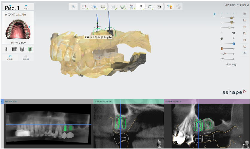
Рис. 1. Компьютерное планирование имплантации в области зубов 25, 26
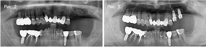
Рис. 2-3. Ортопантомограммы до и после хирургического вмешательства в области зубов 25, 26
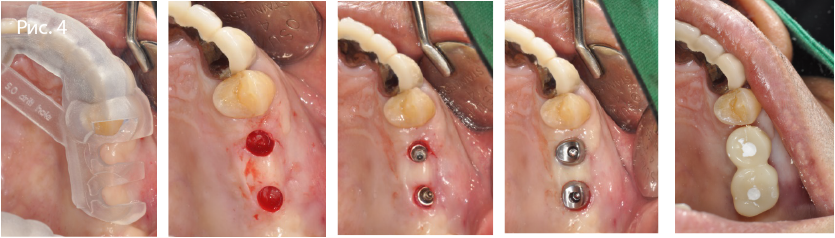
Рис. 4. Имплантация в боковом отделе верхней челюсти с применением хирургического шаблона
Клинический случай 2
Пациенту 65 лет с адентией в боковом отделе верхней челюсти слева установили имплантаты с помощью хирургического шаблона OneGuide и хирургического набора Osstem — OneGuide Kit. Для определения оптимального положения имплантатов использовали программное обеспечение Implant Studio (3Shape).
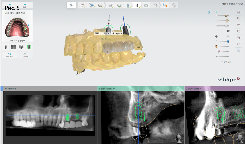
Рис. 5. Компьютерное планирование имплантации в области зубов 25, 27
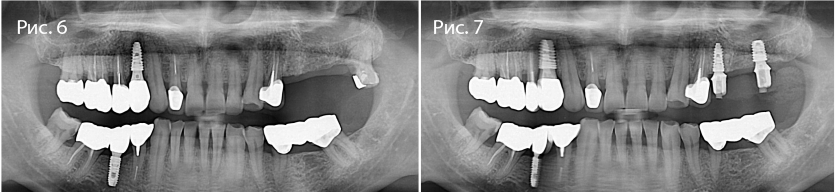
Рис. 6-7. Ортопантомограммы до и после хирургического вмешательства в области зубов 25, 27
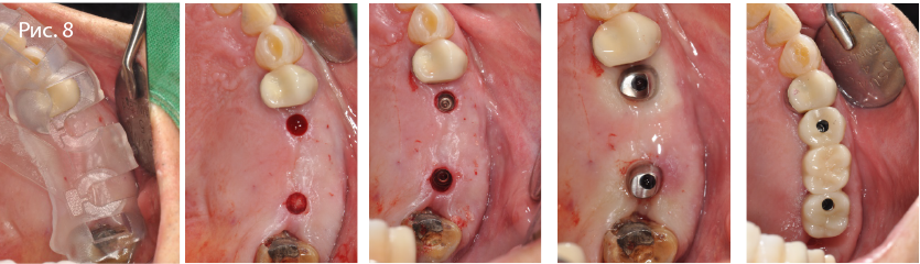
Рис. 8. Имплантация в боковом отделе верхней челюсти с применением хирургического шаблона
Результаты
Имплантаты успешно установили в правильном положении. Обе операции прошли без осложнений. Отклонение положения имплантата от запланированного в среднем составляло 0,15 мм и 0,1 мм на уровне шейки и апекса соответственно. Наклон оси отличался от заданного в среднем на 0,32°.
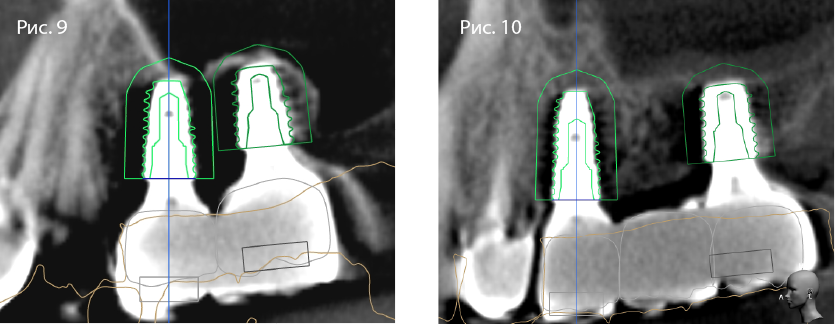
Рис. 9-10. Наложение снимка, полученного после операции, на результаты компьютерного планирования имплантации
Выводы
Результаты исследования подтверждают эффективность хирургических шаблонов OneGuide и качество набора для операции OneGuide Kit при установке имплантатов в соответствии с данными компьютерного планирования.
Всемирный конгресс Osstem
Шэньчжэнь 2017
Узнать больше о хирургическом наборе OneGuide Kit можно здесь
Рекомендованные статьи
Все статьи
-
Contents
-
Table of Contents
-
Bookmarks
Quick Links
K3 Unit Chair Installation
Osstem Implant
Technical Support Division
Related Manuals for Osstem Implant K3

Summary of Contents for Osstem Implant K3
-
Page 1
K3 Unit Chair Installation Osstem Implant Technical Support Division… -
Page 2
K3 Unit Chair Installation (Mechanical) Osstem Implant… -
Page 3
Contents K3 installation Checklist Ⅰ Select installation location Ⅱ K3 UNIT CHAIR Installation Ⅲ Pipeline installation Ⅳ Air / Water Line Diagram Ⅴ… -
Page 4
K3 Installation Ⅰ Checklist… -
Page 5
Ⅰ K3 Installation Checklist Packing Box Components 1. CHAIR BOX 2. UNIT BOX 3. TABLE BOX 4. LIGHT ARM BOX 5. LIGHT HEAD BOX 6. SEAT BOX 7. DOCTOR STOOL BOX… -
Page 6
Ⅰ K3 Installation Checklist Checklist before Installation • Check the product transportation route. • The product must be transported in a packed state. If packing materials need to be removed before transportation, soft materials must be used to prevent damage to the product. -
Page 7
Ⅱ Select installation location… -
Page 8
2.5m at least • Distance from piping to the spittoon must be within • Sufficient space must be secured for repair and maintenance • Support structure must be able to withstand the weight of equipment K3 Unit Chair Size §… -
Page 9
K3 UNIT CHAIR Installation Ⅲ… -
Page 10
Ⅲ K3 UNIT CHAIR Installation 『CHAIR Installation』 CHAIR INSTALLATION § Installation procedures #1 < Figure 01 > Wall 1. Install the base plate Piping position Large R size Narrow gaps Check the direction to place the main plate (A) on… -
Page 11
Ⅲ K3 UNIT CHAIR Installation 『CHAIR Installation』 CHAIR INSTALLATION § Installation procedures #2 < Figure 03 > 3. Install the chair assembly As shown in <Figure 03>, place the chair assembly (B) on the main plate (A), align the bolt hole positions and fasten the fixing bolts and level adjustment bolts, referring to <Figure 02>. -
Page 12
Ⅲ K3 UNIT CHAIR Installation 『CHAIR Installation』 CHAIR INSTALLATION § Installation procedures #3 < Figure 05 > 5. Install backrest bracket As shown in <Figure 05>, assemble the backrest bracket (D) to the backrest support ①. Use a Phillips screwdriver 6. -
Page 13
Ⅲ K3 UNIT CHAIR Installation 『CHAIR Installation』 CHAIR INSTALLATION § Installation procedures #4 < Figure 07 > 7. Install backrest cover Referring to <Figure 07>, align the heads of 4 bolts for the backrest cover (F) with the holes (b) of the backrest seat (E), and push the bolts down to insert them into the holes. -
Page 14
Ⅲ K3 UNIT CHAIR Installation 『CHAIR Installation』 CHAIR INSTALLATION § Installation procedures #5 < Figure 09 > 9. Install seat As shown in <Figure 09>, push the seat assembly (H) in the backrest direction to set the position to mount the seat assembly. -
Page 15
Ⅲ K3 UNIT CHAIR Installation 『CHAIR Installation』 CHAIR INSTALLATION § Installation procedures #6 < Figure 11 > 11. Remove the main power cable As shown <Figure 11>, remove the main power cable located in the chair assembly. 12. Assemble power switch <… -
Page 16
Ⅲ K3 UNIT CHAIR Installation 『CHAIR Installation』 CHAIR INSTALLATION § Installation procedures #7 < Figure 13 > 13. Assemble main power cable As shown in <Figure 13>, connect the connector. 14. Assemble power switch < Figure 14 > As shown in <Figure 14>, place the base front cover (J) on the base plate and fasten with bolts on both sides. -
Page 17
Ⅲ K3 UNIT CHAIR Installation 『CHAIR Installation』 CHAIR INSTALLATION § Installation procedures #8 < Figure 15 > 15. Install motor cover As shown in <Figure 15>, mount a hook (C) located on the front side of the motor cover (K) aligning with the groove on the base front cover (J). -
Page 18
Ⅲ K3 UNIT CHAIR Installation 『CHAIR Installation』 CHAIR INSTALLATION § Installation precautions #1 1. Align the backrest cover with the center of the headrest Good Example Bad Example Regular gaps Irregular gaps 2. Perform an armrest operating test to check whether there is any interference with… -
Page 19
Ⅲ K3 UNIT CHAIR Installation 『CHAIR Installation』 CHAIR INSTALLATION § Installation precautions #2 3. Chair levelness adjustment After installing the unit chair, check the levelness using a level gauge, and balance the unit chair using the levelness adjustment bolt shown in <Figure 01>. -
Page 20
Ⅲ K3 UNIT CHAIR Installation 『UNIT Installation』 UNIT INSTALLATION § Installation procedures #1 < Figure 01 > 1. Remove Unit Base Cover_R Unfasten 2 bolts as shown in <Figure 01> and remove the Unit Base Cover_R (A). Use a Phillips screwdriver 2. -
Page 21
Ⅲ K3 UNIT CHAIR Installation 『UNIT Installation』 UNIT INSTALLATION § Installation procedures #2 < Figure 03 > 3 Fasten levelness adjustment bolt As shown in <Figure 03>, temporarily fasten the levelness adjustment bolt for the unit to the Main Plate (C). -
Page 22
Ⅲ K3 UNIT CHAIR Installation 『UNIT Installation』 UNIT INSTALLATION § Installation procedures #3 < Figure 05 > 5. Remove bolt cap As shown in <Figure 05>, remove the rubber cap mounted on Unit Base Cover_L. 6. Remove fixing bolt < Figure 06 >… -
Page 23
Ⅲ K3 UNIT CHAIR Installation 『UNIT Installation』 UNIT INSTALLATION § Installation procedures #4 < Figure 07 > 7. Fix Unit Assembly As shown in <Figure 07>, fasten the bolt fixing the Main Plate (C) and the Unit Assembly (A) and tightly fasten the bolt that was temporarily fastened in Step 4. -
Page 24
Ⅲ K3 UNIT CHAIR Installation 『UNIT Installation』 UNIT INSTALLATION § Installation procedures #5 < Figure 09 > 9. Fix Assist Table Assembly As shown in <Figure 09>, fasten Unit Assembly (E) and Assist Table Assembly (F) using bolts. Use a Phillips screwdriver 10. -
Page 25
Ⅲ K3 UNIT CHAIR Installation 『UNIT Installation』 UNIT INSTALLATION § Installation procedures #6 < Figure 11 > 11. Assemble Back Low Cover As shown in <Figure 11>, align the Back Lower Cover (B) with the Assembly Ball and push it in the arrow direction to put the cover in ※… -
Page 26
Ⅲ K3 UNIT CHAIR Installation 『UNIT Installation』 UNIT INSTALLATION § Installation precautions 1. How to move Unit Assembly Dangerous point Safety When moving Unit Assembly, you must when lift up to move Section grab the safety point (position #2 and 3). -
Page 27
Ⅲ K3 UNIT CHAIR Installation 『TABLE Installation』 DOCTOR TABLE INSTALLATION § Installation procedures #1 < Figure 01 > 1. Install Large Arm Assembly As shown in <Figure 01>, level off the Large Arm Assembly (A) and put it in Unit Assembly ① in the vertical direction. -
Page 28
Ⅲ K3 UNIT CHAIR Installation 『TABLE Installation』 DOCTOR TABLE INSTALLATION § Installation procedures #2 < Figure 03 > 3. Insert Wire in Doctor Table Assembly As shown in <Figure 03>, hold the Doctor Table Assembly (B) and pass the wire through the inside of Large Arm (C) to insert it inside the unit. -
Page 29
Ⅲ K3 UNIT CHAIR Installation 『TABLE Installation』 DOCTOR TABLE INSTALLATION § Installation procedures #3 < Figure 05 > 5. Assemble Sub Table As shown in <Figure 05>, fasten Sub Table (E) to Sub Table Bar (F) with bolts. Use a Phillips screwdriver 6. -
Page 30
Ⅲ K3 UNIT CHAIR Installation 『TABLE Installation』 DOCTOR TABLE INSTALLATION § Installation procedures #4 < Figure 07 > 7. Install Chart Holder As shown in <Figure 07>, align and insert the Chart Holder (I) in the holes on Upper Table Block (H). -
Page 31
Ⅲ K3 UNIT CHAIR Installation 『TABLE Installation』 DOCTOR TABLE INSTALLATION § Installation procedures #5 < Figure 09 > 9. Assemble Mouse Pad As shown in <Figure 09>,insert the Mouse Pad (J) into the side of Doctor Table and fasten with bolts. -
Page 32
Ⅲ K3 UNIT CHAIR Installation 『TABLE Installation』 DOCTOR TABLE INSTALLATION § Installation procedures #6 < Figure 11 > 11. Mount Stainless Tray As shown in <Figure 11>, mount Stainless Tray (L) on the Sub Table (E). -
Page 33
Ⅲ K3 UNIT CHAIR Installation 『TABLE Installation』 DOCTOR TABLE INSTALLATION § Installation precautions #1 1. Level off Doctor Table As shown in the figure, remove the Table Cover. Adjust the wrench bolts shown in Figure «A» and «B“ and level off the Doctor Table. -
Page 34
Ⅲ K3 UNIT CHAIR Installation 『TABLE Installation』 DOCTOR TABLE INSTALLATION § Installation precautions #2 3. Balance Arm Tension Fixing Device Turn the Balance Arm Knob shown in Figure «D» counter- clockwise to lock it, and the load will be applied to the tension adjustment device, which leads to an increase in the fixing force of the Balance Arm. -
Page 35
Ⅲ K3 UNIT CHAIR Installation 『TABLE Installation』 DOCTOR TABLE INSTALLATION § Installation precautions #3 5. How to Adjust Water Volume for the Balance Arm Water volume adjustment valve is placed on the bottom right of the Doctor Table. Turn each valve clockwise to decrease the water volume;… -
Page 36
Ⅲ K3 UNIT CHAIR Installation 『MONITOR ARM Installation』 MONITOR ARM INSTALLATION § Installation procedures #1 < Figure 01 > 1. Install Light Pole As shown in <Figure 01>, level off the Large Arm (A) and insert the Light Pole (B) in the vertical direction. -
Page 37
Ⅲ K3 UNIT CHAIR Installation 『MONITOR ARM Installation』 MONITOR ARM INSTALLATION § Installation procedures #2 < Figure 03 > 3. Install Monitor Arm Support As shown in <Figure 03>, align Support_Left (C) and Support_Right (D) on Light Pole (B) and fasten with bolts. -
Page 38
Ⅲ K3 UNIT CHAIR Installation 『MONITOR ARM Installation』 MONITOR ARM INSTALLATION § Installation procedures #3 < Figure 05 > 5. Install Monitor Arm Assembly As shown in <Figure 05>, align and put the Monitor Arm Assembly (F) in the bolt holes on Support_Left (C) and Support_Right (D). -
Page 39
Ⅲ K3 UNIT CHAIR Installation 『MONITOR ARM Installation』 MONITOR ARM INSTALLATION § Installation procedures #4 < Figure 07 > 7. Insert Monitor Arm Wire As shown in <Figure 07>, pass the wire of Monitor Arm Assembly (F) through the Light Pole (B) to insert it into the unit. -
Page 40
Ⅲ K3 UNIT CHAIR Installation 『MONITOR ARM Installation』 MONITOR ARM INSTALLATION § Installation precautions 1. Installation direction of monitor arm < Figure 01 > Spittoon Monitor Arm When installing the monitor arm, install it at an angle of 30˚ (or 5 o’clock) when looking straight at the front surface of the Spittoon. -
Page 41
Ⅲ K3 UNIT CHAIR Installation 『DENTAL LIGHT Installation』 DENTAL LIGHT INSTALLATION § Installation procedures < Figure 01 > 1. Insert Wire in Light Arm Assembly As shown in <Figure 10>, pass the wire of Light Arm Assembly through the Light Pole ① to insert it in the unit. -
Page 42
Ⅲ K3 UNIT CHAIR Installation 『 HANARO CONSOLE Installation』 HANARO CONSOLE INSTALLATION § Installation procedures #1 < Figure 01 > 1. Assemble Main Body As shown in <Figure 01>, put the Support Insert (B) in the Main Body (A). 2. Assemble Pole Support <… -
Page 43
Ⅲ K3 UNIT CHAIR Installation 『 HANARO CONSOLE Installation』 HANARO CONSOLE INSTALLATION § Installation procedures #2 < Figure 03 > 3. Install Main Body As shown in <Figure 03>, fasten Main Body (A) and Pole Support (C) to Light Pole ① using bolts. -
Page 44
Ⅲ K3 UNIT CHAIR Installation 『 HANARO CONSOLE Installation』 HANARO CONSOLE INSTALLATION § Installation procedures #3 < Figure 05 > 5. Assemble Side Table As shown in <Figure 05>, put the Side Table (E) in the side groove on the Main Body (A) in the direction indicated by the arrow. -
Page 45
Ⅲ K3 UNIT CHAIR Installation 『 HANARO CONSOLE Installation』 HANARO CONSOLE INSTALLATION § Installation procedures #4 < Figure 07 > 7. Assemble Main Top Body Right As shown in <Figure 07>, put Main Top Body Right (G) over the Main Body (A). -
Page 46
Ⅲ K3 UNIT CHAIR Installation 『 HANARO CONSOLE Installation』 HANARO CONSOLE INSTALLATION § Installation precautions 1. Support Insert mounting position Good Good Mounting support part Mounting support part (main body side) (pole side) 2. How to assemble the Cup Ejector… -
Page 47
Pipeline installation Ⅳ… -
Page 48
Ⅳ Install pipelines How to Install Pipe A: Connect the spittoon drain line to the floor pipe. B: Connect the suction drain line to the CVS. (For air suction system, connect the line to the floor pipe) C: Connect to the water input line. D: Connect the air input to the compressor. -
Page 49
Air/Water Line Diagram Ⅴ… -
Page 50
Ⅴ Air / Water Line Diagram Basic System… -
Page 51
Ⅴ Air / Water Line Diagram Air Suction System… -
Page 52
Ⅴ Air / Water Line Diagram Water Sanitation System… -
Page 53
Thank you… -
Page 54
K3 Unit Chair Installation (Electrical) Osstem Implant… -
Page 55
Contents Electrical equipment installation Ⅰ Wiring test Ⅱ… -
Page 56
Ⅰ Electrical equipment installation… -
Page 57
Ⅰ Electrical equipment installation K3 PCB Harness Connection • Base Part, Unit Part (Light Part, Assist Part), Table Part § Parts and Components of K3 Unit Chair TABLE UNIT BASE… -
Page 58
Ⅰ Electrical equipment installation 『POWER PCB』 K3 PCB Harness Connection § K3 Base Part Position of Power PCB BASE… -
Page 59
Ⅰ Electrical equipment installation 『POWER PCB』 K3 PCB Harness Connection § Power PCB – Harness Connector Configuration (5 connections) ⑤ Hydraulic solenoid valve ④ Hydraulic motor ① MAIN PCB ② Suction device ③ POWER SWITCH… -
Page 60
Ⅰ Electrical equipment installation 『POWER PCB』 K3 PCB Harness Connection • Delivers chair operation signals from Main PCB to Channel and from Assist PCB to Power PCB § Power PCB – Main PCB Power Supply Harness Connection Power PCB MAIN PCB… -
Page 61
Ⅰ Electrical equipment installation 『POWER PCB』 K3 PCB Harness Connection • Delivers start signal for the suction device in the dental clinic § Power PCB – Suction Start Signal Configuration Power PCB MAIN Suction device… -
Page 62
Ⅰ Electrical equipment installation 『POWER PCB』 K3 PCB Harness Connection • Applies AC 220V to the dental clinic through the Main Switch when the Oil Motor and Oil Solenoid Valve are turned ON § Configuration between Power PCB – Power Supply(AC220V) -
Page 63
Ⅰ Electrical equipment installation 『POWER PCB』 K3 PCB Harness Connection • Converts the signal received from the Main PCB from weak current to strong current, and delivers the operating signal for Oil Solenoid Valve that corresponds to the Chair/Backrest Up/Down Selection value §… -
Page 64
Ⅰ Electrical equipment installation 『POWER PCB』 K3 PCB Harness Connection • If the value delivered from the signal received from the Main PCB and converted from weak current to strong current is a command to raise the chair/backrest, the signal is delivered to operate the oil motor… -
Page 65
Ⅰ Electrical equipment installation 『MAIN PCB』 K3 PCB Harness Connection § K3 Unit Part UNIT Position of Unit PCB… -
Page 66
Ⅰ Electrical equipment installation 『MAIN PCB』 K3 PCB Harness Connection § Components of K3 Unit Connection M⑭ Water Sol M⑮ Assist_1 M⑬ Assist_2 M① SENSOR ① ⑬ ⑮ ⑭ M⑫ Power PCB ⑫ M② Level VR M② M③ M③ DATA M⑪… -
Page 67
Ⅰ Electrical equipment installation 『MAIN PCB』 K3 PCB Harness Connection § Final assembly photo of K3 Unit Connection Front side Rear side… -
Page 68
Ⅰ Electrical equipment installation 『MAIN PCB』 K3 PCB Harness Connection § K3 Unit Connection Wiring Main/Light PCB Cover Power cover M⑫ M① M② M③ M①, M②, M③ M⑬ M④ M⑤ M⑥ M⑭ M⑦ M④, M⑤, M⑥, M⑦, M⑧, M⑨ M⑮… -
Page 69
Ⅰ Electrical equipment installation 『MAIN PCB』 K3 PCB Harness Connection § Sensor position and limit switch harness color Harness common SWITCH Color Up Limit Black, Green Down Limit Black, Blue Position Sensor Red,White,Black… -
Page 70
Ⅰ Electrical equipment installation 『FOOT PCB』 K3 PCB Harness Connection § Connect to Foot Harness à Main PCB M⑪ F② Foot Harness… -
Page 71
Ⅰ Electrical equipment installation 『FOOT PCB』 K3 PCB Harness Connection § Connect to Foot Harness à Main PCB M⑪ Foot Controller ⑪ F② FOOT V/R F② FROM FOOT CONTROLLER Main PCB… -
Page 72
Ⅰ Electrical equipment installation 『FOOT PCB』 K3 PCB Harness Connection • Delivers chair operation control signals via manual position button, rinsing and return buttons § Connect to Foot Harness à Main PCB Foot Pedal Foot PCB Main PCB ü Precautions: For Elec. Low HP, the foot pedal features a 3-pin harness (wire), which is intended to deliver RPM (speed) control signals for the Elec. -
Page 73
Ⅰ Electrical equipment installation 『LIGHT PCB』 K3 PCB Harness Connection § Light PCB — LIGHT HARNESS Connection L① LED Light L① L② Light Power L②… -
Page 74
Ⅰ Electrical equipment installation 『ASSIST PCB』 K3 PCB Harness Connection § Parts and components of K3 Assist PCB Table Assist Membrane Suction Syringe Suction Assist PCB Large Small… -
Page 75
Ⅰ Electrical equipment installation 『ASSIST PCB』 K3 PCB Harness Connection § Main PCB — Assist PCB Connection Suction Suction Assist PCB Power PCB Main PCB… -
Page 76
Ⅰ Electrical equipment installation 『TABLE PCB』 K3 PCB Harness Connection § K3 Table Part TABLE… -
Page 77
Ⅰ Electrical equipment installation 『TABLE PCB』 K3 PCB Harness Connection § Parts and components of K3 Table Electrical equipment Connection T⑪ Bien-air Power T⑬ Table Power T⑩ Scaler Power T⑩ T⑪ T⑬ T⑫ Fiber Optic T⑫ T⑨ Scaler Start T⑨… -
Page 78
Ⅰ Electrical equipment installation 『TABLE PCB』 K3 PCB Harness Connection • Check whether the copper plate is properly shielded in the event of an abnorm al phenomenon, such as the LCD window turning off or whitening while in use §… -
Page 79
Ⅰ Electrical equipment installation 『TABLE PCB』 K3 PCB Harness Connection • Take out the lock section in the connector and remove the film connection section § Table – Dr. Table Membrane Connection… -
Page 80
Ⅰ Electrical equipment installation 『TABLE PCB』 K3 PCB Harness Connection § Table – Bien-air Signal Connection Diagram K3 Table Board K3 Foot Controller Pedal On/Off ,Pedal AD CONV24 24Vac ±10% RS-232C (UART0) K3 Main Board 32Vdc ±10% TO MICROMOTOR(MCX) -
Page 81
Ⅰ Electrical equipment installation 『TABLE PCB』 K3 PCB Harness Connection • If the power supply line and the start signal line are switched with each other, it will cause a critical error in the Scaler PCB. § Table – SCALER Connection… -
Page 82
Ⅰ Electrical equipment installation 『Suction Connection』 K3 Suction Connection § Suction Micro S/W Suction circuit configuration ① Activated when either of them is lifted — parallel circuit DC24V Assist PCB… -
Page 83
Ⅰ Electrical equipment installation 『Power Connection』 K3 Power Connection § AC220V Power LINE Power PCB Noise Filter Main Switch Motor (AC220V) 10A Fuse Chair UP Chair DN B.Rest UP B.Rest DN Grounding TRANS B. AC24V AC220V L. AC12V AC24V… -
Page 84
Ⅰ Electrical equipment installation 『Power Connection』 K3 Power Connection § K3 Power Supply Diagram Scaler Main Table TRANS Bien Air DC24V Low HP B. AC24V AC24V Excelitas Light PCB L. AC12V : Fuse… -
Page 85
Ⅰ Electrical equipment installation 『Power Connection』 K3 Power Connection § K3 Electrical equipment Grounding Configuration Building groundin A total of 8 grounds Light Unit… -
Page 86
Ⅰ Electrical equipment installation 『Power Connection』 K3 Power Connection § K3 Main Switch Replacement Black INPUT OUTPUT OUTPUT Blue Black Blue INTPUT Brown Brown AC 220V input AC 220V output Blue Black Brown… -
Page 87
Wiring test Ⅱ… -
Page 88
Ⅱ Wiring Test 『LIGHT Test』 Light ON/OFF § Light On/Off Key Input Operation Basic operation Diagnosis Light bulb turns on when the operation is Light Signal PCB completed after pressing Light, M1, M2, M3, Check the light brightness change and RP keys Check the Membrane UI Check the brightness adjustment level… -
Page 89
Ⅱ 『LIGHT Test』 Wiring test Light ON/OFF § Functions of signal harness delivered to the light PCB — Supplies PCB operating power (DC 12V) — Delivers ON/OFF signal — Adjusts the halogen light’s brightness… -
Page 90
Ⅱ Wiring Test 『LIGHT Test』 Light ON/OFF § Light PCB Check and diagnosis Light PCB How to check Light PCB ① Check AC_IN, AC12V voltage — tester ① ② Perform 7A current test on the fuse ③ ② ③ Perform visual check on D2 LED (D2 LED is turned on/off when the Dr. -
Page 91
Ⅱ Wiring Test 『SUCTION Test』 Suction operation § Suction Operating Diagram Treatment office Machine room Suction Switch switch Signal Power PCB CVS Relay Suction AC110V… -
Page 92
Ⅱ Wiring Test 『SUCTION Test』 Suction operation § Suction signal check How to check the suction operation LED indicator — When turning On/Off: Displayed Suction Suction Assist PCB Power PCB Main PCB… -
Page 93
Ⅱ Wiring Test 『Chair operation test 』 Chair operation signal check § How to check the Power PCB operation LED indicator Hydraulic motor AC 220V Input Control Basic operation Checking operation Checklist function Operates when Hydraulic Measure the AC 220V voltage Check the motor LED chair goes up when the motor operates… -
Page 94
Ⅱ Wiring Test 『MAIN PCB』 Operating status between PCBs (chair operation) § AC24V main PCB power check Main PCB Checklist ① Connection of connector from the Trans DC 12V LED (water supply related) DC 24V LED Water Solenoid power supply ②… -
Page 95
Ⅱ Wiring Test 『MAIN PCB』 Operating status between PCBs (chair operation) § AC24V main PCB power check Main PCB Checklist ① Connection of connector from the Trans DC 5V LED Power supply to PCB ② If LED is not turned on, check the fuse for AC24V (B) Normal ③… -
Page 96
Ⅱ Wiring Test 『MAIN PCB』 Operating status between PCBs (chair operation) § Main PCB CPU activation check Main PCB Checklist ① Connection of connector from the Trans Check Table Power è ON/OFF LED ② If LED is not turned on, check the fuse for AC24V (B) Normal ③… -
Page 97
Ⅱ Wiring Test 『TABLE PCB』 Operating status between PCBs (chair operation) § DC5V Table PCB power check Table PCB Checklist ① Check the LED (table PCB power) operation Fuse for Table PCB DC 5V LED Power supply to table PCB IF DC 5V LED is OFF ②… -
Page 98
Ⅱ Wiring Test 『TABLE PCB』 Operating status between PCBs (chair operation) § DC24V Table PCB power check Table PCB Checklist ① Check the LED (HP Air/Water power) operation HP Air/Water control power fuse DC 24V LED Table HP Air/Water Power supply IF DC 5V LED is OFF ②… -
Page 99
Ⅱ Wiring Test 『TABLE PCB』 Operating status between PCBs (chair operation) § Table PCB CPU activation check Table PCB Checklist ① Connection of connector from the Trans Main Dr. Table Membrane Mirror : On/Off ② If LED is not turned on, check the table membrane and the communication line Normal ③… -
Page 100
Ⅱ Wiring Test 『SOL.VALVE』 Operating status between PCBs (chair operation) § HP Air/Water control solenoid valve power check 4-by-1 connection solenoid valve <How to measure> ⓐ Connect the tester to DC voltage. ⓑ Connect the lead wires of the tester to 2 terminals of the solenoid valve ⓒ… -
Page 101
Ⅱ Wiring Test 『OPTIC Test』 Operating status between PCBs (chair operation) § HandPiece(HP) Optic brightness adjustment check Lamp Table PCB H.P Optic HP Optic voltage LED : Max 3.2V Halogen : Max 2.9V Precaution: Please note that the LED lamp has polarity (+,-) -
Page 102
Ⅱ Wiring Test 『MICRO-SWITCH』 Operating status between PCBs (chair operation) § HandPiece (HP) detachment recognition Micro SW check HP-specific Micro SW LED check M4 M3 M3 M1 Table PCB… -
Page 103
Ⅱ Wiring Test 『MICRO-SWITCH』 Operating status between PCBs (chair operation) HandPiece (HP) detachment recognition Slot LED check § Check through HP-specific internal/external LED Table PCB… -
Page 104
Ⅱ Wiring Test 『FOOT Test』 Operating status between PCBs (chair operation) § Operation check between Main PCB and Foot PCB ※ LED illumination check Rinsing Position Return Position Pedal Chair Down Chair Up Backrest Down Backrest Up ü Ex1) When the pedal is pressed, the 3rd LED from the top illuminates ü… -
Page 105
Ⅱ Wiring Test 『Water Supply Test』 Operating status between PCBs (chair operation) § Operation check between Main PCB and Sensor PCB ü Water operation check Water continuously flows to the cup/spittoon • Check water penetration status at the manual assist membrane button Remove the manual connector button Manual water supply, drainage… -
Page 106
Ⅱ Wiring Test 『Water Supply Test』 Operating status between PCBs (chair operation) § Water level check between Main PCB and Sensor PCB ü Water level check Checking • — If the FULL LED is always turned on, check whether the cup level signal connector is flooded Troubleshooting •… -
Page 107
Ⅱ Wiring Test 『Water Supply Test』 Operating status between PCBs (chair operation) § Cup sensor operation Water supply Drainage Basic instructions Checklist Water supply is suspended when the cup is removed while water is Cup recognition supplied è 1 sec Drainage is suspended when the cup is recognized during drainage è… -
Page 108
Ⅱ Wiring Test 『Water Supply Test』 Operating status between PCBs (chair operation) Water Supply/Spittoon § Side Checklist Water supply instructions ① Water supply should be suspended when ① Place the cup at the cup holder position. the cup is removed while water is supplied ②… -
Page 109
Ⅱ Wiring Test 『Water Supply Test』 Operating status between PCBs (chair operation) § Water supply volume adjustment Water supply volume adjustment voltage (4 to 12V) Potential Level voltage Ref voltage(2V) Voltage Volume Water level recognition… -
Page 110
Ⅱ Wiring Test 『Water Supply Test』 Operating status between PCBs (chair operation) § K3 water supply cup recognition function Front Light emitting sensor Light receiving sensor Side Manual water supply and drainage Rear Sensor signal level signal… -
Page 111
Ⅱ Wiring Test 『KEY operation test』 Key operation test § Doctor Table Membrane Connection Test ü Connection procedures — Lift the connector, and detach or attach the film connection section — Perform a check on the operation of each key button — If any of the membrane keys are pressed èAll keys do not work è… -
Page 112
Ⅱ Wiring Test 『KEY operation test』 Key operation test § Doctor Table Membrane Defect Test Perform check on the operation of each of 23 keys ü Infinite value (normal) — Key is not pressed — Key is pressed, and does not return to the original position due to a lack of key tension — None of the keys work if any of the Dr. -
Page 113
Thank you… -
Page 114
K3 Unit Chair Installation (Settings) Osstem Implant… -
Page 115
Contents Adjust water volume for handpiece Ⅷ Check air at the inlet Ⅰ Check water injection at the inlet Check water sanitation operation Ⅱ Ⅸ Check water/air injection at handpiece Ⅲ Pneumatic control Ⅹ Limit and option settings Ⅳ Check foot pedal operation Ⅴ… -
Page 116
Check air at the inlet Ⅰ… -
Page 117
Ⅰ Check air at the inlet 『 Air Regulator 』 Air Regulator Pressure Check #1 Check air pressure § • Check whether the air pressure of the air regulator is 5 bar. Air Regulator 5 Bar… -
Page 118
Ⅰ Check air at the inlet 『 Air Regulator 』 Air Regulator Pressure Check #2 § Check air spray • Press the air spray button on the 3-way syringe to confirm that air comes out properly. Air spray button Water spray button 3-way syringe tip 3-way syringe… -
Page 119
Ⅱ Check water injection at the inlet… -
Page 120
Ⅱ Check water injection at the inlet 『 Check water injection 』 Inlet Water Injection Valve Check #1 § Check water injection valve • Open the water injection valve CLOSE OPEN Water injection Air injection line line… -
Page 121
Ⅱ Check water injection at the inlet 『 Check water injection 』 Inlet Water Injection Valve Check #2 § Check water injection of the 3-way syringe • Press the water spray button on the 3-way syringe to check whether water comes out properly. -
Page 122
Ⅲ Check water/air injection at handpiece… -
Page 123
Ⅲ Check water/air injection at handpiece 『 Handpiece 』 Water/Air Injection Check Detach the handpiece from the Dr.Table and turn water injection of § the handpiece ON. -
Page 124
Ⅲ Check water/air injection at handpiece 『 Handpiece 』 Water/Air Injection Check § Presss the foot pedal to check the operation and water injection of the handpiece. handpiece… -
Page 125
Limit and option settings Ⅳ… -
Page 126
Ⅳ Limit and option settings How to Set Limits • Setting limits enables the chair to recognize the position of limit resistance • You must perform this function after installing the chair 1. Press the LED LIGHT key and the RPM1 key simultaneously on the membrane of Dr.Table. Press simultaneously Enter the options mode menu 2. -
Page 127
Ⅳ Limit and option settings 『 Option settings 』 Option Settings § How to enter the options menu 1. Press the LED LIGHT key and the RPM1 key simultaneously on the membrane of Dr.Table. Press simultaneously Enter the options mode menu 2. -
Page 128
Ⅳ Limit and option settings 『 Option settings 』 Option Settings § How to exit options menu 1. After completing option mode settings, follow the steps described below to return to the treatment mode screen. Option mode screen Exit the option mode menu Treatment mode screen opens Press simultaneously… -
Page 129
Ⅳ Limit and option settings 『 Option settings 』 Option Settings § How to set option data 1. Move to Select Option Option mode screen Select option Move to Select Option + key — Key — Key Move to Select Option MODE key Select… -
Page 130
Ⅳ Limit and option settings 『 Option settings 』 Option Settings § Option function descriptions #1 Name LCD screen Description Settings OFF: disabled When you pick up the handpiece without pressing the (default) pedal Optic Hold • Optic of the handpiece turns on (ON) ON: enabled •… -
Page 131
Ⅳ Limit and option settings 『 Option settings 』 Option Settings § Option function descriptions #2 Name LCD screen Description Settings OFF: disabled At the time of chair operation (move), it stops Chair Wait (default) the chair operation for 1 second to prevent the patient’s hand from being caught by the Mode handle… -
Page 132
Ⅳ Limit and option settings 『 Option settings 』 Option Settings § Option function descriptions #3 Name LCD screen Description Settings OFF: disabled Select whether to use the backrest safety (default) BRest device Emergency — OFF (disabled) is the default setting ON: enabled When you install new firmware on the old PCB (version before 2015/6/22) -
Page 133
Ⅳ Limit and option settings 『 Option settings 』 Option Settings § Option function descriptions #4 Name LCD screen Description Settings Elec-High Configures settings for the instrument to be (default) installed on the 2nd holder of Dr.Table • Elec-High : High electric motor speed Air-High Instrument 2 •… -
Page 134
Ⅳ Limit and option settings 『 Option settings 』 Option Settings § Option function descriptions #5 Name LCD screen Description Settings AUTO: In the water supply settings for water supply to cup or spittoon Automatic water • When water is automatically supplied by the supply enabled Water cup sensor (AUTO) -
Page 135
Check foot pedal operation Ⅴ… -
Page 136
Ⅴ Check foot pedal operation 『 FOOT 』 Foot Pedal Operation Check #1 Try moving the position of the foot control using the foot control pedal. § § Try moving the chair and backrest up/down using the foot control joystick. Raise the chair Lower the chair Raise the backrest… -
Page 137
Ⅴ Check foot pedal operation 『 FOOT 』 Foot Pedal Operation Check #2 Try moving the chair to the rinsing position using the foot control button. § § Try moving the chair to the return position using the foot control button. Rinsing position Return position Rinsing Position… -
Page 138
Ⅵ Adjust chair/backrest speed… -
Page 139
Ⅵ Adjust chair/backrest speed How to Adjust Chair/Backrest Ascending Speed • Adjust the solenoid valve speed adjustment knob. • Turn clockwise to slow down. • Turn counter-clockwise to speed up. Lower Lower the the chair backrest Solenoid Valve Raise the Raise the chair backrest… -
Page 140
Adjust water volume for Ⅶ cup/spittoon… -
Page 141
Ⅶ Adjust water volume for cup/spittoon Spittoon Water Volume Adjustment • Adjust the water volume using the adjustment knob. Warmer On/Off Cup water volume adjustment knob Spittoon water volume adjustment knob (Spittoon) [User control section] ü Turning the adjustment knob clockwise increases the volume of water supplied to the spittoon ü… -
Page 142
Ⅶ Adjust water volume for cup/spittoon 『 Water outlet 』 Auto Cup Water Volume Adjustment #1 • Adjust the water volume using the adjustment knob on the main PCB to meet the needs of the water supply environment Tap water Tap water Salt water Salt water… -
Page 143
『 Water outlet 』 Ⅶ Adjust water volume for cup/spittoon Auto Cup Water Volume Adjustment #2 • Adjust the water volume using the adjustment knob. Warmer On/Off Cup water volume adjustment knob Spittoon water volume adjustment knob [User control section] ü… -
Page 144
Ⅶ 『 3-Way syringe 』 Adjust water volume for cup/spittoon How to Adjust Water Volume for 3-Way syringe (Assist Table) • Adjust the water volume using the adjustment pin. Adjustable 3-way syringe Water volume adjustment valve 3-way syringe Air volume adjustment valve Water volume adjustment valve on the spittoon ü… -
Page 145
Ⅶ 『 3-Way syringe 』 Adjust water volume for cup/spittoon Precautions When Adjusting Air / Water Pressure for 3-way Syringe (Assist Table) Balance between pin and block steps Pipeline is open Pipeline is open Pipeline is closed Pipeline is closed vPrecautions — The steps of the distribution block and the pin must be balanced. -
Page 146
Ⅷ Adjust water volume for handpiece… -
Page 147
Ⅷ Adjust water volume for handpiece Water Volume Adjustment for Devices How to adjust the water volume for Dr.Table devices § • Water volume adjustment knob: Turning the knob clockwise increases the water volume, and turning it counter-clockwise decreases the water volume Position of water volume adjustment knob… -
Page 148
Ⅸ Check water sanitation operation… -
Page 149
Ⅸ 『 Water sanitation 』 Check water sanitation operation Preset § Options menu settings • In the options menu, set the ‘W-Line-Clean Use’ item to ON. -
Page 150
Ⅸ 『 Water sanitation 』 Check water sanitation operation Water Sanitation Before leaving the office (chemical cleaning) § Takes about 7 minutes — Key… -
Page 151
Ⅸ 『 Water sanitation 』 Check water sanitation operation Water Sanitation After arriving at the office (water washing) § + key Takes about 10 minutes MODE key… -
Page 152
Pneumatic control Ⅹ… -
Page 153
Ⅹ Pneumatic control Handpiece Pneumatic Pressure Control How to adjust pneumatic pressure § • Air pressure of 3.5 bar is recommended for the handpiece. • Configure the air regulator settings and then the master block settings. • Configure settings considering the drop in pressure that occurs while the air passes through the pipe. -
Page 154
Ⅹ Pneumatic control Handpiece Pneumatic Pressure Control How to adjust the air regulator § • Using the adjustment knob, set the pressure to bar. Pressure gauge Filter ② Turn the pressure ① Pull the pressure ③ Push the pressure adjusting knob adjustment knob adjustment knob clockwise or counter-… -
Page 155
Ⅹ Pneumatic control Handpiece Pneumatic Pressure Control § How to adjust master block • Turning clockwise decreases the pressure. • Turning counter-clockwise increases the pressure. • Perform adjustment while checking the pressure gauge. • Set the pressure to 4 bar. Scaler High Speed Handpiece 1 Pressure gauge… -
Page 156
Ⅹ Pneumatic control 3-Way syringe Pneumatic Pressure Control §How to adjust 3-way syringe (assist table) air pressure • Adjust the air pressure using the adjustment pin. Adjustable 3-way syringe Water volume adjustment valve 3-way syringe Air volume adjustment valve Water volume adjustment valve on the spittoon ü… -
Page 157
Thank you…
Specifications:1637/1637015-k3.pdf file (03 May 2023) |
Accompanying Data:
Osstem Implant K3 Medical Equipment PDF Installation Manual (Updated: Wednesday 3rd of May 2023 12:29:48 PM)
Rating: 4.2 (rated by 12 users)
Compatible devices: truFreeze, Evita 4, HELION S, BP A100, microspeed uni, TIDAL WAVE 610, SlowJec plus DSD-PLA-0100, Akron Streamline 2 Section.
Recommended Documentation:
Installation Manual (Text Version):
(Ocr-Read Summary of Contents of some pages of the Osstem Implant K3 Document (Main Content), UPD: 03 May 2023)
-
58, Osstem Implant K3 58 Ⅰ Electrical equipment installation v K3 PCB Harness Connection BASE § K3 Base Part Position of Power PCB 『POWER PCB』
… -
11, Osstem Implant K3 11 Ⅲ K3 UNIT CHAIR Installation CHAIR INSTALLATION § Installation procedures #2 3. Install the chair assembly As shown in <Figure 03>, place the chair assembly (B) on the main plate (A), align the bolt hole positions and fasten the fixing bolts and level adjustment bolts, referring to <Fig…
-
95, 95 Ⅱ Wiring Test v Operating status between PCBs (chair operation) § AC24V main PCB power check 『MAIN PCB』 Main PCB Checklist ① Connection of connector from the Trans ② If LED is not turned on, check the fuse for AC24V (B) ③ Check the base end — Check the fuse in the noise filter — Check the trans Tr…
-
63, 63 OIL SOL. VALVE Ⅰ Electrical equipment installation v K3 PCB Harness Connection 『POWER PCB』 • Converts the signal received from the Main PCB from weak current to strong current, and delivers the operating signal for Oil Solenoid Valve that corresponds to the Chair/Backrest Up/Down Select…
-
71, 71 Ⅰ Electrical equipment installation v K3 PCB Harness Connection § Connect to Foot Harness à Main PCB 『FOOT PCB』 F② M ⑪ M⑪ Foot Controller F② FOOT V/R FROM FOOT CONTROLLER Main PCB
… -
8, 8 Ⅱ Select installation location Requirements for Installation Location • Must be level • A floor to ceiling distance must be secured 2.5m at least • Distance from piping to the spittoon must be within 2m • Sufficient space must be secured for repair and maintenance • Support structure must be abl…
-
127, Osstem Implant K3 127 Option Settings § How to enter the options menu Ⅳ Limit and option settings 1. Press the LED LIGHT key and the RPM1 key simultaneously on the membrane of Dr.Table. Press simultaneously Enter the options mode menu 2. Enter option 1 menu: Press the M2 key on the membrane of Dr.Table and select Option 1. 3. Ent…
-
Osstem Implant K3 User Manual
-
Osstem Implant K3 User Guide
-
Osstem Implant K3 PDF Manual
-
Osstem Implant K3 Owner’s Manuals
Recommended: GA-8I915GL-MF, 7853 — 30 in. Gas, IKF 249-5, DDX3216, GeForce Series
Product Types by Osstem Implant:
- Medical Equipment
Operating Impressions, Questions and Answers:
Южнокорейские имплантаты заслужили доверие стоматологов и активно используются во всем мире. Сегодня мы рассмотрим классическую линейку имплантатов TS от компании Osstem Implant. Osstem – один из крупнейших южнокорейских производителей, компания входит в мировой топ производителей имплантатов и занимает 1-ое место по популярности в Азиатско-Тихоокеанском регионе. Популярность Osstem в России также растет с каждым годом. В причинах успеха попробуем разобраться в этой статье.

Имплантаты с абатментом и одной коронкой.
Вы, конечно, слышали про имплантаты Osstem, даже если никогда не работали с ними. Компания Osstem Implant разрабатывает имплантационные системы с 1992 года. На сегодняшний день это один из самых быстро развивающихся производителей имплантатов. Продукция компании используется уже более чем в 70-ти странах мира, и зарабатывает все большую и большую популярность.
Причина успехов кроется в политики компании и ее целях. Огромное внимание уделяется научно-исследовательской работе. R&D Osstem – самый крупный центр исследований в области имплантологии в Южной Корее. Компания вносит вклад в изучение дентальной имплантологии и совершенствование глобальных технологий. Это позволяет ей не только иметь огромный успех на рынке, но и обеспечивать высочайшие стандарты качества, а также предлагать решения для каждого конкретного клинического случая.
Широкая линейка имплантатов и ортопедических компонентов позволяет найти индивидуальный подход и провести успешное, эстетичное лечение с учетом особенностей анатомического строения, добиться естественного внешнего вида и отсутствия дискомфорта у пациента.
Контроль качества на всех этапах производства обеспечивает максимальную точность исполнения и чистоту материалов. Заводы Осстем оборудованы по последнему слову техники и выпускают более 8 млн единиц в год. Обработка поверхности, режущая способность фрез, надежность продукции проверены и соответствуют международным стандартам качества.
Высокая первичная стабильность во всех вариациях дизайна линейки TS обеспечивает приживаемость имплантата и сокращает сроки лечения. Она достигается за счет трех особенностей:
- Конусный дизайн, который обеспечивает уплотнение кости вокруг имплантата;
- Активная резьба с высокой способностью к самонарезанию;
- Поверхность SA с пескоструйной обработкой и травлением кислотой обеспечивает раннюю остеоинтеграцию.
Резьба
Поговорим об уникальной резьбе имплантатов. Двойная резьба – 2 параллельных витка: сокращает время установки. За один оборот имплантат погружается на 2 шага. Быстрая щадящая установка снижает степень повреждения костной ткани вокруг имплантата. Помимо этого, агрессивная резьба имплантата с высокой способностью к самонарезанию позволяет стоматологу в процессе установке имплантата немного изменять, корректировать его направление — это часто бывает необходимо. Хирургу будет легко контролировать правильное направление установки имплантата.
Еще одним преимуществом серии является тройное внутреннее соединение с абатментом. Конус Морзе 11°- для плотного прилегания. Шестигранные соединения – для правильного позиционирования. Внутренний винт со специальным напылением Ebony Gold – для улучшенного соединения и защиты деталей. Это обеспечивает плотность соединения, максимальную надежность и безопасность конструкции в долгосрочном периоде.
Материалы
Качество имплантатов во многом определяют материалы, из которых он сделан. Имплантаты Osstem TS производятся из титана класса 4, что обеспечивает оптимальную прочность и биосовместимость.
Сплав Ti-6Al-4V класса 5 обладает повышенной прочностью и используется для производства абатментов, винтов и установочных адаптеров.
Поверхность имплантатов проходит так называемую обработку SA — пескоструйную обработку крупными частицами алюминия и травления сильными кислотами. Пескоструйная обработка создает кратеры на поверхности 100 мкр., а травление кислотами создает микро-кратеры 1-3мкр. Такая шероховатость дает высокую первичную стабильность во время заживления и раннюю остеоинтеграцию (более быстрое приживление) благодаря быстрому формированию кости. Качество материалов и технологичность обеспечивают высокую приживаемость будущего «зуба». Внимание уделено всем деталям и компонентам.
Система Osstem TS – самая ходовая линейка от компании Osstem. Она включает 3 вида дизайна имплантатов для разных клинических случаев и типов кости, а также вариации поверхностей SA и CA. Устанавливать имплантаты можно по упрощенному протоколу в зависимости от типа костной ткани.
TS III SA

Имплантаты TS III SA.
Имплантаты TS III SA — Коническая форма с углом конуса 1,5’.
Это наиболее универсальный, и потому часто используемый представитель линейки.
Дизайн в виде конуса обеспечивает уплотнение кости вокруг имплантата. А активный режущий край резьбы создает эффект самонарезания. Все это обеспечивает высокую первичную стабильность даже в условиях мягкого типа кости.
Сочетание оптимального дизайна и метода обработки поверхности SA гарантирует качественный и долгосрочный результат.
Диаметры: 3.0, 3.5, 4.0, 4.5, 5.0, 5.5, 6.0, 7.0.
Длина: 6, 7, 8.5, 10, 11.5, 13, 15 мм.
Зачастую, у имплантологов возникают проблемы с эстетикой протезирования в условиях узкого гребня и межзубного расстояния, например, для нижних резцов. Для этих целей в линейке TS III есть имплантаты диаметром 3.0, которые легко решают эту задачу.
TS IV SA

Имплантаты TS IV SA.
Имплантаты TS IV SA — Коническая форма с углом конуса 6’
Эти имплантаты созданы специально для установки в условиях мягкой кости, в частности для синус-лифтинга. Повышенная первичная стабильность в условиях мягкой кости обеспечивается более выраженным конусом в верхней части имплантата (6’) и активной резьбой.
Рекомендуемый крутящий момент: 40 НСМ.
Диаметры: 4.0, 4.5, 5.0.
Длина: 7, 8.5, 10, 11.5, 13 мм.
TS II SA

Имплантаты TS II SA.
Имплантаты TS II SA — Цилиндрическая форма.
Специальный дизайн для работы в условиях плотной кости. Мелкая резьба в области шейки имплантата защищает от перегрева кости и снимает напряжение кортикальной кости при установке и функционировании имплантата. Цилиндрическая форма позволяет обеспечить лучший контроль направления установки. Обеспечивает стабильность даже после повторной установки.
Рекомендуемый крутящий момент: 40 НСМ.
Диаметры: Ø 3.5, Ø4.0, Ø4.5, Ø5.0.
Длина: 7мм, 8.5мм, 10мм, 11.5мм, 13 мм.
TS III СA

Имплантаты TS II CA.
Кроме этого, для имплантатов TS III есть вариант линейки с гидрофильной поверхностью CA, помещенной в раствор кальция. Такая поверхность сохраняет все характеристики поверхности SA, но при этом остеоинтеграция происходит быстрее. Благодаря высокой гидрофильности к крови обеспечивается ускоренный остеогенез, ионы кальция формируют полноценный кровяной сгусток.
Диаметры: 3.5, 4.0, 4.5, 5.0, 5.5, 6.0, 7.0.
Длина: 7, 8.5, 10, 11.5, 13 мм.
Вывод
Osstem Implant — узнаваемый бренд. Компания с многолетней историей который год подтверждает свой статус производителя продукции высокого качества и разработчика новых технологий в области имплантологии. Упрощенные протоколы установки и новые цифровые решения делают работу имплантологов более простой и точной. А система поддержки врачей, образовательных курсов и семинаров Osstem совершенствует мастерство имплантологов по всему миру.
Отменное качество исполнения, высокая первичная стабильность и приживаемость имплантатов, широкая линейка с решениями для каждого индивидуального случая – все это поддерживает популярность Osstem на российском рынке. А доступная цена, не привязанная к курсу доллара, особенно радует в условиях кризиса.
Приобрести имплантаты TS от компании Osstem вы сможете перейдя по ссылке.
>Размеры имплантов Osstem
Импланты «Осстем» имеют различные размеры, что позволяет выбрать среди них вариант для практически любых ситуаций.
|
Вид имплантов марки Osstem |
Доступные длины, мм |
Доступные диаметры, мм |
|
TS-III SA |
6; 7; 8,5; 10; 11,5; 13; 15 |
3; 3,5; 4; 4,5; 5; 5,5; 6; 7 |
|
TS-IV SA |
7; 8,5; 10; 11,5; 13 |
4; 4,5; 5 |
|
TS-II SA |
7; 8,5; 10; 11,5; 13 |
3,5; 4; 4,5; 5 |
|
MS |
6; 7; 8,5; 10; 11,5; 13 |
1,8; 2; 2,5; 3 |
Материалы для производства имплантов Osstem
Для производства имплантов марки «Осстем» используют титан высокой степени очистки (4 класс, Grade 4) с высокой биосовместимостью. Данный материал не вызывает аллергических реакций со стороны мягких и костных тканей, то есть не может стать причиной отторжения. Применение титана 4 класса является стандартом при производстве имплантов.
Состав сплава титана для имплантов Osstem включает:
-
99% титан высокой степени очистки;
-
0,5% кислород;
-
0,5% железо;
-
0,1% углерод;
-
0,05% азот;
-
0,015% водород.
Титан марки Grade 4 не включает таких примесей, как алюминий или ванадий. Именно эти элементы способны вызвать аллергическую реакцию со стороны организма.
Титановое основание имплантов Osstem дополнительно подвергается пескоструйной обработке и травлению кислотой. В результате на поверхности появляются микропоры для прорастания костной ткани пациента и более крепкого сцепления импланта и кости челюсти.
Для производства абатментов и других деталей имплантационных систем «Осстем» применяет сплав Ti-6aL-4V с повышенными прочностными характеристиками.
Протокол протезирования Osstem
Имплантация Osstem возможна при немедленной и отсроченной нагрузке при восстановлении одного, нескольких или всех зубов.
Доступные протоколы внутрикостной дентальной имплантации Osstem:
Двухэтапная. Восстановление утраченного зуба происходит в 2 этапа. Первый – хирургический – включает подготовку к имплантации и установку импланта. После этого имплант оставляют приживаться на срок 4-6 месяцев. Второй этап – ортопедический – включает установку абатмента и коронки (или мостовидного протеза). Протокол применяется при восстановлении жевательных зубов. Использовать импланты Osstem можно на нижние и верхние жевательные зубы.
Одноэтапная. Установка импланта и его нагрузка временной коронкой происходят друг за другом без ожидания приживления искусственного корня. Постоянный протез устанавливают после приживления импланта. Методику применяют при восстановлении передних зубов.
All-on-4 и All-on-6. Восстановление зубов всей челюсти на 4 или 6 имплантах также относится к категории одноэтапной имплантации. Облегченный временный мостовидный протез устанавливают сразу после вживления 4 или 6 искусственных корней. Постоянную конструкцию крепят только после их полного приживления.
Одномоментная. В некоторых случаях установить имплант можно в лунку только что удаленного зуба. Это возможно при достаточном объеме костной ткани и отсутствии признаков воспаления вокруг удаленной единицы. Методику применяют для зубов с одним корнем.
Коронки на импланты Osstem
Ортопедический этап при работе с имплантами бренда «Осстем» в целом не отличается от работы с имплантатами других марок. При внедрении искусственных корней данного бренда можно выполнить протезирование:
-
единичными коронками;
-
мостовидными протезами на несколько зубов или всю челюсть.
-
Возможные материалы для изготовления протезов также не ограничены:
-
более дорогие диоксид циркония и керамика для реставраций в зоне улыбки;
-
бюджетная металлокерамика для жевательных зубов;
-
мостовидные протезы из композитных материалов с металлической балкой и искусственной десной при протезировании «Все на 4» и «Все на 6».
Сравнение «Осстем» с аналогами других систем имплантации
Большинство имплантологов работает с несколькими производителями, так как это расширяет возможности специалиста и выбор для пациента.
В сравнении с премиальными швейцарскими брендами Straumann и Nobel Biocare, Osstem не предлагает такого разнообразия систем и имплантов для осложненных ситуаций. Но показатели приживаемости этих брендов находятся примерно на одном уровне, поэтому стоматологи нередко предлагают пациентам без сложных клинических ситуаций бюджетный «Осстем».
К числу премиальных имплантов относится и шведский бренд Astra Tech. Импланты этой марки имеют самую высокую приживаемость (99,9%) и заслуженно входят в тройку лучших имплантационных систем мира. «Осстем» вполне успешно конкурирует и с этим гигантом, в основном за счет сочетания высокого качества и бюджетной стоимости.
Южнокорейские бренды Osstem и Dentium являются лидерами рынка среди ряда других компаний из азиатского региона. «Дентиум» вышел на рынок чуть позже, чем «Осстем» (1997 и 2000 годы), но активно развивается, предлагает новые решения и дает пожизненную гарантию на свои изделия. Dentium выпускает импланты под маркой Implantium. Как и «Осстем» — это бюджетный бренд с высоким качеством. Обе компании предоставляют обучение для стоматологов и представлены в России.
Еще один южнокорейский бренд Anyone только начинает завоевывать мировой рынок. Качество этих систем находится примерно на одном уровне с Osstem и Dentium, но по популярности и количеству применений в России они пока уступают более известным компаниям из Южной Кореи.
Примерно на одном уровне с Osstem находятся импланты израильского производства. Это бренды MIS и Noris Medical. В сравнении с южнокорейскими аналогами, израильские компании могут похвастаться более длительной историей и базой исследований. При этом импланты данных стран находятся в одном ценовом диапазоне. Израильские импланты MIS имеют специальное покрытие с повышенной гидрофильностью, что выделяет их на фоне Osstem. В линейке Noris представлен более широкий выбор конструкций, например, скуловые импланты.
Аналоги имплантов Osstem
В качестве замены для имплантов марки «Осстем» рекомендуют премиальные Straumann, Nobel или Astra Tech. Эти бренды имеют более длительную историю развития, расширенные каталоги и линейки систем имплантации практически для любых клинических случаев.
Отзывы на импланты Osstem
Глушаков Вячеслав Александрович, стоматолог-имплантолог клиники «All Smiles»:
Импланты Osstem – хороший бюджетный вариант при имплантации без серьезных нюансов. Если у пациента достаточный объем кости, нет проблем с деснами, то с удовольствием рекомендую Осстем как недорогой и качественный имплантат. Изделия бренда используем при единичном восстановлении, по протоколам All-on-4, All-on-6. Хорошо себя зарекомендовали мини импланты линейки MS, которые подходят пациентам с узким альвеолярным гребнем.
Вера Н., пациент клиники «All Smiles»:
В клинике «…» протезировала удаленную шестерку на нижней челюсти. По рекомендации доктора установили корейский имплант Осстем. Он оказался намного дешевле известных Штрауман, но по качественным показателям почти идентичен. Благодарна стоматологу за рекомендацию и экономию моего бюджета. На сэкономленные деньги после приживления поставила на имплант циркониевую коронку. Очень довольна качеством услуг и результатом!
Николай Геннадьевич, пациент клиники «All Smiles»:
Восстановили всю нижнюю челюсть на 4 имплантах. Когда считали стоимость имплантации с европейскими штифтами вышла неподъемная сумма, а вот корейские Осстемы с временным протезом вышли недорого. Пока жду полного приживления, жалоб на импланты нет. Рад, что есть такие качественные и бюджетные аналоги дорогим западным разработкам. Спасибо братьям азиатам за недорогие импланты!
Частые вопросы
Сколько служат импланты Osstem?
Производитель заявляет срок службы до 25лет. Именно на этот период рассчитана гарантия на все искусственные титановые корни марки. Отсчет гарантийного срока ведут с момента вживления. При этом при должном уходе штифт может служить в течение всей жизни.
Какую гарантию дает производитель на импланты Osstem?
Гарантия Osstem распространяется на всей импланты и системы бренда при соблюдении ряда условий. В их числе использование комплектующих только марки «Осттем», соблюдение протокола установки и гигиены полости рта после вживления. При наступлении гарантийного случая – отторжения импланта – пациенту следует собрать пакет документов и направить их в российский офис компании. В пакет документов входят указание номера и кода импланта, рентгеновские снимки до и после установки, отторгнутый имплант и заявка на обмен. Компания бесплатно предоставит новый имплант или его аналог, но не компенсирует расходы на его замену.
Из чего складывается цена имплантации «под ключ» с имплантами Osstem?
Помимо стоимости самого импланта в нее входят расходы на диагностические процедуры, оплату работы хирурга-стоматолога, комплектующих системы, изготовление коронки или моста. Имплантация системами «Осстем» относится к категории бюджетных, что достигается за счет невысокой стоимости имплантов, абатментов и других комплектующих бренда.
Доступна ли одномоментная имплантация системой Osstem?
Импланты марки «Осстем» подходят для одномоментной имплантации с немедленной нагрузкой, в том числе при установке мостовидного протеза на 4 или 6 искусственных корнях. В этих ситуациях лучше использовать варианты с покрытием SOI, которое обеспечивает ускоренное приживление штифта.