Одноступенчатый насос НД и трёхступенчатый насос ВД расположены друг за другом на валу насоса и закреплены вместе гайкой рабочего колеса. Встречное расположение рабочих колёс насосов НД и ВД обеспечивает практически полную компенсацию осевого давления, так что подшипники вала насоса подвергаются минимальной нагрузке.

Вал насоса изготовлен из нержавеющего и кислотостойкого материала.
Между блоком НД и блоком ВД насоса находится переключающий клапан (J19), при помощи которого обслуживающий персонал производит переключения при смене режима работы.
В корпусе между блоками НД и ВД находится небольшое отверстие. Через это отверстие, а также посредством поступления воды из средней сальниковой набивки, в блок ВД поступает достаточное количество воды. Эта вода поступает через переключающийся клапан обратно в камеру всасывания, чем предотвращает перегрев насоса до тех пор, пока из блока НД забирается вода. В корпус НД встроен термоэлемент (ДТВ), который по достижения температуры воды +55°С подает команду на включение предупреждающего звукового сигнала на дисплее насосного отсека, при этом открывается клапан заполнения цистерны (J31) и нагретая вода направляет в цистерну, процесс циркуляции продолжается пока температура корпуса насоса не опуститься ниже +5°°С. В режиме работы с пеной для охлаждения насоса водо-пенная смесь выводится наружу через патрубки слива воды из насоса до достижения температуры ниже 500С.
В течении 10 сек звучит предупреждающий сигнал.
Контрмера: Для того чтобы охладить насос достаточно открыть на некоторое время один из вентилей подачи воды, или уменьшить обороты насоса до оборотов холостого хода
При установки клапана переключения в верхние положение (НД)
блок НД насоса отделен от блока ВД. Через отключение блока ВД достигается повышение производительности блока НД. Режим НД используется в случаях, когда ВД не требуется. Это защищает насос от перегрева и снижает износ блока ВД.
При установке клапана переключения в нижнее положение (НД/ВД)
открывается соединяющий канал между блоком НД и блоком ВД, что позволяет работать одновременно в режимах НД и ВД. При использовании системы FIX MIX пенно — воденная смесь, по этому каналу поступает из блока НД в блок ВД, а от туда подается в патрубки высокого давления.
Вал насоса в корпусе редуктора насоса опирается на два шарикоподшипника, в корпусе НД на один игольчатый подшипник. Игольчатый подшипник смазывается с помощью ниппеля установленного в корпусе НД.
Вал насоса уплотнён как с всасывающей стороны, так и со стороны давления с помощью осевого контактного уплотнительного кольца.
Корпус насоса, а также рабочее и направляющее колёса, сделаны из бронзы или из коррозионно-устойчивого лёгкого металла.
В корпусе НД и ВД предусмотрены входы для подключения манометров, вакуумметра, вакуумного насоса и поступления воды от эжектора. В самом низком месте корпуса НД и ВД установлены штуцера для слива воды из насоса.
Нужно обратить особое внимание на то, чтобы насос не работал слишком долго с закрытыми напорными вентилями (при этом происходит сильный нагрев воды в корпусе насоса).
Если подача воды прекращается на продолжительное время, насос необходимо отключить.

Положение (НД/ВД) является основным для
комбинированного режима работы насоса.
Источник статьи: http://zinref.ru/000_uchebniki/03850pojarnoe_delo/006_00_Rukovodstvo_po_expluatatsii_ATs_3_2_40_4_43523_redaktsia_2011g/009.htm
Практическая работа на пожарном насосе Rosenbauer NH-30 АЦ 3,2-40-4 КамАЗ 5387
АЦ 3,2-40-4 на шасси КАМАЗ 5387 4х4 предназначена для доставки к месту пожара личного состава, огнетушащих средств, пожарно-технического вооружения и аварийно-спасательного инструмента. На АЦ установлен центробежный комбинированный пожарный насос NH-30 с автоматической системой пеносмешения FIX-MIX.
Читайте также: Водяной насос ваз 21116
При включение зажигания или включателя (i) на дисплее появляется изображение, на котором отображается состояние всех откидных площадок, шторных дверей, задней двери, двери надстройки. Затем появляется изображение, на котором показано содержимое емкостей с ОТВ, состояние сигнальных огней, фонарей ближнего света, включение лафета.
Включение зажигания или включателя
Работа из насосного отсека ступенью нормального давления
Подача воды из цистерны
- Запустить насос нажатием на клавишу включения насоса (привод насоса включается после 7 сек задержки).
- Войти в меню «РАБОТА С ВОДОЙ».
- Нажать клавишу F5 (автоматическое удаление воздуха).
Далее включается вакуумный насос и в автоматическом режиме происходит удаление воздуха и полости насоса, работа вакуумного аппарата прекратится автоматически при наборе около 2 кг/см 2 . В процессе создания разряжения возможно увеличение скорости набора путем нажатия клавиши «+».
- Открыть вентили выкидных патрубков насоса.
- Увеличить обороты насоса путем нажатия клавиши «+».
- Вода подается в очаг пожара! На дисплее отображается текущее количество ОТВ.
- При падения уровня воды ниже 25% раздается звуковой сигнал, а на экране появляется соответствующая надпись.
- При падение уровня воды ниже 10% появляется соответствующее предупреждение.
- Когда цистерна почти пуста! Снизить давление нажатием кнопки «-».
- Отключить насос путем нажатия клавиши «О».
Предупреждение! Запрещается работа насоса без воды более трех минут.
Подача воды из открытого водоема
- Присоединить линию к насосу.
- Присоединить напорные линии к насосу.
- Открыть задвижку заборного патрубка.
- Для забора воды, войти в меню «РАБОТА С ВОДОЙ».
- Нажать клавишу F5 (включение вакуумного насоса).
- Для ускорения забора воды увеличить обороты насоса нажатием клавиши «+».
Предупреждение! Запрещается увеличение оборотов насоса при работе вакуумного насоса выше 2500 об/мин.
Предупреждение! Напорные патрубки автоцистерны снабжены обратными клапанами, что позволяет производить забор воды с предварительно открытыми напорными выходами!
- Как только давление на выходе из насоса поднимется до 2 атм работа вакуумного насоса прекратится автоматически, обороты снизится до минимального значения. Увеличить обороты нажатием клавиши «+».
Заполнение цистерны из открытого водоема
- Для заполнения автоцистерны произведите установку на открытый водоисточник.
- Войти в меню «РАБОТА С ВОДОЙ».
- Нажать клавишу F3 (подача воды в цистерну от насоса).
Предупреждение! При заполнение цистерны на 90% обороты насоса автоматически снижаются до минимальных. С началом работы «переливного» патрубка произвести выключения заполнения повторным нажатием клавиши F3.
Забор и подача воды из открытых водоисточников с использованием гидроэлеватора Г-600
Предупреждение! При работе с гидроэлеватором ОБЯЗАТЕЛЬНО наличие воды в цистерне.
- Присоединить рукав диаметром 66мм к напорному выходу автоцистерны.
- Другим концов присоединить ко входу гидроэлеватора.
- Рукав диаметром 77 мм одним концом присоединить к выходу гидроэлеватора.
- Другим концом к гидрантному входу автоцистерны.
- Погрузить гидроэлеватор в водоем.
- Присоединить напорные линии к насосу.
- Для запуска гидроэлеватора в работу зайти в меню «РАБОТА С ВОДОЙ» и нажать клавишу F1.
- Нажатием на клавишу «+» увеличить давление до 5 атм.
- Плавно открыть задвижку соединенную со входом в гидроэлеватор.
- Когда произойдет заполнение линии и вода начнет поступать в насос увеличить обороты до необходимых, но не превышая 10 атм на выходе.
- Подать воду на ствол открыв вентиль напорного выхода.
Предупреждение! Контроль заполнения цистерны эжектируемой водой производить по дисплею ЕСЛИ уровень воды падает, то на тушение пожара расходуется количество воды большее эжектируемой ЭТО НЕДОПУСТИМО!
- В этом случае необходимо уменьшить расход воды на стволе, и увеличить давление на насосе.
Предупреждение! Когда произойдет заполнение цистерны на 90 % режим автоматического заполнения отключится, ЧТО МОЖЕТ ПРИВЕСТИ К ГИДРОУДАРУ!
- Для предотвращения гидроудара следует заблаговременно снизить обороты насоса.
Читайте также: 96396602 насос омывателя в нижнем новгороде
Подача воды от гидранта
- Автоцистерна снабжена специальной гидрантной линией с двумя входами, позволяющей снабжать насос от гидранта без применения водосборника ВС-125.
Предупреждение! Запрещается подключать к гидрантным входам автоцистерны источник питания с давлением выше 8 атм.
- Установить колонку и подключить напорно-всасывающие рукава к гидрантным входам автоцистерны.
- Присоединить напорные линии к насосу.
- Войти в меню «РАБОТА С ВОДОЙ».
- Нажать клавишу F2 (снабжать насос водой непосредственно от водоема).
- Открыть вентили напорных выходов.
- Увеличить давление на выходе нажатием клавиши «+».
Заполнение цистерны от гидранта
Примечание! Конструкция водопенных коммуникация автоцистерны позволяет наполнить цистерну без заполнения насоса.
- Войти в меню «РАБОТА С ВОДОЙ».
- Нажать клавишу F1 (автоматически наполнить бак водой от водоема регулятором уровня).
- Заполнение цистерны до уровня 90% происходит в автоматическом режиме, о включение автоматики заполнения сигнализирует пиктограмма «РЕГУЛЯТОР».
- Полное заполнение цистерны возможно в ручном режиме, для этого в меню «РАБОТА С ВОДОЙ» нажать и удерживать клавишу F4.
- С началом работы переливного патрубка отпустить F4.
- Цистерна заполнена.
Работа на гидранте в режиме автоматической подпитки цистерны
Примечание! Конструкция водопенных коммуникаций позволяет автоматически наполнять цистерну по мере расходования воды, если гидрантная линия подключена к насосу, либо другому источнику воды.
- Открыть вентили выкидных патрубков насоса.
- Вода подается в очаг пожара, для включение автоматики наполнения цистерны необходимо войти в меню «РАБОТА С ВОДОЙ» и нажать клавишу F1 (о включение режима сигнализирует пиктограмма «РЕГУЛЯТОР».
- При снижение уровня воды в цистерне ниже 60% автоматически открывается клапан заполнения цистерны от гидрантной линии, и выключается при уровне 90%.
Работа из насосного отсека ступенью высокого давления
- Вынуть из держателя ствол ВД и размотать катушку.
- Запустить насос.
- Войти в меню «РАБОТА С ВОДОЙ».
- Нажать клавишу F5 (автоматическое удаление воздуха). Далее включается вакуумный насос и в автоматическом режиме происходит удаление воздуха и полости насоса, работа вакуумного аппарата прекратится автоматически при наборе около 2 кг/см 2 .
- Включить ступень ВД плавным поворотом рукоятки «от себя» до упора.
Предупреждение! Запрещается включать и выключать ступень ВД при оборотах насоса выше 2500 об/мин
- Для подачи воды через катушку войти в меню «РАБОТА С ВЫСОКИМ ДАВЛЕНИЕМ».
- Для открытия подачи нажать клавишу F3.
- Увеличить давление на выходе нажатием клавиши «+».
Работа с пенообразователем
От цистерны
- Присоединить пенный ствол.
- Запустить насос.
- Открыть вентили выкидных патрубков насоса.
- Для включения пеносмешения зайти в меню «РАБОТА С ПЕНООБРАЗОВАТЕЛЕМ».
- Для выбора кратности нажать клавишу F2.
- Для включения пеносмешения нажать клавишу «ВВОД».
- Воздушно-механическая пена подается в очаг пожара! На дисплее отображается текущий уровень пенообразователя.
От сторонней емкости
- Другим концом погрузить в емкость.
- Открыть кран забора пенообразователя из сторонней емкости. При открытие крана на экране появляется изображение сопровождаемое звуковым сигналом.
- Перейти в меню «РАБОТА С ПЕНООБРАЗОВАТЕЛЕМ».
- Перейти на забор пенообразователя из сторонней емкости, для чего нажать клавишу F4.
- Для включения пеносмешения нажать клавишу «ВВОД».
- Пенообразователь забирается из сторонней емкости.
Предупреждение! Во избежание порчи насоса и водопенных коммуникаций после работы с пенообразователем необходимо выполнить промывку.
- Режим промывки становится единственным активным после любых работ с пенообразователем и выполняется на автоцистерне подающей воду.
- Для включения промывки войти в меню «ПРОМЫВКА / СЛИВ» и нажать клавишу F1.
- Запущен режим автоматической промывки! Промывка производится до прекращения появления пены.
- Для промывки рукава КЩ-32 открыть кран забора пенообразователя из сторонней емкости при включенном режиме промывки.
- Для остановки промывки повторно нажать клавишу F1.
Читайте также: 96401942 grundfos насос ups 40 120 f 1х230v циркуляционный промышленный
Подача через лафетный ствол
- Включить лафетный ствол нажатием ЗЕЛЕНОЙ клавиши на джойстике.
- Для работы с пенообразователем нажать клавишу F1 на дисплее водителя.
- Для выбора кратности нажать F2.
- Для включения пеносмешения нажать клавишу «ВВОД».
- Включить подачу нажатием на клавишу HFO или «Гашетку».
Предупреждение! После работы с пенообразователем лафетный ствол необходимо промыть, подав через него чистую воду.
Работа с лафетным стволом
На стоянке
- Для начала работы включить насос нажатием клавиши на дисплее водителя. Далее насос включается автоматически.
- Включить лафетный ствол нажатием ЗЕЛЕНОЙ клавиши на джойстике.
- Лафетный ствол выходит из транспортного положения и занимает направление соответствующее указателю на джойстике. О выходе лафетного ствола на заданное направление сигнализирует загорание ЗЕЛЕНОЙ контрольной лампы на джойстике.
- Для начала подачи воды нажать клавишу HFO на джойстике, либо на «гашетку» под указательным пальцем.
При нажатие на клавишу HFO вода подается постоянно до повторного нажатие на нее, при управление с «гашетки» вода подается только при ее нажатие. Давление на лафетном стволе регулируется нажатием на педаль акселератора и контролируется по шкале давления на экране водителя.
Клавишами регулируется струя подачи воды
При подаче воды есть возможность снизить ее расход наполовину, нажав клавишу половинной подачи на джойстике.
- Для выключения насоса повторно нажать клавишу включения насоса на дисплее водителя. Далее насос выключается автоматически.
- Выключить лафетный ствол. Лафетный ствол занимает транспортное положение.
После того как лафетный ствол занимает транспортное положение погасает значок на дисплее водителя.
В движении
Предупреждение! Включение насоса производить только после полной остановки автомобиля.
- Для продолжения движения включить ПЕРВУЮ передачу и начать движение.
- Для начала подачи воды нажать на «гашетку».
Предупреждение! Движение со включенным насосом разрешается только на ПЕРВОЙ передаче. Выключение насоса производить только после полной остановки автоцистерны.
- Для выключения насоса повторно нажать клавишу включения насоса на дисплее водителя.
- Выключить лафетный ствол.
По окончании работ на пожаре необходимо выполнить опорожнение насоса и водопенных коммуникаций.
Предупреждение! Запрещается оставлять насос с водой.
- Для запуска режима опорожнения насоса войти в меню «ПРОМЫВКА/СЛИВ».
- Нажать клавишу F3.
- Войти в меню «РАБОТА С ВОДОЙ».
- Нажать клавишу F3 (подача воды от насоса в цистерну).
- Цикл опорожнения проводится до полного прекращения течи воды из сливных шлангов и выключается вручную.
- Для выключения войти в меню «ПРОМЫВКА / СЛИВ» и нажать клавишу F3.
- Войти в меню «РАБОТА С ВОДОЙ» и нажать клавишу F3.
Сушка насоса по завершению его опорожнения
Сушка выполняется в течение 10 сек, после 10 сек работы повторным нажатием клавиши F4 остановить сушку.
- Если использовалась рукавная катушка ВД необходимо произвести продувку катушки..Для опорожнения катушки отсоединить ствол ВД от катушки.
- Полностью размотать рукав ВД.
- Для продувки открыть кран и нажать кнопку продувки.
Продувка производится до полного прекращения течи воды из рукава катушки ВД
- Смотать рукав катушки ВД нажатием на клавишу.
Внимание! В зимнее время необходимо произвести дополнительные операции по осушению водопенных коммуникаций автоцистерны. А именно:
- Полностью открыть напорные вентили оттянув фиксаторы вниз.
- Открыть кран подачи пенообразователя из сторонней емкости.
- Убедится в отсутствие воды за обратными клапанами гидрантной линии, продавив их подходящим по диаметру предметом.
Проверка на сухой вакуум
- Для ускорения набора вакуума увеличить обороты насоса нажатием клавиши «+».
- При достижении необходимого разряжения отключить насос повторным нажатием клавиши F5.
Предупреждение! Вакуумный тест проводится один раз в три месяца.
Источник статьи: http://fireman.club/statyi-polzovateley/prakticheskaya-rabota-na-pozharnom-nasose-rosenbauer-nh-30-ac-3-2-40-4-kamaz-5387/
- Свежие записи
- Где находится датчик давления масла ЯМЗ 7511?
- Разбираемся в терминах: что означает «банк 1» и «банк 2» в датчике кислорода
- Приора: последствия поломки датчика коленвала
- Что произойдет, если отключить датчик массового расхода воздуха?
- Что произойдет, если не заменить датчик кислорода?
- Правообладателям
- Политика конфиденциальности
Авто мастер на все руки © 2023
Информация, опубликованная на сайте, носит исключительно ознакомительный характер
РУКОВОДСТВО ПО МОНТАЖУ И ОБСЛУЖИВАНИЮ
SERVICE MANUAL
СОДЕРЖАНИЕ
1.
ВВЕДЕНИЕ ……………………………………………………………… 2
1.1 НАЗНАЧЕНИЕ……………………………………………………… 2
1.2 ТРЕБОВАНИЯ ПО ТЕХНИКЕ БЕЗОПАСНОСТИ……… 2
1.3 УКАЗАНИЯ ПО ТЕХНИКЕ БЕЗОПАСНОСТИ ………….. 3
1.4 ОГРАНИЧЕНИЕ ОТВЕТСТВЕННОСТИ ………………….. 3
2. ГАРАНТИИ………………………………………………………………. 4
HRP
OPERATION &
CONTENTS
1.
INTRODUCTION ……………………………………………………….. 2
1.1
INTENDED USE……………………………………………………. 2
1.2
SAFETY REQUIREMENTS…………………………………….. 2
1.3
SAFETY ADVICE ………………………………………………….. 3
1.4
DISCLAIMER ……………………………………………………….. 3
2.
TERMS OF WARRENTY…………………………………………….. 4
3. ТЕХНИЧЕСКАЯ ИНФОРМАЦИЯ ………………………………. 5
3.1 ОБОЗНАЧЕНИЕ ИСПОЛНЕНИЙ НАСОСОВ ………….. 5
3.2 КОМПЛЕКТ ПОСТАВКИ ……………………………………….. 5
3.3 ДАННЫЕ ДЛЯ ЗАКАЗА …………………………………………. 5
3.4 СЕРТИФИКАТЫ……………………………………………………..5
3.
TECHNICAL INFORMATION ………………………………………. 5
3.1
DESCRIPTION OF TYPES …………………………………….. 5
3.2
SCOPE OF DELIVERY ………………………………………….. 5
3.3
ORDERINFORMATION …………………………………………. 5
3.4
CODES / CERTIFICATES / APPROVALS…………………. 5
4. ТЕХНИЧЕСКИЕ ДАННЫЕ…………………………………………. 6
4.1 ОБЩИЕ ДАННЫЕ ………………………………………………… 6
4.2 ЭЛЕКТРИЧЕСКИЕ ДАННЫЕ …………………………………. 6
4.3 МАТЕРИАЛЫ ………………………………………………………. 7
4.4 ДИАПАЗОНЫ ДАВЛЕНИЙ…………………………………….. 7
4.5 МОНТАЖНЫЕ РАЗМЕРЫ …………………………………….. 8
4.6 РАЗРЕЗ НАСОСА ………………………………………………. 12
4.7 ПРИНЦИП ДЕЙСТВИЯ……………………………………….. 14
4.8 ХАРАКТЕРИСТИКИ ……………………………………………. 14
5. ПРИМЕНЕНИЕ ……………………………………………………….. 15
5.1 ОБЩАЯ ЧАСТЬ…………………………………………………. 15
5.2 ОПРЕДЕЛЕНИЕ ПРОИЗВОДИТЕЛЬНОСТИ НАСОСА16
5.3 СОВМЕЩЕНИЕ НАСОСА И УСТАНОВКИ…………….. 17
6. МОНТАЖНЫЕ УКАЗАНИЯ ……………………………………… 18
6.1 РАЗМЕЩЕНИЕ НАСОСА…………………………………….. 18
6.2 ПОДКЛЮЧЕНИЕ НАСОСА ………………………………….. 18
6.3 УСТРОЙСТВО ВСАСЫВАЮЩЕГО ТРУБОПРОВОДА19
6.4 НАГНЕТАТЕЛЬНЫЙ ТРУБОПРОВОД…………………… 20
6.5 ЭЛЕКТРИЧЕСКОЕ ПОДКЛЮЧЕНИЕ/ЗАЩИТЫ ……… 20
4.
TECHNICAL DATA ……………………………………………………. 6
4.1
GENERAL INFORMATION …………………………………….. 6
4.2
ELECTRICAL DATA………………………………………………. 6
4.3
MATERIALS…………………………………………………………. 7
4.4
PRESSURE RANGE……………………………………………… 7
4.5
DIMENSIONS ………………………………………………………. 8
4.6
PARTS LIST……………………………………………………….. 11
4.7
SECTIONAL VIEW OF THE PUMP………………………… 12
4.8
DESCRIPTION OF OPERATION …………………………… 14
4.9
PERFORMANCE CHARACTERISTIC TABLE………….. 14
5.
APPLICATIONS………………………………………………………. 15
5.1
GENERAL………………………………………………………….. 15
5.2
DETERMINATION OF THE REQUIRED FLOW ……….. 16
5.3
ADAPTATION TO PLANT REQUIREMENTS…………… 17
6.
INSTALLATION INSTRUCTIONS ………………………………. 18
6.1
PUMP ARRANGEMENT ………………………………………. 18
6.2
PUMP CONNECTION ………………………………………….. 18
6.3
DOWNLEG DESIGN ……………………………………………. 19
6.4
PUMP DISCHARGE LINE…………………………………….. 20
6.5
SAFETY AND ELECTRICAL INFORMATION…………… 20
7. МОНТАЖ И ЭКСПЛУАТАЦИЯ …………………………………. 27
7.1 ПОДГОТОВКА К МОНТАЖУ………………………………… 27
7.2 МОНТАЖ НАСОСА…………………………………………….. 27
7.3 ПОДГОТОВКА К ПУСКУ ……………………………………… 28
7.4 ПУСК ………………………………………………………………… 29
7.5 РАБОЧЕЕ СОСТОЯНИЕ НАСОСА ………………………. 29
7.6 ОСТАНОВКА НАСОСА (STAND-BY)…………………….. 29
7.
INSTALLATION AND APPLICATION …………………………. 27
7.1
PREPARING THE PUMP FOR INSTALLATION……….. 27
7.2
MOUNTING INSTRUCTIONS ……………………………….. 27
7.3
PRIOR TO COMMISSIONING……………………………….. 28
7.4
COMMISSIONING PROCEDURE ………………………….. 29
7.5
DURING NORMAL OPERATION …………………………… 29
7.6
PUMP STANDSTILL (STAND-BY) …………………………. 29
8. ОБСЛУЖИВАНИЕ И ЭКСПЛУАТАЦИЯ……………………. 30
8.1 ЭКСПЛУАТАЦИЯ НАСОСА …………………………………. 30
8.2 ОТПРАВКА НАСОСА………………………………………….. 30
8.3 ОБЩИЕ УКАЗАНИЯ……………………………………………. 31
8.4 РЕМОНТ НАСОСА……………………………………………… 32
8.5 СПЕЦИАЛЬНЫЕ УКАЗАНИЯ……………………………….. 32
Производитель / manufacturer
TH. Witt Kältemaschinenfabrik GmbH
Lukasstrasse 32
52070 Aachen, Germany
Tel. +49-241-18208-0 * Fax. +49-241-18208-49
8.
SERVICE AND MAINTANANCE ………………………………… 30
8.1
REMOVING A PUMP …………………………………………… 30
8.2
SHIPPING OF THE PUMP……………………………………. 30
8.3
GENERAL ADVICE……………………………………………… 31
8.4
REPARING A PUMP……………………………………………. 32
8.5
WARNINGS ……………………………………………………….. 32
Действительно с января 2003
Все права защищены.
Условия поставки и монтажа соблюдаются.
Data valid from January.2003.
All rights reserved, subject to alterations without notice.
Our terms of delivery are valid for all sales.
ГЕРМЕТИЧНЫЕ НАСОСЫ ДЛЯ ХЛАДАГЕНТОВ
HERMETIC REFRIGERANT PUMP
Montage- und Betriebsanleitung 98/37/EG
HRP
Installation- and operating instructions
Fig.1a : HRP 5040
1. ВВЕДЕНИЕ
Пожалуйста, внимательно прочтите полностью настоящее руководство перед подбором, эксплуатацией или техническим обслуживанием насоса.
Fig. 1b: HRP 3232
1. INTRODUCTION
Please read the entire manual careful before selecting, installing, commissioning and servicing the pump.
1.1 НАЗНАЧЕНИЕ
Герметичные насосы для хладагентов фирмы ВИТТ типа HRP, именуемые впредь — „насосы“, предназначены для перемещения кипящих хладагентов.
Их обозначения указывают на исполнение и рабочий диапазон температур и давлений.
Насосы для хладагентов изготовлены в соответствии со специальными требованиями безопасности особенно в части предотвращения утечек аммиака, например полость статора герметична при максимально возможном давлении (25 бар). Это предотвращает утечку хладагента при повреждении экрана ротора в т. ч. через кабельное уплотнение.
Данные по производительности насосов приведены в разд. 4 «Технические данные»
The WITT hermetic refrigerant pump type is designed to
deliver exclusively refrigerant liquid at its boiling point.
The pump is labelled with model and design limitation for
pressure and temperature.
The HRP refrigerant pump is designed with safety features, which ensures security from the escape of ammonia; in the event the stator can leaking the pump body and the complete motor housing is designed to 25 bar pressure to contain high pressure refrigerantRefrigerant will not escape from the pump or through the cable connections.
Performance data of the pump are to be found in chapter
4 Technical data.
1.2 ТРЕБОВАНИЯ ПО ТЕХНИКЕ БЕЗОПАСНОСТИ
Ко всем описанным работам с насосами для хладагентов допускается только специальный, персонал, обученный техническому обслуживанию холодильных установок и ознакомленный с необходимыми инструкциями и предписаниям . Необходимо также соблюдать требования безопасного обращения с хладагентами особенно в части применения индивидуальных средств защиты – защитных очков и одежды.
Приступать к техническому обслуживанию или ремонту допускается только на неработающей установке при отключенном напряжении.
All of the following specified work must be carried out by knowledgeable personnel experienced in installation and service of refrigeration systems. All personnel must be familiar with the national legal requirements and safety regulations. All safety regulations and codes of practice concerning the use of refrigerants must be adhered to, with special attention paid to protection clothing and wearing of safety glasses.
Service and maintenance only be carried out when when the pump is stopped and the power supply disconnected
2
Не допускается превышение приведенных в данном руководстве значений температур и давлений
Невыполнение этого требования приводит к снятию всякой ответственности с изготовителя и прекращению гарантийных обязательств!
.
Under no circumstances are the indicated temperature- and pressure limitations to be exceeded.
Important! The content of this manual must be adhered to. Deviation from the specified conditions will make any claim for liability or warrenty void.
1.3 УКАЗАНИЯ ПО ТЕХНИКЕ БЕЗОПАСНОСТИ
Насосы предназначены для применения в промышленных холодильных циркуляционных установках.
Охлаждение мотора и подшипников осуществляется испаряющимся хладагентом. Образующийся пар отсасывается на нагнетательную сторону. Соотношение потребляемой электрической мощности к холодопроизводительности незначительно
Важным является необходимость знания причастным персоналом настоящего руководства.
В случае возникновения трудностей, обращатесь к нашей службе обслуживания клиентуры, всегда готовой оказать необходимую помощь.
Необходимо избегать создания негабаритных мест при монтаже, в случае невозможности обозначать опасность
–как напр. кабель – нанесением соответствующей двухцветной маркировки
Проверять затяжку резьбовых соединений при профилактических и ремонтных работах.
В случае необходимости демонтажа защитных устройств при обслуживании и т.п. следует непосредственно по завершении работ восстановить их и убедиться в надёжности.
The pump is designed for use in industrial refrigeration systems of primary refrigerant.
Evaporating refrigerant is used to cool motor and bearings. Any gas that forms in the pump is discharged to the pressure side. The electrical power consumption of the pump is low in relation to the refrigeration capacity, due to the effect of the latent heat of the liquid
being utilised
It is very important that everybody responsible for the safe operation and maintenance of the plant reads this manual.
I you have any problems please do not hesitate to call our service department, our staff will be glad to assist you.
Avoid any tripping obstacle at ground levels, e.g. cable.
If you cannot avoid such obstacles they should be marked with two-coloured warning tape (warning sign).
Retighten all screw connections after maintenance and repair work.
If you have to disassemble any safety devices for maintenance and repair make sure that upon completion of said work the re-assembly and proper functioning is checked.
1.4 ИСКЛЮЧЕНИЕ ОТВЕТСТВЕННОСТИ
Даже при соблюдении всех мер безопасности возможно возникновение угрозы для жизни потребителей или третьих лиц.
Перевод осуществляется возможно наилучшим образом.
Мы не несём ответственности за ошибки в переводе.
Мы оставляем за собой право вносить, неотражённые в настоящем руководстве, технические изменения в конструкции наших изделий для улучшения характеристик насосов.
1.4 DISCLAIMER
Even when using the pump for the intended purpose it cannot be entirely excluded that a danger remains for the life of the user
Translations are carried out to the best of our knowledge. We are unable to accept any liability for translation errors.
We reserve the right to change descriptions, graphs or other statements, which are required for technical
development of the refrigerant pump.
3
2. ГАРАНТИИ
2. TERMS OF WARRENTY
Во избежание аварий и для обеспечения оптимальных характеристик не допускается внесение в конструкцию насоса каких-либо изменений без письменного согласования с
TH. WITT KÄLTEMASCHINENFABRIK
GMBH.
Настоящее руководство содержит международные единицы измерения системы СИ.
Все рекомендации и указания по техническому обслуживанию и эксплуатации насоса даны с учётом накопленного опыта.
Ответственность изготовителя и гарантии прекращаются если:
• не выполняются требования и указания настоящего руководства
• насос, включая причастное оборудование, ослуживается неверно, в т.ч с нарушениями правил эксплуатации
• насос используется не по назначению
• защитные устройства насоса отсутствуют или не используются по назначению
• имеют место изменения любого вида внесенные без письменного согласования с изготовителем
• не соблюдаются относящиеся сюда правила техники безопасности
• насос, включая фильтр и защитные устройства обслуживается не регулярно (включая применение неоригинальных запчастей)
Вскрытие насоса до истечения гарантии прекращает её!
Обязательна высылка дефектного насоса для ремонта в адрес изготовителя или заказ сменного насоса.
In order to avoid accidents and ensure optimum performance, no modifications or conversions may be carried out to the refrigerant pump without the explicit written approval by TH. WITT
KÄLTEMASCHINENFABRIK GMBH.
These instructions are based on internationally standardised SI units of measurements.
All data and information on the operation and maintenance of the refrigerant pump is provided based on our extensive experience and to the best of our technical knowledge.
Our liability or warranty is excluded, if:
•
information and instructions in the operating manual are ignored,
•
the refrigerant pump including accessories is operated incorrectly or is installed contrary to these installation instructions
•
the refrigerant pump is used for applications other than that for which it was intended,
•
safety devices are not used or disconnected
•
there have been modifications made without written approval
•
the safety regulations are not adhered to
•
the refrigerant pump including its filters and required safety devices has not been maintained or repaired correctly with respect to frequency or competence this includes the use of approved spare parts.
Opening the pump within the warranty period will void all implied or explicit guarantees!
Always return the pump to the supplier for repair or order an exchange pump.
При замене отдельных деталей, а так же при использовании запчастей следует применять оригинальные изделия изготовителя. Необходимые обозначения даны в настоящем руководстве.
When exchanging any parts respective spare parts only genuine spare parts are to be used. Statements in this manual shall also apply to any service fluids.
4
3. ТЕХНИЧЕСКАЯ ИНФОРМАЦИЯ
3. TECHNICAL INFORMATION
3.1 ОБОЗНАЧЕНИЕ ИСПОЛНЕНИЙ НАСОСОВ
В настоящее время поставляются пять типоразмеров насосов: HRP 3232, HRP 5040, HRP 5050, HRP 8050, HRP
10080.
Символ HRP означает: Hermetische Radial Pumpe
( герметичный центробежный насос). Последующие цифры обозначают условные диаметры патрубков из которых две последние – напорного.
3.2 КОМПЛЕКТ ПОСТАВКИ
•
Насос в комплекте с экранированным электродвигателем, входным фильтром и ответными фланцами (модель GF)
•
Кроме того в комплект поставки HRP 3232 входит вентиль разгазовывания ЕА 10 GU/GB (PN40)
Возможная поставка
•
2 х ЕА: насос со всасывающим и напорным запорными вентилями [напорный вентиль обору
• дован вентилем разгазовывания (подключение манометра)] и штутцерами для подключения реле протока / реле разности давлений
•
EA + ERA: насос со всасывающим запорным вентилем и напорным обратным запираемым вентилями [напорный вентиль оборудован вентилем разгазовывания (подключение манометра)] и штутцерами для подключения реле протока / реле разности давлений
•
Термозащита электродвигателя INT 69 V
3.3 ДАННЫЕ ДЛЯ ЗАКАЗА
При заказе насоса необходимы следующие данные:
•
Типоразмер HRP 3232, HRP 5040, HRP 5050, HRP
8050 или HRP 10080.
•
Комплект поставки: модель GF, 2 х ЕА или EA + ERA
•
Хладагент
•
Напряжение и частота тока в сети
•
Особые пожелания (исполнимые) напр.
PN40 для HRP 8050 или HRP 10080
Если Вы не уверены в правильном подборе насоса сообщите дополнительно:
•
Хладагент
•
Температуру кипения ……. °C
•
Объемную потребную производительность насоса …….м.куб/ч
•
Необходимую высоту подъёма жидкости …..м
3.4 СЕРТИФИКАТЫ
Продукция сертифицирована в соответствии с европейскими требованиями.
3.2 SCOPE OF DELIVERY
•
All HRP pumps, model GF, are complete with canned motor, conical strainer and counter flanges only.
•
for HRP 3232 additional oil drain valve type EA 10
GÜ/GB (PN 40) is included.
Optional Equipment
•
2 x EA: with stop valves on suction side and discharge side; discharge side with vent valve
(pressure gauge connection) and socket for flow switch /differential pressure switch
•
EA + ERA: with suction valve and discharge valve/nonreturn valve discharge side with vent valve
(pressure gauge connection) and socket for flow switch /differential pressure switch
•
PTC motor control INT 69 V
3.3 ORDERINFORMATION
Please specify the following data when ordering a pump:
•
type HRP 3232, HRP 5040, HRP 5050 or HRP 8050
•
required specifiction
•
Model, e.g. GF ,2 x EA or EA +ERA
•
Refrigerant
•
Voltage and frequency.
•
(Special requirements if applicable, e.g. PN 40 for
HRP 3232 or HRP 5050)
If you are unsure about the selection, please provide the following additional information:
•
refrigerant type
•
evaporating temperature….°C
•
capacity…m
3
/h,
•
required pressure head …m
3.4 CODES / CERTIFICATES / APPROVALS
The following certifications are available if required: declaration by the manufacturer according EG machinery directive, conformity declaration according to EG- low voltage directive respective EG-EMV
directive.
3.1 DESCRIPTION OF TYPES
Five hermetic pump types are available: HRP3232,
HRP5040, HRP 5050, HRP8050 and HRP .
«HRP» means «Hermetic Radial Pump» The numbers give the inlet and outlet pipe connection size in DN; the first two/three digits give the size of the suction connection while the last two digits give the size of the
discharge connection.
5
4. ТЕХНИЧЕСКИЕ ДАННЫЕ
4.
TECHNICAL DATA
4.1 ОБЩИЕ ДАННЫЕ
Спецификация
DESCRIPTION
Ед. изм
Unit
HRP
3232
HRP
5040
HRP
5050
HRP
8050
HRP
10080
Объём хладагента
Volume refrigerant side
ltr. 1,1 2,8
5
5,5
6,35
Объём трансф. масла
Volume transformer oil
Вес насоса с ответ- ными фланцами
Уровень шума
Weight pump with counterflanges
Класс защиты
Кабельные вводы
Sound pressure level
Class of terminal box insulation
Box cable sockets prepared to
4.2 ЭЛЕКТРИЧЕСКИЕ ДАННЫЕ
ltr. 0,75 1 kg 43 55 83 dB(A) < 70 < 70
1,5
< 70
1,5
83
< 70
IP 54 54 54 54
PG
1 x PG
13,5;
1 x PG 9
1 x PG
13,5;
1 x PG 9
1 x PG
13,5;
1 x PG 9
1 x PG
13,5;
1 x PG 9
1,6
117
< 70
54
1 x M25
1 x M16
Спецификация
50 Hz. 3 x 400 V
Ед. изм
HRP
HRP HRP HRP HRP
3232 5040 5050 8050 10080
Число оборотов
DESCRIPTION
Speed
Unit
n [min
-1
]
2900 2900 2900 2900 2900
Максимальный ток *
Cos ϕ
Maximum current *
Efficiency
Номинальная мощность
Motor power
N [kW] 1,0 2,2 4,0 4,0 8,8
Потреб. мощность при
NH
3
Потреб. мощность при bei R22
Потреб. мощность при
CO
2
Nominal motor power with NH
3
Nominal motor power with R22
Nominal motor power with CO
2
N [kW]
N [kW]
N [kW]
0,7 1,5
1,0 1,8
1,0 —
3,3 5,8
4,0
—
Число оборотов
Ед.
Изм
HRP HRP HRP HRP HRP
Спецификация
3232 5040 5050 8050 10080
DESCRIPTION Unit
Speed
60 Hz. 3 x 460 V
n [min
-1
]
3500 3500 3500 3500 3500
Максимальный ток *
Maximum current *
I max
[A] 2,2 7,5 12 12 16
Cos ϕ
[-]
0,67 0,63 0,85 0,85 0,87
Cos ϕ
Номинальная мощность
Efficiency
Motor power
I max
[A] 2,2 7,5 12 12 16
Cos ϕ
[-]
0,67 0,63 0,85 0,85 0,83
N [kW] 1,0 2,2 4 4,0 8,5
Потреб. мощность при
NH
3
Потреб. мощность при
R22
Потреб. мощность при
CO
2
Nominal motor power with NH
3
Nominal motor power with R22
Nominal motor power with CO
2
N [kW]
N [kW]
N [kW]
— 2,2
— —
—
—
* При наладке измерить ток и выставить реле защиты двигателя на значение не выше табличного
* Measure the maximum current during commissioning and set the overload protection to this value, do not exceed the nominal value
6
4.3 МАТЕРИАЛЫ
4.3 MATERIALS
Корпус насоса : GGG 40.3
Статор: сталь/медь
Ротор: сталь/алюминий
Подшипники : PTFE
Вал : 1 С 35
Экран: 1.4313 или 1.4059
Рабочее колесо: GX22CrNi17M
Стяжные болты : 8.8
Ответные фланцы : P355NL1 или С22.8
Болты для фланцев: 8.8
Уплотнения Мягкое, без асбеста
Трансф. масло: Shell Diala D
Покрытие: W 9.1 + W 9.2
W 9.1 + W 9.2=2k эпоксидная смола DIN ISO 12944/5 с oбщей толщиной покрытия не менее 200
µ m, RAL 7001
Pump housing: GGG
Stator: steel / copper
Rotor: steel/aluminium
Bearings: PTFE
Shaft:
Motor can:
1 C 35
1.4313 0r 1.4059
Impellers: GX22CrNi17M
Main bolts: 8.8
Counter flanges: P355NL1 or C22.8
Bolts for counter flanges: 8.8
Gaskets
Transformer oil soft gasket asbestos free
Shell Diala D
Painting system: W 9.1 + W 9.2
W 9.1 + W 9.2 = 2 k epoxy finish according to DIN ISO
12944/5 with a total nominal thickness of 200
µ
m; RAL
7001
4.4 ДИАПАЗОНЫ ДАВЛЕНИЙ
Исполнение 25 бар
Номинальное давление: 25 бар в корпусе насоса, полостях статора и ротора
Пробное давление: 27,5 бар воздухом под водой
(AD-Merkblatt HP30 / 4.19.2)
Допустимое давление
25 бар при температурах от +50 до-10°C,
18,75 бар при температурах от
-10 до-60°C
25 bar models
Design pressure:
Test pressure:
25 bar inside pump housing, motor can and stator housing
27,5 bar with air under water
(AD-Merkblatt HP30 / 4.19.2)
Allowable pressure range:
25 bar between +50 / -10°C,
18,75 bar between -10 / -60°C
Исполнение 40 бар (кроме HRP 5040)
Номинальное давление: 40 бар в корпусе насоса, полостях статора и ротора
Пробное давление 60 бар маслом
(AD-Merkblatt HP30 / 4.19.2)
Допустимое давление 40 бар при температурах от
+50 до-10°C
40 bar models (except HRP 5040)
Design pressure: 40 bar inside pump housing,
Test pressure: motor can and stator housing
60 bar with oil
(AD-Merkblatt HP30 / 4.19.2)
Allowable pressure / temperature rating:
40 bar between +50 / -10°C,
30 bar between -10 / -60°C
до-60°C
7
8
4.5 МОНТАЖНЫЕ РАЗМЕРЫ
HRP
5040 5050 8050 10080
L
B
540 520 555 725
260 310 310 355
H 283 349 351 362 a1 150 180 180 180 a2 228 234 255 302 a3 196 170 170 290 b1 105 133 133 133 b2 154 174 174 222 c 53 53 66 70 d1 60,3 60,3 88,9 114,3 d2 48,3 60,3 60,3 88,9 l1 155 155 178 212 m1 115 145 145 145 m2 168 204 206 217 m3 130 190 190 190
HRP
5040 5050 8050 10080
Fig. 2 4.5 DIMENSIONS
4.5 Монтажные размеры
HRP 3232
4.5 DIMENSIONS
9
4.6 Разрез насоса
FIG. 3 B
HRP 3232
4.6 SECTIONAL VIEW
10
Спецификация
Всасывающий патрубок
Всасывающее кольцо
Направляющее кольцо 1
Разгрузочное кольцо suction casing suction intermediate piece guide vane-intermediate piece 1 discharge intermediate piece
Дет.
01
2
3
3
размер
DN 32
Ø150
Ø150
HRP 3232
Промежуточное кольцо
Направляющее кольцо 2 return intermediate piece guide vane-intermediate piece 2
4
5
Напорный патрубок discharge 6
арт. N°
part Dimension
No.
Code — No. Weight Dimension
gr.
Code — No. Weight
gr.
2162.000305
2162.000309
——————
2162.000311
——————
——————
вес размер
HRP 5040
арт. N° вес
5960
1080
DN 50
Ø150
2162.000018
2162.000026
5380
1087
——— Ø150 2162.000030 1775
1240 —————— ———
——— Ø150 2162.000036 2037
——— Ø150 2162.000031 1862
2080
8260
7 ——————
Корпус статора stator 8
Крышка мотора
Экран в сборе (детали 11-13)
Крышка подшипника
Болты с цил. головкой.
Болты с цил. головкой.
Болты с 6-гранной. головкой motor cover can complete (parts 11-13) socket head cap screw socket head cap screw hexagon head cap screw
9
10
21
22
24a
Ø150
Ø80
M6 x 25
M8 x 185
M16 x 55
5112.000004
5112.000042
5111.000091
——— Ø150 2162.000014
2162.000303
2162.000317 1660 Ø80 2162.000128
7
74
107
M6 x 25
M8 x 275
M12 x 55
5112.000004
5112.000026
5111.000065
1740
7
109
60
Болты с 6-гранной. головкой
Винт по дереву
Винт заземления
Болты с цил. головкой hexagon head cap screw wood screw for conn. box earthing screw long socket head cap screw
Прокладка всасывающей стороны Gasket suction flange
Прокладка нагнетат. стороны
Прокладка промежуточная
Прокладка экрана
Прокладка крышки двигателя
Кольцо EA10 GÜ/GB
Прокладка 1/4″
Кольцо подшипника
Пружина
Центробежное колесо 1
Центробежное колесо 2
Трансформаторное масло
Gasket discharge flange gasket casing + intermediate pieces
Gasket can end gasket motor cover
O-ring EA10 GÜ/GB metall gasket for 1/4″ screw plug bearing sleeve key radial impeller 1 radial impeller 2 transformer oil
25a
26
27
28
4 x 30
M4 x 10
M16x280
——————
——————
5144.000007
5112.000030
5112.000043
———
3
1
454
———
M12 x 55
——— M12 5151.000035 15
4 x 30
M4 x 10
M16x450
M6 x 10
5111.000065
5144.000007
5112.000030
5112.000024
5121.000004
60
3
1
730
1
31 51/65×1 5631.000052 3 55/77×1 5632.000041 4
32
33
51/65×2 5631.000038 5
138/149×0,3 5632.000019 2
40/60 x2 5632.000009
138/149×0,3
6
5632.000019 2
34
35
37
38
50/58×0,3
24/54×0,5
11×2,5
14/20×1,5
5632.000027
5632.000043
5642.000024
5641.000002
39
41 40/50×20
——————
2162.000079
1
1
1
3
110
50/58×0,3
30/40×0,5
11×2,5
14/20×1,5
40/50×20
5632.000027
5632.000004
5642.000024
5641.000002
2162.000079
1
1
1
3
110
43 2162.000080
44 2162.000081
46
47
5 x 7,5
Ø 111
48
49
50
5712.000001
2162.000313
——————
——————
——————
4
175
5 x 7,5
Ø 111
5712.000001
2162.000040
4
300
51 0,75 Ltr 9832.000001
Шланг кабеля защитный
Труба кабеля защитная
Труба защитная
Упор cable insulating plastic tube cable protective tube supporting sleeve
Supporting sleeve safety
54
55
56
57
Пробка
Проходной контакт screw plug 1/4″ cable inlet nipple
58
59
Вал shaft
Ротор rotor 62
6346.000003
2162.000100
Ø 80 x 45 2162.000053
2162.000085
5116.000009
2162.000087
1
1
154
6
13
Ø 80 x 45
6346.000003
2162.000100
2162.000053
2162.000085
5116.000009
Балансировочная шайба balancing
Клеммная коробка
Зап. предохр-ль темпер-го. реле
Провод датчика sensor
Изоляция провода датчика
Клемная крышка датчика
Проходные контакты датчика
Ответный фланец всас.
Ответный фланец напорный connecting box, compl. backup fuse for PTC resistor sensor wire insulation sensor connecting cover sensor inlet nipple counterflange suction side counterflange discharge side
71a
77a
77b
78
79
83
84
Ø 80
DN32
DN32
2162.000319
2591.000101
——————
——————
——————
——————
6411.000104
6411.000104
———
3970 Ø
——————
80 2162.000067
64
71
2162.000057 260
98/64/38 2162.000075 243 98/64/38
1
1720
1720
DN50
DN40
2162.000057
2162.000075
2591.000101
6411.000141
6411.000140
25
9340
1
1
154
6
13
——
3720
260
243
1
1194
713
Шайба limpet 86c Ø30/13×3 5161.000019
92 —————— ——— Ø57×57 2162.000084 54
——— 2162.000136 80
Сменные узлы / complete HRP-replacement assemblies
Корпус подшипника с деталями: bearing casing with parts:
HRP 3232: 6;41; 45; E30; E42; 51; HRP 5040: 7;41; 45; E30; E42;, 77-
79; 29; 39; 93
Статор с деталями:
08;50;52;54;55;59;71;E30;E42;51
(HRP3232 без 50) stator with parts:
08;50;52;54;55;59;71;E30;E42;51
(HRP3232 without 50)
Экран с деталями:
10;41;14;21; E30; E42; 51
Вал с ротором и деталями:
61-64; 42; 46; 49; E30; E42; 51
(HRP 3232 ohne 49)
Электродвигатель в сборе с деталями и узлами: A7; A8; A10;
A60; E30; E42; 09;58; 22; 51; 56; 57 can with parts:
10;41;14;21; E30; E42; 51 shaft with rotor with parts:
61-64; 42; 46; 49; E30; E42; 51
(HRP 3232 without 49) replacement motor assembled with parts: A7; A8; A10; A60;E30;
E42; 09;58; 22; 51; 56; 57
A7
A8
A10
A60
A80
2162.A00092
2162.A00116
2162.A00053
2162.A00118
2162.A00005
4938
6360
3161
5460
23658
Прокладки, изнашиваемые и мелкие детали / joints, wear- and small parts
Комплект прокладок: кол. x Nr. set of gaskets: number x no.
HRP 5040: 2×31; 1×32; 9×33 ; 1×34; 1×35; 3×38
strips (2×43) +
disc (2×44)
E30
HRP 3232: 6×33, 2×38
кольцо подшипника
(41)+
подшипник
(42) bearing sleeve (41) + -bush (42) E41
E42
2162.000170
2162.000126
2162.000127
28
241
7
2162.A00090
2162.A00114
2162.A00051
2162.A00112
2162.A00003
2162.000124
2162.000126
2162.000127
2330
17650
2354
5880
32550
37
241
7
4.6 РАЗРЕЗ НАСОСА
4.6 SECTIONAL VIEW OF THE PUMP
FIG. 3a
HRP 5040 /HRP 5050 / HRP 8050 / HRP 10080
12
Дет l
Размер
part Dimension
No.
HRP 5050
Арт. N°
Code — No.
Вес
Weight
Размер
Dimension
gr.
HRP 8050
Арт. N°
Code — No.
Вес
Weight
gr.
Всасывающий патрубок
Всасывающее кольцо
Направляющее кольцо 1
Разгрузочное кольцо suction casing suction intermediate piece guide vane-intermediate piece 1 discharge intermediate piece
01
2
3
3
DN50
Ø196
Ø196
2162.001002
2162.001004
2162.001007
——————
7440
2420
———
DN80
Ø196
2162.000020
2162.000028
——————
Промежуточное кольцо
Направляющее кольцо 2 return intermediate piece guide vane-intermediate piece 2
4
5
Ø196
Ø196
2162.001006
2162.001008
Напорный патрубок discharge 6 4080 DN50
9040
2276
———
2880
Корпус статора stator 8
9 3640 Ø196
10550
3640
Экран в сборе (детали 11-13) can compl. (parts 11-13)
Крышка подшипника bearing
10 Ø95 2162.000129
14 497
3055
Ø79
Болты с цил. головкой
Болты с цил. головкой.
Болты с 6-гранной. головкой socket head cap screw socket head cap screw hexagon head cap screw
21
22
24a
M6 x 25
M8 x 245
M12 x 55
5112.000004
5112.000025
5111.000065
7
98
60
M6 x 25
M8 x 245
M16 x 65
5112.000004
5112.000025
5111.000066
7
98
126
Болты с 6-гранной. головкой
6-гранн. Гайки
Винт по дереву к клеммной коробке
Винт заземления
Болты с цил. головкой
Прокладка всасывающей стороны
Прокладка нагнетат. стороны
Прокладка промежуточная
Прокладка экрана
Прокладка крышки двигателя
Кольцо EA10 GÜ/GB
Прокладка 1/4″
Предохранитель шпильки
Кольцо подшипника hexagon head cap screw hexagon nut wood srew for conn. box earthing screw long socket head cap screw gasket suction flange gasket discharge flange gasket casing + intermediate pieces gasket can end gasket motor cover
O-ring EA10 GÜ/GB metal gasket 1/4″ screw plug set screw protection bearing sleeve
25a
25b
26
27
28
35
37
38
39
41
M12 x 55
M12
4 x 30
M4 x 10
M16x450
31
32
55/77 x1
55/77×2
33 180/195×0,3
34 50/58×0,3
30/40×0,5
11×2,5
14/20×1,5
Ø 5×5
40/50×20
5111.000065
5151.000035
5144.000007
5112.000030
5112.000024
5632.000041
5632.000026
5632.000023
5632.000027
5632.000004
5642.000024
5641.000002
6114.000006
2162.000079
60
3
1
730
1
4
8
3
1
1
1
3
110
M12 x 55
4 x 30
M4 x 10
M16x450
M6 x 10
77/100 x1
55/77×2
50/58×0,3
30/40×0,5
11×2,5
14/20×1,5
40/50×20
5111.000065
5144.000007
5112.000030
5112.000024
5121.000004
5632.000028
5632.000026
180/195×0,3 5632.000023
5632.000027
5632.000004
5642.000024
5641.000002
2162.000079
20/119×1 5
60
6
8
3
1
3
1
730
1
1
1
3
110
Пружина
Центробежное колесо 1
Центробежное колесо 2
Трансформаторное масло
Шланг кабеля защитный
Труба кабеля защитная
Труба защитная
Упор
Пробка
Проходной контакт key radial impeller 1 radial impeller 2 transformer oil cable insulating plastic tube cable protective tube supporting sleeve supporting sleeve safety screw plug 1/4″ cable inlet nipple
46
47
48
6 x 10
Ø 136
Ø 136
51 1,5 Ltr
54
55
56 Ø101,6 x 47
57
58
59
5712.000002
2162.001009
2162.001010
5541.000002
——————
9832.000001
6346.000003
2162.000100
2162.000054
2162.000085
5116.000009
2162.000087
9 6 x 10 5712.000002
475 Ø 136
460 Ø
2162.000043
136
9
557
513
2 Ø
———- 70
5541.000002
°C 2162.000071 25
25
1
1
298
6
13
260
243
1
Ø101,6 x 47 2162.000054
98/64/38
6346.000003
2162.000100
2162.000085
5116.000009
————
2162.000058
2162.000075
2591.000101
15000
1
1
298
6
13
——
3700
260
243
1
Клеммная коробка
Зап. предохр-ль температурного реле
Изоляция провода датчика
Клемная крышка датчика
Проходные контакты датчика
Ответный фланец всасывающий
Ответный фланец напорный connecting box, compl. backup fuse for PTC resistor sensor wire insulation sensor connecting cover sensor inlet nipple counterflange suction side counterflange discharge side
71
71a
77b
78
79
83
84
98/64/38
DN50
DN50
2162.000075
2591.000101
6346.000001
2162.000077
2162.000086
6411.000141
6411.000141
1194
1194
DN80
DN50
6411.000142
6411.000141
1625
1194
M12 15
80
Ø80×160 17
2162.000136
Корпус подшипника с деталями: 7;41; 45;
E30; E42; 51, 77-79; 29; 39; 93)
Статор с деталями:
08;50;52;54;55;59;71;E30;E42;51
Экран с деталями:
10;41;14;21; E30; E42; 51
Вал с ротором и деталями:
61-64; 42; 46; 49; E30; E42; 51
Электродвигатель в сборе с деталями и узлами: A7; A8; A10; A60; E30; E42; 09; 58;
22; 51; 56; 57
Сменные узлы / complete HRP-replacement assemblies bearing casing with parts: 7; 41;
45; E30; E42; 51; 77-79; 29; 39;
93) stator with parts:
08;50;52;54;55;59;71;E30;E42;51 can with parts:
10;41;14;21; E30; E42; 51 shaft with rotor with parts:
61-64; 42; 46; 49; E30; E42; 51
Replacement motor assembled with parts: A7; A8; A10; A60; E30;
E42; 09; 58; 22; 51; 56; 57
A10
A60
A80
2162.A00052
2162.A00009
2162.A00007
3670
7200
45040
2162.A00052
2162.A00113
2162.A00004
Прокладки, изнашиваемые и мелкие детали / joints, wear- and small parts
Комплект прокладок: кол.. x Nr. set of gaskets: number x no.
2×31; 1×32; 9×33 ; 1×34; 1×35; 3×38
sleeve (41) + -bush (42)
E30
E41
E42
2162.001200
2162.000126
33
241
2162.000125
2162.000126
2162.000127 7 2162.000127
80
3168
25520
3670
7200
45040
37
241
7
13
4.7 ПРИНЦИП ДЕЙСТВИЯ
Из циркуляционного ресивера жидкий хладагент поступает во всасывающий патрубок насоса, где расположен всасывающий фильтр. Входное гидродинамическое сопротивление насоса снижено конструктивными мерами. Давление хладагента повышается двухступенчато с помощью рабочих колёс и направляющих колец насоса. Встроенный в насос эжектор обеспечивает достаточное охлаждение подшипников и электродвигателя.
Через отверстие в валу часть часть жидкого хладагента поступает к подшипникам. В верхней части промежуточного кольца имеется маленькое байпасное отверстие соединяющее всасывающую и напорную стороны насоса. Скапливающиеся пары удаляются через это отверстие на всасывающую сторону и оттуда в циркуляционный ресивер. Следовательно подбор трубопроводов должен гарантировать свободное удаление паров (Р.6).
В НRP 3232 конструкция позволяет при вертикальном расположении вала удаление образующихся пузырьков пара всплыванием.
В насосах с горизонтальным валом (HRP 5040, HRP 5050, HRP
8050, HRP10080) в корпусе подшипника размещается датчик износа подшипника. Через подключение 77 на наружной стороне насоса можно при неработающем насосе определить с помощью омметра износ подшипников. Отсутствие проводимости указывает на недопустимый износ и необходимость отправки насоса в ремонт. Полость между экраном и корпусом статора заполнена трансформаторным маслом. Масло исключает проникновение влаги и гарантирует равномерный отвод тепла от электродвигателя. В обмотку статора вмонтирован датчик контроля температуры.
При достижении критического значения температуры двигатель насоса отключается.
4.8 ХАРАКТЕРИСТИКИ
4.7 DESCRIPTION OF OPERATION
From the surge drum refrigerant liquid flows into the suction chamber of the pump. In the suction connection a conical screen is placed. A special design of the suction chamber reduces the inlet friction. The pressure is increased in two stages through impellers and intermediate pieces. A built in ejector is designed to provide adequate cooling of bearings
and motor.
By the diefferential pressure in the pump some of the liquid refrigerant is bled to the back bearings through the hollow shaft.
On top of each intermediate piece there is a small bypass hole connecting the suction and discharge side. When gas has collected in the discharge chamber it can vent through these holes to the suction chamber and from there returning to the surge drum.
It is important that the down leg must be designed in such a way that the pump venting can take place (see chapter 6).
For the HRP 3232 the design of a vertical motor shaft allows the free flow of any gas bubbles that may form.
Pumps with horizontal motor shaft (HRP 5040, HRP 5050,
HRP 8050 and HRP 10080) are equipped with a sensor behind the bearing filter to detect wear of the bearingsWhile the pump is at stand still at connection (position 77) on the outside of the pump you can measure the electrical resistance through the shaft. If there is a short circuit, i.e. down to earth, the bearings are worn and the pump should be sent in for repair.
Transformer oil is used in the stator housing between the motor can and the outside casing. This oil is useful to prevent moisture entering the stator, conducts the motor heat away to the outside casing.
A thermistor is integrated in the stator windings to sense any abnormal rise in temperature.
The thermistor stops the pump at a critical temperature to
protect the motor bearings from being damaged.
4.8 PERFORMANCE CHARACTERISTIC TABLE
50 Hz, 3 x 400 V
ВЫСОТА
LIQUID HEAD
H in m
NH
3
ПЕРЕПАД ДАВЛЕНИЙ
PRESSURE DIFFERENCE
∆p in bar
R 22
ТЕМПЕРАТУРА КИПЕНИЯ t
0
CO
2
*
HRP
3232
ОБЪЁМНАЯ ПРОИЗВОДИТЕЛЬНОСТЬ
FLOW
V in m
3
/h
HRP
5040
HRP
5050
HRP
8050
HRP
10080
EVAPORATING TEMPERATURE t
0
2
4
6
8
+40°C -40°C +40°C -40°C 0°C
0,11 0,14 0,22 0,28 0,18
0,23 0,27 0,44 0,55 0,36
0,34 0,41 0,67 0,83 0,55
0,45 0,54 0,89 1,11 0,73
10 0,57 0,68 1,11 1,38 0,91
15 0,85 1,02 1,67 2,08 1,37
20 1,14 1,35 2,22 2,77 1,82
25 1,42 1,69 2,78 3,46 2,28
30 1,70 2,03 3,33 4,15 2,73
-40°C
0,22
0,44
0,66
0,88
1,09
1,64
2,19
2,74
3,28
CO
2
CO
2
5,6 5,6 13,2 15
5,0 5,0 13,0 14,6
30,0
55,0
CO
2
29,9
53,7
4,7 4,7 12,6 14,4
4,4 4,4 12,2 14,2
4,2 4,2 12,0 13,9
3,6 3,5 10,5 13,2
3,0 2,8 9,0 12,3
2,3 1,8 8,0 11,5
— — 5,2 10,4
— — 1,5 9,1
29,4
28,7
28,0
26,1
24,2
22,4
20,1
18,2
53,0
52,5
52,1
50,3
46,8
42,6
37,9
32,7
35 1,99 2,37 3,89 4,84 3,19 3,83
40 2,27 2,71 4,45 5,54 3,64
45 2,56 3,05 5,00 6,23 4,10
50 2,84 3,38 5,56 6,92 4,55
4,38
4,93
5,47
— —
— —
— —
— 7,5
— 5,2
— 2
55 3,12 3,72 6,11 7,61 5,01
60 3,41 4,06 6,67 8,31 5,46
65 3,69 4,40 7,22 9,00 5,92
70 3,98 4,74 7,78 9,69 6,37
6,02
6,57
7,12
7,66
— — — —
— — — —
— — — —
— — — —
—
—
—
—
10,38
—
—
15,0
26,6
12,5
20,4
9,1
10,9
—
—
—
—
—
14
Таблица 1a
Table 1a
60 Hz, 3 x 460 V
ВЫСОТА ПЕРЕПАД ДАВЛЕНИЙ ОБЪЁМНАЯ ПРОИЗВОДИТЕЛЬНОСТЬ
LIQUID HEAD
H in m
PRESSURE DIFFERENCE
∆p in bar
FLOW
V in m
3
/h
2
NH
3
R 22
ТЕМПЕРАТУРА КИПЕНИЯ t
0
CO
2
*
HRP
3232
HRP
5040
HRP
5050
HRP
8050
HRP
10080
EVAPORATING TEMPERATURE t
0
+40°C -40°C +40°C -40°C 0°C -40°C CO
2
CO
2
Only
NH
3
!
0,11 0,14 0,22 0,28 0,18 0,22 5,2 5,2 13,9 16,4 35,0 66,1
CO
2
0,23 0,27 0,44 0,55 0,36 0,44 5,2 5,2 13,8 16,3 35,0 66,0 4
6
8
0,34 0,41 0,67 0,83 0,55 0,66 5,1 5,1 13,6 16,2 35,0 65,6
0,45 0,54 0,89 1,11 0,73 0,88 5,0 5,0 13,4 16,0 35,0 64,8
10 0,57 0,68 1,11 1,38 0,91 1,09 4,8 4,8 13,3 15,9 35,0 63,7
15 0,85 1,02 1,67 2,08 1,37 1,64 4,7 4,7 12,8 15,4 34,8 60,8
20 1,14 1,35 2,22 2,77 1,82 2,19 4,4 4,4 12,1 14,9 32,8 57,9
25 1,42 1,69 2,78 3,46 2,28 2,74 4,1 4,1 11,2 14,3 30,7 54,8
30 1,70 2,03 3,33 4,15 2,73 3,28 3,6 3,6 10,1 13,7 28,5 51,3
35 1,99 2,37 3,89 4,84 3,19 3,83 3,0 2,9 8,8 13,1 26,6 47,7
40 2,27 2,71 4,45 5,54 3,64 4,38 2,2 2,0 7,3 12,3 24,7 44,0
45 2,56 3,05 5,00 6,23 4,10 4,93 1,1 — 5,7 11,5 22,9 39,7
50 2,84 3,38 5,56 6,92 4,55 5,47 — — 3,6 10,5 20,7 34,1
55 3,12 3,72 6,11 7,61 5,01 6,02 — — — 9,4 18,3 28,5
60 3,41 4,06 6,67 8,31 5,46 6,57 — — — 7,9 15,7 23,0
65 3,69 4,40 7,22 9,00 5,92 7,12 — — — 6 13,0 14,0
70 3,98 4,74 7,78 9,69 6,37 7,66 — — — 2,6 9,7 —
75 4,26 5,08 8,34 10,38 6,83 8,21 — — — —
— —
Таблица 1b
Table 1b
— —
5. ПРИМЕНЕНИЕ
5. APPLICATIONS
5.1 ОБЩАЯ ЧАСТЬ
В больших холодильных установках применение насосов необходимо для доставки хладагента к испарителям. Именно для этого предназначены Герметичные Насосы
Фирмы WITT. Принцип насосно-циркуляционного холодоснабжения представлен на фиг.4
5.1 GENERAL
In industrial refrigeration systems pumps are used to deliver refrigerant to the evaporators. WITT hermetic refrigerant pumps are designed especially for this purpose. The principle of a pump re-circulation system is shown in fig. 4
LI
LA
PDA
Фиг. 4 Насосное холодоснабжение
FA
EU
TA
Fig. 4 principle of pump recirculation system
15
Герметичные Насосы Фирмы WITT отличаются от остальных конструкций циркуляционных насосов тем, что возрастание доли пара в потоке перекачиваемой ими жидкости (из-за возникновения и роста паровых пузырьков) не приводит к полному срыву потока перекачиваемой жидкости. Такого рода явление возникает при изменении температуры кипения в холодильной установке, особенно при её пуске, подключении дополнительных компрессоров или ступеней сжатия.
Во всасываемом потоке этим вызывается возникновение пузырьков пара, которые при перекачивании являются причиной снижения массового потока.
Поэтому очень важно, чтобы размеры всасывающих трубопроводов не были занижены.
Долговременная кавитация в насосе приводит к
ГРАНИЦЫ ПРИМЕНЕНИЯ
HRP10080 в исполнении 50Hz применяются для всех хладагентов.
существенному сокращению срока службы насоса. Во избежание её соблюдать рекомендации приведенные в разд. 6 «Монтажные указания»
Насосы HRP 3232, HRP 5040, HRP 5050, HRP 8050 и
Насосы HRP 8050 и исполнения 60 Hz предназначены для хладагентов с низкой плотностью (
ρ
< 1000 kg/m³), напр. NH
3,
WITT HRP refrigerant pumps differ from conventional centrifugal pump designs due to the fact that large volumes of entrained vapour (gas bubbles) do not completely stop delivery of the refrigerant liquid.
Large volumes of gas occur in the pump suction when the evaporation temperature of the plant varies during the production cycle, particularly when starting the compressor (pull-down) and during the rapid loading or unloading of cmpressor steps of capacity.
Large amounts of gas bubbles in the pump suction line will cause the mass flow of liquid refrigerant to be reduced.
Special attention has to be taken to ensure that the pump suction lines are generously sized.
Long periods of cavitation must be avoided, as this will cause premature failure of the pump. It is important the installation instructions in chapter. 6
are correctly understood and followed.
OPERATIONAL LIMITATIONS
HRP pump models HRP 3232, HRP 5040, HRP 5050,
HRP 8050 and HRP 10080 are suitable for operation with all refrigerants at 50 Hz.
HRP 8050 refrigerant pumps using 60 Hz supply are only permitted for use with low density refigerants (
ρ
< 1000 kg/m³), e.g. NH
3
Предпочтительно применение горизонтальных циркуляционных ресиверов, т.к. это даёт возможность использовать большую зону покоя для осаждения масла и создаёт условия стабилизации всасываемого потока.
A horizontal separator is recommended: this gives greater surface area for the settlement of any oil and stable suction head conditions.
5.2 ОПРЕДЕЛЕНИЕ ПРОИЗВОДИТЕЛЬНОСТИ НАСОСА
5.2 DETERMINATION OF THE REQUIRED FLOW
Хладагент должен в достаточном количестве поступать в испарители что бы:
•
Теплопередающая поверхность испарителя использовалась полностью.
•
обеспечивалось равномерное распределение хладагента между всеми различно нагруженными испарителями..
Масса хладагента направляемая насосом должна быть больше массы выкипающего хладагента кратно т.н. «кратности циркуляции».
The evaporators have to be supplied with sufficient liquid refrigerant, so that
•
The surface of the evaporators is fully used
•
Supply to several evaporators with ifferent duties is as even as possible.
The required refrigerant flow is calculated by the evaporating refrigerant in the low side evaporators times the recirculation rate (pump ratio).
Кратность циркуляции зависит от типа испарителя и условий холодоснабжнения.
Чем больше нагрузка на испаритель, тем больше должна быть кратность циркуляции.
The re-circulation rate depends on the type of evaporator equipment and operation conditions.
The larger the duty, loading rate, the greater the recommended re-circulation factor
Обычные значения кратности циркуляции и объёмных расходов на 100 kW составляют:
Typical re-circulation rates and pump capacities per 100 kW
cooling capacity are:
ПРИНЯТЫЕ ЗНАЧЕНИЯ КРАТНОСТИ ЦИРКУЛЯЦИИ
Кратность циркуляции
Recirculation factor
RE-CIRCULATION RATES AND PUMP CAPACITY
Объёмный расход на 100 kW в m³/h*
Recirculation flow in m³/hr per 100 kW*
Хладагент
Refrigerant
Воздухоохладитель
Air Cooler
CO
2
1,2 – 2,0
NH
3
3 — 4
R22
2 — 3
CO
2
1,4 – 2,4
NH
3
1,3 – 1,8
R22
2,8 – 4,3
Скоромороз. аппарат
Plate Freezer
5 — 10 7 — 10 5 — 10 6 — 12 3 – 4,5 6,5 — 13
Рассольный испаритель 1,2 – 1,5 1,2 – 1,5 1,2 – 1,5 1,4 – 1,6 0,6 1,7
Liquid Chiller
*) включая кратность циткуляции *) including circulation rate
Таблица 2. Table 2
16
5.3 СОВМЕЩЕНИЕ НАСОСА И УСТАНОВКИ
На фиг 5 представлены различные состояния установки.
Высота напора Н нанесена в зависимости от холодопроизводительности Q..
Типичная характеристика циркуляционного насоса дана на графике 5а. Точки W графика соответствуют различным состояниям возникающим при работе холодильной установки.
Если требуемый объёмный расход не соответствует характеристике имеющихся насосов следует прибегнуть к следующему.
Производительность насосов избыточна:
•
Отключить один из насосов.
•
Приоткрыть байпасный вентиль. Фиг 5В
•
Именить число оборотов. Фиг 5С
Производительность насосов
недостаточна:
•
Включить дополнительный насос.
•
Заменить насос другим, большим
5.3 ADAPTATION TO PLANT REQUIREMENTS
Fig. 5 shows different plant oprating conditions. The delivery head H is shown in relation to the required plant capacity Q.
Performance curve characteristics of the refrigerant pump are shown in fig 5A. The different points W mark the varying plant conditions that may occur during operation.
If the required liquid flow does not correspond with the available pump capacity then the liquid flow to the system
can be adjusted as follows:
pump capacity too large:
•
switch off a pump (multi pump application)
•
open a liquid bypass valve, fig. 5B
•
speed control of the pump, fig 5C
pump capacity too small:
•
switch on an extra pump, fig 5D
•
install a larger pump
H
B
W2
A B
H
Bypass
bypass
W2
System
system
W1
W3
W4
A
W1
Q
H
W2 W1 W3
N2 N1 N3
Q
C D
H
Q
W1
W2
Q
17
6. МОНТАЖНЫЕ УКАЗАНИЯ
Соблюдение правил монтажа гарантирует надёжную работу насоса.
6. INSTALLATION INSTRUCTIONS
To ensure trouble free operation some basic rules need to be applied to the installation of the HRP
Pumps
Размещать насос следует возможно ближе к циркуляционному ресиверу обеспечив при этом необходимую высоту столба жидкости на всасывании. Необходимо так же принимать во внимание достаточное пространство для демонтажа и замены насоса, для доступа к вентилям, для размещения приборов контроля и для чистки всасывающего фильтра. Нужно учитывать так же льдообразование на насосе.
Высота столба жидкости на всасывании измеренная от нижней кромки циркуляционного ресивера до оси насоса в любом случае не должна быть меньше 1м.
Увеличение её повлечёт за собой улучшение функционирования насоса при понижении температуры кипения.
Рекомендуется подвесное размещение насоса не шпильках длиной не менее 180мм. Насосы HRP 5040,
HRP 5050, HRP 8050 и HRP10080 располагаются горизонтально, HRP 3232 – вертикально. При этом следует принимать во внимание
•
Размещение под насосами ванны для приёма талой воды
•
Необходимость доступа к всаывающему фильтру для его очистки
•
Недопустимость нагружения трубопроводов
The installation must be designed as compact as possible below the separator or low-pressure receiver. Allow sufficient access space around the pumps for removing or replacing the pump, servicing valves, setting pressure difference control, inspection and cleaning the conical strainer. Also allow space for normal frost/ice accumulation around the pump.
Vertical distance between bottom of the separator to the pump centre shall be at least 1 m. Greater distance will make the pump less sensitive to system pressuere fluctuations.
The suspended mounting of the pumps with threaded bars of at least 180 mm length is recommended. HRP 5040, HRP5050,
HRP8050 and HRP10080 should be aligned horizontally, wheres the HRP 3232 should be aligned vertically. Please consider that:
•
A condensate trip tray can easily be placed and cleaned.
•
The conical suction line filter can be cleaned easily.
•
Stress in the piping system is avoided.
6.2 ПОДКЛЮЧЕНИЕ НАСОСА
Выход из циркуляционного рессивера выполняется с применением отвода или вертикального патрубка с установкой
«успокоителя воронки». Особенно при втором варианте в
аммиачных установках необходимо не допустить попа- дания осевшего в циркуляционном ресивере масла в насос.
Для этого рекомендуется всасывающий патрубок устраивать на
30-40 мм. выше обечайки ресивера. См. фиг. 6а
The top connection of the suction line to the separator can be made with an elbow or a down pipe with vortex breaker. When designing the vertical down pipe,
special attention must be taken that any oil, which may settle, does not drain into the duty or stand-by
pump.
Therefore it is recommended that the suction down leg protrudes into the surge drum by 30 — 40 mm, depending on the vessel diameter (see fig. 6a).
A standard short oil drainage dome is not suitable for connecting a pump suction down leg.
Непозволительно подключение двух и более одновременно работающих насосов к общему всасывающему трубопроводу.
Do not connect two or more pumps in operation by a
single common pump suction line liquid header.
18
Fig 6a Схема монтажа двух насосов
Application with two pumps in operation
Fig 6b Схема монтажа двух насосов, из которых один резервный (NH3)
Application with one pump in operation and one in stand-by (NH3)
Схема монтажа насоса HRP 3232
Arrangement of HRP 3232
Fig. 6c
6.3 УСТРОЙСТВО ВСАСЫВАЮЩЕГО ТРУБОПРОВОДА
Насос соединяется с циркуляционным ресивером вертикальным трубопроводом. Каждый насос подключается отдельно, во избежание нежелательного влияния насосов друг на друга. фиг. 6а
Если предусматривается резервный насос, подключение рекомендуется производить как показано на фиг. 6b.
Во избежание возникновения «воронки» всасывающий патрубок вваривается выше обечайки ресивера.
Масляный горшок , как представлено на фиг. 6b, оказывает положительное влияние.
Важно обеспечить возможно прямое пролегание всасывающего трубопровода избегая поворотов и горизонтальных участков.
The pump shall be connected vertically with the separator.
To prevent interference between pumps it is advised that each pump be connected individually to the separator, see fig. 6a.
When a stand-by pump is planned, an installation according fig. 6b is recommended.
To avoid any vortexing the downleg here again protrudes into the separator.
An oil drainage dome around the suction line, as shown in fig. 6b, can be favourable.
Consideration shall be given to the fact that the suction line must be installed directly to the pump, avoiding additional elbows or horizontal run.
Не следует допускать скопления паров в трубопроводе и в вентилях. Образующиеся пузыри должны при отключённом насосе без помех подниматься в циркуляционный рессивер.
Any gas accumulation in the suction line and particularly in valves attached to the pump must be avoided. Gas bubbles should be able to flow back to the separator unhindered, counter to the liquid flow, especially when the pump is not in operation.
Запорные вентили не должны уменьшать проходного сечения всасывающего трубопровода, что бы не препятствовать ударению паров. Предпочтительны проходные и шаровые вентили. При монтаже проходных вентилей необходимо обращать внимание на горизонтальное положение шпинделя.
Проходное сечение шаровых вентилей не должно быть меньше проходного сечения всасывающего трубопровода.
Не допускается установка фильтров, осушителей и т.п. на всасывающей стороне насоса.
Для поддержания обеспечения надёжной работы насоса при малых разницах давлений и связанной с ними большой объёмной производительностью следует выдерживать диаметры всасывающих трубопроводов в соответствии с таблицей.
Shut off valves in the suction line shall be sized generously and without reducers to enable degassing.
Installation of angle valves or full-bore ball valves is recommended. Straight through valves must be installed with stem in horizontal position; ball valves should not have a reduced bore on the pump side connection. Do not
install any additional filters, dryers, etc.
To be sure the pump will operate even at a low-pressure difference resulting in maximum capacity, the diameter of the downleg to the pump must be executed as mentioned in the table below.
19
Минимальные диаметры всасывающих трубопроводов насосов
Required diameter of the downleg to the pump
HRP 3232 HRP 5040 HRP 5050 HRP 8050 HRP 10080
DN 80 DN 100 DN 125 DN 150 DN 250
Таблица 3
Table 3
Не допускается превышение скорости потока во всасывающих трубопроводах насосов более 0,3
м/с!
Всасывающий фильтр поставляемый с насосом монтируется всегда, для защиты насоса от загрязнения!
Under no circumstances shall the maximum velocity in the downleg exceed 0,3 m/s!
The conical suction filter that comes with the pump must be fitted at all times to protect the pump from
any contamination!
6.4 НАГНЕТАТЕЛЬНЫЙ ТРУБОПРОВОД
Требования к нагнетательному трубопроводу не столь жёстки, обычные для него скорости составляют 1,5 м/с.
Обратный клапан (обычно устанавливается комбинированный запираемый обратный клапан) необходим если:
•
Два и более насоса подключены к одному общему напорному трубопроводу
•
Испарители расположены существенно выше насосов.
При применении обратных клапанов и соленоидных вентилей может случиться, что жидкий хладагент окажется запертым. Нагрев этой жидкости может вызвать непозволительный рост давления, что может привести к разрушению трубопроводов. Во избежание запирания жидкости принимаются соответствующие меры.
6.4 PUMP DISCHARGE LINE
The design of the discharge line is less critical to the system operation. A liquid velocity of 1.5 m/s is normally recommended.
A non-return valve (this is usually a combined stop/check valve type ERA) in the discharge line is required when:
•
several pumps are connected to one discharge manifold
•
the static head to the coolers is high
In application with a non-return valve or solenoid valve liquid may be trapped.
When this liquid is warmed up, the pressure increases rapidly to an unacceptable value and the piping may fracture.
Adequate precautions must be taken by the installer to prevent any liquid from becoming trapped.
6.5
ЭЛЕКТРИЧЕСКОЕ ПОДКЛЮЧЕНИЕ / ЗАЩИТЫ
6.5
SAFETY AND ELECTRICAL INFORMATION
Что бы избежать повреждения специальнных подшипников скольжения насоса нужно обеспечить достаточный приток хладагента в насос. Это обеспечивают следующие защитные элементы
•
•
Выключатель перегрузки защищает насос от чрезмерного потребляемого тока. Установленная величина не должна превышать приведенное на табличке значение.
Все насосы с декабря 2000 года оборудованы встроенным в обмотку статора датчиком температуры.
Исполнительный прибор напр. INT 69 V к нему может быть приобретён на фирме WITT
Встроенный датчик тепературы подключен к клеммам (1) и (2), U<2,5V
Эта тепловая защита должна быть подключена, иначе гарантия прерывается.
To prevent damage to the special pump shaft bearings, the installer must ensure that the pumps are not allowed to run dry. To ensure the pump is protected and stops if there is insufficient refrigerant to feed the pumps, the following equipment must be provided in the electric
control circuit of the motor:
•
An overload protection switch shall protect the pump when the set current (amps) consumption is exceeded.
Maximum setting must be less than the value stated on the name/data plate.
•
All HRP pump models are, since 12/2000, equipped with PTC resistors in the motor windings. The required
PTC motor control relay, e.g. INT 69 V, can be supplied by WITT.
The built-in PTC resistor is connected to clamp terminals
#1 and #2, U ≤ 2,5 V.
This PTC resistor must be connected, otherwise the
warranty is void!
20
Защита мотора отключает управляющее напряжение при достижении критической температуры. Повторное автоматическое включение при охлаждении насоса не происходит. Новый пуск производится после выяснения причин остановки и последующей проверки насоса и установки.
The PTC-resistor interrupts the control voltage to the motor relay when the motor temperature exceeds a critical value. Automatic restart after cooling down the pump must be restricted. Start up should only be allowed after investigation of the cause of the motor trip and inspection of the refrigeration system.
Опыт показал, что остановку могут вызвать следующие причины:
• чрезмерный износ подшипников,
• слишком частые включения >6 в час,
• закупорка входного фильтра или внутреннего фильтра подшипника грязью,
• попаданием масла в насос,
• слишком малая производительность насоса,
• кавитация,
• увлажнение клеммной коробки из-за плохо уплотненных кабельных сальников
• неисправность питающего кабеля.
•
Реле разности давлений с выдержкой времени при пуске контролирует, создается ли достаточное давление при работе насоса. Эта защита выключает насос при отсутствии протока хладагента в течение
30 секунд. При повторном включении в случае отсутствия протока в течение15 сек. насос снова отключается. Допускается не более 4-х подобных попыток. Насос должен включаться после выяснения и устранения причины остановки, а так же взведения защит.
Реле разности давлений однако недостаточно
для защиты от отсутствия протока.
•
Байпасный вентиль предусматривается если автоматика испарителя допускает отсутствие протока. Работа насоса в почти или полностью
запертом состоянии не допускается и чревата
повреждением насоса. Регулируемые байпасные вентили предусматриваются для насосов: HRP 3232 —
Ду 20; HRP 5040, HRP 5050 и HRP 8050 — Ду 32.
Регулировка байпасного вентиля осуществляется на необходимый перепад давлений в соответствии с табл. 1 при следующих величинах напора.
HRP10080 –
HRP 8050 — при 50 м.
HRP 5050 — при50 м.
HRP 5040 — при 30 м.
HRP 3232 — при 25 м.
•
Реле протока предусматривается всегда в случае отказа от байпасного вентиля. Установленно, что в случае отсутствия байпасного вентиля насос создает давление даже при отсутствии протока и не отключается посредством реле разницы давлений.
Реле протока контролирует, что бы скорость хладагента на нагнетательной стороне насоса не опускалась ниже 0,2м/с. См. информационный листок ф-мы WITT W 4652-0.01
Experience has shown that the following are the most likely causes: the bearings are worn too many cycles (> 6/hr) there is too much dirt in the pump which can
block the inlet filter or the internal circular screen there is oil contamination inside the pump too low flow rate through the pump cavitation
Moisture in the terminal box caused by improperly sealed cable connection
Faulty power supply
•
A pressure differential switch — with time delay during start up — shall be used when there is insufficient discharge pressure.
The controller shall switch the pump off as the flow drops (loss of sufficient differential pressure) for approximately 30 s. If the pressure is not restored within 15 s after restart, the pump will be switched off again. This procedure can be repeated a maximum of four times. After that a restart should only be made after investigation of the cause of failure and acknowledging the fault indicator.
The pressure differential switch does not protect the
pump against closed discharge running !!
•
A by-pass valve (adjustable) is required if the system design or the evaporator installation allow closed discharge running. Operating refrigerant pumps
partially at or at a fully closed throttled condition is not allowed and will damage the refrigerant pump!
The adjustable by-pass valve shall be sized
DN 20 for the HRP 3232 and DN 32 for the HRP 5040,
HRP 5050 and HRP 8050.
To set the by-pass valve select the pressure difference according table 1 for the following delivery head:
•
HRP 10080 at
•
HRP 8050 at 50 m
•
HRP 5050 at 50 m
•
HRP 5040 at 30 m
•
HRP 3232 at 25 m
•
A flow switch must be installed, when a bypass valve is not fitted in the refrigerant circuit. It is known when the bypass valve is not fitted, the pump is capable of producing a differential pressure without volume flow
,and has not been stopped by the differential pressure switch. The flow switch control in the pump discharge shall stop the flow as the flow drops below 0,2 m/s.
See WITT information sheet W 4652-0.01.
•
Если предусмотрен датчик минимального уровня на циркуляционном ресивере, он должен отключать насос при срабатывании. (защита от сухого хода)
•
If a minimum level cut out switch is mounted on the separator, it shall be used to switch the pump off in case of a lack of refrigerant (dry run protection).
21
Рекомендуется оборудовать управление насоса переклю-
чателем Р-О-А. Этот переключатель используется для ручного пуска и при обслуживании насоса.
It is recommended the control panel incorporates a Hand –
0ff -Auto switch for use during commissioning and maintenance operations.
Обращайте внимание на то, что бы при ручном пуске все приборы защиты были подключены и активированы.
It is important to take care that during manual operation of the pump all safety devices in the circuit are connected and in good working condition
Контроль износа подшипников.
Насосы горизонтального типа оснащены датчиком износа подшипников. Во время стоянки насоса можно через внешнее подключение, находящееся под крышкой клемной коробки (77), измерить электропроводимость этого датчика.
Отсутствие проводимости указывает на чрезмерный износ подшипников и необходимость направления насоса в ремонт.
Электрическое подключение датчика температуры
Nil Voltage Bearing Condition Test
For the horizontal pump models it is possible to detect bearing wear during pump stand still. The external end of the sensor wire under the cap (77) can be used to measure the electrical resistance.
When a closed circuit with the pump housing is observed, the bearings are worn and the pump must be sent to the supplier for repair.
Electrical Connection PTC Resistors
До декабря 2000 г.для контроля температуры в насосах HRP 5040 и HRP 8050 применялся термоконтакт (кликсон), к которому подводилось напряжение 220 V (см. схему фиг. 7с )
С декабря 2000г. все насосы оборудуются вмонтированным в обмотку статора датчиком температуры подключённым к клеммам 1 и 2, использующим напряжение не более 2,5V. (исполнительный прибор к нему поставляется фирмой WITT дополнительно).
Until 12/2000 the thermal protection of HRP 5040 and HRP 8050 was obtained using a thermoswitch
(klixon), which was connected with 220V (see wiring information, fig. 7c).
Since 12/2000 all pumps are fitted with PTC resistors in the motor windings, which are connected at clamp terminals #1 and #2 with U ≤ 2,5 V. (The required
PTC motor control can be supplied by WITT)
Pumps with PTC resistors are marked on the name plate with a “K” before the serial number .
Насосы оборудованные датчиком температуры обозначены литерой «К» перед серийным номером.
Клеммы 1 и 2 защищены стеклянным предохранителем
(арт. N° 2951.000101) вместе с клеммой «0» (арт. N°
2951.000201). Сменный предохранитель находится на крышке клеммной коробки (см. ниже).
The clamp terminals #1 and #2 are protected by a picofuse
62 mA (art.no 2591.000101) and an additional connection
MBK “0” (art.no 2591.000201). There is a spare picofuse
62 mA inside the cover of the terminal box (see below).
Glassicherung
Picofuse
62 mA
Далее даны рекомендации по электрическому подключению насоса.
The following drawings show electrical wiring
recommendationsfor HRP pumps.
22
L1
S1
H-0-A
Schalter
manual-autom.
switch
K1x
Handfreigabe
safety-switch for manual operating
K6
.1
.2
xx xx
21
22
11
K7
14
95(13)
12
Motorschutz
Overload protection
Q1
96(14)
.3
K2x
.4
xx xx
Autom.
Kälteanforderung
request cooling
A1
1
Strömungswächter
flow indicator
2
8
6
B1
1
S e n s o r
2 3 4
K4
13
14
K4
33
34 xx
13 xx xx xx
14 15
7
MS96-12-R…
16
K2T
15
18
A1 A1 A1
K1M K2T K3T
A2 A2 A2
N
NH3 — Pumpe «ein»
NH3 — Pump «on»
Impuls/Pause
impulse/break
15/30s
I/P-Überwachung
i/b-supervise
Zeit/time ca. 3min.
Steuerung mit Strömungswächter / control with flow indicator
Informationszeichnung
presentation of information
Diese Zeichnung zeigt die, von der Fa. Witt empfohlene,
Steuerung der Kältemittelpumpen Typ HRP
recommended wiring diagram, refrigerant pump type HRP
A1
K4
A2
Inpuls/Pause
impulse/break
K3T
15
18
K6
13
14
HRP 3232, HRP 5050, HRP 10080 und/and seit/since 01.12.2000
HRP 5040 und 8050
xx
K3x
Störung quittieren
reset
xx
K7
L
N
B1 B2
Thermistor — Auslösegerät
Thermistor motor protection unit
1 2
xx xx
11
14 12
A1
K5
A2
Störung
Kaltleiter
fault
PTC-thermistor
K3x
Störung quittieren
reset
xx xx
Kaltleiter
PTC-thermistor
1
B8
2
Typ / type
HRP3232 seit / since
01.12.2000
HRP5040
HRP8050
A1
K6
A2
Störung
Diff.Druck
fault pr.diff.switch
Kaltleiter
Auslösegerät
PTC-thermistor motor protection unit
Kaltleiter
PTC-thermistor
Datum : 01.12.2000
Zeichn.Nr.:3-16128.0342.001.007s
Blatt : 1
L1
S1
.1
H-0-A
Schalter
manual-autom.
switch
K1x
Handfreigabe
safety-switch for manual operating
.2
xx xx
21
K6
22
11
K7
14 12
.3
.4
K2x
xx xx
Autom.
Kälteanforderung
request cooling
Q1
95(13)
Motorschutz
Overload protection
96(14) xx
S2 dP
Diff.Druck
Schalter
Pressure differential switch
xx xx
K4
13
14
K4
33
34
K2T
15
18
A1 A1 A1 A1
K1M K2T K3T K4
A2 A2 A2 A2
N
NH3 — Pumpe «ein»
NH3 — Pump «on»
Impuls/Pause
impulse/break
15/30s
I/P-Überwachung
i/b-supervise
Zeit/time ca. 3min.
Inpuls/Pause
impulse/break
Steuerung mit Differenzdruckschalter / control with pressure differential switch
Informationszeichnung
presentation of information
Diese Zeichnung zeigt die, von der Fa. Witt empfohlene,
Steuerung der Kältemittelpumpen Typ HRP.
recommended wiring diagram, refrigerant pump type HRP
K3T
15
18
K6
13
14
HRP 3232, HRP 5050, HRP 10080 und/and seit/since 01.12.2000
HRP 5040 und 8050
xx
K3x
Störung quittieren
reset
xx
A1
K5
A2
Störung
Kaltleiter
fault
PTC-thermistor
K3x
Störung quittieren
reset
xx xx
K7
L
N
B1 B2
Thermistor — Auslösegerät
Thermistor motor protection unit
1 2
xx xx
Kaltleiter
PTC-thermistor
1
B8
11
14 12
2
Typ / type
HRP3232 seit / since
01.12.2000
HRP5040
HRP8050
A1
K6
A2
Störung
Diff.Druck
fault pr.diff.switch
Kaltleiter-
Auslösegerät
PTC-thermistor motor protection unit
Kaltleiter
PTC-thermistor
Datum : 01.12.2000
Zeichn.Nr.:3-16128.0342.001.007-
Blatt : 1
L1
L1 230V AC
S1
.1
H-0-A
Schalter
manual-autom.
switch
Handfreigabe
K1x
safety-switch for manual operating
.2
xx xx
K7
21
22
21
K8
22
Q1
95(13)
Motorschutz
Overload protection
96(14)
K1
13
14
K2x
.3
.4
xx xx
Autom.
Kälteanforderung
request cooling
ab 01.12.2000
ersetzt durch
Kaltleiter
from 01.12.2000
replaced with thermistor
K6
13
14 xx
Thermokontakt
Thermoswitch
F1M
1
2 xx
A1
1
Strömungswächter
flow indicator
2
8
6
B1
1
S e n s o r
2 3 4 xx
13 xx xx xx
14 15
7
MS96-12-R…
16
K5
13
14
K5
33
34
K3T
15
18 xx
Störung quittieren
reset
K3x
xx
15
K4T
18
K7
13
14
K1
33
34
K8
13
14
21
K6
22
N
A1
K1
A2
Anforderung Kühlung
request cooling O.K.
K2M
A1
A2
NH3 — Pumpe «ein»
NH3 — Pump «on»
A1
K3T
A2
Impuls/Pause
impulse/break
15/30s
A1
K4T
A2
I/P-Überwachung
i/b-supervise
Zeit/time ca. 3min.
A1
K5
A2
Inpuls/Pause
impulse/break
A1
K6
A2
Thermokontakt i.O.
thermoswitch
OK
A1
K7
A2
Störung
Strömung
flow indicator fault
A1
K8
A2
Störung
Thermokontakt
thermoswitch fault
Informationszeichnung
presentation of information
Diese Zeichnung zeigt die, von der Fa. Witt empfohlene,
Steuerung der Kältemittelpumpen Typ HRP5040 + 8050, bis 1.12.2000
recommended wiring diagram, refrigerant pump type HRP5040 + 8050
Рекомендуемая схема подключенияНасосов изготовления до 1.12.2000 Fig. 7c
HRP 5040, HRP 8050
Modelle bis / until 01.12.2000
Datum : 30.11.2000
Zeichn.Nr.:3-16128.0342.001.001s
Blatt : 1
Recommended electrical wiring diagram old execution until 1.12.2000
ϑ
+
3x
U V W 1 2 PE
L1 L2 L3
PE
clockwise phase sequence U
≤
2,5V
Fig. 8A
Схема подсоединения к клеммам в коробке
Wiring information inside the terminal box
70°C
U V W 1 2 PE
L1 L2 L3
clockwise phase sequence thermostatic bimetal
PE
rechtes Drehfeld Thermokontakt 2A ac
Fig. 8B
Подключение HRP 8050 und 5040 до 12/2000
Old execution of HRP 8050 and HRP 5040 until 12/2000
Что бы гарантировать правильное направление вращения насоса, показанное стрелкой, следует производить подключение питания в соответствии со схемой приведенной на фиг. 8. Направление вращения определяется фазометром. Информация по подключению приклеена к внутренней стороне крышки клеммной коробки (фиг. 8).
В отверстиях клеммной коробки находятся кабельные сальники 1х PG13,5 и 1х PG9. Все кабельные сальники, электрические подключения соответствуют классу не менее IP 54.
The correct direction of rotation, indicated by the cast arrow on the pump housing, is obtained if the electric connections are made as detailed in the terminal box electric wiring diagram, fig. 8, with the phase sequence rotating clockwise.
The direction of the phase sequence can be measured with specific measuring equipment. The electrical connection information is also available on the label inside the cover of
the terminal box; see fig. 8.
The terminal box has two sizes of cable sockets, 1x PG
13,5 + 1x PG 9. All cable and electrical connections includ-
ing the terminal box have to be made to IP 54.
Abb. Неверное расположение кабеля
Fig. 9 a unacceptable cable connection
Кабели должны входить в клеммную коробку снизу
(см.9b), что бы избежать попадания в клеммную коробку образующихся капель воды.
Клеммная коробка должна быть постоянно плотно закрыта с тем, что бы исключить как попадание в неё влаги и загрязнений так и сучайное пркосновение к контактам..
Подходящие кабеля следует предусматривать достаточной длины, что бы они не создавали помех при очистке входного фильтра.
Abb.9 b Правильное расположение кабеля с изгибом
Fig. 9 b Correct connection with loop in electrical cable
It is important that all electrical cables are connected with a loop to the terminal box (see fig 9 b.)
By using a loop any condensate that may run along the cable is prevented from running into the terminal box.
The terminal box must be sealed at all times, to prevent dirt and moisture to come in; also touching of the connections
has to be avoided.
The length of the loop shall be of sufficient length to enable the tilting and moving of the pump during inspection and replacement of the conical strainer in the pump suction
connection.
26
7. МОНТАЖ И ЭКСПЛУАТАЦИЯ
К монтажу циркуляционных насосов допускается только обученный персонал!
7.1 ПОДГОТОВКА К МОНТАЖУ
Перед монтажем необходимо выполнить следующие мероприятия:
•
Насос освободить от упаковки, убедиться в полной комплектности и отсутствии транспортных повреждений. Особое внимание обратить на клеммную коробку и подключение (77) к контролю подшипников.
При обнаружении повреждений немедленно информировать поставщика.
•
Защитные пластмассовые колпачки и другие уплотнения удаляются непосредственно перед монтажем.
•
Убедиться в наличии входного фильтра и уплотнительных прокладок к нему.
•
Прокладки покрыты тонким слоем масла.
•
Прокладки должны быть чистыми.
•
Очистить фланцы подключения к установке, удалить защитные пластмассовые колпачки и обтирочный материал.
•
Убедиться, что трубопроводы очищены от загрязнений.
Насосы при изготовлении подвергаются кратковременному испытанию в работе с минераль-
ным маслом для холодильных машин при окружающей температуре. Если загрязнение холодильной установки минеральным маслом недопустимо, напр. при использовании масла другого вида, насос следует промыть достаточным количеством растворителя.
7. INSTALLATION AND APPLICATION
All of the following specified work must be carried out by knowledgeable and trained personnel experienced in installation and service of refrigeration systems!.
7.1
PREPARING THE PUMP FOR INSTALLATION
Before the pump is installed the following functions should be
carried out:
— unpack the pump and check for possible damage during shipping and the correct scope of equipment supplied. Pay special attention to the electric terminal box and the connection of the sensor wire (77). In case of any damages inform your supplier immediately.
— Excepts sensore wire cap (78,) remove all plastic caps or other sealings immediately prior to (and not before) installation of the pump.
— check that the conical suction strainer has been supplied and that the gaskets are on both sides of the suction strainer mounting ring.
— the gaskets must be clean and lightly covered with oil.
— Make sure all equipment connections are clear of plastic
caps and rags.
— the piping system is to be clean and free of any moisture
The HRP-pumps have undergone a short mechanical test run at ambient temperature with
mineral refrigerant machine oil in the factory. If the pump is to be used in systems where contamination with mineral oil is not allowed, i.e. in cases with ester oil in the system, the residual oil must be removed and the pump cleaned by use of solvents.
7.2 МОНТАЖ НАСОСА.
Крепёжные отверстия расположены на насосе как с нижней так и с верхней сторон, что позволяет как стоячий, так и подвесной монтаж. Учитывая образование на насосе конденсата подвесной монтаж предпочтительней.
При подвесном монтаже насоса необходимо обеспечить достаточное для обслуживания и извлечения входного фильтра пространство, что бы избегать полного демонтажа насоса в дальнейшем.
Рекомендуемая длина подвесок 180 мм. предоставляет такую возможность (см. фиг. 11)..
The HRP-pumps are designed with two sets of mounting pads allowing the pump to be top or foot mounted.
Due to formation of condensate and to avoid thermal stress on the pump/pipework, top supports are preferred.
The top supports comprise two threaded rods, these are used to lower the pump for access to the conical suction strainer for cleaning or replacement without the necessity to completely remove the pump.
It is recommended to use threaded studding (180 mm minimum) to provide sufficient length to remove the conical strainer, see fig. 11.
Преимущества подвесного монтажа:
•
Упрощается устройство и очистка ванны сбора конденсата.
•
Насос не подвержен влиянию монтажных и температурных напряжений.
Advantages of the top mounting:
— A drip tray can be easily positioned and cleaned
— Thermal stress stress, caused by varying temperatures, is reduced
27
Подвесной монтаж
Top mounted
Извлечения входного фильтра из всасывающего патрубкаFig. 10
При стоячем монтаже не следует так же создавать дополнительные напряжения на трубопроводы и рамы. Особенно надо учитывать возможность тепловых деформаций труб при низких температурах.
Для извлечения входного фильтра достаточно удалить болты фланцев, ослабить фундаментные болты и приподнять моторную сторону насоса,см фмг.10.
When HRP-pumps are foot-mounted, the pump must be installed stress free to the base frame and the piping system. Special attention must be paid to the expected pipe contraction at low temperatures.
Стоячий монтаж
Foot mounted removing the conical suction strainer
For inspection and cleaning of the conical strainer it is possible to remove the flange bolts and to loosen the mounting bolts and tilt up the pump at the motor end, see fig. 10.
For pump arrangement see for instance fig. 6a, 6b and 6c
Подключение насоса см. фиг. 6a, 6b и 6c
Подготовка фланцев
Убедитесь, что рабочие поверхности фланцев, выступы и впадины соответствуют друг другу, не имеют забоин и очищены от загрязнений. Не допускается использование стыков для смещения трубопроводов. Попытка с помощью затяжки болтов фланцев устранить чрезмерный зазор может привести к разрушению мест крепления на-
Flange Alignment
Make sure the pump connection flange (grooves and tongues) are properly aligned. Do not use the flange bolts to align or «stretch» the pipe. Using flange bolts to pill together a too large gap will cause undue stress or distort the pump or the flange.
Do not use the mounting bolts to pull down the pump on to the frame work, the cast iron mounting footpads can frac-
соса и в любом случае приводит к недопустимым напряжениям.Правильное положение насоса перед монтажем достигается подкладыванием шайб при стоячем монтаже или перемещением его на шпильках подвесок и фиксацией гайками и контргайками.
ture. Prior to mounting the pump it should be aligned with holes, using chims and if necessary use longer threaded
bars with counter nuts.
7.3 ПОДГОТОВКА К ПУСКУ
— Хол. установка должна быть испытана под давлением, свакуумирована, и заполнена хладагентом.
— -Всасывающий и напорный вентили должны быть открыты.
— -Вентили реле разности давлений, при наличии такового, должны быть открыты.
— -Реле разности давлений, при наличии такового, должно быть отрегулировано минимум на 20 кПа выше статической высоты (давление столба жидкости высотой от оси насоса до испарителя + гидродинамические потери от входа в испаритель до ресивера).
— -В циркуляционном рессивере имеется жидкость в количестве достаточном для работы в течении 2-3 мин.
— Защитные устройства насоса должны быть перед
7.3 PRIOR TO COMMISSIONING
— the refrigeration system must be pressure tested, vacuum tested and be fully charged with refrigerant.
— the suction- and discharge valves must be fully open
— the valves of the pressure differential control, if fitted, must be fully open
— the pressure differential switch, if fitted, must be set at a difference of at least 20 kPa above the system static height. (static height means «liquid column + pressure difference between cooler inlet and separator»)
— a sufficient volume of refrigerant must be present in the separator or low pressure receiver for a minimum running time of approxately 2-3 minutes.
— the electrical control system including all safety controls
must be pre-tested prior to starting the pump.
— Check the wiring for the correct rotation of the motor
28
пуском проконтролированы.
7.4 ПУСК
7.4 COMMISSIONING
— Проверяется и фиксируется давление в системе.
— Если разность давлений меньше ожидаемой, возможно неверное направление вращения. Проверьте его прибором. Поменяйте местами подключение двух фаз и проверьте не изменится ли разность давлений.
— Закройте напорный вентиль до состояния когда разность давлений достигнет максимального значения приведенного в Таб.1 и по возможности согласуйте с ним реле протока.
— При появлении непривычного шума немедленно выключите насос и выясните причину.
При нормальной работе насоса определить перепад давлений после 2-х, 8-ми и более часов работы. После 1-
2 недель безаварийной работы необходимо проверить входной фильтр и в зависимости от степени его загрязнения установить периодичность
его очистки.
— check and record the pressures in the system
— if the pressure difference is smaller than expected, the
pump may be rotating in the wrong direction. The pump should rotate clockwise when facing pump suction end cover. Check proper rotation by measuring phase sequence. If it is necessary, switch off electrical system, change over two connecting cables and test pressure difference again.
— Close the discharge valve until the pressure difference reaches a maximum value as per table 1 and set the flow switch accordingly.
— If you hear unusual, or unfamiliar sounds from the pump, switch off the pump immediately and investigate the cause.
When the pump operates normally, check after 2 hours, after 8 hours and later the pressure difference and note the measured values. After a period of trouble free
operation (1 to 2 weeks) you should inspect the conical filter for dirt and contamination. Depending the degree of contamination the conical filter should be
regularly inspected and cleaned at planned intervals
7.5 РАБОЧЕЕ СОСТОЯНИЕ НАСОСА
Насос почти не нуждается в обслуживании, добавке или замене масла.
Настоятельно рекомендуется регулярно контролировать:
— загрязнение входного фильтра
— замасленность насоса
— текущую разность давлений
— износ подшипников
— рабочий шум
— ежегодно или чаще функционирование защит в плане требований соответствующих правил
— время и результаты проверок фиксировать с указанием заводского номера насоса.
7.5 DURING NORMAL OPERATION
During normal operation the pump does not require specific maintenance, there is no need to refill or to change the oil.
It is strongly recommended that the following items are checked frequently:
— check the conical suction filter for contamination
— check the pumpre-circulation pipework for oil contamination
— check the pressure differential of the pump
— check the bearing wear
— listen to the running sound of the pump. Crackling noise indicates oil contamination
— once a year, or as dictated by the classification rules, the pump operation, settings and all safety provisions should be checked.
— The date, time and results of each inspection should be
recorded together with the serial number.
7.6
РЕЗЕРВНОЕ СОСТОЯНИЕ НАСОСА (STAND-BY)
7.6 PUMP STANDSTILL (STAND-BY)
На резервном насосе следует держать закрытым только один запорный вентиль, предпочтительно на напорной стороне. Закрытое состояние обоих запорных вентилей приведёт росту давления запертой в насосе жидкости, вызванного её нагревом. При достижении недопустимых значений этого давления наступает разрушение насоса.
После длительной стоянки перед пуском следует удалить из насоса скопившееся масло, иначе возможные нарушения могут привести к поломке насоса.
During periods of pump standstill, only one valve may be closed, preferably the discharge valve.
When the suction and discharge valves are closed at the same time, trapping cold liquid in the pump, the pressure will increase rapidly, as the liquid warms up, to an unacceptable high value. This increase in pressure can very quickly damage the pump.
If there is oil contamination during standstill of the pump, the oil must be drained from the pump before restarting the pump; otherwise a malfunction may occur which can lead to pump failure, which may lead to the failure of the pump.
29
8. ОБСЛУЖИВАНИЕ И ЭКСПЛУАТАЦИЯ
8. SERVICE AND MAINTANANCE
8.1 ДЕМОНТАЖ НАСОСА
При демонтаже насоса необходимо соблюдение местных правил техники безопасности. Особенно обращать внимание на следующее:
— убедиться в наличии предписанных выходов из помещения холодильной установки с тем, что бы всегда сохранялась возможность быстро покинуть его.
— проверить готовность к оказанию необходимой помощи при демонтаже и транспортировке.
— обеспечить работающих необходимыми индивидуальными средствами защиты, как минимум защитные очки и перчатки, при работе с аммиаком – противогаз.
Отключите силовое напряжение и средства защиты. На местах отключения следует повесить таблички «Не включать! Работают люди!». Записать последовательность подключения проводов и отсоединить их
8.1 REMOVING A PUMP
Follow all national and local safety requirements when removing the pump. Particular care must be taken of the following:
— Check the plant room layout and exit doors so you
can evacuate the area quickly in case of an emergency.
— Seek assistance to handle and remove the pumps.
— Wear the correct protective safety clothing, as mini-
mum use a safety goggles and gloves, in case of NH
3 have a safety gas mask within easy reach
Isolate the pump by switching off and locking off the electrical supply and the electrical controls. A label should be fixed to control panel to indicate pumps are switched off and are being worked on.
Note the sequence of electrical connections and disconnect the wiring.
К работам на электроустановках допускается только специально обученный персонал.
A trained engineer or suitable qualified electrician in accordance with electrical engineering regulations should carry out any work on electrical equipment or controls.
Перед демонтажем или заменой фильтра хладагент из насоса должен быть удалён. Рекомендуется дать ему испариться через манометровый вентиль напорной стороны в паровое пространство циркуляционного ресивера. Для ускорения выпаривания можно поливать насос горячей водой.
Применение открытого пламени недопустимо!
Before moving or tilting the pump e.g. to access or to clean
the conical suction filter, the refrigerant must be discharged.
It is recommended that the refrigerant is purged to the dry gas side of the surge drum via the pressure gauge valve at the base of the discharge valce. Hot water may be used on the outside of the pump to accelerate the boiling off of the liquid refrigerant
Never use naked flame or open fire to warm
up the pump.
Когда насос будет освобождён от хладагента нужно осторожно отпустить на ¼ оборота пробку (58) на всасывающей стороне,что бы сбросить давление. После уравнивания давления с атмосферным можно осторожно ослабить болты фланцев. Обращайте внимание на невыкипевший хладагент и неплотность вентилей.
When there is no liquid refrigerant left in the pump, carefully
open the slotted screw plug on the suction housing (58) by
¼ turn to depressurise the pump. When there is no residual pressure inside the pump the flange bolts can be carefully unscrewed. Be aware of any trapped liquid or leaking valves seats.
8.2 ПЕРЕСЫЛКА НАСОСА
При необходимости пересылки насоса поставщику или изготовителю необходимо полностью освободить насос от хладагента, масла и загрязнений.
Отправитель несет ответственность за нанесение ущерба окружающей среде, повреждение попутного груза маслом вытекшим из насоса и т.п.
Вместе с насосом пересылаются сведения о его неисправностях, условиях работы и количестве отработанных часов. Обязательно приложить всасывающий фильтр.
8.2 SHIPPING OF THE PUMP
When a pump has to be returned to the supplier or the factory be sure the pump is free of refrigerant, dirt and oil. The risk of damages to goods
or the environment by leaking oil during
transport is at the senders risk.
When returning the pump it is important that full information is provided stating the reason and cause of failure. Always return the conical suction filter, in actual conditionas found when the pump
was opened, with the pump.
30
8.3 ОБЩИЕ УКАЗАНИЯ
8.3.1 Масло в насосе 8.3.1
COMPRESSOR OIL IN THE PUMP
Попадение масла в насос нарушает его нормальную работу или приводит к его повреждению.
Масло в насосе затрудняет охлаждение подшипников с последующим недопустимым перегревом насоса.
Только встроенные датчики температуры яляются надёжной защитой от перегрева.
Для удаления масла следует устанавливать вентиль
WITT EA 10 GÜ/GB для чего предусмотрено отверстие с резьбой ¼“ на всасывающем патрубке насоса.
Перед установкой вентиля EA 10 GÜ/GB следует удалить металлическое уплотнение 38 (см. разрез насоса Фиг.3). Накидная гайка вентиля должна быть полностью навёрнута на отводящий трубопровод. После окончательной затяжки вентиль с накидной гайкой устанавливается в удобное положение.
When too much oil flows into the pump from the separator, the pump will not operate prop-
erly or may be damaged.
Oil prevents sufficient cooling of the bearings resulting in an unacceptable overheating of the pump. Only the built in thermistor provides adequate safety.
Oil can be drained through a WITT EA 10 GÜ/GB stop valve which can be installed in place of the lower 1/4″-srew plug in
the suction chamber.
Prior to installing the EA 10 GÜ/GB you have to make sure that the metall gasket 38 (see sectional drawing, fig. 3) has been removed. The counternut of the EA 10 GÜ/GB needs to be screwed down entirely to mount the valve. When the valve is screwed in you fix the EA GÜ/GB with the counter nut in the chosen position.
Масло может быть удалено из насоса без снижения давления через быстрозапирающийся вентиль установленный на запорном вентиле. Масло из напорной полости или из промежуточного кольца удаляется только частично через резьбовые отверстия. При плохом истечении масла из насоса допускается подогрев насоса горячей водой, что снижает вязкость масла. Проконтролируйте системы выпуска масла, что бы масло снова не попало в насос.
When the oil is to be drained while the pump housing is still under pressure, a quick closing action valve must be used in addition to the drain valve.
Oil from the discharge chamber or in between the intermediate pieces can only be partly removed from the pump.
At low temperatures when oil flow is slow the pump must be warmed up on the outside with warm water to lower the viscosity of the oil making it flow more easily
The oil return system from the surge drum should be checked or modified to prevent further oil contamination of the pump.
8.3.2 Повреждения экрана 8.3.2
DAMAGED ROTOR CAN
Повреждения и неплотности экрана не могут быть определены непосредственно, так как полость статора герметична. Для определения проникает ли хладагент в полость статора нужно осторожно отпустить пробку
(58) на корпусе эл. двигателя (09).
You cannot automatically detect whether the rotor can is damaged or is leaking since the stator housing is designed at the same compressive strength. To find out whether refrigerant has penetrated into the stator housing loosen carefully the 1/4″ screw plug on the motor cover (09.)
В любом случае необходимо использование индивидуальных средств защиты, особенно защитных очков.
Утечка хладагента определяется течеискателем или в случае аммиака по запаху.
Always wear personal protective safety clothes, especially safety glasses!
Use a leak detector or if NH
3
was used you will simply smell whether refrigerant is present in the transformer oil.
8.3.3 Заменяемость насосов
8.3.3
PUMP INTERCHANGEABILITY
Размеры фланцев насосов HRP 5040, HRP 5050, HRP
8050, HRP 10080 соответствуют FAS. Все фланцы квадратны и имеют 4 отверстия.
Насос HRP 3232 оснащён фланцами по DIN 2635/2512.
The inlet and outlet connection flanges of the HRP 5040,
HRP 5050, HRP 8050 and HRP 10080 pumps are of the same sizes and diameters as FAS-flanges. All flanges are of a square design and have four (4) bolt holes
The inlet and outlet connecting flanges of the HRP 3232 are round type, DIN 2635/2512.
При необходимости замены насосов фирмы WITT типа
GP насосами HRP обращайтесь к ближайшему нашему представителю для получения дальнейшей информации.
If you want to replace WITT GP pump models with HRP pump models please contact your supplier for further information.
31
8.4 РЕМОНТ НАСОСА
8.4
REPARING A PUMP
Не рекомендуется ремонтировать насос самостоятельно. Для ремонта отсылайте насос поставщику или изготовителю. В этом случае
Вы можете получить сменный насос.
Самостоятельный ремонт и замена изношенных деталей запасными, производится только обученным персоналом.
В отдельных случаях возможно обучение персонала изготовителем.
It is not recommended you open and repair the pump. Preferably send the pump for repairing to your supplier or to the factory, if required request a replacement pump.
Repairs should only use factory supplied assemblies and be fitted by specially WITT trained personnel.
During the training a repair manual will be supplied by the manufacturer.
8.5 СПЕЦИАЛЬНЫЕ УКАЗАНИЯ
8.5 WARNINGS
Насосы для хладагентов фирмы WITT типа HRP являются закрытыми насосами в которых все подвижные детали включая ротор и подшипники находятся в прямом контакте с хладагентом.
Нарушения стабильность в работе оказывают прямое влияние на подвижные детали, особенно на подшипники. Загрязнения, масло, скачки давления сокращают срок службы подшипников.
Насосы типа HRP предназначены исключительно для использования в холодильных установках. Внимательно изучите настоящее руководство перед выбором, эксплуатацией и обслуживанием насосов.
Монтировать, эксплуатировать и обслуживать насосы могут только опытные и обученные специалисты. Небходимо соблюдать предписанные границы эксплуатации, как давления , так и температуры. Особое внимание следует уделять соответствию применяемых материалов действующим предписаниям. Насосы не подлежат демонтажу до полного удаления хладагента .
Подлежат исполнению местные требования правил электробезопасности окружающей среды. и охраны
WITT-HRP-pumps are of the canned type. All rotating parts, including bearings and motor rotor are in direct contact with the refrigerant.
Any unusual running conditions other than stable operation will have an influence on moving parts particularly the bearings. Dirt, oil and large pressure fluctuations may shorten
the lifetime of the bearings.
WITT-HRP-pumps are for refrigeration systems only. Read these instructions completely before selecting, using, or servicing these pumps.
Only knowledgeable, trained refrigeration mechanics should install, operate, or service these pumps.
Stated temperature and pressure limits should not be exceeded.
Special attention must be paid to the national rules concerning the available materials.
Pump should not be removed unless system has been evacuated to zero pressure.
All local rules to refrigeration systems, and electric control and installation systems must complied with.
32
Nr.
1
2
3
4
5
6
7
8
Признак
Анализ неисправностей
Причины
Насос издаёт сильный шум.
— Источник шума вне насоса
— Постороннее тело в насосе
— Недостаток хладагента
— Входной фильтр забит
— Быстрое падение т-ры кипения
— Износ рабочего колеса или напр-го кольца
— Износ подшипников
— Ротор касается экрана
Недостаточная производительность при полностью открытых вентилях
Срабатывает реле разности давлений
Срабатывает реле протока
Срабатывание тепловой защиты
Срабатывание защиты по току
Срок службы подшипников слишком короток
— Неверное направление вращения
— Слишком малы обороты насоса
— Закрыты запорные вентили
— Очень много пара в жидком хладагенте
— Низок уровень хладагента в цирк. ресивере
— Закрыт вентиль на испарителе
— Недостаточно открыт рег. вентиль
— Недостаточно открыт перепускн. вентиль
— Посторонние предметы или «пробки» в системе
— Неплотности обратного клапана другого насоса
— Загрязнён фильтр насоса или испаритель
— Обрыв фазы
— Износ рабочего колеса
— Масло в насосе при низкой теипературе
— Недостаточен напор насоса
— См. п. 2
— Неверная настройка прессостата
— Чрезмерно открыт регулирующий вентиль
— Слишком быстрое включение компрессоров или ступеней сжатия
— Слишком быстрое отключение крупных потребителей
— См. п. 2
— Неверная настройка реле
— Закрыт запорный вентиль на всасе или нагнетании
— Слишком быстрое включение компрессоров или ступеней сжатия
— Слишком быстрое отключение крупных потребителей
— Перегрузка электродвигателя
— Слишком часты включения ( более 6 в час.)
— Забит фильтр подшипников и фильтр вала
— Износ подшипников, особенно заднего
— Ротор касается экрана
— Избыток масла в хладагенте
— Ротор касается экрана
— Загрязнён хладагент
— Слишком велика производительность насоса
— Избыток масла в хладагенте при низкой тем-ре
— см. выше
— слишком низкая установка реле разности давлений
— Система загрязнена
— Избыток пара в хладагенте
— Мелкая стружка в системе
Срабатывание защиты электродвигателя
— Влага в клеммной коробке. Недостаточно уплотнены кабельные проходы
— Блокировка насоса. См. выше
No.
1
2
3
4
5
6
7
8 symptom
pump makes scratching noise
TROUBLE SHOOTING
possible causes
capacity too low
(valves on pump open) switched off on pressure difference control
— noise comes from outside
— foreign material in pump
— lack of refrigerant
— conical filter is blocked
— too fast reduction of the evaporating temperature
— impellers or intermediate pieces worn out
— bearings worn out
— rotor in contact with can
— direction of rotation wrong
— frequency of the pump too low
— stop valves behind the pumps closed
— too much gas in liquid
— liquid level in separator too low
— valves on cooler closed
— regulating valve not opened far enough
— overflow valve closed or pressure set too low
— contamination is blocking the piping system
— non return valve of an other pump leakes
— dirt in pump stainer or at the coolers
— power supply not right, working on only 2 phases
— impellers worn out
— oil in pump at low temperature
— not sufficient suction head
— see number 2
— set value of pressure control not right
— hand control valves in system opened too much
— too quick start up or capacity steps of compressor(s)
— too quick switch off of big capacities
switched off on flow switch switched off by too high temperature switched off by too high power consumption life time of bearings too short
Motor protection/fuses trip the pump
— see number 2
— set value of flow switch not right
— suction side or discharge side closed
— too quick start up or capacity steps of compressor(s)
— too quick switch off of big capacities
— motor overloaded
— switching too much on/off (> 6/hr.)
— dirt on strainer(92) around shaft
— bearings worn out, especially the tail bearing
— rotor in contact with can
— too much oil in refrigerant
— rotor in contact with can
— much dirt in refrigerant
— flow too large
— much oil in low temperature refrigerant
— see also above points
— set value pressure diff. control too low
— too much dirt in system
— too much gas in liquid
— small particles in system
— Moisture in the terminal box: check the connections and
seal the terminal box
— Pump is blocked (see above)
33
34

Похожие видео
Дополнительные материалы
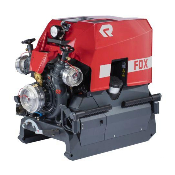
-
Contents
-
Table of Contents
-
Troubleshooting
-
Bookmarks
Quick Links
Operation manual
FOX (4th generation)
Portable fire pump
Item number:
Release:
Language:
Abbreviation:
11033A-003
04/2017 (Rev.02)
English
JWin
Related Manuals for Rosenbauer FOX
Summary of Contents for Rosenbauer FOX
-
Page 1
Operation manual FOX (4th generation) Portable fire pump Item number: 11033A-003 Release: 04/2017 (Rev.02) Language: English Abbreviation: JWin… -
Page 2: Table Of Contents
Table of contents 1 Legal notice ……… 1.1 Copyright .
-
Page 3
7.2.1 Positioning the portable fire pump … . . 7.3 Starting the engine ……7.3.1 Switch on ignition . -
Page 4: Legal Notice
Copyright ORIGINAL OPERATION MANUAL Legal notice Copyright All rights to this manual and its attachments lie with Rosenbauer International AG. The documents are only entrusted to the recipient for their personal use. Reproduction, reprinting (electronically or mechanically), translations in other languages or all other duplication, also of parts of the manual, are only allowed with written permission.
-
Page 5: Declaration Of Conformity
Address: Postbox 176, 4021 Linz, Austria Telephone: +43 (0)732 / 6794-0 that the portable fire pump for fire fighting operations Type FOX portable fire pump (4th generation) Serial number PC116 complies with the following regulations: 2006/42/EC — EC Machinery Directive…
-
Page 6: Introduction
If this manual contains a technical error or a typographical error, Rosenbauer reserves the right to make change at any time and without no- tice. This manual may contains figures and descriptions, that are not built into the delivered product.
-
Page 7: Identification
Introduction Identification Identification Identifying the serial number is important when referring to the manufactur- er in regards to spare parts and technical issues. The serial number of the portable fire pump is located on the operator side, facing away from the area of the engine frame, on the chassis type plate. ►…
-
Page 8: Use Of The Operation Manual
Introduction Use of the operation manual Use of the operation manual 3.4.1 Validity This manual contains information needed for the operation of the product. This manual contains descriptions of special equipment as well as some abstractions and exemplary illustrations. The actual equipping of your prod- uct may therefore differ in part from the descriptions and illustrations.
-
Page 9
Introduction Use of the operation manual Warning notices The safety information warns the user of risk and informs them how these risks can be avoided. Safety information stands at the beginning of a chapter before handling in- structions from which a dangerous situation can occur. Further safety infor- mation is found at the start of this manual. -
Page 10: Safety
Safety Intended use Safety Intended use The portable fire pump: • may only be used in fire fighting operations • may only be used with drinking water and fire fighting water (wastewa- ter- capable) • may only be operated under supervision •…
-
Page 11: Training And Qualifications
Personnel must exhibit physical and mental aptitude. Minors and persons without qualified training may not operate the product. Modifications and conversions to the product may be performed only with written authorisation from Rosenbauer and must be performed by a manu- facturer-authorised person. 11 / 97…
-
Page 12: General Safety Instructions
Observe the operation and maintenance manuals of additional products. If you cannot rectify faults yourself or repairs cannot be performed by spe- cially trained workshop personnel, Rosenbauer or the nearest Rosenbauer service partner must be contacted immediately. 12 / 97…
-
Page 13: List Of Conventional Signs
Safety List of conventional signs List of conventional signs 4.6.1 Meaning of the warning signs Danger from electricity. Impending risk of explosion. Risk from oxidising materials. Risk of harmful or irritating materials. Impending risk of explosion. Impending acid burn risk. Impending hearing damage.
-
Page 14
Safety List of conventional signs Impending crushing risk. Danger from high pressure. Threat of environmental contamination. Impending shearing risk. Impending risk of tripping. Risk of hand injury. 14 / 97… -
Page 15: Meaning Of The Prohibitory Signs
Safety List of conventional signs 4.6.2 Meaning of the prohibitory signs Handling fire and naked flames forbidden! Do not touch or reach in! Do not stay in the danger area! 15 / 97…
-
Page 16: Meaning Of The Caution Signs
Safety List of conventional signs 4.6.3 Meaning of the caution signs Use hearing protection. Wear safety goggles or a safety mask. Wear a protective helmet. Wear protective gloves. Wear a protective suit. Maintain distance. Special caution. Observe environmental protection. 16 / 97…
-
Page 17: Warning Notes
Safety Warning notes Warning notes DANGER! Danger of fatal injury or health hazard due to inhalation of toxic exhaust fumes! Combustion engines working in enclosed areas build toxic exhaust fumes. Is there the need of working in enclosed areas, obey following: Extract the exhaust fumes outside using exhaust hoses.
-
Page 18
Safety Warning notes WARNING! Danger of injury and accidents! Danger of injury and accidents due to malfunctioning or improper used safety devices! Do not override safety and protective devices. Do not manipulate or render safety and protective devices. Check safety and protective devices for proper function. -
Page 19
Safety Warning notes Explosion risk from flammable fuel! When working on fuel systems the fuel may ignite and cause life- threatening injuries.. Do no smoke. Keep fuel away from naked flame. If you are handling fuel keep a fire extinguisher to hand. … -
Page 20
Safety Warning notes Serious injury to persons and damage due to water hammer effect! If water delivery via a pipe or hose is interrupted abruptly, a pressure impact known as the water hammer effect occurs; this is noticeable as a harsh noise (like a hammer hitting a pipe). -
Page 21
Safety Warning notes CAUTION! Danger of injury for the operator due to performing action in wrong order! Individual operating instructions must be done in the prescribed order. Danger of hearing damage due to extended presence in the vicinity of the running pump! Use hearing protection. -
Page 22
Safety Warning notes Injury to persons and material damage due to unexpected releasing of connecting couplings! Before start of operation (pressure), check all connecting couplings with a coupling wrench to ensure tight seating. Water under high pressure! Lingering in front of nozzle discharges could result in serious injuries. Do not linger in front of nozzle discharges. -
Page 23
Safety Warning notes Environmental and health hazard due to lubrication oils! Lubrication, transmission and hydraulic oils can cause permanent water pollution and endanger fauna and flora of all types. Avoid skin contact with hazardous oils. Avoid ground contact with lubrication oils. … -
Page 24
Safety Warning notes NOTICE Damage due to cavitation! The pump capacity is reduced with increasing suction height. When operating with great suction heights, high pump speeds and very high discharge rates, the pump may cavitate. Cavitation causes extreme pressure and temperature peaks which can destroy the pump. Cavitation may sound like marbles are being pumped through the system. -
Page 25: Product Description
The portable fire pump must be supplied from a tank, an open water source or a hydrant. An exact description of the supply takes place in chapter «Op- eration». Designation Assignment of the Rosenbauer designation for the standardized designa- tion. Rosenbauer identification Standardised designation EN1028…
-
Page 26: Engine
Product description Engine Engine The propulsion engine of the portable fire pump is a 3-cylinder, 4-cycle gas- oline engine by Rotax, of type 903 ACE. The engine is a water-cooled alloy engine with 4 valves per cylinder. The cooling water and the lubricating oil is cooled via a closed cooling circuit by means of a water/water and a water/ air heat exchanging device with an electric fan.
-
Page 27: Pump
Product description Pump Pump The single-stage centrifugal pump, consisting essentially of the impeller, main casing and bearing block, is made of a high corrosion resistance light alloy. The pump shaft is of stainless steel. The pump is provided with a cen- tral suction inlet with suction sieve, fixed coupling and blank cap.
-
Page 28: Carrying Frame
Product description Carrying frame Carrying frame The motor-pump unit is fastened to the carrying frame by four elastic rub- ber-metal bearings. Four horizontal, fold-out, rubber-covered handles are integrated into the ends of the carrying frame. The handles can be locked in a longitudinal or perpendicular direction, depending on the carrying meth- od used.
-
Page 29: Priming Pump Professional
Product description Priming pump Professional Priming pump Professional Because centrifugal pumps are not self suction pumps, the required vacu- um is created by an installed priming system. The priming pump is driven by a v-belt and only has to be engaged for the priming process. The priming pump is a manually or automatically controlled double-piston pump, which is made of corrosion-resistant light alloy.
-
Page 30
Product description Priming pump Professional Structure of the priming pump Priming pump Pressure valve plate Suction line Valve cover Suction valve plate Exhaust line Eccentric Main casing 30 / 97… -
Page 31: Technical Description
Technical description Valves and actuators Technical description Valves and actuators X4 X107 X93 X108 Fuel tank cap X107 Beos charging socket (n.v.) Purge valve X108 RLS socket Spindle limit Battery box LCS 2.0 control panel Working light Handle Drain valve Screw-down valve Pressure outlet External drafting connection…
-
Page 32
Technical description Valves and actuators LCS 2.0 control panel S15a S16a S118 Display screen Acknowledge error message Back one screen page Forward one screen page Priming pump S15a Speed adjustment dial S16a Idle speed Ignition on / start the engine Ignition off / shut down the engine S118 Illumination (E11 — Working light, TB1 — Tank filling lighting, TB2 — Support frame… -
Page 33
Technical description Valves and actuators The lower left switch sends the portable fire pump into no-load condition (S16a). With the lower right switch, the lighting (S118) is turned on or off. 33 / 97… -
Page 34: Display Unit Pilot Lamps
Technical description Display unit pilot lamps Display unit pilot lamps Screen page 1 — function displays Page indicator: The page indicator is only for orientation. It indicates the number of pages and highlights the requested page. Pump pressure control (optional): The control display illuminates green when the pump pressure control is ac- tivated, and the actual and target pressure lie within the tolerances.
-
Page 35
Technical description Display unit pilot lamps Pressure ramp: Visualizes the current discharge pressure as a ramp. With activated pump pressure control, the set pressure is displayed as a rising vertical line. Screen page 2 — status displays Fuel tank fluid level: The current fuel tank fluid level is represented by a percentage above the fuel gauge image. -
Page 36
Technical description Display unit pilot lamps Screen page 4 — Service indicators Operating hours: The hours of operation of the portable fire pump are shown next to the im- age display. Software version: The current software version is displayed next to the image display. Service interval hours: The operating hour-dependent service interval is shown next to the picture display. -
Page 37
Technical description Display unit pilot lamps Intake pressure monitoring system warning: If the intake pressure drops below 1.5 bar (incl. tolerance) with intake pres- sure monitoring system active the warning light is activated. The engine speed is then automatically reduced until the intake pressure has risen back to 1.5 bar. -
Page 38: Governor
Technical description Governor Governor The pump pressure or speed are varied with the governor (S15a). Turn the dial clockwise to increase the pump pressure or engine speed. Turn the dial anti-clockwise to decrease the pump pressure or engine speed.
-
Page 39: Optional Equipment
Technical description Optional equipment Optional equipment Exhaust gas hose DANGER! Inhalation of toxic exhaust fumes can cause death or serious damage to health! During operation of internal combustion engines in confined spaces, toxic gases build up. In order to properly discharge the hot exhaust gases, use the provided, standardized exhaust gas hose.
-
Page 40
Technical description Optional equipment Transport wheel set For manoeuvering and for one-man transport, the portable fire pump can be equipped with two transport wheels. Transport wheel set Scope of delivery: • 2 pcs. air-filled tyres • 2 pcs. axle for air-filled tyres •… -
Page 41
Technical description Optional equipment twice a year (depletion or replacement), because conditions for storage (vi- bration, high temperature fluctuations) reduce the knock resistance of the fuel. Fuel cannister Filler neck The filler neck, which is an attachment for the fuel cannister, must always be used when refuelling. -
Page 42
Technical description Optional equipment RLS1000 LED lighting system The RLS1000 light head can be attached by means of optional adapters on the carrying frame. This requires at least two extensions. To ensure operational safety, the RLS1000 can be turned on only when the engine is running and the battery voltage is greater than 11.5 V (see symbol — function indicators RLS illumination). -
Page 43
Technical description Optional equipment 5-key control panel Additional programmable special functions on the portable fire pump can be operated with the keys. • Competition mode • Training • Competition • Pressure preselection keys (only in conjunction with pump pressure governor option) •… -
Page 44
Technical description Optional equipment Please refer to a separate document for information on operating the other varieties. If the discharge pressure should be limited, either the speed is to be re- duced via governor, or the pump pressure governor is to be activated via the pressure preselection keys with a fixed discharge pressure. -
Page 45: Operation
Operation Preparation for initial operation Operation Preparation for initial operation The sequence of the described processes is to be maintained without ex- ception! Before initial start-up, check the correct fluid level of all consumables. ► Oil in priming pump. For further information refer to Chapter «Priming pump» …
-
Page 46: Preparation For Start-Up
Operation Preparation for start-up Preparation for start-up WARNING! Potentially fatal injuries due to the engine taking in flammable gases! Do not operate the engine in areas with a heavy concentration of flammable vapors such as e. g. diesel, gas or propane. When handling flammable liquids and gases, always shut off the …
-
Page 47: Starting The Engine
Operation Starting the engine Starting the engine WARNING! Potentially fatal injuries due to the engine taking in flammable gases! Do not operate the engine in areas with a heavy concentration of flammable vapors such as e. g. diesel, gas or propane. When handling flammable liquids and gases, always shut off the …
-
Page 48: Switch On Ignition
Operation Starting the engine NOTICE Unplanned event The portable fire pump can be controlled at all times, even in critical operating states (e.g. burst hose). The approach depends on the situation and is the operator’s responsibility. Variety1: ► Press S16 a Idlefunction switch. The speed of the portable fire pump is automatically reduced to …
-
Page 49
Operation Starting the engine NOTICE Starting without control panel is switched on For a shortened start procedure, by a continuous actuation (approx. 5 sec.) of the Engine start function switch (S57) the portable fire pump can be put into operation. The portable fire pump is then operated with a predefined speed of 1700 min-1. -
Page 50: Priming From An Open Water Source
Operation Priming from an open water source Priming from an open water source NOTICE Damage due to cavitation! The pump capacity is reduced with increasing suction height. When operating with great suction heights, high pump speeds and very high discharge rates, the pump may cavitate. Cavitation causes extreme pressure and temperature peaks which can destroy the pump.
-
Page 51: Activate Drafting Operation From Open Water Source
Operation Priming from an open water source 7.4.1 Activate drafting operation from open water source ► Bring the portable fire pump into a good position in relation to the water source. Observe the inclination of the engine (max. 35° in the direction of …
-
Page 52: Hydrant Operation
Operation Hydrant operation Hydrant operation NOTICE Damage to the pump system due to use of contaminated water! Contaminated water can cause damage to the pump due to deposits. Before connecting the pressure hoses to the hydrant, open the hydrant and allow water to escape until only clean water flows.
-
Page 53
Operation Hydrant operation Pumping NOTICE Do not operate the pump in the cavitation area! Cavitating of the pump is perceptible as a noise (similar to pebbles being pumped). Never operate the portable fire pump without suction head or suction filter. -
Page 54: Monitoring During Operation
Operation Monitoring during operation Monitoring during operation The LCS (Logic Control System) monitors: • engine starting/stopping, speed adjustment, • fuel capacity, cooling water temperature, oil pressure, etc. ► The speed of the engine can be changed using the governor (S15a). Optionally once this is reached, it is saved by pressing the governor (S15a).
-
Page 55: Switching Off The Engine
Operation Switching off the engine Switching off the engine At high ambient temperatures (> 35°C) and an engine temperature of above 95°C allow the engine too cool down before switching it off in oper- ation. To do this operate the portable fire pump at approx. 2000-2500 min-1 in suction state (higher cooling performance) for approx.
-
Page 56
Operation Switching off the engine Disconnect the suction hoses before releasing the pressure from the riser pipes. The maximum pressure for suction hoses is 3 bar. After operating the pump with salt water or dirty water, the pump must be flushed with clean water! 56 / 97… -
Page 57: Flush/Drain
Operation Flush/drain Flush/drain A thorough flushing with seawater or dirty water is to be carried out after each operation. If seawater or dirty water was sucked up with the priming pump, it is import- ant to rinse with clean water to prevent damage to the piston. After rinsing, the entire portable fire pump must be drained.
-
Page 58: Transporting The Portable Fire Pump
Operation Transporting the portable fire pump Transporting the portable fire pump CAUTION! Risk of injury to operating personnel during transport Unfolded handles represent a tripping hazard! Fold the unfolded handles after use. If possible, always carry with 4 people and lift from the knees to reduce the risk of back injuries.
-
Page 59: Transport By Means Of The Transport Wheels (Optional)
Operation Transporting the portable fire pump 7.9.2 Transport by means of the transport wheels (optional) For manoeuvering and for one-man transport, the portable fire pump can be equipped with two transport wheels. The carrying handles are swung in the direction of travel. The portable fire pump can then be lifted and moved by an operator.
-
Page 60: 7.10 Tilting The Engine Cover
Operation Tilting the engine cover 7.10 Tilting the engine cover CAUTION! Danger of burning! Do not grip onto switched-on or recently switched-off search lights. There is a danger of crushing when closing the engine cover! Only touch the engine cover where appropriate (EC1). …
-
Page 61: 7.11 Fuelling And Refuelling
Operation Fuelling and refuelling: 7.11 Fuelling and refuelling: To perform a safe refuelling operation, it is essential to comply with all se- curity measures. WARNING! Risk of fire and explosion! When refuelling with a fuel canister, the filler neck must always be …
-
Page 62: Fuelling Operation When Engine Is Running
Operation Fuelling and refuelling: Limited shelf life of fuel The fuel in the tank of the portable fire pump must be utilised within six months. Otherwise deposits (sediments and precipitation) can occur. The fuel in the fuel canister is to be changed at least twice a year …
-
Page 63
Operation Fuelling and refuelling: Refuelling: ► Prepare the fuel canister as shown (opened and with filler neck fitted correctly). ► Ensure that no ambience disturbances can arise. ► Ensure secure footing during refuelling (e.g. spillages — hot surfaces — engine). ►… -
Page 64: Servicing And Cleaning
Only technology which is regularly maintained by specialists can meet the high demands. Rosenbauer service partners will gladly provide you with comprehensive advice about inspections and Service PLUS, as well as about the exact scope and costs of testing and maintenance work.
-
Page 65
Servicing and cleaning Engine component overview Type plate Camshaft sensor Thermostat housing Water pump housing Oil-water heat exchanger Oil filter housing Oil pressure regulator 65 / 97… -
Page 66
Servicing and cleaning Engine component overview Throttle valve joints Pressure and temperature sensor Airbox Engine speed sensor Control device Crankcase ventilation 66 / 97… -
Page 67
Servicing and cleaning Engine component overview Ignition coil E-Starter Fuel distributor Oil pressure switch 67 / 97… -
Page 68: Service Plan
Servicing and cleaning Service plan Service plan 8.2.1 Oil change interval Symbol Work specification Priming pump ● ● ● Engine ● ● ● ● a. Whichever comes first b. Whichever comes first c. one-off fuel change after the first 10 operating hours 8.2.2 Inspection procedures Symbol…
-
Page 69: Checking For Signs Of Leakage
Servicing and cleaning Service plan Symbol Work specification Check the coolant in the en- ● ● ● gine V-belt of the priming pump ● ● check air filter ● ● ● 8.2.3 Checking for signs of leakage Symbol Work specification Priming pump ●…
-
Page 70: Lubrication Service
Servicing and cleaning Service plan 8.2.4 Lubrication service Symbol Work specification Carrying handles ● ● Shaft of pressure valves ● ● 70 / 97…
-
Page 71: Lubrication Chart
Servicing and cleaning Lubrication chart Lubrication chart Description Medium Dosing Unit Engine oil SAE Engine oil Litres 15W40 Priming pump 0.65 (0.17) (gal- API/SF lons) MIL-L-46152 B Ford M2C-9011 GM 6048 M 5W40 engine oil — fully synthetic Engine 2 — 2.5 l Litres 4-stroke engine VOLVO VCS…
-
Page 72: Inspection Procedures
Servicing and cleaning Inspection procedures Inspection procedures Testing and inspection procedures Assessment and inspection work may only be carried out by correspond- ingly trained fire-fighting personnel, who are familiar with the portable fire pump. The work must be carried out regularly, especially after each use, to ensure optimum operational safety of the portable fire pump.
-
Page 73
Servicing and cleaning Inspection procedures Priming pump All moving parts are oil-bath lubricated. Oil filler plug Oil drain plug Oil level sight glass Check oil level: ► Check the oil level of the priming pump with the sight glass. The oil level must be between the top and bottom markings. … -
Page 74
Servicing and cleaning Inspection procedures Engine coolant inspection ► Remove the pressure cap from the compensation tank at room tem- perature. The coolant should be between the MIN and MAX markings in the compensation tank. ► If necessary, fill the tank with coolant and fit the pressure cap. Use VOLVO VCS coolant for the initial filling. -
Page 75
Servicing and cleaning Inspection procedures Change air filter The air filter of the portable fire pump engine should be replaced every 5 years. When using in regions with specially heavy dust loads the change, may take place earlier, depending on the contamination. ►… -
Page 76
Servicing and cleaning Inspection procedures Fuses and relays The electrical circuits on the electrical unit of the portable fire pump are se- cured with fuses. The fuse holder is located on the side away from the operator, behind the air filter box The fuse holder is located on the side opposite the operator, behind the air filter box Before replacing the burnt out fuse, check the cause of the defect. -
Page 77
Servicing and cleaning Inspection procedures Calibrate pressure sensors The pressure sensors built into the portable fire pump are absolute pres- sure sensors and are therefore subject to fluctuations in the atmosphere air pressure (high difference, weather conditions etc.). Before calibrating the pressure sensors ensure that the portable fire pump is in a depressurised state (drain valve J7 and screw-down valves J10 open, engine not started). -
Page 78: Service Procedures
Servicing and cleaning Service procedures Service procedures Service work is work that may only be carried out by specially authorised expert personnel. This work is to be carried out or allowed to be carried out in accordance with the manufacturer’s regulations. Maintain service intervals, as well as officially prescribed testing schedules and create written records for them.
-
Page 79
Servicing and cleaning Service procedures Top up oil ► Open oil filler plug ► Add oil using a suitable funnel and wait until it has run down. Oil quality and oil filling quantity, refer to chapter «Lubrication chart». ► Check that the oil level is between the MIN and MAX markings. -
Page 80
Servicing and cleaning Service procedures ► Completely screw on oil drain hose and drain oil. ► Collect the old oil and dispose of it properly. ► After approx. 1.7l used oil has flowed out, the 3 fastening screws (1) are opened on the oil filter housing (M11) and the oil filter (4) removed. Oil is drained. -
Page 81
Repeat process untilo 2.5 — 2.7 l of coolant is in the cooling circuit. If after three-times of repetition still the required 2.5 — 2.7 l is not in the cooling circuit, contact Rosenbauer customer service or the nearest Rosenbauer service centre. -
Page 82
Servicing and cleaning Service procedures Check valve plates of the priming pump Valve cover Valve plate To guarantee the full function of the priming pump, the valve plates must be checked for contamination and damage and replaced, if required, in the event of reduced performance. -
Page 83
Servicing and cleaning Service procedures Check valve plates after the installation ► Place steel ruler on the top of the valve cover. The ruler must be ap- plied on both sides of the cover. ► There must be a gap between the ruler and the mounting part, in the middle. -
Page 84: General Guidelines For Handling Electronic Components
Servicing and cleaning Service procedures 8.6.1 General guidelines for handling electronic components NOTICE Neglecting these recommendations will result in loss of warranty. Working on vehicles fitted with electronic devices Installation and measurement of electronic devices. ► Ensure power is switched off before working on electrical parts (except when measuring).
-
Page 85
Servicing and cleaning Service procedures Painting work or working with chemicals or aggressive substances: NOTICE Damage to electronic components Due to high temperature in a paint box, electronics can be severely damaged. Expose electronics to max. 95 °C (203 °F) for a short period. … -
Page 86: Storage And Transport
Servicing and cleaning Service procedures 8.6.2 Storage and transport The portable fire pump and the corresponding installation material must be stored and transported in its packaging. It must be handled carefully and cautiously. Preserving and storing If the portable fire pump is not operated for a longer period of time (> 3 months) the following advice must be observed.
-
Page 87: Troubleshooting
Troubleshooting Faults and their solutions — pump Troubleshooting Faults and their solutions — pump The following list offers an overview of possible faults on the pump. The list is not complete, but in the event of a malfunction it can be helpful in local- ising and rectifying the fault.
-
Page 88: Faults And Their Solutions — Engine
Faults and their solutions — engine If problems or repairs can not be clearly identified or solved please contact the customer service department or your Rosenbauer representative. Faults and their solutions — engine The following list offers an overview of possible faults on the engine. The list is not complete, but in the event of a malfunction it can be helpful in lo- calising and rectifying the fault.
-
Page 89
Spark plug electrode gap too Measure electrode gap. If the electrode large gap is outside the tolerance, replace spark plugs. If problems or repairs can not be clearly identified or solved please contact the customer service department or your Rosenbauer representative. 89 / 97… -
Page 90: Environmental Protection
Environmental protection Disposal of hazardous substances Environmental protection 10.1 Disposal of hazardous substances Dispose of all materials and old parts that are produced through the han- dling and repair of this unit in an environmentally sound way. Disposal of used oil, cooling water and fuels Used oil, cooling water and fuels are water-polluting substances.
-
Page 91: Technical Data
Technical data Disposal of hazardous substances Technical data Pump Manufacturer Rosenbauer International AG Type PFPN 10-1000 PFPN 10-1500 DIN EN 14466 Number of stages Single-stage centrifugal pump Nominal discharge 1500 l/min Nominal supply pressure 10 bar Geodetic nominal suction height…
-
Page 92
Technical data Disposal of hazardous substances Engine Consumption approx. 14 l (at a constant 1500 l/ min at 10 bar (5200 min-1)) approx. 18 l (at a constant 1000 l/ at 15 bar (6000 min-1)) Engine control BOSCH ME17 Ignition system Electronic ignition system, ignition programme Spark plug… -
Page 93: 11.1 Noise Measurements
Technical data Noise measurements Unit Dry weight approx. 150 kg (without fluids) Operating weight approx. 166 kg (full 20 l tank) Dimensions (L x W x H) approx. 923 x 636 x 845 Volume approx. 0.498 m³ Operating range -15 °C to +35 °C ambient tempera- ture (EN14466) 11.1 Noise measurements PFPN 10 — 1000…
-
Page 94
Technical data Noise measurements PFPN 10-1500 performance chart • Flow rate [l/min] • Total head discharge [bar] 94 / 97… -
Page 95: List Of Spare Parts
12.1 List of spare parts Access to the online spare parts catalogue for the portable fire pump is pro- vided under the following link. https://spareparts.rosenbauer.com/template/index.php User name: PC11X Password: PC11X When logging in make sure you check for capitals and lower case.
-
Page 96: List Of Abbreviations
List of abbreviations List of abbreviations Fire fighting specific abbreviations Power take off Normal pressure High pressure AFFF Aqueous film forming foam Piston priming pump, priming pump Aluminium technology O-stream nozzle Portable pump UHPS Ultra high pressure system Plastics and drinking water DVGW German Association of Gas &…
-
Page 97
List of abbreviations General abbreviations lbs/s Pounds per second Feet Gallons per minute 97 / 97…