-
Contents
-
Table of Contents
-
Troubleshooting
-
Bookmarks
Quick Links
SMARTFIND GMDSS NAVTEX
USER & INSTALLATION MANUAL
GMDSS TRI-CHANNEL
NAVTEX RECEIVER
VESSEL IDENTIFICATION INFORMATION
Name
Call Sign
MMSI
SMARTFIND GMDSS
NAVTEX S/N
Antenna Type
RX frequencies
518 kHz
supported by antenna
490 kHz
4209.5 kHz
2015 Orolia Ltd
Part No: 93-204
Disclaimer
The information and illustrations contained in this publication are to the best of our
knowledge correct at the time of going to print. We reserve the right to change
specifications, equipment, installation and maintenance instructions without notice as
part of our policy of continuous product development and improvement. No part of this
publication may be reproduced, stored in a retrieval system or transmitted in any form,
electronic or otherwise without permission in writing from Orolia Ltd. No liability can be
accepted for any inaccuracies or omissions in the publication, although every care
has been taken to make it as complete and accurate as possible.
Summary of Contents for mcmurdo SMARTFIND GMDSS NAVTEX

ICS NAV5plus
GMDSS NAVTEX Receiver
User Guide

VESSEL IDENTIFICATION INFORMATION
Name
Call Sign
MMSI
ICS NAV5plus S/N
RX frequencies 518 kHz
490 kHz
The technical data, information and illustrations contained in this publication were to
the best of our knowledge correct at the time of going to print. We reserve the right
to change specifications, equipment, installation and maintenance instructions
without notice as part of our policy of continuous product development and
improvement. No part of this publication may be reproduced, stored in a retrieval
system or transmitted in any form, electronic or otherwise without permission in
writing from McMurdo Limited. No liability can be accepted for any inaccuracies or
omissions in the publication, although every care has been taken to make it as
complete and accurate as possible.
Safety Warnings
This instrument is for use as an aid to sailors and should not lead to a
reduction in the level of good seamanship required at all times.
Reception of messages cannot always be guaranteed as this depends
on local radio propagation.
Contents
Quick Start ………………………………………………………………………………………. 1
Introduction ……………………………………………………………………………………… 1
How To Operate Your ICS NAV5plus………………………………………………….. 3
System Alarms…………………………………………………………………………………. 8
Serial Output……………………………………………………………………………………. 9
Tearing off a Printout ………………………………………………………………………. 11
Paper Loading………………………………………………………………………………… 11
Installation……………………………………………………………………………………… 14
Self Test………………………………………………………………………………………… 24
Troubleshooting Guide ……………………………………………………………………. 26
Warranty ……………………………………………………………………………………….. 29
Options………………………………………………………………………………………….. 30
Specifications…………………………………………………………………………………. 31
Appendix II: Message Type Indicators ………………………………………………. 36
Appendix III: Declaration of Conformity ……………………………………………… 37
Please take the time to read this manual carefully. It contains some
essential information regarding the operation and maintenance of the
product and a useful background to the NAVTEX system.
We recommend that you regularly visit the McMurdo website
www.mcmurdo.co.uk for information on updates, the availability of software
enhancements, further options and support. The support pages contain
frequently asked questions about the ICS NAV5plus that you may find
useful. There is also a NAVTEX database providing a list of operational
NAVTEX stations and their details.
The IMO and various national coastguards also operate informative
websites that you may wish to visit, see the links page at
www.mcmurdo.co.uk.
1
QUICK START
You will find this product extremely easy to operate.
• Follow the installation guidelines
• Re-check the cable connections
• Apply power
• Switch on the ICS NAV5plus
• The ICS NAV5plus will now print NAVTEX messages
INTRODUCTION
NAVTEX is a method of transmitting navigational warnings and weather
forecasts from designated coast radio stations. All English language
transmissions are made on 518 kHz. Each station is allocated several time
‘slots’ during the day, when it is permitted to transmit; these are normally at
four hourly intervals. The only exceptions to this are gale warnings and
search and rescue messages, which may be transmitted at any time.
Reception of NAVTEX is normally limited to an area of 200 — 300 miles
radius around each transmitting station, although considerably greater
ranges are possible at night.
Subject to IMO approval, additional local language transmissions may be
made on 490 kHz.
The ICS NAV5plus has been designed to the latest European and
International specifications to provide up to date weather and navigation
warning information to commercial vessels. It meets IMO requirements
under GMDSS and is designed for simplicity of operation. It will provide
reliable printed information day after day within designated NAVTEX
coverage areas.
2
Installation is straightforward. Connect the ICS NAV5plus to a 12 or 24 volt
DC supply and connect a suitable antenna. Switch it on, and it will start
printing NAVTEX messages without further manual intervention. Note that if
there are only a couple of NAVTEX stations within range it may be several
hours before you receive the first message
If all stations and message types are left selected, the ICS NAV5plus may
overwhelm you with information. It can therefore be set up to print only
those stations and message categories you want to receive and which are
applicable to the area in which you are sailing.
Normally, routine messages are repeated at four hourly intervals. Provided
that the ICS NAV5plus is left running, repeated messages are not printed
again. The suppression of repeated messages stops three days (72 hours)
after the last transmission of the message.
Permanent installation of the ICS NAV5plus can be made with the
bulkhead-mounting bracket provided. Alternatively, the optional FMT-2
flush panel mounting kit, part number 913-24, may be purchased.
A NAVTEX antenna should be mounted where it is elevated clear of metal
objects in a location where it cannot easily be damaged.
Please read the installation section of the user guide thoroughly
before attempting installation of the ICS NAV5plus.

3
HOW TO OPERATE YOUR ICS NAV5PLUS
Initial Operation
Switch on the ICS NAV5plus by pressing the power button
The LCD display backlight will come on.
The LCD data display will show :
The “V2.07” is the software version, which may vary.
A short self-test is performed, then the ICS NAV5plus is ready to receive
NAVTEX messages.
The factory default setting is for all NAVTEX stations and message
categories to be printed.
To change the settings, refer to the SETUP section.
ICS NAV-5 V2.07
LOG EMPTY
4
SETUP
Setup Controls
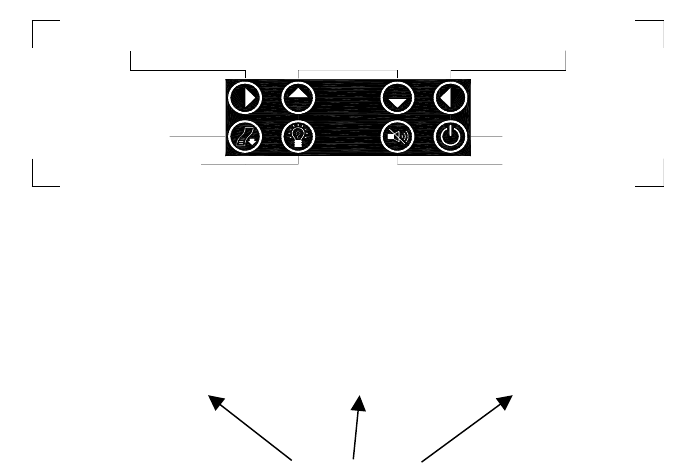
The diagram shows the main functions of the front panel controls:
NAVTEX Message Type Selection
At the beginning of each NAVTEX message there is a message header
which identifies the source and nature of message using an identity code.
For example GA59 :-
Station Message category Serial No.
G A 59
This identifies which station has transmitted the message and the nature of
the message.
It is possible to select the NAVTEX stations you wish to receive messages
from and to restrict certain message categories.
DIM (backlighting)
PAPER FEED
Start programming Select or de-select Finish programming
stations / messages
POWER ON / OFF
STOP ALARM

5
DUAL CHANNEL OPERATION
The ICS NAV5plus is a dual channel receiver.
The and keys on the keypad are used to switch the LCD display
between RX-A (the standard 518 kHz receiver) and RX-B (the 490 kHz
second receiver ).
The LAST MSG display shows the identity number of the last message
received on that receiver and the two-dot signal indicator will flash if there is
a signal being received from that receiver.
• Pressing and will display the corresponding information for the
other receiver.
Notes:
Although the and keys are used to select which receiver is shown
on the display, it is important to realise that both receivers are actively
receiving signals all the time.
If messages are being transmitted at the same time on both channels, both
messages will be received and printed.
Messages from RX-B are identified separately on the printout.
Only messages from the 518 kHz receiver channel will be present on the
RS422 serial output.
6
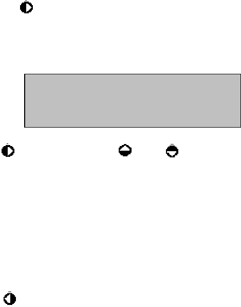
NAVTEX Stations Setup Procedure
When the key is pressed, the set up mode for the selected receiver will
be started. This enables the stations and message types required for that
receiver to be set. The two receivers are set up independently.
Station selection is displayed first:
Press followed by either the or the buttons, one push of either
button will select, a second push will deselect.
Deselected stations are indicated by a ‘dash’ (–).
Each NAVTEX transmitting station has its own identifying letter. A list of
these can be found in the NAVTEX Station Designations table section of
this manual (Appendix 1).
If you do not know which stations cover your area, start by leaving them all
stations selected. You will soon find which stations are relevant to you.
Press to store the NAVTEX station and message category selections.
STN: ABCDEFGHIJ
KLMNOP
RSTUVWX
7
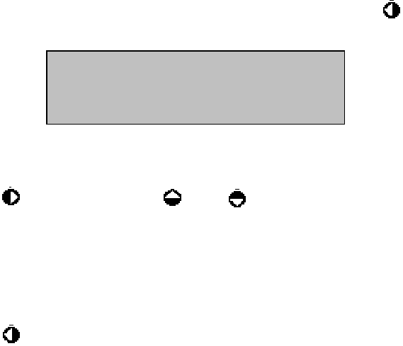
NAVTEX Message Category Setup Procedure
• Once you have completed the NAVTEX station selection, press to
change to the message category selection screen:
Message categories are identified by a single letter.
Press followed by either the or the buttons; one push of either
button will select, a second push will deselect.
Deselected message categories are indicated by a ‘dash’ (–).
• Message categories, A, B, D and L cannot be deselected.
Press to store the NAVTEX station and message category selections.
For a table of NAVTEX message categories, see APPENDIX II.
MSG: ABCDEFGHIJ
KLMNOP
RSTUVWXYZ

8
SYSTEM ALARMS
Audible Alarms
The alarm signal within the ICS NAV5plus will sound under the following
circumstances:—
• INCORRECT KEY PRESSED
• PAPER OUT
• LOW BATTERY ( Power supply voltage is less than 9V DC)
• VITAL NAVTEX MESSAGE
Remove the cause of the alarm and then press the key to stop the
alarm.
Visible Alarms
The visible alarms will show on the LCD under the following
circumstances:—
• PAPER OUT
• LOW BATTERY ( Power supply voltage is less than 9V DC)
• VITAL NAVTEX MESSAGE
Remove the cause of the alarm and then press the key to stop the
alarm.
9
SERIAL OUTPUT
The ICS NAV5plus has an EIA RS422A-compatible serial output which can
be used to connect the ICS NAV5plus to other equipment such as an
integrated bridge system or a PC running charting software.
The serial output operates all the time that the ICS NAV5plus is switched on
– there is no ON/OFF control for the serial output.
All correctly received NAVTEX messages from the 518 kHz receiver are
sent to the serial output. The station and message category settings for
printing within the ICS NAV5plus are ignored.
It is anticipated that the external equipment (e.g. a PC running charting
software) will have its own method of selecting stations and message
categories and as such ALL NAVTEX messages received by the ICS
NAV5plus will be output.
Note: Only messages from the 518 kHz receiver channel will be present on
the RS422 serial output.
Connecting to the Serial Output
Main Connector
Pin Function
3 EIA-RS-422-A Output (TxA)
4 EIA-RS-422-A Output (TxB)
The RS422 output is ‘simplex’ which means that multiple receivers can be
connected to the ICS NAV5plus but the ICS NAV5plus is the only
transmitter.
The RS422 standard for connecting equipments specify that, for a short
cable with only one receiver, the cable may be unterminated. For longer
cables (20 metres or more) or installations with multiple receivers, a
termination resistor should be fitted at the far end of the cable run from the
ICS NAV5plus. The resistor value should be the ‘characteristic impedance’
of the cable, which typically is 100 to 120ohms. A ¼ W resistor is sufficient.
The cable used should be twisted pair 7/0.2 mm or similar.
10
Configuring the RS422 Receiver
The receiving device (a PC running charting software, or similar) needs to
be configured so that it can receive the NAVTEX messages output from the
ICS NAV5plus. Set up the RS422 receiver’s communication port as:
Baud rate 4800
8 data bits
1 stop bit
no parity
XON/XOFF
Connecting to an RS422 Device
If the receiver is an RS422 device then only 2 connections are required:
Pin ICS NAV5plus
Connection RS422 Receiver Connection
3 Output (Y) Input (A)
4 Output (Z) Input (B)
Note that, because receiver terminology varies between manufacturers, it
may be necessary to swap the two connections for the receiver to function
correctly. Don’t worry – you won’t damage the interface.
Connecting to a RS232 Device
If the receiver is a RS232 device, eg a computer serial (COM) port, then a
RS422 to RS232 converter is required.
A suitable converter is Amplicon ‘Model 485F9/485H9’, although any similar
product should be compatible. Be sure to follow the connection instructions
supplied with your converter.

11
TEARING OFF A PRINTOUT
Use a gentle up or downward and sideways motion to tear the paper at the
exit point of the ICS NAV5plus case.
Warning: DO NOT PULL THE PAPER THROUGH THE PRINTER AS
THIS ACTION MAY DAMAGE THE PRINTER MECHANISM
Always use the paper feed button to feed the paper clear of the
mechanism.
PAPER LOADING
The ICS NAV5plus is supplied with one roll of paper fitted. At the end of this
paper roll the ICS NAV5plus will sound an alarm and printing will stop.
Early warning that the paper is about to run out is given by red stripes on
the paper.
Should the paper run out in the middle of a message, information will not be
lost provided that the ICS NAV5plus is not switched off whilst the paper roll
is replaced.
Ensure that proper anti-static procedures are applied when installing or
servicing the ICS NAV5plus and also when replacing the paper roll. Take
care to discharge any static that you may be carrying by touching exposed
metalwork on the case prior to replacing the paper roll.
• To remove the remaining paper, open the paper loading door. Push a
top corner of the door to release the locking door catch
• Tear off the paper where it enters the printer mechanism
• Remove the old paper roll
• Remove the plastic spindle from inside the paper roll
• Press the paper feed button to feed the remaining paper through
the printer mechanism
Warning: DO NOT PULL THE PAPER THROUGH THE PRINTER AS
THIS ACTION MAY DAMAGE THE PRINTER MECHANISM
12
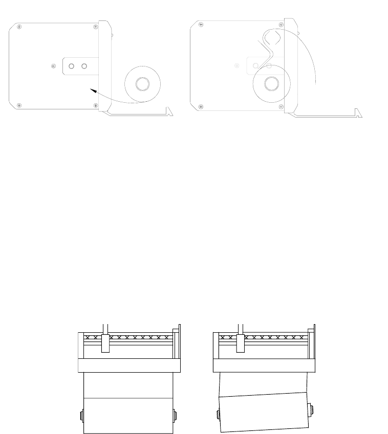
• Place the new roll onto the spindle with the paper emerging from the
top of the roll pointing towards you
• Mount the new roll and spindle onto the roll bracket
• Insert the paper into the slot at the base of the printer mechanism, and
feed it in as far as it will go
It is important that the edge of the new paper roll is cut straight and
that the paper is dry. Use scissors to prepare a clean straight paper
edge.
• Check that the paper is inserted so that the heat sensitive surface is
uppermost as the paper exits the printer
• Check that the paper roll is correctly aligned with the print mechanism
as shown below
CORRECT INCORRECT

13
Press the paper feed button until the paper appears through the door
exit
New supplies of paper rolls can be ordered from McMurdo dealers, or
contact McMurdo Tel +44 (0) 23 9262 3900 Fax +44 (0) 23 9262 3999,
Email sales@mcmurdo.co.uk.
Quote order code: NAVTEX Rolls.
This specifies a box of eight rolls of paper.
The paper roll size is 80mm x 20m with a maximum diameter of 42mm and
an internal spindle (hole) diameter of 12mm.
An updated list of McMurdo distributors is available on the McMurdo
website (www.mcmurdo.co.uk) Distributors page
14
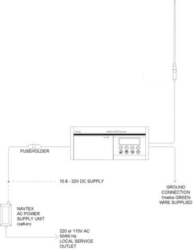
INSTALLATION
ICS NAV5plus System Overview
NAVTEX
ANTENNA
15
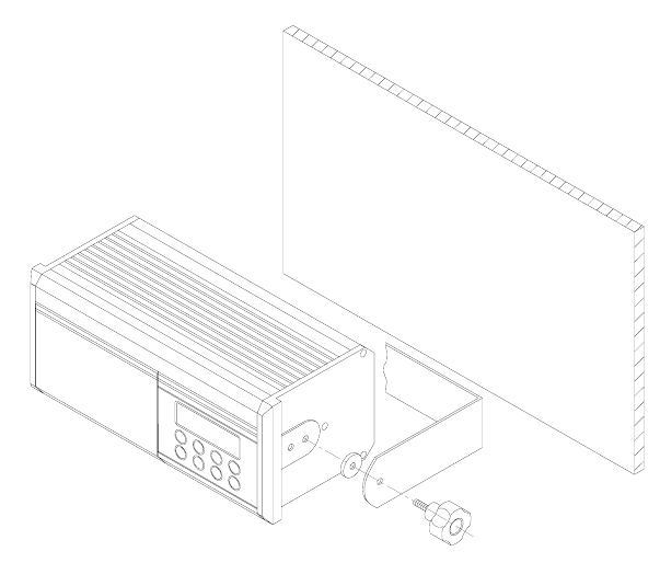
Mechanical Mounting using U-Bracket Supplied
The standard bulkhead mounting U-Bracket can be used to mount the ICS
NAV5plus above or below a horizontal (or near horizontal) surface.
• Use the U-bracket as a template to mark out the 4 fixing holes on
the mounting surface.
• Drill 4 off fixing pilot holes (1/8 inch / 2.5 mm diameter for
hardwood, or 3/32 inch / 3mm diameter for softwood or plywood).
• Use the No.10 S/S pozidrive screws supplied to attach the U-
Bracket to the mounting surface.
• Use the two 25 mm diameter rubber washers supplied between the
U-Bracket and the ICS NAV5plus case.
• Make the necessary electrical connections to the rear of the ICS
NAV5plus.
• Ensure that the two handwheel knobs are inserted through the
bracket and rubber washers on each end of the ICS NAV5plus.
• Hand tighten the knobs.
16
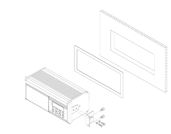
Mechanical Mounting using the Optional Flush Mount Kit
If the ICS NAV5plus is to be mounted through a flat panel, it is advised that
you purchase the FMT-2 flush mounting kit option, part 913-24.
Full fitting instructions are included in the FMT-2 flush mounting kit.
Warning: Do not mount the ICS NAV5plus in a position where sea spray
can reach it, or where it may be exposed to direct sunlight

17
Electrical Connections
A connection must be made to a 12 or 24 V DC supply via a circuit breaker
capable of supplying at least 2 amps. Connection should be to the ships
radio battery and be in accordance with GMDSS requirements.
• Connections are made directly to the screw terminals on the ICS
NAV5plus mating connector at the rear of the unit using the 1m length
cable provided.
• Use cable ties to restrain the wiring, and so prevent it becoming
weakened by vibration. The connecting cables should be restrained by
securing them to the rear of the ICS NAV5plus bracket, or to adjacent
metalwork.
Safety Warning
The ICS NAV5plus has been designed and manufactured to be
completely safe when used in accordance with the instructions
given in this manual. To ensure that the complete installation is
safe, it is essential that a fuse or circuit breaker is installed in the
supply cable as described in the Installation Section of this
manual.
The ICS NAV5plus is supplied with a DC power cable and an in-
line Type ‘T’ 2.5 amp fuse. It is essential that this fuse is included
in the installation.
To ensure the best possible protection of the ICS NAV5plus from
static electricity or nearby lighting strikes, the pre-fitted green
grounding wire (connected to the safety earth stud) must be
connected to a nearby (hull) electrical grounding point.
18
Interface Connections
ICS NAV5plus rear panel connections:
Main Connector
Pin Function
1 Not used
2 Not used
3 EIA-RS-422-A Output (Y)
4 EIA-RS-422-A Output (Z)
5 Not used
6 Not used
7 Power input (negative)
8 Power input (positive)
9 N/O Alarm contact (2 A max @ 24 V DC)
10 N/O Alarm contact (2 A max @ 24 V DC)
Antenna Connector
Pin Function
1 Active antenna input*
2 Active antenna screen
3 Safety ground
4 Antenna ground
5 Passive antenna screen
6 Passive antenna input
* WARNING: DC voltage is present on Pin 1
NOTES:
For each connector, Pin 1 is on the right, looking at the rear of the ICS
NAV5plus.
• The auxiliary alarm contact is capable of switching up to 24 V DC at up
to 2 A. The contacts are not connected to any internal voltages
• The power supply input is isolated from the case and antenna. It must
remain within the range 10.8 – 32 V DC at all times.
19
Selecting a Suitable Antenna
The ICS NAV5plus receives transmissions on two frequencies. 518 kHz
transmissions are in International English; 490 kHz tranmissions may be in
a local language.
To receive on both frequencies the ICS NAV5plus must be used with a
broadband antenna that covers both 518 kHz and 490 kHz.
Only one antenna can be connected to the ICS NAV5plus, either to the
passive antenna input or to the active antenna input.
Several different antenna types are recommended for the ICS NAV5plus.
The best option will depend upon the receive frequencies required and the
ease of installation.
Choice of Antenna
Antenna 490 kHz 518 kHz
ANT/w 99
NAV-ANT/w * 99
NAV-ACTIVE * 99
Whip antenna with 50 ohm match 99
Long wire with 50 ohm match 99
* recommended options
The ICS NAV5plus must be used with a low impedance 50 Ω antenna
or an antenna with a 50 Ω matching network.
A ‘mis-matched’ or ‘high impedance’ whip or wire antenna should not be
used or the operational range of NAVTEX reception will be greatly reduced.
• If a ‘Wire’ or ‘long whip’ antenna is used with the ICS NAV5plus it must
be fitted with a 50 Ω matching transformer.
20
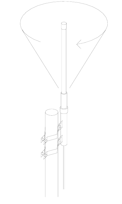
Important
NAVTEX antennas must be mounted clear of obstructions and at least
0.5 metres away from other antennas.
Ensure that they cannot be snagged by mooring warps or running
rigging or engulfed by green water.
Antennas should always be mounted vertically.
Installation of a NAVTEX Antenna
The NAVTEX antenna should be mounted vertically, in an elevated
position. Metal, rigging or other antennas must not be located in the ‘NO
GO cone’ surrounding the upper part.
Keep this area clear
21
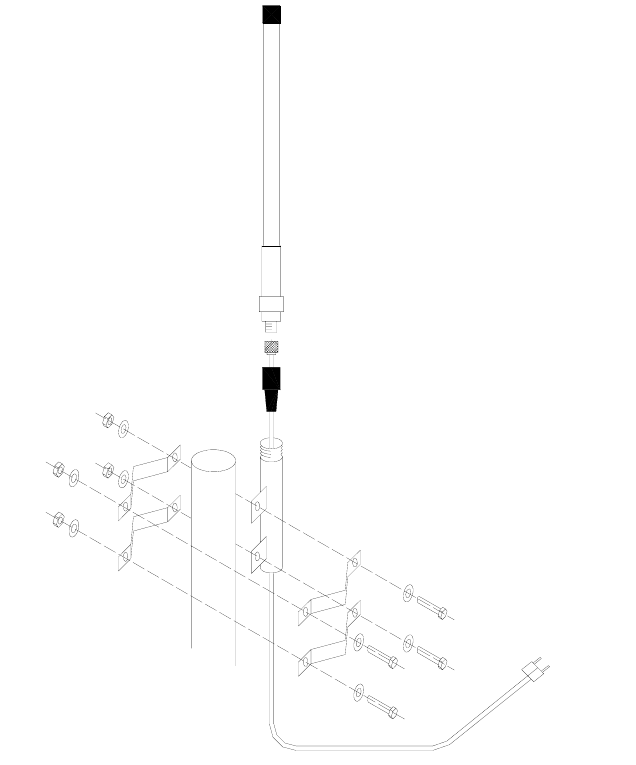
Installation procedure: NAV-ANT/w & NAV-ACTIVE, NAV-
CABLE, NAV-CLAMP/a
Start the antenna cable installation from the ICS NAV5plus (lower) end first.
Where the cable passes through bulkheads or decks, waterproof deck
glands should be installed. Securely fasten the cable against vibration using
plastic cable tie wraps.
Typical installation of
NAV-ANT/w, NAV-CLAMP/a and
NAV-CABLE
Typical installation of
NAV-ACTIVE or NAV-ANT/w,
NAV-CLAMP/a and NAV-CABLE
22
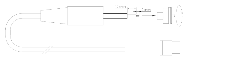
Antenna connection
Pass the cable though the black plastic boot and prepare the end of the
cable as shown in the diagram, folding the cable braid back and screwing
the PL259 connector firmly in place. To ensure a good connection it is
recommended that the centre pin is soldered.
Screw firmly in place
Solder centre pin connection
Side pin (2)
Centre pin (1)
NAV-CABLE assembly detail
ICS NAV5plus connection
If required, the NAV-CABLE may be extended with 50 ohm coaxial cable
and connectors. The maximum cable length should not exceed 100m.
Ensure that any cable joints are well secured and waterproofed using self-
amalgamating (rubber) tape.
23
Active Antenna Installation
McMurdo recommend the NAV-ACTIVE 905.05, an active NAVTEX
antenna with PL socket and 1 inch nut fixing.
The ICS NAV5plus provides a regulated 9 V DC 100 mA output to provide
power for an active antenna. Check that your active antenna is compatible
with this power output. If it is not, then an external power supply interface
will be required. Your antenna supplier should be able to provide this.
If you use an external power supply interface then you must connect the RF
output from the interface to the ICS NAV5plus passive antenna input rather
than the active antenna input.
Securely mount the active antenna to a vertical surface or pole, route the
connecting cable though to the ICS NAV5plus using cable glands to pass
though bulkheads as required.
Connect the active antenna output coaxial cable centre core to Antenna
Connector Terminal 1 and the coaxial screen to Terminal 2.
Passive Antenna Installation
Connect the passive antenna output coaxial cable centre core to Antenna
Connector Terminal 6 and the coaxial screen to Terminal 5
Dual Antenna Installation
A dual antenna installation is NOT possible.
NAVTEX AC Power Supply Unit
Consult the installation instructions packed with the power supply.
An additional ground wire may be connected between the green safety
earth wire on the ICS NAV5plus and the ground terminal on the NAVTEX
Power Supply Unit.

24
SELF TEST
If you have any doubts as to whether the ICS NAV5plus is working correctly
run the self-test.
‘Self Test’ is selected by holding down the feed button while the ICS
NAV5plus is switched on using the power button.
The ICS NAV5plus will print out the test results and then start normal
operation.
If all tests are passed, a printout will appear as shown:
pqrstuvwxyz{“}~
HIJKLMNOPQRSTUVWXYZ[]^_’abcdefghijklmno
!”#$%&’()*+,-./0123456789:;<=>/?@ABCDEFG
ROMDATE : Nov 21 2002
ROM : ICS NAV5plus V2.07
DISPLAY : PASS
RAM : PASS
CPU : PASS
RXA-I : PASS
RXA-Q : PASS
RXB-I : PASS
RXB-Q : PASS
PAPER SENSOR : PASS
HEAD RESISTANCE : C
*
* Either A, B or C will show here.
25
Notes :
The first three lines of this print out are simply a test of the printer.
The ROMDATE and ROM lines change in line with product development.
The DISPLAY line tests the LCD display module.
The RAM and CPU lines test the memory and central processor.
The RXA-I and RXA-Q lines test the two signal paths in the 518 kHz radio
receiver.
The RXB-I and RXB-Q lines test the two signal paths in the 490 kHz radio
receiver.
The PAPER SENSOR tests whether the unit can recognise the presence of
paper in the roll holder.
The HEAD RESISTANCE letter is for service use only, and should match
the head resistance mark on the printer assembly.
This self-test is carried out automatically each time the unit is switched on,
but the results are not reported unless a fault is detected.
Three beeps mark the progress of this test.
As an additional receiver confidence test, the ICS NAV5plus also flashes
two small squares at the right hand side of the display whenever it is
receiving a NAVTEX signal, even if the message is not selected for printing.
26
TROUBLESHOOTING GUIDE
Check that :-
• The antenna is mounted vertically, and is sited clear of obstructions
• The vessel is operating within the coverage area of a NAVTEX
transmitter
• The NAVTEX station(s) selected are transmitting, two small squares at
the right hand side of the ICS NAV5plus display show whenever a
NAVTEX signal is received
• The required NAVTEX station and message categories have not been
de-selected in the ICS NAV5plus set-up menu
Antenna
Check that the antenna is clear of obstructions and has not suffered
external damage. Check that the antenna cable is not damaged.
Receiver
Perform a system self test — refer to Self Test section for details.
• At scheduled transmission time, look for two small squares at the right
hand side of the ICS NAV5plus display; these flash whenever a
NAVTEX signal is received.
Printer
If there is no sign of life from the printer after power up and a printer fault is
shown on the LCD display, check that there is no paper jammed in the
printer.
• If the printer operates but nothing is printed, check that the paper roll is
of a type recommended by ICS and that the ‘heat sensitive side’ of the
paper is uppermost (as that paper exits the door, test with a ‘hot’ item).
Paper Out
• In the case of a “Paper Out” alarm, replace the paper roll
• If the paper has not run out, check that the paper roll is fitted correctly

27
Default Reset
Use the Default Reset to reset the ICS NAV5plus to the factory default
settings. This sets all NAVTEX stations and message categories to on.
• Turn the unit off
• Hold down the alarm silence button while pushing the
power button
• The ICS NAV5plus will sound a bleep, and load default settings
Self Test
Run the ICS NAV5plus self test, refer to ‘self test’ section for details.
Should any item on the self test fail, turn the ICS NAV5plus off and on again
and repeat the system self test. Should any item on the self test list fail a
second time, contact your supplier for advice or call the McMurdo Technical
Help Line for assistance.
Tel +44 (0) 23 9262 3900
Fax +44 (0) 23 9262 3999
Email: customerservice@mcmurdo.co.uk
28
Printer Jam
Mishandling of the paper when installing a new paper roll can sometimes
cause the printer to jam.
If the moving printer head is allowed to catch the edge of the paper roll the
printer mechanism may stall. This will result in a ‘printer fault’ being
reported by the unit (alarm : ‘bleep-bleep’, ‘bleep-bleep’, ‘bleep-bleep’).
This condition may be avoided by first ensuring that the new paper roll has
a flat, cleanly cut edge.
• Consult the ‘Paper Loading’ instructions for details of the paper load
procedure
Should a paper jam occur, do not pull on the paper or try to force the printer
head sideways as such action may cause damage to the printer and may
invalidate your warranty.
Clearing a Paper Jam
As the procedure to clear a ‘stalled printer’ involves disassembly of the
main unit it is recommended that this should only be attempted by
authorised service personnel.
In the first instance :
Contact the dealer who supplied your unit for further instructions.
If you are still not satisfied contact the McMurdo Electronics Technical
Helpline for assistance.
Tel +44 (0) 23 9262 3900
Fax +44 (0) 23 9262 3999
Email: customerservice@mcmurdo.co.uk
Software Upgrade
From time to time software upgrades may be available. Check our website
for information on new releases.
29
WARRANTY
Subject to the provisions set out below McMurdo Limited warrants that this product will be free
of defects in materials and workmanship for a period of 24 months from the date of sale.
McMurdo Limited will not be liable to the buyer under the above warranty:-
• for any defect arising from fair wear and tear, wilful damage, negligence, abnormal
working conditions, failure to follow McMurdo Limited’s instructions (whether oral or in
writing) including a failure to install properly and/or to use batteries recommended and/or
supplied by McMurdo Limited, misuse or alterations or repair of the product by persons
other than McMurdo Limited or an Approved Service Agent;
• for parts, materials or equipment not manufactured by McMurdo Limited in respect of
which the buyer shall only be entitled to the benefit of any warranty or guarantee given by
the manufacturer to McMurdo Limited;
• for the battery storage life which is specifically excluded from this warranty;
• if the total price for the product has not been paid.
McMurdo Limited does not make any other promises or warranties (express, implied or
statutory) about the product except where the product is sold to a consumer in which case the
statutory rights of a consumer are not to be affected.
In order to be valid, claims must be made under the above warranty in writing as soon as
practicable after discovery of the defect or failure and within the warranty period referred to
above. Proof of purchase will be required. The claim should be sent together with the product
in question to the address set out below or to an Approved Service Agent.
Following a valid warranty claim McMurdo Limited shall be entitled to repair or replace the
product (or part) in question free of charge, or at McMurdo Limited’s sole discretion to refund to
the buyer the price of the product (or a proportional part of the price). McMurdo Limited shall
not be liable to a buyer who is not a consumer for any other loss or damage (whether indirect,
special or consequential loss of profit or otherwise) costs, expenses or other claims for
compensation which arise out of or in connection with this product. In the case of a consumer
McMurdo Limited shall only be liable where other loss or damage is foreseeable.
Nothing shall limit McMurdo Limited’s liability for death or personal injury caused by its
negligence.
This warranty is to be interpreted under English law.
All enquiries relating to this warranty or Approved Service Agents should be sent to:
McMurdo Limited
Silver Point, Airport Service Road, Hampshire, PO3 5PB, United Kingdom
Telephone: Int + 44 (0) 23 9262 3900 Fax: Int + 44 (0) 23 9262 3999
Web: www.mcmurdo.co.uk Email:sales@mcmurdo.co.uk

30
OPTIONS
The following ICS NAV5plus ancillary parts can be purchased:
Model Description Code
ICS NAV5plus Dual channel SOLAS printing NAVTEX Receiver 915-05
ICS NAV5plus Cyrillic Dual channel SOLAS printing NAVTEX Receiver
with Cyrillic alphabet support 916-06
Passive NAVTEX
antenna 518 — 490kHz, PL socket, white glass fibre
construction with 1inch nut fitting 905-03
Active NAVTEX
antenna 518 — 490kHz + 4209.5 kHz, PL Socket, white
glass fibre construction with 1inch nut fitting 905-05
NAV-CLAMP Pole mount stand-off bracket for NAVTEX
Antenna, 1inch bolt mount fitting. 903-01
NAV-CLAMP /b Pole or Wall mount stand-off bracket for NAVTEX
Antenna, 1inch bolt mount fitting 903-02
NAV-CLAMP /c Deck mount for NAVTEX antenna, 1inch bolt
mount fitting 903-04
NAV-CABLE 20 20m antenna cable kit 903-00
FMT2 Flush Mount
Kit Panel mounting kit for ICS NAV5plus 913-24
NAV-ROLLS Box of 8 paper rolls 913-13
NAV5plus Technical
Manual Service and maintenance information 28-230
CIS-CERT Russian Register of Shipping Certificate TBA
CHI-CERT Chinese Register of Shipping Certificate TBA

SPECIFICATIONS
Receiver
RxA Receiver Frequency 518 kHz
RxB Receiver Frequency 490 kHz
Sensitivity <2 microvolts
Frequency stability +/- 10 Hz
Antenna Input 50 ohms
NAVTEX Reception conforms to ITU-R 540-2, ETS 300-065
Environmental
Meets the relevant parts of BS EN 60945
Printer Specification
Type Thermal, 40 chars per line
Character Matrix 7 x 5
Paper Roll 80mm wide x 20m long
Paper Out Audible and visual alarm
Front Panel 2 line x 16 character backlit LCD
Membrane keypad
Controls
Power ON/OFF
LCD backlight dim
Paper feed
Stop alarm
Four programming keys
Serial Interface
EIA-RS-422-A compatible o/p
8 data bits
1 stop bit
No parity
Baud rate 4800
518 kHz receiver channel messages
only

Rear Connections
10 way power and RS422
6way antenna
Earth stud
Alarms
Vital message receipt
Paper Out
Operating Temperature Range -15 to +55 °C
Storage Temperature Range -20 to +55 °C
Humidity 0 to 95%, non-condensing
Mounting Below decks, desk-top,
bulkhead or panel mount
Weight 1500 g (approx.)
Dimensions 252W x 106H x 120D mm
Mounting Shelf/bulkhead
FMT-2 panel mount option
Power
Voltage range 10.8 V to 32 V
Consumption (Typical) Standby 1.5 W
Printing 2.5 W
Fused externally 2.5A Type ‘T’
Note: Specifications may be changed without notice.
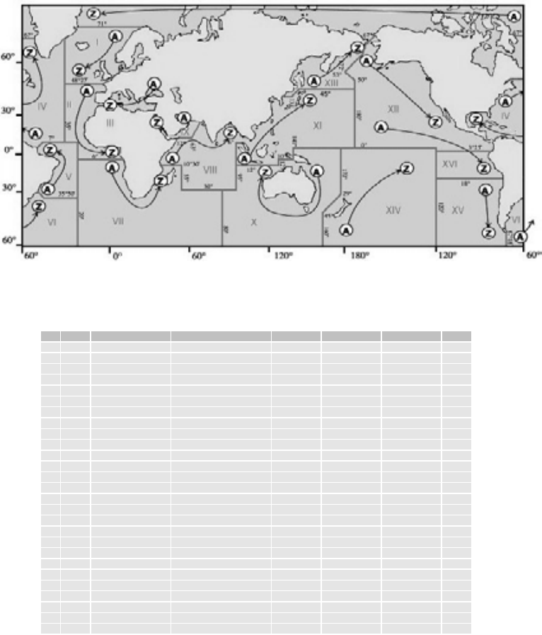
APPENDIX I: NAVTEX STATION DATABASE
518kHz NAVTEX Stations
Id Area Country Name Latitude Longitude Range (NM) Op
A15 Chile Antofagusta 23°40’S 70°25′W 300 Yes
A09 Iran Bushehr 28°58’N 50°50’E 300 Yes
A02 France Corsen 48°28’N 5°3’W 300 Yes
A11 Indonesia Jayapura 2°31’S 140°43’E 300 Yes
A04 USA Miami 25°30’N 80°23’W 240 Yes
A03 Russia Novorossiysk 44°43’N 37°47’E 300 Yes
A01 Norway Svalbard 78°4’N 13°38’E 450 Yes
A13 Russia Vladivostok 43°7’N 131°53’E 280 No
B11 Indonesia Amboina 3°42’S 128°12’E 300 Yes
B09 Bahrain Bahrain 26°9’N 50°28’E 300 Yes
B04 Bermuda Bermuda Harbour 32°23’N 64°41′W 280 Yes
B01 Norway Bodo 67°16’N 14°23’E 450 Yes
B13 Russia Kholmsk 47°2’N 142°3’E 300 Yes
B03 Ukraine Mariupol 47°6’N 37°33’E 280 Yes
B15 Chile Valparaiso 32°48’S 71°29′W 300 Yes
B07 Namibia Walvis Bay 23°3’S 14°37’E 380 Yes
C07 South Africa Cape Town 33°41’S 18°43’E 500 Yes
C08 Mauritius Mauritius 20°10’S 57°28’E 400 Yes
C01 Russia Murmansk 68°58’N 33°5’E 140 Yes
C03 Ukraine Odessa 46°29’N 30°44’E 280 Yes
C13 Russia Petropavlosk 53°0’N 158°40’E 280 No
C12 USA San Francisco 37°55’N 122°42′W 350 Yes
C04 Canada Sept -Iles 50°11’N 66°7’W 300 Yes
C11 Singapore Singapore 1°20’N 103°42’E 400 Yes
C15 Chile Talcahuano 36°42’S 73°6’W 300 Yes
D02 Spain Coruna 43°22’N 8°27′W 400 Yes
D01 Sweden Grimeton 57°6’N 12°23’E 299 Yes

Id Area Country Name Latitude Longitude Range (NM) Op
D03 Turkey Istanbul 41°4’N 28°57’E 300 Yes
D13 Russia Magadan 59°40’N 151°1’E 000 No
D12 Canada Prince Rupert 54°18’N 130°25′W 300 Yes
D15 Chile Puerto Montt 41°29’S 72°57’W 300 Yes
D04 Canada Sept -Iles 50°11’N 66°7’W 300 Yes
D11 Indonesia Ujungpandang 5°6’S 119°26’E 300 Yes
E13 Russia Beringovskiy 64°10’N 179°02′W 000 No
E11 Indonesia Jakarta 6°7’S 106°52’E 300 Yes
E15 Chile Magallanes 52°56’S 70°54′W 300 Yes
E01 UK Niton 50°35’N 1°18’W 270 Yes
E03 Turkey Samsun 41°17’N 36°20’E 300 Yes
E12 USA Savannah 32°8’N 81°42′W 200 Yes
F03 Turkey Antalya 36°53’N 30°42’E 300 Yes
F01 Russia Arkhangelsk 64°33’N 40°32’E 300 Yes
F09 Iran Bandar Abbas 27°8’N 57°4’E 300 Yes
F04 USA Boston (Ice Rep) 41°43’N 70°31’W 200 Yes
F02 Acores Horta 38°32’N 28°38’W 640 Yes
F15 Chile Isla De Pascua 27°9’S 109°25′W 300 Yes
F11 Thailand Krung Thep 13°44’N 100°34’E 200 Yes
F06 Uruguay La Paloma 34°40’S 54°9’W 280 Yes
F13 Russia Providenia Bukhta 64°10’N 173°10’W 000 No
G01 UK Cullercoats 55°4’N 1°28’W 270 Yes
G09 Saudi Arabia Damman 26°26’N 50°6’E 390 Yes
G15 Chile Isla De Pascua 27°9’S 109°25′W 300 Yes
G08 India Mumbai 19°5’N 72°50’E 299 Yes
G11 Japan Naha 26°9’N 127°46’E 400 Yes
G04 USA New Orleans 29°53’N 89°55’W 200 Yes
G02 Spain Tarifa 36°1’N 5°34’W 400 Yes
H15 Chile Antofagusta 23°40’S 70°25′W 300 Yes
H01 Sweden Bjuroklubb 64°28’N 21°36’E 300 Yes
H06 Dutch Antilles Curacao 12°10’N 68°52’W 250 Yes
H03 Greece Iraklion 35°20’N 25°7’E 280 Yes
H09 Saudi Arabia Jeddah 21°23’N 39°11’E 390 Yes
H11 Japan Moji 33°52’N 130°36’E 400 Yes
H04 Canada Prescott 44°20’N 81°10′W 300 Yes
H12 Canada Tofino 48°56’N 125°32′W 300 Yes
I03 Turkey Izmir 38°21’N 26°35’E 300 Yes
I02 Islas Canarias Las Palmas 28°9’N 15°25’W 400 Yes
I07 South Africa Port Elizabeth 33°57’S 25°31’E 500 Yes
I15 Chile Valparaiso 32°48’S 71°29′W 300 Yes
I11 Japan Yokohama 35°22’N 139°36’E 400 Yes
J01 Sweden Gislovshammer 55°29’N 14°19’E 300 Yes
J12 Alaska Kodiak 57°46’N 152°34′W 200 Yes
J11 Japan Otaru 43°12’N 141°0’E 400 Yes
J04 Canada Sydney 46°11’N 59°54′W 300 Yes
J15 Chile Talcahuano 36°42’S 73°6’W 300 Yes
J03 Bulgaria Varna 43°4’N 27°46’E 350 Yes
K03 Greece Kerkyra 39°45’N 19°52’E 280 Yes
K11 Japan Kushiro 42°59’N 144°23’E 400 Yes
K01 UK Niton (N.France) 50°35’N 1°18’W 270 Yes
L11 Hong Kong Hong Kong 22°13’N 114°15’E 299 Yes
L03 Greece Limnos 39°52’N 25°4’E 280 Yes
L15 Chile Magallanes 52°56’S 70°54′W 300 Yes
L01 Norway Rogaland 58°39’N 5°36’E 450 Yes
M02 Morocco Casablanca 33°36’N 7°38’W 180 No
M03 Cyprus Cyprus 35°10’N 33°26’E 200 Yes
M09 Oman Muscat 23°37’N 58°31’E 270 Yes
M01 Belgium Oostende (Thames) 51°11’N 2°48’E 150 Yes
M11 China Sanya 18°14’N 109°30’E 250 Yes
M06 Argentina Ushuaia Prefectur 54°48’S 68°18’W 280 Yes
N03 Egypt El Iskandariya 31°12’N 29°52’E 350 Yes
N11 China Guangzhou 23°9’N 113°29’E 250 Yes
N01 Norway Orlandet 63°40’N 9°33’E 450 Yes

Id Area Country Name Latitude Longitude Range (NM) Op
N04 USA Portsmouth 36°44’N 76°1′W 280 Yes
N06 Argentina Rio Gallegos 51°37’S 69°3’W 280 Yes
O06 Argentina Comodoro Rivadavi 45°51’S 67°25’W 280 Yes
O07 South Africa Durban 29°48’S 30°49’E 500 Yes
O11 China Fuzhou 26°2’N 119°18’E 250 Yes
O12 Hawaiian Islands Honolulu 21°22’N 158°9′W 350 Yes
O03 Malta Malta 35°49’N 14°32’E 400 Yes
O01 UK Portpatrick 54°51’N 5°7′W 270 Yes
O04 Canada St Johns 47°37’N 52°40’W 300 Yes
P06 Argentina Bahia Blanca 38°43’S 62°6′W 280 Yes
P11 Vietnam Hai Phong 20°43’N 106°44’E 400 No
P03 Israel Hefa 32°49’N 35°0’E 200 Yes
P01 Netherlands Ijmuiden 52°27’N 4°35’E 110 Yes
P09 Pakistan Karachi 24°51’N 67°3’E 400 Yes
P11 Taiwan Keelung 25°8’N 121°45’E 540 Yes
P11 Taiwan Lintou 23°33’N 119°38’E 350 Yes
P11 Taiwan Linyuan 22°29’N 120°25’E 540 Yes
P08 India Madras 13°8’N 80°17’E 299 Yes
P11 Taiwan Meilung 23°59’N 121°37’E 350 Yes
P04 Canada Thunder Bay 48°26’N 89°13’W 300 Yes
Q12 USA Long Beach 35°31’N 121°3′W 350 Yes
Q01 Ireland Malin Head 55°22’N 7°21’W 400 Yes
Q06 Argentina Mar Del Plata 38°3’S 57°32’W 280 Yes
Q11 China Shanghai 31°7’N 121°33’E 250 Yes
Q03 Croatia Split 43°30’N 16°29’E 085 Yes
Q04 Canada Sydney 46°11’N 59°54′W 300 Yes
R06 Argentina Buenos Aires 34°27’S 58°37’W 560 Yes
R11 China Dalian 38°52’N 121°31’E 250 Yes
R02 Portugal Monsanto 38°44’N 9°11’W 530 Yes
R01 Iceland Reykjavik 64°5’N 21°51’W 550 Yes
R04 Greenland Reykjavik 64°5’N 21°51′W 550 Yes
R03 Italy Roma 41°48’N 12°31’E 320 Yes
R12 Puerto Rico San Juan 18°28’N 67°4’W 200 Yes
S04 Canada Iqaluit 63°44’N 68°33′W 200 No
S11 Malaysia Labuan 5°54’N 118°0’E 350 Yes
S16 Peru Paita 5°5’S 81°7′W 200 Yes
T03 Italy Cagliari 39°14’N 9°14’E 320 Yes
T04 Canada Iqaluit 63°44’N 68°33′W 200 No
T11 Malaysia Kuching 4°27’N 114°1’E 350 Yes
T01 Belgium Oostende 51°11’N 2°48’E 050 Yes
U16 Peru Calleo 12°3’S 77°9’W 200 Yes
U04 Canada Fundy 43°45’N 66°10′W 300 Yes
U11 Malaysia Port Kelang 5°25’N 100°24’E 350 Yes
U01 Estonia Tallinn 59°30’N 24°30’E 300 Yes
U03 Italy Trieste 45°41’N 13°46’E 320 Yes
V03 Italy Augusta 37°14’N 15°14’E 320 Yes
V11 South Korea Chukpyon 37°3’N 129°26’E 200 Yes
V04 Canada Fundy 43°45’N 66°10′W 300 Yes
V11 Mariana Islands Guam 13°34’N 144°50’E 100 Yes
V01 Norway Vardo 70°22’N 31°6’E 450 Yes
W12 USA Astoria 46°10’N 123°49′W 216 Yes
W11 Vietnam Da Nang 16°5’N 108°13’E 400 Yes
W04 Greenland Kook Islands 64°4’N 52°1’W 400 No
W03 France La Garde 43°6’N 5°59’E 250 Yes
W16 Peru Mollendo 17°1’S 72°1’W 200 Yes
W11 South Korea Pyonsan 35°36’N 126°29’E 200 Yes
W01 Ireland Valentia (Dublin) 51°27’N 9°49’W 400 Yes
X11 Vietnam Ho Chi Minh-City 10°47’N 106°40’E 400 Yes
X12 Alaska Kodiak 57°47’N 152°32′W 200 Yes
X04 Canada Labrador 53°18’N 60°33′W 300 Yes
X09 Egypt Serapeum 30°28’N 32°22’E 200 Yes
X03 Spain Valencia 38°43’N 0°9’E 300 Yes
Notes:
No liability can be accepted for any inaccuracies or omissions in this
NAVTEX stations table, although every care has been taken to make it as
complete and accurate as possible.
Check our website www.mcmurdo.co.uk for information on updates to the
station database.
For updated NAVTEX station listings information refer to the current UK
‘Admiralty List of Radio Signals, Volume 5’ or equivalent national
publications.
All 518 kHz NAVTEX transmissions are in English language.
Local language NAVTEX services are available in some parts of the World
on 490 kHz and 4209.5 kHz.
APPENDIX II: MESSAGE TYPE INDICATORS
NAVTEX broadcasts use following message type letter:
A Navigational warnings
B Meteorological warnings
C Ice reports
D Search and rescue information, and pirate warnings
E Meteorological forecasts
F Pilot service messages
G DECCA messages
H LORAN messages
I OMEGA messages (Note: OMEGA has been discontinued)
J SATNAV messages (i.e. GPS or GLONASS)
L Navigational warnings — additional to letter A
V Notice to Fishermen (U.S. only)
W Environmental (U.S. only)
X Special services — allocation by IMO NAVTEX Panel
Y Special services — allocation by IMO NAVTEX Panel
Z No message on hand

APPENDIX III: DECLARATION OF CONFORMITY


28-227 Iss1
ICS NAV5plus
GMDSS NAVTEX Receiver
User Guide
VESSEL IDENTIFICATION INFORMATION
Name
Call Sign
MMSI
ICS NAV5plus S/N
RX frequencies 518 kHz
490 kHz
The technical data, information and illustrations contained in this publication were to
the best of our knowledge correct at the time of going to print. We reserve the right
to change specifications, equipment, installation and maintenance instructions
without notice as part of our policy of continuous product development and
improvement. No part of this publication may be reproduced, stored in a retrieval
system or transmitted in any form, electronic or otherwise without permission in
writing from McMurdo Limited. No liability can be accepted for any inaccuracies or
omissions in the publication, although every care has been taken to make it as
complete and accurate as possible.
Safety Warnings
This instrument is for use as an aid to sailors and should not lead to a
reduction in the level of good seamanship required at all times.
Reception of messages cannot always be guaranteed as this depends
on local radio propagation.
Contents
Quick Start ………………………………………………………………………………………. 1
Introduction ……………………………………………………………………………………… 1
How To Operate Your ICS NAV5plus………………………………………………….. 3
System Alarms…………………………………………………………………………………. 8
Serial Output……………………………………………………………………………………. 9
Tearing off a Printout ………………………………………………………………………. 11
Paper Loading………………………………………………………………………………… 11
Installation……………………………………………………………………………………… 14
Self Test………………………………………………………………………………………… 24
Troubleshooting Guide ……………………………………………………………………. 26
Warranty ……………………………………………………………………………………….. 29
Options………………………………………………………………………………………….. 30
Specifications…………………………………………………………………………………. 31
Appendix II: Message Type Indicators ………………………………………………. 36
Appendix III: Declaration of Conformity ……………………………………………… 37
Please take the time to read this manual carefully. It contains some
essential information regarding the operation and maintenance of the
product and a useful background to the NAVTEX system.
We recommend that you regularly visit the McMurdo website
www.mcmurdo.co.uk for information on updates, the availability of software
enhancements, further options and support. The support pages contain
frequently asked questions about the ICS NAV5plus that you may find
useful. There is also a NAVTEX database providing a list of operational
NAVTEX stations and their details.
The IMO and various national coastguards also operate informative
websites that you may wish to visit, see the links page at
www.mcmurdo.co.uk.
1
QUICK START
You will find this product extremely easy to operate.
• Follow the installation guidelines
• Re-check the cable connections
• Apply power
• Switch on the ICS NAV5plus
• The ICS NAV5plus will now print NAVTEX messages
INTRODUCTION
NAVTEX is a method of transmitting navigational warnings and weather
forecasts from designated coast radio stations. All English language
transmissions are made on 518 kHz. Each station is allocated several time
‘slots’ during the day, when it is permitted to transmit; these are normally at
four hourly intervals. The only exceptions to this are gale warnings and
search and rescue messages, which may be transmitted at any time.
Reception of NAVTEX is normally limited to an area of 200 — 300 miles
radius around each transmitting station, although considerably greater
ranges are possible at night.
Subject to IMO approval, additional local language transmissions may be
made on 490 kHz.
The ICS NAV5plus has been designed to the latest European and
International specifications to provide up to date weather and navigation
warning information to commercial vessels. It meets IMO requirements
under GMDSS and is designed for simplicity of operation. It will provide
reliable printed information day after day within designated NAVTEX
coverage areas.
2
Installation is straightforward. Connect the ICS NAV5plus to a 12 or 24 volt
DC supply and connect a suitable antenna. Switch it on, and it will start
printing NAVTEX messages without further manual intervention. Note that if
there are only a couple of NAVTEX stations within range it may be several
hours before you receive the first message
If all stations and message types are left selected, the ICS NAV5plus may
overwhelm you with information. It can therefore be set up to print only
those stations and message categories you want to receive and which are
applicable to the area in which you are sailing.
Normally, routine messages are repeated at four hourly intervals. Provided
that the ICS NAV5plus is left running, repeated messages are not printed
again. The suppression of repeated messages stops three days (72 hours)
after the last transmission of the message.
Permanent installation of the ICS NAV5plus can be made with the
bulkhead-mounting bracket provided. Alternatively, the optional FMT-2
flush panel mounting kit, part number 913-24, may be purchased.
A NAVTEX antenna should be mounted where it is elevated clear of metal
objects in a location where it cannot easily be damaged.
Please read the installation section of the user guide thoroughly
before attempting installation of the ICS NAV5plus.
3
HOW TO OPERATE YOUR ICS NAV5PLUS
Initial Operation
Switch on the ICS NAV5plus by pressing the power button
The LCD display backlight will come on.
The LCD data display will show :
The “V2.07” is the software version, which may vary.
A short self-test is performed, then the ICS NAV5plus is ready to receive
NAVTEX messages.
The factory default setting is for all NAVTEX stations and message
categories to be printed.
To change the settings, refer to the SETUP section.
ICS NAV-5 V2.07
LOG EMPTY
4
SETUP
Setup Controls
The diagram shows the main functions of the front panel controls:
NAVTEX Message Type Selection
At the beginning of each NAVTEX message there is a message header
which identifies the source and nature of message using an identity code.
For example GA59 :-
Station Message category Serial No.
G A 59
This identifies which station has transmitted the message and the nature of
the message.
It is possible to select the NAVTEX stations you wish to receive messages
from and to restrict certain message categories.
DIM (backlighting)
PAPER FEED
Start programming Select or de-select Finish programming
stations / messages
POWER ON / OFF
STOP ALARM
5
DUAL CHANNEL OPERATION
The ICS NAV5plus is a dual channel receiver.
The and keys on the keypad are used to switch the LCD display
between RX-A (the standard 518 kHz receiver) and RX-B (the 490 kHz
second receiver ).
The LAST MSG display shows the identity number of the last message
received on that receiver and the two-dot signal indicator will flash if there is
a signal being received from that receiver.
• Pressing and will display the corresponding information for the
other receiver.
Notes:
Although the and keys are used to select which receiver is shown
on the display, it is important to realise that both receivers are actively
receiving signals all the time.
If messages are being transmitted at the same time on both channels, both
messages will be received and printed.
Messages from RX-B are identified separately on the printout.
Only messages from the 518 kHz receiver channel will be present on the
RS422 serial output.
6
NAVTEX Stations Setup Procedure
When the key is pressed, the set up mode for the selected receiver will
be started. This enables the stations and message types required for that
receiver to be set. The two receivers are set up independently.
Station selection is displayed first:
Press followed by either the or the buttons, one push of either
button will select, a second push will deselect.
Deselected stations are indicated by a ‘dash’ (–).
Each NAVTEX transmitting station has its own identifying letter. A list of
these can be found in the NAVTEX Station Designations table section of
this manual (Appendix 1).
If you do not know which stations cover your area, start by leaving them all
stations selected. You will soon find which stations are relevant to you.
Press to store the NAVTEX station and message category selections.
STN: ABCDEFGHIJ
KLMNOP
RSTUVWX
7
NAVTEX Message Category Setup Procedure
• Once you have completed the NAVTEX station selection, press to
change to the message category selection screen:
Message categories are identified by a single letter.
Press followed by either the or the buttons; one push of either
button will select, a second push will deselect.
Deselected message categories are indicated by a ‘dash’ (–).
• Message categories, A, B, D and L cannot be deselected.
Press to store the NAVTEX station and message category selections.
For a table of NAVTEX message categories, see APPENDIX II.
MSG: ABCDEFGHIJ
KLMNOP
RSTUVWXYZ
8
SYSTEM ALARMS
Audible Alarms
The alarm signal within the ICS NAV5plus will sound under the following
circumstances:—
• INCORRECT KEY PRESSED
• PAPER OUT
• LOW BATTERY ( Power supply voltage is less than 9V DC)
• VITAL NAVTEX MESSAGE
Remove the cause of the alarm and then press the key to stop the
alarm.
Visible Alarms
The visible alarms will show on the LCD under the following
circumstances:—
• PAPER OUT
• LOW BATTERY ( Power supply voltage is less than 9V DC)
• VITAL NAVTEX MESSAGE
Remove the cause of the alarm and then press the key to stop the
alarm.
9
SERIAL OUTPUT
The ICS NAV5plus has an EIA RS422A-compatible serial output which can
be used to connect the ICS NAV5plus to other equipment such as an
integrated bridge system or a PC running charting software.
The serial output operates all the time that the ICS NAV5plus is switched on
– there is no ON/OFF control for the serial output.
All correctly received NAVTEX messages from the 518 kHz receiver are
sent to the serial output. The station and message category settings for
printing within the ICS NAV5plus are ignored.
It is anticipated that the external equipment (e.g. a PC running charting
software) will have its own method of selecting stations and message
categories and as such ALL NAVTEX messages received by the ICS
NAV5plus will be output.
Note: Only messages from the 518 kHz receiver channel will be present on
the RS422 serial output.
Connecting to the Serial Output
Main Connector
Pin Function
3 EIA-RS-422-A Output (TxA)
4 EIA-RS-422-A Output (TxB)
The RS422 output is ‘simplex’ which means that multiple receivers can be
connected to the ICS NAV5plus but the ICS NAV5plus is the only
transmitter.
The RS422 standard for connecting equipments specify that, for a short
cable with only one receiver, the cable may be unterminated. For longer
cables (20 metres or more) or installations with multiple receivers, a
termination resistor should be fitted at the far end of the cable run from the
ICS NAV5plus. The resistor value should be the ‘characteristic impedance’
of the cable, which typically is 100 to 120ohms. A ¼ W resistor is sufficient.
The cable used should be twisted pair 7/0.2 mm or similar.
10
Configuring the RS422 Receiver
The receiving device (a PC running charting software, or similar) needs to
be configured so that it can receive the NAVTEX messages output from the
ICS NAV5plus. Set up the RS422 receiver’s communication port as:
Baud rate 4800
8 data bits
1 stop bit
no parity
XON/XOFF
Connecting to an RS422 Device
If the receiver is an RS422 device then only 2 connections are required:
Pin ICS NAV5plus
Connection RS422 Receiver Connection
3 Output (Y) Input (A)
4 Output (Z) Input (B)
Note that, because receiver terminology varies between manufacturers, it
may be necessary to swap the two connections for the receiver to function
correctly. Don’t worry – you won’t damage the interface.
Connecting to a RS232 Device
If the receiver is a RS232 device, eg a computer serial (COM) port, then a
RS422 to RS232 converter is required.
A suitable converter is Amplicon ‘Model 485F9/485H9’, although any similar
product should be compatible. Be sure to follow the connection instructions
supplied with your converter.
11
TEARING OFF A PRINTOUT
Use a gentle up or downward and sideways motion to tear the paper at the
exit point of the ICS NAV5plus case.
Warning: DO NOT PULL THE PAPER THROUGH THE PRINTER AS
THIS ACTION MAY DAMAGE THE PRINTER MECHANISM
Always use the paper feed button to feed the paper clear of the
mechanism.
PAPER LOADING
The ICS NAV5plus is supplied with one roll of paper fitted. At the end of this
paper roll the ICS NAV5plus will sound an alarm and printing will stop.
Early warning that the paper is about to run out is given by red stripes on
the paper.
Should the paper run out in the middle of a message, information will not be
lost provided that the ICS NAV5plus is not switched off whilst the paper roll
is replaced.
Ensure that proper anti-static procedures are applied when installing or
servicing the ICS NAV5plus and also when replacing the paper roll. Take
care to discharge any static that you may be carrying by touching exposed
metalwork on the case prior to replacing the paper roll.
• To remove the remaining paper, open the paper loading door. Push a
top corner of the door to release the locking door catch
• Tear off the paper where it enters the printer mechanism
• Remove the old paper roll
• Remove the plastic spindle from inside the paper roll
• Press the paper feed button to feed the remaining paper through
the printer mechanism
Warning: DO NOT PULL THE PAPER THROUGH THE PRINTER AS
THIS ACTION MAY DAMAGE THE PRINTER MECHANISM
12
• Place the new roll onto the spindle with the paper emerging from the
top of the roll pointing towards you
• Mount the new roll and spindle onto the roll bracket
• Insert the paper into the slot at the base of the printer mechanism, and
feed it in as far as it will go
It is important that the edge of the new paper roll is cut straight and
that the paper is dry. Use scissors to prepare a clean straight paper
edge.
• Check that the paper is inserted so that the heat sensitive surface is
uppermost as the paper exits the printer
• Check that the paper roll is correctly aligned with the print mechanism
as shown below
CORRECT INCORRECT
13
Press the paper feed button until the paper appears through the door
exit
New supplies of paper rolls can be ordered from McMurdo dealers, or
contact McMurdo Tel +44 (0) 23 9262 3900 Fax +44 (0) 23 9262 3999,
Email sales@mcmurdo.co.uk.
Quote order code: NAVTEX Rolls.
This specifies a box of eight rolls of paper.
The paper roll size is 80mm x 20m with a maximum diameter of 42mm and
an internal spindle (hole) diameter of 12mm.
An updated list of McMurdo distributors is available on the McMurdo
website (www.mcmurdo.co.uk) Distributors page
14
INSTALLATION
ICS NAV5plus System Overview
NAVTEX
ANTENNA
15
Mechanical Mounting using U-Bracket Supplied
The standard bulkhead mounting U-Bracket can be used to mount the ICS
NAV5plus above or below a horizontal (or near horizontal) surface.
• Use the U-bracket as a template to mark out the 4 fixing holes on
the mounting surface.
• Drill 4 off fixing pilot holes (1/8 inch / 2.5 mm diameter for
hardwood, or 3/32 inch / 3mm diameter for softwood or plywood).
• Use the No.10 S/S pozidrive screws supplied to attach the U-
Bracket to the mounting surface.
• Use the two 25 mm diameter rubber washers supplied between the
U-Bracket and the ICS NAV5plus case.
• Make the necessary electrical connections to the rear of the ICS
NAV5plus.
• Ensure that the two handwheel knobs are inserted through the
bracket and rubber washers on each end of the ICS NAV5plus.
• Hand tighten the knobs.
16
Mechanical Mounting using the Optional Flush Mount Kit
If the ICS NAV5plus is to be mounted through a flat panel, it is advised that
you purchase the FMT-2 flush mounting kit option, part 913-24.
Full fitting instructions are included in the FMT-2 flush mounting kit.
Warning: Do not mount the ICS NAV5plus in a position where sea spray
can reach it, or where it may be exposed to direct sunlight
17
Electrical Connections
A connection must be made to a 12 or 24 V DC supply via a circuit breaker
capable of supplying at least 2 amps. Connection should be to the ships
radio battery and be in accordance with GMDSS requirements.
• Connections are made directly to the screw terminals on the ICS
NAV5plus mating connector at the rear of the unit using the 1m length
cable provided.
• Use cable ties to restrain the wiring, and so prevent it becoming
weakened by vibration. The connecting cables should be restrained by
securing them to the rear of the ICS NAV5plus bracket, or to adjacent
metalwork.
Safety Warning
The ICS NAV5plus has been designed and manufactured to be
completely safe when used in accordance with the instructions
given in this manual. To ensure that the complete installation is
safe, it is essential that a fuse or circuit breaker is installed in the
supply cable as described in the Installation Section of this
manual.
The ICS NAV5plus is supplied with a DC power cable and an in-
line Type ‘T’ 2.5 amp fuse. It is essential that this fuse is included
in the installation.
To ensure the best possible protection of the ICS NAV5plus from
static electricity or nearby lighting strikes, the pre-fitted green
grounding wire (connected to the safety earth stud) must be
connected to a nearby (hull) electrical grounding point.
18
Interface Connections
ICS NAV5plus rear panel connections:
Main Connector
Pin Function
1 Not used
2 Not used
3 EIA-RS-422-A Output (Y)
4 EIA-RS-422-A Output (Z)
5 Not used
6 Not used
7 Power input (negative)
8 Power input (positive)
9 N/O Alarm contact (2 A max @ 24 V DC)
10 N/O Alarm contact (2 A max @ 24 V DC)
Antenna Connector
Pin Function
1 Active antenna input*
2 Active antenna screen
3 Safety ground
4 Antenna ground
5 Passive antenna screen
6 Passive antenna input
* WARNING: DC voltage is present on Pin 1
NOTES:
For each connector, Pin 1 is on the right, looking at the rear of the ICS
NAV5plus.
• The auxiliary alarm contact is capable of switching up to 24 V DC at up
to 2 A. The contacts are not connected to any internal voltages
• The power supply input is isolated from the case and antenna. It must
remain within the range 10.8 – 32 V DC at all times.
19
Selecting a Suitable Antenna
The ICS NAV5plus receives transmissions on two frequencies. 518 kHz
transmissions are in International English; 490 kHz tranmissions may be in
a local language.
To receive on both frequencies the ICS NAV5plus must be used with a
broadband antenna that covers both 518 kHz and 490 kHz.
Only one antenna can be connected to the ICS NAV5plus, either to the
passive antenna input or to the active antenna input.
Several different antenna types are recommended for the ICS NAV5plus.
The best option will depend upon the receive frequencies required and the
ease of installation.
Choice of Antenna
Antenna 490 kHz 518 kHz
ANT/w 99
NAV-ANT/w * 99
NAV-ACTIVE * 99
Whip antenna with 50 ohm match 99
Long wire with 50 ohm match 99
* recommended options
The ICS NAV5plus must be used with a low impedance 50 Ω antenna
or an antenna with a 50 Ω matching network.
A ‘mis-matched’ or ‘high impedance’ whip or wire antenna should not be
used or the operational range of NAVTEX reception will be greatly reduced.
• If a ‘Wire’ or ‘long whip’ antenna is used with the ICS NAV5plus it must
be fitted with a 50 Ω matching transformer.
20
Important
NAVTEX antennas must be mounted clear of obstructions and at least
0.5 metres away from other antennas.
Ensure that they cannot be snagged by mooring warps or running
rigging or engulfed by green water.
Antennas should always be mounted vertically.
Installation of a NAVTEX Antenna
The NAVTEX antenna should be mounted vertically, in an elevated
position. Metal, rigging or other antennas must not be located in the ‘NO
GO cone’ surrounding the upper part.
Keep this area clear
21
Installation procedure: NAV-ANT/w & NAV-ACTIVE, NAV-
CABLE, NAV-CLAMP/a
Start the antenna cable installation from the ICS NAV5plus (lower) end first.
Where the cable passes through bulkheads or decks, waterproof deck
glands should be installed. Securely fasten the cable against vibration using
plastic cable tie wraps.
Typical installation of
NAV-ANT/w, NAV-CLAMP/a and
NAV-CABLE
Typical installation of
NAV-ACTIVE or NAV-ANT/w,
NAV-CLAMP/a and NAV-CABLE
22
Antenna connection
Pass the cable though the black plastic boot and prepare the end of the
cable as shown in the diagram, folding the cable braid back and screwing
the PL259 connector firmly in place. To ensure a good connection it is
recommended that the centre pin is soldered.
Screw firmly in place
Solder centre pin connection
Side pin (2)
Centre pin (1)
NAV-CABLE assembly detail
ICS NAV5plus connection
If required, the NAV-CABLE may be extended with 50 ohm coaxial cable
and connectors. The maximum cable length should not exceed 100m.
Ensure that any cable joints are well secured and waterproofed using self-
amalgamating (rubber) tape.
23
Active Antenna Installation
McMurdo recommend the NAV-ACTIVE 905.05, an active NAVTEX
antenna with PL socket and 1 inch nut fixing.
The ICS NAV5plus provides a regulated 9 V DC 100 mA output to provide
power for an active antenna. Check that your active antenna is compatible
with this power output. If it is not, then an external power supply interface
will be required. Your antenna supplier should be able to provide this.
If you use an external power supply interface then you must connect the RF
output from the interface to the ICS NAV5plus passive antenna input rather
than the active antenna input.
Securely mount the active antenna to a vertical surface or pole, route the
connecting cable though to the ICS NAV5plus using cable glands to pass
though bulkheads as required.
Connect the active antenna output coaxial cable centre core to Antenna
Connector Terminal 1 and the coaxial screen to Terminal 2.
Passive Antenna Installation
Connect the passive antenna output coaxial cable centre core to Antenna
Connector Terminal 6 and the coaxial screen to Terminal 5
Dual Antenna Installation
A dual antenna installation is NOT possible.
NAVTEX AC Power Supply Unit
Consult the installation instructions packed with the power supply.
An additional ground wire may be connected between the green safety
earth wire on the ICS NAV5plus and the ground terminal on the NAVTEX
Power Supply Unit.
24
SELF TEST
If you have any doubts as to whether the ICS NAV5plus is working correctly
run the self-test.
‘Self Test’ is selected by holding down the feed button while the ICS
NAV5plus is switched on using the power button.
The ICS NAV5plus will print out the test results and then start normal
operation.
If all tests are passed, a printout will appear as shown:
pqrstuvwxyz{“}~
HIJKLMNOPQRSTUVWXYZ[]^_’abcdefghijklmno
!”#$%&’()*+,-./0123456789:;<=>/?@ABCDEFG
ROMDATE : Nov 21 2002
ROM : ICS NAV5plus V2.07
DISPLAY : PASS
RAM : PASS
CPU : PASS
RXA-I : PASS
RXA-Q : PASS
RXB-I : PASS
RXB-Q : PASS
PAPER SENSOR : PASS
HEAD RESISTANCE : C
*
* Either A, B or C will show here.
25
Notes :
The first three lines of this print out are simply a test of the printer.
The ROMDATE and ROM lines change in line with product development.
The DISPLAY line tests the LCD display module.
The RAM and CPU lines test the memory and central processor.
The RXA-I and RXA-Q lines test the two signal paths in the 518 kHz radio
receiver.
The RXB-I and RXB-Q lines test the two signal paths in the 490 kHz radio
receiver.
The PAPER SENSOR tests whether the unit can recognise the presence of
paper in the roll holder.
The HEAD RESISTANCE letter is for service use only, and should match
the head resistance mark on the printer assembly.
This self-test is carried out automatically each time the unit is switched on,
but the results are not reported unless a fault is detected.
Three beeps mark the progress of this test.
As an additional receiver confidence test, the ICS NAV5plus also flashes
two small squares at the right hand side of the display whenever it is
receiving a NAVTEX signal, even if the message is not selected for printing.
26
TROUBLESHOOTING GUIDE
Check that :-
• The antenna is mounted vertically, and is sited clear of obstructions
• The vessel is operating within the coverage area of a NAVTEX
transmitter
• The NAVTEX station(s) selected are transmitting, two small squares at
the right hand side of the ICS NAV5plus display show whenever a
NAVTEX signal is received
• The required NAVTEX station and message categories have not been
de-selected in the ICS NAV5plus set-up menu
Antenna
Check that the antenna is clear of obstructions and has not suffered
external damage. Check that the antenna cable is not damaged.
Receiver
Perform a system self test — refer to Self Test section for details.
• At scheduled transmission time, look for two small squares at the right
hand side of the ICS NAV5plus display; these flash whenever a
NAVTEX signal is received.
Printer
If there is no sign of life from the printer after power up and a printer fault is
shown on the LCD display, check that there is no paper jammed in the
printer.
• If the printer operates but nothing is printed, check that the paper roll is
of a type recommended by ICS and that the ‘heat sensitive side’ of the
paper is uppermost (as that paper exits the door, test with a ‘hot’ item).
Paper Out
• In the case of a “Paper Out” alarm, replace the paper roll
• If the paper has not run out, check that the paper roll is fitted correctly
27
Default Reset
Use the Default Reset to reset the ICS NAV5plus to the factory default
settings. This sets all NAVTEX stations and message categories to on.
• Turn the unit off
• Hold down the alarm silence button while pushing the
power button
• The ICS NAV5plus will sound a bleep, and load default settings
Self Test
Run the ICS NAV5plus self test, refer to ‘self test’ section for details.
Should any item on the self test fail, turn the ICS NAV5plus off and on again
and repeat the system self test. Should any item on the self test list fail a
second time, contact your supplier for advice or call the McMurdo Technical
Help Line for assistance.
Tel +44 (0) 23 9262 3900
Fax +44 (0) 23 9262 3999
Email: customerservice@mcmurdo.co.uk
28
Printer Jam
Mishandling of the paper when installing a new paper roll can sometimes
cause the printer to jam.
If the moving printer head is allowed to catch the edge of the paper roll the
printer mechanism may stall. This will result in a ‘printer fault’ being
reported by the unit (alarm : ‘bleep-bleep’, ‘bleep-bleep’, ‘bleep-bleep’).
This condition may be avoided by first ensuring that the new paper roll has
a flat, cleanly cut edge.
• Consult the ‘Paper Loading’ instructions for details of the paper load
procedure
Should a paper jam occur, do not pull on the paper or try to force the printer
head sideways as such action may cause damage to the printer and may
invalidate your warranty.
Clearing a Paper Jam
As the procedure to clear a ‘stalled printer’ involves disassembly of the
main unit it is recommended that this should only be attempted by
authorised service personnel.
In the first instance :
Contact the dealer who supplied your unit for further instructions.
If you are still not satisfied contact the McMurdo Electronics Technical
Helpline for assistance.
Tel +44 (0) 23 9262 3900
Fax +44 (0) 23 9262 3999
Email: customerservice@mcmurdo.co.uk
Software Upgrade
From time to time software upgrades may be available. Check our website
for information on new releases.
29
WARRANTY
Subject to the provisions set out below McMurdo Limited warrants that this product will be free
of defects in materials and workmanship for a period of 24 months from the date of sale.
McMurdo Limited will not be liable to the buyer under the above warranty:-
• for any defect arising from fair wear and tear, wilful damage, negligence, abnormal
working conditions, failure to follow McMurdo Limited’s instructions (whether oral or in
writing) including a failure to install properly and/or to use batteries recommended and/or
supplied by McMurdo Limited, misuse or alterations or repair of the product by persons
other than McMurdo Limited or an Approved Service Agent;
• for parts, materials or equipment not manufactured by McMurdo Limited in respect of
which the buyer shall only be entitled to the benefit of any warranty or guarantee given by
the manufacturer to McMurdo Limited;
• for the battery storage life which is specifically excluded from this warranty;
• if the total price for the product has not been paid.
McMurdo Limited does not make any other promises or warranties (express, implied or
statutory) about the product except where the product is sold to a consumer in which case the
statutory rights of a consumer are not to be affected.
In order to be valid, claims must be made under the above warranty in writing as soon as
practicable after discovery of the defect or failure and within the warranty period referred to
above. Proof of purchase will be required. The claim should be sent together with the product
in question to the address set out below or to an Approved Service Agent.
Following a valid warranty claim McMurdo Limited shall be entitled to repair or replace the
product (or part) in question free of charge, or at McMurdo Limited’s sole discretion to refund to
the buyer the price of the product (or a proportional part of the price). McMurdo Limited shall
not be liable to a buyer who is not a consumer for any other loss or damage (whether indirect,
special or consequential loss of profit or otherwise) costs, expenses or other claims for
compensation which arise out of or in connection with this product. In the case of a consumer
McMurdo Limited shall only be liable where other loss or damage is foreseeable.
Nothing shall limit McMurdo Limited’s liability for death or personal injury caused by its
negligence.
This warranty is to be interpreted under English law.
All enquiries relating to this warranty or Approved Service Agents should be sent to:
McMurdo Limited
Silver Point, Airport Service Road, Hampshire, PO3 5PB, United Kingdom
Telephone: Int + 44 (0) 23 9262 3900 Fax: Int + 44 (0) 23 9262 3999
Web: www.mcmurdo.co.uk Email:sales@mcmurdo.co.uk
30
OPTIONS
The following ICS NAV5plus ancillary parts can be purchased:
Model Description Code
ICS NAV5plus Dual channel SOLAS printing NAVTEX Receiver 915-05
ICS NAV5plus Cyrillic Dual channel SOLAS printing NAVTEX Receiver
with Cyrillic alphabet support 916-06
Passive NAVTEX
antenna 518 — 490kHz, PL socket, white glass fibre
construction with 1inch nut fitting 905-03
Active NAVTEX
antenna 518 — 490kHz + 4209.5 kHz, PL Socket, white
glass fibre construction with 1inch nut fitting 905-05
NAV-CLAMP Pole mount stand-off bracket for NAVTEX
Antenna, 1inch bolt mount fitting. 903-01
NAV-CLAMP /b Pole or Wall mount stand-off bracket for NAVTEX
Antenna, 1inch bolt mount fitting 903-02
NAV-CLAMP /c Deck mount for NAVTEX antenna, 1inch bolt
mount fitting 903-04
NAV-CABLE 20 20m antenna cable kit 903-00
FMT2 Flush Mount
Kit Panel mounting kit for ICS NAV5plus 913-24
NAV-ROLLS Box of 8 paper rolls 913-13
NAV5plus Technical
Manual Service and maintenance information 28-230
CIS-CERT Russian Register of Shipping Certificate TBA
CHI-CERT Chinese Register of Shipping Certificate TBA
SPECIFICATIONS
Receiver
RxA Receiver Frequency 518 kHz
RxB Receiver Frequency 490 kHz
Sensitivity <2 microvolts
Frequency stability +/- 10 Hz
Antenna Input 50 ohms
NAVTEX Reception conforms to ITU-R 540-2, ETS 300-065
Environmental
Meets the relevant parts of BS EN 60945
Printer Specification
Type Thermal, 40 chars per line
Character Matrix 7 x 5
Paper Roll 80mm wide x 20m long
Paper Out Audible and visual alarm
Front Panel 2 line x 16 character backlit LCD
Membrane keypad
Controls
Power ON/OFF
LCD backlight dim
Paper feed
Stop alarm
Four programming keys
Serial Interface
EIA-RS-422-A compatible o/p
8 data bits
1 stop bit
No parity
Baud rate 4800
518 kHz receiver channel messages
only
Rear Connections
10 way power and RS422
6way antenna
Earth stud
Alarms
Vital message receipt
Paper Out
Operating Temperature Range -15 to +55 °C
Storage Temperature Range -20 to +55 °C
Humidity 0 to 95%, non-condensing
Mounting Below decks, desk-top,
bulkhead or panel mount
Weight 1500 g (approx.)
Dimensions 252W x 106H x 120D mm
Mounting Shelf/bulkhead
FMT-2 panel mount option
Power
Voltage range 10.8 V to 32 V
Consumption (Typical) Standby 1.5 W
Printing 2.5 W
Fused externally 2.5A Type ‘T’
Note: Specifications may be changed without notice.
APPENDIX I: NAVTEX STATION DATABASE
518kHz NAVTEX Stations
Id Area Country Name Latitude Longitude Range (NM) Op
A15 Chile Antofagusta 23°40’S 70°25′W 300 Yes
A09 Iran Bushehr 28°58’N 50°50’E 300 Yes
A02 France Corsen 48°28’N 5°3’W 300 Yes
A11 Indonesia Jayapura 2°31’S 140°43’E 300 Yes
A04 USA Miami 25°30’N 80°23’W 240 Yes
A03 Russia Novorossiysk 44°43’N 37°47’E 300 Yes
A01 Norway Svalbard 78°4’N 13°38’E 450 Yes
A13 Russia Vladivostok 43°7’N 131°53’E 280 No
B11 Indonesia Amboina 3°42’S 128°12’E 300 Yes
B09 Bahrain Bahrain 26°9’N 50°28’E 300 Yes
B04 Bermuda Bermuda Harbour 32°23’N 64°41′W 280 Yes
B01 Norway Bodo 67°16’N 14°23’E 450 Yes
B13 Russia Kholmsk 47°2’N 142°3’E 300 Yes
B03 Ukraine Mariupol 47°6’N 37°33’E 280 Yes
B15 Chile Valparaiso 32°48’S 71°29′W 300 Yes
B07 Namibia Walvis Bay 23°3’S 14°37’E 380 Yes
C07 South Africa Cape Town 33°41’S 18°43’E 500 Yes
C08 Mauritius Mauritius 20°10’S 57°28’E 400 Yes
C01 Russia Murmansk 68°58’N 33°5’E 140 Yes
C03 Ukraine Odessa 46°29’N 30°44’E 280 Yes
C13 Russia Petropavlosk 53°0’N 158°40’E 280 No
C12 USA San Francisco 37°55’N 122°42′W 350 Yes
C04 Canada Sept -Iles 50°11’N 66°7’W 300 Yes
C11 Singapore Singapore 1°20’N 103°42’E 400 Yes
C15 Chile Talcahuano 36°42’S 73°6’W 300 Yes
D02 Spain Coruna 43°22’N 8°27′W 400 Yes
D01 Sweden Grimeton 57°6’N 12°23’E 299 Yes
Id Area Country Name Latitude Longitude Range (NM) Op
D03 Turkey Istanbul 41°4’N 28°57’E 300 Yes
D13 Russia Magadan 59°40’N 151°1’E 000 No
D12 Canada Prince Rupert 54°18’N 130°25′W 300 Yes
D15 Chile Puerto Montt 41°29’S 72°57’W 300 Yes
D04 Canada Sept -Iles 50°11’N 66°7’W 300 Yes
D11 Indonesia Ujungpandang 5°6’S 119°26’E 300 Yes
E13 Russia Beringovskiy 64°10’N 179°02′W 000 No
E11 Indonesia Jakarta 6°7’S 106°52’E 300 Yes
E15 Chile Magallanes 52°56’S 70°54′W 300 Yes
E01 UK Niton 50°35’N 1°18’W 270 Yes
E03 Turkey Samsun 41°17’N 36°20’E 300 Yes
E12 USA Savannah 32°8’N 81°42′W 200 Yes
F03 Turkey Antalya 36°53’N 30°42’E 300 Yes
F01 Russia Arkhangelsk 64°33’N 40°32’E 300 Yes
F09 Iran Bandar Abbas 27°8’N 57°4’E 300 Yes
F04 USA Boston (Ice Rep) 41°43’N 70°31’W 200 Yes
F02 Acores Horta 38°32’N 28°38’W 640 Yes
F15 Chile Isla De Pascua 27°9’S 109°25′W 300 Yes
F11 Thailand Krung Thep 13°44’N 100°34’E 200 Yes
F06 Uruguay La Paloma 34°40’S 54°9’W 280 Yes
F13 Russia Providenia Bukhta 64°10’N 173°10’W 000 No
G01 UK Cullercoats 55°4’N 1°28’W 270 Yes
G09 Saudi Arabia Damman 26°26’N 50°6’E 390 Yes
G15 Chile Isla De Pascua 27°9’S 109°25′W 300 Yes
G08 India Mumbai 19°5’N 72°50’E 299 Yes
G11 Japan Naha 26°9’N 127°46’E 400 Yes
G04 USA New Orleans 29°53’N 89°55’W 200 Yes
G02 Spain Tarifa 36°1’N 5°34’W 400 Yes
H15 Chile Antofagusta 23°40’S 70°25′W 300 Yes
H01 Sweden Bjuroklubb 64°28’N 21°36’E 300 Yes
H06 Dutch Antilles Curacao 12°10’N 68°52’W 250 Yes
H03 Greece Iraklion 35°20’N 25°7’E 280 Yes
H09 Saudi Arabia Jeddah 21°23’N 39°11’E 390 Yes
H11 Japan Moji 33°52’N 130°36’E 400 Yes
H04 Canada Prescott 44°20’N 81°10′W 300 Yes
H12 Canada Tofino 48°56’N 125°32′W 300 Yes
I03 Turkey Izmir 38°21’N 26°35’E 300 Yes
I02 Islas Canarias Las Palmas 28°9’N 15°25’W 400 Yes
I07 South Africa Port Elizabeth 33°57’S 25°31’E 500 Yes
I15 Chile Valparaiso 32°48’S 71°29′W 300 Yes
I11 Japan Yokohama 35°22’N 139°36’E 400 Yes
J01 Sweden Gislovshammer 55°29’N 14°19’E 300 Yes
J12 Alaska Kodiak 57°46’N 152°34′W 200 Yes
J11 Japan Otaru 43°12’N 141°0’E 400 Yes
J04 Canada Sydney 46°11’N 59°54′W 300 Yes
J15 Chile Talcahuano 36°42’S 73°6’W 300 Yes
J03 Bulgaria Varna 43°4’N 27°46’E 350 Yes
K03 Greece Kerkyra 39°45’N 19°52’E 280 Yes
K11 Japan Kushiro 42°59’N 144°23’E 400 Yes
K01 UK Niton (N.France) 50°35’N 1°18’W 270 Yes
L11 Hong Kong Hong Kong 22°13’N 114°15’E 299 Yes
L03 Greece Limnos 39°52’N 25°4’E 280 Yes
L15 Chile Magallanes 52°56’S 70°54′W 300 Yes
L01 Norway Rogaland 58°39’N 5°36’E 450 Yes
M02 Morocco Casablanca 33°36’N 7°38’W 180 No
M03 Cyprus Cyprus 35°10’N 33°26’E 200 Yes
M09 Oman Muscat 23°37’N 58°31’E 270 Yes
M01 Belgium Oostende (Thames) 51°11’N 2°48’E 150 Yes
M11 China Sanya 18°14’N 109°30’E 250 Yes
M06 Argentina Ushuaia Prefectur 54°48’S 68°18’W 280 Yes
N03 Egypt El Iskandariya 31°12’N 29°52’E 350 Yes
N11 China Guangzhou 23°9’N 113°29’E 250 Yes
N01 Norway Orlandet 63°40’N 9°33’E 450 Yes
Id Area Country Name Latitude Longitude Range (NM) Op
N04 USA Portsmouth 36°44’N 76°1′W 280 Yes
N06 Argentina Rio Gallegos 51°37’S 69°3’W 280 Yes
O06 Argentina Comodoro Rivadavi 45°51’S 67°25’W 280 Yes
O07 South Africa Durban 29°48’S 30°49’E 500 Yes
O11 China Fuzhou 26°2’N 119°18’E 250 Yes
O12 Hawaiian Islands Honolulu 21°22’N 158°9′W 350 Yes
O03 Malta Malta 35°49’N 14°32’E 400 Yes
O01 UK Portpatrick 54°51’N 5°7′W 270 Yes
O04 Canada St Johns 47°37’N 52°40’W 300 Yes
P06 Argentina Bahia Blanca 38°43’S 62°6′W 280 Yes
P11 Vietnam Hai Phong 20°43’N 106°44’E 400 No
P03 Israel Hefa 32°49’N 35°0’E 200 Yes
P01 Netherlands Ijmuiden 52°27’N 4°35’E 110 Yes
P09 Pakistan Karachi 24°51’N 67°3’E 400 Yes
P11 Taiwan Keelung 25°8’N 121°45’E 540 Yes
P11 Taiwan Lintou 23°33’N 119°38’E 350 Yes
P11 Taiwan Linyuan 22°29’N 120°25’E 540 Yes
P08 India Madras 13°8’N 80°17’E 299 Yes
P11 Taiwan Meilung 23°59’N 121°37’E 350 Yes
P04 Canada Thunder Bay 48°26’N 89°13’W 300 Yes
Q12 USA Long Beach 35°31’N 121°3′W 350 Yes
Q01 Ireland Malin Head 55°22’N 7°21’W 400 Yes
Q06 Argentina Mar Del Plata 38°3’S 57°32’W 280 Yes
Q11 China Shanghai 31°7’N 121°33’E 250 Yes
Q03 Croatia Split 43°30’N 16°29’E 085 Yes
Q04 Canada Sydney 46°11’N 59°54′W 300 Yes
R06 Argentina Buenos Aires 34°27’S 58°37’W 560 Yes
R11 China Dalian 38°52’N 121°31’E 250 Yes
R02 Portugal Monsanto 38°44’N 9°11’W 530 Yes
R01 Iceland Reykjavik 64°5’N 21°51’W 550 Yes
R04 Greenland Reykjavik 64°5’N 21°51′W 550 Yes
R03 Italy Roma 41°48’N 12°31’E 320 Yes
R12 Puerto Rico San Juan 18°28’N 67°4’W 200 Yes
S04 Canada Iqaluit 63°44’N 68°33′W 200 No
S11 Malaysia Labuan 5°54’N 118°0’E 350 Yes
S16 Peru Paita 5°5’S 81°7′W 200 Yes
T03 Italy Cagliari 39°14’N 9°14’E 320 Yes
T04 Canada Iqaluit 63°44’N 68°33′W 200 No
T11 Malaysia Kuching 4°27’N 114°1’E 350 Yes
T01 Belgium Oostende 51°11’N 2°48’E 050 Yes
U16 Peru Calleo 12°3’S 77°9’W 200 Yes
U04 Canada Fundy 43°45’N 66°10′W 300 Yes
U11 Malaysia Port Kelang 5°25’N 100°24’E 350 Yes
U01 Estonia Tallinn 59°30’N 24°30’E 300 Yes
U03 Italy Trieste 45°41’N 13°46’E 320 Yes
V03 Italy Augusta 37°14’N 15°14’E 320 Yes
V11 South Korea Chukpyon 37°3’N 129°26’E 200 Yes
V04 Canada Fundy 43°45’N 66°10′W 300 Yes
V11 Mariana Islands Guam 13°34’N 144°50’E 100 Yes
V01 Norway Vardo 70°22’N 31°6’E 450 Yes
W12 USA Astoria 46°10’N 123°49′W 216 Yes
W11 Vietnam Da Nang 16°5’N 108°13’E 400 Yes
W04 Greenland Kook Islands 64°4’N 52°1’W 400 No
W03 France La Garde 43°6’N 5°59’E 250 Yes
W16 Peru Mollendo 17°1’S 72°1’W 200 Yes
W11 South Korea Pyonsan 35°36’N 126°29’E 200 Yes
W01 Ireland Valentia (Dublin) 51°27’N 9°49’W 400 Yes
X11 Vietnam Ho Chi Minh-City 10°47’N 106°40’E 400 Yes
X12 Alaska Kodiak 57°47’N 152°32′W 200 Yes
X04 Canada Labrador 53°18’N 60°33′W 300 Yes
X09 Egypt Serapeum 30°28’N 32°22’E 200 Yes
X03 Spain Valencia 38°43’N 0°9’E 300 Yes
Notes:
No liability can be accepted for any inaccuracies or omissions in this
NAVTEX stations table, although every care has been taken to make it as
complete and accurate as possible.
Check our website www.mcmurdo.co.uk for information on updates to the
station database.
For updated NAVTEX station listings information refer to the current UK
‘Admiralty List of Radio Signals, Volume 5’ or equivalent national
publications.
All 518 kHz NAVTEX transmissions are in English language.
Local language NAVTEX services are available in some parts of the World
on 490 kHz and 4209.5 kHz.
APPENDIX II: MESSAGE TYPE INDICATORS
NAVTEX broadcasts use following message type letter:
A Navigational warnings
B Meteorological warnings
C Ice reports
D Search and rescue information, and pirate warnings
E Meteorological forecasts
F Pilot service messages
G DECCA messages
H LORAN messages
I OMEGA messages (Note: OMEGA has been discontinued)
J SATNAV messages (i.e. GPS or GLONASS)
L Navigational warnings — additional to letter A
V Notice to Fishermen (U.S. only)
W Environmental (U.S. only)
X Special services — allocation by IMO NAVTEX Panel
Y Special services — allocation by IMO NAVTEX Panel
Z No message on hand
APPENDIX III: DECLARATION OF CONFORMITY
28-227 Iss1

Органы управления и индикации
На рисунке показан приемник типа NT 900.
Назначение opганов управления и индикаторов приведены ниже.
Работа с приемником NAVTEX
Включение
Дта включения нажать кнопку [POWER] в течение нескольких секунд. Должен загореться индикатор и прозвучать короткий звуковой сигнал.
| Клавиша,индикатор | Назначение |
| [ALARM] | Индикатор световой сигнализации о приеме срочной информации |
| [PAPER] | Индикатор неисправности принтера |
| [LOCK] | Индикатор синхронизации с принимаемым сообщением |
| [EXT RX] | Индикатор работы внешнего приемника |
| [MENU] | Выбор меню управления |
| [SELECT] | Выбор типа сообщения или станции, подтверждение выбора функции меню |
| [EXCLUDE] | Исключение типа сообщения или станции |
| [LINE FEED] | Перевод строки |
| [POWER] | Включение/выключение питания |
| [DIMMER] | Просмотр списка станций и принимаемых сообщений в направлении от Z к А, регулировка яркости |
| [MONITOR] | Просмотр списка станций и принимаемых сообщений в направлении от А к Z,контроль сигнала |
| [ALARM STOP] | Отключение звуковой сигнализации |
Если все данные и установки в приемнике сохранились, то распечатывается сообщение
ALL DATA RETAINED
Если по какой либо причине данные в памяти не сохранились или при первом включении приемника на бумаге распечатывается сообщение.
SELECT/EXCLUDE MESSAGE TYPES AND STATIONS ALL DATA HAVE BEEN CLEARED.
Для выключения — нажать кнопку [POWER] и удерживать ее нажатой несколько секунд. Индикатор на кнопке должен замигать. После короткого звукового сигнала — кнопку отпустить.
Приемник NAVTEX в рейсе должен всегда быть включен.
Перед выходом в рейс он должен быть включен по крайней мере за 4 часа до отхода.
Выбор (исключение) береговых станций
Нажать клавишу [MENU]. На принтер выводится сообщение
NAVTEX STATION SELECTING
Нажать клавишу [MONITOR]. При этом па принтер выводится сообщение
‘A’ STATION: SELECTED
Это значит, что по умолчанию станция А выбрана. Если эта станция не нужна — нажать [EXCLUDE]. Тогда на принтере должно распечататься сообщения
‘A’ STATION: CHANGED TO EXCLUSION
Нажать клавишу [MONITOR] для перехода к станции В. На принтер выводится сообщение
‘В’ STATION: SELECTED
Если станция В не нужна — нажать клавишу [EXCLUDE]. В противном случае для перехода к следующей станции — нажать клавишу [MONITOR].
Для программирования станций в обратном порядке — использовать кнопку [DIMMER].
Выбор (исключение) типов сообщений
Нажатием кнопки [MENU] добиться вывода на принтер сообщения
MESSAGE TYPE SELECTING
Нажать кнопку [MONITOR] для пролистывания списка сообщений с начала. На принтере должно распечататься
‘С’: ICE REPORT: SELECTED
Если прием ледовых сводок не нужен, то нажать кнопку [EXCLUDE], тогда на принтер будет выведено
CHANGED TO EXCLUSION
Для изменения статуса сообщения па желаемый — нажать кнопку [SELECT].
Подобным образом пролистать все типы сообщений и определить их статус.
Для пролистывания в обратном направлении — использовать кнопку [DIMMER]. Сообщения типов А, В, D, L обязательны для приема и поэтому для редактирования не выводятся.
Вывод на печать запрограммированных установок
Сделанные установки по выбору береговых станций и типов принимаемых сообщений могут быть прочитаны путем выбора соответствующего меню. Для этого нажатием кнопки [MENU] следует добиться вывода сообщения
CONTROLLED STATUS PRINT SELECTING
и нажать кнопку [SELECT]. На печать будет выведены установки приемника по станциям и типам принимаемых сообщений.
Тестирование приемника
В процессе тестирования проверяется запоминающее устройство, тракт приемника, правильность вывода символов на печать и работоспособность индикаторов и звуковой сигнализации.
Такой тест должен проделываться ежедневно. Функция тестирования достигается выбором меню
SELF-DIAGNOSTICS SELECTING
последовательным нажатием кнопки [MENU] и запуска программы самодиагностики нажатием кнопки [SELECT].
При положительном результате проверки печатается ОК, а при отрицательном — FAIL.
Тестирование приемника НАВТЕКС следует проводить ежедневно с записью в радиожурнал.
Управление сигнализацией
При приеме сообщений по поиску и спасанию (сообщения типа D) автоматически включается звуковая и визуальная сигнализация.
Для других типов сообщений, содержащих метео и навигационные предупреждения (сообщения типов А, В и L) сигнализация может быть отключена. Выбор функции сигнализации осуществляется кнопкой [MENU] до распечатки сообщения
MESSAGE А, В, L ALARM: EXCLUDED(SELECTED)
Для включения/выключения аларма — нажать кнопку [SELECT] или [EXCLUDE] соответственно.
Приемники Navtex — важный элемент оборудования судовой безопасности и навигации. Предназначение, типы сообщений и преимущества приемников Навтекс.

Одна из важнейших задач на каждом судне — обеспечение безопасности судна и экипажа. Поэтому информация, связанная с безопасностью, имеет наибольшее значение. Сведения по безопасности на море включают навигационные предупреждения, метеорологические прогнозы и предупреждения, оповещения об опасностях для навигации и пропавших без вести судах и другие срочные сообщения, относящиеся к безопасности судна и его экипажа. Постоянный поиск необходимой информации среди огромного объема сообщений – это не самое практичное решение при ограниченной радиосистеме.
")
NAVTEX (НАВТЕКС) – это устройства, используемые на борту судов для автоматического обеспечения информации по безопасности на море. Оборудование может быть использовано на судах всех типов и размеров. Система NAVTEX автоматически предоставляет данные с точностью до минуты. Зона покрытия Навтекс может распространяться на расстояние до 400 морских миль от передающей станции. Приемник NAVTEX на борту судна выводит навигационные и метеорологические предупреждения и прогнозы, а также срочную информацию по морской безопасности для судов – это формирует важный элемент системы ГМССБ. Оборудование Навтекс использует функции радиотелекса или УБПЧ для автоматической трансляции данных.

Как NAVTEX (НАВТЕКС) работает?
Приемник Navtex работает на частоте 518 кГц в диапазон средних частот. Частота 490 кГц также используется некоторыми странами для передач на национальных языках. Там, где затруднен прием средних частот, передача осуществляется на 4209.5 кГц. Весь мир поделен на 21 территорию, эти территории известны как NAVAREAS (в том числе 5 районов, недавно представленных для Арктического региона). Каждый Navarea имеет несколько станций Навтекс, что в дальнейшем помогает в передаче сообщений.
Выбор станций Навтекс
Все приемники NAVTEX программируются для гарантированного отображения или печати сообщений только от выбранных станций Навтекс. По автоматическому выбору приемник получает информацию по морской безопасности для области, в которой судно находится постоянно. Если координаты судна подгружаются от навигационного оборудования, например GPS, приемник Навтекс автоматически выберет NAVAREA, в котором судно перемещается в текущее время, а также соответствующие станции Navtex.
Типы сообщений
Приемник Navtex получает следующие виды сообщений:
- A = навигационные предупреждения
- B = метеорологические предупреждения
- C = сообщение о состоянии льда
- D = поисково-спасательная информация/ пиратство и вооруженный разбой
- E = метеорологический прогноз
- F = сообщения штурмана
- G = сообщения АИС
- H = сообщения Loran C
- I = сообщения Omega
- J = сообщения Satnav (GPS или ГЛОНАСС)
- K = сообщения других электронных навигационных систем помощи
- L = навигационные предупреждения (дополнительно)
- M до U = резерв
- V = уведомления для рыбаков
- W до Y = резерв
- Z = нет сообщений в распоряжении

Для приемника Навтекс можно задать установку игнорировать определенные типы сообщений, однако сообщения А,B,D и L не могут быть отклонены из-за особой важности. При получении сообщений этих типов могут быть сгенерированы звуковые сигналы только с ручным отключением.
Преимущества приемников NAVTEX (НАВТЕКС) на борту судов
Приемник Навтекс предоставляет дополнительную уверенность в безопасности на судне. Это очень удобный способ мониторинга навигационных и метеорологических предупреждений, поисково-спасательной информации и других данных для судов, находящихся в пределах от 200 до 400 морских миль от побережья. Таким образом, он предоставляет соответствующие навигационные и погодные данные в режиме реального времени. Благодаря полученной информации в маршрутный план могут быть внесены изменения в соответствии с требованиями безопасности. Приемник не требует регулярного отслеживания и перенастройки.
NAVTEX должен обязательно находиться на каждом судне, одобренном СОЛАС. Это небольшое, но мощное устройство. Таким образом, приемник Навтекс является неотъемлемой частью судового навигационного оборудования.
Купить приемник Navtex (Навтекс) Вы можете в каталоге нашего Интернет-магазина, а на Ваши вопросы по товару готовы ответить наши менеджеры — звоните по телефону: 8 (800) 333-70-71 или пишите на email: info@seacomm.ru.
Как NAVTEX (НАВТЕКС) работает?
Приемник Navtex работает на частоте 518 кГц в диапазон средних частот. Частота 490 кГц также используется некоторыми странами для передач на национальных языках. Там, где затруднен прием средних частот, передача осуществляется на 4209.5 кГц. Весь мир поделен на 21 территорию, эти территории известны как NAVAREAS (в том числе 5 районов, недавно представленных для Арктического региона). Каждый Navarea имеет несколько станций Навтекс, что в дальнейшем помогает в передаче сообщений.
Выбор станций Навтекс
Все приемники NAVTEX программируются для гарантированного отображения или печати сообщений только от выбранных станций Навтекс. По автоматическому выбору приемник получает информацию по морской безопасности для области, в которой судно находится постоянно. Если координаты судна подгружаются от навигационного оборудования, например GPS, приемник Навтекс автоматически выберет NAVAREA, в котором судно перемещается в текущее время, а также соответствующие станции Navtex.
Типы сообщений
Приемник Navtex получает следующие виды сообщений:
- A = навигационные предупреждения
- B = метеорологические предупреждения
- C = сообщение о состоянии льда
- D = поисково-спасательная информация/ пиратство и вооруженный разбой
- E = метеорологический прогноз
- F = сообщения штурмана
- G = сообщения АИС
- H = сообщения Loran C
- I = сообщения Omega
- J = сообщения Satnav (GPS или ГЛОНАСС)
- K = сообщения других электронных навигационных систем помощи
- L = навигационные предупреждения (дополнительно)
- M до U = резерв
- V = уведомления для рыбаков
- W до Y = резерв
- Z = нет сообщений в распоряжении
Для приемника Навтекс можно задать установку игнорировать определенные типы сообщений, однако сообщения А,B,D и L не могут быть отклонены из-за особой важности. При получении сообщений этих типов могут быть сгенерированы звуковые сигналы только с ручным отключением.
Преимущества приемников NAVTEX (НАВТЕКС) на борту судов
Приемник Навтекс предоставляет дополнительную уверенность в безопасности на судне. Это очень удобный способ мониторинга навигационных и метеорологических предупреждений, поисково-спасательной информации и других данных для судов, находящихся в пределах от 200 до 400 морских миль от побережья. Таким образом, он предоставляет соответствующие навигационные и погодные данные в режиме реального времени. Благодаря полученной информации в маршрутный план могут быть внесены изменения в соответствии с требованиями безопасности. Приемник не требует регулярного отслеживания и перенастройки.
NAVTEX должен обязательно находиться на каждом судне, одобренном СОЛАС. Это небольшое, но мощное устройство. Таким образом, приемник Навтекс является неотъемлемой частью судового навигационного оборудования.
Купить приемник Navtex (Навтекс) Вы можете в каталоге нашего Интернет-магазина, а на Ваши вопросы по товару готовы ответить наши менеджеры — звоните по телефону: 8 (800) 333-70-71 или пишите на email: info@seacomm.ru.
Органы управления и индикации
На рисунке показан приемник типа NT 900.
Назначение opганов управления и индикаторов приведены ниже.
Работа с приемником NAVTEX
Включение
Дта включения нажать кнопку [POWER] в течение нескольких секунд. Должен загореться индикатор и прозвучать короткий звуковой сигнал.
| Клавиша,индикатор | Назначение |
| [ALARM] | Индикатор световой сигнализации о приеме срочной информации |
| [PAPER] | Индикатор неисправности принтера |
| [LOCK] | Индикатор синхронизации с принимаемым сообщением |
| [EXT RX] | Индикатор работы внешнего приемника |
| [MENU] | Выбор меню управления |
| [SELECT] | Выбор типа сообщения или станции, подтверждение выбора функции меню |
| [EXCLUDE] | Исключение типа сообщения или станции |
| [LINE FEED] | Перевод строки |
| [POWER] | Включение/выключение питания |
| [DIMMER] | Просмотр списка станций и принимаемых сообщений в направлении от Z к А, регулировка яркости |
| [MONITOR] | Просмотр списка станций и принимаемых сообщений в направлении от А к Z,контроль сигнала |
| [ALARM STOP] | Отключение звуковой сигнализации |
Если все данные и установки в приемнике сохранились, то распечатывается сообщение
ALL DATA RETAINED
Если по какой либо причине данные в памяти не сохранились или при первом включении приемника на бумаге распечатывается сообщение.
SELECT/EXCLUDE MESSAGE TYPES AND STATIONS ALL DATA HAVE BEEN CLEARED.
Для выключения — нажать кнопку [POWER] и удерживать ее нажатой несколько секунд. Индикатор на кнопке должен замигать. После короткого звукового сигнала — кнопку отпустить.
Приемник NAVTEX в рейсе должен всегда быть включен.
Перед выходом в рейс он должен быть включен по крайней мере за 4 часа до отхода.
Выбор (исключение) береговых станций
Нажать клавишу [MENU]. На принтер выводится сообщение
NAVTEX STATION SELECTING
Нажать клавишу [MONITOR]. При этом па принтер выводится сообщение
‘A’ STATION: SELECTED
Это значит, что по умолчанию станция А выбрана. Если эта станция не нужна — нажать [EXCLUDE]. Тогда на принтере должно распечататься сообщения
‘A’ STATION: CHANGED TO EXCLUSION
Нажать клавишу [MONITOR] для перехода к станции В. На принтер выводится сообщение
‘В’ STATION: SELECTED
Если станция В не нужна — нажать клавишу [EXCLUDE]. В противном случае для перехода к следующей станции — нажать клавишу [MONITOR].
Для программирования станций в обратном порядке — использовать кнопку [DIMMER].
Выбор (исключение) типов сообщений
Нажатием кнопки [MENU] добиться вывода на принтер сообщения
MESSAGE TYPE SELECTING
Нажать кнопку [MONITOR] для пролистывания списка сообщений с начала. На принтере должно распечататься
‘С’: ICE REPORT: SELECTED
Если прием ледовых сводок не нужен, то нажать кнопку [EXCLUDE], тогда на принтер будет выведено
CHANGED TO EXCLUSION
Для изменения статуса сообщения па желаемый — нажать кнопку [SELECT].
Подобным образом пролистать все типы сообщений и определить их статус.
Для пролистывания в обратном направлении — использовать кнопку [DIMMER]. Сообщения типов А, В, D, L обязательны для приема и поэтому для редактирования не выводятся.
Вывод на печать запрограммированных установок
Сделанные установки по выбору береговых станций и типов принимаемых сообщений могут быть прочитаны путем выбора соответствующего меню. Для этого нажатием кнопки [MENU] следует добиться вывода сообщения
CONTROLLED STATUS PRINT SELECTING
и нажать кнопку [SELECT]. На печать будет выведены установки приемника по станциям и типам принимаемых сообщений.
Тестирование приемника
В процессе тестирования проверяется запоминающее устройство, тракт приемника, правильность вывода символов на печать и работоспособность индикаторов и звуковой сигнализации.
Такой тест должен проделываться ежедневно. Функция тестирования достигается выбором меню
SELF-DIAGNOSTICS SELECTING
последовательным нажатием кнопки [MENU] и запуска программы самодиагностики нажатием кнопки [SELECT].
При положительном результате проверки печатается ОК, а при отрицательном — FAIL.
Тестирование приемника НАВТЕКС следует проводить ежедневно с записью в радиожурнал.
Управление сигнализацией
При приеме сообщений по поиску и спасанию (сообщения типа D) автоматически включается звуковая и визуальная сигнализация.
Для других типов сообщений, содержащих метео и навигационные предупреждения (сообщения типов А, В и L) сигнализация может быть отключена. Выбор функции сигнализации осуществляется кнопкой [MENU] до распечатки сообщения
MESSAGE А, В, L ALARM: EXCLUDED(SELECTED)
Для включения/выключения аларма — нажать кнопку [SELECT] или [EXCLUDE] соответственно.