- Manuals
- Brands
- Newall Manuals
- Other
- DP700
- User manual
-
Contents
-
Table of Contents
-
Troubleshooting
-
Bookmarks
Quick Links
DP700 Digital Readout
User Manual
New Lathe Feature
see Page 31
Related Manuals for Newall DP700
Summary of Contents for Newall DP700
-
Page 1
DP700 Digital Readout User Manual New Lathe Feature see Page 31… -
Page 2: Table Of Contents
Contents Specification Page 3 Electrical Page 3 Physical Page 3 Environment Page 3 Accreditation Page 3 Disposal Page 3 Input and Resolution Page 3 Mounting Options Page 4 Mill Mount Page 4 Lathe Mount Page 4 Adjustable Mount Page 4 Panel Mount Page 4 Connection Details…
-
Page 3: Specification
IP40 Stand Alone Accreditation Disposal At the end of its life, you should dispose of the DP700 system in a safe manner applicable to electrical goods Do not burn The casework is suitable for recycling. Please consult local regulations on disposal of electrical equip- ment Input &…
-
Page 4: Mounting Options
Mounting Options This chapter details the various mounting options for the DP700, both the standard version and the panel mount version. Mill Mount (Non Adjustable) Lathe Mount (Non Adjustable) Adjustable Mount Options Panel Mount Option 247.0 Cutout R5.0 Max. Corners Ø4.50 — 4off…
-
Page 5: Connection Details
The power has been disconnected, before you connect the encoder(s). Do not connect this unit directly to the mains supply. If your Newall encoder has a round 7 pin connector, then you can buy an adaptor cable (part no. 307-80980). Contact your local Newall supplier for details.
-
Page 6: Display And Keypad
Display and Keypad This chapter explains how to interpret the display and use the keypad. Understanding The Display Feed Rate Display: mm per second for mm mode, inches per minute for inch mode Message Axis 1 Display Axis 2 Axis 3 Power LED Understanding The Keypad Axis Selection Key…
-
Page 7: Setting Up The Unit
Setting Up The Unit Navigating Complete Setup How to enter setup funcs setup Unit then Until display shows displays setup code? setup dansk Eng gb E n g u s language czech francais d e u t s c h e s p a n o l Note: Other languages may be available italiano…
-
Page 8: Navigating Complete Setup (Continued)
Setting Up The Unit Navigating Complete Setup (continued) Only applicable to 3 axes units setup ( — — — — ) ( — — — — ) plane ( — — — — ) ( — — — — ) ( — — — — ) ( — — — — ) setup…
-
Page 9: Language Setup
Press the axis select key next to the ‘X’ axis to cycle through options Type Setup This setting enables the user to choose the machine type that the DP700 operates in. There are 3 settings: G e n e r i c…
-
Page 10: Direction Of Travel Setup
Setting Up The Unit Direction of Travel Setup You use the direction setting to match the DP700 to the actual direction of travel of any axis. There are two settings for each axis —i i— Press the axis select key next to the ‘X’, ‘Y’…
-
Page 11: Error Compensation
To check the accuracy of the DRO system: 1. Place the target of the laser or the needle of the dial indicator directly on the Newall reader head. It is absolutely critical that you take the readings directly from the Newall reader head. If you have to use a dial indicator, be sure that the needle of the indicator is perpendicular to the reader head and not angled.
-
Page 12: Linear Error Compensation
As you follow the procedure you must ensure that you either use a stepped standard, and approach each edge from the same direction; or if you must approach each edge from opposite directions, then subtract the width of the tool or measuring probe from the value displayed on the DP700. Tool or Tool or…
-
Page 13: Linear Error Compensation Setup
Teach mode and Program mode. Teach Mode Teach mode is an easier way of calculating linear errors by using the DP700 to automatically calculate the error, by comparing the actual measurement and the physical movement.
-
Page 14: Segmented Error Compensation
Setting Up The Unit Segmented Error Compensation The scale travel is broken down into as many as 200 user-defined segments, each with their own correction factor, measured against a high-accuracy standard. The following parameters need to be identified: Starting point — zero Error Travel Correction points…
-
Page 15: Plane Setup
Move each axis to the reference point and then press next to the axis in question Once all axes have been reset to reference the DP700 will go into normal operating mode Plane Setup This setting enables the user to choose the plane in which certain functions will operate. The plane consists of two axes that require to be set for certain functions to operate correctly.
-
Page 16: Functions Setup
Setting Up The Unit Functions Setup This setting enables the user to choose the functions that are required to be used with the DP700. Functions that are switched off will not show in the function menu or message display. Function On Function Off…
-
Page 17: Sleep Setup
Sleep Mode Active Enter the required value via the numeric keypad, Press to accept the value. Note: The number in the display is the value in whole minutes before the DP700 will enter sleep mode. Reset Setup This setting enables the user to reset the DP700 unit back to factory defaults.
-
Page 18: Standard Functions
Absolute (abs) mode has been selected The DP700 has a dedicated key to switch the positional displays between absolute (abs) and incremental (inc) measurements. The current display mode is indicated by Incremental (inc) mode has a red LED either above or below the key as shown right.
-
Page 19: Zero And Preset An Axis
Press the axis select key relevant to the axis seen in the example on the right. 0.000 Undo Function The DP700 stores the last 10 positions/numeric inputs, which can be accessed using the undo feature Example 1 — non movement…
-
Page 20: 1/2 Function / Centre Find
Set-Up of a workpiece is carried out only one time. When the DP700 is powered on, it displays the position at power off, compensated for any movement of a Spherosyn transducer up to 0.2500″ (6mm) and a Microsyn encoder up to 0.1000″…
-
Page 21: Sub Datums (Sdm)
Standard Functions Sub Datums / Memory The DP700 can store up to 200 SDM (Sub-Datum) positions, or machining steps into the memory. Using SDM allows the operator to work to zero by calling up stored dimensions, instead of «working up» to drawing dimensions. This eliminates the need to constantly refer to the drawing, and reduces the possibility of scrapping parts due to misread dimensions.
-
Page 22: Rs232 Connections
RS232 Connections You connect the RS232 to the DP700 via a 15-pin D-type connector at the rear of the display. The required connection details to make this possible are shown below.
-
Page 23
Standard Functions RS232 Setup How to navigate to RS232 setup. funcs Until message display shows Message display now shows Note: Relates to output options of the RS232 Communications output to scroll through output options. (Off, ENT, Periodic) Once selected Note: Ent, is for operating the RS232 on request. The enter key is pressed when the output is required. -
Page 24: Rs232 Output Data Format
The Axis ID is the representation of the axis at the time of printing. This will be shown by 1 (1st axis), 2 (2nd axis) or 3 (3rd axis). Please see example below: Example: The example below shows an RS232 output from a 3 axis DP700. 1: 531.420 2: 497.615…
-
Page 25: Mill Functions
Mill Functions This chapter details the Mill functions of the DP700. The mill functions use the plane setting from setup. PCD / Bolt Hole Circle The DP700 calculates positions for a series of equally spaced holes around the circumference of a circle. The message display prompts the user for various parameters it needs to do the calculations.
-
Page 26: Line Hole
Mill Functions Line Hole The DP700 calculates positions for a series of equally spaced holes on a line. The message display prompts the user for various parameters it needs to do the calculations. Once the DP700 completes the calculations, the axis displays show the distance to each hole.
-
Page 27: Arc Contouring
Mill Functions Arc Contouring The DP700 calculates positions for rough machining an arc or radius. The message display prompts the user for various parameters it needs to do the calculations. Once the DP700 completes the calculations, the axis displays show the co-ordinates, which are point to point positions along the arc.
-
Page 28: Polar Co-Ordinates
Mill Functions Polar Co-ordinates The Polar co-ordinate function enables the operator to convert the displayed data from the conventional cartesian co-ordinates (X,Y) to polar (length + angle) co-ordinates for any plane XY,XZ or YZ. See example below. How to navigate to Polar co-ordinate function. a 116.56 Until message display shows r 22.361…
-
Page 29: Lathe Functions
Lathe Functions This chapter details the Lathe functions of the DP700. Tool Offsets The Tool Offset function allows the operator to enter and store offsets for a range of tools.This enables the operator to change tools without resetting absolute zero or datum. Using tool offsets ensures that diameter and length measurements will remain consistent after tool changes.This speeds up tool changes and increases productivity as it eliminates the need for…
-
Page 30
Lathe Functions Program Mode Display will show tools tools program teach Display will now show 0.000 to select set tool Note: different tools tool 01 0.000 Take a skim cut if X axis is selected, or take a face cut if Z axis is selected Note: Tool must not be moved off the part after taking the cut. -
Page 31: Multiple Tool Datums
Enter desired numerical position value recall Repeat as necessary for other tools A free software upgrade is available for units with a previous software to V1.1.0. Please con- tact Newall for further instruction.
-
Page 32: Taper
Lathe Functions Taper Function The taper function shows the angular displacement of the displayed (X,Z) position. How to navigate to Taper function. taper Until message display shows 90.00000 Note: Figures in box will vary depending on current position. Example Touch tool to one end of the taper and zero both axes, then touch the tool on the other end of the taper.
-
Page 33: Trouble Shooting
• Check that all the connections are secure. The display works, but gives There may be a poor earth (ground) connection. Both the DP700, and the machine on which it is erratic readings, installed, must have proper earth (ground) connections.
-
Page 34
Newall Measurement Systems Ltd. Technology Gateway, Cornwall Road South Wigston, Leicester LE18 4XH United Kingdom Tel: +44 (0) 116 264 2730 • Fax: +44 (0) 116 264 2731 E-mail: sales@newall.co.uk • Web: www.newall.co.uk Newall Electronics Inc. 1778 Dividend Drive Columbus, Ohio 43228 USA Tel: +1 614 771 0213 •…
-
-
July 27 2018, 20:10
- Техника
- Cancel
 В силу производственной необходимости пришлось мне не так давно иметь дело с датчиками линейных перемещений Spherosyn и Microsyn фирмы Newall. Сами по себе железки неплохи, но подход компании Newall к составлению документации на них… Нет ни распиновки разъемов, ни описания сигналов. Даже напряжение питания остается тайной. Теоретически, они делают TTL-варианты своих датчиков, с которыми все более-менее понятно, но мне попался вариант с их эксклюзивным стандартом сигналов. Пришлось взяться за осциллограф.
Сами датчики выглядят так:

Внутри цилиндрических направляющих находятся металлические шарики, а внутри головок — катушки индуктивности. Одна катушка создает магнитное поле, вторая нужна для считывания изменения этого поля при входе в него и выходе из него очередного металлического шарика. Количество катушек может быть другое (внутренности датчиков залиты компаудом), но принцип примерно такой. Цилиндр в разрезе выглядит так:

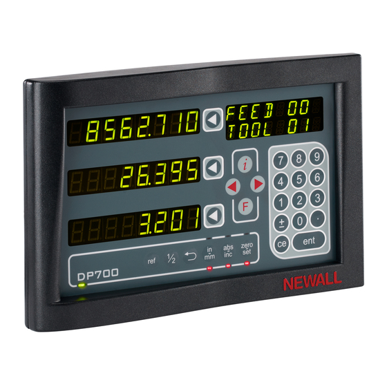
Датчики подключаются к устройству цифровой индикации DP700 той же фирмы. Документация на нее, естественно, все так же не отличается полнотой, распиновки разъемов нет. Выглядит девайс так:

На тыльной стороне имеется несколько (в зависимости от модификации) разъемов D-Sub-9 для подключения датчиков. К этим разъемам я и подключал осциллограф посредством самодельной платки-переходника. Фото:

После измерений, получили следующее. Для начала, распиновка разъема:

Вывод 1 (черный провод): синусоида — несущая частота.

Вывод 2 (жёлтый провод): счетные импульсы, полученные амплитудной модуляцией.

Вывод 3 (красный провод): питание +12 В.
Вывод 4 (белый провод): синусоида, возможно, наводка от несущей.

Вывод 5 (зеленый провод): питание 0 В.
Вывод 6 (не используется).
Вывод 7 (серый провод): постоянное напряжение +1,6 В.
Вывод 8 (оранжевый провод): постоянное напряжение +3,0 В.
Вывод 9 (фиолетовый провод): постоянное напряжение +3,6 В.
Экран кабеля прикручен к корпусу датчика.
Назначение выводов 4, 7, 8 и 9 не ясно, но полученной по другим выводам информации хватает для анализа работоспособности датчиков. Однако, простой вариант с подачей питания и мониторингом сигналов осциллографом не работает, т.к. необходимо подключение УЦИ, от которой и поступает несущая частота на вывод 1.
В моем случае оба датчика оказались исправными, вышло из строя само УЦИ DP700. Индикация не реагировала на кнопки, постоянно сбивалась со счета, выдавая сообщение «no Sig». После вскрытия её корпуса, обнаружился раскаленный микроконтроллер STM32F100VCT6B. Программатора подходящего под рукой не оказалось, на чем история и закончилась. Хотя… ST-Link V2 у китайцев стоит 130 р. Шансы, что МК поделится прошивкой околонулевые, но попробовать можно.

Вне зависимости от дальнейшей судьбы УЦИ, полученная инфа по ньюволовским железкам в будущем может оказаться полезной. Надеюсь, не только для меня.
| Наименование параметров | Newall DPA 700 | |
|---|---|---|
| Количество осей | 2 или 3 оси | |
| Фрезерный станок | Токарный станок | |
| Выбор направления отсчета |

|
|
| Поиск абсолютных координат |
|
|
| Поиск центра |
|
|
| Радиус / диаметр |
|
|
| Абсолютные / относительные координаты |
|
|
| Миллиметры / дюймы |
|
|
| Установка нулевой точки |
|
|
| Оповещение при приближении к нулю |
|
|
| Память на 99 инструментов |
|
|
| Конус |
|
|
| Суммирование осей |
|
|
| Расчет положения отверстий по кругу |
|
|
| Полярные координаты |
|
|
| Расчет положения отверстий по прямой |
|
|
| Удержание данных |
|
|
| Отображение скорости перемещения |
|
|
| Выход RS232 |
|
|
| Линейная компенсация ошибок |
|
|
| Сегментная компенсация ошибок |
|
|
| Класс защиты |
IP 40 (головное устройство) IP 54 (линейка) |
|
| Измерительные линейки | Spherosyn и Microsyn | |
| Язык интерфейса | английский, французский, немецкий, русский, итальянский, турецкий, чешский,португальский, датский |
Доставляем ушедшие из РФ бренды напрямую из США и Европы. Есть вопросы? Напишите нам в WhatsApp!
×
Сейчас вы находитесь в городе Москва
Выберите город, в который Вы хотите осуществить доставку
×
Почему у нас дешевле?
![]() Наша компания доставляет товары напрямую из США и Европы. Мы сотрудничаем с официальными поставщиками и производителями брендов.
Наша компания доставляет товары напрямую из США и Европы. Мы сотрудничаем с официальными поставщиками и производителями брендов.
![]() В нашем каталоге вы найдете уникальный ассортимент, большинство товаров не продаются в России. За счет прямой логистики до вашего адреса вы не переплачиваете цепочке посредников и конечная цена товара выходит значительно дешевле, чем стоимость в обычном магазине в РФ.
В нашем каталоге вы найдете уникальный ассортимент, большинство товаров не продаются в России. За счет прямой логистики до вашего адреса вы не переплачиваете цепочке посредников и конечная цена товара выходит значительно дешевле, чем стоимость в обычном магазине в РФ.
![]() Покупая на Shopozz, вы можете не сомневаться, что получите оригинальный товар высокого качества по минимальной цене.
Покупая на Shopozz, вы можете не сомневаться, что получите оригинальный товар высокого качества по минимальной цене.
Доставка в
город Москва
: 4 октября
Вопрос по товару?
Мы перезвоним!
Основные характеристики
Оригинальное название:
Newall DP700 3 Axis Digital Readout DRO Display for Milling
Товар из США
Доставим в Ваш город
Артикул:302313358895
Продавец:
ezbayestore
(702)
Местонахождение:Rochester, New York, US
Доставка до склада США
Бесплатно

Товары из магазинов
США и Европы
без наценок!
Отправили
67 000 посылок
с 2008 года!
Знаменитый
каталог eBay
на русском языке!
Доставка курьером
до двери
Почтой или в удобный пункт выдачи!
Newall DP700 3 Axis Digital Readout DRO Display for Milling
Newall DP700 3 Axis Digital Readout DRO Display for Milling – можно купить на shopozz.ru с доставкой
из Rochester, New York, US. Все товары из
категории «Другой» быстро и вовремя доставляются в Россию и страны СНГ.
Полную информацию о доставке можно посмотреть в разделе «Доставка».
На товары категории «Другой» действует доступная цена,
поэтому Newall DP700 3 Axis Digital Readout DRO Display for Milling можно
приобрести всего за
274621 руб.
Не можете сделать выбор? Посмотрите другие товары продавца
ezbayestore
(702)
–
«Смотреть все товары».
Возникли вопросы о товаре, условиях оплаты либо доставки?
Закажи обратный
звонок!
Другие бренды категории
Покупки в США и Европе — это просто
Вы делаете заказ — мы выкупаем товары и доставляем вам
Склад

$46
Косметика M.A.C.maccosmetics.com

$46
Часы Timexamazon.com

$15
Джинсы levi’sebay.com
К вам домойОтправляем в Россию и
во все страны СНГ
Начать выгодные покупки в зарубежных интернет-магазинах