-
Contents
-
Table of Contents
-
Troubleshooting
-
Bookmarks
Quick Links
Cat. No. I011-E1-3
USER’S MANUAL
SYSDRIVE 3G3EV
(Standard Models)
Compact Low-noise Inverter
Related Manuals for Omron SYSDRIVE 3G3EV
Summary of Contents for Omron SYSDRIVE 3G3EV
-
Page 1
Cat. No. I011-E1-3 USER’S MANUAL SYSDRIVE 3G3EV (Standard Models) Compact Low-noise Inverter… -
Page 2
Thank you for choosing this SYSDRIVE 3G3EV-series product. Proper use and handling of the product will ensure proper product performance, will length product life, and may prevent possible accidents. Please read this manual thoroughly and handle and operate the product with care. -
Page 3: Table Of Contents
Table of Contents Chapter 1. Getting Started ……Items to be Checked when Unpacking ……Precautions .
-
Page 4
Table of Contents Chapter 5. Operation ……Protective and Diagnostic Functions . -
Page 5: Chapter 1. Getting Started
Chapter 1 Getting Started 1-1 Items to be Checked when Unpacking 1-2 Precautions…
-
Page 6: Items To Be Checked When Unpacking
1-1 Items to be Checked when Unpacking H Checking the Product On delivery, always check that the delivered product is the SYSDRIVE 3G3EV Inverter that you ordered. Should you find any problems with the product, immediately contact your nearest local sales representative.
-
Page 7: Precautions
Chapter 1 Getting Started Voltage Class Special Specification Three-phase 200-VAC input English Models Single/Three-phase 200-VAC -CUE UL/CUL and EC Directives input Models Blank Japanese Models Installation Type/Option Panel mounting Option D Checking for Damage Check the overall appearance and check for damage or scratches resulting from trans- portation.
-
Page 8
Chapter 1 Getting Started If an inspection or some other task is to be performed, always wait at least one minute from the time all indicators on the front panel go off. (Note that this warning is applicable whenever you perform any task after turning the main circuit off.) H Do Not Remove the Digital Operator When the Main Circuit is Still On. -
Page 9: Chapter 2. Overview
Chapter 2 Overview 2-1 Features 2-2 Component Names…
-
Page 10: Features
Chapter 2 Overview 2-1 Features H Easy to Use D Basic Constants Displayed On Indicators Constants for basic operations such as frequency setting and acceleration/deceleration time setting are displayed on dedicated indicators. Therefore, constant numbers can be confirmed easily. D Minimum Constant Setting Items Constant setting items have been minimized to enable even first-time users to set constants easily.
-
Page 11
Chapter 2 Overview H Easy to Wire D Easy Wiring without Having to Open the Front Cover This Inverter can be wired just by opening the terminal block cover. D Separate Input and Output Terminal Blocks Power input terminals are located in the upper section, while motor output terminals are in the lower section. -
Page 12: Component Names
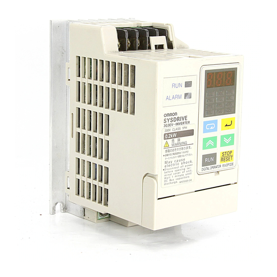
Chapter 2 Overview 2-2 Component Names H Main Unit Main Circuit Terminals (Input) Power input Braking resistor terminals connection terminals L1 N/L2 L3 Run indicator Digital Operator Alarm indicator Control circuit terminals Control circuit (output) terminals (input) SF SR S1 SC FS FR FC Ground terminal Motor output terminals…
-
Page 13: Digital Operator
Chapter 2 Overview H Digital Operator Data display section Monitor item indicators In-service item indicators (green indicators) Display These items can be monitored or set even section during operation. Stopped item indicators (red indicators) These items can be set only when the Inverter is stopped.
-
Page 14: Chapter 3. Design
Chapter 3 Design 3-1 Installation 3-2 Wiring…
-
Page 15: Installation
Chapter 3 Design 3-1 Installation 3-1-1 Outside/Mounting Dimensions Note All dimensions are in millimeters. H 3G3EV-A2001(-j) to 3G3EV-A2004(-j) (0.1 to 0.4 kW): Three-phase 200-VAC Input H 3G3EV-AB001(-j) to 3G3EV-AB002(-j) (0.1 to 0.2 kW): Single/Three-phase 200-VAC Input 4.5 dia. Note 1. For the 3G3EV-A2001(-j), 3G3EV-A2002(-j), and 3G3EV-AB001(-j), a U- shaped notch (4.5 mm wide) is provided instead of the upper mounting hole (4.5 mm in diameter).
-
Page 16
Chapter 3 Design D Three-phase 200-VAC Input Model 3G3EV Output Weight model (kg) A2001(-j) 0.1 kW Approx. A2002(-j) 0.2 kW Approx. A2004(-j) 0.4 kW Approx. D Single/Three-phase 200-VAC Input Model 3G3EV Output Weight model (kg) AB001(-j) 0.1 kW Approx. AB002(-j) 0.2 kW Approx. -
Page 17: Installation Conditions
Chapter 3 Design Note Install the Inverter with four M4 bolts. D Three-phase 200-VAC Input Model 3G3EV Output Weight (kg) model A2007(-j) 0.75 kW Approx. 1.3 A2015(-j) 1.5 kW Approx. 1.5 D Single/Three-phase 200-VAC Input Model 3G3EV Output Weight model (kg) 0.4 kW Approx.
-
Page 18
Chapter 3 Design •Install the Inverter in a clean location free from oil mist and dust. Alternatively, install it in a totally enclosed panel that is completely shielded from suspended dust. •When installing or operating the Inverter, always take special care so that metal pow- der, oil, water, or other foreign matter do not get in the Inverter. -
Page 19: Wiring
Chapter 3 Design 3-2 Wiring 3-2-1 Terminal Blocks H Name of Each Terminal Block Main Circuit Terminals (Input) Power input Braking resistor terminals connection terminals Control circuit terminals (output) Control circuit terminals (input) SF SR S1 SC FS FR FC Ground Main circuit terminals terminal…
-
Page 20: Main Circuit Terminals
Chapter 3 Design H Main Circuit Terminals D Input Terminals (Top Section) Terminal Name and description symbol R (L1) Power input terminals A2j: Three-phase 200 to 230 VAC, 50/60 Hz A2j: Three-phase 200 to 230 VAC, 50/60 Hz S (L2/N) ABj: Single-phase 200 to 240 VAC, 50/60 Hz Three-phase 200 to 230 VAC, 50/60 Hz A4j: Three-phase 380 to 460 VAC, 50/60 Hz…
-
Page 21: Control Circuit Terminals
Chapter 3 Design H Control Circuit Terminals D Input Terminals (On Right-hand Side) No external power supply is required because a built-in power supply is provided. Terminal Name and description Interface symbol Forward/Stop When the terminal is ON, the motor rotates in the forward direction.
-
Page 22: Standard Connection Diagram
Chapter 3 Design D Output Terminals (On Left-hand Side) Terminal Name and description Interface symbol Multi-function contact output (contact a) (see note) Multi-function contact output (contact b) 30 VDC (see note) 250 VAC Multi-function contact output (common) Note Constant No. 09 (n09) is used to set the function. This constant is factory set to “operation in progress.”…
-
Page 23: Wiring Around The Main Circuit
Chapter 3 Design Note 1. If a 3G3EV-ABjjj is used in single-phase input mode, single-phase 200 to 240 VAC power with a frequency of 50/60 Hz must be input between terminals R and S. Note 2. For the 3-wire sequence, refer to the wiring on page 4-12. Note 3.
-
Page 24
Chapter 3 Design Determining the Wire Size Determine the wire size for the main circuit so that line voltage drop is within 2% of the rated voltage. Line voltage drop V is calculated as follows: –3 (V) = 3 x wire resistance (Ω/km) x wire length (m) x amperage (A) x 10 H Wiring on the Input Side of Main Circuit D Installing a Molded-case Circuit Breaker Always connect the power input terminals (R, S, and T) and power supply via a molded-… -
Page 25
Chapter 3 Design D Installing an AC Reactor If the Inverter is connected to a large-capacity power transformer (600 kW or more) or the phase advance capacitor is switched, an excessive peak current may flow through the input power circuit, causing the converter unit to break down. To prevent this, install an optional AC reactor on the input side of the Inverter. -
Page 26
Chapter 3 Design D Installing a Noise Filter on the Power Supply Side Install a noise filter to eliminate noise transmitted between the power line and the Inverter. Wiring Example 1 Power 3G3IV-PHF 3G3EV supply Noise filter SYSMAC, etc. Other controllers Note Use a special-purpose noise filter for Inverters. -
Page 27
Chapter 3 Design D Never Connect Power Supply to Output Terminals Caution Never connect a power supply to output terminals U, V, and W. If voltage is applied to the output terminals, the internal mechanism of the Inverter will be damaged. D Never Short or Ground the Output Terminals Caution If the output terminals are touched with bare hands or the output wires come into contact with the Inverter casing, an electric shock or grounding will occur. -
Page 28
Chapter 3 Design Induction Noise: Electromagnetic induction generates noise on the signal line, causing the controller to malfunction. Radio Noise: Electromagnetic waves from the Inverter and cables cause the broadcasting radio receiver to make noise. D How to Prevent Induction Noise As described above, a noise filter can be used to prevent induction noise from being generated on the output side. -
Page 29: Ground Wiring
Chapter 3 Design D Cable Length between Inverter and Motor If the cable between the Inverter and the motor is long, the high-frequency leakage cur- rent will increase, causing the Inverter output current to increase as well. This may affect peripheral devices.
-
Page 30: Wiring Control Circuit Terminals
Chapter 3 Design 3-2-3 Wiring Control Circuit Terminals The control signal line must be 50 m or less and must be separated from the power line. If frequency references are input externally, use a twisted- pair shielded line. H Wiring Sequence Input/Output Terminals Wire the sequence input terminals (SF, SR, S1, and SC) and the multi-function contact output terminals (MA, MB, and MC) as described below.
-
Page 31
Chapter 3 Design D Wires to be Used Always use twisted-pair shielded wires to prevent malfunctions due to noise. Wire type Wire size Wire to be used Single wire 0.5 to 1.25 mm Polyethylene-insulated cable for instrumentation (with shield) Stranded wire 0.5 to 1.25 mm D Wiring Method •The wiring procedure is the same as for sequence input/output terminals, described… -
Page 32: Chapter 4. Preparing For Operation
Chapter 4 Preparing for Operation 4-1 Preparation Procedure 4-2 Using the Digital Operator 4-3 Test Run…
-
Page 33: Preparation Procedure
Chapter 4 Preparing for Operation 4-1 Preparation Procedure 1. Installation: Install the Inverter according to installation conditions. Refer to page 3-2 Check that all the installation conditions are met. 2. Wiring: Connect the Inverter to power supply and peripheral devices. Refer to page 3-6 Select peripheral devices that meet the specifications, and wire them correctly.
-
Page 34: Using The Digital Operator
Chapter 4 Preparing for Operation 6. Test Run: Perform a no-load test run and an actual loading test run to check that the motor and peripheral devices operate normally. Refer to page 4-25 Check the direction of motor rotation and check that the limit switches operate nor- mally.
-
Page 35
Chapter 4 Preparing for Operation H Function of Each Component D Display Sections Data display section Reference frequency values, output frequency values, output current values, constant settings, and error codes are displayed. Monitor item indicators When this indicator is lit, an output frequency value (Hz) is displayed in the data display section. -
Page 36: Outline Of Operation
Chapter 4 Preparing for Operation 4-2-2 Outline of Operation H Switching Data Display during Operation Press the Mode Key to switch data display. During operation, only the items in the in-service item indicators section can be monitored and the constants for these items can be set. If the power is turned off when the FOUT or IOUT indicator is lit, the same indicator lights up next time the power is turned on.
-
Page 37
Chapter 4 Preparing for Operation H Switching Data Display when Inverter is Stopped Press the Mode Key to switch data display. When the Inverter is stopped, all items can be monitored and the constant for each item can be set. Example Indi- Description… -
Page 38
Chapter 4 Preparing for Operation H Monitor Display The 3G3EV allows the user to monitor the reference frequency, output fre- quency, output current, and the direction of rotation. D Operation Method Indicator Example of Description operation data display 60.0 Press the Mode Key until the FREF indicator lights up. -
Page 39: Setting Constants
Chapter 4 Preparing for Operation 4-2-3 Setting Constants The 3G3EV (Standard Model) allows the user to set 18 different constants. The constants for basic operations are allocated to dedicated indicators, so the user need not refer to the constant nos. The constants allocated to dedicated indicators can be also set by lighting the PRGM indicator.
-
Page 40
Chapter 4 Preparing for Operation D Setting Constants Using the PRGM Indicator Example: Changing the value of constant no. 02 (operation mode selection) to “2.” Indicator Example of Explanation operation data display Press the Mode Key until the PRGM indicator lights up. -
Page 41
Chapter 4 Preparing for Operation H List of Constants Constant Dedicated Description Setting range Factory setting indicator Constant write-inhibit selec- 0, 1, 8, 9 tion/constant initialization Operation mode selection 0 to 5 Interruption mode selection 0, 1 Forward/reverse rotation For, rEv selection Multi-function input selec- 0 to 4… -
Page 42
Chapter 4 Preparing for Operation Note 3. The setting range for the 400-VAC models is “1 to 5.” Note 4. The factory setting for the 3G3EV-A4015-CUE is “3.” Note 5. Displaying the constant no. corresponding to an indicator in the “Dedicated indicator”… -
Page 43
Chapter 4 Preparing for Operation Example of 3-wire Sequence Mode Stop switch switch (contact b) (contact a) Run command (starts Inverter when “closed”) Stop command (stops Inverter when “opened”) Forward/Reverse rotation command (rotates motor in forward direction when “opened”; rotates motor in reverse direction when “closed”) Common Example of Operation Forward rotation… -
Page 44
Chapter 4 Preparing for Operation Note 2. The DIP switch is located inside the Inverter. Use this switch to change the set- ting when frequency references are to be input in terms of amperage (4 to 20 mA). For details, refer to Section 7-2 Frequency Reference by Amperage Input. For voltage input, never set the DIP switch to ON. -
Page 45
Chapter 4 Preparing for Operation Forward/Reverse Rotation Selection f%r , reU Factory setting f%r Setting range (forward rota- tion) This constant is used to specify the direction of motor rotation when the Inverter is oper- ated with the Digital Operator. Value Description Forward rotation… -
Page 46
Chapter 4 Preparing for Operation Note MA is turned on when the difference between the reference frequency and the output frequency falls within 2 Hz. MA is turned off when the difference exceeds ±4 Hz. Example of Operation Reference frequency Detection range ±2 Hz Release range… -
Page 47
Chapter 4 Preparing for Operation Frequency Reference 1 Setting range 0.0 to 400 (Hz) Factory setting 6.0 (Hz) Frequency Reference 2 Setting range 0.0 to 400 (Hz) Factory setting 0.0 (Hz) •These constants are used to set reference frequency values. •The unit of setting is as follows: 0.0 to 99.9 (Hz): 0.1 (Hz) 100 to 400 (Hz): 1 (Hz) -
Page 48
Chapter 4 Preparing for Operation Acceleration Time Setting range 0.0 to 999 Factory setting 10.0 (seconds) (seconds) Deceleration time Setting range 0.0 to 999 Factory setting 10.0 (seconds) (seconds) •These constants are used to set acceleration time (required to increase the output fre- quency from the stopped state to the maximum frequency) and deceleration time (re- quired to decrease the output frequency from the maximum frequency to the stopped state). -
Page 49
Chapter 4 Preparing for Operation Maximum Frequency Setting range 50.0 to 400 Factory setting 60.0 (Hz) (Hz) Unit of setting 50.0 to 99.9 (Hz) : 0.1 (Hz) 100 to 400 (Hz) : 1 (Hz) Maximum Voltage Setting range 1 to 255 (510) Factory setting 200 (400) (V) Unit of setting 1 (V) Maximum Voltage Frequency (Basic Frequency) -
Page 50
Chapter 4 Preparing for Operation Electronic Thermal Reference Current Setting range 0.0 to Factory setting See note 2 (see note 1) (A) Unit of setting 0.1 (A) •This constant is used to set an electronic thermal reference value to protect the motor from overheating. -
Page 51
Chapter 4 Preparing for Operation Operation after Recovery from Power Interruption Setting range 0, 1, 2 Factory setting 0 This constant is used to select the processing to be performed after recovery from an instantaneous power interruption. Value Description Discontinues operation. Continues operation only if power interruption is within 0.5 second. -
Page 52
Chapter 4 Preparing for Operation Note 2. The factory setting for the 3G3EV-A4015-CUE is “3.” Note 3. With the 400-VAC class, the continuous output current cannot be used to 100% of the rated value if the constant is set to “5” for Inverters of 0.75 kW or less or if it is set to “4”… -
Page 53
Chapter 4 Preparing for Operation Frequency Reference Gain Setting range 0.10 to 2.55 Factory setting 1.00 (times) (times) Unit of setting 0.01 (times) Frequency Reference Bias Setting range –99 to 99 (%) Factory setting 0 (%) Unit of setting 1 (%) •These constants are used to set the relationship between analog voltage and refer- ence frequencies when frequency references are input through control terminals FR and FC. -
Page 54
Chapter 4 Preparing for Operation Stop Key Selection Setting range 0, 1 Factory setting 0 •When inputting Inverter operation from the control terminals, the Stop Key on the Digi- tal Operator can be set to “enabled” or “disabled.” Value Description Stop Key enabled Stop Key disabled Note 1. -
Page 55
Chapter 4 Preparing for Operation •Recorded are Inverter errors and other errors that actuate a protective mechanism. Warning (automatically recovered error) is not recorded. •If no error has occurred, the indicator is not lit. •All error codes are listed below. Error code Description Error category… -
Page 56: Test Run
Chapter 4 Preparing for Operation 4-3 Test Run After wiring is complete, perform a test run of the Inverter as follows. First, start the motor through the Digital Operator without connecting the motor to the mechanical system. Next, connect the motor to the mechanical sys- tem and perform a test run.
-
Page 57: Setting Rated Motor Amperage
Chapter 4 Preparing for Operation 4-3-5 Setting Rated Motor Amperage •Set the rated motor amperage in constant no. 31 (electronic thermal reference current) or with the “THR” indicator lit. 4-3-6 Setting the Reference Frequency •Set the frequency corresponding to the motor speed in constant no. 11 (frequency ref- erence 1) or with the “FREF”…
-
Page 58: Chapter 5. Operation
Chapter 5 Operation 5-1 Protective and Diagnostic Functions 5-2 Troubleshooting 5-3 Maintenance and Inspection…
-
Page 59: Protective And Diagnostic Functions
Chapter 5 Operation 5-1 Protective and Diagnostic Functions The 3G3EV has excellent protective and diagnostic functions. The RUN and ALARM indicators on the front panel indicate the current Inverter sta- tus, and the data display section also displays information about an error that has occurred.
-
Page 60
Chapter 5 Operation H Data Display and Action to be Taken when Warning Status Arises The ALARM indicator flashes when warning status arises. The data display section also flashes. When warning status arises, no error code is output. Eliminating the cause recovers the system automatically. Data Description Action… -
Page 61
Chapter 5 Operation H Data Display and Action to be Taken when Protective Mechanism is Actuated The ALARM indicator lights up when the protective mechanism is actuated. In this event, Inverter output is shut off, and the motor coasts to a stop. Check the cause of the error, take the necessary action, and perform fault reset or turn the power off, then on. -
Page 62
Chapter 5 Operation Data Description Cause and action display • The input power voltage dropped. Main circuit undervoltage (UV1) • Open-phase occurred. The DC voltage of the main circuit dropped below the specified level. • An instantaneous power interruption 3G3EV-A2jjj: Approximately 200 V occurred. -
Page 63
Chapter 5 Operation Data Description Cause and action display • Review the load size, V/f characteris- Motor overload (OL1) tics, acceleration/deceleration time, The electronic thermal relay actuated and cycle time. the motor overload protection function. • Set the rated motor amperage in constant No. -
Page 64
Chapter 5 Operation H Data Display and Action to be Taken when Inverter Error Occurs The first character of an error code is always “F” when an Inverter error occurs. (Howev- er, all indicators are not lit when a control circuit error occurs.) If an Inverter error occurs, turn the power off, then on. -
Page 65: Troubleshooting
Chapter 5 Operation 5-2 Troubleshooting If the Inverter or motor does not operate properly when the system is started, constant settings or wiring may be incorrect. In this case, take the appropriate action as described below. (If an error code is displayed, refer to 5-1 Protective and Diagnostic Functions.) 5-2-1 Constants Fail to Set H err is Displayed in the Data Display Section.
-
Page 66: Motor Rotates In The Wrong Direction
Chapter 5 Operation •The reference frequency is too low. When the reference frequency is less than 1.5 Hz, the Inverter cannot operate. Change the reference frequency to 1.5 Hz or more. •The sequence input method is wrong. If the 3-wire sequence input mode is selected as an external terminal function instead of the actual 2-wire sequence input mode, the motor will not run, in which case change the constant or change to the sequence input that matches the constant setting.
-
Page 67: Motor Deceleration Is Too Slow
Chapter 5 Operation To reverse the direction of rotation, switch the wires of two phases of U, V, and W as shown below. Inverter Motor Forward rotation Reverse rotation 5-2-4 Motor Deceleration is Too Slow H Deceleration Time is Too Long Even if a Braking Resistor is Connected.
-
Page 68: Motor Burns
Chapter 5 Operation 5-2-6 Motor Burns •The dielectric strength of the motor is insufficient. Surge arises when the motor (inductive load) is connected to the output side of the Inverter. Normally, the maximum surge voltage is approximately three times the power voltage.
-
Page 69: Mechanical System Makes Noise
Chapter 5 Operation S Install an input noise filter. Install an input noise filter (3G3IV-PHF) on the power input side of the Inverter. S Install an output noise filter. Install an output noise filter (3G3IV-PLF) on the output side of the Inverter. S Use metal box and piping.
-
Page 70: Maintenance And Inspection
Chapter 5 Operation Under the wiring condition shown below, if the control output power supply is lower than 24 VDC or if it is set to OFF, current may flow in the direction shown by the arrows and may operate the Inverter input. In such a case, insert a diode in the A section shown below.
-
Page 71
Chapter 5 Operation H Regular Maintenance Check the items below during regular maintenance. Before starting inspection, always turn the power off, then wait at least one minute after all indicators on the front panel go off. Touching terminals immediately after turning the power off may cause an electrical shock. -
Page 72: Chapter 6. Specifications
Chapter 6 Specifications 6-1 Specifications of Main Unit…
-
Page 73
Chapter 6 Specifications 6-1 Specifications of Main Unit H Rating Model 3G3EV- A2001(-j) A2002(-j) A2004(-j) A2007(-j) A2015(-j) Three phase, Power Rated voltage Three-phase, 200 to 230 VAC, 50/60 Hz 200 VAC supply and frequency Allowable –15% to 10 % voltage fluctuation ±5% Allowable… -
Page 74: General Specifications
Chapter 6 Specifications Model 3G3EV- Three A4002(-j) A4004(-j) A4007(-j) A4015(-j) phase, Power Rated voltage Three-phase, 380 to 460 VAC, 50/60 Hz 400 VAC supply and frequency Allowable –15% to 10 % voltage fluctuation ±5% Allowable frequency fluctuation Heating value (W) 25.5 34.7 56.0…
-
Page 75
Chapter 6 Specifications H Control Characteristics Control method Sine-wave PWM method (automatic torque boost) Frequency control 1.5 to 400 Hz range Frequency accuracy Digital command: ±0.01% (–10°C to 50°C) (temperature fluctuation) Analog command: ±1% (25 ±10°C) Frequency setting Digital command: resolution 0.1 Hz (less than 100 Hz), 1 Hz (100 Hz or more) Analog command:… -
Page 76: Protection Functions
Chapter 6 Specifications H Protection Functions Motor protection Electronic thermal protection Instantaneous When 250% of the rated output amperage is exceeded overcurrent protection Overload protection When 150% of the rated output amperage is exceeded for one minute Overvoltage protection Stops the system when DC voltage of the main circuit exceeds approximately 410 V (400-VAC Class approximately 820 V) Voltage drop protection 3G3EV-A2jjj: Stops the system when voltage drops below approximately 200 V…
-
Page 77
Chapter 6 Specifications H Operation Specifications Three photocoupler input terminals (24 VDC, 8 mA) Control input • Forward/stop [SF] • Reverse/stop [SR] • Multi-function input [S1] (set in constant No. 06) Select either of “fault reset,” “external fault,” and “multi-step speed command.”… -
Page 78: Chapter 7. Appendix A
Chapter 7 Appendix A 7-1 Notes on Using Inverter for Motor 7-2 Frequency Reference by Amperage Input 7-3 List of Product Models…
-
Page 79: Notes On Using Inverter For Motor
Chapter 7 Appendix A 7-1 Notes on Using Inverter for Motor H Using Inverter for Existing Standard Motor When a standard motor is operated with this Inverter, a power loss is slightly higher than when operated with a commercial power supply. In addition, cooling effects also decline in the low-speed range, resulting in an increase in the motor temperature.
-
Page 80
Chapter 7 Appendix A D Vibration The 3G3EV series employs high carrier PWM control to reduce motor vibration. When the motor is operated with this Inverter, motor vibration is almost the same as when op- erated with a commercial power supply. However, motor vibration may become greater in the following cases: •Resonance with the natural frequency of mechanical system Take special care when a machine that has been operated at a constant speed is to… -
Page 81: Frequency Reference By Amperage Input
Chapter 7 Appendix A D Gearmotor The speed range for continuous operation differs according to the lubrication method and motor manufacturer. In particular, continuous operation of an oil-lubricated motor in the low speed range may result in burning. If the motor is to be operated at a speed high- er than 60 Hz, consult with the manufacturer.
-
Page 82
Chapter 7 Appendix A 3. Removing the Digital Operator S Insert a finger in the recessed section below the Digital Operator, then lift the under- neath of the Digital Operator. S When the connector comes off, grip the lower edges of the Digital Operator, and slide it down until it comes off. -
Page 83
Chapter 7 Appendix A “SW1” is marked near the switch. Switch indicator V: Voltage input I: Amperage input DIP switch 5. Changing the DIP switch setting To use amperage input mode, set this switch to ON by sliding it to the right. (factory setting) 6. -
Page 84: List Of Product Models
Chapter 7 Appendix A 7-3 List of Product Models H Inverter Specifications Model Standard Three-phase 200 VAC input 0.1 kW 3G3EV-A2001(-j) models 0.2 kW 3G3EV-A2002(-j) 0.4 kW 3G3EV-A2004(-j) 0.75 kW 3G3EV-A2007(-j) 1.5 kW 3G3EV-A2015(-j) Single/Three-phase 200 VAC input 0.1 kW 3G3EV-AB001(-j) 0.2 kW 3G3EV-AB002(-j)
-
Page 85: Output Noise Filter
Chapter 7 Appendix A H Braking Resistor (Duty Cycle 3% ED) Specifications Model 400 Ω 200-VAC class 0.1 kW/0.2 kW 3G3IV-PERF150WJ401 200 Ω 0.4 kW/0.75 kW 3G3IV-PERF150WJ201 100 Ω 1.5 kW 3G3IV-PERF150WJ101 750 Ω 400-VAC class 0.75 kW or less 3G3IV-PERF150WJ751 400 Ω…
-
Page 86
Chapter 7 Appendix A H DIN Track Specifications Model 3G3EV-A2001(-j) to 3G3EV-A2004(-j) 3G3EV-PSPAT3 3G3EV-AB001(-j) and 3G3EV-AB002(-j) 3G3EV-A2007(-j) to 3G3EV-A2015(-j) 3G3EV-PSPAT4 3G3EV-AB004(-j) and 3G3EV-AB007(-j) 3G3EV-A4002(-j) to 3G3EV-A4007(-j) -
Page 87
Chapter 7 Appendix A List of Constants Used with 3G3EV Standard Model Constant Indi- Description Setting range Setting cators Constant 0: Only n01 can be set. write-inhibit 1: All constants can be set. selection 8: Constant settings are initialized. /constant 9: Inverter is initialized in 3-wire initialization sequence mode. -
Page 88
Chapter 7 Appendix A Constant Indi- Description Setting range Setting cators Deceleration 0.0 to 999 (seconds) [10.0] time Maximum 50.0 to 400 (Hz) [60.0] frequency Maximum 1 to 255 (V) (see note 1) [200] voltage Maximum 1.6 to 400 (Hz) [60.0] voltage frequency (basic…
This manual is also suitable for:
Sysdrive 3g3ev series
USERS MANUAL
(SYSMAC BUS Model)
Compact Low-noise Inverter
SYSDRIVE 3G3EV SERIES
Thank you for choosing this SYSDRIVE 3G3EV-series product. Proper use and handling of the product will ensure proper product performance, will lengthen product life, and may prevent possible accidents. Please read this manual thoroughly and handle and operate the product with care.
NOTICE 1. This manual describes the functions of the product and relations with other
products. You should assume that anything not described in this manual is not possible.
2. Although care has been given in documenting the product, please contact your OMRON representative if you have any suggestions on improving this manual.
3. The product contains potentially dangerous parts under the cover. Do not attempt to open the cover under any circumstances. Doing so may result in injury or death and may damage the product. Never attempt to repair or dis- assemble the product.
4. We recommend that you add the following precautions to any instruction manuals you prepare for the system into which the product is being installed. Precautions on the dangers of high-voltage equipment.
Precautions on touching the terminals of the product even after power has been turned off. (These terminals are live even with the power turned off.)
5. Specifications and functions may be changed without notice in order to im- prove product performance.
Items to Check Before Unpacking Check the following items before removing the product from the package:
Has the correct product been delivered (i.e., the correct model number and specifications)?
Has the product been damaged in shipping?
Are any screws or bolts loose?
!» #
$ %
& ‘ %
$ ( » )
$ & %
$ & & *
+ , & —
#
. /
. %
, )
! $ (
$
. & # *
& 0 —
$ —
& #1 —
2 — —
, 3!. —
+ , 0 » ( —
% , 0. 41 —
* 5 #
6 41 (
) 05 0
— » ,1
. 1
+ 5 # +
+ & +6
+ , +6
+ » #1 » 7 +6
+ » #1 0 ! / +)
+ » #1 0 ! / +)
++ » +)
+% » 0 $ # +-
+* » # & , +-
+6 38 9 # ‘ ( +
+) » ‘ +
+- 05 5 , +
+ (» 0 05 5 , +
+ : ( 5 , +
+ » ,1 » +
+ » +
!!
% ,. . » %
» #$% &$ «
* 5 . » *
* 9 . » *+
1-1 Items to be Checked when Unpacking
Checking the Product On delivery, always check that the delivered product is the SYSDRIVE 3G3EV Inverter that you ordered.
Should you find any problems with the product, immediately contact your nearest local sales representative.
Checking the Nameplate
Inverter model Input specifications
Output specifications
R
Checking the Model 3G3EV-A2002R
Specifications
Maximum applicable motor capacity
Voltage class
Installation type
Series name: 3G3EV Series
Specifications Blank Standard model R SYSMAC BUS model
Maximum Applicable Motor Capacity 001 0.1 kW 002 0.2 kW 004 0.4 kW 007 0.75 kW 015 1.5 kW
Voltage Class
2 Three-phase 200 VAC input B Single/Three-phase 200 VAC
input
Installation Type
A Panel mounting P Option
Checking for Damage Check the overall appearance and check for damage or scratches resulting from trans- portation.
Chapter 1
Checking Accessories Note that this manual is the only accessory provided with the 3G3EV (SYSMAC BUS Model). Set screws and other necessary parts must be prepared by customers.
1-2 Precautions
To ensure safe operation of the 3G3EV, note the following items:
Always Hold the Heat Sink During Removal. When moving the 3G3EV, always hold the heat sink (aluminum portion on the rear of the Unit).
Heat sink
Watch Out for Residual Voltage On Charged Portions After the power is turned off, residual voltage remains in the capacitor inside the Inverter. Therefore, touching terminals immediately after turning the power off may cause an electrical shock.
If an inspection or some other task is to be performed, always wait at least one minute from the time all indicators on the front panel go off.
(Note that this warning is applicable whenever you perform any task after turning the main circuit off.)
Do Not Remove the Digital Operator When the Main Circuit is Still On.
Always turn the main circuit off before removing the digital operator.
Removing the digital operator with the main circuit ON may cause an electrical shock and damage the equipment.
Chapter 1
Do Not Modify Wiring or Check Signals When the Main Circuit is On.
Always turn the main circuit off before modifying wiring or checking signals.
Touching terminals while the main circuit is on may cause an electrical shock and dam- age the equipment.
Do Not Conduct a Dielectric Strength Test. Because the 3G3EV Inverter is an electronic control unit using semiconductor, never conduct a dielectric strength test or an insulation resistance test for the control circuit.
Modify Constant Settings Correctly. Always modify the constant settings according to the procedures described in this manual.
Chapter 1
2-1 Features
Easy to Use
Basic Constants Displayed On Indicators Constants for basic operations such as frequency setting and acceleration/deceleration time setting are displayed on dedicated indicators. Therefore, constant numbers can be confirmed easily.
Easy to Install
Very Small and Lightweight The 3G3EV Inverter is approximately half the size of our Low-noise General-purpose Inverters in terms of volume and weight percentage. This improves space efficiency and operating efficiency (including easier removal).
Optional DIN Track An optional DIN track is available. This DIN track enables the user to mount the 3G3EV Inverter on the DIN track with a one-touch operation.
Chapter 2
Easy to Wire
Using Two-conductor Cables to Minimize Wiring Two-conductor cables (VCTF) enable the Inverter to be connected a higher-level PC.
Easy Wiring without Having to Open the Front Cover This Inverter can be wired just by opening the terminal block cover.
Separate Input and Output Terminal Blocks Power input terminals are located in the upper section, while motor output terminals are in the lower section. In this way, the input and output terminal blocks are separated ac- cording to the contactors, so incorrect wiring can be prevented.
Soldering No Longer Necessary No connector means no soldering.
Easy to Operate
Bitwise Communication Making Programming Easier No special communication program is required. Allocated input and output areas can be used to control the Inverter in a way similar to ordinary I/O Units.
Switching the Operation Mode by Simple Key Operation For example, after a test run is performed using the Digital Operator, it can be easily switched to a production run in communication mode by simple key operation.
Checking a Test Run with Various Monitors Output frequency, output current, and the direction of motor rotation appear in the dis- play section of the Digital Operator, so the mechanical system can be easily monitored during a test run.
Low Noise An insulated gate bipolar transistor (IGBT) power element has been adopted to elimi- nate metallic noise.
High-torque Operation Even in Low Speed Range A torque rate of 150% can be achieved even in a low speed range where output frequen- cy is only 3 Hz. Thus, acceleration time can be reduced.
Chapter 2
2-2 Component Names
Main Unit Main Circuit Terminals (Input) Power input terminals
Braking resistor connection terminals
Run indicator
Alarm indicator
Ground terminal
Main Circuit Terminals (Output)
Motor output terminals
Digital Operator
Control circuit terminals
Transmission indicator
Transmission terminals
End unit setting switch
L1 N/L2 L3 B1 B2
Note This diagram shows the Inverter with all terminal block covers removed.
Chapter 2
Digital Operator
Display section
Operation keys
Mode Key
Increment Key
RUN Key
Data display section
Monitor item indicators
In-service item indicators (green indicators) These items can be monitored or set even during operation.
Stopped item indicators (red indicators) These items can be set only when the Inverter is stopped.
Constant item indicators
Enter Key
Decrement Key
STOP/RESET Key
Chapter 2
3-1 Installation
3-1-1 Outside/Mounting Dimensions
Note All dimensions are in millimeters.
3G3EV-A2001R to 3G3EV-A2004R (0.1 to 0.4 kW): Three-phase 200-VAC Input
3G3EV-AB001R to 3G3EV-AB002R (0.1 to 0.2 kW): Single/Three-phase 200-VAC Input
4.5 dia.
Note 1. For the 3G3EV-A2001R, 3G3EV-A2002R, and 3G3EV-AB001R, a U-shaped notch (4.5 mm wide) is provided instead of the upper mounting hole (4.5 mm in diameter).
Note 2. Install the Inverter with two M4 bolts.
Chapter 3
Three-phase 200-VAC Input Model 3G3EV model
Output W H D W1 H1 T Weight (kg)
A2001R 0.1 kW 68 128 75 56 118 3 Approx. 0.5
A2002R 0.2 kW 88 3 Approx. 0.6
A2004R 0.4 kW 110 5 Approx. 0.9
Single/Three-phase 200-VAC Input Model 3G3EV model
Output W H D W1 H1 T Weight (kg)
AB001R 0.1 kW 68 128 75 56 118 3 Approx. 0.6
AB002R 0.2 kW 108 5 Approx. 0.9
3G3EV-A2007R to 3G3EV-A2015R (0.75 to 1.5 kW): Three-phase 200-VAC Input 3G3EV-AB004R to 3G3EV-AB007R (0.4 to 0.75 kW): Single/Three-phase 200-VAC Input
Two, 4.5 dia.
Note Install the Inverter with four M4 bolts.
Chapter 3
Three-phase 200-VAC Input Model 3G3EV model
Output W H D W1 H1 Weight (kg)
A2007R 0.75 kW 108 128 130 96 118 Approx. 1.3 A2015R 1.5 kW 155 Approx. 1.5
Single/Three-phase 200-VAC Input Model 3G3EV model
Output W H D W1 H1 Weight (kg)
AB004R 0.4 kW 108 128 130 96 118 Approx. 1.3 AB007R 0.75 kW Approx. 1.3
3-1-2 Installation Conditions
Installation Site Install the Inverter under the following conditions:
Ambient temperature for operation: —10C to 50C Humidity: 90% RH or less (non-condensing)
Install the Inverter in a clean location free from oil mist and dust. Alternatively, install it in a totally enclosed panel that is completely shielded from suspended dust.
When installing or operating the Inverter, always take special care so that metal pow- der, oil, water, or other foreign matter do not get in the Inverter.
Do not install the Inverter on inflammables such as wood.
Direction of Installation Install the Inverter on a vertical surface so that the characters on the nameplate are oriented upward.
Installation Space When installing the Inverter, always provide the following installation space to allow normal heat dissipation from the Inverter:
W= 30 mm min. 100 mm min.
100 mm min.
Air
Side
Air
In ve
rt er
In ve
rt er
In ve
rt er
Chapter 3
Ambient Temperature Control To enhance operation reliability, the Inverter should be installed in an environment free from extreme temperature rises.
If the Inverter is installed in an enclosed environment such as a box, use a cooling fan or air conditioner to maintain the internal air temperature below 50C.
The surface temperature of the Inverter may reach 30C higher than the ambient tem- perature. Therefore, keep all thermally susceptible devices and wires away from the Inverter.
Protecting the Inverter from Foreign Matter during Installation Place a cover over the Inverter to shield it from metal powder produced by drilling dur- ing installation.
(Upon completion of installation, always remove the cover from the Inverter. Other- wise, ventilation will be affected, causing the invert to overheat.)
Chapter 3
3-2 Wiring
3-2-1 Terminal Blocks
Name of Each Terminal Block
Main Circuit Terminals (Input)
Power input terminals
Braking resistor connection terminals
Transmission terminals
Main Circuit Terminals (Output)
Control circuit terminals
Ground terminal Motor output terminals
Note This diagram shows an Inverter with all terminal block covers removed.
Chapter 3
«
Main Circuit Terminals
Input Terminals (Top Section) Terminal symbol
Name and description
L1 N/L2 L3
Power input terminals Three-phase, 200 to 230 VAC, 50/60 Hz input terminals. If a 3G3EV-ABR is to be used in single-phase input mode, single-phase 200 to 240 VAC power with a frequency of 50/60 Hz must be input between terminals R and S.
B1 B2
Braking resistor connection terminals (see note) Terminals for connecting an optional braking resistor
Note Before shipping, a resin plate is attached to each braking resistor connection ter- minal to prevent incorrect wiring. When connecting a braking resistor, always remove the resin plates with a pair of long-nose pliers.
Output Terminals (Bottom Section) Terminal symbol
Name and description
U V W
Motor output terminals Three-phase power output terminals for operating the motor. (Never connect an AC power supply to these terminals.)
Ground terminal Always use a ground terminal with a ground resistance of 100 or less.
6.2 mm max.
Terminal block screw (M3.5)
Crimp terminal
Chapter 3
‘
Control Circuit Terminals
Input Terminals Terminal symbol
Name and description Interface
S1 Multi-function input (see notes 1 and 2)
SC Multi-function input common Input common for S1
24 VDC, 8mA
Note 1. Constant no. 06 (n06) is used to set this function. This constant is factory-set to fault reset.
Note 2. Multi-function input 1 is allocated to both the control circuit terminal and input channel. When either of them is turned on, multi-function input 1 becomes valid. Therefore, if multi-function input 1 is to be used as external fault (contact b), bit 4 of channel n + 1 on the communication side must be set to 0. If this bit is set to 1, an abnormal stop cannot be performed using external terminals.
Output Terminals Terminal symbol
Name and description Interface
PA Multi-function output 1 (see note)
PB Multi-function output common
Max. 48 VDC, 50 mA
Note Constant no. 09 (n09) is used to set the function. This constant is factory-set to operation in progress.
Transmission Terminals Terminal symbol
Name and description
+R Data send-receive terminals —R Terminals used to connect two-conductor cables for SYSMAC BUS.
Note +R and +R, and —R and —R are internally shorted.
Chapter 3
(
Standard Connection Diagram
Power supply: Three-phase, 200 to 230 VAC, 50/60 Hz
Molded-case circuit breaker (MCCB)
Braking resistor (option)
Multi-function input 1
Multi-function input common
Remote I/O Master Unit
Remote I/O (one input channel and one output channel)
Multi-function output 1
Multi-function output common 48 VDC, 50 mA
L1
N/L2
L3
Note 1. If a 3G3EV-ABR is used in single-phase input mode, 200 to 240 VAC power with a frequency of 50/60 Hz must be input between terminals R and S.
Note 2. Use cabtire cables (VCTF 0.75 x 2C) to connect to the Remote I/O Master Unit.
3-2-2 Wiring Around the Main Circuit
System reliability and noise resistance are affected by the wiring method used. Therefore, always follow the instructions given below when connect- ing the Inverter to peripheral devices and other parts.
Wire Size and Molded-Case Circuit Breaker to be Used For the main circuit and ground, always use 600-V polyvinyl chloride (PVC) cables.
Chapter 3
)
If the cable is long and may cause voltage drops, increase the wire size according to the cable length.
Model Terminal symbol
Terminal screw Wire size (mm2)
Molded-case circuit breaker
capacity (A) 3G3EV-A2001R R S T B1 B2 M3.5 0.75 to 2 5 3G3EV-AB001R U V W 3G3EV-A2002R R S T B1 B2 M3.5 0.75 to 2 5 3G3EV-AB002R U V W 3G3EV-A2004R R S T B1 B2 M3.5 0.75 to 2 5 3G3EV-AB004R U V W 3G3EV-A2007R R S T B1 B2 M3.5 0.75 to 2 10 3G3EV-AB007R U V W 3G3EV-A2015R R S T B1 B2 M3.5 0.75 to 2 10
U V W
Determining the Wire Size Determine the wire size for the main circuit so that line voltage drop is within 2% of the rated voltage.
Line voltage drop VD is calculated as follows:
VD (V) = 3 x wire resistance (/km) x wire length (m) x amperage (A) x 10—3
Wiring on the Input Side of Main Circuit
Installing a Molded-case Circuit Breaker Always connect the power input terminals (R, S, and T) and power supply via a molded- case circuit breaker.
Installing a Ground Fault Interrupter If a ground fault interrupter is to be connected to the wire on the primary side (R, S, and T) of the main circuit, use either of the following interrupters to prevent malfunctions:
Ground fault interrupter with a sensitivity amperage of 200 mA or more and with an operating time of 0.1 second or more
Ground fault interrupter with high-frequency countermeasures (for Inverter)
Chapter 3
Installing a Magnetic Contactor This Inverter can be used without a magnetic contactor (MC) on the power supply side.
If the power supply for the main circuit is to be shut off because of the sequence, a mag- netic contactor can be used instead of a molded-case circuit breaker.
However, when a magnetic contactor is installed on the primary side of the main circuit to forcibly stop a load, note that regenerative braking does not work and the load coasts to a stop.
A load can be started and stopped by opening and closing the magnetic contactor on the primary side. Note, however, that frequently opening and closing the magnetic contactor may cause the Inverter to break down.
When the Inverter is operated with a Digital Operator, automatic operation cannot be performed after recovery from a power interruption.
If a braking resistor unit is to be used, program the sequence so that the magnetic con- tactor is turned off by the contact of the units thermal relay.
Connecting Input Power Supply to the Terminal Block Because the phase sequence of input power supply is irrelevant to the phase sequence (R, S, T) of the terminal block, input power supply can be connected to any terminal on the terminal block.
Installing an AC Reactor If the Inverter is connected to a large-capacity power transformer (600 kW or more) or the phase advance capacitor is switched, an excessive peak current may flow through the input power circuit, causing the converter unit to break down. To prevent this, install an optional AC reactor on the input side of the Inverter. This also improves the power factor on the power supply side.
Installing a Surge Absorber Always use a surge absorber or diode for the inductive loads to be connected to the Inverter. These inductive loads include magnetic contactors, electromagnetic relays, solenoid valves, solenoids, and magnetic brakes.
Chapter 3
Installing a Noise Filter on the Power Supply Side Install a noise filter to eliminate noise transmitted between the power line and the Inverter.
Wiring Example 1
3G3IV-PHF 3G3EVPower supply
Noise filter
SYSMAC, etc.
Other controllers
Note Use a special-purpose noise filter for Inverters.
Wiring Example 2
3G3EV
General- purpose noise filter
Power supply
SYSMAC, etc.
Other controllers
3G3EVPower supply
General- purpose noise filter
SYSMAC, etc.
Other controllers
Note Do not use a general-purpose noise filter.
Wiring on the Output Side of Main Circuit
Connecting the Terminal Block to the Load Connect output terminals U, V, and W to motor lead wires U, V, and W, respectively.
Chapter 3
Never Connect Power Supply to Output Terminals
Caution Never connect a power supply to output terminals U, V, and W. If voltage is applied to the output terminals, the internal mechanism of the Inverter will be damaged.
Never Short or Ground the Output Terminals
Caution If the output terminals are touched with bare hands or the output wires come into contact with the Inverter casing, an electric shock or grounding will occur. This is extremely hazardous. Also, be careful not to short the output wires.
Do Not Use a Phase Advance Capacitor or Noise Filter Never connect a phase advance capacitor or LC/RC noise filter to the output circuit. Do- ing so may result in damage to the Inverter or cause other parts to burn.
Do Not Use an Electromagnetic Switch Do not connect an electromagnetic switch or magnetic contactor to the output circuit. If a load is connected to the Inverter during operation, an inrush current will actuate the overcurrent protective circuit in the Inverter.
Installing a Thermal Relay This Inverter has an electronic thermal protection function to protect the motor from overheating. If, however, more than one motor is operated with one Inverter or a multi- polar motor is used, always install a thermal relay (THR) between the Inverter and the motor and set to 0.0 (no thermal protection) for constant No. 31 (THR indicator).
In this case, program the sequence so that the magnetic contactor on the input side of the main circuit is turned off by the contact of the thermal relay.
Installing a Noise Filter on the Output Side Connect a noise filter to the output side of the Inverter to reduce radio noise and induc- tion noise.
3G3EV 3G3IV-PLFPower supply
Noise filter
Signal line
Controller
Induction noise Radio noise
AM radio
Chapter 3
Induction Noise: Electromagnetic induction generates noise on the signal line, causing the controller to malfunction.
Radio Noise: Electromagnetic waves from the Inverter and cables cause the broadcasting radio receiver to make noise.
How to Prevent Induction Noise As described above, a noise filter can be used to prevent induction noise from being generated on the output side. Alternatively, cables can be routed through a grounded metal pipe to prevent induction noise. Keeping the metal pipe at least 30 cm away from the signal line considerably reduces induction noise.
3G3EV
30 cm min.
MCCB Metal pipe Power supply
Signal line
Controller
How to Prevent Radio Noise Radio noise is generated from the Inverter as well as the input and output lines. To re- duce radio noise, install noise filters on both input and output sides, and also install the Inverter in a totally enclosed steel box.
The cable between the Inverter and the motor should be as short as possible.
3G3EVPower supply
Steel box
Noise filter
Noise filter
Metal pipe
Chapter 3
Cable Length between Inverter and Motor If the cable between the Inverter and the motor is long, the high-frequency leakage cur- rent will increase, causing the Inverter output current to increase as well. This may affect peripheral devices. To prevent this, adjust the carrier frequency (set in n37) as shown in the table below.
Cable length between Inverter and motor 50 m max. 100 m max. Carrier frequency (n37) 10 kHz max. (1, 2, 3, 4) 5 kHz max. (1, 2)
Ground Wiring Always use a ground terminal with a ground resistance of 100 or less.
Do not share the ground wire with other devices such as a welder or power tool.
Always use a ground wire that complies with technical standards on electrical equip- ment. Route the ground wire so that the total length is as short as possible.
When using more than one Inverter, be careful not to loop the ground wire.
5 m max.
1.25 mm2 min.
Chapter 3
Note Minimize the total length (5 m or less) between the ground electrode and the ground terminal, and also use a thick wire (1.25 m2 or more). Leakage current flows through the Inverter. Therefore, if the distance between the ground elec- trode and the ground terminal is too long, potential on the ground terminal of the Inverter will become unstable.
3-2-3 Wiring Control Circuit Terminals
The control signal line must be 50 m or less and must be separated from the power line.
Wiring Sequence Input/Output Terminals Wire the multi-function input1 terminals (S1 and SC) and the multi-function output 1 ter- minals (PA and PC) as described below.
Wires to be Used Wire type Wire size Wire to be used
Single wire 0.5 to 1.25 mm2 Polyethylene-shielded cable Stranded wire 0.5 to 0.75 mm2
Wiring Method Wire each terminal as follows:
a) Loosen the terminal screw with a thin-slotted screwdriver.
b) Insert the wire from underneath the terminal block.
c) Tighten the terminal screw firmly.
Chapter 3
«
Always separate the control signal line from the main circuit cables and other power cables.
Thin-slotted screwdriver
Length of stripped portion: Approx. 5.5 mm
Wire
Control circuit terminal block
Do not solder this portion. (Otherwise, faulty contact may result.)
3-2-4 Wiring Transmission Terminals Wire the transmission terminals (+R and —R) as described below.
Master Unit
SYSMAC (CPU and Extended I/O Unit)
Slave Unit 3G3EV-AR
Terminator setting: OFF Terminator setting: ON
Slave Unit 3G3EV-AR at the end of system
Remote I/O Master Unit Overall length 200 m or less
Wires to be Used Cabtire cable (VCTF 0.75 mm2 x 2C)
Chapter 3
‘
Wiring Method The wiring method is the same as for sequence input/output terminals, described pre- viously.
Always separate the transmission cables from the main circuit cables and other power cables.
Always connect the positive terminal to the positive terminal and the negative terminal to the negative terminal.
Wire the Remote I/O Master Unit (RM201) on the SYSMAC side first, then continue wiring in order. Set the last Slave Unit (device) as a terminator.
The overall cable length must be 200 m or less.
Always separate the transmission line from the main circuit cables and other power cables. In particular, the transmission line must not be parallel to or close to the output cables from the Inverter.
Chapter 3
(
Example of Connecting Remote I/O Slave Units Connect the Remote I/O Master Unit (C500-RM201 or C200H-RM201) to Remote I/O Slave Units (devices) as described below.
RM: Master Unit RS: Slave Unit (device)
Connect the Remote I/O Master Unit first, then continue wiring in order.
Do not connect a positive terminal to a negative terminal.
The Remote I/O Master Unit cannot be directly connected to more than one Remote I/O Slave Unit.
Wiring cannot be branched from a Remote I/O Slave Unit.
Chapter 3
)
3-2-5 Setting the Terminator
The Remote I/O Unit at the end of the system must be set as the terminator. Otherwise, all Remote I/O Units cannot operate. This section describes how to set the 3G3EV-AR as a terminator.
Setting the Terminator Open the terminal block cover in the lower part of the Inverter. The terminator setting switch is located on the left side of the control circuit terminals.
Sliding the switch to the right sets the Inverter as the terminator.
Terminator setting switch
Notes on Setting the Terminator The last Slave Unit under each Remote I/O Master Unit must be set as the terminator.
Always set a terminator even when only one unit is to be connected.
If no terminator is set, the Remote I/O System fails to operate, and the PC also fails to start operation even when the Master Unit enters run mode. In this case, the END RS indicator (terminator checking) remains lit. The Programming Console also displays a message indicating that CPU is on hold.
Chapter 3
4-1 Preparation Procedure
1. Installation:
Install the Inverter according to installation conditions.
Check that all the installation conditions are met.
2. Wiring:
Connect the Inverter to power supply and peripheral devices.
Select peripheral devices that meet the specifications, and wire them correctly. Set and end unit as necessary.
3. Testing the Inverter Only
Turning the Power On:
Check the necessary items, then turn the power on.
Always check that the power voltage is correct and the power input terminals (R, S, and T) are wired correctly.
Power voltage
Three-phase, 200 to 230 VAC, 50/60 Hz
When a 3G3EV-AB is used in single-phase input mode, the power voltage must be as follows: single-phase, 200 to 240 VAC, 50/60 Hz (use terminals R and S)
Check that the motor output terminals (U, V, and W) and motor are connected cor- rectly.
Check that the control circuit terminals and controller are connected correctly.
Checking Display Status:
Check the Inverter for errors.
If everything is normal, the indicators below become as follows when the power is turned on:
RUN indicator: Flashing
ALARM indicator: Not lit
Setting Constants:
Use the Digital Operator to set constants required for operation.
Set each constant as described in this manual. Set these constants in the following order:
a) n01 and n02 (initializing constants)
b) n24 to n26 (V/f pattern)
Chapter 4
c) n31 (electronic thermal reference current)
d) n11 (reference frequency)
Test Run:
Check motor operation.
Use the Digital Operator to check motor operation. Perform a no-load test run and an actual loading test run to check the direction of motor rotation, speed, and output cur- rent.
4. Setting the SYSMAC PC
Turn the Inverters, peripheral devices, and PC off, then turn them on. Turn on the power in the following order:
a) SYSDRIVE and other Remote I/O Slave Units,
b) CPU for the Remote I/O Master Unit. Create an I/O table on the SYSMAC side. For C1000H(F) or C2000(H), set the base no.
5. Production Run:
The Inverter is ready to run. If any error has occurred, refer to Section 5 Operation.
Chapter 4
4-2 Using the Digital Operator
4-2-1 Name and Function of Each Component
Name of Each Component
Display section
Operation keys
Mode Key
Increment Key
RUN Key
Data display section
Monitor item indicators
In-service item indicators (green indicators) These items can be monitored or set even during operation.
Stopped item indicators (red indicators) These items can be set only when the Inverter is stopped.
Constant item indicators
Enter Key
Decrement Key
STOP/RESET Key
Chapter 4
Function of Each Component
Display Sections Data display section Reference frequency values, output frequency values, output
current values, constant settings, and error codes are displayed.
Monitor item indicators When this indicator is lit, an output frequency value (Hz) is displayed in the data display section.
When this indicator is lit, an output current value (effective current: A) is displayed in the data display section.
Constant item indicators The value set in the constant corresponding to the lit indicator is displayed in the data display section. A new value can be set.
Note In-service item indicators (green indicators): These items can be monitored or the constant for each item can be set even
during operation. Stopped item indicators (red indicators):
Constants for these items can be set only when the Inverter is stopped. In this display, the direction of motor rotation is displayed during operation.
Operation Keys Mode Key Press this key to switch between monitor item indicators
and constant item indicators.
Enter Key Press this key to register the value set in a constant.
Increment Key Press this key to increase a constant no. or the value of a constant.
Decrement Key Press this key to decrease a constant no. or the value of a constant.
RUN Key Press this key to start the Inverter. (This key is valid only when Digital Operator run mode is selected and all indicators in the stopped item indicators are not lit.)
STOP/RESET Key
Press this key to stop the Inverter. (This key is valid only when Digital Operator run mode is selected.) Also, press this key to reset the Inverter when an error has occurred.
Chapter 4
4-2-2 Outline of Operation
Switching Data Display during Operation
Press the Mode Key to switch data display. During operation, only the items in the in-service item indicators section can be monitored and the constants for these items can be set. If the power is turned off when the FOUT or IOUT indicator is lit, the same indicator lights up next time the power is turned on. Otherwise, the FREF indicator always lights up.
Example of data display
Indicator Description
Reference frequency (Hz)
Output frequency monitoring (Hz)
Output current monitoring (effective current: A)
Acceleration time (seconds)
Deceleration time (seconds)
Forward/Reverse rotation selection
: Forward rotation : Reverse rotation
Chapter 4
«
Switching Data Display when Inverter is Stopped
Press the Mode Key to switch data display. When the Inverter is stopped, all items can be monitored and the constant for each item can be set.
Example of data display
Indi- cator
Description
Output frequency monitoring (Hz)
Output current monitoring (effective current: A)
Acceleration time (seconds)
Deceleration time (seconds)
Forward/Reverse rotation selection
: Forward rotation : Reverse rotation
Maximum frequency (Hz)
Maximum voltage (V)
Maximum voltage frequency (Hz)
Electronic thermal reference current (A)
Operation mode selection
Constant no.
Reference frequency (Hz)
Note The indicators displayed when the power is turned on are the same as shown in the previous section Switching Data Display during Opera- tion.
Chapter 4
‘
Monitor Display
The 3G3EV allows the user to monitor the reference frequency, output fre- quency, output current, and the direction of rotation.
Operation Method Key
operation Indicator Example of
data display Description
Press the Mode Key until the FREF indicator lights up. The reference frequency (Hz) is displayed.
Press the Mode Key. The output frequency (Hz) is displayed.
Press the Mode Key. The output current value (effective current: A) is displayed.
Note 1. The direction of rotation can be always monitored during operation. The indica- tors in the lower two rows of the display section flash indicating the direction of rotation. The indicator flashing speed varies according to the speed of rotation.
Indicator flashing sequence during forward rotation
The indicators flash counterclockwise when the motor rotates in the forward direction.
Note 2. The constant item indicators section has the F/R indicator, but this indicator is used to indicate a command when the Inverter is operated with the Digital Oper- ator.
Chapter 4
(
4-2-3 Setting Constants
The 3G3EV (Standard Model) allows the user to set 18 different constants. The constants for basic operations are allocated to dedicated indicators, so the user need not refer to the constant nos. The constants allocated to dedicated indicators can be also set by lighting the PRGM indicator. Note that the operation methods using dedicated indicators and the PRGM indicator are different.
Setting Constants
Setting Constants Using a Dedicated Indicator
Example: Changing acceleration time from 10 seconds to 50 seconds.
Key operation
Indicator Example of data display
Explanation
Press the Mode Key until the ACC indicator lights up.
Flashing
Press the Increment Key. The data display section flashes (indicating that the data is yet to be registered).
Flashing
Press the Increment Key until 50.0 appears in the data display section. Holding down the key changes data quickly.
Press the Enter Key to complete the setting procedure.
Flashing
Note If the new data is not to be registered, press the Mode Key instead of the Enter Key. The new data becomes invalid and the next item is displayed.
Chapter 4
)
Setting Constants Using the PRGM Indicator
Example: Changing the value of constant no. 02 (operation mode selection) to 0.
Key operation
Indicator Example of data display
Explanation
Press the Mode Key until the PRGM indicator lights up.
Press the Increment Key. n02 appears in the data display section.
Press the Enter Key. The value of constant no. 02 is displayed.
Flashing
Change the value to 2 by pressing the Decrement Key. The data display section flashes (indicating that the value is yet to be registered).
Press the Enter Key. The data display section stops flashing.
After approximately 0.5 second, the data display section returns to the constant no. display (n02).
(After 0.5 second)
Flashing
Note 1. If the new data is not to be registered, press the Mode Key instead of the Enter Key. The new data becomes invalid and the constant no. display (n02) is re- turned.
Note 2. Holding down the Increment Key or Decrement Key changes data quickly.
List of Constants Constant
no. Dedicated indicator
Description Setting range Factory setting
n01 Constant write-inhibit selec- tion/constant initialization
0, 1, 8 1
n02 Operation mode selection 0, 1 1
n03 Stop mode selection 0, 1 0
Chapter 4
Constant no.
Dedicated indicator
Description Setting range Factory setting
n04 Forward/Reverse rotation selection
For, rEv For
n06 Multi-function input selec- tion 1
0 to 14 1
n07 Multi-function input selec- tion 2
1 to 14 2
n08 Multi-function input selec- tion 3
1 to 15 4
n09 Multi-function output selec- tion 1
0 to 11 1
n10 Multi-function output selec- tion 2
0 to 11 2
n11 Frequency reference 1 0.0 to 400 6.0 (Hz)
n12 Frequency reference 2 0.0 to 400 0.0 (Hz)
n13 Frequency reference 3 0.0 to 400 0.0 (Hz)
n14 Frequency reference 4 0.0 to 400 0.0 (Hz)
n15 Frequency reference 5 0.0 to 400 0.0 (Hz)
n16 Frequency reference 6 0.0 to 400 0.0 (Hz)
n17 Frequency reference 7 0.0 to 400 0.0 (Hz)
n18 Frequency reference 8 0.0 to 400 40.0 (Hz)
n20 Acceleration time 1 0.0 to 999 10.0 (seconds)
n21 Deceleration time 1 0.0 to 999 10.0 (seconds)
n22 Acceleration time 2 0.0 to 999 10.0 (seconds)
n23 Deceleration time 2 0.0 to 999 10.0 (seconds)
n24 Maximum frequency 50.0 to 400 60.0 (Hz)
n25 Maximum voltage 1 to 255 200 (V)
n26 Maximum voltage frequency 1.6 to 400 60.0 (Hz)
n31 Electronic thermal reference current
0.0 or more (see note 1)
See note 1
n33 Stall prevention during de- celeration
0, 1 0
n36 Operation after recovery from power interruption
0, 1, 2 0
n37 Carrier frequency 1, 2, 3, 4 4 n50 Over-torque detection func-
tion selection 0 to 4 0
Chapter 4
Constant no.
Factory settingSetting rangeDescriptionDedicated indicator
n51 Over-torque detection level 30 to 200 160 (%) n52 Over-torque detection time 0.1 to 10.0 0.1 (seconds) n53 Frequency detection level 0.0 to 400 0.0 (Hz) n67 Unit no. (see note 4) 0 to 15 0 n68 Error history (Display only)
Note 1. The setting range and factory setting for n31 (electronic thermal reference cur- rent) depend on the Inverter model. For details, refer to page 4-19. Normally, set the rated motor amperage in n31.
Note 2. Displaying the constant no. corresponding to an indicator in the Dedicated indicator column lights the indicator.
Note 3. Constant no. 02 (n02) and subsequent constants can be set only when constant no. 01 (n01) is set to 1.
Note 4. After setting the Unit no. in n67, turn the power off (make sure that all LEDs go off), then turn the power on. This makes the setting valid.
Details of Each Constant Constant Write-Inhibit Selection/Constant Initialization
Setting range 0, 1, 8 Factory setting 1
One of the following four values can be selected:
Value Description 0 Only n01 can be set. 1 Constants n01 to n68 can be displayed and set. 8 All constants are returned to factory settings.
Note If other constants are to be set, always set 1 in n01.
Operation Mode Selection Setting range 0, 1 Factory setting 1
This constant is used to specify whether the Inverter is to be operated with a Digital Operator or via communication.
Value Run command Frequency reference 0 Digital Operator Digital Operator 1 Communication Digital Operator
Note The above setting operation can be performed when constant no. 02 is selected. This operation is also possible when the dedicated indicator (MODE) is lit.
Chapter 4
Stop Mode Selection Setting range 0, 1 Factory setting 0
This constant is used to select the stop mode to be invoked when the STOP/RESET key is pressed or when bit 0 of Unit n + 1 (run command) is set to 0.
Value Description 0 Deceleration stop 1 Free running
Forward/Reverse Rotation Selection Setting range , Factory setting
(forward rota- tion)
Value Description Forward rotation Reverse rotation
Note 1. While the Inverter is being operated with the Digital Operator, the direction of motor rotation can be changed by lighting the F/R indicator with the Mode Key first, pressing the Increment or Decrement Key to change the setting, then pressing the Enter Key.
Note 2. The direction (forward/reverse) of motor rotation depends on the motor model used. Refer to the instruction manual for the motor.
Chapter 4
Multi-Function Input Selection 1 Setting range 0 to 14 Factory setting 1 (fault reset)
Multi-Function Input Selection 2 Setting range 1 to 14 Factory setting 2 (external
fault: contact a)
Multi-Function Input Selection 3 Setting range 1 to 15 Factory setting 4 (multi-step
speed com- mand 1)
One of the following values can be selected for n06 to n08:
Value Description 0 Override (for n06 only) see note 2 1 Fault reset (fault reset when ON) 2 External fault (contact a: external fault when ON) 3 External fault (contact b: external fault when OFF) 4 Multi-step speed command 1 5 Multi-step speed command 2 6 Multi-step speed command 3 (also serves as an acceleration/deceleration
time changeover command) 8 Acceleration/Deceleration time changeover command
(acceleration/deceleration time 2 when ON) 9 External base block command (base block when ON) 10 External base block command (base block when OFF) 11 Search command from maximum frequency 12 Search command from preset frequency 13 Acceleration/Deceleration-inhibit command (inhibits
acceleration/deceleration and maintains output frequency when ON) 14 Local/Remote changeover (local when ON) see note 4 15 Up/Down command (for n08 only) see note 3
Note 1. The same value cannot be allocated to more than one constant (multi-function input selection).
Note 2. If 0 (override) is set in n06, the n07 and n08 settings become invalid.
Note 3. If 15 is set in n08, the n07 setting becomes invalid, and multi-function input 2 and multi-function input 3 are set to the up and down commands, respectively.
Note 4. To select value 14 (local/remote changeover), always set 1 in n02.
Chapter 4
Note 5. If 4, 5, and 6 are set in n06, n07, and n08, respectively, eight-step speed operation can be performed.
(Number of frequency references selected) = 1 + (multi-step speed command 1) + (multi-step speed command 2) x 2 + (multi-step speed command 3) x 4
The bit of multi-step speed command n is set to 1 (when ON) or 0 (when OFF).
Example of Multi-step Speed Operation
Output frequency
Frequency reference 1 Frequency reference 2
Frequency reference 3 Frequency reference 4
Run command
tep speed command 1
tep speed command 2
Multi-Function Output Selection 1 Setting range 0 to 11 Factory setting 1 (operation in
progress)
Multi-function output selection 2 Setting range 0 to 11 Factory setting 2 (frequency
matching)
Chapter 4
One of the following values can be specified for each constant (multi-function output selection):
Value Description 0 Fault occurrence (fault occurrence when ON) 1 Operation in progress (frequency reference is being output) 2 Frequency matching (see note) 3 Idling 4 Frequency detection (output frequency frequency detection level set in
n53) 5 Frequency detection (output frequency frequency detection level set in
n53) 6 Over-torque being monitored 7 Base block in progress 8 Undervoltage(UV) being monitored 9 Speed search in progress 10 Run mode (local when ON, remote when OFF) 11 Normal (abnormal when OFF)
Note The contact is turned on when the difference between the reference frequency and the output frequency falls within 2 Hz. It is turned off when the difference ex- ceeds 4 Hz.
Frequency Reference 1 Setting range 0.0 to 400 (Hz) Factory setting 6.0 (Hz)
to
Frequency References 2 to 7
Setting range 0.0 to 400 (Hz) Factory setting 0.0 (Hz)
Frequency Reference 8 Setting range 0.0 to 400 (Hz) Factory setting 6.0 (Hz)
These constants are used to set reference frequency values.
The unit of setting is as follows: 0.0 to 99.9 (Hz): 0.1 (Hz) 100 to 400 (Hz): 1 (Hz)
The reference frequency value can be changed even during operation. To change the reference frequency value, light the FREF indicator with the Mode Key first, press the Increment or Decrement Key to change the value, then press the Enter Key.
To change the n12 to n18 settings during operation, select the desired reference fre- quency with the multi-step speed command, then perform the above operation.
Chapter 4
«
To use n11 (frequency reference 1) and n12 (frequency reference 2), set 4 (multi-step speed command 1) in one of n06 to n08 (multi-function input selection 1 to 3).
To use n11 to n14 (frequency references 1 to 4), set 4 (multi-step speed command 1) and 5 (multi-step speed command 2) in two of n06 to n08 (multi-function input selec- tion 1 to 3).
To use n11 to n18 (frequency references 1 to 8), set 4 (multi-step speed command 1), 5 (multi-step speed command 2), and 6 (multi-step speed command 3) in n06 to n08 (multi-function input selection 1 to 3).
When 0 (override) is set in n06, n18 (frequency reference is set to the basic fre- quency (100% frequency reference).
Acceleration Time 1 Setting range 0.0 to 999
(seconds) Factory setting 10.0 (seconds)
Deceleration time 1 Setting range 0.0 to 999
(seconds) Factory setting 10.0 (seconds)
Acceleration Time 2 Setting range 0.0 to 999
(seconds) Factory setting 10.0 (seconds)
Deceleration Time 2 Setting range 0.0 to 999
(seconds) Factory setting 10.0 (seconds)
These constants are used to set acceleration time (required to increase the output fre- quency from the stopped state to the maximum frequency) and deceleration time (re- quired to decrease the output frequency from the maximum frequency to the stopped state). (Set the maximum frequency in n24.)
The unit of setting is as follows: 0.0 to 99.9 (seconds): 0.1 (second) 100 to 999 (seconds): 1 (second)
Acceleration and deceleration times can be changed even during operation. If, for ex- ample, acceleration time is to changed, light the ACC indicator with the Mode Key first, press the Increment or Decrement Key to change the value, then press the Enter Key. Deceleration time can be also changed in the same way. (Light the DEC indicator be- fore changing the deceleration time.)
Chapter 4
‘
To use n22 and n23, set 8 (acceleration/deceleration time changeover command) in one of n06 to n08 (multi-function input selection 1 to 3).
Explanation of n20 and n23 Settings
Output frequency
Maximum frequency
Acceleration time Deceleration time
DC braking (50% of n31 setting)
0.5 second
Time
Maximum Frequency Setting range 50.0 to 400
(Hz) Factory setting 60.0 (Hz)
Unit of setting 50.0 to 99.9 (Hz) : 0.1 (Hz) 100 to 400 (Hz) : 1 (Hz)
Maximum Voltage Setting range 1 to 255 (V) Factory setting 200 (V) Unit of setting 1 (V)
Maximum Voltage Frequency (Basic Frequency) Setting range 1.6 to 400 (Hz) Factory setting 60.0 (Hz) Unit of setting 1.6 to 99.9 (Hz) : 0.1 (Hz)
100 to 400 (Hz) : 1 (Hz)
These three constants are used to set a V/f pattern.
Check the motor specifications and set each constant as follows: n24: Maximum frequency or rated frequency n25: Rated voltage n26: Rated frequency
The value set in n24 (maximum frequency) must be equal to or greater than the value set in n26 (maximum voltage frequency). Otherwise, an error will result.
Chapter 4
(
Explanation of n24, n25, and n26 Settings
Maximum voltage
Output voltage (V)
Maximum voltage frequency (basic frequency)
Maximum frequency
Output frequency (Hz)
Electronic Thermal Reference Current Setting range 0.0 to
(see note 1) (A) Factory setting See note 2
Unit of setting 0.1 (A)
This constant is used to set an electronic thermal reference value to protect the motor from overheating. Set the rated motor amperage in this constant.
If 0.0 is set in this constant, no thermal protection is assumed, so motor overload will not be detected.
The setting range and factory setting for this constant are as follows:
3E3EV- Maximum applicable motor capacity
Setting range (upper limit) (see note 1)
Factory setting (see note 2)
A2001R/AB001R 0.1 kW 0.9 (A) 0.6 (A) A2002R/AB002R 0.2 kW 1.8 (A) 1.1 (A) A2004R/AB004R 0.4 kW 3.6 (A) 1.9 (A) A2007R/AB007R 0.75 kW 6.0 (A) 3.3 (A) A2015R 1.5 kW 8.4 (A) 6.2 (A)
Stall Prevention during Deceleration Setting range 0, 1 Factory setting 0
This constant is used to select the action to prevent overvoltage during deceleration.
Value Description 0 Stall prevention during deceleration 1 No stall prevention during deceleration
Note 1. If a braking resistor is to be connected, always set 1 (no stall prevention during deceleration) in this constant.
Chapter 4
)
Note 2. If 0 (stall prevention during deceleration) is set in this constant, deceleration time will be automatically lengthened to prevent overvoltage.
Explanation of Stall Prevention during Deceleration
Output frequency Deceleration time is controlled
to prevent overvoltage
Deceleration time
(Setting) Time
Operation after Recovery from Power Interruption Setting range 0, 1, 2 Factory setting 0
This constant is used to select the processing to be performed after recovery from an instantaneous power interruption.
Value Description 0 Discontinues operation. 1 Continues operation only if power interruption is within 0.5 second. 2 Continues operation unconditionally (with no error output).
Note If 1 or 2 is selected to continue operation, the Inverter automatically searches the motor speed (even when the motor is in a free-running state) and continues smooth operation. This function is called the speed search function.
Explanation of Speed Search Function
Motor speed Free-running state
Inverter starts operating
Time
Carrier Frequency Setting range 1, 2, 3, 4 Factory setting 4 (10 kHz)
This constant is used to set a pulse-width-modulated (PWM) carrier frequency.
Value Carrier frequency 1 2.5 (kHz) 2 5 (kHz) 3 7.5 (kHz) 4 10 (kHz)
Chapter 4
Note As the cable between the Inverter and the motor becomes longer, a high-frequen- cy leakage current from the cable increases, causing the Inverter output current to increase as well. This may also affect peripheral devices. To prevent this, ad- just the carrier frequency according to the following standards:
Cable length of 50 meters or less: 10 kHz or less
Cable length of 50 to 100 meters: 5 kHz or less
Over-torque Detection Function Selection Setting range 0 to 4 Factory setting 0
Over-torque Detection Level Setting range 30 to 200 (%) Factory setting 160 (%) Unit of setting 1 (%)
Over-torque Detection Time Setting range 0.1 to 10
(seconds) Factory setting 0.1 (seconds)
Unit of setting 0.1 (seconds)
When excessive load is applied to the equipment, the Inverter detects any increase in output current and displays the fault according to the n09 and n10 settings (multi-func- tion output selection).
n50 is used to specify whether over-torque is to be monitored and specify the action to be taken when over-torque is detected.
n50 setting Description 0 Inverter does not monitor over-torque. 1 Inverter monitors over-torque only when speed is matched. It continues
operation (issues warning) even after over-torque is detected. 2 Inverter monitors over-torque only when speed is matched. It discontinues
operation (through protection function) when over-torque is detected. 3 Inverter always monitors over-torque during operation. It continues
operation (issues warning) even after over-torque is detected. 4 Inverter always monitors over-torque during operation. It discontinues
operation (through protection function) when over-torque is detected.
n51 is used to set the over-torque detection level. Specify this value in terms of the percentage of the rated output current.
n52 is used to set the over-torque detection time (in seconds).
Chapter 4
Frequency Detection Level Setting range 0.4 to 400 (Hz) Factory setting 0.0 (Hz) Unit of setting 0.0 to 99.9 (Hz) : 0.1(Hz)
100 to 400 (Hz) : 1 (Hz)
When the output frequency drops below or exceeds the value set in n53, the Inverter displays the fault according to the n09 and n10 settings (multi-function output selec- tion).
To use the frequency detection function, always set 4 (output frequency frequency detection level set in n53) or 5 (output frequency frequency detection level set in n53) in n09 or n10 (multi-function output selection).
Unit no. Setting range 0 to 15 Factory setting 0
This constant is used to set a Unit no. for the Inverter.
Note that the Unit no. does not overlap with that of another slave unit.
After setting the Unit no. in n67, turn the power off (make sure that all LEDs go off), then turn the power on. This makes the setting valid.
Error History This constant can only be displayed. It cannot be set.
Information about the last error is recorded in this constant.
Recorded are Inverter errors and other errors that actuate a protective mechanism. Warning (automatically recovered error) is not recorded.
If no error has occurred, the indicator is not lit.
All error codes are listed below.
Error code Description Error category Overcurrent (OC) Errors that actuate protective Main circuit overvoltage (OV) mechanism
Main circuit undervoltage (UV1) Control power supply fault (UV2) Radiation fin overheated (OH)
Motor overload (OL1) Inverter overload (OL2) Over-torque (OL3)
Chapter 4
Error code Error categoryDescription n50 is used to specify whether
over-torque is to be monitored and specify the action to be taken when over-torque is detected.
Initial memory error Inverter errors ROM error Constant error Option error
Chapter 4
4-3 I/O Word Allocation
The 3G3EV SYSMAC BUS occupies two of the I/O points for a SYSMAC PC. Set the word address in constant no. 67 (n67) as a remote address. Note that the word address occupied by the 3G3EV SYSMAC BUS does not overlap with that of another Remote I/O Slave Unit.
4-3-1 Word Numbers This section shows the correspondence between the remote address (set in n67) and the I/O word for each SYSMAC model used as a Master Unit.
C220H and C200HS C120(F) and C500(F)
n67 Word no.
n67 Word no.
n n+1 n n+1
0 200 201 0 0 1
1 202 203 1 2 3
2 204 205 2 4 5
3 206 207 3 6 7
4 208 209 4 8 9
5 210 211 5 10 11
6 212 213 6 12 13
7 214 215 7 14 15
8 216 217 8 16 17
9 218 219 9 18 19
10 220 221 10 20 21
11 222 223 11 22 23
12 224 225 12 24 25
13 226 227 13 26 27
14 228 229 14 28 29
15 230 231 15 30 31
Chapter 4
C1000H(F) and C2000(H)
Word no.
n67 Base no. 0 Base no. 1 Base no. 2 Base no. 3
n n+1 n n+1 n n+1 n n+1
0 0 1 32 33 64 65 96 97
1 2 3 34 35 66 67 98 99
2 4 5 36 37 68 69 100 101
3 6 7 38 39 70 71 102 103
4 8 9 40 41 72 73 104 105
5 10 11 42 43 74 75 106 107
6 12 13 44 45 76 77 108 109
7 14 15 46 47 78 79 110 111
8 16 17 48 49 80 81 112 113
9 18 19 50 51 82 83 114 115
10 20 21 52 53 84 85 116 117
11 22 23 54 55 86 87 118 119
12 24 25 56 57 88 89 120 121
13 26 27 58 59 90 91 122 124
14 28 29 60 61 92 93 124 125
15 30 31 62 63 94 95 126 127
CV500, CV1000, and CVM1 For the SYSMAC BUS remote I/O relay area, 32 words are allocated to each RM ad- dress (RM0 to RM7) starting with word 2300, by default.
RM address RM0 RM1 RM2 RM3 RM4 RM5 RM6 RM7 Allocated words
2300 to 2331
2332 to 2363
2364 to 2395
2396 to 2427
2428 to 2459
2460 to 2491
2492 to 2523
2524 to 2555
RM addresses are automatically assigned in the order in which Remote I/O Master Units were installed (or Rack numbers were set). This happens when an I/O table is created or edited.
Chapter 4
The CV500 are assigned RM0 to RM3 (words 2300 to 2427).
Word no.
n67 RM0 RM1 RM2 RM3
n n+1 n n+1 n n+1 n n+1
0 2300 2301 2332 2333 2364 2365 2396 2397
1 2302 2303 2334 2335 2366 2367 2398 2399
2 2304 2305 2336 2337 2368 2369 2400 2401
3 2306 2307 2338 2339 2370 2371 2402 2403
4 2308 2309 2340 2341 2372 2373 2404 2405
5 2310 2311 2342 2343 2374 2375 2406 2407
6 2312 2313 2344 2345 2376 2377 2408 2409
7 2314 2315 2346 2347 2378 2379 2410 2411
8 2316 2317 2348 2349 2380 2381 2412 2413
9 2318 2319 2350 2351 2382 2383 2414 2415
10 2320 2321 2352 2353 2384 2385 2416 2417
11 2322 2323 2354 2355 2386 2387 2418 2419
12 2324 2325 2356 2357 2388 2389 2420 2421
13 2326 2327 2358 2359 2390 2391 2422 2423
14 2328 2329 2360 2361 2392 2393 2424 2425
15 2330 2331 2362 2363 2394 2395 2426 2427
Chapter 4
«
Word no.
n67 RM4 RM5 RM6 RM7
n n+1 n n+1 n n+1 n n+1
0 2428 2429 2460 2461 2492 2493 2524 2525
1 2430 2431 2462 2463 2494 2495 2526 2527
2 2432 2433 2464 2465 2496 2497 2528 2529
3 2434 2435 2466 2467 2498 2499 2530 2531
4 2436 2437 2468 2469 2500 2501 2532 2533
5 2438 2439 2470 2471 2502 2503 2534 2535
6 2440 2441 2472 2473 2504 2505 2536 2537
7 2442 2443 2474 2475 2506 2507 2538 2539
8 2444 2445 2476 2477 2508 2509 2540 2541
9 2446 2447 2478 2479 2510 2511 2542 2543
10 2448 2449 2480 2481 2512 2513 2544 2545
11 2450 2451 2482 2483 2514 2515 2546 2547
12 2452 2453 2484 2485 2516 2517 2548 2549
13 2454 2455 2486 2487 2518 2519 2550 2551
14 2456 2457 2488 2489 2520 2521 2552 2553
15 2458 2459 2490 2491 2522 2523 2554 2555
4-3-2 Contents of Transmission Data
Each word either inputs or outputs transmission data. Word n is an output word for an Inverter and word (n + 1) is an input word.
Transmission Data Output (from Inverter to PC) Word n
Bit Name Description
0
1 Error code (See Error Code Table )
2 .
3
4 Multi-function output 1 This function is set in n09 (outputs the same sig- nal as control output PA).
Chapter 4
‘
Bit DescriptionName
5 Multi-function output 2 This function is set in n10.
6 Status output 0: Inoperable 1: Operable
7 Error status 0: Abnormal 1: Normal
Error Code Table
Error type Bit Error code (h d i l)3 2 1 0 exa ec ma
(No error) 0 0 0 0 0
OC Overcurrent 0 0 0 1 1
OV Main circuit overvoltage 0 0 1 0 2
OL2 Inverter overload 0 0 1 1 3
OH Radiation fin overheated 0 1 0 0 4
EF1 to 3 External fault 1 0 0 0 8
F00 to 06 Inverter fault 1 0 0 1 9
OL1 Motor overload 1 0 1 0 A
OL3 Over-torque 1 0 1 1 B
UV1 Main circuit undervoltage 1 1 0 0 C
UV2 Control power supply fault 1 1 0 1 D
Transmission Data Input (from PC to Inverter) Word n+1
Bit Name Description
0 Run command 0: Stop 1: Run (fixed function)
1 Reverse rotation com- mand
0: Forward 1: Reverse (fixed function)
2 (Unused) (Input will be ignored)
3 Fault reset 1: Fault reset
4 Multi-function input 1 This function is set in n06.
5 Multi-function input 2 This function is set in n07.
6 Multi-function input 3 This function is set in n08.
7 Auxiliary input Available when 0 is set in n06
Chapter 4
(
Setting Override Data If 0 is set in n06 (multi-function input selection 1), bits 4 to 7 are used to set override data.
Output frequency can be set in terms of the percentage of the value set in n18 (fre- quency reference 8).
Bit Override value (per- t f 18 tti )
Bit Override value (per- t f 18 tti )7 6 5 4 cen age o n se ng 7 6 5 4 cen age o n se ng
0 0 0 0 0 (%) 1 0 0 0 80 (%)
0 0 0 1 10 (%) 1 0 0 1 90(%)
0 0 1 0 20 (%) 1 0 1 0 100 (%)
0 0 1 1 30 (%) 1 0 1 1 110 (%)
0 1 0 0 40 (%) 1 1 0 0 120 (%)
0 1 0 1 50 (%) 1 1 0 1 130 (%)
0 1 1 0 60 (%) 1 1 1 0 140 (%)
0 1 1 1 70 (%) 1 1 1 1 150 (%)
Up/Down command If 15 is set in n08 (multi-function input selection 3), bits 5 and 6 are used as the up and down commands, respectively.
When the signal is ON, the output frequency is increased or decreased.
Bit Name Description
5 Up command Increases the output frequency when ON
6 Down command Decreases the output frequency when ON
When these bits are simultaneously turned on, the output frequency remains un- changed.
Chapter 4
)
4-4 Test Run
After wiring is complete, perform a test run of the Inverter as follows. First, start the motor through the Digital Operator without connecting the motor to the mechanical system. Next, connect the motor to the mechanical sys- tem and perform a test run. Finally, operate the controller to make sure that the sequence of operations is correct.
4-4-1 Checking Wiring Check that terminals R, S, and T receive power supply. Three-phase input: 200 to 230 VAC, 50/60 Hz Single-phase input: 200 to 240 VAC, 50/60 Hz (terminal R and S) (Single-phase input is only applicable to 3G3EV-ABR.)
Check that terminals U, V, and W are correctly connected to the motor power cables. Set an end unit as necessary. Do not connect the mechanical system to the motor. (The motor must be in no-load status.)
4-4-2 Turning Power On and Checking Indicator Display Check that the ALARM indicator is not lit. Check that the RUN indicator is flashing.
4-4-3 Initializing Constants
Set 8 in constant no. 01 to initialize constants. Set 0 in constant no. 02 to operate the Inverter with the Digital Operator.
4-4-4 Setting a V/f Pattern Set the maximum frequency (FMAX or constant no. 24), maximum voltage (VMAX or constant no. 25), and maximum voltage frequency (FBAS or constant no. 26) ac- cording to the operating conditions.
4-4-5 Setting Rated Motor Amperage Set the rated motor amperage in constant no. 31 (electronic thermal reference current) or with the THR indicator lit.
4-4-6 Setting the Reference Frequency Set the frequency corresponding to the motor speed in constant no. 11 (frequency ref- erence 1) or with the FREF indicator lit.
Chapter 4
4-4-7 Operating the Inverter with the Digital Operator Press the RUN Key to rotate the motor in the forward direction. (If the PRGM indicator is lit in the constant item indicators section, press the Mode Key once to light the FREF indicator. If a red indicator in the stopped item indicators section is lit, the run command cannot be accepted.)
Check that the motor rotates smoothly without making noise.
Check that the direction of rotation is correct.
4-4-8 Checking Output Frequency and Amperage
Light the FOUT indicator (output frequency monitor) and make sure that the displayed value matches the reference frequency.
Light the IOUT indicator (output current monitor) and check for overcurrent.
4-4-9 Checking Operation during Reverse Rotation Rotate the motor in the reverse direction and check the same items as above.
4-4-10 Checking Operation with Mechanical System Connected
Press the STOP/RESET Key to stop the motor.
Connect the mechanical system to the motor and check the same items as above.
4-4-11 Checking Operation Performed by Controller Light the MODE indicator and set the actual operation mode.
Set the remote address in constant no. 67. (After setting the address, turn the power off, then on.)
Operate the Inverter with the controller, check for noise resulting from mechanical res- onance, and check that the sequence of operations is correct.
Note For the SYSMAC BUS system, turn all the slave units on, then turn the master unit on. For details, refer to the users manual for the SYSMAC C series Remote I/O Unit.
Chapter 4
5-1 Protective and Diagnostic Functions
The 3G3EV has excellent protective and diagnostic functions. The RUN, ALARM, and transmission indicators on the front panel indicate the current Inverter status, and the data display section also displays information about an error that has occurred. These functions therefore enable the user to take the appropriate actions to correct most errors.
Indicator Status Display
RUN indicator
ALARM indicator
(Inside the lower terminal block cover)
Transmission indicator
RUN and ALARM Indicators The RUN and ALARM indicators indicate Inverter status.
Indicator Inverter status RUN ALARM
Flashes Not lit Normal: Ready to run Lit Not lit Normal: Normal operation in progress Lit Flashes Warning Not lit Lit Protection function or Inverter fault (details are shown in
the data display section)
Transmission Indicator The transmission indicator indicates the SYSMAC BUS transmission status.
Transmission indicator SYSMAC BUS transmission status Flashes Normal transmission Lit Transmission error or waiting for transmission Not lit Watchdog timer monitoring error
Chapter 5
List of Error Codes Inverter Indicator Data Description status RUN ALARM display
Normal Flashes Not lit — Ready to run Lit Not lit — Normal operation in progress
Warning Lit Flashes Main circuit undervoltage (UV) Main circuit overvoltage (OV) Radiation fin overheated (OH)
Digital Operator stopped (STP) Over-torque (OL3) Sequence error
Protective Not lit Lit Overcurrent (OC) mecha- nism actu
Main circuit overvoltage (OV) —
ated Main circuit undervoltage (UV1) Control power supply fault (UV2) Radiation fin overheated (OH)
Motor overload (OL1) Inverter overload (OL2) Over-torque (OL3) External fault (EF1) (see note)
Inverter Not lit Lit Initial memory error error ROM error
Constant error Option error
Not lit Not lit (Not lit) Control circuit error
Note When an external fault is input from multi-function inputs 2 and 3, EF2 and EF3 are displayed respectively.
Chapter 5
Data Display and Action to be Taken when Warning Status Arises
The ALARM indicator flashes when warning status arises. The data display section also flashes.
When warning status arises, no error code is output.
Eliminating the cause recovers the system automatically.
Data display
Description Action
flashing Main circuit undervoltage (UV) The DC voltage of the main circuit dropped below the low-voltage detection level when the Inverter was stopped.
Check the power voltage.
Check the power input line for discon- nection.
Check the terminal block screws for looseness.
flashing Main circuit overvoltage (OV) The DC voltage of the main circuit exceeded the overvoltage detection level when the Inverter was stopped.
Check the power voltage.
flashing Radiation fin overheated (OH) The radiation fin overheated when the Inverter was stopped.
Check the ambient temperature.
Install a cooling fan or air conditioner.
flashing Digital Operator stopped (STP) The STOP/RESET Key on the Digital Operator was pressed while the Inverter was being operated via communication. The Inverter stops the motor according to the n03 setting.
Set the run command (bit 0 of channel n +1) to OFF (0).
flashing Over-torque (OL3) A current exceeding the value set in n51 flowed for more than the time set in n52.
Check if the n51 and n52 settings are appropriate.
Check the machine use status, and eliminate the cause of the problem.
flashing Sequence error (SEr) A local/remote changeover command was input during operation.
Check the sequence (PC program).
Data Display and Action to be Taken when Protective Mechanism is Actuated
The ALARM indicator lights up when the protective mechanism is actuated. In this event, Inverter output is shut off, and the motor coasts to a stop.
Check the cause of the error, take the necessary action, and perform fault reset or turn the power off, then on.
Chapter 5
Data display
Description Cause and action
Overcurrent (OC) The Inverter output current instantaneously exceeded 250% of the rated amperage.
The output side of the Inverter is shorted or grounded.
Load inertia is excessive.
The acceleration and deceleration time settings are too short.
A special motor is used.
The motor was started during free running.
The magnetic contactor on the output side of the Inverter was opened and closed.
Determine the cause of the error, take the necessary action, and reset the system.
Main circuit overvoltage (OV) Because regenerative energy from the motor was excessive, the DC voltage of the main circuit exceeded approximately 410 V.
The deceleration time setting is too short.
Increase the deceleration time.
Connect a braking resistor (or braking resistor unit).
Main circuit undervoltage (UV1) The DC voltage of the main circuit dropped below the specified level. 3G3EV-A2R: Approximately 200 V or less
3G3EV-ABR: Approximately 160 V or less
The input power voltage dropped.
Open-phase occurred.
An instantaneous power interruption occurred.
Check the power voltage.
Check the power input line for discon- nection.
Check the terminal block screws for looseness.
Control power supply fault (UV2) A voltage fault occurred in control power supply.
Turn the power off, then on.
If this problem persists, replace the Unit.
Chapter 5
Data display
Cause and actionDescription
Radiation fin overheated (OH) The radiation fin overheated because of ambient temperature rise or Inverter temperature rise due to overload.
Load is excessive.
Reduce the load.
The V/f characteristics are inappropri- ate.
Reset constant Nos. 24 to 26.
The acceleration/deceleration time or cycle time is too short.
Increase the acceleration/de- celeration time or cycle time.
The ambient temperature is too high.
Install a cooling fan or air con- ditioner.
Motor overload (OL1) The electronic thermal relay actuated the motor overload protection function.
Review the load size, V/f characteris- tics, acceleration/deceleration time, and cycle time.
Set the rated motor amperage in constant No. 31 (electronic thermal reference current).
Inverter overload (OL2) The electronic thermal relay actuated the Inverter overload protection function.
Review the load size, V/f characteris- tics, acceleration/deceleration time, and cycle time.
Review the Inverter capacity. Over-torque (OL3)
A current exceeding the value set in n51 flowed for more than the time set in n52.
Check if the n51 and n52 settings are appropriate.
Check the machine use status, and eliminate the cause of the problem.
External fault (EF1) The Inverter received abnormal input from external circuits.
Review the external circuits.
Review the external sequence.
Check the signal line of multi-function contact input for disconnection.
Chapter 5
«
Data Display and Action to be Taken when Inverter Error Occurs
The first character of an error code is always F when an Inverter error occurs. (Howev- er, all indicators are not lit when a control circuit error occurs.)
If an Inverter error occurs, turn the power off, then on. If the problem persists, replace the Unit.
Data display
Description Action
Initial memory error Turn the power off, then on.
If the problem persists replace the ROM error ,
Unit. Constant error Write down all the constant settings,
initialize the constants, and reset the constants.
Turn the power off, then on.
If the problem persists, replace the Unit.
Option error The Digital Operator has an error or faulty contact.
Turn the power off, then reinstall the Digital Operator.
If the problem persists, replace the Unit.
(Not lit) Control circuit error An error occurred in the control power supply or hardware.
Check the power cables.
Replace the Unit.
Chapter 5
‘
5-2 Troubleshooting
If the Inverter or motor does not operate properly when the system is started, constant settings or wiring may be incorrect. In this case, take the appropriate action as described below. (If an error code is displayed, refer to 5-1 Protective and Diagnostic Functions.)
5-2-1 Constants Fail to Set
is Displayed in the Data Display Section. If an attempt is made to set a value outside the allowable range, is displayed in the data display section. The value is canceled and the data display section redisplays the original value. For example, this error occurs when:
An attempt is made to set a reference frequency value higher than the maximum frequency value.
An attempt is made to set a maximum voltage frequency (basic frequency) value higher than the maximum frequency value.
Check the setting range, then set the constant correctly.
The Display Does Not Change when the Increment or Decrement Key is Pressed.
Value 0 is set in n01 (constant write-inhibit selection)
Set 1 in n01.
The Digital Operator is not connected properly.
Turn the power off. After all indicators on the front panel go off, remove the Digital Operator, then reinstall it.
5-2-2 Master Unit Displays a Message Indicating that CPU is on Hold
If the END RS indicator on the Master Unit is lit, no end unit or more than one terminator has been set. Set only the last Slave Unit (device) as a terminator. After the terminator is set correctly, turn the power off, then on.
Wiring is incorrect or broken.
Check the SYSMAC BUS two-conductor cables for incorrect wiring or for breakage. After wiring is corrected, turn the power off, then on.
Chapter 5
(
Unit Numbers are Duplicated
Check if the unit number overlaps with that of another remote I/O slave unit. After cor- recting the unit number, turn the power off, then on.
5-2-3 Master Unit Displays a Remote I/O Error The two-conductor cable broke during operation. Turn the power off, replace the cable, then turn the power on.
5-2-4 Master Unit Displays a Remote I/O Collation Error I/O allocation has not been performed. Perform I/O allocation on the SYSMAC side.
5-2-5 Motor Fails to Operate
The Motor Does Not Operate when the RUN Key on the Digital Operator is Pressed.
Operation mode was not selected correctly.
Perform one of the following steps to enable the RUN Key on the Digital Operator.
Set 0 in n02.
If 1 is set in n02, set the local/remote changeover signal to ON. The local/remote changeover signal can be switched using n08 (multi-function input selection 3).
The reference frequency is too low.
When the reference frequency is less than 1.5 Hz, the Inverter cannot operate. Change the reference frequency to 1.5 Hz or more.
The Motor Does not Operate when a Run Command is Input. Operation mode is selected incorrectly.
If 0 is set in n02, the motor does not operate even when a run command is input.
Set 1 in n02. If the local/remote changeover signal is set using n08 (multi-function input selection 3), set the signal to OFF.
The reference frequency is too low.
When the reference frequency is less than 1.5 Hz, the Inverter does not operate. Change the reference frequency to 1.5 Hz or more.
The Motor Stops during Acceleration or when a Load is Connected.
Load is too high.
The 3G3EV has a stall prevention function and full automatic torque boost function. However, if acceleration or load is too high, the motor response limit will be exceeded.
Chapter 5
)
To prevent this, increase acceleration time or reduce load. Motor capacity should be also increased.
5-2-6 Motor Rotates in the Wrong Direction The motor output line is connected incorrectly.
If terminals U, V, and W on the Inverter are correctly connected to terminals U, V, and W on the motor, the motor rotates in the forward direction when a forward rotation com- mand is input. Since the forward direction of rotation depends on the motor manufac- turer and model, check the motor specifications.
To reverse the direction of rotation, switch the wires of two phases of U, V, and W as shown below.
Inverter Motor
Forward rotation
Reverse rotation
5-2-7 Motor Deceleration is Too Slow
Deceleration Time is Too Long Even if a Braking Resistor is Connected.
Value 0 (stall prevention during deceleration) is set in n33.
When a braking resistor is connected, always set 1 (no stall prevention during decel- eration) in n33. If 0 is set, the braking resistor will not be used.
The deceleration time set in n21 (deceleration time 1) or n23 (deceleration time 2) is too long.
Check the deceleration time setting.
Motor torque is insufficient.
If the constant settings are normal and overvoltage does not occur, motor capacity is insufficient.
Motor capacity should be increased.
Chapter 5
5-2-8 Vertical-axis Load Drops when Brakes are Applied
Sequence is incorrect.
The Inverter remains in DC braking status (50% of the n31 setting) for 0.5 second after deceleration is complete. Modify the sequence so that brakes are applied when the Inverter enters DC braking status.
Brakes are inappropriate.
Always use control brakes, not holding brakes.
5-2-9 Motor Burns The dielectric strength of the motor is insufficient.
Surge arises when the motor (inductive load) is connected to the output side of the Inverter. Normally, the maximum surge voltage is approximately three times the power voltage. Therefore, the dielectric strength of the motor to be used must be higher than the maximum surge voltage.
5-2-10 Controller Receives Noise when Inverter is Started
Noise derives from Inverter switching.
Take the following actions to prevent noise:
Reduce the carrier frequency of the Inverter.
The number of internal switching times is reduced, so noise can be reduced to some extent.
Improve the frame ground.
A current generated by internal switching normally leaks into the frame ground. Therefore, connect the ground terminal with a sufficiently thick and short wire of 100
or less.
Install an input noise filter.
Install an input noise filter (3G3IV-PHF) on the power input side of the Inverter.
Install an output noise filter.
Install an output noise filter (3G3IV-PLF) on the output side of the Inverter.
Provide a separate power supply for the sensor.
If the sensor malfunctions, provide a dedicated power supply for the sensor and install a noise filter on the power supply. For the signal line, use a shielded cable.
Chapter 5
5-2-11 AM Radio Receives Noise when Inverter is Started
Noise derives from Inverter switching.
Take the following actions to prevent noise:
Reduce the carrier frequency of the Inverter.
The number of internal switching times is reduced, so noise can be reduced to some extent.
Install an input noise filter.
Install an input noise filter (3G3IV-PHF) on the power input side of the Inverter.
Install an output noise filter.
Install an output noise filter (3G3IV-PLF) on the output side of the Inverter.
Use metal box and piping.
Metal can block off radio waves. Therefore, enclose the Inverter with a metal (steel) box to prevent radio waves from being emitted from the Inverter.
5-2-12 Ground Fault Interrupter is Actuated when Inverter is Started
Leakage current flows through the Inverter.
Because switching is performed inside the Inverter, a leakage current flows through the Inverter. This leakage current may actuate the ground fault interrupter, shutting the power off.
Use a ground fault interrupter with a high leakage-current detection value (sensitivity amperage of 200 mA or more, operating time of 0.1 second or more) or the one with high-frequency countermeasures (for Inverter).
Reducing the carrier frequency value is also relatively effective.
Note also that a leakage current increases in proportion to the cable length. Normally, an approximately 5 mA leakage current is generated per meter (cable length).
5-2-13 Mechanical System Makes Noise The carrier frequency and the natural frequency of the mechanical system resonates.
Take the following actions:
Adjust the carrier frequency.
Adjusting the carrier frequency (n37) may prevent resonance from occurring.
Install vibration-proof rubber.
Install vibration-proof rubber on the motor base.
Chapter 5
5-3 Maintenance and Inspection
Daily Inspection While the system is operating, check the following items:
Check the motor for noise.
Check for abnormal heating.
Check if the ambient temperature is too high.
Check if the output current monitor display indicates a higher value than usual.
Regular Maintenance Check the items below during regular maintenance.
Before starting inspection, always turn the power off, then wait at least one minute after all indicators on the front panel go off. Touching terminals immediately after turning the power off may cause an electrical shock.
Check the terminal block screws for looseness.
Check if electrically conductive dust or oil mist adheres to the terminal block.
Check the Inverter set screws for looseness.
Check if dust or dirt builds up on the heat sink (aluminum portion on the rear of the Unit).
Check if dust builds up in the air vents.
Check if the appearance is normal.
Check if the cooling fan for the control panel operates normally. (Check for noise or abnormal vibration, and also check if the total hours of operation has exceeded the value shown in the specifications.)
Regular Parts Maintenance An Inverter consists of many different parts. It can provide its full performance only when these parts operate normally. Some electronic parts require maintenance depending on the service conditions. To allow the Inverter to operate normally over an extended peri- od of time, always perform regular inspection and parts replacement according to the service life of each part.
Regular inspection intervals vary according to the Inverter installation environment and service conditions.
The maintenance interval for this Inverter is shown below. Use this information as a guide to regular maintenance.
Chapter 5
The standard interval for regular maintenance is as follows:
Electrolytic capacitor: Approximately 5 years (8 hours of operation per day)
As for service conditions, it is assumed that the ambient temperature of the Inverter is 40C, and the Inverter is used under rated operating conditions (rated torque) and is installed as specified in the Users Manual.
To extend maintenance intervals, ambient temperatures should be lowered, and power- on time should be minimized.
Note For the maintenance method, contact your nearest local sales representative.
Chapter 5
6-1 Specifications of Main Unit
Rating 3G3EV model Three-phase input A2001R A2002R A2004R A2007R A2015R
Single/Three-phase input
AB001R AB002R AB004R AB007R —
Maximum applicable motor capacity (kW)
0.1 0.2 0.4 0.75 1.5
Rated Rated output capacity (kVA) 0.3 0.6 1.1 1.9 2.6 output Rated output current (A) 0.8 1.5 3.0 5.0 7.0
Rated output voltage (V) Three-phase 200 to 230 V (depending on input voltage)
Maximum frequency (Hz) 400 Hz (set in constant No. 24) Power supply
Rated voltage and frequency 3G3EV-A2R (three-phase input): Three-phase, 200 to 230 VAC, 50/60 Hz 3G3EV-ABR (three-phase input): Three-phase, 200 to 230 VAC, 50/60 Hz 3G3EV-ABR (single-phase input): Single-phase, 200 to 240 VAC, 50/60 Hz
Allowable voltage fluctuation —15% to +10% Allowable frequency fluctuation
5%
Cooling method Self-cooling
General Specifications Installation type Panel mounting Installation site Indoor (free from corrosive gases and dust) Ambient temperature for operation
—10 to 50C
Humidity 90% or less (no-condensing) Ambient temperature for storage —20 to 60C Altitude 1,000 m max. Vibration resistance Less than 20 Hz: 1G {9.8 m/s2} or less
20 to 50 Hz: 0.2G {1.96 m/s2} or less Cable length between Inverter and motor
100 m max.
Chapter 6
Control Characteristics Control method Sine-wave PWM method (automatic torque boost) Frequency control range
1.5 to 400 Hz
Frequency accuracy (temperature fluctuation)
0.01% (—10C to 50C)
Frequency setting resolution
0.1 Hz (less than 100 Hz), 1 Hz (100 Hz or more)
Frequency output resolution
0.1 Hz (operation resolution)
Overload resistance 1 minute or less when 150% of rated output current is received Acceleration/Decelerati on time
0.0 to 999 seconds (acceleration and deceleration times are set separately)
Braking torque (continuous regenerative braking)
Approximately 20% Note 125% to 220% when braking resistor is externally
installed. Voltage/Frequency characteristics
Simple V/f pattern setting
Protection Functions Motor protection Electronic thermal protection Instantaneous overcurrent protection
When 250% of the rated output amperage is exceeded
Overload protection When 150% of the rated output amperage is exceeded for one minute
Overvoltage protection Stops the system when DC voltage of the main circuit exceeds approximately 410 V
Voltage drop protection 3G3EV-A2R: Stops the system when voltage drops below approximately 200 V 3G3EV-ABR: Stops the system when voltage drops below approximately 160 V
Protection from instantaneous power interruption
Stops the system when a power interruption lasts for 15 ms or more. Operation can be continued by setting constant No. 36 as follows:
Operation is continued if a power interruption only lasts for approximately 0.5 second or less.
Operation is continued unconditionally. Radiation fin overheat protection
Detects a fin temperature of 11010C
Ground protection Overcurrent level protection
Chapter 6
Operation Specifications Control input One photocoupler input terminal (24 VDC, 8 mA)
Multi-function input [S1] Control output One photocoupler input terminal (48 VDC, 50mA)
Multi-function output [PA]
Communication Specifications Communication method
Two-conductor, half duplex
Synchronization method
Start-stop synchronization
Transmission path Two-conductor cable (VCTF 0.75 x 2C recommended) Interface RS-485 Transmission speed 187.5 kbps Transmission distance 200 m (total length) Number of I/O points 2 points (input: 1 point, output: 1 point)
Response Time in SYSMAC BUS System Ton : Input ON response time
Tc : Cycle time
Trm : Communication cycle time = (Trt + Ttt)
Trt : Transmission time per Remote I/O Slave Unit = 1.4ms + (0.2ms x n)
n : Total number of I/O points in the Slave Unit
Ttt : Transmission time per Inverter = 4ms
Tmin : Minimum response time for Inverter output = 5ms
Tmax : Maximum response time for Inverter output = 25ms
N : Number of SYSMAC BUS Master Units installed
C1000H, C2000H, and C2000
Minimum response time = Ton + 2Tc +Trm +Tmin
Maximum response time = Ton + 3Tc + 2Trm + 0.5(Trt + Ttt) + Tmax
C500(F) and C120(F)
Minimum response time = Ton + Tc +Trm +Tmin
Maximum response time = Ton + 2Tc + 2Trm + 0.5(Trt + Ttt) + Tmax
C200H and C200HS
(When remote transmission time is less than scanning time)
Minimum response time = Ton + 2Tc +Tmin
Maximum response time = Ton + 6Tc + Tmax
Chapter 6
CV500, CV1000, and CVM1 (asynchronous operation)
Minimum response time = Ton + 5N +Trm +Tmin
Maximum response time = Ton + Tc + 5N + 2Trm + 0.5(Trt + Ttt) + Tmax
CV500, CV1000, and CVM1 (synchronous operation)
Minimum response time = Ton + Tc + Trt + Ttt + Tmin
Maximum response time = Ton + 2Tc + 2Trm + Trt + Ttt + Tmax
Chapter 6
«
#$% &$
* 5 . «
* 9 . «
7
«
7-1 Notes on Using Inverter for Motor
Using Inverter for Existing Standard Motor When a standard motor is operated with this Inverter, a power loss is slightly higher than when operated with a commercial power supply.
In addition, cooling effects also decline in the low-speed range, resulting in an increase in the motor temperature. Therefore, motor torque should be reduced in the low speed range.
The figure on the right-hand side shows allowable load characteristics of a standard motor.
If 100% torque is continuously required in the low-speed range, use a special motor for use with Inverters.
Allowable Load Characteristics of Standard Motor
25% ED (or 15 minutes) 40% ED (or 20 minutes)
60% ED (or 40 minutes)
Continuous
Frequency (Hz)
To rq
ue (%
)
High-speed Operation When using the motor at a high speed (60 Hz or more), note that problems may arise in dynamic balance, bearing durability, and so on.
Torque Characteristics When the motor is operated with the Inverter, torque characteristics differ from when operated with a commercial power supply. Check the load torque characteristics of the machine to be used with the motor.
Chapter 7
«
Vibration The 3G3EV series employs high carrier PWM control to reduce motor vibration. When the motor is operated with this Inverter, motor vibration is almost the same as when op- erated with a commercial power supply.
However, motor vibration may become greater in the following cases:
Resonance with the natural frequency of mechanical system
Take special care when a machine that has been operated at a constant speed is to be operated in variable speed mode. If resonance occurs, install vibration-proof rub- ber on the motor base.
Imbalanced rotor
Take special care when the motor is operated at a high speed (60 Hz or more).
Noise Noise is almost the same as when the motor is operated with a commercial power sup- ply. However, motor noise becomes louder when the motor is operated at a speed high- er than the rated speed (60 Hz).
Using Inverter for Special Motors
Pole-changing Motor The rated amperage of pole-changing motors differs from that of standard motors. Select, therefore, an appropriate Inverter according to the maximum amperage of the motor to be used. Before changing the number of poles, always make sure that the mo- tor has stopped. Otherwise, the overvoltage protection or overcurrent protection mech- anism will be actuated, resulting in an error.
Submersible Motor The rated amperage of submersible motors is higher than that of standard motors. Therefore, always select an Inverter by checking its rated amperage. When the dis- tance between the motor and the Inverter is long, use a cable thick enough to prevent motor torque reduction.
Explosion-proof Motor When an explosion-proof motor or increased safety type motor is to be used, it must be subject to an explosion-proof test in conjunction with the Inverter. This is also applicable when an existing explosion-proof motor is to be operated with the Inverter. However, since the Inverter itself is not explosion-proof, always install it in a safe place.
Chapter 7
«
Gearmotor The speed range for continuous operation differs according to the lubrication method and motor manufacturer. In particular, continuous operation of an oil-lubricated motor in the low speed range may result in burning. If the motor is to be operated at a speed high- er than 60 Hz, consult with the manufacturer.
Synchronous Motor This motor is not suitable for Inverter control. If a group of synchronous motors is individ- ually turned on and off, synchronism may be lost.
Single-phase Motor This motor is not suitable for Inverter control. It should be replaced with a three-phase motor.
Power Transmission Mechanism (Speed Reducers, Belts, Chains, and so on)
If an oil-lubricated gearbox or speed reducer is used in the power transmission mecha- nism, note that oil lubrication will be affected when the motor operates only in the low speed range. Note also that the power transmission mechanism will make noise and experience problems with service life and durability if the motor is operated at a speed higher than 60 Hz.
Chapter 7
«
7-2 List of Product Models
Inverter Specifications Model
Standard models
Three-phase 200 VAC input 0.1 kW 0.2 kW 0.4 kW 0.75 kW 1.5 kW
3G3EV-A2001 3G3EV-A2002 3G3EV-A2004 3G3EV-A2007 3G3EV-A2015
Single/Three-phase 200 VAC input 0.1 kW 0.2 kW 0.4 kW 0.75 kW
3G3EV-AB001 3G3EV-AB002 3G3EV-AB004 3G3EV-AB007
SYSMAC BUS models
Three-phase 200 VAC input 0.1 kW 0.2 kW 0.4 kW 0.75 kW 1.5 kW
3G3EV-A2001R 3G3EV-A2002R 3G3EV-A2004R 3G3EV-A2007R 3G3EV-A2015R
Single/Three-phase 200 VAC input 0.1 kW 0.2 kW 0.4 kW 0.75 kW
3G3EV-AB001R 3G3EV-AB002R 3G3EV-AB004R 3G3EV-AB007R
Braking Resistor (Duty Cycle 3% ED) Specifications Model
0.75 kW or less 200 150 W 3G3IV-PERF150WJ201 1.5 kW 100 150 W 3G3IV-PERF150WJ101
Braking Resistor Unit (Duty Cycle 10% ED) Specifications Model
0.75 kW or less 200 70 W 3G3IV-PLKEB20P7 1.5 kW 100 260 W 3G3IV-PLKEB21P5
AC Reactor (for Three-Phase) Specifications Model
0.1 to 0.4 kW 2.5 A 4.2 mH 3G3IV-PUZBAB2.5A4.2MH 0.75 kW 5 A 2.1 mH 3G3IV-PUZBAB5A2.1MH 1.5 kW 10 A 1.1 mH 3G3IV-PUZBAB10A1.1MH
Chapter 7
«
Input Noise Filter (for Three-Phase) Specifications Model
0.1 to 0.4 kW 5 A 3G3IV-PHF3005AZ 0.75 kW 10A 3G3IV-PHF3010AZ 1.5 kW 15 A 3G3IV-PHF3015AZ
Output Noise Filter Specifications Model
0.1 to 1.5 kW 10 A 3G3IV-PLF310KA
Variable Resistor Unit Specifications Model
3G3EV 2 k 0.5 W 3G3EV-PETX3200
DIN Track Specifications Model
3G3EV-A2001 to 3G3EV-A2004 3G3EV-AB001 and 3G3EV-AB002
3G3EV-PSPAT3
3G3EV-A2007 to 3G3EV-A2015 3G3EV-AB004 and 3G3EV-AB007
3G3EV-PSPAT4
Chapter 7
«»
List of Constants Used with 3G3EV SYSMAC BUS Model
Constant no.
Indi- cators
Description Setting range Setting
n01 Constant write-inhibit
0: Only n01 can be set.
selection /constant
1: All constants can be set.
initialization 8: Constant settings are initialized.
n02 Mode operation selection
Run command Frequency reference
0 Digital Operator Digital Operator 1 Communication Digital Operator
n03 Stop mode 0: Deceleration stop selection 1: Free running
n04 Forward /Reverse
: forward rotation
rotation selection
: reverse rotation
n06 Multi-function 0: Override input selection 1 1: Fault reset
2: External fault (external fault when ON)
3: External fault (external fault when OFF)
4: Multi-step speed command 1
5: Multi-step speed command 2
6: Multi-step speed command 3
8: Acceleration/deceleration time changeover command
9: External base block command (base block when ON)
10:External base block command (base block when OFF)
11: Search command from maximum frequency
12:Search command from preset frequency
13:Acceleration/deceleration-inhibit command
14:Local/remote changeover command
n07 Multi-function input selection 2
1 to 14: Same as for n06 [2] Invalid when n06 = 0 or n08 = 15
Chapter 7
«‘
Constant no.
SettingSetting rangeDescriptionIndi- cators
n08 Multi-function input selection 3
1 to 14: Same as for n06 [4] 15: Up/down command Invalid when n06 = 0
n09 Multi-function 0: Fault occurrence output selection 1
1: Operation in progress 2: Frequency matching
3: Idling
4: Frequency detection (output frequency frequency detection level set in n53)
5: Frequency detection (output frequency frequency detection level set in n53)
6: Over-torque being monitored
7: Base block in progress
8: Undervoltage (UV) being monitored
9: Speed search
10:Run mode
11: Normal n10 Multi-function
output selection 2
0 to 11: Same as for n09 [2]
n11 Frequency reference 1
0.0 to 400 (Hz) [6.0]
n12 Frequency reference 2
0.0 to 400 (Hz) [0.0]
n13 Frequency reference 3
0.0 to 400 (Hz) [0.0]
n14 Frequency reference 4
0.0 to 400 (Hz) [0.0]
n15 Frequency reference 5
0.0 to 400 (Hz) [0.0]
n16 Frequency reference 6
0.0 to 400 (Hz) [0.0]
n17 Frequency reference 7
0.0 to 400 (Hz) [0.0]
n18 Frequency reference 8
0.0 to 400 (Hz) [40.0]
n20 Acceleration time 1
0.0 to 999 (seconds) [10.0]
n21 Deceleration time 1
0.0 to 999 (seconds) [10.0]
Chapter 7
«(
Constant no.
SettingSetting rangeDescriptionIndi- cators
n22 Acceleration time 2
0.0 to 999 (seconds) [10.0]
n23 Deceleration time 2
0.0 to 999 (seconds) [10.0]
n24 Maximum frequency
50.0 to 400 (Hz) [60.0]
n25 Maximum voltage
1 to 255 (V) [200]
n26 Maximum voltage frequency (basic frequency)
1.6 to 400 (Hz) [60.0]
n31 Electronic thermal reference current
0.0 to 120% of rated Inverter amperage Specify the rated motor amperage.
n33 Stall prevention during
0: Stall prevention
deceleration 1: No stall prevention
n36 Operation after 0: Discontinues operation. recovery from power i t ti
1: Continues operation only if the power interruption is within 0.5 second.
n errup on 2: Continues operation unconditionally. n37 Carrier 1: 2.5 (kHz)
frequency 2: 5 (kHz) 3: 7.5 (kHz) 4: 10 (kHz)
Chapter 7
«)
Constant no.
SettingSetting rangeDescriptionIndi- cators
n50 Over-torque detection
0: Inverter does not monitor over-torque.
function selection
1: Inverter monitors over-torque only when speed is matched. It continues operation even when over-torque is detected.
2: Inverter monitors over-torque only when speed is matched. It discontinues operation when over-torque is detected.
3: Inverter always monitors over-torque during operation. It continues operation even when over-torque is detected.
4: Inverter always monitors over-torque during operation. It discontinues operation when over-torque is detected.
n51 Over-torque detection level
30 to 200 (%) [160]
n52 Over-torque detection time
0.1 to 10.0 (seconds) [0.1]
n53 Frequency detection level
0.0 to 400 (Hz) [0.0]
n67 Unit no. 0 to 15 (Unit no. setting) [0]
Note Values in shaded sections or values in brackets represent factory settings.
Chapter 7
USERS MANUAL
(SYSMAC BUS Model)
Compact Low-noise Inverter
SYSDRIVE 3G3EV SERIES
Thank you for choosing this SYSDRIVE 3G3EV-series product. Proper use and handling of the product will ensure proper product performance, will lengthen product life, and may prevent possible accidents. Please read this manual thoroughly and handle and operate the product with care.
NOTICE 1. This manual describes the functions of the product and relations with other
products. You should assume that anything not described in this manual is not possible.
2. Although care has been given in documenting the product, please contact your OMRON representative if you have any suggestions on improving this manual.
3. The product contains potentially dangerous parts under the cover. Do not attempt to open the cover under any circumstances. Doing so may result in injury or death and may damage the product. Never attempt to repair or dis- assemble the product.
4. We recommend that you add the following precautions to any instruction manuals you prepare for the system into which the product is being installed. Precautions on the dangers of high-voltage equipment.
Precautions on touching the terminals of the product even after power has been turned off. (These terminals are live even with the power turned off.)
5. Specifications and functions may be changed without notice in order to im- prove product performance.
Items to Check Before Unpacking Check the following items before removing the product from the package:
Has the correct product been delivered (i.e., the correct model number and specifications)?
Has the product been damaged in shipping?
Are any screws or bolts loose?
!» #
$ %
& ‘ %
$ ( » )
$ & %
$ & & *
+ , & —
#
. /
. %
, )
! $ (
$
. & # *
& 0 —
$ —
& #1 —
2 — —
, 3!. —
+ , 0 » ( —
% , 0. 41 —
* 5 #
6 41 (
) 05 0
— » ,1
. 1
+ 5 # +
+ & +6
+ , +6
+ » #1 » 7 +6
+ » #1 0 ! / +)
+ » #1 0 ! / +)
++ » +)
+% » 0 $ # +-
+* » # & , +-
+6 38 9 # ‘ ( +
+) » ‘ +
+- 05 5 , +
+ (» 0 05 5 , +
+ : ( 5 , +
+ » ,1 » +
+ » +
!!
% ,. . » %
» #$% &$ «
* 5 . » *
* 9 . » *+
1-1 Items to be Checked when Unpacking
Checking the Product On delivery, always check that the delivered product is the SYSDRIVE 3G3EV Inverter that you ordered.
Should you find any problems with the product, immediately contact your nearest local sales representative.
Checking the Nameplate
Inverter model Input specifications
Output specifications
R
Checking the Model 3G3EV-A2002R
Specifications
Maximum applicable motor capacity
Voltage class
Installation type
Series name: 3G3EV Series
Specifications Blank Standard model R SYSMAC BUS model
Maximum Applicable Motor Capacity 001 0.1 kW 002 0.2 kW 004 0.4 kW 007 0.75 kW 015 1.5 kW
Voltage Class
2 Three-phase 200 VAC input B Single/Three-phase 200 VAC
input
Installation Type
A Panel mounting P Option
Checking for Damage Check the overall appearance and check for damage or scratches resulting from trans- portation.
Chapter 1
Checking Accessories Note that this manual is the only accessory provided with the 3G3EV (SYSMAC BUS Model). Set screws and other necessary parts must be prepared by customers.
1-2 Precautions
To ensure safe operation of the 3G3EV, note the following items:
Always Hold the Heat Sink During Removal. When moving the 3G3EV, always hold the heat sink (aluminum portion on the rear of the Unit).
Heat sink
Watch Out for Residual Voltage On Charged Portions After the power is turned off, residual voltage remains in the capacitor inside the Inverter. Therefore, touching terminals immediately after turning the power off may cause an electrical shock.
If an inspection or some other task is to be performed, always wait at least one minute from the time all indicators on the front panel go off.
(Note that this warning is applicable whenever you perform any task after turning the main circuit off.)
Do Not Remove the Digital Operator When the Main Circuit is Still On.
Always turn the main circuit off before removing the digital operator.
Removing the digital operator with the main circuit ON may cause an electrical shock and damage the equipment.
Chapter 1
Do Not Modify Wiring or Check Signals When the Main Circuit is On.
Always turn the main circuit off before modifying wiring or checking signals.
Touching terminals while the main circuit is on may cause an electrical shock and dam- age the equipment.
Do Not Conduct a Dielectric Strength Test. Because the 3G3EV Inverter is an electronic control unit using semiconductor, never conduct a dielectric strength test or an insulation resistance test for the control circuit.
Modify Constant Settings Correctly. Always modify the constant settings according to the procedures described in this manual.
Chapter 1
2-1 Features
Easy to Use
Basic Constants Displayed On Indicators Constants for basic operations such as frequency setting and acceleration/deceleration time setting are displayed on dedicated indicators. Therefore, constant numbers can be confirmed easily.
Easy to Install
Very Small and Lightweight The 3G3EV Inverter is approximately half the size of our Low-noise General-purpose Inverters in terms of volume and weight percentage. This improves space efficiency and operating efficiency (including easier removal).
Optional DIN Track An optional DIN track is available. This DIN track enables the user to mount the 3G3EV Inverter on the DIN track with a one-touch operation.
Chapter 2
Easy to Wire
Using Two-conductor Cables to Minimize Wiring Two-conductor cables (VCTF) enable the Inverter to be connected a higher-level PC.
Easy Wiring without Having to Open the Front Cover This Inverter can be wired just by opening the terminal block cover.
Separate Input and Output Terminal Blocks Power input terminals are located in the upper section, while motor output terminals are in the lower section. In this way, the input and output terminal blocks are separated ac- cording to the contactors, so incorrect wiring can be prevented.
Soldering No Longer Necessary No connector means no soldering.
Easy to Operate
Bitwise Communication Making Programming Easier No special communication program is required. Allocated input and output areas can be used to control the Inverter in a way similar to ordinary I/O Units.
Switching the Operation Mode by Simple Key Operation For example, after a test run is performed using the Digital Operator, it can be easily switched to a production run in communication mode by simple key operation.
Checking a Test Run with Various Monitors Output frequency, output current, and the direction of motor rotation appear in the dis- play section of the Digital Operator, so the mechanical system can be easily monitored during a test run.
Low Noise An insulated gate bipolar transistor (IGBT) power element has been adopted to elimi- nate metallic noise.
High-torque Operation Even in Low Speed Range A torque rate of 150% can be achieved even in a low speed range where output frequen- cy is only 3 Hz. Thus, acceleration time can be reduced.
Chapter 2
2-2 Component Names
Main Unit Main Circuit Terminals (Input) Power input terminals
Braking resistor connection terminals
Run indicator
Alarm indicator
Ground terminal
Main Circuit Terminals (Output)
Motor output terminals
Digital Operator
Control circuit terminals
Transmission indicator
Transmission terminals
End unit setting switch
L1 N/L2 L3 B1 B2
Note This diagram shows the Inverter with all terminal block covers removed.
Chapter 2
Digital Operator
Display section
Operation keys
Mode Key
Increment Key
RUN Key
Data display section
Monitor item indicators
In-service item indicators (green indicators) These items can be monitored or set even during operation.
Stopped item indicators (red indicators) These items can be set only when the Inverter is stopped.
Constant item indicators
Enter Key
Decrement Key
STOP/RESET Key
Chapter 2
3-1 Installation
3-1-1 Outside/Mounting Dimensions
Note All dimensions are in millimeters.
3G3EV-A2001R to 3G3EV-A2004R (0.1 to 0.4 kW): Three-phase 200-VAC Input
3G3EV-AB001R to 3G3EV-AB002R (0.1 to 0.2 kW): Single/Three-phase 200-VAC Input
4.5 dia.
Note 1. For the 3G3EV-A2001R, 3G3EV-A2002R, and 3G3EV-AB001R, a U-shaped notch (4.5 mm wide) is provided instead of the upper mounting hole (4.5 mm in diameter).
Note 2. Install the Inverter with two M4 bolts.
Chapter 3
Three-phase 200-VAC Input Model 3G3EV model
Output W H D W1 H1 T Weight (kg)
A2001R 0.1 kW 68 128 75 56 118 3 Approx. 0.5
A2002R 0.2 kW 88 3 Approx. 0.6
A2004R 0.4 kW 110 5 Approx. 0.9
Single/Three-phase 200-VAC Input Model 3G3EV model
Output W H D W1 H1 T Weight (kg)
AB001R 0.1 kW 68 128 75 56 118 3 Approx. 0.6
AB002R 0.2 kW 108 5 Approx. 0.9
3G3EV-A2007R to 3G3EV-A2015R (0.75 to 1.5 kW): Three-phase 200-VAC Input 3G3EV-AB004R to 3G3EV-AB007R (0.4 to 0.75 kW): Single/Three-phase 200-VAC Input
Two, 4.5 dia.
Note Install the Inverter with four M4 bolts.
Chapter 3
Three-phase 200-VAC Input Model 3G3EV model
Output W H D W1 H1 Weight (kg)
A2007R 0.75 kW 108 128 130 96 118 Approx. 1.3 A2015R 1.5 kW 155 Approx. 1.5
Single/Three-phase 200-VAC Input Model 3G3EV model
Output W H D W1 H1 Weight (kg)
AB004R 0.4 kW 108 128 130 96 118 Approx. 1.3 AB007R 0.75 kW Approx. 1.3
3-1-2 Installation Conditions
Installation Site Install the Inverter under the following conditions:
Ambient temperature for operation: —10C to 50C Humidity: 90% RH or less (non-condensing)
Install the Inverter in a clean location free from oil mist and dust. Alternatively, install it in a totally enclosed panel that is completely shielded from suspended dust.
When installing or operating the Inverter, always take special care so that metal pow- der, oil, water, or other foreign matter do not get in the Inverter.
Do not install the Inverter on inflammables such as wood.
Direction of Installation Install the Inverter on a vertical surface so that the characters on the nameplate are oriented upward.
Installation Space When installing the Inverter, always provide the following installation space to allow normal heat dissipation from the Inverter:
W= 30 mm min. 100 mm min.
100 mm min.
Air
Side
Air
In ve
rt er
In ve
rt er
In ve
rt er
Chapter 3
Ambient Temperature Control To enhance operation reliability, the Inverter should be installed in an environment free from extreme temperature rises.
If the Inverter is installed in an enclosed environment such as a box, use a cooling fan or air conditioner to maintain the internal air temperature below 50C.
The surface temperature of the Inverter may reach 30C higher than the ambient tem- perature. Therefore, keep all thermally susceptible devices and wires away from the Inverter.
Protecting the Inverter from Foreign Matter during Installation Place a cover over the Inverter to shield it from metal powder produced by drilling dur- ing installation.
(Upon completion of installation, always remove the cover from the Inverter. Other- wise, ventilation will be affected, causing the invert to overheat.)
Chapter 3
3-2 Wiring
3-2-1 Terminal Blocks
Name of Each Terminal Block
Main Circuit Terminals (Input)
Power input terminals
Braking resistor connection terminals
Transmission terminals
Main Circuit Terminals (Output)
Control circuit terminals
Ground terminal Motor output terminals
Note This diagram shows an Inverter with all terminal block covers removed.
Chapter 3
«
Main Circuit Terminals
Input Terminals (Top Section) Terminal symbol
Name and description
L1 N/L2 L3
Power input terminals Three-phase, 200 to 230 VAC, 50/60 Hz input terminals. If a 3G3EV-ABR is to be used in single-phase input mode, single-phase 200 to 240 VAC power with a frequency of 50/60 Hz must be input between terminals R and S.
B1 B2
Braking resistor connection terminals (see note) Terminals for connecting an optional braking resistor
Note Before shipping, a resin plate is attached to each braking resistor connection ter- minal to prevent incorrect wiring. When connecting a braking resistor, always remove the resin plates with a pair of long-nose pliers.
Output Terminals (Bottom Section) Terminal symbol
Name and description
U V W
Motor output terminals Three-phase power output terminals for operating the motor. (Never connect an AC power supply to these terminals.)
Ground terminal Always use a ground terminal with a ground resistance of 100 or less.
6.2 mm max.
Terminal block screw (M3.5)
Crimp terminal
Chapter 3
‘
Control Circuit Terminals
Input Terminals Terminal symbol
Name and description Interface
S1 Multi-function input (see notes 1 and 2)
SC Multi-function input common Input common for S1
24 VDC, 8mA
Note 1. Constant no. 06 (n06) is used to set this function. This constant is factory-set to fault reset.
Note 2. Multi-function input 1 is allocated to both the control circuit terminal and input channel. When either of them is turned on, multi-function input 1 becomes valid. Therefore, if multi-function input 1 is to be used as external fault (contact b), bit 4 of channel n + 1 on the communication side must be set to 0. If this bit is set to 1, an abnormal stop cannot be performed using external terminals.
Output Terminals Terminal symbol
Name and description Interface
PA Multi-function output 1 (see note)
PB Multi-function output common
Max. 48 VDC, 50 mA
Note Constant no. 09 (n09) is used to set the function. This constant is factory-set to operation in progress.
Transmission Terminals Terminal symbol
Name and description
+R Data send-receive terminals —R Terminals used to connect two-conductor cables for SYSMAC BUS.
Note +R and +R, and —R and —R are internally shorted.
Chapter 3
(
Standard Connection Diagram
Power supply: Three-phase, 200 to 230 VAC, 50/60 Hz
Molded-case circuit breaker (MCCB)
Braking resistor (option)
Multi-function input 1
Multi-function input common
Remote I/O Master Unit
Remote I/O (one input channel and one output channel)
Multi-function output 1
Multi-function output common 48 VDC, 50 mA
L1
N/L2
L3
Note 1. If a 3G3EV-ABR is used in single-phase input mode, 200 to 240 VAC power with a frequency of 50/60 Hz must be input between terminals R and S.
Note 2. Use cabtire cables (VCTF 0.75 x 2C) to connect to the Remote I/O Master Unit.
3-2-2 Wiring Around the Main Circuit
System reliability and noise resistance are affected by the wiring method used. Therefore, always follow the instructions given below when connect- ing the Inverter to peripheral devices and other parts.
Wire Size and Molded-Case Circuit Breaker to be Used For the main circuit and ground, always use 600-V polyvinyl chloride (PVC) cables.
Chapter 3
)
If the cable is long and may cause voltage drops, increase the wire size according to the cable length.
Model Terminal symbol
Terminal screw Wire size (mm2)
Molded-case circuit breaker
capacity (A) 3G3EV-A2001R R S T B1 B2 M3.5 0.75 to 2 5 3G3EV-AB001R U V W 3G3EV-A2002R R S T B1 B2 M3.5 0.75 to 2 5 3G3EV-AB002R U V W 3G3EV-A2004R R S T B1 B2 M3.5 0.75 to 2 5 3G3EV-AB004R U V W 3G3EV-A2007R R S T B1 B2 M3.5 0.75 to 2 10 3G3EV-AB007R U V W 3G3EV-A2015R R S T B1 B2 M3.5 0.75 to 2 10
U V W
Determining the Wire Size Determine the wire size for the main circuit so that line voltage drop is within 2% of the rated voltage.
Line voltage drop VD is calculated as follows:
VD (V) = 3 x wire resistance (/km) x wire length (m) x amperage (A) x 10—3
Wiring on the Input Side of Main Circuit
Installing a Molded-case Circuit Breaker Always connect the power input terminals (R, S, and T) and power supply via a molded- case circuit breaker.
Installing a Ground Fault Interrupter If a ground fault interrupter is to be connected to the wire on the primary side (R, S, and T) of the main circuit, use either of the following interrupters to prevent malfunctions:
Ground fault interrupter with a sensitivity amperage of 200 mA or more and with an operating time of 0.1 second or more
Ground fault interrupter with high-frequency countermeasures (for Inverter)
Chapter 3
Installing a Magnetic Contactor This Inverter can be used without a magnetic contactor (MC) on the power supply side.
If the power supply for the main circuit is to be shut off because of the sequence, a mag- netic contactor can be used instead of a molded-case circuit breaker.
However, when a magnetic contactor is installed on the primary side of the main circuit to forcibly stop a load, note that regenerative braking does not work and the load coasts to a stop.
A load can be started and stopped by opening and closing the magnetic contactor on the primary side. Note, however, that frequently opening and closing the magnetic contactor may cause the Inverter to break down.
When the Inverter is operated with a Digital Operator, automatic operation cannot be performed after recovery from a power interruption.
If a braking resistor unit is to be used, program the sequence so that the magnetic con- tactor is turned off by the contact of the units thermal relay.
Connecting Input Power Supply to the Terminal Block Because the phase sequence of input power supply is irrelevant to the phase sequence (R, S, T) of the terminal block, input power supply can be connected to any terminal on the terminal block.
Installing an AC Reactor If the Inverter is connected to a large-capacity power transformer (600 kW or more) or the phase advance capacitor is switched, an excessive peak current may flow through the input power circuit, causing the converter unit to break down. To prevent this, install an optional AC reactor on the input side of the Inverter. This also improves the power factor on the power supply side.
Installing a Surge Absorber Always use a surge absorber or diode for the inductive loads to be connected to the Inverter. These inductive loads include magnetic contactors, electromagnetic relays, solenoid valves, solenoids, and magnetic brakes.
Chapter 3
Installing a Noise Filter on the Power Supply Side Install a noise filter to eliminate noise transmitted between the power line and the Inverter.
Wiring Example 1
3G3IV-PHF 3G3EVPower supply
Noise filter
SYSMAC, etc.
Other controllers
Note Use a special-purpose noise filter for Inverters.
Wiring Example 2
3G3EV
General- purpose noise filter
Power supply
SYSMAC, etc.
Other controllers
3G3EVPower supply
General- purpose noise filter
SYSMAC, etc.
Other controllers
Note Do not use a general-purpose noise filter.
Wiring on the Output Side of Main Circuit
Connecting the Terminal Block to the Load Connect output terminals U, V, and W to motor lead wires U, V, and W, respectively.
Chapter 3
Never Connect Power Supply to Output Terminals
Caution Never connect a power supply to output terminals U, V, and W. If voltage is applied to the output terminals, the internal mechanism of the Inverter will be damaged.
Never Short or Ground the Output Terminals
Caution If the output terminals are touched with bare hands or the output wires come into contact with the Inverter casing, an electric shock or grounding will occur. This is extremely hazardous. Also, be careful not to short the output wires.
Do Not Use a Phase Advance Capacitor or Noise Filter Never connect a phase advance capacitor or LC/RC noise filter to the output circuit. Do- ing so may result in damage to the Inverter or cause other parts to burn.
Do Not Use an Electromagnetic Switch Do not connect an electromagnetic switch or magnetic contactor to the output circuit. If a load is connected to the Inverter during operation, an inrush current will actuate the overcurrent protective circuit in the Inverter.
Installing a Thermal Relay This Inverter has an electronic thermal protection function to protect the motor from overheating. If, however, more than one motor is operated with one Inverter or a multi- polar motor is used, always install a thermal relay (THR) between the Inverter and the motor and set to 0.0 (no thermal protection) for constant No. 31 (THR indicator).
In this case, program the sequence so that the magnetic contactor on the input side of the main circuit is turned off by the contact of the thermal relay.
Installing a Noise Filter on the Output Side Connect a noise filter to the output side of the Inverter to reduce radio noise and induc- tion noise.
3G3EV 3G3IV-PLFPower supply
Noise filter
Signal line
Controller
Induction noise Radio noise
AM radio
Chapter 3
Induction Noise: Electromagnetic induction generates noise on the signal line, causing the controller to malfunction.
Radio Noise: Electromagnetic waves from the Inverter and cables cause the broadcasting radio receiver to make noise.
How to Prevent Induction Noise As described above, a noise filter can be used to prevent induction noise from being generated on the output side. Alternatively, cables can be routed through a grounded metal pipe to prevent induction noise. Keeping the metal pipe at least 30 cm away from the signal line considerably reduces induction noise.
3G3EV
30 cm min.
MCCB Metal pipe Power supply
Signal line
Controller
How to Prevent Radio Noise Radio noise is generated from the Inverter as well as the input and output lines. To re- duce radio noise, install noise filters on both input and output sides, and also install the Inverter in a totally enclosed steel box.
The cable between the Inverter and the motor should be as short as possible.
3G3EVPower supply
Steel box
Noise filter
Noise filter
Metal pipe
Chapter 3
Cable Length between Inverter and Motor If the cable between the Inverter and the motor is long, the high-frequency leakage cur- rent will increase, causing the Inverter output current to increase as well. This may affect peripheral devices. To prevent this, adjust the carrier frequency (set in n37) as shown in the table below.
Cable length between Inverter and motor 50 m max. 100 m max. Carrier frequency (n37) 10 kHz max. (1, 2, 3, 4) 5 kHz max. (1, 2)
Ground Wiring Always use a ground terminal with a ground resistance of 100 or less.
Do not share the ground wire with other devices such as a welder or power tool.
Always use a ground wire that complies with technical standards on electrical equip- ment. Route the ground wire so that the total length is as short as possible.
When using more than one Inverter, be careful not to loop the ground wire.
5 m max.
1.25 mm2 min.
Chapter 3
Note Minimize the total length (5 m or less) between the ground electrode and the ground terminal, and also use a thick wire (1.25 m2 or more). Leakage current flows through the Inverter. Therefore, if the distance between the ground elec- trode and the ground terminal is too long, potential on the ground terminal of the Inverter will become unstable.
3-2-3 Wiring Control Circuit Terminals
The control signal line must be 50 m or less and must be separated from the power line.
Wiring Sequence Input/Output Terminals Wire the multi-function input1 terminals (S1 and SC) and the multi-function output 1 ter- minals (PA and PC) as described below.
Wires to be Used Wire type Wire size Wire to be used
Single wire 0.5 to 1.25 mm2 Polyethylene-shielded cable Stranded wire 0.5 to 0.75 mm2
Wiring Method Wire each terminal as follows:
a) Loosen the terminal screw with a thin-slotted screwdriver.
b) Insert the wire from underneath the terminal block.
c) Tighten the terminal screw firmly.
Chapter 3
«
Always separate the control signal line from the main circuit cables and other power cables.
Thin-slotted screwdriver
Length of stripped portion: Approx. 5.5 mm
Wire
Control circuit terminal block
Do not solder this portion. (Otherwise, faulty contact may result.)
3-2-4 Wiring Transmission Terminals Wire the transmission terminals (+R and —R) as described below.
Master Unit
SYSMAC (CPU and Extended I/O Unit)
Slave Unit 3G3EV-AR
Terminator setting: OFF Terminator setting: ON
Slave Unit 3G3EV-AR at the end of system
Remote I/O Master Unit Overall length 200 m or less
Wires to be Used Cabtire cable (VCTF 0.75 mm2 x 2C)
Chapter 3
‘
Wiring Method The wiring method is the same as for sequence input/output terminals, described pre- viously.
Always separate the transmission cables from the main circuit cables and other power cables.
Always connect the positive terminal to the positive terminal and the negative terminal to the negative terminal.
Wire the Remote I/O Master Unit (RM201) on the SYSMAC side first, then continue wiring in order. Set the last Slave Unit (device) as a terminator.
The overall cable length must be 200 m or less.
Always separate the transmission line from the main circuit cables and other power cables. In particular, the transmission line must not be parallel to or close to the output cables from the Inverter.
Chapter 3
(
Example of Connecting Remote I/O Slave Units Connect the Remote I/O Master Unit (C500-RM201 or C200H-RM201) to Remote I/O Slave Units (devices) as described below.
RM: Master Unit RS: Slave Unit (device)
Connect the Remote I/O Master Unit first, then continue wiring in order.
Do not connect a positive terminal to a negative terminal.
The Remote I/O Master Unit cannot be directly connected to more than one Remote I/O Slave Unit.
Wiring cannot be branched from a Remote I/O Slave Unit.
Chapter 3
)
3-2-5 Setting the Terminator
The Remote I/O Unit at the end of the system must be set as the terminator. Otherwise, all Remote I/O Units cannot operate. This section describes how to set the 3G3EV-AR as a terminator.
Setting the Terminator Open the terminal block cover in the lower part of the Inverter. The terminator setting switch is located on the left side of the control circuit terminals.
Sliding the switch to the right sets the Inverter as the terminator.
Terminator setting switch
Notes on Setting the Terminator The last Slave Unit under each Remote I/O Master Unit must be set as the terminator.
Always set a terminator even when only one unit is to be connected.
If no terminator is set, the Remote I/O System fails to operate, and the PC also fails to start operation even when the Master Unit enters run mode. In this case, the END RS indicator (terminator checking) remains lit. The Programming Console also displays a message indicating that CPU is on hold.
Chapter 3
4-1 Preparation Procedure
1. Installation:
Install the Inverter according to installation conditions.
Check that all the installation conditions are met.
2. Wiring:
Connect the Inverter to power supply and peripheral devices.
Select peripheral devices that meet the specifications, and wire them correctly. Set and end unit as necessary.
3. Testing the Inverter Only
Turning the Power On:
Check the necessary items, then turn the power on.
Always check that the power voltage is correct and the power input terminals (R, S, and T) are wired correctly.
Power voltage
Three-phase, 200 to 230 VAC, 50/60 Hz
When a 3G3EV-AB is used in single-phase input mode, the power voltage must be as follows: single-phase, 200 to 240 VAC, 50/60 Hz (use terminals R and S)
Check that the motor output terminals (U, V, and W) and motor are connected cor- rectly.
Check that the control circuit terminals and controller are connected correctly.
Checking Display Status:
Check the Inverter for errors.
If everything is normal, the indicators below become as follows when the power is turned on:
RUN indicator: Flashing
ALARM indicator: Not lit
Setting Constants:
Use the Digital Operator to set constants required for operation.
Set each constant as described in this manual. Set these constants in the following order:
a) n01 and n02 (initializing constants)
b) n24 to n26 (V/f pattern)
Chapter 4
c) n31 (electronic thermal reference current)
d) n11 (reference frequency)
Test Run:
Check motor operation.
Use the Digital Operator to check motor operation. Perform a no-load test run and an actual loading test run to check the direction of motor rotation, speed, and output cur- rent.
4. Setting the SYSMAC PC
Turn the Inverters, peripheral devices, and PC off, then turn them on. Turn on the power in the following order:
a) SYSDRIVE and other Remote I/O Slave Units,
b) CPU for the Remote I/O Master Unit. Create an I/O table on the SYSMAC side. For C1000H(F) or C2000(H), set the base no.
5. Production Run:
The Inverter is ready to run. If any error has occurred, refer to Section 5 Operation.
Chapter 4
4-2 Using the Digital Operator
4-2-1 Name and Function of Each Component
Name of Each Component
Display section
Operation keys
Mode Key
Increment Key
RUN Key
Data display section
Monitor item indicators
In-service item indicators (green indicators) These items can be monitored or set even during operation.
Stopped item indicators (red indicators) These items can be set only when the Inverter is stopped.
Constant item indicators
Enter Key
Decrement Key
STOP/RESET Key
Chapter 4
Function of Each Component
Display Sections Data display section Reference frequency values, output frequency values, output
current values, constant settings, and error codes are displayed.
Monitor item indicators When this indicator is lit, an output frequency value (Hz) is displayed in the data display section.
When this indicator is lit, an output current value (effective current: A) is displayed in the data display section.
Constant item indicators The value set in the constant corresponding to the lit indicator is displayed in the data display section. A new value can be set.
Note In-service item indicators (green indicators): These items can be monitored or the constant for each item can be set even
during operation. Stopped item indicators (red indicators):
Constants for these items can be set only when the Inverter is stopped. In this display, the direction of motor rotation is displayed during operation.
Operation Keys Mode Key Press this key to switch between monitor item indicators
and constant item indicators.
Enter Key Press this key to register the value set in a constant.
Increment Key Press this key to increase a constant no. or the value of a constant.
Decrement Key Press this key to decrease a constant no. or the value of a constant.
RUN Key Press this key to start the Inverter. (This key is valid only when Digital Operator run mode is selected and all indicators in the stopped item indicators are not lit.)
STOP/RESET Key
Press this key to stop the Inverter. (This key is valid only when Digital Operator run mode is selected.) Also, press this key to reset the Inverter when an error has occurred.
Chapter 4
4-2-2 Outline of Operation
Switching Data Display during Operation
Press the Mode Key to switch data display. During operation, only the items in the in-service item indicators section can be monitored and the constants for these items can be set. If the power is turned off when the FOUT or IOUT indicator is lit, the same indicator lights up next time the power is turned on. Otherwise, the FREF indicator always lights up.
Example of data display
Indicator Description
Reference frequency (Hz)
Output frequency monitoring (Hz)
Output current monitoring (effective current: A)
Acceleration time (seconds)
Deceleration time (seconds)
Forward/Reverse rotation selection
: Forward rotation : Reverse rotation
Chapter 4
«
Switching Data Display when Inverter is Stopped
Press the Mode Key to switch data display. When the Inverter is stopped, all items can be monitored and the constant for each item can be set.
Example of data display
Indi- cator
Description
Output frequency monitoring (Hz)
Output current monitoring (effective current: A)
Acceleration time (seconds)
Deceleration time (seconds)
Forward/Reverse rotation selection
: Forward rotation : Reverse rotation
Maximum frequency (Hz)
Maximum voltage (V)
Maximum voltage frequency (Hz)
Electronic thermal reference current (A)
Operation mode selection
Constant no.
Reference frequency (Hz)
Note The indicators displayed when the power is turned on are the same as shown in the previous section Switching Data Display during Opera- tion.
Chapter 4
‘
Monitor Display
The 3G3EV allows the user to monitor the reference frequency, output fre- quency, output current, and the direction of rotation.
Operation Method Key
operation Indicator Example of
data display Description
Press the Mode Key until the FREF indicator lights up. The reference frequency (Hz) is displayed.
Press the Mode Key. The output frequency (Hz) is displayed.
Press the Mode Key. The output current value (effective current: A) is displayed.
Note 1. The direction of rotation can be always monitored during operation. The indica- tors in the lower two rows of the display section flash indicating the direction of rotation. The indicator flashing speed varies according to the speed of rotation.
Indicator flashing sequence during forward rotation
The indicators flash counterclockwise when the motor rotates in the forward direction.
Note 2. The constant item indicators section has the F/R indicator, but this indicator is used to indicate a command when the Inverter is operated with the Digital Oper- ator.
Chapter 4
(
4-2-3 Setting Constants
The 3G3EV (Standard Model) allows the user to set 18 different constants. The constants for basic operations are allocated to dedicated indicators, so the user need not refer to the constant nos. The constants allocated to dedicated indicators can be also set by lighting the PRGM indicator. Note that the operation methods using dedicated indicators and the PRGM indicator are different.
Setting Constants
Setting Constants Using a Dedicated Indicator
Example: Changing acceleration time from 10 seconds to 50 seconds.
Key operation
Indicator Example of data display
Explanation
Press the Mode Key until the ACC indicator lights up.
Flashing
Press the Increment Key. The data display section flashes (indicating that the data is yet to be registered).
Flashing
Press the Increment Key until 50.0 appears in the data display section. Holding down the key changes data quickly.
Press the Enter Key to complete the setting procedure.
Flashing
Note If the new data is not to be registered, press the Mode Key instead of the Enter Key. The new data becomes invalid and the next item is displayed.
Chapter 4
)
Setting Constants Using the PRGM Indicator
Example: Changing the value of constant no. 02 (operation mode selection) to 0.
Key operation
Indicator Example of data display
Explanation
Press the Mode Key until the PRGM indicator lights up.
Press the Increment Key. n02 appears in the data display section.
Press the Enter Key. The value of constant no. 02 is displayed.
Flashing
Change the value to 2 by pressing the Decrement Key. The data display section flashes (indicating that the value is yet to be registered).
Press the Enter Key. The data display section stops flashing.
After approximately 0.5 second, the data display section returns to the constant no. display (n02).
(After 0.5 second)
Flashing
Note 1. If the new data is not to be registered, press the Mode Key instead of the Enter Key. The new data becomes invalid and the constant no. display (n02) is re- turned.
Note 2. Holding down the Increment Key or Decrement Key changes data quickly.
List of Constants Constant
no. Dedicated indicator
Description Setting range Factory setting
n01 Constant write-inhibit selec- tion/constant initialization
0, 1, 8 1
n02 Operation mode selection 0, 1 1
n03 Stop mode selection 0, 1 0
Chapter 4
Constant no.
Dedicated indicator
Description Setting range Factory setting
n04 Forward/Reverse rotation selection
For, rEv For
n06 Multi-function input selec- tion 1
0 to 14 1
n07 Multi-function input selec- tion 2
1 to 14 2
n08 Multi-function input selec- tion 3
1 to 15 4
n09 Multi-function output selec- tion 1
0 to 11 1
n10 Multi-function output selec- tion 2
0 to 11 2
n11 Frequency reference 1 0.0 to 400 6.0 (Hz)
n12 Frequency reference 2 0.0 to 400 0.0 (Hz)
n13 Frequency reference 3 0.0 to 400 0.0 (Hz)
n14 Frequency reference 4 0.0 to 400 0.0 (Hz)
n15 Frequency reference 5 0.0 to 400 0.0 (Hz)
n16 Frequency reference 6 0.0 to 400 0.0 (Hz)
n17 Frequency reference 7 0.0 to 400 0.0 (Hz)
n18 Frequency reference 8 0.0 to 400 40.0 (Hz)
n20 Acceleration time 1 0.0 to 999 10.0 (seconds)
n21 Deceleration time 1 0.0 to 999 10.0 (seconds)
n22 Acceleration time 2 0.0 to 999 10.0 (seconds)
n23 Deceleration time 2 0.0 to 999 10.0 (seconds)
n24 Maximum frequency 50.0 to 400 60.0 (Hz)
n25 Maximum voltage 1 to 255 200 (V)
n26 Maximum voltage frequency 1.6 to 400 60.0 (Hz)
n31 Electronic thermal reference current
0.0 or more (see note 1)
See note 1
n33 Stall prevention during de- celeration
0, 1 0
n36 Operation after recovery from power interruption
0, 1, 2 0
n37 Carrier frequency 1, 2, 3, 4 4 n50 Over-torque detection func-
tion selection 0 to 4 0
Chapter 4
Constant no.
Factory settingSetting rangeDescriptionDedicated indicator
n51 Over-torque detection level 30 to 200 160 (%) n52 Over-torque detection time 0.1 to 10.0 0.1 (seconds) n53 Frequency detection level 0.0 to 400 0.0 (Hz) n67 Unit no. (see note 4) 0 to 15 0 n68 Error history (Display only)
Note 1. The setting range and factory setting for n31 (electronic thermal reference cur- rent) depend on the Inverter model. For details, refer to page 4-19. Normally, set the rated motor amperage in n31.
Note 2. Displaying the constant no. corresponding to an indicator in the Dedicated indicator column lights the indicator.
Note 3. Constant no. 02 (n02) and subsequent constants can be set only when constant no. 01 (n01) is set to 1.
Note 4. After setting the Unit no. in n67, turn the power off (make sure that all LEDs go off), then turn the power on. This makes the setting valid.
Details of Each Constant Constant Write-Inhibit Selection/Constant Initialization
Setting range 0, 1, 8 Factory setting 1
One of the following four values can be selected:
Value Description 0 Only n01 can be set. 1 Constants n01 to n68 can be displayed and set. 8 All constants are returned to factory settings.
Note If other constants are to be set, always set 1 in n01.
Operation Mode Selection Setting range 0, 1 Factory setting 1
This constant is used to specify whether the Inverter is to be operated with a Digital Operator or via communication.
Value Run command Frequency reference 0 Digital Operator Digital Operator 1 Communication Digital Operator
Note The above setting operation can be performed when constant no. 02 is selected. This operation is also possible when the dedicated indicator (MODE) is lit.
Chapter 4
Stop Mode Selection Setting range 0, 1 Factory setting 0
This constant is used to select the stop mode to be invoked when the STOP/RESET key is pressed or when bit 0 of Unit n + 1 (run command) is set to 0.
Value Description 0 Deceleration stop 1 Free running
Forward/Reverse Rotation Selection Setting range , Factory setting
(forward rota- tion)
Value Description Forward rotation Reverse rotation
Note 1. While the Inverter is being operated with the Digital Operator, the direction of motor rotation can be changed by lighting the F/R indicator with the Mode Key first, pressing the Increment or Decrement Key to change the setting, then pressing the Enter Key.
Note 2. The direction (forward/reverse) of motor rotation depends on the motor model used. Refer to the instruction manual for the motor.
Chapter 4
Multi-Function Input Selection 1 Setting range 0 to 14 Factory setting 1 (fault reset)
Multi-Function Input Selection 2 Setting range 1 to 14 Factory setting 2 (external
fault: contact a)
Multi-Function Input Selection 3 Setting range 1 to 15 Factory setting 4 (multi-step
speed com- mand 1)
One of the following values can be selected for n06 to n08:
Value Description 0 Override (for n06 only) see note 2 1 Fault reset (fault reset when ON) 2 External fault (contact a: external fault when ON) 3 External fault (contact b: external fault when OFF) 4 Multi-step speed command 1 5 Multi-step speed command 2 6 Multi-step speed command 3 (also serves as an acceleration/deceleration
time changeover command) 8 Acceleration/Deceleration time changeover command
(acceleration/deceleration time 2 when ON) 9 External base block command (base block when ON) 10 External base block command (base block when OFF) 11 Search command from maximum frequency 12 Search command from preset frequency 13 Acceleration/Deceleration-inhibit command (inhibits
acceleration/deceleration and maintains output frequency when ON) 14 Local/Remote changeover (local when ON) see note 4 15 Up/Down command (for n08 only) see note 3
Note 1. The same value cannot be allocated to more than one constant (multi-function input selection).
Note 2. If 0 (override) is set in n06, the n07 and n08 settings become invalid.
Note 3. If 15 is set in n08, the n07 setting becomes invalid, and multi-function input 2 and multi-function input 3 are set to the up and down commands, respectively.
Note 4. To select value 14 (local/remote changeover), always set 1 in n02.
Chapter 4
Note 5. If 4, 5, and 6 are set in n06, n07, and n08, respectively, eight-step speed operation can be performed.
(Number of frequency references selected) = 1 + (multi-step speed command 1) + (multi-step speed command 2) x 2 + (multi-step speed command 3) x 4
The bit of multi-step speed command n is set to 1 (when ON) or 0 (when OFF).
Example of Multi-step Speed Operation
Output frequency
Frequency reference 1 Frequency reference 2
Frequency reference 3 Frequency reference 4
Run command
tep speed command 1
tep speed command 2
Multi-Function Output Selection 1 Setting range 0 to 11 Factory setting 1 (operation in
progress)
Multi-function output selection 2 Setting range 0 to 11 Factory setting 2 (frequency
matching)
Chapter 4
One of the following values can be specified for each constant (multi-function output selection):
Value Description 0 Fault occurrence (fault occurrence when ON) 1 Operation in progress (frequency reference is being output) 2 Frequency matching (see note) 3 Idling 4 Frequency detection (output frequency frequency detection level set in
n53) 5 Frequency detection (output frequency frequency detection level set in
n53) 6 Over-torque being monitored 7 Base block in progress 8 Undervoltage(UV) being monitored 9 Speed search in progress 10 Run mode (local when ON, remote when OFF) 11 Normal (abnormal when OFF)
Note The contact is turned on when the difference between the reference frequency and the output frequency falls within 2 Hz. It is turned off when the difference ex- ceeds 4 Hz.
Frequency Reference 1 Setting range 0.0 to 400 (Hz) Factory setting 6.0 (Hz)
to
Frequency References 2 to 7
Setting range 0.0 to 400 (Hz) Factory setting 0.0 (Hz)
Frequency Reference 8 Setting range 0.0 to 400 (Hz) Factory setting 6.0 (Hz)
These constants are used to set reference frequency values.
The unit of setting is as follows: 0.0 to 99.9 (Hz): 0.1 (Hz) 100 to 400 (Hz): 1 (Hz)
The reference frequency value can be changed even during operation. To change the reference frequency value, light the FREF indicator with the Mode Key first, press the Increment or Decrement Key to change the value, then press the Enter Key.
To change the n12 to n18 settings during operation, select the desired reference fre- quency with the multi-step speed command, then perform the above operation.
Chapter 4
«
To use n11 (frequency reference 1) and n12 (frequency reference 2), set 4 (multi-step speed command 1) in one of n06 to n08 (multi-function input selection 1 to 3).
To use n11 to n14 (frequency references 1 to 4), set 4 (multi-step speed command 1) and 5 (multi-step speed command 2) in two of n06 to n08 (multi-function input selec- tion 1 to 3).
To use n11 to n18 (frequency references 1 to 8), set 4 (multi-step speed command 1), 5 (multi-step speed command 2), and 6 (multi-step speed command 3) in n06 to n08 (multi-function input selection 1 to 3).
When 0 (override) is set in n06, n18 (frequency reference  is set to the basic fre- quency (100% frequency reference).
Acceleration Time 1 Setting range 0.0 to 999
(seconds) Factory setting 10.0 (seconds)
Deceleration time 1 Setting range 0.0 to 999
(seconds) Factory setting 10.0 (seconds)
Acceleration Time 2 Setting range 0.0 to 999
(seconds) Factory setting 10.0 (seconds)
Deceleration Time 2 Setting range 0.0 to 999
(seconds) Factory setting 10.0 (seconds)
These constants are used to set acceleration time (required to increase the output fre- quency from the stopped state to the maximum frequency) and deceleration time (re- quired to decrease the output frequency from the maximum frequency to the stopped state). (Set the maximum frequency in n24.)
The unit of setting is as follows: 0.0 to 99.9 (seconds): 0.1 (second) 100 to 999 (seconds): 1 (second)
Acceleration and deceleration times can be changed even during operation. If, for ex- ample, acceleration time is to changed, light the ACC indicator with the Mode Key first, press the Increment or Decrement Key to change the value, then press the Enter Key. Deceleration time can be also changed in the same way. (Light the DEC indicator be- fore changing the deceleration time.)
Chapter 4
‘
To use n22 and n23, set 8 (acceleration/deceleration time changeover command) in one of n06 to n08 (multi-function input selection 1 to 3).
Explanation of n20 and n23 Settings
Output frequency
Maximum frequency
Acceleration time Deceleration time
DC braking (50% of n31 setting)
0.5 second
Time
Maximum Frequency Setting range 50.0 to 400
(Hz) Factory setting 60.0 (Hz)
Unit of setting 50.0 to 99.9 (Hz) : 0.1 (Hz) 100 to 400 (Hz) : 1 (Hz)
Maximum Voltage Setting range 1 to 255 (V) Factory setting 200 (V) Unit of setting 1 (V)
Maximum Voltage Frequency (Basic Frequency) Setting range 1.6 to 400 (Hz) Factory setting 60.0 (Hz) Unit of setting 1.6 to 99.9 (Hz) : 0.1 (Hz)
100 to 400 (Hz) : 1 (Hz)
These three constants are used to set a V/f pattern.
Check the motor specifications and set each constant as follows: n24: Maximum frequency or rated frequency n25: Rated voltage n26: Rated frequency
The value set in n24 (maximum frequency) must be equal to or greater than the value set in n26 (maximum voltage frequency). Otherwise, an error will result.
Chapter 4
(
Explanation of n24, n25, and n26 Settings
Maximum voltage
Output voltage (V)
Maximum voltage frequency (basic frequency)
Maximum frequency
Output frequency (Hz)
Electronic Thermal Reference Current Setting range 0.0 to
(see note 1) (A) Factory setting See note 2
Unit of setting 0.1 (A)
This constant is used to set an electronic thermal reference value to protect the motor from overheating. Set the rated motor amperage in this constant.
If 0.0 is set in this constant, no thermal protection is assumed, so motor overload will not be detected.
The setting range and factory setting for this constant are as follows:
3E3EV- Maximum applicable motor capacity
Setting range (upper limit) (see note 1)
Factory setting (see note 2)
A2001R/AB001R 0.1 kW 0.9 (A) 0.6 (A) A2002R/AB002R 0.2 kW 1.8 (A) 1.1 (A) A2004R/AB004R 0.4 kW 3.6 (A) 1.9 (A) A2007R/AB007R 0.75 kW 6.0 (A) 3.3 (A) A2015R 1.5 kW 8.4 (A) 6.2 (A)
Stall Prevention during Deceleration Setting range 0, 1 Factory setting 0
This constant is used to select the action to prevent overvoltage during deceleration.
Value Description 0 Stall prevention during deceleration 1 No stall prevention during deceleration
Note 1. If a braking resistor is to be connected, always set 1 (no stall prevention during deceleration) in this constant.
Chapter 4
)
Note 2. If 0 (stall prevention during deceleration) is set in this constant, deceleration time will be automatically lengthened to prevent overvoltage.
Explanation of Stall Prevention during Deceleration
Output frequency Deceleration time is controlled
to prevent overvoltage
Deceleration time
(Setting) Time
Operation after Recovery from Power Interruption Setting range 0, 1, 2 Factory setting 0
This constant is used to select the processing to be performed after recovery from an instantaneous power interruption.
Value Description 0 Discontinues operation. 1 Continues operation only if power interruption is within 0.5 second. 2 Continues operation unconditionally (with no error output).
Note If 1 or 2 is selected to continue operation, the Inverter automatically searches the motor speed (even when the motor is in a free-running state) and continues smooth operation. This function is called the speed search function.
Explanation of Speed Search Function
Motor speed Free-running state
Inverter starts operating
Time
Carrier Frequency Setting range 1, 2, 3, 4 Factory setting 4 (10 kHz)
This constant is used to set a pulse-width-modulated (PWM) carrier frequency.
Value Carrier frequency 1 2.5 (kHz) 2 5 (kHz) 3 7.5 (kHz) 4 10 (kHz)
Chapter 4
Note As the cable between the Inverter and the motor becomes longer, a high-frequen- cy leakage current from the cable increases, causing the Inverter output current to increase as well. This may also affect peripheral devices. To prevent this, ad- just the carrier frequency according to the following standards:
Cable length of 50 meters or less: 10 kHz or less
Cable length of 50 to 100 meters: 5 kHz or less
Over-torque Detection Function Selection Setting range 0 to 4 Factory setting 0
Over-torque Detection Level Setting range 30 to 200 (%) Factory setting 160 (%) Unit of setting 1 (%)
Over-torque Detection Time Setting range 0.1 to 10
(seconds) Factory setting 0.1 (seconds)
Unit of setting 0.1 (seconds)
When excessive load is applied to the equipment, the Inverter detects any increase in output current and displays the fault according to the n09 and n10 settings (multi-func- tion output selection).
n50 is used to specify whether over-torque is to be monitored and specify the action to be taken when over-torque is detected.
n50 setting Description 0 Inverter does not monitor over-torque. 1 Inverter monitors over-torque only when speed is matched. It continues
operation (issues warning) even after over-torque is detected. 2 Inverter monitors over-torque only when speed is matched. It discontinues
operation (through protection function) when over-torque is detected. 3 Inverter always monitors over-torque during operation. It continues
operation (issues warning) even after over-torque is detected. 4 Inverter always monitors over-torque during operation. It discontinues
operation (through protection function) when over-torque is detected.
n51 is used to set the over-torque detection level. Specify this value in terms of the percentage of the rated output current.
n52 is used to set the over-torque detection time (in seconds).
Chapter 4
Frequency Detection Level Setting range 0.4 to 400 (Hz) Factory setting 0.0 (Hz) Unit of setting 0.0 to 99.9 (Hz) : 0.1(Hz)
100 to 400 (Hz) : 1 (Hz)
When the output frequency drops below or exceeds the value set in n53, the Inverter displays the fault according to the n09 and n10 settings (multi-function output selec- tion).
To use the frequency detection function, always set 4 (output frequency frequency detection level set in n53) or 5 (output frequency frequency detection level set in n53) in n09 or n10 (multi-function output selection).
Unit no. Setting range 0 to 15 Factory setting 0
This constant is used to set a Unit no. for the Inverter.
Note that the Unit no. does not overlap with that of another slave unit.
After setting the Unit no. in n67, turn the power off (make sure that all LEDs go off), then turn the power on. This makes the setting valid.
Error History This constant can only be displayed. It cannot be set.
Information about the last error is recorded in this constant.
Recorded are Inverter errors and other errors that actuate a protective mechanism. Warning (automatically recovered error) is not recorded.
If no error has occurred, the indicator is not lit.
All error codes are listed below.
Error code Description Error category Overcurrent (OC) Errors that actuate protective Main circuit overvoltage (OV) mechanism
Main circuit undervoltage (UV1) Control power supply fault (UV2) Radiation fin overheated (OH)
Motor overload (OL1) Inverter overload (OL2) Over-torque (OL3)
Chapter 4
Error code Error categoryDescription n50 is used to specify whether
over-torque is to be monitored and specify the action to be taken when over-torque is detected.
Initial memory error Inverter errors ROM error Constant error Option error
Chapter 4
4-3 I/O Word Allocation
The 3G3EV SYSMAC BUS occupies two of the I/O points for a SYSMAC PC. Set the word address in constant no. 67 (n67) as a remote address. Note that the word address occupied by the 3G3EV SYSMAC BUS does not overlap with that of another Remote I/O Slave Unit.
4-3-1 Word Numbers This section shows the correspondence between the remote address (set in n67) and the I/O word for each SYSMAC model used as a Master Unit.
C220H and C200HS C120(F) and C500(F)
n67 Word no.
n67 Word no.
n n+1 n n+1
0 200 201 0 0 1
1 202 203 1 2 3
2 204 205 2 4 5
3 206 207 3 6 7
4 208 209 4 8 9
5 210 211 5 10 11
6 212 213 6 12 13
7 214 215 7 14 15
8 216 217 8 16 17
9 218 219 9 18 19
10 220 221 10 20 21
11 222 223 11 22 23
12 224 225 12 24 25
13 226 227 13 26 27
14 228 229 14 28 29
15 230 231 15 30 31
Chapter 4
C1000H(F) and C2000(H)
Word no.
n67 Base no. 0 Base no. 1 Base no. 2 Base no. 3
n n+1 n n+1 n n+1 n n+1
0 0 1 32 33 64 65 96 97
1 2 3 34 35 66 67 98 99
2 4 5 36 37 68 69 100 101
3 6 7 38 39 70 71 102 103
4 8 9 40 41 72 73 104 105
5 10 11 42 43 74 75 106 107
6 12 13 44 45 76 77 108 109
7 14 15 46 47 78 79 110 111
8 16 17 48 49 80 81 112 113
9 18 19 50 51 82 83 114 115
10 20 21 52 53 84 85 116 117
11 22 23 54 55 86 87 118 119
12 24 25 56 57 88 89 120 121
13 26 27 58 59 90 91 122 124
14 28 29 60 61 92 93 124 125
15 30 31 62 63 94 95 126 127
CV500, CV1000, and CVM1 For the SYSMAC BUS remote I/O relay area, 32 words are allocated to each RM ad- dress (RM0 to RM7) starting with word 2300, by default.
RM address RM0 RM1 RM2 RM3 RM4 RM5 RM6 RM7 Allocated words
2300 to 2331
2332 to 2363
2364 to 2395
2396 to 2427
2428 to 2459
2460 to 2491
2492 to 2523
2524 to 2555
RM addresses are automatically assigned in the order in which Remote I/O Master Units were installed (or Rack numbers were set). This happens when an I/O table is created or edited.
Chapter 4
The CV500 are assigned RM0 to RM3 (words 2300 to 2427).
Word no.
n67 RM0 RM1 RM2 RM3
n n+1 n n+1 n n+1 n n+1
0 2300 2301 2332 2333 2364 2365 2396 2397
1 2302 2303 2334 2335 2366 2367 2398 2399
2 2304 2305 2336 2337 2368 2369 2400 2401
3 2306 2307 2338 2339 2370 2371 2402 2403
4 2308 2309 2340 2341 2372 2373 2404 2405
5 2310 2311 2342 2343 2374 2375 2406 2407
6 2312 2313 2344 2345 2376 2377 2408 2409
7 2314 2315 2346 2347 2378 2379 2410 2411
8 2316 2317 2348 2349 2380 2381 2412 2413
9 2318 2319 2350 2351 2382 2383 2414 2415
10 2320 2321 2352 2353 2384 2385 2416 2417
11 2322 2323 2354 2355 2386 2387 2418 2419
12 2324 2325 2356 2357 2388 2389 2420 2421
13 2326 2327 2358 2359 2390 2391 2422 2423
14 2328 2329 2360 2361 2392 2393 2424 2425
15 2330 2331 2362 2363 2394 2395 2426 2427
Chapter 4
«
Word no.
n67 RM4 RM5 RM6 RM7
n n+1 n n+1 n n+1 n n+1
0 2428 2429 2460 2461 2492 2493 2524 2525
1 2430 2431 2462 2463 2494 2495 2526 2527
2 2432 2433 2464 2465 2496 2497 2528 2529
3 2434 2435 2466 2467 2498 2499 2530 2531
4 2436 2437 2468 2469 2500 2501 2532 2533
5 2438 2439 2470 2471 2502 2503 2534 2535
6 2440 2441 2472 2473 2504 2505 2536 2537
7 2442 2443 2474 2475 2506 2507 2538 2539
8 2444 2445 2476 2477 2508 2509 2540 2541
9 2446 2447 2478 2479 2510 2511 2542 2543
10 2448 2449 2480 2481 2512 2513 2544 2545
11 2450 2451 2482 2483 2514 2515 2546 2547
12 2452 2453 2484 2485 2516 2517 2548 2549
13 2454 2455 2486 2487 2518 2519 2550 2551
14 2456 2457 2488 2489 2520 2521 2552 2553
15 2458 2459 2490 2491 2522 2523 2554 2555
4-3-2 Contents of Transmission Data
Each word either inputs or outputs transmission data. Word n is an output word for an Inverter and word (n + 1) is an input word.
Transmission Data Output (from Inverter to PC) Word n
Bit Name Description
0
1 Error code (See Error Code Table )
2 .
3
4 Multi-function output 1 This function is set in n09 (outputs the same sig- nal as control output PA).
Chapter 4
‘
Bit DescriptionName
5 Multi-function output 2 This function is set in n10.
6 Status output 0: Inoperable 1: Operable
7 Error status 0: Abnormal 1: Normal
Error Code Table
Error type Bit Error code (h d i l)3 2 1 0 exa ec ma
(No error) 0 0 0 0 0
OC Overcurrent 0 0 0 1 1
OV Main circuit overvoltage 0 0 1 0 2
OL2 Inverter overload 0 0 1 1 3
OH Radiation fin overheated 0 1 0 0 4
EF1 to 3 External fault 1 0 0 0 8
F00 to 06 Inverter fault 1 0 0 1 9
OL1 Motor overload 1 0 1 0 A
OL3 Over-torque 1 0 1 1 B
UV1 Main circuit undervoltage 1 1 0 0 C
UV2 Control power supply fault 1 1 0 1 D
Transmission Data Input (from PC to Inverter) Word n+1
Bit Name Description
0 Run command 0: Stop 1: Run (fixed function)
1 Reverse rotation com- mand
0: Forward 1: Reverse (fixed function)
2 (Unused) (Input will be ignored)
3 Fault reset 1: Fault reset
4 Multi-function input 1 This function is set in n06.
5 Multi-function input 2 This function is set in n07.
6 Multi-function input 3 This function is set in n08.
7 Auxiliary input Available when 0 is set in n06
Chapter 4
(
Setting Override Data If 0 is set in n06 (multi-function input selection 1), bits 4 to 7 are used to set override data.
Output frequency can be set in terms of the percentage of the value set in n18 (fre- quency reference 8).
Bit Override value (per- t f 18 tti )
Bit Override value (per- t f 18 tti )7 6 5 4 cen age o n se ng 7 6 5 4 cen age o n se ng
0 0 0 0 0 (%) 1 0 0 0 80 (%)
0 0 0 1 10 (%) 1 0 0 1 90(%)
0 0 1 0 20 (%) 1 0 1 0 100 (%)
0 0 1 1 30 (%) 1 0 1 1 110 (%)
0 1 0 0 40 (%) 1 1 0 0 120 (%)
0 1 0 1 50 (%) 1 1 0 1 130 (%)
0 1 1 0 60 (%) 1 1 1 0 140 (%)
0 1 1 1 70 (%) 1 1 1 1 150 (%)
Up/Down command If 15 is set in n08 (multi-function input selection 3), bits 5 and 6 are used as the up and down commands, respectively.
When the signal is ON, the output frequency is increased or decreased.
Bit Name Description
5 Up command Increases the output frequency when ON
6 Down command Decreases the output frequency when ON
When these bits are simultaneously turned on, the output frequency remains un- changed.
Chapter 4
)
4-4 Test Run
After wiring is complete, perform a test run of the Inverter as follows. First, start the motor through the Digital Operator without connecting the motor to the mechanical system. Next, connect the motor to the mechanical sys- tem and perform a test run. Finally, operate the controller to make sure that the sequence of operations is correct.
4-4-1 Checking Wiring Check that terminals R, S, and T receive power supply. Three-phase input: 200 to 230 VAC, 50/60 Hz Single-phase input: 200 to 240 VAC, 50/60 Hz (terminal R and S) (Single-phase input is only applicable to 3G3EV-ABR.)
Check that terminals U, V, and W are correctly connected to the motor power cables. Set an end unit as necessary. Do not connect the mechanical system to the motor. (The motor must be in no-load status.)
4-4-2 Turning Power On and Checking Indicator Display Check that the ALARM indicator is not lit. Check that the RUN indicator is flashing.
4-4-3 Initializing Constants
Set 8 in constant no. 01 to initialize constants. Set 0 in constant no. 02 to operate the Inverter with the Digital Operator.
4-4-4 Setting a V/f Pattern Set the maximum frequency (FMAX or constant no. 24), maximum voltage (VMAX or constant no. 25), and maximum voltage frequency (FBAS or constant no. 26) ac- cording to the operating conditions.
4-4-5 Setting Rated Motor Amperage Set the rated motor amperage in constant no. 31 (electronic thermal reference current) or with the THR indicator lit.
4-4-6 Setting the Reference Frequency Set the frequency corresponding to the motor speed in constant no. 11 (frequency ref- erence 1) or with the FREF indicator lit.
Chapter 4
4-4-7 Operating the Inverter with the Digital Operator Press the RUN Key to rotate the motor in the forward direction. (If the PRGM indicator is lit in the constant item indicators section, press the Mode Key once to light the FREF indicator. If a red indicator in the stopped item indicators section is lit, the run command cannot be accepted.)
Check that the motor rotates smoothly without making noise.
Check that the direction of rotation is correct.
4-4-8 Checking Output Frequency and Amperage
Light the FOUT indicator (output frequency monitor) and make sure that the displayed value matches the reference frequency.
Light the IOUT indicator (output current monitor) and check for overcurrent.
4-4-9 Checking Operation during Reverse Rotation Rotate the motor in the reverse direction and check the same items as above.
4-4-10 Checking Operation with Mechanical System Connected
Press the STOP/RESET Key to stop the motor.
Connect the mechanical system to the motor and check the same items as above.
4-4-11 Checking Operation Performed by Controller Light the MODE indicator and set the actual operation mode.
Set the remote address in constant no. 67. (After setting the address, turn the power off, then on.)
Operate the Inverter with the controller, check for noise resulting from mechanical res- onance, and check that the sequence of operations is correct.
Note For the SYSMAC BUS system, turn all the slave units on, then turn the master unit on. For details, refer to the users manual for the SYSMAC C series Remote I/O Unit.
Chapter 4
5-1 Protective and Diagnostic Functions
The 3G3EV has excellent protective and diagnostic functions. The RUN, ALARM, and transmission indicators on the front panel indicate the current Inverter status, and the data display section also displays information about an error that has occurred. These functions therefore enable the user to take the appropriate actions to correct most errors.
Indicator Status Display
RUN indicator
ALARM indicator
(Inside the lower terminal block cover)
Transmission indicator
RUN and ALARM Indicators The RUN and ALARM indicators indicate Inverter status.
Indicator Inverter status RUN ALARM
Flashes Not lit Normal: Ready to run Lit Not lit Normal: Normal operation in progress Lit Flashes Warning Not lit Lit Protection function or Inverter fault (details are shown in
the data display section)
Transmission Indicator The transmission indicator indicates the SYSMAC BUS transmission status.
Transmission indicator SYSMAC BUS transmission status Flashes Normal transmission Lit Transmission error or waiting for transmission Not lit Watchdog timer monitoring error
Chapter 5
List of Error Codes Inverter Indicator Data Description status RUN ALARM display
Normal Flashes Not lit — Ready to run Lit Not lit — Normal operation in progress
Warning Lit Flashes Main circuit undervoltage (UV) Main circuit overvoltage (OV) Radiation fin overheated (OH)
Digital Operator stopped (STP) Over-torque (OL3) Sequence error
Protective Not lit Lit Overcurrent (OC) mecha- nism actu
Main circuit overvoltage (OV) —
ated Main circuit undervoltage (UV1) Control power supply fault (UV2) Radiation fin overheated (OH)
Motor overload (OL1) Inverter overload (OL2) Over-torque (OL3) External fault (EF1) (see note)
Inverter Not lit Lit Initial memory error error ROM error
Constant error Option error
Not lit Not lit (Not lit) Control circuit error
Note When an external fault is input from multi-function inputs 2 and 3, EF2 and EF3 are displayed respectively.
Chapter 5
Data Display and Action to be Taken when Warning Status Arises
The ALARM indicator flashes when warning status arises. The data display section also flashes.
When warning status arises, no error code is output.
Eliminating the cause recovers the system automatically.
Data display
Description Action
flashing Main circuit undervoltage (UV) The DC voltage of the main circuit dropped below the low-voltage detection level when the Inverter was stopped.
Check the power voltage.
Check the power input line for discon- nection.
Check the terminal block screws for looseness.
flashing Main circuit overvoltage (OV) The DC voltage of the main circuit exceeded the overvoltage detection level when the Inverter was stopped.
Check the power voltage.
flashing Radiation fin overheated (OH) The radiation fin overheated when the Inverter was stopped.
Check the ambient temperature.
Install a cooling fan or air conditioner.
flashing Digital Operator stopped (STP) The STOP/RESET Key on the Digital Operator was pressed while the Inverter was being operated via communication. The Inverter stops the motor according to the n03 setting.
Set the run command (bit 0 of channel n +1) to OFF (0).
flashing Over-torque (OL3) A current exceeding the value set in n51 flowed for more than the time set in n52.
Check if the n51 and n52 settings are appropriate.
Check the machine use status, and eliminate the cause of the problem.
flashing Sequence error (SEr) A local/remote changeover command was input during operation.
Check the sequence (PC program).
Data Display and Action to be Taken when Protective Mechanism is Actuated
The ALARM indicator lights up when the protective mechanism is actuated. In this event, Inverter output is shut off, and the motor coasts to a stop.
Check the cause of the error, take the necessary action, and perform fault reset or turn the power off, then on.
Chapter 5
Data display
Description Cause and action
Overcurrent (OC) The Inverter output current instantaneously exceeded 250% of the rated amperage.
The output side of the Inverter is shorted or grounded.
Load inertia is excessive.
The acceleration and deceleration time settings are too short.
A special motor is used.
The motor was started during free running.
The magnetic contactor on the output side of the Inverter was opened and closed.
Determine the cause of the error, take the necessary action, and reset the system.
Main circuit overvoltage (OV) Because regenerative energy from the motor was excessive, the DC voltage of the main circuit exceeded approximately 410 V.
The deceleration time setting is too short.
Increase the deceleration time.
Connect a braking resistor (or braking resistor unit).
Main circuit undervoltage (UV1) The DC voltage of the main circuit dropped below the specified level. 3G3EV-A2R: Approximately 200 V or less
3G3EV-ABR: Approximately 160 V or less
The input power voltage dropped.
Open-phase occurred.
An instantaneous power interruption occurred.
Check the power voltage.
Check the power input line for discon- nection.
Check the terminal block screws for looseness.
Control power supply fault (UV2) A voltage fault occurred in control power supply.
Turn the power off, then on.
If this problem persists, replace the Unit.
Chapter 5
Data display
Cause and actionDescription
Radiation fin overheated (OH) The radiation fin overheated because of ambient temperature rise or Inverter temperature rise due to overload.
Load is excessive.
Reduce the load.
The V/f characteristics are inappropri- ate.
Reset constant Nos. 24 to 26.
The acceleration/deceleration time or cycle time is too short.
Increase the acceleration/de- celeration time or cycle time.
The ambient temperature is too high.
Install a cooling fan or air con- ditioner.
Motor overload (OL1) The electronic thermal relay actuated the motor overload protection function.
Review the load size, V/f characteris- tics, acceleration/deceleration time, and cycle time.
Set the rated motor amperage in constant No. 31 (electronic thermal reference current).
Inverter overload (OL2) The electronic thermal relay actuated the Inverter overload protection function.
Review the load size, V/f characteris- tics, acceleration/deceleration time, and cycle time.
Review the Inverter capacity. Over-torque (OL3)
A current exceeding the value set in n51 flowed for more than the time set in n52.
Check if the n51 and n52 settings are appropriate.
Check the machine use status, and eliminate the cause of the problem.
External fault (EF1) The Inverter received abnormal input from external circuits.
Review the external circuits.
Review the external sequence.
Check the signal line of multi-function contact input for disconnection.
Chapter 5
«
Data Display and Action to be Taken when Inverter Error Occurs
The first character of an error code is always F when an Inverter error occurs. (Howev- er, all indicators are not lit when a control circuit error occurs.)
If an Inverter error occurs, turn the power off, then on. If the problem persists, replace the Unit.
Data display
Description Action
Initial memory error Turn the power off, then on.
If the problem persists replace the ROM error ,
Unit. Constant error Write down all the constant settings,
initialize the constants, and reset the constants.
Turn the power off, then on.
If the problem persists, replace the Unit.
Option error The Digital Operator has an error or faulty contact.
Turn the power off, then reinstall the Digital Operator.
If the problem persists, replace the Unit.
(Not lit) Control circuit error An error occurred in the control power supply or hardware.
Check the power cables.
Replace the Unit.
Chapter 5
‘
5-2 Troubleshooting
If the Inverter or motor does not operate properly when the system is started, constant settings or wiring may be incorrect. In this case, take the appropriate action as described below. (If an error code is displayed, refer to 5-1 Protective and Diagnostic Functions.)
5-2-1 Constants Fail to Set
is Displayed in the Data Display Section. If an attempt is made to set a value outside the allowable range, is displayed in the data display section. The value is canceled and the data display section redisplays the original value. For example, this error occurs when:
An attempt is made to set a reference frequency value higher than the maximum frequency value.
An attempt is made to set a maximum voltage frequency (basic frequency) value higher than the maximum frequency value.
Check the setting range, then set the constant correctly.
The Display Does Not Change when the Increment or Decrement Key is Pressed.
Value 0 is set in n01 (constant write-inhibit selection)
Set 1 in n01.
The Digital Operator is not connected properly.
Turn the power off. After all indicators on the front panel go off, remove the Digital Operator, then reinstall it.
5-2-2 Master Unit Displays a Message Indicating that CPU is on Hold
If the END RS indicator on the Master Unit is lit, no end unit or more than one terminator has been set. Set only the last Slave Unit (device) as a terminator. After the terminator is set correctly, turn the power off, then on.
Wiring is incorrect or broken.
Check the SYSMAC BUS two-conductor cables for incorrect wiring or for breakage. After wiring is corrected, turn the power off, then on.
Chapter 5
(
Unit Numbers are Duplicated
Check if the unit number overlaps with that of another remote I/O slave unit. After cor- recting the unit number, turn the power off, then on.
5-2-3 Master Unit Displays a Remote I/O Error The two-conductor cable broke during operation. Turn the power off, replace the cable, then turn the power on.
5-2-4 Master Unit Displays a Remote I/O Collation Error I/O allocation has not been performed. Perform I/O allocation on the SYSMAC side.
5-2-5 Motor Fails to Operate
The Motor Does Not Operate when the RUN Key on the Digital Operator is Pressed.
Operation mode was not selected correctly.
Perform one of the following steps to enable the RUN Key on the Digital Operator.
Set 0 in n02.
If 1 is set in n02, set the local/remote changeover signal to ON. The local/remote changeover signal can be switched using n08 (multi-function input selection 3).
The reference frequency is too low.
When the reference frequency is less than 1.5 Hz, the Inverter cannot operate. Change the reference frequency to 1.5 Hz or more.
The Motor Does not Operate when a Run Command is Input. Operation mode is selected incorrectly.
If 0 is set in n02, the motor does not operate even when a run command is input.
Set 1 in n02. If the local/remote changeover signal is set using n08 (multi-function input selection 3), set the signal to OFF.
The reference frequency is too low.
When the reference frequency is less than 1.5 Hz, the Inverter does not operate. Change the reference frequency to 1.5 Hz or more.
The Motor Stops during Acceleration or when a Load is Connected.
Load is too high.
The 3G3EV has a stall prevention function and full automatic torque boost function. However, if acceleration or load is too high, the motor response limit will be exceeded.
Chapter 5
)
To prevent this, increase acceleration time or reduce load. Motor capacity should be also increased.
5-2-6 Motor Rotates in the Wrong Direction The motor output line is connected incorrectly.
If terminals U, V, and W on the Inverter are correctly connected to terminals U, V, and W on the motor, the motor rotates in the forward direction when a forward rotation com- mand is input. Since the forward direction of rotation depends on the motor manufac- turer and model, check the motor specifications.
To reverse the direction of rotation, switch the wires of two phases of U, V, and W as shown below.
Inverter Motor
Forward rotation
Reverse rotation
5-2-7 Motor Deceleration is Too Slow
Deceleration Time is Too Long Even if a Braking Resistor is Connected.
Value 0 (stall prevention during deceleration) is set in n33.
When a braking resistor is connected, always set 1 (no stall prevention during decel- eration) in n33. If 0 is set, the braking resistor will not be used.
The deceleration time set in n21 (deceleration time 1) or n23 (deceleration time 2) is too long.
Check the deceleration time setting.
Motor torque is insufficient.
If the constant settings are normal and overvoltage does not occur, motor capacity is insufficient.
Motor capacity should be increased.
Chapter 5
5-2-8 Vertical-axis Load Drops when Brakes are Applied
Sequence is incorrect.
The Inverter remains in DC braking status (50% of the n31 setting) for 0.5 second after deceleration is complete. Modify the sequence so that brakes are applied when the Inverter enters DC braking status.
Brakes are inappropriate.
Always use control brakes, not holding brakes.
5-2-9 Motor Burns The dielectric strength of the motor is insufficient.
Surge arises when the motor (inductive load) is connected to the output side of the Inverter. Normally, the maximum surge voltage is approximately three times the power voltage. Therefore, the dielectric strength of the motor to be used must be higher than the maximum surge voltage.
5-2-10 Controller Receives Noise when Inverter is Started
Noise derives from Inverter switching.
Take the following actions to prevent noise:
Reduce the carrier frequency of the Inverter.
The number of internal switching times is reduced, so noise can be reduced to some extent.
Improve the frame ground.
A current generated by internal switching normally leaks into the frame ground. Therefore, connect the ground terminal with a sufficiently thick and short wire of 100
or less.
Install an input noise filter.
Install an input noise filter (3G3IV-PHF) on the power input side of the Inverter.
Install an output noise filter.
Install an output noise filter (3G3IV-PLF) on the output side of the Inverter.
Provide a separate power supply for the sensor.
If the sensor malfunctions, provide a dedicated power supply for the sensor and install a noise filter on the power supply. For the signal line, use a shielded cable.
Chapter 5
5-2-11 AM Radio Receives Noise when Inverter is Started
Noise derives from Inverter switching.
Take the following actions to prevent noise:
Reduce the carrier frequency of the Inverter.
The number of internal switching times is reduced, so noise can be reduced to some extent.
Install an input noise filter.
Install an input noise filter (3G3IV-PHF) on the power input side of the Inverter.
Install an output noise filter.
Install an output noise filter (3G3IV-PLF) on the output side of the Inverter.
Use metal box and piping.
Metal can block off radio waves. Therefore, enclose the Inverter with a metal (steel) box to prevent radio waves from being emitted from the Inverter.
5-2-12 Ground Fault Interrupter is Actuated when Inverter is Started
Leakage current flows through the Inverter.
Because switching is performed inside the Inverter, a leakage current flows through the Inverter. This leakage current may actuate the ground fault interrupter, shutting the power off.
Use a ground fault interrupter with a high leakage-current detection value (sensitivity amperage of 200 mA or more, operating time of 0.1 second or more) or the one with high-frequency countermeasures (for Inverter).
Reducing the carrier frequency value is also relatively effective.
Note also that a leakage current increases in proportion to the cable length. Normally, an approximately 5 mA leakage current is generated per meter (cable length).
5-2-13 Mechanical System Makes Noise The carrier frequency and the natural frequency of the mechanical system resonates.
Take the following actions:
Adjust the carrier frequency.
Adjusting the carrier frequency (n37) may prevent resonance from occurring.
Install vibration-proof rubber.
Install vibration-proof rubber on the motor base.
Chapter 5
5-3 Maintenance and Inspection
Daily Inspection While the system is operating, check the following items:
Check the motor for noise.
Check for abnormal heating.
Check if the ambient temperature is too high.
Check if the output current monitor display indicates a higher value than usual.
Regular Maintenance Check the items below during regular maintenance.
Before starting inspection, always turn the power off, then wait at least one minute after all indicators on the front panel go off. Touching terminals immediately after turning the power off may cause an electrical shock.
Check the terminal block screws for looseness.
Check if electrically conductive dust or oil mist adheres to the terminal block.
Check the Inverter set screws for looseness.
Check if dust or dirt builds up on the heat sink (aluminum portion on the rear of the Unit).
Check if dust builds up in the air vents.
Check if the appearance is normal.
Check if the cooling fan for the control panel operates normally. (Check for noise or abnormal vibration, and also check if the total hours of operation has exceeded the value shown in the specifications.)
Regular Parts Maintenance An Inverter consists of many different parts. It can provide its full performance only when these parts operate normally. Some electronic parts require maintenance depending on the service conditions. To allow the Inverter to operate normally over an extended peri- od of time, always perform regular inspection and parts replacement according to the service life of each part.
Regular inspection intervals vary according to the Inverter installation environment and service conditions.
The maintenance interval for this Inverter is shown below. Use this information as a guide to regular maintenance.
Chapter 5
The standard interval for regular maintenance is as follows:
Electrolytic capacitor: Approximately 5 years (8 hours of operation per day)
As for service conditions, it is assumed that the ambient temperature of the Inverter is 40C, and the Inverter is used under rated operating conditions (rated torque) and is installed as specified in the Users Manual.
To extend maintenance intervals, ambient temperatures should be lowered, and power- on time should be minimized.
Note For the maintenance method, contact your nearest local sales representative.
Chapter 5
6-1 Specifications of Main Unit
Rating 3G3EV model Three-phase input A2001R A2002R A2004R A2007R A2015R
Single/Three-phase input
AB001R AB002R AB004R AB007R —
Maximum applicable motor capacity (kW)
0.1 0.2 0.4 0.75 1.5
Rated Rated output capacity (kVA) 0.3 0.6 1.1 1.9 2.6 output Rated output current (A) 0.8 1.5 3.0 5.0 7.0
Rated output voltage (V) Three-phase 200 to 230 V (depending on input voltage)
Maximum frequency (Hz) 400 Hz (set in constant No. 24) Power supply
Rated voltage and frequency 3G3EV-A2R (three-phase input): Three-phase, 200 to 230 VAC, 50/60 Hz 3G3EV-ABR (three-phase input): Three-phase, 200 to 230 VAC, 50/60 Hz 3G3EV-ABR (single-phase input): Single-phase, 200 to 240 VAC, 50/60 Hz
Allowable voltage fluctuation —15% to +10% Allowable frequency fluctuation
5%
Cooling method Self-cooling
General Specifications Installation type Panel mounting Installation site Indoor (free from corrosive gases and dust) Ambient temperature for operation
—10 to 50C
Humidity 90% or less (no-condensing) Ambient temperature for storage —20 to 60C Altitude 1,000 m max. Vibration resistance Less than 20 Hz: 1G {9.8 m/s2} or less
20 to 50 Hz: 0.2G {1.96 m/s2} or less Cable length between Inverter and motor
100 m max.
Chapter 6
Control Characteristics Control method Sine-wave PWM method (automatic torque boost) Frequency control range
1.5 to 400 Hz
Frequency accuracy (temperature fluctuation)
0.01% (—10C to 50C)
Frequency setting resolution
0.1 Hz (less than 100 Hz), 1 Hz (100 Hz or more)
Frequency output resolution
0.1 Hz (operation resolution)
Overload resistance 1 minute or less when 150% of rated output current is received Acceleration/Decelerati on time
0.0 to 999 seconds (acceleration and deceleration times are set separately)
Braking torque (continuous regenerative braking)
Approximately 20% Note 125% to 220% when braking resistor is externally
installed. Voltage/Frequency characteristics
Simple V/f pattern setting
Protection Functions Motor protection Electronic thermal protection Instantaneous overcurrent protection
When 250% of the rated output amperage is exceeded
Overload protection When 150% of the rated output amperage is exceeded for one minute
Overvoltage protection Stops the system when DC voltage of the main circuit exceeds approximately 410 V
Voltage drop protection 3G3EV-A2R: Stops the system when voltage drops below approximately 200 V 3G3EV-ABR: Stops the system when voltage drops below approximately 160 V
Protection from instantaneous power interruption
Stops the system when a power interruption lasts for 15 ms or more. Operation can be continued by setting constant No. 36 as follows:
Operation is continued if a power interruption only lasts for approximately 0.5 second or less.
Operation is continued unconditionally. Radiation fin overheat protection
Detects a fin temperature of 11010C
Ground protection Overcurrent level protection
Chapter 6
Operation Specifications Control input One photocoupler input terminal (24 VDC, 8 mA)
Multi-function input [S1] Control output One photocoupler input terminal (48 VDC, 50mA)
Multi-function output [PA]
Communication Specifications Communication method
Two-conductor, half duplex
Synchronization method
Start-stop synchronization
Transmission path Two-conductor cable (VCTF 0.75 x 2C recommended) Interface RS-485 Transmission speed 187.5 kbps Transmission distance 200 m (total length) Number of I/O points 2 points (input: 1 point, output: 1 point)
Response Time in SYSMAC BUS System Ton : Input ON response time
Tc : Cycle time
Trm : Communication cycle time = (Trt + Ttt)
Trt : Transmission time per Remote I/O Slave Unit = 1.4ms + (0.2ms x n)
n : Total number of I/O points in the Slave Unit
Ttt : Transmission time per Inverter = 4ms
Tmin : Minimum response time for Inverter output = 5ms
Tmax : Maximum response time for Inverter output = 25ms
N : Number of SYSMAC BUS Master Units installed
C1000H, C2000H, and C2000
Minimum response time = Ton + 2Tc +Trm +Tmin
Maximum response time = Ton + 3Tc + 2Trm + 0.5(Trt + Ttt) + Tmax
C500(F) and C120(F)
Minimum response time = Ton + Tc +Trm +Tmin
Maximum response time = Ton + 2Tc + 2Trm + 0.5(Trt + Ttt) + Tmax
C200H and C200HS
(When remote transmission time is less than scanning time)
Minimum response time = Ton + 2Tc +Tmin
Maximum response time = Ton + 6Tc + Tmax
Chapter 6
CV500, CV1000, and CVM1 (asynchronous operation)
Minimum response time = Ton + 5N +Trm +Tmin
Maximum response time = Ton + Tc + 5N + 2Trm + 0.5(Trt + Ttt) + Tmax
CV500, CV1000, and CVM1 (synchronous operation)
Minimum response time = Ton + Tc + Trt + Ttt + Tmin
Maximum response time = Ton + 2Tc + 2Trm + Trt + Ttt + Tmax
Chapter 6
«
#$% &$
* 5 . «
* 9 . «
7
«
7-1 Notes on Using Inverter for Motor
Using Inverter for Existing Standard Motor When a standard motor is operated with this Inverter, a power loss is slightly higher than when operated with a commercial power supply.
In addition, cooling effects also decline in the low-speed range, resulting in an increase in the motor temperature. Therefore, motor torque should be reduced in the low speed range.
The figure on the right-hand side shows allowable load characteristics of a standard motor.
If 100% torque is continuously required in the low-speed range, use a special motor for use with Inverters.
Allowable Load Characteristics of Standard Motor
25% ED (or 15 minutes) 40% ED (or 20 minutes)
60% ED (or 40 minutes)
Continuous
Frequency (Hz)
To rq
ue (%
)
High-speed Operation When using the motor at a high speed (60 Hz or more), note that problems may arise in dynamic balance, bearing durability, and so on.
Torque Characteristics When the motor is operated with the Inverter, torque characteristics differ from when operated with a commercial power supply. Check the load torque characteristics of the machine to be used with the motor.
Chapter 7
«
Vibration The 3G3EV series employs high carrier PWM control to reduce motor vibration. When the motor is operated with this Inverter, motor vibration is almost the same as when op- erated with a commercial power supply.
However, motor vibration may become greater in the following cases:
Resonance with the natural frequency of mechanical system
Take special care when a machine that has been operated at a constant speed is to be operated in variable speed mode. If resonance occurs, install vibration-proof rub- ber on the motor base.
Imbalanced rotor
Take special care when the motor is operated at a high speed (60 Hz or more).
Noise Noise is almost the same as when the motor is operated with a commercial power sup- ply. However, motor noise becomes louder when the motor is operated at a speed high- er than the rated speed (60 Hz).
Using Inverter for Special Motors
Pole-changing Motor The rated amperage of pole-changing motors differs from that of standard motors. Select, therefore, an appropriate Inverter according to the maximum amperage of the motor to be used. Before changing the number of poles, always make sure that the mo- tor has stopped. Otherwise, the overvoltage protection or overcurrent protection mech- anism will be actuated, resulting in an error.
Submersible Motor The rated amperage of submersible motors is higher than that of standard motors. Therefore, always select an Inverter by checking its rated amperage. When the dis- tance between the motor and the Inverter is long, use a cable thick enough to prevent motor torque reduction.
Explosion-proof Motor When an explosion-proof motor or increased safety type motor is to be used, it must be subject to an explosion-proof test in conjunction with the Inverter. This is also applicable when an existing explosion-proof motor is to be operated with the Inverter. However, since the Inverter itself is not explosion-proof, always install it in a safe place.
Chapter 7
«
Gearmotor The speed range for continuous operation differs according to the lubrication method and motor manufacturer. In particular, continuous operation of an oil-lubricated motor in the low speed range may result in burning. If the motor is to be operated at a speed high- er than 60 Hz, consult with the manufacturer.
Synchronous Motor This motor is not suitable for Inverter control. If a group of synchronous motors is individ- ually turned on and off, synchronism may be lost.
Single-phase Motor This motor is not suitable for Inverter control. It should be replaced with a three-phase motor.
Power Transmission Mechanism (Speed Reducers, Belts, Chains, and so on)
If an oil-lubricated gearbox or speed reducer is used in the power transmission mecha- nism, note that oil lubrication will be affected when the motor operates only in the low speed range. Note also that the power transmission mechanism will make noise and experience problems with service life and durability if the motor is operated at a speed higher than 60 Hz.
Chapter 7
«
7-2 List of Product Models
Inverter Specifications Model
Standard models
Three-phase 200 VAC input 0.1 kW 0.2 kW 0.4 kW 0.75 kW 1.5 kW
3G3EV-A2001 3G3EV-A2002 3G3EV-A2004 3G3EV-A2007 3G3EV-A2015
Single/Three-phase 200 VAC input 0.1 kW 0.2 kW 0.4 kW 0.75 kW
3G3EV-AB001 3G3EV-AB002 3G3EV-AB004 3G3EV-AB007
SYSMAC BUS models
Three-phase 200 VAC input 0.1 kW 0.2 kW 0.4 kW 0.75 kW 1.5 kW
3G3EV-A2001R 3G3EV-A2002R 3G3EV-A2004R 3G3EV-A2007R 3G3EV-A2015R
Single/Three-phase 200 VAC input 0.1 kW 0.2 kW 0.4 kW 0.75 kW
3G3EV-AB001R 3G3EV-AB002R 3G3EV-AB004R 3G3EV-AB007R
Braking Resistor (Duty Cycle 3% ED) Specifications Model
0.75 kW or less 200 150 W 3G3IV-PERF150WJ201 1.5 kW 100 150 W 3G3IV-PERF150WJ101
Braking Resistor Unit (Duty Cycle 10% ED) Specifications Model
0.75 kW or less 200 70 W 3G3IV-PLKEB20P7 1.5 kW 100 260 W 3G3IV-PLKEB21P5
AC Reactor (for Three-Phase) Specifications Model
0.1 to 0.4 kW 2.5 A 4.2 mH 3G3IV-PUZBAB2.5A4.2MH 0.75 kW 5 A 2.1 mH 3G3IV-PUZBAB5A2.1MH 1.5 kW 10 A 1.1 mH 3G3IV-PUZBAB10A1.1MH
Chapter 7
«
Input Noise Filter (for Three-Phase) Specifications Model
0.1 to 0.4 kW 5 A 3G3IV-PHF3005AZ 0.75 kW 10A 3G3IV-PHF3010AZ 1.5 kW 15 A 3G3IV-PHF3015AZ
Output Noise Filter Specifications Model
0.1 to 1.5 kW 10 A 3G3IV-PLF310KA
Variable Resistor Unit Specifications Model
3G3EV 2 k 0.5 W 3G3EV-PETX3200
DIN Track Specifications Model
3G3EV-A2001 to 3G3EV-A2004 3G3EV-AB001 and 3G3EV-AB002
3G3EV-PSPAT3
3G3EV-A2007 to 3G3EV-A2015 3G3EV-AB004 and 3G3EV-AB007
3G3EV-PSPAT4
Chapter 7
«»
List of Constants Used with 3G3EV SYSMAC BUS Model
Constant no.
Indi- cators
Description Setting range Setting
n01 Constant write-inhibit
0: Only n01 can be set.
selection /constant
1: All constants can be set.
initialization 8: Constant settings are initialized.
n02 Mode operation selection
Run command Frequency reference
0 Digital Operator Digital Operator 1 Communication Digital Operator
n03 Stop mode 0: Deceleration stop selection 1: Free running
n04 Forward /Reverse
: forward rotation
rotation selection
: reverse rotation
n06 Multi-function 0: Override input selection 1 1: Fault reset
2: External fault (external fault when ON)
3: External fault (external fault when OFF)
4: Multi-step speed command 1
5: Multi-step speed command 2
6: Multi-step speed command 3
8: Acceleration/deceleration time changeover command
9: External base block command (base block when ON)
10:External base block command (base block when OFF)
11: Search command from maximum frequency
12:Search command from preset frequency
13:Acceleration/deceleration-inhibit command
14:Local/remote changeover command
n07 Multi-function input selection 2
1 to 14: Same as for n06 [2] Invalid when n06 = 0 or n08 = 15
Chapter 7
«‘
Constant no.
SettingSetting rangeDescriptionIndi- cators
n08 Multi-function input selection 3
1 to 14: Same as for n06 [4] 15: Up/down command Invalid when n06 = 0
n09 Multi-function 0: Fault occurrence output selection 1
1: Operation in progress 2: Frequency matching
3: Idling
4: Frequency detection (output frequency frequency detection level set in n53)
5: Frequency detection (output frequency frequency detection level set in n53)
6: Over-torque being monitored
7: Base block in progress
8: Undervoltage (UV) being monitored
9: Speed search
10:Run mode
11: Normal n10 Multi-function
output selection 2
0 to 11: Same as for n09 [2]
n11 Frequency reference 1
0.0 to 400 (Hz) [6.0]
n12 Frequency reference 2
0.0 to 400 (Hz) [0.0]
n13 Frequency reference 3
0.0 to 400 (Hz) [0.0]
n14 Frequency reference 4
0.0 to 400 (Hz) [0.0]
n15 Frequency reference 5
0.0 to 400 (Hz) [0.0]
n16 Frequency reference 6
0.0 to 400 (Hz) [0.0]
n17 Frequency reference 7
0.0 to 400 (Hz) [0.0]
n18 Frequency reference 8
0.0 to 400 (Hz) [40.0]
n20 Acceleration time 1
0.0 to 999 (seconds) [10.0]
n21 Deceleration time 1
0.0 to 999 (seconds) [10.0]
Chapter 7
«(
Constant no.
SettingSetting rangeDescriptionIndi- cators
n22 Acceleration time 2
0.0 to 999 (seconds) [10.0]
n23 Deceleration time 2
0.0 to 999 (seconds) [10.0]
n24 Maximum frequency
50.0 to 400 (Hz) [60.0]
n25 Maximum voltage
1 to 255 (V) [200]
n26 Maximum voltage frequency (basic frequency)
1.6 to 400 (Hz) [60.0]
n31 Electronic thermal reference current
0.0 to 120% of rated Inverter amperage Specify the rated motor amperage.
n33 Stall prevention during
0: Stall prevention
deceleration 1: No stall prevention
n36 Operation after 0: Discontinues operation. recovery from power i t ti
1: Continues operation only if the power interruption is within 0.5 second.
n errup on 2: Continues operation unconditionally. n37 Carrier 1: 2.5 (kHz)
frequency 2: 5 (kHz) 3: 7.5 (kHz) 4: 10 (kHz)
Chapter 7
«)
Constant no.
SettingSetting rangeDescriptionIndi- cators
n50 Over-torque detection
0: Inverter does not monitor over-torque.
function selection
1: Inverter monitors over-torque only when speed is matched. It continues operation even when over-torque is detected.
2: Inverter monitors over-torque only when speed is matched. It discontinues operation when over-torque is detected.
3: Inverter always monitors over-torque during operation. It continues operation even when over-torque is detected.
4: Inverter always monitors over-torque during operation. It discontinues operation when over-torque is detected.
n51 Over-torque detection level
30 to 200 (%) [160]
n52 Over-torque detection time
0.1 to 10.0 (seconds) [0.1]
n53 Frequency detection level
0.0 to 400 (Hz) [0.0]
n67 Unit no. 0 to 15 (Unit no. setting) [0]
Note Values in shaded sections or values in brackets represent factory settings.
Chapter 7

-
Bookmarks
Quick Links
Cat.No. I013—E1—4
Compact Low-noise Inverter
(Multi-function Models)
SYSDRIVE 3G3EV
USER’S MANUAL
Related Manuals for Omron SYSDRIVE 3G3EV
Summary of Contents for Omron SYSDRIVE 3G3EV
-
Page 1
Cat.No. I013—E1—4 Compact Low-noise Inverter (Multi-function Models) SYSDRIVE 3G3EV USER’S MANUAL… -
Page 2
Thank you for choosing this SYSDRIVE 3G3EV-series product. Proper use and handling of the product will ensure proper product performance, will length product life, and may prevent possible accidents. Please read this manual thoroughly and handle and operate the product with care. -
Page 3
OMRON Product References All OMRON products are capitalized in this manual. The word “Unit” is also capitalized when it refers to an OMRON product, regardless of whether or not it appears in the proper name of the product. The abbreviation “Ch,” which appears in some displays and on some OMRON products, often means “word”… -
Page 4
Make sure that these protective covers are on the product before use. Consult your OMRON representative when using the product after a long period of storage. WARNING Do not touch the inside of the Inverter. Doing so may result in electrical shock. -
Page 5
Transportation Precautions Caution Do not hold by front cover or panel , instead, hold by the radiation fin (heat sink) while transporting the product. Doing so may result in injury. Caution Do not pull on the cables. Doing so may result in damage to the product or malfunc- tion. -
Page 6
Caution Install external breakers and take other safety measures against short-circuiting in external wiring. Not doing so may result in fire. Caution Confirm that the rated input voltage of the Inverter is the same as the AC power sup- ply voltage. An incorrect power supply may result in fire, injury, or malfunction. Caution Connect the Braking Resistor and Braking Resistor Unit as specified in the manual. -
Page 7
WARNING Be sure confirm that the RUN signal is turned OFF before turning ON the power supply, resetting the alarm, or switching the LOCAL/REMOTE selector. Doing so while the RUN signal is turned ON may result in injury. Caution Be sure to confirm permissible ranges of motors and machines before operation be- cause the Inverter speed can be easily changed from low to high. -
Page 9
Table of Contents Chapter 1. Getting Started ……Items to be Checked when Unpacking ……Precautions . -
Page 10: Table Of Contents
Table of Contents Maintenance and Inspection ……..5-15 Chapter 6.
-
Page 11
Chapter 1 Getting Started 1-1 Items to be Checked when Unpacking 1-2 Precautions… -
Page 12
1-1 Items to be Checked when Unpacking H Checking the Product On delivery, always check that the delivered product is the SYSDRIVE 3G3EV Inverter that you ordered. Should you find any problems with the product, immediately contact your nearest local sales representative. -
Page 13
Chapter 1 Getting Started Voltage Class Special Specification Three-phase 200-VAC input English Models Single/Three-phase 200-VAC -CUE UL/CUL and EC Directives input Models Three-phase 400-VAC input Blank Japanese Models Installation Type/Option Panel mounting models (IP10 min) or wall-mounting closed models Option D Checking for Damage Check the overall appearance and check for damage or scratches resulting from trans- portation. -
Page 14
Chapter 1 Getting Started H Watch Out for Residual Voltage On Charged Portions After the power is turned off, residual voltage remains in the capacitor inside the Inverter. Therefore, touching terminals immediately after turning the power off may cause an electrical shock. If an inspection or some other task is to be performed, always wait at least one minute from the time all indicators on the front panel go off. -
Page 15
Chapter 2 Overview 2-1 Features 2-2 Component Names… -
Page 16
Chapter 2 Overview 2-1 Features H Easy to Use D Basic Constants Displayed On Indicators Constants for basic operations such as frequency setting and acceleration/deceleration time setting are displayed on dedicated indicators. Therefore, constant numbers can be confirmed easily. H Easy to Install D Very Small and Lightweight The 3G3EV Inverter is approximately half the size of our Low-noise General-purpose Inverters in terms of volume and weight percentage. -
Page 17
Chapter 2 Overview H Easy to Wire D Easy Wiring without Having to Open the Front Cover This Inverter can be wired just by opening the terminal block cover. D Separate Input and Output Terminal Blocks Power input terminals are located in the upper section, while motor output terminals are in the lower section. -
Page 18
Chapter 2 Overview H Various Input Power Supplies A 400-VAC-class Inverter has been newly added to the 3G3EV Series to cope with vari- ous power supplies. •Three-phase 200-VAC input: 0.1 to 1.5 kW •Single/Three-phase 200-VAC input: 0.1 to 1.5 kW •Three-phase 400-VAC input: 0.2 to 1.5 kW… -
Page 19
Chapter 2 Overview 2-2 Component Names H Main Unit Main Circuit Terminals (Input) Power input Braking resistor terminals connection terminals B1 B2 Digital Operator Run indicator Alarm indicator Control circuit terminals (input/output) Control circuit terminals (output) S2 S3 SC AM AC PA PC SF SR S1 SC FS FR FC Ground terminal Motor output… -
Page 20
Chapter 2 Overview H Digital Operator Data display section Monitor item indicators In-service item indicators (green indicators) Display These items can be monitored or set even section during operation. Stopped item indicators (red indicators) These items can be set only when the Inverter is stopped. -
Page 21
Chapter 3 Design 3-1 Installation 3-2 Wiring… -
Page 22
Chapter 3 Design 3-1 Installation 3-1-1 Outside/Mounting Dimensions Note All dimensions are in millimeters. H 3G3EV-A2001M(-j) to 3G3EV-A2004M(-j) (0.1 to 0.4 kW): Three-phase 200-VAC Input H 3G3EV-AB001M(-j) to 3G3EV-AB002M(-j) (0.1 to 0.2 kW): Single/Three-phase 200-VAC Input 4.5 dia. Note 1. For the 3G3EV-A2001M(-j), 3G3EV-A2002M(-j), and 3G3EV-AB001M(-j), a U-shaped notch (4.5 mm wide) is provided instead of the upper mounting hole (4.5 mm in diameter). -
Page 23
Chapter 3 Design D Three-phase 200-VAC Input Model 3G3EV Output Weight model (kg) 0.1 kW Approx. (-j) A2001M (-j) 0.2 kW Approx. A2002M (-j) 0.4 kW Approx. A2004M D Single/Three-phase 200-VAC Input Model 3G3EV Output Weight model (kg) (-j) 0.1 kW Approx. -
Page 24
Chapter 3 Design H 3G3EV-A2007M(-j) to 3G3EV-A2015M(-j) (0.75 to 1.5 kW): Three-phase 200-VAC Input 3G3EV-AB004M(-j) to 3G3EV-AB015M(-j) (0.4 to 1.5 kW): Single/Three-phase 200-VAC Input 3G3EV-A4002M(-j) to 3G3EV-A4015(-j) (0.2 to 1.5 kW): Three-phase 400-VAC Input Two, 4.5 dia. Note Install the Inverter with four M4 bolts. D Three-phase 200-VAC Input Model 3G3EV Output… -
Page 25
Chapter 3 Design D Single/Three-phase 200-VAC Input Model 3G3EV Output Weight model (kg) 0.4 kW Approx. AB004M(-j) AB007M(-j) 0.75 kW Approx. AB007M(-j) 1.5 kW Approx. D Three-phase 400-VAC Input Model 3G3EV model Output Weight (kg) A4002M(-j) 0.2 kW Approx. 0.4 kW Approx. -
Page 26
Chapter 3 Design H Installation Space •When installing the Inverter, always provide the following installation space to allow normal heat dissipation from the Inverter: 100 mm min. W= 30 mm min. Side 100 mm min. H Ambient Temperature Control •To enhance operation reliability, the Inverter should be installed in an environment free from extreme temperature rises. -
Page 27
Chapter 3 Design 3-2 Wiring 3-2-1 Terminal Blocks H Name of Each Terminal Block Main Circuit Terminals (Input) Power input Braking resistor terminals connection terminals B1 B2 Control circuit terminals (input/output) Control circuit terminals (output) S2 S3 SC AM AC PA PC SF SR S1 SC FS FR FC Ground terminal Motor output… -
Page 28
Chapter 3 Design H Main Circuit Terminals D Input Terminals (Top Section) Terminal Name and description symbol Power input terminals R (L1) A2j: Three-phase 200 to 230 VAC, 50/60 Hz A2j: Three-phase 200 to 230 VAC, 50/60 Hz S (L2/N) ABj: Single-phase 200 to 240 VAC, 50/60 Hz Three-phase 200 to 230 VAC, 50/60 Hz A4j: Three-phase 380 to 460 VAC, 50/60 Hz… -
Page 29
Chapter 3 Design H Control Circuit Terminals D Input Terminals (On Right-hand Side) No external power supply is required because a built-in power supply is provided. Terminal Name and description Interface symbol Forward/Stop 6.2 V 24 V When the terminal is ON, the motor rotates in the forward direction. -
Page 30
Chapter 3 Design D Output Terminals (On Left-hand Side) Terminal Name and description Interface symbol Multi-function contact output (contact a) (see note) Multi-function contact output (contact b) 30 VDC (see note) 250 VAC Multi-function contact output (common) Note Constant No. 09 (n09) is used to set the function. This constant is factory set to “operation in progress.”… -
Page 31
Chapter 3 Design H Standard Connection Diagram Braking resistor (option) Power supply: Three-phase, 200 to 230 VAC, 50/60 Hz Three-phase, 380 to 460 VAC, 50/60 Hz Molded-case circuit breaker (MCCB) Multi-function contact output (Contact a) Forward/Stop (Contact b) Reverse/Stop Common Multi-function input 1 Multi-function input 2 Multi-function photocoupler… -
Page 32
Chapter 3 Design 3-2-2 Wiring Around the Main Circuit System reliability and noise resistance are affected by the wiring method used. Therefore, always follow the instructions given below when connect- ing the Inverter to peripheral devices and other parts. H Wire Size and Molded-Case Circuit Breaker to be Used For the main circuit and ground, always use 600-V polyvinyl chloride (PVC) cables. -
Page 33
Chapter 3 Design Input power supply capacity [kVA] = Motor output [kW]/(Motor efficiency x Inverter efficiency x Inverter input power factor) Normal motor efficiency = 0.8, Normal inverter efficiency = 0.9, Inverter input power factor = 0.65 to 0.9 Note The Inverter’s input power factor will vary with the impedance of the power supply facilities. -
Page 34
Chapter 3 Design D Installing a Magnetic Contactor If the power supply for the main circuit is to be shut off because of the sequence, a mag- netic contactor can be used instead of a molded-case circuit breaker. However, when a magnetic contactor is installed on the primary side of the main circuit to forcibly stop a load, note that regenerative braking does not work and the load coasts to a stop. -
Page 35
Chapter 3 Design thermal relay to detect resistor overheating. When using a Braking Resistor Unit, use an error output contact. Otherwise, a fire may occur. 3G3EV Model Braking Resistor Braking Resistor Minimum (Duty Cycle 3%ED) Unit connected (Duty Cycle 10%ED) resistance 200 Ω… -
Page 36
Chapter 3 Design H Wiring on the Output Side of Main Circuit D Connecting the Terminal Block to the Load Connect output terminals U, V, and W to motor lead wires U, V, and W, respectively. D Never Connect Power Supply to Output Terminals Caution Never connect a power supply to output terminals U, V, and W. -
Page 37
Chapter 3 Design D Installing a Noise Filter on the Output Side Connect a noise filter to the output side of the Inverter to reduce radio noise and induc- tion noise. 3G3EV 3G3IV-PLF Power supply Noise filter Induction noise Radio noise Signal line Controller AM radio… -
Page 38
Chapter 3 Design The cable between the Inverter and the motor should be as short as possible. Steel box Metal pipe 3G3EV Power supply Noise Noise filter filter D Cable Length between Inverter and Motor As the cable length between the Inverter and the motor is increased, the floating capac- ity between the Inverter outputs and the ground is increased proportionally. -
Page 39
Chapter 3 Design H Ground Wiring •Always use a ground terminal with the following ground resistance. 100 Ω or less 200-VAC Class: 10 Ω or less 400-VAC Class: •For 400-VAC-class models that conform to EC Directives, also connect to the neutral of the power supply. -
Page 40
Chapter 3 Design D Wiring Method •Wire each terminal as follows: a) Loosen the terminal screw with a thin-slotted screwdriver. b) Insert the wire from underneath the terminal block. c) Tighten the terminal screw firmly. •Always separate the control signal line from the main circuit cables and other power cables. -
Page 41
Chapter 3 Design D Wiring Method •The wiring procedure is the same as for sequence input/output terminals, described previously. •Always separate the cables from the main circuit cables and other power cables. •Connect the shield to the ground terminal of the Inverter. Do not connect to the control- ler. -
Page 43
Chapter 4 Preparing for Operation 4-1 Preparation Procedure 4-2 Using the Digital Operator 4-3 Test Run… -
Page 44
Chapter 4 Preparing for Operation 4-1 Preparation Procedure 1. Installation: Install the Inverter according to installation conditions. Refer to page 3-2. Check that all the installation conditions are met. 2. Wiring: Connect the Inverter to power supply and peripheral devices. Refer to page 3-7. Select peripheral devices that meet the specifications, and wire them correctly. -
Page 45
Chapter 4 Preparing for Operation 6. Test Run: Perform a no-load test run and an actual loading test run to check that the motor and peripheral devices operate normally. Refer to page 4-39. Check the direction of motor rotation and check that the limit switches operate nor- mally. -
Page 46
Chapter 4 Preparing for Operation H Function of Each Component D Display Sections Data display section Reference frequency values, output frequency values, output current values, constant settings, and error codes are displayed. Monitor item indicators When this indicator is lit, an output frequency value (Hz) is displayed in the data display section. -
Page 47
Chapter 4 Preparing for Operation 4-2-2 Outline of Operation H Switching Data Display during Operation Press the Mode Key to switch data display. During operation, only the items in the in-service item indicators section can be monitored and the constants for these items can be set. If the power is turned off when the FOUT or IOUT indicator is lit, the same indicator lights up next time the power is turned on. -
Page 48
Chapter 4 Preparing for Operation H Switching Data Display when Inverter is Stopped Press the Mode Key to switch data display. When the Inverter is stopped, all items can be monitored and the constant for each item can be set. Example Indi- Description… -
Page 49
Chapter 4 Preparing for Operation H Monitor Display The 3G3EV allows the user to monitor the reference frequency, output fre- quency, output current, and the direction of rotation. D Operation Method Indicator Example of Description operation data display 60.0 Press the Mode Key until the FREF indicator lights up. -
Page 50
Chapter 4 Preparing for Operation 4-2-3 Setting Constants The 3G3EV (Multi-function Model) allows the user to set about 60 different constants. The constants for basic operations are allocated to dedicated indicators, so the user need not refer to the constant nos. The constants allocated to dedicated indicators can be also set by lighting the PRGM indi- cator. -
Page 51
Chapter 4 Preparing for Operation D Setting Constants Using the PRGM Indicator Example: Changing the value of constant no. 02 (operation mode selection) to “3.” Indicator Example of Explanation operation data display Press the Mode Key until the PRGM indicator lights up. -
Page 52
Chapter 4 Preparing for Operation Constant Dedicated Description Setting range Factory setting indicator Reverse rotation-inhibit 0, 1 selection Multi-function input selec- 0 to 14 tion 1 (S1) Multi-function input selec- 1 to 14 tion 2 (S2) Multi-function input selec- 1 to 15 tion 3 (S3) Multi-function output selec- 0 to 10… -
Page 53
Chapter 4 Preparing for Operation Constant Dedicated Description Setting range Factory setting indicator Minimum output frequency 1 to 50 12 (V) voltage (see note 1) (see note 1) Electronic thermal reference 0.0 to see note 2 See note 2 current Electronic thermal protec- 0 to 4 tion… -
Page 54
Chapter 4 Preparing for Operation Constant Dedicated Description Setting range Factory setting indicator Jump frequency 2 0.0 to 400 0.0 (Hz) Jump frequency 3 0.0 to 400 0.0 (Hz) Jump width 0.0 to 25.5 1.0 (Hz) Number of fault retries 0 to 10 0 (times) Stop Key selection… -
Page 55
Chapter 4 Preparing for Operation H Details of Each Constant Constant Write-Inhibit Selection/Constant Initialization Setting range 0, 1, 8, 9 Factory setting 1 One of the following four values can be selected: Value Description Only n01 can be set. Constants n01 to n68 can be displayed and set. All constants are returned to factory settings. -
Page 56
Chapter 4 Preparing for Operation Operation Mode Selection Setting range 0 to 5 Factory setting 0 This constant is used to specify whether the Inverter is to be operated with a Digital Operator or external signals. Value Run command Frequency reference DIP switch setting Digital Operator Digital Operator (n11) -
Page 57
Chapter 4 Preparing for Operation Example of Frequency Deceleration Stop Deceleration time 1 (n21) Minimum output frequency determined Output frequency with constant set in n29: Factory-set to 1.5 kHz Time Interruption DC control time determined with constant set in n47: Factory-set to 0.5 Forward rotation second (Reverse rotation) -
Page 58
Chapter 4 Preparing for Operation Note 1. While the Inverter is being operated with the Digital Operator, the direction of motor rotation can be changed by lighting the F/R indicator with the Mode Key first, pressing the Increment or Decrement Key to change the setting, then pressing the Enter Key. -
Page 59
Chapter 4 Preparing for Operation Value Description Forward/reverse rotation command (3-wire sequence) Fault reset (fault reset when ON) External fault (contact a: external fault when ON) External fault (contact b: external fault when OFF) Multi-step speed command 1 Multi-step speed command 2 Multi-step speed command 3 (also used as acceleration/deceleration time changeover command) Inching command… -
Page 60
Chapter 4 Preparing for Operation S The following is the frequency variable range with the up or down command. Lower-limit frequency: Minimum output frequency determined with constant set in n29 or frequency reference lower limit determined with constant set in n42, whichever is larger. -
Page 61
Chapter 4 Preparing for Operation Multi-function Output Selection 1 (MA and MB) Setting range 0 to 10 Factory setting 1 (Operation in progress) Multi-function Output Selection 2 (PA) Setting range 0 to 10 Factory setting 0 (Fault occur- rence) One of the following values can be specified for the multi-function contact output (MA and MB) and multi-function photocoupler output (PA). -
Page 62
Chapter 4 Preparing for Operation Frequency Reference 1 Setting range 0.0 to 400 (Hz) Factory setting 6.0 (Hz) n12 to Frequency References 2 to 8 Setting range 0.0 to 400 (Hz) Factory setting 0.0 (Hz) •These constants are used to set reference frequency values. •The unit of setting is as follows: 0.0 to 99.9 (Hz): 0.1 (Hz) 100 to 400 (Hz): 1 (Hz) -
Page 63
Chapter 4 Preparing for Operation Deceleration Time 1 Setting range 0.0 to 999 Factory setting 10.0 (seconds) (seconds) Acceleration Time 2 Setting range 0.0 to 999 Factory setting 10.0 (seconds) (seconds) Deceleration Time 2 Setting range 0.0 to 999 Factory setting 10.0 (seconds) (seconds) •These constants are used to set acceleration time (required to increase the output fre- quency from the stopped state to the maximum frequency) and deceleration time (re-… -
Page 64
Chapter 4 Preparing for Operation Maximum Frequency Setting range 50.0 to 400 Factory setting 60.0 (Hz) (Hz) Unit of setting 50.0 to 99.9 (Hz) : 0.1 (Hz) 100 to 400 (Hz) : 1 (Hz) Maximum Voltage Setting range 1 to 255 (510) Factory setting 200 (400) (V) Unit of setting 1 (V) Maximum Voltage Frequency (Basic Frequency) -
Page 65
Chapter 4 Preparing for Operation Intermediate Output Frequency Setting range 0.1 to 399 (Hz) Factory setting 1.5 (Hz) Unit of setting 0.1 to 99.9 (Hz) : 0.1 (Hz) 100 to 399 (Hz) : 1 (Hz) Intermediate Output Frequency Voltage Setting range 1 to 255 (510) Factory setting 12 (24) (V) Unit of setting 1 (V) -
Page 66
Chapter 4 Preparing for Operation Electronic Thermal Reference Current Setting range 0.0 to Factory setting See note 2 (see note 1) (A) Unit of setting 0.1 (A) •This constant is used to set an electronic thermal reference value to protect the motor from overheating. -
Page 67
Chapter 4 Preparing for Operation Note 2. If “0” (stall prevention during deceleration) is set in this constant, deceleration time will be automatically lengthened to prevent overvoltage. Example of Stall Prevention During Deceleration Output frequency Deceleration time is controlled to prevent overvoltage Time (Setting) Deceleration time… -
Page 68
Chapter 4 Preparing for Operation Example of Stall Prevention During Operation Output current Time Output frequency The output frequency is controlled so that the Inverter will not stall. Time Operation After Recovery from Power Interruption Setting range 0, 1, 2 Factory setting 0 This constant is used to select the processing to be performed after recovery from an instantaneous power interruption. -
Page 69
Chapter 4 Preparing for Operation Carrier Frequency Setting range 1, 2, 3, 4 Factory setting 4 (10 kHz) (see note 1) (see note 2) This constant is used to set a pulse-width-modulated (PWM) carrier frequency. Value Carrier frequency 2.5 (kHz) 5 (kHz) 7.5 (kHz) 10 (kHz) -
Page 70
Chapter 4 Preparing for Operation Automatic Torque Boost Gain Setting range 0.0 to 3.0 Factory setting 1.0 Unit of setting 0.1 •There is no need to set this constant during the usual operation of the Inverter. •Set this constant to a large value if the wiring distance between the motor and Inverter is large. -
Page 71
Chapter 4 Preparing for Operation Frequency Reference Upper Limit Setting range 0 to 110 (%) Factory setting 100 (%) Unit of setting 1 (%) Frequency Reference Lower Limit Setting range 0 to 110 (%) Factory setting 0 (%) Unit of setting 1 (%) •Set constants in percentage in n41 and n42 based on the constant set in n24 for the maximum frequency as 100 percent. -
Page 72
Chapter 4 Preparing for Operation n43 = 0 n43 = 1 Frequency reference value Fault reset Multi-function Analog Output Setting range 0, 1 Factory setting 0 This constant is used to select the contents of the analog outputs (AM and AC) for moni- toring. -
Page 73
Chapter 4 Preparing for Operation DC Control Current Setting range 0 to 100 (%) Factory setting 50 (%) Unit of setting 1 (%) Interruption DC Control Time Setting range 0.0 to 5.0 Factory setting 0.5 (seconds) (seconds) Unit of setting 0.1 (seconds) •These constants are effective when the interruption mode is set to frequency decelera- tion stop (i.e., 0 is set in n03). -
Page 74
Chapter 4 Preparing for Operation S-shape Acceleration and Deceleration Characteristic Setting range 0 to 3 Factory setting 0 (No S-shape acceleration or deceleration) This constant is used for the s-shape acceleration and deceleration of the Inverter to decrease the shock of the machine connected to the Inverter when the machine starts or stops operating. -
Page 75
Chapter 4 Preparing for Operation Over-torque Detection Time Setting range 0.1 to 10 Factory setting 0.1 (seconds) (seconds) Unit of setting 0.1 (seconds) •When excessive load is applied to the equipment, the Inverter detects any increase in output current and displays the fault according to the n09 and n10 settings (multi-func- tion output selection). -
Page 76
Chapter 4 Preparing for Operation Motor Current with No Load Setting range 0 to 99 (%) Factory setting 40 (%) Unit of setting 1 (%) •The slip compensation function keeps the rotating speed of the motor constant if the load is heavy. Without this function, the motor will slip and the rotating speed of the motor will decrease if the load is heavy. -
Page 77
Chapter 4 Preparing for Operation n56 to Jump Frequencies 1 to 3 Setting range 0.0 to 400 (Hz) Factory setting 0.0 (Hz) Unit of setting 0.0 to 99.9 (Hz) : 0.1 (Hz) 100 to 400 (Hz) : 1 (Hz) Jump Width Setting range 0.0 to 25.5 (Hz) Factory setting 1.0 (Hz) Unit of setting 0.1 (Hz) -
Page 78
Chapter 4 Preparing for Operation Be sure to connect an NFB (no-fuse breaker) to the Inverter. Provide sequence circuitry to the Inverter and the machines of the system con- nected to the Inverter so that the machines will stop operating when the Inverter has an operational error. -
Page 79
Chapter 4 Preparing for Operation UP/DOWN Command Frequency Memory Setting range 0, 1 Factory setting 0 •This constant is enabled when the Multi-function Input Selection 3 (n08) is set to UP/ DOWN command function (15). •This constant can save the frequency command adjusted by the UP/DOWN command in its memory. -
Page 80
Chapter 4 Preparing for Operation Error History This constant can only be displayed. It cannot be set. •Information about the last error is recorded in this constant. •Recorded are Inverter errors and other errors that actuate a protective mechanism. Warning (automatically recovered error) is not recorded. •If no error has occurred, the indicator is not lit. -
Page 81
Chapter 4 Preparing for Operation 4-3 Test Run After wiring is complete, perform a test run of the Inverter as follows. First, start the motor through the Digital Operator without connecting the motor to the mechanical system. Next, connect the motor to the mechanical sys- tem and perform a test run. -
Page 82
Chapter 4 Preparing for Operation Setting Rated Motor Amperage •Set the rated motor amperage in constant no. 31 (electronic thermal reference current) or with the “THR” indicator lit. Setting the Reference Frequency •Set the frequency corresponding to the motor speed in constant no. 11 (frequency ref- erence 1) or with the “FREF”… -
Page 83
Chapter 5 Operation 5-1 Protective and Diagnostic Functions 5-2 Troubleshooting 5-3 Maintenance and Inspection… -
Page 84
Chapter 5 Operation 5-1 Protective and Diagnostic Functions The RUN and ALARM indicators on the front panel of the Inverter indicate the current status of the Inverter and the data display section displays in- formation about an error that has occurred. H List of Error Codes Indicator Inverter… -
Page 85
Chapter 5 Operation H Data Display and Action to be Taken when Warning Status Arises The ALARM indicator flashes when warning status arises. The data display section also flashes. When warning status arises, no error code is output. Eliminating the cause recovers the system automatically. Data Description Action… -
Page 86
Chapter 5 Operation Data Description Action display • Make sure that the sequence circuit is Sequence error (SEr) flashing appropriate. A local or remote selection signal was input to the Inverter in operation. Note The interruption method of the Inverter with the EF or STP error conforms to the constant set in n03. -
Page 87
Chapter 5 Operation H Data Display and Action to be Taken when Protective Mechanism is Actuated The ALARM indicator lights up when the protective mechanism is actuated. In this event, Inverter output is shut off, and the motor coasts to a stop. Check the cause of the error, take the necessary action, and perform fault reset or turn the power off, then on. -
Page 88
Chapter 5 Operation Data Description Cause and action display • The input power voltage dropped. Main circuit undervoltage (UV1) • Open-phase occurred. The DC voltage of the main circuit dropped below the specified level. • An instantaneous power interruption 3G3EV-A2jjjM: Approximately occurred. -
Page 89
Chapter 5 Operation Data Description Cause and action display • Review the load size, V/f characteris- Motor overload (OL1) tics, acceleration/deceleration time, The electronic thermal relay actuated and cycle time. the motor overload protection function. • Set the rated motor amperage in constant No. -
Page 90
Chapter 5 Operation H Data Display and Action to be Taken when Inverter Error Occurs The first character of an error code is always “F” when an Inverter error occurs. (Howev- er, all indicators are not lit when a control circuit error occurs.) If an Inverter error occurs, turn the power off, then on. -
Page 91
Chapter 5 Operation 5-2 Troubleshooting If the Inverter or motor does not operate properly when the system is started, constant settings or wiring may be incorrect. In this case, take the appropriate action as described below. (If an error code is displayed, refer to 5-1 Protective and Diagnostic Functions.) 5-2-1 Constants Fail to Set H err is Displayed in the Data Display Section. -
Page 92
Chapter 5 Operation •The reference frequency is too low. When the reference frequency is lower than the minimum output frequency deter- mined with the constant set in n29, the Inverter cannot operate, in which case change the reference frequency so that the reference frequency will be equivalent to or higher than the minimum output frequency. -
Page 93
Chapter 5 Operation H Motor Rotates in Single Direction •If “1” is set in n05 for the reverse rotation-inhibit selection, no reverse rotation com- mand will be accepted, in which case set 0 in n05. 5-2-3 Motor Rotates in the Wrong Direction •The motor output line is connected incorrectly. -
Page 94
Chapter 5 Operation 5-2-5 Vertical-axis Load Drops when Brakes are Applied •The sequence is incorrect. The Inverter goes into DC braking status for 0.5 seconds after deceleration is com- pleted. (This is the factory-set default.) To make sure that the brake holds, use the fre- quency detection function and apply the brake only when the detected frequency drops to 3 to 5 Hz or lower. -
Page 95
Chapter 5 Operation S Install an input noise filter. Install an input noise filter (3G3EV-PLNF) on the power input side of the Inverter. S Install an output noise filter. Install an output noise filter (3G3IV-PLF) on the output side of the Inverter. S Provide a separate power supply for the sensor. -
Page 96
Chapter 5 Operation 5-2-10 Mechanical System Makes Noise •The carrier frequency and the natural frequency of the mechanical system resonates. Take the following actions: S Frequency Jump Use the frequency jump function with the constants set in n56 to n59 to change the output frequency to prevent the resonance of the mechanical system. -
Page 97: Maintenance And Inspection
Chapter 5 Operation Make sure that jump frequencies 1 to 3 determined with the constants set in n56 to n58 and the constant set in n59 for the jump width are appropriate. •The preset output frequency exceeds the upper-limit frequency. The upper-limit frequency can be obtained from the following formula.
-
Page 98
Chapter 5 Operation H Regular Maintenance Check the items below during regular maintenance. Before starting inspection, always turn the power off, then wait at least one minute after all indicators on the front panel go off. Touching terminals immediately after turning the power off may cause an electrical shock. -
Page 99: Chapter 6. Specifications
Chapter 6 Specifications 6-1 Specifications of Main Unit…
-
Page 100
Chapter 6 Specifications 6-1 Specifications of Main Unit H Rating Model 3G3EV- A2001M(-j) A2002M(-j) A2004M(-j) A2007M(-j) A2015M(-j) Three Three phase, Power Rated Three-phase, 200 to 230 VAC, 50/60 Hz 200 VAC supply voltage and frequency Allowable –15% to 10 % voltage fluctuation ±5%… -
Page 101
Chapter 6 Specifications Model 3G3EV- A4002(-j) A4004(-j) A4007(-j) A4015(-j) Three Three phase, Power Rated voltage Three-phase, 380 to 460 VAC, 50/60 Hz 400 VAC supply supply and frequency Allowable –15% to 10 % voltage fluctuation ±5% Allowable frequency fluctuation Heating value (W) 25.5 34.7 56.0… -
Page 102
Chapter 6 Specifications H Control Characteristics Control method Sine-wave PWM method (automatic torque boost) Frequency control 0.5 to 400 Hz range Frequency accuracy Digital command: ±0.01% (–10°C to 50°C) (temperature fluctuation) Analog command: ±1% (25 ±10°C) Frequency setting Digital command: resolution 0.1 Hz (less than 100 Hz), 1 Hz (100 Hz or more) Analog command:… -
Page 103
Chapter 6 Specifications H Protection Functions Motor protection Electronic thermal protection Instantaneous When 250% of the rated output amperage is exceeded overcurrent protection Overload protection When 150% of the rated output amperage is exceeded for one minute Overvoltage protection Stops the system when DC voltage of the main circuit exceeds approximately 410 V (400-VAC Class approximately 820 V) Voltage drop protection 3G3EV-A2jjjM: Stops the system when voltage drops below approximately 200 V… -
Page 104
Chapter 6 Specifications H Operation Specifications Three photocoupler input terminals (24 VDC, 8 mA) Control input • Forward/stop [SF] • Reverse/stop [SR] • Multi-function input [S1] (set in constant No. 06) • Multi-function input [S2] (set in constant No. 07) •… -
Page 105
Chapter 7 Appendix A 7-1 Notes on Using Inverter for Motor 7-2 Frequency Reference by Amperage Input 7-3 List of Product Models… -
Page 106: Notes On Using Inverter For Motor
Chapter 7 Appendix A 7-1 Notes on Using Inverter for Motor H Using Inverter for Existing Standard Motor When a standard motor is operated with this Inverter, a power loss is slightly higher than when operated with a commercial power supply. In addition, cooling effects also decline in the low-speed range, resulting in an increase in the motor temperature.
-
Page 107
Chapter 7 Appendix A D Vibration The 3G3EV series employs high carrier PWM control to reduce motor vibration. When the motor is operated with this Inverter, motor vibration is almost the same as when op- erated with a commercial power supply. However, motor vibration may become greater in the following cases: •Resonance with the natural frequency of mechanical system Take special care when a machine that has been operated at a constant speed is to… -
Page 108: Frequency Reference By Amperage Input
Chapter 7 Appendix A D Gearmotor The speed range for continuous operation differs according to the lubrication method and motor manufacturer. In particular, continuous operation of an oil-lubricated motor in the low speed range may result in burning. If the motor is to be operated at a speed high- er than 60 Hz, consult with the manufacturer.
-
Page 109
Chapter 7 Appendix A 3. Removing the Digital Operator S Insert a finger in the recessed section below the Digital Operator, then lift the under- neath of the Digital Operator. S When the connector comes off, grip the lower edges of the Digital Operator, and slide it down until it comes off. -
Page 110
Chapter 7 Appendix A “SW1” is marked near the switch. Switch indicator V: Voltage input I: Amperage input DIP switch 5. Changing the DIP switch setting To use amperage input mode, set this switch to ON by sliding it to the right. (factory setting) 6. -
Page 111: List Of Product Models
Chapter 7 Appendix A 7-3 List of Product Models H Inverter Specifications Model Standard Three-phase 200-VAC input 0.1 kW 3G3EV-A2001(-j) models 0.2 kW 3G3EV-A2002(-j) 0.4 kW 3G3EV-A2004(-j) 0.75 kW 3G3EV-A2007(-j) 1.5 kW 3G3EV-A2015(-j) Single/Three-phase 200-VAC input 0.1 kW 3G3EV-AB001(-j) 0.2 kW 3G3EV-AB002(-j) 0.4 kW 3G3EV-AB004(-j)
-
Page 112
Chapter 7 Appendix A H Braking Resistor (Duty Cycle 3% ED) Specifications Model 400 Ω 200-VAC Class 0.1 kW/0.2 kW 3G3IV-PERF150WJ401 200 Ω 0.4 kW/0.75 kW 3G3IV-PERF150WJ201 100 Ω 1.5 kW 3G3IV-PERF150WJ101 750 Ω 400-VAC Class 0.75 kW or less 3G3IV-PERF150WJ751 400 Ω… -
Page 113
Chapter 7 Appendix A H Variable Resistor Unit Specifications Model 2 k Ω 0.5 W 3G3EV 3G3EV-PETX3200 H DIN Track Specifications Model 3G3EV-A2001(-j) to 3G3EV-A2004(-j) 3G3IV-PEZZ08122A 3G3EV-AB001(-j) and 3G3EV-AB002(-j) 3G3EV-A2007(-j) to 3G3EV-A2015(-j) 3G3IV-PEZZ08122B 3G3EV-AB004(-j) and 3G3EV-AB007(-j) 3G3EV-A4002(-j) to 3G3EV-A4007(-j) H English Digital Operator Seals Specifications Model For 3G3EV… -
Page 114
Chapter 7 Appendix A List of Constants Used with 3G3EV Multi-function Model Constant Indi- Description Setting range Setting cators Constant 0: Only n01 can be set. write-inhibit 1: All constants can be set. selection 8: Constant settings are initialized. /constant 9: Inverter is initialized in 3-wire initialization sequence mode. -
Page 115
Chapter 7 Appendix A Constant Indi- Description Setting range Setting cators 9: External base block command (base block when ON) 10: External base block command (base block when OFF) 11: Search command from maximum frequency 12: Search command from preset frequency 13: Acceleration/Deceleration-inhibit command… -
Page 116
Chapter 7 Appendix A Constant Indi- Description Setting range Setting cators Frequency 0.0 to 400 (Hz) [0.0] reference 4 Frequency 0.0 to 400 (Hz) [0.0] reference 5 Frequency 0.0 to 400 (Hz) [0.0] reference 6 Frequency 0.0 to 400 (Hz) [0.0] reference 7 Frequency… -
Page 117
Chapter 7 Appendix A Constant Indi- Description Setting range Setting cators Electronic 0: Standard motor with standard ratings thermal 1: Standard motor with short-time protection ratings 2: Dedicated motor with standard ratings 3: Dedicated motor with short-time ratings 4: No thermal protection Stall prevention 0: Stall prevention during… -
Page 118
Chapter 7 Appendix A Constant Indi- Description Setting range Setting cators Frequency 0: Frequency reference reference input 1: Fault reset terminal Multi-function 0: Output frequency analog output 1: Output current Multi-function 0.00 to 2.00 [0.30] analog output gain DC control 0 to 100 (%) [50] current… -
Page 119
Chapter 7 Appendix A Constant Indi- Description Setting range Setting cators Frequency 0.0 to 400 (Hz) [0.0] detection level Slip 0.0 to 9.9 (%) [0.0] compensation gain Motor current 0 to 99 (%) [40] with no load Jump frequency 0.0 to 400 (Hz) [0.0] Jump frequency 0.0 to 400 (Hz)
| Manufacturer | Part No. | Datasheet | Description |
|
Texas Instruments |
LM2687LDX |
333Kb / 12P |
[Old version datasheet] Low Noise Regulated Switched Capacitor Voltage Inverter |
| LM27761 |
1Mb / 29P |
[Old version datasheet] Low-Noise Regulated Switched-Capacitor Voltage Inverter | |
| LM27761 |
160Kb / 9P |
[Old version datasheet] LM27761 Low-Noise Regulated Switched-Capacitor Voltage Inverter | |
|
Sharp Corporation |
LT023PS |
50Kb / 1P |
COMPACT ( DIAMETER 5.6mm ), LOW NOISE S/N : 80dB |
|
Texas Instruments |
LM2787 |
292Kb / 9P |
[Old version datasheet] LM2787 Low Noise Regulated Switched Capacitor Voltage Inverter in DSBGA |
|
NXP Semiconductors |
74AUP1G04 |
101Kb / 18P |
Low-power inverter Rev. 03-5 November 2009 |
| 74AUP1G04 |
421Kb / 22P |
Low-power inverter Rev. 7-27 June 2012 |
|
| 74AXP1G04 |
189Kb / 17P |
Low-power inverter Rev. 1-25 August 2014 |
|
|
Nexperia B.V. All right… |
74AUP1G04-Q100 |
700Kb / 16P |
Low-power inverter |
|
NXP Semiconductors |
74AUP1G04 |
81Kb / 16P |
Low-power inverter Rev. 02-28 June 2006 |