-
Page 1
Cat. No. N128-E1-01D K3HB-S/-X/-V/-H Digital Indicators USER’S MANUAL… -
Page 2
Notice (1) All rights reserved. No part of this manual may be reprinted or copied without the prior written permission of OMRON. (2) The specifications and other information contained in this manual are subject to change without notice in order to make improvements. -
Page 3
The following are some examples of applications for which particular attention must be given. This is not intended to be an exhaustive list of all possible uses of the products, nor is it intended to imply that the uses listed may be suitable for the products. -
Page 4
PERFORMANCE DATA Performance data given in this manual is provided as a guide for the user in determining suitability and does not constitute a warranty. It may represent the result of OMRON’s test conditions, and the users must correlate it to actual application requirements. -
Page 5
Safety Precautions ● Definition of Precautionary Information The following notation is used in this manual to provide precautions required to ensure safe usage of the product. The safety precautions that are provided are extremely important to safety. Always read and heed the information provided in all safety precautions. -
Page 6
Do not use the equipment for measurements within Measurement Categories III and IV for K3HB-X and II, III, and IV for K3HB-S, K3HB-V, and K3HB-H (according to IEC61010-1). Doing so may occasionally cause unexpected operation, resulting in minor or moderate injury, or damage to the equipment. -
Page 7
CAUTION Make sure that the product will not be adversely affected if the DeviceNet cycle time is lengthened as a result of changing the program with online editing. Extending the cycle time may cause unexpected operation, occasionally resulting in minor or moderate injury, or damage to the equipment. -
Page 8
(10) Ensure that the rated voltage is achieved no longer than 2 s after turning the power ON. (11) Allow the product to operate without load for at least 15 minutes after the power is turned ON. -
Page 9
(16) Do not connect anything to unused terminals. (17) Output turns OFF when the mode is changed or settings are initialized. Take this into consideration when setting up the control system. (18) Install an external switch or circuit breaker that complies with applicable IEC60947-1 and IEC60947-3 requirements and label them clearly so that the operator can quickly turn OFF the power. -
Page 10
Signal input 2 conductors with shield (3) If a noise filter is used for the power supply, check the voltage and current, and install the noise filter as close to the product as possible. (4) Reception interference may occur if the product is used close to a radio, television, or… -
Page 11
● Revision History The revision code of this manual is given at the end of the catalog number at the bottom left of the back cover. Cat. No. N128-E1-01D Revision code Date Pages and changes November 2003 Original production January 2004 Page 2-4: Bottom left portion of C corrected. -
Page 12
Describes the mounting and wiring required before using the product. Section 3 Basic Application Methods Shows typical applications for the product. Also shows wiring and parameter settings which enables the user to understand how to use the product from practical examples. Section 4 Initial Setup Describes the initial setup process when using this product. -
Page 13
● Settings Data Notation The letters of the alphabet in settings data are displayed as shown below. ● Applicable Model Notation The following symbols are used to indicate the applicable models for specific functions. K3HB-X@@ K3HB-V@@ K3HB-H@@ K3HB-S@@… -
Page 14: Table Of Contents
K3HB-H Initial Setup Example (K3HB-HTA)……..K3HB-S Initial Setup Example (K3HB-SSD) ……..
-
Page 15
5.31 Setting the Step for Changing the Rightmost Digit ……. -
Page 16
Sampling and Comparative Output Response Times …….. -
Page 17
Contents CONTENTS-4… -
Page 18
Section 1 Outline 1.1 Main Functions and Features of the K3HB …….. 1.2 Component Names and Functions ……….1.3 Internal Block Diagram ………….. -
Page 19: Main Functions And Features Of The K3Hb
Section 1 Outline 1.1 Main Functions and Features of the K3HB Measurement Input calculation Timing hold Timing delay Two measurement values can Using external timing signal The start and stop timing for be added, subtracted, or the inputs, synchronous measurements can be ratio calculated.
-
Page 20
1.1 Main Functions and Features of the K3HB Key operations Teaching Key protection During scaling, the input value Limits key-operated level and during measurement can be parameter changes to prevent set, as is, as the scaling input inadvertent key operations and value. -
Page 21
The current display value can The PV display color can be When inputs change quickly, be selected from the present set to either green or red. The the display refresh period can value, the maximum value, present value color can be be delayed to reduce and the minimum value. -
Page 22: Component Names And Functions
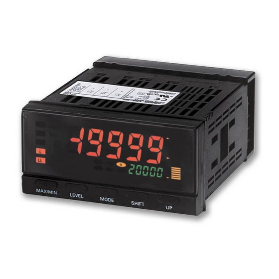
Turns ON when the maximum value or minimum value is displayed in the indicator RUN level. Level/bank display In RUN level, displays the bank if the bank function is ON. (Turns OFF if the bank function is OFF.) In other levels, displays the current level. Status indicators T-ZR: Turns ON when the tare zero function is executed.
-
Page 23: Internal Block Diagram
Section 1 Outline 1.3 Internal Block Diagram Key Display Drive Transistor Input Analog input converter circuit output circuit terminal EEPROM Contact Drive outputs circuit Event Wave- input shaping Event input circuit terminal circuit Linear output Drive Linear output Communications circuit…
-
Page 24: Mounting
Section 2 Preparations 2.1 Mounting ………………2.2 Using I/O………………
-
Page 25
Section 2 Preparations 2.1 Mounting ■ External Dimensions 101.2 Character size for main display (mm) PV display SV display 95 (DeviceNet models: 97) ■ Panel Cutout Dimensions 120 min. +0.8… -
Page 26
Insert watertight packing around the Unit to make the mounting watertight. Watertight packing Insert the adapter into the grooves on the left and right sides of the rear case and push until it reaches the panel and is fixed in place. -
Page 27
Connector: Equivalent to 17JE-13370-02 (manufactured by Honda Tsushin Co., Ltd) (manufactured by DDK) COMMON Stand: 17L-002A (manufactured by DDK) Note: The BCD Output Cable has a D-sub plug. Cover: 17JE-37H-1A (manufactured by DDK); Connector: equivalent to 17JE-23370-02 (D1) (manufactured by DDK) -
Page 28
7: BANK4 10: COM 9: BANK1 Applicable Connector (Sold separately) XG4M-1030 (OMRON) Special Cable (Sold separately) K32-DICN (OMRON) (XG4M-1030 with 3 m cable) Special Cable (for Event Inputs with 8-pin Connector) Model Appearance Wiring K32-DICN Pin No. Signal name S-TMR… -
Page 29
Use an SELV power supply with overcurrent protection for the DC power supply. An SELV power supply has double or reinforced insulation between the input and output, an output voltage of 30 V rms and 42.4 V peak, and is 60 VDC or less. -
Page 30
2.2 Using I/O ● Linear Output Linear currents and voltages are output between terminals B1 to B2 and between B3 to B4. Connect a load within the specified range. Linear output Circuit Diagrams Linear voltage output min. Linear current output… -
Page 31
Section 2 Preparations ● Comparative Outputs Comparative outputs are output to terminals B1 to B3 and C1 to C6. Connect loads within specifications. The electrical life expectancy of the relays is 100,000 operations. Circuit Diagrams Contact Outputs <K34-C1> H and L Output Models <K34-C2>… -
Page 32
2.2 Using I/O Transistor Outputs <K34-T1> NPN Output Models PASS <K34-T2> PNP Output Models PASS… -
Page 33
Section 2 Preparations ● Event Inputs Input control signals. The configuration is shown below. TIMING S-TMR 1: TIMING 2: S-TMR 3: HOLD 4: RESET HOLD 5: ZERO 6: COM 7: BANK4 8: BANK2 RESET 9: BANK1 10: COM ZERO Models with terminal blocks Models with connectors <K35-1><K35-3>… -
Page 34
2.2 Using I/O ● K3HB-X: Input the signal to be measured. The following figure shows the inputs that can be measured by each model. Connect the input devices to the DC Voltage, terminals shown below according to the input type. -
Page 35
Terminal Input impedance Input type Input range measurement range (A+B) DC voltage 199.99 V 199.99 to 219.99 V 10 M min. 19.999 V 19.999 to 21.999 V 1 M min. 1.9999 V 1.9999 to 2.1999 V 1.0000 to 5.0000 V 0.5000 to 5.5000 V… -
Page 36
2.2 Using I/O ● K3HB-V: Input the signal to be measured. The following figure shows the inputs that can be measured by each model. Connect the input devices to the mV, Load Cell Input terminals shown below according to the input type. -
Page 37
Section 2 Preparations ● K3HB-S: Input the signal to be measured. The inputs that can be measured by each model are as follows: Voltage/Current Inputs. Analog Input Connect the input devices to the terminals shown below according to the input type. -
Page 38
2.2 Using I/O ● K3HB-H: Input the signal to be measured. The following figure shows the inputs that can be measured by each model. Connect the input devices to the Temperature Input terminals shown below according to the input type. -
Page 39
Section 2 Preparations 2-16… -
Page 40
Section 3 Basic Application Methods 3.1 Monitoring Tank Levels ………….. 3.2 Monitoring Motor Load Current……….3.3 Weighing Material …………..3.4 Temperature Monitoring/Control with Multi-level Output …. 3-11 3.5 Product Height Measurement and OK/NG Judgement….3-14 3.6 Panel Thickness Inspection ………… -
Page 41: Monitoring Tank Levels
20-section display on the position meter (provides a full-scale level display). • The number of measurements to be averaged (averaging times) can be set to 4 to ensure stable readings of levels in relation to full scale. • Comparative outputs can be generated for tank volume on four levels: dry tank alarm, lower limit alarm, upper limit alarm, and full tank alarm.
-
Page 42
3.1 Monitoring Tank Levels Ultrasonic Displacement Sensor 4 to 20 mA E4PA-LS400-M1 500 to 4,000 mm Process Indicator K3HB-XAD 85%: Full tank Tank level 80%: Upper limit display alarm 4,000 mm 3,500 mm K3HB-XAD input 20%: Lower limit 0 mm alarm 4.00 mA… -
Page 43
HH Control example for the following 3200 Comparative settings: ✽ set value H Full tank alarm set: 3,400 mm Upper limit alarm: 3,200 mm Comparative ✽ Lower limit alarm: 800 mm set value L Dry tank alarm: 400 mm Comparative ✽… -
Page 44
Characters Set value Remarks disp Display value Present value selection pos-t Position Incremental display meter type pos-h 4000 Position meter upper limit Full-scale 0.0 to 4,000 mm pos-l Position meter lower limit ✽ Other parameters are set to their default values. -
Page 45: Monitoring Motor Load Current
• Up to 10 A can be input directly using the K3HB-XAA. • Current can be displayed in amperes (A) up to two digits past the decimal point (@@.@@ A) on the K3HB-XAA. • Two-level output detection can be used for the upper limit.
-
Page 46
3.2 Monitoring Motor Load Current • Comparative set value H is 50.00 A and comparative set value L is 40.00 A. Level output Display High Comparative set value H 50.00 A 40.00 A Comparative set value L Output H Output PASS… -
Page 47
10 s. Input Adjustment Level Parameter Characters Set value Remarks tmg-h nomal Timing hold Normal Display Adjustment Level Parameter Characters Set value Remarks disp Display value Present value selection ✽ Other parameters are set to their default values. -
Page 48: Weighing Material
100 kg, recommended applied voltage of 10 V and rated output of 2 mV/V.) • *Here, 2 mV/V means the load cell outputs 2 mV with 1 V applied at the rated load (100-kg weight in this case). With 10 V applied, the load cell output is 20 mV (= 2 mV x 10).
-
Page 49
Characters Set value Remarks disp Display value Present value selection pos-t Position Incremental display meter type pos-h 1000 Position meter upper limit Full-scale 0.0 to 100.0 kg pos-l Position meter lower limit ✽ Other parameters are set to their default values. 3-10… -
Page 50: Temperature Monitoring/Control With Multi-Level Output
• The furnace temperature can be displayed using the 20-section display on the position meter (provides a full-scale level display). • Comparative output HH turns ON when the furnace is 1,000ºC or higher. Comparative output H turns ON while the furnace is between 800ºC and 1,000ºC.
-
Page 51
Comparative ✽ set value LL ✽ Check on the status displays. Initial Setting Level ( The Setting Level Protect setting must be set to 0 (SET.PT=0) to enable moving to the advanced function setting level. Parameter Characters Set value Remarks… -
Page 52
1400. 0 Position meter upper limit Full-scale 0.0 C to 1400.0 C pos-l Position meter lower limit pvdp Decimal point Display numbers below position the decimal point. ✽ Other parameters are set to their default values. 3-13… -
Page 53: Product Height Measurement And Ok/Ng Judgement
• The forced-zero function can be used for one-touch zero adjustment. • The position meter display can be used to display how far the measurement value deviates from the center. • The dimensions of molded parts can be checked or caps that are not tight on PET bottles can be detected.
-
Page 54
3.5 Product Height Measurement and OK/NG Judgement 2 mm 3 mm Shape of workpiece Insufficient Press-fitting press-fitting omitted Displacement sensor output Near Sync sensor K3HB-S 0. 00 2. 00 -3. 00 Display K3HB-S PASS Comparative outputs ■ K3HB-S Setting Details… -
Page 55
Display Adjustment Level Parameter Characters Set value Remarks pos-t Position Deviation display meter type pos-h 4. 00 Position meter upper limit Full-scale ±4 mm pos-l -4. 00 Position meter lower limit ✽ Other parameters are set to their default values. 3-16… -
Page 56: Panel Thickness Inspection
3.6 Panel Thickness Inspection Advantages of Using the K3HB-S • Calculation mode K-(A+B) can be used to convert panel thickness to actual size and measure it from the outputs of two displacement sensors. • The forced-zero function can be used for one-touch deviation measurement from a reference panel thickness.
-
Page 57
Parameter Characters Set value Remarks ✽ 20. 50 Comparative Monitoring a difference of set value H ±0.5 mm for a reference ✽ 19. 50 Comparative panel thickness of 20 mm set value L ✽ Check on the status displays. 3-18… -
Page 58
Constant K Reference panel thickness 20 mm + sensor displacement 25 mm ,,,. ,, Decimal point position Input Adjustment Level Parameter Characters Set value Remarks tmg-h nomal Timing hold Normal ✽ Other parameters are set to their default values. 3-19… -
Page 59: Measurement Of Disk Eccentricity
• Measurements are taken during the timing input (pushbutton switch in diagram) is ON and the last result is held when it is OFF. • Applications such as measuring shaft eccentricity are possible. (Similar applications are possible for non-metallic objects using an ultrasonic displacement sensor.)
-
Page 60
A2 Displacement (mm) dsp. a2 2. 00 Scaling display value A2 ,,,. ,, Decimal point position Input Adjustment Level Parameter Characters Set value Remarks tmg-h Timing hold Peak-to-peak hold ✽ Other parameters are set to their default values. 3-21… -
Page 61: Step Inspection
Section 3 Basic Application Methods 3.8 Step Inspection Advantages of Using the K3HB-S • Calculation mode A-B can be used to measure steps using two displacement sensors. • The forced-zero function can be used to easily adjust the reference step dimension to the actual object.
-
Page 62
2. 80 3. 20 K3HB-S display K3HB-S PASS comparative outputs * The previous judgement result is held until the Sync Sensor turns ON. (All outputs turn OFF when RESET input is received.) ■ K3HB-S Setting Details RUN Level Parameter Characters Set value Remarks ✽… -
Page 63
20. 000 Scaling input value B2 dsp. b2 2900 Scaling display value B2 ,,,. ,, Decimal point position Input Adjustment Level Parameter Characters Set value Remarks tmg-h Timing hold Sampling hold ✽ Other parameters are set to their default values. 3-24… -
Page 64
Section 4 Initial Setup 4.1 K3HB-X Initial Setup Example (K3HB-XVD)……4.2 K3HB-V Initial Setup Example (K3HB-VLC) ……4.3 K3HB-H Initial Setup Example (K3HB-HTA) ……4.4 K3HB-S Initial Setup Example (K3HB-SSD)…… -
Page 65: K3Hb-X Initial Setup Example (K3Hb-Xvd)
C Set the scaling value. 1. Set scaling input value A1 “inp. a 1” to “1. 0000″ and press the M [MODE] Key. 2. Set scaling display value A1 “dsp. a 1” to “0” and press the M [MODE] Key.
-
Page 66
E Set comparative set value H to 0.700 and set comparative set value L to 0.500. 1. Return to the RUN level by pressing the L [LEVEL] Key for at least 1 s. (Start operation.) 2. Press the M [MODE] Key repeatedly until the SV display status shows 3. -
Page 67: K3Hb-V Initial Setup Example (K3Hb-Vlc)
+10V Load cell * 2 mV/V indicates a load cell output of 2 mV for 1 V applied voltage for the rated load (when using a load of 1 N). When the applied voltage is 10 V, the load cell output is 20 mV (2 mV 10) Initial Setup Flow ●…
-
Page 68
4.2 K3HB-V Initial Setup Example (K3HB-VLC) C Set the scaling value. 1. Set scaling input value A1 “inp. a 1” to “0. 000″ and press the M [MODE] Key. 2. Set scaling display value A1 “dsp. a 1” to “0” and press the M [MODE] Key. -
Page 69: K3Hb-H Initial Setup Example (K3Hb-Hta)
D Set comparative set value H to 500.0 and set comparative set value L to 100.0. 1. Return to the RUN level by pressing the L [LEVEL] Key for at least 1 s. (Start operation.) 2. Press the M [MODE] Key repeatedly until the SV display status shows 3.
-
Page 70
4.3 K3HB-H Initial Setup Example (K3HB-HTA) Clearing Settings If you become confused while setting the parameters and cannot continue, all settings can be cleared so that you can start over. Refer to «5.40 Initializing All Settings» (P.5-100) for information on clearing all settings. -
Page 71: K3Hb-S Initial Setup Example (K3Hb-Ssd)
4 to 20 mA and does not indicate a product failure. B Set the calculation to 0. 1. Move to the initial setting level by pressing the L [LEVEL] Key for at least 3 s with the PV displayed (RUN level).
-
Page 72
F Set comparative set value H to 0.700 and set comparative set value L to 0.500. 1. Return to the RUN level by pressing the L [LEVEL] Key for at least 1 s. (Start operation.) 2. Press the M [MODE] Key repeatedly until the status display shows and then set the value to “0. -
Page 73
Section 4 Initial Setup 4-10… -
Page 74
—— Display Adjustments —————————————————————— 5.25 Setting the Present Measurement Value to “0” …….. 5-65 5.26 Setting the Present Measurement Value to “0” Again when Using a Forced Zero 5-67 5.27 Compensating Forced-zero References ………. 5-70 5.28 Changing Display Refresh Periods ………. -
Page 75: Knowledge Required For Setting Parameters
Section 5 Functions and Operations Knowledge Required for Setting Parameters ■ About Levels Levels are groups of parameters. Levels for the K3HB are classified as follows: Important Depending on the level, measurements may continue Measurement to be executed or stop.
-
Page 76
Knowledge Required for Setting Parameters To change a parameter, move to the level where that parameter is found. The current level is shown on the bank/level display when moving between levels. Level/bank Level display Protect level 0 to 7 Not lit or RUN level (Lights only when banks are used.) -
Page 77
Press the L [LEVEL] and M [MODE] Keys in RUN level for at least 1 s. The PV display will start to flash. Press the same keys for at least 2 s to move to protect level. Press the L [LEVEL] and M [MODE] Keys for at least 1 s to return to RUN level. -
Page 78
The Setting Level Protect setting must be set to 0 (set.pt=0) to enable moving to the advanced function setting level. A Move to the initial setting level, press the M [MODE] Key several times to display the “amov” (move to advanced function setting level) parameter. -
Page 79
D Press the M [MODE] Key to switch to the next parameter. • The changed set value is stored in the internal memory. • If no key is pressed at step C for 5 s,* the set value is registered and the display automatically returns to monitor status. -
Page 80
122. 0 status *1 If no key is pressed for 5 seconds, the set value is registered and the display returns to monitor status. *2 Use the S [SHIFT] and U [UP] Keys to set the set value. Displayed Comparative Set Values… -
Page 81
One of the values between HH and LL will flash, according to the displayed comparative set value. B Press the S [SHIFT] Key to make the 123. 4 SV display flash. — 1 9999 • The setting can be changed when the SV display starts to flash. -
Page 82: Setting Calculations
5.1 Setting Calculations 5.1 Setting Calculations Initial setting level The K3HB-S can add, subtract, and display two analog inputs, input A and input B. Explanation of Functions Calculation and constant K ■ A • Select to use only input A.
-
Page 83
10000 • Select to display the ratio between input A and input B. ■ (B/A-1) 10000 • Select to display the error ratio for input B and input A. Set using the following parameter. Parameter Set value Meaning of set value… -
Page 84: Setting Input Types
0.00 to 199.99 mA d aa 0.000 to 19.999 mA Power supply 50 Hz frequency* 60 Hz * Eliminates inductive noise from the power supply line. Set to the power supply frequency. K3HB-V in-ta Parameter Set value Meaning of set value…
-
Page 85
Input type A in-tb in-tb 1.000 to 5.000 V ±5.000 V (IN-TB) ±10.000 V * Make sure the terminal wiring is correct for the input range. Otherwise, correct values will not be displayed. K3HB-H Meaning of set value in-ta Parameter Set value… -
Page 86
• Set the frequency to 50 Hz or 60 Hz to match the local frequency. If input type A is changed, scaling input values A1 and A2 and scaling display values A1 and A2 are initialized. The same applies to input type B. -
Page 87: Setting Scaling Values
,.,,,, Four digits below the decimal point are displayed. * Use the teaching function to use actual inputs to set scaling input values “inp. a 1,” “inp. a2,” “inp. b1,” and “inp. b2.” Refer to “Teaching” (P.5-17) for details. 5-14…
-
Page 88
Scaling is a function that applies a preset conversion formula to sampled input values to convert each input value to a measurement value. The input values can thus be converted to Units used by the system. The scaling conversion formula for voltage/current input is shown below. -
Page 89
F Repeat steps C to E and set “dsp. a 1,” “inp. a2,” and “dsp. a2.” Use the same procedure to set the “inp. b1,” “dsp. b1,” “inp. b2,” and “dsp. b2” parameters for scaling input B (K3HB-S only). Constant K Use steps G to I to set constant K, if required. -
Page 90
1 s to return to the RUN level. 1234. 5 1 s min. Teaching Use the teaching function to use real inputs to set scaling input values “inp. a 1,” “inp. a2,” “inp.b1,” and “inp.b2.” Parameter Setting Procedure After performing step B, press the U [UP] inp. -
Page 91: Setting The Temperature Unit
Section 5 Functions and Operations 5.4 Setting the Temperature Unit Initial setting level Either ºC or ºF can be set as the temperature unit. Parameter Setting Procedure A Press the L [LEVEL] Key for at least in-ta 3 s in RUN level to move to the initial setting level.
-
Page 92: Setting Measurement Operations
N RESET Sensor error HOLD The PV display will show “——” during RESET input (no measurement status). Remarks Selecting operations for input errors P.5-29 Operation will continue if input error enable is set to OFF (disabled) or OVER (overflow). 5-19…
-
Page 93
The PV display will show “——” in no measurement status. Selecting operations for input errors P.5-29 Remarks Operation will continue if input error enable is set to OFF (disabled) or OVER (overflow). Peak Hold • The maximum value is held while measurement is being… -
Page 94
Input error No measurement Measurement value RESET TIMING The PV display will show “——” in no measurement status. Selecting operations for input errors P.5-29 Remarks Operation will continue if input error enable is set to OFF (disabled) or OVER (overflow). 5-21… -
Page 95
* If the measurement exceeds the measurement range with the “input error enable” parameter (s.err) set to OFF (disabled), then the upper or lower limit of the measurement range will be taken as the measurement value. (The display will flash if the “input error enable” parameter is set to OVER (overflow).) A sensor error will not occur in either case and a comparative value judgment… -
Page 96
5.5 Setting Measurement Operations Parameter Setting Procedure A Press the L [LEVEL] Key for at least 3 s in RUN level to move to the initial setting level. 3 s min. 0.” Displays “ 0” is displayed on the level/bank •… -
Page 97: Shifting The Temperature Input
The shift is linear because there are two separate settings. The shift for the input value set for the “input shift input 1” parameter is set for the “input shift value 1” parameter. The shift for the input value set for the “input shift input 2”…
-
Page 98
5.6 Shifting the Temperature Input Parameter Setting Procedure A Press the L [LEVEL] Key for at least 3 s in RUN level to move to the initial setting level. 3 s min. 0.” Displays “ 0” is displayed on the level/bank •… -
Page 99: Resetting Measurements
Section 5 Functions and Operations 5.7 Resetting Measurements When the RESET input turns ON or the [MAX/MIN] Key is pressed for at least 1 s, the maximum value, minimum value, and outputs are cleared. Measurement is not performed during RESET input. Max. value Min.
-
Page 100: Not Performing Measurements For Set Intervals
With this function measurement is not performed until a set time has s-tmr passed after the S-TMR input turns ON. (Timing starts at the rising edge of the S-TMR input and the PV display is “——” while no measurement has been performed.) (S-TMR) If the power is turned ON while the s-tmr input is ON, measurement will not start until the time set in the s-tmr elapses.
-
Page 101
J Press the L [LEVEL] Key for at least 123. 4 1 s to return to RUN level. 123. 4 1 s min. • S-TMR processing takes priority even if the TIMING input turns ON while the S-TMR input is ON. Remarks Resetting measurements P.5-26… -
Page 102: Selecting Operations For Input Errors
Display Outputs Error display flashes* All outputs are turned OFF. * The errors are “a.err” or “b.err” for the K3HB-S and “s.err” for the K3HB-X/V/H. Parameter Setting Procedure A Press the L [LEVEL] Key for at least 3 s in RUN level to move to the initial setting level.
-
Page 103
SV display flash. s.err • The setting can be changed when the SV display starts to flash. G Use the U [UP] Key to change the SV s. err display to “off.” H Press the M [MODE] Key to switch to cmov the next parameter. -
Page 104: Disabling Cold Junction Compensation
(enabled) compensation 0.0 C (disabled) Parameter Setting Procedure A Press the L [LEVEL] Key for at least 3 s in RUN level to move to the initial setting level. 0.” 3 s min. Displays “ 0” is displayed on the level/bank •…
-
Page 105
F Press the S [SHIFT] Key to make the SV display flash. • The setting can be changed when the SV display starts to flash. G Use the U [UP] Key to change the set value to “off.” H Press the M [MODE] Key to switch to comf the next parameter. -
Page 106: Adjusting Timing Inputs
(0 to 499.9 s*) * The unit for K3HB-X/V/H settings is 100 ms. For example, if 10 is set, then the delay is 10 x 100 ms = 1 s. The on-t (ON timing delay) and off-t (OFF timing delay) settings can be used for the timing hold set values as shown in the following table.
-
Page 107
Explanation of Functions ON timing delay, OFF timing delay The following example shows K3HB-S settings for an ON timing delay of 20 ms and an OFF timing delay of 10 ms. ● Timing Hold Set Value Set to Sampling Hold… -
Page 108
5.11 Adjusting Timing Inputs D Use the U [UP] and S [SHIFT] Keys tmg-h to set the timing hold parameter. E Press the M [MODE] Key several times on-t to switch the PV display to “on-t.” F Press the S [SHIFT] Key to make the on-t SV display flash. -
Page 109: Eliminating Drift Near «0»
Explanation of Functions Zero-limit If the input value is less than the set value, the measurement value becomes “0.” This function is effective to eliminate display drift and displacement near “0.” Set the following parameter for zero-limit. The zero-limit value can be z-lim set only when zero-limit has been enabled.
-
Page 110
SV display flash. • The setting can be changed when the SV display starts to flash. H Use the U [UP] and S [SHIFT] Key to lim-p change the zero-limit value. 0010 I Press the M [MODE] Key to switch to step the next parameter. -
Page 111: Averaging Inputs
(“averaging times”) can also be specified for the input values to be averaged. Simple average is used when the display refresh period is to be lengthened. Moving average is used to remove periodic noise superimposed on input signals. For example, with the K3HB-S, the relationship between the data refresh periods for both simple and moving averages when the averaging times is set to 4 is shown below.
-
Page 112
Averaging times avg-n 1024 1024 * To not use averaging, set the average type “avg-t” to smpl and the averaging times “avg-n” to 1. Parameter Setting Procedure A Press the L [LEVEL] Key for at least 3 s in RUN level to move to the initial setting level. -
Page 113
Section 5 Functions and Operations B Press the L [LEVEL] Key once (less tmg-h than 1 s) to move to the input adjustment nomal level. Less 1.» Displays “ than 1 s 1” is displayed on the level/bank • “… -
Page 114: Detecting Sudden Input Changes
Off-center As shown in the above diagram, when rotating a cylindrical object and measuring the distance from the object using a laser displacement meter, it cannot be judged if the increase in measurement values when the rotating axis is eccentric is due to the eccentricity or to a burr.
-
Page 115
• When the timing hold is set to Normal, the comparison is performed every time. • When the timing hold is set to a setting other than Normal, the comparison is performed on held values. Previous average value comparison is set using the following parameter. -
Page 116
5.14 Detecting Sudden Input Changes D Use the U [UP] and S [SHIFT] Keys to set the init password “-0169.” Press the M [MODE] Key to move to the advanced function setting level. f.” Displays “ f” is displayed on the level/bank display to •… -
Page 117: Changing Comparative Output Patterns
Comparative set value H Comparative set value L Comparative set value LL Output HH Output H Output PASS Output L Output LL * The PASS output turns ON when any of the HH, H, L, or LL output turns OFF. 5-44…
-
Page 118
5.15 Changing Comparative Output Patterns Parameter Setting Procedure A Press the L [LEVEL] Key for at least 3 s in RUN level to move to the initial setting level. 0.” Displays “ 3 s min. 0” is displayed on the level/bank •… -
Page 119: Preventing Output Chattering
Explanation of Functions Hysteresis Hysteresis is a range between the value for which a comparative output turns ON and the value for which the comparative output turns OFF. When the comparative output turns ON, it turns OFF only after the change in measurement values is greater than the set hysteresis.
-
Page 120
0 to 9999 Hysteresis 0 to 9,999 * (HYS) * The decimal point depends on the “decimal point position” setting. Parameter Setting Procedure A Press the L [LEVEL] Key for at least 3 s in RUN level to move to the initial setting level. -
Page 121
Section 5 Functions and Operations H Press the M [MODE] Key to switch to off-d the next parameter. • The set value is registered. I Press the L [LEVEL] Key for at least 1 s to return to the initial setting level. -
Page 122: Outputting For A Set Interval
0 to 1,999 ms (0 to 199.9 s)* shot * The unit for K3HB-X/V/H settings is 100 ms. For example, if 10 is set, then the shot output time is 10 x 100 ms = 1 s. The shot output time is an internal calculation time. The following times are added to the set time to give the actual output time.
-
Page 123
Section 5 Functions and Operations Parameter Setting Procedure A Press the L [LEVEL] Key for at least 3 s in RUN level to move to the initial setting level. 3 s min. 0.” Displays “ 0” is displayed on the level/bank •… -
Page 124
5.17 Outputting for a Set Interval J Press the L [LEVEL] Key for at least 123. 4 1 s to return to RUN level. 123. 4 1 s min. Remarks Delaying output OFF timing P.5-52 5-51… -
Page 125: Delaying Output Off Timing
Explanation of Functions Output OFF delay If the measurement value changes and the comparative result that had been ON until now turns OFF, the comparative output will be held for the time set for the output OFF delay parameter. The comparative output ON time may be too short if measurement values change quickly. When comparative output signals are read by external devices, short signals may not be received properly.
-
Page 126
5.18 Delaying Output OFF Timing D Use the U [UP] and S [SHIFT] Keys init to set the password “-0169.” Press the M [MODE] Key to move to the f.” Displays “ advanced function setting level. f” is displayed on the level/bank •… -
Page 127: Holding Measurement Status
• During HOLD input, signals other than RESET input and bank number selection using bank selection are not accepted. • If the HOLD input turns ON in no measurement status, when a sensor error has occurred, or when there is an overflow, the status at that time is held.
-
Page 128: Holding Comparative Outputs
The comparative output hold function holds the status of all outputs o-stp after any output except for the PASS output turns ON, i.e., it stops refreshing outputs. You can choose to stop outputs and continue measurement, or to stop both.
-
Page 129
F Press the S [SHIFT] Key to make the o-stp SV display flash. • The setting can be changed when the SV display starts to flash. G Use the U [UP] Key to change the set o-stp value. H Press the M [MODE] Key to switch to t-zr the next parameter. -
Page 130: Allocating Another Output To Pass Output
* The output turns ON when an input error occurs. To allocate input errors to the PASS output, set the “input error enable” parameter to s.err. If input error enable is set to off or over, there is no output because there is no input error.
-
Page 131
SV display flash. pass • The setting can be changed when the SV display starts to flash. G Use the U [UP] Key to change the set pass value. H Press the M [MODE] Key to switch to the next parameter. -
Page 132: Reversing Output Logic
Open in out-n alarm The comparative outputs will turn OFF if an input error occurs when “open in alarm” is set. * Turns OFF when an input error occurs. Parameter Setting Procedure A Press the L [LEVEL] Key for at least 3 s in RUN level to move to the initial setting level.
-
Page 133
F Press the S [SHIFT] Key to make the out-n SV display flash. • The setting can be changed when the SV display starts to flash. G Use the U [UP] Key to change the set out-n value. H Press the M [MODE] Key to switch to o-stp the next parameter. -
Page 134: No Output Before Pass Range
Advanced function setting level The standby sequence function can be used to prevent outputs from stdby turning ON for unstable inputs after the power is turned ON. All outputs will remain OFF until the measurement value reaches the PASS value. (STDBY)
-
Page 135
SV display flash. • The setting can be changed when the SV display starts to flash. G Use the U [UP] Key to change the set stdby value to “on.” • Change the set value to “off” to turn OFF the standby sequence. -
Page 136: Performing Linear Output
(e.g., 4 mA for the 4 to 20 mA range) is output. * The value set for the upper limit does not necessarily have to be higher than the value set for the lower limit. The following is an example of reverse scaling.
-
Page 137
Section 5 Functions and Operations * If the upper and lower limit are set to the same value, then the upper limit will equals the lower limit plus 1 for linear output. Parameter Set value Meaning of set value 0-20… -
Page 138: Contents
There are two methods for executing and clearing forced-zero: using key operations and using ZERO inputs. ● Using Key Operations Executing forced-zero: Press the U [UP] Key for less than 1 s while the present value is displayed to execute forced-zero.
-
Page 139
Section 5 Functions and Operations ● Using ZERO Inputs Executing forced-zero: Forced-zero is executed on the rising edge of the ZERO input ON signal (when ZERO input is ON for 1 s max.). Clearing forced-zero: Forced-zero is cleared when ZERO input is ON for 1 s min. -
Page 140: Setting The Present Measurement Value To «0» Again When Using A Forced Zero
The tare zero function shifts the present measurement value to “0” again using a forced zero. Explanation of Functions Tare zero This function is effective when each of two different types of compound are to be weighed, as shown in the following example. Material A…
-
Page 141
Section 5 Functions and Operations ● Using ZERO Inputs Executing tare zero: Tare zero is executed on the rising edge of the ZERO input ON signal during forced- zero execution. Clearing tare zero: If the ZERO input is ON for 1 s, tare zero is cleared. (Forced-zero is cleared if the ZERO input is ON for a further 1 s.) -
Page 142
5.26 Setting the Present Measurement Value to “0” Again when Using a Forced Zero G Use the U [UP] Key to change the set t-zr value to “on.” • Change the set value to “off” to turn OFF tare zero. -
Page 143: Compensating Forced-Zero References
The zero-trimming function compensates the forced-zero shift value based on the measurement value for an OK object (PASS data) while forced-zero is being executed. This function can be used if the timing hold setting is set to sampling hold, peak hold, or bottom hold. Explanation of Functions Zero-trimming The zero-trimming algorithm is shown below.
-
Page 144
5.27 Compensating Forced-zero References Parameter Setting Procedure A Press the L [LEVEL] Key for at least 3 s in RUN level to move to the initial setting level. 3 s min. 0.” Displays “ 0” is displayed on the level/bank •… -
Page 145
Section 5 Functions and Operations J Press the L [LEVEL] Key for at least 123. 4 1 s to return to RUN level. 123. 4 1 s min. Remarks Setting the present measurement value to “0” (forced-zero) P.5-65 5-72… -
Page 146: Changing Display Refresh Periods
When measurement values change rapidly and the display changes with d. ref the measurement values, flickering often occurs and the display becomes difficult to read. The flickering can be suppressed and the display made easier to read in such situations by delaying the display refresh period. (D.REF) The display refresh period is set using the following parameter.
-
Page 147
Section 5 Functions and Operations G Press the L [LEVEL] Key for at least 123. 4 1 s to return to RUN level. 123. 4 1 s min. Remarks Averaging inputs P.5-38 Detecting sudden input changes P.5-41 5-74… -
Page 148: Holding Maximum And Minimum Values
90000 90000 * If input error enable (s.err) is ON and a sensor error occurs, the input error will be displayed on the maximum and minimum display. The input error is cleared by a RESET input or by pressing the [MAX/MIN] Key for at least 1 s.
-
Page 149
Reset Held Power supply * Holds values even for no measurement status, an input error, or an overflow. * Holds values even with a software reset performed through key operations or communications. * The power interruption memory cannot be accessed if the startup compensation timer is enabled when the power is turned ON. -
Page 150
5.29 Holding Maximum and Minimum Values Changing normal display values to maximum and minimum values Remarks P.5-78 5-77… -
Page 151: Changing Normal Display Values To Maximum And Minimum Values
5.30 Changing Normal Display Values to Maximum and Minimum Values Display adjustment level The PV display value displayed after power is turned ON, after the disp RESET input, immediately after moving to RUN level, and immediately after automatic display return to RUN or adjustment levels can be set to either the present value, maximum value, or minimum value.
-
Page 152
5.30 Changing Normal Display Values to Maximum and Minimum Values Displaying/not displaying comparative set values P.5-82 Remarks Using position meters P.5-85 Changing automatic display return time P.5-73 5-79… -
Page 153: Setting The Step For Changing The Rightmost Digit
Section 5 Functions and Operations 5.31 Setting the Step for Changing the Rightmost Digit Input adjustment level The step for changing the rightmost digit on the display is set using the step following parameter. Parameter Set value Meaning of set value…
-
Page 154
5.31 Setting the Step for Changing the Rightmost Digit G Press the L [LEVEL] Key for at least 123. 4 1 s to return to RUN level. 123. 4 1 s min. 5-81… -
Page 155: Displaying/Not Displaying Comparative Set Values
If “comparative set value display” is set to OFF, the comparative set value display will turn OFF (not be lit) after 10 s in RUN level. The comparative set value is displayed again when any key is pressed. Parameter Setting Procedure…
-
Page 156: Changing Display Colors
Display adjustment level The PV display color can be switched when the comparative result color changes from PASS to HH, H, L, or LL, or when an input error occurs during operation in RUN, adjustment, or protect levels. (COLOR) This function is called “display color selection.” The color switching pattern is set using the following parameter.
-
Page 157
Section 5 Functions and Operations E Use the U [UP] Key to change the set color value. red-g F Press the M [MODE] Key to switch to disp the next parameter. • The set value is registered. G Press the L [LEVEL] Key for at least 123. -
Page 158: Using The Position Meter
5.34 Using the Position Meter 5.34 Using the Position Meter Display adjustment level The meter on the right side of the front panel with 20 sections is called pos-t the “position meter” and shows the position of the displayed value (present value, maximum, or minimum) in relation to any values set using the position meter upper and lower limits.
-
Page 159
Section 5 Functions and Operations Parameter Setting Procedure A Press the L [LEVEL] Key for at least 3 s in RUN level to move to the initial setting level. 0.” 3 s min. Displays “ 0” is displayed on the level/bank •… -
Page 160
5.34 Using the Position Meter J Press the S [SHIFT] Key to make the pos-l SV display flash. — 1 9999 • The setting can be changed when the SV display starts to flash. K Use the U [UP] and S [SHIFT] Keys… -
Page 161: Automatic Return To Normal Display
5.35 Automatic Return to Normal Display Display adjustment level If no keys are operated for a specified time after switching the display in the RUN level or adjustment level, the display will automatically return to the RUN level. The time until the display returns automatically…
-
Page 162
5.35 Automatic Return to Normal Display G Press the L [LEVEL] Key for at least 123. 4 1 s to return to RUN level. 123. 4 1 s min. 5-89… -
Page 163: No Decimal Point Display
(PVDP) If no display is selected, then numbers past the decimal point are rounded off to display the nearest integer. Comparative judgments, however, will use the decimal point. Parameter…
-
Page 164
5.36 No Decimal Point Display G Press the L [LEVEL] Key for at least 123. 4 1 s to return to RUN level. 123. 4 1 s min. 5-91… -
Page 165: Performing Output Tests
Section 5 Functions and Operations 5.37 Performing Output Tests Output test level The output test function is used to set test measurement values using test the keys to check the comparative outputs against the set comparative set values. (TEST) A test measurement value is set using the following parameter.
-
Page 166: Using Comparative Set Value Banks
8 banks, numbered 0 to 7. Banks can be selected using front panel keys or an event input. * If the bank copy function is used, the comparative set values set to one bank can be copied to all banks.
-
Page 167
Section 5 Functions and Operations Parameter Setting Procedure A Press the L [LEVEL] Key for at least 3 s in RUN level to move to the initial setting level. 3 s min. 0.” Displays “ 0” is displayed on the level/bank •… -
Page 168
. l sv .ll 99999 0 to 7 (SV .L) The decimal point depends on the “decimal point position” parameter setting. sv . ll Parameter Setting Procedure A Press the L [LEVEL] Key for at least (SV .LL) 3 s in RUN level to move to the initial 0 to 7 setting level. -
Page 169
PV display to “copy.” K Press the S [SHIFT] Key to make the copy SV display flash. L Use the U [UP] Key to change the set copy value. M Press the M [MODE] Key to switch to sv. -
Page 170
Proceed to step D to correct Proceed to step if bank copied bank parameters. comparative set value settings have been completed. N Press the L [LEVEL] Key for at least 123. 4 1 s to return to RUN level. 123. 4 1 s min. Remarks Copying bank comparative set values P.5-98… -
Page 171: Copying Bank Comparative Set Values
Section 5 Functions and Operations 5.39 Copying Bank Comparative Set Values The bank copy function is used to specify a bank between 0 and 7 and copy copy the group of comparative set values in that bank to all banks.
-
Page 172
5.39 Copying Bank Comparative Set Values I Press the M [MODE] Key to switch to sv. bnk the next parameter. • The comparative set value from the copy source bank selected in step D will be copied to all banks. -
Page 173: Initializing All Settings
“on.” * If this operation is performed, all parameters return to the initial settings and current settings are lost. It is recommended that before performing this operation, the Parameter List at the end of this manual or some other method is used to record the current set values.
-
Page 174
5.40 Initializing All Settings G Press the M [MODE] Key to switch to the pass next parameter and execute initialization. pass • The set value is registered. H Press the L [LEVEL] Key for at least 1 s to return to the initial setting level. -
Page 175: Limiting Key Operations
The key protect function limits level and parameter changes using key run. pt operations. There are five kinds of key protection. The parameters, settings and details on the limitations of each kind of protection are outlined below. (RUN.PT) : Enabled, : Prohibited set.
-
Page 176
C Press the S [SHIFT] Key to make the wt. pt SV display flash. D Use the U [UP] Key to change the SV wt. pt display. E Press the M [MODE] Key to switch to zr. pt the next parameter. -
Page 177
Section 5 Functions and Operations F Press the L [LEVEL] and M [MODE] 123. 4 Keys together for at least 1 s to return 123. 4 to RUN level. 1 s min. 5-104… -
Page 178: About User Calibration
Section 6 User Calibration 6.1 About User Calibration…………… 6.2 User Calibration Operation …………
-
Page 179
6.1 About User Calibration The K3HB is calibrated correctly at shipment, so there is normally no need for the user to calibrate it. The K3HB does has a function to calibrate analog inputs that can be used when required. Each time data is calibrated, earlier calibration data is overwritten. Be careful, therefore, because default data is lost when the K3HB is calibrated by the user. -
Page 180
User calibration is performed for input A if “A” is included in the calculation and input B if “B” is included in the calculation. Calibration is performed on both inputs A and B if both “A” and “B” are included in the calculation. -
Page 181
The display cannot handle bias compensation values because they are temperature readings rather than a count. This means the value that is read during calibration is not a bias value, but the calibration value for the main input. -
Page 182
• Thermocouples are calibrated by type, i.e., Group 1 (input types 2, 4, 7, 8, 10, and 14) and Group 2 (input types 3, 5, 6, 9, 11, 12, and 13). -
Page 183
• The parameter can be changed when the SV display starts to flash. C Use the U [UP] and S [SHIFT] Keys to set the password. The password is “1201”(1201). D Press the M [MODE] Key to write the password. -
Page 184
Refer to the table on P.6-9 for details on the relationship between parameters and the input type. • The display will be as shown if “A” is baa20 not included in the calculation, and 7f00 the calibration then will be for input “B”… -
Page 185
Section 6 User Calibration I Use the U [UP] Key to change the set value to “yes.” J Press the M [MODE] Key. • The calibration value is “registered.” • When there are two inputs, input B is calibrated next. -
Page 186
6.2 User Calibration Operation M After the count stabilizes, press the U [UP] Key. • The current value is displayed. N Press the U [UP] Key again. • The count value is set. ● Input Type and Parameter/Reference Signal K3HB-X… -
Page 187
Section 6 User Calibration K3HB-V Calibration upper limit Calibration lower limit Input type Reference Reference Parameters Parameters signal signal 199. 99 0. 00 0.00 to 199.99 mV 0.00 mV 199.99 mV 19. 999 0. 000 0.000 to 19.999 mV 0.000 mV 19.999 mV… -
Page 188: Section 7 Troubleshooting
Section 7 Troubleshooting 7.1 Error Displays …………….7.2 Countermeasures …………..
-
Page 189: 7.1 Error Displays
If the problem still persists after performing initialization, repair is necessary. *2. K3HB-S only. When an error occurs for input A or inputs A and B, the display will show “a. err.” When an error occurs for input B only, the display will show “b. err.”…
-
Page 190: 7.2 Countermeasures
Is the “startup compensation The “startup compensation after the power is turned ON. timer” setting too long? timer” can be set up to 99.9 s. Change the setting to an appropriate value. Is the HOLD input still ON? Turn OFF the HOLD input.
-
Page 191
Section 7 Troubleshooting… -
Page 192: Appendices
Appendices Specifications………………Model Number Structure…………..Parameter List………………A-12 Parameter Display Conditions …………A-17 About Parameters …………….A-18 Sampling and Comparative Output Response Times……A-26 No Measurement Status …………..A-30…
-
Page 193: Specifications
10 VDC ± 10% 100 mA (only for models with external power supply) Input range K3HB-S DC voltage/current (0 to 20 mA, 4 to 20 mA, 0 to 5 V, 1 to 5 V, ±5 V, (measure- ±10 V) 2 channels…
-
Page 194
For ±19.999 mA or 4 to 20 mA: max., For ±1.9999 mA: 33 max. AC voltage: 1 M min., AC current for 0 to 10 A or 0 to 1.9999 A: 0.5 VACT, For 0 to 199.99 mA: 1 max., For 0 to 19.999 mA: 10 max. -
Page 195
2,300 VAC for 1 min between external terminals and case Noise immunity 100 to 240-VAC models: ±1,500 V at power supply terminals in normal or common mode (waveform with 1-ns rising edge and pulse width of 1 s/100 ns) 24-VAC/VDC models: ±1,500 V at power supply terminals in normal or common… -
Page 196
EN61010-1 (IEC61010-1): Pollution degree 2/overvoltage category II EN61326: 1997, A1: 1998, A2: 2001 * Applies only when the product is used indoors. The K3HB-XVA@@ complies with UL standards when the applied input voltage is within the range 0 to 150 VAC. (EMI) -
Page 197
0.000 to 21.999 mA Note: The accuracy is for an input frequency range of 40 Hz to 1 kHz (except for AD current input A and B ranges) and an ambient temperature of 23 ±5 C. The error, however, increases below 10% of the maximum input value. -
Page 198
0.5 to 5.5 V 5 to 5 V 5.5 to 5.5 V For 1 input: ±0.1% FS ± 1 digit max. (for 23±5 C) 10 to 10 V 11 to 11 V For 2 inputs: ±0.2% FS ± 1 digit max. (for 23±5 C) -
Page 199
2. Do not use the Sensor outside of the derating area (i.e., do not use it in the area labeled (1) in the above graphics). Doing so may deteriorate or damage internal components. -
Page 200: Model Number Structure
Voltage and Current Process Indicator Weighing Indicator Linear Sensor Indicator Temperature Indicator 2. Input Range Code Auxiliary output and external power supply specifications DC voltage input DC current input AC voltage input AC current input Load cell input (DC low-voltage input)
-
Page 201
Linear current output (DC0(4) — 20 mA) + Sensor power supply (10 VDC, ±5%, 100 mA) Linear voltage output (DC0(1) — 5 V, 0 to 10 V) + Sensor power supply (12 VDC, ±10%, 80 mA) Linear voltage output (DC0(1) — 5 V, 0 to 10 V) + Sensor power supply (10 VDC, ±5%, 100 mA) Sensor power supply, 12 VDC, ±10%, 80 mA… -
Page 202
K3HB-HTA K34-BCD K33-L2A K3HB-SSD K34-DRT K33-L1B K35-1 100-240VAC K33-L2B K35-2 K33-A K35-3 K3HB-XVD • CPA and CPB can be K33-B K35-4 K3HB-XAD combined with relay outputs K33-FLK1A K3HB-XVA only. K33-FLK3A K3HB-XAA • Only one of communications, 24 VAC/VDC K33-FLK1B K3HB-VLC… -
Page 203: Parameter List
Appendices Parameter List Enter the set value before using. Level Parameter name Characters Setting range Characters Initial value Decimal point Unit value Version Status Measurement value 19999 to 99999 Max. value 19999 to 99999 Min. value 19999 to 99999 RUN/adjustment run.pt…
-
Page 204
0-20, 4-20, 0-5, 4-20 Input type B 0 to 20 mA, 4 to 20 mA, 1-5, 5, 10 0 to 5 V, 1 to 5 V, ±5 V, ±10 V Scaling input value B1 inp.b1 -19999 to 99999 4000 -19999 to 99999 Conforms to input type. -
Page 205
Comparative set value off, on display Display refresh period d.ref off, 0.5 s, 1 s, 2 s, 4 s off, 0. 5, 1, 2, 4 Display color selection color grn-r, grn, red-g, grn-r Green (red), green, red (green), red… -
Page 206
Level Parameter name Characters Setting range Characters Initial value Decimal point Unit value s?.bnk 0 to 7 Comparative set value 0 to 7 bank s?0.hh -19999 to 99999 99999 Comparative set value 19999 to 99999 Conforms to decimal point position. -
Page 207
H Linear output calibration value L *1 Variable C0 is sued for reading communications data. *2 Set the “bank” parameter to “EV” when an event input (connector) is mounted as a standard feature or has been added. A-16… -
Page 208: Parameter Display Conditions
Cold junction compensation Move to the calibration level <K35-1 to 4> Event Input Items marked may not be displayed due to Unit configuration or settings. Others are always displayed. <K34-C1> Relay Output (H/L) Displayed if the Unit is connected. <K34-C2>…
-
Page 209: About Parameters
1 s min. 0169 1 s max. Press the @ [LEVEL] key for at least 1 s from any display (except for the protect level) to return to the first parameter in the RUN or initial setting level. Advanced function setting level…
-
Page 210
Keys to change the 12345 12345 settings. The setting to be 4000 04000 changed will flash. *If a key is not pressed within 5 s, the present setting will be saved and the display will return to monitor mode. To next parameter. A-19… -
Page 211
0169 1 s min. 1 s max. Press the @ [LEVEL] key for at least 1 s from any display (except for the protect level) to return to the first parameter in the RUN or initial setting level. Advanced function setting level… -
Page 212
Keys to change the 12345 12345 settings. The setting to be 4000 04000 changed will flash. *If a key is not pressed within 5 s, the present setting will be saved and the display will return to monitor mode. To next parameter. A-21… -
Page 213
Change the setting level protection to «0». -19,999 to 99,999 Press the @ [LEVEL] key for at least 1 s from any display (except for the protect level) to return to the first Password: parameter in the RUN or initial setting level. -
Page 214
Keys to change the 12345 12345 settings. The setting to be 4000 04000 changed will flash. *If a key is not pressed within 5 s, the present setting will be saved and the display will return to monitor mode. To next parameter. A-23… -
Page 215
0169 L E V E L L E V E L Press the @ [LEVEL] key for at least 1 s from any display (except 1 s max. 1 s min. for the protect level) to return to the first parameter in the RUN or initial setting level. -
Page 216
Keys to change the 12345 12345 settings. The setting to be 4000 04000 changed will flash. *If a key is not pressed within 5 s, the present setting will be saved and the display will return to monitor mode. To next parameter. A-25… -
Page 217: Sampling And Comparative Output Response Times
Appendices Sampling and Comparative Output Response Times The K3HB-S sampling and comparative output response times depend on the calculations, timing hold type, and, for simple averaging, the averaging times. Refer to the following description for details. ■ Output Refresh Period The K3HB-S repeats input reads, calculation, and judgement output processing.
-
Page 218
Averaging times (n) Once * The output every 0.5 ms is the comparative output corresponding to the input change for either input A or input B. The input change for both inputs is reflected in the comparative outputs every 1 ms. A-27… -
Page 219
If the number of averaging times is 8, the comparative output that corresponds averaging to the average for 8 read inputs (4 input A’s and 4 input B’s) is output. 4 ms + output response time (See note 1.) Comparative output response time = 0.5 ms M (averaging times) + output response time (See note 1.) -
Page 220
Sampling and Comparative Output Response Times ■ Relationship between Timing Signals and Reset or Hold Signals The following tables show whether or not measurement is performed for each signals timing input, when timing hold is not set to normal. ● Timing Signal and Reset Signal… -
Page 221: No Measurement Status
RESET input, or startup compensation timer operation. • When the [MAX/MIN] Key is pressed for at least 1 s. * If the hold signal turns ON when no measurement has been made, the no measurement status is held. A-30…
-
Page 222
Index INDEX Display color selection 5-83 Display refresh period 5-73 Adjustment Display value selection 5-78 Advanced function settings Display, returning to RUN level 5-88 Analog input 2-11 2-13 2-14 2-15 Display, rightmost digit step 5-80 Automatic display return 5-88 Drawout… -
Page 223
Maximum and minimum values, holding 5-75 Measurement operations 5-19 Measurement status, holding 5-54 Measurement value, setting to 0 Panel cutout dimensions 5-65 Measurement value, setting to 0 again Parameter display conditions 5-67 A-12 Measurements, delaying Parameter list 5-27 A-12 Measurements, resetting… -
Page 224
Simple average 5-38 Standard output 5-44 Standby sequence Startup compensation timer 5-27 Status indicators Step value 5-80 SV display SV display status indicators Tare zero 5-67 Teaching 5-17 Temperature input, shifting 5-24 Temperature unit 5-18 Timing delay Timing hold 3-10… -
Page 225
Index INDEX-4… -
Page 226
Regional Headquarters OMRON EUROPE B.V. Wegalaan 67-69, NL-2132 JD Hoofddorp The Netherlands Tel: (31)2356-81-300/Fax: (31)2356-81-388 OMRON ELECTRONICS LLC 1 East Commerce Drive, Schaumburg, IL 60173 U.S.A. Tel: (1)847-843-7900/Fax: (1)847-843-8568 OMRON ASIA PACIFIC PTE. LTD. 83 Clemenceau Avenue, #11-01, UE Square,…
Hide thumbs
Also See for K3HB-H:
- Manual (33 pages)
-
Contents
-
Table of Contents
-
Troubleshooting
-
Bookmarks
Quick Links
Cat. No. N128-E1-01D
K3HB-S/-X/-V/-H
Digital Indicators
USER’S MANUAL
Related Manuals for Omron K3HB-H
Summary of Contents for Omron K3HB-H
-
Page 1
Cat. No. N128-E1-01D K3HB-S/-X/-V/-H Digital Indicators USER’S MANUAL… -
Page 2
Notice (1) All rights reserved. No part of this manual may be reprinted or copied without the prior written permission of OMRON. (2) The specifications and other information contained in this manual are subject to change without notice in order to make improvements. -
Page 3
The following are some examples of applications for which particular attention must be given. This is not intended to be an exhaustive list of all possible uses of the products, nor is it intended to imply that the uses listed may be suitable for the products. -
Page 4
PERFORMANCE DATA Performance data given in this manual is provided as a guide for the user in determining suitability and does not constitute a warranty. It may represent the result of OMRON’s test conditions, and the users must correlate it to actual application requirements. -
Page 5
Safety Precautions ● Definition of Precautionary Information The following notation is used in this manual to provide precautions required to ensure safe usage of the product. The safety precautions that are provided are extremely important to safety. Always read and heed the information provided in all safety precautions. -
Page 6
Do not use the equipment for measurements within Measurement Categories III and IV for K3HB-X and II, III, and IV for K3HB-S, K3HB-V, and K3HB-H (according to IEC61010-1). Doing so may occasionally cause unexpected operation, resulting in minor or moderate injury, or damage to the equipment. -
Page 7
CAUTION Make sure that the product will not be adversely affected if the DeviceNet cycle time is lengthened as a result of changing the program with online editing. Extending the cycle time may cause unexpected operation, occasionally resulting in minor or moderate injury, or damage to the equipment. -
Page 8
(10) Ensure that the rated voltage is achieved no longer than 2 s after turning the power ON. (11) Allow the product to operate without load for at least 15 minutes after the power is turned ON. -
Page 9
(16) Do not connect anything to unused terminals. (17) Output turns OFF when the mode is changed or settings are initialized. Take this into consideration when setting up the control system. (18) Install an external switch or circuit breaker that complies with applicable IEC60947-1 and IEC60947-3 requirements and label them clearly so that the operator can quickly turn OFF the power. -
Page 10
Signal input 2 conductors with shield (3) If a noise filter is used for the power supply, check the voltage and current, and install the noise filter as close to the product as possible. (4) Reception interference may occur if the product is used close to a radio, television, or… -
Page 11
● Revision History The revision code of this manual is given at the end of the catalog number at the bottom left of the back cover. Cat. No. N128-E1-01D Revision code Date Pages and changes November 2003 Original production January 2004 Page 2-4: Bottom left portion of C corrected. -
Page 12
Describes the mounting and wiring required before using the product. Section 3 Basic Application Methods Shows typical applications for the product. Also shows wiring and parameter settings which enables the user to understand how to use the product from practical examples. Section 4 Initial Setup Describes the initial setup process when using this product. -
Page 13
● Settings Data Notation The letters of the alphabet in settings data are displayed as shown below. ● Applicable Model Notation The following symbols are used to indicate the applicable models for specific functions. K3HB-X@@ K3HB-V@@ K3HB-H@@ K3HB-S@@… -
Page 14: Table Of Contents
K3HB-H Initial Setup Example (K3HB-HTA)……..K3HB-S Initial Setup Example (K3HB-SSD) ……..
-
Page 15
5.31 Setting the Step for Changing the Rightmost Digit ……. -
Page 16
Sampling and Comparative Output Response Times …….. -
Page 17
Contents CONTENTS-4… -
Page 18
Section 1 Outline 1.1 Main Functions and Features of the K3HB …….. 1.2 Component Names and Functions ……….1.3 Internal Block Diagram ………….. -
Page 19: Main Functions And Features Of The K3Hb
Section 1 Outline 1.1 Main Functions and Features of the K3HB Measurement Input calculation Timing hold Timing delay Two measurement values can Using external timing signal The start and stop timing for be added, subtracted, or the inputs, synchronous measurements can be ratio calculated.
-
Page 20
1.1 Main Functions and Features of the K3HB Key operations Teaching Key protection During scaling, the input value Limits key-operated level and during measurement can be parameter changes to prevent set, as is, as the scaling input inadvertent key operations and value. -
Page 21
The current display value can The PV display color can be When inputs change quickly, be selected from the present set to either green or red. The the display refresh period can value, the maximum value, present value color can be be delayed to reduce and the minimum value. -
Page 22: Component Names And Functions
Turns ON when the maximum value or minimum value is displayed in the indicator RUN level. Level/bank display In RUN level, displays the bank if the bank function is ON. (Turns OFF if the bank function is OFF.) In other levels, displays the current level. Status indicators T-ZR: Turns ON when the tare zero function is executed.
-
Page 23: Internal Block Diagram
Section 1 Outline 1.3 Internal Block Diagram Key Display Drive Transistor Input Analog input converter circuit output circuit terminal EEPROM Contact Drive outputs circuit Event Wave- input shaping Event input circuit terminal circuit Linear output Drive Linear output Communications circuit…
-
Page 24: Mounting
Section 2 Preparations 2.1 Mounting ………………2.2 Using I/O………………
-
Page 25
Section 2 Preparations 2.1 Mounting ■ External Dimensions 101.2 Character size for main display (mm) PV display SV display 95 (DeviceNet models: 97) ■ Panel Cutout Dimensions 120 min. +0.8… -
Page 26
Insert watertight packing around the Unit to make the mounting watertight. Watertight packing Insert the adapter into the grooves on the left and right sides of the rear case and push until it reaches the panel and is fixed in place. -
Page 27
Connector: Equivalent to 17JE-13370-02 (manufactured by Honda Tsushin Co., Ltd) (manufactured by DDK) COMMON Stand: 17L-002A (manufactured by DDK) Note: The BCD Output Cable has a D-sub plug. Cover: 17JE-37H-1A (manufactured by DDK); Connector: equivalent to 17JE-23370-02 (D1) (manufactured by DDK) -
Page 28
7: BANK4 10: COM 9: BANK1 Applicable Connector (Sold separately) XG4M-1030 (OMRON) Special Cable (Sold separately) K32-DICN (OMRON) (XG4M-1030 with 3 m cable) Special Cable (for Event Inputs with 8-pin Connector) Model Appearance Wiring K32-DICN Pin No. Signal name S-TMR… -
Page 29
Use an SELV power supply with overcurrent protection for the DC power supply. An SELV power supply has double or reinforced insulation between the input and output, an output voltage of 30 V rms and 42.4 V peak, and is 60 VDC or less. -
Page 30
2.2 Using I/O ● Linear Output Linear currents and voltages are output between terminals B1 to B2 and between B3 to B4. Connect a load within the specified range. Linear output Circuit Diagrams Linear voltage output min. Linear current output… -
Page 31
Section 2 Preparations ● Comparative Outputs Comparative outputs are output to terminals B1 to B3 and C1 to C6. Connect loads within specifications. The electrical life expectancy of the relays is 100,000 operations. Circuit Diagrams Contact Outputs <K34-C1> H and L Output Models <K34-C2>… -
Page 32
2.2 Using I/O Transistor Outputs <K34-T1> NPN Output Models PASS <K34-T2> PNP Output Models PASS… -
Page 33
Section 2 Preparations ● Event Inputs Input control signals. The configuration is shown below. TIMING S-TMR 1: TIMING 2: S-TMR 3: HOLD 4: RESET HOLD 5: ZERO 6: COM 7: BANK4 8: BANK2 RESET 9: BANK1 10: COM ZERO Models with terminal blocks Models with connectors <K35-1><K35-3>… -
Page 34
2.2 Using I/O ● K3HB-X: Input the signal to be measured. The following figure shows the inputs that can be measured by each model. Connect the input devices to the DC Voltage, terminals shown below according to the input type. -
Page 35
Terminal Input impedance Input type Input range measurement range (A+B) DC voltage 199.99 V 199.99 to 219.99 V 10 M min. 19.999 V 19.999 to 21.999 V 1 M min. 1.9999 V 1.9999 to 2.1999 V 1.0000 to 5.0000 V 0.5000 to 5.5000 V… -
Page 36
2.2 Using I/O ● K3HB-V: Input the signal to be measured. The following figure shows the inputs that can be measured by each model. Connect the input devices to the mV, Load Cell Input terminals shown below according to the input type. -
Page 37
Section 2 Preparations ● K3HB-S: Input the signal to be measured. The inputs that can be measured by each model are as follows: Voltage/Current Inputs. Analog Input Connect the input devices to the terminals shown below according to the input type. -
Page 38
2.2 Using I/O ● K3HB-H: Input the signal to be measured. The following figure shows the inputs that can be measured by each model. Connect the input devices to the Temperature Input terminals shown below according to the input type. -
Page 39
Section 2 Preparations 2-16… -
Page 40
Section 3 Basic Application Methods 3.1 Monitoring Tank Levels ………….. 3.2 Monitoring Motor Load Current……….3.3 Weighing Material …………..3.4 Temperature Monitoring/Control with Multi-level Output …. 3-11 3.5 Product Height Measurement and OK/NG Judgement….3-14 3.6 Panel Thickness Inspection ………… -
Page 41: Monitoring Tank Levels
20-section display on the position meter (provides a full-scale level display). • The number of measurements to be averaged (averaging times) can be set to 4 to ensure stable readings of levels in relation to full scale. • Comparative outputs can be generated for tank volume on four levels: dry tank alarm, lower limit alarm, upper limit alarm, and full tank alarm.
-
Page 42
3.1 Monitoring Tank Levels Ultrasonic Displacement Sensor 4 to 20 mA E4PA-LS400-M1 500 to 4,000 mm Process Indicator K3HB-XAD 85%: Full tank Tank level 80%: Upper limit display alarm 4,000 mm 3,500 mm K3HB-XAD input 20%: Lower limit 0 mm alarm 4.00 mA… -
Page 43
HH Control example for the following 3200 Comparative settings: ✽ set value H Full tank alarm set: 3,400 mm Upper limit alarm: 3,200 mm Comparative ✽ Lower limit alarm: 800 mm set value L Dry tank alarm: 400 mm Comparative ✽… -
Page 44
Characters Set value Remarks disp Display value Present value selection pos-t Position Incremental display meter type pos-h 4000 Position meter upper limit Full-scale 0.0 to 4,000 mm pos-l Position meter lower limit ✽ Other parameters are set to their default values. -
Page 45: Monitoring Motor Load Current
• Up to 10 A can be input directly using the K3HB-XAA. • Current can be displayed in amperes (A) up to two digits past the decimal point (@@.@@ A) on the K3HB-XAA. • Two-level output detection can be used for the upper limit.
-
Page 46
3.2 Monitoring Motor Load Current • Comparative set value H is 50.00 A and comparative set value L is 40.00 A. Level output Display High Comparative set value H 50.00 A 40.00 A Comparative set value L Output H Output PASS… -
Page 47
10 s. Input Adjustment Level Parameter Characters Set value Remarks tmg-h nomal Timing hold Normal Display Adjustment Level Parameter Characters Set value Remarks disp Display value Present value selection ✽ Other parameters are set to their default values. -
Page 48: Weighing Material
100 kg, recommended applied voltage of 10 V and rated output of 2 mV/V.) • *Here, 2 mV/V means the load cell outputs 2 mV with 1 V applied at the rated load (100-kg weight in this case). With 10 V applied, the load cell output is 20 mV (= 2 mV x 10).
-
Page 49
Characters Set value Remarks disp Display value Present value selection pos-t Position Incremental display meter type pos-h 1000 Position meter upper limit Full-scale 0.0 to 100.0 kg pos-l Position meter lower limit ✽ Other parameters are set to their default values. 3-10… -
Page 50: Temperature Monitoring/Control With Multi-Level Output
• The furnace temperature can be displayed using the 20-section display on the position meter (provides a full-scale level display). • Comparative output HH turns ON when the furnace is 1,000ºC or higher. Comparative output H turns ON while the furnace is between 800ºC and 1,000ºC.
-
Page 51
Comparative ✽ set value LL ✽ Check on the status displays. Initial Setting Level ( The Setting Level Protect setting must be set to 0 (SET.PT=0) to enable moving to the advanced function setting level. Parameter Characters Set value Remarks… -
Page 52
1400. 0 Position meter upper limit Full-scale 0.0 C to 1400.0 C pos-l Position meter lower limit pvdp Decimal point Display numbers below position the decimal point. ✽ Other parameters are set to their default values. 3-13… -
Page 53: Product Height Measurement And Ok/Ng Judgement
• The forced-zero function can be used for one-touch zero adjustment. • The position meter display can be used to display how far the measurement value deviates from the center. • The dimensions of molded parts can be checked or caps that are not tight on PET bottles can be detected.
-
Page 54
3.5 Product Height Measurement and OK/NG Judgement 2 mm 3 mm Shape of workpiece Insufficient Press-fitting press-fitting omitted Displacement sensor output Near Sync sensor K3HB-S 0. 00 2. 00 -3. 00 Display K3HB-S PASS Comparative outputs ■ K3HB-S Setting Details… -
Page 55
Display Adjustment Level Parameter Characters Set value Remarks pos-t Position Deviation display meter type pos-h 4. 00 Position meter upper limit Full-scale ±4 mm pos-l -4. 00 Position meter lower limit ✽ Other parameters are set to their default values. 3-16… -
Page 56: Panel Thickness Inspection
3.6 Panel Thickness Inspection Advantages of Using the K3HB-S • Calculation mode K-(A+B) can be used to convert panel thickness to actual size and measure it from the outputs of two displacement sensors. • The forced-zero function can be used for one-touch deviation measurement from a reference panel thickness.
-
Page 57
Parameter Characters Set value Remarks ✽ 20. 50 Comparative Monitoring a difference of set value H ±0.5 mm for a reference ✽ 19. 50 Comparative panel thickness of 20 mm set value L ✽ Check on the status displays. 3-18… -
Page 58
Constant K Reference panel thickness 20 mm + sensor displacement 25 mm ,,,. ,, Decimal point position Input Adjustment Level Parameter Characters Set value Remarks tmg-h nomal Timing hold Normal ✽ Other parameters are set to their default values. 3-19… -
Page 59: Measurement Of Disk Eccentricity
• Measurements are taken during the timing input (pushbutton switch in diagram) is ON and the last result is held when it is OFF. • Applications such as measuring shaft eccentricity are possible. (Similar applications are possible for non-metallic objects using an ultrasonic displacement sensor.)
-
Page 60
A2 Displacement (mm) dsp. a2 2. 00 Scaling display value A2 ,,,. ,, Decimal point position Input Adjustment Level Parameter Characters Set value Remarks tmg-h Timing hold Peak-to-peak hold ✽ Other parameters are set to their default values. 3-21… -
Page 61: Step Inspection
Section 3 Basic Application Methods 3.8 Step Inspection Advantages of Using the K3HB-S • Calculation mode A-B can be used to measure steps using two displacement sensors. • The forced-zero function can be used to easily adjust the reference step dimension to the actual object.
-
Page 62
2. 80 3. 20 K3HB-S display K3HB-S PASS comparative outputs * The previous judgement result is held until the Sync Sensor turns ON. (All outputs turn OFF when RESET input is received.) ■ K3HB-S Setting Details RUN Level Parameter Characters Set value Remarks ✽… -
Page 63
20. 000 Scaling input value B2 dsp. b2 2900 Scaling display value B2 ,,,. ,, Decimal point position Input Adjustment Level Parameter Characters Set value Remarks tmg-h Timing hold Sampling hold ✽ Other parameters are set to their default values. 3-24… -
Page 64
Section 4 Initial Setup 4.1 K3HB-X Initial Setup Example (K3HB-XVD)……4.2 K3HB-V Initial Setup Example (K3HB-VLC) ……4.3 K3HB-H Initial Setup Example (K3HB-HTA) ……4.4 K3HB-S Initial Setup Example (K3HB-SSD)…… -
Page 65: K3Hb-X Initial Setup Example (K3Hb-Xvd)
C Set the scaling value. 1. Set scaling input value A1 “inp. a 1” to “1. 0000″ and press the M [MODE] Key. 2. Set scaling display value A1 “dsp. a 1” to “0” and press the M [MODE] Key.
-
Page 66
E Set comparative set value H to 0.700 and set comparative set value L to 0.500. 1. Return to the RUN level by pressing the L [LEVEL] Key for at least 1 s. (Start operation.) 2. Press the M [MODE] Key repeatedly until the SV display status shows 3. -
Page 67: K3Hb-V Initial Setup Example (K3Hb-Vlc)
+10V Load cell * 2 mV/V indicates a load cell output of 2 mV for 1 V applied voltage for the rated load (when using a load of 1 N). When the applied voltage is 10 V, the load cell output is 20 mV (2 mV 10) Initial Setup Flow ●…
-
Page 68
4.2 K3HB-V Initial Setup Example (K3HB-VLC) C Set the scaling value. 1. Set scaling input value A1 “inp. a 1” to “0. 000″ and press the M [MODE] Key. 2. Set scaling display value A1 “dsp. a 1” to “0” and press the M [MODE] Key. -
Page 69: K3Hb-H Initial Setup Example (K3Hb-Hta)
D Set comparative set value H to 500.0 and set comparative set value L to 100.0. 1. Return to the RUN level by pressing the L [LEVEL] Key for at least 1 s. (Start operation.) 2. Press the M [MODE] Key repeatedly until the SV display status shows 3.
-
Page 70
4.3 K3HB-H Initial Setup Example (K3HB-HTA) Clearing Settings If you become confused while setting the parameters and cannot continue, all settings can be cleared so that you can start over. Refer to «5.40 Initializing All Settings» (P.5-100) for information on clearing all settings. -
Page 71: K3Hb-S Initial Setup Example (K3Hb-Ssd)
4 to 20 mA and does not indicate a product failure. B Set the calculation to 0. 1. Move to the initial setting level by pressing the L [LEVEL] Key for at least 3 s with the PV displayed (RUN level).
-
Page 72
F Set comparative set value H to 0.700 and set comparative set value L to 0.500. 1. Return to the RUN level by pressing the L [LEVEL] Key for at least 1 s. (Start operation.) 2. Press the M [MODE] Key repeatedly until the status display shows and then set the value to “0. -
Page 73
Section 4 Initial Setup 4-10… -
Page 74
—— Display Adjustments —————————————————————— 5.25 Setting the Present Measurement Value to “0” …….. 5-65 5.26 Setting the Present Measurement Value to “0” Again when Using a Forced Zero 5-67 5.27 Compensating Forced-zero References ………. 5-70 5.28 Changing Display Refresh Periods ………. -
Page 75: Knowledge Required For Setting Parameters
Section 5 Functions and Operations Knowledge Required for Setting Parameters ■ About Levels Levels are groups of parameters. Levels for the K3HB are classified as follows: Important Depending on the level, measurements may continue Measurement to be executed or stop.
-
Page 76
Knowledge Required for Setting Parameters To change a parameter, move to the level where that parameter is found. The current level is shown on the bank/level display when moving between levels. Level/bank Level display Protect level 0 to 7 Not lit or RUN level (Lights only when banks are used.) -
Page 77
Press the L [LEVEL] and M [MODE] Keys in RUN level for at least 1 s. The PV display will start to flash. Press the same keys for at least 2 s to move to protect level. Press the L [LEVEL] and M [MODE] Keys for at least 1 s to return to RUN level. -
Page 78
The Setting Level Protect setting must be set to 0 (set.pt=0) to enable moving to the advanced function setting level. A Move to the initial setting level, press the M [MODE] Key several times to display the “amov” (move to advanced function setting level) parameter. -
Page 79
D Press the M [MODE] Key to switch to the next parameter. • The changed set value is stored in the internal memory. • If no key is pressed at step C for 5 s,* the set value is registered and the display automatically returns to monitor status. -
Page 80
122. 0 status *1 If no key is pressed for 5 seconds, the set value is registered and the display returns to monitor status. *2 Use the S [SHIFT] and U [UP] Keys to set the set value. Displayed Comparative Set Values… -
Page 81
One of the values between HH and LL will flash, according to the displayed comparative set value. B Press the S [SHIFT] Key to make the 123. 4 SV display flash. — 1 9999 • The setting can be changed when the SV display starts to flash. -
Page 82: Setting Calculations
5.1 Setting Calculations 5.1 Setting Calculations Initial setting level The K3HB-S can add, subtract, and display two analog inputs, input A and input B. Explanation of Functions Calculation and constant K ■ A • Select to use only input A.
-
Page 83
10000 • Select to display the ratio between input A and input B. ■ (B/A-1) 10000 • Select to display the error ratio for input B and input A. Set using the following parameter. Parameter Set value Meaning of set value… -
Page 84: Setting Input Types
0.00 to 199.99 mA d aa 0.000 to 19.999 mA Power supply 50 Hz frequency* 60 Hz * Eliminates inductive noise from the power supply line. Set to the power supply frequency. K3HB-V in-ta Parameter Set value Meaning of set value…
-
Page 85
Input type A in-tb in-tb 1.000 to 5.000 V ±5.000 V (IN-TB) ±10.000 V * Make sure the terminal wiring is correct for the input range. Otherwise, correct values will not be displayed. K3HB-H Meaning of set value in-ta Parameter Set value… -
Page 86
• Set the frequency to 50 Hz or 60 Hz to match the local frequency. If input type A is changed, scaling input values A1 and A2 and scaling display values A1 and A2 are initialized. The same applies to input type B. -
Page 87: Setting Scaling Values
,.,,,, Four digits below the decimal point are displayed. * Use the teaching function to use actual inputs to set scaling input values “inp. a 1,” “inp. a2,” “inp. b1,” and “inp. b2.” Refer to “Teaching” (P.5-17) for details. 5-14…
-
Page 88
Scaling is a function that applies a preset conversion formula to sampled input values to convert each input value to a measurement value. The input values can thus be converted to Units used by the system. The scaling conversion formula for voltage/current input is shown below. -
Page 89
F Repeat steps C to E and set “dsp. a 1,” “inp. a2,” and “dsp. a2.” Use the same procedure to set the “inp. b1,” “dsp. b1,” “inp. b2,” and “dsp. b2” parameters for scaling input B (K3HB-S only). Constant K Use steps G to I to set constant K, if required. -
Page 90
1 s to return to the RUN level. 1234. 5 1 s min. Teaching Use the teaching function to use real inputs to set scaling input values “inp. a 1,” “inp. a2,” “inp.b1,” and “inp.b2.” Parameter Setting Procedure After performing step B, press the U [UP] inp. -
Page 91: Setting The Temperature Unit
Section 5 Functions and Operations 5.4 Setting the Temperature Unit Initial setting level Either ºC or ºF can be set as the temperature unit. Parameter Setting Procedure A Press the L [LEVEL] Key for at least in-ta 3 s in RUN level to move to the initial setting level.
-
Page 92: Setting Measurement Operations
N RESET Sensor error HOLD The PV display will show “——” during RESET input (no measurement status). Remarks Selecting operations for input errors P.5-29 Operation will continue if input error enable is set to OFF (disabled) or OVER (overflow). 5-19…
-
Page 93
The PV display will show “——” in no measurement status. Selecting operations for input errors P.5-29 Remarks Operation will continue if input error enable is set to OFF (disabled) or OVER (overflow). Peak Hold • The maximum value is held while measurement is being… -
Page 94
Input error No measurement Measurement value RESET TIMING The PV display will show “——” in no measurement status. Selecting operations for input errors P.5-29 Remarks Operation will continue if input error enable is set to OFF (disabled) or OVER (overflow). 5-21… -
Page 95
* If the measurement exceeds the measurement range with the “input error enable” parameter (s.err) set to OFF (disabled), then the upper or lower limit of the measurement range will be taken as the measurement value. (The display will flash if the “input error enable” parameter is set to OVER (overflow).) A sensor error will not occur in either case and a comparative value judgment… -
Page 96
5.5 Setting Measurement Operations Parameter Setting Procedure A Press the L [LEVEL] Key for at least 3 s in RUN level to move to the initial setting level. 3 s min. 0.” Displays “ 0” is displayed on the level/bank •… -
Page 97: Shifting The Temperature Input
The shift is linear because there are two separate settings. The shift for the input value set for the “input shift input 1” parameter is set for the “input shift value 1” parameter. The shift for the input value set for the “input shift input 2”…
-
Page 98
5.6 Shifting the Temperature Input Parameter Setting Procedure A Press the L [LEVEL] Key for at least 3 s in RUN level to move to the initial setting level. 3 s min. 0.” Displays “ 0” is displayed on the level/bank •… -
Page 99: Resetting Measurements
Section 5 Functions and Operations 5.7 Resetting Measurements When the RESET input turns ON or the [MAX/MIN] Key is pressed for at least 1 s, the maximum value, minimum value, and outputs are cleared. Measurement is not performed during RESET input. Max. value Min.
-
Page 100: Not Performing Measurements For Set Intervals
With this function measurement is not performed until a set time has s-tmr passed after the S-TMR input turns ON. (Timing starts at the rising edge of the S-TMR input and the PV display is “——” while no measurement has been performed.) (S-TMR) If the power is turned ON while the s-tmr input is ON, measurement will not start until the time set in the s-tmr elapses.
-
Page 101
J Press the L [LEVEL] Key for at least 123. 4 1 s to return to RUN level. 123. 4 1 s min. • S-TMR processing takes priority even if the TIMING input turns ON while the S-TMR input is ON. Remarks Resetting measurements P.5-26… -
Page 102: Selecting Operations For Input Errors
Display Outputs Error display flashes* All outputs are turned OFF. * The errors are “a.err” or “b.err” for the K3HB-S and “s.err” for the K3HB-X/V/H. Parameter Setting Procedure A Press the L [LEVEL] Key for at least 3 s in RUN level to move to the initial setting level.
-
Page 103
SV display flash. s.err • The setting can be changed when the SV display starts to flash. G Use the U [UP] Key to change the SV s. err display to “off.” H Press the M [MODE] Key to switch to cmov the next parameter. -
Page 104: Disabling Cold Junction Compensation
(enabled) compensation 0.0 C (disabled) Parameter Setting Procedure A Press the L [LEVEL] Key for at least 3 s in RUN level to move to the initial setting level. 0.” 3 s min. Displays “ 0” is displayed on the level/bank •…
-
Page 105
F Press the S [SHIFT] Key to make the SV display flash. • The setting can be changed when the SV display starts to flash. G Use the U [UP] Key to change the set value to “off.” H Press the M [MODE] Key to switch to comf the next parameter. -
Page 106: Adjusting Timing Inputs
(0 to 499.9 s*) * The unit for K3HB-X/V/H settings is 100 ms. For example, if 10 is set, then the delay is 10 x 100 ms = 1 s. The on-t (ON timing delay) and off-t (OFF timing delay) settings can be used for the timing hold set values as shown in the following table.
-
Page 107
Explanation of Functions ON timing delay, OFF timing delay The following example shows K3HB-S settings for an ON timing delay of 20 ms and an OFF timing delay of 10 ms. ● Timing Hold Set Value Set to Sampling Hold… -
Page 108
5.11 Adjusting Timing Inputs D Use the U [UP] and S [SHIFT] Keys tmg-h to set the timing hold parameter. E Press the M [MODE] Key several times on-t to switch the PV display to “on-t.” F Press the S [SHIFT] Key to make the on-t SV display flash. -
Page 109: Eliminating Drift Near «0»
Explanation of Functions Zero-limit If the input value is less than the set value, the measurement value becomes “0.” This function is effective to eliminate display drift and displacement near “0.” Set the following parameter for zero-limit. The zero-limit value can be z-lim set only when zero-limit has been enabled.
-
Page 110
SV display flash. • The setting can be changed when the SV display starts to flash. H Use the U [UP] and S [SHIFT] Key to lim-p change the zero-limit value. 0010 I Press the M [MODE] Key to switch to step the next parameter. -
Page 111: Averaging Inputs
(“averaging times”) can also be specified for the input values to be averaged. Simple average is used when the display refresh period is to be lengthened. Moving average is used to remove periodic noise superimposed on input signals. For example, with the K3HB-S, the relationship between the data refresh periods for both simple and moving averages when the averaging times is set to 4 is shown below.
-
Page 112
Averaging times avg-n 1024 1024 * To not use averaging, set the average type “avg-t” to smpl and the averaging times “avg-n” to 1. Parameter Setting Procedure A Press the L [LEVEL] Key for at least 3 s in RUN level to move to the initial setting level. -
Page 113
Section 5 Functions and Operations B Press the L [LEVEL] Key once (less tmg-h than 1 s) to move to the input adjustment nomal level. Less 1.» Displays “ than 1 s 1” is displayed on the level/bank • “… -
Page 114: Detecting Sudden Input Changes
Off-center As shown in the above diagram, when rotating a cylindrical object and measuring the distance from the object using a laser displacement meter, it cannot be judged if the increase in measurement values when the rotating axis is eccentric is due to the eccentricity or to a burr.
-
Page 115
• When the timing hold is set to Normal, the comparison is performed every time. • When the timing hold is set to a setting other than Normal, the comparison is performed on held values. Previous average value comparison is set using the following parameter. -
Page 116
5.14 Detecting Sudden Input Changes D Use the U [UP] and S [SHIFT] Keys to set the init password “-0169.” Press the M [MODE] Key to move to the advanced function setting level. f.” Displays “ f” is displayed on the level/bank display to •… -
Page 117: Changing Comparative Output Patterns
Comparative set value H Comparative set value L Comparative set value LL Output HH Output H Output PASS Output L Output LL * The PASS output turns ON when any of the HH, H, L, or LL output turns OFF. 5-44…
-
Page 118
5.15 Changing Comparative Output Patterns Parameter Setting Procedure A Press the L [LEVEL] Key for at least 3 s in RUN level to move to the initial setting level. 0.” Displays “ 3 s min. 0” is displayed on the level/bank •… -
Page 119: Preventing Output Chattering
Explanation of Functions Hysteresis Hysteresis is a range between the value for which a comparative output turns ON and the value for which the comparative output turns OFF. When the comparative output turns ON, it turns OFF only after the change in measurement values is greater than the set hysteresis.
-
Page 120
0 to 9999 Hysteresis 0 to 9,999 * (HYS) * The decimal point depends on the “decimal point position” setting. Parameter Setting Procedure A Press the L [LEVEL] Key for at least 3 s in RUN level to move to the initial setting level. -
Page 121
Section 5 Functions and Operations H Press the M [MODE] Key to switch to off-d the next parameter. • The set value is registered. I Press the L [LEVEL] Key for at least 1 s to return to the initial setting level. -
Page 122: Outputting For A Set Interval
0 to 1,999 ms (0 to 199.9 s)* shot * The unit for K3HB-X/V/H settings is 100 ms. For example, if 10 is set, then the shot output time is 10 x 100 ms = 1 s. The shot output time is an internal calculation time. The following times are added to the set time to give the actual output time.
-
Page 123
Section 5 Functions and Operations Parameter Setting Procedure A Press the L [LEVEL] Key for at least 3 s in RUN level to move to the initial setting level. 3 s min. 0.” Displays “ 0” is displayed on the level/bank •… -
Page 124
5.17 Outputting for a Set Interval J Press the L [LEVEL] Key for at least 123. 4 1 s to return to RUN level. 123. 4 1 s min. Remarks Delaying output OFF timing P.5-52 5-51… -
Page 125: Delaying Output Off Timing
Explanation of Functions Output OFF delay If the measurement value changes and the comparative result that had been ON until now turns OFF, the comparative output will be held for the time set for the output OFF delay parameter. The comparative output ON time may be too short if measurement values change quickly. When comparative output signals are read by external devices, short signals may not be received properly.
-
Page 126
5.18 Delaying Output OFF Timing D Use the U [UP] and S [SHIFT] Keys init to set the password “-0169.” Press the M [MODE] Key to move to the f.” Displays “ advanced function setting level. f” is displayed on the level/bank •… -
Page 127: Holding Measurement Status
• During HOLD input, signals other than RESET input and bank number selection using bank selection are not accepted. • If the HOLD input turns ON in no measurement status, when a sensor error has occurred, or when there is an overflow, the status at that time is held.
-
Page 128: Holding Comparative Outputs
The comparative output hold function holds the status of all outputs o-stp after any output except for the PASS output turns ON, i.e., it stops refreshing outputs. You can choose to stop outputs and continue measurement, or to stop both.
-
Page 129
F Press the S [SHIFT] Key to make the o-stp SV display flash. • The setting can be changed when the SV display starts to flash. G Use the U [UP] Key to change the set o-stp value. H Press the M [MODE] Key to switch to t-zr the next parameter. -
Page 130: Allocating Another Output To Pass Output
* The output turns ON when an input error occurs. To allocate input errors to the PASS output, set the “input error enable” parameter to s.err. If input error enable is set to off or over, there is no output because there is no input error.
-
Page 131
SV display flash. pass • The setting can be changed when the SV display starts to flash. G Use the U [UP] Key to change the set pass value. H Press the M [MODE] Key to switch to the next parameter. -
Page 132: Reversing Output Logic
Open in out-n alarm The comparative outputs will turn OFF if an input error occurs when “open in alarm” is set. * Turns OFF when an input error occurs. Parameter Setting Procedure A Press the L [LEVEL] Key for at least 3 s in RUN level to move to the initial setting level.
-
Page 133
F Press the S [SHIFT] Key to make the out-n SV display flash. • The setting can be changed when the SV display starts to flash. G Use the U [UP] Key to change the set out-n value. H Press the M [MODE] Key to switch to o-stp the next parameter. -
Page 134: No Output Before Pass Range
Advanced function setting level The standby sequence function can be used to prevent outputs from stdby turning ON for unstable inputs after the power is turned ON. All outputs will remain OFF until the measurement value reaches the PASS value. (STDBY)
-
Page 135
SV display flash. • The setting can be changed when the SV display starts to flash. G Use the U [UP] Key to change the set stdby value to “on.” • Change the set value to “off” to turn OFF the standby sequence. -
Page 136: Performing Linear Output
(e.g., 4 mA for the 4 to 20 mA range) is output. * The value set for the upper limit does not necessarily have to be higher than the value set for the lower limit. The following is an example of reverse scaling.
-
Page 137
Section 5 Functions and Operations * If the upper and lower limit are set to the same value, then the upper limit will equals the lower limit plus 1 for linear output. Parameter Set value Meaning of set value 0-20… -
Page 138: Contents
There are two methods for executing and clearing forced-zero: using key operations and using ZERO inputs. ● Using Key Operations Executing forced-zero: Press the U [UP] Key for less than 1 s while the present value is displayed to execute forced-zero.
-
Page 139
Section 5 Functions and Operations ● Using ZERO Inputs Executing forced-zero: Forced-zero is executed on the rising edge of the ZERO input ON signal (when ZERO input is ON for 1 s max.). Clearing forced-zero: Forced-zero is cleared when ZERO input is ON for 1 s min. -
Page 140: Setting The Present Measurement Value To «0» Again When Using A Forced Zero
The tare zero function shifts the present measurement value to “0” again using a forced zero. Explanation of Functions Tare zero This function is effective when each of two different types of compound are to be weighed, as shown in the following example. Material A…
-
Page 141
Section 5 Functions and Operations ● Using ZERO Inputs Executing tare zero: Tare zero is executed on the rising edge of the ZERO input ON signal during forced- zero execution. Clearing tare zero: If the ZERO input is ON for 1 s, tare zero is cleared. (Forced-zero is cleared if the ZERO input is ON for a further 1 s.) -
Page 142
5.26 Setting the Present Measurement Value to “0” Again when Using a Forced Zero G Use the U [UP] Key to change the set t-zr value to “on.” • Change the set value to “off” to turn OFF tare zero. -
Page 143: Compensating Forced-Zero References
The zero-trimming function compensates the forced-zero shift value based on the measurement value for an OK object (PASS data) while forced-zero is being executed. This function can be used if the timing hold setting is set to sampling hold, peak hold, or bottom hold. Explanation of Functions Zero-trimming The zero-trimming algorithm is shown below.
-
Page 144
5.27 Compensating Forced-zero References Parameter Setting Procedure A Press the L [LEVEL] Key for at least 3 s in RUN level to move to the initial setting level. 3 s min. 0.” Displays “ 0” is displayed on the level/bank •… -
Page 145
Section 5 Functions and Operations J Press the L [LEVEL] Key for at least 123. 4 1 s to return to RUN level. 123. 4 1 s min. Remarks Setting the present measurement value to “0” (forced-zero) P.5-65 5-72… -
Page 146: Changing Display Refresh Periods
When measurement values change rapidly and the display changes with d. ref the measurement values, flickering often occurs and the display becomes difficult to read. The flickering can be suppressed and the display made easier to read in such situations by delaying the display refresh period. (D.REF) The display refresh period is set using the following parameter.
-
Page 147
Section 5 Functions and Operations G Press the L [LEVEL] Key for at least 123. 4 1 s to return to RUN level. 123. 4 1 s min. Remarks Averaging inputs P.5-38 Detecting sudden input changes P.5-41 5-74… -
Page 148: Holding Maximum And Minimum Values
90000 90000 * If input error enable (s.err) is ON and a sensor error occurs, the input error will be displayed on the maximum and minimum display. The input error is cleared by a RESET input or by pressing the [MAX/MIN] Key for at least 1 s.
-
Page 149
Reset Held Power supply * Holds values even for no measurement status, an input error, or an overflow. * Holds values even with a software reset performed through key operations or communications. * The power interruption memory cannot be accessed if the startup compensation timer is enabled when the power is turned ON. -
Page 150
5.29 Holding Maximum and Minimum Values Changing normal display values to maximum and minimum values Remarks P.5-78 5-77… -
Page 151: Changing Normal Display Values To Maximum And Minimum Values
5.30 Changing Normal Display Values to Maximum and Minimum Values Display adjustment level The PV display value displayed after power is turned ON, after the disp RESET input, immediately after moving to RUN level, and immediately after automatic display return to RUN or adjustment levels can be set to either the present value, maximum value, or minimum value.
-
Page 152
5.30 Changing Normal Display Values to Maximum and Minimum Values Displaying/not displaying comparative set values P.5-82 Remarks Using position meters P.5-85 Changing automatic display return time P.5-73 5-79… -
Page 153: Setting The Step For Changing The Rightmost Digit
Section 5 Functions and Operations 5.31 Setting the Step for Changing the Rightmost Digit Input adjustment level The step for changing the rightmost digit on the display is set using the step following parameter. Parameter Set value Meaning of set value…
-
Page 154
5.31 Setting the Step for Changing the Rightmost Digit G Press the L [LEVEL] Key for at least 123. 4 1 s to return to RUN level. 123. 4 1 s min. 5-81… -
Page 155: Displaying/Not Displaying Comparative Set Values
If “comparative set value display” is set to OFF, the comparative set value display will turn OFF (not be lit) after 10 s in RUN level. The comparative set value is displayed again when any key is pressed. Parameter Setting Procedure…
-
Page 156: Changing Display Colors
Display adjustment level The PV display color can be switched when the comparative result color changes from PASS to HH, H, L, or LL, or when an input error occurs during operation in RUN, adjustment, or protect levels. (COLOR) This function is called “display color selection.” The color switching pattern is set using the following parameter.
-
Page 157
Section 5 Functions and Operations E Use the U [UP] Key to change the set color value. red-g F Press the M [MODE] Key to switch to disp the next parameter. • The set value is registered. G Press the L [LEVEL] Key for at least 123. -
Page 158: Using The Position Meter
5.34 Using the Position Meter 5.34 Using the Position Meter Display adjustment level The meter on the right side of the front panel with 20 sections is called pos-t the “position meter” and shows the position of the displayed value (present value, maximum, or minimum) in relation to any values set using the position meter upper and lower limits.
-
Page 159
Section 5 Functions and Operations Parameter Setting Procedure A Press the L [LEVEL] Key for at least 3 s in RUN level to move to the initial setting level. 0.” 3 s min. Displays “ 0” is displayed on the level/bank •… -
Page 160
5.34 Using the Position Meter J Press the S [SHIFT] Key to make the pos-l SV display flash. — 1 9999 • The setting can be changed when the SV display starts to flash. K Use the U [UP] and S [SHIFT] Keys… -
Page 161: Automatic Return To Normal Display
5.35 Automatic Return to Normal Display Display adjustment level If no keys are operated for a specified time after switching the display in the RUN level or adjustment level, the display will automatically return to the RUN level. The time until the display returns automatically…
-
Page 162
5.35 Automatic Return to Normal Display G Press the L [LEVEL] Key for at least 123. 4 1 s to return to RUN level. 123. 4 1 s min. 5-89… -
Page 163: No Decimal Point Display
(PVDP) If no display is selected, then numbers past the decimal point are rounded off to display the nearest integer. Comparative judgments, however, will use the decimal point. Parameter…
-
Page 164
5.36 No Decimal Point Display G Press the L [LEVEL] Key for at least 123. 4 1 s to return to RUN level. 123. 4 1 s min. 5-91… -
Page 165: Performing Output Tests
Section 5 Functions and Operations 5.37 Performing Output Tests Output test level The output test function is used to set test measurement values using test the keys to check the comparative outputs against the set comparative set values. (TEST) A test measurement value is set using the following parameter.
-
Page 166: Using Comparative Set Value Banks
8 banks, numbered 0 to 7. Banks can be selected using front panel keys or an event input. * If the bank copy function is used, the comparative set values set to one bank can be copied to all banks.
-
Page 167
Section 5 Functions and Operations Parameter Setting Procedure A Press the L [LEVEL] Key for at least 3 s in RUN level to move to the initial setting level. 3 s min. 0.” Displays “ 0” is displayed on the level/bank •… -
Page 168
. l sv .ll 99999 0 to 7 (SV .L) The decimal point depends on the “decimal point position” parameter setting. sv . ll Parameter Setting Procedure A Press the L [LEVEL] Key for at least (SV .LL) 3 s in RUN level to move to the initial 0 to 7 setting level. -
Page 169
PV display to “copy.” K Press the S [SHIFT] Key to make the copy SV display flash. L Use the U [UP] Key to change the set copy value. M Press the M [MODE] Key to switch to sv. -
Page 170
Proceed to step D to correct Proceed to step if bank copied bank parameters. comparative set value settings have been completed. N Press the L [LEVEL] Key for at least 123. 4 1 s to return to RUN level. 123. 4 1 s min. Remarks Copying bank comparative set values P.5-98… -
Page 171: Copying Bank Comparative Set Values
Section 5 Functions and Operations 5.39 Copying Bank Comparative Set Values The bank copy function is used to specify a bank between 0 and 7 and copy copy the group of comparative set values in that bank to all banks.
-
Page 172
5.39 Copying Bank Comparative Set Values I Press the M [MODE] Key to switch to sv. bnk the next parameter. • The comparative set value from the copy source bank selected in step D will be copied to all banks. -
Page 173: Initializing All Settings
“on.” * If this operation is performed, all parameters return to the initial settings and current settings are lost. It is recommended that before performing this operation, the Parameter List at the end of this manual or some other method is used to record the current set values.
-
Page 174
5.40 Initializing All Settings G Press the M [MODE] Key to switch to the pass next parameter and execute initialization. pass • The set value is registered. H Press the L [LEVEL] Key for at least 1 s to return to the initial setting level. -
Page 175: Limiting Key Operations
The key protect function limits level and parameter changes using key run. pt operations. There are five kinds of key protection. The parameters, settings and details on the limitations of each kind of protection are outlined below. (RUN.PT) : Enabled, : Prohibited set.
-
Page 176
C Press the S [SHIFT] Key to make the wt. pt SV display flash. D Use the U [UP] Key to change the SV wt. pt display. E Press the M [MODE] Key to switch to zr. pt the next parameter. -
Page 177
Section 5 Functions and Operations F Press the L [LEVEL] and M [MODE] 123. 4 Keys together for at least 1 s to return 123. 4 to RUN level. 1 s min. 5-104… -
Page 178: About User Calibration
Section 6 User Calibration 6.1 About User Calibration…………… 6.2 User Calibration Operation …………
-
Page 179
6.1 About User Calibration The K3HB is calibrated correctly at shipment, so there is normally no need for the user to calibrate it. The K3HB does has a function to calibrate analog inputs that can be used when required. Each time data is calibrated, earlier calibration data is overwritten. Be careful, therefore, because default data is lost when the K3HB is calibrated by the user. -
Page 180
User calibration is performed for input A if “A” is included in the calculation and input B if “B” is included in the calculation. Calibration is performed on both inputs A and B if both “A” and “B” are included in the calculation. -
Page 181
The display cannot handle bias compensation values because they are temperature readings rather than a count. This means the value that is read during calibration is not a bias value, but the calibration value for the main input. -
Page 182
• Thermocouples are calibrated by type, i.e., Group 1 (input types 2, 4, 7, 8, 10, and 14) and Group 2 (input types 3, 5, 6, 9, 11, 12, and 13). -
Page 183
• The parameter can be changed when the SV display starts to flash. C Use the U [UP] and S [SHIFT] Keys to set the password. The password is “1201”(1201). D Press the M [MODE] Key to write the password. -
Page 184
Refer to the table on P.6-9 for details on the relationship between parameters and the input type. • The display will be as shown if “A” is baa20 not included in the calculation, and 7f00 the calibration then will be for input “B”… -
Page 185
Section 6 User Calibration I Use the U [UP] Key to change the set value to “yes.” J Press the M [MODE] Key. • The calibration value is “registered.” • When there are two inputs, input B is calibrated next. -
Page 186
6.2 User Calibration Operation M After the count stabilizes, press the U [UP] Key. • The current value is displayed. N Press the U [UP] Key again. • The count value is set. ● Input Type and Parameter/Reference Signal K3HB-X… -
Page 187
Section 6 User Calibration K3HB-V Calibration upper limit Calibration lower limit Input type Reference Reference Parameters Parameters signal signal 199. 99 0. 00 0.00 to 199.99 mV 0.00 mV 199.99 mV 19. 999 0. 000 0.000 to 19.999 mV 0.000 mV 19.999 mV… -
Page 188: Section 7 Troubleshooting
Section 7 Troubleshooting 7.1 Error Displays …………….7.2 Countermeasures …………..
-
Page 189: 7.1 Error Displays
If the problem still persists after performing initialization, repair is necessary. *2. K3HB-S only. When an error occurs for input A or inputs A and B, the display will show “a. err.” When an error occurs for input B only, the display will show “b. err.”…
-
Page 190: 7.2 Countermeasures
Is the “startup compensation The “startup compensation after the power is turned ON. timer” setting too long? timer” can be set up to 99.9 s. Change the setting to an appropriate value. Is the HOLD input still ON? Turn OFF the HOLD input.
-
Page 191
Section 7 Troubleshooting… -
Page 192: Appendices
Appendices Specifications………………Model Number Structure…………..Parameter List………………A-12 Parameter Display Conditions …………A-17 About Parameters …………….A-18 Sampling and Comparative Output Response Times……A-26 No Measurement Status …………..A-30…
-
Page 193: Specifications
10 VDC ± 10% 100 mA (only for models with external power supply) Input range K3HB-S DC voltage/current (0 to 20 mA, 4 to 20 mA, 0 to 5 V, 1 to 5 V, ±5 V, (measure- ±10 V) 2 channels…
-
Page 194
For ±19.999 mA or 4 to 20 mA: max., For ±1.9999 mA: 33 max. AC voltage: 1 M min., AC current for 0 to 10 A or 0 to 1.9999 A: 0.5 VACT, For 0 to 199.99 mA: 1 max., For 0 to 19.999 mA: 10 max. -
Page 195
2,300 VAC for 1 min between external terminals and case Noise immunity 100 to 240-VAC models: ±1,500 V at power supply terminals in normal or common mode (waveform with 1-ns rising edge and pulse width of 1 s/100 ns) 24-VAC/VDC models: ±1,500 V at power supply terminals in normal or common… -
Page 196
EN61010-1 (IEC61010-1): Pollution degree 2/overvoltage category II EN61326: 1997, A1: 1998, A2: 2001 * Applies only when the product is used indoors. The K3HB-XVA@@ complies with UL standards when the applied input voltage is within the range 0 to 150 VAC. (EMI) -
Page 197
0.000 to 21.999 mA Note: The accuracy is for an input frequency range of 40 Hz to 1 kHz (except for AD current input A and B ranges) and an ambient temperature of 23 ±5 C. The error, however, increases below 10% of the maximum input value. -
Page 198
0.5 to 5.5 V 5 to 5 V 5.5 to 5.5 V For 1 input: ±0.1% FS ± 1 digit max. (for 23±5 C) 10 to 10 V 11 to 11 V For 2 inputs: ±0.2% FS ± 1 digit max. (for 23±5 C) -
Page 199
2. Do not use the Sensor outside of the derating area (i.e., do not use it in the area labeled (1) in the above graphics). Doing so may deteriorate or damage internal components. -
Page 200: Model Number Structure
Voltage and Current Process Indicator Weighing Indicator Linear Sensor Indicator Temperature Indicator 2. Input Range Code Auxiliary output and external power supply specifications DC voltage input DC current input AC voltage input AC current input Load cell input (DC low-voltage input)
-
Page 201
Linear current output (DC0(4) — 20 mA) + Sensor power supply (10 VDC, ±5%, 100 mA) Linear voltage output (DC0(1) — 5 V, 0 to 10 V) + Sensor power supply (12 VDC, ±10%, 80 mA) Linear voltage output (DC0(1) — 5 V, 0 to 10 V) + Sensor power supply (10 VDC, ±5%, 100 mA) Sensor power supply, 12 VDC, ±10%, 80 mA… -
Page 202
K3HB-HTA K34-BCD K33-L2A K3HB-SSD K34-DRT K33-L1B K35-1 100-240VAC K33-L2B K35-2 K33-A K35-3 K3HB-XVD • CPA and CPB can be K33-B K35-4 K3HB-XAD combined with relay outputs K33-FLK1A K3HB-XVA only. K33-FLK3A K3HB-XAA • Only one of communications, 24 VAC/VDC K33-FLK1B K3HB-VLC… -
Page 203: Parameter List
Appendices Parameter List Enter the set value before using. Level Parameter name Characters Setting range Characters Initial value Decimal point Unit value Version Status Measurement value 19999 to 99999 Max. value 19999 to 99999 Min. value 19999 to 99999 RUN/adjustment run.pt…
-
Page 204
0-20, 4-20, 0-5, 4-20 Input type B 0 to 20 mA, 4 to 20 mA, 1-5, 5, 10 0 to 5 V, 1 to 5 V, ±5 V, ±10 V Scaling input value B1 inp.b1 -19999 to 99999 4000 -19999 to 99999 Conforms to input type. -
Page 205
Comparative set value off, on display Display refresh period d.ref off, 0.5 s, 1 s, 2 s, 4 s off, 0. 5, 1, 2, 4 Display color selection color grn-r, grn, red-g, grn-r Green (red), green, red (green), red… -
Page 206
Level Parameter name Characters Setting range Characters Initial value Decimal point Unit value s?.bnk 0 to 7 Comparative set value 0 to 7 bank s?0.hh -19999 to 99999 99999 Comparative set value 19999 to 99999 Conforms to decimal point position. -
Page 207
H Linear output calibration value L *1 Variable C0 is sued for reading communications data. *2 Set the “bank” parameter to “EV” when an event input (connector) is mounted as a standard feature or has been added. A-16… -
Page 208: Parameter Display Conditions
Cold junction compensation Move to the calibration level <K35-1 to 4> Event Input Items marked may not be displayed due to Unit configuration or settings. Others are always displayed. <K34-C1> Relay Output (H/L) Displayed if the Unit is connected. <K34-C2>…
-
Page 209: About Parameters
1 s min. 0169 1 s max. Press the @ [LEVEL] key for at least 1 s from any display (except for the protect level) to return to the first parameter in the RUN or initial setting level. Advanced function setting level…
-
Page 210
Keys to change the 12345 12345 settings. The setting to be 4000 04000 changed will flash. *If a key is not pressed within 5 s, the present setting will be saved and the display will return to monitor mode. To next parameter. A-19… -
Page 211
0169 1 s min. 1 s max. Press the @ [LEVEL] key for at least 1 s from any display (except for the protect level) to return to the first parameter in the RUN or initial setting level. Advanced function setting level… -
Page 212
Keys to change the 12345 12345 settings. The setting to be 4000 04000 changed will flash. *If a key is not pressed within 5 s, the present setting will be saved and the display will return to monitor mode. To next parameter. A-21… -
Page 213
Change the setting level protection to «0». -19,999 to 99,999 Press the @ [LEVEL] key for at least 1 s from any display (except for the protect level) to return to the first Password: parameter in the RUN or initial setting level. -
Page 214
Keys to change the 12345 12345 settings. The setting to be 4000 04000 changed will flash. *If a key is not pressed within 5 s, the present setting will be saved and the display will return to monitor mode. To next parameter. A-23… -
Page 215
0169 L E V E L L E V E L Press the @ [LEVEL] key for at least 1 s from any display (except 1 s max. 1 s min. for the protect level) to return to the first parameter in the RUN or initial setting level. -
Page 216
Keys to change the 12345 12345 settings. The setting to be 4000 04000 changed will flash. *If a key is not pressed within 5 s, the present setting will be saved and the display will return to monitor mode. To next parameter. A-25… -
Page 217: Sampling And Comparative Output Response Times
Appendices Sampling and Comparative Output Response Times The K3HB-S sampling and comparative output response times depend on the calculations, timing hold type, and, for simple averaging, the averaging times. Refer to the following description for details. ■ Output Refresh Period The K3HB-S repeats input reads, calculation, and judgement output processing.
-
Page 218
Averaging times (n) Once * The output every 0.5 ms is the comparative output corresponding to the input change for either input A or input B. The input change for both inputs is reflected in the comparative outputs every 1 ms. A-27… -
Page 219
If the number of averaging times is 8, the comparative output that corresponds averaging to the average for 8 read inputs (4 input A’s and 4 input B’s) is output. 4 ms + output response time (See note 1.) Comparative output response time = 0.5 ms M (averaging times) + output response time (See note 1.) -
Page 220
Sampling and Comparative Output Response Times ■ Relationship between Timing Signals and Reset or Hold Signals The following tables show whether or not measurement is performed for each signals timing input, when timing hold is not set to normal. ● Timing Signal and Reset Signal… -
Page 221: No Measurement Status
RESET input, or startup compensation timer operation. • When the [MAX/MIN] Key is pressed for at least 1 s. * If the hold signal turns ON when no measurement has been made, the no measurement status is held. A-30…
-
Page 222
Index INDEX Display color selection 5-83 Display refresh period 5-73 Adjustment Display value selection 5-78 Advanced function settings Display, returning to RUN level 5-88 Analog input 2-11 2-13 2-14 2-15 Display, rightmost digit step 5-80 Automatic display return 5-88 Drawout… -
Page 223
Maximum and minimum values, holding 5-75 Measurement operations 5-19 Measurement status, holding 5-54 Measurement value, setting to 0 Panel cutout dimensions 5-65 Measurement value, setting to 0 again Parameter display conditions 5-67 A-12 Measurements, delaying Parameter list 5-27 A-12 Measurements, resetting… -
Page 224
Simple average 5-38 Standard output 5-44 Standby sequence Startup compensation timer 5-27 Status indicators Step value 5-80 SV display SV display status indicators Tare zero 5-67 Teaching 5-17 Temperature input, shifting 5-24 Temperature unit 5-18 Timing delay Timing hold 3-10… -
Page 225
Index INDEX-4… -
Page 226
Regional Headquarters OMRON EUROPE B.V. Wegalaan 67-69, NL-2132 JD Hoofddorp The Netherlands Tel: (31)2356-81-300/Fax: (31)2356-81-388 OMRON ELECTRONICS LLC 1 East Commerce Drive, Schaumburg, IL 60173 U.S.A. Tel: (1)847-843-7900/Fax: (1)847-843-8568 OMRON ASIA PACIFIC PTE. LTD. 83 Clemenceau Avenue, #11-01, UE Square,…
Новый скоростной высокоточный индикатор-измеритель температуры
Панельные индикаторы-измерители с аналоговыми входами серии K3HB снабжены ярким и удобным дисплеем, способным изменять цвет показаний. Все модели выпускаются в корпусе с пыле- и водонепроницаемой лицевой панелью со степенью защиты IP66. Приборы серии K3HB отличаются высоким быстродействием при частоте дискретизации 50 Гц.
- Графическая шкала уровня повышает наглядность индикации
- Возможность дополнения интерфейсом связи (DeviceNet, RS-232C, RS-485)
- Двухстрочный, пятиразрядный, двухцветный дисплей
- Габариты: Высота 48 x Ширина 96 x Глубина 100 мм
Агрессивная среда
Устройства контроля могут подвергаться агрессивному воздействию среды, во время технологического процесса на них могут попадать брызги или оседать пыль, они могут нагреваться от технологического оборудования. Все устройства E5CN, E5CSV, H7CX, H5CX и K3HB оснащаются передними панелями NEMA4X (эквивалент IP66), поэтому они подходят для использования в таких условиях. Кроме того, благодаря низкопрофильной конструкции устройства меньше выступают на передней части шкафа, поэтому снижается вероятность их загрязнения.
Ordering information
|
Type of indicator |
Input sensor type and range |
Supply voltage |
Order code |
|---|---|---|---|
|
Process indicator |
AC current input, from 0.000 to 10.000 A, 0.0000 to 19.999 mA |
100 to 240 VAC |
K3HB-XAA 100-240VAC |
|
24 VAC/VDC |
K3HB-XAA 24VAC/VDC |
||
|
DC current input, from ±199.99 mA, to 4.000 to 20.000 mA |
100 to 240 VAC |
K3HB-XAD 100-240VAC |
|
|
24 VAC/VDC |
K3HB-XAD 24VAC/VDC |
||
|
AC voltage input, from 0.0 to 400.0 V to 0.0000 to 1.999 V1 |
100 to 240 VAC |
K3HB-XVA 100-240VAC |
|
|
DC voltage input, from ±199.99 V to 1.0000 to 5.0000 V |
100 to 240 VAC |
K3HB-XVD 100-240VAC |
|
|
24 VAC/VDC |
K3HB-XVD 24VAC/VDC |
||
|
Temperature indicator |
Temperature input Pt100, thermocouple K, J, T, E, L, U, N, R, S, B, W |
100 to 240 VAC |
K3HB-HTA 100-240VAC |
|
24 VAC/VDC |
K3HB-HTA 24VAC/VDC |
||
|
Weighing indicator |
Load cell input (DC low voltage input), 0.00 to 199.99 mV, 0.000 to 19.999 mV, |
100 to 240 VAC |
K3HB-VLC 100-240 VAC |
|
24 VAC/VDC |
K3HB-VLC 24VAC/VDC |
||
|
Linear sensor indicator |
DC process input, 0 to 5 V, 1 to 5 V, −5 to 5 V, −10 to 10 V, 0 to 20 mA, 4 to 20 mA |
24 VAC/VDC |
K3HB-SSD AC/DC24 |
|
100 to 240 VAC |
K3HB-SSD AC100-240 |
Option boards
Sensor power supply/output boards
|
Slot |
Output |
Sensor power supply |
Communications |
Applicable indicator types |
Order code |
|
|---|---|---|---|---|---|---|
|
B |
Relay |
PASS: SPDT |
12 VDC ±10%, 80 mA |
− |
K3HB-X, -H, -S |
K33-CPA2 |
|
Linear current |
DC0(4) — 20 mA |
− |
K3HB-X, -H, -S |
K33-L1 A3 |
||
|
Linear voltage |
DC0(1) — 5 V, 0 to 10 V |
− |
K3HB-X, -H, -S |
K33-L2A2 |
||
|
− |
− |
− |
K3HB-X, -H, -S |
K33-A2 |
||
|
− |
− |
RS-232C |
K3HB-X, -H, -S |
K33-FLK1 A2 |
||
|
− |
− |
RS-485 |
K3HB-X, -H, -S |
K33-FLK3A2 |
||
|
Relay |
PASS: SPDT |
10 VDC ±5%, 100 mA |
− |
K3HB-V |
K33-CPB1 |
|
|
Linear current |
DC0(4) — 20 mA |
− |
K3HB-V |
K33-L1B2 |
||
|
Linear voltage |
DC0(1) — 5 V, 0 to 10 V |
− |
K3HB-V |
K33-L2B2 |
||
|
− |
− |
− |
K3HB-V |
K33-B2 |
||
|
− |
− |
RS-232C |
K3HB-V |
K33-FLK1B2 |
||
|
− |
− |
RS-485 |
K3HB-V |
K33-FLK3B2 |
Relay/transistor output boards
|
Slot |
Output |
Communications |
Order code |
|
|---|---|---|---|---|
|
C |
Relay |
H/L: SPDT each |
− |
K34-C1 |
|
HH/H/LL/L: SPST-NO each |
− |
K34-C2 |
||
|
Transistor |
NPN open collector: HH/H/PASS/L/LL |
− |
K34-T1 |
|
|
PNP open collector: HH/H/PASS/L/LL |
− |
K34-T2 |
||
|
− |
− |
DeviceNet |
K34-DRT4 |
Event input boards
|
Slot |
Input type |
Number of points |
Communications |
Order code 5 |
|---|---|---|---|---|
|
D |
NPN open collector |
5 |
M3 terminal blocks |
K35-1 |
|
PNP open collector |
5 |
M3 terminal blocks |
K35-3 |
Note: K32-DICN special cable accessory (for event inputs with 8-pin connector) available on request. Please contact your Omron representative.
Specifications
|
Power supply voltage |
100 to 240 VAC (50/60 Hz), 24 VAC/VDC, DeviceNet power supply: 24 VDC |
||
|
Allowable power supply voltage range |
85 to 110% of the rated power supply voltage, DeviceNet power supply: 11 to 25 VDC |
||
|
Power consumption |
100 to 240 V: 18 VA max. (max. load), 24 VAC/DC: 11 VA/7 W max. (max. load) |
||
|
Display method |
Negative LCD (backlit LED) display 7-segment digital display |
||
|
Ambient operating temperature |
−10 to 55°C (with no icing or condensation) |
||
|
Display range |
−19,999 to 99,999 |
||
|
Weight |
Approx. 300 g (base unit only) |
||
|
Degree of protection |
Front-panel |
Conforms to NEMA 4X for indoor use (equivalent to IP66) |
|
|
Rear case |
IP20 |
||
|
Terminals |
IP00 + finger protection (VDE0106/100) |
||
|
Memory protection |
EEPROM (non-volatile memory), number of rewrites: 100,000 |
||
|
Event input ratings |
Contact |
ON: 1 kΩ max., OFF: 100 kΩ min. |
|
|
No-contact |
ON residual voltage: 2 V max., OFF leakage current: 0.1 mA max., load current: 4 mA max. |
||
|
Output ratings |
Transistor output |
Maximum load voltage |
24 VDC |
|
Maximum load current |
50 mA |
||
|
Leakage current |
100 µA max. |
||
|
Contact output |
Rated load |
5 A at 250 VAC, 5 A at 30 VDC |
|
|
Rated through current |
5 A |
||
|
Mechanical life expectancy |
5,000,000 operations |
||
|
Electrical life expectancy |
100,000 operations |
||
|
Linear output |
Allowable load impedance |
500 Ω max. (mA); 5 kΩ min. (V) |
|
|
Resolution |
Approx. 10,000 |
||
|
Output error |
±0.5% FS |
||
|
Size in mm (H×W×D) |
48×96×100 |
| Автор | Сообщение |
|---|---|
|
Заголовок сообщения: Настройка K3HB
|
|
|
|
Здравсвуйте! |
| В начало |
|
|
Олег |
Заголовок сообщения: Re: Настройка K3HB
|
|
|
Пожалуй K3HB исключение, настраивать его из софта можно, но только если он подключен к контроллеру через DeviceNet. |
| В начало |
|
|
asuservice |
Заголовок сообщения: Re: Настройка K3HB
|
|
|
а документации на русском на них не попадалось комунить? |
| В начало |
|
|
Сергей Сергеевич |
Заголовок сообщения: Re: Настройка K3HB
|
|
|
На русском только даташит на всю серию K3HB
У вас нет необходимых прав для просмотра вложений в этом сообщении. |
| В начало |
|
|
Олег |
Заголовок сообщения: Re: Настройка K3HB
|
|
|
я писал для персонала как калибровку проводить.
У вас нет необходимых прав для просмотра вложений в этом сообщении. |
| В начало |
|
|
asuservice |
Заголовок сообщения: Re: Настройка K3HB
|
|
|
Оо спасибо! Очень пригодилась инструкция. |
| В начало |
|
- Характеристики
- Обзор
 Видео
Видео- Отзывы
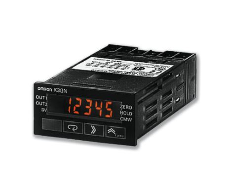


Итоговая стоимость доставки всего заказа
будет рассчитана на странице оформления заказа
-
Срок поставки
до 25-ти раб.дней! (из Китая!)
-
Минимальное количество поставки
0

Для этого продукта мы предлагаем дополнительные услуги, такие как
заказ запасных частей, ремонт, замена.
Индикаторы серии K3HB предназначены для решения самых разнообразных прикладных задач. Один из них, индикатор-измеритель веса, обеспечивает идеальную точность в любои системе взвешивания. Прибор может быть оснащен источником питания тензодатчика на 10 В/100 мА. В наличии имеются дополнительные платы интерфеисов связи, платы релеиных выходов и платы ввода сигналов событии. И вдобавок ко всему этому — возможность непосредственного подключения к сети DeviceNet.
•Высокая скорость измерения (измерительныи цикл 20 мс).
•Графическая шкала уровня.
•Двухцветная индикация для простого определения состояния процесса.
Аксессуары для панельных индикаторов-измерителей Omron
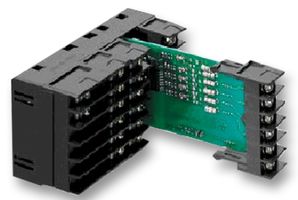
Цифровые панельные индикаторы-измерители Omron K3GN

Цифровые панельные индикаторы-измерители Omron K3HB-R
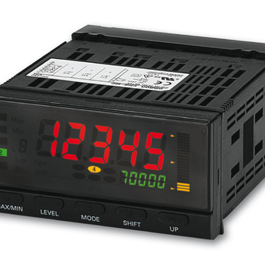
Цифровые панельные индикаторы-измерители Omron K3MA-J
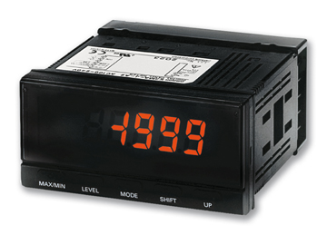
Игорь Осипов
★★★★★
25.01.2020
Квалифицированный штат сотрудников
Артем Макаров
★★★★★
11.03.2019
От лица нашей компании, благодарю Магистраль Энерго Инжиниринг за оперативную поддержку по всем вопросам, касающимся поставки оборудования для атомной отрасли.
Компания Гранд Ремонт
★★★★★
12.02.2019
Регормендуем, как хорошего поставщика оборудования Siemens, Schneider Electric, ДКС. Заказывали в разные города, где работают наши офисы, везде доставлено в указанные сроки, без браков и путаницы.
ЛитМаш Завод
★★★★★
22.11.2018
По результатам проведенного энергетического обследования, хотим отметить высокий профессионализм сотрудников компании, экспертное понимание технической и экономической составляющей, доброжелательное общение.
money maker
★★★★★
29.10.2018
Профессиональный подход к делу. Сотрудников данной компании отличает умение быстро найти оптимальное решение ценовых проблем, а так же скорость реакций на наши запросы и предоставления ответов на них.
IT-BI IO
★★★★★
17.10.2018
Сотрудничали с этой компанией по вопросу проведения энергетического обследования для получения энергопаспорта. Сотрудники компании проявили компетентность в технических вопросах, помогли решить сопутствующие технические задачи и гибко подошли к ценовой политике. Рекомендую.
Alya Go
★★★★★
14.09.2018
Выражаем благодарность сервис-инженерам компании «МагистральЭнергоИнжиниринг» за оперативную поддержку в устранении технических сбоев в работе контроллера SIMATIC S7-300. Работоспособность оборудования полностью восстановлена, работа выполнена качественно, оперативно и с учетом всех наших пожеланий.
Сергей Олехов
★★★★★
12.09.2018
Грамотные технические специалисты. Рекомендую как ответственного поставщика.
ЕА Кармацких
★★★★★
07.08.2018
Сотрудников данной компании отличает умение быстро найти оптимальное решение ценовых проблем, а так же скорость реакций на наши запросы и предоставления ответов на них.
Yuriy
★★★★★
29.03.2018
Работали в 2017 г. по поставке серверного оборудования HP — по всем вопросам в компании оказывали поддержку — от приема заявки до поставки. Технические специалисты показали себя компетентным товарищами- помогли подобрать необходимое оборудование: Сервер, коммутаторы, маршрутизаторы, съемные ЖД на 3 Трб. А самое главное все быстро — мы разместили заказ — на след. день — пришло уведомление о поступлении платежа, а через 2 дня пришло автоматическое уведомление о доставке. Доставка до дверей. Сроки соблюдены! Могу с уверенностью рекомендовать компанию как хорошего поставщика. Мы работаем с ними и по сей день!

K3HB-SSD AC/DC24, Индикатор линейного датчика серии K3HB, вход процесса постоянного тока, напряжение питания 24 V AC/DC
K3MA-J-A2 24AC/DC, Измеритель процессов серии K3MA, входной сигнал — постоянный ток/напряжение постоянного тока, 2 релейных выхода (SPST-NO), напряжен
K33-FLK3B, Дополнительная панель с источником питания датчика (10 В=, 100 мА) и RS-485, для цифровых измерителей серии K3HB-X
K3HB-XAD 100-240VAC, Измеритель параметров процесса серии K3HB, вход постоянного тока, напряжение питания 100..240 V AC
K3HB-VLC 24VAC/VDC, Измеритель веса серии K3HB, вход от тензодатчика, напряжение питания 24 V AC/DC
K3HB-XAD 24VAC/VDC, Измеритель параметров процесса серии K3HB, вход постоянного тока, напряжение питания 24 V AC/DC
K33-L2A, Плата выхода цифрового индикатора K3_
K3MA-L-C 24AC/DC, Измеритель температуры серии K3MA, входной сигнал -термосопротивление/термопара, релейный выход (SPDT), напряжение питания 24 V AC/D
K33-L1B, Дополнительная панель с источником питания датчика (10 В=, 100 мА) и линейным выходом тока (0(4) ? 20 мА, 0(1) — 5 В, 0 — 10 В), для цифровых
K3GN-PDT2 24VDC, Цифровой панельный индикатор-измеритель серии K3GN, входной сигнал — постоянный ток/напряжение постоянного тока, PNP, 3 транзисторных
K3MA-J 100-240AC, Измеритель процессов серии K3MA, входной сигнал — постоянный ток/напряжение постоянного тока, напряжение питания 100..240 V AC
K3HB-RPB 24VAC/VDC, Индикатор-измеритель частоты/скорости вращения серии K3HB, вход PNP, напряжение питания 24 V AC/DC
K33-B, Дополнительная панель с источником питания датчика (10 В=, 100 мА) для цифровых измерителей серии K3HB-X
K3HB-RPB 100-240VAC, Индикатор-измеритель частоты/скорости вращения серии K3HB, вход PNP, напряжение питания 100..240 V AC
K32-BCD, Плата выхода цифрового индикатора K3_
K3HB-XAA 100-240VAC, Измеритель параметров процесса серии K3HB, вход переменного тока, напряжение питания 100..240 V AC
K3MA-F-A2 24AC/DC, Цифровой измеритель частоты/скорости серии K3MA, импульсный входной сигнал, 2 релейных выхода (SPST-NO), напряжение питания 24 V AC
K33-CPB, Дополнительная панель с источником питания датчика (10 В=, 100 мА) и выходом реле (SPDT), для цифровых измерителей серии K3HB-X
K3MA-L-C 100-240AC, Измеритель температуры серии K3MA, входной сигнал -термосопротивление/термопара, релейный выход (SPDT), напряжение питания 100..24
K34-DRT, Дополнительная панель с DeviceNet, для цифровых измерителей серии K3HB