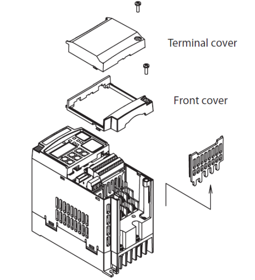
Схема открывания защитных крышек
Особенности
- Пусковой крутящий момент до 200% на частотах близких к 0.5 Гц
- Двойная шкала мощности VT-переменный момент нагрузки с перегрузкой до 120% в течении 1мин и CT-постоянный момент нагрузки с перегрузкой до 150% в течении 1мин
- Управление двигателем с короткозамкнутым ротором или постоянными магнитами на роторе
- Безопасность в соответствии с ISO13849-1 Категория 3
- Встроенный программируемый логический контроллер ПЛК
- RS485 интерфейс для связи «Инвертор-Инвертор» или ModBus
- Режим позиционирования
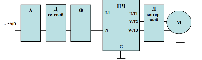
Схема подключения входного сетевого питания и мотора
- Преобразователь частоты с однофазным напряжением питания (MX2-AB***-E) 220В.
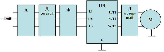
2. Преобразователь частоты с трехфазным напряжением питания (MX2-A4***-E) 380В.
Клеммы цепи управления
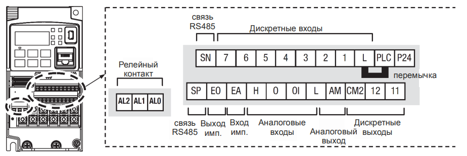
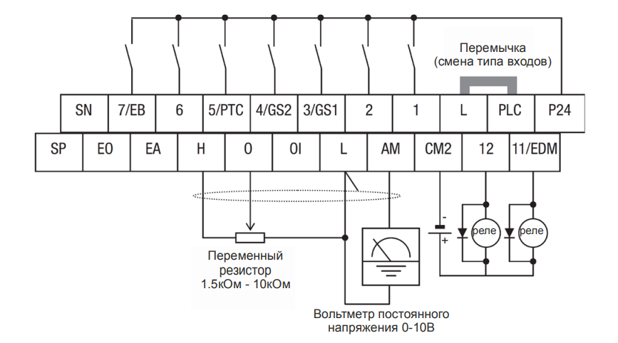
Спецификация клемм управления и сигнализации.
| Обозначение клеммы | Описание | Номинальная характеристика. Примечания |
| P24 | +24В для логических входов | +24В для питания логических входов. Максимальный ток 100мА. Не подключайте к питающей сети или заземлению. Не соединяйте с клеммой L. |
| PLC | Общая клемма логических входов | Заводская установка: истоковый тип (PLC соединена с L) клемма Р24 – опорное напряжение для входов 1-7. Для изменения типа входов нужно установить перемычку на клеммы PLC и P24, в этом случае клемма L – опорное напряжение для входов 1-7 |
| 1, 2, 3/GS1, 4/GS2, 5/PTC, 6, 7/EB |
Программируемые дискретные логические входы | Напряжение относительно клеммы PLC: Включение 18В и более, Выключение 3В и меньше, Максимальное допустимое 27В, Потребляемый ток входа 5мА (при 24В) |
| GS1 (3) | Вход безопасной остановки GS1 | Функционирование основано на ISO13849-1 |
| GS2 (4) | Вход безопасной остановки GS2 | Функционирование основано на ISO13849-1 |
| PTC (5) | Вход для термистора мотора | Подключите термистор мотора между клеммами PTC и L и установите функцию 19 в параметре С005. Авария происходит если температура мотора возросла на столько, что сопротивление превышает 3кОм. |
| EB (7) | Вход В последовательности импульсов | Максимум 2 кГц. Относительно клеммы PLC. |
| EA | Вход А последовательности импульсов | Максимум 32 кГц. Относительно клеммы L. |
| L (верхний ряд) | Общая для дискретных входов | Общая для клемм 1 ÷ 7. Не заземлять. |
| 11/EDM | Дискретный логический выход, имеющий двойную функцию | Тип – открытый коллектор, максимальный ток: 50мА, Максимальное напряжение: 27В, относительно клеммы CM2. Функционирование EDM основано на ISO13849-1 |
| 12 | Дискретный логический выход | Тип – открытый коллектор, максимальный ток: 50мА, Максимальное напряжение: 27В, относительно клеммы CM2. |
| CM2 | Общая для дискретных выходов | 100мА, общий ток выходов 11 и 12 |
| АМ | Аналоговый выход напряжения | 0-10В пост., 1мА максимум |
| ЕО | Выход импульсный | 10В пост., 2мА макс, 32кГц макс |
| L (нижний ряд) | Общая для аналоговых сигналов | Проходит общий ток клемм OI, O и Н |
| OI | Аналоговый вход для токового сигнала | 4 – 19.6мА диапазон, 20мА номинал, Внутреннее сопротивление 250Ом |
| O | Аналоговый вход для сигнала напряжения | 0 – 9.8В диапазон, 10В номинал, Внутреннее сопротивление 10кОм |
| H | +10В для аналоговых входов | 10В номинал, 10мА макс. |
| SP, SN | Клеммы сетевого подключения | Для сети ModBus по RS485 |
| AL0 | Общий контакт реле аварийной сигнализации | 250 VAC 2.5 A (актив) мaкс. 250 VAC 0.2 A (индуктив) макс. 100 VAC 10 mA мин. 30 VDC 3.0 A (актив) max. 30 VDC 0.7 A (индуктив) макс. 5 VDC 100 mA мин. |
| AL1 | Контакт реле. Нормально открыт. |
250 VAC 2.5 A (актив) мaкс. 250 VAC 0.2 A (индуктив) макс. 100 VAC 10 mA мин. 30 VDC 3.0 A (актив) max. 30 VDC 0.7 A (индуктив) макс. 5 VDC 100 mA мин. |
| AL3 | Контакт реле. Нормально закрыт. |
250 VAC 2.5 A (актив) мaкс. 250 VAC 0.2 A (индуктив) макс. 100 VAC 10 mA мин. 30 VDC 3.0 A (актив) max. 30 VDC 0.7 A (индуктив) макс. 5 VDC 100 mA мин. |
Примечания:
- Обе клеммы L соединены между собой внутри инвертора.
- Рекомендуем использовать клемму L (верхний ряд) как общий для дискретных входов и L (нижний ряд) как общий для аналоговых входов/выходов.
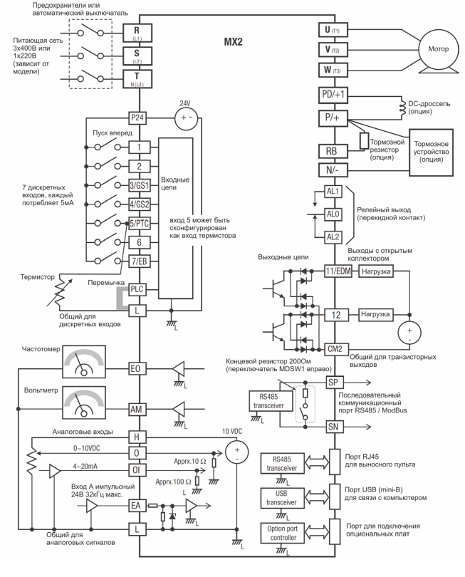
Общая схема соединений
Cхема подключения питания, двигателя, дискретных и аналоговых входов и выходов.
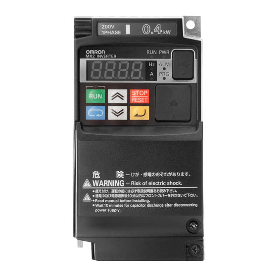
Элементы пульта оператора
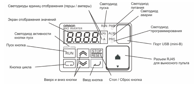
- Светодиод пуска – загорается при подаче команды на запуск двигателя во время начала вращения и отключается при остановке мотора.
- Светодиод программирования – загорается при готовности к изменению значений параметров и отключается в режиме контроля текущих параметров.
- Светодиод активности кнопки пуск – загорается при активированной кнопке и возможности с нее подать команду на запуск мотора.
- Кнопка пуска Run – при нажатии производится запуск двигателя (сначала должен светиться светодиод над кнопкой). Направление вращения двигателя можно задавать через функцию F004.
- Кнопка Stop/Reset – при нажатии производится остановка двигателя (при этом используется значение времени замедления), а также, происходит сброс возникающих ошибок.
- Экран отображения значений – 4-х разрядный, 7-ми сегментный индикатор для программирования и отображения параметров и текущих значений.
- Светодиоды: Hz, A – загораются при отображении на экране частоты или тока, соответственно.
- Светодиод Power – загорается при подаче питания на инвертор.
- Светодиод Alarm – загорается, когда инвертор в состоянии “Сбой”.
- Кнопка цикла – используется для входа в режим программирования, перемещения по группам параметров и функций.
- Кнопки вверх и вниз – используются для перемещения вверх/вниз по списку внутри 1 группы параметров и функций отображаемых на индикаторе и для изменения их значений.
- Кнопка ввода – используется для входа в отображаемый параметр или функцию, для выхода из нее с сохранением установленного значения в памяти EEPROM.
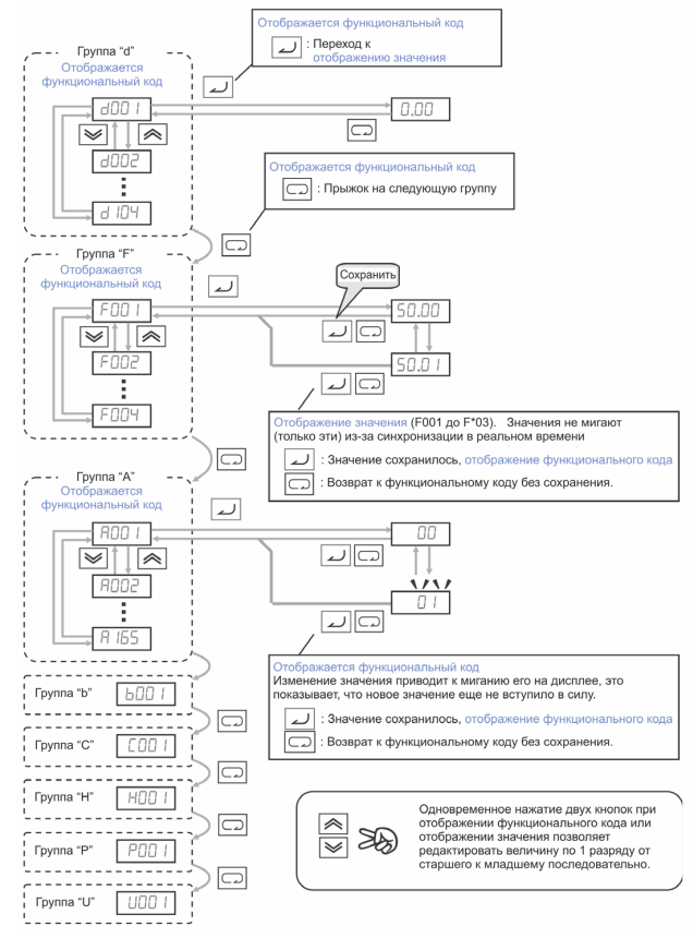
Порядок работы со списком параметров и функций
Коды ошибок
Преобразователи частоты серии МХ2 имеют защиту от перегрузки по току, от повышенного/ пониженного напряжения и много других. При срабатывании защиты отключается выход инвертора и остановка двигателя происходит в режиме свободного выбега. Перезагрузка частотного преобразователя и сброс ошибки производится нажатием кнопки STOP/RESET.
| Код ошибки | Наименование | Возможные причины сбоя |
| E01 | Защита от перегрузки по току при постоянной скорости | Замыкание на выходе инвертора Блокировка вала двигателя Слишком большая нагрузка Неправильно совершено подключение мотора Замечание: для серии SJ200 защита от перегрузки по току будет срабатывать при перегрузке 200% от номинального тока |
| E02 | Защита от перегрузки по току при замедлении | Замыкание на выходе инвертора Блокировка вала двигателя Слишком большая нагрузка Неправильно совершено подключение мотора Замечание: для серии SJ200 защита от перегрузки по току будет срабатывать при перегрузке 200% от номинального тока |
| E03 | Защита от перегрузки по току при разгоне | Замыкание на выходе инвертора Блокировка вала двигателя Слишком большая нагрузка Неправильно совершено подключение мотора Замечание: для серии SJ200 защита от перегрузки по току будет срабатывать при перегрузке 200% от номинального тока |
| E04 | Защита от перегрузки по току при других условиях | Установлен слишком большой тормозной момент (А054) Влияние электромагнитных помех на трансформатор тока |
| E05 | Защита от перегрузки | Электронное тепловое реле определило перегрев мотора |
| E06 | Защита от перегрузки тормозного резистора | Превышается время или коэффициент использования регенеративного торможения, слишком большой ток торможения |
| E07 | Защита от повышенного напряжения | Энергия, отдаваемая двигателем при торможении, вызывает увеличение напряжения в контуре постоянного тока выше порогового значения |
| E08 | Ошибка EEPROM | Влияние электромагнитных помех или высокой температуры на встроенную память EEPROM |
| E09 | Защита от пониженного напряжения | Пониженное напряжение в контуре постоянного тока может вызвать неправильное функционирование инвертора |
| E10 | Ошибка измерения тока | Выход из строя цепей измерения потребляемого мотором тока |
| E11 | Ошибка CPU | Сбои в работе микропроцессорного модуля CPU |
| E12 | Сбой во внешней цепи | Подан сигнал на дискретный вход с функцией [EXT] (сбой в работе внешнего устройства) |
| E13 | USP – предотвращение перезапуска при восстановлении питания | Когда на инвертор подаётся питание при наличии команды Пуск мотора происходит сбой с блокировкой возможность запуска пока не сброшен сбой, если активна функция USP |
| E14 | Защита от замыкания на землю | Замыкание на землю между выходом инвертора и корпусом мотора (заземлением) в момент теста питания (между подачей питания на ПЧ и пуском мотора). Данная функция обеспечивает защиту инвертора, но не людей. |
| E15 | Защита от повышенного напряжения на входе | Сетевое напряжение превышало допустимое значение в течение 100сек режима Стоп. |
| E21 | Тепловая защита | Внутренняя температура инвертора (силового модуля) превышает пороговое значение. |
| E22 | Ошибка связи с CPU | Ошибка связи между двумя процессорами |
| E25 | Авария основных цепей | Влияние помех или повреждение цепей основных элементов |
| E30 | Ошибка драйвера | Внутренняя ошибка в цепях защиты между CPU и драйвером из-за влияния помех или повреждения. |
| E35 | Термисторная защита | Происходит если термистор, подключенный к клеммам 5 (с функцией ТНМ) и L слишком сильно нагрелся |
| E36 | Ошибка тормоза | Происходит если в b120 установлен 01 и не получен сигнал подтверждения от тормоза после истечения времени b124. Или когда выходной ток не достигает значения b126 в течение времени b121 |
| E37 | Безопасный стоп | Подан сигнал безопасного стопа |
| E38 | Защита от перегрузки на маленькой скорости | Перегрузка во время работы мотора на очень маленькой скорости |
| E40 | Ошибка пульта оператора | Проблема связи между инвертором и клавиатурой пульта оператора |
| E41 | Ошибка связи сети ModBus | Если С076=00 и произошла проблема связи в сети ModBus |
| E43 | Некорректная инструкция в программе EzSQ | Программа сохраненная в памяти инвертора уничтожена, или терминал PRG был включен без программы загруженной в инвертор. |
| E44 | Ошибка счета в программе EzSQ | Подпрограммы, if-условия, или for-циклы вложены в более чем в восемь уровней |
| E45 | Ошибка инструкции в программе EzSQ | Инвертор обнаруживал команду, которая не может быть выполнена (взаимопротиворечие). |
| E50 – E59 | Пользовательские ошибки (0 – 9) в программе EzSQ | Ошибка пользователя, заложенная в программе EzSQ |
| E60 – E69 | Ошибки в подключенных опциональных платах | Детальные пояснения каждой из ошибок в инструкции к опциональной плате |
| E80 | Отключение энкодера | Если провода энкодера разъединены, обнаружена ошибка подключения, повреждение энкодера или выходной сигнал энкодера не поддерживается преобразователем |
| E81 | Превышение скорости | Скорость мотора выше значения А004хР026 |
| E82 | Ошибка диапазона позиционирования | Если текущая позиция превышает диапазон позиционирования P072-P073 |
Скачать полную документацию.
RU
ENG
-
Contents
-
Table of Contents
-
Troubleshooting
-
Bookmarks
Quick Links
Cat. No. I570-E2-02A
MX2
Born to drive machines
Model: 3G3MX2
200 V Class Three-Phase Input 0.1 to 15 kW
200 V Class Single-Phase Input 0.1 to 2.2 kW
400 V Class Three-Phase Input 0.4 to 15 kW
USER´S MANUAL
Related Manuals for Omron 3G3MX2
Summary of Contents for Omron 3G3MX2
-
Page 1
Cat. No. I570-E2-02A Born to drive machines Model: 3G3MX2 200 V Class Three-Phase Input 0.1 to 15 kW 200 V Class Single-Phase Input 0.1 to 2.2 kW 400 V Class Three-Phase Input 0.4 to 15 kW USER´S MANUAL… -
Page 3
OMRON. No patent liability is assumed with respect to the use of the information contained herein. Moreover, because OMRON is con- stantly striving to improve its high-quality products, the information contained in this manual is subject to change without notice. -
Page 4
WAY CONNECTED WITH THE PRODUCTS, WHETHER SUCH CLAIM IS BASED ON CONTRACT, WARRANTY, NEGLIGENCE, OR STRICT LIABILITY. In no event shall the responsibility of OMRON for any act exceed the individual price of the product on which liability is asserted. -
Page 5
PROGRAMMABLE PRODUCTS OMRON shall not be responsible for the user’s programming of a programmable product, or any consequence thereof. Disclaimers CHANGE IN SPECIFICATIONS Product specifications and accessories may be changed at any time based on improvements and other reasons. It is our practice to change model numbers when published ratings or features are changed, or when significant construction changes are made. -
Page 6: Table Of Contents
Table of contents Safety Messages …………. Hazardous High Voltage .
-
Page 7: Table Of Contents
Omron EMC Recommendations ……..
-
Page 8: Safety Messages
Safety Messages For the best results with the MX2 Series inverter, carefully read this manual and all of the warning labels attached to the inverter before installing and operating it, and follow the instructions exactly. Keep this manual handy for quick reference.
-
Page 9
!WARNING The user is responsible to ensure that all driven machinery, drive train mecha- nism not supplied by OMRON, and process line material are capable of safe operation at an applied frequency of 150% of the maximum selected fre- quency range to the AC motor. Failure to do so can result in destruction of equipment and injury to personnel should a single-point failure occur. -
Page 10
General Precautions — Read These First! !WARNING Rotating shafts and above-ground electrical potentials can be hazardous. Therefore, make sure that all electrical work conform to the National Electrical Codes and local regulations. Installation, alignment and maintenance must be performed only by qualified personnel. !Caution a) Class I motor must be connected to earth ground via low resistive path (<0.1) -
Page 11: Index To Warnings And Cautions In This Manual
Index to Warnings and Cautions in This Manual Index to Warnings and Cautions in This Manual Cautions and Warnings for Orientation and Mounting Procedures !HIGH VOLTAGE Hazard of electrical shock. Disconnect incoming power before changing wir- ing, put on or take off optional devices or replace cooling fans. Wait ten (10) minutes before removing the front cover.
-
Page 12
“USE 60/75 C Cu wire only” or equivalent. For models 3G3MX2-AB004, -AB007, -AB022, -A2015, -A2022, -A2037, -A2055, -A2075…… 45 !WARNING “USE 75 C Cu wire only” or equivalent. For models 3G3MX2-AB002, -AB004, A2002, -A2004, -A2007, -A4022, -A4030, -A4040, -A4055, -A4075… 45 !WARNING “USE 60 C Cu wire only”… -
Page 13
Index to Warnings and Cautions in This Manual Wiring — Cautions for Electrical Practice !Caution Fasten the screws with the specified fastening torque in the table provided. Check for any loose screws. Otherwise, there is danger of fire….46 !Caution Be sure that the input voltage matches the inverter specifications;… -
Page 14
Index to Warnings and Cautions in This Manual !Caution Remarks for using ground fault interrupter breakers in the main power supply: Adjustable frequency inverter with integrated CE-filters and shielded (screened) motor cables have a higher leakage current toward earth GND. Especially at the moment of switching ON this can cause an inadvertent trip of ground fault interrupters. -
Page 15
Index to Warnings and Cautions in This Manual !WARNING Be sure not to operate electrical equipment with wet hands. Otherwise, there is the danger of electric shock…………..… 192 !WARNING While the inverter is energized, be sure not to touch the inverter terminals even when the motor is stopped. -
Page 16
Index to Warnings and Cautions in This Manual !Caution The operation of the inverter can be easily changed from low speed to high speed. Be sure to check the capability and limitations of the motor and machine before operating the inverter. Otherwise, it may cause injury to per- sonnel. -
Page 17: General Warnings And Cautions
General Warnings and Cautions !Caution Do not connect the megger to any control circuit terminals such as intelligent I/O, analog terminals, etc. Doing so could cause damage to the inverter. !Caution Never test the withstand voltage (HIPOT) on the inverter. The inverter has a surge protector between the main circuit terminals above and the chassis ground.
-
Page 18
General Warnings and Cautions !Caution Do not stop operation by switching OFF electromagnetic contactors on the primary or secondary side of the inverter. Ground fault interrupter Power Inverter Input L1, L2, L3 U, V, W Motor When there has been a sudden power failure while an operation instruction is active, then the unit may restart operation automatically after the power failure has ended. -
Page 19
General Warnings and Cautions !Caution EFFECTS OF POWER DISTRIBUTION SYSTEM ON INVERTER In the case below involving a general-purpose inverter, a large peak current can flow on the power supply side, sometimes destroying the converter mod- ule: 1. The unbalance factor of the power supply is 3% or higher. 2. -
Page 20: Precautions For Safe Use
Precautions for Safe Use !Caution When using normally closed active state settings (C011 to C017) for exter- nally commanded Forward or Reverse terminals [FW] or [RV], the inverter may start automatically when the external system is powered OFF or discon- nected from the inverter! So do not use normally closed active state settings for Forward or Reverse terminals [FW] or [RV] unless your system design pro- tects against unintended motor operation.
-
Page 21
Underwriters Laborato- ries guidelines. !WARNING Use 60/75 C Cu wire only. (for models: 3G3MX2-A2001, -A2002, -A2004, -A2007, -AB015, -AB022, -A4004, -A4007, -A4015, -A4022, -A4030) !WARNING Use 75 C Cu wire only. (for models: 3G3MX2-AB001, -AB002, -AB004,… -
Page 22
® Cautions, Warnings and Instructions !WARNING When protected by CC, G, J, or R class Fuses, or when Protected By A Circuit Breaker Having An Interrupting Rating Not Less Than 100,000 rms Symmetri- cal Amperes, 240 or 480 Volts Maximum. !WARNING Install device in pollution degree 2 environment. -
Page 23
® Cautions, Warnings and Instructions Terminal symbols and Screw size Inverter Model Screw Size Required Wire range Torque (N-m) 3G3MX2-AB001, AWG16 (1.3mm 3G3MX2-AB002, 3G3MX2-AB004 3G3MX2-AB007 AWG12 (3.3mm 3G3MX2-AB015, AWG10 (5.3mm 3G3MX2-AB022 3G3MX2-A2001, AWG16 (1.3mm 3G3MX2-A2002, 3G3MX2-A2004, 3G3MX2-A2007 3G3MX2-A2015 AWG14 (2.1mm 3G3MX2-A2022 AWG12 (3.3mm… -
Page 24
Fuse Sizes The inverter shall be connected with a UL Listed Cartridge Nonrenewable fuse, rated 600Vac with the current ratings as shown in the table below. Inverter Model Type Rating 3G3MX2-AB001, Class J 10A, AIC 200kA 3G3MX2-AB002, 3G3MX2-AB004 3G3MX2-AB007 15A, AIC 200kA… -
Page 25: Revision History
Revision History Revision History A manual revision history appears as a suffix to the catalogue number located at the lower left of the front and back covers. I570-E2-02 Cat. No. Revision code Revision code Revision date Description 2009 First version Second version January 2013 New functionality and IP54 models…
-
Page 26
Revision History xxiv… -
Page 27: Getting Started
• Continuous operation at 100% torque within a 1:10 speed range (6/60 Hz/ 5/50 Hz) without motor derating. • Fan has ON/OFF selection to provide longer life for cooling fan. A full line of accessories from Omron is available to complete your motor application: • Integrated USB port for PC communication •…
-
Page 28
1-1-2 Inverter Specification Label The Omron MX2 inverters have product labels located on the right side of the housing, as pictured below. Be sure to verify that the specifications on the labels match your power source, and application safety requirements. -
Page 29: Mx2 Inverter Specifications
Note that General Specifications on page 7 in this chap- ter apply to both voltage class groups. Footnotes for all specification tables fol- low the table below. Item Single-phase 200 V class Specifications 3G3MX2 inverters, 200 V models AB001 AB002 AB004F AB007 AB015…
-
Page 30
Note 11 Conforms to the test method specified in JIS C0040 (1999). For the model types excluded in the standard specifications, contact your Omron sales rep- resentative. Note 12 Watt losses are calculated values based on specification of main semi-con- ductors. -
Page 31
MX2 Inverter Specifications Section 1-2 Item Three-phase 200V class Specifications 3G3MX2 inverters, 200 V models A2001 A2002 A2004 A2007 A2015 A2022 Applica- 0.75 ble motor 0.75 size *2 Rated 200 V capacity (kVA) 240 V Loss at 100% load Efficiency at rated load % 89.5… -
Page 32
MX2 Inverter Specifications Section 1-2 Item Three-phase 400V class Specifications 3G3MX2 inverters, 400 V models A4004 A4007 A4015 A4022 A4030 A4040 Applica- 0.75 ble motor 0.75 size *2 Rated 380 V capacity (kVA) 480 V Loss at 100% load Efficiency at rated load % Rated input voltage Three-phase: 380 V-15% to 480 V+10%, 50/60 Hz±5%… -
Page 33: General Specifications
MX2 Inverter Specifications Section 1-2 1-2-2 General Specifications The following table applies to all MX2 inverters. Item General Specifications Protective housing IP 20 Control method Sinusoidal Pulse Width Modulation (PWM) control Carrier frequency 2 kHz to 15 kHz (derating required depending on the model) Output frequency range 0.1 to 400 Hz Frequency accuracy…
-
Page 34
MX2 Inverter Specifications Section 1-2 Item General Specifications Output signal Intelligent output terminal RUN (run signal), FA1~FA5 (frequency arrival signal), OL,OL2 (overload advance notice signal), OD (PID deviation error signal), AL (alarm signal), 48 functions assignable OTQ (over/under torque threshold), UV (under-voltage), TRQ (torque limit signal), RNT (run time expired), ONT (power ON time expired), THM (ther- mal warning), BRK (brake release), BER (brake error), ZS (0Hz detection), DSE (speed deviation excessive), POK (positioning completion), ODc… -
Page 35: Derating Curves
MX2 Inverter Specifications Section 1-2 1-2-3 Signal Ratings Detailed ratings are in . Signal / Contact Ratings Built-in power for inputs 24V DC, 100 mA maximum Discrete logic inputs 27 VDC maximum Discrete logic outputs 50 mA maximum ON state current, 27 VDC maximum OFF state voltage Analog output 10bit / 0 to 10 VDC, 1 mA…
-
Page 36
The following table shows which models need derating. 1-ph Derating 3-ph Derating 3-ph Derating 200V class 200V class 400V class 3G3MX2-AB001 – 3G3MX2-A2001 – 3G3MX2-A4004 – 3G3MX2-AB002 – 3G3MX2-A2002 O 3G3MX2-A4007 O 3G3MX2-AB004 O 3G3MX2-A2004 O 3G3MX2-A4015 – 3G3MX2-AB007 –… -
Page 37
MX2 Inverter Specifications Section 1-2 3G3MX2-AB004 CT (3.0 A) VT (3.5 A) output current 8 10 12 16 kH 8 10 12 14 kH Carrier frequency Carrier frequency 3G3MX2-A2004 CT (3.0 A) VT (3.5 A) 40°C individual 40°C side-by-side 40°C individual output current 40°C side-by-side… -
Page 38
MX2 Inverter Specifications Section 1-2 3G3MX2-A4040 CT (9.2 A) VT (11.1 A) 40°C individual 40°C individual 40°C side-by-side 40°C side-by-side output current 8 10 12 16 kH 8 10 12 14 kH Carrier frequency Carrier frequency 3G3MX2-A2075 CT (33.0 A) VT (40.0 A) -
Page 39
MX2 Inverter Specifications Section 1-2 3G3MX2-A4110 CT (24.0 A) VT (31.0 A) 50°C individual output current 40°C side-by-side 8 10 12 16 kH 8 10 12 14 kH Carrier frequency Carrier frequency 3G3MX2-A2150 CT (60.0 A) VT (69.0 A) output current 50°C individual… -
Page 40: Introduction To Variable-Frequency Drives
1-3-1 The Purpose of Motor Speed Control for Industry Omron inverters provide speed control for 3-phase AC induction motors. You connect AC power to the inverter, and connect the inverter to the motor. Many applications benefit from a motor with variable speed, in several ways: •…
-
Page 41
1-3-4 Inverter Input and Three-phase Power The Omron MX2 Series of inverters includes two sub-groups: the 200 V class and the 400V class inverters. The drive described in this manual may be used in either the United States or Europe, although the exact voltage level for com- mercial power may be slightly different from country to country. -
Page 42
Introduction to Variable-Frequency Drives Section 1-3 The Omron inverter is a rugged and reliable device. The intention is for the inverter to assume the role of controlling power to the motor during all normal operations. Therefore, this manual instructs you not to switch off power to the inverter while the motor is running (unless it is an emergency stop). -
Page 43
Introduction to Variable-Frequency Drives Section 1-3 1-3-8 Velocity Profiles The MX2 inverter is capable of Speed Set speed sophisticated speed control. graphical representation that Accel Decel capability will help you understand and configure the associated param- eters. This manual makes use of the Velocity Profile velocity profile graph used in indus- try (shown at right). -
Page 44: Frequently Asked Questions
Frequently Asked Questions Section 1-4 Frequently Asked Questions Q. What is the main advantage in using an inverter to drive a motor, com- pared to alternative solutions? A. An inverter can vary the motor speed with very little loss of efficiency, unlike mechanical or hydraulic speed control solutions.
-
Page 45
Q. How many poles should the motor have? A. Omron inverters can be configured to operate motors with 2, 4, 6, or 8 poles. The greater the number of the poles, the slower the top motor speed will be, but it will have higher torque at the base speed. -
Page 46: International Standards
Low-voltage directive EN 61800-5-1 EMC directive EN 61800-3 UL508C CSA-C22.2 No. 14 Safety functions are supported. The 3G3MX2 series inverters meet requirements for IEC 60204-1 Stop Cate- gory 0 operation and ISO 13849-1 Performance Level PLd of the Machinery Directive.
-
Page 47: Inverter Mounting And Installation
SECTION 2 Inverter Mounting and Installation Orientation to Inverter Features 2-1-1 Unpacking and Inspection Please take a few moments to unpack your new MX2 inverter and perform these steps: 1. Look for any damage that may have occurred during transportation. 2.
-
Page 48
Orientation to Inverter Features Section 2-1 Power Wiring Access — First, ensure no power source is connected to the inverter. If power has been connected, verify that the Power LED is OFF and then wait ten minutes after power down to proceed. After removing the termi- nal cover and front housing cover, the housing partitions that cover the power and motor wiring exits will be able to slide upward as shown below. -
Page 49
Orientation to Inverter Features Section 2-1 2-1-3 User removable parts by each inverter size. IP20 1-phase 200 V 0.1, 0.2, 0.4 kW 3-phase 200 V 0.1, 0.2, 0.4, 0.75 kW Even if the W × H dimension is the same, the D dimension for the cooling fin varies depending on the capacity. -
Page 50
Orientation to Inverter Features Section 2-1 3-phase 200 V 3.7 kW 3-phase 400V 4.0 kW 3-phase 200 V 5.5, 7.5 kW 3-phase 400 V 5.5, 7.5 kW (1) Cooling fan cover (5) Terminal block cover (2) Cooling fan (6) Optional board cover (3) Cooling fin (7) Backing plate (4) Main housing… -
Page 51
Orientation to Inverter Features Section 2-1 3-phase 200 V 11 kW 3-phase 400 V 11, 15 kW 3-phase 200 V 15 kW (1) Cooling fan cover (5) Terminal block cover (2) Cooling fan (6) Optional board cover (3) Cooling fin (7) Backing plate (4) Main housing… -
Page 52
Orientation to Inverter Features Section 2-1 IP54 Mounting plate Air outlet Front cover Window for MX2 inverter display Lock for front cover USB connector (mini-B) Panel hole for accessory… -
Page 53
Orientation to Inverter Features Section 2-1… -
Page 54: Basic System Description
Basic System Description Section 2-2 Basic System Description A motor control system will obviously include a motor and inverter, as well as a circuit breaker or fuses for safety. If you are connecting a motor to the inverter on a test bench just to get started, that’s all you may need for now. But a system can also have a variety of additional components.
-
Page 55: Step-By-Step Basic Installation
Step-by-Step Basic Installation Section 2-3 !WARNING In the cases below involving a general-purpose inverter, a large peak current can flow on the power supply side, sometimes destroying the converter mod- ule: 1. The unbalance factor of the power supply is 3% or higher. 2.
-
Page 56
Step-by-Step Basic Installation Section 2-3 !Caution Be sure not to let the foreign matter enter vent openings in the inverter hous- ing, such as wire clippings, spatter from welding, metal shavings, dust, etc. Otherwise, there is the danger of fire. !Caution Be sure to install the inverter in a place that can bear the weight according to the specifications in the text (Chapter 1, Specifications Tables). -
Page 57
Step-by-Step Basic Installation Section 2-3 Mounting Orientation and Spacing Always install the housing in an upright position. Leave 10 cm space above and below the housing for proper cooling. Leave 10 cm space to the left and to the right for replacement of the dust filter. Removing the Front Cover !WARNING Turn off the power supply before removing the cover. -
Page 58
Step-by-Step Basic Installation Section 2-3 Ventilation fan Ventilation fan Inverter Inverter (Good example) (Bad example) Keep the Inverter away from heating elements (such as a Braking Resistor, reactor, etc.). Although side-by-side installation is possible. The ambient temperature of the installation site must not exceed 40C and the carrier frequency and output current must be derated if side-by-side installation is used. -
Page 59: Installation Method
Step-by-Step Basic Installation Section 2-3 2-3-3 Installation/Removal Method of the Terminal Block Cover 2-3-3-1 Removal method Loosen the screw(s) (1 or 2 While pressing the bottom of the locations) securing the terminal block cover in the direction terminal block cover. of the arrow, pull the terminal block cover downward to remove.
-
Page 60
Locate the applicable drawing on the following pages for your inverter. Dimen- sions are given in millimeters (inches) format. Ø4.5 8.8.8.8. Power Type W (mm) H (mm) D (mm) D1 (mm) Single-phase 3G3MX2-AB001 13.5 200V 3G3MX2-AB002 3G3MX2-AB004 122.5 3-phase 200 V 3G3MX2-A2001 13.5 3G3MX2-A2002 3G3MX2-A2004 122.5… -
Page 61
Step-by-Step Basic Installation Section 2-3 2-Ø4.5 8.8.8.8. Power Type W (mm) H (mm) D (mm) D1 (mm) Single-phase 3G3MX2-AB007 170.5 200 V 3G3MX2-AB015 3G3MX2-AB022 3-phase 200 V 3G3MX2-A2015 170.5 3G3MX2-A2022 3-phase 400V 3G3MX2-A4004 143.5 3G3MX2-A4007 170.5 3G3MX2-A4015 3G3MX2-A4022 3G3MX2-A4030… -
Page 62
Step-by-Step Basic Installation Section 2-3 2-Ø4.5 8.8.8.8. Power Type W (mm) H (mm) D (mm) D1 (mm) 3-phase 200 V 3G3MX2-A2037 170,5 3-phase 400 V 3G3MX2-A4040… -
Page 63
Step-by-Step Basic Installation Section 2-3 Ø 8.8.8.8. Power Type W (mm) H (mm) D (mm) D1 (mm) 3-phase 200 V 3G3MX2-A2055 73.3 3G3MX2-A2075 3-phase 400 V 3G3MX2-A4055 3G3MX2-A4075… -
Page 64
Step-by-Step Basic Installation Section 2-3 2- Ø 7 8.8.8.8. Power Type W (mm) H (mm) D (mm) D1 (mm) 3-phase 200 V 3G3MX2-A2110 3-phase 400 V 3G3MX2-A4110 3G3MX2-A4150… -
Page 65
Step-by-Step Basic Installation Section 2-3 2-Ø7 8.8.8.8. Power Type W (mm) H (mm) D (mm) D1 (mm) 3-phase 200 V 3G3MX2-A2150… -
Page 66
Step-by-Step Basic Installation Section 2-3 IP54 179.5 Figure 1 169.5 292.7 292.7 Figure 1 Power Type Single-phase 200 V 3G3MX2-DB001-E 3G3MX2-DB002-E 3G3MX2-DB004-E 3-phase 200 V 3G3MX2-D2001-E 3G3MX2-D2002-E 3G3MX2-D2004-E 3G3MX2-D2007-E 309.5 Figure 2 299.5 279.5 298.9 317.7 Figure 2 Power Type… -
Page 67
Step-by-Step Basic Installation Section 2-3 Figure 2 Power Type 3-phase 400 V 3G3MX2-D4004-EC 3G3MX2-D4007-EC 3G3MX2-D4015-EC 3G3MX2-D4022-EC 3G3MX2-D4030-EC 3G3MX2-D4040-EC Figure 3 299.5 Figure 3 Power Type 3-phase 200 V 3G3MX2-D2055-EC 3G3MX2-D2075-EC 3-phase 400 V 3G3MX2-D4055-EC 3G3MX2-D4075-EC Figure 4 18.7 329.7 Figure 4… -
Page 68
“USE 60/75 C Cu wire only” or equivalent. For models 3G3MX2-A2001, -A2002, -A2004, -A2007, -AB015, -AB022, -A4004, -A4007, -A4015, -A4022, -A4030 !WARNING “USE 75 C Cu wire only” or equivalent. For models 3G3MX2-AB001, -AB002, -AB004, -AB007, -A2015, -A2022, -A2037, A2055, A2075, -A2110, -A2150, -A4040, -A4055, -A4075, -A4110 and -A4150 !WARNING “Suitable for use on a circuit capable of delivering not more than 100k rms… -
Page 69
Step-by-Step Basic Installation Section 2-3 IP54 Connect all wiring via wiring access holes (in the botttom of the MX2 IP54 mounting plate). Connect the AC power supply voltage to the EMC filter. Connect the three phase motor to the motor output terminals of the MX2 inverter. -
Page 70
Step-by-Step Basic Installation Section 2-3 Note: Use IP54 or better cable glands to prevent moisture from entering the unit. Not doing so might result in damaging the unit. Note: Use cable glands of right size to prevent moisture from entering the unit. -
Page 71
Inverter Model Wiring Applicable equipment Power Lines Signal Lines Fuse (UL-rated, class J, 600 V) ¼ 3G3MX2-AB001 AWG16 / 1.3 mm² (75°C only) 18 to 28 AWG / 10 A 0.14 to ½ ¼ 3G3MX2-AB002 0.75 mm² 0.55 0.4 ¾… -
Page 72
Otherwise, there is the danger of fire. Types Screw Width (mm) Tightening Diameter Torque (N·m) 3G3MX2 — AB001, AB002, AB004 M3.5 3G3MX2 — A2001, A2002, A2004, A2007 3G3MX2 — AB007, AB015, AB022 3G3MX2 — A2015, A2022, A2037 3G3MX2 — A4004, A4007, A4015,… -
Page 73
Step-by-Step Basic Installation Section 2-3 2-3-9 Inverter output terminal (U/T1, V/T2, W/T3) For connection of the output terminal, use the compatible cable or a cable with a larger section. Otherwise, the output voltage between the Inverter and the motor may drop. Do not mount a phase advance capacitor or surge absorber, because these devices may cause the Inverter to trip or cause damage to the capacitor or surge absorber. -
Page 74
Step-by-Step Basic Installation Section 2-3 Single-phase 200 V 0.75 to 2.2 kW Three-phase 200 V 1.5, 2.2 kW Three-phase 400 V 0.4 to 3.0 kW Single-phase Three-phase RB PD/+1 P/+ N/- RB PD/+1 P/+ N/- N U/T1 V/T2 W/T3 R/L1 S/L2 T/L3 U/T1 V/T2 W/T3 Power input Output to Motor… -
Page 75
• Single-phase 200 to 240 V 50/60 Hz(0.1 kW~2.2 kW) for 3G3MX2-AB models • Three-phase 200 to 240 V 50/60 Hz (0.1 kW~15 kW) for 3G3MX2-A2 models • Three-phase 380 to 480 V 50/60 Hz (0.4 kW~15 kW) for 3G3MX2-A4 models !Caution Be sure not to power a three-phase-only inverter with single phase power. -
Page 76
Step-by-Step Basic Installation Section 2-3 !Caution Be sure not to connect an AC power supply to the output terminals. Other- wise, there is the possibility of damage to the inverter and the danger of injury and/or fire. MX2 Inverter Output to Motor Power Input !Caution Remarks for using ground fault interrupter breakers in the main power supply: Adjustable frequency inverter with integrated CE-filters and shielded… -
Page 77
Step-by-Step Basic Installation Section 2-3 2-3-12 Wire the Inverter Output to Motor Step 4 The process of motor selection is beyond the scope of this manual. However, it must be an AC induction motor with three phases. It should also come with a chassis ground lug. -
Page 78
Step-by-Step Basic Installation Section 2-3 MX2 control wiring quick reference (IP20) Breaker, MCCB or GFI (T1) Power source, (L1 ) Motor 3-phase or (T2) 1-phase, per inverter model (L2 ) (T3) N (L3 ) PD/+1 DC reactor Intelligent inputs, (optional) 7 terminals Forward NOTE:… -
Page 79
Step-by-Step Basic Installation Section 2-3 MX2 control wiring quick reference (IP54) Breaker, MCCB or GFI (T1) Power source, (L1 ) Motor 3-phase or (T2) 1-phase, per Filter (L2 ) inverter model (T3) N(L3 ) PD/+1 DC reactor (optional) Intelligent inputs, 7 terminals Forward NOTE:… -
Page 80
Step-by-Step Basic Installation Section 2-3 2-3-15 Name of Parts Inside the Terminal Block Cover Modbus-RTU Termination resistor selector switch Safety function selector switch Disable Enable (Factory default) (Factory default) USB connector (mini-B) Connector for optional board Connector for Digital Operator (RJ45) EDM function selector switch P1 terminal Multi-function contact terminal block… -
Page 81
Step-by-Step Basic Installation Section 2-3 2-3-16 Uncover the Inverter Vents Step 5 After mounting and wiring the inverter, Ventilation holes (top) remove any covers from the inverter hous- ing. This includes material over the side ven- tilation ports. !WARNING Make sure the input power to the inverter is OFF. -
Page 82: Powerup Test
3. Get an introduction to the use of the built-in operator keypad. The powerup test gives you an important starting to ensure a safe and suc- cessful application of the Omron inverter. We highly recommend performing this test before proceeding to the other chapters in this manual.
-
Page 83
Powerup Test Section 2-4 !Caution Check the following before and during the Powerup test. Otherwise, there is the danger of equipment damage. • Is the shorting bar between the [+1] and [+] terminals installed? DO NOT power or operate the inverter if the jumper is removed. •… -
Page 84: Using The Front Panel Keypad
Using the Front Panel Keypad Section 2-5 Using the Front Panel Keypad Please take a moment to familiarize yourself with the keypad layout shown in the figure below. The display is used in programming the inverter’s parame- ters, as well as monitoring specific parameter values during operation. (4) RUN LED (1) POWER LED (5) Monitor LED [Hz]…
-
Page 85
Using the Front Panel Keypad Section 2-5 2-5-1 Keys, Modes, and Parameters The purpose of the keypad is to provide a way to change modes and parameters. The term function applies to both monitoring modes and parameters. These are all acces- sible through function codes that are primary 4-character codes. -
Page 86
Using the Front Panel Keypad Section 2-5 2-5-2 Keypad Navigation Map The MX2 Series inverter drives have many programmable functions and parameters. Chapter 3 will cover these in detail, but you need to access just a few items to perform the powerup test. The menu structure makes use of function codes and parameter codes to allow programming and monitoring with only a 4-digit display and keys and LEDs. -
Page 87
Using the Front Panel Keypad Section 2-5 [Setting example] After power ON, changing from display to change the (carrier frequency) data. Data of d001 will be shown on the Press key to show display after the first power ON the function code 0.00 d001… -
Page 88
Using the Front Panel Keypad Section 2-5 2-5-3 Selecting Functions and Editing Parameters To prepare to run the motor in the powerup test, this section will show how to configure the necessary parameters: 1. Select the digital operator as the source of motor speed command (). -
Page 89
Using the Front Panel Keypad Section 2-5 If the Potentiometer Enable LED is OFF, follow these steps below (the table resumes action from the end of the previous table). Action Display Func./Parameter (Starting point) Speed command source setting A001 Run command source setting Press the A002 … -
Page 90
Using the Front Panel Keypad Section 2-5 To set the motor voltage, follow the steps on the following table. Action Display Func./Parameter (Starting point) Base frequency setting A003 AVR voltage select Press the key and hold until –> A082 Default value for AVR voltage: Press the A230 200 V class= 230 VAC… -
Page 91
Using the Front Panel Keypad Section 2-5 5. Set the Number of Motor Poles – The motor’s internal winding arrange- ment determines its number of magnetic poles. The specification label on the motor usually indicates the number of poles. For proper operation, verify the parameter setting matches the motor poles. -
Page 92
Using the Front Panel Keypad Section 2-5 2-5-4 Monitoring Parameters with the Display After using the keypad for parameter editing, it’s a good idea to switch the inverter from Program Mode to Monitor Mode. The PRG LED will be OFF, and the Hertz or Ampere LED indicates the display units. -
Page 93
Using the Front Panel Keypad Section 2-5 2-5-6 Single-Digit Edit Mode If a target function code or data is far from current data, using the single-digit edit mode makes it quicker. Pressing the up key and down key at the same time leads you to go into the digit-to-digit changing mode. -
Page 94
Note Some factory automation devices such as PLCs have alternative Run/Pro- gram modes; the device is in either one mode or the other. In the Omron inverter, however, Run Mode alternates with Stop Mode, and Program Mode alternates with Monitor Mode. -
Page 95: Configuring Drive Parameters
Choosing a Programming Device 3-1-1 Introduction Omron variable frequency drives (inverters) use the latest electronics technol- ogy for getting the right AC waveform to the motor at the right time. The bene- fits are many, including energy savings and higher machine output or productivity.
-
Page 96: Using The Keypad Devices
Using the Keypad Devices Section 3-2 Using the Keypad Devices The MX2 Series inverter front keypad contains all the elements for both moni- toring and programming parameters. The keypad layout is pictured below. All other programming devices for the inverter have a similar key arrangement and function.
-
Page 97
Using the Keypad Devices Section 3-2 3-2-2 Operational Modes The RUN and PRG LEDs tell just part of the story; Run Mode and Program Stop Modes are independent modes, not opposite modes. In the state diagram to the right, Run alternates with Stop, and Program Mode alternates with Monitor Mode. -
Page 98
Using the Keypad Devices Section 3-2 3-2-5 Dual Rate Selection The MX2 series inverter has Dual Rate, so that it can work in two different types of load condition, Constant torque application and Variable torque appli- cation. Select parameter depending on your application. -
Page 99
Using the Keypad Devices Section 3-2 Func. code Name Func. code Name C054 Over-torque/under-torque selection P033 Torque reference input selection C055 Overtorque level (FW, PW) P034 Torque reference setting C056 Overtorque level (RV, RG) P036 Torque bias mode C057 Overtorque level (RV, PW) P037 Torque bias value C058… -
Page 100: D» Group: Monitoring Functions
“D” Group: Monitoring Functions Section 3-3 “D” Group: Monitoring Functions You can access important parameter values with the “D” Group monitoring functions, whether the inverter is in Run Mode or Stop Mode. After selecting the function code number for the parameter you want to monitor, press the …
-
Page 101
“D” Group: Monitoring Functions Section 3-3 “D” Function Units Mode Func. Name Description Edit Code Power ON time monitor Displays total time the inverter has been pow- – hours ered up in hours. Range is 0 to 9999 / 1000 to 9999 / 100 to 999 (10,000 to 99,900) … -
Page 102
“D” Group: Monitoring Functions Section 3-3 “D” Function Units Mode Func. Name Description Edit Code Regenerative braking load rate Usage ratio of integrated brake chopper, – monitor range is 0.0~100.0 Electronic thermal monitor Accumulated value of electronic thermal –… -
Page 103
“D” Group: Monitoring Functions Section 3-3 3-3-2 Output Frequency Monitor [d001] Displays the output frequency of the inverter. During stop, “0.00” is displayed. The monitor LED indicator “Hz” is lit while the d001 setting is displayed. Parameter Default Function name Data Unit setting… -
Page 104
“D” Group: Monitoring Functions Section 3-3 3-3-5 PID Feedback Value Monitor [d004] When “01: Enabled” or “02: Reverse output enabled” is selected in PID Selection (A071), the PID feedback value can be monitored. Also, conversion is possible using PID Scale (A075). “d004 display”… -
Page 105
“D” Group: Monitoring Functions Section 3-3 3-3-7 Multi-function Output Monitor [d006] The LED lighting position indicates the output status of the multi-function output terminals. The output status of the built-in CPU is indicated. This is not the status of the control circuit terminal. -
Page 106
“D” Group: Monitoring Functions Section 3-3 3-3-9 Real Frequency Monitor [d008] The actual-frequency monitor d008 will reflect the real motor speed always that the encoder feedback is active by parameter P003=01, independently of parameter A044 and P012 settings. Parameter Default Function name Data Unit… -
Page 107
“D” Group: Monitoring Functions Section 3-3 3-3-13 Output Voltage Monitor [d013] Displays the output voltage of the inverter. Parameter Default Function name Data Unit setting d013 Output voltage monitor 0.0 to 600.0 • Set Motor Incoming Voltage Selection (A082/A282) correctly. The correct value may not be displayed. -
Page 108
“D” Group: Monitoring Functions Section 3-3 3-3-16 Total RUN Time [d016] Displays the total RUN time of the inverter. This parameter is saved in the EEPROM when the power is shut off. Parameter Default Function name Data Unit setting d016 Total RUN time 0.0 to 9,999. -
Page 109
“D” Group: Monitoring Functions Section 3-3 • The capacitor service life is calculated every 10 minutes. If the inverter is turned on/off frequently within this interval, the capacitor service life cannot be correctly diagnosed. • The cooling fan life assessment function is not available for 1-phase 200V class motors of 0.4 kW max. -
Page 110
“D” Group: Monitoring Functions Section 3-3 3-3-23 Inverter Mode [d060] Displays the current inverter mode. The inverter mode is changed using b171. Parameter Default Function name Data Unit setting d060 Inverter mode IM (induction motor) heavy load mode IM (induction motor) light load mode Permanent magnet motor control… -
Page 111
“D” Group: Monitoring Functions Section 3-3 3-3-26 Fault Frequency Monitor [d080] Displays the number of times the inverter has tripped. This number is saved in the EEPROM when the power is turned off. Parameter Default Function name Data Unit setting d080 Fault frequency monitor 0. -
Page 112
“D” Group: Monitoring Functions Section 3-3 3-3-30 Regenerative Braking Load Rate Monitor [d103] Displays a regenerative braking load rate. When the displayed value exceeds the value set in the Usage Rate of Regenerative Braking (b090), the inverter trips beacuse of “E06 (Braking resistor overload protection)”. Parameter Default Function name… -
Page 113
“D” Group: Monitoring Functions Section 3-3 3-3-34 PID Deviation Monitor [d153] It displays the PID deviation into d153 monitor. It only operates when PID function is effective (A071=01 or 02). Parameter Default Function name Data Unit setting d153 PID deviation monitor -9999.00 to 9999.00 A071 PID selection… -
Page 114
“D” Group: Monitoring Functions Section 3-3 3-3-36 Local Monitoring with Keypad Connected The MX2 inverter’s serial port may be connected to an external digital opera- tor. During those times, the inverter keypad keys will not function (except for the Stop key). However, the inverter’s 4-digit display still provides the Monitor … -
Page 115: F» Group: Main Profile Parameters
“F” Group: Main Profile Parameters Section 3-4 “F” Group: Main Profile Parameters The basic frequency (speed) Output profile is defined by parameters frequency F002 F003 contained in the “F” Group as shown to the right. The set run- A004 ning frequency is in Hz, but F001 acceleration and deceleration are specified in the time dura-…
-
Page 116: A» Group: Standard Functions
“A” Group: Standard Functions Section 3-5 “A” Group: Standard Functions The inverter provides flexibility in how you control Run/Stop operation and set the output frequency (motor speed). It has other control sources that can override the settings. Parameter sets the source selection for …
-
Page 117
“A” Group: Standard Functions Section 3-5 Run Command Source Setting — For parameter , the following table pro- vides a further description of each option, and a reference to other page(s) for more information. Code Run Command Source Refer to page(s)… … -
Page 118
“A” Group: Standard Functions Section 3-5 Multi-speed inputs CF1-4,SF1-7 Multi-step speed Frequency A021 — A035 setting [O]+[OI] [AT] terminal is [AT] [AT] selection active A005 terminal Analog voltage input [O] Analog current input [OI] Remote operator POT [VR] Operator control Digital operator A020/A220=F001 Frequency… -
Page 119
“A” Group: Standard Functions Section 3-5 3-5-1 Basic Parameter Settings These settings affect the most fundamental behavior of the inverter — the out- puts to the motor. The frequency of the inverter’s AC output determines the motor speed. You may select from three different sources for the reference speed. -
Page 120
“A” Group: Standard Functions Section 3-5 Adjusting [O-L] characteristics — In Max frequency the graph to the right, select the active portion of the input A012 voltage range. Parameters select the start and end frequency A015=00 of the converted output frequency range, respectively. -
Page 121
“A” Group: Standard Functions Section 3-5 “A” Function Defaults Mode Func. Name Description Units Edit Code O start selection Two options; select codes: – … Start FQ … 0 Hz O, O2, OI sampling Range n = 1 to 31, Spl. -
Page 122
“A” Group: Standard Functions Section 3-5 occurs, the filter naturally has a delayed response. Due to the deadband fea- ture ( ), the final output changes only when the 30-sample average moves past the deadband threshold. !Tip The deadband feature is useful in applications that requires a very stable out- put frequency but use an analog input for the speed reference. -
Page 123
“A” Group: Standard Functions Section 3-5 There are two ways for speed selection, that are “binary operation” and “bit operation”. For binary operation ( ), you can select 16 speeds by combination of 4 digital inputs. And for bit operation ( ), you can select 8 speeds by using 7 digital inputs. -
Page 124
“A” Group: Standard Functions Section 3-5 The example with eight speeds Speed in the figure below shows how input switches configured for SF1-SF7 functions can change the motor speed in real time. [SF1] NOTE: Speed 0 depends on [SF2] parameter value. -
Page 125
“A” Group: Standard Functions Section 3-5 c) Set the desired output frequency by pressing the keys. d) Press the key once to store the set frequency. When this occurs, indicates the output frequency of Multi-speed n. e) Press the key once to confirm that the indication is the same as the set frequency. -
Page 126
“A” Group: Standard Functions Section 3-5 instantaneous, but you can choose from six modes for the best method for stopping the jog operation. “A” Function Defaults Mode Func. Name Description Units Edit Code Jogging frequency Defines limited speed for jog, 6.00 range is from start frequency to 9.99 Hz… -
Page 127
“A” Group: Standard Functions Section 3-5 Option Terminal Function State Description Code Symbol Name ~ Valid for inputs: Example (requires input configura- tion – see page 153): =, >, Required settings: >, Notes: • No jogging operation is performed when the set value of jogging frequency … -
Page 128
“A” Group: Standard Functions Section 3-5 quency setting ( ) automatically. (The inverter regard the value of free-setting V/F frequency 7 ( ) as the maximum frequency.) Output voltage (V) V7 ( b113) V6 ( b111) V5 ( b109) V4 ( b107) V1 ( b101) V2,3 ( b103,b105) -
Page 129
“A” Group: Standard Functions Section 3-5 Voltage gain — Using parameter A045=100 A045 you can modify the voltage gain of the inverter (see graph at 100% right). This is specified as a percent- age of the full scale output voltage. The gain can be set from 20% to 100%. -
Page 130
“A” Group: Standard Functions Section 3-5 “A” Function Defaults Mode Func. Name Description Units Edit Code V/f characteristics selection Four available V/f curves; – … VC (Constant torque) 2nd V/f characteristics selec- – tion … VP (Reduced torque) … -
Page 131
“A” Group: Standard Functions Section 3-5 3-5-5 DC Braking (DB) Settings Normal DC braking performance Running Free run DC brake – The DC braking feature can pro- vide additional stopping torque when compared to a normal decel- eration to a stop. DC braking is particularly useful at low speeds A053 A055… -
Page 132
“A” Group: Standard Functions Section 3-5 DC braking performance at start can also be set separately ( And carrier frequency of DC braking performance can also be set separately “A” Function Defaults Mode Func. Name Description Units Edit Code … -
Page 133
“A” Group: Standard Functions Section 3-5 3. Scenario 3 – The Run command is applied from the operator keypad. When the [DB] terminal is ON, DC braking is applied after the delay time set by expires. The motor is in a free-running (coasting) condition. When the [DB] terminal is OFF again, the inverter output remains OFF. -
Page 134
“A” Group: Standard Functions Section 3-5 Jump Frequencies — Some motors or machines exhibit resonances at partic- ular speed(s), which can be destructive for prolonged running at those speeds. The inverter has up to three jump frequencies as shown in the graph. The hysteresis around the jump frequencies causes the inverter output to skip around the sensitive frequency values. -
Page 135: Pid Control
“A” Group: Standard Functions Section 3-5 “A” Function Defaults Mode Func. Name Description Units Edit Code Acceleration stop frequency Sets the frequency to hold accel- 0.00 eration, range is 0.00 to 400.00 Acceleration stop time Sets the duration of acceleration sec.
-
Page 136
“A” Group: Standard Functions Section 3-5 “A” Function Defaults Mode Func. Name Description Units Edit Code PID sleep function action Sets the threshold for the action, 0.00 threshold set range 0.00~400.00 Hz PID sleep function action delay Sets the delay time for the action, time set range 0.0~25.5 sec… -
Page 137
“A” Group: Standard Functions Section 3-5 Setpoint Scale factor (Target) Standard setting Frequency A075 F001 Scale factor F001 source select Reciprocal Multi-speed P gain A001 setting A072 A075 A020 A035 Frequency I gain setting POT meter on A073 ext. panel D gain Process variable (Feedback) A074… -
Page 138
“A” Group: Standard Functions Section 3-5 The diagram below shows PID setpoint changes and the related output fre- quency behavior when a limit value in exists. Limit imposed on output Output limit A078 PID Setpoint Output freq. A078 Limit imposed Output limit on output Deviation (error) Inversion — In typical heating loops or ventilation loops, an… -
Page 139
“A” Group: Standard Functions Section 3-5 3-5-9 PID Sleep Function The inverter shuts off the output when the PID output becomes less than the specified value ( ) in case of PID is set enabled, or shuts off when the fre- quency command becomes less than the specified value in case of PID is set disabled. -
Page 140
“A” Group: Standard Functions Section 3-5 3-5-11 Energy Savings Mode / Optional Accel/Decel Energy Saving Mode — This function allows the inverter to deliver the mini- mum power necessary to maintain speed at any given frequency. This works best when driving variable torque characteristic loads such as fans and … -
Page 141
“A” Group: Standard Functions Section 3-5 3-5-12 Second Acceleration and Deceleration Functions The MX2 inverter features two-stage acceleration and deceleration ramps. This gives flexibility in the profile shape. You can specify the frequency transi- tion point, the point at which the standard acceleration ( ) or deceleration … -
Page 142
“A” Group: Standard Functions Section 3-5 Switch between accelerations and decelerations could be done also Target frequency using terminal [2CH], when this input second is turned ON the inverter changes the Output rate of acceleration and deceleration initial frequency from the initial settings ( … -
Page 143
“A” Group: Standard Functions Section 3-5 “A” Function Defaults Mode Func. Name Description Units Edit Code Acceleration curve parameter Range is 01 to 10 – Deceleration curve parameter Range is 01 to 10 – EL-S-curve ratio 1 during Range is 0 to 50% acceleration… -
Page 144
“A” Group: Standard Functions Section 3-5 ~ Curvature of EL-S-curve When using EL-S-curve pattern, you can set the curvatures individually for acceleration and deceleration. If all the curvatures are set to 50%, the EL-S- curve pattern will be equivalent to the S-curve pattern. Curvature for A151 A152… -
Page 145
“A” Group: Standard Functions Section 3-5 Analog Input Calculate Function — The inverter can mathematically combine two input sources into one value. The Calculate function can either add, sub- tract, or multiply the two selected sources. This provides the flexibility needed by various applications. -
Page 146
“A” Group: Standard Functions Section 3-5 Frequency source setting A001 Remote operator POT Control terminal Output frequency setting Function setting F001 ModBus network input Calculate function output Option board A146 ADD frequency A145 ADD direction select [ADD] Intelligent input “A” Function Defaults Mode Func. -
Page 147: B» Group: Fine Tuning Functions
“B” Group: Fine Tuning Functions Section 3-6 “B” Group: Fine Tuning Functions The “B” Group of functions and parameters adjust some of the more subtle but useful aspects of motor control and system configuration. 3-6-1 Automatic Restart Mode The restart mode determines how the inverter will resume operation after a fault causes a trip event.
-
Page 148
“B” Group: Fine Tuning Functions Section 3-6 Automatic restart (retry) related parameters. “B” Function Defaults Mode Func. Name Description Units Edit Code Retry selection Select inverter restart method, – Five option codes: … Trip (Alarm) … 0 Hz start … -
Page 149
“B” Group: Fine Tuning Functions Section 3-6 3-6-2 Active Frequency Matching Restart Goal of the active frequency matching is the same as normal frequency matching. Difference is the method. Please select the suitable one for your application. “B” Function Defaults Mode Func. -
Page 150
“B” Group: Fine Tuning Functions Section 3-6 “B” Function Defaults Mode Func. Name Description Units Edit Code Free setting, electronic thermal Range is 0.00 to rated current 0.00 Amps current 2 Free setting, electronic thermal Range is 0.00 to 400.00 Hz 0.00 frequency 3 … -
Page 151
“B” Group: Fine Tuning Functions Section 3-6 • Reduced Torque (=) 3G3MX2-A2015**, Base FQ=60Hz, ND setting (Rated current 9.6A= b012) Example: Reduction rate 60Hz (Reduction rate: x1.0) 20Hz (Reduction rate: x0.8) Trip time Trip time x1.0 x0.8 x0.6 11.1 11.5 14.4[A]… -
Page 152
“B” Group: Fine Tuning Functions Section 3-6 Thermal decrement mode Off (b910 = 00) With this method the thermal level increases when the output current is bigger than internal level value (defined in b012). The increase rate is proportional to the overload value. -
Page 153
“B” Group: Fine Tuning Functions Section 3-6 Thermal decrement mode by time constant (b910 = 03) For this option the decrement is performed by a time constant value defined on parameter b912. The curve from 100% to 0 is approximately 5 times the b912 value. Output current Thermal level Overload counter d104… -
Page 154
“B” Group: Fine Tuning Functions Section 3-6 3-6-4 Current limitation Related Functions Overload Restriction: If Motor inverter’s output current Restriction area current exceeds a preset current level you specify during acceleration or constant speed, the overload restriction feature automatically reduces the output frequency during powering drive (and can Regenerating… -
Page 155
“B” Group: Fine Tuning Functions Section 3-6 • The Over-current Trip Suppression feature does not operate by maintain- ing a constant motor current. So it is still possible to have an over-current trip event during extreme acceleration. “B” Function Defaults Mode Func. -
Page 156
“B” Group: Fine Tuning Functions Section 3-6 Option Terminal Function State Description Code Symbol Name Parameter sets , , Overload restriction are enabled. source Parameter sets , , changeover are enabled. ~ Valid for inputs: ~ Required settings: 3-6-5 Software Lock Mode The software lock function keeps personnel from accidentally changing… -
Page 157
“B” Group: Fine Tuning Functions Section 3-6 “B” Function Defaults Mode Func. Name Description Units Edit Code Soft lock selection Prevents parameter changes, in – five options, option codes: Lock (SFT) (Data other than b031 cannot be changed when terminal SFT is ON.) … -
Page 158
“B” Group: Fine Tuning Functions Section 3-6 For 11 and 15 kW inverter, it is not needed to set . “B” Function Defaults Mode Func. Name Description Units Edit Code Motor cable length parameter Set range is 5 to 20 –… -
Page 159
“B” Group: Fine Tuning Functions Section 3-6 3-6-9 Reduced voltage start The reduced voltage start function enables you to make the inverter increase the output voltage gradually when starting the motor. Set a small value for the reduced voltage start selection () if you intend to increase the start torque. -
Page 160
“B” Group: Fine Tuning Functions Section 3-6 If a specific function has not been selected, the monitor does not show the parameters concerning the specific function. Following table lists the details of display conditions. Displayed conditions Displayed func. codes when condition fulfilled. -
Page 161
“B” Group: Fine Tuning Functions Section 3-6 Code displayed Item Keypad Run key routing Frequency source Run command source Base frequency Maximum frequency [AT] selection Multi-speed frequency 0 Multi-speed frequency 1 Multi-speed frequency 2 … -
Page 162
“B” Group: Fine Tuning Functions Section 3-6 “B” Function Defaults Mode Func. Name Description Units Edit Code Frequency conversion coef- Specify a constant to scale the – displayed frequency for mon- ficient itor, range is 0.01 to 99.99 … -
Page 163: Torque Limit Function
“B” Group: Fine Tuning Functions Section 3-6 3-6-12 Automatic User Parameter Registration The automatic user parameter setting function allows you to make the inverter automatically record changed function codes in to . You can use the stored function codes as a history of data change. To enable this function, select “”…
-
Page 164
“B” Group: Fine Tuning Functions Section 3-6 It the torque limited signal function (TRQ) is assigned to an intelligent output terminal, the TRQ signal will turn ON when the torque limit function operates. 100% torque is referred to inverter rated current. Absolute torque value is up the motor to be combined. -
Page 165
“B” Group: Fine Tuning Functions Section 3-6 3-6-14 Controlled Stop Operation at Power Loss Controlled stop operation at power loss helps avoid tripping or free-running (coasting) of the motor when power is lost while in run mode. The inverter controls the internal DC bus voltage while decelerating the motor, and brings the motor to a controlled stop. -
Page 166
“B” Group: Fine Tuning Functions Section 3-6 Note This function cannot be interrupted until it is completed. So if the power is restored during this operation, wait until the operation is done (motor stops) and then give the run command. “B”… -
Page 167
“B” Group: Fine Tuning Functions Section 3-6 3-6-15 Window Comparator, Analog disconnection The window comparator function outputs signals when the values of analog inputs O and OI are within the maximum and minimum limits specified for the window comparator. You can monitor analog inputs with reference to arbitrary levels (to find input terminal disconnection and other errors). -
Page 168
“B” Group: Fine Tuning Functions Section 3-6 3-6-16 Ambient Temperature Setting Sets the ambient temperature where the inverter is installed, so to calculate internally the lifetime of cooling fan. Incorrect data will result in an incorrect calculation result. “B” Function Defaults Mode Func. -
Page 169
“B” Group: Fine Tuning Functions Section 3-6 3-6-18 Carrier frequency (PWM) related Carrier frequency adjustment: – The internal switching frequency of the inverter circuitry (also called the chopper frequency). It is called the carrier frequency because the lower AC power frequency of the inverter “rides” the carrier. -
Page 170
“B” Group: Fine Tuning Functions Section 3-6 3-6-19 Miscellaneous Settings The miscellaneous settings include scaling factors, initialization modes, and others. This section covers some of the most important settings you may need to configure. Start frequency adjustment: – When the inverter starts to run, the output frequency does not ramp from 0Hz. -
Page 171
MX2 doesn’t have a method to trigger the initialization by key action as others Omron inverter models have. Stop Mode/Restart Mode Configuration: / – You can configure how the inverter performs a standard stop (each time Run FWD and REV sig- nals turn OFF). -
Page 172
“B” Group: Fine Tuning Functions Section 3-6 In most applications a controlled deceleration is desirable, corresponding to =. However, applications such as HVAC fan control will often use a free-run stop (=). This practice decreases dynamic stress on system components, prolonging system life. In this case, you will typically set = in order to resume from the current speed after a free-run stop (see diagram down below: active frequency matching resume). -
Page 173
“B” Group: Fine Tuning Functions Section 3-6 “B” Function Defaults Mode Func. Name Description Units Edit Code Free-run stop selection Selects how the inverter resumes – operation when free-run stop (FRS) is cancelled, three options: 0 Hz start … -
Page 174
“B” Group: Fine Tuning Functions Section 3-6 output. When the braking confirmation signal (BOK) has not been as- signed to any intelligent input terminal, the Brake Wait Time for Confirma- tion () is invalid. In such cases, the inverter proceeds to the operation described in item (4) after the output of the brake release signal. -
Page 175
“B” Group: Fine Tuning Functions Section 3-6 When using the brake control function, assign the following signal functions to intelligent input and output terminals as needed. 1. To input a signal indicating that the brake is released from the external brake to the inverter, assign the braking confirmation signal (: BOK) to one of the terminal 1~7 (~) 2. -
Page 176
“B” Group: Fine Tuning Functions Section 3-6 3-6-22 DC Bus AVR (Automatic Voltage Regulation) for Deceleration Settings This function is to achieve DC bus voltage stable DC bus voltage in case of deceleration. DC bus volt- Threshold voltage to start DC bus AVR () age rises due to regeneration during deceleration. -
Page 177
“B” Group: Fine Tuning Functions Section 3-6 3-6-24 Inverter Mode Setting Besides Dual rating selection (), MX2 supports two different operation modes, standard mode and permanent magnet mode. The inverter mode cannot be changed just setting . After setting , be sure to execute initialization to activate new mode. -
Page 178: Password Function
“B” Group: Fine Tuning Functions Section 3-6 3-6-25 Password Function The MX2 inverter has password function to prevent from changing parameters or to hide a part of parameters. There are two passwords for (Function Code Display Restriction) and (Software Lock) corresponding to pass- word A and password B.
-
Page 179: C» Group: Intelligent Terminal Functions
“C” Group: Intelligent Terminal Functions Section 3-7 • How to change Password 1. Make password authentication as above. 2. Set new password in b190 and/or b192. • How to delete Password 1. Make password authentication. 2. Set ““ in b190 and/or b192. 3.
-
Page 180
“C” Group: Intelligent Terminal Functions Section 3-7 The input logic conversion is programmable for each of the seven inputs default to normally open (active high), but you can select normally closed (active low) in order to invert the sense of the logic. “C”… -
Page 181
“C” Group: Intelligent Terminal Functions Section 3-7 Input Function Summary Table — This table shows all intelligent input func- tions at a glance. Detailed description of these functions, related parameters and settings, and example wiring diagrams are in 4-5 Using Intelligent Input Terminals on page 201. -
Page 182
“C” Group: Intelligent Terminal Functions Section 3-7 Input Function Summary Table Option Terminal Function Name Description Code Symbol PTC thermistor Thermal ANLG When a thermistor is connected to terminal [5] and Protection [L], the inverter checks for over-temperature and will (C005 only) cause trip event and turn OFF output to motor OPEN A disconnect of the thermistor causes a trip event,… -
Page 183
“C” Group: Intelligent Terminal Functions Section 3-7 Input Function Summary Table Option Terminal Function Name Description Code Symbol Setting of is enabled Torque limit enabled Max. torque is limited with 200% TRQ1 Torque limit switching 1 Torque limit related parameters of Powering/regen, and FW/RV modes are selected by the combinations of these inputs. -
Page 184
“C” Group: Intelligent Terminal Functions Section 3-7 Input Function Summary Table Option Terminal Function Name Description Code Symbol Analog command held Analog command is held Analog command is not held Position command Multistage position commands are set according to selection 1 the combination of these switches. -
Page 185
“C” Group: Intelligent Terminal Functions Section 3-7 “C” Function Defaults Mode Func. Name Description Units Edit Code [EO] terminal selection 13 programmable functions: 07 (LAD-FQ) – … Output FQ (Output frequency) … Output I (Output current) … Output TRQ (Output torque) … -
Page 186
“C” Group: Intelligent Terminal Functions Section 3-7 The output logic conversion is programmable for terminal [11], [12] and the alarm relay terminal. The open-collector output terminal [11] and [12] defaults to normally open (active low), but you can select normally closed (active high) for the terminal in order to invert the sense of the logic. -
Page 187
“C” Group: Intelligent Terminal Functions Section 3-7 Output Function Summary Table — This table shows all functions for the log- ical outputs (terminals [11], [12] and [AL]) at a glance. Detailed descriptions of these functions, related parameters and settings, and example wiring dia- grams are in 4-6 Using Intelligent Output Terminals on page 225. -
Page 188
“C” Group: Intelligent Terminal Functions Section 3-7 Output Function Summary Table Option Terminal Function Name Description Code Symbol 0 Hz signal Output frequency falls below the threshold specified in Output frequency is higher than the threshold speci- fied in … -
Page 189
“C” Group: Intelligent Terminal Functions Section 3-7 Output Function Summary Table Option Terminal Function Name Description Code Symbol Starting contact signal Either FW or RV command is given to the inverter No FW or RV command is given to the inverter, or both are given to the inverter … -
Page 190
“C” Group: Intelligent Terminal Functions Section 3-7 3-7-4 Low Load Detection Parameters The following parameters work in con- Ou tp u t junction with the intelligent output func- current tion, when configured. The output C039 mode parameter () sets the mode of the detection at which the low load detection signal [LOC] turns ON. -
Page 191
“C” Group: Intelligent Terminal Functions Section 3-7 PID FBV Output — The Error for the PID PID Error (PV-SP) deviation threshold loop is the magnitude (absolute value) Output of the difference between the Set point (desired value) and Process Variable C044 (actual value). -
Page 192
“C” Group: Intelligent Terminal Functions Section 3-7 “C” Function Defaults Mode Func. Name Description Units Edit Code PID deviation excessive level Sets the allowable PID loop error magnitude (absolute value), SP- PV, range is 0.0 to 100.0% … -
Page 193
“C” Group: Intelligent Terminal Functions Section 3-7 3-7-6 Network Communications Settings The following table lists parameters that configure the inverter’s serial commu- nications port. The settings affect how the inverter communication with a digi- tal operator (such as 3G3AX-OP05), as well as a ModBus network (for networked inverter applications). -
Page 194
“C” Group: Intelligent Terminal Functions Section 3-7 3-7-7 Analog Input Signal Calibration Settings The functions in the following Freq setpoint table configure the signals for Max. freq the analog input terminals. Note 200% that these settings change the current/voltage or 100% Max. -
Page 195
“C” Group: Intelligent Terminal Functions Section 3-7 “C” Function Defaults Mode Func. Name Description Units Edit Code Reset frequency matching Determines the restart mode after – selection reset is given, three option codes: … 0 Hz start … f-match (Frequency matching start) … -
Page 196
“C” Group: Intelligent Terminal Functions Section 3-7 3-7-10 Output Logic and Timing Logic Output Function — The inverter has a built-in logic output feature. Select any two operands out of all intelligent output options and their operator out of AND, OR, or XOR (exclusive OR). The terminal symbol for the new out- put is [LOG]. -
Page 197: Other Functions
“C” Group: Intelligent Terminal Functions Section 3-7 “C” Function Defaults Mode Func. Name Description Units Edit Code Logic output signal 3 selection All the programmable functions – available for logic (discrete) out- puts except LOG1 to LOG3, OPO, …
-
Page 198: H» Group: Motor Constants Functions
“H” Group: Motor Constants Functions Section 3-8 “H” Group: Motor Constants Functions The “H” Group parameters configure the inverter for the motor characteristics. You must manually set and values to match the motor. Parameter is factory-set. If you want to reset the parameters to the factory default settings, use the procedure in 6-3 Restoring Factory Default Settings on page 279.
-
Page 199: Motor Constants Selection
“H” Group: Motor Constants Functions Section 3-8 “H” Function Defaults Mode Func. Name Description Units Edit Code H033 Motor parameter Io 0.01~655.35A Depends on (auto-tuning data) the motor H233 2nd motor parameter Io capacity (auto-tuning data) H034 Motor parameter J 0.001~9999.000 kgm kgm²…
-
Page 200: Sensorless Vector Control
“H” Group: Motor Constants Functions Section 3-8 3-8-2 Sensorless Vector Control This sensorless vector control enables the inverter to accurately operate the motor with a high starting torque, even at low speed. It estimates and controls the motor speed and output torque based on the inverter output voltage, out- put current, and the set motor constants on the inverter.
-
Page 201
“H” Group: Motor Constants Functions Section 3-8 3-8-3 Auto-tuning Function The MX2 inverter has auto-tuning function to get suitable motor control perfor- mance by measuring the motor constants automatically. Auto-tuning is effec- tive only for sensorless vector control. Auto-tuning with motor stop (=) Motor does not rotate while auto-tuning. -
Page 202
“H” Group: Motor Constants Functions Section 3-8 10. When performing the auto-tuning with one lower size of motor, enable the overload restriction function, and set the overload restriction level to 150% of the rated current of the motor. 11. When deceleration over-voltage suppress integral time () is small, auto-tuning may result in over-voltage trip. -
Page 203
“H” Group: Motor Constants Functions Section 3-8 Note 5 If the inverter trips during the auto-tuning, the auto-tuning is interrupted. After removing the cause of trip, retry auto-tuning from the beginning. Note 6 If inverter is stopped during auto-tuning by stop command (by STOP key or deactivate RUN input), measured constants could remain. -
Page 204
“H” Group: Motor Constants Functions Section 3-8 Permanent Magnet motor When using a Permanent Magnet motor some limitations should be consid- limitations. ered regarding application and functionallity point of view. From application point of view take this limitations in consideration: 1. -
Page 205: P» Group: Other Parameters
“P” Group: Other Parameters Section 3-9 “P” Group: Other Parameters P group parameters are for other functionality such as option error, encoder (pulse train input) settings, torque command, positioning command, Drive Programming and communication (CompoNet, DeviceNet, EtherCAT, Profi- Bus, CAN Open) related. 3-9-1 Option Card Error You can select how the inverter reacts when an error results from a built-in…
-
Page 206
“P” Group: Other Parameters Section 3-9 3-9-3 Speed control Related Settings Set “” in and “” in , then output frequency is controlled by single phase pulse train input to EA terminal. “P” Function Defaults Mode Func. Name Description Units Edit Code… -
Page 207: Simple Positioning
“P” Group: Other Parameters Section 3-9 3-9-5 Simple Positioning You can achieve simple positioning by simple encoder feedback control. Fol- lowing pages shows the related parameters to be set for the positioning. Encoder wiring — The hardware overview about pulse train input is shown below.
-
Page 208
“P” Group: Other Parameters Section 3-9 Single phase pulse input Wire phase-A to EA terminal and direction signal to EB terminal. Both sink or source logic are available for EB terminal by changing position of the short bar. Assign EB in input terminal 7. ON input is forward and OFF input is reverse direction. -
Page 209
“P” Group: Other Parameters Section 3-9 • More than four digits are required for positioning data, but only four higher digits are displayed. Code Item Data or data range Description EA terminal selection Encoder feedback Pulse train input mode for Single phase pulse train feedback … -
Page 210
“P” Group: Other Parameters Section 3-9 For rotating coordinate system, if “” is set in , the rotation direction of Note 3 shorter routing is selected. In this case, set the number of pulse for one rota- tion in position-0 (). This value must be positive number. 4000 Command = 6000 P075=00… -
Page 211
“P” Group: Other Parameters Section 3-9 • Specify “ (only to reset a trip)” for reset mode selection (). If a value other than “” is specified to , the current position counter will be cleared when the inverter reset terminal (or reset key) is turned on. Be sure to specify “”… -
Page 212
“P” Group: Other Parameters Section 3-9 3-9-6 Multistage position switching function (CP1/CP2/CP3) When functions “ (CP1)” to “ (CP3)” are assigned to input terminal [1] to [7] ( to ), you can select multistage positions 0 to 7. Preset position data 0 to 7 in … -
Page 213
“P” Group: Other Parameters Section 3-9 3-9-7 Speed/positioning switching function (SPD) • Set SPD terminal ON, then speed control is enabled in simple positioning mode. • While SPD terminal is ON, current position counter is 0. When SPD is turned OFF, the inverter starts positioning operation. •… -
Page 214
“P” Group: Other Parameters Section 3-9 (1) Low speed homing (P068 = 00) [1] Acceleration up to the speed P070. ORG input [2] Running at low speed P070 ORL input [3] DC braking when ORL signal ON Outut Freq. Low speed (P070) Position Home position (2) High speed homing (P068 = 01) -
Page 215: Section 4
“P” Group: Other Parameters Section 3-9 In the case of the above, the DB does not operate at the time of the position management end. f1 [Hz] F001 [Hz] P015 instead of b127 Not DB b125 b121 Current position P017 Position ref.
-
Page 216
“P” Group: Other Parameters Section 3-9… -
Page 217: Operations And Monitoring
SECTION 4 Operations and Monitoring Introduction The previous material in Chapter 3 gave a reference listing of all the program- mable functions of the inverter. We suggest that you first scan through the list- ing of inverter functions to fain a general familiarity. This chapter will build on that knowledge in the following ways: 1.
-
Page 218
Introduction Section 4-1 4-1-2 Warning Messages for Operating Procedures !WARNING Be sure to turn ON the input power supply only after closing the front case. While the inverter is energized, be sure not to open the front case. Otherwise, there is the danger of electric shock. !WARNING Be sure not to operate electrical equipment with wet hands. -
Page 219: Connecting To Plcs And Other Devices
Section 4-2 Connecting to PLCs and Other Devices Omron inverters (drives) are useful in many types of applications. During installation, the inverter keypad (or other programming device) will facilitate the initial configuration. After installation, the inverter will generally receive its control commands through the control logic connector or serial interface from another controlling device.
-
Page 220
Connecting to PLCs and Other Devices Section 4-2 4-2-1 Example Wiring Diagram The schematic diagram below provides a general example of logic connector wiring, in addition to basic power and motor wiring converted in Chapter 2. The goal of this chapter is to help you determine the proper connections for the various terminals shown below for your application needs. -
Page 221: Control Logic Signal Specifications
Control Logic Signal Specifications Section 4-3 Control Logic Signal Specifications The control logic connectors are located just behind the front housing cover. The relay contacts are just to the left of the logic connectors. Connector label- ing is shown below. RS485 Logic inputs comm.
-
Page 222
Control Logic Signal Specifications Section 4-3 Terminal Name Description Ratings Pulse train output Output pulse: 32 kHz max. Output voltage: 10 VDC Allowable max. current: 2 mA L (bottom row) GND for analog signals Sum of [OI], [O], and [H] currents (return) Analog current input 0 to 20 mA range, 20 mA nominal,… -
Page 223
Control Logic Signal Specifications Section 4-3 4-3-2 Sink/source logic of intelligent input terminals Sink or source logic is switched by a short bar as below. Sink logic Source logic PLC P24 PLC P24 Short bar Short bar 4-3-3 Wire size for control and relay terminals Use wires within the specifications listed below. -
Page 224: Intelligent Terminal Listing
Intelligent Terminal Listing Section 4-4 4-3-5 How to connect? 1. Push down the cable in the input. Cable is connected. 2. To remove the wire push down the orange actuating lever by a slotted screwdriver (width 2.5 mm max.) Then pull out the cable while pressing the screwdriver.
-
Page 225: Table Of Contents
Intelligent Terminal Listing Section 4-4 Input Function Summary Table Symbol Code Function Name Page Overload limit switching Torque limit enabled 137, 215 TRQ1 Torque limit switching 1 137, 215 TRQ2 Torque limit switching 2 137, 215 Brake confirmation 147, 215 LAD cancel PCLR Position deviation clear…
-
Page 226
Intelligent Terminal Listing Section 4-4 Input Function Summary Table Symbol Code Function Name Page Set frequency exceeded 2 Set frequency only 2 Overload warning 2 Analog O disconnection detection OIDc Analog OI disconnection detection PID FB status output Network error LOG1~3 33~35 Logic operation output 1 to 3… -
Page 227: Using Intelligent Input Terminals
Using Intelligent Input Terminals Section 4-5 Using Intelligent Input Terminals Terminals [1], [2], [3], [4], [5], [6] and [7] are identical, programmable inputs for general use. The input circuits can use the inverter’s internal (isolated) +24 V field supply or an external power supply. This section describes input circuits operation and how to connect them properly to switches or transistor outputs on field devices.
-
Page 228
Using Intelligent Input Terminals Section 4-5 The two diagrams below input wiring circuits using the inverter’s internal +24 V supply. Each diagram shows the connection for simple switches, or for a field device with transistor outputs. Note that in the lower diagram, it is nec- essary to connect terminal [L] only when using the field device with transis- tors. -
Page 229
Using Intelligent Input Terminals Section 4-5 The two diagrams below show input wiring circuits using an external supply. If using the “Sinking Inputs, External Supply” in below wiring diagram, be sure to remove the short bar, and use a diode (*) with the external supply. This will prevent a power supply contention in case the short bar is accidentally placed in the incorrect position. -
Page 230
Using Intelligent Input Terminals Section 4-5 The power to the inverter control part can be supplied externally as shown below. Except driving motor, it is possible read and write the parameters by keypad and via communication even the drive itself is not powered. By having ability inverter doesn’t block the current flowing into itself when it is not powered. -
Page 231
Using Intelligent Input Terminals Section 4-5 4-5-1 Forward Run/Stop and Reverse Run/Stop Commands: When you input the Run command via the terminal [FW], the inverter exe- cutes the Forward Run command (high) or Stop command (low). When you input the Run command via the terminal [RV], the inverter executes the Reverse Run command (high) or Stop command (low). -
Page 232
Using Intelligent Input Terminals Section 4-5 4-5-2 Set Second Motor, Special Set If you assign the [SET] function to an intelligent input terminal, you can select between two sets of motor parameters. The second parameters store an alter- nate set of motor characteristics. When the terminal [SET] is turned ON, the inverter will use the second set of parameters to generate the frequency out- put to the motor. -
Page 233
Using Intelligent Input Terminals Section 4-5 4-5-3 Free-run Stop When the terminal [FRS] is turned ON, the inverter stops the output and the motor enters the free-run state (coasting). If terminal [FRS] is turned OFF, the output resumes sending power to the motor if the Run command is still active. The free-run stop feature works with other parameters to provide flexibility in stopping and starting motor rotation. -
Page 234: External Trip
Using Intelligent Input Terminals Section 4-5 4-5-4 External Trip When the terminal [EXT] is turned ON, the inverter enters the trip state, indi- cates error code , and stops the output. This is a general purpose interrupt type feature, and the meaning of the error depends on what you connect to the [EXT] terminal.
-
Page 235
Using Intelligent Input Terminals Section 4-5 mand per this example (or applying a reset). Then the Run command can turn ON again and start the inverter output. Run command [FW,RV] [USP] terminal Alarm output terminal Inverter output frequency Inverter power supply Alarm Events: cleared… -
Page 236
Using Intelligent Input Terminals Section 4-5 Use weak-current type relays for FWY, RVY, and CSY. The figures below show the sequence and timing of operations for reference. Switching from inverter to commercial power Switching from commercial power to inverter Duration of the interlock of MC2 and MC3 (0.5 to 1 s) Inverter Inverter… -
Page 237
Using Intelligent Input Terminals Section 4-5 Option Terminal Function State Description Code Symbol Name Notes: • While the control terminal [RS] input is ON, the keypad displays alternating seg- ments. After RS turns OFF, the display recovers automatically. • Pressing the Stop/Reset key of the digital operator can generate a reset operation only when an alarm occurs. -
Page 238
Using Intelligent Input Terminals Section 4-5 4-5-9 Three-wire Interface Operation The 3-wire interface is an industry standard motor control interface. This func- tion uses two inputs for momentary contact start/stop control, and a third for selecting forward or reverse direction. To implement the 3-wire interface, … -
Page 239
Using Intelligent Input Terminals Section 4-5 4-5-10 Remote Control Up and Down Functions The [UP] [DWN] terminal functions can adjust the output frequency for remote control while the motor is running. The acceleration time and deceleration time of this function is same as normal operation ACC1 and DEC1 (2ACC1, 2DEC1). -
Page 240
Using Intelligent Input Terminals Section 4-5 4-5-11 Forced Operator This function permits a digital operator interface to override the following two settings in the inverter: • — Frequency reference selection • — RUN command selection When using the [OPE] terminal input, typically are configured for sources other than the digital operator interface for the output frequency and Run command sources, respectively. -
Page 241: Torque Limit Switching
Using Intelligent Input Terminals Section 4-5 • Increase the acceleration time. • Increase the overload limit level (b022/b025). Overload warning level b022/b025 b222 Deceleration set by the overload limit parameter Output current Maximum frequency A004/A204 Target frequency F001 Inverter output frequency b023/b026/b223 Option…
-
Page 242: Lad Cancel
Using Intelligent Input Terminals Section 4-5 4-5-16 LAD Cancel This function is for canceling the set ramp time and changes the output speed immediately according to the set speed. (Please refer to chapter 3 for the detailed description of the function.) Option Terminal Function…
-
Page 243: Frequency Addition
Using Intelligent Input Terminals Section 4-5 4-5-18 Frequency Addition The inverter can add or subtract an offset value to the output frequency set- ting which is specified by (will work with any of the five possible sources). The ADD Frequency is a value you can store in parameter .
-
Page 244: Forced Terminal Block
Using Intelligent Input Terminals Section 4-5 4-5-19 Forced Terminal Block The purpose of this intelligent input is to allow a device to force the inverter to allow control of the following two parameters via the control terminals: • –…
-
Page 245: Integrated Power Clear
Using Intelligent Input Terminals Section 4-5 4-5-21 Integrated Power Clear This function is to clear the cumulative input power data. Option Terminal Function State Description Code Symbol Name Integrated Clear the cumulative power data power clear Does not clear the data ~…
-
Page 246: Analog Command Held
Using Intelligent Input Terminals Section 4-5 4-5-23 Analog Command Held This function allows you to make the inverter held the analog command input via the external analog input terminal when the AHD terminal is made ON. While the AHD is turned ON, the up/down function can be used based on the analog signal held by this function as reference data.
-
Page 247: Position Command Selection 1 To
Using Intelligent Input Terminals Section 4-5 4-5-24 Position Command Selection 1 to 3 When “ (CP1)” to “68 (CP3)” are assigned to input terminals, you can select position settings from multistage positions 0 to 7. Use multistage position settings 0 to 7 ( ) for the position settings.
-
Page 248
Using Intelligent Input Terminals Section 4-5 4-5-25 Limit signal of homing, Trigger signal of zero-return These functions are used for homing performance. One of three types of homing operations can be selected by homing mode selection ( ). When a homing operation ends, the current position counter … -
Page 249: Speed/Position Switching
Using Intelligent Input Terminals Section 4-5 4-5-26 Speed/position switching To perform speed control operation in absolute position control mode, turn on the SPD terminal. While the SPD terminal is off, the current position count remains at 0. Therefore if the SPD terminal is turned off during operation, the control operation is switched to position control operation based on the posi- tion where the terminal is turned off.
-
Page 250: Permission Of Run Command
Using Intelligent Input Terminals Section 4-5 4-5-29 Retain output frequency This function allows you to retain output frequency. Option Terminal Function State Description Code Symbol Name Retain output frequency ~ Valid for inputs: Required settings: 4-5-30 Permission of Run command This function allows you to accept run command.
-
Page 251: Using Intelligent Output Terminals
Using Intelligent Output Terminals Section 4-6 Using Intelligent Output Terminals The intelligent output terminals are programmable in a similar way to the intel- ligent input terminals. The inverter has several output functions that you can assign individually to two physical logic outputs. One of the outputs is an open-collector transistor, and the other output is the alarm relay (form C –…
-
Page 252
Using Intelligent Output Terminals Section 4-6 4-6-3 Internal Relay Output The inverter has an internal relay output Inverter logic with normally open and normally closed circuit board contacts (Type 1 form C). The output sig- nal that controls the relay is configurable; the Alarm Signal is the default setting. -
Page 253
Using Intelligent Output Terminals Section 4-6 4-6-4 Output Signal ON/OFF Delay Function Intelligent outputs including terminals [11], and the output relay, have configu- rable signal transition delays. Each output can delay either the OFF-to-ON or ON-to-OFF transitions, or both. Signal transition delays are variable from 0.1 to 100.0 seconds. -
Page 254: Run Signal
Using Intelligent Output Terminals Section 4-6 4-6-5 Run Signal When the [RUN] signal is selected as an [FW,RV] intelligent output terminal, the inverter outputs a signal on that terminal when it b082 is in Run Mode. The output logic is active Output start freq.
-
Page 255
Using Intelligent Output Terminals Section 4-6 4-6-6 Frequency Arrival Signals The Frequency Arrival group of outputs helps coordinate external systems with the current velocity profile of the inverter. As the name implies, output [FA1] turns ON when the output frequency arrives at the standard set fre- quency (parameter F001). -
Page 256
Using Intelligent Output Terminals Section 4-6 Frequency arrival output [FA1] uses Foff Output F001 freq. standard output frequency F001 Foff (parameter F001) as the threshold for switching. In the figure to the right, Frequency Arrival [FA1] turns ON when the output frequency gets within Fon Hz below or Fon Hz above the target constant frequency, where Fon signal… -
Page 257: Overload Advance Notice Signal
Using Intelligent Output Terminals Section 4-6 4-6-7 Overload Advance Notice Signal When the output current exceeds Output current a preset value, the [OL] terminal Threshold signal turns ON. The parameter C041 C111 Power running sets the overload Regeneration C041 C111 threshold.
-
Page 258: Excessive Pid Deviation
Using Intelligent Output Terminals Section 4-6 4-6-8 Excessive PID deviation The PID loop error is defined as the SP, PV Process variable magnitude (absolute value) of the dif- Setpoint C044 ference between the Setpoint (target value) and the Process Variable C044 (actual value).
-
Page 259: Alarm Output
Using Intelligent Output Terminals Section 4-6 4-6-9 Alarm Output The inverter alarm signal is active when a fault has occurred and it is in the Trip Mode STOP RESET Stop (refer to the diagram at right). When the fault is cleared the alarm signal becomes inactive. STOP RESET We must make a distinction between the…
-
Page 260
Using Intelligent Output Terminals Section 4-6 The alarm relay output can be configured in two main ways: • Trip/Power Loss Alarm — The alarm relay is configured as normally closed ) by default, shown below (left). An external alarm circuit that detects broken wiring also as an alarm connects to [AL0] and [AL1]. -
Page 261: Signal During Undervoltage
Using Intelligent Output Terminals Section 4-6 4-6-10 Overtorque The inverter outputs the over torque signal when it detects that the estimated motor output torque exceeds the specified level. To enable this function, assign “ (OTQ)” to an intelligent output terminal. Option Terminal Function…
-
Page 262: Torque Limit
Using Intelligent Output Terminals Section 4-6 4-6-12 Torque Limit The inverter outputs the torque limited signal when it is in torque limit opera- tion. To enable this function, assign “ (TRQ)” to an intelligent output terminal. Refer to SECTION 3 Configuring Drive Parameters on page 69 for detailed explanation.
-
Page 263: Thermal Warning
Using Intelligent Output Terminals Section 4-6 4-6-14 Thermal Warning You can configure this function so that the inverter outputs a warning signal before the electronic thermal protection operates against motor overheat. You can also set the threshold level to output a warning signal with the electronic …
-
Page 264: Hz Signal
Using Intelligent Output Terminals Section 4-6 4-6-16 0 Hz Signal The inverter outputs the 0Hz speed detection signal when the inverter output frequency falls below the threshold level ( To use this function, assign “21 (ZS)” to one of the intelligent output terminals. Option Terminal Function…
-
Page 265: Excessive Speed Deviation
Using Intelligent Output Terminals Section 4-6 4-6-17 Excessive Speed Deviation The inverter outputs the detection signal when the deviation between the set speed and actual motor speed becomes less the threshold level ( ). This function is valid when connecting the encoder feedback to the inverter. …
-
Page 266
Using Intelligent Output Terminals Section 4-6 4-6-19 Analog Input Disconnection Detection This feature is useful when the inverter receives a speed reference from an external device. Upon input signal loss at either the [O] or [OI] terminal, the inverter normally just decelerates the motor to a stop. However, the inverter can use the intelligent output terminal [Dc] to signal other devices that a signal loss has occurred. -
Page 267
Using Intelligent Output Terminals Section 4-6 4-6-20 PID FB Status Output The inverter has a built-in PID loop feature for two-stage control, useful for certain applications such as building ventilation or heating and cooling (HVAC). In an ideal control environment, a single PID loop controller (stage) would be adequate. -
Page 268
Using Intelligent Output Terminals Section 4-6 To use the PID Second Stage Output feature, you will need to choose upper and lower limits for the PV, via respectively. As the timing dia- gram below shows, these are the thresholds Stage #1 inverter uses to turn ON or OFF Stage #2 inverter via the [FBV] output. -
Page 269
Using Intelligent Output Terminals Section 4-6 Option Terminal Function State Description Code Symbol Name PID FB • Transitions to ON when the status inverter is in RUN Mode and the output PID Process Variable (PV) is less than the Feedback Low Limit () •… -
Page 270
Using Intelligent Output Terminals Section 4-6 4-6-22 Logic Operation Outputs The inverter has a built-in logic output feature. Select any two operands out of all intelligent output options except LOG1~LOG3 and their operator out of AND, OR, or XOR (exclusive OR). The terminal symbol for the new output is … -
Page 271
Using Intelligent Output Terminals Section 4-6 4-6-23 Life time Warning Output Function Capacitor life warning signal – The inverter checks the operating life of the capacitors on the internal circuit board on the basis of the internal tempera- ture and cumulative power on time. You can also monitor the state of the … -
Page 272
Using Intelligent Output Terminals Section 4-6 4-6-25 Fin Overheat Warning The inverter monitors the temperature of its internal heatsink, and gives out the heat sink overheat warning signal (OHF) when the temperature exceeds the overheat warning level ( Option Terminal Function State… -
Page 273
Using Intelligent Output Terminals Section 4-6 4-6-28 Operation Ready Signal The inverter outputs the inverter ready signal (IRDY) when it is ready for oper- ation (i.e. when it can receive an operational command). Option Terminal Function State Description Code Symbol Name … -
Page 274
Using Intelligent Output Terminals Section 4-6 4-6-30 Fatal Fault Signal The inverter gives out the major failure signal in addition to an alarm signal when it trips because of one of the errors listed in note down below. Option Terminal Function State Description… -
Page 275
Using Intelligent Output Terminals Section 4-6 4-6-33 2nd Motor Selection This function allows you to switch the inverter setting to control two different types of motors. To use this function, assign function “ ” to one of the input terminal and make it on or off. -
Page 276: Analog Input Operation
Analog Input Operation Section 4-7 Option Terminal Function State Description Code Symbol Name Valid for inputs: Dedicated to terminal [11]: Required settings: Inverter output terminal circuit Analog Input Operation The MX2 inverters provide for analog input AM H to command the inverter frequency output +V Ref.
-
Page 277: Pulse Train Input Operation
Analog Input Operation Section 4-7 Current Input – The current input circuit AM H uses terminals [OI] and [L]. The current comes from a sourcing type transmitter; a sinking type will not work! This means the 4 to 19.6 mA DC, current must flow into terminal [OI], and ter- 4 to 20 mA nominal minal [L] is the return back to the transmitter.
-
Page 278: Analog Output Operation
Analog Output Operation Section 4-8 When using this mode, you should set . In this case the frequency is detected by input-capture, and calculated based on the ratio of designated max. frequency (under 32 kHz). Only an input terminal “EA” will be used in this case. 2.
-
Page 279
Analog Output Operation Section 4-8 The graph below shows the effect of the gain and offset setting. To calibrate the [AM] output for your application (analog meter), follow the steps below: 1. Run the motor at the full scale speed, or most common operating speed. … -
Page 280
Analog Output Operation Section 4-8… -
Page 281: Inverter System Accessories
SECTION 5 Inverter System Accessories Introduction 5-1-1 Introduction A motor control system will obviously include a motor and inverter, as well as fuses for safety. If you are connecting a motor to the inverter on a test bench just to get started, that’s all you may need for now. But a fully developed sys- tem can also have a variety of additional components.
-
Page 282: Component Descriptions
Component Descriptions Section 5-2 Component Descriptions 5-2-1 AC Reactors, Input Side This is useful in suppressing harmonics induced on the power supply lines, or when the main power voltage imbalance exceeds 3% (and power source capacity is more than 500 kVA), or to smooth out line fluctuations. It also improves the power factor.
-
Page 283
AX-RAI01300170-DE 2.50 17.0 AX-RAI00740335-DE 33.5 0.74 AC reactor Power supply MCCB R/L1 S/L2 T/L3 Voltage Inverter model DC reactor model 3G3MX2-AB002/-AB004 AX-RAI02000070-DE 3G3MX2-AB007 AX-RAI01700140-DE 1-phase 200 VAC 3G3MX2-AB015 AX-RAI01200200-DE 3G3MX2-AB022 AX-RAI00630240-DE 3G3MX2-A2002/-A2004/-A2007 AX-RAI02800080-DE 3G3MX2-A2015/-A2022/-A2037 AX-RAI00880200-DE 3-phase 200 VAC 3G3MX2-A2055/-A2075 AX-RAI00350335-DE… -
Page 284
400 V AX-RAO04600110-DE 11.0 4.60 AX-RAO03600160-DE 16.0 3.60 AX-RAO02500220-DE 22.0 2.50 AX-RAO02000320-DE 11.7 32.0 2.00 Voltage Inverter model DC reactor model 3G3MX2-AB001/-AB002/-AB004 AX-RAO11500026-DE 3G3MX2-AB007 AX-RAO07600042-DE 1-phase 200 VAC 3G3MX2-AB015 AX-RAO04100075-DE 3G3MX2-AB022 AX-RAO03000105-DE 3G3MX2-A2001/-A2002/-A2004 AX-RAO11500026-DE 3G3MX2-A2007 AX-RAO07600042-DE 3G3MX2-A2015 AX-RAO04100075-DE 3G3MX2-A2022 AX-RAO03000105-DE… -
Page 285: Emc Filter
Component Descriptions Section 5-2 Voltage Inverter model DC reactor model 3G3MX2-A4004/-A4007/-A4015 AX-RAO16300038-DE 3G3MX2-A4022 AX-RAO11800053-DE 3G3MX2-A4030/-A4040 AX-RAO07300080-DE 3-phase 400 VAC 3G3MX2-A4055 AX-RAO04600110-DE 3G3MX2-A4075 AX-RAO03600160-DE 3G3MX2-A4110 AX-RAO02500220-DE 3G3MX2-A4150 AX-RAO02000320-DE 5-2-3 Zero-phase Reactor (RF Noise Filter) The zero-phase reactor helps reduce radi- ated noise from the inverter wiring. It can be used on the input or output side of the inverter.
-
Page 286
Component Descriptions Section 5-2 Dimensions (mm) Model Current Voltage Reference 3G3MX2-@ AX-FIM1010-RE AB001 / AB002 / AB004 1 x 200 V AX-FIM1014-RE AB007 AX-FIM1024-RE AB015 / AB022 AX-FIM2010-RE A2001 / A2002 / A2004 / A2007 AX-FIM2020-RE A2015 / A2022 AX-FIM2030-RE… -
Page 287
Component Descriptions Section 5-2 5-2-5 DC Reactor The DC Reactor suppresses harmonics generated by the inverter. It attenu- ates the high-frequency components on the inverter’s internal DC bus (link). However, note that it does not protect the diode rectifiers in the inverter input circuit. -
Page 288: Dynamic Braking
Dynamic Braking Section 5-3 Voltage Inverter model DC reactor model 3G3MX2-AB001 AX-RC10700032-DE 3G3MX2-AB002 3G3MX2-AB004 AX-RC06750061-DE 1-phase 200 VAC 3G3MX2-AB007 AX-RC03510093-DE 3G3MX2-AB015 AX-RC02510138-DE 3G3MX2-AB022 AX-RC01600223-DE 3G3MX2-A2001 AX-RC21400016-DE 3G3MX2-A2002 3G3MX2-A2004 AX-RC10700032-DE 3G3MX2-A2007 AX-RC06750061-DE 3G3MX2-A2015 AX-RC03510093-DE 3-phase 200 VAC 3G3MX2-A2022 AX-RC02510138-DE 3G3MX2-A2037 AX-RC01600223-DE…
-
Page 289
Dynamic Braking Section 5-3 5-3-2 Dynamic Braking Usage The inverter controls braking via a Dynamic braking duty cycle method (percent of the time braking is ON versus total time). Parameter b090 sets the dynamic braking usage ratio. In the graph to the right, the example shows three uses of dynamic brak- ing in a 100-second period. -
Page 290
Dynamic Braking Section 5-3 5-3-3 Braking Resistor Selection Tables The MX2 series inverters have integrated braking units (chopper). Stopping torque is available by adding external resistors. The required braking torque depends on your particular application. Next table helps you to choose the right resistor for 3% and 10% braking duty applications (ocasional braking). -
Page 291
4055 – REM00K4075-IE 4075 – 4110 REM00K6100-IE 4150 REM00K9070-IE Inverter Braking resistor unit Inverter mounted type (10%ED, 10 Max. Inverter 3G3MX2-@ Connectable min. Braking sec max) Voltage motor resistance torque % Resist 3-phase 1-phase Type AX- 0.12 2001… -
Page 292
Dynamic Braking Section 5-3… -
Page 293: Troubleshooting And Maintenance
SECTION 6 Troubleshooting and Maintenance Troubleshooting 6-1-1 Safety Messages Please read the following safety messages before troubleshooting or perform- ing maintenance on the inverter and motor system. !WARNING Wait at least ten (10) minutes after turning OFF the input power supply before performing maintenance or an inspection.
-
Page 294: Troubleshooting Tips
Troubleshooting Section 6-1 6-1-4 Troubleshooting Tips The table below lists typical symptoms and the corresponding solution(s). 1. Inverter does not power up. Possible Cause(s) Corrective Action Power cable is incorrectly wired. Check input wiring Short bar or DCL between [P] and Install short bar or DCL between [P] and [PD] [PD] is disconnected.
-
Page 295
Troubleshooting Section 6-1 Possible Cause(s) Corrective Action Safety function is enabled If safety function is used, activate both GS1 and and either GS1 or GS2 input is GS2. If not, disable safety function by dip switch. inactive. “:RS”, “:CS” or “:FRS” is Deactivate the input. -
Page 296
Troubleshooting Section 6-1 7. Parameter data does not change. Possible Cause(s) Corrective Action Inverter is in RUN status. Stop the inverter, make sure the motor stops and try again. If “RUN mode edit” is enabled, a part of function codes can be changed in RUN status. Soft lock selection () is Disable software lock function. -
Page 297
Troubleshooting Section 6-1 13. Motor overload trip (E05). Possible Cause(s) Corrective Action Improper electronic thermal level Check electronic thermal level (/ ) The application needs frequent Check if the application can accept softer accel- eration time to minimize peak currents / strong accelerations with high //). -
Page 298
Troubleshooting Section 6-1 19. Output torque is not sufficient. Possible Cause(s) Corrective Action Improper parameters Increase manual torque boost (/-/ ) [Acceleration] Reduce AVR filter time constant (). Change V/f characteristics selection (/) to SLV. Change torque boost selection (/) to automatic. -
Page 299: Monitoring Trip Events, History, & Conditions
Monitoring Trip Events, History, & Conditions Section 6-2 Operation status Symptom Adjustment method Adjustment item Runing over minimum Motor generate a hunting. Adjust the speed response. H116 frequency (H121) Reduce the stabilization constant. H119 (When value is too small, you may not be able to obtain motor torque and motor will generate inpact or overcurrent trip near H121) Increase the no-load current.
-
Page 300
Monitoring Trip Events, History, & Conditions Section 6-2 Erro Name Cause(s) Code Under-voltage error A decrease of internal DC bus voltage below a threshold results in a control circuit fault. This condition can also generate excessive motor heat or cause low torque. The inverter trips and turns OFF its output. -
Page 301
Monitoring Trip Events, History, & Conditions Section 6-2 Erro Name Cause(s) Code Modbus communication When “trip” is selected (=) as a error behavior in case of communication error, inverter trips when timeout happens. Drive Programming invalid The program stored in inverter memory has instruction been destroyed, or the PRG terminal was turned on without a program downloaded to the… -
Page 302
Monitoring Trip Events, History, & Conditions Section 6-2 Error Code Name Descriptions Rotat- Reset RS input is ON or STOP/RESET key is pressed. Undervoltage If input voltage is under the allowed level, inverter shuts off output and wait with this indi- cation. -
Page 303
Monitoring Trip Events, History, & Conditions Section 6-2 Warning Warning conditions code Output frequency setting () = Jump frequency Multi-step speed reference 0 (//±/ /) () Multi-step speed reference 1 to 15 (-) Free setting V/f frequency 7 >… -
Page 304
Monitoring Trip Events, History, & Conditions Section 6-2 6-2-4 Trip History and Inverter Status We recommend that you first find the cause of the fault before clearing it. When a fault occurs, the inverter stores important performance data at the … -
Page 305: Restoring Factory Default Settings
Restoring Factory Default Settings Section 6-3 Restoring Factory Default Settings You can restore all inverter parameters to the original factory (default) settings according to area of use. After initializing the inverter, use the powerup test in Chapter 2 to get the motor running again. If operation mode is changed, inverter must be initialized to activate new mode.
-
Page 306: Maintenance And Inspection
Maintenance and Inspection Section 6-4 Maintenance and Inspection 6-4-1 Daily and Yearly Inspection Chart Item Inspected Check for… Inspection Inspection Method Criteria Cycle Daily Year Overall Ambient Extreme tempera- Thermometer, Ambient temperature between environment tures & humidity hygrometer -10 to 50°C, Humidity 90% or less non-condensing …
-
Page 307: Megger Test
Maintenance and Inspection Section 6-4 6-4-2 Megger test The megger is a piece of test equipment that uses a high voltage to determine if an insulation degradation has occurred. For inverters, it is important that the power terminals be isolated from the Earth GND terminal via the proper amount of insulation.
-
Page 308
Maintenance and Inspection Section 6-4 6-4-3 IGBT Test Method The following procedure will check the inverter transistors (IGBTs) and diodes: 1. Disconnect input power to terminals [R, S, and T] and motor terminals [U, V, and W]. 2. Disconnect any wires from terminals [+] and [-] for regenerative braking. 3. -
Page 309: General Inverter Electrical Measurements
Maintenance and Inspection Section 6-4 6-4-4 General Inverter Electrical Measurements The following table specifies how to measure key system electrical parame- ters. The diagrams on the next page show inverter-motor systems and the location of measurement points for these parameters. Parameter Circuit location of Measuring…
-
Page 310
Maintenance and Inspection Section 6-4 The figures below show measurement locations for voltage, current, and power measurements listed in the table on the previous page. The voltage to be measured is the fundamental wave effective voltage. The power to be measured is the total effective power. -
Page 311
Maintenance and Inspection Section 6-4 6-4-5 Inverter Output Voltage Measurement Techniques Taking voltage measurements around drives equipment requires the right equipment and a safe approach. You are working with high voltages and high- frequency switching waveforms that are not pure sinusoids. Digital voltmeters will not usually produce reliable readings for these waveforms. -
Page 312
Maintenance and Inspection Section 6-4 6-4-6 Capacitor Life Curves The DC bus inside the inverter uses a large capacitor as shown in the dia- gram below. The capacitor handles high voltage and current as it smoothes the power for use by the inverter. So, any degradation of the capacitor will affect the performance of the inverter. -
Page 313: Warranty
(2) years from the date of manufacture, or one (1) year from the date of instal- lation, whichever occurs first. The warranty shall cover the repair or replace- ment, at Omron’s sole discretion, of ONLY the inverter that was installed. 1. Service in the following cases, even within the warranty period, shall be…
-
Page 314
Warranty Section 6-5… -
Page 315: Glossary And Bibliography
The ability of a controller to execute a procedure that interacts with a load to determine the proper coefficients to use in the control algorithm. Auto-tuning is a common feature of process controllers with PID loops. Omron inverters feature auto tuning to determine motor parameters for optimal commutation.
-
Page 316
Section A-1 Digital Operator Panel For Omron inverters, “digital operator panel” (DOP) refers first to the operator keypad on the front panel of the inverter. It also includes hand-held remote keypads, which connect to the inverter via a cable. Finally, the DOP Profes- sional is a PC-based software simulation of the keypad devices. -
Page 317
The natural resistance a stationary object to being moved by an external force. See also Momentum. Intelligent Terminal A configurable input or output logic function on the Omron inverters. Each ter- minal may be assigned one of several functions. Inverter A device that electronically changes DC to AC current through an alternating process of switching the input to the output, inverted and non-inverted. -
Page 318
Sensorless Vector Control A technique used in some variable-frequency drives (featured in some other Omron inverter model families) to rotate the force vector in the motor without the use of a shaft position sensor (angular). Benefits include an increase in torque at the lowest speed and the cost savings from the lack of a shaft posi- tion sensor. -
Page 319
The saturation voltage has been decreasing, resulting in less heat dissipation. Omron invert- ers use state-of-the-art semiconductors to provide high performance and reli- ability in a compact package. -
Page 320: Bibliography
Bibliography Section A-2 Bibliography Title Author and Publisher Variable Speed Drive Fundamentals, 2nd Ed. Phipps, Clarence A. The Fairmont Press, Inc./Prentice-Hall, Inc. 1997 Electronic Variable Speed Drives Brumbach, Michael E. Delmar Publishers 1997 ISBN 0-8273-6937-9…
-
Page 321: Modbus Network Communications
Appendix B ModBus Network Communications Introduction MX2 Series inverters have built-in RS-485 serial communications, featuring the ModBus RTU protocol. The inverters can connect directly to existing fac- tory networks or work with new networked applications, without any extra interface equipment. The specifications are in the following table. Item Specifications User-selectable…
-
Page 322: Connecting The Inverter To Modbus
Connecting the Inverter to ModBus Section B-2 Connecting the Inverter to ModBus Modbus connector is in control terminal block as below. Note that RJ45 con- nector (RS-422) is used for external operator only. Dip switch for termination resistor RS-422 (Operator) AM CM2 RS-485 (Modbus)
-
Page 323
Connecting the Inverter to ModBus Section B-2 Inverter Parameter Setup – The inverter has several settings related to ModBus communications. The table below lists them together. The Required column indicates which parameters must be set properly to allow communica- tions. You may need to refer to the host computer documentation in order to match some of its settings. -
Page 324: Network Protocol Reference
Network Protocol Reference Section B-3 Network Protocol Reference B-3-1 Transmission procedure The transmission between the external control equipment and the inverter takes the procedure below. • Query — A frame sent from the external control equipment to the inverter • Response — A frame returned from inverter to the external control equip- ment The inverter returns the response only after the inverter receives a query from the external control equipment and does not output the response positively.
-
Page 325
Network Protocol Reference Section B-3 Data: • A function command is set here. • The data format used in the MX2 series is corresponding to the Modbus data format below. Name of Data Description Coil Binary data that can be referenced and changed (1 bit long) Holding Register 16-bit data that can be referenced and changed Function code:… -
Page 326
Network Protocol Reference Section B-3 B-3-3 Message Configuration: Response Transmission time required: • A time period between reception of a query from the master and transmis- sion of a response from the inverter is the sum of the silent interval (3.5 characters long) + C078 (transmission latency time). -
Page 327
Network Protocol Reference Section B-3 No response occurs: In the cases below, the inverter ignores a query and returns no response. • When receiving a broadcasting query • When detecting a transmission error in reception of a query • When the slave address set in the query is not equal to the slave address of the inverter •… -
Page 328
Network Protocol Reference Section B-3 B-3-4 Explanation of function codes Read Coil Status [01h]: This function reads the status (ON/OFF) of selected coils. An example follows below. • Read intelligent input terminals [1] to [5] of an inverter having a slave address “8.”… -
Page 329
Network Protocol Reference Section B-3 Read Holding Register [03h]: This function reads the contents of the specified number of consecutive hold- ing registers (of specified register addresses). An example follows below. • Reading Trip monitor 1 factor and trip frequency, current, and voltage from an inverter having a slave address “1”… -
Page 330
Network Protocol Reference Section B-3 The data set in the response is as follows: Response Buffer Register Number 12+0 12+0 12+1 12+1 12+2 12+2 (high order) (low order) (high order) (low order) (high order) (low order) Register Data 0003h 0063h Trip data Trip factor (E03) Not used… -
Page 331
Network Protocol Reference Section B-3 Write in Holding Register [06h]: This function writes data in a specified holding register. An example follows: • Write “50 Hz” as the first Multi-speed 0 (A020) in an inverter having slave address “5.” • This example uses change data “500 (1F4h)” to set “50 Hz” as the data resolution of the register “1029h”… -
Page 332
Network Protocol Reference Section B-3 Loopback Test [08h]: This function checks a master-slave transmission using any test data. An example follows: • Send test data to an inverter having slave address “1” and receiving the test data from the inverter (as a loopback test). Query: Response: Field Name… -
Page 333
Network Protocol Reference Section B-3 Write in Coils [0Fh]: This function writes data in consecutive coils. An example follows: • Change the state of intelligent input terminal [1] to [5] of an inverter having a slave address “8.” • This example assumes the intelligent input terminals have terminal states listed below. -
Page 334
Network Protocol Reference Section B-3 Write in Holding Registers [10h]: This function writes data in consecutive holding registers. An example follows: • Write “3000 seconds” as the first acceleration time 1 (F002) in an inverter having a slave address “8.” •… -
Page 335
Network Protocol Reference Section B-3 Write in Holding Registers [17h]: This function is to read and write data in consecutive holding registers. An example follows: • Write “50.0 Hz” as the set frequency (F001) in an inverter having a slave address “1”… -
Page 336
Network Protocol Reference Section B-3 Exception Response: When sending a query (excluding a broadcasting query) to an inverter, the master always requests a response from the inverter. Usually, the inverter returns a response according to the query. However, when finding an error in the query, the inverter returns an exception response. -
Page 337
• If the holding register write command (06h), etc. is used to write “1” into the holding register for EEPROM write mode (0902h), the EEPROM write mode is cancelled. Difference between ENTER Command and EEPROM Write Mode Enter command EEPROM write mode 3G3MX2 Master Master 3G3MX2 Parameter change EEPROM write mode… -
Page 338
Network Protocol Reference Section B-3 B-3-6 EzCOM (Peer-to-Peer communication) • Besides standard Modbus-RTU communication (slave), MX2 supports Peer-to-Peer communication between multiple inverters. • The max. number of inverter in the network is up to 247 (32 without repeater). • One administrator inverter is necessary in the network, and the other inverters behave as master or slave. -
Page 339
Network Protocol Reference Section B-3 Note 4 Please set the communication error timeout as it is valid (C077=0.01~99.99). If it is disabled (C077=0.0), EzCOM function is interrupted in case the data from master inverter was not received. In case it is interrupted, please turn on/ off the power or reset (reset terminal on/off). -
Page 340
Network Protocol Reference Section B-3 munication timeout on administrative inverter. In this case, please power off/ on or reset (on/off RES terminal) to recover. Note 7 If EzCOM starting trigger is set as input terminal (C100=00), be sure to con- figure 81 in one of input terminals. -
Page 341
Network Protocol Reference Section B-3 Example of Inverter-Inverter Communications Sequence Shown below is a communication sequence involving a total of four inverters from station numbers 01 to 04, where the Master Inverter is one of 01 to 03. Station register data 02 xxxx xxxx M Sent data from the master 02 xxxx xxxx… -
Page 342: Modbus Data Listing
ModBus Data Listing Section B-4 ModBus Data Listing B-4-1 ModBus Coil List The following tables list the primary coils for the inverter interface to the net- work. The table legend is given below. • Coil Number – The network register address offset for the coil. The coil data is a single bit (binary) value.
-
Page 343
ModBus Data Listing Section B-4 Coil No. Item Setting 002Dh OL2 (overload notice advance (2)) 1: ON, 0: OFF 002Eh Odc: Analog O disconnection detec- – 1: ON, 0: OFF tion 002Fh OIDc: Analog OI disconnection detec- – 1: ON, 0: OFF tion 0030h (Reserved) -
Page 344
ModBus Data Listing Section B-4 B-4-2 ModBus Holding Registers The following tables list the holding registers for the inverter interface to the network. The table legend is given below. • Function Code – The inverter’s reference code for the parameter or func- tion (same as inverter keypad display) •… -
Page 345
ModBus Data Listing Section B-4 Register Function name Function Monitoring and setting items Data code resolution 0011h Fault frequency monitor d080 0 to 65535 1 [time] 0012h Fault monitor 1 (factor) d081 See the list of inverter trip factors below – 0013h Fault monitor 1 (inverter status) See the list of inverter trip factors below –… -
Page 346
ModBus Data Listing Section B-4 Register Function name Function Monitoring and setting items Data code resolution 0044h Fault monitor 6 (factor) d086 See the list of inverter trip factors below – 0045h Fault monitor 6 (inverter status) See the list of inverter trip factors below – 0046h Fault monitor 6 (frequency) (high) 0 to 40000… -
Page 347
ModBus Data Listing Section B-4 List of inverter trip factors Upper part of trip factor code Lower part of trip factor code (indicating the factor) (indicating the inverter status) Name Code Name Code No trip factor Resetting Over-current event while at constant speed Stopping Over-current event during deceleration Decelerating… -
Page 348
ModBus Data Listing Section B-4 (iii) List of registers (monitoring) Register Function name Function Monitoring and setting items Data code resolution 1001h Output frequency monitor d001 (high) 0 to 40000 0.01 [Hz] 1002h d001 (low) 1003h Output current monitor d002 0 to 999900 0.01 [A] 1004h… -
Page 349
ModBus Data Listing Section B-4 Register Function name Function Monitoring and setting items Data code resolution 1059h Frequency source monitor d062 0: Operator – 1 to 15: Multi-speed freq. 1 to 15 16: Jog frequency 18: Modbus network 19: Option 21: Potentiometer 22: Pulse train 23: Calculated function output… -
Page 350
ModBus Data Listing Section B-4 (iv) List of registers Register Function name Function Monitoring and setting items Data code resolution 1103h Acceleration time 1 F002 (high) 0 to 360000 0.01 [sec.] 1104h F002 (low) 1105h Deceleration time 1 F003 (high) 0 to 360000 0.01 [sec.] 1106h… -
Page 351
ModBus Data Listing Section B-4 Register Function name Function Monitoring and setting items Data code resolution 1226h Multi-step speed reference 8 A028 (high) 0 or “start frequency” to “maximum 0.01 [Hz] frequency” 1227h A028 (low) 1228h Multi-step speed reference 9 A029 (high) 0 or “start frequency”… -
Page 352
ModBus Data Listing Section B-4 Register Function name Function Monitoring and setting items Data code resolution 1251h Frequency lower limit A062 (high) 0 or “maximum frequency limit” to “max- 0.01 [Hz] imum frequency” 1252h A062 (low) 1253h Jump frequency 1 A063 (high) 0 to 40000 0.01 [Hz]… -
Page 353
ModBus Data Listing Section B-4 Register Function name Function Monitoring and setting items Data code resolution 1283h OI input active range end fre- A102 (high) 0 to 40000 1 [%] quency 1284h A102 (low) 1285h OI input active range start ratio A103 0 to “OI input active range end ratio”… -
Page 354
ModBus Data Listing Section B-4 Parameter group B Register Function name Function Monitoring and setting items Data code resolution 1301h Retry selection b001 00 (trip), 01 (0 Hz start), 02 (frequency – matching start), 03 (trip after frequency matching deceleration stop), 04 (active frequency matching restart) 1302h Allowable momentary power… -
Page 355
ModBus Data Listing Section B-4 Register Function name Function Monitoring and setting items Data code resolution 131Fh Starting frequency at active b030 00 (frequency at the last shutoff), 01 – frequency matching restart (maximum frequency),02 (set fre- quency) 1320h Soft lock selection b031 00 (disabling change of data other than –… -
Page 356
ModBus Data Listing Section B-4 Register Function name Function Monitoring and setting items Data code resolution 1342h Window comparator OI upper b063 0. to 100. (lower limit : b064 + b066 *2) 1 [%] limit level 1343h Window comparator OI lower b064 0. -
Page 357
ModBus Data Listing Section B-4 Register Function name Function Monitoring and setting items Data code resolution 1370h Free V/f voltage 5 b109 0. to 8000 0.1 [V] 1371h Free V/f frequency 6 b110 0. to “Free V/f frequency 7” 1 [Hz] 1372h Free V/f voltage 6 b111… -
Page 358
ModBus Data Listing Section B-4 Parameter group C Register Function name Function Monitoring and setting items Data code resolution 1401h Multi-function input 1 selection C001 00 (FW: Forward RUN), 01 (RV: Reverse – RUN), 02 (CF1: Multispeed 1 setting), 03 (CF2: Multispeed 2 setting), 04 (CF3: Multispeed 3 setting), 05 (CF4: Multi- speed 4 setting), 06 (JG: Jogging), 07… -
Page 359
ModBus Data Listing Section B-4 Register Function name Function Monitoring and setting items Data code resolution 140Eh Multi-function input 4 operation C014 00 (NO), 01 (NC) – selection 140Fh Multi-function input 5 operation C015 00 (NO), 01 (NC) – selection 1410h Multi-function input 6 operation C016… -
Page 360
ModBus Data Listing Section B-4 Register Function name Function Monitoring and setting items Data code resolution 1420h Multi-function output terminal 12 C032 00 (NO), 01 (NC) – contact selection 1421h to (Reserved) – – – – 1423h 1424h Relay output (AL2, AL1) contact C036 00 (NO contact at AL2, NC contact at –… -
Page 361
ModBus Data Listing Section B-4 Register Function name Function Monitoring and setting items Data code resolution 1450h Communication error selection C076 00 (trip), 01 (tripping after deceleration – stop), 02 (ignore), 03 (free-run stop), 04 (deceleration stop) 1451h Communication error timeout C077 0 to 9999 0.01 [sec.]… -
Page 362
ModBus Data Listing Section B-4 Register Function name Function Monitoring and setting items Data code resolution 149Ah Logical output signal 3 operator C150 00 (AND), 01 (OR), 02 (XOR) – selection 149Bh to (Reserved) – – – – 14A3h 14A4h Input terminal response time 1 C160 0 to 200… -
Page 363
ModBus Data Listing Section B-4 Parameter group H Register Function name Function Monitoring and setting items Data code resolution 1501h Auto-tuning selection H001 00 (disabled), 01 (stop), 02 (rotation) – 1502h Motor parameter selecion H002 00 (Standard motor parameter), 02 –… -
Page 364
ModBus Data Listing Section B-4 Register Function name Function Monitoring and setting items Data code resolution 1579h to PM parameter J H110 0.001 — 9999.000 kg/m² 0.001 157Ah [kg/m²] 0.001 to 65.535 157Bh PM parameter R (auto-tuning H111 0.001 [] data) 157Ch PM parameter Ld (auto-tuning… -
Page 365
ModBus Data Listing Section B-4 Parameter group P Register Function name Function Monitoring and setting items Data code resolution 1601h Operation selection at option 1 P001 00 (trip), 01 (continues operation) – error 1602h (Reserved) – – – – 1603h EA terminal selection P003 00 (FQ set), 01 (Encoder FB), 02… -
Page 366
ModBus Data Listing Section B-4 Register Function name Function Monitoring and setting items Data code resolution 163Bh Pulse train frequency bias P057 -100 to +100 1 [%] amount 163Ch Pulse train frequency limit P058 0 to 100 1 [%] 163Dh Pulse input lower cut P059 0.01 to 20.00… -
Page 367
ModBus Data Listing Section B-4 Register Function name Function Monitoring and setting items Data code resolution 1678h Drive Program parameter U(18) P118 0 to 65535 1679h Drive Program parameter U(19) P119 0 to 65535 167Ah Drive Program parameter U(20) P120 0 to 65535 167Bh Drive Program parameter U(21) -
Page 368
ModBus Data Listing Section B-4 Register Function name Function Monitoring and setting items Data code resolution 16BCh CAN open communication speed P186 00 (auto) 05 (250kbps) – 01 (10kbps) 06 (500kbps) 02 (20kbps) 07 (800kbps) 03 (50kbps) 08 (1Mbps) 04 (125kbps) 16BDh to Unused –… -
Page 369
ModBus Data Listing Section B-4 Register Function name Function Monitoring and setting items Data code resolution 16F1h Big/Little endian selection P400 00…Big endian – 01…Little endian 02…Special endian 16F2 to Unused – – – – 1E00h 1E01h Coil data 1 –… -
Page 370
ModBus Data Listing Section B-4 (vi) List of registers (2nd control settings) Register Function name Function Monitoring and setting items Data code resolution 2103h 2nd acceleration time 1 F202 (high) 1 to 360000 0.01 [sec.] 2104h F202 (low) 2105h 2nd deceleration time 1 F203 (high) 1 to 360000 0.01 [sec.]… -
Page 371
ModBus Data Listing Section B-4 Register Function name Function Monitoring and setting items Data code resolution 2271h 2nd deceleration time 2 A293 (high) 1 to 360000 0.01 [sec.] 2272h A293 (low) 2273h Select method to switch to Acc2/ A294 00 (switching by 2CH terminal), 01 –… -
Page 372
ModBus Data Listing Section B-4 Register Function name Function Monitoring and setting items Data code resolution 2527h 2nd motor parameter R2 (auto- H231 (high) 1 to 65530 0.001 [O] tuning data) 2528h (Reserved) – – – – 2529h 2nd motor parameter L (auto- H232 (high) 1 to 65530 0.01 [mH]… -
Page 373: Modbus Mapping
ModBus mapping Section B-5 ModBus mapping B-5-1 Modbus mapping function B-5-1-1 Functional outline An existing register number is allocated in an arbitrary register number. The list of the communication that can use this function is shown below. Communication Option board Modbus (RS485) B-5-1-2 Setting parameter…
-
Page 374
ModBus mapping Section B-5 Only single word registers could be addressed but some double word registers could be accessed by a single word with limited range. Check next table for details. Register No. Function name Data range 1E21h (d001) Output frequency monitor 0.00 to 400.00 [Hz] 1E22h (d004) PID feedback value monitor… -
Page 375
ModBus mapping Section B-5 B-5-1-2-5 P221-P230 (Modbus register scaling 1 to 10): Scaling data Func. Code Name Settings Modbus register scaling 0.001 to 65.535 1.000 1 to 10 Scale the data when reading or writing an external register to an internal one. A calculation result is restricted to the following range: Signed: -32768 to 32767 Unsigned: 0 to 65535… -
Page 376
ModBus mapping Section B-5 B-5-1-4 Examples B-5-1-4-1 When an external register doesn’t overlap with an existing register P201 = External register: 4001h P301 = Internal register: 120Fh (A013) P221 = Scaling: 1.000 P211 = Format: Unsigned A013 value: 33 (21h) (1) Read (0x03) / Object register: External register (4001h) Modbus command use register number -1 Transmission: 01 03 40 00 00 01 91 CA… -
Page 377
ModBus mapping Section B-5 (3) Write (0x06) / Object register: External register 1 (1201h) Transmission: 01 06 12 00 00 50 8C 8E Reception: 01 06 12 00 00 50 8C 8E (4) Read (0x03) / Object register: Internal register 1 (1210h) Transmission: 01 03 12 0F 00 01 B1 71 Reception: 01 03 02 00 50 B8 78 (5) Read (0x03) / Object register: External register 2 (5001h) -
Page 378
ModBus mapping Section B-5 B-5-1-4-4 When an external register overlaps with the existing register (2-word low rank) P201 = External register: 1217h (A020 (LOW)) P301 = Internal register: 120Fh (A013) P221 = Scaling: 1.000 P211 = Format: Unsigned A013 value: 33 (21h) (1) Read (0x03) / Object register: External register (1217h) Transmission: 01 03 12 16 00 01 60 B6 Reception: 01 03 02 00 21 78 5C… -
Page 379
ModBus mapping Section B-5 (1) Read (0x03) / Object register: External register 1 (6001h) Transmission: 01 03 60 00 00 01 9A 0A Reception: 01 83 31 80 E4 (Error 31h: modbus mapping missmatch) (2) Read (0x03) / Object register: External register 2 (6002h) Transmission: 01 03 60 01 00 01 CB CA Reception: 01 83 31 80 E4 (Error 31h: modbus mapping missmatch) (3) Read (0x03) / Object register: External register 3 (6003h) -
Page 380
ModBus mapping Section B-5 B-5-2 Big/Little endian setup B-5-2-1 Functional outline It allows to change the message structure of the Modbus, USB and Option communication. B-5-2-2 Setting parameter P400 (Big endian / Little endian selection) Func. Code Name Settings Big/Little endian 00: Big endian selection… -
Page 381
ModBus mapping Section B-5 B-5-2-6 Examples B-5-2-6-1 Big endian A013 = Register number: 120Fh Value: 33 (21h) F002 = Register number: 1103h Value: 360000 (57E40h) (1) Read (0x03) / Object register: 120Fh (A013) Transmission: 01 03 12 0E 00 01 E0 B1 Reception: 01 03 02 00 21 78 5C (2) Read (0x03) / Object register: 1103h (F002) Transmission: 01 03 11 02 00 02 60 F7… -
Page 382
ModBus mapping Section B-5 B-5-2-6-3 Special endian A013 = Register number: 120Fh Value: 33 (21h) F002 = Register number: 1103h Value: 360000 (57E40h) (1) Read (0x03) / Object register: 120Fh (A013) Transmission: 01 03 12 0E 00 01 E0 B1 Reception: 01 03 02 00 21 78 5C (2) Read (0x03) / Object register: 1103h (F002) Transmission: 01 03 11 02 00 02 60 F7… -
Page 383: Drive Parameter Setting Tables
Appendix C Drive Parameter Setting Tables Introduction This appendix lists the user-programmable parameters for the MX2 series inverters and the default values for European and U.S. product types. The right-most column of the tables is blank, so you can record values you have changed from the default.
-
Page 384
Parameter Settings for Keypad Entry Section C-2 C-2-2 Standard Functions Note Mark “ ” in b031=10 shows the accessible parameters when b031 is set “10”, high level access. “A” Group Parameters Default Setting b031=10 User Setting Func. Name (EU) Code … -
Page 385
Parameter Settings for Keypad Entry Section C-2 “A” Group Parameters Default Setting b031=10 User Setting Func. Name (EU) Code A045 Output voltage gain A245 Output voltage gain, 2nd motor A046 Automatic torque boost voltage com- pensation gain 2nd automatic torque boost voltage … -
Page 386
Parameter Settings for Keypad Entry Section C-2 “A” Group Parameters Default Setting b031=10 User Setting Func. Name (EU) Code A092 Acceleration time 2 10.00 A292 2nd acceleration time 2 10.00 A093 Deceleration time 2 10.00 A293 2nd deceleration time 2 10.00 … -
Page 387
Parameter Settings for Keypad Entry Section C-2 C-2-3 Fine Tuning Functions “B” Group Parameters Default Setting b031=10 User Setting Func. Name (EU) Code b001 Retry selection b002 Allowable momentary power inter- ruption time b003 Retry wait time … -
Page 388
Parameter Settings for Keypad Entry Section C-2 “B” Group Parameters Default Setting b031=10 User Setting Func. Name (EU) Code b031 Soft lock selection b033 Motor cable length parameter b034 RUN time/Power ON time setting b035 Rotation direction limit selection … -
Page 389
Parameter Settings for Keypad Entry Section C-2 “B” Group Parameters Default Setting b031=10 User Setting Func. Name (EU) Code b083 Carrier frequency 10.0 b084 Initialization selection b085 Initialization parameter selection b086 Frequency conversion coefficient 1.00 b087 STOP key selection … -
Page 390
Parameter Settings for Keypad Entry Section C-2 “B” Group Parameters Default Setting b031=10 User Setting Func. Name (EU) Code b160 1st parameter of Dual Monitor 2nd parameter of Dual b161 Monitor b163 Freq. set in monitoring b164 Auto return initial display … -
Page 391
Parameter Settings for Keypad Entry Section C-2 C-2-4 Intelligent Terminal Functions “C” Group Parameters Default Setting b031=10 User Setting Func. Name (EU) Code C001 Multi-function input 1 selection C002 Multi-function input 2 selection C003 Multi-function input 3 selection … -
Page 392
Parameter Settings for Keypad Entry Section C-2 “C” Group Parameters Default Setting b031=10 User Setting Func. Name (EU) Code C047 Pulse train input scale conversion for 1.00 EO output C052 PID FB upper limit C053 PID FB lower limit … -
Page 393
Parameter Settings for Keypad Entry Section C-2 “C” Group Parameters Default Setting b031=10 User Setting Func. Name (EU) Code C144 Logic output signal 1 operator selection C145 Logic output signal 2 selection 1 C146 Logic output signal 2 selection 2 … -
Page 394: Parameter Settings For Keypad Entry
Parameter Settings for Keypad Entry Section C-2 “H” Group Parameters Default Setting b031=10 User Setting Func. Name (EU) Code H031 Motor parameter R2 (auto-tuning Depends on the data) motor capacity 2nd motor parameter R2 (auto- H231 tuning data) …
-
Page 395
Parameter Settings for Keypad Entry Section C-2 C-2-6 Expansion Card Functions “P” parameters will be appeared when the expansion option is connected. “P” Group Parameters Default Setting b031=10 User Setting Func. Name (EU) Code P001 Operation selection at option 1 error 00 … -
Page 396
Parameter Settings for Keypad Entry Section C-2 “P” Group Parameters Default Setting b031=10 User Setting Func. Name (EU) Code P072 Position range specification (for- 268435455 ward) P073 Position range specification -268435455 (reverse) P075 Positioning mode P077 Encoder disconnection timeout … -
Page 397
Parameter Settings for Keypad Entry Section C-2 “P” Group Parameters Default Setting b031=10 User Setting Func. Name (EU) Code P147 EzCOM destination 3 address P148 EzCOM destination 3 register 0000 P149 EzCOM source 3 register 0000 P150 EzCOM destination 4 address … -
Page 398
Parameter Settings for Keypad Entry Section C-2 “P” Group Parameters Default Setting b031=10 User Setting Func. Name (EU) Code P213 Modbus register format 3 P214 Modbus register format 4 P215 Modbus register format 5 P216 Modbus register format 6 … -
Page 399: Ce-Emc Installation Guidelines
Appendix D CE-EMC Installation Guidelines CE-EMC Installation Guidelines You are required to satisfy the EMC directive (2004/108/EC) when using an MX2 inverter in an EU country. To satisfy the EMC directive and to comply with standard, you need to use a dedicated EMC filter suitable for each model, and follow the guidelines in this section.
-
Page 400
CE-EMC Installation Guidelines Section D-1 5. Use shielded wiring for the motor cable and all analog and digital control lines. • Allow the effective shield area of these lines to remain as large as possi- ble; i.e., do not strip away the shield (screen) further away from the cable end than absolutely necessary. -
Page 401
CE-EMC Installation Guidelines Section D-1 7. Minimize the distance between an interference source and an interference sink (interference- threatened device), thereby decreasing the effect of the emitted interference on the interference sink. • You should use only interference-free devices and maintain a minimum distance of 0.25 m from the adjustable frequency inverter. -
Page 402
CE-EMC Installation Guidelines Section D-1 D-1-2 Installation for MX2 series Model 3-ph. 200 V class and 3-ph. 400 V class are the same concept for the installation. Power supply 1-ph. 200 V Metal plate (earth) The filter is a footprint type, so it is located between the inverter and the metal plate. -
Page 403: Omron Emc Recommendations
Omron EMC Recommendations Section D-2 Omron EMC Recommendations !WARNING This equipment should be installed, adjusted, and serviced by qualified personal familiar with construction and operation of the equipment and the hazards involved. Failure to observe this precaution could result in bodily injury.
-
Page 404
Omron EMC Recommendations Section D-2… -
Page 405: Safety (Iso 13849-1)
Appendix E Safety (ISO 13849-1) Introduction The Gate Suppress function can be utilized to perform a safe stop according to the EN60204-1, stop category 0 (Uncontrolled stop by power removal). It is designed to meet the requirements of the ISO13849-1, PL=d and IEC61508 SIL 2 only in a system in which EDM signal is monitored by an “external device monitor”.
-
Page 406: Activation
Activation Section E-4 Activation Turning on the safety switch automatically assign the GS1 input and GS2 input automatically. To assign EDM (external device monitor) output, please turn the EDM function switch on. EDM output is automatically assigned on intelligent output terminal 11.
-
Page 407: Wiring Example
··· http://www.littelfuse.co.jp 216 series 250 VAC, 100 mA (CCC, UL, CSA, SEMKO, CE, VDE) Any external signal voltage connected to the 3G3MX2 must be from a SELV Power. By pressing the emergency stop button, the current to GS1 and GS2 is shut off, and the inverter output is shut off.
-
Page 408: Wiring Example
Wiring example Section E-6 !Caution Inverter doesn’t block the current flowing into itself when it is not powered. This may cause the closed circuit when two or more inverters are connected to common I/O wiring as shown below to result in unexpected turning on the input.
-
Page 409: Components To Be Combined
27.09.2006 The configuration of and components used in any circuit other than an appropiately pre approved safety module that interfaces with the 3G3MX2 GS1/GS2 and EDM ports must be at least equivalent to CAT 3 PLd under ISO 13849-1:2006 in order to be able to claim an overall CAT 3 PLd for the 3G3MX2 and external circuit combination.
-
Page 410: Precautions
Precautions Section E-9 Precautions !Caution To assure, that the Safe Disable function appropiately fulfills the safety requirements of the application, a throughout risk assessment for the whole safety system has to be carried out. !Caution The Safe Disable function does not cut the power supply to the drive and does not provide electrical isolation.
-
Page 411: Ec Declaration Of Conformity
EC DECLARATION OF CONFORMITY Section E-10 E-10 EC DECLARATION OF CONFORMITY…
-
Page 412
EC DECLARATION OF CONFORMITY Section E-10… -
Page 413
EC DECLARATION OF CONFORMITY Section E-10… -
Page 414: Safety Certification
Safety Certification Section E-11 E-11 Safety Certification…
-
Page 415: Unprotected Inverter Operation Mode
Appendix F Unprotected Inverter Operation Mode Unprotected Inverter Operation Mode 1. With this function, when unprotected signal is input, the inverter can continue driving. 2. It means that some trips are reflected or (it not possible to avoid), they are automatically reset with no limits.
-
Page 416
10. The “Unprotected Inverter Operation mode” is out of warranty. 11. All of responsability of PS/PL accident by this function is on the user side. OMRON does not accept any liability in case the use of this function leads to the personal or material damage. -
Page 418
OmRON EUROPE B.V. Wegalaan 67-69, NL-2132 JD, Hoofddorp, The Netherlands. Tel: +31 (0) 23 568 13 00 Fax: +31 (0) 23 568 13 88 industrial.omron.eu Austria France Netherlands Spain Tel: +43 (0) 2236 377 800 Tel: +33 (0) 1 56 63 70 00…
-
Page 1
Multi-function Compact Inverter MX2 Series Type V1 User’s Manual 3G3MX2-A-V1 I585-E1-01… -
Page 2
OMRON. No patent liability is assumed with respect to the use of the information contained herein. Moreover, because OMRON is constantly striving to improve its high-quality products, the information contained in this manual is subject to change without notice. -
Page 3: Introduction
Introduction Introduction Thank you for purchasing the Multi-function Compact Inverter (Model: 3G3MX2- -V1). This manual describes the installation and wiring methods of the 3G3MX2-V1 Series Inverter, and parameter setting methods which are required for the operation, as well as troubleshooting and inspec- tion methods.
-
Page 4: Manual Configuration
Manual Configuration Manual Configuration This manual is compiled section by section for user’s convenience as follows. Section Overview Section 1 Overview This section provides an overview of the 3G3MX2-V1 Series features, standard specifications, and external dimensions by inverter capacity. It also shows the differ- ences of this inverter from the conventional inverter for those who use the previous model.
-
Page 5: Manual Structure
Manual Structure Manual Structure Page Structure and Symbol Icons The following page structure and symbol icons are used in this manual. Level 1 heading 2 Design Level 2 heading Removal of Each Part Level 3 heading Level 2 heading Shows which paragraph the content Level 3 heading 2-2-1…
-
Page 6: Special Information
Manual Structure Special Information Special information in this manual is classified as follows: Precautions for Safe Use Precautions on what to do and what not to do to ensure safe usage of the product. Precautions for Correct Use Precautions on what to do and what not to do to ensure proper operation and performance. Additional Information Additional information to read as required.
-
Page 7: Sections In This Manual
Sections in this Manual Sections in this Manual Overview Troubleshooting Maintenance and Design Inspection Operation and Test Run Options Parameter List Appendices Basic Settings Index Vector Control and Applied Functions Other Functions Communications Functions Overview of DriveProgramming Multi-function Compact Inverter 3G3MX2-V1 User’s Manual (I585-E1)
-
Page 8: Terms And Conditions Agreement
Omron’s exclusive warranty is that the Products will be free from defects in materials and workman- ship for a period of twelve months from the date of sale by Omron (or such other period expressed in writing by Omron). Omron disclaims all other warranties, express or implied.
-
Page 9
Disclaimers Performance Data Data presented in Omron Company websites, catalogs and other materials is provided as a guide for the user in determining suitability and does not constitute a warranty. It may represent the result of Omron’s test conditions, and the user must correlate it to actual application requirements. Actual perfor- mance is subject to the Omron’s Warranty and Limitations of Liability. -
Page 10: Safety Precautions
Safety Precautions Safety Precautions To ensure that the Multi-function Compact Inverter (Model: 3G3MX2- -V1) is used safely and correctly, be sure to read this Safety Precautions section and the main text before using the product. Learn all items you should know before use, regarding the equipment as well as required safety infor- mation and precautions.
-
Page 11: Explanation Of Symbols
Safety Precautions Explanation of Symbols This symbol indicates a prohibited item (an item you must not do). The specific instruction is indicated using an illustration or text inside or near The symbol shown to the left indicates “disassembly prohibited.” This symbol indicates danger and caution. The specific instruction is indicated using an illustration or text inside or near The symbol shown to the left indicates “beware of electric shock.”…
-
Page 12
Safety Precautions WARNING Turn off the power supply and implement wiring correctly. Not doing so may result in a serious injury due to an electric shock. Wiring work must be carried out only by qualified personnel. Not doing so may result in a serious injury due to an electric shock. Do not change wiring and slide switches, put on or take off Operator and optional devices, replace cooling fans while the input power is being supplied. -
Page 13
Safety Precautions CAUTION Do not connect resistors to the terminals (+1, P/+2, N/–) directly. Doing so might result in a small-scale fire, heat generation, or damage to the unit. Install a stop motion device to ensure safety. Not doing so might result in a minor injury. * A holding brake is not a stop motion device designed to ensure safety. -
Page 14: Precautions For Safe Use
Precautions for Safe Use Precautions for Safe Use Installation and Storage Do not store or use the product in the following places. • Locations subject to direct sunlight. • Locations subject to ambient temperature exceeding the specifications. • Locations subject to relative humidity exceeding the specifications. •…
-
Page 15: Maintenance And Inspection
Precautions for Safe Use Maintenance and Inspection • Be sure to confirm safety before conducting maintenance, inspection or parts replacement. • The capacitor service life is influenced by the ambient temperature. Refer to “Smoothing Capacitor Life Curve” described in the manual. When a capacitor reaches the end of its service life and does not work as the product, you need to replace the capacitor.
-
Page 16: Precautions For Correct Use
Precautions for Correct Use Precautions for Correct Use Installation Mount the product vertically on a wall with the product’s longer sides upright. The material of the wall must be noninflammable such as a metal plate. Restart Selection Function • Do not come close to the machine when using the restart selection function (b001, b008) because the machine may abruptly start when stopped by an alarm.
-
Page 17: Warning Label
Precautions for Correct Use Warning Label • This product bears a warning label at the following location to provide handling warnings. • Be sure to follow the instructions. The appearance differs depending on the capacity of the inverter. Warning Description Multi-function Compact Inverter 3G3MX2-V1 User’s Manual (I585-E1)
-
Page 18: Regulations And Standards
Regulations and Standards Regulations and Standards To export (or provide to nonresident aliens) any part of this product that falls under the category of goods (or technologies) for which an export certificate or license is mandatory according to the Foreign Exchange and Foreign Trade Control Law of Japan, an export certificate or license (or service transac- tion approval) according to this law is required.
-
Page 19: Trademarks
Trademarks Trademarks • Windows, Windows 98, Windows XP, Windows Vista, and Windows 7 are registered trademarks of Microsoft Corporation in the USA and other countries. • EtherCAT® is registered trademark and patented technology, licensed by Beckhoff Automation GmbH, Germany. • DeviceNet is a registered trademark of ODVA (Open DeviceNet Vendor Association). •…
-
Page 20: Items To Check After Unpacking
Items to Check after Unpacking Items to Check after Unpacking After unpacking, check the following items. • Is this the model you ordered? • Was there any damage sustained during shipment? Checking the Nameplate The nameplate is affixed to the product. Inverter model Input specifications Output specifications…
-
Page 21: Checking The Accessories
Items to Check after Unpacking Checking the Accessories The instruction manual is the only accessory included in the Multi-function Compact Inverter (Model: 3G3MX2- -V1). Mounting screws and other necessary parts must be provided by the user. Multi-function Compact Inverter 3G3MX2-V1 User’s Manual (I585-E1)
-
Page 22: Related Manuals
Related Manuals Related Manuals Please see the manuals below for related product information. Name Catalog No. CX-Drive Operation Manual W453 DriveProgramming User’s Manual I580 Regenerative Braking Unit 3G3AX-RBU User’s Manual I563 MX2/RX Series EtherCAT Communication Unit User’s Manual I574 MX2/RX Series CompoNet Communications Unit User’s Manual I582 MX2/RX Series DeviceNet Communications Unit User’s Manual I581…
-
Page 23: Revision History
Revision History Revision History The manual revision code is a number appended to the end of the catalog number found in the bottom right-hand corner of the front and back covers. Example I585-E1-01 Cat.No. Revision code Revision code Revision date Revised Content May 2013 Original production…
-
Page 24: Table Of Contents
CONTENTS CONTENTS Introduction ………………….1 Manual Configuration ………………..2 Manual Structure …………………. 3 Sections in this Manual ………………. 5 Terms and Conditions Agreement …………….6 Safety Precautions ………………..8 Precautions for Safe Use………………12 Precautions for Correct Use……………… 14 Regulations and Standards ………………. 16 Trademarks ………………….
-
Page 25: Contents
CONTENTS 2-3-1 Standard Connection Diagram………………..2-10 2-3-2 Arrangement and Function of Main Circuit Terminal Block…………2-11 2-3-3 Arrangement and Function of Control Circuit Terminal Block ……….. 2-12 2-3-4 Wiring for Main Circuit Terminals ………………..2-15 2-3-5 Wiring for Control Circuit Terminals ………………2-33 2-3-6 Wiring for RS485 Communications Terminals …………….
-
Page 26
CONTENTS 5-6-1 Acceleration/Deceleration Time Settings ……………… 5-33 5-6-2 Acceleration/Deceleration Pattern………………… 5-34 5-6-3 2-step Acceleration/Deceleration Function …………….5-37 Stop Method Settings………………….5-39 5-7-1 Stop Selection ……………………… 5-39 5-7-2 Free-run Stop Selection ………………….5-39 5-7-3 STOP Key Selection ……………………. 5-42 Reset Method Settings ………………….5-43 5-8-1 Reset………………………. -
Page 27
CONTENTS Brake Control Function………………….. 6-25 6-6-1 Operation Sequence of Brake Control Function …………… 6-25 6-6-2 Brake Control Function Settings ………………..6-26 Simple Position Control…………………. 6-28 6-7-1 Feedback Settings for Simple Position Control ……………. 6-28 6-7-2 Recommended Encoder for Simple Position Control and Its Wiring ……..6-29 6-7-3 Simple Position Control Operation and Settings…………… -
Page 28
CONTENTS Multi-function Input/Output Functions …………….7-18 7-2-1 Multi-function Input Selection ………………..7-18 7-2-2 Multi-function Output Selection ………………..7-20 Analog I/O Settings ………………….7-22 7-3-1 Analog Input (FV, FI) ……………………. 7-22 7-3-2 Analog Input Filter ……………………7-24 7-3-3 Analog Command Hold Function (AHD) ………………. 7-24 7-3-4 Analog Input Adjustment …………………. -
Page 29
CONTENTS 7-8-11 Logic Operation Output Signal (LOG1 to LOG3) …………..7-83 7-8-12 Capacitor Life Warning Signal (WAC)………………7-84 7-8-13 Cooling Fan Operation………………….7-84 7-8-14 Cooling Fan Life Warning Signal (WAF) ………………. 7-85 7-8-15 Communication Disconnection Detection Signal (NDc)…………7-85 7-8-16 Starting Contact Signal (FR) ………………… 7-86 7-8-17 Cooling Fin Overheat Warning (OHF) ……………… -
Page 30
CONTENTS Modbus Communication Data Lists………………. 8-37 8-9-1 Coil Number List……………………8-37 8-9-2 Monitor Function/Enter Command Register List …………… 8-41 8-9-3 Group F Register List …………………… 8-50 8-9-4 Group A/b/C/H/P Register List ………………..8-51 8-9-5 2nd Control Register Number List………………… 8-96 Section 9 Overview of DriveProgramming Overview of DriveProgramming………………. -
Page 31
CONTENTS 12-7 Input Noise Filter (Model: 3G3AX-NFI ) …………..12-28 12-7-1 Specifications…………………….. 12-28 12-7-2 External Dimensions………………….. 12-29 12-7-3 Connection Examples………………….12-33 12-8 Output Noise Filter (Model: 3G3AX-NFO ) …………..12-34 12-8-1 Specifications…………………….. 12-34 12-8-2 External Dimensions………………….. 12-35 12-8-3 Connection Examples………………….12-36 12-9 Radio Noise Filter (Model: 3G3AX-ZCL )…………… -
Page 32
CONTENTS Multi-function Compact Inverter 3G3MX2-V1 User’s Manual (I585-E1) -
Page 33: Overview
Overview This section provides an overview of the 3G3MX2-V1 Series features, standard specifi- cations, and external dimensions by inverter capacity. It also shows the differences of this inverter from the conventional inverter for those who use the previous model. 1-1 Overview of Functions ……… . 1-2 1-1-1 Features of 3G3MX2-V1 Series Inverter .
-
Page 34: Overview Of Functions
PM motors, which results in more efficient control than the conventional energy- saving control. This is combined with the OMRON’s unique auto-tuning function and initial pole position estimation function that estimates the magnetic pole position of a PM motor during startup to enable its smooth start.
-
Page 35: Simple Position Control
1 Overview Precautions for Correct Use Derating of the rated output current of the inverter may be required depending on the heavy/light load mode selection, operating ambient temperature, side-by-side installation, and carrier frequency settings. Use the inverter in an appropriate environment according to A-1 Derating on page A-2. Simple position control This inverter provides simple position control that enables the control of up to 8 points with a single inverter unit.
-
Page 36: Compliance With Safety Standards
Modbus communication. Environmental Consideration OMRON gives consideration to not only the functions inherent to the inverter, but also its service life and energy efficiency. This inverter, as a standard, complies with the RoHS directive and other international standards to real- ize an environmental-friendly inverter.
-
Page 37: Ease Of Use
1 Overview Complies with RoHS Directive This inverter, as a standard product, complies with the RoHS Directive that restricts the use of six hazardous substances. Side-by-side installation This inverter can be installed side by side, which contributes to the reduction of the installation space.
-
Page 38: Classes Of 3G3Mx2-V1 Series Inverter
1 Overview 1-1-2 Classes of 3G3MX2-V1 Series Inverter There are three voltage classes for 3G3MX2-V1 Series Inverters: Single-phase 200 VAC, 3-phase 200 VAC and 3-phase 400 VAC. The maximum applicable motor capacity for this inverter is 0.1 to 15 kW for the heavy load mode and 0.2 to 18.5 kW for the light load mode.
-
Page 39: Compliance With International Standards (Ec Directives And Ul/Cul Standards)
1 Overview Checking the Model 3 G 3 M X 2 — A 2 0 5 5 — V 1 Type V1 Maximum applicable motor capacity (CT rating) 0.1 kW 0.2 kW 0.4 kW 0.75 kW 1.5 kW 2.2 kW 3.0 kW 3.7 kW 4.0 kW…
-
Page 40: Appearance And Part Names
1 Overview Appearance and Part Names The following shows the front view when the product is unpacked (an example of 3G3MX2-A2001-V1/A2002-V1/A2004-V1/A2007-V1/AB2001-V1/AB2002-V1/AB2004-V1). Digital Operator Option Unit Cover Terminal Block Cover Open the terminal block cover to wire the main circuit terminal block and the control circuit terminal block.
-
Page 41
1 Overview The figures below show the components of each Inverter model. Single-phase 200 V, 0.1/0.2/0.4 kW 3-phase 200 V, 0.1/0.2/0.4/0.75 kW Single-phase 200 V, 0.75/1.5/2.2 kW 3-phase 200 V, 1.5/2.2 kW 3-phase 400 V, 0.4/0.75/1.5/2.2/3.0 kW (1) Cooling Fan Cover (5) Terminal Block Cover (2) Cooling Fan (6) Option Unit Cover… -
Page 42
1 Overview 3-phase 200 V, 3.7 kW 3-phase 400 V, 4.0 kW 3-phase 200 V, 5.5/7.5 kW 3-phase 400 V, 5.5/7.5 kW (1) Cooling Fan Cover (5) Terminal Block Cover (2) Cooling Fan (6) Option Unit Cover (3) Cooling Fin (7) Backing Plate (4) Inverter Case 1 — 10… -
Page 43
1 Overview 3-phase 200 V, 11 kW 3-phase 400 V, 11/15 kW 3-phase 200 V, 15 kW (1) Cooling Fan Cover (5) Terminal Block Cover (2) Cooling Fan (6) Option Unit Cover (3) Cooling Fin (7) Backing Plate (4) Inverter Case 1 — 11 Multi-function Compact Inverter 3G3MX2-V1 User’s Manual (I585-E1) -
Page 44: Specifications
1 Overview Specifications 1-3-1 Standard Specifications 3-phase 200-V Class CT: Heavy load, VT: Light load Item 3-phase 200 V Model A2001 A2002 A2004 A2007 A2015 A2022 A2037 A2055 A2075 A2110 A2150 (3G3MX2- -V1) Maximum 0.75 applicable 0.75 18.5 motor 7 1/2 capacity 1 1/2 7 1/2…
-
Page 45
1 Overview 3-phase 400-V Class CT: Heavy load, VT: Light load Item 3-phase 400 V Model A4004 A4007 A4015 A4022 A4030 A4040 A4055 A4075 A4110 A4150 (3G3MX2- -V1) Maximum 0.75 applicable 0.75 18.5 motor 7 1/2 capacity 7 1/2 Rated out- 380 V 11.8 15.7… -
Page 46
1 Overview Single-phase 200-V Class CT: Heavy load, VT: Light load Item Single-phase 200 V Model AB001 AB002 AB004 AB007 AB015 AB022 (3G3MX2- -V1) Maximum 0.75 applicable 0.55 motor capacity 1 1/2 Rated out- 200 V put capac- ity [kVA] 240 V Single-phase 200 V −15% to 240 V +10%, 50/60 Hz ±5% Rated input voltage… -
Page 47: Common Specifications
1 Overview Common Specifications Item Specifications Open type (IP20) Enclosure rating Control Control method Phase-to-phase sinusoidal modulation PWM 0.01 to 400 Hz Output frequency range Digital command: ±0.01% of the maximum frequency, Analog command: Frequency precision ±0.2% of the maximum frequency (25±10°C) Digital setting: 0.01 Hz, Analog setting: Maximum frequency ×…
-
Page 48
1 Overview Item Specifications Other AVR function, V/f characteristics switching, Upper/Lower limit, Multi-step speed (16 steps), Starting functions frequency adjustment, Jogging operation, Carrier frequency adjustment, PID control, Frequency jump, Analog gain/bias adjustment, S-shape acceleration/deceleration, Electronic thermal charac- teristics/level adjustment, Restart function, Torque boost function, Fault monitor, Soft lock function, Frequency conversion display, USP function, 2nd control function, UP/DOWN, Overcurrent sup- pression function, etc. -
Page 49: External Dimensions
1 Overview 1-3-2 External Dimensions 68 (W) ϕ4.5 Power supply Model W [mm] H [mm] D [mm] D1 [mm] Single-phase 200 V 3G3MX2-AB001-V1 13.5 3G3MX2-AB002-V1 3G3MX2-AB004-V1 122.5 3-phase 200 V 3G3MX2-A2001-V1 13.5 3G3MX2-A2002-V1 3G3MX2-A2004-V1 122.5 3G3MX2-A2007-V1 145.5 1 — 17 Multi-function Compact Inverter 3G3MX2-V1 User’s Manual (I585-E1)
-
Page 50
1 Overview 108 (W) 2-ϕ4.5 Power supply Model W [mm] H [mm] D [mm] D1 [mm] Single-phase 200 V 3G3MX2-AB007-V1 3G3MX2-AB015-V1 170.5 3G3MX2-AB022-V1 3-phase 200 V 3G3MX2-A2015-V1 3G3MX2-A2022-V1 3-phase 400 V 3G3MX2-A4004-V1 143.5 3G3MX2-A4007-V1 3G3MX2-A4015-V1 170.5 3G3MX2-A4022-V1 3G3MX2-A4030-V1 *1. For the 3G3MX2-A4004-V1, this dimension is 4.3 mm. 1 — 18 Multi-function Compact Inverter 3G3MX2-V1 User’s Manual (I585-E1) -
Page 51
1 Overview 140 (W) 2-ϕ4.5 Power supply Model W [mm] H [mm] D [mm] D1 [mm] 3-phase 200 V 3G3MX2-A2037-V1 170.5 3-phase 400 V 3G3MX2-A4040-V1 1 — 19 Multi-function Compact Inverter 3G3MX2-V1 User’s Manual (I585-E1) -
Page 52
1 Overview 140 (W) 2-ϕ6 Power supply Model W [mm] H [mm] D [mm] D1 [mm] 3-phase 200 V 3G3MX2-A2055-V1 3G3MX2-A2075-V1 73.3 3-phase 400 V 3G3MX2-A4055-V1 3G3MX2-A4075-V1 1 — 20 Multi-function Compact Inverter 3G3MX2-V1 User’s Manual (I585-E1) -
Page 53
1 Overview 180 (W) 2-ϕ7 Power supply Model W [mm] H [mm] D [mm] D1 [mm] 3-phase 200 V 3G3MX2-A2110-V1 3-phase 400 V 3G3MX2-A4110-V1 3G3MX2-A4150-V1 1 — 21 Multi-function Compact Inverter 3G3MX2-V1 User’s Manual (I585-E1) -
Page 54
1 Overview 220 (W) 2-ϕ7 Power supply Model W [mm] H [mm] D [mm] D1 [mm] 3-phase 200 V 3G3MX2-A2150-V1 1 — 22 Multi-function Compact Inverter 3G3MX2-V1 User’s Manual (I585-E1) -
Page 55: Restrictions
1 Overview Restrictions Restriction on PM Motor Mode Selecting the PM motor mode disables the following functions. • 2nd control • Torque control and torque limit functions • Encoder feedback function • Induction motor control function • Automatic Voltage Regulator (AVR) •…
-
Page 56
1 Overview Restriction on Modbus (RS-485) Communication When the inverter is used with any of the following communications units, the inverter’s RS-485 com- munications function cannot be used. Control the inverter from the host of each communications unit. • EtherCAT Communications Unit (Model: 3G3AX-MX2-ECT) •… -
Page 57: Comparison With Previous Model
PM motors, which results in more efficient control than the conventional energy-saving control. This is combined with the OMRON’s unique auto-tuning function and initial pole position estimation function that estimates the magnetic pole position of a PM motor during startup to enable its smooth start.
-
Page 58: Modbus Mapping Function
1 Overview DriveProgramming Function This inverter has the built-in DriveProgramming function as a simple sequence function. This enables a stand-alone inverter to perform simple sequence control. You can create programs easily in flowchart or text language method by using the CX-Drive. For details, refer to “DriveProgramming User’s Manual (I580)”.
-
Page 59
1 Overview Additions/Changes of Monitor Function The following monitor functions are added or improved to enhance the recognition of operations in your application. Parameter Parameter name Previous model d008 Real Frequency Monitor Improved to be displayed always when the Pulse Train Input RP Selection (P003) is set to 01 (Feedback pulse). -
Page 60
1 Overview Changes of Parameter Setting Range For the following parameters, the setting range is changed to expand the range of supported applications. Data range Parameter Parameter name Previous model 3G3MX2-V1 F002 1st Acceleration Time 1 F202 2nd Acceleration Time 1 F003 1st Deceleration Time 1 F203… -
Page 61: Design
Design This section describes the installation environment and wiring methods. 2-1 Installation ……….. 2-4 2-1-1 Inverter Installation .
-
Page 62
2 Design WARNING Turn off the power supply and implement wiring correctly. Not doing so may result in a serious injury due to an electric shock. Wiring work must be carried out only by qualified personnel. Not doing so may result in a serious injury due to an electric shock. Do not change wiring and slide switches, put on or take off Operator and optional devices, replace cooling fans while the input power is being supplied. -
Page 63
2 Design Precautions for Safe Use Installation and Storage Do not store or use the product in the following places. • Locations subject to direct sunlight. • Locations subject to ambient temperature exceeding the specifications. • Locations subject to relative humidity exceeding the specifications. •… -
Page 64: Installation
2 Design Installation 2-1-1 Inverter Installation Mount the 3G3MX2-V1 Series Inverter vertically on a wall with the product’s longer sides upright. The material of the wall must be noninflammable such as a metal plate. For the mounting dimensions, refer to 1-3-2 External Dimensions on page 1-17. 2-1-2 Installation Environment Operating Environment Conditions…
-
Page 65: Installation Conditions
2 Design Precautions for Correct Use Derating of the rated output current of the inverter may be required depending on the heavy/light load mode selection, operating ambient temperature, side-by-side installation, and carrier frequency setting. Use the inverter in an appropriate environment according to A-1 Derating on page A-2. Installation Conditions Keep the inverter clear of heating elements such as a braking resistor or reactor.
-
Page 66
2 Design Ambient Temperature Control To ensure reliable operation, use the inverter in an environment subject to minimal temperature rise as much as possible. If you install a ventilation fan in a control panel where several inverters are installed, be careful about the layout of the inverters and the air intake and ventilation apertures. -
Page 67: Removal Of Each Part
2 Design Removal of Each Part 2-2-1 Removing Covers Before wiring each terminal block, you need to remove the terminal block cover and the backing plate. This section describes how to remove these covers. To install a communications option unit, you must remove the option unit cover beforehand. For how to install an option unit, refer to the user’s manual for each option unit.
-
Page 68: Terminal Blocks
2 Design Installing Terminal Block Cover To install the terminal block cover, reverse the removal procedure. Install the terminal block cover on the inverter from the top and press it until you here a click. 2-2-2 Terminal Blocks Removing the terminal block cover and each connector cover reveals terminal blocks, connectors, and switches arranged as shown below.
-
Page 69: Preparing Backing Plate
2 Design Name Description Charge Indicator Lights up even after power supply shutoff if the main circuit DC voltage (between the terminal P/+2 and terminal N/−) is approximately 45 V or higher. Make sure the charge indicator is not lit before wiring etc. Note For the description of the data display and operation keys, refer to Section 3 Operation and Test Run.
-
Page 70: Wiring
2 Design Wiring 2-3-1 Standard Connection Diagram MCCB R/L1L (1) U/T1 S/L2 V/T2 T/L3 (N) W/T3 24 VDC For information on using external out- Short-circuit Motor put equipment or an external power Short-circuit bar supply, refer to Multi-function Input DC reactor Terminals and Programmable Con- troller Connection on page 2-36.
-
Page 71: Arrangement And Function Of Main Circuit Terminal Block
2 Design 2-3-2 Arrangement and Function of Main Circuit Terminal Block The table below shows the arrangement of the main circuit terminal block and description of each terminal. Main Circuit Terminal Block The terminal arrangement shown on the left is P/+2 an example for the inverters with a capacity of 4.0 kW or lower.
-
Page 72: Arrangement And Function Of Control Circuit Terminal Block
2 Design 2-3-3 Arrangement and Function of Control Circuit Terminal Block The table below shows the arrangement of the control circuit terminal block, and description and speci- fications of each terminal. Control Circuit Terminal Block Short-circuit bar (for sink logic) Terminal Terminal Item…
-
Page 73
2 Design Terminal Terminal Item Description Specifications symbol name Digital Power supply Input signal Common terminal for the internal common power supply, digital input, and analog I/O terminals. Input signal This is 24-VDC power supply for Allowable current: power sup- contact input signal. -
Page 74
2 Design Terminal Terminal Item Description Specifications symbol name Digital Output Open Multi-func- Select two functions from among Open collector output collector tion output 47 functions, and allocate them Between each termi- to terminals P1 and P2. These nal and PC terminals support both the sink Allowable voltage: logic and the source logic. -
Page 75: Wiring For Main Circuit Terminals
2 Design Precautions for Correct Use The Multi-function Relay Output (MA, MB) Function Selection (C026) is, by default, set to 05 (AL: Alarm signal). However, this default data is based on different alarm output specifications from those of the previous models (3G3 V Series). The table below shows the relationship between the relay output status when the inverter input power supply is ON/OFF and the Multi-function Relay Output (MA, MB) Operation Selection (C036) setting.
-
Page 76
2 Design Main Circuit Configuration Diagram The diagram below shows the configuration of the inverter main circuit. The function of each peripheral component is also described. Name Function (a) (b) (c) Refer to Recommended Cable Size, Wiring Power supply Device, and Crimp Terminal on page 2-19. (d) AC reactor This is used as a harmonic suppression mea- sure. -
Page 77
2 Design Arrangement of Main Circuit Terminals The arrangement of terminals on the inverter main circuit terminal block is shown below. Applicable model Terminal arrangement 3G3MX2-A2001-V1 to A2007-V1 P/+2 N/− R/L1 S/L2 T/L3 U/T1 V/T2 W/T3 From power To motor supply Ground terminal (M4) x 2 3G3MX2-AB001-V1 to… -
Page 78
2 Design Applicable model Terminal arrangement 3G3MX2-A2037-V1 3G3MX2-A4040-V1 P/+2 N/− R/L1 S/L2 T/L3 U/T1 V/T2 W/T3 From power To motor supply Ground terminal (M4) x 2 3G3MX2-A2055-V1, A2075-V1 3G3MX2-A4055-V1, R/L1 S/L2 T/L3 U/T1 V/T2 W/T3 A4075-V1 P/+2 N/− From power To motor supply 3G3MX2-A2110-V1… -
Page 79
2 Design Recommended Cable Size, Wiring Device, and Crimp Terminal For inverter wiring, crimp terminal, and terminal screw tightening torque, refer to the table below. • Each table shows an example of connecting the standard 3-phase motor with four poles to an inverter. -
Page 80
2 Design 3-phase 400-V class Molded Maximum Rated Tightening Power cable, case Heavy/ applicable Terminal input torque ground cable circuit Model Light load motor screw current · *1*2 breaker mode capacity size [kW] (MCCB) Heavy load AWG16 (1.25) 3G3MX2-A4004-V1 Light load 0.75 AWG16 (1.25) Heavy load… -
Page 81
2 Design Wiring for Main Power Supply Input Terminals (R/L1, S/L2, T/L3) The following describes the wiring for the main power supply input terminals and for peripheral equip- ment. Installing molded case circuit breaker If the inverter’s protective function is activated, the inverter internal circuit may be damaged depend- ing on the condition. -
Page 82
For use with the phase S grounding, it is recommended to use the Input Noise Filter (Model: 3G3AX-NFI). • OMRON currently plans to support the EMC noise filters for the 3G3MX2-V1 Series. Installing magnetic contactor To shut off the main circuit power supply with a sequence, you can use a magnetic contactor (MC) on the inverter side closer than a molded case circuit breaker (MCCB). -
Page 83
2 Design Inrush current flow when the inverter power supply is turned ON When the inverter power supply is turned ON, the charging current, which is called inrush current, flows in the main circuit board capacitor. The table below shows the reference values at a power supply voltage of 200 V or 400 V when the power supply impedance is low. -
Page 84
2 Design Installing input noise filter The inverter performs high-speed output switching, which may cause the noise flow from the inverter to power supply lines that negatively affects on peripheral equipment. Therefore, it is recommended to use an input noise filter to reduce noise flowing out to power supply lines. -
Page 85
2 Design Harmonic Current Measures and DC/AC Reactor Wiring (+1, P/2) In recent years, there is an increasing concern about harmonic currents generated from industrial machinery. The following provides an overview of harmonics and measures against harmonics implemented in this inverter. -
Page 86: Before Wiring
2 Design Causes of harmonics • General electrical equipment internally con- Voltage verts AC input power (commercial power) into DC power. At this time, harmonic currents occur because of the difference in the current Time flow direction between AC power and DC power.
-
Page 87: Wiring Method
2 Design Wiring method With DC reactor DC reactor (optional) P/+2 Power MCCB supply R/L1 U/T1 S/L2 V/T2 T/L3 W/T3 3-phase 200 VAC Single-phase 200 VAC 3-phase 400 VAC *1. Connect to the terminals L1 and N on the single-phase 200-VAC inverter. With DC reactor and AC reactor DC reactor (optional)
-
Page 88
2 Design Wiring for Inverter Output Terminals (U/T1, V/T2, W/T3) The following describes the wiring for the inverter output terminals (U/T1, V/T2, W/T3). Never connect power supply to output terminals Never connect the power supply to the output terminals U/T1, V/T2, W/T3. The inverter is damaged internally if power supply voltage is applied to the output terminals. -
Page 89
2 Design Installing output noise filter Connecting a noise filter to the output side of the inverter enables the reduction of radio noise and inductive noise. 3G3AX-ZCL 3G3MX2-V1 Series 3G3AX-NFO Power MCCB supply Inverter Noise filter 3-phase 200 VAC 3-phase 400 VAC Inductive noise Radio noise Signal line… -
Page 90
2 Design Measures against radio noise Besides the I/O wires, radio noise is radiated from the inverter itself. This radio noise can be reduced by installing noise filters on both the input and output sides of the inverter and by installing and shielding the inverter body in a grounded iron enclosure etc. Keep the cables between the inverter and the motor as short as possible. -
Page 91
2 Design External Braking Resistor Connection Terminal (P/+2, RB)/ Regenerative Braking Unit Connection Terminal (P/+2, N/–) When driving a load with a large inertia or a vertical axis, regenerated energy is fed back to the inverter when it is decelerating or generating downward movement. If the amount of regenerative energy exceeds the amount allowable for the inverter, an overvoltage is detected. -
Page 92
2 Design • When using the Regenerative Braking Unit (Model: 3G3AX-RBU21/RBU22/RBU41) with a built-in braking resistor with the Braking Resistor (Model: 3G3AX-RBA/RBB/RBC), remove the built-in resistor according to the “Regenerative Braking Unit 3G3AX-RBU User’s Manual (I563)”. Using the Regenerative Braking Unit with the built-in resistor connected may cause damage to the built-in resistor. -
Page 93: Wiring For Control Circuit Terminals
2 Design 2-3-5 Wiring for Control Circuit Terminals Wiring for Control Circuit Terminals • Although two terminals SC are internally connected, the terminal PC is a common terminal for input and analog signals and mutually isolated from them. Do not short-circuit or ground these common terminals. In addition, do not ground these common terminals via external equipment.
-
Page 94
2 Design Arrangement of Control Circuit Terminals The arrangement of terminals on the control circuit terminal block is shown below. Input common and Communications power supply Input RS-485 PSC P24 /GS2 /GS1 Short- Relay output circuit RS+ MP AM PC /EDM MB MA MC Communi-… -
Page 95
2 Design Wiring Method Push in the orange colored portion of the terminal with a flat-blade screwdriver (blade width: 2.5 mm max.) to open the wire insertion hole. With the flat-blade screwdriver pushed in, insert the wire or ferrule into the wire insertion (round) hole. -
Page 96
2 Design Multi-function Input Terminals and Programmable Controller Con- nection Sink logic When external power supply is used When inverter’s internal power supply for input (Remove the short-circuit bar from the control signal is used terminal block.) Short-circuit 24 VDC 24 VDC 24 VDC Output unit etc. -
Page 97
2 Design Multi-function Output Terminals and Programmable Controller Con- nection Sink logic Input 1 Input 2 Input common Input unit Inverter 24 VDC : Current flow Source logic Input 1 Input 2 24 VDC Input common Input unit Inverter : Current flow 2 — 37 Multi-function Compact Inverter 3G3MX2-V1 User’s Manual (I585-E1) -
Page 98
2 Design Precaution for Wiring Control Circuit Terminals Precaution for using more than one inverter If more than one inverter uses a common input (such as a switch), and their power-on timing is dif- ferent, a sneak current will flow in the circuit as shown below. This may cause the inverters to falsely recognize the input signal is ON even if it is OFF. -
Page 99
2 Design For source logic Power ON Power ON Short- circuit Input Input Add a diode Power OFF Power OFF Short- circuit Switch OFF Switch OFF In place of short-circuit bar, insert a diode With no diode inserted, the input turns ON to prevent sneak current. -
Page 100: Wiring For Rs485 Communications Terminals
2 Design 2-3-6 Wiring for RS485 Communications Terminals This inverter has RS485 communications terminals on its control circuit terminal block. It uses the Modbus communication protocol to establish communications with external controllers. This section describes the wiring procedure for the RS485 communications terminal block and the installation of the terminating resistor.
-
Page 101
2 Design Terminating Resistor Setting Connect the inverters parallel to each other as shown below and, only on the terminal Inverter, turn ON the terminating resistor selector switch. Even if you have only one inverter connected, turn ON the terminating resistor selector switch. Selecting a terminating resistor appropriate to the cable impedance improves the terminating effect. -
Page 102: Wiring For Digital Operator
2 Design 2-3-7 Wiring for Digital Operator In addition to the standard Digital Operator, this inverter can be operated via the optional Digital Opera- tor (Model: 3G3AX-OP01). To use the 3G3AX-OP01, you need the optional Digital Operator Cable (Model: 3G3AX-OPCN1 (1 m) or 3G3AX-OPCN3 (3 m)).
-
Page 103: Safety Function (Under Application For Standards)
2 Design 2-3-8 Safety Function (Under Application for Standards) The safety function is designed so that the safety stop function of category 0 (uncontrolled stop) speci- fied in IEC 60204-1 is used to meet the safety standards of PLd under ISO 13849-1. Currently, this product is under application for safety standards.
-
Page 104: Compliance With Ec Directives
Concepts of Compliance EMC Directive OMRON products are the electrical devices incorporated and used in various machines or manufac- turing equipment. For this reason, OMRON makes efforts to manufacture products that meet the related EMC standards so that the machines or equipment in which they are incorporated can easily comply with the EMC standards.
-
Page 105
2 Design EMC noise filters OMRON is currently preparing a line up of EMC noise filters. Wiring for power supply Keep the ground cable as short as possible. Place the inverter and the noise filter on the same earth (ground) plate. -
Page 106
2 Design • As a measure against harmonic distortion, an AC/DC reactor or harmonic suppression equipment is required. • Avoid placing noise-generating cables (such as power cables and motor cables of the inverter) in parallel with signal cables and allow a clearance of at least 25 cm between them. If you cannot avoid crossing two types of cables, keep them at right angles to each other. -
Page 107
2 Design Low-voltage directive The 3G3MX2-V1 Series Inverter complies with EN61800-5-1 when installed and wired to equipment according to the methods described below. • The 3G3MX2-V1 Series Inverter is an open type device. Be sure to install it inside the control panel. •… -
Page 108
2 Design 2 — 48 Multi-function Compact Inverter 3G3MX2-V1 User’s Manual (I585-E1) -
Page 109
Operation and Test Run This section describes the part names and key operation of the Digital Operator, and the operation method of this product as well as the test run procedure. 3-1 Operation of Digital Operator ……..3-4 3-1-1 Part Names and Descriptions . -
Page 110
3 Operation and Test Run WARNING Do not change wiring and slide switches, put on or take off Operator and optional devices, replace cooling fans while the input power is being supplied. Doing so may result in a serious injury due to an electric shock. -
Page 111
3 Operation and Test Run Precautions for Correct Use Restart Selection Function Do not come close to the machine when using the Restart Selection function (b001, b008) because the machine may abruptly start when stopped by an alarm. Deceleration Stop Function Do not come close to the machine when selecting reset in Deceleration Stop Selection on Power Inter- ruption (b050) because the machine may abruptly start after the power is turned on. -
Page 112: Operation Of Digital Operator
3 Operation and Test Run Operation of Digital Operator The Digital Operator is a display operation panel for the 3G3MX2-V1 Series Inverter. 3-1-1 Part Names and Descriptions The table below shows the name and function of each part of the Digital Operator. USB connector Data display RUN command…
-
Page 113
3 Operation and Test Run Display Name Description Mode key When parameter is displayed: Moves to the beginning of the next parameter group. When data is displayed: Cancels the setting and returns to the parameter display. In individual input mode: Moves the blinking position one digit to the left, if not located at the leftmost digit. -
Page 114: Key Operation Method
3 Operation and Test Run 3-1-2 Key Operation Method This section explains how to use the Digital Operator keys in a typical operation (when the Display Selectionis “Complete display”) and in the extended function mode U as operation examples. This operation will be the same even if you select a setting other than Complete display in the Display Selection (b037), although the number of parameters that you will see on the display differs.
-
Page 115: Transition Of Parameter Display
3 Operation and Test Run Transition of Parameter Display The following figure shows how to operate the Digital Operator to reach the intended parameter display. On the parameter display Moves to Data dis- Monitor Mode “d” play. Parameter display Data display d001: Output Frequency Monitor On the parame- Use the Increment/Decrement key to increase or…
-
Page 116
3 Operation and Test Run Transition of Parameter Display and Key Operation in Extended Function Mode U In the extended function mode U, you can operate the Digital Operator in the same way as in other modes. However, do not be confused although each parameter number is displayed again for the set value. Press the Enter key to enter the selected parameter number. -
Page 117: Parameter Initialization
3 Operation and Test Run Parameter Initialization You can initialize the changed parameters and also clear the fault monitor data. As a measure to prevent inadvertent parameter initialization, the inverter is designed to force the user to set several parameters before execute initialization. For details on parameter initialization, refer to 5-1-2 Parameter Initialization on page 5-6.
-
Page 118
3 Operation and Test Run Individual Input Mode (Direct Input or Selection) If the parameter number or data is far away from the current value on the display, using the individual input mode is efficient for changing the parameter data. In the individual input mode, you can change the parameter number or data by selecting and entering a value digit by digit. -
Page 119: Returning Display To D
3 Operation and Test Run Returning Display to d001 Regardless of the display mode of the Digital Operator, if you press (Mode key) for 3 seconds or more, the data of Output Frequency Monitor (d001) is displayed. However, the Digital Operator contin- ues to display the function mode and extended function mode in sequence as the normal operation if you press the Mode key for less than 3 seconds.
-
Page 120
3 Operation and Test Run This model: 3G3MX2 Series Name Previous model: 3G3JX Series etc. (both the previous 3G3MX2 and Type V1) Difference in key operation Cancels the setting and returns. Moves to the upper layer. Enters and stores the setting, and returns. -
Page 121: Connections And Functions Of Cx-Drive
The Inverter/Servo support tool CX-Drive is support software to edit the inverter parameter settings. Installing the OMRON CX-One software on your PC also installs the CX-Drive simultaneously. The 3G3MX2-V1 Series Inverter is supported in the following or higher versions of the CX-Drive prod- uct: •…
-
Page 122
3 Operation and Test Run CX-Drive Connection Procedure There are two methods to connect the CX-Drive with the inverter. The step-by-step procedure for each method is provided below. Connecting by registering inverter connection method beforehand Create a new inverter project, set the connecting method, and connect with the inverter. Follow the steps below. -
Page 123
3 Operation and Test Run In the [New Drive] window, set the type of connection to the inverter. Under [Connection Type], select [Direct] and click the [Settings] button to the right. On the [Driver] tab, in [Port Selection], select the port name of the computer on which the CX-Drive is installed. -
Page 124
3 Operation and Test Run On the [Autodetect] tab, set the [Drive Type Selection], [Series Type Selection] and [Con- nection Type Selection]. Under [Drive Type Selection], select the [Inverter] box and click the [Inverter]. Then, under [Series Type Selection], select the [3G3MX2] box. Next, under [Connection Type Selection], select the [Direct] box and click the [Direct]. -
Page 125: Overview Of Cx-Drive Functions
3 Operation and Test Run After setting communications options, click the [OK] button and close all open windows. Then, click [Autodetect]. The Autodetect function starts to create new drive projects automatically. 3-2-2 Overview of CX-Drive Functions The Inverter/Servo support tool CX-Drive enables you edit the inverter parameters and monitor the inverter status.
-
Page 126
3 Operation and Test Run Precautions for Correct Use The CX-Drive, by default, does not allow connection to the inverter unless the software ver- sions match. • Software number of the inverter set in the CX-Drive project • Software number of inverter actually connected If you cannot connect to the inverter due to a software number mismatch, select [Tools] — [Options] in the menu bar and, in the [Online] tab, deselect the [Check Drive Software Compat- ibility] check box. -
Page 127
3 Operation and Test Run Status Function of CX-Drive Open the Status folder in the project and double-click the status information. The window corresponding to the selected status information opens. Display Description [Digital Inputs] Displays the current ON/OFF status information and function set to each input terminal. -
Page 128
3 Operation and Test Run Monitor Function of CX-Drive Open the Monitor folder in the project and double-click Real Time Trace. The Real Time Trance window opens, in which you can monitor the operation status of the inverter. • Up to 8 signals can be traced. •… -
Page 129: Flow Of Test Run
3 Operation and Test Run Flow of Test Run Perform a test run of the inverter according to the following flow. Item Description Reference Installation Install the inverter according to the installation conditions. Section 2, Wiring and con- Connect the inverter to the power supply and peripheral equipment. Section 2, nections 2-10…
-
Page 130: Operation Items For Test Run
3 Operation and Test Run Operation Items for Test Run The following describes the operation items for test run. Installation Check that the inverter meets the installation conditions. For details on installing the inverter, refer to 2-1 Installation on page 2-4. Wiring and Connections Select peripheral equipment according to the specifications and wire the cables securely.
-
Page 131
3 Operation and Test Run Display Status Checks If no problem is found at power-on, the display status will be as follows. Name Display status POWER LED ALARM LED Not lit RUN LED Not lit (Lit during RUN) RUN command LED indicator Data display LED (Hz) Data display Displays d001 setting. -
Page 132: Parameter Setting
3 Operation and Test Run Precautions for Correct Use • The following parameters are not initialized: Total RUN Time Monitor (d016), Total Power ON Time Monitor (d017), Heavy Load/Light Load Selection (b049), Initialization Data Selection (b085), Initialization Target Setting (b094), FV/FI Adjustment (C081/C082), Thermistor Adjustment (C085), and Position Data at Power Off (P082).
-
Page 133: No-Load Run
3 Operation and Test Run No-load Run Rotate the motor with no-load (in a state not connected to the mechanical system) via the Digital Oper- ator. Forward/reverse rotation via Digital Operator Follow the steps below to the motor in the forward or reverse rotation. (1) Set the Output Frequency Setting/Monitor (F001).
-
Page 134: Load Run
3 Operation and Test Run Load Run If no problem is found during no-load run, connect the mechanical system and run the inverter with load via the Digital Operator. Mechanical system connection Make sure that the motor stopped completely before connecting the mechanical system. Then, connect the mechanical system with the motor securely to prevent the screws from loosening.
-
Page 135: Parameter List
Parameter List This section provides the parameter lists that show monitor functions and available parameters for this inverter. 4-1 Monitor Mode ……….4-2 4-1-1 Group d .
-
Page 136: Monitor Mode
4 Parameter List Monitor Mode The inverter by default displays the data of the parameter d001 after power-on. To monitor the desired parameter at power-on, change this default setting in the Initial Screen Selection (b038). The displayed parameters vary with the Display Selection (b037) setting. To display all parameters, set this parameter to 00 (Complete display).
-
Page 137
4 Parameter List Setting Changes Parameter Default Function name Monitor or data range during during Unit Page data −400. to −100. −99.9 to −10.0 Real Frequency − − − d008 P. 7-7 Monitor −9.99 to 99.99 100.0 to 400.0 Torque Reference −200. -
Page 138
4 Parameter List Setting Changes Parameter Default Function name Monitor or data range during during Unit Page data Digital Operator (F001) 01 to 15: Multi-step speed frequency 1 to 15 Jogging frequency Modbus communication Option Frequency Volume Reference Source − −… -
Page 139: Function Mode
4 Parameter List Function Mode The table below lists the function mode parameters. The Monitor or data range column of the parameter list shows the range of parameters you can monitor or set on the Digital Operator (4-digit LED display) of the inverter. For the actual internal data range for this inverter, refer to 8-9 Modbus Communication Data Lists on page 8-37.
-
Page 140: Extended Function Mode
4 Parameter List Extended Function Mode In the extended function mode, inverter parameters are categorized in six groups: A, b, C, H, P, and U. This section provides the parameter list for each group. Note that the parameters displayed on the Digital Operator vary with the setting in the Display Selection (b037).
-
Page 141: Group A: Standard Function Parameters
4 Parameter List 4-3-1 Group A: Standard Function Parameters Setting Changes Parameter Default Function name Monitor or data range during during Unit Page data data 00: Digital Operator (Volume) 01: Control circuit terminal block 1st Frequency Refer- (Analog input) A001 Disabled Disabled ence Selection…
-
Page 142
4 Parameter List Setting Changes Parameter Default Function name Monitor or data range during during Unit Page data data 00: Binary (16-step selection with 4 terminals) Multi-step Speed − A019 Disabled Disabled Selection 01: Bit (8-step selection with 7 ter- minals) 0.00 1st Multi-step… -
Page 143
4 Parameter List Setting Changes Parameter Default Function name Monitor or data range during during Unit Page data data 00: Manual torque boost 1st Torque Boost − A041 Disabled Disabled Selection 01: Automatic torque boost 00: Manual torque boost 2nd Torque Boost −… -
Page 144
4 Parameter List Setting Changes Parameter Default Function name Monitor or data range during during Unit Page data data Startup DC Injec- 0. to 100./70. A057 Disabled Enabled tion Braking Power (Heavy load/Light load) Startup DC Injection A058 0.0 to 60.0 Disabled Enabled Braking Time… -
Page 145
4 Parameter List Setting Changes Parameter Default Function name Monitor or data range during during Unit Page data data 00: Disabled (Deviation = Target value − Feedback value) PID Deviation − A077 Disabled Enabled Reverse Output 01: Enabled (Deviation = Feedback value −… -
Page 146
4 Parameter List Setting Changes Parameter Default Function name Monitor or data range during during Unit Page data data A101 FI Start Frequency 0.00 to 99.99 0.00 Disabled Enabled A102 FI End Frequency 100.0 to 400.0 0.00 Disabled Enabled A103 FI Start Ratio 0. -
Page 147
4 Parameter List Setting Changes Parameter Default Function name Monitor or data range during during Unit Page data data 0.00 to Starting Frequency: Disabled Frequency above Starting Frequency Deceleration Stop A154 0.00 Disabled Enabled to 99.99 Frequency P. 7-37 100.0 to 400.0 0.0: Disabled Deceleration Stop A155… -
Page 148: Group B: Detailed Function Parameters
4 Parameter List 4-3-2 Group b: Detailed Function Parameters Setting Changes Parameter Default Function name Monitor or data range during during Unit Page data data 00: Trip 01: 0-Hz restart Power Interruption/ 02: Frequency matching restart − b001 Undervoltage Disabled Enabled 03: Trip after frequency match- Restart Selection…
-
Page 149
4 Parameter List Setting Changes Parameter Default Function name Monitor or data range during during Unit Page data data Rated cur- 1st Electronic b012 rent of Disabled Enabled Thermal Level 0.20 × Rated current to 1.00 × inverter Rated current Rated cur- 2nd Electronic b212… -
Page 150
4 Parameter List Setting Changes Parameter Default Function name Monitor or data range during during Unit Page data data 00: Disabled 1st Overload Limit b021 Disabled Enabled 01: Enabled during acceleration Selection and constant speed 02: Enabled during constant − speed 2nd Overload Limit b221… -
Page 151
4 Parameter List Setting Changes Parameter Default Function name Monitor or data range during during Unit Page data data 00: Data other than b031 cannot be changed when terminal SFT is 01: Data other than b031 and the set frequency cannot be changed when terminal SFT is −… -
Page 152
4 Parameter List Setting Changes Parameter Default Function name Monitor or data range during during Unit Page data data 00: Four-quadrant separate setting 01: Terminal switching Torque Limit Selec- − b040 Disabled Enabled tion 02: Analog voltage input 03: Option (No applicable Option) Torque Limit 1 (Four-quadrant b041… -
Page 153
4 Parameter List Setting Changes Parameter Default Function name Monitor or data range during during Unit Page data data Set an upper limit level. Window Compara- Setting range: 0. to 100. b060 tor FV Upper Limit 100. Enabled Enabled Lower limit: Lower limit level + Hys- Level teresis width ×… -
Page 154
4 Parameter List Setting Changes Parameter Default Function name Monitor or data range during during Unit Page data data Ambient Tempera- −10 to 50 b075 Enabled Enabled °C P. 7-85 ture 00: Clear disabled Integrated Power − b078 Enabled Enabled Clear 01: Clear with the Enter key P. -
Page 155
4 Parameter List Setting Changes Parameter Default Function name Monitor or data range during during Unit Page data data 00: Disabled (Function not active) Regenerative 01: Enabled (Disabled during stop) − b095 Disabled Enabled Braking Selection 02: Enabled (Enabled during opera- tion and stop) 200-V class: 330. -
Page 156
4 Parameter List Setting Changes Parameter Default Function name Monitor or data range during during Unit Page data data 00: Disabled 01: Enabled (DC Injection Brak- Brake Control − b120 ing enabled during stop) Disabled Enabled Function Selection 02: Enabled (DC Injection Brak- ing disabled during stop) Brake Release Wait b121… -
Page 157
4 Parameter List Setting Changes Parameter Default Function name Monitor or data range during during Unit Page data data No trip (shut off by hardware) GS Input Operation − b145 Disabled Enabled P. 7-98 Selection Trip Inverter Display on 001 to 060 −… -
Page 158: Group C: Multi-Function Terminal Function Parameters
4 Parameter List 4-3-3 Group C: Multi-function Terminal Function Parameters Setting Changes Parameter Function Default Monitor or data range during during Unit Page name data data 00: FW (Forward) 01: RV (Reverse) 02: CF1 (Multi-step speed setting binary 1) Multi-function 03: CF2 (Multi-step speed setting binary 2) C001 Input S1 Selec-…
-
Page 159
4 Parameter List Setting Changes Parameter Function Default Monitor or data range during during Unit Page name data data Multi-function C011 Input S1 Oper- Disabled Enabled ation Selection Multi-function C012 Input S2 Oper- Disabled Enabled ation Selection Multi-function C013 Input S3 Oper- Disabled Enabled ation Selection… -
Page 160
4 Parameter List Setting Changes Parameter Default Function name Monitor or data range during during Unit Page data data Output frequency Output current Output torque (Only in the sensorless vector control) Digital output frequency Output voltage Input power − C027 MP Selection Disabled Enabled… -
Page 161
4 Parameter List Setting Changes Parameter Default Function name Monitor or data range during during Unit Page data data 00: Enabled during acceleration/ deceleration and constant Low Current Signal − C038 Disabled Enabled speed Output Selection 01: Enabled during constant speed P. -
Page 162
4 Parameter List Setting Changes Parameter Default Function name Monitor or data range during during Unit Page data data 0.00: Not output arrival signal Arrival Frequency during acceleration. C042 During Acceleration 0.00 Disabled Enabled 0.01 to 99.99 100.0 to 400.0 P. -
Page 163
4 Parameter List Setting Changes Parameter Default Function name Monitor or data range during during Unit Page data data 03: 2400 bps 04: 4800 bps 05: 9600 bps Communication Speed 06: 19.2 kbps Selection − C071 Disabled Enabled P. 8-5 07: 38.4 kbps (Baud Rate Selection) 08: 57.6 kbps… -
Page 164
4 Parameter List Setting Changes Parameter Default Function name Monitor or data range during during Unit Page data data 00: Not store frequency data UP/DWN Storage − C101 Disabled Enabled P. 7-40 Selection 01: Store frequency data 00: Trip reset at power-on 01: Trip reset at power-off −… -
Page 165
4 Parameter List Setting Changes Parameter Default Function name Monitor or data range during during Unit Page data data Same as options for C021 (33 to 35: Logic Output Signal − C146 LOG1 to LOG3, 63: OPO, and 255: Disabled Enabled 2 Selection 2 no cannot be selected.) -
Page 166: Group H: Motor Control Parameters
4 Parameter List 4-3-4 Group H: Motor Control Parameters Setting Changes Parameter Default Function name Monitor or data range during during Unit Page data data 00: Disabled 01: Enabled (No motor − H001 Auto-tuning Selection rotation) Disabled Disabled P. 6-4 02: Enabled (Motor rota- tion) 1st Motor Parameter…
-
Page 167
4 Parameter List Setting Changes Parameter Default Function name Monitor or data range during during Unit Page data data 1st Motor Parameter L Dependent H032 Disabled Disabled (Auto-tuning Data) on capacity 0.01 to 99.99 100.0 to 655.3 2nd Motor Parameter L Dependent H232 Disabled… -
Page 168
4 Parameter List Setting Changes Parameter Default Function name Monitor or data range during during Unit Page data data PM Motor Parameter R 0.001 to 9.999 Dependent Ω H111 Disabled Disabled (Auto-tuning Data) 10.00 to 65.53 on capacity PM Motor Parameter 0.01 to 99.99 Dependent H112… -
Page 169: Group P: Option/Applied Function Parameters
4 Parameter List 4-3-5 Group P: Option/Applied Function Parameters Setting Changes Parameter Default Function name Monitor or data range during during Unit Page data data 00: Trip Operation Selection − P001 Disabled Enabled P. 7-101 on Option Error 01: Continue operation 00: Frequency setting (including PID) 01: Feedback pulse (enabled only Pulse Train Input…
-
Page 170
4 Parameter List Setting Changes Parameter Default Function name Monitor or data range during during Unit Page data data Communications Error P044 0.00 to 99.99 1.00 Disabled Disabled Detection Timer Setting 00: Trip 01: Trip after deceleration stop Operation Selection at P045 Host Communications 02: Ignore… -
Page 171
4 Parameter List Setting Changes Parameter Default Function name Monitor or data range during during Unit Page data data 0.0: Disconnection detection Encoder Disconnection disabled P077 Enabled Enabled P. 6-34 Detection Time 0.1 to 10.0 0. to 9999. Restarting Positioning P080 Disabled Disabled pulse P. -
Page 172
4 Parameter List Setting Changes Parameter Default Function name Monitor or data range during during Unit Page data data Number of Sent Data of − P140 All Stations in Co- 1 to 5 Enabled Enabled inverter Communication Recipient Station Num- ber of All Stations in Co- −… -
Page 173
4 Parameter List Setting Changes Parameter Default Function name Monitor or data range during during Unit Page data data P160 P161 P162 P163 Option I/F Flexible For- P164 − mat Output Register 1 0000 to FFFF hex 0000 Enabled Enabled P. -
Page 174
4 Parameter List Setting Changes Parameter Default Function name Monitor or data range during during Unit Page data data Standard Modbus address Modbus Mapping − P200 Disabled Disabled P. 8-25 Function Selection Modbus mapping enabled P201 P202 P203 P204 P205 Modbus Mapping Exter- −… -
Page 175: Group U: User Parameters
4 Parameter List 4-3-6 Group U: User Parameters Setting Changes Parameter Default Function name Monitor or data range during during Unit Page data data U001 U002 U003 U004 U005 U006 U007 U008 U009 U010 U011 U012 U013 U014 U015 no: No registration U016 User Selection 1 to −…
-
Page 176
4 Parameter List 4 — 42 Multi-function Compact Inverter 3G3MX2-V1 User’s Manual (I585-E1) -
Page 177: Basic Settings
Basic Settings This section describes the basic functions such as the Run command. 5-1 Parameter Display and Parameter Initialization ….. 5-3 5-1-1 Display Selection .
-
Page 178
5 Basic Settings 5-9-4 Forward RUN Command (FW) and Reverse RUN Command (RV) ..5-48 5-9-5 Multi-step Speed Operation Function ……. . 5-49 5-9-6 Jogging (JG) . -
Page 179: Parameter Display And Parameter Initialization
5 Basic Settings Parameter Display and Parameter Initialization 5-1-1 Display Selection • You can select the parameters to be displayed on the Digital Operator. • To display all parameters, set this parameter to 00 (Complete display). Parameter No. Function name Data Default data Unit…
-
Page 180
5 Basic Settings Display condition Parameters displayed when condition is met To display parameters when 2nd Control Method C001 to C007 = 08 and A244 = is set to V/f control (con- A241 to A243, A246, A247 00 or 01 stant torque or reduced torque) To display parameters… -
Page 181
5 Basic Settings Basic Display (b037 = 04) • Displays only the basic parameters. • When this setting is selected, the following parameters are displayed. Parameter No. Function name Parameter No. Function name d001 to d155 Monitor function Power Interruption/Undervoltage b001 Restart Selection F001… -
Page 182: Parameter Initialization
5 Basic Settings 5-1-2 Parameter Initialization • The parameter initialization function restores the changed parameters to the factory default settings. • It also can clear the fault monitor data. • As a measure to prevent inadvertent parameter initialization, you need to set several parameters to execute initialization.
-
Page 183
5 Basic Settings Precautions for Correct Use • Remember that it is impossible to undo the initialization once you press the Enter key ( to execute parameter initialization, with the Initialization Execution (b180) set to 01. • When the Soft Lock Selection (b031) is set to prohibit changes of the initialization-related parameters (b084, b094, b180), the initialization cannot be executed. -
Page 184
5 Basic Settings Clearing Fault Monitor Data Step 1: Press the Enter key Step 2: Press the Enter key Step 3: Clear is completed to set b084 to “04”. to set b180 to “01”. when the clearing display disappears. Clearing Clear completed Switching between 1st and 2nd Controls •… -
Page 185: V/F Control Settings
5 Basic Settings V/f Control Settings 5-2-1 Control Method (V/f Characteristics) • V/f control is a method of controlling a motor by setting the output voltage and frequency of the inverter as V/f characteristics, which is effective for using the inverter easily. •…
-
Page 186
5 Basic Settings Reduced Torque Characteristics (VP 1.7th Power (VC at low speed)) This setting is suitable for fan, pump, and other applications that do not require large torque at low speeds. It provides high efficiency, reduced noise, and vibration, because the output voltage is reduced in the low speed range. -
Page 187
5 Basic Settings • The free V/f function is disabled by default. Even if you set 02 (Free V/f setting) in the 1st/2nd Control Method (A044/A244), the inverter cannot operate with the free V/f function. • If the free V/f function is enabled, the torque boost function (A041/A241, A042/A242, A043/A243), Base Frequency (A003/A203), and Maximum Frequency (A004/A204) settings are disabled. -
Page 188: Heavy Load/Light Load Selection
5 Basic Settings Precautions for Correct Use Even if the Free V/f Frequency 1 to 7 are set to 800 V, the inverter cannot produce output voltage higher than the input voltage or the value of the 1st/2nd Motor Rated Voltage Selection (A082/A282).
-
Page 189
5 Basic Settings Changing the Heavy Load/Light Load Selection (b049) setting switches the setting ranges and default data of some parameters. Doing so also causes some parameter settings to be initialized at the same time. For these parameters, you must set data again after changing the b049 setting even if you configured them beforehand. -
Page 190
5 Basic Settings Initialization at Setting range Default data Para- mode switching Function meter name Heavy Light Heavy to Light to Heavy load (CT) Light load (VT) load (CT) load (VT) Light Heavy Carrier 2.0 to 15.0 [kHz] 2.0 to 10.0 [kHz] 10.0 [kHz] 2.0 [kHz] Enabled… -
Page 191
5 Basic Settings Parameter No. Function name Parameter No. Function name Overtorque/Undertorque Level C057 P036 Torque Bias Selection (Reverse Power Running) Overtorque/Undertorque Level C058 P037 Torque Bias Value (Forward Regeneration) Overtorque/Undertorque Signal C059 P038 Torque Bias Polarity Selection Operation Speed Limit Value in Torque Control H001 Auto-tuning Selection P039… -
Page 192: Motor Parameter Settings
5 Basic Settings Motor Parameter Settings 5-3-1 Motor Capacity/Pole Number Selection Set the following parameters according to your motor. Parameter Function name Data Default data Unit 0.1/0.2/0.4/0.55/0.75/1.1/1.5/2.2/3.0/ Maximum applica- H003 1st Motor Capacity 3.7/4.0/5.5/7.5/11.0/15.0/18.5 ble motor capacity 0.1/0.2/0.4/0.55/0.75/1.1/1.5/2.2/3.0/ Maximum applica- H203 2nd Motor Capacity 3.7/4.0/5.5/7.5/11.0/15.0/18.5…
-
Page 193: Additional Information
5 Basic Settings Parameter Function name Data Default data Unit b012 1st Electronic Thermal Level Rated 0.20 × Rated current to 1.00 × Rated current current of b212 2nd Electronic Thermal Level inverter 1st Electronic Thermal 00: Reduced torque characteristics (for b013 Characteristics Selection general-purpose motor)
-
Page 194: Electronic Thermal Characteristics
5 Basic Settings Electronic Thermal Characteristics The electronic thermal function enables you to change the overload detection characteristics by setting the 1st/2nd Electronic Thermal Characteristics Selection (b013/b213) according to the motor in use. The reduced torque characteristics and the constant torque characteristics are achieved by setting the reduction factor for each output frequency of the inverter in the basic electronic thermal characteristics.
-
Page 195: Constant Torque Characteristics
5 Basic Settings Constant torque characteristics Use the torque characteristics setting for dedicated inverter motors. Dedicated inverter motors are designed to prevent degradation of the cooling effect that arises as the motor speed increases, except at 5 Hz or less. For constant torque characteristics, the reduction factor is not defined for frequencies of 5 Hz or more.
-
Page 196
5 Basic Settings Electronic thermal detection of the inverter In the 3G3MX2-V1 Series Inverter, the electric thermal function is separated for the inverter and for the motor. The electronic thermal function for the inverter is fixed to the rated current value of the inverter, inde- pendent of the b012/b212 setting. -
Page 197: Base Frequency And Maximum Frequency Of Motor
5 Basic Settings 5-3-3 Base Frequency and Maximum Frequency of Motor To configure the V/f control characteristics output to the motor, set the base frequency and maximum frequency of your motor. For the base frequency, set the rated frequency of the motor (the frequency listed on the motor rating nameplate).
-
Page 198: Run Command Settings
5 Basic Settings RUN Command Settings 5-4-1 RUN Command Selection Select the input method for the RUN command. Parameter Function name Data Default data Unit Control circuit terminal block (DriveProgramming) 1st/2nd RUN Com- − Digital Operator A002/A202 mand Selection Modbus communication Option Forward RUN Direction…
-
Page 199
5 Basic Settings • An example of inverter operation with forward command (FW) input and reverse command (RV) input is shown below. Output frequency Output Frequency Setting Forward Time Reverse RUN indicator Forward command FW input Reverse command RV input 5 — 23 Multi-function Compact Inverter 3G3MX2-V1 User’s Manual (I585-E1) -
Page 200: Frequency Reference Settings
5 Basic Settings Frequency Reference Settings 5-5-1 Frequency Reference Selection • Select the input method for the frequency reference in 1st/2nd Frequency Reference Selection (A001/A201). • When the multi-step speed reference function is used (by setting the multi-function input terminals for the Multi-step Speed Reference 0 to 15), the setting in A001/A201 is enabled only for the Multi-step Speed Reference 0.
-
Page 201
5 Basic Settings Below are the details of the data of A001/A201. Data Frequency reference source Sets the frequency reference via the volume control on the external Digital Operator (Model: 3G3AX-OP01). Sets the frequency reference via the control circuit terminal block (analog input signals). (FV-SC, FI-SC) Sets the frequency reference via the Digital Operator. -
Page 202
5 Basic Settings The frequency reference methods that are used generally are shown below. Using Digital Operator (Volume) Set the frequency reference via the volume control for frequency setting on the Digital Operator (Model: 3G3AX-OP01). Data display RUN command LED indicator Operation keys Volume control for frequency setting… -
Page 203
5 Basic Settings Parameter No. Function name Data Default data Unit 1st/2nd Frequency − A001/A201 Digital Operator (F001) Reference Selection Using an Analog Voltage Input or Analog Current Input To use an analog voltage input or analog current input to set the frequency reference, set the parame- ters as shown in the table below. -
Page 204
5 Basic Settings Using an Analog Voltage Input or Analog Current Input by Switching To switch between the analog voltage and analog current inputs to set the frequency reference, set the parameters as shown in the table below. This enables switching between the frequency reference input (voltage reference) and frequency refer- ence input (current reference) terminals. -
Page 205
5 Basic Settings Using Multi-step Speed Reference Allocate one of the Multi-function Input S1 to S7 Selection (C001 to C007) to 02 to 05 or 32 to 38 (Multi-step speed) and turn ON that terminal. This enables the inverter to perform multi-step speed operation, independent of Frequency Reference Selection (A001/A201) settings. -
Page 206: Frequency Reference Correlation Chart
5 Basic Settings 5-5-2 Frequency Reference Correlation Chart To set the frequency reference, you need to set the 1st/2nd Frequency Reference Selection (A001/A201). Alternatively, you can switch the frequency reference via multi-function input or from a communications option unit. Below is a correlation chart among the priority, related parameters, and related multi-func- tion input terminals when the frequency reference is switched.
-
Page 207: Frequency Limit
5 Basic Settings Precautions for Correct Use The Output Frequency Setting/Monitor (F001) shows the frequency reference in the internal memory (RAM). F001 displays the frequency reference value selected at that time. If you change the frequency reference value displayed in F001 and save it (by pressing the Enter key), the data will be stored with the multi-step speed reference selected at that time.
-
Page 208
5 Basic Settings Using an Analog Voltage Input or Analog Current Input (FV-SC, FI-SC) Setting the lower limit causes the inverter to output the frequency set in the 1st/2nd Frequency Lower Limit (A062/A262) when 0V (4 mA) is input to the frequency reference. The graph below shows the FV/FI characteristics with the default analog input start/end function settings (FV: A011 to A015, FI: A101 to A105). -
Page 209: Acceleration/Deceleration Time Settings
5 Basic Settings Acceleration/Deceleration Time Settings 5-6-1 Acceleration/Deceleration Time Settings • Set the motor acceleration/deceleration time. To accelerate/decelerate slowly, set a large value. To accelerate/decelerate quickly, set a small value. • The set time here indicates the acceleration/deceleration time from 0 Hz to the maximum frequency. The actual acceleration/deceleration time varies depending on the frequency reference value.
-
Page 210: Acceleration/Deceleration Pattern
5 Basic Settings Parameter Default Function name Data Unit data F002 1st Acceleration Time 1 Acceleration time from 0 to maxi- mum frequency 0.00 to 99.99 10.00 F202 2nd Acceleration Time 1 100.0 to 999.9 1000. to 3600. F003 1st Deceleration Time 1 Deceleration time from maximum frequency to 0 0.00 to 99.99…
-
Page 211
5 Basic Settings Parameter Default Function name Data Unit data Line A097 Acceleration Pattern Selection S-shape curve − U-shape curve A098 Deceleration Pattern Selection Inverted U-shape curve EL-S-shape curve A131 Acceleration Curve Parameter 01 (Small curve) to 10 (Large − curve) A132 Deceleration Curve Parameter… -
Page 212
5 Basic Settings Pattern Curve Parameter (Curve Factor) Set the Acceleration Curve Parameter/Deceleration Curve Parameter (A131/A132) according to the fol- lowing table. S shape (A097/A098=01) U shape (A097/A098=02) Inverted U shape (A097/A098=03) Output frequency [Hz] Output frequency [Hz] Output frequency [Hz] Target Target Target… -
Page 213: 2-Step Acceleration/Deceleration Function
5 Basic Settings 5-6-3 2-step Acceleration/Deceleration Function • Use the 2-step acceleration/deceleration function to switch between two acceleration/deceleration time settings or change the acceleration/deceleration time on the way during acceleration/decelera- tion. • The acceleration/deceleration time switching method can be selected from the following three. •…
-
Page 214
5 Basic Settings (Example 1) When 1st/2nd 2-step Accelera- (Example 2) When 1st/2nd 2-step Accelera- tion/Deceleration Selection (A094/A294) is set to tion/Deceleration Selection (A094/A294) is set to 00 Switch via 2CH terminal 01 Switch by setting Acceleration 2 Deceleration 2 A095/A295 A096/A296 Accelera-… -
Page 215: Stop Method Settings
5 Basic Settings Stop Method Settings 5-7-1 Stop Selection • Select whether you want the motor to make a deceleration stop according to the deceleration time setting or a free-run stop, when the STOP command is input via the Digital Operator or the control cir- cuit terminal block.
-
Page 216
5 Basic Settings 02: Frequency pull-in restart Causes the inverter to restart by outputting the starting frequency set in the Starting Frequency Selection at Frequency Pull-in Restart (b030) to the motor in a free-run stop state and re-acceler- ating when the Frequency Pull-in Restart Level (b028) is reached. This enables a smooth restart independently of the voltage between motor terminals. -
Page 217
5 Basic Settings (Example 1) 0-Hz restart (b088 = 00) (Example 2) Frequency matching start (b088 = 01) Free-run Free-run 0-Hz start Motor Motor rotation rotation speed speed b003 Frequency matching start • The inverter restarts at 0 Hz independent of the •… -
Page 218: Stop Key Selection
5 Basic Settings 5-7-3 STOP Key Selection • Enable/disable the STOP/RESET key on the Digital Operator. • This setting is enabled when the 1st/2nd RUN Command Selection (A002/A202) is not set to 02 (Dig- ital Operator). However, when the 1st/2nd RUN Command Selection (A002/A202) is set to 02 (Digital Operator), the STOP/RESET key is enabled independent of this setting.
-
Page 219: Reset Method Settings
5 Basic Settings Reset Method Settings 5-8-1 Reset • Use the reset function to reset the trip status of the inverter. This function is used also when the inverter is running normally to shut off the inverter output. To prevent the reset function from being activated when the Inverter is running normally, set the Reset Selection (C102) to 02 (Enabled only during trip) or 03 (Reset only during trip).
-
Page 220
5 Basic Settings Precautions for Safe Use Be sure to confirm the RUN signal is not input before resetting the alarm because the machine may abruptly start. Precautions for Correct Use • The reset function clears the data of calculated electronic thermal function and calculated usage rate of regenerative braking. -
Page 221: Restart After Resetting
5 Basic Settings 5-8-2 Restart after Resetting • In the Reset Restart Selection (C103), select the restart method after trip reset is executed. However, when the Reset Selection (C102) is set to 03 (Trip reset only), the inverter restarts from 0 Hz independently of the C103 setting.
-
Page 222
5 Basic Settings (Example 1) Frequency matching restart When the Restart Standby Time (b003) elapses, the inverter detects the motor frequency and executes the frequency matching restart function without stopping the motor rotation. If an overcurrent trip occurs during a frequency matching restart, increase the restart standby time. -
Page 223: Multi-Function Input Settings
5 Basic Settings Multi-function Input Settings 5-9-1 Multi-function Input Selection • You can allocate the functions shown in the following table to the multi-function input terminals S1 to S7 to use them. • This section describes seven types of primary functions. For other functions, refer to 7-2 Multi-function Input/Output Functions on page 7-18.
-
Page 224: Multi-Function Input Operation Selection
5 Basic Settings 5-9-2 Multi-function Input Operation Selection The multi-function input terminals can be set to either NO (NO contact) or NC (NC contact) individually. This manual describes each function with the Multi-function Input S1 to S7 Operation Selection (C011 to C017) set to 00 (NO: NO contact).
-
Page 225: Multi-Step Speed Operation Function
5 Basic Settings 5-9-5 Multi-step Speed Operation Function • Use this function to switch the frequency reference set in the Multi-step Speed Reference 0 to 15 based on the combination of inputs to multi-function input terminals. • For multi-step speed operation, you can select either 4-terminal binary operation (in 16 steps maxi- mum) or 7-terminal bit operation (in 8 steps maximum).
-
Page 226
5 Basic Settings Binary Operation • Setting the Multi-function Input S1 to S7 Selection (C001 to C007) to 02 (CF1) to 05 (CF4) enables the selection of the multi-step speed 0 to 15. • Use the Multi-step Speed Reference 1 to 15 (A021 to A035) to set the frequency for the multi-step speed 1 to 15. -
Page 227
5 Basic Settings Bit Operation • Setting the Multi-function Input S1 to S7 Selection (C001 to C007) to 32 (SF1) to 38 (SF7) enables the selection of the multi-step speed 0 to 7. • Use the Multi-step Speed Reference 1 to 7 (A021 to A027) to set the frequency for SF1 to SF7. •… -
Page 228: Jogging (Jg)
5 Basic Settings 5-9-6 Jogging (JG) • When the jogging function is enabled, jogging operation starts when the RUN command is input. • To enable the jogging function, set the Multi-function Input S1 to S7 Selection (C001 to C007) to 06 (JG: Jogging).
-
Page 229: 2-Step Acceleration/Deceleration (2Ch)
5 Basic Settings Enabled during operation When the Jogging Stop Selection (A039) is set to 03, 04, or 05, jogging operation is performed even if the FW signal turns ON first. However, if the JG signal turns OFF first, the motor falls in a free-run stop state. During Normal Jogging operation…
-
Page 230: 3-Wire Input Function (Sta, Stp, F/R)
5 Basic Settings 5-9-9 3-wire Input Function (STA, STP, F/R) • Use this function to start and stop the inverter via an automatic reset contact such as a pushbutton switch. • Allocate the Multi-function Input S1 to S7 Selection (C001 to C007) to 20 (STA), 21 (STP), and 22 (F/R).
-
Page 231: Multi-Function Output Settings
5 Basic Settings 5-10 Multi-function Output Settings 5-10-1 Multi-function Output Selection • You can allocate the functions shown in the following table to the multi-function output P1 and P2 terminals, and the multi-function relay output (MA, MB) terminals. • This section describes seven types of primary functions. For other functions, refer to 7-2 Multi-function Input/Output Functions on page 7-18.
-
Page 232: Multi-Function Output On/Off Delay Time
5 Basic Settings 5-10-3 Multi-function Output ON/OFF Delay Time • Each multi-function output terminal can be allocated with the ON/OFF delay time independently. • Because all output signals turn ON/OFF immediately when the set conditions are met, depending on the selected signal, chattering may occur. In such a case, use this function to hold or delay the signal. •…
-
Page 233: Constant Speed Arrival Signal (Fa1)
5 Basic Settings 5-10-5 Constant Speed Arrival Signal (FA1) • This signal is output when the output frequency reaches the frequency set in the Output Frequency Setting/Monitor. In F001, the frequency reference selected at that time is displayed. • Allocate one of the Multi-function Output P1/P2 Selection (C021/C022), or Multi-function Relay Out- put (MA, MB) Function Selection (C026), to 01 (FA1).
-
Page 234: 0-Hz Detection Signal (Zs)
5 Basic Settings Precautions for Correct Use The Multi-function Relay Output (MA, MB) Function Selection (C026) is, by default, set to 05 (AL: Alarm output). However, this default data is based on different alarm output specifications from those of the previous models (3G3 V Series). The table below shows the relationship between the relay output status when the inverter input power supply is ON/OFF and the Multi-function Relay Output (MA, MB) Operation Selection (C036) setting.
-
Page 235: Operation Ready (Irdy)
5 Basic Settings 5-10-8 Operation Ready (IRDY) • This signal is output when the inverter becomes ready to operate (ready to accept the RUN command). • When this command is not output, the inverter does not operate even if the RUN command is input. •…
-
Page 236: Torque Boost Function Settings
5 Basic Settings 5-11 Torque Boost Function Settings 5-11-1 Torque Boost • Use the torque boost function to raise the output torque if it is not sufficient at low speeds. • This inverter provides two torque boost options: Manual torque boost for manual torque adjustment and Automatic torque boost for automatic torque adjustment.
-
Page 237: Automatic Torque Boost
5 Basic Settings Automatic Torque Boost • In the 3G3MX2-V1 Series Inverter, the default data for A041/A241 were changed to Automatic torque boost (A041/A241 = 01). With this setting, the inverter increases the output voltage automatically depending on the load condi- tion.
-
Page 238: Manual Torque Boost
5 Basic Settings Manual Torque Boost • In the manual torque boost function, set the output voltage and output frequency characteristics of the inverter. • The automatic torque boost function automatically adds the output voltage and output frequency to the characteristics set in the manual torque boost function. •…
-
Page 239: Measures Against Overvoltage
5 Basic Settings 5-12 Measures against Overvoltage 5-12-1 Overvoltage Suppression Function during Deceleration • Use this function to prevent overvoltage trip caused by the regenerative energy from the motor during deceleration. • Enable or disable the function in the Overvoltage Suppression Function Selection During Decelera- tion (b130).
-
Page 240
5 Basic Settings (Example 1) (Example 2) When DC voltage is kept constant (b130 = 01) When acceleration is enabled (b130 = 02) Main circuit DC voltage [V] Main circuit DC voltage [V] Overvoltage Overvoltage suppression control level level (b131) (b131) Time [s] Time [s]… -
Page 241: Regenerative Braking Function
5 Basic Settings 5-12-2 Regenerative Braking Function • When the motor decelerates, moves downward, or is rotated by an external load (that is, when the output torque direction and the rotation direction are opposite), it serves as a generator and the regenerated energy is fed back to the inverter.
-
Page 242
5 Basic Settings Parameter Default Function name Data Unit data 0.0: Regenerative braking not active 0.1 to 100.0 (Limited by b097) The usage rate must be set as a percentage (%) as follows: Allowable braking frequency [%] of the connected braking resistor or lower. -
Page 243: Vector Control And Applied Functions
Vector Control and Applied Functions This section describes the vector control and applied functions characteristic of this inverter. 6-1 Sensorless Vector Control ……..6-3 6-1-1 Sensorless Vector Control Parameter Settings .
-
Page 244
6 Vector Control and Applied Functions 6-8 PM Motor Mode ……….6-53 6-8-1 PM Motor and PM Motor Control . -
Page 245: Sensorless Vector Control
6 Vector Control and Applied Functions Sensorless Vector Control The rotation speed of an induction motor, by its characteristic, decreases as the output torque increases. Selecting sensorless vector control improves this relationship between the output torque and the rota- tion speed of an induction motor, which results in a high output torque even at low speeds. With sensorless vector control enabled, this inverter can output a high starting torque, 200% of the motor rating, at 0.5Hz.
-
Page 246: Offline Auto-Tuning For Motor Parameters
6 Vector Control and Applied Functions 6-1-2 Offline Auto-tuning for Motor Parameters • Use this function to measure and automatically set the motor parameters required for sensorless vector control. • To use the sensorless vector control method, perform auto-tuning to measure the motor parameter values.
-
Page 247
6 Vector Control and Applied Functions Offline Auto-Tuning Steps Offline auto-tuning consists of the following five steps: • Presetting of parameters • Selection of motor rotation during auto-tuning • Auto-tuning • Operations after auto-tuning • Operations in case of error Presetting of parameters (1) Set the 1st/2nd Motor Capacity (H003/H203) and the 1st/2nd Motor Pole Number (H004/H204) according to your motor. -
Page 248
6 Vector Control and Applied Functions Selection of motor rotation during auto-tuning In the Auto-tuning Selection (H001), select whether or not to rotate the motor during auto-tuning. Parameter No. Function name Data Default data Unit Disabled − H001 Auto-tuning Selection Enabled (No motor rotation) Enabled (Motor rotation) Set value… -
Page 249
6 Vector Control and Applied Functions Precautions for Correct Use • Even if you set H001 to 01 (Auto-tuning without motor rotation), for example, the 4-pole motor may rotate by approximately up to 1/8 of a rotation (half the inverse of poles). •… -
Page 250
6 Vector Control and Applied Functions Parameter No. Function name Data Default data Unit 00: Standard motor parameter 1st/2nd Motor Parameter 02: Auto-tuning parameter (Applies − H002/H202 Selection H030/H230 to H034/H234 data to motor parameters.) 1st/2nd Motor Parameter H030/H230 R1 (Auto-tuning Data) 0.001 to 9.999 Ω… -
Page 251: Motor Parameter Settings
6 Vector Control and Applied Functions 6-1-3 Motor Parameter Settings • Normally, you perform offline auto-tuning to set motor parameters. However, if the offline auto-tuning process is aborted, for example, when the inverter does not reach 50% of its rated current during auto-tuning, you need to set the motor parameters manually. •…
-
Page 252: Adjustments For Sensorless Vector Control
6 Vector Control and Applied Functions 6-1-4 Adjustments for Sensorless Vector Control • To use sensorless vector control method, perform offline auto-tuning. If you cannot perform offline auto-tuning, set motor parameters appropriately according to 6-1-3 Motor Parameter Settings on page 6-9. •…
-
Page 253: Reverse Rotation Prevention Function
6 Vector Control and Applied Functions Reverse Rotation Prevention Function This function is enabled only when the 1st/2nd Control Method (A044/A244) is set to 03 (Sensorless vector control). When sensorless vector control is enabled, the inverter may output a rotation signal opposite to the RUN command direction at low speeds, depending on the current accuracy.
-
Page 254: Torque Limit Function
Use this mode to set the torque limit value from optional equipment. At present, OMRON provides no options that support this mode. • Setting one of the Multi-function Input S1 to S7 Selection (C001 to C007) to 40 (TL: Torque limit enabled) enables the torque limit function set in the Torque Limit Selection (b040) only when the ter- minal TL is input.
-
Page 255
6 Vector Control and Applied Functions Default Parameter No. Function name Data Unit data 0. to 200. Torque Limit 2 255: no (Torque limit disabled) b042 200. (Four-quadrant Mode Reverse Regeneration torque limit Reverse Regeneration) when b040 = 00 0. to 200. Torque Limit 3 255: no (Torque limit disabled) b043… -
Page 256: Torque Ladstop Function Settings
6 Vector Control and Applied Functions Precautions for Correct Use When the torque limit function is used in a low speed range, the inverter may fail to start the motor and detect an overload. In this case, use this function in conjunction with the overload limit selection (b021/b221/b024).
-
Page 257: Overtorque/Undertorque Function
6 Vector Control and Applied Functions Overtorque/Undertorque Function 6-3-1 Overtorque/Undertorque Function Settings Use this function to detect that the estimated motor output torque value exceeded the set level and out- put the overtorque signal. • This function is enabled only when the 1st/2nd Control Method (A044/A244) is set to 03 (Sensorless vector control).
-
Page 258: Torque Control
6 Vector Control and Applied Functions Torque Control The 3G3MX2-V1 Series Inverter provides the torque control mode. This section describes the torque control settings and functions. 6-4-1 Torque Control Settings The inverter provides torque control that controls the output torque of the motor. •…
-
Page 259: Torque Bias Function Settings
6 Vector Control and Applied Functions Torque Bias Value Torque limit (P037) Terminal ATR Torque reference Torque reference (Reference value for input torque control) Speed control (P control) Speed Speed limit The Speed control (P control) operates when a monitor value speed detection value exceeds the speed limit value.
-
Page 260: V/F Control With Speed Feedback
6 Vector Control and Applied Functions V/f Control with Speed Feedback The 3G3MX2-V1 Series Inverter can perform V/f control with speed feedback with the pulse train input function included as standard. This control enables highly accurate and stable speed control based on the feedback of the pulse gen- erator (PG) signal or the phase-A/B signal from the encoder.
-
Page 261: Recommended Encoder And Its Wiring
6 Vector Control and Applied Functions Details of Pulse Train Input Type Selection (P004) The Pulse Train Input Type Selection (P004) setting causes the inverter to recognize the feedback rotation direction as shown below. Multi-function RUN command Pulse Train Input Type Recognized feedback rotation Input S7 Selection (P004) setting…
-
Page 262
6 Vector Control and Applied Functions Recommended product E6C3-CWZ5GH (Manufacturer: OMRON) Additional Information Crosstalk : A phenomenon by which signals are erroneously transmitted between different phases. Specifically, the rising/falling edge signal from phase A is superimposed on the signal from phase B and the rising/falling edge signal from phase B is superim- posed on the signal from phase A, respectively. -
Page 263
6 Vector Control and Applied Functions Complementary Output 3G3MX2 Series Inverter (Model: E6C3-CWZ5GH) 24-V power 24-V power supply (Brown) supply 7.5 Ω Phase A (Black) 3.9 kΩ 510 Ω 6.2 kΩ 24 Ω Phase B 5.1 V (White) 7.5 Ω 4.7 kΩ… -
Page 264
6 Vector Control and Applied Functions 3G3MX2 Encoder Direction Complementary-output type encoder Sink transistor 3G3MX2 Encoder Direction Complementary-output type encoder Source transistor 6 — 22 Multi-function Compact Inverter 3G3MX2-V1 User’s Manual (I585-E1) -
Page 265: Protective Detection Under V/F Control With Speed Feedback
6 Vector Control and Applied Functions 6-5-3 Protective Detection under V/f Control with Speed Feedback The V/f control with speed feedback performs the following protective detection based on the speed feedback data. Use these functions according to your application. Overspeed error detection If the speed feedback value exceeds the value set in the Overspeed Error Detection Level (P026), the inverter detects the E81.
-
Page 266: Adjustments For V/F Control With Speed Feedback
6 Vector Control and Applied Functions 6-5-4 Adjustments for V/f Control with Speed Feedback You can adjust the V/f control with speed feedback function with the gain settings shown below. However, the function cannot be adjusted when using a motor that causes an extremely large slip (10% of the rated rotation speed or higher) or in applications where such a large load that causes the motor to stall (or step out) is applied.
-
Page 267: Brake Control Function
6 Vector Control and Applied Functions Brake Control Function The 3G3MX2-V1 Series Inverter has a built-in brake control function for an elevating system etc. Use this function to control the external brake used in an elevating system etc. from the inverter. The brake control function can be used independently of the 1st/2nd Control Method (A044/A244) Selection.
-
Page 268: Brake Control Function Settings
6 Vector Control and Applied Functions (4) After the brake confirmation signal turns ON (after releasing the brake), the inverter waits until the Acceleration Wait Time on Brake Control (b122) elapses and acceler- ates again to the set frequency. During deceleration (5) After the RUN command turns OFF, the inverter decelerates to the Brake Force Fre- quency (b127) and turns OFF the brake release signal (C021, C022, C026 = 19: BRK).
-
Page 269
6 Vector Control and Applied Functions Parameter Default Function name Data Unit data 00: Disabled 01: Enabled (DC Injection Braking Brake Control Function − b120 enabled during stop) Selection 02: Enabled (DC Injection Braking dis- abled during stop) 0.00 to 5.00 The time from when the inverter reaches the Brake Release Frequency until it out- b121… -
Page 270: Simple Position Control
6 Vector Control and Applied Functions Simple Position Control The 3G3MX2-V1 Series Inverter can perform simple position control with the pulse train input function included as standard. This control mode enables positioning to a maximum of eight target positions based on the feedback of the Phase A and B 90°phase difference pulse train from the encoder etc.
-
Page 271: Recommended Encoder For Simple Position Control And Its Wiring
6 Vector Control and Applied Functions Details of Pulse Train Input Type Selection (P004) The Pulse Train Input Type Selection (P004) setting causes the inverter to recognize the feedback rotation direction as shown below. RUN command Multi-function Pulse Train Input Type Recognition of feedback rotation Input S7 Selection (P004) setting…
-
Page 272
Therefore, this provides a stable output from the encoder. Recommended product E6C3-CWZ5GH (Manufacturer: OMRON) Additional Information Crosstalk : A phenomenon by which signals are erroneously transmitted between different phases. Specifically, the rising/falling edge signal from phase A is superimposed on the signal from phase B and the rising/falling edge signal from phase B is superim- posed on the signal from phase A, respectively. -
Page 273
6 Vector Control and Applied Functions Complementary Output 3G3MX2 Series Inverter (Model: E6C3-CWZ5GH) 24-V power 24-V power supply (Brown) supply 7.5 Ω Phase A (Black) 3.9 kΩ 510 Ω 6.2 kΩ 24 Ω Phase B 5.1 V (White) 7.5 Ω 4.7 kΩ… -
Page 274
6 Vector Control and Applied Functions Wiring for Single-phase Pulse Signal and Direction Signal (P004 = 01 or 03) Connect the single-phase pulse signal or single-phase pulse + direction signal as shown in the diagram below. • Connect the single-phase pulse signal to the pulse train input RP terminal. •… -
Page 275
6 Vector Control and Applied Functions Encoder Wiring Check When you finish wiring the encoder, follow the steps below to check the encoder wiring. (1) Turn ON the power supplies for both the inverter and the encoder. (2) Set the parameter data according to 6-7-1 Feedback Settings for Simple Position Control on page 6-28. -
Page 276: Simple Position Control Operation And Settings
6 Vector Control and Applied Functions If problem occurs during wiring check If any problem occurs during the wiring check, refer to the following table to take corrective action. Problem Cause Check/Remedy The motor/encoder rotates in The motor/encoder wiring for for- Reverse the wiring for the phase-A and opposite directions during for- ward or reverse rotation is con-…
-
Page 277
6 Vector Control and Applied Functions (4) The inverter starts decelerating when the motor reaches the position short of the tar- get position by the sum of the amount of decelerating movement for the accelera- tion/deceleration set time and the Creep Speed Moving Amount (P014). (5) When the frequency set in the Creep Speed Setting (P015) is reached during deceler- ation, the motor moves at the creep speed. -
Page 278
6 Vector Control and Applied Functions Frequency/ Speed Actual motor speed Output Time frequency Output frequency/ Actual speed Forward Rotation direction judged based on single-phase Reverse pulse (P004 = 00) Position error Forward Actual rotation direction Reverse Precautions for Correct Use •… -
Page 279
6 Vector Control and Applied Functions Simple Position Control Settings The simple position control is a function only available for the 1st control. It does not work if you switch to the 2nd control. In addition, when the simple position control is set, the torque control is disabled. The terminal ATR (Torque reference input permission) is disabled. -
Page 280
6 Vector Control and Applied Functions Parameter Function name Data Default data Unit Position range setting (reverse side) (P073) to position range setting (for- Multi-step Position Com- P060 ward side) (P072) pulse mand 0 (Displays upper 4 digits including “−”) (×1 multiplication) 0 to 268435455 Position Limit Setting… -
Page 281
6 Vector Control and Applied Functions Encoder disconnection detection When the inverter outputs the frequency set in the Creep Speed Setting (P015) or higher, if the speed feedback value does not reach the Starting Frequency (b082) within the Encoder Disconnec- tion Detection Time (P077), the inverter detects the E80. -
Page 282: Origin Search Function, Current Position Preset, Position Data Storage At Power Shutoff
6 Vector Control and Applied Functions 6-7-4 Origin Search Function, Current Position Preset, Position Data Storage at Power Shutoff When the power supply is turned on, the inverter clears the current position data to zero before startup. Therefore, you need to establish the origin for position control before performing simple position con- trol.
-
Page 283
6 Vector Control and Applied Functions Operation of Origin Search Function The origin search function starts when the origin search start signal turns ON, and establishes the origin at the point when the origin search limit signal turns ON. The origin search function has two origin search modes as shown below. -
Page 284
6 Vector Control and Applied Functions Origin search mode 2 This mode provides a method to improve the processing time and accuracy of origin search by switching between two frequency settings in the origin search mode. In the Origin Search Mode 2 Frequency (P071), set a high frequency to move to the proximity of the origin in a short time. -
Page 285
6 Vector Control and Applied Functions Origin Search Function Settings Configure the origin search function settings as shown below based on the required operation. • In the Origin Search Mode (P068), set the origin search mode to use. • In the Origin Search Direction Selection (P069), set the direction in which to start the origin search function according to your application. -
Page 286: Position Data Storage At Power Shutoff
6 Vector Control and Applied Functions Parameter Default Function name Data Unit data Position Control Mode − P075 Limit Selection Pulse Train Input RP Feedback pulse (Enabled only when − P003 Selection 1st control is selected) Position Limit Setting (Reverse Side) (P073) P083 Preset Position Data to Position Limit Setting (Forward Side)
-
Page 287: Restarting Positioning
6 Vector Control and Applied Functions 6-7-5 Restarting Positioning If the motor moves out of the restarting positioning range after position control is executed by the simple position control function, the inverter automatically starts repositioning it again. To enable the restarting positioning function, set parameters as follows: •…
-
Page 288: Position Command Selection 1 To
6 Vector Control and Applied Functions Parameter Default Function name Data Unit data Multi-step Position P060 Command 0 Multi-step Position P061 Command 1 Multi-step Position P062 Command 2 Multi-step Position Position Limit Setting (Reverse Side) (P073) to P063 Command 3 Position Limit Setting (Forward Side) (P072) pulse (Displays upper 4 digits including “−”)
-
Page 289: Turntable Control
6 Vector Control and Applied Functions 6-7-7 Turntable Control This function is useful when using a system of rotating coordinates such as those of a turn table. It performs positioning based on the amount of movement per rotation of the rotating coordinates in the direction in which the moving distance is shorter.
-
Page 290: Speed/Position Switching
6 Vector Control and Applied Functions 6-7-8 Speed/Position Switching Use this function to switch between simple position control and speed control (frequency operation). Set the Multi-function Input S1 to S7 Selection (C001 to C007) to 73 (SPD: Speed/Position switching). • Turn ON the SPD (Speed/Position switching) terminal to switch from simple position control to speed control (frequency operation).
-
Page 291: Interlock Function With Simple Position Control And Brake Control
6 Vector Control and Applied Functions 6-7-9 Interlock Function with Simple Position Control and Brake Control The 3G3MX2-V1 Series Inverter has the interlock function with simple position control and brake control. This function is useful in applications where brake control is required, such as an elevator or equipment that must be kept in the stop position.
-
Page 292
6 Vector Control and Applied Functions (3) After outputting the brake release signal, the inverter waits for the brake confirma- tion signal (C001 to C007 = 44: BOK) to turn ON during the time set in the Brake Error Detection Time (b124). If the brake confirmation signal does not turn ON within the time set in b124, the inverter outputs the brake error signal (C021, C022, C026 = 20: BER) and detects the E36. -
Page 293
6 Vector Control and Applied Functions Settings of Interlock Function with Simple Position Control and Brake Control This section describes the settings related to the interlock function with simple position control and brake control. For the simple position control settings, refer to 6-7-3 Simple Position Control Operation and Settings on page 6-34. -
Page 294
6 Vector Control and Applied Functions Parameter Default Function name Data Unit data 0.00 to 5.00 Set the mechanical delay time from when the Acceleration Wait Time b122 brake confirmation signal (or brake release 0.00 on Brake Control signal) turns ON until the brake is activated actually. -
Page 295: Pm Motor Mode
6 Vector Control and Applied Functions PM Motor Mode The 3G3MX2-V1 Series Inverter provides the PM motor mode. This mode enables the Inverter to control a synchronous motor (PM motor) which is more efficient than an induction motor (IM motor). This section describes the PM motor mode.
-
Page 296
6 Vector Control and Applied Functions Precautions for Correct Use • Check the maximum allowable current (limiting current beyond which demagnetization occurs) for your PM motor. The inverter could output approximately 300% of the rated output current of the inverter. Select a PM motor as follows to prevent demagnetization. -
Page 297: Functional Limitations In Pm Motor Mode
6 Vector Control and Applied Functions 6-8-2 Functional Limitations in PM Motor Mode In the PM motor mode, induction motor-related functions and some other functions cannot be used. Parameters for these unavailable functions are not displayed in the PM mode. In addition, for some parameters, the default data are changed for use with the PM motor.
-
Page 298
6 Vector Control and Applied Functions Unavailable Selection Functions The following parameter selection functions are not available and therefore not displayed on the Digital Operator. Parameter No. Function name Unavailable selection functions Power Interruption/Undervoltage Frequency pull-in restart b001 Restart Selection Overvoltage/Overcurrent Restart Frequency pull-in restart b008… -
Page 299: Switching To Pm Motor Mode
6 Vector Control and Applied Functions 6-8-3 Switching to PM Motor Mode To use PM motor control, you need to switch the inverter to the PM motor mode. Follow the steps below to switch to the PM motor mode: (1) Set the Inverter Mode Selection (b171) to 03 (PM motor). (2) Set the Initialization Execution (b180) to 01 (Execute initialization), then press the Enter key.
-
Page 300
6 Vector Control and Applied Functions (2) Set the rated frequency of the motor in the 1st Base Frequency (A003) and set the maximum frequency in the 1st Maximum Frequency (A004). The rated/maximum frequency values can be calculated from the rated/maximum rotation speed of the PM motor as follows: ] ×… -
Page 301
6 Vector Control and Applied Functions Parameter Function name Data Default data Unit PM motor Parame- 0001 to 9999 (0.0001 to 0.9999) Dependent H109 ter Ke 1.000 to 6.553 on capacity (rad/s) 0.001 to 9.999 10.00 to 99.99 PM motor Parame- Dependent H110 ter J… -
Page 302
6 Vector Control and Applied Functions Precautions for Correct Use • Even if you set H001 to 01 (Auto-tuning without motor rotation), for example, the 4-pole motor may rotate by approximately up to1/8 of a rotation (half the inverse of poles). •… -
Page 303: Pm Motor Parameter Settings
6 Vector Control and Applied Functions Precautions for Correct Use • If a trip occurs during auto-tuning, the auto-tuning process will be forcibly ended. In this case, the inverter displays a trip display in preference to the abort display. Refer to 10-1-2 Alarm Code List on page 10-4.
-
Page 304
6 Vector Control and Applied Functions PM Motor Parameter Ld (H107) Set the d-axis inductance (in mH) of the motor in Y-connection. Alternatively, set 50% of the phase-to-phase inductance of the motor measured with an LCR meter. Be sure to set this parameter so that Ld is equal to or less than Lq. Not doing so may result in an overload. -
Page 305: Adjustment Of Pm Motor Mode Settings
6 Vector Control and Applied Functions Parameter Default Function name Data Unit data 0001 to 9999 (0.0001 to 0.9999) Dependent H109 PM Motor Parameter Ke on capacity (rad/s) 1.000 to 6.553 0.001 to 9.999 10.00 to 99.99 Dependent H110 PM Motor Parameter J on capacity 100.0 to 999.9 1000.
-
Page 306
6 Vector Control and Applied Functions Parameter Default Function name Data Unit data PM Motor Initial Pole Position Esti- H131 0 to 255 time mation 0V Waiting Times PM Motor Initial Pole Position Esti- H132 0 to 255 time mation Detection Waiting Times PM Motor Initial Pole Position Esti- H133 0 to 255… -
Page 307
6 Vector Control and Applied Functions Adjust- Operation status Phenomenon Adjustment method ment item If the motor rotation is unstable during startup, increase the motor starting time. Rotation is unsta- H117 However, setting this parameter to an excessively large ble. value may cause an overload. -
Page 308
6 Vector Control and Applied Functions PM Motor Initial Pole Position Estimation The PM motor initial pole position estimation function estimates the magnetic pole position of the PM motor in a stop state and causes the inverter to start its output according to the estimated magnetic pole position. -
Page 309
6 Vector Control and Applied Functions Precautions for Correct Use • Although high-tone sound occurs during startup when the PM Motor Starting Method Selec- tion (H123) is set to 01 (Initial pole position estimation enabled), it is not a fault. •… -
Page 310
6 Vector Control and Applied Functions 6 — 68 Multi-function Compact Inverter 3G3MX2-V1 User’s Manual (I585-E1) -
Page 311: Other Functions
Other Functions This section describes the details of functions not described in Section 5 or Section 6. 7-1 Monitor Mode ……….7-4 7-1-1 Output Frequency Monitor [d001] .
-
Page 312
7 Other Functions 7-1-33 Analog Voltage Input FV Monitor [d130] ……7-16 7-1-34 Analog Current Input FI Monitor [d131] . -
Page 313
7 Other Functions 7-7-3 Power Recovery Restart Prevention Function (USP) ….7-67 7-7-4 Deceleration Stop on Power Interruption Function ….. 7-68 7-8 Functions Related to Protection, Warning, and Various Output Signals 7-72 7-8-1 Free-electronic Thermal Function . -
Page 314: Monitor Mode
7 Other Functions Monitor Mode This section describes the output frequency, fault monitor during trip, and other monitor functions of the inverter. 7-1-1 Output Frequency Monitor [d001] Use this function to display the output frequency of the inverter. The value is 0.00 when the inverter is stopped.
-
Page 315: Run Direction Monitor [D003]
7 Other Functions 7-1-3 RUN Direction Monitor [d003] Use this function to display the RUN direction of the inverter. The RUN LED is lit during inverter operation (forward/reverse RUN). Parameter Default Function name Data Unit data F : Forward − −…
-
Page 316: Multi-Function Output Monitor [D006]
7 Other Functions 7-1-6 Multi-function Output Monitor [d006] Use this function to display the output status of each multi-function output terminal, based on whether the corresponding 7-segment LED is lit or not lit. Each LED shows the output status detected by the built-in CPU. Note that this is independent of the NO/NC contact setting for each multi-function output terminal.
-
Page 317: Real Frequency Monitor [D008]
7 Other Functions Additional Information • When the 1st/2nd Frequency Reference Selection (A001/A201) is set to 02 (Digital Operator: F001), if the d001/d007 Data Setting Selection (b163) is set to 01 (Enabled), you can change the Output Frequency Monitor (After Conversion) (d007) by the Increment/Decrement key only during operation.
-
Page 318: Torque Bias Monitor [D010]
7 Other Functions 7-1-10 Torque Bias Monitor [d010] Use this function to display the current torque bias value under sensorless vector control. The torque bias monitor function estimates the torque value equivalent to the rated current of the inverter as 100%. To convert it to the rated motor torque ratio, use the following formula: Rated motor torque ratio = Monitor value ×…
-
Page 319: Input Power Monitor [D014]
7 Other Functions 7-1-13 Input Power Monitor [d014] Use this function to display the input power (instantaneous value) of the inverter. Parameter Default Function name Data Unit data − d014 Input Power Monitor 0.0 to 100.0 7-1-14 Integrated Power Monitor [d015] Use this function to display the integrated power of the inverter.
-
Page 320: Total Run Time Monitor [D016]
7 Other Functions 7-1-15 Total RUN Time Monitor [d016] Use this function to display the total RUN time of the inverter. This parameter value will be stored to the inverter’s EEPROM when the power supply is shut off. Parameter Default Function name Data Unit…
-
Page 321: Life Assessment Monitor [D022]
7 Other Functions 7-1-18 Life Assessment Monitor [d022] Use this function to display the life assessment status based on whether the corresponding 7-segment LED is lit or not lit. This function is intended for the following two items. For details on the life assessment, refer to 7-8-14 Cooling Fan Life Warning Signal (WAF) on page 7-85 or 7-8-12 Capacitor Life Warning Signal (WAC) on page 7-84.
-
Page 322: Position Command Monitor [D029]
7 Other Functions 7-1-21 Position Command Monitor [d029] Use this function to display the position command value in the simple position control mode. When the Simple Position Control Selection (P012) is set to 02 (Simple position control enabled), it displays the position command monitor value that is currently set. For details on simple position control, refer to 6-7 Simple Position Control on page 6-28.
-
Page 323: Dual User Monitor [D050]
7 Other Functions 7-1-23 Dual User Monitor [d050] Use this function to display two set monitor items by switching between them with the Increment/Decre- ment key. In b160 and b161, set the parameter numbers whose data you want to monitor. (Example) To monitor the d001 data, set b160 or b161 to 001.
-
Page 324: Frequency Reference Source Monitor [D062]
7 Other Functions 7-1-25 Frequency Reference Source Monitor [d062] Set the frequency reference in the 1st/2nd Frequency Reference Selection (A001/A201). Alternatively, you can switch the frequency reference via a multi-function input terminal or from a com- munications option unit. The Frequency Reference Source Monitor displays the frequency reference source enabled for the inverter.
-
Page 325: Fault Monitor 1 To 6 [D081 To 086]
7 Other Functions 7-1-28 Fault Monitor 1 to 6 [d081 to 086] Use these functions to display the fault history of the last six faults. This count value will be stored to the inverter’s EEPROM when the power supply is turned OFF. The latest fault history is displayed in the Fault Monitor 1 (d081).
-
Page 326: Regenerative Braking Load Rate Monitor [D103]
7 Other Functions 7-1-31 Regenerative Braking Load Rate Monitor [d103] Use this function to display the regenerative braking load rate. If this monitor value exceeds the value set in the Usage Rate of Regenerative Braking (b090), the inverter will trip with the alarm code E06 (Braking resistor overload protection).
-
Page 327: Pulse Train Input Rp Monitor [D133]
7 Other Functions 7-1-35 Pulse Train Input RP Monitor [d133] Use this function to display the pulse train command or feedback value that is input to the pulse train input terminal RP in units of percentage as 100% of the 1st/2nd Maximum Frequency (A004/A204). This function is enabled independently of the Pulse Train Input RP Selection (P003) setting.
-
Page 328: Multi-Function Input/Output Functions
7 Other Functions Multi-function Input/Output Functions This section describes the I/O signal settings for this inverter. 7-2-1 Multi-function Input Selection You can use the function set by allocating the Multi-function Input S1 to S7 Selection (C001 to C007) to the functions listed below. The multi-function input terminals S1 to S7 can be set to either NO contact or NC contact individually in the Multi-function Input S1 to S7 Selection (C011 to C017).
-
Page 329: Other Functions
7 Other Functions Parameter Reference Data Description Reference item page PID: PID disabled PID Function P. 7-44 PIDC: PID integral reset Remote operation accelerated DWN: Remote operation decelerated Remote Operation Function P. 7-40 UDC: Remote operation data clear OPE: Forced operator function Forced Operator Function P.
-
Page 330: Multi-Function Output Selection
7 Other Functions 7-2-2 Multi-function Output Selection Use this function to allocate the functions listed below by setting the Multi-function Output P1/P2 Selec- tion (C021/C022), or Multi-function Relay Output (MA, MB) Function Selection (C026). The multi-func- tion output P1 and P2 terminals are for open-collector output and the multi-function relay output (MA, MB) terminals are for relay output.
-
Page 331
7 Other Functions Reference Data Description Reference item page MO1: General-purpose output 1 − MO2: General-purpose output 2 DriveProgramming Function MO3: General-purpose output 3 IRDY: Operation ready Operation Ready P. 5-59 FWR: Forward run signal Forward run signal P. 5-59 RVR: Reverse run signal Reverse run signal… -
Page 332: Analog I/O Settings
7 Other Functions Analog I/O Settings This section describes the analog I/O signal settings for this inverter. 7-3-1 Analog Input (FV, FI) This inverter has two types of external analog input terminals. Frequency reference (Analog voltage input) between terminals FV and SC : 0 to 10 V This terminal also treats input via the variable resistor (volume) as voltage input to the inverter.
-
Page 333
7 Other Functions *1. This switches the frequency reference among the volume, current, and voltage based on the FV/FI Selection (A005) setting and the status of the multi-function input terminal allocated to 16 (AT: Analog input switching). Here, volume represents the volume control (VR) on the optional Digital Operator (Model: 3G3AX-OP01). *2. -
Page 334: Analog Input Filter
7 Other Functions 7-3-2 Analog Input Filter This function is effective for removing noise in the analog input circuit. Use it to set an input filter for voltage or current input when using an external analog signal to input the frequency reference.
-
Page 335: Analog Input Adjustment
7 Other Functions 7-3-4 Analog Input Adjustment You can change the analog input gain. Use this function to fine-tune the analog input signal. For how to set the scale conversion, for example, from 0-to-10 V to 0-to-5 V, refer to 7-3-5 Analog Input Start/End Function Settings on page 7-25.
-
Page 336
7 Other Functions Parameter Default Function name Data Unit data 0.00 to 400.0 A011/A101/ FV/FI/VR Start Frequency Set the frequency at which to start ana- 0.00 A161 log input. 0.00 to 400.0 A012/A102/ FV/FI/VR End Frequency Set the frequency at which to end ana- 0.00 A162 log input. -
Page 337: Terminal Mp (Pulse/Pwm Output)
7 Other Functions (Example 2) A015/A165 = 01 (0 Hz) Maximum frequency A012/A102/A162 Output frequency is 0 Hz for 0% to A013/A103/A163. (A015/A105/A165 = 01 (0 Hz)) A011/A101/A161 Analog input A013/ A014/ 100% A103/ A104/ (FV/FI) A163 A164 (0 V) (10 V) (0 mA) (20 mA)
-
Page 338
7 Other Functions *1. 07 (LAD frequency) represents the frequency commanded by the inverter and is equivalent of the Output Fre- quency Monitor (d001) value. 00 (Output frequency) represents a frequency value that takes into account the aspects of vector control compensation (such as sensorless vector control) and even stabilization control. When set to 00 (Output frequency), the parameter may produce an output that appears to be unstable at low speeds, for example, when decelerating due to the overload limit function. -
Page 339: Terminal Am (Analog Output)
7 Other Functions 7-3-7 Terminal AM (Analog Output) The terminal AM provides an analog output of 0 to 10 VDC. The digital terminal AM on the control circuit terminal block enables the monitoring of the output fre- quency and the output current. AM Selection Select the signal you want to output from the following table.
-
Page 340
7 Other Functions AM Gain/Bias Setting Adjust the gain and bias settings of the inverter’s AM output based on the meter connected to the termi- nal AM. The bias setting is once disabled while the reset input is input, and 0 V is output. Parameter Default Function name… -
Page 341: Inverter Control Settings
7 Other Functions Inverter Control Settings This section describes the carrier frequency function and the 1st/2nd control switching function, which are related to the inverter control. 7-4-1 Carrier Frequency Use this function to change the carrier frequency output from the inverter in a PWM waveform. Set a higher carrier frequency value to reduce the metallic noise generated by the motor.
-
Page 342: Automatic Carrier Reduction
7 Other Functions 7-4-2 Automatic Carrier Reduction Use this function to reduce the carrier frequency automatically as the output current and the cooling fin temperature increase. To enable this function, set the Automatic Carrier Reduction (b089) to 01 or 02. Parameter Default Function name…
-
Page 343: 2Nd Control Function (Set)
7 Other Functions 7-4-3 2nd Control Function (SET) Use this function to control two induction motors with different motor parameters by switching. Even with a single motor, you can use the 2nd control to configure the control and settings that best fit your application.
-
Page 344
7 Other Functions 1st control motor 2nd control motor Setting item H022 H222 Motor Parameter L H023 H223 Motor Parameter Io H024 H224 Motor Parameter J H030 H230 Motor Parameter R1 (Auto-tuning Data) H031 H231 Motor Parameter R2 (Auto-tuning Data) H032 H232 Motor Parameter L (Auto-tuning Data) -
Page 345: Other Operation Functions
7 Other Functions Other Operation Functions This section describes the parameters associated with other operation functions. 7-5-1 Starting Frequency Set the frequency at which the inverter starts its output when the RUN signal turns ON. Mainly, use this function to adjust the starting torque. If you set a high frequency in Starting Frequency (b082), the inverter starts with the full voltage and also the starting current increases.
-
Page 346: Reduced Voltage Startup Selection
7 Other Functions 7-5-2 Reduced Voltage Startup Selection Use this function to increase the voltage slowly during motor startup. To prevent the surge current or overcurrent trip during startup, increase the value set in the Reduced Voltage Startup Selection (b036). Although setting a small value causes the high starting torque, the inverter operates as with the full voltage starting.
-
Page 347: Acceleration/Deceleration Stop Function
7 Other Functions 7-5-4 Acceleration/Deceleration Stop Function This function causes the inverter stop accelerating/decelerating temporarily and start running at a con- stant speed at the frequency output at that time. If the moment of inertia of a load machine is large, you can use it, for example, to have the motor wait until the amount of motor slip during acceleration/deceleration becomes small.
-
Page 348: Run Direction Limit Selection
7 Other Functions 7-5-5 RUN Direction Limit Selection Use this function to limit the RUN direction of the motor. It can be activated either via the control circuit terminal block or the Digital Operator. When the inverter receives a RUN command input with the RUN direction limit function enabled from the control circuit terminal block, is displayed on the Digital Operator.
-
Page 349: Frequency Calculation Function
7 Other Functions 7-5-7 Frequency Calculation Function The frequency calculation function enables the use of calculation results from two frequency reference channels as a frequency reference or PID feedback value. To use the calculation result as a frequency reference, set the 1st/2nd Frequency Reference Selection (A001/A201) to 10 (Operation function output).
-
Page 350: Remote Operation Function (Up/Dwn)
7 Other Functions 7-5-9 Remote Operation Function (UP/DWN) Use this function to change the inverter output frequency via the multi-function input terminals UP and DWN. Set the Multi-function Input S1 to S7 Selection (C001 to C007) to 28 (UP) and 28 (DWN). When the UP/DOWN terminal is ON, the inverter operates according to the acceleration/deceleration time settings (F002/F202, F003/F203, etc.) In addition, setting C101 to 01 (Store frequency data) enables the inverter to store the frequency refer-…
-
Page 351: Output Voltage Gain
7 Other Functions 7-5-10 Output Voltage Gain Use this function to decrease the inverter output voltage as a percentage of the voltage set in the 1st/2nd Motor Rated Voltage Selection (A082/A282). You can avoid motor hunting by decreasing the output voltage gain. Be sure to change the gain value moderately during operation (as a guide, 10% max.) Otherwise, an overcurrent trip may occur due to sudden output voltage changes.
-
Page 352: Avr (Automatic Voltage Regulator) Function
7 Other Functions 7-5-11 AVR (Automatic Voltage Regulator) Function Use this function to have the inverter automatically compensate for the output voltage to the motor even if the incoming voltage fluctuates. It is useful as a preventive measure against low output torque to the motor or overexcitation. Note, however, that the inverter cannot output voltage exceeding the incoming voltage to the inverter.
-
Page 353
7 Other Functions Adjusting overexcitation control during deceleration (1) First, set A083 to 0.3 and A084 to 130 to shorten the deceleration time. (2) If you need to set a higher target value for the deceleration time, or to detect an over- voltage with the above settings, first set A083 to 0 and increase the value set in A084 gradually from 130 while checking the deceleration time at each gain level. -
Page 354: Pid Function
7 Other Functions 7-5-12 PID Function Use this function to control the flow rate, air volume, pressure, and other processes. To use this func- tion, set A071 to 01 (Enabled) or 02 (Enabled: Reverse output enabled). The PID function can be disabled during PID operation via external signal input. To use this function, set one of the Multi-function Input S1 to S7 Selection (C001 to C007) to 23 (PID: PID disabled).
-
Page 355
7 Other Functions Parameter Default Function name Data Unit data 0.0 to 25.5 PID Sleep Operation A157 Set the delay time until the sleep operation Delay Time starts. 0.0 to 100.0 PID Deviation Excessive C044 Level OD signal output judgment level 0.0 to 100.0 Feedback Comparison C052… -
Page 356
7 Other Functions PID Operation (1) P Operation In this operation, the control volume is proportional to the deviation (difference between the target value and the current value). Step transition Ramp transition Target value Large Large A072 A072 Control volume Small Small (2) I Operation… -
Page 357: Feedback Selection
7 Other Functions Feedback Selection Select the terminals used to input the feedback signal in PID Feedback Selection (A076). When the 1st Frequency Reference Selection (A001) is set to 01 (Control circuit terminal block), the analog input setting other than that selected in A076 is used as the target frequency reference. In this case, the setting in A005 and the function allocated to the terminal AT (Analog input switching) are dis- abled.
-
Page 358
7 Other Functions PID Variable Range This function limits the PID output to within the variable range defined based on the target value. To use this function, set the PID Variable Range Limit (A078) as a percentage of the maximum fre- quency. -
Page 359
7 Other Functions Feedback Comparison Signal This inverter can be configured to output a control signal from the multi-function output terminal if the PID feedback value falls out of the setting range. Allocate the Multi-function Output P1/P2 Selection (C021/C022) or the Multi-function Relay Output (MA, MB) Function Selection (C026) to 31 (FBV). -
Page 360: Automatic Energy-Saving Operation Function
7 Other Functions 7-5-13 Automatic Energy-saving Operation Function This function automatically adjusts the inverter output power during constant speed operation to the minimum level. It is suitable for fan, pump, or other load that reduced torque characteristics. To perform energy-saving operation using this function, set the Operation Mode Selection (A085) to 01 (Energy-saving operation).
-
Page 361
7 Other Functions Connection diagram for commercial switching operation THRY MCCB Timing diagram for commercial switching Interlock time for MC2 and Interlock time for MC2 and MC3 MC3 (0.5 to 1 s) (0.5 to 1 s) Inverter power supply OFF Inverter power supply ON Inverter power supply ON Switching between commercial power… -
Page 362: Stabilization Parameter
7 Other Functions 7-5-15 Stabilization Parameter Use this function to stabilize the motor in hunting. If the motor is hunting, check first whether the 1st/2nd Motor Capacity (H003/H203) and 1st/2nd Motor Pole Number (H004/H204) settings match your motor and, if they do not, match them. If the motor’s pri- mary resistance is smaller than that of the standard motor, increase the value set in H006/H206 gradu- ally.
-
Page 363: Lad Cancel Function
7 Other Functions Parameter Default Function name Data Unit data Pulse Train Frequency 0.01 to 20.00 P059 1.00 Lower Limit 1st Frequency Reference Pulse train frequency − A001 Selection − A076 PID Feedback Selection Pulse train frequency Calculation Frequency Pulse train frequency −…
-
Page 364: Digital Operator And Operation Functions
7 Other Functions Digital Operator and Operation Functions This section describes the Digital Operator and other operation functions. 7-6-1 Soft Lock Function (SFT) Use this function to protect various parameter settings against changes. This helps prevent data rewrit- ing due to erroneous operation. Use the table below to select which type of soft lock you want to apply.
-
Page 365: Forced Operator Function (Ope)
7 Other Functions 7-6-2 Forced Operator Function (OPE) When the 1st/2nd Frequency Reference Selection (A001/A201) or 1st/2nd RUN Command Selection (A002/A202) is not set to Digital Operator, use this function to frocibly enable the operation via the Dig- ital Operator based on the ON/OFF status of the multi-function input terminal to which this function is allocated.
-
Page 366: Operation Selection At External Operator Disconnection
7 Other Functions 7-6-4 Operation Selection at External Operator Disconnection The operation of the inverter depends on the Operation Selection at External Operator Disconnection (b165) setting, when the inverter detects a disconnection (interruption of communications for 5 seconds or longer) with the Digital Operator. Parameter Default Function name…
-
Page 367: Inverter Display On Operator Connection
Precautions for Correct Use Be sure not to forget the set password. Note that there is no way to reset the password lock once you forget the set password and even OMRON factories and service stations have no means to check your password.
-
Page 368: Password Setting
7 Other Functions Overview of Password Function (Example) Password A Password not set (Default) b190 = 0000 (Input enabled) b191 = 0000 (Input disabled) Change to b037 allowed Set b190 to “0000”. Set b190 to “1234”. (Password clear) (Password set) Set b191 to “1234”.
-
Page 369
7 Other Functions Password authentication (Performed by user who knows password to change b037/b031 data) (1) In the Password A/B for Authentication (b191/b193), set any password. Displays for 1 s Displays for 1 s (2) The inverter displays “Good” if the password is correct, allowing you to change the b037 value. -
Page 370: User Parameter Setting Function
7 Other Functions 7-6-10 User Parameter Setting Function The parameter group U consists of user parameters. Up to 32 user parameters can be registered as desired. When registration is done, set the Display Selection (b037) to 02 (User setting). After that, you will see only the functions registered with U001 to U032 in addition to d001, F001, and b037.
-
Page 371: Restart Functions
7 Other Functions Restart Functions This section describes the restart-related functions and their operations. 7-7-1 Frequency Matching Restart and Frequency Pull-in Restart The 3G3MX2-V1 Series Inverter supports two restart methods, which can be selected using the follow- ing functions. Functions related to frequency match- Default Description Unit…
-
Page 372: Frequency Pull-In Restart
7 Other Functions Frequency pull-in restart Frequency pull-in restart causes the inverter to restart by outputting the starting frequency set in the Starting Frequency Selection at Frequency Pull-in Restart (b030) to the motor in a free-run stop state and re-accelerating when the Frequency Pull-in Restart Level (b028) is reached. This enables a smooth restart independent of the voltage between motor terminals.
-
Page 373: Restart During Power Interruption, Undervoltage/Overvoltage, Overcurrent
7 Other Functions 7-7-2 Restart during Power Interruption, Undervoltage/Overvoltage, Overcurrent Select whether to have the inverter trip or restart if restart during power interruption, undervoltage/over- voltage, overcurrent occurs. Restart during Power Interruption, Undervoltage/Overvoltage, Overcurrent Power interruption/Undervoltage restart: When the Power Interruption/Undervoltage Restart Selection (b001) is set to one of the restart options, the inverter repeats restart operation for the number of times set in the Power Interruption Restart Count (b005) in the event of a momentary power interruption and then trips.
-
Page 374
7 Other Functions Parameter Default Function name Data Description Unit data The inverter restarts from 0 Hz if the frequency when the motor is in Frequency Matching 0.00 to b007 a free-run state drops to the b007 0.00 400.0 Lower Limit Frequency value or lower. -
Page 375
7 Other Functions Below are the timing charts for the restart. t0: Momentary power interruption time t1: Allowable Power Interruption Time (b002) t2: Restart Standby Time (b003) (Example 1) t0 < t1 (b001=02 or 04) Power supply Inverter output Free-run Motor rotation Frequency matching restart or Frequency pull-in restart speed… -
Page 376
7 Other Functions Alarm Signal Output in Case of Power Interruption/Undervoltage during Stop In the Power Interruption/Undervoltage Trip Selection During Stop (b004), select whether or not to have the inverter output an alarm signal if a power interruption or undervoltage occurs. The inverter will output an alarm signal as long as its control power supply remains ON. -
Page 377: Power Recovery Restart Prevention Function (Usp)
7 Other Functions 7-7-3 Power Recovery Restart Prevention Function (USP) Use this function to have the inverter trip with the alarm code E13 displayed, if the power supply is turned on with the RUN command ON in the inverter. To reset a trip, perform the reset operation, or turn OFF the RUN command. (Example 1) If a trip is reset with the RUN command input ON, the inverter starts running immediately after the trip is reset.
-
Page 378: Deceleration Stop On Power Interruption Function
7 Other Functions 7-7-4 Deceleration Stop on Power Interruption Function Use this function to have the inverter decelerate and stop after the power supply is shut off during oper- ation, while preventing it from exceeding the overvoltage level. You can select one of the three deceleration stop methods provided in the Deceleration Stop Selection on Power Interruption (b050).
-
Page 379
7 Other Functions *4. If the value set in the Deceleration Starting Width on Power Interruption (b054) is too large, the inverter may decelerate rapidly, which causes an overcurrent. If an overcurrent occurs, decrease the b054 value. Conversely, if the Deceleration Starting Width on Power Interruption (b054) is too small, or if the Deceleration Time on Power Interruption (b053) is too long, the regenerative energy is in short supply and the internal DC power supply voltage of the inverter decreases, which causes an undervoltage. -
Page 380
7 Other Functions Main circuit P-N voltage VPN [V] b052 b051 Undervoltage level Time [s] Output frequency [Hz] b054 b053 Time [s] Deceleration Stop on Power Interruption Function: DC Voltage Kept Constant (b050 = 02: Without Recovery/b050 = 03: With Recovery) If a momentary power interruption occur during operation, or if the main circuit DC voltage drops, these settings will cause the inverter to decelerate with the DC voltage in the main circuit kept at the level set in the Deceleration Hold Level on Power Interruption (b052). -
Page 381
7 Other Functions (Example 1) Main circuit P-N voltage Vpn [V] b052 Main circuit DC voltage at b051 incoming voltage recovery DC voltage kept constant Time Output frequency [Hz] b050 = 02, 03 (Deceleration stop) Time Incoming voltage recovery Depending on the proportional gain/integral time setting, the function may cause the main circuit DC voltage level to be lower than the b052 value. -
Page 382: Functions Related To Protection, Warning, And Various Output Signals
7 Other Functions Functions Related to Protection, Warning, and Various Output Signals This section describes the protective functions such as warning signals. 7-8-1 Free-electronic Thermal Function To enable the free-electronic thermal function, set the 1st/2nd Electronic Thermal Characteristics Selection (b013/b213) to 02 (Free setting). The free-electronic thermal function allows you to set the reduction factor for electronic thermal characteristic according to your application.
-
Page 383: Motor Electronic Thermal Function
7 Other Functions Free-electronic thermal reduction factor Output current value b020 b018 b016 0 b015b017 b019 A004/A204 Maximum frequency [Hz] Example. 3-phase 200-V, 1.5 kW (CT rating 8 A) • When b012 = 8 [A], b015 = 1.5 [Hz], b016 = 4 [A] The basic reduction factor is: ×…
-
Page 384
7 Other Functions • If 150% of overload capacity of your motor is large: Set a small value for 1 minute relative to the time during which 150% of the overload capacity of your motor is applied. • If 150% of overload capacity of your motor is small: Set a large value for 1 minute relative to the time during which 150% of the overload capacity of your motor is applied. -
Page 385: Electronic Thermal Warning
7 Other Functions b910=02: Enabled (b911 subtraction rate) The electronic thermal function is separated for the motor and for the inverter. The heat radiation is calculated with the subtraction ratio set in b911. Set the b911 value according to the thermal time constant of the motor. Electronic thermal heat radiation total counter Overload detection level Time…
-
Page 386: Overload Limit/Overload Warning
7 Other Functions 7-8-4 Overload Limit/Overload Warning Overload Limit The inverter monitors the motor current during acceleration or constant speed operation and, if the set overload limit level is reached, decreases the output frequency automatically according to the overload limit parameter. This function is useful to prevent the occurrence of an overcurrent trip due to an excessive torque dur- ing acceleration or rapid load fluctuations during constant speed operation.
-
Page 387
7 Other Functions Parameter Function name Data Default data Unit 0.1 to 3000. 1st Overload Limit Parame- Set the deceleration rate for the output ter/1st Overload Limit frequency when the overload limit func- b023/b026 Parameter 2 b223 tion is enabled. 2nd Overload Limit Parame- Set the deceleration time from the max- imum frequency to 0 Hz. -
Page 388: Overload Warning
7 Other Functions Overload Warning The overload warning function causes the inverter to output an overload warning if the load is too large, before it detects an overload trip. This is useful to prevent mechanical damage to transfer machines etc. due to overweighed loading, or stoppage of transfer lines due to an overload, through the use of the overload protection function of the inverter.
-
Page 389: Overcurrent Suppression Function
7 Other Functions 7-8-5 Overcurrent Suppression Function This function suppresses the overcurrent caused by a steep current increase due to an impact load etc. It causes the inverter to stop accelerating when the output current reaches approximately 180% of the rated current. Default Parameter No.
-
Page 390: Thermistor Trip Function
7 Other Functions 7-8-7 Thermistor Trip Function You can provide thermal protection for external equipment such as a motor by connecting a thermistor installed on it to the inverter and enabling this function. Connect a PTC thermistor to the inverter. If the resistance of the PTC thermistor becomes approxi- mately 3 kΩ…
-
Page 391: Frequency Arrival Signal (Fa2 To Fa5)
7 Other Functions 7-8-9 Frequency Arrival Signal (FA2 to FA5) The inverter outputs the frequency arrival signal when the output frequency reaches the set level. Allocate the Multi-function Output P1/P2 Selection (C021/C022) or Multi-function Relay Output (MA, MB) Function Selection (C026) to 02 (FA2: Set frequency exceeded signal), 06 (FA3: Set frequency only signal), 24 (FA4: Set frequency exceeded signal 2) or 25 (FA5: Set frequency only signal 2).
-
Page 392: Run Time/Power On Time Over (Rnt/Ont)
7 Other Functions Set-frequency Only Signal (C021, C022, C026 = 06: FA3, 25: FA5) The inverter outputs the frequency arrival signal only when the inverter reaches the frequency set in the Arrival Frequency During Acceleration 1/2 (C042/C045) or Arrival Frequency During Deceleration 1/2 (C043/C046).
-
Page 393: Logic Operation Output Signal (Log1 To Log3)
7 Other Functions 7-8-11 Logic Operation Output Signal (LOG1 to LOG3) Use these signals to have the inverter internally perform logical operations with output signals. Set the Multi-function Output P1/P2 Selection (C021/C022), or Multi-function Relay Output (MA, MB) Function Selection (C026), to 33 (LOG1: Logic operation output 1), 34 (LOG2: Logic operation output 2), or 35 (LOG3: Logic operation output 3).
-
Page 394: Capacitor Life Warning Signal (Wac)
7 Other Functions Parameter Default Function name Data Unit data Multi-function Output P1/P2 LOG1: Logic operation output 1 Selection, Multi-function Relay LOG2: Logic operation output 2 C021, C022, − − C026 Output (MA, MB) Function LOG3: Logic operation output 3 Selection 7-8-12 Capacitor Life Warning Signal (WAC) Use this signal to determines the life expectancy of the capacitor on the option board based on the…
-
Page 395: Cooling Fan Life Warning Signal (Waf)
7 Other Functions 7-8-14 Cooling Fan Life Warning Signal (WAF) In the Ambient Temperature (b075), set the ambient temperature in the operating environment of the inverter. This signal, when allocated, enables the inverter to estimate the expectancy of the cooling fan and output this warning signal when replacement is necessary.
-
Page 396: Starting Contact Signal (Fr)
7 Other Functions 7-8-16 Starting Contact Signal (FR) The starting contact signal will be output while the inverter is ready to accept the RUN command. The output is enabled independently of the 1st/2nd RUN Command Selection (A002/A202) setting. The inverter will stop if the FW and RV signals are input simultaneously. Parameter Default Function name…
-
Page 397: Low Current Signal (Loc)
7 Other Functions 7-8-18 Low Current Signal (LOC) This signal will be output when the output current falls to or below the Low Current Detection Level (C039). In the Low Current Signal Output Selection (C038), select whether to have the inverter output this sig- nal constantly during run or only during constant speed operation.
-
Page 398
7 Other Functions 7-8-20 Window Comparator (WCFV/WCFI) (Disconnection Detection FVDc/FIDc) The window comparator signal will be output when the analog input FV/FI value is between the upper and lower limit settings. It is useful for monitoring the analog input at a level to detect disconnection or other faults. -
Page 399: Window Comparator (Wcfv/Wcfi) (Disconnection Detection Fvdc/Fidc)
7 Other Functions FV/FI input Max. (100%) Hysteresis width (b062, b065) Window comparator upper limit level Analog operation level (b060/b063) Analog operation level at disconnection ( b070/b071 ) Window comparator lower limit level Analog input value Min. (FV/FI: 0%) (b061/b064) WCFV/WCFI output FVDc/FIDc output Additional Information…
-
Page 400: 2Nd Control Selection Signal (Setm)
7 Other Functions 7-8-23 2nd Control Selection Signal (SETM) This signal will be output when the SETM (Motor 2 selection) function is allocated to one of the multi-function output terminals and the terminal SET is ON. Parameter Default Function name Data Unit data…
-
Page 401: Dc Injection Braking Function
7 Other Functions DC Injection Braking Function This section describes the DC injection braking function. 7-9-1 DC Injection Braking (DB) Use this function to have the motor apply DC injection braking according to the load. For an induction motor, this function allows braking with no feedback of regenerated energy to the inverter.
-
Page 402
7 Other Functions Parameter Default Function name Data Unit data 0.0 to 60.0 Set the time during which DC injection Startup DC Injection Braking A058 braking is applied when the RUN com- Time mand is ON, when the DC injection braking function is enabled. -
Page 403
7 Other Functions • When the DC Injection Braking Delay Time (A053) is set, the inverter shuts off its output and remains in a free-run sate during the set time. After the expiration of the set time, the inverter starts DC injec- tion braking. -
Page 404
7 Other Functions Controlling DC Injection Braking via Parameter Settings (A051 = 01) Use this method to control DC injection braking according to the ON/OFF status of the RUN command. Set the DC Injection Braking Selection (A051) to 01 (Enabled). •… -
Page 405
7 Other Functions (a) Edge operation (A056 = 00) (b) Level operation (A056 = 01) Example 5-a. During stop (with A053 setting) Example 5-b. During stop (with A053 setting) FW input FW input Free running Free running Output Output frequency frequency A053 A055… -
Page 406
7 Other Functions The timing in which the inverter releases DC injection braking depends on the value set in the DC Injec- tion Braking Edge/Level Selection (A056). (a) Edge operation (A056 = 00) (b) Level operation (A056 = 01) FW input FW input A052 A052… -
Page 407: Safety Function (Under Application For Standards)
7 Other Functions 7-10 Safety Function (Under Application for Standards) 7-10-1 Overview of Safety Function The safety function is designed so that the safety stop function of category 0 (uncontrolled stop) speci- fied in IEC 60204-1 is used to meet the safety standards of PLd under ISO 13849-1. Currently, this product is under application for safety standards.
-
Page 408: Wiring Safety Function For Use
7 Other Functions 7-10-3 Wiring Safety Function for Use Perform wiring with reference to 7-10-4 Wiring Example on page 7-99 to meet the applicable safety standards. Be sure to use both GS1 and GS2 inputs and configure a system that turns OFF both of the GS1 and GS2 input signals when the safety function is activated.
-
Page 409: Wiring Example
7 Other Functions 7-10-4 Wiring Example Wiring Example Wiring example when EDM is enabled (for compliance with ISO13849-1 PLd) G9SP Series 3G3MX2-V1 Series 24 VDC Safety output Safety output 24 VDC Safety input (Extended input) When connecting to multiple inverters or safety devices, be sure to use the equipment within its guaran- teed operating range, according to the above figure.
-
Page 410
7 Other Functions Precautions • To ensure that the safety function works normally, evaluate the entire safety system on every possi- ble risk factor. • The safety function is not intended to shut off the input or to isolate the output electrically. Be sure to shut off the input power supply to the inverter before attempting installation or maintenance. -
Page 411: Option/Applied Functions (Group P)
7 Other Functions 7-11 Option/Applied Functions (Group P) This section describes the functions associated with option unit connected to the option unit connector, as well as the applied functions of the inverter. 7-11-1 Operation Selection on Option Error Select whether to have the inverter trip or continue operation with the error from the option unit ignored, if an error caused by the option unit connected to the connector for option unit.
-
Page 412: Driveprogramming Function Parameters
7 Other Functions Parameter Default Function name Data Unit data Trip Trip after deceleration stop Operation Selection at Idle Mode Detec- − P048 tion Ignore Free-run stop Deceleration stop 0/2/4/8 Number of Poles for Rotation Speed Set- − P049 ting 10 to 48: Do not set.
-
Page 413: Communications Functions
Communications Functions This section describes the general-purpose serial communications functions (Modbus communication). 8-1 Communications Specifications ……..8-3 8-2 RS485 Terminal Arrangement and Connection .
-
Page 414
8 Communications Functions 8-9 Modbus Communication Data Lists ……8-37 8-9-1 Coil Number List . -
Page 415: Communications Specifications
8 Communications Functions Communications Specifications The 3G3MX2-V1 Series Inverter has the RS485-compliant Modbus communication function as stan- dard, which enables communications with external network controllers. The basic specifications of this communications function are provided in the table below. Note that the built-in Modbus communication function is disabled when a communications option unit is mounted on the inverter.
-
Page 416: Rs485 Terminal Arrangement And Connection
8 Communications Functions RS485 Terminal Arrangement and Connection The communications terminals are arranged as follows. USB port is intended for computer only. RS422 (RJ45 modular connector) port is for Digital Operator use only. RS- S7 S1 SC PSC P24 Terminating resistor RS+ MP FS FV AM PC…
-
Page 417: Modbus Communication Parameters
8 Communications Functions Modbus Communication Parameters Set the following parameters according to the communications specifications. Note that changes to the C071, C074, and C075 data are applied when the power supply is cycled. • To control the frequency reference or RUN command via Modbus communication, set the 1st/2nd Frequency Reference Selection (A001/A201) or 1st/2nd RUN Command Selection (A002/A202) to 03 (Modbus communication).
-
Page 418: Communications Functions
8 Communications Functions Parameter Default Function name Data Unit data Communication Error 0.00: Timeout disabled C077 0.00 Timeout Time 0.01 to 99.99 C078 Communication Wait Time 0. to 1000. 8 — 6 Multi-function Compact Inverter 3G3MX2-V1 User’s Manual (I585-E1)
-
Page 419: Modbus Communication Protocol
8 Communications Functions Modbus Communication Protocol The inverter communicates with external controllers as follows. (1) Query (1) Query External controller Time Inverter Response (4) Communication Error (2) Wait time Timeout Time (C077) (Silent Interval + C078) (1) Frame (Query) that is sent from the external control device to the inverter (2) After receiving a query frame, the inverter waits the total time of the silent Interval and the Communication Wait Time (C078), before returning a response.
-
Page 420: Slave Address
8 Communications Functions Slave Address A slave address is a serial number from 1 to 247 set in advance for each inverter (slave). (Only the inverter that matches the slave address specified in the query will capture that query.) Simultaneous broadcast to up to five groups Set the slave address to 0 to perform broadcasting (simultaneous broadcast).
-
Page 421: Required Communications Time
8 Communications Functions Error Check In Modbus communication, CRC (Cyclic Redundancy Check) is used for error checking. The CRC code is 16-bit data generated for any data block with a data length in 8-bit unit. + + 1). For CRC code generation, the following generator polynomial is used: CRC-16 (X 8-4-2 Required Communications Time The time that the inverter takes to send a response after receiving a query is the sum of the silent inter-…
-
Page 422: No Response
8 Communications Functions Exception code Code Description 01 hex An unsupported function is specified. 02 hex The specified address does not exist. 03 hex The specified data is in an unacceptable format. 21 hex Writing to a holding register is specified, but the data is out of the range allowed for the inverter. The inverter does not allow this function because: •…
-
Page 423: Explanation Of Each Function Code
8 Communications Functions Explanation of Each Function Code 8-5-1 Read Coil Status [01 hex] Reads the coil status (ON/OFF). Example. Reading Data from Multi-function Input Terminals S1 to S7 of Inverter with Slave Address 1 The status of each multi-function input terminal is as follows. Item Data Coil No.
-
Page 424: Read From Holding Register [03 Hex]
8 Communications Functions The data received in a response shows the status for coils 0007 to 000D hex. Therefore, the received data “45 hex = 0100 0101b” can be read, with the status for coil 0007 hex as the LSB, as described in “Response”…
-
Page 425: Write To Coil [05 Hex]
8 Communications Functions Response Example Field name [hex] Slave address Function code Number of data bytes Register data 1 (MSB) 0003 hex → 03 dec → E03 (Factor: Overcurrent) Register data 1 (LSB) Register data 2 (MSB) 0004 hex → 4 dec (Inverter status: During accelera- Register data 2 (LSB) tion) Register data 3 (MSB)
-
Page 426: Write To Holding Register [06 Hex]
8 Communications Functions Response Example Field name [hex] Slave address Function code Coil address (MSB) Coil address (LSB) Written data (MSB) Written data (LSB) CRC-16 (MSB) CRC-16 (LSB) *1. For a broadcast, no response will be sent back. *2. Note that the coil address is 0000, which is 1 less than the coil number 0001: Coil address = Coil number — 1. If the Write to Coil function is not executed normally, refer to 8-5-9 Exception Response on page 8-20.
-
Page 427: Loop-Back Test [08 Hex]
8 Communications Functions Response Example Field name [hex] Slave address Function code Register address (MSB) Register address (LSB) Written data (MSB) Written data (LSB) CRC-16 (MSB) CRC-16 (LSB) *1. For a broadcast, no response will be sent back. *2. Note that the holding register start address for F001(LOW) is 0001 hex, which is 1 less than the register num- ber 0002 hex: Register address = Register number — 1.
-
Page 428: Write To Multiple Coils [0F Hex]
8 Communications Functions Response Example Field name [hex] Slave address Function code Test sub code (MSB) Test sub code (LSB) Data (MSB) Data (LSB) CRC-16 (MSB) CRC-16 (LSB) *1. Broadcasting cannot be performed. The test sub code supports the Echo Query Data command (00 hex, 00 hex) only. Other commands are not supported.
-
Page 429
8 Communications Functions Response Example Field name [hex] Slave address Function code Coil start address (MSB) Coil start address (LSB) Number of coils (MSB) Number of coils (LSB) CRC-16 (MSB) CRC-16 (LSB) *1. During a broadcast, no response will be sent back. *2. -
Page 430: Write To Multiple Holding Registers [10 Hex]
8 Communications Functions 8-5-7 Write to Multiple Holding Registers [10 hex] Writes data to consecutive multiple holding registers. Example. Writing 10 Seconds to Inverter with Slave Address 1 as 1st Acceleration Time 1 (F002) Value Because the holding registers 1103 to 1104 hex for the 1st Acceleration Time 1 (F002) has a data reso- lution of 0.01 s, to set 10 seconds, set the written data to 1000 (0000 03E8 hex).
-
Page 431: Read/Write From/To Multiple Holding Registers [17H]
8 Communications Functions 8-5-8 Read/Write from/to Multiple Holding Registers [17h] Reads data from and writes data to consecutive multiple holding registers in a continuous manner. Example. Writing 50.00 Hz to Output Frequency Setting/Monitor (F001) and Reading from Output Frequency Monitor (d001) Value from Inverter with Slave Address 1 Because the holding registers 0001 to 0002 hex for the Output Frequency Setting/Monitor (F001) have a data resolution of 0.01 s, to set 50.00 Hz, set the written data to 5000 (0000 1388 hex).
-
Page 432: Exception Response
8 Communications Functions 8-5-9 Exception Response In a query, the master requests a response, except for broadcast or simultaneous broadcast by group. Although the inverter normally returns a response to the query, it returns an exception response if the query has an error. An exception response has the field configuration shown in the table below.
-
Page 433: Saving A Change To Holding Register (Enter Command)
8 Communications Functions Saving a Change to Holding Register (Enter Command) The Write to Holding Register (06 hex) or Write to Consecutive Holding Registers (10 hex or 17 hex) function is used to enable new register data. However, the new data is not stored in the EEPROM of the inverter and is restored to the previous value when the inverter power supply is shut off.
-
Page 434
8 Communications Functions Example. Issuing Enter Command (Storing Set Value) for Inverter with Slave Address 8 Query Example Field name [hex] Slave address Function code Register address (MSB) (Register address) = (Register number) − 1 Register address (LSB) Written data (MSB) Written data (LSB) CRC-16 (MSB) CRC-16 (LSB) -
Page 435: Eeprom Write Mode
8 Communications Functions 8-6-2 EEPROM Write Mode • To set the EEPROM write mode, use the Write to Holding Register (06 hex) command etc. to write 1 to the holding register for the EEPROM write mode (0902 hex). • In the EEPROM write mode, the data changed by the Write to Holding Register (06 hex) command is written to both the RAM (volatile memory for operation) and the EEPROM (non-volatile memory for storage).
-
Page 436: Modbus Mapping Function
8 Communications Functions Modbus Mapping Function The 3G3MX2-V1 Series Inverter newly has the Modbus mapping function. This Modbus mapping function can change up to 10 register addresses. For example, when designing replacement, you can match the inverter-side register addresses without changing the communications program.
-
Page 437: Modbus Mapping Function Settings
8 Communications Functions 8-7-2 Modbus Mapping Function Settings To use the Modbus mapping function, set the Modbus Mapping Function Selection (P200) to 01 (Mod- bus mapping enabled) and set each Modbus mapping parameter. • Each number of 1 to 10 in Modbus Mapping External Register, Modbus Mapping External Register Type, Modbus Mapping Scaling, and Modbus Mapping Internal Register corresponds to one set of Modbus mapping function settings, respectively.
-
Page 438: Compressed Single-Word Registers
8 Communications Functions Precautions for Correct Use • The Modbus mapping function settings are reflected on not only Modbus communication, but also USB communications and communications option units. Set and use the USB communications and communications option units as follows. When using CX-Drive: When the CX-Drive is used to read/write parameters, be sure to set in advance the Modbus Mapping Function Selection (P200) to 00 (Standard Modbus address).
-
Page 439
8 Communications Functions Modbus Data Register Parameter register Function name Monitor or setting data resolu- spec. No tion 1F33 hex 1F32 hex 1st Deceleration Time 1 F003 0 to 65535 0.01 [s] 1st Multi-step Speed 0/Starting Frequency to 1st 0.01 1F34 hex 1F33 hex A020… -
Page 440: Troubleshooting For Modbus Mapping Function
8 Communications Functions 8-7-4 Troubleshooting for Modbus Mapping Function If there is any setting error for the Modbus mapping function, the inverter will display an exception response during Modbus communication. In this case, check the exception code for the exception response. Below are exception codes associated with exception response and the Modbus mapping function set- ting errors.
-
Page 441: Endian Function
8 Communications Functions 8-7-5 Endian Function In communications, endian refers to the byte order in single-word communications data to be sent/received. Generally, big endian (where the MSB-side byte is stored first) and little endian (where the LSB-side byte is stored first) are used. Special endian is a kind of big endian where the word order of double-word data is reversed.
-
Page 442
8 Communications Functions Executable function codes This function is enabled only for the function codes listed below. Other function codes will be processed in big endian. Function code 03 hex Read from multiple holding registers 06 hex Write to a holding register 10 hex Write to multiple holding registers 17 hex… -
Page 443: Co-Inverter Communication
8 Communications Functions Co-inverter Communication In addition to the standard Modbus communication (slave), the 3G3MX2-V1 Series Inverter provides the co-inverter communication function, which enables more than one 3G3MX2-V1 Series Inverter to communicate mutually without master equipment such as a computer or PLC. In co-inverter communication, the inverters are assigned as “management inverter,”…
-
Page 444: Co-Inverter Communication Parameters
8 Communications Functions *2. The management inverter sends the master switching command from Inverter No. 01 to 02 after data is sent from Inverter 01 (master) to a slave (or slaves), with a wait time of “silent interval + Communication Wait Time (C078).
-
Page 445
8 Communications Functions Setting Default Parameter No. Function name Data Unit data target Sender Register of All − P143 Stations in Co-inverter 0000 to FFFF 0000 Communication 1 Recipient Station Number of All Stations − P144 1 to 247 in Co-inverter Commu- nication 2 Recipient Register of All Stations in… -
Page 446
8 Communications Functions *2. After changing any of the C072 and C096 to C100 data on the management inverter, be sure to cycle the power supply to apply the changes. For inverters other than the management inverter, these changes will be applied immediately. -
Page 447: Co-Inverter Communication Settings
8 Communications Functions 8-8-2 Co-inverter Communication Settings • On each inverter, set the station number in the Communication Station No. Selection (C072) so that they do not overlap among the inverters. Do not forget to set the station No. 1, which serves as the management inverter.
-
Page 448
8 Communications Functions Example of Co-inverter Communication Sequence The sequence diagram below shows co-inverter communication among four inverters with station num- bers from 1 to 4, where Stations No. 1 to 3 are set as the master inverter. Station No. register data Data sent from master 02 xxxx xxxx 02 xxxx xxxx… -
Page 449: Modbus Communication Data Lists
8 Communications Functions Modbus Communication Data Lists R/W in the list shows whether data can be read from, or written to, the coil or holding register. (R: Read only, R/W: Read and write enabled) Precautions for Correct Use • The “Coil No.” in the table header shows the coil number used inside the inverter. Use this coil number when setting the communications option unit (EtherCAT/Compo- Net/DeviceNet) for the inverter.
-
Page 450
8 Communications Functions Modbus coil Coil No. Item Description spec. No. Reverse 0010 hex 000F hex RUN direction Forward (Interlocked with d003) Ready 0011 hex 0010 hex Inverter ready Not ready − − − 0012 hex Reserved 0013 hex 0012 hex RUN (During RUN) FA1 (Constant speed arrival 0014 hex… -
Page 451
8 Communications Functions Modbus coil Coil No. Item Description spec. No. FVDc (Analog FV 002E hex 002D hex disconnection detection) FIDc (Analog FI 002F hex 002E hex disconnection detection) 0030 hex − − − Reserved 0031 hex FBV (PID feedback 0032 hex 0031 hex comparison) -
Page 452
8 Communications Functions Modbus coil Coil No. Item Description spec. No. − − − 004F hex Reserved WCFV (Window comparator 0050 hex 004F hex WCFI (Window comparator 0051 hex 0050 hex 0052 hex − − − Reserved 0053 hex FREF (Frequency command Digital Operator 0054 hex 0053 hex… -
Page 453: Monitor Function/Enter Command Register List
8 Communications Functions 8-9-2 Monitor Function/Enter Command Register List Precautions for Correct Use • The “Register No.” in the table header shows the register number used inside the inverter. Use this register number when setting the communications option unit (EtherCAT/Compo- Net/DeviceNet) for the inverter.
-
Page 454
8 Communications Functions Register Modbus register Monitor or setting Data Function name Parameter No. spec. No data resolution − 0006 hex 0005 hex 0 to 10000 0.01 [%] PID Feedback 0007 to − − − − − Reserved 0010 hex 0011 hex 0010 hex Fault Counter… -
Page 455
8 Communications Functions Register Modbus register Monitor or setting Data Function name Parameter No. spec. No data resolution Refer to Inverter trip Fault Monitor 3 Fault − 0026 hex 0025 hex fault factor list on Factor page 8-46. Refer to Inverter trip Fault Monitor 3 Inverter −… -
Page 456
8 Communications Functions Register Modbus register Monitor or setting Data Function name Parameter No. spec. No data resolution Refer to Inverter trip Fault Monitor 5 Fault − 003A hex 0039 hex fault factor list on Factor page 8-46. Refer to Inverter trip Fault Monitor 5 Inverter −… -
Page 457
8 Communications Functions Register Modbus register Monitor or setting Data Function name Parameter No. spec. No data resolution Motor parame- ter initial- ization Set value storage in EEPROM − − 0900 hex 08FF hex EEPROM Write Others: Motor parame- ter initial- ization and set value stor-… -
Page 458
8 Communications Functions Inverter trip fault factor list Trip factor in MSB (Fault factor) Trip factor in LSB (Inverter Status) Transmission Transmission Name Code Name Code data data No trip factor 0 hex During reset 0 hex Overcurrent protection during 01 hex During stop 01 hex… -
Page 459
8 Communications Functions Modbus Register Parameter Data register Function name Monitor or setting data Page resolution spec. No d001 1001 hex 1000 hex (HIGH) Output Frequency 0.01 P. 7-4 0 to 40000 [Hz] Monitor d001 1002 hex 1001 hex (LOW) Output Current d002 0 to 65530… -
Page 460
8 Communications Functions Modbus Register Parameter Data register Function name Monitor or setting data Page resolution spec. No Program Counter 101E hex 101D hex d023 0 to 1024 P. 7-11 (DriveProgramming) 101F to − − − − − − Reserved 1025 hex 1026 hex 1025 hex… -
Page 461
8 Communications Functions Modbus Register Parameter Data register Function name Monitor or setting data Page resolution spec. No 00 : Digital Operator (F001) 01 to 15: Multi-step speed refer- ence 1 to 15 16 : Jogging frequency 18 : Modbus communication 19 : Option Frequency −… -
Page 462: Group F Register List
8 Communications Functions 8-9-3 Group F Register List Precautions for Correct Use • The “Register No.” in the table header shows the register number used inside the inverter. Use this register number when setting the communications option unit (EtherCAT/Compo- Net/DeviceNet) for the inverter. •…
-
Page 463: Group A/B/C/H/P Register List
8 Communications Functions 8-9-4 Group A/b/C/H/P Register List Precautions for Correct Use • The “Register No.” in the table header shows the register number used inside the inverter. Use this register number when setting the communications option unit (EtherCAT/Compo- Net/DeviceNet) for the inverter. •…
-
Page 464
8 Communications Functions Modbus Register Parameter Data register Function name Monitor or setting data Page resolution spec. No 300 to 1st Maximum Fre- 1203 hex 1202 hex 1st Base Frequency A003 0.1 [Hz] P. 5-21 quency 1st Base Frequency to 1st Maximum 1204 hex 1203 hex… -
Page 465
8 Communications Functions Modbus Register Parameter Data register Function name Monitor or setting data Page resolution spec. No A023 R/W 0 121C hex 121B hex (HIGH) Multi-step Speed 0.01 Starting frequency to [Hz] Reference 3 A023 121D hex 121C hex Maximum frequency (LOW) A024… -
Page 466
8 Communications Functions Modbus Register Parameter Data register Function name Monitor or setting data Page resolution spec. No 1236 hex − − − − − − Reserved 1237 hex Starting Frequency to 0.01 1238 hex 1237 hex Jogging Frequency A038 [Hz] Free-running on jogging stop/Dis-… -
Page 467
8 Communications Functions Modbus Register Parameter Data register Function name Monitor or setting data Page resolution spec. No 1st Automatic Torque Boost Volt- 1240 hex 123F hex A046 R/W 0 to 255 1 [%] age Compensation Gain P. 5-60 1st Automatic 1241 hex 1240 hex Torque Boost Slip… -
Page 468
8 Communications Functions Modbus Register Parameter Data register Function name Monitor or setting data Page resolution spec. No Startup DC Injection 124B hex 124A hex A057 R/W 0 to 100 (70) 1 [%] Braking Power Startup DC Injection 124C hex 124B hex A058 R/W 0 to 600… -
Page 469
8 Communications Functions Modbus Register Parameter Data register Function name Monitor or setting data Page resolution spec. No Disabled Enabled − 125F hex 125E hex PID Selection A071 Enabled (Reverse output enabled) 1260 hex 125F hex PID P Gain A072 R/W 0 to 2500 0.01 1261 hex… -
Page 470
8 Communications Functions Modbus Register Parameter Data register Function name Monitor or setting data Page resolution spec. No A092 1274 hex 1273 hex (HIGH) 1st Acceleration 0 to 360000 0.01 [s] Time 2 A092 1275 hex 1274 hex (LOW) A093 1276 hex 1275 hex (HIGH) -
Page 471
8 Communications Functions Modbus Register Parameter Data register Function name Monitor or setting data Page resolution spec. No 1288 to − − − − − − Reserved 12A4 hex Acceleration Curve 01 (Small curve) to 10 − 12A5 hex 12A4 hex A131 Parameter (Large curve) -
Page 472
8 Communications Functions Modbus Register Parameter Data register Function name Monitor or setting data Page resolution spec. No A154 0 to Starting Frequency: 12BD hex 12BC hex (HIGH) Disabled Deceleration Stop 0.01 Frequency above Starting [Hz] Frequency A154 12BE hex 12BD hex P. -
Page 473
8 Communications Functions Modbus Register Parameter Data register Function name Monitor or setting data Page resolution spec. No b007 Frequency Matching 1307 hex 1306 hex (HIGH) 0.01 Lower Limit P. 7-61 0 to 40000 [Hz] b007 1308 hex 1307 hex Frequency (LOW) Trip… -
Page 474
8 Communications Functions Modbus Register Parameter Data register Function name Monitor or setting data Page resolution spec. No Disabled Enabled during acceleration and constant speed Enabled during 1st Overload Limit − 1316 hex 1315 hex b021 constant speed Selection Enabled during acceleration and constant speed (Accelerated dur-… -
Page 475
8 Communications Functions Modbus Register Parameter Data register Function name Monitor or setting data Page resolution spec. No Data other than b031 cannot be changed when ter- minal SFT is ON. Data other than b031 and the set frequency cannot be changed when terminal SFT is ON. -
Page 476
8 Communications Functions Modbus Register Parameter Data register Function name Monitor or setting data Page resolution spec. No Screen on which the Enter key was last pressed Initial Screen − 1328 hex 1327 hex b038 P. 7-56 001 to 060: (d001 to d060) Selection 201: F001… -
Page 477
8 Communications Functions Modbus Register Parameter Data register Function name Monitor or setting data Page resolution spec. No Disabled Enabled (Deceleration Deceleration Stop stop) − 1334 hex 1333 hex Selection on Power b050 Enabled (Constant volt- Interruption age, without recovery) Enabled (Constant volt- age, with recovery) Starting Voltage on… -
Page 478
8 Communications Functions Modbus Register Parameter Data register Function name Monitor or setting data Page resolution spec. No 1345 to − − − − − − Reserved 1348 hex Analog Operation 0 to 100 1349 hex 1348 hex Level at FV b070 1 [%] 255: no (Disabled) -
Page 479
8 Communications Functions Modbus Register Parameter Data register Function name Monitor or setting data Page resolution spec. No Disabled Enabled (depen- Automatic Carrier dent on current) − 135C hex 135B hex b089 P. 7-32 Reduction Enabled (depen- dent on cooling fin temperature) Regenerative brak- Usage Rate of… -
Page 480
8 Communications Functions Modbus Register Parameter Data register Function name Monitor or setting data Page resolution spec. No Regenerative Brak- 200-V class: 330 to 380 1363 hex 1362 hex b096 1 [V] ing ON Level 400-V class: 660 to 760 P. -
Page 481
8 Communications Functions Modbus Register Parameter Data register Function name Monitor or setting data Page resolution spec. No Disabled Overvoltage Suppression DC voltage kept con- − 1385 hex 1384 hex b130 Function Selection stant During Deceleration Acceleration enabled P. 5-63 Overvoltage 200-V class: 330 to 395 1386 hex… -
Page 482
8 Communications Functions Modbus Register Parameter Data register Function name Monitor or setting data Page resolution spec. No Do not change the − − − − 13A9 hex (Reserved) b166 default 00. 13AA to − − − − − − Reserved 13AD hex Selection disabled… -
Page 483
8 Communications Functions Modbus Register Function Parameter Data register Monitor or setting data Page name resolution spec. No 00: FW (Forward) 01: RV (Reverse) 02: CF1 (Multi-step speed setting binary 1) Multi-function 03: CF2 (Multi-step speed setting binary 2) 1401 −… -
Page 484
8 Communications Functions Modbus Register Function Parameter Data register Monitor or setting data Page name resolution spec. No 1408 to − − − − − − Reserved 140A hex Multi-function Input S1 − 140B hex 140A hex C011 Operation Selection Multi-function Input S2 −… -
Page 485
8 Communications Functions Modbus Register Function Parameter Data register Monitor or setting data Page name resolution spec. No 00: RUN (During RUN) 01: FA1 (Constant speed arrival signal) 02: FA2 (Set frequency exceeded signal) 03: OL (Overload warning) 04: OD (Excessive PID deviation) 05: AL (Alarm signal) 06: FA3 (Set-frequency only signal) 07: OTQ (Overtorque/Undertorque signal) -
Page 486
8 Communications Functions Modbus Register Function Parameter Data register Monitor or setting data Page name resolution spec. No 00: RUN (During RUN) 01: FA1 (Constant speed arrival signal) 02: FA2 (Set frequency exceeded signal) 03: OL (Overload warning) 04: OD (Excessive PID deviation) 05: AL (Alarm signal) 06: FA3 (Set-frequency only signal) 07: OTQ (Overtorque/Undertorque signal) -
Page 487
8 Communications Functions Modbus Register Parameter Data register Function name Monitor or setting data Page resolution spec. No Output frequency Output current Output torque Digital output fre- quency Output voltage Input power Electronic thermal load rate LAD frequency − 141B hex 141A hex MP Selection C027… -
Page 488
8 Communications Functions Modbus Register Parameter Data register Function name Monitor or setting data Page resolution spec. No Multi-function Relay NO (NO contact) − 1424 hex 1423 hex Output (MA, MB) C036 P. 5-55 NC (NC contact) Operation Selection − −… -
Page 489
8 Communications Functions Modbus Register Parameter Data register Function name Monitor or setting data Page resolution spec. No Overtorque/ Overtorque − 143A hex 1439 hex Undertorque C054 Undertorque Selection Overtorque/ Undertorque Level 143B hex 143A hex C055 R/W 0 to 200 1 [%] (Forward Power Running) -
Page 490
8 Communications Functions Modbus Register Parameter Data register Function name Monitor or setting data Page resolution spec. No Communication − C074 Even 144E hex 144D hex Parity Selection 1 bit Communication − 144F hex 144E hex C075 Stop Bit Selection 2 bits Trip Trip after decelera-… -
Page 491
8 Communications Functions Modbus Register Parameter Data register Function name Monitor or setting data Page resolution spec. No Trip reset at power-on Trip reset at power-off − 146A hex 1469 hex Reset Selection C102 Enabled only dur- ing trip (Reset at power-on) P. -
Page 492
8 Communications Functions Modbus Register Parameter Data register Function name Monitor or setting data Page resolution spec. No Same as C021 (Except Logic Output Signal − 1492 hex 1491 hex C142 33 (LOG1) to 35 (LOG3), 1 Selection 1 63 (OPO), and 255 (no)) Same as C021 (Except Logic Output Signal −… -
Page 493
8 Communications Functions Modbus Register Parameter Data register Function name Monitor or setting data Page resolution spec. No Disabled Enabled (No motor Auto-tuning − 1501 hex 1500 hex H001 rotation) P. 6-4 Selection Enabled (Motor rotation) Standard motor parameter 1st Motor Parameter −… -
Page 494
8 Communications Functions Modbus Register Parameter Data register Function name Monitor or setting data Page resolution spec. No 1st Motor Parameter 0.001 1525 hex 1524 hex R1 (Auto-tuning H030 R/W 1 to 65535 P. 6-4 [Ω] Data) − − − −… -
Page 495
8 Communications Functions Modbus Register Parameter Data register Function name Monitor or setting data Page resolution spec. No PM Motor Pole − 1573 hex 1572 hex H104 Number 04 to 23: Do not set 10 to 48P. PM Motor Rated 1574 hex 1573 hex H105… -
Page 496
8 Communications Functions Modbus Register Parameter Data register Function name Monitor or setting data Page resolution spec. No PM Motor Initial Pole 158A hex 1589 hex Position Estimation H131 R/W 0 to 255 1 [time] 0V Waiting Times PM Motor Initial Pole Position Estimation 158B hex 158A hex… -
Page 497
8 Communications Functions Modbus Register Parameter Data register Function name Monitor or setting data Page resolution spec. No − − − − − − 1610 hex Reserved Positioning 1611 hex 1610 hex Completion Range P017 R/W 0 to 10000 P. 6-34 [pulse] Setting 1612 to… -
Page 498
8 Communications Functions Modbus Register Parameter Data register Function name Monitor or setting data Page resolution spec. No − − − − − − 1631 hex Reserved Trip Trip after decelera- Operation Selection tion stop − 1632 hex 1631 hex at Idle Mode Detec- P048 P. -
Page 499
8 Communications Functions Modbus Register Parameter Data register Function name Monitor or setting data Page resolution spec. No P064 R/W Position range setting 1646 hex 1645 hex (HIGH) Multi-step Position (reverse side) to posi- [pulse] Command 4 tion range setting (for- P064 1647 hex 1646 hex… -
Page 500
8 Communications Functions Modbus Register Parameter Data register Function name Monitor or setting data Page resolution spec. No Position Store Not store − 165D hex 165C hex Selection at Power P081 Store P. 6-44 P082 Position range setting 165E hex 165D hex (HIGH) Position Data at… -
Page 501
8 Communications Functions Modbus Register Parameter Data register Function name Monitor or setting data Page resolution spec. No DriveProgramming 167A hex 1679 hex P120 R/W 0 to 65535 User Parameter U20 DriveProgramming 167B hex 167A hex P121 R/W 0 to 65535 User Parameter U21 DriveProgramming 167C hex… -
Page 502
8 Communications Functions Modbus Register Parameter Data register Function name Monitor or setting data Page resolution spec. No Sender Register of All Stations in − 1694 hex 1693 hex P146 R/W 0000 to FFFF hex Co-inverter Communication 2 Recipient Station Number of All −… -
Page 503
8 Communications Functions Modbus Register Parameter Data register Function name Monitor or setting data Page resolution spec. No Option I/F Flexible 16A5 hex 16A4 hex Format Output P163 R/W 0000 to FFFF hex Register 4 Option I/F Flexible 16A6 hex 16A5 hex Format Output P164… -
Page 504
8 Communications Functions Modbus Register Parameter Data register Function name Monitor or setting data Page resolution spec. No Do not change the − − − 16B7 hex 16B6 hex (Reserved) P181 default 0. Do not change the − − − 16B8 hex 16B7 hex (Reserved) -
Page 505
8 Communications Functions Modbus Register Parameter Data register Function name Monitor or setting data Page resolution spec. No Modbus Mapping Unsigned − 16D3 hex 16D2 hex External Register P211 Signed Type 1 Modbus Mapping Unsigned − 16D4 hex 16D3 hex External Register P212 Signed… -
Page 506
8 Communications Functions Modbus Register Parameter Data register Function name Monitor or setting data Page resolution spec. No Modbus Mapping 16E7 hex 16E6 hex P301 R/W 0000 to FFFF hex Internal Register 1 Modbus Mapping 16E8 hex 16E7 hex P302 R/W 0000 to FFFF hex Internal Register 2 Modbus Mapping… -
Page 507
8 Communications Functions Modbus Register Parameter Data register Function name Monitor or setting data Page resolution spec. No Coil No. 0010 hex − − − 1E01 hex 1E00 hex Coil data 1 Coil No. 001F hex Coil No. 0020 hex −… -
Page 508: 2Nd Control Register Number List
8 Communications Functions 8-9-5 2nd Control Register Number List Precautions for Correct Use • The “Register No.” in the table header shows the register number used inside the inverter. Use this register number when setting the communications option unit (EtherCAT/Compo- Net/DeviceNet) for the inverter.
-
Page 509
8 Communications Functions Modbus Register Parameter Data register Function name Monitor or setting data Page resolution spec. No 300 to 2nd Maximum 2203 hex 2202 hex 2nd Base Frequency A203 0.1 [Hz] P. 5-21 Frequency 2nd Base Frequency to 2nd Maximum Fre- 2204 hex 2203 hex A204… -
Page 510
8 Communications Functions Modbus Register Parameter Data register Function name Monitor or setting data Page resolution spec. No 2253 to − − − − − − Reserved 2268 hex Always ON Always OFF − 2269 hex 2268 hex 2nd AVR Selection A281 P. -
Page 511
8 Communications Functions Modbus Register Parameter Data register Function name Monitor or setting data Page resolution spec. No 2nd Electronic 230C hex 230B hex b212 R/W 200 to 1000 (1500) 0.1 [%] Thermal Level Reduced torque 2nd Electronic characteristics P. 5-16 Thermal −… -
Page 512
8 Communications Functions Modbus Register Parameter Data register Function name Monitor or setting data Page resolution spec. No 2nd Motor Pole − 2504 hex 2503 hex H204 Number Selection 04 to 23: Do not set 10 to P. 6-4 48P. H205 2505 hex 2504 hex… -
Page 513: Overview Of Driveprogramming
Overview of DriveProgramming This section provides the features of the DriveProgramming. 9-1 Overview of DriveProgramming ……..9-2 9 — 1 Multi-function Compact Inverter 3G3MX2-V1 User’s Manual (I585-E1)
-
Page 514
9 Overview of DriveProgramming Overview of DriveProgramming The 3G3MX2-V1 Series Inverter has the built-in simple sequence function (DriveProgramming), which enables a stand-alone inverter to perform simple sequence control. You can create programs easily by using the CX-Drive. The user programs you created can be down- loaded onto the inverter for programmed inverter operation. -
Page 515
9 Overview of DriveProgramming The main functions of the DriveProgramming Editor available in CX-Drive are as shown below. Function Description Programming Supports the creation, editing, saving, reading, and printing of user programs. Compilation Compiles a user programs. Downloads a user program to the inverter, or Transfer uploads a user program from the inverter. -
Page 516
9 Overview of DriveProgramming 9 — 4 Multi-function Compact Inverter 3G3MX2-V1 User’s Manual (I585-E1) -
Page 517: Troubleshooting
Troubleshooting This section describes how to analyze the cause and take countermeasures if the inverter fails, and provides troubleshooting for possible troubles. 10-1 Alarm Display and Remedies ……..10-2 10-1-1 Alarm Display .
-
Page 518: Alarm Display And Remedies
10 Troubleshooting 10-1 Alarm Display and Remedies 10-1-1 Alarm Display If an error occurs, the inverter shuts off its output (“trip”), turns ON the ALARM LED, and displays an alarm code. With the alarm code displayed, you can press the Increment key to view the detailed infor- mation such as the output frequency, current, and DC voltage when the alarm signal was output.
-
Page 519
10 Troubleshooting How to Reset a Trip State The inverter in a trip state can be reset in either of the following two methods. • Press the STOP/RESET key on the Digital Operator. This key can be used to reset a trip error when the STOP Key Selection (b087) is set to 00 (Enabled) or 02 (Only resetting enabled). -
Page 520: Alarm Code List
10 Troubleshooting 10-1-2 Alarm Code List Alarm Reference Name Description Check and remedy code page Overcurrent If the brake is applied to During Is there any rapid load fluctua- E01. protection the motor, or if motor is constant tion? rapidly accelerated or speed •…
-
Page 521
10 Troubleshooting Alarm Reference Name Description Check and remedy code page Overvoltage Extremely high DC voltage between Is there any rapid deceleration? E07. protection P/+2 and N/− may result in a fault. • Increase the deceleration time. Therefore, the inverter trips if the DC Is there any ground fault? voltage between P/+2 and N/−… -
Page 522
10 Troubleshooting Alarm Reference Name Description Check and remedy code page USP error The inverter trips if the power supply Is the power supply turned on E13. is turned on with the RUN signal ON. with the RUN signal ON? P. -
Page 523
10 Troubleshooting Alarm Reference Name Description Check and remedy code page This error is detected by the driver IC Is there any output short-circuit? Driver error E30. incorporated in the inverter. • Check the output wiring. The inverter trips to protect the main Is there any ground fault? element if a momentary overcurrent •… -
Page 524
10 Troubleshooting Alarm Reference Name Description Check and remedy code page Overload The inverter trips if its built-in elec- Is the load too heavy? E38. tronic thermal function detects an protection in a • Reduce the load rate. low speed overload in an extremely low speed range range of 0.2 Hz or lower. -
Page 525
10 Troubleshooting Alarm Reference Name Description Check and remedy code page Encoder The inverter trips, when the output fre- The encoder wiring is discon- E80. disconnection quency is at the Creep Speed Setting nected or connected improperly. (P015) or higher, if the motor rotation •… -
Page 526: Option Unit Protective Function List
10 Troubleshooting 10-1-3 Option Unit Protective Function List When an option unit is mounted on the 3G3MX2 Series, the alarm code “E6* ” is displayed if the pro- tective function is performed on the option unit. Protective Function Display when EtherCAT Communications Unit (Model: 3G3AX-MX2-ECT) is Mounted Alarm code on Description…
-
Page 527
10 Troubleshooting Protective Function Display when DeviceNet Communications Unit (Model: 3G3AX-MX2-DRT-E) is Mounted Alarm code on Description Digital Operator This alarm appears if a fatal fault occurs on the communications unit when the power E60. supply is ON or during operation. This alarm appears if an overlapping node address is found. -
Page 528: Warning Display
10 Troubleshooting 10-1-4 Warning Display If the set parameter contradicts other set value, the inverter will display a warning with the program LED blinking. The table below lists the warning displays and their display conditions. If the warning display appears, change the parameter setting according to this table.
-
Page 529: Other Indications On Digital Operator
10 Troubleshooting 10-1-5 Other Indications on Digital Operator Alarm code on Name Description Digital Operator During reset This indication appears when the input terminal allo- Rotating cated to the reset (RS) is ON, or when a trip state is reset via the STOP/RESET key. Undervoltage standby This indication appears when the inverter is in an undervoltage standby state, or when the power sup-…
-
Page 530: Troubleshooting
10 Troubleshooting 10-2 Troubleshooting If you feel that the inverter operation is strange or that the inverter does not operate as intended, use the following information as a reference, even if the inverter displays no alarm indication. If the inverter trips with an alarm indication, refer to 10-1 Alarm Display and Remedies on page 10-2. Reference Symptom Possible cause…
-
Page 531
10 Troubleshooting Reference Symptom Possible cause Remedy page The RUN command The RUN Direction Limit Selec- Set the RUN Direction Limit Selection (b035) is input, but the tion (b035) is set to limit the for- correctly. P. 7-38 motor does not ward or reverse rotation. -
Page 532
10 Troubleshooting Reference Symptom Possible cause Remedy page The motor rotation There is a contact failure for the Check the input wiring. speed does not analog voltage/current or vari- • For the analog voltage or variable resistor increase. able resistor input wiring. input wiring, measure the voltage between the terminals FC and SC with a tester etc. -
Page 533
10 Troubleshooting Reference Symptom Possible cause Remedy page The parameter set- The inverter is in operation. Stop the inverter. Then, set the parameters tings cannot be again after the motor stops with deceleration. − changed. Setting b031 to 10 (Data can be changed dur- ing RUN) enables parameter settings to be changed even when the inverter operates. -
Page 534
10 Troubleshooting Reference Symptom Possible cause Remedy page The motor or The carrier frequency is too Increase the Carrier Frequency (b083) value. machine causes a low. However, this may increase noise or leakage loud noise. current from the inverter. In addition, the out- P. -
Page 535
10 Troubleshooting Reference Symptom Possible cause Remedy page The output fre- The parameter settings are Change the output frequency value slightly P. 5-24 quency is unstable. inappropriate. away from the power supply frequency. Change the 1st/2nd Stabilization Parameter P. 7-52 (H006/H206) value. -
Page 536
10 Troubleshooting Reference Symptom Possible cause Remedy page The operation/set- Some address setting is incor- • Check that the coil or register address set- ting via Modbus rect. ting is correct, which is 1 less than the coil communication is or register No. -
Page 537
10 Troubleshooting Reference Symptom Possible cause Remedy page The CX-Drive can- The CX-Drive version is not To connect the CX-Drive to the 3G3MX2-V1 P. 3-13 not be connected supported. Series, use Ver. 2.8 or higher. with the inverter. The inverter software number Set the software number of the connected P. -
Page 538
10 Troubleshooting 10 — 22 Multi-function Compact Inverter 3G3MX2-V1 User’s Manual (I585-E1) -
Page 539: Maintenance And Inspection
Maintenance and Inspection This section describes the maintenance and periodical inspection items. 11-1 Maintenance and Inspection ……..11-2 11-1-1 Daily Inspection .
-
Page 540
11 Maintenance and Inspection 11-1 Maintenance and Inspection WARNING Do not change wiring and slide switches, put on or take off Operator and optional devices, replace cooling fans while the input power is being supplied. Doing so may result in a serious injury due to an electric shock. Do not remove the terminal cover during the power supply and 10 minutes after the power shut off. -
Page 541: Daily Inspection
11 Maintenance and Inspection Product Disposal Comply with the local ordinance and regulations when disposing of the product. 11-1-1 Daily Inspection Check the following during operation. • The motor operates according to the settings. • There are no faults in the installation environment. •…
-
Page 542: Daily/Periodic Inspection Items
11 Maintenance and Inspection 11-1-4 Daily/Periodic Inspection Items Inspection frequency Inspection Inspection Inspection Periodic Inspection method Criteria Meter category item point General Ambient Check ambient Refer to 2-1 Installation Ambient tempera- Thermometer ture: −10 to 50°C, no environment temperature, on page 2-4. Hygrometer humidity, and freezing…
-
Page 543
11 Maintenance and Inspection Inspection frequency Inspection Inspection Inspection Periodic Inspection method Criteria Meter category item point Main Inverter Check resis- Disconnect wires from Refer to 11-1-7 Analog circuit unit tance between the inverter main circuit Inverter/Converter tester terminals. terminal block and mea- Unit Test on page Converter sure the resistance… -
Page 544
11 Maintenance and Inspection Inspection frequency Inspection Inspection Inspection Periodic Inspection method Criteria Meter category item point Display Indicator Check that the Perform visual inspec- The LED indicators LED indicators tion. are lit. are lit properly. Perform clean- Clean it with a waste ing. -
Page 545: Megger Test
11 Maintenance and Inspection 11-1-5 Megger Test Before performing a megger test on external circuits, be sure to disconnect all the terminals of the inverter and not to apply the test voltage to the inverter. Use a 500 VDC megger for a megger test. For a megger test on the inverter main circuit, short-circuit the terminals R/L1, S/L2, T/L3, U/T1, V/T2, W/T3, RB, +1, P/+2, and N/−…
-
Page 546
11 Maintenance and Inspection Test Method Measure the resistance at the inverter main circuit terminals block R/L1, S/L2, T/L3, U/T1, V/T2, W/T3, RB, P/+2, and N/− by alternating the polarity of the tester to judge the conduction state. • Before starting the test, measure the voltage between P/+2 and N/− in the DC voltage range to check that the smoothing capacitor is sufficiently discharged. -
Page 547: I/O Voltage/Current/Electric Power Measurement Method
11 Maintenance and Inspection 11-1-8 I/O Voltage/Current/Electric Power Measurement Method Measuring instruments commonly used for input/output voltage, current, or electric power measure- ment are shown below. Inverter Power Motor supply Measurement Measurement Measurement point Measuring instrument Remarks item value reference Between R/L1 and S/L2 (E 200-V class: 200 to 240 V,…
-
Page 548
11 Maintenance and Inspection Output Voltage Measurement Method Inverter Motor Diode 2 W 220 kW 600 V 0.1 A min. (200-V class) 1000 V 0.1 A min. (400-V class) Moving coil type Effective value of fundamental wave VAC − 300 V (200-V class) VAC = 1.1 ×… -
Page 549
Options This section describes the specifications and external dimension of optional equipment. 12-1 Overview of Optional Equipment ……. . 12-3 12-1-1 Part Names and Descriptions . -
Page 550
12 Options 12-9-3 Connection Examples ……… . 12-38 12-10EMC Noise Filter . -
Page 551: Overview Of Optional Equipment
12 Options 12-1 Overview of Optional Equipment This section provides an overview of the optional equipment available with the 3G3MX2-V1 Series Inverter. For details, refer to the manual for each optional product. 12-1-1 Part Names and Descriptions Regenerative Braking Unit (Model: 3G3AX-RBU )/Braking Resis- tor (Model: 3G3AX-RBA/RBB/RBC These products absorb the regenerative energy generated when a load decelerates or an elevating…
-
Page 552
Use this filter to reduce the conductive noise generated in the inverter and transmitted to power supply lines for compliance with European EC Directives. OMRON currently plans to support the EMC noise filters for the 3G3MX2-V1 Series. Digital Operator (Model: 3G3AX-OP01)/… -
Page 553: Regenerative Braking Unit (Model: 3G3Ax-Rbu )
12 Options 12-2 Regenerative Braking Unit (Model: 3G3AX-RBU 12-2-1 Specifications Built-in Resistor Type (Model: 3G3AX-RBU21/RBU22/RBU41) Voltage class 3-phase 200-V class 3-phase 400-V class Model 3G3AX-RBU21 3G3AX-RBU22 3G3AX-RBU41 17 Ω min. 17 Ω min. 34 Ω min. Connection resistance Operating voltage (ON/OFF) ON: 362.5 ±…
-
Page 554
12 Options External Resistor Type (Model: 3G3AX-RBU23/RBU24/RBU42/RBU43) Voltage class 3-phase 200-V class 3-phase 400-V class Model 3G3AX-RBU23 3G3AX-RBU24 3G3AX-RBU42 3G3AX-RBU43 6 Ω min. 4 Ω min. 24 Ω min. 12 Ω min. Connection Continuous resistance operation 4 Ω min. 2 Ω min. 10 Ω… -
Page 555: External Dimensions
12 Options 12-2-2 External Dimensions 3G3AX-RBU21/RBU22/RBU41 2-φ5 Main circuit Control Circuit terminal Terminals Main circuit terminal: Terminal width 9, M4 screw Ground terminal (M5) Control circuit terminal: Terminal width 6, M3 screw Alarm terminal SL1 SL2 MA1 MA2 Alarm terminal: Terminal width 7, M3 screw AL1 AL2 12 — 7 Multi-function Compact Inverter 3G3MX2-V1 User’s Manual (I585-E1)
-
Page 556
12 Options 3G3AX-RBU23 4-φ8 Control Circuit Terminals 237±1 Ground terminal (M5) Main circuit terminal: Terminal width 23, M8 screw Control circuit terminal: Terminal width 6.4, M3 screw SL1 SL2 MA1 MA2 Alarm terminal: Terminal width 5.9, M3 screw Alarm AL2 AL1 Main Circuit terminal Terminals… -
Page 557
12 Options 3G3AX-RBU24 4-φ8 Control Circuit Terminals Alarm terminal 254±1 Ground terminal (M5) Main circuit terminal: Terminal width 33, M10 screw Control circuit terminal: Terminal width 6.4, M3 screw SL1 SL2 MA1 MA2 Alarm terminal: Terminal width 7.5, M3 screw Main Circuit AL2 AL1 Terminals… -
Page 558
12 Options 3G3AX-RBU42 2-φ5 Control Circuit Terminals Main circuit terminal: Terminal width 13, M5 screw Ground terminal (M5) Control circuit terminal: Terminal width 6, M3 screw SL1 SL2 MA1 MA2 AL1 AL2 Main Circuit Terminals 12 — 10 Multi-function Compact Inverter 3G3MX2-V1 User’s Manual (I585-E1) -
Page 559: Connection Examples
12 Options 3G3AX-RBU43 4-φ8 Control Circuit Terminals 237±1 Ground terminal (M5) Main circuit terminal: Terminal width 23, M8 screw Control circuit terminal: Terminal width 6.4, M3 screw SL1 SL2 MA1 MA2 Alarm terminal: Terminal width 5.9, M3 screw Main Circuit Alarm AL2 AL1 Terminals…
-
Page 560: Braking Resistor (Model: 3G3Ax-Rba/Rbb/Rbc )
12 Options 12-3 Braking Resistor (Model: 3G3AX-RBA/RBB/RBC 12-3-1 Specifications Compact type Standard type Medium capacity type (Model: 3G3AX-RBA (Model: 3G3AX-RBB (Model: 3G3AX-RBC Model 1201 1202 1203 1204 2001 2002 3001 4001 4001 6001 12001 Resistance Capacity 1200 Resistance [Ω] Allowable braking frequency [%] Allowable continuous braking…
-
Page 561: External Dimensions
12 Options 12-3-2 External Dimensions 3G3AX-RBA 170±1 Labeling 160±1 3G3AX-RBB L1±1.5 φ15 L2±1.5 Terminal block Rated Dimensions [mm] Resistance Weight Terminal Model capacity [Ω] [kg] screw 3G3AX-RBB 0.97 2001 3G3AX-RBB 0.97 2002 M3.5 3G3AX-RBB 1.68 3001 3G3AX-RBB 2.85 4001 12 — 13 Multi-function Compact Inverter 3G3MX2-V1 User’s Manual (I585-E1)
-
Page 562
12 Options 3G3AX-RBC4001 2-φ5 Terminal block AL1 AL2 Terminal width W = 9 mm Terminal Screw M4 block 3G3AX-RBC6001 2-φ5 Terminal block AL1 AL2 Terminal width W = 9 mm Terminal Screw M4 block 12 — 14 Multi-function Compact Inverter 3G3MX2-V1 User’s Manual (I585-E1) -
Page 563: Connection Examples
12 Options 3G3AX-RBC12001 2-φ7 Terminal block AL1 AL2 Terminal width W = 9 mm Terminal Screw M4 block 12-3-3 Connection Examples For how to connect regenerative braking unit(s), refer to External Braking Resistor Connection Terminal (P/+2, RB)/ Regenerative Braking Unit Connection Terminal (P/+2, N/–) on page 2-31 in this manual. 12 — 15 Multi-function Compact Inverter 3G3MX2-V1 User’s Manual (I585-E1)
-
Page 564: Regenerative Braking Unit And Braking Resistor Combination Selection Table
12 Options 12-4 Regenerative Braking Unit and Braking Resistor Combination Selection Table A table that lists the available combinations of the inverter with the regenerative braking unit and brak- ing resistor is provided on the next page. Below is the meaning of each header item of this combination table. Choose the combination appropri- ate to your inverter.
-
Page 565
12 Options Operating Inverter Braking unit Braking resistor Restriction condition Max. Connection Min. Approximate applicable Allowable form Voltage connection braking motor Model Model Model continuous class resistance capacity units units ON time [s] torque [% [Ω] [kW] 3G3MX2- 3G3AX- − 3.0% 220% A2001-V1… -
Page 566
12 Options Operating Inverter Braking unit Braking resistor Restriction condition Max. Connection Min. Approximate applicable Allowable form Voltage connection braking motor Model Model Model continuous class resistance capacity units units ON time [s] torque [% [Ω] [kW] 3G3MX2- 3G3AX- − 3.0% 220% A4004-V1… -
Page 567
12 Options Connection Form Table Connection form P/+2 Inverter Resistor 1 resistor unit P/+2 Inverter 2 resistor units connected in parallel P/+2 Inverter 2 resistor units connected in series P/+2 Inverter 5 resistor units connected in parallel P/+2 Inverter 2 groups of 2 parallel resistor units are series-connected P/+2… -
Page 568: Dc Reactor (Model: 3G3Ax-Dl )
12 Options 12-5 DC Reactor (Model: 3G3AX-DL 12-5-1 Specifications Inverter DC reactor specifications Max. Heavy/ Max. Rated Operating Heat Voltage applicable Light applicable input Inductance ambient Model Model generation Location class motor load motor current [mH] temperature/ capacity [kW] mode capacity [kW] humidity 3G3MX2-…
-
Page 569
12 Options Inverter DC reactor specifications Max. Heavy/ Max. Rated Operating Heat Voltage applicable Light applicable input Inductance ambient Model Model generation Location class motor load motor current [mH] temperature/ capacity [kW] mode capacity [kW] humidity 3G3AX- 43.0 3G3MX2- Heavy load DL4004 A4004-V1 Light load… -
Page 570: External Dimensions
12 Options 12-5-2 External Dimensions Applicable Dimensions [mm] Inverter Fig. Motor Weight Standard input power Model capacity [kg] applicable wire supply [kW] 3G3AX- × − 0.1, 0.2 1.25 mm min. DL2002 3G3AX- × − 1.25 mm min. DL2004 3G3AX- × −…
-
Page 571
12 Options Ground terminal (M5) X±1 X±1 B max. Ground terminal (M4) B max. Fig. 1 Fig. 2 X±1 Ground terminal (M6) B max. A max. Fig. 3 12 — 23 Multi-function Compact Inverter 3G3MX2-V1 User’s Manual (I585-E1) -
Page 572: Connection Examples
12 Options 12-5-3 Connection Examples DC reactor (optional) P/+2 Power MCCB supply R/L1 U/T1 S/L2 V/T2 T/L3 W/T3 3-phase 200 VAC 3-phase 400 VAC Inverter DC Reactor Connection Terminals (+1, P/+2) • These terminals are used to connect the optional DC reactor for power factor improvement. By factory setting, a short-circuit bar is connected between the terminals +1 and P/+2.
-
Page 573: Ac Reactor (Model: 3G3Ax-Al )
12 Options 12-6 AC Reactor (Model: 3G3AX-AL 12-6-1 Specifications Inverter AC reactor specifications Max. Heavy/ Max. Rated Operating Heat Voltage applicable Light applicable input Inductance ambient Model Model generation Location class motor capacity load motor capacity current [mH] temperature/ [kW] mode [kW] humidity…
-
Page 574: External Dimensions
12 Options Inverter AC reactor specifications Max. Heavy/ Max. Rated Operating Heat Voltage applicable Light applicable input Inductance ambient Model Model generation Location class motor capacity load motor capacity current [mH] temperature/ [kW] mode [kW] humidity Heavy load 3G3MX2- A4004-V1 Light load 0.75 Heavy load…
-
Page 575: Connection Examples
12 Options 3G3AX-AL2025/AL2055/AL4025/AL4055/AL4110 Ground terminal (M5) Terminal screw 6−M K D max. E max. X±1 Y±1 C max. A max. φ 4− J (Cutout) 3G3AX-AL2110/AL2220/AL2330/AL4220/AL4330 φ Terminal hole 6− A max. D max. E max. Y±1 X±1 Ground terminal φ (M6) C max.
-
Page 576: Input Noise Filter (Model: 3G3Ax-Nfi )
12 Options 12-7 Input Noise Filter (Model: 3G3AX-NFI 12-7-1 Specifications Inverter Input noise filter specifications Max. Max. Rated Rated Heavy/ Max. Heat Leakage Voltage applicable applicable input input Model Light load Model input generation current class motor motor current current mode voltage (at 60 Hz)
-
Page 577: External Dimensions
12 Options Inverter Input noise filter specifications Max. Max. Rated Rated Heavy/ Max. Heat Leakage Voltage applicable applicable input input Model Light load Model input generation current class motor motor current current mode voltage (at 60 Hz) capacity [kW] capacity [kW] (at 50°C) Heavy load 3G3MX2-…
-
Page 578
12 Options 3G3AX-NFI21/NFI22 66±3 52±1 (10) Inverter side L3′ L2′ L1′ Power supply L3 L2 L1 side Ground ter- φ minal 2− 12 — 30 Multi-function Compact Inverter 3G3MX2-V1 User’s Manual (I585-E1) -
Page 579
12 Options 3G3AX-NFI23/NFI24/NFI41/NFI42/NFI43/NFI44 74±3 C±1 Inverter side L3′ L2′ L1′ L3 L2 L1 Power supply side φ Ground terminal Dimensions [mm] Model 3G3AX-NFI23 3G3AX-NFI24 3G3AX-NFI41 3G3AX-NFI42 3G3AX-NFI43 3G3AX-NFI44 12 — 31 Multi-function Compact Inverter 3G3MX2-V1 User’s Manual (I585-E1) -
Page 580
12 Options 3G3AX-NFI25/NFI26/NFI45/NFI46 Ground terminal 2-4.5×6 Power supply L1 L2 L3 side L1′ L2′ L3′ Inverter side (16) 2-φ4.5 65±1 90±2 95±5 12 — 32 Multi-function Compact Inverter 3G3MX2-V1 User’s Manual (I585-E1) -
Page 581: Connection Examples
12 Options 3G3AX-NFI27 Inverter side Power supply side Ground terminal P IN IN C±1 B±2 H±2 A±5 Dimensions [mm] Model R2.75 φ5.5 3G3AX-NFI27 Length 7 12-7-3 Connection Examples Input noise filter for inverter For general use: 3G3AX-NFI Power 3G3MX2-V1 Series MCCB supply L1’…
-
Page 582: Output Noise Filter (Model: 3G3Ax-Nfo )
12 Options 12-8 Output Noise Filter (Model: 3G3AX-NFO 12-8-1 Specifications Inverter Output noise filter specifications Max. Max. Rated Rated applicable Heavy/ applicable Voltage output Rated input Weight motor Model Light load motor Model class current voltage current [kg] capacity mode capacity [kW] [kW]…
-
Page 583: External Dimensions
12 Options Inverter Output noise filter specifications Max. Max. Rated Rated applicable Heavy/ applicable Voltage output Rated input Weight motor Model Light load motor Model class current voltage current [kg] capacity mode capacity [kW] [kW] Heavy load 3G3MX2-A4004-V1 Light load 0.75 Heavy load 0.75…
-
Page 584: Connection Examples
12 Options 3G3AX-NFO03/NFO04/NFO05 Ground marking (Model: 3G3AX-NFO03) Nameplate OUT 5 4-φM Ground marking (Model: 3G3AX-NFO04 to NFO07) Ground terminal (N) Ground terminal (Model: 3G3AX-NFO03 only) *1. For 3G3AX-NFO03, this ground terminal is not provided. The mounting hole is used also for grounding. Dimensions [mm] Model −…
-
Page 585: Radio Noise Filter (Model: 3G3Ax-Zcl )
12 Options 12-9 Radio Noise Filter (Model: 3G3AX-ZCL ) 12-9-1 Specifications Select the radio noise filter according to the maximum applicable motor capacity for the heavy/light load mode of the inverter. • The recommended number of turns is 4. If it is not possible to wind the wire 4 turns due to the limita- tion of the wire size, decrease the number to 3, 2, and so on.
-
Page 586: External Dimensions
12 Options 12-9-2 External Dimensions 3G3AX-ZCL1 × φ 14 Oval mounting hole 7 Mounting hole (23) 3G3AX-ZCL2 3-M4 max. 95 max. 2-φ5.5 80±0.5 12-9-3 Connection Examples Radio noise filter 3G3MX2-V1 Series 3G3AX-ZCL Inverter Motor Power R/L1 U/T1 supply S/L2 V/T2 T/L3 W/T3 Install them as…
-
Page 587: 12-10Emc Noise Filter
12 Options 12-10EMC Noise Filter 12-10-1 Specifications Inverter EMC noise filter specifications Max. Max. Rated Rated applicable Heavy/ applicable Max. Heat Voltage input input Leakage motor Model Light load motor Model input generation class current current current capacity mode capacity voltage [kW] [kW]…
-
Page 588: Connection Examples
12 Options Inverter EMC noise filter specifications Max. Max. Rated Rated applicable Heavy/ applicable Max. Heat Voltage input input Leakage motor Model Light load motor Model input generation class current current current capacity mode capacity voltage [kW] [kW] Heavy load 3G3MX2-A4004-V1 Light load 0.75…
-
Page 589: 12-11Digital Operator (Model: 3G3Ax-Op01)
12 Options 12-11Digital Operator (Model: 3G3AX-OP01) 12-11-1 Specifications 3G3AX-OP01 Item Specifications Display LED digital display 55 (H) × 70 (W) × 10 (D) mm External Dimensions Weight 100 g max. −10 to 50°C Operating ambient temperature Operating ambient humidity 20% to 90% (with no condensation) −20 to 65°C Storage ambient temperature Location…
-
Page 590: External Dimensions
12 Options 12-11-2 External Dimensions 3G3AX-OP01 70 (W) 10 (D) Data display RUN command LED indicator Operation keys Volume control for frequency reference 2−M3 depth 5 20.5 2-φ4 Panel cut dimensions 12 — 42 Multi-function Compact Inverter 3G3MX2-V1 User’s Manual (I585-E1)
-
Page 591: 12-12Digital Operator Cable (Model: 3G3Ax-Opcn )
12 Options 12-12Digital Operator Cable (Model: 3G3AX-OPCN ) 12-12-1 Specifications Item Specifications Connector RJ45 connector Cable EIA568-compliant cable (UTP category 5) 12-12-2 External Dimensions Model Cable length [m] 3G3AX-OPCN1 3G3AX-OPCN3 12 — 43 Multi-function Compact Inverter 3G3MX2-V1 User’s Manual (I585-E1)
-
Page 592: 12-13Ethercat Communications Unit (Model: 3G3Ax-Mx2-Ect)
12 Options 12-13EtherCAT Communications Unit (Model: 3G3AX-MX2-ECT) 12-13-1 Specifications Item Specifications General Power supply Supplied from inverter specifications Enclosure rating IP20 −10 to 50°C Operating ambient temperature −20 to 65°C Storage ambient temperature Operating ambient 20% to 90% (with no condensation) humidity Vibration resistance 5.9 m/s…
-
Page 593: External Dimensions
12 Options 12-13-2 External Dimensions Rotary switch for node Status indicator address setting 67.6 44.9 28.6 FG cable 53.1 Communications Communications connector (IN) 10.3 10.3 26.4mm *1 connector (OUT) D *1 FG cable *1. With the EtherCAT Communication Unit mounted, dimension D of the inverter increases by 26.4 mm. (Dimension D of the inverter varies depending on the capacity.
-
Page 594: 12-14Componet Communications Unit (Model: 3G3Ax-Mx2-Crt-E)
12 Options 12-14CompoNet Communications Unit (Model: 3G3AX-MX2-CRT-E) 12-14-1 Specifications Item Specifications Mounting Unit type MX2 Series CompoNet Communications Unit Model 3G3AX-MX2-CRT-E Weight 100 g max. (Shipping weight: Approx. 170 g) −10 to 50°C (with no freezing or condensation) Environment Operating ambient…
-
Page 595: External Dimensions
12 Options 12-14-2 External Dimensions Dimensions [mm] 60.0 60.7 67.6 52.6 26.4 31.3 44.8 28.4 *1. With the CompoNet Communication Unit mounted, dimension D of the inverter increases by 26.4 mm. (Dimension D of the inverter varies depending on the capacity. Refer to 1-3-2 External Dimensions on page 1-17).
-
Page 596: 12-15Devicenet Communications Unit (Model: 3G3Ax-Mx2-Drt-E)
12 Options 12-15DeviceNet Communications Unit (Model: 3G3AX-MX2-DRT-E) 12-15-1 Specifications Item Specifications Mounting Unit type MX2 Series DeviceNet Communications Unit Model 3G3AX-MX2-DRT-E Weight 100 g max. (Shipping weight: Approx. 170 g) −10 to 50°C (with no freezing or condensation) Environment Operating ambient…
-
Page 597: External Dimensions
12 Options 12-15-2 External Dimensions Dimensions [mm] 60.0 67.6 18.7 52.6 26.4 31.3 44.8 28.4 *1. With the DeviceNet Communication Unit mounted, dimension D of the inverter increases by 26.4 mm. (Di- mension D of the inverter varies depending on the capacity. Refer to 1-3-2 External Dimensions on page 1-17).
-
Page 598
12 Options 12 — 50 Multi-function Compact Inverter 3G3MX2-V1 User’s Manual (I585-E1) -
Page 599: Appendices
Appendices This section provides information on derating, capacitor life curve, compliance with the UL/cUL Standards, and inverter selection. A-1 Derating …………A-2 A-2 Smoothing Capacitor Life Curve .
-
Page 600: Derating
Appendices A-1 Derating If you intend to use the inverter models with “Yes” in the column “Derating” of the following table at an ambient temperature of 40°C or higher, or to use more than one inverter installed next to each other (side-by-side installation), you need to derate the output current as shown in the graphs below.
-
Page 601
Appendices Models for Which Derating is Not Necessary Side-by-side installation at 40°C Heavy-load rating Light-load rating Standard installation at 50°C 100% 100% Side-by-side installation at 40°C Standard installation at 50°C 16[kHz] 14[kHz] Carrier frequency Carrier frequency Models for Which Derating is Necessary Standard installation (Stand-alone installation) at 40°C Side-by-side installation at 40°C Standard installation (Stand-alone installation) at 50°C… -
Page 602
Appendices 3G3MX2-AB004 Heavy-load rating (3.0 A) Light-load rating (3.5 A) 16[kHz] 14[kHz] Carrier frequency Carrier frequency 3G3MX2-A2004 Heavy-load rating (3.0 A) Light-load rating (3.5 A) Standard installation at 40°C Side-by-side installation at 40°C Standard installation at 40°C Side-by-side installation at 40°C Standard installation at 50°C 14[kHz] 16[kHz]… -
Page 603
Appendices 3G3MX2-A2037 Heavy-load rating (17.5 A) Light-load rating (19.6 A) 16[kHz] 14[kHz] Carrier frequency Carrier frequency 3G3MX2-A4040 Heavy-load rating (9.2 A) Light-load rating (11.1 A) Standard installation at 40°C Standard installation at 40°C Side-by-side installation at 40°C Side-by-side installation at 40°C 16[kHz] 14[kHz] Carrier frequency… -
Page 604
Appendices 3G3MX2-A4075 Heavy-load rating (18.0 A) Light-load rating (23.0 A) Standard installation at 40°C Standard installation at 50°C 16[kHz] 14[kHz] Carrier frequency Carrier frequency 3G3MX2-A2110 Heavy-load rating (47.0 A) Light-load rating (56.0 A) Standard installation at 40°C Side-by-side installation at 40°C 16[kHz] 14[kHz] Carrier frequency… -
Page 605
Appendices 3G3MX2-A2150 Heavy-load rating (60.0 A) Light-load rating (69.0 A) Standard installation at 50°C Side-by-side installation at 40°C Standard installation at 50°C Side-by-side installation at 40°C 16[kHz] 14[kHz] Carrier frequency Carrier frequency 3G3MX2-A4150 Heavy-load rating (31.0 A) Light-load rating (38.0 A) Standard installation at 50°C Side-by-side installation at 40°C Standard installation at 50°C… -
Page 606: Smoothing Capacitor Life Curve
Appendices A-2 Smoothing Capacitor Life Curve Electrification for 24 hours a day, Ambient Temperature [°C] at load rate of 80% Electrification for 24 hours a day, at load rate of 100% Capacitor life [Year] Note 1. “Ambient temperature” refers to the temperature measured at a distance of approximately 5 cm from the bottom center of the inverter (atmospheric temperature).
-
Page 607: Life Alarm Output
Appendices A-3 Life Alarm Output The inverter can output an alarm by the self-diagnostic function when the service life of each consum- able part incorporated in the inverter such as on-board smoothing capacitors and cooling fans (except for the main circuit smoothing capacitor) comes close to the end. Use this as a guide to know the time for the parts replacement.
-
Page 608: Ul/Cul Standards Cautions
Appendices A-4 UL/cUL Standards Cautions The warnings and instructions in this section summarizes the procedures necessary to ensure an inverter installation complies with Underwriters Laboratories guidelines. • Use 60/75°C Cu wire only. (For models:3G3MX2-A2001-V1, -A2002-V1, -A2004-V1, -A2007-V1, -AB015-V1, -AB022-V1, -A4004-V1, -A4007-V1, -A4015-V1, -A4022-V1, and -A4030-V1) •…
-
Page 609
Appendices Fuse Size The inverter shall be connected with a UL Listed Cartridge Nonrenewable fuse, rated 600Vac with the current ratings as shown in the table below. Model No. Type Rating 3G3MX2-AB001-V1, 3G3MX2-AB002-V1, 10 A, AIC 200 kA 3G3MX2-AB004-V1 3G3MX2-AB007-V1 20 A, AIC 200 kA Class J 3G3MX2-AB015-V1… -
Page 610: Overview Of Inverter Selection
Appendices A-5 Overview of Inverter Selection Motor Capacity Selection • Example in conveyor application Before selecting an inverter, first the motor should be chosen. In [kg·m selecting the motor, calculate the load inertia appropriate to the application, and then calculate the required capacity and torque. ·D ·D ·…
-
Page 611
Appendices Calculation of motor-shaft conversion torque and effective torque • Calculation of combined torque and effective torque [r/min] Calculate the acceleration torque from the motor-shaft conver- sion load inertia, the motor-rotor inertia, and the acceleration. Then, calculate the load torque from the external force (gravity and tension) and friction force applied to the load. -
Page 612
Appendices Simplified Braking Resistor Selection Overview of Braking Resistor Selection This is a simple method to select an appropriate braking resistor Requirement of Braking Resistor based on the percentage of the time in which regenerative energy is produced in a normal operation pattern. If the regenerative energy generated in deceleration or descent in an application is too large, the main circuit voltage [r/min]… -
Page 613
Appendices Braking Resistor Selection Detailed Braking Resistor Selection When the usage rate of the braking resistor selected on Select a braking resistor from the required braking resistance the previous page exceeds 10% ED, or when an and the average regenerative energy described on the left extremely large braking torque is required, use the section. -
Page 614
Appendices A — 16 Multi-function Compact Inverter 3G3MX2-V1 User’s Manual (I585-E1) -
Page 615: Index
Index I — 1 Multi-function Compact Inverter 3G3MX2-V1 User’s Manual (I585-E1)
-
Page 616
Index Index Numerics 2nd Control …………..5-8 Data comparison display ……….5-4 2nd Control Function ………… 7-33 DB …………….7-91 2nd control selection signal ………. 7-90 DC Injection Braking ……….. 7-91, 7-94 DC reactor …………2-16, 12-3 DC Reactor Connection Terminals ……12-24 DC Voltage Monitor ………… -
Page 617
Index FR ……………..7-86 Load Run …………..3-26 Free V/f setting …………..5-10 LOC …………….7-87 FREF …………….7-89 LOG1 to LOG3 …………..7-83 Frequency Addition Function ……..7-39 Logic operation output signal ……..7-83 Frequency arrival signal ……….7-81 Low current signal …………7-87 Frequency Calculation Function ……..7-39 Lower limit …………..5-31 Frequency Conversion Coefficient ……..7-6 Frequency Jump Function ……….7-36 Frequency matching restart ……….7-61… -
Page 618
Index Stabilization Parameter ……….7-52 Start frequency …………. 7-26 Start ratio …………..7-26 P24 …………….2-13 Start selection …………… 7-26 Parameter initialization ………. 3-9, 3-23 Starting contact signal ……….7-86 Password Function …………7-57 Starting Frequency …………7-35 Permission of RUN Command ……..7-38 Stopping motor …………. -
Page 619
Buyer indemnifies Omron against all related costs or expenses. rights of another party. 10. Force Majeure. Omron shall not be liable for any delay or failure in delivery 16. Property; Confidentiality. Any intellectual property in the Products is the exclu-… -
Page 620
OMRON ELETRÔNICA DO BRASIL LTDA • HEAD OFFICE São Paulo, SP, Brasil • 55.11.2101.6300 • www.omron.com.br OMRON EUROpE B.V. • Wegalaan 67-69, NL-2132 JD, Hoofddorp, The Netherlands. • Tel: +31 (0) 23 568 13 00 Fax: +31 (0) 23 568 13 88 • www.industrial.omron.eu Cat.
Компактный инвертор с векторным управлением
Преобразователь частоты MX2 сконструирован специально для применения в производственном оборудовании.
- Векторное управление током
- Высокий пусковой момент — 200 % при 0,5 Гц
- Два режима нагрузки: VT (120 %/1 мин) и CT (150 %/1 мин).
- Диапазон скоростей: до 1000 Гц.
- Управление асинхронными и синхронными двигателями
- Регулирование крутящего момента в режиме векторного управления с разомкнутым контуром.
- Функции позиционирования.
- Встроенные прикладные функции (например, управление тормозом).
- Возможность программирования встроенного ПЛК является стандартной функцией.
- Встроенные функции безопасности соответствуют ISO13849-1 (схема с двумя входами и контроль внешнего оборудования (EDM)).
- Порт USB для связи с ПК.
- Резервное питание 24 В= для платы управления.
- Промышленные сети: Modbus, DeviceNet, Profibus, Componet, EtherCAT, ML-II и Ethernet/IP
- Средство настройки с ПК: CX-Drive
- RoHS, CE, cULus, ГОСТ Р
Ordering information
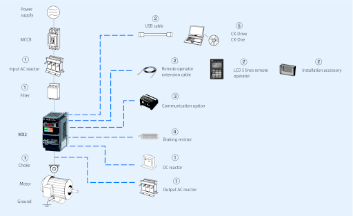
3G3MX2
|
Specifications |
Order code |
||||||
|---|---|---|---|---|---|---|---|
|
Voltage class |
Constant torque |
Variable torque |
Standard (IP20) |
Finless |
IP54 |
||
|
Max motor kW |
Rated current A |
Max motor kW |
Rated current A |
||||
|
Single-phase 200 V |
0.1 |
1.0 |
0.2 |
1.2 |
3G3MX2-AB001-E |
3G3MX2-AB001-P-E |
3G3MX2-DB001-E/EC |
|
0.2 |
1.6 |
0.4 |
1.9 |
3G3MX2-AB002-E |
3G3MX2-AB002-P-E |
3G3MX2-DB002-E/EC |
|
|
0.4 |
3.0 |
0.55 |
3.5 |
3G3MX2-AB004-E |
3G3MX2-AB004-P-E |
3G3MX2-DB004-E/EC |
|
|
0.75 |
5.0 |
1.1 |
6.0 |
3G3MX2-AB007-E |
3G3MX2-AB007-P-E |
3G3MX2-DB007-EC |
|
|
1.5 |
8.0 |
2.2 |
9.6 |
3G3MX2-AB015-E |
3G3MX2-AB015-P-E |
3G3MX2-DB015-EC |
|
|
2.2 |
11.0 |
3.0 |
12.0 |
3G3MX2-AB022-E |
3G3MX2-AB022-P-E |
3G3MX2-DB022-EC |
|
|
Three-phase 200 V |
0.1 |
1.0 |
0.2 |
1.2 |
3G3MX2-A2001-E |
3G3MX2-A2001-P-E |
3G3MX2-D2001-E/EC |
|
0.2 |
1.6 |
0.4 |
1.9 |
3G3MX2-A2002-E |
3G3MX2-A2002-P-E |
3G3MX2-D2002-E/EC |
|
|
0.4 |
3.0 |
0.55 |
3.5 |
3G3MX2-A2004-E |
3G3MX2-A2004-P-E |
3G3MX2-D2004-E/EC |
|
|
0.75 |
5.0 |
1.1 |
6.0 |
3G3MX2-A2007-E |
3G3MX2-A2007-P-E |
3G3MX2-D2007-E/EC |
|
|
1.5 |
8.0 |
2.2 |
9.6 |
3G3MX2-A2015-E |
3G3MX2-A2015-P-E |
3G3MX2-D2015-EC |
|
|
2.2 |
11.0 |
3.0 |
12.0 |
3G3MX2-A2022-E |
3G3MX2-A2022-P-E |
3G3MX2-D2022-EC |
|
|
3.7 |
17.5 |
5.5 |
19.6 |
3G3MX2-A2037-E |
3G3MX2-A2037-P-E |
3G3MX2-D2037-EC |
|
|
5.5 |
25.0 |
7.5 |
30.0 |
3G3MX2-A2055-E |
— |
3G3MX2-D2055-EC |
|
|
7.5 |
33.0 |
11 |
40.0 |
3G3MX2-A2075-E |
— |
3G3MX2-D2075-EC |
|
|
11 |
47.0 |
15 |
56.0 |
3G3MX2-A2110-E |
— |
3G3MX2-D2110-EC |
|
|
15 |
60.0 |
18.5 |
69.0 |
3G3MX2-A2150-E |
— |
3G3MX2-D2150-EC |
|
|
Three-phase 400 V |
0.4 |
1.8 |
0.75 |
2.1 |
3G3MX2-A4004-E |
3G3MX2-A4004-P-E |
3G3MX2-D4004-EC |
|
0.75 |
3.4 |
1.5 |
4.1 |
3G3MX2-A4007-E |
3G3MX2-A4007-P-E |
3G3MX2-D4007-EC |
|
|
1.5 |
4.8 |
2.2 |
5.4 |
3G3MX2-A4015-E |
3G3MX2-A4015-P-E |
3G3MX2-D4015-EC |
|
|
2.2 |
5.5 |
3.0 |
6.9 |
3G3MX2-A4022-E |
3G3MX2-A4022-P-E |
3G3MX2-D4022-EC |
|
|
3.0 |
7.2 |
4.0 |
8.8 |
3G3MX2-A4030-E |
3G3MX2-A4030-P-E |
3G3MX2-D4030-EC |
|
|
4.0 |
9.2 |
5.5 |
11.1 |
3G3MX2-A4040-E |
3G3MX2-A4040-P-E |
3G3MX2-D4040-EC |
|
|
5.5 |
14.8 |
7.5 |
17.5 |
3G3MX2-A4055-E |
— |
3G3MX2-D4055-EC |
|
|
7.5 |
18.0 |
11 |
23.0 |
3G3MX2-A4075-E |
— |
3G3MX2-D4075-EC |
|
|
11 |
24.0 |
15 |
31.0 |
3G3MX2-A4110-E |
— |
3G3MX2-D4110-EC |
|
|
15 |
31.0 |
18.5 |
38.0 |
3G3MX2-A4150-E |
— |
3G3MX2-D4150-EC |
① Line filters
|
Inverter |
Standard line filter |
Low leakage line filter |
|||||||
|---|---|---|---|---|---|---|---|---|---|
|
Rasmi |
Schaffner |
Rasmi |
Schaffner |
||||||
|
Voltage |
Model 3G3MX2-_ |
Order code AX-FIM |
Current (A) |
Order code AX-FIM |
Current (A) |
Order code AX-FIM |
Current (A) |
Order code AX-FIM |
Current (A) |
|
1Phase 200 VAC |
AB001 / AB002 / AB004 |
1010-RE |
10 |
1010-SE-V1 |
8 |
1010-RE-LL |
10 |
1010-SE-LL |
10 |
|
AB007 |
1014-RE |
14 |
1014-SE-V1 |
14 |
1014-RE-LL |
14 |
1014-SE-LL |
14 |
|
|
AB015 / AB022 |
1024-RE |
24 |
1024-SE-V1 |
27 |
1024-RE-LL |
24 |
1024-SE-LL |
24 |
|
|
3Phase 200 VAC |
A2001 / A2002 / A2004 / A2007 |
2010-RE |
10 |
2010-SE-V1 |
7.8 |
2010-RE-LL |
10 |
— |
— |
|
A2015 / A2022 |
2020-RE |
20 |
2020-SE-V1 |
16 |
2020-RE-LL |
20 |
2020-SE-LL |
20 |
|
|
A2037 |
2030-RE |
30 |
2030-SE-V1 |
25 |
2030-RE-LL |
30 |
2030-SE-LL |
30 |
|
|
A2055 / A2075 |
2060-RE |
60 |
2060-SE-V1 |
50 |
2060-RE-LL |
60 |
2060-SE-LL |
50 |
|
|
A2110 |
2080-RE |
80 |
2080-SE-V1 |
70 |
2080-RE-LL |
80 |
— |
— |
|
|
A2150 |
2100-RE |
100 |
2100-SE-V1 |
75 |
2100-RE-LL |
100 |
— |
— |
|
|
3Phase 400 VAC |
A4004 / A4007 |
3005-RE |
5 |
3005-SE-V1 |
6 |
3005-RE-LL |
5 |
3005-SE-LL |
5 |
|
A4015 / A4022 / A4030 |
3010-RE |
10 |
3010-SE-V1 |
12 |
3010-RE-LL |
10 |
3010-SE-LL |
10 |
|
|
A4040 |
3014-RE |
14 |
3014-SE-V1 |
15 |
3014-RE-LL |
14 |
3014-SE-LL |
15 |
|
|
A4055 / A4075 |
3030-RE |
30 |
3030-SE-V1 |
29 |
3030-RE-LL |
30 |
3030-SE-LL |
30 |
|
|
A4110 / A4150 |
3050-RE |
50 |
3050-SE-V1 |
48 |
3050-RE-LL |
50 |
3050-SE-LL |
50 |
① Input AC reactors
|
Inverter |
AC Reactor |
|
|---|---|---|
|
Voltage |
Model 3G3MX2-_ |
Order code |
|
1-Phase 200 VAC |
AB002/AB004 |
AX-RAI02000070-DE |
|
AB007 |
AX-RAI01700140-DE |
|
|
AB015 |
AX-RAI01200200-DE |
|
|
AB022 |
AX-RAI00630240-DE |
|
|
3-Phase 200 VAC |
A2002/A2004/A2007 |
AX-RAI02800080-DE |
|
A2015/A2022/A2037 |
AX-RAI00880200-DE |
|
|
A2055/A2075 |
AX-RAI00350335-DE |
|
|
A2110/A2150 |
AX-RAI00180670-DE |
|
Inverter |
AC Reactor |
|
|---|---|---|
|
Voltage |
Model 3G3MX2-_ |
Order code |
|
3-Phase 400 VAC |
A4004/A4007/A4015 |
AX-RAI07700050-DE |
|
A4022/A4030/A4040 |
AX-RAI03500100-DE |
|
|
A4055/A4075 |
AX-RAI01300170-DE |
|
|
A4110/A4150 |
AX-RAI00740335-DE |
① DC reactors
|
200 V single-phase |
200 V three-phase |
400 V three-phase |
|||
|---|---|---|---|---|---|
|
Inverter |
Order code |
Inverter |
Order code |
Inverter |
Order code |
|
3G3MX2-AB001 |
AX-RC10700032-DE |
3G3MX2-A2001 |
AX-RC21400016-DE |
3G3MX2-A4004 |
AX-RC43000020-DE |
|
3G3MX2-AB002 |
3G3MX2-A2002 |
3G3MX2-A4007 |
AX-RC27000030-DE |
||
|
3G3MX2-AB004 |
AX-RC06750061-DE |
3G3MX2-A2004 |
AX-RC10700032-DE |
3G3MX2-A4015 |
AX-RC14000047-DE |
|
3G3MX2-AB007 |
AX-RC03510093-DE |
3G3MX2-A2007 |
AX-RC06750061-DE |
3G3MX2-A4022 |
AX-RC10100069-DE |
|
3G3MX2-AB015 |
AX-RC02510138-DE |
3G3MX2-A2015 |
AX-RC03510093-DE |
3G3MX2-A4030 |
AX-RC08250093-DE |
|
3G3MX2-AB022 |
AX-RC01600223-DE |
3G3MX2-A2022 |
AX-RC02510138-DE |
3G3MX2-A4040 |
AX-RC06400116-DE |
|
— |
3G3MX2-A2037 |
AX-RC01600223-DE |
3G3MX2-A4055 |
AX-RC04410167-DE |
|
|
3G3MX2-A2055 |
AX-RC01110309-DE |
3G3MX2-A4075 |
AX-RC03350219-DE |
||
|
3G3MX2-A2075 |
AX-RC00840437-DE |
3G3MX2-A4011 |
AX-RC02330307-DE |
||
|
3G3MX2-A2011 |
AX-RC00590614-DE |
3G3MX2-A4015 |
AX-RC01750430-DE |
||
|
3G3MX2-A2015 |
AX-RC00440859-DE |
— |
① Chokes
|
Diameter |
Description |
Order code |
|---|---|---|
|
21 |
For 2.2 KW motors or below |
AX-FER2102-RE |
|
25 |
For 15 KW motors or below |
AX-FER2515-RE |
|
50 |
For 45 KW motors or below |
AX-FER5045-RE |
① Output AC reactor
|
Inverter |
AC Reactor |
|
|---|---|---|
|
Voltage |
Model 3G3MX2-_ |
Order code |
|
200 VAC |
AB001/AB002/AB004/A2001/A2002/A2004 |
AX-RAO11500026-DE |
|
AB007/A2007 |
AX-RAO07600042-DE |
|
|
AB015/A2015 |
AX-RAO04100075-DE |
|
|
AB022/A2022 |
AX-RAO03000105-DE |
|
|
A2037 |
AX-RAO01830160-DE |
|
|
A2055 |
AX-RAO01150220-DE |
|
|
A2075 |
AX-RAO00950320-DE |
|
|
A2110 |
AX-RAO00630430-DE |
|
|
A2150 |
AX-RAO00490640-DE |
|
Inverter |
AC Reactor |
|
|---|---|---|
|
Voltage |
Model 3G3MX2-_ |
Order code |
|
400 VAC |
A4004/A4007/A4015 |
AX-RAO16300038-DE |
|
A4022 |
AX-RAO11800053-DE |
|
|
A4030/A4040 |
AX-RAO07300080-DE |
|
|
A4055 |
AX-RAO04600110-DE |
|
|
A4075 |
AX-RAO03600160-DE |
|
|
A4110 |
AX-RAO02500220-DE |
|
|
A4150 |
AX-RAO02000320-DE |
B Accessories
|
Types |
Description |
Functions |
Order code |
|---|---|---|---|
|
Digital operator |
LCD remote operator |
5 Line LCD remote operator with copy function, cable length max. 3m. |
AX-OP05-E |
|
Remote operator cable |
3 meters cable for connecting remote operator |
3G3AX-CAJOP300-EE |
|
|
LED remote operator |
LED remote operator, cable length max. 3m |
3G3AX-OP01 |
|
|
Mounting kit for LED operator |
Mounting kit for LED operator on panel |
4X-KITMINI |
|
|
Operator holder |
Holder to put the AX-OP05-E inside of the cabinet |
3G3AX-OP05-H-E |
|
|
Accessories |
PC configuration cable |
Mini USB to USB connector cable |
AX-CUSBM002-E |
③ Communication option boards
|
Description |
Functions |
Order code |
|---|---|---|
|
Profibus option card |
Used for running or stopping the inverter, setting or referencing parameters, and monitoring output frequency, output current, or similar items through communications with the host controller. |
3G3AX-MX2-PRT |
|
DeviceNet option card |
3G3AX-MX2-DRT |
|
|
EtherCAT option card |
3G3AX-MX2-ECT |
|
|
CompoNet option card |
3G3AX-MX2-CRT |
|
|
MECHATROLINK-II option card |
3G3AX-MX2-MRT |
|
|
EtherNet/IP option card |
3G3AX-MX2-EIP |
|
|
Extra input/output option board |
1 analog voltage input, 1 analog current input, 1 analog voltage output, 8 discrete logic inputs, |
3G3AX-MX2-EIO15-E |
④ Braking unit, braking resistor unit
|
Inverter |
Braking resistor unit |
|||||||||
|---|---|---|---|---|---|---|---|---|---|---|
|
Voltage |
Max. motor kW |
Inverter 3G3MX2_ |
Connectable min. resistance Ω |
Inverter mounted type |
Braking torque % |
Inverter mounted type |
Braking torque % |
|||
|
1-phase |
3-phase |
Order code |
Resist Ω |
Order code |
Resist Ω |
|||||
|
200 V |
0.12 |
B001 |
2001 |
100 |
AX-REM00K1400-IE |
400 |
200 |
AX-REM00K1400-IE |
400 |
200 |
|
0.25 |
B002 |
2002 |
180 |
180 |
||||||
|
0.55 |
B004 |
2004 |
AX-REM00K1200-IE |
200 |
180 |
AX-REM00K1200-IE |
200 |
180 |
||
|
1.1 |
B007 |
2007 |
50 |
100 |
AX-REM00K2070-IE |
70 |
200 |
|||
|
1.5 |
B015 |
2015 |
AX-REM00K2070-IE |
70 |
140 |
AX-REM00K4075-IE |
75 |
130 |
||
|
2.2 |
B022 |
2022 |
35 |
90 |
AX-REM00K4035-IE |
35 |
180 |
|||
|
4.0 |
— |
2040 |
AX-REM00K4075-IE |
75 |
50 |
AX-REM00K6035-IE |
35 |
100 |
||
|
5.5 |
— |
2055 |
20 |
AX-REM00K4035-IE |
35 |
75 |
AX-REM00K9020-IE |
20 |
150 |
|
|
7.5 |
— |
2075 |
17 |
55 |
AX-REM01K9017-IE |
17 |
110 |
|||
|
11 |
— |
2110 |
AX-REM00K6035-IE |
35 |
40 |
AX-REM02K1017-IE |
17 |
75 |
||
|
15 |
— |
2150 |
10 |
AX-REM00K9017-IE |
17 |
55 |
AX-REM03K5010-IE |
10 |
95 |
|
|
400 V |
0.55 |
— |
4004 |
180 |
AX-REM00K1400-IE |
400 |
200 |
AX-REM00K1400-IE |
400 |
200 |
|
1.1 |
— |
4007 |
200 |
200 |
||||||
|
1.5 |
— |
4015 |
AX-REM00K1200-IE |
200 |
190 |
AX-REM00K2200-IE |
200 |
190 |
||
|
2.2 |
— |
4022 |
100 |
AX-REM00K2200-IE |
200 |
130 |
AX-REM00K5120-IE |
120 |
200 |
|
|
3.0 |
— |
4030 |
AX-REM00K2120-IE |
120 |
160 |
160 |
||||
|
4.0 |
— |
4040 |
120 |
AX-REM00K6100-IE |
100 |
140 |
||||
|
5.5 |
— |
4055 |
70 |
AX-REM00K4075-IE |
75 |
140 |
AX-REM00K9070-IE |
70 |
150 |
|
|
7.5 |
— |
4075 |
100 |
AX-REM01K9070-IE |
70 |
110 |
||||
|
11 |
— |
4110 |
AX-REM00K6100-IE |
100 |
50 |
AX-REM02K1070-IE |
70 |
75 |
||
|
15 |
— |
4150 |
35 |
AX-REM00K9070-IE |
70 |
55 |
AX-REM03K5035-IE |
35 |
110 |
⑤ Computer software
|
Description |
Installation |
Order code |
|---|---|---|
|
Computer software |
Configuration and monitoring software tool |
CX-Drive |
|
Computer software |
Configuration and monitoring software tool |
CX-One |
|
Computer software |
Software tool for Energy Saving calculation |
€Saver |
Specifications
200 V class
|
Single-phase: 3G3MX2-_ |
B001 |
B002 |
B004 |
B0071 |
B015 |
B022 |
— |
— |
— |
— |
— |
||
|---|---|---|---|---|---|---|---|---|---|---|---|---|---|
|
Three-phase: 3G3MX2-_ |
2001 |
2002 |
2004 |
2007 |
2015 |
2022 |
2037 |
2055 |
2075 |
2110 |
2150 |
||
|
Motor kW2 |
For VT setting |
0.2 |
0.4 |
0.55 |
1.1 |
2.2 |
3.0 |
5.5 |
7.5 |
11 |
15 |
18.5 |
|
|
For CT setting |
0.1 |
0.2 |
0.4 |
0.75 |
1.5 |
2.2 |
3.7 |
5.5 |
7.5 |
11 |
15 |
||
|
Output |
Inverter capacity kVA |
200 VT |
0.4 |
0.6 |
1.2 |
2.0 |
3.3 |
4.1 |
6.7 |
10.3 |
13.8 |
19.3 |
23.9 |
|
200 CT |
0.2 |
0.5 |
1.0 |
1.7 |
2.7 |
3.8 |
6.0 |
8.6 |
11.4 |
16.2 |
20.7 |
||
|
240 VT |
0.4 |
0.7 |
1.4 |
2.4 |
3.9 |
4.9 |
8.1 |
12.4 |
16.6 |
23.2 |
28.6 |
||
|
240 CT |
0.3 |
0.6 |
1.2 |
2.0 |
3.3 |
4.5 |
7.2 |
10.3 |
13.7 |
19.5 |
24.9 |
||
|
Rated output current (A) at VT |
1.2 |
1.9 |
3.5 |
6.0 |
9.6 |
12.0 |
19.6 |
30.0 |
40.0 |
56.0 |
69.0 |
||
|
Rated output current (A) at CT |
1.0 |
1.6 |
3.0 |
5.0 |
8.0 |
11.0 |
17.5 |
25.0 |
33.0 |
47.0 |
60.0 |
||
|
Max. output voltage |
Proportional to input voltage: 0 … 240 V |
||||||||||||
|
Max. output frequency |
400 Hz |
||||||||||||
|
Power |
Rated input voltage and frequency |
Single-phase 200… 240 V 50/60 Hz 3-phase 200… 240 V 50/60 Hz |
|||||||||||
|
Allowable voltage fluctuation |
-15% … +10% |
||||||||||||
|
Allowable frequency fluctuation |
5% |
||||||||||||
|
Braking torque |
At short-time deceleration At capacitor feedback |
100%: <50Hz 50%: <60Hz |
70%: <50Hz 50%: <60Hz |
Approx 20% |
— |
||||||||
|
Cooling method |
Self cooling3 |
Forced-air-cooling |
400 V class
|
Three-phase: 3G3MX2-_ |
4004 |
4007 |
4015 |
4022 |
4030 |
4040 |
4055 |
4075 |
4110 |
4150 |
||
|---|---|---|---|---|---|---|---|---|---|---|---|---|
|
Motor kW4 |
For VT setting |
0.75 |
1.5 |
2.2 |
3.0 |
4.0 |
5.5 |
7.5 |
11 |
15 |
18.5 |
|
|
For CT setting |
0.4 |
0.75 |
1.5 |
2.2 |
3.0 |
4.0 |
5.5 |
7.5 |
11 |
15 |
||
|
Output |
Inverter capacity kVA |
380 VT |
1.3 |
2.6 |
3.5 |
4.5 |
5.7 |
7.3 |
11.5 |
15.1 |
20.4 |
25.0 |
|
380 CT |
1.1 |
2.2 |
3.1 |
3.6 |
4.7 |
6.0 |
9.7 |
11.8 |
15.7 |
20.4 |
||
|
480 VT |
1.7 |
3.4 |
4.4 |
5.7 |
7.3 |
9.2 |
14.5 |
19.1 |
25.7 |
31.5 |
||
|
480 CT |
1.4 |
2.8 |
3.9 |
4.5 |
5.9 |
7.6 |
12.3 |
14.9 |
19.9 |
25.7 |
||
|
Rated output current (A) at VT |
2.1 |
4.1 |
5.4 |
6.9 |
8.8 |
11.1 |
17.5 |
23.0 |
31.0 |
38.0 |
||
|
Rated output current (A) at CT |
1.8 |
3.4 |
4.8 |
5.5 |
7.2 |
9.2 |
14.8 |
18.0 |
24.0 |
31.0 |
||
|
Max. output voltage |
Proportional to input voltage: 0 … 480 V |
|||||||||||
|
Max. output frequency |
400 Hz |
|||||||||||
|
Power |
Rated input voltage and frequency |
3-phase 380 … 480 V 50/60 Hz |
||||||||||
|
Allowable voltage fluctuation |
-15% … +10% |
|||||||||||
|
Allowable frequency fluctuation |
5% |
|||||||||||
|
Braking torque |
At short-time deceleration2 At capacitor feedback |
100%: <50Hz 50%: <60Hz |
70%: <50Hz 50%: <60Hz |
— |
||||||||
|
Cooling method |
Self cooling5 |
Forced-air-cooling |
Dimensions
Standard models (IP20)
|
Voltage class |
Inverter model |
Dimensions in mm |
Weight (kg) |
|||
|---|---|---|---|---|---|---|
|
H |
W |
D |
||||
|
Single-phase 200 V |
3G3MX2-AB001-E |
128 |
68 |
109 |
1.0 |
|
|
3G3MX2-AB002-E |
1.0 |
|||||
|
3G3MX2-AB004-E |
122.5 |
1.1 |
||||
|
3G3MX2-AB007-E |
128 |
108 |
170.5 |
1.4 |
||
|
3G3MX2-AB015-E |
1.8 |
|||||
|
3G3MX2-AB022-E |
1.8 |
|||||
|
Three-phase 200 V |
3G3MX2-A2001-E |
128 |
68 |
109 |
1.0 |
|
|
3G3MX2-A2002-E |
1.0 |
|||||
|
3G3MX2-A2004-E |
122.5 |
1.1 |
||||
|
3G3MX2-A2007-E |
145.5 |
1.2 |
||||
|
3G3MX2-A2015-E |
128 |
108 |
170.5 |
1.6 |
||
|
3G3MX2-A2022-E |
1.8 |
|||||
|
3G3MX2-A2037-E |
128 |
140 |
170.5 |
2.0 |
||
|
3G3MX2-A2055-E |
260 |
140 |
155 |
3.0 |
||
|
3G3MX2-A2075-E |
3.4 |
|||||
|
3G3MX2-A2110-E |
296 |
180 |
175 |
5.1 |
||
|
3G3MX2-A2150-E |
350 |
220 |
175 |
7.4 |
||
|
Three-phase 400 V |
3G3MX2-A4004-E |
128 |
108 |
143.5 |
1.5 |
|
|
3G3MX2-A4007-E |
170.5 |
1.6 |
||||
|
3G3MX2-A4015-E |
1.8 |
|||||
|
3G3MX2-A4022-E |
1.9 |
|||||
|
3G3MX2-A4030-E |
1.9 |
|||||
|
3G3MX2-A4040-E |
128 |
140 |
170.5 |
2.1 |
||
|
3G3MX2-A4055-E |
260 |
155 |
3.5 |
|||
|
3G3MX2-A4075-E |
3.5 |
|||||
|
3G3MX2-A4110-E |
296 |
180 |
175 |
4.7 |
||
|
3G3MX2-A4150-E |
5.2 |

Finless models
|
Voltage class |
Inverter model |
Dimensions in mm |
Weight (kg) |
|||
|---|---|---|---|---|---|---|
|
H |
W |
D |
||||
|
Single-phase 200 V |
3G3MX2-AB001-P-E |
128 |
68 |
103 |
1.1 |
|
|
3G3MX2-AB002-P-E |
||||||
|
3G3MX2-AB004-P-E |
||||||
|
3G3MX2-AB007-P-E |
128 |
108 |
123 |
1.8 |
||
|
3G3MX2-AB015-P-E |
||||||
|
3G3MX2-AB022-P-E |
||||||
|
Three-phase 200 V |
3G3MX2-A2001-P-E |
128 |
68 |
103 |
1.1 |
|
|
3G3MX2-A2002-P-E |
||||||
|
3G3MX2-A2004-P-E |
||||||
|
3G3MX2-A2007-P-E |
||||||
|
3G3MX2-A2015-P-E |
128 |
108 |
123 |
1.8 |
||
|
3G3MX2-A2022-P-E |
||||||
|
3G3MX2-A2037-P-E |
128 |
140 |
123 |
2.1 |
||
|
Three-phase 400 V |
3G3MX2-A4004-P-E |
128 |
108 |
123 |
1.8 |
|
|
3G3MX2-A4007-P-E |
||||||
|
3G3MX2-A4015-P-E |
||||||
|
3G3MX2-A4022-P-E |
||||||
|
3G3MX2-A4030-P-E |
||||||
|
3G3MX2-A4040-P-E |
128 |
140 |
123 |
2.1 |

IP54 models
|
Voltage class |
Inverter model |
Dimensions in mm |
Weight (kg) |
|||
|---|---|---|---|---|---|---|
|
H |
W |
D |
||||
|
Single-phase 200 V |
3G3MX2-DB001-E |
464.74 |
179.5 |
292.7 |
8.0 |
|
|
3G3MX2-DB001-EC |
482.8 |
309.5 |
317.7 |
11.8 |
||
|
3G3MX2-DB002-E |
464.74 |
179.5 |
292.7 |
8.0 |
||
|
3G3MX2-DB002-EC |
482.8 |
309.5 |
317.7 |
11.8 |
||
|
3G3MX2-DB004-E |
464.74 |
179.5 |
292.7 |
8.4 |
||
|
3G3MX2-DB004-EC |
482.8 |
309.5 |
317.7 |
12.1 |
||
|
3G3MX2-DB007-EC |
12.4 |
|||||
|
3G3MX2-DB015-EC |
16.0 |
|||||
|
3G3MX2-DB022-EC |
16.0 |
|||||
|
Three-phase 200 V |
3G3MX2-D2001-E |
464.74 |
179.5 |
292.7 |
8.0 |
|
|
3G3MX2-D2001-EC |
482.8 |
309.5 |
317.7 |
11.8 |
||
|
3G3MX2-D2002-E |
464.74 |
179.5 |
292.7 |
8.0 |
||
|
3G3MX2-D2002-EC |
482.8 |
309.5 |
317.7 |
11.8 |
||
|
3G3MX2-D2004-E |
464.74 |
179.5 |
292.7 |
8.1 |
||
|
3G3MX2-D2004-EC |
482.8 |
309.5 |
317.7 |
11.9 |
||
|
3G3MX2-D2007-E |
464.74 |
179.5 |
292.7 |
8.2 |
||
|
3G3MX2-D2007-EC |
482.8 |
309.5 |
317.7 |
12.0 |
||
|
3G3MX2-D2015-EC |
15.4 |
|||||
|
3G3MX2-D2022-EC |
15.6 |
|||||
|
3G3MX2-D2037-EC |
16.2 |
|||||
|
3G3MX2-D2055-EC |
627.04 |
325 |
299.5 |
18.8 |
||
|
3G3MX2-D2075-EC |
19.2 |
|||||
|
3G3MX2-D2110-EC |
710.35 |
379 |
329.7 |
25.3 |
||
|
3G3MX2-D2150-EC |
28.0 |
|||||
|
Three-phase 400 V |
3G3MX2-D4004-EC |
482.8 |
309.5 |
317.7 |
12.0 |
|
|
3G3MX2-D4007-EC |
12.5 |
|||||
|
3G3MX2-D4015-EC |
12.4 |
|||||
|
3G3MX2-D4022-EC |
12.5 |
|||||
|
3G3MX2-D4030-EC |
12.5 |
|||||
|
3G3MX2-D4040-EC |
13.1 |
|||||
|
3G3MX2-D4055-EC |
627.04 |
325 |
299.5 |
18.7 |
||
|
3G3MX2-D4075-EC |
18.7 |
|||||
|
3G3MX2-D4110-EC |
710.35 |
379 |
329.7 |
23.8 |
||
|
3G3MX2-D4150-EC |
24.3 |

CX-Drive

Сэкономьте свое время и упростите конфигурирование, пуско-наладку и обслуживание инверторов и сервоприводов, используя единый программный инструмент. CX-Drive поддерживает особенности новых серий сервоприводов Accurax G5 и инвертора MX2.
CX-One

CX-One — это объединенный комплект программного обеспечения с единым лицензионным номером. Установив однажды CX-One, пользователь сможет создавать, конфигурировать и программировать множество различных устройств, таких как ПЛК, ЧМИ или системы многоосного управления перемещениями, а также сети. CX-One значительно упрощает работу инженера и сводит к минимуму необходимость обучения программированию или конфигурированию систем автоматизации.
Контроллер насоса

Богатые возможности программирования новых инверторов RX и MX2 обеспечивают решение наиболее сложных задач.
Устройства намотки/размотки

Решение для инверторов содержит специальные прикладные функции, такие как расчет диаметра без датчика, двусторонние режимы намотки/размотки и управление натяжением с помощью крутящего момента или ПИД-регулятора.
Техническая поддержка

Несмотря на большой объем технической информации, доступной на нашем сайте, мы создали еще специальны раздел, чтобы предоставить вам еще больше сведений и оказать техническую поддержку.