Thank you for choosing this SMARTSTEP A-series product. Proper use and handling
of the product will ensure proper product performance, will lengthen product life, and
may prevent possible accidents.
Please read this manual thoroughly and handle and operate the product with care.
Please keep this manual handy for reference after reading it.
1. To ensure safe and proper use of the OMRON Inverters, please read this USER’S MANUAL (Cat. No.
I533-E1) to gain sufficient knowledge of the devices, safety information, and precautions before actual
use.
2. The products are illustrated without covers and shieldings for closer look in this USER’S MANUAL. For
actual use of the products, make sure to use the covers and shieldings as specified.
3. This USER’S MANUAL and other related user’s manuals are to be delivered to the actual end users of the
products.
4. Please keep this manual close at hand for future reference.
5. If the product has been left unused for a long time, please inquire at our sales representative.
1. This manual describes information about installation, wiring, switch setting, and troubleshooting of the
SMARTSTEP A-series Servomotors and Servo Drivers. For information about actual operating proce-
dures using a Parameter Unit, refer to the SMARTSTEP A Series Operation Manual (I534).
2. Be sure that this manual accompanies the product to its final user.
3. Although care has been given in documenting the product, please contact your OMRON representative
if you have any suggestions on improving this manual.
4. Assume that anything not specifically described in this manual is not possible.
5. Do not allow the Servomotor or Servo Driver to be wired, set, or operated (from a Parameter Unit) by
anyone that is not a profession electrical engineer or the equivalent.
6. We recommend that you add the following precautions to any instruction manuals you prepare for the
system into which the product is being installed.
• Precautions on the dangers of high-voltage equipment.
• Precautions on touching the terminals of the product even after power has been turned OFF. (These
terminals are live even with the power turned OFF.)
7. Specifications and functions may be changed without notice in order to improve product performance.
8. Positive and negative rotation of AC Servomotors described in this manual are defined as looking at the
end of the output shaft of the motor as follows: Counterclockwise rotation is positive and clockwise rota-
tion is negative.
9. Do not perform withstand-voltage or other megameter tests on the product. Doing so may damage inter-
nal components.
10. Servomotors and Servo Drivers have a finite service life. Be sure to keep replacement products on hand
and to consider the operating environment and other conditions affecting the service life.
11. Do not set values for any parameters not described in this manual. Operating errors may result. Consult
your OMRON representative if you have questions.
12. Before using the product under conditions which are not described in the manual or applying the product
to nuclear control systems, railroad systems, aviation systems, vehicles, combustion systems, medical
equipment, amusement machines, safety equipment, and other systems, machines, and equipment that
may have a serious influence on lives and property if used improperly, consult your OMRON represen-
tative.
Items to Check Before Unpacking
1. Check the following items before removing the product from the package:
• Has the correct product been delivered (i.e., the correct model number and specifications)?
• Has the product been damaged in shipping?
2. Check that the following accessories have been delivered.
• Safety Precautions
No connectors or mounting screws are provided. Obtain these separately.
NOTICE
![]()
Cat. No. I533-E1-04
SMARTSTEP A SERIES
R7M-A@ (Servomotors)
R7D-AP@ (Servo Drivers)
Servomotors/Servo Drivers
USER’S MANUAL

Thank you for choosing this SMARTSTEP A-series product. Proper use and handling of the product will ensure proper product performance, will lengthen product life, and may prevent possible accidents.
Please read this manual thoroughly and handle and operate the product with care. Please keep this manual handy for reference after reading it.
1.To ensure safe and proper use of the OMRON Inverters, please read this USER’S MANUAL (Cat. No. I533-E1) to gain sufficient knowledge of the devices, safety information, and precautions before actual use.
2.The products are illustrated without covers and shieldings for closer look in this USER’S MANUAL. For actual use of the products, make sure to use the covers and shieldings as specified.
3.This USER’S MANUAL and other related user’s manuals are to be delivered to the actual end users of the products.
4.Please keep this manual close at hand for future reference.
5.If the product has been left unused for a long time, please inquire at our sales representative.
NOTICE
1.This manual describes information about installation, wiring, switch setting, and troubleshooting of the SMARTSTEP A-series Servomotors and Servo Drivers. For information about actual operating procedures using a Parameter Unit, refer to the SMARTSTEP A Series Operation Manual (I534).
2.Be sure that this manual accompanies the product to its final user.
3.Although care has been given in documenting the product, please contact your OMRON representative if you have any suggestions on improving this manual.
4.Assume that anything not specifically described in this manual is not possible.
5.Do not allow the Servomotor or Servo Driver to be wired, set, or operated (from a Parameter Unit) by anyone that is not a profession electrical engineer or the equivalent.
6.We recommend that you add the following precautions to any instruction manuals you prepare for the system into which the product is being installed.
•Precautions on the dangers of high-voltage equipment.
•Precautions on touching the terminals of the product even after power has been turned OFF. (These terminals are live even with the power turned OFF.)
7.Specifications and functions may be changed without notice in order to improve product performance.
8.Positive and negative rotation of AC Servomotors described in this manual are defined as looking at the end of the output shaft of the motor as follows: Counterclockwise rotation is positive and clockwise rotation is negative.
9.Do not perform withstand-voltage or other megameter tests on the product. Doing so may damage internal components.
10.Servomotors and Servo Drivers have a finite service life. Be sure to keep replacement products on hand and to consider the operating environment and other conditions affecting the service life.
11.Do not set values for any parameters not described in this manual. Operating errors may result. Consult your OMRON representative if you have questions.
12.Before using the product under conditions which are not described in the manual or applying the product to nuclear control systems, railroad systems, aviation systems, vehicles, combustion systems, medical equipment, amusement machines, safety equipment, and other systems, machines, and equipment that may have a serious influence on lives and property if used improperly, consult your OMRON representative.
Items to Check Before Unpacking
1.Check the following items before removing the product from the package:
•Has the correct product been delivered (i.e., the correct model number and specifications)?
•Has the product been damaged in shipping?
2.Check that the following accessories have been delivered.
•Safety Precautions
No connectors or mounting screws are provided. Obtain these separately.

USER’S MANUAL
SMARTSTEP ASERIES
MODELS R7M-A@ (Servomotors)
R7D-AP@ (Servo Drivers)
Servomotors/Servo Drivers
Notice:
OMRON products are manufactured for use according to proper procedures by a qualified operator and only for the purposes described in this manual.
The following conventions are used to indicate and classify precautions in this manual. Always heed the information provided with them. Failure to heed precautions can result in injury to people or damage to property.
!DANGER Indicates an imminently hazardous situation which, if not avoided, will result in death or serious injury. Additionally, there may be severe property damage.
!WARNING Indicates a potentially hazardous situation which, if not avoided, could result in death or serious injury. Additionally, there may be severe property damage.
!Caution Indicates a potentially hazardous situation which, if not avoided, may result in minor or moderate injury, or property damage.
OMRON Product References
All OMRON products are capitalized in this manual. The word “Unit” is also capitalized when it refers to an OMRON product, regardless of whether or not it appears in the proper name of the product.
The abbreviation “Ch,” which appears in some displays and on some OMRON products, often means “word” and is abbreviated “Wd” in documentation in this sense.
The abbreviation “PC” means Programmable Controller and is not used as an abbreviation for anything else.
Visual Aids
The following headings appear in the left column of the manual to help you locate different types of information.
Note Indicates information of particular interest for efficient and convenient operation of the product.
OMRON, 2001
All rights reserved. No part of this publication may be reproduced, stored in a retrieval system, or transmitted, in any form, or by any means, mechanical, electronic, photocopying, recording, or otherwise, without the prior written permission of OMRON.
No patent liability is assumed with respect to the use of the information contained herein. Moreover, because OMRON is constantly striving to improve its high-quality products, the information contained in this manual is subject to change without notice. Every precaution has been taken in the preparation of this manual. Nevertheless, OMRON assumes no responsibility for errors or omissions. Neither is any liability assumed for damages resulting from the use of the information contained in this publication.
General Warnings
Observe the following warnings when using the SMARTSTEP Servomotor and Servo Driver and all connected or peripheral devices.
This manual may include illustrations of the product with protective covers removed in order to describe the components of the product in detail. Make sure that these protective covers are on the product before use.
Consult your OMRON representative when using the product after a long period of storage.
!WARNING Always connect the frame ground terminals of the Servo Driver and the Servomotor to a class-3 ground (to 100 Ω or less). Not connecting to a class-3 ground may result in electric shock.
!WARNING Do not touch the inside of the Servo Driver. Doing so may result in electric shock.
!WARNING Do not remove the front cover, terminal covers, cables, or optional items while the power is being supplied. Doing so may result in electric shock.
!WARNING Installation, operation, maintenance, or inspection must be performed by authorized personnel. Not doing so may result in electric shock or injury.
!WARNING Wiring or inspection must not be performed for at least five minutes after turning OFF the power supply. Doing so may result in electric shock.
!WARNING Do not damage, press, or put excessive stress or heavy objects on the cables. Doing so may result in electric shock.
!WARNING Do not touch the rotating parts of the Servomotor in operation. Doing so may result in injury.
!WARNING Do not modify the product. Doing so may result in injury or damage to the product.
!WARNING Provide a stopping mechanism on the machine to ensure safety. The holding brake is not designed as a stopping mechanism for safety purposes.
!WARNING Provide an external emergency stopping mechanism that can stop operation and shutting off the power supply immediately. Not doing so may result in injury.
!WARNING Do not come close to the machine immediately after resetting momentary power interruption to avoid an unexpected restart. (Take appropriate measures to secure safety against an unexpected restart.) Doing so may result in injury.
!Caution Use the Servomotors and Servo Drivers in a specified combination. Using them incorrectly may result in fire or damage to the products.
!Caution Do not store or install the product in the following places. Doing so may result in fire, electric shock, or damage to the product.
•Locations subject to direct sunlight.
•Locations subject to temperatures or humidity outside the range specified in the specifications.
•Locations subject to condensation as the result of severe changes in temperature.
•Locations subject to corrosive or flammable gases.
•Locations subject to dust (especially iron dust) or salts.
•Locations subject to shock or vibration.
•Locations subject to exposure to water, oil, or chemicals.
!Caution Do not touch the Servo Driver radiator, Servo Driver regeneration resistor, or Servomotor while the power is being supplied or soon after the power is turned OFF. Doing so may result in a skin burn due to the hot surface.
Storage and Transportation Precautions
!Caution Do not hold the product by the cables or motor shaft while transporting it. Doing so may result in injury or malfunction.
!Caution Do not place any load exceeding the figure indicated on the product. Doing so may result in injury or malfunction.
Installation and Wiring Precautions
!Caution Do not step on or place a heavy object on the product. Doing so may result in injury.
!Caution Do not cover the inlet or outlet ports and prevent any foreign objects from entering the product. Doing so may result in fire.
!Caution Be sure to install the product in the correct direction. Not doing so may result in malfunction.
!Caution Provide the specified clearances between the Servo Driver and the control panel or with other devices. Not doing so may result in fire or malfunction.
!Caution Do not apply any strong impact. Doing so may result in malfunction.
!Caution Be sure to wire correctly and securely. Not doing so may result in motor runaway, injury, or malfunction.
!Caution Be sure that all the mounting screws, terminal screws, and cable connector screws are tightened to the torque specified in the relevant manuals. Incorrect tightening torque may result in malfunction.
!Caution Use crimp terminals for wiring. Do not connect bare stranded wires directly to terminals. Connection of bare stranded wires may result in burning.
!Caution Always use the power supply voltage specified in the User’s Manual. An incorrect voltage may result in malfunction or burning.
!Caution Take appropriate measures to ensure that the specified power with the rated voltage and frequency is supplied. Be particularly careful in places where the power supply is unstable. An incorrect power supply may result in malfunction.
!Caution Install external breakers and take other safety measures against short-circuiting in external wiring. Insufficient safety measures against short-circuiting may result in burning.
!Caution Take appropriate and sufficient countermeasures when installing systems in the following locations. Failure to do so may result in damage to the product.
•Locations subject to static electricity or other forms of noise.
•Locations subject to strong electromagnetic fields and magnetic fields.
•Locations subject to possible exposure to radioactivity.
•Locations close to power supplies.
Operation and Adjustment Precautions
!Caution Confirm that no adverse effects will occur in the system before performing the test operation. Not doing so may result in equipment damage.
!Caution Check the newly set parameters and switches for proper execution before actually running them. Not doing so may result in equipment damage.
!Caution Do not make any extreme adjustments or setting changes. Doing so may result in unstable operation and injury.
!Caution Separate the Servomotor from the machine, check for proper operation, and then connect to the machine. Not doing so may cause injury.
!Caution When an alarm occurs, remove the cause, reset the alarm after confirming safety, and then resume operation. Not doing so may result in injury.
!Caution Do not use the built-in brake of the Servomotor for ordinary braking. Doing so may result in malfunction.
Maintenance and Inspection Precautions
!WARNING Do not attempt to disassemble, repair, or modify any Units. Any attempt to do so may result in malfunction, fire, or electric shock.
!Caution Resume operation only after transferring to the new Unit the contents of the data required for operation. Not doing so may result in an unexpected operation.
![]()
Warning Labels
Warning labels are pasted on the product as shown in the following illustration. Be sure to follow the instructions given there.
Warning label
Example from R7D-AP01L
Example from R7D-AP01L

Read and Understand this Manual
Please read and understand this manual before using the product. Please consult your OMRON representative if you have any questions or comments.
Warranty and Limitations of Liability
WARRANTY
OMRON’s exclusive warranty is that the products are free from defects in materials and workmanship for a period of one year (or other period if specified) from date of sale by OMRON.
OMRON MAKES NO WARRANTY OR REPRESENTATION, EXPRESS OR IMPLIED, REGARDING NONINFRINGEMENT, MERCHANTABILITY, OR FITNESS FOR PARTICULAR PURPOSE OF THE PRODUCTS. ANY BUYER OR USER ACKNOWLEDGES THAT THE BUYER OR USER ALONE HAS DETERMINED THAT THE PRODUCTS WILL SUITABLY MEET THE REQUIREMENTS OF THEIR INTENDED USE. OMRON DISCLAIMS ALL OTHER WARRANTIES, EXPRESS OR IMPLIED.
LIMITATIONS OF LIABILITY
OMRON SHALL NOT BE RESPONSIBLE FOR SPECIAL, INDIRECT, OR CONSEQUENTIAL DAMAGES, LOSS OF PROFITS OR COMMERCIAL LOSS IN ANY WAY CONNECTED WITH THE PRODUCTS, WHETHER SUCH CLAIM IS BASED ON CONTRACT, WARRANTY, NEGLIGENCE, OR STRICT LIABILITY.
In no event shall the responsibility of OMRON for any act exceed the individual price of the product on which liability is asserted.
IN NO EVENT SHALL OMRON BE RESPONSIBLE FOR WARRANTY, REPAIR, OR OTHER CLAIMS REGARDING THE PRODUCTS UNLESS OMRON’S ANALYSIS CONFIRMS THAT THE PRODUCTS WERE PROPERLY HANDLED, STORED, INSTALLED, AND MAINTAINED AND NOT SUBJECT TO CONTAMINATION, ABUSE, MISUSE, OR INAPPROPRIATE MODIFICATION OR REPAIR.

Application Considerations
SUITABILITY FOR USE
OMRON shall not be responsible for conformity with any standards, codes, or regulations that apply to the combination of products in the customer’s application or use of the products.
At the customer’s request, OMRON will provide applicable third party certification documents identifying ratings and limitations of use that apply to the products. This information by itself is not sufficient for a complete determination of the suitability of the products in combination with the end product, machine, system, or other application or use.
The following are some examples of applications for which particular attention must be given. This is not intended to be an exhaustive list of all possible uses of the products, nor is it intended to imply that the uses listed may be suitable for the products:
•Outdoor use, uses involving potential chemical contamination or electrical interference, or conditions or uses not described in this manual.
•Nuclear energy control systems, combustion systems, railroad systems, aviation systems, medical equipment, amusement machines, vehicles, safety equipment, and installations subject to separate industry or government regulations.
•Systems, machines, and equipment that could present a risk to life or property.
Please know and observe all prohibitions of use applicable to the products.
NEVER USE THE PRODUCTS FOR AN APPLICATION INVOLVING SERIOUS RISK TO LIFE OR PROPERTY WITHOUT ENSURING THAT THE SYSTEM AS A WHOLE HAS BEEN DESIGNED TO ADDRESS THE RISKS, AND THAT THE OMRON PRODUCTS ARE PROPERLY RATED AND INSTALLED FOR THE INTENDED USE WITHIN THE OVERALL EQUIPMENT OR SYSTEM.
PROGRAMMABLE PRODUCTS
OMRON shall not be responsible for the user’s programming of a programmable product, or any consequence thereof.

Disclaimers
CHANGE IN SPECIFICATIONS
Product specifications and accessories may be changed at any time based on improvements and other reasons.
It is our practice to change model numbers when published ratings or features are changed, or when significant construction changes are made. However, some specifications of the products may be changed without any notice. When in doubt, special model numbers may be assigned to fix or establish key specifications for your application on your request. Please consult with your OMRON representative at any time to confirm actual specifications of purchased products.
DIMENSIONS AND WEIGHTS
Dimensions and weights are nominal and are not to be used for manufacturing purposes, even when tolerances are shown.
PERFORMANCE DATA
Performance data given in this manual is provided as a guide for the user in determining suitability and does not constitute a warranty. It may represent the result of OMRON’s test conditions, and the users must correlate it to actual application requirements. Actual performance is subject to the OMRON Warranty and Limitations of Liability.
ERRORS AND OMISSIONS
The information in this manual has been carefully checked and is believed to be accurate; however, no responsibility is assumed for clerical, typographical, or proofreading errors, or omissions.
|
Table of Contents |
|||||
|
Chapter 1. Introduction. . . . . . . . . . . . . . . . . . . . . . . . . . . . . . . . . . . . |
1-1 |
||||
|
1-1 |
Features. . . . . . . . . . . . . . . . . . . . . . . . . . . . . . . . . . . . . . . . . . . . . . . . . . . . . . . . . . . . . . . . . . |
1-2 |
|||
|
1-2 |
System Configuration . . . . . . . . . . . . . . . . . . . . . . . . . . . . . . . . . . . . . . . . . . . . . . . . . . . . . . . |
1-4 |
|||
|
1-3 |
Servo Driver Nomenclature . . . . . . . . . . . . . . . . . . . . . . . . . . . . . . . . . . . . . . . . . . . . . . . . . . |
1-5 |
|||
|
1-4 |
Applicable Standards . . . . . . . . . . . . . . . . . . . . . . . . . . . . . . . . . . . . . . . . . . . . . . . . . . . . . . . |
1-6 |
|||
|
1-5 |
System Block Diagrams . . . . . . . . . . . . . . . . . . . . . . . . . . . . . . . . . . . . . . . . . . . . . . . . . . . . . |
1-7 |
|||
|
Chapter 2. Standard Models and Specifications. . . . . . . . . . . . . . . . |
2-1 |
||||
|
2-1 |
Standard Models. . . . . . . . . . . . . . . . . . . . . . . . . . . . . . . . . . . . . . . . . . . . . . . . . . . . . . . . . . . |
2-2 |
|||
|
2-2 |
External and Mounted Dimensions . . . . . . . . . . . . . . . . . . . . . . . . . . . . . . . . . . . . . . . . . . . . |
2-6 |
|||
|
2-3 |
Servo Driver Specifications . . . . . . . . . . . . . . . . . . . . . . . . . . . . . . . . . . . . . . . . . . . . . . . . . . |
2-17 |
|||
|
2-4 |
Servomotor Specifications . . . . . . . . . . . . . . . . . . . . . . . . . . . . . . . . . . . . . . . . . . . . . . . . . . . |
2-31 |
|||
|
2-5 |
Reduction Gear Specifications . . . . . . . . . . . . . . . . . . . . . . . . . . . . . . . . . . . . . . . . . . . . . . . . |
2-39 |
|||
|
2-6 |
Cable and Connector Specifications. . . . . . . . . . . . . . . . . . . . . . . . . . . . . . . . . . . . . . . . . . . . |
2-43 |
|||
|
2-7 |
Servo Relay Units and Cable Specifications . . . . . . . . . . . . . . . . . . . . . . . . . . . . . . . . . . . . . |
2-58 |
|||
|
2-8 |
Parameter Unit Specifications . . . . . . . . . . . . . . . . . . . . . . . . . . . . . . . . . . . . . . . . . . . . . . . . |
2-111 |
|||
|
2-9 |
External Regeneration Resistor Specifications. . . . . . . . . . . . . . . . . . . . . . . . . . . . . . . . . . . . |
2-113 |
|||
|
2-10 |
DC Reactors . . . . . . . . . . . . . . . . . . . . . . . . . . . . . . . . . . . . . . . . . . . . . . . . . . . . . . . . . . . . . . |
2-114 |
|||
|
Chapter 3. System Design and Installation . . . . . . . . . . . . . . . . . . . . |
3-1 |
||||
|
3-1 |
Installation Conditions . . . . . . . . . . . . . . . . . . . . . . . . . . . . . . . . . . . . . . . . . . . . . . . . . . . . . . |
3-3 |
|||
|
3-2 |
Wiring. . . . . . . . . . . . . . . . . . . . . . . . . . . . . . . . . . . . . . . . . . . . . . . . . . . . . . . . . . . . . . . . . . . |
3-8 |
|||
|
3-3 |
Regenerative Energy Absorption . . . . . . . . . . . . . . . . . . . . . . . . . . . . . . . . . . . . . . . . . . . . . . |
3-37 |
|||
|
Chapter 4. Operation. . . . . . . . . . . . . . . . . . . . . . . . . . . . . . . . . . . . . . |
4-1 |
||||
|
4-1 |
Operational Procedure . . . . . . . . . . . . . . . . . . . . . . . . . . . . . . . . . . . . . . . . . . . . . . . . . . . . . . |
4-3 |
|||
|
4-2 |
Switch Settings . . . . . . . . . . . . . . . . . . . . . . . . . . . . . . . . . . . . . . . . . . . . . . . . . . . . . . . . . . . . |
4-4 |
|||
|
4-3 |
Preparing for Operation . . . . . . . . . . . . . . . . . . . . . . . . . . . . . . . . . . . . . . . . . . . . . . . . . . . . . |
4-7 |
|||
|
4-4 |
Trial Operation . . . . . . . . . . . . . . . . . . . . . . . . . . . . . . . . . . . . . . . . . . . . . . . . . . . . . . . . . . . . |
4-9 |
|||
|
4-5 |
Gain Adjustments . . . . . . . . . . . . . . . . . . . . . . . . . . . . . . . . . . . . . . . . . . . . . . . . . . . . . . . . . . |
4-11 |
|||
|
4-6 |
User Parameters . . . . . . . . . . . . . . . . . . . . . . . . . . . . . . . . . . . . . . . . . . . . . . . . . . . . . . . . . . . |
4-15 |
|||
|
4-7 |
Operating Functions . . . . . . . . . . . . . . . . . . . . . . . . . . . . . . . . . . . . . . . . . . . . . . . . . . . . . . . . |
4-26 |
|||
|
Chapter 5. Troubleshooting . . . . . . . . . . . . . . . . . . . . . . . . . . . . . . . . |
5-1 |
||||
|
5-1 |
Measures when Trouble Occurs . . . . . . . . . . . . . . . . . . . . . . . . . . . . . . . . . . . . . . . . . . . . . . . |
5-2 |
|||
|
5-2 |
Alarms . . . . . . . . . . . . . . . . . . . . . . . . . . . . . . . . . . . . . . . . . . . . . . . . . . . . . . . . . . . . . . . . . . |
5-5 |
|||
|
5-3 |
Troubleshooting . . . . . . . . . . . . . . . . . . . . . . . . . . . . . . . . . . . . . . . . . . . . . . . . . . . . . . . . . . . |
5-7 |
|||
|
5-4 |
Overload Characteristics (Electron Thermal Characteristics) . . . . . . . . . . . . . . . . . . . . . . . . |
5-15 |
|||
|
5-5 |
Periodic Maintenance . . . . . . . . . . . . . . . . . . . . . . . . . . . . . . . . . . . . . . . . . . . . . . . . . . . . . . . |
5-16 |
|||
|
Chapter 6. Appendix . . . . . . . . . . . . . . . . . . . . . . . . . . . . . . . . . . . . . . |
6-1 |
||||
|
6-1 |
Connection Examples. . . . . . . . . . . . . . . . . . . . . . . . . . . . . . . . . . . . . . . . . . . . . . . . . . . . . . . |
6-2 |
|||
|
Revision History. . . . . . . . . . . . . . . . . . . . . . . . . . . . . . . . . . . . . . . . . . |
R-1 |
||||

Chapter 1
Introduction
1-1 Features
1-2 System Configuration
1-3 Servo Driver Nomenclature
1-4 Applicable Standards
1-5 System Block Diagrams

1-1 Features
The SMARTSTEP A-series Servomotors and Servo Drivers have been developed as pulse string input-type Position Controllers to replace stepping motors in simple positioning systems. The SMARTSTEP A-series Servomotors and Servo Drivers combine the stepping motor’s ease of use with faster positioning resulting from high speed and high torque, higher reliability with no loss of positioning accuracy even during sudden load changes, and other advanced features.
■ Faster Response and Rotation Speed
SMARTSTEP A-series Servomotors and Servo Drivers incorporate the same high-speed and hightorque features, unachievable with stepping motors, as the OMNUC W Series. The SMARTSTEP A- series Servomotors provide faster rotation speeds of up to 4,500 r/min, with constant operation possible at this speed. Faster output torque of up to 1 s can output up to approximately 300% of the rated torque, providing even faster middleand long-stroke positioning.
■ Constant Accuracy
The A-series product line’s higher encoder resolution of 2,000 pulses/rotation provides feedback control enabling continuous operation without loss of positioning accuracy, even with sudden load changes or sudden acceleration or deceleration.
■ Minimal Setting with Servo Driver Front Panel Switches
The SMARTSTEP A Series can be operated immediately without time-consuming parameter setting. The A-series Servo Drivers’ front panel switches enable easier alteration of function or positioning resolution settings.
● Resolution Settings
SMARTSTEP A-series Servomotor resolution can be selected from the following four levels: 500 pulses/rotation (0.72°/step); 1,000 pulses/rotation (0.36°/step) (default setting); 5,000 pulses/ rotation (0.072°/step); or 10,000 pulses/rotation (0.036°/step)
● Command Pulse Input Setting
SMARTSTEP A-series command pulse input setting can be switched between CW/CCW (2-pulse) and SIGN/PULS (single-pulse) methods to easily adapt to Position Controller output specifications.
● Dynamic Brake Setting
SMARTSTEP A-series Servomotors can be forcibly decelerated to a stop at RUN OFF or when an alarm occurs.
● Gain Setting
A special rotary switch on SMARSTEP A-series Servo Drivers enables easy gain setting. Online autotuning can also be activated with the flick of a switch, and responsiveness can be easily matched to the machinery to be used.
1-2
Note Using a Parameter Unit or personal computer enables operation with parameter settings.
■ Cylinder-style and Flat-style Servomotors
The SMARTSTEP A Series offers Flanged Cylinder-style Servomotors, with a smaller mounting area, and Flat-style Servomotors, with a shorter overall length. The Flat Servomotor depth dimensions are approximately the same as those of stepping motors of the same output capacity. Servomotors can be selected by size, thereby making equipment more compact.
■ A Wider Selection of Programming Devices
Special SMARTSTEP A-series Parameter Units and personal computer monitoring software are available. The special monitoring software enables performing parameter setting, speed and current monitoring, speed and current waveform displays, I/O monitoring, autotuning, jogging, and other operations from a computer. It is also possible to perform multiple-axis communications that set the parameters and monitor operations for multiple Servo Drivers. For details, refer to the Servo Driver Personal Computer Monitor Software (CD-ROM) for Windows 95/98, Version 2.0 (WMON Win Ver.2.0) (Catalog No.: SBCE-011).
1-3

1-2 System Configuration
|
SYSMAC + Position Control Unit with pulse string output |
||||
|
B.B INP |
TGON |
REF POWER |
||
|
VCMP |
||||
|
NC413 |
||||
|
MACHINE |
||||
|
No. |
||||
|
CN1 CN2 |
||||
|
R7A–PR02A PARAMETER UNIT |
||||
|
RESET |
SCROLL |
MODE/SET |
||
|
Pulse String |
||||
|
SYSMAC CJ/CS/C/CV |
Position Control Units |
JOG |
DATA |
|
|
RUN |
||||
|
Programmable Controller |
CJ1W-NC113/213/413 |
|||
|
CJ1W-NC133/233/433 |
READ |
WRITE |
||
|
CS1W-NC113/213/413 |
DRIVER |
PR PR |
DRIVER |
|
|
CS1W-NC133/233/433 |
R7A-PR02A Parameter Unit |
|||
|
C200HW-NC113/213/413 |
(Hand-held) |
|||
|
C500-NC113/211 |
||||
|
SYSMAC Programmable Controllers with pulse outputs |
|
SYSMAC CPM2A |
SYSMAC CPM2C |
PA203
POWER

 /
/

SYSMAC CQM1H
Single-shaft Positioner with pulse string output
|
MS |
OP |
EN |
|||
|
NS |
No. |
OPEN |
|||
|
13F88M- |
LINE |
||||
|
M0 |
DRT141 |
LINE |
|||
|
AXIS |
CW |
||||
|
M1 |
POSITIONER |
CCW |
|
M2 |
ALARM |
||||||||||
|
2 |
34 |
NA |
M2 |
LS |
IT |
||||||
|
9 |
M1 |
FT LIM |
|||||||||
|
78 |
×10 |
M0 |
SO SRH NG |
||||||||
|
ORG |
R ALM |
||||||||||
|
2 |
34 |
CODE |
|||||||||
|
9 |
EN |
STOP M |
|||||||||
|
87 |
×1 |
DRIVE |
R AL |
||||||||
|
R |
|||||||||||
|
1 |
DR0 |
OTHE |
|||||||||
|
2 ON |
|||||||||||
|
3 ↓ |
DR1 |
N |
|||||||||
|
L/R |
ED : |
) |
MUNICATIO |
||||||||
|
(R |
COM |
||||||||||
|
H |
SPEEDbps |
||||||||||
|
DIP SW |
ITC |
125k |
|||||||||
|
DR1 |
250kbps |
||||||||||
|
DR0 |
O |
FF |
|||||||||
|
F |
500kbps |
||||||||||
|
OFF |
OF |
− |
|||||||||
|
ON |
LOCAL/REMOTE |
||||||||||
|
ON |
ON |
||||||||||
|
OFF |
H |
MODE |
|||||||||
|
ON |
ITC |
REMOTEL |
MODE |
||||||||
|
P SW |
|||||||||||
|
DI |
L/R |
LOCA |
|||||||||
|
OFF |
|||||||||||
|
ON |
I/O
3F88M-DRT141 Single-shaft Positioner for DeviceNet
SMARTSTEP A-series
R7D-AP@ Servo Driver
SMARTSTEP A-series
R7M-A@ Servomotor
1-4
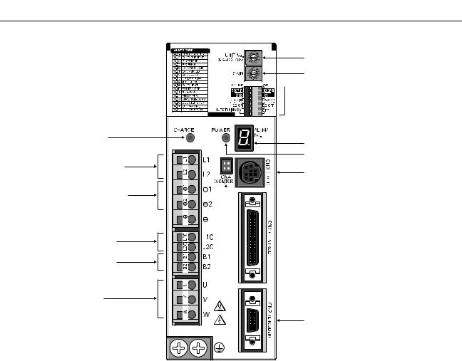
1-3 Servo Driver Nomenclature
|
Main-circuit power supply |
|
indicator |
|
Main-circuit power |
|
supply input terminals |
|
DC reactor connection terminals |
|
Control-circuit power supply |
|
input terminals |
|
External regeneration |
|
resistance terminals |
|
Servomotor power terminals |
FG terminals for power supply and  servomotor power
Rotary switch for unit No. selection
Rotary switch for gain adjustment

 Function selection switches:
• Switch/parameter setting enable switch
• Resolution setting
• Command pulse input setting
•Dynamic braking setting
•Online autotuning switch
Alarm display
Control-circuit power supply indicator
Communications connector (CN3)

 Monitor output connector (CN4)

 Control I/O connector (CN1)
Encoder input connector (CN2)
1-5

|
Introduction |
Chapter 1 |
||
1-4 Applicable Standards |
|||
|
■ EC Directives |
|||
|
EC Directives |
Product |
Applicable standards |
Remarks |
|
Low Voltage |
AC Servo Drivers |
EN50178 |
Safety requirements for electrical |
|
Directive |
devices for measurement, control, |
||
|
and research facilities |
|||
|
AC Servomotors |
IEC60034-1, -5, -8, -9 |
Rotating electrical equipment |
|
|
EN60034-1, -9 |
|||
|
EMC Directives |
AC Servo Drivers and |
EN55011 class A group 1 |
Wireless interference and measure- |
|
AC Servomotors |
ment methods for radio-frequency |
||
|
devices for industry, science, and |
|||
|
medical application |
|||
|
EN61000-6-2 |
Electromagnetic compatibility and |
||
|
immunity standards for industrial |
|||
|
environments |
|||
Note Installation under the conditions stipulated in 3-2-5 EMC-compatible Wiring must be met to ensure conformance to EMC Directives.
■ UL and cUL Standards
|
Standards |
Product |
Applicable standards |
File No. |
Remarks |
||
|
UL |
AC Servo Drivers |
UL508C |
E179149 |
Power conversion devices |
||
|
AC Servomotors |
UL1004 |
E179189 |
Electric motors |
|||
|
cUL |
AC Servo Drivers |
cUL C22.2 |
No. 14 |
E179149 |
Industrial control devices |
|
|
AC Servomotors |
cUL C22.2 |
No. 100 |
E179189 |
Motors and generators |
||
1-6
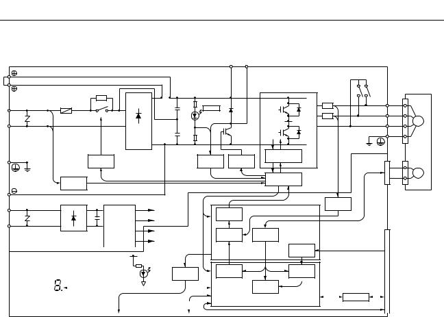
1-5 System Block Diagrams
■ 100 V AC: R7D-APA3L/-APA5L/-AP01L/-AP02L/-AP04L
|
AC Servo Driver |
||||||||||||
|
1 |
B1 |
B2 |
||||||||||
|
2 |
AC Servomotor |
|||||||||||
|
Fuse |
P1 |
P2 |
U |
U |
||||||||
|
R |
CHARGE |
|||||||||||
|
V |
||||||||||||
|
L1 |
V |
|||||||||||
|
W |
M |
|||||||||||
|
T |
W |
|||||||||||
|
L2 |
+ |
(See note.) |
||||||||||
|
− |
N2 |
|||||||||||
|
N1 |
||||||||||||
|
Relay |
Voltage |
Gate drive |
||||||||||
|
overcurrent protection |
CN2 |
|||||||||||
|
drive |
detection |
Gate drive |
||||||||||
|
Interface |
E |
|||||||||||
|
Voltage |
||||||||||||
|
detection |
||||||||||||
|
L1C |
Current |
|||||||||||
|
+ |
+ |
±5 V |
PWM |
ASIC |
detection |
|||||||
|
− |
− |
DC/DC |
+16.5 V |
generation |
||||||||
|
L2C |
conversion |
+5 V |
Digital |
Encoder signal |
CN1 |
|||||||
|
±15 V |
current amp |
processing |
||||||||||
|
Command |
||||||||||||||||||||||
|
+5 V |
pulse |
Command |
||||||||||||||||||||
|
processing |
pulse input |
|||||||||||||||||||||
|
POWER |
Analog |
Current |
Position |
|||||||||||||||||||
|
command |
||||||||||||||||||||||
|
voltage |
processing |
control |
||||||||||||||||||||
|
0 V |
conversion |
Speed |
||||||||||||||||||||
|
Serial port |
control |
I/O |
Control I/O |
|||||||||||||||||||
|
Alarm code display |
CPU |
|||||||||||||||||||||
|
RS-422 |
||||||||||||||||||||||
|
CN4 |
CN3 |
Note |
Only on R7D-AP04H/AP04L. |
|||||||||||||||||||
|
Analog monitor output |
Parameter Unit/computer |
1-7

■ 200 V AC: R7D-APA3H/-APA5H/-AP01H/-AP02H/-AP04H
|
AC Servo Driver |
||||||
|
1 |
B1 |
B2 |
||||
|
2 |
P1 |
AC Servomotor |
||||
|
Fuse |
P2 |
U |
U |
|||
|
CHARGE |
||||||
|
R |
V |
|||||
|
+ |
V |
|||||
|
L1 |
W |
M |
||||
|
T |
− |
W |
||||
|
L2 |
(See note.) |
N2
N1
|
Relay |
Voltage |
Gate drive |
|
|
Gate drive |
overcurrent protection |
||
|
drive |
detection |
CN2 |
|
Interface |
E |
||||||||
|
Voltage |
|||||||||
|
detection |
|||||||||
|
L1C |
Current |
||||||||
|
+ |
±5 V |
PWM |
ASIC |
detection |
|||||
|
+ |
|||||||||
|
− |
DC/DC |
+16.5 V |
generation |
||||||
|
− |
|||||||||
|
L2C |
conversion |
+5 V |
Digital |
Encoder signal |
CN1 |
||||
|
±15 V |
current amp |
processing |
|||||||
|
Command |
||||||||||||||||||||||
|
+5 V |
pulse |
Command |
||||||||||||||||||||
|
processing |
pulse input |
|||||||||||||||||||||
|
POWER |
Analog |
Current |
Position |
|||||||||||||||||||
|
command |
||||||||||||||||||||||
|
voltage |
processing |
control |
||||||||||||||||||||
|
0 V |
conversion |
|||||||||||||||||||||
|
Speed |
||||||||||||||||||||||
|
Serial port |
control |
I/O |
Control I/O |
|||||||||||||||||||
|
Alarm code display |
CPU |
|||||||||||||||||||||
|
RS-422 |
||||||||||||||||||||||
|
CN4 |
CN3 |
Note |
Only on R7D-AP04H/AP04L. |
|||||||||||||||||||
|
Analog monitor output |
Parameter Unit/computer |
■ 200 V AC: R7D-AP08H
AC Servo Driver
|
1 |
B1 B2 B3 |
FAN |
|
±12 V |
||
|
2 |
AC Servomotor |
|
|
P |
P |
U |
U |
||||||
|
R |
Fuse |
CHARGE |
|||||||
|
V |
|||||||||
|
L1 |
+ |
V |
|||||||
|
W |
M |
||||||||
|
S |
− |
W |
|||||||
|
L2 |
|||||||||
|
L3 |
T |
N |
N |
||||||
|
Relay |
Voltage |
Gate |
Gate drive over- |
||||||
|
current protection |
CN2 |
||||||||
|
drive |
detection |
drive |
Ther- |
||||||
|
mistor |
E |
||||||||
|
Voltage |
Interface |
||||||||
|
detection |
|
L1C |
Current |
|||||||||||||||||||||||||||||||
|
ASIC |
detection |
|||||||||||||||||||||||||||||||
|
+ |
±5 V |
PWM |
||||||||||||||||||||||||||||||
|
+ |
||||||||||||||||||||||||||||||||
|
− |
− |
DC/DC |
+16.5 V |
generation |
||||||||||||||||||||||||||||
|
conversion |
CN1 |
|||||||||||||||||||||||||||||||
|
L2C |
+5 V |
Digital |
Encoder |
|||||||||||||||||||||||||||||
|
current amp |
signal |
|||||||||||||||||||||||||||||||
|
±15 V |
processing |
|||||||||||||||||||||||||||||||
|
Command |
Command |
|||||||||||||||||||||||||||||||
|
pulse |
||||||||||||||||||||||||||||||||
|
+5 V |
processing |
pulse input |
||||||||||||||||||||||||||||||
|
Position |
||||||||||||||||||||||||||||||||
|
POWER |
Analog |
Current |
||||||||||||||||||||||||||||||
|
command |
||||||||||||||||||||||||||||||||
|
voltage |
control |
|||||||||||||||||||||||||||||||
|
processing |
||||||||||||||||||||||||||||||||
|
0 V |
conversion |
|||||||||||||||||||||||||||||||
|
Speed |
||||||||||||||||||||||||||||||||
|
Serial port |
control |
I/O |
Control I/O |
|||||||||||||||||||||||||||||
|
Alarm code display |
CPU |
|||||||||||||||||||||||||||||||
|
RS-422 |
||||||||||||||||||||||||||||||||
|
CN4 |
CN3 |
|||||||||||||||||||||||||||||||
|
Analog monitor output |
Parameter Unit/computer |
1-8

Chapter 2
Standard Models and
Specifications
2-1 Standard Models
2-2 External and Mounted Dimensions
2-3 Servo Driver Specifications
2-4 Servomotor Specifications
2-5 Reduction Gear Specifications
2-6 Cable and Connector Specifications
2-7 Servo Relay Units and Cable Specifications
2-8 Parameter Unit Specifications
2-9 External Regeneration Resistor Specifications
2-10 DC Reactors

|
Standard Models and Specifications |
Chapter 2 |
|
2-1 Standard Models
■ Servomotors
● 3,000-r/min Cylinder-style Servomotors
|
Specifications |
Model |
|||
|
Without |
Straight shaft |
30 W |
R7M-A03030 |
|
|
brake |
without key |
|||
|
50 W |
R7M-A05030 |
|||
|
100 W |
R7M-A10030 |
|||
|
200 W |
R7M-A20030 |
|||
|
400 W |
R7M-A40030 |
|||
|
750 W |
R7M-A75030 |
|||
|
Straight shaft |
30 W |
R7M-A03030-S1 |
||
|
with key |
||||
|
50 W |
R7M-A05030-S1 |
|||
|
100 W |
R7M-A10030-S1 |
|||
|
200 W |
R7M-A20030-S1 |
|||
|
400 W |
R7M-A40030-S1 |
|||
|
750 W |
R7M-A75030-S1 |
|||
|
With |
Straight shaft |
30 W |
R7M-A03030-B |
|
|
brake |
without key |
|||
|
50 W |
R7M-A05030-B |
|||
|
100 W |
R7M-A10030-B |
|||
|
200 W |
R7M-A20030-B |
|||
|
400 W |
R7M-A40030-B |
|||
|
750 W |
R7M-A75030-B |
|||
|
Straight shaft |
30 W |
R7M-A03030-BS1 |
||
|
with key |
||||
|
50 W |
R7M-A05030-BS1 |
|||
|
100 W |
R7M-A10030-BS1 |
|||
|
200 W |
R7M-A20030-BS1 |
|||
|
400 W |
R7M-A40030-BS1 |
|||
|
750 W |
R7M-A75030-BS1 |
|||
● 3,000-r/min Flat-style Servomotors
|
Specifications |
Model |
|||
|
Without |
Straight shaft |
100 W |
R7M-AP10030 |
|
|
brake |
without key |
|||
|
200 W |
R7M-AP20030 |
|||
|
400 W |
R7M-AP40030 |
|||
|
750 W |
R7M-AP75030 |
|||
|
Straight shaft |
100 W |
R7M-AP10030-S1 |
||
|
with key |
||||
|
200 W |
R7M-AP20030-S1 |
|||
|
400 W |
R7M-AP40030-S1 |
|||
|
750 W |
R7M-AP75030-S1 |
|||
|
With |
Straight shaft |
100 W |
R7M-AP10030-B |
|
|
brake |
without key |
|||
|
200 W |
R7M-AP20030-B |
|||
|
400 W |
R7M-AP40030-B |
|||
|
750 W |
R7M-AP75030-B |
|||
|
Straight shaft |
100 W |
R7M-AP10030-BS1 |
||
|
with key |
||||
|
200 W |
R7M-AP20030-BS1 |
|||
|
400 W |
R7M-AP40030-BS1 |
|||
|
750 W |
R7M-AP75030-BS1 |
■ Servo Drivers
|
Specifications |
Model |
||
|
Single-phase |
30 W |
R7D-APA3L |
|
|
100 V AC |
|||
|
50 W |
R7D-APA5L |
||
|
100 W |
R7D-AP01L |
||
|
200 W |
R7D-AP02L |
||
|
400 W |
R7D-AP04L |
||
|
Single-phase |
30 W |
R7D-APA3H |
|
|
200 V AC |
|||
|
50 W |
R7D-APA5H |
||
|
100 W |
R7D-AP01H |
||
|
200 W |
R7D-AP02H |
||
|
400 W |
R7D-AP04H |
||
|
750 W |
R7D-AP08H |
||
2-2
|
Standard Models and Specifications |
Chapter 2 |
■ Reduction Gears (Straight Shaft with Key)
●For Cylinder-style Servomotors (Backlash = 3′ Max.)
|
Specifications |
Model |
|
|
Servomotor |
Reduction gears |
|
|
capacity |
(deceleration ratio) |
|
|
50 W |
1/5 |
R7G-VRSFPB05B50 |
|
1/9 |
R7G-VRSFPB09B50 |
|
|
1/15 |
R7G-VRSFPB15B50 |
|
|
1/25 |
R7G-VRSFPB25B50 |
|
|
100 W |
1/5 |
R7G-VRSFPB05B100 |
|
1/9 |
R7G-VRSFPB09B100 |
|
|
1/15 |
R7G-VRSFPB15B100 |
|
|
1/25 |
R7G-VRSFPB25B100 |
|
|
200 W |
1/5 |
R7G-VRSFPB05B200 |
|
1/9 |
R7G-VRSFPB09C400 |
|
|
1/15 |
R7G-VRSFPB15C400 |
|
|
1/25 |
R7G-VRSFPB25C200 |
|
|
400 W |
1/5 |
R7G-VRSFPB05C400 |
|
1/9 |
R7G-VRSFPB09C400 |
|
|
1/15 |
R7G-VRSFPB15C400 |
|
|
1/25 |
R7G-VRSFPB25D400 |
|
|
750 W |
1/5 |
R7G-VRSFPB05C750 |
|
1/9 |
R7G-VRSFPB09D750 |
|
|
1/15 |
R7G-VRSFPB15D750 |
|
|
1/25 |
R7G-VRSFPB25E750 |
|
Note There are no reduction gears for 30-W Servomotors.
●For Cylinder-style Servomotors (Backlash = 45′ Max.)
|
Specifications |
Model |
|
|
Servomotor |
Reduction gears |
|
|
capacity |
(deceleration ratio) |
|
|
50 W |
1/5 |
R7G-RGSF05B50 |
|
1/9 |
R7G-RGSF09B50 |
|
|
1/15 |
R7G-RGSF15B50 |
|
|
1/25 |
R7G-RGSF25B50 |
|
|
100 W |
1/5 |
R7G-RGSF05B100 |
|
1/9 |
R7G-RGSF09B100 |
|
|
1/15 |
R7G-RGSF15B100 |
|
|
1/25 |
R7G-RGSF25B100 |
|
|
200 W |
1/5 |
R7G-RGSF05B200 |
|
1/9 |
R7G-RGSF09C400 |
|
|
1/15 |
R7G-RGSF15C400 |
|
|
1/25 |
R7G-RGSF25C400 |
|
|
400 W |
1/5 |
R7G-RGSF05C400 |
|
1/9 |
R7G-RGSF09C400 |
|
|
1/15 |
R7G-RGSF15C400 |
|
|
1/25 |
R7G-RGSF25C400 |
|
|
750 W |
1/5 |
R7G-RGSF05C750 |
|
1/9 |
R7G-RGSF09C750 |
|
|
1/15 |
R7G-RGSF15C750 |
|
|
1/25 |
R7G-RGSF25C750 |
|
Note There are no reduction gears for 30-W Servomotors.
●For Flat-style Servomotors (Backlash = 3′ Max.)
|
Specifications |
Model |
|
|
Servomotor |
Reduction gears |
|
|
capacity |
(deceleration ratio) |
|
|
100 W |
1/5 |
R7G-VRSFPB05B100P |
|
1/9 |
R7G-VRSFPB09B100P |
|
|
1/15 |
R7G-VRSFPB15B100P |
|
|
1/25 |
R7G-VRSFPB25C100P |
|
|
200 W |
1/5 |
R7G-VRSFPB05B200P |
|
1/9 |
R7G-VRSFPB09C400P |
|
|
1/15 |
R7G-VRSFPB15C400P |
|
|
1/25 |
R7G-VRSFPB25C200P |
|
|
400 W |
1/5 |
R7G-VRSFPB05C400P |
|
1/9 |
R7G-VRSFPB09C400P |
|
|
1/15 |
R7G-VRSFPB15C400P |
|
|
1/25 |
R7G-VRSFPB25D400P |
|
|
750 W |
1/5 |
R7G-VRSFPB05C750P |
|
1/9 |
R7G-VRSFPB09D750P |
|
|
1/15 |
R7G-VRSFPB15D750P |
|
|
1/25 |
R7G-VRSFPB25E750P |
|
●For Flat-style Servomotors (Backlash = 45′ Max.)
|
Specifications |
Model |
|
|
Servomotor |
Reduction gears |
|
|
capacity |
(deceleration ratio) |
|
|
100 W |
1/5 |
R7G-RGSF05B100P |
|
1/9 |
R7G-RGSF09B100P |
|
|
1/15 |
R7G-RGSF15B100P |
|
|
1/25 |
R7G-RGSF25B100P |
|
|
200 W |
1/5 |
R7G-RGSF05B200P |
|
1/9 |
R7G-RGSF09C400P |
|
|
1/15 |
R7G-RGSF15C400P |
|
|
1/25 |
R7G-RGSF25C400P |
|
|
400 W |
1/5 |
R7G-RGSF05C400P |
|
1/9 |
R7G-RGSF09C400P |
|
|
1/15 |
R7G-RGSF15C400P |
|
|
1/25 |
R7G-RGSF25C400P |
|
|
750 W |
1/5 |
R7G-RGSF05C750P |
|
1/9 |
R7G-RGSF09C750P |
|
|
1/15 |
R7G-RGSF15C750P |
|
|
1/25 |
R7G-RGSF25C750P |
|
2-3
|
Standard Models and Specifications |
Chapter 2 |
■ Servo Relay Units for CN1
|
Specifications |
Model |
|||
|
Servo |
For CS1W-NC113/133 |
XW2B-20J6-1B |
||
|
Relay Unit |
CJ1W-NC113/133 |
|||
|
C200HW-NC113 |
||||
|
C200H-NC112 |
||||
|
3F88M-DRT141 |
||||
|
(No communications supported.) |
||||
|
For CS1W-NC213/233/413/433 |
XW2B-40J6-2B |
|||
|
CJ1W-NC213/233/413/433 |
||||
|
C200HW-NC213/413 |
||||
|
C500-NC113/211 |
||||
|
C200H-NC211 |
||||
|
(No communications supported.) |
||||
|
For CS1W-HCP22 |
XW2B-20J6-3B |
|||
|
CQM1H-PLB21 |
||||
|
CQM1-CPU43-V1 |
||||
|
(No communications supported.) |
||||
|
For CS1W-NC213/233/413/433 |
XW2B-40J6-4A |
|||
|
CJ1W-NC213/233/413/433 |
||||
|
(Communications supported.) |
||||
|
For CJ1M-CPU21/CPU22/ |
XW2B-20J6-8A |
|||
|
CPU23 |
||||
|
XW2B-40J6-9A |
||||
|
For CS1W-HCP22-V1 and |
XW2B-80J7-1A |
|||
|
FQM1-MMP21 |
||||
|
Servo |
No communications |
1 m |
XW2Z-100J-B5 |
|
|
Driver |
supported. |
|||
|
2 m |
XW2Z-200J-B5 |
|||
|
Cable |
||||
|
Communications sup- |
1 m |
XW2Z-100J-B7 |
||
|
ported. |
||||
|
2 m |
XW2Z-200J-B7 |
|||
|
For FQM1-MMP21 |
1 m |
XW2Z-100J-B10 |
||
|
2 m |
XW2Z-200J-B10 |
|||
|
For CS1W-HCP22-V1 |
1 m |
XW2Z-100J-B12 |
||
|
2 m |
XW2Z-200J-B12 |
|||
|
Position |
For CQM1H-PLB21, |
0.5 m |
XW2Z-050J-A3 |
|
|
Control |
CQM1-CPU43-V1 |
|||
|
1 m |
XW2Z-100J-A3 |
|||
|
Unit Cable |
||||
|
For C200H-NC112 |
0.5 m |
XW2Z-050J-A4 |
||
|
1 m |
XW2Z-100J-A4 |
|||
|
For C200H-NC211, |
0.5 m |
XW2Z-050J-A5 |
||
|
C500-NC113/211 |
||||
|
1 m |
XW2Z-100J-A5 |
|||
|
For CS1W-NC113, |
0.5 m |
XW2Z-050J-A8 |
||
|
C200HW-NC113 |
||||
|
1 m |
XW2Z-100J-A8 |
|||
|
For CS1W-NC213/413, |
0.5 m |
XW2Z-050J-A9 |
||
|
C200HW-NC213/413 |
||||
|
1 m |
XW2Z-100J-A9 |
|||
|
For CS1W-NC133 |
0.5 m |
XW2Z-050J-A12 |
||
|
1 m |
XW2Z-100J-A12 |
|||
|
For CS1W-NC233/433 |
0.5 m |
XW2Z-050J-A13 |
||
|
1 m |
XW2Z-100J-A13 |
|||
|
For CJ1W-NC113 |
0.5 m |
XW2Z-050J-A16 |
||
|
1 m |
XW2Z-100J-A16 |
|||
|
For CJ1W-NC213/413 |
0.5 m |
XW2Z-050J-A17 |
||
|
1 m |
XW2Z-100J-A17 |
|||
|
For CJ1W-NC133 |
0.5 m |
XW2Z-050J-A20 |
||
|
1 m |
XW2Z-100J-A20 |
|||
|
For CJ1W-NC233/433 |
0.5 m |
XW2Z-050J-A21 |
||
|
1 m |
XW2Z-100J-A21 |
|||
|
For CS1W-HCP22 |
0.5 m |
XW2Z-050J-A22 |
||
|
(1 axis) |
||||
|
1 m |
XW2Z-100J-A22 |
|||
|
For CS1W-HCP22 |
0.5 m |
XW2Z-050J-A23 |
||
|
(2 axes) |
||||
|
1 m |
XW2Z-100J-A23 |
|||
|
For 3F88M-DRT141 |
0.5 m |
XW2Z-050J-A25 |
||
|
1 m |
XW2Z-100J-A25 |
|||
|
Specifications |
Model |
|||
|
Position |
For CJ1M-CPU21/ |
1 m |
XW2Z-100J-A26 |
|
|
Control |
CPU22/CPU23 |
|||
|
Unit Cable |
||||
|
For FQM1-MMP21 for |
0.5 m |
XW2Z-050J-A28 |
||
|
general-purpose I/O |
||||
|
1 m |
XW2Z-100J-A28 |
|||
|
For CS1W-HCP22-V1 |
0.5 m |
XW2Z-050J-A29 |
||
|
for general-purpose I/O |
||||
|
1 m |
XW2Z-100J-A29 |
|||
|
For FQM1-MMP21 for |
0.5 m |
XW2Z-050J-A30 |
||
|
special I/O |
||||
|
1 m |
XW2Z-100J-A30 |
|||
|
For CS1W-HCP22-V1 |
0.5 m |
XW2Z-050J-A32 |
||
|
for special I/O |
||||
|
1 m |
XW2Z-100J-A32 |
|||
|
■ Control Cables for CN1 |
|
Specifications |
Model |
||
|
General-purpose Control Cable |
1 m |
R88A-CPU001S |
|
|
(with Connector on one end) |
|||
|
2 m |
R88A-CPU002S |
||
|
Connector Terminal Block Cable |
1 m |
R88A-CTU001N |
|
|
2 m |
R88A-CTU002N |
||
|
Connector Terminal Blocks |
XW2B-40F5-P |
||
■ Integrated Servomotor Cables
|
Specifications |
Model |
||
|
For Servomotors without |
3 m |
R7A-CEA003S |
|
|
brakes (both Cylinderand |
|||
|
5 m |
R7A-CEA005S |
||
|
Flat-style) |
|||
|
10 m |
R7A-CEA010S |
||
|
15 m |
R7A-CEA015S |
||
|
20 m |
R7A-CEA020S |
||
|
For Servomotors with |
3 m |
R7A-CEA003B |
|
|
brakes (both Cylinderand |
|||
|
5 m |
R7A-CEA005B |
||
|
Flat-style) |
|||
|
10 m |
R7A-CEA010B |
||
|
15 m |
R7A-CEA015B |
||
|
20 m |
R7A-CEA020B |
||
■ Separate Servomotor Cables
● Power Cables
|
Specifications |
Standard cable |
Robot cable |
||
|
model |
model |
|||
|
For Servo- |
3 m |
R88A-CAWA003S |
R88A-CAWA003SR |
|
|
motors with- |
||||
|
5 m |
R88A-CAWA005S |
R88A-CAWA005SR |
||
|
out brakes |
||||
|
(both Cylin- |
10 m |
R88A-CAWA010S |
R88A-CAWA010SR |
|
|
derand |
15 m |
R88A-CAWA015S |
R88A-CAWA015SR |
|
|
Flat-style) |
||||
|
20 m |
R88A-CAWA020S |
R88A-CAWA020SR |
||
|
For Servo- |
3 m |
R88A-CAWA003B |
R88A-CAWA003BR |
|
|
motors with |
||||
|
5 m |
R88A-CAWA005B |
R88A-CAWA005BR |
||
|
brakes (both |
||||
|
10 m |
R88A-CAWA010B |
R88A-CAWA010BR |
||
|
Cylinder- |
||||
|
and Flat- |
15 m |
R88A-CAWA015B |
R88A-CAWA015BR |
|
|
style) |
||||
|
20 m |
R88A-CAWA020B |
R88A-CAWA020BR |
||
● Encoder Cables
|
Specifications |
Standard cable |
Robot cable |
||
|
model |
model |
|||
|
For Servo- |
3 m |
R7A-CRA003C |
R7A-CRA003CR |
|
|
motors (Cyl- |
||||
|
5 m |
R7A-CRA005C |
R7A-CRA005CR |
||
|
inder-style or |
||||
|
Flat-style) |
10 m |
R7A-CRA010C |
R7A-CRA010CR |
|
|
15 m |
R7A-CRA015C |
R7A-CRA015CR |
||
|
20 m |
R7A-CRA020C |
R7A-CRA020CR |
||
Note Use a robot cable if cable flexibility is required.
2-4
|
Standard Models and Specifications |
Chapter 2 |
||||||||||
|
■ Peripheral Cable Connectors |
|||||||||||
|
Specifications |
Model |
||||||||||
|
Analog Monitor Cable (CN4) |
1 m |
R88A-CMW001S |
|||||||||
|
Computer Monitor Cable (CN3) |
DOS |
2 m |
R7A-CCA002P2 |
||||||||
|
PC98 |
2 m |
R7A-CCA002P3 |
|||||||||
|
Control I/O Connector (CN1) |
R88A-CNU01C |
||||||||||
|
Encoder Connector (CN2) |
R7A-CNA01R |
||||||||||
|
Encoder Connector (Servomotor end) |
R7A-CNA02R |
||||||||||
|
Communications Cable |
1 m |
XW2Z-100J-C1 |
|||||||||
|
2 m |
XW2Z-200J-C1 |
||||||||||
|
■ Parameter Units |
|||||||||||
|
Specifications |
Model |
||||||||||
|
Hand-held (with 1-m cable) |
R7A-PR02A |
||||||||||
|
■ External Regeneration Resistors |
|||||||||||
|
Specifications |
Model |
||||||||||
|
Resistor |
220 W 47 Ω |
R88A-RR22047S |
|||||||||
|
■ DC Reactors |
|||||||||||
|
Specifications |
Model |
||||||||||
|
For R7D-APA3L/APA5L/APA01L |
R88A-PX5063 |
||||||||||
|
For R7D-AP02L |
R88A-PX5062 |
||||||||||
|
For R7D-AP04L |
R88A-PX5061 |
||||||||||
|
For R7D-APA3H/APA5H/AP01H |
R88A-PX5071 |
||||||||||
|
For R7D-AP02H |
R88A-PX5070 |
||||||||||
|
For R7D-AP04H |
R88A-PX5069 |
||||||||||
|
For R7D-AP08H |
R88A-PX5061 |
||||||||||
|
■ Front-panel Brackets |
|||||||||||
|
Specifications |
Model |
||||||||||
|
For the SMARTSTEP A Series |
R88A-TK01W |
2-5

|
Standard Models and Specifications |
Chapter 2 |
|
2-2 External and Mounted Dimensions
2-2-1 Servo Drivers
■Single-phase 100 V AC: R7D-APA3L/-APA5L/-AP01L/-AP02L (30 W to 200 W) Single-phase 200 V AC: R7D-APA3H/-APA5H/-AP01H/-AP02H (30 W to 200 W)
● Wall Mounting
|
External dimensions |
Mounted dimensions |
17
● Front Panel Mounting (Using Mounting Brackets)
External dimensions
|
195 |
180 |
|||
Mounted dimensions
|
7.5 |
Two, M4 |
|
|
6 |
||
|
10 |
||
|
195 |
180±0.5 |
(168) |
(7.5)  6
6
2-6

|
Standard Models and Specifications |
Chapter 2 |
■Single-phase 100 V AC: R7D-AP04L (400 W) Single-phase 200 V AC: R7D-AP04H (400 W)
● Wall Mounting
|
External dimensions |
Mounted dimensions |
|
5.5 |
5 dia. |
5.5 |
|||
|
160 |
149.5 |
160 |
149.5±0.5 |
||
|
(5) |
5 |
(5) |
|||
|
12 |
(75) |
130 |
|||
|
75 |
17
● Front Panel Mounting (Using Mounting Brackets)
|
External dimensions |
|||
|
5 dia. |
24.5 |
||
|
7.5 |
52 |
1.5 |
2 |
|
195 |
180 |
|||
Mounted dimensions
|
7.5 |
Two, M4 |
|
|
6 |
||
|
10 |
||
|
195 |
180±0.5 |
(168) |
(7.5)  6
6
2-7

|
Standard Models and Specifications |
Chapter 2 |
■ Single-phase/Three-phase 200 V AC: R7D-AP08H (750 W)
● Wall Mounting
|
External dimensions |
Mounted dimensions |
|
5.5 |
5 dia. |
5.5 |
|
|
160 |
149.5 |
160 |
149.5±0.5 |
|
(5) |
90 |
(5) |
|
17
● Front Panel Mounting (Using Mounting Brackets)
External dimensions
|
5 dia. |
24.5 |
||||||
|
7.5 |
52 |
12.5 |
2 |
||||
|
195 |
180 |
|||||||||
|
(7.5) |
5 |
||||||
|
43.5 |
|||||||
|
42 |
22.5 |
||||||
Mounted dimensions
|
7.5 |
Two, M4 |
|
|
6 |
||
|
10 |
||
|
195 |
180±0.5 |
(168) |
(7.5)  6
6
2-8

|
Standard Models and Specifications |
Chapter 2 |
2-2-2 Parameter Unit
■ R7A-PR02A Hand-held Parameter Unit
17 0.8
|
B.B |
INP TGON REF POWER |
|
VCMP |
R7A–PR02A PARAMETER UNIT
SCROLL MODE/SET
RESET
JOG
DATA
RUN
READ WRITE
4.8 dia.
2-9

|
Standard Models and Specifications |
Chapter 2 |
2-2-3 Servomotors
■ Cylinder-style Servomotors without a Brake
● 30 W/50 W/100 W R7M-A03030(-S1)/-A05030(-S1)/-A10030(-S1)
300±30
|
19.5 |
20 |
300±30 |
21.5 |
5 |
||||
|
9.5 |
Two, 4.3 dia. |
Dimensions of shaft end with key (-S1) |
||||||
|
11 |
dia.S |
dia.30h7 |
46 |
40 |
h |
|||
|
dia. |
b |
|||||||
|
14 |
t1 |
|||||||
|
5 |
2.5 |
40 |
||||||
|
LL |
25 |
|||||||
|
Model |
Dimensions (mm) |
|||||||
|
LL |
S |
b |
h |
t1 |
||||
|
R7M-A03030-@ |
69.5 |
6h6 |
2 |
2 |
1.2 |
|||
|
R7M-A05030-@ |
77 |
6h6 |
2 |
2 |
1.2 |
|||
|
R7M-A10030-@ |
94.5 |
8h6 |
3 |
3 |
1.8 |
|||
|
■ Cylinder-style Servomotors with a Brake |
● 30 W/50 W/100 W R7M-A03030-B(S1)/-A05030-B(S1)/-A10030-B(S1)
300±30
|
6 dia. |
7 dia. |
300±30 |
|||||
|
19.5 |
27 |
21.5 |
5 |
||||
|
9.5 |
Two, 4.3 dia. |
Dimensions of shaft end with key (-BS1) |
|||||
|
11 |
dia.S |
dia.30h7 |
46 |
40 |
h |
||
|
dia. |
b |
||||||
|
14 |
t1 |
||||||
|
5 |
2.5 |
40 |
|||||
|
LL |
25 |
|
Model |
Dimensions (mm) |
||||
|
LL |
S |
b |
h |
t1 |
|
|
R7M-A03030-B@ |
101 |
6h6 |
2 |
2 |
1.2 |
|
R7M-A05030-B@ |
108.5 |
6h6 |
2 |
2 |
1.2 |
|
R7M-A10030-B@ |
135 |
8h6 |
3 |
3 |
1.8 |
2-10

|
Standard Models and Specifications |
Chapter 2 |
■ Cylinder-style Servomotors without a Brake
● 200 W/400 W/750 W R7M-A20030(-S1)/-A40030(-S1)/-A75030(-S1)
300±30
|
6 dia. |
Dimensions of output section of 750-W Servomotors |
|||||||
|
13 |
7 dia. |
|||||||
|
20 |
300±30 |
21.5 |
||||||
|
9 |
Four, Z dia. |
|||||||
|
2 |
||||||||
|
11 |
dia. |
D1 |
dia. |
Dimensions of shaft end with key (-S1) |
||||
|
S |
||||||||
|
D2dia. |
||||||||
|
C |
5 |
|||||||
|
5 |
||||||||
|
G |
3 |
C |
QK |
3 |
||||
|
LL |
LR |
|
Model |
Dimensions (mm) |
||||||||
|
LL |
LR |
C |
D1 |
D2 |
G |
Z |
S |
QK |
|
|
R7M-A20030-@ |
96.5 |
30 |
60 |
70 |
50h7 |
6 |
5.5 |
14h6 |
20 |
|
R7M-A40030-@ |
124.5 |
30 |
60 |
70 |
50h7 |
6 |
5.5 |
14h6 |
20 |
|
R7M-A75030-@ |
145 |
40 |
80 |
90 |
70h7 |
8 |
7 |
16h6 |
30 |
■ Cylinder-style Servomotors with a Brake
● 200 W/400 W/750 W R7M-A20030-B(S1)/-A40030-B(S1)/-A75030-B(S1)
300±30
|
6 dia. |
7 dia. |
|
|
13 |
27 |
300±30 |
|
21.5 |
||
|
9 |
Four, Z dia. |
|
|
11 |
dia. |
D |
1 |
dia. |
|
|
S |
|||||
|
D2 dia. |
C |
||||
|
G |
3 |
C |
|||
|
LL |
LR |
Dimensions of output section of 750-W Servomotors
2
Dimensions of shaft end with key (-BS1)
|
Model |
Dimensions (mm) |
||||||||
|
LL |
LR |
C |
D1 |
D2 |
G |
Z |
S |
QK |
|
|
R7M-A20030-B@ |
136 |
30 |
60 |
70 |
50h7 |
6 |
5.5 |
14h6 |
20 |
|
R7M-A40030-B@ |
164 |
30 |
60 |
70 |
50h7 |
6 |
5.5 |
14h6 |
20 |
|
R7M-A75030-B@ |
189.5 |
40 |
80 |
90 |
70h7 |
8 |
7 |
16h6 |
30 |
2-11

|
Standard Models and Specifications |
Chapter 2 |
■ Flat-style Servomotors without a Brake
● 100 W/200 W/400 W/750 W R7M-AP10030(-S1)/-AP20030(-S1)/-AP40030(-S1)/AP75030(-S1)
|
13 |
dia. |
|
|
7 |
||
|
300±30 |
||
|
A2 |
||
|
A1 |
A5 |
|
|
D1 |
Dimensions of shaft end with key (-S1) |
||
|
dia. |
h |
||
|
b |
|||
|
C |
|||
|
QK |
t1 |
|
Model |
Dimensions (mm) |
|||||||||||||||||
|
Basic servomotor dimensions |
With key (shaft |
Cable outlet dimensions |
||||||||||||||||
|
end dimensions) |
||||||||||||||||||
|
LL |
LR |
C |
D1 |
D2 |
F |
G |
Z |
S |
QK |
b |
h |
t1 |
A1 |
A2 |
A3 |
A4 |
A5 |
|
|
R7M-AP10030-@ |
62 |
25 |
60 |
70 |
50h7 |
3 |
6 |
5.5 |
8h6 |
14 |
3 |
3 |
1.8 |
9 |
18 |
25 |
21 |
14 |
|
R7M-AP20030-@ |
67 |
30 |
80 |
90 |
70h7 |
3 |
8 |
7 |
14h6 |
16 |
5 |
5 |
3 |
|||||
|
R7M-AP40030-@ |
87 |
|||||||||||||||||
|
R7M-AP75030-@ |
86.5 |
40 |
120 |
145 |
110h7 |
3.5 |
10 |
10 |
16h6 |
22 |
5 |
5 |
3 |
28 |
38 |
19 |
■ Flat-style Servomotors with a Brake
● 100 W/200 W/400 W/750 W R7M-AP10030-B(S1)/-AP20030-B(S1)/-AP40030-B(S1)/AP75030-B(S1)
300±30
|
6 dia. |
|
|
7 dia. |
|
|
13 |
300±30 |
|
A2 |
|
|
A1 |
A5 |
|
S dia. |
D1 |
Dimensions of shaft end with key (-BS1) |
||
|
dia. |
h |
|||
|
D2 dia. |
C |
b |
||
|
QK |
t1 |
|
Model |
Dimensions (mm) |
||||||||||||||||||
|
Basic servomotor dimensions |
With key (shaft |
Cable outlet dimensions |
|||||||||||||||||
|
end dimensions) |
|||||||||||||||||||
|
LL |
LR |
C |
D1 |
D2 |
F |
G |
Z |
S |
QK |
b |
h |
t1 |
A1 |
A2 |
A3 |
A4 |
A5 |
||
|
R7M-AP10030-B@ |
91 |
25 |
60 |
70 |
50h7 |
3 |
6 |
5.5 |
8h6 |
14 |
3 |
3 |
1.8 |
9 |
18 |
25 |
21 |
23 |
|
|
R7M-AP20030-B@ |
98.5 |
30 |
80 |
90 |
70h7 |
3 |
8 |
7 |
14h6 |
16 |
5 |
5 |
3 |
||||||
|
R7M-AP40030-B@ |
118.5 |
||||||||||||||||||
|
R7M-AP75030-B@ |
120 |
40 |
120 |
145 |
110h7 |
3.5 |
10 |
10 |
16h6 |
22 |
5 |
5 |
3 |
28 |
38 |
26 |
2-12

|
Standard Models and Specifications |
Chapter 2 |
||||||||||||||||||||||||
|
2-2-4 |
Reduction Gears |
||||||||||||||||||||||||
|
■ For Cylinder-style Servomotors (Backlash = 3′ |
Max.) |
||||||||||||||||||||||||
|
Model |
Dimensions (mm) |
Weight |
|||||||||||||||||||||||
|
(kg) |
|||||||||||||||||||||||||
|
LM |
LR |
C1 |
C2 |
D1 |
D2 |
D3 |
D4 |
E3 |
F |
G |
S |
T |
Z1 |
Z2 |
AT* |
l |
Key dimensions |
||||||||
|
QK |
b |
h |
t1 |
||||||||||||||||||||||
|
50 W |
1/5 |
R7G-VRSFPB05B50 |
67.5 |
32 |
52 |
40 |
46 |
60 |
50 |
45 |
10 |
3 |
6 |
12 |
20 |
M4 |
M5 |
M3 |
12 |
16 |
4 |
4 |
2.5 |
0.55 |
|
|
1/9 |
R7G-VRSFPB09B50 |
67.5 |
32 |
52 |
40 |
46 |
60 |
50 |
45 |
10 |
3 |
6 |
12 |
20 |
M4 |
M5 |
M3 |
12 |
16 |
4 |
4 |
2.5 |
0.55 |
||
|
1/15 |
R7G-VRSFPB15B50 |
78 |
32 |
52 |
40 |
46 |
60 |
50 |
45 |
10 |
3 |
6 |
12 |
20 |
M4 |
M5 |
M3 |
12 |
16 |
4 |
4 |
2.5 |
0.7 |
||
|
1/25 |
R7G-VRSFPB25B50 |
78 |
32 |
52 |
40 |
46 |
60 |
50 |
45 |
10 |
3 |
6 |
12 |
20 |
M4 |
M5 |
M3 |
12 |
16 |
4 |
4 |
2.5 |
0.7 |
||
|
100 W |
1/5 |
R7G-VRSFPB05B100 |
67.5 |
32 |
52 |
40 |
46 |
60 |
50 |
45 |
10 |
3 |
6 |
12 |
20 |
M4 |
M5 |
M3 |
12 |
16 |
4 |
4 |
2.5 |
0.55 |
|
|
1/9 |
R7G-VRSFPB09B100 |
67.5 |
32 |
52 |
40 |
46 |
60 |
50 |
45 |
10 |
3 |
6 |
12 |
20 |
M4 |
M5 |
M3 |
12 |
16 |
4 |
4 |
2.5 |
0.55 |
||
|
1/15 |
R7G-VRSFPB15B100 |
78 |
32 |
52 |
40 |
46 |
60 |
50 |
45 |
10 |
3 |
6 |
12 |
20 |
M4 |
M5 |
M3 |
12 |
16 |
4 |
4 |
2.5 |
0.7 |
||
|
1/25 |
R7G-VRSFPB25C100 |
92 |
50 |
78 |
40 |
46 |
90 |
70 |
62 |
17 |
3 |
6 |
19 |
30 |
M4 |
M6 |
M3 |
20 |
22 |
6 |
6 |
3.5 |
1.7 |
||
|
200 W |
1/5 |
R7G-VRSFPB05B200 |
72.5 |
32 |
52 |
60 |
70 |
60 |
50 |
45 |
10 |
3 |
10 |
12 |
20 |
M5 |
M5 |
M4 |
12 |
16 |
4 |
4 |
2.5 |
0.72 |
|
|
1/9 |
R7G-VRSFPB09C400 |
89.5 |
50 |
78 |
60 |
70 |
90 |
70 |
62 |
17 |
3 |
8 |
19 |
30 |
M5 |
M6 |
M4 |
20 |
22 |
6 |
6 |
3.5 |
1.7 |
||
|
1/15 |
R7G-VRSFPB15C400 |
100 |
50 |
78 |
60 |
70 |
90 |
70 |
62 |
17 |
3 |
8 |
19 |
30 |
M5 |
M6 |
M4 |
20 |
22 |
6 |
6 |
3.5 |
2.1 |
||
|
1/25 |
R7G-VRSFPB25C400 |
100 |
50 |
78 |
60 |
70 |
90 |
70 |
62 |
17 |
3 |
8 |
19 |
30 |
M5 |
M6 |
M4 |
20 |
22 |
6 |
6 |
3.5 |
2.1 |
||
|
400 W |
1/5 |
R7G-VRSFPB05C400 |
89.5 |
50 |
78 |
60 |
70 |
90 |
70 |
62 |
17 |
3 |
8 |
19 |
30 |
M5 |
M6 |
M4 |
20 |
22 |
6 |
6 |
3.5 |
1.7 |
|
|
1/9 |
R7G-VRSFPB09C400 |
89.5 |
50 |
78 |
60 |
70 |
90 |
70 |
62 |
17 |
3 |
8 |
19 |
30 |
M5 |
M6 |
M4 |
20 |
22 |
6 |
6 |
3.5 |
1.7 |
||
|
1/15 |
R7G-VRSFPB15C400 |
100 |
50 |
78 |
60 |
70 |
90 |
70 |
62 |
17 |
3 |
8 |
19 |
30 |
M5 |
M6 |
M4 |
20 |
22 |
6 |
6 |
3.5 |
2.1 |
||
|
1/25 |
R7G-VRSFPB25D400 |
104 |
61 |
98 |
60 |
70 |
115 |
90 |
75 |
18 |
5 |
8 |
24 |
40 |
M5 |
M8 |
M4 |
20 |
30 |
8 |
7 |
4 |
3.2 |
||
|
750 W |
1/5 |
R7G-VRSFPB05C750 |
93.5 |
50 |
78 |
80 |
90 |
90 |
70 |
62 |
17 |
3 |
10 |
19 |
30 |
M6 |
M6 |
M4 |
20 |
22 |
6 |
6 |
3.5 |
2.1 |
|
|
1/9 |
R7G-VRSFPB09D750 |
97.5 |
61 |
98 |
80 |
90 |
115 |
90 |
75 |
18 |
5 |
10 |
24 |
40 |
M6 |
M8 |
M4 |
20 |
30 |
8 |
7 |
4 |
3.4 |
||
|
1/15 |
R7G-VRSFPB15D750 |
110 |
61 |
98 |
80 |
90 |
115 |
90 |
75 |
18 |
5 |
10 |
24 |
40 |
M6 |
M8 |
M4 |
20 |
30 |
8 |
7 |
4 |
3.8 |
||
|
1/25 |
R7G-VRSFPB25E750 |
135 |
75 |
125 |
80 |
90 |
135 |
110 |
98 |
17 |
5 |
10 |
32 |
55 |
M6 |
M10 |
M4 |
20 |
45 |
10 |
8 |
5 |
7.2 |
||
* «AT» in the table refers to the set bolt.
External Diagrams
Four, Z1 dia.
Set bolt (AT)
|
E3 |
|||
|
F |
|||
|
Sh6 dia. |
D4 dia. |
D3h7 dia. |
|
|
G |
T |
||
|
LM |
LR |
Key dimensions
b
Four, Z2 dia. (effective depth: l)
2-13

|
Standard Models and Specifications |
Chapter 2 |
|||||||||||||||||||||||||
|
■ For Cylinder-style Servomotors (Backlash = 45′ Max.) |
||||||||||||||||||||||||||
|
Model |
Dimensions (mm) |
Weight |
||||||||||||||||||||||||
|
(kg) |
||||||||||||||||||||||||||
|
LM |
LR |
C1 |
C2 |
D1 |
D2 |
D3 |
D4 |
E3 |
F |
G |
S |
T |
Z1 |
Z2 |
AT* |
l |
Key dimensions |
|||||||||
|
QK |
b |
h |
t1 |
|||||||||||||||||||||||
|
50 W |
1/5 |
R7G-RGSF05B50 |
67.5 |
32 |
52 |
40 |
46 |
60 |
50 |
45 |
10 |
3 |
6 |
12 |
20 |
M4 |
M5 |
M3 |
12 |
16 |
4 |
4 |
2.5 |
0.55 |
||
|
1/9 |
R7G-RGSF09B50 |
67.5 |
32 |
52 |
40 |
46 |
60 |
50 |
45 |
10 |
3 |
6 |
12 |
20 |
M4 |
M5 |
M3 |
12 |
16 |
4 |
4 |
2.5 |
0.55 |
|||
|
1/15 |
R7G-RGSF15B50 |
78 |
32 |
52 |
40 |
46 |
60 |
50 |
45 |
10 |
3 |
6 |
12 |
20 |
M4 |
M5 |
M3 |
12 |
16 |
4 |
4 |
2.5 |
0.70 |
|||
|
1/25 |
R7G-RGSF25B50 |
78 |
32 |
52 |
40 |
46 |
60 |
50 |
45 |
10 |
3 |
6 |
12 |
20 |
M4 |
M5 |
M3 |
12 |
16 |
4 |
4 |
2.5 |
0.70 |
|||
|
100 W |
1/5 |
R7G-RGSF05B100 |
67.5 |
32 |
52 |
40 |
46 |
60 |
50 |
45 |
10 |
3 |
6 |
12 |
20 |
M4 |
M5 |
M3 |
12 |
16 |
4 |
4 |
2.5 |
0.55 |
||
|
1/9 |
R7G-RGSF09B100 |
67.5 |
32 |
52 |
40 |
46 |
60 |
50 |
45 |
10 |
3 |
6 |
12 |
20 |
M4 |
M5 |
M3 |
12 |
16 |
4 |
4 |
2.5 |
0.55 |
|||
|
1/15 |
R7G-RGSF15B100 |
78 |
32 |
52 |
40 |
46 |
60 |
50 |
45 |
10 |
3 |
6 |
12 |
20 |
M4 |
M5 |
M3 |
12 |
16 |
4 |
4 |
2.5 |
0.70 |
|||
|
1/25 |
R7G-RGSF25B100 |
78 |
32 |
52 |
40 |
46 |
60 |
50 |
45 |
10 |
3 |
6 |
12 |
20 |
M4 |
M5 |
M3 |
12 |
16 |
4 |
4 |
2.5 |
0.70 |
|||
|
200 W |
1/5 |
R7G-RGSF05B200 |
72.5 |
32 |
52 |
60 |
70 |
60 |
50 |
45 |
10 |
3 |
10 |
12 |
20 |
M5 |
M5 |
M4 |
12 |
16 |
4 |
4 |
2.5 |
0.72 |
||
|
1/9 |
R7G-RGSF09C400 |
89.5 |
50 |
78 |
60 |
70 |
90 |
70 |
62 |
17 |
3 |
8 |
19 |
30 |
M5 |
M6 |
M4 |
20 |
22 |
6 |
6 |
3.5 |
1.7 |
|||
|
1/15 |
R7G-RGSF15C400 |
100 |
50 |
78 |
60 |
70 |
90 |
70 |
62 |
17 |
3 |
8 |
19 |
30 |
M5 |
M6 |
M4 |
20 |
22 |
6 |
6 |
3.5 |
2.1 |
|||
|
1/25 |
R7G-RGSF25C400 |
100 |
50 |
78 |
60 |
70 |
90 |
70 |
62 |
17 |
3 |
8 |
19 |
30 |
M5 |
M6 |
M4 |
20 |
22 |
6 |
6 |
3.5 |
2.1 |
|||
|
400 W |
1/5 |
R7G-RGSF05C400 |
89.5 |
50 |
78 |
60 |
70 |
90 |
70 |
62 |
17 |
3 |
8 |
19 |
30 |
M5 |
M6 |
M4 |
20 |
22 |
6 |
6 |
3.5 |
1.7 |
||
|
1/9 |
R7G-RGSF09C400 |
89.5 |
50 |
78 |
60 |
70 |
90 |
70 |
62 |
17 |
3 |
8 |
19 |
30 |
M5 |
M6 |
M4 |
20 |
22 |
6 |
6 |
3.5 |
1.7 |
|||
|
1/15 |
R7G-RGSF15C400 |
100 |
50 |
78 |
60 |
70 |
90 |
70 |
62 |
17 |
3 |
8 |
19 |
30 |
M5 |
M6 |
M4 |
20 |
22 |
6 |
6 |
3.5 |
2.1 |
|||
|
1/25 |
R7G-RGSF25C400 |
100 |
50 |
78 |
60 |
70 |
90 |
70 |
62 |
17 |
3 |
8 |
19 |
30 |
M5 |
M6 |
M4 |
20 |
22 |
6 |
6 |
3.5 |
2.1 |
|||
|
750 W |
1/5 |
R7G-RGSF05C750 |
93.5 |
50 |
78 |
80 |
90 |
90 |
70 |
62 |
17 |
3 |
10 |
19 |
30 |
M6 |
M6 |
M4 |
20 |
22 |
6 |
6 |
3.5 |
2.1 |
||
|
1/9 |
R7G-RGSF09C750 |
93.5 |
50 |
78 |
80 |
90 |
90 |
70 |
62 |
17 |
3 |
10 |
19 |
30 |
M6 |
M6 |
M4 |
20 |
22 |
6 |
6 |
3.5 |
2.1 |
|||
|
1/15 |
R7G-RGSF15C750 |
110 |
50 |
78 |
80 |
90 |
90 |
70 |
62 |
17 |
3 |
10 |
19 |
30 |
M6 |
M6 |
M4 |
20 |
22 |
6 |
6 |
3.5 |
2.5 |
|||
|
1/25 |
R7G-RGSF25C750 |
110 |
50 |
78 |
80 |
90 |
90 |
70 |
62 |
17 |
3 |
10 |
19 |
30 |
M6 |
M6 |
M4 |
20 |
22 |
6 |
6 |
3.5 |
2.5 |
|||
* «AT» in the table refers to the set bolt.
External Diagrams
Four, Z1 dia.
Set bolt (AT)
|
E3 |
|||
|
F |
|||
|
Sh6 dia. |
D4 dia. |
D3h7 dia. |
|
|
G |
T |
||
|
LM |
LR |
Key dimensions
b
Four, Z2 dia. (effective depth: l)
2-14
![]()
|
Standard Models and Specifications |
Chapter 2 |
||||||||||||||||||||||||||
|
■ For Flat-style Servomotors (Backlash = 3′ |
Max.) |
||||||||||||||||||||||||||
|
Model |
Dimensions (mm) |
Weight |
|||||||||||||||||||||||||
|
(kg) |
|||||||||||||||||||||||||||
|
LM |
LR |
C1 |
C2 |
D1 |
D2 |
D3 |
D4 |
E3 |
F |
G |
S |
T |
Z1 |
Z2 |
AT* |
l |
Key dimensions |
||||||||||
|
QK |
b |
h |
t1 |
||||||||||||||||||||||||
|
100 W |
1/5 |
R7G-VRSFPB05B100P |
72.5 |
32 |
52 |
60 |
70 |
60 |
50 |
45 |
10 |
3 |
10 |
12 |
20 |
M5 |
M5 |
M4 |
12 |
16 |
4 |
4 |
2.5 |
0.72 |
|||
|
1/9 |
R7G-VRSFPB09B100P |
72.5 |
32 |
52 |
60 |
70 |
60 |
50 |
45 |
10 |
3 |
10 |
12 |
20 |
M5 |
M5 |
M4 |
12 |
16 |
4 |
4 |
2.5 |
0.72 |
||||
|
1/15 |
R7G-VRSFPB15B100P |
83 |
32 |
52 |
60 |
70 |
60 |
50 |
45 |
10 |
3 |
10 |
12 |
20 |
M5 |
M5 |
M4 |
12 |
16 |
4 |
4 |
2.5 |
0.77 |
||||
|
1/25 |
R7G-VRSFPB25C100P |
92 |
50 |
78 |
60 |
70 |
90 |
70 |
62 |
17 |
3 |
10 |
19 |
30 |
M5 |
M6 |
M3 |
20 |
22 |
6 |
6 |
3.5 |
1.8 |
||||
|
200 W |
1/5 |
R7G-VRSFPB05B200P |
72.5 |
32 |
52 |
80 |
90 |
60 |
50 |
45 |
10 |
3 |
12 |
12 |
20 |
M6 |
M5 |
M4 |
12 |
16 |
4 |
4 |
2.5 |
0.85 |
|||
|
1/9 |
R7G-VRSFPB09C400P |
93.5 |
50 |
78 |
80 |
90 |
90 |
70 |
62 |
17 |
3 |
12 |
19 |
30 |
M6 |
M6 |
M4 |
20 |
22 |
6 |
6 |
3.5 |
1.8 |
||||
|
1/15 |
R7G-VRSFPB15C400P |
100 |
50 |
78 |
80 |
90 |
90 |
70 |
62 |
17 |
3 |
12 |
19 |
30 |
M6 |
M6 |
M4 |
20 |
22 |
6 |
6 |
3.5 |
2.2 |
||||
|
1/25 |
R7G-VRSFPB25C200P |
100 |
50 |
78 |
80 |
90 |
90 |
70 |
62 |
17 |
3 |
12 |
19 |
30 |
M6 |
M6 |
M4 |
20 |
22 |
6 |
6 |
3.5 |
2.2 |
||||
|
400 W |
1/5 |
R7G-VRSFPB05C400P |
93.5 |
50 |
78 |
80 |
90 |
90 |
70 |
62 |
17 |
3 |
10 |
19 |
30 |
M6 |
M6 |
M4 |
20 |
22 |
6 |
6 |
3.5 |
1.8 |
|||
|
1/9 |
R7G-VRSFPB09C400P |
93.5 |
50 |
78 |
80 |
90 |
90 |
70 |
62 |
17 |
3 |
12 |
19 |
30 |
M6 |
M6 |
M4 |
20 |
22 |
6 |
6 |
3.5 |
1.8 |
||||
|
1/15 |
R7G-VRSFPB15C400P |
100 |
50 |
78 |
80 |
90 |
90 |
70 |
62 |
17 |
3 |
12 |
19 |
30 |
M6 |
M6 |
M4 |
20 |
22 |
6 |
6 |
3.5 |
2.2 |
||||
|
1/25 |
R7G-VRSFPB25D400P |
109 |
61 |
98 |
80 |
90 |
115 |
90 |
75 |
18 |
5 |
12 |
24 |
40 |
M6 |
M8 |
M4 |
20 |
30 |
8 |
7 |
4 |
3.4 |
||||
|
750 W |
1/5 |
R7G-VRSFPB05C750P |
98 |
50 |
78 |
120 |
145 |
90 |
70 |
62 |
17 |
3 |
15 |
19 |
30 |
M8 |
M6 |
M4 |
20 |
22 |
6 |
6 |
3.5 |
2.6 |
|||
|
1/9 |
R7G-VRSFPB09D750P |
97.5 |
61 |
98 |
120 |
145 |
115 |
90 |
75 |
18 |
5 |
15 |
24 |
40 |
M8 |
M8 |
M4 |
20 |
30 |
8 |
7 |
4 |
3.8 |
||||
|
1/15 |
R7G-VRSFPB15D750P |
110 |
61 |
98 |
120 |
145 |
115 |
90 |
75 |
18 |
5 |
15 |
24 |
40 |
M8 |
M8 |
M4 |
20 |
30 |
8 |
7 |
4 |
4.2 |
||||
|
1/25 |
R7G-VRSFPB25E750P |
155 |
75 |
125 |
120 |
145 |
135 |
110 |
98 |
17 |
5 |
15 |
32 |
55 |
M8 |
M10 |
M4 |
20 |
45 |
10 |
8 |
5 |
7.8 |
* «AT» in the table refers to the set bolt.
External Diagrams
|
E3 |
|||||
|
Four, Z1 dia. |
F |
Four, Z2 dia. |
|||
|
(effective depth: l) |
|||||
|
D1 |
dia. |
D2 |
dia. |
||
|
Sh6 dia. |
D4 dia. |
D3h7 dia. |
Set bolt (AT)
Key dimensions
b
2-15

|
Standard Models and Specifications |
Chapter 2 |
|||||||||||||||||||||||||
|
■ For Flat-style Servomotors (Backlash = 45′ Max.) |
||||||||||||||||||||||||||
|
Model |
Dimensions (mm) |
Weight |
||||||||||||||||||||||||
|
(kg) |
||||||||||||||||||||||||||
|
LM |
LR |
C1 |
C2 |
D1 |
D2 |
D3 |
D4 |
E3 |
F |
G |
S |
T |
Z1 |
Z2 |
AT* |
l |
Key dimensions |
|||||||||
|
QK |
b |
h |
t1 |
|||||||||||||||||||||||
|
100 W |
1/5 |
R7G-RGSF05B100P |
72.5 |
32 |
52 |
60 |
70 |
60 |
50 |
45 |
10 |
3 |
10 |
12 |
20 |
M5 |
M5 |
M4 |
12 |
16 |
4 |
4 |
2.5 |
0.72 |
||
|
1/9 |
R7G-RGSF09B100P |
72.5 |
32 |
52 |
60 |
70 |
60 |
50 |
45 |
10 |
3 |
10 |
12 |
20 |
M5 |
M5 |
M4 |
12 |
16 |
4 |
4 |
2.5 |
0.72 |
|||
|
1/15 |
R7G-RGSF15B100P |
78 |
32 |
52 |
60 |
70 |
60 |
50 |
45 |
10 |
3 |
8 |
12 |
20 |
M5 |
M5 |
M4 |
12 |
16 |
4 |
4 |
2.5 |
0.77 |
|||
|
1/25 |
R7G-RGSF25B100P |
78 |
32 |
52 |
60 |
70 |
60 |
50 |
45 |
10 |
3 |
8 |
12 |
20 |
M5 |
M5 |
M4 |
12 |
16 |
4 |
4 |
2.5 |
0.77 |
|||
|
200 W |
1/5 |
R7G-RGSF05B200P |
72.5 |
32 |
52 |
80 |
90 |
60 |
50 |
45 |
10 |
3 |
12 |
12 |
20 |
M6 |
M5 |
M4 |
12 |
16 |
4 |
4 |
2.5 |
0.85 |
||
|
1/9 |
R7G-RGSF09C400P |
89.5 |
50 |
78 |
80 |
90 |
90 |
70 |
62 |
17 |
3 |
12 |
19 |
30 |
M6 |
M6 |
M4 |
20 |
22 |
6 |
6 |
3.5 |
1.8 |
|||
|
1/15 |
R7G-RGSF15C400P |
100 |
50 |
78 |
80 |
90 |
90 |
70 |
62 |
17 |
3 |
12 |
19 |
30 |
M6 |
M6 |
M4 |
20 |
22 |
6 |
6 |
3.5 |
2.2 |
|||
|
1/25 |
R7G-RGSF25C400P |
100 |
50 |
78 |
80 |
90 |
90 |
70 |
62 |
17 |
3 |
12 |
19 |
30 |
M6 |
M6 |
M4 |
20 |
22 |
6 |
6 |
3.5 |
2.2 |
|||
|
400 W |
1/5 |
R7G-RGSF05C400P |
89.5 |
50 |
78 |
80 |
90 |
90 |
70 |
62 |
17 |
3 |
12 |
19 |
30 |
M6 |
M6 |
M4 |
20 |
22 |
6 |
6 |
3.5 |
1.8 |
||
|
1/9 |
R7G-RGSF09C400P |
89.5 |
50 |
78 |
80 |
90 |
90 |
70 |
62 |
17 |
3 |
12 |
19 |
30 |
M6 |
M6 |
M4 |
20 |
22 |
6 |
6 |
3.5 |
1.8 |
|||
|
1/15 |
R7G-RGSF15C400P |
100 |
50 |
78 |
80 |
90 |
90 |
70 |
62 |
17 |
3 |
12 |
19 |
30 |
M6 |
M6 |
M4 |
20 |
22 |
6 |
6 |
3.5 |
2.2 |
|||
|
1/25 |
R7G-RGSF25C400P |
100 |
50 |
78 |
80 |
90 |
90 |
70 |
62 |
17 |
3 |
12 |
19 |
30 |
M6 |
M6 |
M4 |
20 |
22 |
6 |
6 |
3.5 |
2.2 |
|||
|
750 W |
1/5 |
R7G-RGSF05C750P |
93.5 |
50 |
78 |
120 |
145 |
90 |
70 |
62 |
17 |
3 |
15 |
19 |
30 |
M8 |
M6 |
M4 |
20 |
22 |
6 |
6 |
3.5 |
2.5 |
||
|
1/9 |
R7G-RGSF09C750P |
93.5 |
50 |
78 |
120 |
145 |
90 |
70 |
62 |
17 |
3 |
15 |
19 |
30 |
M8 |
M6 |
M4 |
20 |
22 |
6 |
6 |
3.5 |
2.5 |
|||
|
1/15 |
R7G-RGSF15C750P |
110 |
50 |
78 |
120 |
145 |
90 |
70 |
62 |
17 |
3 |
15 |
19 |
30 |
M8 |
M6 |
M4 |
20 |
22 |
6 |
6 |
3.5 |
2.9 |
|||
|
1/25 |
R7G-RGSF25C750P |
110 |
50 |
78 |
120 |
145 |
90 |
70 |
62 |
17 |
3 |
15 |
19 |
30 |
M8 |
M6 |
M4 |
20 |
22 |
6 |
6 |
3.5 |
2.9 |
|||
* «AT» in the table refers to the set bolt.
External Diagrams
Four, Z1 dia.
Set bolt (AT)
|
E3 |
||||
|
F |
Four, Z2 dia. |
|||
|
(effective depth: l) |
||||
|
D2 |
dia. |
|||
|
Sh6 dia. |
D4 dia. |
D3h7 dia. |
||
|
G |
T |
@C1 |
||
|
LM |
LR |
Key dimensions
b
2-16

|
Standard Models and Specifications |
Chapter 2 |
2-3 Servo Driver Specifications
■ SMARTSTEP A-series R7D-AP@ Servo Drivers
Select a Servo Driver to match the Servomotor to be used.
2-3-1 General Specifications
|
Item |
Specifications |
|
Ambient operating temperature |
0 to 55°C |
|
Ambient operating humidity |
90% max. (with no condensation) |
|
Ambient storage temperature |
–20 to 85°C |
|
Ambient storage humidity |
90% max. (with no condensation) |
|
Storage and operating atmo- |
No corrosive gasses. |
|
sphere |
|
|
Vibration resistance |
10 to 55 Hz in X, Y, and Z directions with 0.1-mm double amplitude; accel- |
|
eration: 4.9 m/s2 max. |
|
|
Impact resistance |
Acceleration 19.6 m/s2 max., in X, Y, and Z directions, three times |
|
Insulation resistance |
Between power line terminals and case: 0.5 MΩ min. (at 500 V DC) |
|
Dielectric strength |
Between power line terminals and case: 1,500 V AC for 1 min at 50/60 Hz |
|
Between each control signal and case: 500 V AC for 1 min |
|
|
Protective structure |
Built into panel (IP10). |
|
Note |
1. |
The above items reflect individual evaluation testing. The results may differ under compound |
|
conditions. |
||
|
Note |
2. |
Absolutely do not conduct a withstand voltage test with a Megger tester on the Servo Driver. |
|
If such tests are conducted, internal elements may be damaged. |
||
|
Note |
3. |
Depending on the operating conditions, some Servo Driver parts will require maintenance. |
|
Refer to 5-5 Periodic Maintenance for details. |
||
|
Note |
4. |
The service life of the Servo Driver is 50,000 hours at an average ambient temperature of |
|
40°C at 80% of the rated torque. |
2-17
|
Standard Models and Specifications |
Chapter 2 |
2-3-2 Performance Specifications
■ Control Specifications
● 100-V AC Input Type
|
Item |
R7D-APA3L |
R7D-APA5L |
R7D-AP01L |
R7D-AP02L |
R7D-AP04L |
||
|
Continuous output cur- |
0.42 A |
0.6 A |
0.89 A |
2.0 A |
2.6 A |
||
|
rent (rms) |
|||||||
|
Momentary maximum out- |
1.3 A |
1.9 A |
2.8 A |
6.0 A |
8.0 A |
||
|
put current (rms) |
|||||||
|
Input power |
Main cir- |
Single-phase 100/115 V AC (85 to 127 V) 50/60 Hz (double voltage method) |
|||||
|
supply |
cuits |
||||||
|
Control |
Single-phase 100/115 V AC (85 to 127 V) 50/60 Hz |
||||||
|
circuits |
|||||||
|
Heating value |
Main cir- |
3.1 W |
4.6 W |
6.7 W |
13.3 W |
20.0 W |
|
|
cuits |
|||||||
|
Control |
13 W |
13 W |
13 W |
13 W |
13 W |
||
|
circuits |
|||||||
|
Control method |
All-digital servo |
||||||
|
Speed feedback |
2,000 pulses/revolution, incremental encoder |
||||||
|
Inverter method |
PWM method based on IGBT |
||||||
|
PWM frequency |
11.7 kHz |
||||||
|
Maximum applicable fre- |
250 kpps |
||||||
|
quency (command pulse |
|||||||
|
application) |
|||||||
|
Weight |
Approx. 0.8 kg |
Approx. 0.8 kg |
Approx. 0.8 kg |
Approx. 0.8 kg |
Approx. 1.1 kg |
||
|
Applicable Servomotor |
30 W |
50 W |
100 W |
200 W |
400 W |
||
|
wattage |
|||||||
|
Applicable |
Cylinder- |
A03030 |
A05030 |
A10030 |
A20030 |
A40030 |
|
|
Servomotor |
style |
||||||
|
(R7M-) |
|||||||
|
Flat-style |
– |
– |
AP10030 |
AP20030 |
AP40030 |
||
● 200-V AC Input Type (Single-phase Input)
|
Item |
R7D- |
R7D- |
R7D- |
R7D- |
R7D- |
R7D- |
|
|
APA3H |
APA5H |
AP01H |
AP02H |
AP04H |
AP08H |
||
|
Continuous output cur- |
0.42 A |
0.6 A |
0.89 A |
2.0 A |
2.6 A |
4.4 A |
|
|
rent (rms) |
|||||||
|
Momentary maximum |
1.3 A |
1.9 A |
2.8 A |
6.0 A |
8.0 A |
13.9 A |
|
|
output current (rms) |
|||||||
|
Input power |
Main cir- |
Single-phase 200/230 V AC (170 to 253 V) 50/60 Hz (for R7D–AP08H only, three- |
|||||
|
supply |
cuits |
phase input possible) |
|||||
|
Control |
Single-phase 200/230 V AC (170 to 253 V) 50/60 Hz |
||||||
|
circuits |
|||||||
|
Heating |
Main cir- |
3.1 W |
4.6 W |
6.7 W |
13.3 W |
20 W |
47 W |
|
value |
cuits |
||||||
|
Control |
20 W |
20 W |
20 W |
20 W |
20 W |
20 W |
|
|
circuits |
|||||||
|
Control method |
All-digital servo |
||||||
2-18

|
Standard Models and Specifications |
Chapter 2 |
||||||||
|
Item |
R7D- |
R7D- |
R7D- |
R7D- |
R7D- |
R7D- |
|||
|
APA3H |
APA5H |
AP01H |
AP02H |
AP04H |
AP08H |
||||
|
Speed feedback |
2,000 pulses/revolution, incremental encoder |
||||||||
|
Inverter method |
PWM method based on IGBT |
||||||||
|
PWM frequency |
11.7 kHz |
||||||||
|
Maximum applicable |
250 kpps |
||||||||
|
frequency (command |
|||||||||
|
pulse application) |
|||||||||
|
Weight |
Approx. |
Approx. |
Approx. |
Approx. |
Approx. |
Approx. |
|||
|
0.8 kg |
0.8 kg |
0.8 kg |
0.8 kg |
1.1 kg |
1.7 kg |
||||
|
Applicable Servomotor |
30 W |
50 W |
100 W |
200 W |
400 W |
750 W |
|||
|
wattage |
|||||||||
|
Applicable |
Cylinder- |
A03030 |
A05030 |
A10030 |
A20030 |
A40030 |
A75030 |
||
|
Servomotor |
type |
||||||||
|
(R7M-) |
|||||||||
|
Flat-type |
– |
– |
AP10030 |
AP20030 |
AP40030 |
AP75030 |
|||
|
2-3-3 |
Terminal Block Specifications |
||
|
Signal |
Function |
Condition |
|
|
L1 |
Main circuits power |
R7D–AP@H: Single-phase 200/230 V AC (170 to 253 V AC) 50/60 Hz |
|
|
supply input |
R7D–AP@L: Single-phase 100/115 V AC (85 to 127 V AC) 50/60 Hz |
||
|
L2 |
|||
|
Note: Only the R7D–AP08H (750 W) has an L3 terminal, enabling three- |
|||
|
L3 |
|||
|
phase input: Three-phase 200/230 V AC (170 to 253 V AC) 50/60 Hz |
|||
|
+1 |
DC Reactor termi- |
Normally short-circuit between +1 and +2. |
|
|
nal for power sup- |
If harmonic control measures are required, connect a DC Reactor between +1 |
||
|
+2 |
|||
|
ply harmonic |
|||
|
and +2. |
|||
|
control |
|||
–Main circuit DC outDo not connect anything. put (Reverse)
|
L1C |
Control circuits |
R7D-AP@H: Single-phase 200/230 V AC (170 to 253 V AC) 50/60 Hz |
|||||
|
power supply input |
R7D-AP@L: Single-phase 100/115 V AC (85 to 127 V AC) 50/60 Hz |
||||||
|
L2C |
|||||||
|
B1 |
External regenera- |
30 to 200 W: No External Regeneration Resistor can be connected. |
|||||
|
tion resistance con- |
400 W: This terminal does not normally need to be connected. If regenerative |
||||||
|
B2 |
|||||||
|
nection terminals |
energy is high, connect an External Regeneration Resistor between B1 and |
||||||
|
B3 |
|||||||
|
B2. |
|||||||
|
750 W: Normally shorted between B2 and B3. If there is high regenerative |
|||||||
|
energy, remove the short bar between B2 and B3 and connect an External |
|||||||
|
Regeneration Resistor between B1 and B2. |
|||||||
|
U |
Servomotor con- |
Red |
These are the terminals for outputs to the Servomotor. Be sure to |
||||
|
nection terminals |
wire these terminals correctly. |
||||||
|
V |
White |
||||||
|
W |
Blue |
||||||
|
Green/ |
|||||||
|
Yellow |
|||||||
|
Frame ground |
This is the ground terminal. Ground to a minimum of 100 Ω (class D, class 3). |
||||||
2-19

|
Standard Models and Specifications |
Chapter 2 |
2-3-4 Control I/O Specifications (CN1)
|
■ Control I/O and External Signals for Position Control |
||||||||
|
Reverse pulse |
+CW |
1 200 Ω |
8 |
INP |
||||
|
Positioning |
||||||||
|
−CW |
2 |
completed output |
||||||
|
3 200 Ω |
(See |
Maximum operating |
||||||
|
+CCW |
7 |
BKIR |
voltage: 30 V DC |
|||||
|
Forward pulse |
note 2.) |
|||||||
|
Brake interlock |
Maximum Output |
|||||||
|
Current: |
||||||||
|
−CCW |
4 |
10 |
OGND |
Phase Z: 20 mA DC |
||||
|
Deviation |
(See |
Other than Phase Z: |
||||||
|
5 200 Ω |
50 mA DC |
|||||||
|
counter reset |
+ECRST |
note 2.) |
32 |
Z |
||||
|
Phase Z |
||||||||
|
−ECRST |
6 |
33 |
ZCOM |
|||||
|
(See |
||||||||
|
note 2.) |
34 |
ALM |
||||||
|
Alarm output |
||||||||
|
35 |
ALMCOM |
|||||||
|
(See |
||||||||
|
note 2.) |
||||||||
|
24 V DC |
+24VIN |
13 |
22 |
TXD+ |
||||
|
Transmission data |
(See note 1.) |
|||||||
|
RUN command |
RUN |
14 |
3.3 k |
23 |
TXD− |
|||
|
20 |
RXD+ |
|||||||
|
Alarm reset |
Reception data |
|||||||
|
RESET |
18 |
3.3 k |
||||||
|
21 |
RXD− |
|||||||
|
24 |
RT |
|||||||
|
Terminating |
||||||||
|
resistance terminal |
||||||||
|
Shell |
FG |
|||||||
|
Frame ground |
||||||||
|
Note |
1. Interface for RS-422: |
•Applicable line driver: T.I. SN75174, MC3487 or equivalent
•Applicable line receiver: T.I. SN75175, MC3486 or equivalent
Note 2. Automatic-reset fuses are used for output protection. If overcurrent causes the fuse to operate, current will not flow, and after a fixed period of time it will automatically reset.
2-20
|
Standard Models and Specifications |
Chapter 2 |
||||||||
|
■ Control I/O Signals |
|||||||||
|
● CN1 Control Inputs |
|||||||||
|
Pin |
Signal name |
Function |
Contents |
||||||
|
No. |
|||||||||
|
1 |
+PULS/CW/A |
Feed pulses, reverse |
Pulse string input terminals for position commands. |
||||||
|
pulses, or 90° phase |
Line-driver input: 7 mA at 3 V |
||||||||
|
2 |
–PULS/CW/A |
||||||||
|
difference pulses |
Maximum response frequency: 250 kpps |
||||||||
|
(phase A) |
|||||||||
|
Open-collector input: 7 to 15 mA |
|||||||||
|
3 |
+SIGN/CCW/B |
Direction signal, for- |
|||||||
|
Maximum response frequency: 250 kpps |
|||||||||
|
ward pulses, or 90° |
|||||||||
|
4 |
–SIGN/CCW/B |
Any of the following can be selected by means of a Pn200.0 |
|||||||
|
phase difference |
setting: feed pulses or direction signals (PULS/SIGN); forward |
||||||||
|
pulses (phase B) |
|||||||||
|
or reverse pulses (CW/CCW); 90° phase difference (phase A/B) |
|||||||||
|
signals (A/B). |
|||||||||
|
5 |
+ECRST |
Deviation counter |
Line-driver input: 7 mA at 3 V |
||||||
|
reset |
Open-collector input: 7 to 15 mA |
||||||||
|
6 |
–ECRST |
||||||||
|
ON: Pulse commands prohibited and deviation counter cleared. |
|||||||||
|
Note Input for at least 20 s. |
|||||||||
|
13 |
+24VIN |
+24-V power supply |
Power supply input terminal (+24 V DC) for sequence inputs |
||||||
|
input for control DC |
(pins 14 and 18). |
||||||||
|
14 |
RUN |
RUN command input |
ON: Servo ON (Starts power to Servomotor.) |
||||||
|
18 |
RESET |
Alarm reset input |
ON: Servo alarm status is reset. |
||||||
|
● CN1 Control Outputs |
|||||||||
|
Pin |
Signal |
Function |
Contents |
||||||
|
No. |
name |
||||||||
|
32 |
Z |
Phase Z output |
Outputs the Encoder’s phase Z. (1 pulse/revolution) |
||||||
|
Open collector output (maximum output voltage: 30 V DC max; |
|||||||||
|
33 |
ZCOM |
||||||||
|
maximum output current: 20 mA) |
|||||||||
|
34 |
Alarm output |
When the Servo Driver generates an alarm, the output turns |
|||||||
|
ALM |
|||||||||
|
OFF. Open collector output (maximum operating voltage: 30 V |
|||||||||
|
35 |
ALMCOM |
||||||||
|
DC; maximum output current: 50 mA) |
|||||||||
|
7 |
BKIR |
Brake interlock output |
Outputs the holding brake timing signals. |
||||||
|
8 |
INP |
Positioning completed |
ON when the position error is within the positioning completed |
||||||
|
output |
range (Pn500). |
||||||||
|
10 |
OGND |
Output ground common |
Ground common for sequence outputs (pins 7 and 8). |
||||||
|
Note |
An open-collector output interface is used for pin-7 and -8 sequence outputs. (Maximum operating volt- |
||||||||
|
age: 30 V DC; maximum output current: 50 mA) |
2-21

|
Standard Models and Specifications |
Chapter 2 |
|||
|
● Interface for RS-422 |
||||
|
Pin |
Signal name |
Function |
Contents |
|
|
No. |
||||
|
20 |
RXD+ |
Reception data |
Interface for RS-422A transmission and reception. |
|
|
21 |
RXD– |
|||
|
22 |
TXD+ |
Transmission data |
||
|
23 |
TXD– |
|||
|
24 |
RT |
Terminating resistance terminal |
Connect to pin 21 (RXD–) on the end Unit. |
|
|
19 |
GND |
RS-422A ground |
Ground for RS-422A. |
|
■ CN1: Pin Arrangement
|
1 |
+PULS |
+ feed pulse, |
|||
|
+ reverse pulse, |
|||||
|
− feed pulse, |
/+CW/+A |
||||
|
−PULS |
+ phase A |
||||
|
2 |
− reverse pulse, |
||||
|
/−CW/−A |
+ direction |
||||
|
− phase A |
+SIGN |
signal, |
|||
|
3 |
|||||
|
− direction |
+ forward pulse, |
||||
|
/+CCW/+B |
|||||
|
4 |
−SIGN |
signal, |
+ phase B |
||
|
/−CCW |
− forward pulse, |
||||
|
/−B |
− phase B |
+ deviation |
|||
|
5 |
+ECRST |
||||
|
6 |
−ECRST |
Deviation |
counter reset |
||
|
counter reset |
|||||
|
7 |
BKIR |
Brake interlock |
|||
|
output |
|||||
|
Positioning |
|||||
|
8 |
|||||
|
INP |
completed |
||||
|
output |
9 |
||||
|
10 |
OGND |
Output ground |
|||
|
common |
|||||
|
11 |
|||||
|
12 |
|||||
|
13 |
+24VIN |
Control DC |
|||
|
RUN command |
+24-V input |
||||
|
14 |
RUN |
input |
|||
|
15 |
|||||
|
16 |
|||||
|
17 |
|||||
|
18 |
RESET |
Alarm reset |
|||
|
input |
|||||
|
20 |
RXD+ |
Reception |
|||
|
data + |
|||||
|
22 |
TXD+ |
Transmission |
|||
|
data + |
|||||
|
Terminating |
|||||
|
24 |
resistance |
||||
|
RT |
terminal |
||||
|
26 |
|||||
|
28 |
|||||
|
30 |
|||||
|
Encoder |
|||||
|
32 |
Z |
phase-Z |
|||
|
output |
|||||
|
34 |
Alarm output |
||||
|
ALM |
|||||
|
36 |
|||||
|
19 |
GND |
Ground for |
|
|
RS-422A |
|||
|
21 |
RXD− |
Reception |
|
|
data − |
|||
|
23 |
TXD− |
Transmission |
|
|
data − |
|||
|
25 |
|||
|
27 |
|||
|
29 |
|||
|
31 |
|||
|
33 |
ZCOM |
Phase-Z |
|
|
output ground |
|||
|
35 |
ALMCOM |
Alarm output |
|
|
ground |
|||
Note Do not wire the empty pins.
● CN1 Connectors (36P)
|
Servo Driver receptacle |
10236-52A2JL (Sumitomo 3M) |
|
Cable solder plug |
10136-3000VE (Sumitomo 3M) |
|
Cable case |
10336-52A0-008 (Sumitomo 3M) |
2-22

|
Standard Models and Specifications |
Chapter 2 |
■ Control Input Circuits
● Position Command Pulse Inputs and Deviation Counter Reset Inputs
Line Driver Input
Controller
+
−
Applicable line driver: AM26LS31A or equivalent
Servo Driver
|
+ |
200 Ω |
|
|
Input current: 7 mA, 3 V |
||
|
− |
Open Collector Input
Using External Power Supply
|
Vcc |
|||
|
R |
+ |
200 |
Ω |
|
Input current: 7 to 15 mA |
|||
|
− |
Note Select a value for resistance R so that the input current will be from 7 to 15 mA.
|
Vcc |
R |
|
24 V |
1.6 to 2.4 kΩ |
|
12 V |
750 to 1.1 kΩ |
|
5 V |
None |
● Sequence Inputs
Servo Driver
External power supply:
24 V + 1 V DC
Power supply capacity: 50 mA min. (per Unit)
|
+24VIN |
13 |
|
|
Photocoupler input: 24 V DC, 7 mA |
||
|
14 |
3.3 k |
|
|
Minimum ON time: 2 ms |
|
To other input circuit GNDs |
To other input circuits |
Signal Levels ON level: Minimum (+24VIN-11) V OFF level: Maximum (+24VIN-1) V
2-23

|
Standard Models and Specifications |
Chapter 2 |
■ Control Output Circuits
|
● Sequence and Alarm Outputs |
|||||
|
Servo Driver |
|||||
|
To other output circuits |
|||||
|
+ |
X |
||||
|
External power supply |
Maximum operating voltage: |
30 V DC |
|||
|
− |
Di |
24 V DC ± 1 V |
Maximum output current: |
50 mA |
|
|
(See note.) |
Di: Diode for preventing surge voltage (Use speed diodes.) |
||||
Note Automatic-reset fuses are used for output protection. If overcurrent causes the fuse to operate, current will not flow, and after a fixed period of time it will automatically reset.
|
● Phase-Z Output |
|||
|
Servo Driver |
Controller |
||
|
32 |
Z |
||
|
33 |
ZCOM |
Maximum operating voltage: 30 V DC |
|
|
Maximum output current: |
20 mA |
||
|
(See note.) |
FG |
Note Automatic-reset fuses are used for output protection. If overcurrent causes the fuse to operate, current will not flow, and after a fixed period of time it will automatically reset.
2-24
 Loading…
Table of Contents for Omron R7D-AP:
-
Chapter 4 4-2 Operation Precautions !Caution Confirm that there will be no effect on the equipment, and then perform a test operation. Not doing so may result in equipment damage. !Caution Check the newly set parameters and switches with their switches for proper exe- cution before actually running them. Not doing so may result in equipment dam- age. !Caution Do not make any extreme adjustments or setting chan
-
Chapter 3 3-27 System Design and Installation ■ Wiring Method ● Single-phase Power Supply Input NFB L1 L2 U V W CN2 CN1 R7D-A@ E M B R7M-A@ L1C L2C 2 m max. 2 m max. Control panel Metal plate AC power supply Metal duct or conduit Surge absorber Class D ground (Class 3 ground: 100 Ω or less) Noise filter Brake power supply Noise filter Contactor Ground plate Controller power supply Ferrite core Ferrite core Clamp Ferrite core Clamp Fer
-
Chapter 2 2-98 Standard Models and Specifications ■ Position Control Unit Cables ([email protected]) These Position Control Unit Cables connect a 3F88M-DRT141 Single-shaft Positioner (for DeviceNet) and an XW2B-20J6-1B Servo Relay Unit. ● Cable Models ● Connection Configuration and External Dimensions Model Length (L) Outer diameter of sheath Weight XW2Z-050J-A25 50 cm 10.0 dia. Approx. 0.1 kg XW2Z-100J-A25 1 m Approx. 0.2 kg Position Control Unit 3F88M-DRT141 Servo Relay Unit XW2B-20J6-1B 38 L 647 83 t=11 20J6-1B 500 150
-
Chapter 1 Introduction 1-1 Features 1-2 System Configuration 1-3 Servo Driver Nomenclature 1-4 Applicable Standards 1-5 System Block Diagrams
-
Chapter 2 2-78 Standard Models and Specifications ■ Position Control Unit Cables ([email protected]) These Position Control Unit Cables connect a C200H-NC112 Position Control Unit and an XW2B- 20J6-1B Servo Relay Unit. ● Cable Models ● Connection Configuration and External Dimensions ● Wiring Model Length (L) Outer diameter of sheath Weight XW2Z-050J-A1 50 cm 8.0 dia. Approx. 0.1 kg XW2Z-100J-A1 1 m Approx. 0.1 kg Position Control Unit C200H-NC112 Servo Relay Unit XW2
-
Chapter 2 2-39 Standard Models and Specifications 2-5 Reduction Gear Specifications ■ Reduction Gears for SMARTSTEP A-series Servomotors (R7G-@) There are two kinds of reduction gears for SMARTSTEP A-series Servomotors: • Reduction gears for 3,000-r/min Cylinder-style Servomotors (Backlash 3 ′ max. and backlash 45′ max.) • Reduction gears for 3,000-r/min Flat-style Servomotors (Backlash 3 ′ max. and backlash 45′ max.) There are four reduction ratios: 1/5, 1/9, 1/15, and 1/25. Select a reduction ratio to
-
Chapter 2 2-57 Standard Models and Specifications ■ Encoder Connector ([email protected]) This is the connector for the Encoder Cable. This connector is used when the cable is prepared by the user. It is a soldered-type connector, and the applicable cable is as follows. • Applicable cable: AWG16 max. • Outer diameter of coating: 2.1 mm dia. max. • Outer diameter of sheath: 6.7 ± 0.5 mm dia. ● External Dimensions R7A-CNA01R (Servo Driver CN2) R7A-CNA02R
-
Chapter 2 2-72 Standard Models and Specifications 2-7-2 Cables for Servo Relay Units ■ Servo Driver Cables ([email protected]) These Servo Driver Cables connect a Servo Driver and a Servo Relay Unit. These Cables are used when connecting a Servo Relay Unit that does not support communications. ● Cable Models ● Connection Configuration and External Dimensions ● Wiring Model Length (L) Outer diameter of sheath Weight XW2Z-100J-B5 1 m 8.0 dia. Approx
-
Chapter 2 2-80 Standard Models and Specifications ● Wiring Position Control Unit Cable: AWG28 × 6P + AWG28 × 19C Servo Relay Unit No. 1 23 13 2 4 5 9 11 22 6 7 8 17 18 19 15 24 26 27 31 33 20 21 29 28 30 10 32 12 No. 1 2 3 4 5 6 7 8 9 10 11 12 13 14 15 16 17 18 19 20 21 22 23 24 25 26 27 28 29 30 31 32 34 33
-
Chapter 3 3-12 System Design and Installation Encoder Cables 5. Computer Monitor Cable A Computer Monitor Cable and the Computer Monitor Software for Servo Drivers (run on Windows) are required to make Servo Driver parameter settings and perform monitoring from a personal com- puter. 6. Analog Monitor Cable This is the cable for connecting to the Servo Driver’s analog monitor connector (CN4). It is required for connecting analog monitor outputs to an external device (such as a measuring instrument). Specifications Cable model number Remarks
-
Chapter 4 4-18 Operation • This gain adjusts the speed loop response. • Increase the setting (i.e., increase the gain) to increase servo rigidity. Generally, the greater the inertia ratio, the higher the setting. There is a risk of vibration, however, if the gain is too high. When the speed loop gain is manipulated, the response will change as shown in the following dia- gram. Note This parameter is enabled only if the gain adjustment rotary switch is set to 0. • Sets the speed lo
-
Chapter 2 2-8 Standard Models and Specifications ■ Single-phase/Three-phase 200 V AC: R7D-AP08H (750 W) ● Wall Mounting ● Front Panel Mounting (Using Mounting Brackets) External dimensions Mounted dimensions 5 dia. 90 160 (75) 180 17 Two, M4 149.5±0.5 160 5.5 (5) 90 27 149.5 5.5(5) External dimensions Mounted dimensions 5 dia. 7.5(7.5) 5 42 24.5 2 180 195 180±0.5 195 7.5(7.5) Two, M4 10 22.5 43.5 52 12.5 (168) 66
Questions, Opinions and Exploitation Impressions:
You can ask a question, express your opinion or share our experience of Omron R7D-AP device using right now.
Types of Manuals:
The main types of Omron R7D-AP instructions:
- User guide — rules of useing and characteristics
- Service manual — repair, diagnostics, maintenance
- Operation manual — description of the main functions of equipment
Amplifier, Other, Servo Drives Instructions by Omron:
-
ZyXEL Communications VANTAGE REPORT — V3
Vantage ReportQuick Start GuideVersion 3.010/2006Edition 1Copyright © 2006. All rights reserved.ENGLISH 3DEUTSCH 23ESPAÑOL 45FRANÇAIS 67ITALIANO 89РУССКИЙ 111简体中文133繁體中文 151 …
VANTAGE REPORT — V3 Other, 169
-
Vitek VT-DD08
BLACKYELLOWMAGENTACYAN(888) VITEK-70 | WWW.VITEKCCTV.COM28492 Constellation Road Valencia, CA 91355VT-DD08 / VT-DD168 & 16 Output RS-485Data Distributors• 1x — RS232 / 2x — RS485 Data Input• 8x — RS485 outputs (VT-DD08) / 16x — RS485outputs (VT-DD16)• Connection can be cascaded to other VT-DD08/VT-DD16 Units� …
VT-DD08 Other, 2
-
ProForm 1250 Zlt Treadmill
Etichetta delNº. di SerieNº del Modello PETL10810.0Nº di SerieRiportare il numero di serie nellospazio soprastante per eventuali co-municazioni future.ATTENZIONELeggere tutte le istruzioni e pre-cauzioni riportate in questo ma-nuale prima di utilizzare questaattrezzatura. Conservare il ma-nuale per ogni successivo r …
1250 Zlt Treadmill Other, 36
-
KitchenAid KERC507
Kitchen_kid _ELECTRIC RANGEIn the U.S.A, for questions about features, operation, performance, parts, accessories or service, call: 1-800-422-1230In Canada, for product-related questions call: 1-800-461-5681, for parts, accessories, installation and service, call: 1-800-807-6777or visit our website at…www.kitchenaid. …
KERC507 Cooktop, 60
-
Husqvarna DS150
GB DE FR NLDS150 DS250 DS250 Single speed DS250 Single speed shortOperatorʹs manual Bedienungsanweisung Manuel d’utilisation GebruiksaanwijzingPlease read the operator’s manual carefully and make sure you understand the instructions before using the machine Lesen Sie die Bedienungsanweisung sorgfältig durch u …
DS150 Racks & Stands, 60
-
Smeg AP420X
Contents 1. INSTRUCTIONS FOR SAFE AND PROPER USE_______________ 29 2. INSTALLATION _________________________________________ 31 3. DESCRIPTION OF CONTROLS ____________________________ 35 4. USE OF THE OVEN______________________________________ 41 5. AVAILABLE ACCESSORIES _______________________________ 43 6. COO …
AP420X Oven, 25
-
OPTICOM T-565-VD-C
December 20, 2010Standard CameraT-565-VD-CHigh Resolution Small Vandal Dome CameraT-565-VD-CSensorResolutionLensScanning SystemSync SystemIlluminationVideo OutputVideo OutputPanTiltPower Power ConsumptionOperating Temp1/3” Sony Super HAD CCD560 TV Lines2.9mm 2:1 InterlacedInternal0.5 LuxBNC; 1.0 Vp-p 75 ΩBNC; 1.0 Vp …
T-565-VD-C Other, 1
-
Encore ENM232-4CTV
ENM323-4CTV User’s Manual 1. Installing the card and related hardware Switch off your system and all peripheral devices, and then touch a metal plate on your computer to discharge any static electricity Unplug the power cord from the wall outlet. Remove the cover of your computer to expose the mother …
ENM232-4CTV Other, 1
Download Operation & user’s manual of Omron R7D-AP Amplifier, Servo Drives for Free or View it Online on All-Guides.com.

1

2

3

4

5

6

7

8

9

10

11

12

13

14

15

16

17

18

19

20

21

22

23

24

25

26

27

28

29

30

31

32

33

34

35

36

37

38

39

40

41

42

43

44

45

46

47

48

49

50

51

52

53

54

55

56

57

58

59

60

61

62

63

64

65

66

67

68

69

70

71

72

73

74

75

76

77

78

79

80

81

82

83

84

85

86

87

88

89

90

91

92

93

94

95

96

97

98

99

100

101

102

103

104

105

106

107

108

109

110

111

112

113

114

115

116

117

118

119

120

121

122

123

124

125

126

127

128

129

130

131

132

133

134

135

136

137

138

139

140

141

142

143

144

145

146

147

148

149

150

151

152

153

154

155

156

157

158

159

160

161

162

163

164

165

166

167

168

169

170

171

172

173

174

175

176

177

178

179

180

181

182

183

184

185

186

187

188

189

190

191

192

193

194

195

196

197

198

199

200

201

202

203

204

205

206

207

208

209

210

211

212

213

214

215

216

217

218

219

220

221

222

223

224

225

226

227

228

229

230

231

232

233

234

235

236

237

238

239

240

241

242

243

244

245

246

247

248

249

Servomotors/Servo Drivers
Cat. No. I533-E1-04
SMARTSTEP A SERIES
R7M-A@ (Servomotors)
R7D-AP@ (Servo Drivers)
USER’S MANUAL