- Manuals
- Brands
- Omron Manuals
- Controller
- SYSMAC CPM2A
Manuals and User Guides for Omron SYSMAC CPM2A. We have 3 Omron SYSMAC CPM2A manuals available for free PDF download: Programming Manual, Manual, Operation Manual
OMRON SYSMAC CPM2A Programming Manual (615 pages)
Brand: OMRON
|
Category: Controller
|
Size: 3.64 MB
Table of Contents
-
Table of Contents
6
-
Precautions
16
-
General Precautions
17
-
Intended Audience
17
-
Safety Precautions
17
-
Operating Environment Precautions
19
-
Application Precautions
20
-
-
Section 1 PC Setup
23
-
PC Setup
24
-
Changing the PC Setup
24
-
CPM1/CPM1A PC Setup Settings
25
-
CPM2A/CPM2C PC Setup Settings
29
-
SRM1(-V2) PC Setup Settings
35
-
-
Basic PC Operation and I/O Processes
38
-
Startup Mode
38
-
Hold Bit Status
39
-
Program Memory Write-Protection
39
-
RS-232C Port Servicing Time (CPM2A/CPM2C/SRM1(-V2) Only)
40
-
Peripheral Port Servicing Time
40
-
Cycle Monitor Time
40
-
Minimum Cycle Time
41
-
Input Time Constants
41
-
-
CPM2C Changes in SW2
43
-
Error Log Settings
43
-
-
-
Section 2 Special Features
46
-
Special Features
46
-
CPM2A/CPM2C Interrupt Functions
47
-
Processing the same Memory Locations with the Main Program
48
-
And Interrupt Subroutines
48
-
Interrupt Inputs
51
-
Interval Timer Interrupts
58
-
Precautions on Programming Interrupts
63
-
-
CPM2A/CPM2C High-Speed Counters
66
-
Using High-Speed Counters
68
-
Input Interrupts in Counter Mode
89
-
-
CPM1/CPM1A Interrupt Functions
98
-
Types of Interrupts
98
-
Input Interrupts
100
-
Masking All Interrupts
104
-
Interval Timer Interrupts
105
-
High-Speed Counter Interrupts
107
-
-
SRM1(-V2) Interrupt Functions
115
-
Types of Interrupts
115
-
-
CPM2A/CPM2C Pulse Output Functions
118
-
Interval Timer Interrupts
119
-
-
CPM2A/CPM2C Pulse Output Functions
119
-
Using Pulse Outputs with Variable Duty Ratio
132
-
Using Pulse Outputs with Trapezoidal Acceleration and Deceleration
138
-
-
CPM1A Pulse Output Functions
152
-
Programming Example in Continuous Mode
153
-
Programming Example in Independent Mode
153
-
Using Pulse Output Instructions
153
-
Changing the Frequency
154
-
Stopping Pulse Output
154
-
-
Synchronized Pulse Control (CPM2A/CPM2C Only)
155
-
Data Computation Standards
167
-
Pulse Outputs
167
-
Synchronized Pulse Control
167
-
-
Analog I/O Functions (CPM1/CPM1A/CPM2A/CPM2C Only)
168
-
Temperature Sensor Input Functions (CPM1A/CPM2A/CPM2C Only)
168
-
Compobus/S I/O Slave Functions (CPM1A/CPM2A/CPM2C Only)
168
-
Compobus/S I/O Master Functions (SRM1(-V2) and CPM2C-S Only)
169
-
Analog Controls (CPM1/CPM1A/CPM2A Only)
171
-
Quick-Response Inputs
174
-
CPM1/CPM1A Quick-Response Inputs
174
-
CPM2A/CPM2C Quick-Response Inputs
175
-
-
Macro Function
178
-
Calculating with Signed Binary Data
179
-
Differential Monitor
180
-
Definition of Signed Binary Data
180
-
Arithmetic Flags
180
-
Inputting Signed Binary Data Using Decimal Values
180
-
-
Expansion Instructions (CPM2A/CPM2C/SRM1(-V2) Only)
181
-
CPM2A/CPM2C/CPM2C-S Expansion Instructions
182
-
SRM1(-V2) Expansion Instructions
183
-
-
Using the CPM2A/CPM2C Clock Function
184
-
Data Area Words
184
-
Setting the Time
184
-
-
-
-
Section 3 Using Expansion Units
185
-
Section 3
185
-
Analog I/O Units
186
-
CPM1A-MAD01 Analog I/O Unit
186
-
CPM1A-MAD11 and CPM2C-MAD11 Analog I/O Units
197
-
-
Temperature Sensor Units
213
-
CPM1A/CPM2A Temperature Sensor Units
213
-
CPM2C Temperature Sensor Units
214
-
Using Temperature Sensor Units
215
-
Connecting Temperature Sensor Units
215
-
Ladder Programming
222
-
Two-Decimal-Place Mode
228
-
-
Compobus/S I/O Link Units
234
-
Devicenet I/O Link Unit
239
-
-
Using Expansion Units
185
-
-
Section 4 Communications Functions
245
-
Communications Functions
245
-
SECTION 4 Communications Functions
245
-
Introduction
246
-
Overview
246
-
Wiring Ports
246
-
-
CPM1/CPM1A Communications Functions
247
-
Host Link Communications
247
-
One-To-One NT Link Communications
248
-
One-To-One PC Link Communications
249
-
-
CPM2A/CPM2C Communications Functions
251
-
Host Link Communications
251
-
No-Protocol Communications
271
-
One-To-One NT Link Communications
280
-
One-To-One PC Link Communications
283
-
-
SRM1(-V2) Communications Functions
288
-
Host Link Communications
288
-
No-Protocol Communications
292
-
One-To-One NT Link Communications
297
-
One-To-N NT Link Communications
298
-
One-To-One PC Link Communications
299
-
-
Host Link Commands
301
-
Ir/Sr Area Read — Rr
301
-
Lr Area Read — Rl
302
-
Hr Area Read — Rh
302
-
Pv Read — Rc
302
-
Tc Status Read — Rg
303
-
DM Area Read — Rd
303
-
Ar Area Read — Rj
304
-
Ir/Sr Area Write — Wr
305
-
Lr Area Write — Wl
305
-
Hr Area Write — Wh
306
-
Pv Write — Wc
306
-
Tc Status Write — Wg
307
-
DM Area Write — Wd
308
-
Ar Area Write — Wj
308
-
Sv Read 1 — R
309
-
Sv Read 2 — R
310
-
Sv Change 1 — W
311
-
Sv Change 2 — W
312
-
Status Read — Ms
313
-
Status Write — Sc
314
-
Error Read — Mf
315
-
Forced Reset — Kr
317
-
Multiple Forced Set/Reset — Fk
318
-
Forced Set/Reset Cancel — Kc
319
-
Pc Model Read — MM
320
-
Test — Ts
320
-
Program Read — Rp
321
-
Program Write — Wp
321
-
Compound Command — Qq
322
-
Abort — Xz
324
-
Initialize
324
-
Txd Response — Ex
324
-
Undefined Command — IC
325
-
-
-
-
Section 5 Memory Areas
326
-
Memory Areas
326
-
Memory Area Functions
327
-
Memory Area Structure
327
-
SECTION 5 Memory Areas
328
-
Functions
330
-
-
I/O Allocation for CPM1/CPM1A/CPM2A Pcs
332
-
CPM1/CPM1A/SRM1(-V2) Flash Memory
332
-
CPU Units
332
-
Expansion I/O Units
336
-
Expansion Units
337
-
Examples of Expansion Unit and Expansion I/O Unit Allocation
338
-
-
I/O Allocation for CPM2C Pcs
342
-
CPU Units
342
-
Expansion I/O Units
344
-
Expansion Units
347
-
Examples of Expansion Unit and Expansion I/O Unit Allocation
348
-
-
-
Ladder-Diagram Programming
351
-
Basic Procedure
352
-
Instruction Terminology
352
-
Basic Ladder Diagrams
353
-
Controlling Bit Status
372
-
Work Bits (Internal Relays)
374
-
Programming Precautions
376
-
Program Execution
378
-
-
Instruction Set
379
-
SECTION 7 Instruction Set
379
-
Notation
382
-
Instruction Format
382
-
Data Areas, Definer Values, and Flags
382
-
Differentiated Instructions
384
-
Coding Right-Hand Instructions
385
-
Instruction Tables
388
-
Ladder Diagram Instructions
394
-
Bit Control Instructions
395
-
No Operation — Nop
399
-
End — End
399
-
INTERLOCK and INTERLOCK CLEAR — IL(02) and ILC(03)
399
-
JUMP and JUMP END — JMP(04) and JME
401
-
User Error Instructions: FAILURE ALARM and RESET — FAL(06) and SEVERE FAILURE ALARM — FALS
403
-
Step Instructions: STEP DEFINE and STEP START-STEP(08)/SNXT
403
-
STEP DEFINE and STEP START-STEP(08)/SNXT(09)
403
-
Timer and Counter Instructions
406
-
Shift Instructions
422
-
Data Movement Instructions
429
-
Data Control Instructions
439
-
Comparison Instructions
450
-
Conversion Instructions
457
-
BCD Calculation Instructions
475
-
Binary Calculation Instructions
485
-
Special Math Instructions
489
-
Logic Instructions
497
-
Increment/Decrement Instructions
501
-
Subroutine Instructions
502
-
Pulse Output Instructions
505
-
Special Instructions
515
-
Interrupt Control Instructions
519
-
Communications Instructions
523
-
-
-
Section 8
529
-
PC Operations and Processing Time
529
-
CPM1/CPM1A Cycle Time and I/O Response Time
530
-
The CPM1/CPM1A Cycle
530
-
-
CPM1/CPM1A Cycle Time
531
-
I/O Response Time
532
-
One-To-One PC Link I/O Response Time
533
-
Interrupt Processing Time
535
-
CPM1/CPM1A Instruction Execution Times
536
-
CPM2A/CPM2C Cycle Time and I/O Response Time
541
-
CPM2A/CPM2C Cycle Time
541
-
-
I/O Response Time
542
-
One-To-One PC Link I/O Response Time
543
-
Interrupt Processing Time
545
-
CPM2A/CPM2C Instruction Execution Times
546
-
SRM1(-V2) Cycle Time and I/O Response Time
555
-
The SRM1(-V2) Cycle
555
-
-
SRM1(-V2) Cycle Time
556
-
I/O Response Time
558
-
One-To-One PC Link I/O Response Time
559
-
Interrupt Processing Time
560
-
SRM1(-V2) Instruction Execution Times
561
-
-
Troubleshooting
567
-
Introduction
568
-
Programming Console Operation Errors
568
-
Programming Errors
569
-
User-Defined Errors
570
-
Operating Errors
571
-
Error Log
573
-
Host Link Errors
575
-
Troubleshooting Flowcharts
575
-
A Programming Instructions
576
-
B Error and Arithmetic Flag Operation
581
-
C Memory Areas
584
-
D I/O Assignment Sheet
601
-
E Program Coding Sheet
602
-
F List of FAL Numbers
605
-
G Extended ASCII
607
-
-
Index
608
-
Revision History
614
-
Advertisement
OMRON SYSMAC CPM2A Manual (187 pages)
Programmable Controllers
Brand: OMRON
|
Category: Controller
|
Size: 1.34 MB
Table of Contents
-
Table of Contents
6
-
Precautions
13
-
Precautions
14
-
Intended Audience
14
-
General Precautions
14
-
Safety Precautions
14
-
Operating Environment Precautions
15
-
Application Precautions
16
-
EC Directives
18
-
CPM2A 24-VDC CPU Unit Conformance to NK Standards
21
-
-
-
Section 1 Introduction
22
-
Section 1
22
-
Introduction
22
-
CPM2A Features and Functions
23
-
CPM2A Features
23
-
Overview of CPM2A Functions
28
-
-
Basic System Configurations
30
-
Stand-Alone CPU Unit
30
-
CPU Unit, Expansion Units, and Expansion I/O Units
30
-
-
Structure and Operation
33
-
CPU Unit Structure
33
-
Operating Modes
34
-
Operating Mode at Startup
34
-
PC Operation at Startup
35
-
Cyclic Operation and Interrupts
36
-
-
Functions Listed by Usage
39
-
Comparison with the CPM1A
42
-
Preparation for Operation
47
-
-
-
Section 2 Unit Specifications and Components
49
-
Section 2
49
-
Specifications
50
-
General Specifications of CPU Units
50
-
Characteristics
51
-
I/O Specifications
53
-
-
Unit Components
57
-
CPU Unit Components
57
-
Expansion I/O Unit Components
60
-
Analog I/O Unit Components
61
-
Temperature Sensor Unit Components
62
-
Compobus/S I/O Link Unit Components
63
-
Devicenet I/O Link Unit Components
64
-
-
-
Unit Specifications and Components
49
-
-
Section 3 Installation and Wiring
66
-
Section 3
66
-
Installation and Wiring
66
-
Design Precautions
67
-
Selecting an Installation Site
67
-
Power Supply Wiring
67
-
Power Supply Voltage
67
-
Interlock and Limit Circuits
67
-
Installation Site Conditions
68
-
Panel/Cabinet Installation
68
-
-
Installing the CPM2A
69
-
CPM2A Orientation
69
-
CPM2A Installation
69
-
Connecting an Expansion Unit or Expansion I/O Unit
71
-
-
Wiring and Connections
72
-
General Precautions for Wiring
72
-
Removing the Terminal Block
73
-
Ground Wiring
74
-
Power Supply Wiring
75
-
Input Wiring
77
-
Output Wiring
85
-
Programming Device Connections
100
-
Host Link Connections
101
-
No-Protocol Communications
104
-
OMRON PT Connections
104
-
One-To-One PC Link Connections
105
-
Compobus/S I/O Link Connections
106
-
-
-
-
Section 4 Using a Programming Console
107
-
Section 4
107
-
Compatible Programming Consoles
108
-
Changing the Cpm2A’s Mode with the Mode Switch
110
-
Connecting the Programming Console
111
-
Preparation for Operation
112
-
Entering the Password
112
-
-
Programming Console Operations
114
-
Overview
114
-
Clearing Memory
115
-
Clearing Memory Completely
116
-
Reading um Allocation Information
116
-
Reading/Clearing Error Messages
116
-
Buzzer Operation
117
-
Assigning Expansion Instruction Function Codes
118
-
Setting and Reading a Program Memory Address and Monitoring I/O Bit Status
118
-
Entering or Editing Programs
119
-
Instruction Search
122
-
Bit Operand Search
123
-
Inserting and Deleting Instructions
123
-
Checking the Program
125
-
Bit, Digit, Word Monitor
125
-
Differentiation Monitor
127
-
Binary Monitor
128
-
Three-Word Monitor
129
-
Signed Decimal Monitor
129
-
Unsigned Decimal Monitor
130
-
Three-Word Data Modification
130
-
Changing Timer, Counter SV
131
-
Hexadecimal, BCD Data Modification
132
-
Binary Data Modification
133
-
Signed Decimal Data Modification
133
-
Unsigned Decimal Data Modification
134
-
Force Set, Reset
135
-
Clear Force Set/Reset
136
-
Hex-ASCII Display Change
136
-
Displaying the Cycle Time
137
-
Reading and Setting the Clock
137
-
-
Programming Example
138
-
Preparatory Operations
138
-
Example Program
139
-
Programming Procedures
140
-
Checking the Program
143
-
Test Run in MONITOR Mode
143
-
-
-
Using a Programming Console
107
-
-
Section 5 Test Runs and Error Processing
144
-
Section 5
144
-
Initial System Checks and Test Run Procedure
145
-
Initial System Checks
145
-
Flash Memory Precautions
145
-
CPM2A Test Run Procedure
145
-
-
Self-Diagnostic Functions
146
-
Identifying Errors
146
-
User-Defined Errors
147
-
Non-Fatal Errors
147
-
Fatal Errors
148
-
Communications Errors
148
-
-
Programming Console Operation Errors
149
-
Programming Errors
149
-
Troubleshooting Flowcharts
150
-
Maintenance Inspections
158
-
Battery Replacement
159
-
-
Test Runs and Error Processing
144
-
-
Section 6 Expansion Memory Unit
161
-
Section 6
162
-
Expansion Memory Unit
162
-
Overview
162
-
Memory Areas
162
-
Precautions
162
-
-
Specifications and Nomenclature
163
-
Specifications
163
-
Nomenclature
163
-
-
Handling
164
-
Mounting/Removing EEPROM
164
-
-
PC Connections
165
-
Uploading Programs
166
-
SECTION 6 Expansion Memory Unit
166
-
Downloading Programs
168
-
-
Omron SYSMAC CPM2A Operation Manual (20 pages)
Brand: Omron
|
Category: Controller
|
Size: 0.08 MB
Table of Contents
-
Table of Contents
4
-
Precautions
7
-
Intended Audience
8
-
General Precautions
8
-
Safety Precautions
8
-
Operating Environment Precautions
9
-
Application Precautions
9
-
EC Directives
11
-
Introduction
15
-
CPM2A Features and Functions
15
-
Structure and Operation
15
-
Functions Listed by Usage
15
-
Comparison with the CPM1A
15
-
Preparation for Operation
15
Advertisement
Advertisement
Related Products
-
Omron Sysmac CPM2C
-
Omron SYSMAC CPM1
-
Omron SYSMAC CPM1A
-
Omron SYSMAC CP1L
-
Omron SYSMAC CP1E
-
OMRON SYSMAC CJ Series
-
Omron Sysmac CJ Series
-
Omron SYSMAC CQM1H
-
Omron SYSMAC CJ1W-MCH72
-
Omron SYSMAC CS/CJ Series
Omron Categories
Blood Pressure Monitor
Controller
Accessories
![]()
Switch
Inverter
More Omron Manuals
![]()
2. РАБОТА №1. ИЗУЧЕНИЕ ПРОГРАММИРУЕМОГО КОНТРОЛЛЕРА
OMRON SYSMAC CPM2A-30CDR
2.1. Цель работы
Ознакомиться с устройством и техническими характеристиками программируемого контроллера OMRON SYSMAC CPM2A-30CDR, приобрести навыки программирования, изучить основные функции и операции.
2.2.Содержание работы
1.Изучить назначение, технические характеристики контроллера OMRON SYSMAC CPM2A-30CDR, основные узлы и возможности лабораторного стенда.
2.Изучить систему команд и принципы программирования контроллера.
3.Дома при подготовке к работе выполнить синтез системы автоматизации согласно выданного варианта задачи. Составить программу для ввода в контроллер.
4.В лаборатории:
–пройти тестирование по системе команд и принципу программирования на контроллере CPM2A-30CDR;
–освоить графическую среду программного обеспечения;
–набрать на компьютере подготовленную программу, откомпилировать ее и ввести в контроллер. Убедиться в правильности работы программы.
2.3.Общие технические характеристики ПК CPM2A-30CDR
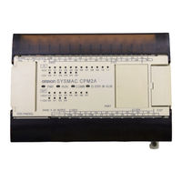
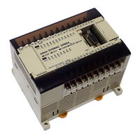
В лабораторном стенде используется промышленный контроллер CPM2A30CDR семейства CPM2A японской фирмы OMRON. Он представляет собой компактный промышленный контроллер класса «микро» с большим числом встроенных функций. Этот контроллер идеально подходит для встраивания в объект управления. На рис. 2.1 показан внешний вид контроллера.
Рис. 2.1. Программируемый контроллер CPM2A-30CDR
14
Пояснения к позиционным обозначениям рис. 2.1 даны в табл. 2.1. Таблица 2.1
|
№ п/п |
Объект |
Описание |
||||
|
Индикатор |
1 |
Есть питание контроллера |
||||
|
питания (PWR) |
0 |
Питания контроллера нет |
||||
|
Индикатор |
1 |
ПК находится в режиме RUN или MONITOR |
||||
|
ПК находится в режиме PROGRAM или |
||||||
|
работы (RUN) |
0 |
|||||
|
случилась фатальная ошибка |
||||||
|
Индикаторы |
||||||
|
Индикатор |
1 |
Связь с внешними устройствами есть |
||||
|
1 |
состояния |
связи (COMM) |
||||
|
0 |
Нет связи с внешними устройствами |
|||||
|
контроллера |
||||||
|
Индикатор |
1 |
Произошла фатальная ошибка (работа ПК |
||||
|
прекращается) |
||||||
|
ошибки (ERR) |
||||||
|
Произошла нефатальная ошибка (работа ПК |
||||||
|
или опасности |
мигает |
|||||
|
(ALM) |
продолжается) |
|||||
|
0 |
Нормальная работа |
|||||
|
2 |
Индикаторы |
входов |
Отображают состояние входов |
|||
|
3 |
Индикаторы выходов |
Отображают состояние выходов |
||||
|
4 |
Переключатель связи |
Переключает режимы связи с периферийными |
||||
|
устройствами |
||||||
|
5 |
Аналоговые регуляторы |
Позволяют регулировать уставку аналогового тайме- |
||||
|
ра |
||||||
|
6 |
Входные клеммы питания |
Подключение питания 24 В постоянного тока |
||||
|
7 |
Клемма функционального за- |
Заземление для защиты от помех и уменьшения рис- |
||||
|
земления |
ка поражения током. |
|||||
|
8 |
Клемма защитного заземления |
Заземление для уменьшения риска поражения током. |
||||
|
9 |
Входные клеммы |
Подключаются к входным цепям |
||||
|
10 |
Выходные клеммы |
Подключаются к выходным цепям |
||||
|
11 |
Отсек для батареи |
В нем находится батарея |
||||
|
Подключение стандартных устройств для програм- |
||||||
|
12 |
Периферийный порт |
мирования и связь по протоколу Host Link или связь |
||||
|
без протокола |
||||||
|
13 |
Порт RS-232C |
Используется для связи по протоколам Host Link, 1:1 |
||||
|
PC Link, 1:1 NT Link или для связи без протокола |
||||||
|
14 |
Гнездо расширения |
Гнездо для подключения дополнительных модулей |
||||
|
расширения |
||||||
Примечания:
1.Протокол Host Link используется для связи с компьютером. Осуществляется через адаптеры RS-232 и RS-422.
2.Связь 1:1 NT Link осуществляется через адаптер RS-232С. При этом контроллер можно подключить к программируемому терминалу.
3.Протокол 1:1 PC Link осуществляет связь с другими контроллерами CPM2*, CPM1*, CQM1, SRM1(-V2), C200HS/HX/HG/HE. При этом используется адаптер RS-232С.
4.Связь без протокола обеспечивает связь с компьютером без адаптеров.
Втабл. 2.2 представлены общие характеристики контроллера СРМ2А-30CDR.
15

Таблица 2.2
|
Параметр |
Характеристика |
|
|
Тип процессора |
СМР2А |
|
|
Высота/глубина модуля про- |
90/90 мм (AC220В) |
|
|
цессора |
||
|
30 (увеличивается до 100 за счет подключения дополнитель- |
||
|
Число входов/выходов |
||
|
ных модулей) |
||
|
Метод управления входа- |
Циклическое сканирование с прямым входом. Обработка с |
|
|
ми/выходами |
непосредственным обновлением |
|
|
Объем программной памяти |
4096 двухбайтных слов |
|
|
Длина команды |
1 шаг на команду, 1…5 слов на команду |
|
|
Типы команд |
Базовые: 14. |
|
|
Специальные: 105 типов, 185 команд |
||
|
Время исполнения |
Базовой команды: 0,64 мкс. |
|
|
Специальной команды: 7,8 мкс. |
||
|
Язык программирования |
Релейно-контактные схемы. Язык инструкций |
|
|
Счетчики/таймеры |
До 256 (общее количество): |
|
|
1-мс таймеры ТМНН; 10-мс таймеры TIMH(15); 100-мс тай- |
||
|
меры TIM; 1-с/10-с таймеры (в зависимости от установленно- |
||
|
го флага) TIML; декрементирующие счетчики CNT; ревер- |
||
|
сивные счетчики CNTR(12) |
||
|
Часы реального времени |
Показывают год, месяц, день недели, час, минуты и секунды |
|
|
(питается от встроенной батареи резервного питания) |
||
|
Энергонезависимое питание |
Память FLASH: программа и память DM только для чтения. |
|
|
Батарея резервного питания – срок службы – 5 лет |
||
|
Аналоговые уставки |
Две уставки (от 0 до 200 – двоично-десятичные) |
|
|
Диагностика |
Есть |
|
|
Защита паролем |
Есть |
|
|
Журнал ошибок |
Есть |
|
|
Встроенные RS-232C и пери- |
Есть |
|
|
ферийный порты |
Host Link, 1:1 РС Link, 1:1 NT Link, CompoBus/S (Slave) |
|
|
Сетевые протоколы |
||
|
Специальные функции (за счет |
Аналоговый ввод/вывод; Модуль температурных датчиков; |
|
|
подключения дополнительных |
Высокоскоростные счетчики (до 20 кГц) |
|
|
модулей) |
Импульсный выход (до 10 кГц) |
2.4. Подключение входных сигналов
Общая характеристика входов контроллера представлена в табл. 2.3.
|
Таблица 2.3 |
||||
|
Параметр |
Входы |
Значение |
||
|
Входное напряжение |
Все |
24В, постоянный ток |
||
|
00000 |
– 00001 |
8 мА |
||
|
Входной ток |
00002 – 00006 |
6 мА |
||
|
00007 |
и другие |
5 мА |
||
|
Напряжение уровня логической 1 |
00000 |
– 00001 |
Минимум 17 В, 5 мА |
|
|
00002 |
и другие |
Минимум 14,5 В, 1 мА |
||
|
Напряжение уровня логического 0 |
Все |
Максимум 5 В, 1мА |
16
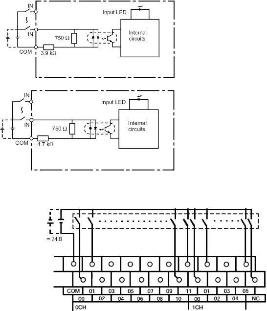
На рис. 2.2 представлены функциональные схемы входов контроллера.
а) 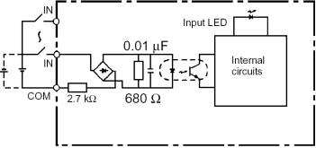
Рис. 2.2. Функциональные схемы входов 00000 – 00001 (а), 00002 – 00006 (б), 00007 – 00011 и 00100 – 00105 (в)
б)
в)
На рис. 2.3 дана схема подключения входов к клеммнику контроллера.
Рис. 2.3. Схема подключения входных сигналов для CPM2A-30CDR
17
На 24 входа имеется только одна общая точка. При этом внешний источник питания подсоединяется одним полюсом к общей точке COM1, а другим – к используемому входу контроллера (полярность не имеет значения).
2.5. Подключение выходных сигналов
Общая характеристика выходов контроллера представлена в табл. 2.4. Таблица 2.4
|
Параметр |
Значение |
|
Тип выхода |
Все выходы релейные |
|
Максимальная нагрузка |
2 А, 5 В постоянного тока |
|
Минимальная нагрузка |
10 мА, 5 В постоянного тока |
|
Прочность реле |
Электрическая: 300 000 операций. |
|
Механическая: 20 000 000 операций |
|
|
Задержка включения в 1 |
Максимум 15 мс. |
|
Задержка выключения в 0 |
Максимум 15 мс. |
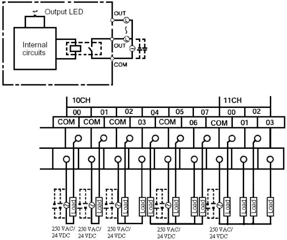
Выходы имеют функциональную схему, представленную на рис. 2.4. На рис. 2.5 приведена схема подключения выходных сигналов к клеммнику контроллера.
Рис. 2.4. Функциональная схема выходов
Рис. 2.5. Схема подключения выходных сигналов контроллера CPM2A
18
У выходов есть свои общие точки (см. рис. 2.5): СОМ1 – выход 01000; СОМ2 – выход 01001;
СОМ3 – выходы 01002, 01003; СОМ4 – выходы 01004 – 01007; СОМ5 – выходы 01100 – 01103; СОМ6 – выходы 01104 – 01107.
2.6.Распределение памяти контроллера
Втабл. 2.5 представлена карта памяти контроллера.
|
Таблица 2.5 |
||||
|
Область памяти |
Слова |
Биты |
Пояснения |
|
|
Область |
IR000 – IR009 |
IR00000 – IR00915 |
По этим адресам можно |
|
|
входов |
(10 слов) |
(160 бит) |
обращаться к внешним |
|
|
IR1 |
Область |
IR010 – IR019 |
IR01000 – IR01915 |
входам/выходам |
|
выходов |
(10 слов) |
(160 бит) |
||
|
Рабочая |
IR020 – IR049 |
IR02000 – IR04915 |
Эти биты можно использо- |
|
|
область |
IR200 – IR227 |
IR20000 – IR22715 |
вать в программе как внут- |
|
|
(58 слов) |
(928 бит) |
ренние переменные |
||
|
SR |
SR228 – SR255 |
SR22800 – SR25515 |
Флаги и биты контроля |
|
|
(28 слов) |
(448 бит) |
|||
|
– |
TR0 – TR7 |
Для временного хранения |
||
|
TR |
информации при ветвлении |
|||
|
в одном шаге программы |
||||
|
HR2 |
HR00 – HR19 |
HR0000 – HR1915 |
Энергонезависимая память |
|
|
(320 бит) |
(сохраняет данные после |
|||
|
выключения питания) |
||||
|
AR2 |
AR00 – AR23 |
AR0000 – AR2315 |
Флаги и биты контроля |
|
|
(384 бит) |
||||
|
LR00 – LR15 |
LR0000 – LR1515 |
Для прямой связи контрол- |
||
|
LR1 |
(256 бит) |
леров между собой |
||
|
Таймеры 2 |
TC000 – TC255 |
Одни и те же номера ис- |
||
|
(номера таймеров/счетчиков)3 |
пользуются для таймеров и |
|||
|
/счетчики |
счетчиков |
|||
|
Чтение |
DM0000 – DM1999 |
– |
В памяти данных можно |
|
|
обращаться только к сло- |
||||
|
DM2022 – DM 2047 |
||||
|
/запись2 |
вам. При выключении пи- |
|||
|
(2026 слов) |
тания данные теряются |
|||
|
Журнал |
DM2000 – DM2001 |
– |
Используется для хранения |
|
|
DM |
ошибок2 |
(22 слова) |
информации об ошибках |
|
|
Только |
DM6144 – DM6599 |
– |
Информация не может |
|
|
чтение4 |
(456 слов) |
быть изменена программой |
||
|
Установки |
DM6600 – DM6655 |
– |
Используется для хранения |
|
|
ПК4 |
(56 слов) |
различных установок кон- |
||
|
троллера |
19
Примечания:
1.Слова из областей памяти IR и LR могут использоваться как рабочие переменные программ, если они не используются по прямому назначению.
2.Содержимое областей памяти HR, AR, TC (таймеры/счетчики), DM (чтение/запись) сохраняются за счет батарейки, встроенной в контроллер. В ее отсутствие данные теряются и при включении принимаются значения по умолчанию.
3.Когда к области TC (таймеры/счетчики) обращаются как к слову, происходит обращение к регистру, в котором хранится текущее значение таймера/счетчика, а если как к биту, то к флагу завершения (Completion Flag).
4.Данные из области DM6144 – DM6655 не могут быть изменены из программы, но их можно редактировать с помощью устройства для программирования. Программа и данные из области DM6144 – DM6655 сохраняются во Flash-памяти.
5.Если используется символ #, то это означает, что используется константа в выбранном формате (табл. 2.6).
|
Таблица 2.6 |
|||||
|
Обозначение |
Размер |
Формат |
Примечания |
||
|
BOOL |
1 |
бит |
двоичный |
Используется для обозначения контактов и катушек |
|
|
CHANNEL |
≥1 слова |
любой |
Одиночное слово или более длинное значение без |
||
|
знака |
|||||
|
DINT |
2 |
слова |
двоичный |
Двоичное целое число |
|
|
INT |
1 |
слово |
двоичный |
Целое число |
|
|
LINT |
4 |
слова |
двоичный |
Длинное целое число |
|
|
REAL |
2 |
слова |
IEEE |
Числа с плавающей точкой. 32-разрядный формат |
|
|
IEEE |
|||||
|
десятичный |
Используется для числовых операндов, которые обо- |
||||
|
NUMBER |
– |
значаются с «#», «&», «+» или «–». Они могут ис- |
|||
|
пользоваться в двоичном или BCD-формате |
|||||
|
UDINT |
2 |
слова |
двоичный |
Двоичное целое число без знака |
|
|
UDINT_BCD |
2 |
слова |
двоично- |
Двоичное целое число BCD-формата без знака |
|
|
десятичный |
|||||
|
UINT |
1 |
слово |
двоичный |
Целое число без знака |
|
|
UINT_BCD |
1 |
слово |
двоично- |
Целое число BCD-формата без знака |
|
|
десятичный |
|||||
|
ULINT |
4 |
слова |
двоичный |
Длинное целое число без знака |
|
|
ULINT_BCD |
4 |
слова |
двоично- |
Длинное целое число BCD-формата без знака |
|
|
десятичный |
2.7. Система команд контроллера СРМ2А
Ниже приводятся команды, используемые при программировании контроллера. Для команд, перед которыми есть символ @, есть модификация, срабатывающая по переднему фронту управляющего сигнала. Если перед такой командой поставить символ @, то она будет срабатывать при поступлении переднего фронта управляющего сигнала в течение одного скана программы. Команды, имеющие код, представлены в табл. 2.7. В табл. 2.8 представлены команды, не имеющие кода.
20

Таблица 2.7
|
Лев. |
Правый разряд |
|||||||||
|
разр. |
0 |
1 |
2 |
3 |
4 |
5 |
6 |
7 |
8 |
9 |
|
0 |
NOP |
END |
IL |
ILC1 |
JMP |
JMC |
@FAL |
FALS |
STEP |
SNXT |
|
1 |
SET |
KEEP |
CNTR |
DIFU |
DIFD |
TIMH |
@WSFT |
@ASFT |
– |
– |
|
2 |
CMP |
@MOV |
@MVN |
@BIN |
@BCD |
@ASL |
@ASR |
@ROL |
@ROR |
@COM |
|
3 |
@ADD |
@SUB |
@MUL |
@DIV |
@ANDW |
@ORW |
@XORW |
@XNRW |
@INC |
@DEC |
|
4 |
@STC |
@CLC |
– |
– |
– |
– |
@MSG |
@RXD |
@TXD |
– |
|
5 |
@ADB |
@SBB |
@MLB |
@DVB |
@ADDL |
@SUBL |
@MULL |
@DIVL |
@BINL |
@BCDL |
|
6 |
CMPL |
@INI |
@PRV |
@CTBL |
@SPED |
@PULS |
@SCL |
@BCNT |
@BCMP |
@STIM |
|
7 |
@XFER |
@BSET |
– |
@XCHG |
@SLD |
@SRD |
@MLPX |
@DMPX |
@SDEC |
– |
|
8 |
@DIST |
@COLL |
@MOVB |
@MOVD |
@SFTR |
@TCMP |
@ASC |
– |
– |
@INT |
|
9 |
– |
@SBS |
SBN |
RET |
– |
– |
– |
@IORF |
– |
@MCRO |
Таблица 2.8
|
AND |
AND |
AVG |
AVERAGE VALUE |
|
|
AND NOT |
AND NOT |
@FCS |
FCS CALCULATE |
|
|
AND LD |
AND LOAD |
@MAX |
FIND MAXIMUM |
|
|
CNT |
COUNTER |
@MIN |
FIND MINIMUM |
|
|
LD |
LOAD |
@NEG |
2’S COMPLEMENT |
|
|
LD NOT |
LOAD NOT |
PID |
PID CONTROL |
|
|
OR |
OR |
@PWM |
PULSE WITH VARIABLE DUTY RATIO |
|
|
OR LD |
OR LOAD |
@SCL2 |
SIGNED BINARY TO BCD SCALLING |
|
|
OR NOT |
OR NOT |
@SCL3 |
BCD TO SIGNED BINARY SCALLING |
|
|
OUT |
OUTPUT |
@SEC |
HOURS TO SECONDS |
|
|
OUT NOT |
OUTPUT NOT |
@SRCH |
DATA SEARCH |
|
|
RSET |
RESET |
@SUM |
SUM |
|
|
SET |
SET |
@XFRB |
TRANSFER BITS |
|
|
TIM |
TIMER |
ZCP |
AREA RANGE COMPARE |
|
|
TIML |
LONG TIMER |
ZCPL |
DOUBLE AREA RANGE COMPARE |
|
|
TMHH |
VERY HIGHSPEED TIMER |
@STUP |
CHANGE RS-232 SETUP |
|
|
@ACC |
ACCELERATION CON- |
SYNC |
SYNHRONIZED PULSE CONTROL |
|
|
TROL |
||||
2.8. Примеры использования команд
Далее приведены примеры использования некоторых команд (для более полного изучения системы команд необходимо воспользоваться руководством по программированию контроллеров SYSMAC CPM2A).
21
AND, ANDLD, ANDNOT, LD, LDNOT, OR, ORLD, ORNOT – команды релей-
но-контактной схемы
|
Области операндов |
В |
Бит |
IR, SR, AR, HR, TC, LR, TR |
Ограничений количества любой из этих команд или порядка их применения нет, если программа вмещается в отведенную память. Ниже приведены примеры использования этих команд.
Контроллер использует два языка программирования: язык релейноконтактных схем РКС (лестничных диаграмм) и язык инструкций.
В табл. 2.9 представлен внешний вид элементов, используемых при составлении релейно-контактных схем.
Таблица 2.9
|
Элемент |
Описание |
|
Замыкающий контакт |
|
|
Размыкающий контакт |
|
|
Соединительная вертикальная линия |
|
|
Соединительная вертикальная линия |
|
|
Выход |
Выход с инверсией
Функциональный блок
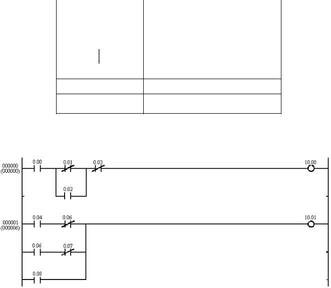
На рис. 2.6 приведен пример использования рассматриваемых команд на языке РКС, а в табл. 2.10 представлена та же программа на языке инструкций.
Рис. 2.6. Пример программы на языке РКС
22
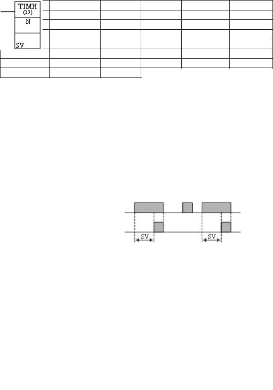
Таблица 2.10
|
Адрес |
Инструкция |
Операнд |
Адрес |
Инструкция |
Операнд |
|
00000 |
LD |
0.00 |
00007 |
ANDNOT |
0.06 |
|
00001 |
LDNOT |
0.01 |
00008 |
LD |
0.06 |
|
00002 |
OR |
0.02 |
00009 |
ANDNOT |
0.07 |
|
00003 |
ANDLD |
00010 |
ORLD |
||
|
00004 |
ANDNOT |
0.03 |
00011 |
OR |
0.08 |
|
00005 |
OUT |
10.00 |
00012 |
OUT |
10.01 |
|
00006 |
LD |
0.04 |
Обозначение таймера TIM в программе имеет вид:
|
Области операндов |
N |
Номер таймера |
# |
|
SV |
Заданное значение (сло- |
IR, SR, AR, HR, LR, DM, |
|
|
во BCD) |
# |
Если время включения входного сигнала меньше времени уставки (рис. 2.7), то выход таймера не включается.
Фаза завершения
Условие выполнения
Рис. 2.7. Циклограмма работы таймера
Заданные значения лежат в диапазоне 000,0…999,9. Десятичная точка не вводится. Каждый номер ТС от 000 до 255 (номер записывается в десятичном формате) можно использовать в качестве определителя только для одной команды таймера или счетчика. ТС 000–ТС 015 рекомендуется использовать в команде задания TIM, только если они не требуются для команды TIMH(15).
Обозначение высокоскоростного таймера TIMH(15) в программе имеет вид:
|
Области операндов |
N |
Номер таймера |
# |
|
SV |
Заданное значение (сло- |
IR, SR, AR, HR, LR, DM, |
|
|
во BCD) |
# |
Заданные значения лежат в диапазоне 00,00…99,99 (хотя можно ввести 00,00 и 00,01. 00,00 запретит таймер, т.е. сразу включает флаг завершения, а 00,01 не будет надежно считан). Десятичная точка не вводится.
23
Соседние файлы в папке АТПП-2
- #
- #
- #
- #

OPERATION MANUAL
Programmable Controllers
SYSMAC
CPM2A
Cat. No. W352-E1-07

CPM2A Programmable Controllers
Operation Manual
Revised November 2005

iv

Notice:
OMRON products are manufactured for use according to proper procedures by a qualified operator
and only for the purposes described in this manual.
The following conventions are used to indicate and classify precautions in this manual. Always heed
the information provided with them. Failure to heed precautions can result in injury to people or damage to property.
DANGER Indicates an imminently hazardous situation which, if not avoided, will result in death or
!
serious injury. Additionally, there may be severe property damage.
WARNING Indicates a potentially hazardous situation which, if not avoided, could result in death or
!
serious injury. Additionally, there may be severe property damage.
Caution Indicates a potentially hazardous situation which, if not avoided, may result in minor or
!
moderate injury, or property damage.
OMRON Product References
All OMRON products are capitalized in this manual. The word “Unit” is also capitalized when it refers
to an OMRON product, regardless of whether or not it appears in the proper name of the product.
The abbreviation “Ch,” which appears in some displays and on some OMRON products, often means
“word” and is abbreviated “Wd” in documentation in this sense.
The abbreviation “PC” means Programmable Controller and is not used as an abbreviation for anything else.
Visual Aids
The following headings appear in the left column of the manual to help you locate different types of
information.
OMRON, 1999
All rights reserved. No part of this publication may be reproduced, stored in a retrieval system, or transmitted, in any
form, or by any means, mechanical, electronic, photocopying, recording, or otherwise, without the prior written permission of OMRON.
No patent liability is assumed with respect to the use of the information contained herein. Moreover, because OMRON is
constantly striving to improve its high-quality products, the information contained in this manual is subject to change
without notice. Every precaution has been taken in the preparation of this manual. Nevertheless, OMRON assumes no
responsibility for errors or omissions. Neither is any liability assumed for damages resulting from the use of the information contained in this publication.
Note Indicates information of particular interest for efficient and convenient operation
of the product.
1, 2, 3… 1. Indicates lists of one sort or another, such as procedures, checklists, etc.
v

vi

TABLE OF CONTENTS
PRECAUTIONS xv. . . . . . . . . . . . . . . . . . . . . . . . . . . . . . . . .
1 Intended Audience xvi. . . . . . . . . . . . . . . . . . . . . . . . . . . . . . . . . . . . . . . . . . . . . . . . . . . . . . . . . . .
2 General Precautions xvi. . . . . . . . . . . . . . . . . . . . . . . . . . . . . . . . . . . . . . . . . . . . . . . . . . . . . . . . . .
3 Safety Precautions xvi. . . . . . . . . . . . . . . . . . . . . . . . . . . . . . . . . . . . . . . . . . . . . . . . . . . . . . . . . . .
4 Operating Environment Precautions xvii. . . . . . . . . . . . . . . . . . . . . . . . . . . . . . . . . . . . . . . . . . . . .
5 Application Precautions xviii. . . . . . . . . . . . . . . . . . . . . . . . . . . . . . . . . . . . . . . . . . . . . . . . . . . . . .
6 EC Directives xx. . . . . . . . . . . . . . . . . . . . . . . . . . . . . . . . . . . . . . . . . . . . . . . . . . . . . . . . . . . . . .
7 CPM2A 24-VDC CPU Unit Conformance to NK Standards xxiii. . . . . . . . . . . . . . . . . . . . . . . . . .
SECTION 1
Introduction 1. . . . . . . . . . . . . . . . . . . . . . . . . . . . . . . . . . . .
1-1 CPM2A Features and Functions 2. . . . . . . . . . . . . . . . . . . . . . . . . . . . . . . . . . . . . . . . . . . .
1-2 Basic System Configurations 9. . . . . . . . . . . . . . . . . . . . . . . . . . . . . . . . . . . . . . . . . . . . . . .
1-3 Structure and Operation 12. . . . . . . . . . . . . . . . . . . . . . . . . . . . . . . . . . . . . . . . . . . . . . . . . . .
1-4 Functions Listed by Usage 18. . . . . . . . . . . . . . . . . . . . . . . . . . . . . . . . . . . . . . . . . . . . . . . . .
1-5 Comparison with the CPM1A 21. . . . . . . . . . . . . . . . . . . . . . . . . . . . . . . . . . . . . . . . . . . . . .
1-6 Preparation for Operation 26. . . . . . . . . . . . . . . . . . . . . . . . . . . . . . . . . . . . . . . . . . . . . . . . . .
SECTION 2
Unit Specifications and Components 29. . . . . . . . . . . . . . . .
2-1 Specifications 30. . . . . . . . . . . . . . . . . . . . . . . . . . . . . . . . . . . . . . . . . . . . . . . . . . . . . . . . . . .
2-2 Unit Components 37. . . . . . . . . . . . . . . . . . . . . . . . . . . . . . . . . . . . . . . . . . . . . . . . . . . . . . . .
SECTION 3
Installation and Wiring 47. . . . . . . . . . . . . . . . . . . . . . . . . . .
3-1 Design Precautions 48. . . . . . . . . . . . . . . . . . . . . . . . . . . . . . . . . . . . . . . . . . . . . . . . . . . . . . .
3-2 Selecting an Installation Site 48. . . . . . . . . . . . . . . . . . . . . . . . . . . . . . . . . . . . . . . . . . . . . . .
3-3 Installing the CPM2A 50. . . . . . . . . . . . . . . . . . . . . . . . . . . . . . . . . . . . . . . . . . . . . . . . . . . . .
3-4 Wiring and Connections 53. . . . . . . . . . . . . . . . . . . . . . . . . . . . . . . . . . . . . . . . . . . . . . . . . . .
SECTION 4
Using a Programming Console 89. . . . . . . . . . . . . . . . . . . . .
4-1 Compatible Programming Consoles 90. . . . . . . . . . . . . . . . . . . . . . . . . . . . . . . . . . . . . . . . .
4-2 Programming Console Operations 96. . . . . . . . . . . . . . . . . . . . . . . . . . . . . . . . . . . . . . . . . . .
4-3 Programming Example 120. . . . . . . . . . . . . . . . . . . . . . . . . . . . . . . . . . . . . . . . . . . . . . . . . . . .
SECTION 5
Test Runs and Error Processing 127. . . . . . . . . . . . . . . . . . . .
5-1 Initial System Checks and Test Run Procedure 128. . . . . . . . . . . . . . . . . . . . . . . . . . . . . . . . .
5-2 Self-diagnostic Functions 129. . . . . . . . . . . . . . . . . . . . . . . . . . . . . . . . . . . . . . . . . . . . . . . . . .
5-3 Programming Console Operation Errors 132. . . . . . . . . . . . . . . . . . . . . . . . . . . . . . . . . . . . . .
5-4 Programming Errors 132. . . . . . . . . . . . . . . . . . . . . . . . . . . . . . . . . . . . . . . . . . . . . . . . . . . . . .
5-5 Troubleshooting Flowcharts 133. . . . . . . . . . . . . . . . . . . . . . . . . . . . . . . . . . . . . . . . . . . . . . . .
5-6 Maintenance Inspections 141. . . . . . . . . . . . . . . . . . . . . . . . . . . . . . . . . . . . . . . . . . . . . . . . . .
5-7 Battery Replacement 142. . . . . . . . . . . . . . . . . . . . . . . . . . . . . . . . . . . . . . . . . . . . . . . . . . . . .
SECTION 6
Expansion Memory Unit 145. . . . . . . . . . . . . . . . . . . . . . . . . .
6-1 Overview 146. . . . . . . . . . . . . . . . . . . . . . . . . . . . . . . . . . . . . . . . . . . . . . . . . . . . . . . . . . . . . .
6-2 Specifications and Nomenclature 147. . . . . . . . . . . . . . . . . . . . . . . . . . . . . . . . . . . . . . . . . . .
6-3 Handling 148. . . . . . . . . . . . . . . . . . . . . . . . . . . . . . . . . . . . . . . . . . . . . . . . . . . . . . . . . . . . . . .
vii

TABLE OF CONTENTS
Appendices
A Standard Models 155. . . . . . . . . . . . . . . . . . . . . . . . . . . . . . . . . . . . . . . . . . . . . . . . . . . . . . . . . . .
B Dimensions 159. . . . . . . . . . . . . . . . . . . . . . . . . . . . . . . . . . . . . . . . . . . . . . . . . . . . . . . . . . . . . . . .
Index 167. . . . . . . . . . . . . . . . . . . . . . . . . . . . . . . . . . . . . . . . . .
Revision History 171. . . . . . . . . . . . . . . . . . . . . . . . . . . . . . . . .
viii

About this Manual:
The CPM2A is a compact, high-speed Programmable Controller (PC) designed for control operations in
systems requiring from 10 to 120 I/O points per PC. There are two manuals describing the setup and
operation of the CPM2A: The CPM2A Operation Manual (this manual) and the CPM1/CPM1A/CPM2A/
CPM2C/SRM1(-V2) Programming Manual (W353). (The CPM1/CPM1A/CPM2A/CPM2C/SRM1(-V2)
Programming Manual is referred to as simply the Programming Manual in this manual.)
This manual describes the system configuration and installation of the CPM2A and provides a basic
explanation of operating procedures for the Programming Consoles. It also introduces the capabilities of
CX-Programmer, the SYSMAC Support Software (SSS) and SYSMAC-CPT Support Software. Read this
manual first to acquaint yourself with the CPM2A.
The Programming Manual (W353) provides detailed descriptions of the CPM2A’s programming functions
and application methods for Expansion Units. The SYSMAC Support Software Operation Manuals:
Basics and C-series PCs (W247 and W248) provide descriptions of SSS operations for the CPM2A and
other SYSMAC C-series PCs. The WS02-CXPjj-E CX-Programmer Operation Manual (W414) provides details of operations for the WS02-CXPjj-E CX-Programmer. The SYSMAC-CPT Support Soft-
ware Quick Start Guide (W332) and User Manual (W333) provide descriptions of ladder diagram operations in the Windows environment.
Please read this manual carefully and be sure you understand the information provided before attempting
to install and operate the CPM2A.
Section 1 gives a brief overview of the steps involved in developing of a CPM2A System, describes the
possible system configurations, and describes the CPM2A’s special features and functions.
Section 2 provides the technical specifications of the Units that go together to create a CPM2A PC and
describes the main components of the Units.
Section 3 describes how to install and wire a CPM2A PC.
Section 4 describes how to connect the Programming Console, and how to perform the various program-
ming operations.
Section 5 describes how to perform a test run and how to diagnose and correct the hardware and software errors that can occur during PC operation.
Section 6 describes how to use the CPM1-EMU01-V1 Expansion Memory Unit. Follow the handling precautions and procedures to properly use the Unit.
Appendix A provides tables of CPM2A Units and related products.
Appendix B provides the dimensions of CPM2A Units.
!
WARNING Failure to read and understand the information provided in this manual may result in
personal injury or death, damage to the product, or product failure. Please read each
section in its entirety and be sure you understand the information provided in the section
and related sections before attempting any of the procedures or operations given.
ix

Read and Understand this Manual
Please read and understand this manual before using the product. Please consult your OMRON
representative if you have any questions or comments.
Warranty and Limitations of Liability
WARRANTY
OMRON’s exclusive warranty is that the products are free from defects in materials and workmanship for
БББББББББББББББББББББББББББББББ
a period of one year (or other period if specified) from date of sale by OMRON.
БББББББББББББББББББББББББББББББ
OMRON MAKES NO WARRANTY OR REPRESENTATION, EXPRESS OR IMPLIED, REGARDING
БББББББББББББББББББББББББББББББ
NON–INFRINGEMENT, MERCHANTABILITY, OR FITNESS FOR PARTICULAR PURPOSE OF THE
БББББББББББББББББББББББББББББББ
PRODUCTS. ANY BUYER OR USER ACKNOWLEDGES THAT THE BUYER OR USER ALONE HAS
БББББББББББББББББББББББББББББББ
DETERMINED THAT THE PRODUCTS WILL SUITABLY MEET THE REQUIREMENTS OF THEIR
INTENDED USE. OMRON DISCLAIMS ALL OTHER WARRANTIES, EXPRESS OR IMPLIED.
БББББББББББББББББББББББББББББББ
БББББББББББББББББББББББББББББББ
LIMITATIONS OF LIABILITY
OMRON SHALL NOT BE RESPONSIBLE FOR SPECIAL, INDIRECT, OR CONSEQUENTIAL
DAMAGES, LOSS OF PROFITS OR COMMERCIAL LOSS IN ANY WAY CONNECTED WITH THE
БББББББББББББББББББББББББББББББ
PRODUCTS, WHETHER SUCH CLAIM IS BASED ON CONTRACT, WARRANTY, NEGLIGENCE, OR
БББББББББББББББББББББББББББББББ
STRICT LIABILITY.
БББББББББББББББББББББББББББББББ
In no event shall the responsibility of OMRON for any act exceed the individual price of the product on
БББББББББББББББББББББББББББББББ
which liability is asserted.
БББББББББББББББББББББББББББББББ
IN NO EVENT SHALL OMRON BE RESPONSIBLE FOR WARRANTY, REPAIR, OR OTHER CLAIMS
БББББББББББББББББББББББББББББББ
REGARDING THE PRODUCTS UNLESS OMRON’S ANALYSIS CONFIRMS THAT THE PRODUCTS
БББББББББББББББББББББББББББББББ
WERE PROPERLY HANDLED, STORED, INSTALLED, AND MAINTAINED AND NOT SUBJECT TO
БББББББББББББББББББББББББББББББ
CONTAMINATION, ABUSE, MISUSE, OR INAPPROPRIATE MODIFICATION OR REPAIR.
xi

Application Considerations
SUITABILITY FOR USE
OMRON shall not be responsible for conformity with any standards, codes, or regulations that apply to
БББББББББББББББББББББББББББББББ
the combination of products in the customer’s application or use of the products.
БББББББББББББББББББББББББББББББ
At the customer’s request, OMRON will provide applicable third party certification documents identifying
БББББББББББББББББББББББББББББББ
ratings and limitations of use that apply to the products. This information by itself is not sufficient for a
БББББББББББББББББББББББББББББББ
complete determination of the suitability of the products in combination with the end product, machine,
БББББББББББББББББББББББББББББББ
system, or other application or use.
БББББББББББББББББББББББББББББББ
The following are some examples of applications for which particular attention must be given. This is not
БББББББББББББББББББББББББББББББ
intended to be an exhaustive list of all possible uses of the products, nor is it intended to imply that the
БББББББББББББББББББББББББББББББ
uses listed may be suitable for the products:
БББББББББББББББББББББББББББББББ
• Outdoor use, uses involving potential chemical contamination or electrical interference, or conditions
БББББББББББББББББББББББББББББББ
or uses not described in this manual.
БББББББББББББББББББББББББББББББ
• Nuclear energy control systems, combustion systems, railroad systems, aviation systems, medical
БББББББББББББББББББББББББББББББ
equipment, amusement machines, vehicles, safety equipment, and installations subject to separate
БББББББББББББББББББББББББББББББ
industry or government regulations.
БББББББББББББББББББББББББББББББ
• Systems, machines, and equipment that could present a risk to life or property.
БББББББББББББББББББББББББББББББ
Please know and observe all prohibitions of use applicable to the products.
БББББББББББББББББББББББББББББББ
БББББББББББББББББББББББББББББББ
NEVER USE THE PRODUCTS FOR AN APPLICATION INVOLVING SERIOUS RISK TO LIFE OR
БББББББББББББББББББББББББББББББ
PROPERTY WITHOUT ENSURING THAT THE SYSTEM AS A WHOLE HAS BEEN DESIGNED TO
ADDRESS THE RISKS, AND THAT THE OMRON PRODUCTS ARE PROPERLY RATED AND
БББББББББББББББББББББББББББББББ
INSTALLED FOR THE INTENDED USE WITHIN THE OVERALL EQUIPMENT OR SYSTEM.
БББББББББББББББББББББББББББББББ
БББББББББББББББББББББББББББББББ
PROGRAMMABLE PRODUCTS
OMRON shall not be responsible for the user’s programming of a programmable product, or any
БББББББББББББББББББББББББББББББ
consequence thereof.
xii

Disclaimers
CHANGE IN SPECIFICATIONS
БББББББББББББББББББББББББББББББ
Product specifications and accessories may be changed at any time based on improvements and other
reasons.
БББББББББББББББББББББББББББББББ
БББББББББББББББББББББББББББББББ
It is our practice to change model numbers when published ratings or features are changed, or when
significant construction changes are made. However, some specifications of the products may be
БББББББББББББББББББББББББББББББ
changed without any notice. When in doubt, special model numbers may be assigned to fix or establish
БББББББББББББББББББББББББББББББ
key specifications for your application on your request. Please consult with your OMRON representative
БББББББББББББББББББББББББББББББ
at any time to confirm actual specifications of purchased products.
БББББББББББББББББББББББББББББББ
DIMENSIONS AND WEIGHTS
Dimensions and weights are nominal and are not to be used for manufacturing purposes, even when
tolerances are shown.
БББББББББББББББББББББББББББББББ
PERFORMANCE DATA
Performance data given in this manual is provided as a guide for the user in determining suitability and
БББББББББББББББББББББББББББББББ
does not constitute a warranty. It may represent the result of OMRON’s test conditions, and the users
БББББББББББББББББББББББББББББББ
must correlate it to actual application requirements. Actual performance is subject to the OMRON
БББББББББББББББББББББББББББББББ
Warranty and Limitations of Liability.
БББББББББББББББББББББББББББББББ
The information in this manual has been carefully checked and is believed to be accurate; however, no
responsibility is assumed for clerical, typographical, or proofreading errors, or omissions.
БББББББББББББББББББББББББББББББ
ERRORS AND OMISSIONS
xiii

xiv

PRECAUTIONS
This section provides general precautions for using the Programmable Controller (PC) and related devices.
The information contained in this section is important for the safe and reliable application of the Programmable Controller. You must read this section and understand the information contained before attempting to set up or operate a
PC system.
1 Intended Audience xvi. . . . . . . . . . . . . . . . . . . . . . . . . . . . . . . . . . . . . . . . . . . . . . . . . . . . . . . . . . . .
2 General Precautions xvi. . . . . . . . . . . . . . . . . . . . . . . . . . . . . . . . . . . . . . . . . . . . . . . . . . . . . . . . . . .
3 Safety Precautions xvi. . . . . . . . . . . . . . . . . . . . . . . . . . . . . . . . . . . . . . . . . . . . . . . . . . . . . . . . . . . .
4 Operating Environment Precautions xvii. . . . . . . . . . . . . . . . . . . . . . . . . . . . . . . . . . . . . . . . . . . . . .
5 Application Precautions xviii. . . . . . . . . . . . . . . . . . . . . . . . . . . . . . . . . . . . . . . . . . . . . . . . . . . . . . . .
6 EC Directives xx. . . . . . . . . . . . . . . . . . . . . . . . . . . . . . . . . . . . . . . . . . . . . . . . . . . . . . . . . . . . . . . .
7 CPM2A 24-VDC CPU Unit Conformance to NK Standards xxiii. . . . . . . . . . . . . . . . . . . . . . . . . . .
xv

1 Intended Audience
This manual is intended for the following personnel, who must also have knowledge of electrical systems (an electrical engineer or the equivalent).
• Personnel in charge of installing FA systems.
• Personnel in charge of designing FA systems.
• Personnel in charge of managing FA systems and facilities.
2 General Precautions
The user must operate the product according to the performance specifications
described in the operation manuals.
Before using the product under conditions which are not described in the manual
or applying the product to nuclear control systems, railroad systems, aviation
systems, vehicles, combustion systems, medical equipment, amusement machines, safety equipment, and other systems, machines, and equipment that
may have a serious influence on lives and property if used improperly, consult
your OMRON representative.
Make sure that the ratings and performance characteristics of the product are
sufficient for the systems, machines, and equipment, and be sure to provide the
systems, machines, and equipment with double safety mechanisms.
This manual provides information for programming and operating the Unit. Be
sure to read this manual before attempting to use the Unit and keep this manual
close at hand for reference during operation.
5Safety Precautions
WARNING It is extremely important that a PC and all PC Units be used for the specified
!
purpose and under the specified conditions, especially in applications that can
directly or indirectly affect human life. You must consult with your OMRON
representative before applying a PC System to the above-mentioned
applications.
3 Safety Precautions
WARNING Do not attempt to take any Unit apart while the power is being supplied. Doing so
!
may result in electric shock.
WARNING Do not touch any of the terminals or terminal blocks while the power is being
!
supplied. Doing so may result in electric shock.
WARNING Do not attempt to disassemble, repair, or modify any Units. Any attempt to do so
!
may result in malfunction, fire, or electric shock.
WARNING Provide safety measures in external circuits (i.e., not in the Programmable
!
Controller), including the following items, in order to ensure safety in the system
if an abnormality occurs due to malfunction of the PC or another external factor
affecting the PC operation. Not doing so may result in serious accidents.
xvi
• Emergency stop circuits, interlock circuits, limit circuits, and similar safety
measures must be provided in external control circuits.
• The PC will turn OFF all outputs when its self-diagnosis function detects any
error or when a severe failure alarm (FALS) instruction is executed. As a countermeasure for such errors, external safety measures must be provided to ensure safety in the system.

Operating Environment Precautions
• The PC outputs may remain ON or OFF due to deposition or burning of the
output relays or destruction of the output transistors. As a countermeasure for
such problems, external safety measures must be provided to ensure safety in
the system.
• When the 24-VDC output (service power supply to the PC) is overloaded or
short-circuited, the voltage may drop and result in the outputs being turned
OFF. As a countermeasure for such problems, external safety measures must
be provided to ensure safety in the system.
WARNING When transferring programs to other nodes, or when making changes to I/O
!
memory, confirm the safety of the destination node before transfer. Not doing so
may result in injury.
Caution Execute online edit only after confirming that no adverse effects will be caused
!
by extending the cycle time. Otherwise, the input signals may not be readable.
Caution Tighten the screws on the terminal block of the AC Power Supply Unit to the
!
torque specified in the operation manual. The loose screws may result in burning
or malfunction.
4
Caution When connecting the PC to a personal computer or other peripheral device, ei-
!
ther ground the 0-V side of the PC or do not ground the PC at all. Although some
grounding methods short the 24-V side, as shown in the following diagram, never do so with the PC.
INCORRECT Grounding: Shorting the 24-V side of the Power Supply
Non-isolated DC
0 V
power supply
0 V 0 V
PC
24 V
4 Operating Environment Precautions
Caution Do not operate the control system in the following places:
!
• Locations subject to direct sunlight.
• Locations subject to temperatures or humidity outside the range specified in
the specifications.
• Locations subject to condensation as the result of severe changes in tempera-
ture.
• Locations subject to corrosive or flammable gases.
• Locations subject to dust (especially iron dust) or salts.
• Locations subject to exposure to water, oil, or chemicals.
• Locations subject to shock or vibration.
Peripheral device
Caution Take appropriate and sufficient countermeasures when installing systems in the
!
following locations:
xvii

• Locations subject to static electricity or other forms of noise.
• Locations subject to strong electromagnetic fields.
• Locations subject to possible exposure to radioactivity.
• Locations close to power supplies.
Caution The operating environment of the PC System can have a large effect on the lon-
!
gevity and reliability of the system. Improper operating environments can lead to
malfunction, failure, and other unforeseeable problems with the PC System. Be
sure that the operating environment is within the specified conditions at installation and remains within the specified conditions during the life of the system.
5 Application Precautions
Observe the following precautions when using the PC System.
WARNING Always heed these precautions. Failure to abide by the following precautions
!
could lead to serious or possibly fatal injury.
• Always connect to a ground such that the grounding resistance does not exceed 100 Ω when installing the Units. Not connecting to the correct ground
may result in electric shock.
• Always turn OFF the power supply to the PC before attempting any of the following. Not turning OFF the power supply may result in malfunction or electric
shock.
• Mounting or dismounting I/O Units, CPU Units, or any other Units.
• Assembling the Units.
• Setting DIP switches or rotary switches.
• Connecting or wiring the cables.
• Connecting or disconnecting the connectors.
5Application Precautions
Caution Failure to abide by the following precautions could lead to faulty operation of the
!
PC or the system, or could damage the PC or PC Units. Always heed these precautions.
• Fail-safe measures must be taken by the customer to ensure safety in the
event of incorrect, missing, or abnormal signals caused by broken signal lines,
momentary power interruptions, or other causes.
• Construct a control circuit so that power supply for the I/O circuits does not
come ON before power supply for the Unit. If power supply for the I/O circuits
comes ON before power supply for the Unit, normal operation may be temporarily interrupted.
• If the operating mode is changed from RUN or MONITOR mode to PROGRAM
mode, with the IOM Hold Bit ON, the output will hold the most recent status. In
such a case, ensure that the external load does not exceed specifications. (If
operation is stopped because of an operation error (including FALS instructions), the values in the internal memory of the CPU Unit will be saved, but the
outputs will all turn OFF.)
• Always use the power supply voltage specified in the operation manuals. An
incorrect voltage may result in malfunction or burning.
• Take appropriate measures to ensure that the specified power with the rated
voltage and frequency is supplied. Be particularly careful in places where the
power supply is unstable. An incorrect power supply may result in malfunction.
• Install external breakers and take other safety measures against short-circuiting in external wiring. Insufficient safety measures against short-circuiting may
result in burning.
xviii

Application Precautions
5
• Do not apply voltages to the input terminals in excess of the rated input voltage.
Excess voltages may result in burning.
• Do not apply voltages or connect loads to the output terminals in excess of the
maximum switching capacity. Excess voltage or loads may result in burning.
• Disconnect the functional ground terminal when performing withstand voltage
tests. Not disconnecting the functional ground terminal may result in burning.
• Install the Unit properly as specified in the operation manual. Improper installation of the Unit may result in malfunction.
• Be sure that all the mounting screws, terminal screws, and cable connector
screws are tightened to the torque specified in the relevant manuals. Incorrect
tightening torque may result in malfunction.
• Be sure to leave the labels attached at the time of shipment on the CPM1 or
CPM2A when wiring in order to prevent wiring cuttings from entering the Unit.
• Remove the label after the completion of wiring to ensure proper heat dissipation. Leaving the label attached may result in malfunction.
• Be sure to perform wiring in accordance with the relevant operation manual.
Incorrect wiring may result in burning.
• Use crimp terminals for wiring. Do not connect bare stranded wires directly to
terminals. Connection of bare stranded wires may result in burning.
• Double-check all the wiring before turning ON the power supply. Incorrect wiring may result in burning.
• Be sure that the terminal blocks, expansion cables, and other items with locking devices are properly locked into place. Improper locking may result in malfunction.
• Be sure that terminal blocks and connectors are connected in the specified direction with the correct polarity. Not doing so may result in malfunction.
• Check the user program for proper execution before actually running it on the
Unit. Not checking the program may result in an unexpected operation.
• Confirm that no adverse effect will occur in the system before attempting any of
the following. Not doing so may result in an unexpected operation.
• Changing the operating mode of the PC.
• Force-setting/force-resetting any bit in memory.
• Changing the present value of any word or any set value in memory.
• Resume operation only after transferring to the new CPU Unit the contents of
the DM and HR Areas required for resuming operation. Not doing so may result
in an unexpected operation.
• Do not pull on the cables or bend the cables beyond their natural limit. Doing
either of these may break the cables.
• Do not place objects on top of the cables. Doing so may break the cables.
• Do not short the battery terminals or charge, disassemble, heat, or incinerate
the battery. Do not subject the battery to strong shocks. Doing any of these
may result in leakage, rupture, heat generation, or ignition of the battery. Dispose of any battery that has been dropped on the floor or otherwise subjected
to excessive shock. Batteries that have been subjected to shock may leak if
they are used.
• When replacing parts, be sure to confirm that the rating of a new part is correct.
Not doing so may result in malfunction or burning.
• Before touching the Unit, be sure to first touch a grounded metallic object in
order to discharge any static build-up. Not doing so may result in malfunction or
damage.
• Do not touch the expansion I/O connecting cable while the power is being supplied in order to prevent any malfunction due to static electricity.
xix

• When using a thermocouple-input type Temperature Sensor Unit, observe the
following precautions:
• Do not remove the cold junction compensator attached at the time of deliv-
ery. If the cold junction compensator is removed the Unit will not be able to
measure temperatures correctly.
• Each of the input circuits is calibrated with the cold junction compensator
attached to the Unit. If the Unit is used with the cold junction compensator
from other Units, the Unit will not be able to measure temperatures correctly.
• Do not touch the cold junction compensator. Doing so may result in incor-
rect temperature measurement.
6 EC Directives
6-1 Applicable Directives
• EMC Directives
• Low Voltage Directive
6-2 Concepts
EMC Directives
OMRON devices that comply with EC Directives also conform to the related
EMC standards so that they can be more easily built into other devices or the
overall machine. The actual products have been checked for conformity to EMC
standards (see the following note). Whether the products conform to the standards in the system used by the customer, however, must be checked by the
customer.
EMC-related performance of the OMRON devices that comply with EC Directives will vary depending on the configuration, wiring, and other conditions of the
equipment or control panel on which the OMRON devices are installed. The customer must, therefore, perform the final check to confirm that devices and the
overall machine conform to EMC standards.
6EC Directives
Note Applicable EMC (Electromagnetic Compatibility) standards are as follows:
EMS (Electromagnetic Susceptibility): EN61131-2
EMI (Electromagnetic Interference): EN61000-6-4
Low Voltage Directive
Always ensure that devices operating at voltages of 50 to 1,000 VAC and 75 to
1,500 VDC meet the required safety standards for the PC (EN61131-2).
6-3 Conformance to EC Directives
The CPM2A PCs comply with EC Directives. To ensure that the machine or device in which the CPM2A PC is used complies with EC directives, the PC must be
installed as follows:
1, 2, 3… 1. The CPM2A PC must be installed within a control panel.
2. Reinforced insulation or double insulation must be used for the DC power
supplies used for the communications and I/O power supplies.
3. CPM2A PCs complying with EC Directives also conform to the Common
Emission Standard (EN61000-6-4). Radiated emission characteristics
(10-m regulations) may vary depending on the configuration of the control
panel used, other devices connected to the control panel, wiring, and other
conditions. You must therefore confirm that the overall machine or equipment complies with EC Directives.
(Radiated emission: 10-m regulations)
xx

EC Directives
6-4 Relay Output Noise Reduction Methods
The CPM2A PCs conform to the Common Emission Standards (EN61000-6-4)
of the EMC Directives. However, the noise generated when the PC is switched
ON or OFF using the relay output may not satisfy these standards. In such a
case, a noise filter must be connected to the load side or other appropriate countermeasures must be provided external to the PC.
Countermeasures taken to satisfy the standards vary depending on the devices
on the load side, wiring, configuration of machines, etc. Following are examples
of countermeasures for reducing the generated noise.
Countermeasures
(Refer to EN61000-6-4 for more details.)
Countermeasures are not required if the frequency of load switching for the
whole system with the PC included is less than 5 times per minute.
Countermeasures are required if the frequency of load switching for the whole
system with the PC included is 5 times or more per minute.
6
xxi
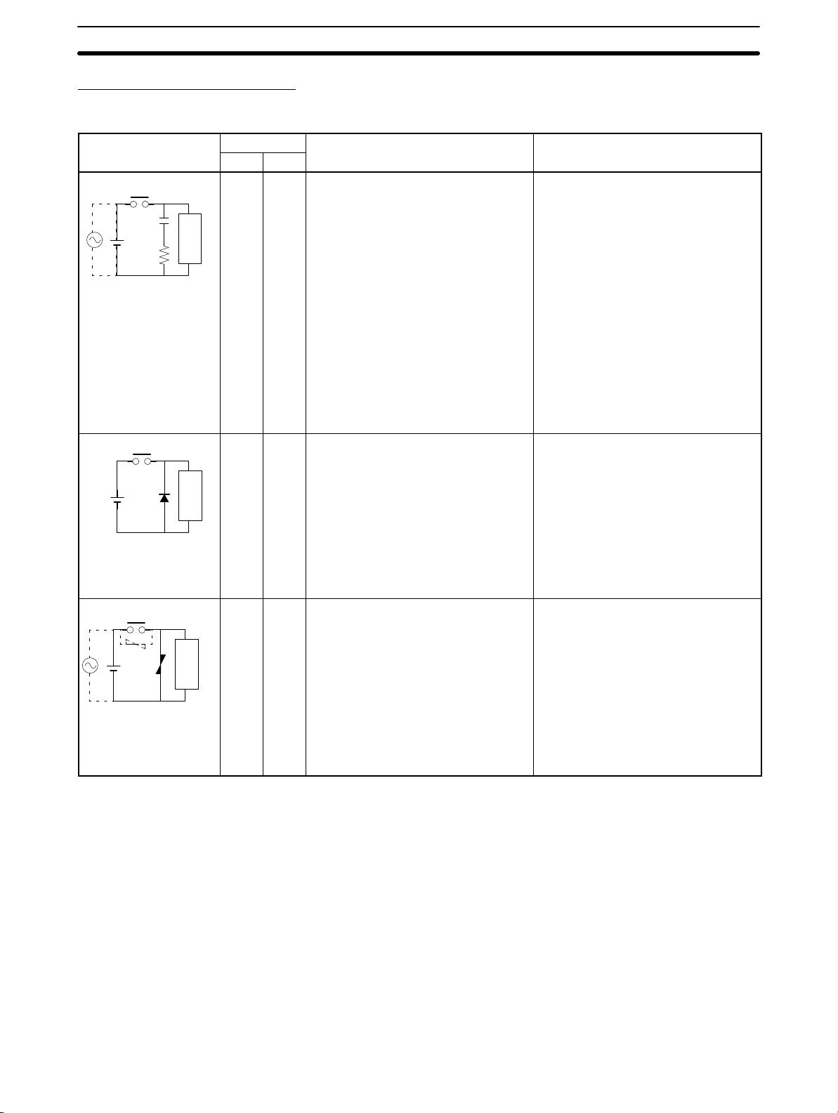
Countermeasure Examples
When switching an inductive load, connect a surge protector, diodes, etc., in parallel with the load or contact as shown below.
Circuit Current Characteristic Required element
AC DC
CR method
Power
supply
Diode method
Power
supply
Varistor method
Power
supply
Yes Yes If the load is a relay or solenoid, there
Inductive
load
No Yes The diode connected in parallel with
Inductive
load
Yes Yes The varistor method prevents the
Inductive
load
is a time lag between the moment the
circuit is opened and the moment the
load is reset.
If the supply voltage is 24 to 48 V,
insert the surge protector in parallel
with the load. If the supply voltage is
100 to 200 V, insert the surge
protector between the contacts.
the load changes energy accumulated
by the coil into a current, which then
flows into the coil so that the current
will be converted into Joule heat by
the resistance of the inductive load.
This time lag, between the moment
the circuit is opened and the moment
the load is reset, caused by this
method is longer than that caused by
the CR method.
imposition of high voltage between the
contacts by using the constant voltage
characteristic of the varistor. There is
time lag between the moment the
circuit is opened and the moment the
load is reset.
If the supply voltage is 24 to 48 V,
insert the varistor in parallel with the
load. If the supply voltage is 100 to
200 V, insert the varistor between the
contacts.
6EC Directives
The capacitance of the capacitor must
be 1 to 0.5 µF per contact current of
1 A and resistance of the resistor must
be 0.5 to 1 Ω per contact voltage of
1 V. These values, however, vary with
the load and the characteristics of the
relay. Decide these values from
experiments, and take into
consideration that the capacitance
suppresses spark discharge when the
contacts are separated and the
resistance limits the current that flows
into the load when the circuit is closed
again.
The dielectric strength of the capacitor
must be 200 to 300 V. If the circuit is
an AC circuit, use a capacitor with no
polarity.
The reversed dielectric strength value
of the diode must be at least 10 times
as large as the circuit voltage value.
The forward current of the diode must
be the same as or larger than the load
current.
The reversed dielectric strength value
of the diode may be two to three times
larger than the supply voltage if the
surge protector is applied to electronic
circuits with low circuit voltages.
—
xxii

CPM2A 24
—VDC CPU Unit Conformance to NK Standards
6-5 CPM1A-MAD01 Conformance to EMC Directives
Immunity testing conditions when using the current I/O of the CPM1A-MAD01
are as follows.
• Total accuracy: +10%/-1%
• Insert the following core in each line as shown below.
Recommended core: 2643-002402
Manufacturer: Fair Rite Products Corp.
7
7 CPM2A 24—VDC CPU Unit Conformance to NK Standards
Surge immunity testing conditions when using a 24-VDC CPU Unit of the
CPM2A are as follows:
• Connect a Transit Voltage Suppressor (TVS) diode between the 24-V and 0-V
DC power supply wiring. The polarity of the TVS diode is bidirectional, i.e., it
has no set polarity.
Recommended TVS: 1.5KE33CA
Manufacturer: Vishay Semiconductors (formerly General Semiconductors)
ST Microelectronics K.K.
xxiii

SECTION 1
Introduction
This section describes the CPM2A’s special features and functions, shows the possible system configurations, and outlines the
steps required before operation. Read this section first when using the CPM2A for the first time.
Refer to the CPM1/CPM1A/CPM2A/CPM2C/SRM1(-V2) Programming Manual (W353) for details on programming opera-
tion.
1-1 CPM2A Features and Functions 2. . . . . . . . . . . . . . . . . . . . . . . . . . . . . . . . . . . . . . . . . . . . .
1-1-1 CPM2A Features 2. . . . . . . . . . . . . . . . . . . . . . . . . . . . . . . . . . . . . . . . . . . . . . . . . .
1-1-2 Overview of CPM2A Functions 7. . . . . . . . . . . . . . . . . . . . . . . . . . . . . . . . . . . . . .
1-2 Basic System Configurations 9. . . . . . . . . . . . . . . . . . . . . . . . . . . . . . . . . . . . . . . . . . . . . . . .
1-2-1 Stand-alone CPU Unit 9. . . . . . . . . . . . . . . . . . . . . . . . . . . . . . . . . . . . . . . . . . . . . .
1-2-2 CPU Unit, Expansion Units, and Expansion I/O Units 9. . . . . . . . . . . . . . . . . . . . .
1-3 Structure and Operation 12. . . . . . . . . . . . . . . . . . . . . . . . . . . . . . . . . . . . . . . . . . . . . . . . . . . .
1-3-1 CPU Unit Structure 12. . . . . . . . . . . . . . . . . . . . . . . . . . . . . . . . . . . . . . . . . . . . . . . .
1-3-2 Operating Modes 13. . . . . . . . . . . . . . . . . . . . . . . . . . . . . . . . . . . . . . . . . . . . . . . . . .
1-3-3 Operating Mode at Startup 13. . . . . . . . . . . . . . . . . . . . . . . . . . . . . . . . . . . . . . . . . . .
1-3-4 PC Operation at Startup 14. . . . . . . . . . . . . . . . . . . . . . . . . . . . . . . . . . . . . . . . . . . . .
1-3-5 Cyclic Operation and Interrupts 15. . . . . . . . . . . . . . . . . . . . . . . . . . . . . . . . . . . . . . .
1-4 Functions Listed by Usage 18. . . . . . . . . . . . . . . . . . . . . . . . . . . . . . . . . . . . . . . . . . . . . . . . . .
1-5 Comparison with the CPM1A 21. . . . . . . . . . . . . . . . . . . . . . . . . . . . . . . . . . . . . . . . . . . . . . .
1-6 Preparation for Operation 26. . . . . . . . . . . . . . . . . . . . . . . . . . . . . . . . . . . . . . . . . . . . . . . . . . .
1

1-1 CPM2A Features and Functions
1-1-1 CPM2A Features
The CPM2A PCs incorporate a variety of features in a compact Unit, including
synchronized pulse control, interrupt inputs, pulse outputs, analog settings, and
a clock function. Also, the CPM2A CPU Unit is a stand-alone Unit that can handle a broad range of machine control applications, so it is ideal for use as a builtin control unit in equipment.
The full complement of communications functions provide communications with
personal computers, other OMRON PCs, and OMRON Programmable Terminals. These communications capabilities allow the user to design a low-cost distributed production system.
1-1SectionCPM2A Features and Functions
The CPU Unit contains 20, 30, 40, or 60 I/O points and
Expansion I/O Units can be added to provide a total I/O
capacity of up to 120 I/O points. Analog I/O Units, Temperature Sensor Units, CompoBus/S I/O Link Units, and
DeviceNet I/O Link Units can also be connected.
Basic Functions
CPU Unit Variations
Expansion I/O Units
2
Peripheral Port
Programming Devices are compatible with
other models of OMRON PCs. This port
can also be used for Host Link or no-protocol communications.
The CPM2A PCs are one-piece PCs with 20, 30, 40, or 60 built-in I/O terminals.
There are 3 types of outputs available (relay outputs, sinking transistor outputs,
and sourcing transistor outputs) and 2 types of power supplies available
(100/240 VAC or 24 VDC).
Up to 3 Expansion I/O Units can be connected to the CPU Unit to increase the
PC’s I/O capacity to a maximum of 120 I/O points. There are 3 types of Expansion I/O Units available: a 20-point I/O Unit, an 8-point Input Unit, and an 8-point
Output Unit. The maximum I/O capacity of 120 I/O points is achieved by connecting three 20-point I/O Units to a CPU Unit with 60 built-in I/O terminals.
RS-232C Port
This port can be used for a Host Link,
no-protocol, 1:1 PC Link, or 1:1 NT Link
communications.

1-1SectionCPM2A Features and Functions
Analog I/O Units
Temperature Sensor
Units
Up to 3 Analog I/O Units can be connected to provide analog inputs and outputs.
Each Unit provides 2 analog inputs and 1 analog output, so a maximum of 6 analog inputs and 3 analog outputs can be achieved by connecting 3 Analog I/O
Units.
Unit Analog inputs Analog outputs
CPM1A-MAD01 Signal range: 0 to 10 V, 1 to 5 V, or
4 to 20 mA, Resolution of 1/256
The open-circuit detection function
can be used with the 1 to 5 VDC
and 4 to 20 mA settings.
CPM1A-MAD11 Signal range: 0 to V 5, 0 to 10 V, 1
to 5 V, –10 to 10 V, 0 to 20 mA, or 4
to 20 mA, Resolution of 1/6,000
The open-circuit detection function
can be used with the 1 to 5 VDC
and 4 to 20 mA settings.
Signal range: 0 to 10 V,
–10 to 10 V, or 4 to
20 mA,
Resolution of 1/256
Signal range: 0 to 10 V, 1
to 5 V, –10 to 10 V, 0 to
20 mA, or 4 to 20 mA,
Resolution of 1/6,000
A Temperature Sensor Unit can be connected to provide up to 6 inputs for temperature input from sensors, such as thermocouples or platinum resistance
thermometers.
Temperature Sensor Unit Functions
Thermocouple input (CPM1A-TS001/002; 2/4 input points):
K: –200° to 1,300°C (–300° to 2,300°F)
0.0° to 500.0°C (0.0° to 900.0°F)
J: –100° to 850°C (–100° to 1,500°F)
0.0° to 400.0°C (0.0° to 750.0°F)
Platinum resistance thermometer input (CPM1A-TS101/102; 2/4 input points):
Pt100: –200.0° to 650.0°C (–300.0° to 1,200.0°F)
JPt100: –200.0° to 650.0°C (–300.0° to 1,200.0°F)
CompoBus/S I/O Link
Units
CompoBus/S I/O Link Units can be connected to make the CPM2A a Slave Device in a CompoBus/S Network. The I/O Link Unit has 8 input bits (internal) and
8 output bits (internal).
The CompoBus/S Network provides distributed CPU control based on a “PC +
compact PC” configuration, which is an improvement on the earlier distributed
I/O control based on a “PC + remote I/O” configuration. The distributed CPU
control makes equipment modular, so designs can be standardized, special
needs can be addressed, and modules can be replaced easily in the event of a
breakdown.
CompoBus/S Master Unit
Master PC
(or SRM1 CompoBus/S Master Control Unit)
CPM2A (Slave) CompoBus/S I/O Link Unit
CompoBus/S
Distributed CPU control
DeviceNet I/O Link Units DeviceNet I/O Link Units can be connected to enable using the CPM2A as a De-
viceNet slave. Up to 32 internal input and 32 internal outputs points are supported for each Unit, and up to 3 Units can connected. DeviceNet application
allows networks to be constructed including devices from other manufacturers.
3

1-1SectionCPM2A Features and Functions
Share Programming
Devices
The same Programming Devices, such as Programming Consoles and Support
Software, can be used for the C200H, C200HS, C200HX/HG/HE, CQM1,
CPM1, CPM1A, CPM2C, and SRM1 (-V2) PCs, so existing ladder program resources can be used effectively.
Built-in Motor Control Capability
Synchronized Pulse
Control
(Transistor Outputs Only)
High-speed Counters and
Interrupts
Synchronized pulse control provides an easy way to synchronize the operation
of a peripheral piece of equipment with the main equipment. The output pulse
frequency can be controlled as some multiple of the input pulse frequency, allowing the speed of a peripheral piece of equipment (such as a supply conveyor)
to be synchronized with the speed of the main piece of equipment.
The CPM2A has a total of five high-speed counter inputs. The one high-speed
counter input has a response frequency of 20 kHz/5 kHz and the four interrupt
inputs (in counter mode) have a response frequency of 2 kHz.
The high-speed counter can be used in any one of the four input modes: differential phase mode (5 kHz), pulse plus direction input mode (20 kHz), up/down
pulse mode (20 kHz), or increment mode (20 kHz). Interrupts can be triggered
when the count matches a set value or falls within a specified range.
The interrupt inputs (counter mode) can be used for incrementing counters or
decrementing counters (2 kHz) and trigger an interrupt (executing the interrupt
program) when the count matches the target value.
Encoder
CPM2A
Motor driver Motor
Pulses are output as a fixed multiple of the input frequency.
Easy Position Control
with Pulse Outputs
(Transistor Outputs Only)
CPM2A PCs with transistor outputs have two outputs that can produce 10 Hz to
10 kHz pulses (single-phase outputs).
When used as single-phase pulse outputs, there can be two outputs with a frequency range of 10 Hz to 10 kHz with a fixed duty ratio or 0.1 to 999.9 Hz with a
variable duty ratio (0 to 100% duty ratio).
When used as pulse plus direction or up/down pulse outputs, there can be just
one output with a frequency range of 10 Hz to 10 kHz.
High-speed Input Capabilities for Machine Control
High-speed Interrupt
Input Function
Quick-response Input
Function
Stabilizing Input Filter
Function
There are four inputs used for interrupt inputs (shared with quick-response inputs and interrupt inputs in counter mode) with a minimum input signal width of
50 µs and response time of 0.3 ms. When an interrupt input goes ON, the main
program is stopped and the interrupt program is executed.
There are four inputs used for quick-response inputs (shared with interrupt inputs and interrupt inputs in counter mode) that can reliably read input signals
with a signal width as short as 50 µs.
The input time constant for all inputs can be set to 1 ms, 2 ms, 3 ms, 5 ms,
10 ms, 20 ms, 40 ms, or 80 ms. The effects of chattering and external noise can
be reduced by increasing the input time constant.
Other Functions
Interval Timer Interrupts
The interval timer can be set between 0.5 and 319,968 ms and can be set to generate just one interrupt (one-shot mode) or periodic interrupts (scheduled interrupt mode).
Analog Settings
4
There are two controls on the CPU Unit that can be turned to change the analog
settings (0 to 200 BCD) in IR 250 and IR 251. These controls can be used to eas-

1-1SectionCPM2A Features and Functions
ily change or fine-tune machine settings such as a conveyor belt’s pause time or
feed rate.
Calendar/Clock
The built-in clock (accuracy within 1 minute/month) can be read from the program to show the current year, month, day, day of the week, and time. The clock
can be set from a Programming Device (such as a Programming Console) or the
time can be adjusted by rounding up or down to the nearest minute.
Long-term Timer
TIML(––) is a long-term timer that accommodates set values up to 99,990 seconds (27 hours, 46 minutes, 30 seconds). When combined with the SECONDS
TO HOURS conversion instruction (HMS(––)), the long-term timer provides an
easy way to control equipment scheduling.
Analog PID Control
The PID(––) instruction can be used with an Analog I/O Unit to control analog
I/O.
Complete Communications Capabilities
Host Link
1:1 Host Link Communications
A Host Link connection can be made through the PC’s RS-232C port or Peripheral port. A personal computer or Programmable Terminal (only for 1:1 communications) connected in Host Link mode can be used for operations such as
reading/writing data in the PC’s I/O memory or reading/changing the PC’s operating mode.
1:N Host Link Communications
B500-AL004
Link Adapter
Responses
No-protocol
Communications
Inputting data from
a bar code reader
Bar code reader
Commands
CPM1-CIF01
CPM2A (Peripheral port connection*)
*An RS-232C Adapter is needed
to connect to the Peripheral port.
The TXD(48) and RXD(47) instructions can be used in no-protocol mode to exchange data with standard serial devices. For example, data can be received
from a bar code reader or transmitted to a serial printer. The serial devices can
be connected to the RS-232C port or Peripheral port.
NT-AL001
Responses
Outputting data to
a serial printer
Serial printer
Commands
CPM2A
(RS-232C port connection)
RS-232C/RS-422A Adapter
(Up to 32 PCs can be connected.)
(RS-232C port connection*)
*An RS-232C Adapter is needed to connect to the Peripheral port.
CPM2A
(RS-232C port connection*)
CPM2A
5

1-1SectionCPM2A Features and Functions
High-speed 1:1 NT Link
Communications
One-to-one PC Link
Expansion Memory Unit
In a 1:1 NT Link, an OMRON Programmable Terminal (PT) can be connected
directly to the CPM2A. The PT must be connected to the RS-232C port; it cannot
be connected to the Peripheral port.
OMRON PT
(RS-232C port connection)
CPM2A
A CPM2A can be linked directly to another CPM2A, CQM1, CPM1, CPM1A,
CPM2C, SRM1(-V2), or a C200HS or C200HX/HG/HE PC. The 1:1 PC Link allows automatic data link connections. The PC must be connected through the
RS-232C port; it cannot be connected through the Peripheral port.
(RS-232C port connection)
CPM2A
(RS-232C port connection)
CPM2A
The CPM1-EMU01-V1 Expansion Memory Unit is a program loader for smallsize or micro PLCs. Using the CPM1-EMU01-V1, simple on-site transfer of user
programs and data memory is possible with PLCs.
EEPROM
Uploading
Downloading
SYSMAC
6

1-1-2 Overview of CPM2A Functions
Main function Variations/Details
Interrupts
High-speed counters High-speed counter
Pulse outputs 2 outputs:
Synchronized pulse control 1 point, see notes 2 and 3.
Quick-response input 4 inputs, see note 1.
Analog settings 2 controls (setting ranges: 0 to 200 BCD)
Input time constant Determines the input time constant for all inputs. (Settings: 1, 2, 3, 5, 10, 20, 40, or 80 ms)
Calendar/Clock Shows the current year, month, day of the week, day of the month, hour, minute, and
Interrupt inputs
4 inputs, see note 1.
Response time: 0.3 ms
Interval timer interrupts
1 input
Set value: 0.5 to 319,968 ms
Precision: 0.1 ms
nput, see note 2.
Differential phase mode (5 kHz)
Pulse plus direction input mode (20 kHz)
Up/down input mode (20 kHz)
Increment mode (20 kHz)
Interrupt inputs (counter mode)
4 inputs, see note 1.
Incrementing counter (2 kHz)
Decrementing counter (2 kHz)
Single-phase pulse output without acceleration/deceleration (See note 3.)
10 Hz to 10 kHz
2 outputs:
Variable duty ratio pulse output (See note 3.)
0.1 to 999.9 Hz, duty ratio 0 to 100%
1 output:
Pulse output with trapezoidal acceleration/deceleration (See note 3.)
Pulse plus direction output, up/down pulse output, 10 Hz to 10 kHz
Input frequency range: 10 to 500 Hz, 20 Hz to 1 kHz, or 300 Hz to 20 kHz
Output frequency range: 10 Hz to 10 kHz
Minimum input signal width: 50 µs
second.
Scheduled interrupts
One-shot interrupt
No interrupt
Count-check interrupt
(An interrupt can be generated when the
count equals the set value or the count
lies within a preset range.)
No interrupt
Count-up interrupt
1-1SectionCPM2A Features and Functions
7

Main function Variations/Details
Expansion Unit functions
Analog I/O Unit functions (CPM1A-MAD01) (resolution: 1/256)
Two analog inputs: input range 0 to 10 V, 1 to 5 V, or 4 to 20 mA
One analog output: output range 0 to 10 V, –10 to 10 V, or 4 to 20 mA
Analog I/O Unit functions (CPM1A-MAD11) (resolution: 1/6000)
Two analog inputs: input range 0 to 5 V, 1 to 5 V, 0 to 10 V, –10 to 10 V, 0 to 20 mA, or
4 to 20 mA
One analog output: output range 1 to 5 V, 0 to 10 V, –10 to 10 V, 0 to 20 mA, or 4 to
20 mA
Temperature Sensor Unit functions
Thermocouple input (CPM1A-TS001/002; 2/4 input points):
K: –200° to 1,300°C (–300° to 2,300°F)
0.0° to 500.0°C (0.0° to 900.0°F)
J: –100° to 850°C (–100° to 1,500°F)
0.0° to 400.0°C (0.0° to 750.0°F)
Platinum resistance thermometer input (CPM1A-TS101/102; 2/4 input points):
Pt100: –200.0° to 650.0°C (–300.0° to 1,200.0°F)
JPt100: –200.0° to 650.0°C (–300.0° to 1,200.0°F)
CompoBus/S Slave functions (CPM1A-SRT21)
Exchanges 8 input bits and 8 output bits of data with the Master Unit.
DeviceNet Slave functions
Exchanges 32 input bits and 32 output bits of data with the DeviceNet Master Unit.
1-1SectionCPM2A Features and Functions
Note 1. These four inputs are shared by interrupt inputs, interrupt inputs in counter
mode, and quick-response inputs, but each input can be used for only one
purpose.
2. This input is shared by the high-speed counter and synchronized pulse control functions.
3. This output is shared by the pulse output and synchronized pulse control
functions. These functions can be used with transistor outputs only.
8

1-2 Basic System Configurations
1-2-1 Stand-alone CPU Unit
CPU Unit with 20/30 I/O Points CPU Unit with 40 I/O Points CPU Unit with 60 I/O Points
Number of I/O points Power supply Inputs Outputs Model
20 I/O points
(12 inputs and 8 outputs)
30 I/O points
(18 inputs and 12 outputs)
40 I/O points
(24 inputs and 16 outputs)
60 I/O points
(36 inputs and 24 outputs)
100 to 240 VAC 24 VDC Relay CPM2A-20CDR-A
24 VDC
100 to 240 VAC 24 VDC Relay CPM2A-30CDR-A
24 VDC
100 to 240 VAC 24 VDC Relay CPM2A-40CDR-A
24 VDC
100 to 240 VAC 24 VDC Relay CPM2A-60CDR-A
24 VDC
24 VDC Relay CPM2A-20CDR-D
24 VDC Sinking Transistor CPM2A-20CDT-D
24 VDC Sourcing Transistor CPM2A-20CDT1-D
24 VDC Relay CPM2A-30CDR-D
24 VDC Sinking Transistor CPM2A-30CDT-D
24 VDC Sourcing Transistor CPM2A-30CDT1-D
24 VDC Relay CPM2A-40CDR-D
24 VDC Sinking Transistor CPM2A-40CDT-D
24 VDC Sourcing Transistor CPM2A-40CDT1-D
24 VDC Relay CPM2A-60CDR-D
24 VDC Sinking Transistor CPM2A-60CDT-D
24 VDC Sourcing Transistor CPM2A-60CDT1-D
1-2SectionBasic System Configurations
1-2-2 CPU Unit, Expansion Units, and Expansion I/O Units
Up to 3 Expansion Units or Expansion I/O Units can be connected to the expansion connector with expansion I/O connecting cables. (Only one Expansion Unit
or Expansion I/O Unit can be connected if an NT-AL001 Adapter is connected to
the RS-232C port because the CPU Unit’s 5-VDC power supply is limited.)
There are four types of Units available: Expansion I/O Units, an Analog I/O Unit,
Temperature Sensor Units, a CompoBus/S I/O Link Unit, and a DeviceNet I/O
Link Unit.
Expansion connector
Expansion I/O Unit or Expansion Unit
(Analog I/O Unit, Temperature Sensor
Unit, CompoBus/S I/O Link Unit, or
DeviceNet I/O Link Unit)
Expansion I/O connecting cable
A PC with 120 I/O points (the maximum) can be assembled by connecting three
Expansion I/O Units to a CPU Unit with 60 I/O points.
CPM2A-60CDR-A
(36 inputs, 24 outputs)
× 1 Unit + × 3 Units = 72 inputs, 48 outputs
CPM1A-20EDR1
(12 inputs, 8 outputs)
9

1-2SectionBasic System Configurations
A PC with 6 analog inputs and 3 analog outputs (the maximum) can be assembled by connecting three Analog I/O Units. (Only one Analog I/O Unit can be
connected if an NT-AL001 Adapter is connected to the CPU Unit’s RS-232C
port.)
A PC with up to 6 temperature inputs for input from thermocouples or platinum
resistance thermometers can be assembled by connecting Temperature Sensor
Units.
CompoBus/S I/O Link Units (Slave Units) can be connected to a CPU Unit. I/O
data (8 inputs and 8 outputs) is transferred between the CPU Unit and the area
allocated to the CompoBus/S Slave. (The I/O data exchanged with the Slave is
internal data; there are no external input or output terminals.)
DeviceNet I/O Link Units can be connected to a CPU Unit. I/O data (32 inputs
and 32 outputs) is transferred between the CPU Unit and the area allocated to
the DeviceNet I/O Link Unit. (The I/O data exchanged with the Slave is internal
data; there are no external input or output terminals.)
Note 1. Different types of Expansion I/O Units or Expansion Units can be connected
at the same time. For example, an Expansion I/O Unit, an Analog I/O Unit, a
CompoBus/S I/O Link Unit, and DeviceNet I/O Link Unit can be connected to
the CPU Unit.
Expansion I/O Units
Unit Max. number
Expansion
I/O Units points
20 I/O
8 outputs
8 inputs 24 VDC — CPM1A-8ED
8 outputs
2. When an NT-AL001 Adapter is connected to the RS-232C port, only one Ex-
of Units
3 Units max.
ee note.
pansion Unit or Expansion I/O Unit can be connected to the CPU Unit because of power supply limitations.
8-point Input Unit 8-point Output Unit20-point I/O Unit
Inputs Outputs Model
24 VDC Relays CPM1A-20EDR1
24 VDC Sinking transistors CPM1A-20EDT
24 VDC Sourcing transistors CPM1A-20EDT1
— Relays CPM1A-8ER
— Sinking Transistors CPM1A-8ET
— Sourcing Transistors CPM1A-8ET1
Note Only one Expansion I/O Unit can be connected if an NT-AL001 Adapter is con-
nected to the CPU Unit’s RS-232C port.
10

Expansion Units
CPM1A-MAD01
Analog I/O Unit
CPM1A-MAD11
Analog I/O Unit
1-2SectionBasic System Configurations
Temperature Sensor Unit
CompoBus/S I/O
Link Unit
Unit Max. number
Analog I/O Unit
2 analog inputs (2 words)
1 analog output (1 word)
Temperature
Sensor Unit
CompoBus/S I/O Link Unit
8 inputs and 8 outputs
DeviceNet I/O Link Unit
32 inputs and 32 outputs
Thermocouple
inputs
Platinum
resistance
thermometer
inputs
DeviceNet I/O
Link Unit
Inputs Outputs Model
of Units
3 Units max.
(See note.)
3 Units max.
(See note.)
1 Unit max. 4 inputs (K, J) CPM1A-TS002
3 Units max.
(See note.)
1 Unit max. 4 inputs (Pt100, JPt100) CPM1A-TS102
3 Units max.
(See note.)
3 Units max.
(See note.)
2 analog inputs 1 analog output CPM1A-MAD01
CPM1A-MAD11
2 inputs (K, J)
2 inputs (Pt100, JPt100) CPM1A-TS101
8 bits
(Inputs from the Master.)
32 bits
(Inputs from the Master.)
—
8 bits
(Outputs to the Master.)
32 bits
(Outputs to the Master.)
CPM1A-TS001
CPM1A-SRT21
CPM1A-DRT21
Note 1. Only one CPM1A-TS002/TS102 Temperature Sensor Unit can be con-
nected to the CPU Unit. If a CPM1A-TS002/102 is connected to the CPU
Unit, only one additional Expansion Unit (other than a CPM1A-TS002/102)
or one Expansion I/O Unit can be connected to the CPU Unit.
2. Only one Expansion Unit can be connected if an NT-AL001 Adapter is connected to the CPU Unit’s RS-232C port.
11

1-3 Structure and Operation
1-3-1 CPU Unit Structure
The following diagram shows the internal structure of the CPU Unit.
I/O memory
1-3SectionStructure and Operation
I/O Memory
Program
External
input
devices
External
output
devices
Input circuits
Peripheral
port
Program
Settings
Communications
processing
Settings
Settings
Communications switch
PC Setup
Output circuits
RS-232C
port
The program reads and writes data in this memory area during execution. Part of
the I/O memory contains the bits that reflect the status of the PC’s inputs and
outputs. Parts of the I/O memory are cleared when the power is turned ON and
other parts are retained.
Note Refer to Section 3 Memory Areas in the Programming Manual (W353) for more
details on I/O memory.
This is the program written by the user. The CPM2A executes the program cyclically. (Refer to 1-3-5 Cyclic Operation and Interrupts for details.)
The program can be divided broadly into two parts: the “main program” that is
executed cyclically and the “interrupt programs” that are executed only when the
corresponding interrupt is generated.
PC Setup
Communications Switch
12
The PC Setup contains various startup and operating parameters. The PC Setup parameters can be changed from a Programming Device only; they cannot
be changed from the program.
Some parameters are accessed only when PC’s power supply is turned on and
others are accessed regularly while the power is on. It will be necessary to turn
the power off and then on again to enable a new setting if the parameter is accessed only when the power is turned on.
Note Refer to Section 1 PC Setup in the Programming Manual (W353) for more de-
tails.
The Communications Switch determines whether the peripheral port and
RS-232C port operate with the standard communications settings or the communications settings in the PC Setup.

1-3-2 Operating Modes
CPM2A CPU Units have 3 operating modes: PROGRAM, MONITOR, and RUN.
1-3SectionStructure and Operation
PROGRAM Mode
MONITOR Mode
RUN Mode
The program cannot be executed in PROGRAM mode. This mode is used to
perform the following operations in preparation for program execution
• Changing initial/operating parameters such as those in the PC Setup
• Writing, transferring, or checking the program
• Checking wiring by force-setting and force-resetting I/O bits
The program is executed in MONITOR mode and the following operations can
be performed from a Programming Device. In general, MONITOR mode is used
to debug the program, test operation, and make adjustments.
• Online editing
• Monitoring I/O memory during operation
• Force-setting/force-resetting I/O bits, changing set values, and changing pres-
ent values during operation
The program is executed at normal speed in RUN mode. Operations such as
online editing, force-setting/force-resetting I/O bits, and changing set values/
present values cannot be performed in RUN mode, but the status of I/O bits can
be monitored.
Note When the PC is in RUN mode with a Programming Console connected to the
peripheral port, if a PT is connected to the RS-232C port via Host Link, the Programming Console will display a message prompting the user to enter a password. (For details, refer to page 85.) This is because, in order to write data to the
PC, the PT automatically switches the operating mode from RUN mode to MONITOR mode.
• This automatic mode change will not be performed if the PT is connected via
NT Link.
• When a Programming Device installed on a computer is connected to the
peripheral port, the display (at the computer) for the CPU Unit’s operating
mode will simply change from “RUN” to “MONITOR.”
1-3-3 Operating Mode at Startup
The operating mode of the CPM2A when the power is turned on depends upon
the PC Setup settings and the Programming Console’s mode switch setting if a
Programming Console is connected.
PC Setup setting
Word Bits Setting
DM6600 08 to 15
00 to 07
Note The default setting is 00. With this default setting, the startup operating mode is
determined by the Programming Console’s mode switch setting if a Programming Console is connected to the Peripheral port. If a Programming Console is
not connected, the PC will automatically enter RUN mode.
Programming Console
connected
00 Startup mode determined
by the mode switch
setting.
01 Startup mode is the same as the operating mode
before power was interrupted.
02 Startup mode is determined by bits 00 to 07.
00 PROGRAM mode
01 MONITOR mode
02 RUN mode
Programming Console
not connected
Startup mode is RUN
mode. (See note.)
13

1-3-4 PC Operation at Startup
1-3SectionStructure and Operation
Time Required for
Initialization
Power OFF Operation
The time required for startup initialization depends on several factors, such as
the operating conditions (including power supply voltage, system configuration,
and ambient temperature) and the program contents.
Minimum Power Supply Voltage
The PC will stop and all outputs will be turned OFF if the power supply voltage
falls below 85% of the rated value.
Momentary Power Interruption
A power interruption will not be detected and CPU Unit operation will continue if
the power interruption lasts less than 10 ms for an AC power supply or 2 ms for a
DC power supply.
A power interruption may or may not be detected for power interruptions somewhat longer than 10 ms for an AC power supply or 2 ms for a DC power supply.
When a power interruption is detected, the CPU Unit will stop operating and all
outputs will be turned OFF.
Automatic Reset
Operation will restart automatically when the power supply voltage is restored to
more than 85% of the rated voltage.
Timing Chart of Power OFF Operation
The power interruption detection time is the time required for a power interruption to be detected after the power supply voltage drops below 85% of the rated
value.
1, 2, 3… 1. Minimum power interruption detection time
Power interruptions that are shorter than 10 ms (AC power supply) or 2 ms
(DC power supply) will not be detected.
2. Undetermined additional time
Power interruptions only slightly longer than the minimum power interruption time may not be detected.
85% of rated voltage
Detection of
power interruption
2. Additional
time
CPU Unit operation may
continue if voltage is
restored in this region.
Program execution
CPU reset signal
1. Minimum time
Executing Stopped
CPU Unit operation will
continue if voltage is
restored in this region.
Note If the power supply voltage fluctuates around 85% of the PC’s rated voltage, PC
operation may stop and restart repeatedly. When repeated stopping and starting
will cause problems with the controlled system, set up a protective circuit such
as a circuit that shuts off the power supply to sensitive equipment until the power
supply voltage returns to the rated value.
14

1-3-5 Cyclic Operation and Interrupts
1-3SectionStructure and Operation
Basic CPU Operation
Initialization processing is performed when the power is turned on. If there are no
initialization errors, the overseeing processes, program execution, I/O refreshing, and communications port servicing are performed repeatedly (cyclically).
S Check hardware.
Startup initialization
Overseeing
processes
Program execution
S Check memory.
S Read data from flash memory (program,
read-only DM data, and PC Setup settings).
S Check for battery error.
S Preset the watch (maximum) cycle time.
S Check program memory.
S Refresh bits for expansion functions.
S Execute the program.
(Refer to the Programming Manual (W353) for
details on cycle time and I/O response times.)
S Wait for minimum cycle time if a minimum
Cycle time
PC cycle time
calculation
I/O refreshing
RS-232C port
servicing
Peripheral port
servicing
cycle time has been set in the PC Setup
(DM 6619).
S Calculate cycle time.
S Read input data from input bits.
S Write output data to output bits.
S Perform RS-232C port communications
processing. (Can be changed in DM 6616.)
S Perform Peripheral port communications
processing. (Can be changed in DM 6617.)
The cycle time can be read from a Programming Device.
AR 14 contains the maximum cycle time and AR 15 contains the present cycle
time in multiples of 0.1 ms.
15

1-3SectionStructure and Operation
The cycle time will vary slightly depending on the processing being performed in
each cycle, so the calculated cycle time will not always match the actual cycle
time.
Program Execution in
Cyclic Operation
The following diagram shows the cyclic operation of the CPM2A when the program is being executed normally.
Normally, the results of program execution are transferred to I/O memory just
after program execution (during I/O refreshing), but IORF(97) can be used to refresh a specified range of I/O words during program execution. The specified
range of I/O words will be refreshed when IORF(97) is executed.
The cycle time is the sum of the time required for program execution, I/O refreshing, and communications port servicing.
A minimum cycle time (1 to 9,999 ms) can be set in the PC Setup (DM 6619).
When a minimum cycle time has been set, CPU operation is paused after program execution until the minimum cycle time is reached. CPU operation will not
be paused if the actual cycle time is longer than the minimum cycle time set in
DM 6619.
Note A fatal error will occur and PC operation will stop if a maximum cycle time has
been set in the PC Setup (DM 6618) and the actual cycle time exceeds that setting.
The default settings for RS-232C port servicing and Peripheral port servicing are
5% of the cycle time, but these settings can be changed (between 1% and 99%)
in the PC Setup. The RS-232C port’s setting is in DM 6616 and the Peripheral
port’s setting is in DM 6617.
Refer to Section 7 PC Operations and Processing Time in the Programming
Manual (W353) for more details and precautions on the cycle time.
Cycle
time
Overseeing processes
Main program
I/O refreshing
RS-232C port servicing
Peripheral port servicing
If a minimum cycle time has been
set in DM 6619, CPU operation is
paused until the minimum cycle
time is reached.
The servicing time can be set
in DM 6616.
The servicing time can be set
in DM 6617.
16

1-3SectionStructure and Operation
Interrupt Program
Execution
When an interrupt is generated during execution of the main program, main program execution is interrupted immediately and the interrupt program is executed. The following diagram shows the cyclic operation of the CPM2A when an
interrupt program is executed.
Normally, the results of interrupt program execution are transferred to I/O
memory just after program execution (during I/O refreshing), but IORF(97) can
be used to refresh a specified range of I/O words during execution of the interrupt program. The specified range of I/O words will be refreshed when IORF(97)
is executed.
The normal cycle time is extended by the time required for execution of the interrupt program.
Refer to Section 7 PC Operations and Processing Time in the Programming
Manual (W353) for more details and precautions on the cycle time.
Overseeing processes
Main program
Interrupt generated.
Interrupt program
Cycle
time
I/O refreshing
RS-232C port servicing
Peripheral port servicing
Caution Although IORF(97) can be used in interrupt subroutines, you must be careful of
!
the interval between IORF(97) executions. If IORF(97) is executed too frequently, a fatal system error may occur (FALS 9F), stopping operation. The interval
between executions of IORF(97) should be at least 1.3 ms + total execution time
of the interrupt subroutine.
Immediate Refreshing
IORF(97) can be executed in the program to refresh a specified range of I/O
words. The specified I/O words will be refreshed when IORF(97) is executed.
IORF(97) can be used to refresh I/O from the main program or the interrupt program.
17

1-4SectionFunctions Listed by Usage
When IORF(97) is used, the cycle time is extended by the time required to refresh the specified I/O words.
Overseeing processes
Main program
IORF(97) executed.
Cycle
time
I/O refreshing
RS-232C port servicing
Peripheral port servicing
1-4 Functions Listed by Usage
Immediate refreshing
I/O refreshing
Machine Control Functions
Receive high-speed
count inputs
(For example, calculating
length or position with an
encoder).
Generate a pulse output based on a multiple of an input pulse to
synchronize control of a peripheral process with the main process.
The multiple for the peripheral process (such as tool feed rate) can be
changed during operation by calculating the multiple from another input
value (such as an encoder) in the peripheral process.
This method can be used to change the process for different products
or models without stopping the equipment.
18
Usage Function Refer
Max. count frequency of 2 kHz
(single-phase)
Max. count frequency of 5 kHz (differential
phase) or 20 kHz (single-phase)
Use interrupt input (counter mode) to
read the present value without
interrupts.
Use high-speed counter to read the
present value without interrupts.
Pulse synchronization
to
W353

1-4SectionFunctions Listed by Usage
Usage Refer
Multiply the input pulse frequency from a high-speed counter by a fixed
multiple, convert that value to an analog value, and output as an
analog output.
(For example, synchronizing the speed of a supply conveyor with the
rotational position of the main piece of equipment (such as a label
inserter) measured by an analog input.)
Reliably receive input pulses with an ON-time shorter than the cycle
time (such as inputs from a photomicrosensor).
Interrupt functions
Perform simple positioning by outputting pulses to a motor driver that
accepts pulse-train inputs.
Use a variable duty-ratio output to perform time-allocated temperature
control.
Easily set and fine-tune settings such as the low-speed feed rate when
a conveyor is temporarily stopped.
Receive an analog input and output an analog output. Analog I/O Unit
Receive temperature sensor input directly at the PC. Temperature Sensor Unit
Reduce required wiring, space, and PC load by controlling equipment
with a few low-capacity PCs dispersed near the equipment rather than
a single, large, centralized PC.
(Create a remote I/O link with a CompoBus/S Master and CompoBus/S
Slaves.)
Execute a special process very quickly
when an input goes ON.
(For example, operating a cutter when an
interrupt input is received from a Proximity
Switch or Photoelectric Switch.)
Count input ON pulses and execute a
special process very quickly when the
count reaches the preset value.
(For example, stopping the supply feed
when a preset number of workpieces have
passed through the system.)
Execute a special process at a preset
count value.
(For example, cutting material very
precisely at a given length.)
Execute a special process when the count
is within a preset range.
(For example, sorting material very quickly
when it is within a given length range.)
Execute a special process when a timer
times out.
(For example, stopping a conveyor at very
precise time (independent of the cycle
time) after the workpiece is detected.)
Repeat a special process at regular
intervals.
(For example, the speed of a sheet feeder
can be monitored by measuring the input
signal from an encoder at regular intervals
and calculating the speed.)
Pulse synchronization and analog
output function
Quick-response input function
Interrupt input (interrupt input mode)
Interrupt input (counter mode)
High-speed counter interrupt
generated when the count matches
the set value.
High-speed counter interrupt
generated when the count is within the
set range.
Interval timer interrupt
(One-shot mode)
Interval timer interrupt
(Scheduled interrupt mode)
Pulse output function
Analog input + Variable duty-ratio
output pulse function (PWM(––))
Analog controls
(Connect the Analog I/O Unit to the
CPU Unit.)
(Connect the Temperature Sensor
Unit to the CPU Unit.)
CompoBus/S I/O Link Unit
(Connect the CompoBus/S I/O Link
Unit to the CPU Unit.)
Function
to
W353
19

Basic Functions
Usage Function Refer
Set the cycle time to a fixed interval. Set a minimum (fixed) cycle time in the PC Setup.
Stop PC operation when the cycle time exceeds a
maximum setting.
Keep all outputs ON when PC operation stops. Turn ON the IOM Hold Bit (SR 25212).
Retain the contents of I/O memory when starting
operation.
Retain the contents of I/O memory when the PC is
turned on.
Eliminate effects from chattering and external noise. Set a longer input time constant in the PC Setup.
Set a maximum (watch) cycle time in the PC Setup.
Turn ON the IOM Hold Bit (SR 25212).
Turn ON the IOM Hold Bit (SR 25212) and set the PC
Setup (DM 6601) so that the status of the IOM Hold Bit
is maintained at startup.
Maintenance Functions
Usage Function Refer
Record data with time-stamp. Clock/calendar function
Establish user-defined errors for desired input
conditions. (Fatal and non-fatal errors can be defined.)
Read the number of power interruptions. The number of power interruptions is stored in AR 23.
Set the startup operating mode. Set the startup operating mode in the PC Setup
FAL(06) defines non-fatal errors. (PC operation
continues.)
FALS(07) defines fatal errors. (PC operation stops.)
(DM 6600).
1-4SectionFunctions Listed by Usage
to
W353
to
W353
Communications Functions
Usage Function Refer
to
Read/write I/O memory data and change the operating
mode from a host computer.
Connect to a serial device such as a bar code reader
or serial printer.
Make a high-speed connection with an OMRON
Programmable Terminal.
Make a PC-PC data link connection with another
CPM2A, or a CPM1, CPM1A, CPM2C, SRM1, CQM1,
C200HS, or C200HX/HG/HE PC.
Connect a Programming Console. Connect the Programming Console to the Peripheral
Connect a personal computer running
CX-Programmer, SYSMAC Support Software (SSS) or
SYSMAC-CPT Support Software.
Monitor equipment with a Programmable Terminal and
program the PC with a Programming Device.
Reduce both resources and space by using remote
I/O.
Creating a link with a DeviceNet Master. Use a DeviceNet Link Unit. W353
Host Link communications (Set the communications
mode to Host Link in the PC Setup.)
No-protocol communications (Set the communications
mode to no-protocol in the PC Setup.)
1:1 NT Link (Set the communications mode to 1:1 NT
Link in the PC Setup.)
1:1 PC Link (Set the communications mode to 1:1 PC
Link in the PC Setup.)
port. (The CPU Unit’s Communications Switch setting
has no effect on this connection.)
The computer can be connected to the Peripheral port
or RS-232C port.
(The Host Link settings in the PC Setup are used
when the switch is OFF; the standard Host Link
communications settings are used when the CPU
Unit’s Communications Switch is ON.)
The RS-232C port and Peripheral port can be used
simultaneously.
Use a CompoBus/S Link Unit. W353
W353
Page
93
W353
Page
81
W353
Page
93
Page
43
Page
44
20

1-5 Comparison with the CPM1A
Item CPM2A CPM1A
Instruction set
Instruction
execution times
Program capacity 4,096 words 2,048 words
Maximum number
of I/O points
Expansion Units
and Expansion I/O
Units
I/O memory
Memory backup
Interrupt inputs (interrupt input mode) 4 Same as CPM2A.
Interrupt inputs
(counter mode)
Basic instructions 14 Same as CPM2A.
Special instructions 105 instructions, 185 variations 79 instructions, 139 variations
Basic instructions LD: 0.64 µs LD: 1.72 µs
Special instructions MOV(21): 7.8 µs MOV(21): 16.3 µs
Stand-alone CPU Unit 30, 40, or 60 points 10, 20, 30, or 40 points
CPU Unit with Expansion I/O
Units
Maximum number of Units A maximum of 3 Units can be
Available models Expansion I/O Units,
Input bits IR 00000 to IR 00915 Same as CPM2A.
Output bits IR 01000 to IR 01915 Same as CPM2A.
Work bits 928 bits:
SR (Special Relay) area 448 bits:
TR (Temporary Relay) area 8 bits: TR0 to TR7 Same as CPM2A.
HR (Holding Relay) area 320 bits:
AR (Auxiliary Relay) area 384 bits:
LR (Link Relay) area 256 bits:
Timer/Counter area 256 bits:
DM (Data
Memory) area
Program area, read-only DM
area (including PC Setup)
Read/write DM area, HR area,
AR area, and counters
Counter mode Incrementing counter
Counter upper limit 2 kHz 1 kHz
SR 244 to SR 247 Contains counter PV. Contains counter PV–1.
Method(s) to read counter PV Read SR 244 to SR 247.
Method to change counter PV Execute INI(61). Not supported.
Read/write
area
Read-only
area
PC Setup 56 words
90, 100, or 120 points max. 90 or 100 points max.
A maximum of 3 Units can be
connected to any of the CPU
Units.
(If the CPM1A-TS002/102 is
connected, the maximum is 2.)
Analog I/O Unit, Temperature
Sensor Units, CompoBus/S I/O
Link Unit, and DeviceNet I/O
Link Unit
IR 02000 to IR 04915,
IR 20000 to IR 22715
SR 22800 to SR 25515
HR 0000 to HR 1915
AR 0000 to AR 2315
LR 0000 to LR 1515
TIM/CNT 0 to TIM/CNT 256
2,048 words
(DM 0000 to DM 2047)
456 words
(DM 6144 to DM 6599)
(DM 6600 to DM 6655)
Flash memory backup Same as CPM2A.
Internal battery backup
(5-year lifetime, replaceable)
Decrementing counter
Execute PRV(62).
(Counter PV)
connected to the 30-point and
40-point CPU Units.
Same as CPM2A.
512 bits:
IR 20000 to IR 23115
384 bits:
SR 23200 to SR 25515
Same as CPM2A.
256 bits:
AR 0000 to AR 1515
Same as CPM2A.
128 bits:
TIM/CNT 0 to TIM/CNT 127
1,024 words
(DM 0000 to DM 1023)
Same as CPM2A.
Same as CPM2A.
Capacitor backup
(20-day backup at 25°C)
Decrementing counter
Read SR 244 to SR 247.
(Counter PV – 1)
1-5SectionComparison with the CPM1A
21

Item CPM1ACPM2A
Interval timer
Quick-response
inputs
High-speed
counter
Pulse synchronization Supported. Not supported.
One-shot mode Yes Yes
Scheduled interrupt mode Ye s Yes
Setting the quick-response
function
INT(89) (Mask) Not supported (ignored) Supported.
INT(89) (Read mask) Reads mask status. Reads result of mask setting.
INT(89) (Clear) Not supported (ignored) Supported.
Minimum pulse width 50 µs min. 200 µs min.
Count mode Differential-phase (up/down)
Max. counter frequency 5 kHz in differential-phase
Counter PV range –8,388,608 to 8,388,607 in
Check when registering target
value match table
Method used to reference the
target value match interrupt
table
Reading range-comparison
results
Reading status Check AR 1108 (comparison in
PC Setup PC Setup and INT(89)
(Unmask interrupt input.)
Differential-phase (up/down)
mode
Pulse plus direction mode
Up/down pulse mode
Increment mode
(up/down) mode
20 kHz in pulse plus direction
mode, up/down pulse mode,
and increment mode
differential-phase (up/down)
mode, pulse plus direction
mode, and up/down pulse
mode
0 to 16,777,215 in increment
mode
Same direction, same SV not
possible
Comparison of all values in the
table, regardless of order of
appearance in table
Check AR 1100 to AR 1107 or
execute PRV(62).
progress), check AR 1109
(high-speed counter PV
overflow/underflow), or
execute PRV(62).
mode
Increment mode
2.5 kHz in differential-phase
(up/down) mode,
5 kHz in increment mode
–32,768 to 32,767 in
differential-phase (up/down)
mode
0 to 65,535 in increment mode
Same direction, same SV
possible
Comparison in order of
appearance in table
Check AR 1100 to AR 1107.
—
1-5SectionComparison with the CPM1A
22

Item CPM1ACPM2A
Pulse output
control
Analog controls 2 2
Clock function
Analog I/O Analog I/O Units can be
Temperature monitoring The CPU Unit can receive
CompoBus/S communications A CompoBus/S I/O Link Unit
DeviceNet communications A DeviceNet Link Unit can be
Communications switch This switch determines
Battery
Communications
(in CPU Unit)
Input time constant Can be set to 1, 2, 3, 5, 10, 20,
Trapezoidal acceleration/
deceleration
PWM(––) output Supported. Not supported.
Number of simultaneous pulse
outputs
Maximum frequency 10 kHz max. 2 kHz max.
Minimum frequency 10 Hz 20 Hz
Pulse output quantity –16,777,215 to 16,777,215 0 to 16,777,215
Direction control Supported. Not supported.
Positioning to absolute positions Supported. Not supported.
Bit status while pulses are being
output
Reading PV Read SR 228 through SR 231
Resetting PV Supported. Not supported.
Status outputs Accelerating/decelerating
Words containing time info. AR 17 to AR 21 —
Battery Lithium None (capacitor backup only)
Battery replacement Possible —Life expectancy/backup time 5-year lifetime at 25°C 20-day backup at 25°C
Battery error detection Supported. —
Peripheral port Programming Console
RS-232C port Host Link
Supported with ACC(––). The
initial frequency can be set.
2 max. 1 max.
No effect Turned ON/OFF by pulse
or execute PRV(62).
PV overflow/underflow
Pulse quantity set
Pulse output completed
Pulse output status
Internal None
connected.
temperature sensor input from
either thermocouples or
platinum resistance
thermometers.
can be connected to provide
CompoBus/S Slave functions.
connected to provide
DeviceNet slave functions.
whether communications are
governed by the standard
settings or PC Setup settings.
(auto-detect)
Peripheral bus (auto-detect)
Host Link (with Slave-initiated
communications)
No-protocol
No-protocol
1:1 PC LInk
1:1 NT Link
40, or 80 ms. (Default: 10 ms)
1-5SectionComparison with the CPM1A
Not supported.
output
Not supported.
Pulse output status
Same as CPM2A.
Same as CPM2A.
Same as CPM2A.
Same as CPM2A.
None
Programming Console
(auto-detect)
Peripheral bus (auto-detect)
Host Link
1:1 PC LInk
1:1 NT Link
None
Can be set to 1, 2, 4, 8, 16, 32,
64, or 128 ms. (Default: 8 ms)
23

Differences in Instruction Sets
Instructions added to the CPM2A
Mnemonic Name
TXD(48) TRANSMIT
RXD(47) RECEIVE
SCL(66) SCALING
SCL2(––) SIGNED BINARY TO BCD SCALING
SCL3(––) BCD TO SIGNED BINARY SCALING
SRCH(––) DATA SEARCH
MAX(––) FIND MAXIMUM
MIN(––) FIND MINIMUM
SUM(––) SUM CALCULATION
FCS(––) FCS CALCULATE
HEX(––) ASCII-TO-HEXADECIMAL
AVG(––) AVERAGE VALUE
PWM(––) PULSE WITH VARIABLE DUTY RATIO
PID(––) PID CONTROL
ZCP(––) AREA RANGE COMPARE
ZCPL(––) DOUBLE AREA RANGE COMPARE
NEG(––) 2’S COMPLEMENT
ACC(––) ACCELERATION CONTROL
STUP(––) CHANGE RS-232C SETUP
SYNC(––) SYNCHRONIZED PULSE CONTROL
BINL(58) DOUBLE BCD TO DOUBLE BINARY
BCDL(59) DOUBLE BINARY TO DOUBLE BCD
TMHH(––) VERY HIGH-SPEED TIMER
TIML(––) LONG TIMER
SEC(––) HOURS-TO-SECONDS
HMS(––) SECONDS-TO-HOURS
1-5SectionComparison with the CPM1A
Instructions with Changed Specifications
Mnemonic Name CPM2A CPM1A
INI(61) MODE CONTROL Supports the interrupt input (counter mode) PV
change operation.
Supports the pulse output PV change operation.
Supports the pulse synchronization control stop
operation.
PRV(62) HIGH-SPEED
COUNTER PV READ
CTBL(63) COMPARISON TABLE
LOAD
PULS(65) SET PULSES Supports absolute pulse specification, but the
INT(89) INTERRUPT CONTROL Supports a count-up interrupt for incrementing
Supports the interrupt input (counter mode) PV read
operation.
Supports the pulse output PV read operation.
The count is compared with all of the target values
in the target value comparison table.
coordinate system must be set to absolute
coordinates.
counters.
Does not support these
operations.
Does not support these
operations.
The count is compared
with each target value in
the order that they
appear in the target
value comparison table.
Does not support
absolute pulse
specification.
Does not support this
interrupt function.
24

Caution Before using a CPM1A program containing one or more of the instructions in the
!
table above, check the program to be sure that it will operate properly and edit
the program if necessary. The CPM2A may not operate properly if a CPM1A program with these instructions is transferred and executed unchanged.
1-5SectionComparison with the CPM1A
Added Function Code
Allocations
Differences in I/O Memory
SR Area Differences
AR Area Differences
The following three instructions are allocated function codes that were not used
in the CPM1A.
Instruction CPM2A CPM1A
RXD(47) RECEIVE
TXD(48) TRANSMIT
SCL(66) SCALING
Not allocated. (NOP(00))
The following table shows differences in the SR area. (PV is the abbreviation for
present value.)
Function CPM2A CPM1A
Pulse output 0 PV SR 228 to SR 229
Pulse output 1 PV SR 230 to SR 231
Pulse output 0 PV Reset Bit SR 25204
Pulse output 1 PV Reset Bit SR 25205
RS-232C Port Reset Bit SR 25209
Battery Error Flag SR 25308
Changing RS-232C Port Setup Flag SR 25312
Not
supported.
The following table shows differences in the AR area.
Function CPM2A CPM1A
Clock/calendar data AR 17 to AR 21
RS-232C Communications Error Code AR 0800 to AR 0803
RS-232C Error Flag AR 0804
RS-232C Transmission Enabled Flag AR 0805
RS-232C Reception Completed Flag AR 0806
RS-232C Reception Overflow Flag AR 0807
Peripheral Port Reception Completed Flag AR 0814
Peripheral Port Reception Overflow Flag AR 0815
RS-232C Reception Counter AR 09
High-speed Counter Comparison Flag AR 1108
High-speed Counter Overflow/Underflow Flag AR 1109
Pulse Output 0 Condition AR 1111
Pulse Output 0 PV Overflow/Underflow Flag AR 1112
Pulse Output 0 Pulse Quantity Set Flag AR 1113
Pulse Output 0 Output Completed Flag AR 1114
Pulse Output 1 PV Overflow/Underflow Flag AR 1212
Pulse Output 1 Pulse Quantity Set Flag AR 1213
Pulse Output 1 Output Completed Flag AR 1214
Pulse Output 1 Output Status AR 1215
Power OFF Counter AR 23 (See note.) AR 10
Not
supported.
Note CPM1A programs that use AR 10 (the Power OFF Counter) cannot be used in
the CPM2A without editing the program. In the CPM2A, the Power OFF Counter
is in AR 23.
25

1-6SectionPreparation for Operation
DM Area Differences
The following table shows differences in the DM area other than the PC Setup.
Function CPM2A CPM1A
Error Log Area DM 2000 to DM 2021 DM 1000 to DM 1021
Note CPM1A programs that use the Error Log Area cannot be used in the CPM2A
without editing the program to change the location of the Error Log Area.
The following table shows differences in the PC Setup.
Function CPM2A CPM1A
RS-232C Port Servicing Time Setting DM 6616 bits 00 to 07
RS-232C Port Servicing Time Enable DM 6616 bits 08 to 15
Pulse Output 0 Coordinate System DM 6629 bits 00 to 03
Pulse Output 1 Coordinate System DM 6629 bits 04 to 07
RS-232C Communications Settings Selector DM 6645 bits 00 to 03
RS-232C Port CTS Control Settings DM 6645 bits 04 to 07
RS-232C Port Link Words for 1:1 PC Link DM 6645 bits 08 to 11
RS-232C Port Communications Mode DM 6645 bits 12 to 15
RS-232C Port Baud Rate DM 6646 bits 00 to 07
RS-232C Port Frame Format DM 6646 bits 08 to 15
RS-232C Port Transmission Delay DM 6647
RS-232C Port Host Link Node Number DM 6648 bits 00 to 07
RS-232C Port No-protocol Start Code Enable DM 6648 bits 08 to 11
RS-232C Port No-protocol End Code Enable DM 6648 bits 12 to 15
RS-232C Port No-protocol Start Code Setting DM 6649 bits 00 to 07
RS-232C Port No-protocol End Code Setting
or Number of Bytes Received
Peripheral Port No-protocol Start Code Enable DM 6653 bits 08 to 11
Peripheral Port No-protocol End Code Enable DM 6653 bits 12 to 15
Peripheral Port No-protocol Start Code Setting DM 6654 bits 00 to 07
Peripheral Port No-protocol End Code Setting
or Number of Bytes Received
Battery Error Detect Setting DM 6655 bits 12 to 15
DM 6649 bits 08 to 15
DM 6654 bits 08 to 15
Not
supported
1-6 Preparation for Operation
Follow the steps listed below when setting up a CPM2A system.
1, 2, 3… 1. System Design
• Select a CPM2A CPU Unit, Expansion Units and Expansion I/O Units with
the specifications required in the controlled system.
• Design external fail-safe circuits such as interlock circuits and limit circuits.
Refer to 2-1 Specifications and 3-1 Design Precautions for details.
2. Installation
• Install the CPU Unit. (Surface-mount or DIN-track installation)
• Install the Expansion Unit(s) and Expansion I/O Unit(s).
Refer to 3-3 Installing the CPM2A and 3-4 Wiring and Connections for details.
3. Wiring
• Wire the power supply and I/O devices.
• Connect communications devices if necessary.
• Connect the Programming Console.
Refer to 3-4 Wiring and Connections for details.
26

4. Initial Settings
• Turn OFF the CPU Unit’s Communications Switch, if necessary.
(When this switch is OFF, communications with devices other than the
Programming Console are governed by the settings in the PC Setup.)
• Connect the Programming Console, set the mode switch to PROGRAM
mode, and turn ON the PC.
• Check the CPU Unit’s LED indicators and the Programming Console’s dis-
play.
• Clear the PC’s memory. (All Clear)
• Make PC Setup settings.
Refer to 3-3 Installing the CPM2A for details.
5. Create Ladder Program
• Create a ladder program to control the system.
Refer to the Programming Manual for details.
6. Write Ladder Program in PC
• Write the ladder program in the PC with the Programming Console or
transfer the program to the PC from the Support Software.
Refer to Section 4 Using Programming Devices, to the SYSMAC Support
Software Operation Manuals and to the CPT User Manual for details.
7. Test Run
• Check I/O wiring in PROGRAM mode.
• Check and debug program execution in MONITOR mode.
Refer to Section 5 Test Runs and Error Processing for details.
1-6SectionPreparation for Operation
27

SECTION 2
Unit Specifications and Components
This section provides the technical specifications of the Units that go together to create a CPM2A PC and describes the main
components of the Units.
2-1 Specifications 30. . . . . . . . . . . . . . . . . . . . . . . . . . . . . . . . . . . . . . . . . . . . . . . . . . . . . . . . . . . .
2-1-1 General Specifications of CPU Units 30. . . . . . . . . . . . . . . . . . . . . . . . . . . . . . . . . .
2-1-2 Characteristics 31. . . . . . . . . . . . . . . . . . . . . . . . . . . . . . . . . . . . . . . . . . . . . . . . . . . .
2-1-3 I/O Specifications 33. . . . . . . . . . . . . . . . . . . . . . . . . . . . . . . . . . . . . . . . . . . . . . . . .
2-2 Unit Components 37. . . . . . . . . . . . . . . . . . . . . . . . . . . . . . . . . . . . . . . . . . . . . . . . . . . . . . . . .
2-2-1 CPU Unit Components 37. . . . . . . . . . . . . . . . . . . . . . . . . . . . . . . . . . . . . . . . . . . . .
2-2-2 Expansion I/O Unit Components 40. . . . . . . . . . . . . . . . . . . . . . . . . . . . . . . . . . . . . .
2-2-3 Analog I/O Unit Components 41. . . . . . . . . . . . . . . . . . . . . . . . . . . . . . . . . . . . . . . .
2-2-4 Temperature Sensor Unit Components 42. . . . . . . . . . . . . . . . . . . . . . . . . . . . . . . . .
2-2-5 CompoBus/S I/O Link Unit Components 43. . . . . . . . . . . . . . . . . . . . . . . . . . . . . . .
2-2-6 DeviceNet I/O Link Unit Components 44. . . . . . . . . . . . . . . . . . . . . . . . . . . . . . . . .
29

Specifications Section 2-1
2-1 Specifications
2-1-1 General Specifications of CPU Units
Item CPU Units with
20 I/O points
Supply voltage
Operating
voltage range
Power
consumption
Inrush current
External power
supply
(AC power
supplies only)
Insulation resistance 20 MΩ min. (at 500 VDC) between the external AC terminals and protective earth
Dielectric strength 2,300 VAC 50/60 Hz for 1 min between the external AC and protective earth
Noise immunity Conforms to IEC6100-4-4; 2 kV (power lines)
Vibration resistance 10 to 57 Hz, 0.075-mm amplitude, 57 to 150 Hz, acceleration: 9.8 m/s2 in X, Y, and Z
Shock resistance 147 m/s2 three times each in X, Y, and Z directions
Ambient temperature Operating: 0° to 55°C
Humidity 10% to 90% (with no condensation)
Atmosphere Must be free from corrosive gas
Terminal screw size M3
Power interrupt time AC power supply: 10 ms min.
CPU Unit
weight
Expansion I/O Unit weight Units with 20 I/O points: 300 g max.
Expansion Unit weight Analog I/O Units (MAD01): 150 g max.
AC power 100 to 240 VAC, 50/60 Hz
DC power 24 VDC
AC power 85 to 264 VAC
DC power 20.4 to 26.4 VDC
AC power 60 VA max.
DC power 20 W max.
AC power 60 A max.
DC power 30 A max.
Supply voltage 24 VDC
Output
capacity
AC power 650 g max. 700 g max. 800 g max. 1,000 g max.
DC power 550 g max. 600 g max. 700 g max. 900 g max.
300 mA: Use for input devices only. Cannot be used to drive outputs.
(When the external power supply provides an overcurrent or is short circuited, the
external power supply voltage will drop and PC operation will stop.)
(If 3 CPM1A-MAD11 Units are connected to the CPM2A-60CDR-A, then only a
maximum of 200 mA can be used from the external power supply.)
terminals
terminals, leakage current: 10 mA max.
directions for 80 minutes each
(Time coefficient; 8 minutes × coefficient factor 10 = total time 80 minutes)
Storage: –20° to 75°C
DC power supply: 2 ms min.
(A power interruption occurs if power falls below 85% of the rated voltage for longer
than the power interrupt time.)
Units with 8 output points: 250 g max.
Units with 8 input points: 200 g max.
Analog I/O Units (MAD11): 250 g max.
Temperature Sensor Units: 250 g max.
CompoBus/S I/O Link Units: 200 g max.
DeviceNet I/O Link Units: 200 g max.
CPU Units with
30 I/O points
CPU Units with
40 I/O points
CPU Units with
60 I/O points
30