Manufacturer: OPEL, Model Year: 2018,
Model line: ZAFIRA C,
Model: OPEL ZAFIRA C 2018
Pages: 397, PDF Size: 10.13 MB
Trending: Регулировки, аккумулятор, Радио, Расход топлива, Масло, зеркала, Освещение
- Load previous 10 pages
Page 31 of 397
Page 32 of 397
Page 33 of 397
Page 34 of 397
Page 35 of 397
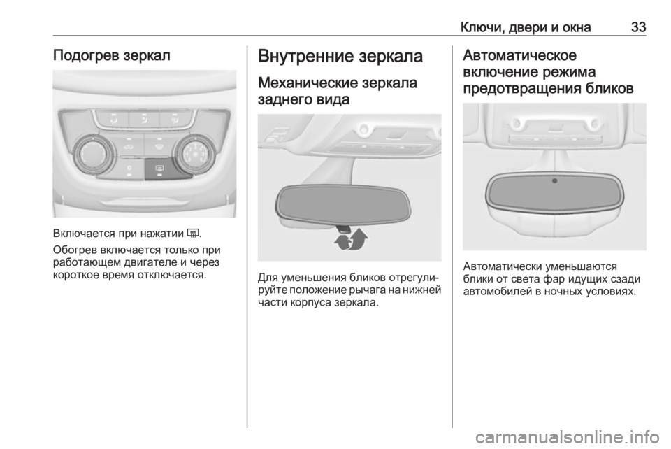
Page 36 of 397
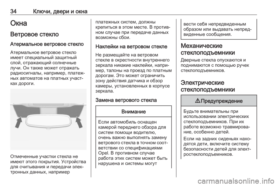
Page 37 of 397
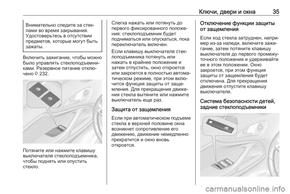
Page 38 of 397
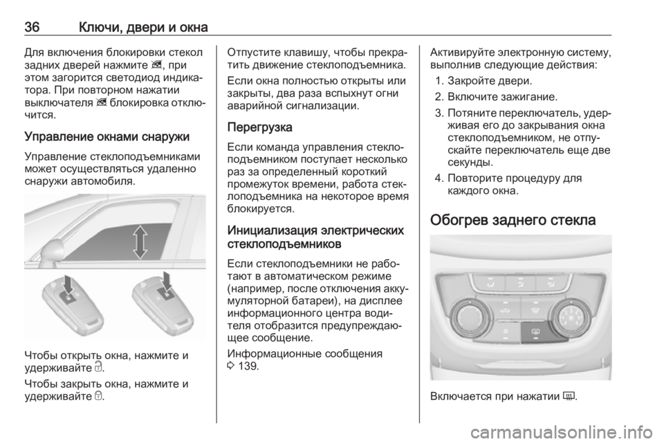
Page 39 of 397
Page 40 of 397
- Load next 10 pages
Trending: давление в шинах, Расход топлива, Освещение, AdBlue, Регулировки, безопасность, Масло
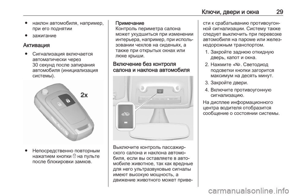
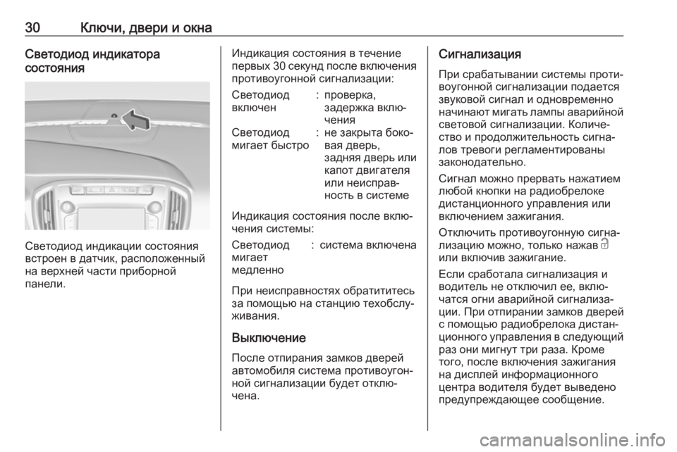
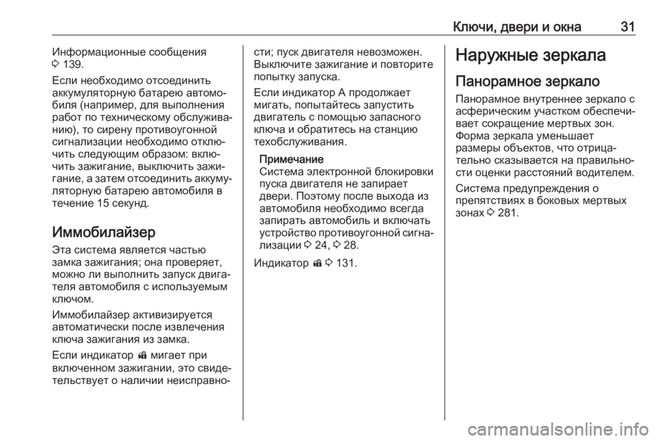
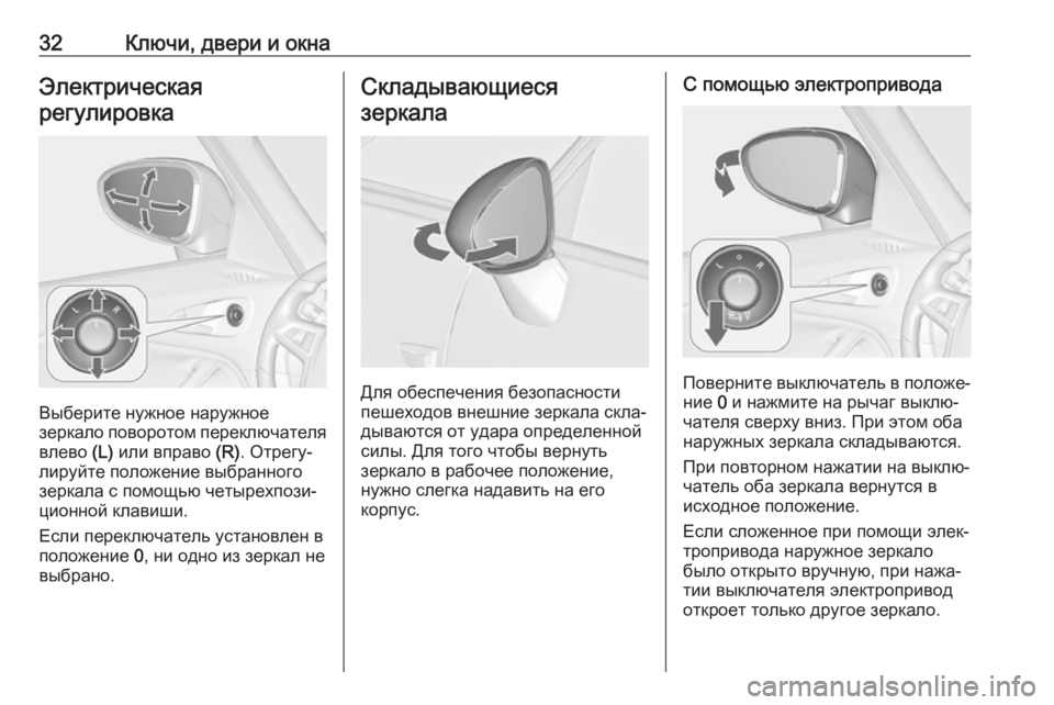
View, print and download for free: OPEL ZAFIRA C 2018 Инструкция по эксплуатации (in Russian), 397 Pages, PDF Size: 10.13 MB. Search in OPEL ZAFIRA C 2018 Инструкция по эксплуатации (in Russian) online. CarManualsOnline.info is the largest online database of car user manuals. OPEL ZAFIRA C 2018 Инструкция по эксплуатации (in Russian) PDF Download. Ключи, двери и окна29● наклон автомобиля, например,при его поднятии
● зажигание
Активац
All product names, logos, and brands are property of their respective owners.
Privacy Policy | About Us & Contact
Инструкция по эксплуатации OPEL Zafira A (18 мб., RUS)
Скачать
Инструкция по эксплуатации OPEL Zafira A (32 мб., RUS)
Скачать
Интерактивная инструкция по эксплуатации и обслуживанию OPEL Zafira A (265 мб., RUS)
Скачать
Инструкция по эксплуатации OPEL Zafira B (160 мб. RUS)
Скачать
Инструкция по эксплуатации OPEL Zafira B (2.5 мб. RUS)
Скачать
Информационный буклет Opel Zafira B (11 мб., RUS)
Скачать
Технические данные для OPEL Zafira B (на русском языке)
Скачать
Технические данные для OPEL Zafira Tourer (на русском языке)
Скачать
Инструкция по эксплуатации OPEL Zafira Tourer (10 мб. RUS)
Скачать
Каталог фирменных аксессуаров для OPEL Zafira Tourer (4 мб. ENG)
Скачать
Информационный буклет Opel Zafira Tourer (15 мб., RUS)
Скачать
РАЗНОЕ
Расшифровка кодов диагностики OBD-2 (на русском языке)
Скачать
TIS 2004 (только схемы, RUS, 282 мб. )
Скачать
EPC 2008 (полная русская версия)
Часть 1 (512 мб.) Скачать
Часть 2 (512 мб.)Скачать
Часть 3 (512 мб.)Скачать
Часть 4 (512 мб.)Скачать
Часть 5 (512 мб.)Скачать
Часть 6 (429 мб.)Скачать
AutoData 2004 (ENG)
Скачать
OPEL TIS 2009 v.106 RUS
Часть 1 (700 мб.) Скачать
Часть 2 (700 мб.)Скачать
Часть 3 (700 мб.)Скачать
Часть 4 (700 мб.)Скачать
Часть 5 (464 мб.)Скачать
Скачать инструкцию по эксплуатации автомагнитолы CD 30 MP3
Скачать
Скачать инструкцию по эксплуатации автомагнитолы VDO 2005
Скачать
Прошивка для штатных систем навигации CD70 и DVD90 автомобилей OPEL (русский голос)
Скачать
Калькулятор ключей для магнитолы CCR-600
Скачать
Скачать инструкцию по эксплуатации автомагнитолы CD 500 (DVD800)
Скачать
Инструкция по эксплуатации штатной навигационной системы Navi 600 (RUS)
Скачать
Инструкция по эксплуатации для штатной магнитолы CD 400 (RUS)
Скачать
Исправление для систем Navi 600/900 (лечение самостоятельных перезагрузок) (RUS)
Скачать
Точки расположения камер для Navi 600 и Navi 900 (вся Россия)
Скачать
Диагностическая программа для адаптера OP-COM (полностью на русском)
Скачать
Диагностическая программа и драйвера для адаптера OP-COM (английский язык, самоустановочный архив)
Скачать
Инструкция и примеры программирования для OP-COM (rus)
Скачать
Справочник автомобилиста (подборка юридических документов и нормативных актов)
Скачать
——————————————————————————————————————
Архиватор для работы с архивами RAR и ZIP
Скачать
Программа Adobe Reader для работы с файлами формата PDF
Скачать
Программа для работы с файлами формата djvu
Скачать
==============================================================
Всем спасибо что со мной)
Ну и не забываем про лайки. Вам не долго, а мне приятно))
Удачи всем!
Подписывайтесь и увидите еще много интересного!))

- Manuals
- Brands
- Opel Manuals
- Automobile
- ZAFIRA 2017
- Owner’s manual
-
Contents
-
Table of Contents
-
Bookmarks
Quick Links
Chapters
-
Table of Contents
3 -
Windows
22 -
36 Seats, Restraints Seats, Restraints Head Restraints
38 -
66 Storage Storage Storage Compartments
68 -
96 Instruments and Controls Instruments and
98 -
130 Lighting Lighting Exterior Lighting
132 -
140 Introduction
142 -
190 Climate Control Climate Control Climate Control Systems
192 -
198 Driving and
200 -
Vehicle Care
261 -
Information
325
Related Manuals for Opel ZAFIRA 2017
Summary of Contents for Opel ZAFIRA 2017
-
Page 1
Owner’s Manual… -
Page 3: Table Of Contents
Contents Introduction ……..2 In brief ……….6 Keys, doors and windows …. 20 Seats, restraints ……36 Storage ……..66 Instruments and controls ….. 96 Lighting ……..130 Infotainment system ….140 Climate control ……190 Driving and operating ….198 Vehicle care …….
-
Page 4: Introduction
Introduction Introduction…
-
Page 5
Operation is prices. Experienced mechanics Introduction similar for right-hand drive trained by Opel work according to vehicles. Your vehicle is a designed specific Opel instructions. ● The Owner’s Manual uses the combination of advanced technology, The customer literature pack should engine identifier code. -
Page 6
We wish you many hours of Disregarding this information may pleasurable driving. endanger life. Adam Opel GmbH 9 Warning Text marked 9 Warning provides information on risk of accident or injury. Disregarding this information may lead to injury. -
Page 7
Introduction… -
Page 8: In Brief
In brief In brief Vehicle unlocking Seat adjustment Longitudinal adjustment Initial drive information Press c to unlock the doors and load compartment. Open the doors by Pull handle, slide seat, release pulling the handles. To open the handle. Try to move the seat back and tailgate, push the touchpad switch forth to ensure that the seat is locked below the handle.
-
Page 9
In brief Backrest inclination Seat height Seat inclination Pull lever, adjust inclination and Lever pumping motion Lever pumping motion release lever. Allow the seat to : seat higher : front end higher engage audibly. down : seat lower down : front end lower Seat position 3 38, Manual seat Seat position 3 38, Manual seat Seat position 3 38, Manual seat… -
Page 10: Head Restraint Adjustment
In brief Head restraint adjustment Seat belt Mirror adjustment Interior mirror Press release button, adjust height, Pull out the seat belt and fasten in belt engage. buckle. The seat belt must not be To adjust the mirror, move the mirror twisted and must fit close against the Head restraints 3 36.
-
Page 11: Steering Wheel Adjustment
In brief Exterior mirrors Steering wheel adjustment Unlock the lever, adjust the steering Select the relevant exterior mirror by wheel, then engage the lever and turning the control to the left (L) or ensure it is fully locked. right (R). Adjust respective mirror by Do not adjust the steering wheel tilting the four-way control.
-
Page 12
In brief Instrument panel overview… -
Page 13
In brief Power windows ….. 31 10 Central locking system ..22 20 Manual parking brake ..214 Exterior mirrors ….. 29 21 Parking assist systems ..235 Hazard warning flashers ..135 Cruise control ….. 220 Eco button for stop-start Sport mode …… -
Page 14
In brief… -
Page 15
In brief Exterior lighting Headlight flash, high beam and Turn and lane-change signals low beam lever up : right turn signal AUTO : automatic light control lever down : left turn signal headlight flash : pull lever switches automatically high beam : push lever between daytime running Turn and lane-change signals… -
Page 16: Washer And Wiper Systems
In brief Hazard warning flashers Horn Washer and wiper systems Windscreen wiper Operated by pressing ¨. Press j. Hazard warning flashers 3 135. : fast : slow INT : interval wiping or automatic wiping with rain sensor OFF : off For a single wipe when the windscreen wiper is off, press the lever down to position 1x.
-
Page 17
In brief Windscreen washer Rear window wiper Rear window washer Pull lever. Push lever. Press the rocker switch to activate the rear window wiper: Windscreen washer system 3 98, Washer fluid is sprayed on the rear window and the wiper wipes a few Washer fluid 3 265. -
Page 18: Climate Control
In brief Climate control Demisting and defrosting the Transmission windows Heated rear window, heated Manual transmission exterior mirrors Press V. Reverse: with the vehicle stationary, Set the temperature control to the depress clutch pedal, press the The heating is operated by pressing highest level.
-
Page 19: Starting Off
In brief Automatic transmission Starting off Starting the engine Check before starting off ● Tyre pressure and condition 3 283, 3 320. ● Engine oil level and fluid levels 3 262. ● All windows, mirrors, exterior lighting and number plates are free from dirt, snow and ice and are operational.
-
Page 20
In brief ● Diesel engines: turn the key to Stop-start system Stop-start system 3 202. position 2 for preheating and wait until control indicator ! extinguishes. ● Turn key to position 3 and release. Starting the engine 3 200. If the vehicle is at a low speed or at a standstill and certain conditions are fulfilled, activate an Autostop as follows:… -
Page 21
In brief Parking lever to position P before Caution removing the ignition key. On 9 Warning an uphill slope, turn the front After running at high engine wheels away from the kerb. speeds or with high engine loads, ● Do not park the vehicle on an operate the engine briefly at a low If the vehicle is on a downhill easily ignitable surface. -
Page 22: Keys, Doors And Windows
Keys, doors and windows Keys, doors and Keys, locks Windows ……..31 Windscreen ……. 31 windows Keys Manual windows ……31 Power windows ……31 Heated rear window ….33 Caution Sun visors ……..33 Keys, locks ……..20 Roller blinds ……. 34 Do not attach heavy or bulky items Keys ……….
-
Page 23: Car Pass
Keys, doors and windows Key with foldaway key section Radio remote control Fault If the central locking system cannot be operated with the radio remote control, it may be due to the following: ● The range is exceeded. ● The battery voltage is too low. ●…
-
Page 24: Memorised Settings
Keys, doors and windows Extend the key and open the unit. be set for each remote control unit Replace the battery (battery type which is used. The status change is CR 2032), paying attention to the available only after locking and installation position.
-
Page 25
Keys, doors and windows Unlocking The setting can be saved for the key Unlocking and opening the being used. Memorised settings tailgate 3 22. Locking Close doors, load compartment and fuel filler flap. Press c. Press c when the ignition is off. The Two settings are selectable: tailgate is released to be unlocked ●… -
Page 26: Automatic Locking
Keys, doors and windows Fault in radio remote control Fault in central locking system system Unlocking Unlocking Manually unlock the driver’s door by turning the key in the lock. The other doors can be opened by pulling the interior handle twice. The load compartment and fuel filler flap cannot be opened.
-
Page 27: Child Locks
Keys, doors and windows Doors The settings can be saved for the key Closing being used 3 22. Load compartment Child locks Tailgate Opening Use the interior handle. Do not push the touchpad switch under the tailgate moulding whilst closing as this will unlock the tailgate 9 Warning again.
-
Page 28: Vehicle Security
Keys, doors and windows Vehicle security General hints for operating Activating tailgate Anti-theft locking system 9 Danger 9 Warning Do not drive with the tailgate open or ajar, e.g. when transporting Do not use the system if there are bulky objects, since toxic exhaust people in the vehicle! The doors gases, which cannot be seen or cannot be unlocked from the…
-
Page 29
Keys, doors and windows ● vehicle inclination, e.g. if it is Note movements triggering the alarm. Also raised Changes to the vehicle interior such switch off when the vehicle is on a as the use of seat covers, and open ferry or train. -
Page 30: Immobiliser
Keys, doors and windows Status LED is integrated into the The alarm can be silenced by Immobiliser sensor on top of the instrument panel. pressing any button on the radio The system is part of the ignition remote control or by switching on the Status during the first 30 seconds of switch and checks whether the ignition.
-
Page 31: Exterior Mirrors
Keys, doors and windows Exterior mirrors Select the relevant exterior mirror by Electric folding turning the control to left (L) or right (R). Adjust respective mirror by tilting Convex shape the four-way control. The convex exterior mirror contains In position 0 no mirror is selected. an aspherical area and reduces blind spots.
-
Page 32: Heated Mirrors
Keys, doors and windows Interior mirrors Heated mirrors Automatic anti-dazzle Manual anti-dazzle Operated by pressing Ü. Dazzle from following vehicles at night is automatically reduced. Heating works with the engine To reduce dazzle, adjust the lever on running and is switched off the underside of the mirror housing.
-
Page 33: Windows
Switch on ignition to operate power important that any windscreen windows. Retained power off 3 200. replacement is performed accurately according to Opel specifications. Otherwise, these systems may not work properly and there is a risk of unexpected behaviour and/or messages from The marked areas on the windscreen these systems.
-
Page 34
Keys, doors and windows Safety function Child safety system for rear windows If the window glass encounters resistance above the middle of the window during automatic closing, it is immediately stopped and opened again. Override safety function In the event of closing difficulties due to frost or the like, switch on the ignition, then pull the switch to the first detent and hold. -
Page 35: Heated Rear Window
Keys, doors and windows Initialising the power windows Heated rear window If the windows cannot be closed automatically (e.g. after disconnecting the vehicle battery), a warning message is displayed in the Driver Information Centre. Vehicle messages 3 122. Activate the window electronics as follows: 1.
-
Page 36: Roller Blinds
Keys, doors and windows Roof The cover of the mirrors should be closed when driving. Glass panel A ticket holder is located on the backside of the sun visor. Panorama roof Roller blinds G : open H : close Press G or H gently to the first detent: the sunblind is opened or closed as long as the switch is operated.
-
Page 37
Keys, doors and windows Safety function 4. Press G (open) gently to the first detent until the sunblind is If the sunblind encounters resistance completely opened. during automatic closing, it is 5. Press H (close) gently to the first immediately stopped and opened detent until the sunblind is again. -
Page 38: Seats, Restraints
Seats, restraints Seats, restraints Head restraints Adjustment Head restraints on front seats Position Head restraints ……36 9 Warning Active head restraints ….37 Front seats ……..38 Only drive with the head restraint Seat position ……38 set to the proper position. Manual seat adjustment ….
-
Page 39: Active Head Restraints
Seats, restraints Horizontal adjustment Head restraints on rear seats forwards. Thus the head is supported so that the risk of whiplash injury is reduced. Note Approved accessories may only be attached if the seat is not in use. To adjust horizontally, pull the head Height adjustment restraint forwards.
-
Page 40: Front Seats
Seats, restraints Front seats ● Sit with shoulders as far back against the backrest as possible. Set the backrest rake so that it is Seat position possible to easily reach the steering wheel with arms slightly 9 Warning bent. Maintain contact between shoulders and the backrest when Only drive with the seat correctly turning the steering wheel.
-
Page 41: Manual Seat Adjustment
Seats, restraints Manual seat adjustment Backrest inclination Seat height Drive only with engaged seats and backrests. Longitudinal adjustment Pull lever, adjust inclination and Lever pumping motion release lever. Allow the backrest to : seat higher engage audibly. down : seat lower Pull handle, slide seat, release handle.
-
Page 42
Seats, restraints Seat inclination Lumbar support Adjustable thigh support Lever pumping motion Adjust lumbar support using the four- Pull the lever and slide the thigh way switch to suit personal support. : front end higher requirements. down : front end lower Moving support up and down: push switch up or down. -
Page 43: Power Seat Adjustment
Seats, restraints Power seat adjustment Seat height Move front of switch upwards/ downwards. 9 Warning Backrest inclination Care must be taken when operating the power seats. There is a risk of injury, particularly for children. Objects could become trapped. Keep a close watch on the seats when adjusting them.
-
Page 44: Armrest
Seats, restraints Lumbar support Adjustable thigh support Armrest Base armrest Adjust lumbar support using the four- Pull the lever and slide the thigh way switch to suit personal support. requirements. The armrest can be slid forwards. Overload Moving support up and down: push If the seat setting is electrically switch up or down.
-
Page 45: Heating
Seats, restraints FlexConsole armrest Pull the handle in front of the armrest and slide armrest rearwards out of the console. Installation in reverse order. Heating Press fastenings inward and fold down locking mechanism at the rear The armrest can be moved in a centre end of the armrest.
-
Page 46: Rear Seats
Seats, restraints Rear seats Seat heating is operational when engine is running and during an Autostop. Second row seats Stop-start system 3 202. 9 Warning When seats or backrests of second and third seat row are being adjusted or folded, keep hands and feet away from the moving area.
-
Page 47
Seats, restraints Pull release lever, fold backrest and Normal seats, all three seats are move the seat to the front. usable and individually adjustable. Lounge seats, only outer seats are usable but with most comfortable adjustment. Seat positioning Pull the loop, adjust inclination, release strap and allow backrest to engage. -
Page 48
Seats, restraints parts, to be used as an armrest. Engage backrest parts in armrest position. ● Pull the handle under each outer seat and slide seats backwards. In the rear area the seats move in transverse direction. Allow seat to engage. This is the most comfortable seating position for the outer seats. -
Page 49
Seats, restraints Seat backrests 9 Warning The backrest inclination can be individually adjusted to three Move seats only to lounge position positions. if seats in the third row are not occupied. Change from lounge seat position to normal seat position ●… -
Page 50: Third Row Seats
Seats, restraints Easy entry function Folding back easy entry First move seat to desired position To permit an easy entrance to the and then raise backrest. seats of the third row, the outer seats of the second row can be tilted. 9 Warning Pull release lever, fold backrest and move the seat towards the front.
-
Page 51
Seats, restraints Setting up the seats ● Fold in interior protection mat 3 83 and remove load compartment cover 3 81. ● Pull up the seat by the upper ● Pull the lower loop, loop, fold out and allow seat to simultaneously swing the engage in upright position. -
Page 52: Seat Belts
Seats, restraints Seat belts Seat belts are designed to be used by Belt pretensioners only one person at a time. Child In the event of a head-on or rear-end restraint system 3 60. collision of a certain severity, the front Periodically check all parts of the belt seat belts are tightened.
-
Page 53: Three-Point Seat Belt
Seats, restraints Three-point seat belt Height adjustment Fasten Loose or bulky clothing prevents the belt from fitting snugly. Do not place 1. Pull belt out slightly. objects such as handbags or mobile 2. Shift the height adjuster upwards phones between the belt and your Withdraw the belt from the retractor, or press button to disengage and body.
-
Page 54
Seats, restraints Unfasten Adjust the height so that the belt lies Remove lower latch plate from across the shoulder. It must not lie retainer and click it into left-hand To release belt, press red button on across the throat or upper arm. buckle (1) at the centre seat. -
Page 55
Seats, restraints Insert in the seat belt holder in the roof height up to max. 150 cm are allowed with the lower latch plate pointing to use the left seat of the third seat forward. row. There is a warning label on the rear Seat belts on the third seat row side of the centre belt, when it is pulled out, to inform the passenger on… -
Page 56: Airbag System
Seats, restraints Airbag system Control indicator v for airbag systems airbag sensing and diagnostic 3 111. module, steering wheel, instrument panel, inner door seals The airbag system consists of a Child restraint systems on front including the speakers, any of the number of individual systems passenger seat with airbag airbag modules, ceiling or pillar…
-
Page 57
Seats, restraints geschützt ist, da dies den TOD oder NL: Gebruik NOOIT een achterwaarts PT: NUNCA use um sistema de SCHWERE VERLETZUNGEN DES gericht kinderzitje op een stoel met retenção para crianças voltado para KINDES zur Folge haben kann. een ACTIEVE AIRBAG ervoor, om trás num banco protegido com um DODELIJK of ERNSTIG LETSEL van AIRBAG ACTIVO na frente do… -
Page 58
Seats, restraints TR: Arkaya bakan bir çocuk emniyet AKTIVNO ČELNO ZRAČNO acest lucru poate duce la DECESUL sistemini KESİNLİKLE önünde bir BLAZINO, saj pri tem obstaja sau VĂTĂMAREA GRAVĂ a AKTİF HAVA YASTIĞI ile nevarnost RESNIH ali SMRTNIH COPILULUI. korunmakta olan bir koltukta POŠKODB za OTROKA. -
Page 59: Front Airbag System
Seats, restraints ET: ÄRGE kasutage tahapoole The airbag label is located on both The inflated airbags cushion the suunatud lapseturvaistet istmel, mille sides of the front passenger sun visor. impact, thereby reducing the risk of ees on AKTIIVSE TURVAPADJAGA injury to the upper body and head of Airbag deactivation 3 59.
-
Page 60: Side Airbag System
Seats, restraints Side airbag system Curtain airbag system The curtain airbag system consists of an airbag in the roof frame on each side. This can be identified by the word AIRBAG on the roof pillars. The curtain airbag system is triggered in the event of a side-on impact of a certain severity.
-
Page 61: Airbag Deactivation
Seats, restraints Use the ignition key to choose the 9 Warning position: OFF* : front passenger airbag is Keep the area in which the airbag deactivated and will not inflates clear of obstructions. inflate in the event of a The hooks on the handles in the collision.
-
Page 62: Child Restraints
Seats, restraints Child restraints Control indicator for airbag deactivation 3 112. Child restraint systems 9 Danger If using a rear-facing child restraint system on the front passenger seat, the airbag system for the front passenger seat must be deactivated. This also applies to certain forward-facing child restraint systems as indicated in If the control indicator ONV…
-
Page 63
Seats, restraints When a child restraint system is being ISOFIX brackets used, pay attention to the following usage and installation instructions and also those supplied with the child restraint system. Always comply with local or national regulations. In some countries, the use of child restraint systems is forbidden on certain seats. -
Page 64
Seats, restraints ISOFIX child restraint systems of Ensure that the child restraint system universal category positions are to be installed is compatible with the marked in the table by IUF 3 63. vehicle type. Ensure that the mounting location of Selecting the right system the child restraint system within the vehicle is correct, see following… -
Page 65: Child Restraint Installation Locations
Seats, restraints Child restraint installation locations Permissible options for fastening a child restraint system with a three-point seat belt On front passenger seat On centre seat On outboard seats in in the second On seats in the Weight class activated airbag deactivated airbag the second row third row Group 0: up to 10 kg X…
-
Page 66
Seats, restraints Permissible options for fitting an ISOFIX child restraint system with ISOFIX brackets This table relates to all ISOFIX child restraint systems On front passenger On outboard seats On centre seat in On the seats in Weight class Size class Fixture seat in the second row the second row… -
Page 67
Seats, restraints : suitable for particular ISOFIX restraint systems of the ‘specific-vehicle’, ‘restricted’ or ‘semi-universal’ categories. The ISOFIX restraint system must be approved for the specific vehicle type (refer to the vehicle type list of the child restraint system) IUF : suitable for ISOFIX forward-facing child restraint systems of universal category approved for use in this weight class : no ISOFIX child restraint system approved in this weight class : move seat forwards as far as necessary and adjust seat backrest as far as necessary to a vertical position to ensure that the belt runs forwards from the upper anchorage point… -
Page 68: Storage
Storage Storage Storage compartments To open the glovebox pull the handle. The glovebox features an adapter for the locking wheel nuts. 9 Warning The glovebox should be closed whilst Storage compartments ….66 driving. Glovebox ……..66 Do not store heavy or sharp Cupholders ……..
-
Page 69
Storage Slidable cupholder in Remove cupholder Rear cupholder FlexConsole armrest The cupholder can be moved in guide rails in the FlexConsole armrest or completely removed. Pull the handle in front of cupholder Additional cupholder are located and remove it vertically out of the between the seats in the third row. -
Page 70: Front Storage
Storage Front storage Overhead console Underseat storage Storage box A storage compartment is located Press button to open storage box. next to the steering wheel. The box may be loaded with max. There is a storage box under the 0.2 kg. passenger’s seat.
-
Page 71: Armrest Storage
Storage Underseat drawer Armrest storage Centre console storage Storage in FlexConsole armrest Centre console Press button in the recess and pull out drawer. Maximum load: 3 kg. To The storage container can be used to close, push in and engage. Press button to open storage store small items.
-
Page 72: Rear Carrier System
Storage Rear console Rear carrier system allows the attachment of electrically- powered bicycles to the rear carrier Rear carrier system for four system. The maximum load per bicycle on the adapter is 20 kg. bicycles The wheelbase of a bicycle must not exceed 1.15 metres.
-
Page 73
Storage Completely pull out the rear carrier Caution system until you hear it engage. Ensure that it is not possible to push Consult your bicycle dealer before in the rear carrier system without attaching bicycles with carbon pulling the release lever again. frames. -
Page 74
Storage Unfold number plate holder Fold out both tail lamps. Fold out wheel recesses Lock the rear carrier system Fold out both wheel recesses. Lift the number plate holder and fold it backwards. Swivel both clamping levers sideways Assembling the bicycle rack as far as they will go. -
Page 75
Storage Lift the rack at the rear (1) and pull it Attaching the first bicycle backwards. Fold up the rack (2). 2. Attach the short mounting bracket to the bicycle frame. Turn the 1. Rotate the pedals into position as knob clockwise to fasten. -
Page 76
Storage 3. Secure both bicycle wheels to the 1. Attach the adapter to the rear wheel recesses using the strap carrier system as shown in the retainers. illustration. 4. Check the bicycle to make sure it is secure. Caution Ensure gap between bicycle and vehicle is at least 5 cm. -
Page 77
Storage Use the longer accessory mounting bracket to attach the third bicycle to the rack. 3. Position the bicycles on the rear 6. Additionally secure both bicycle carrier system alternately aligned wheels of the fourth bicycle to the to the left and to the right. wheel recesses using the Use the short accessory mounting tensioning straps. -
Page 78
Storage ● Without attached adapter: Removing bicycles Undo strap retainers on bicycle tyres. Turn knob anti-clockwise and remove mounting brackets. Detaching adapter Detach the adapter before removing the last bicycle remaining on the rear carrier system. 1. Fold in wheel recesses. Hold frame (1) of rearmost bicycle with one hand and pull the Push the lever (1) to disengage… -
Page 79
Storage Disassembling the bicycle rack 3. Turn the lever (1) forwards and Fold the rack backwards, then push hold. forwards until it stops (1). Arrange mounting brackets as shown 4. Lift the adapter (2) at the rear and Press the rack down at the rear (2). in the illustration. -
Page 80
Storage Fold in tail lamps Push the release lever up and hold. Lift the rear carrier system slightly and Swivel in both tail lamps. push it into the bumper until it Fold in number plate holder engages. Lift the number plate holder and fold Release lever must return to original it forwards. -
Page 81: Load Compartment
Storage Load compartment Caution The seats in the third row can be Before setting up or folding down folded down separately into the seats, all components must be vehicle floor. The seat backrests of removed from the side rails and the second row can be folded forward from the lashing eyes.
-
Page 82
Storage ● Pull the lower loop and 9 Warning simultaneously swing the backrest forwards until the seat is Use vertical position of the lowered into the vehicle floor. backrest only for increased ● Install interior floor mat 3 83 luggage volume and not as a and load compartment cover seating position. -
Page 83: Rear Storage
Storage Floor storage 9 Warning Only drive the vehicle if the backrests are securely locked into position. Otherwise there is a risk of personal injury or damage to the load or vehicle in the event of heavy braking or a collision. Rear storage On both sides of the load compartment there are storage…
-
Page 84
Storage Closing Opening Removing Pull the load compartment cover Remove load compartment cover Open the load compartment cover. towards the rear using the handle and from side brackets. Hold the handle Pull the release lever up and hold. Lift engage it in the retainers at the sides. and guide the load compartment load compartment cover on right side cover until it is fully rolled up. -
Page 85: Rear Floor Storage Cover
Storage Place the housing so that the upper Rear floor storage cover side is facing to the front and the part with the handle points upwards. Floor cover Fasten the load compartment cover in the storage with the Velcro tape. Installing Insert the load compartment cover On versions without third seat row,…
-
Page 86
Storage By folding and expanding the mat there are a range of individual applications possible. The interior protection mat is available in two versions: ● Standard protection mat covers the area between tailgate and second seat row, when third row is complete or if one seat is folded down. -
Page 87
Storage ● Expand the parts of the folded Covering the load compartment up to the backrests of the front seats mat, so that first part is raised up at second row backrest. Only possible with Flex cover interior protection mat being folded at the ●… -
Page 88
Storage ● Open the zipper behind the ● Expand the upper part of double ● Open the zipper from both sides raised up backrest. layer mat over the folded behind the left and right backrest. backrests. ● Pull out the mat until the first part ●… -
Page 89
Storage ● Then expand the small upper Example for covering folded backrest Example for long small objects, e.g. part of double layer mat over the on second row and one folded seat on skis. centre backrest. third row. ● Fold the overlaying rear part under the mat before closing the tailgate. -
Page 90: Load Rails And Hooks
Storage Load rails and hooks Lashing eyes The components are fitted in rails on both side panels using adapters and hooks. Installation of adapters in the rails Install the hooks in the desired The lashing eyes are designed to position in the rails: insert the hook in secure items against slippage, e.g.
-
Page 91
Storage Variable partition net Net pocket Installation of hooks in the rails Insert adapters into the required Insert the hook in the desired position Insert adapters into the required position in the rails. Stick together the first in the upper groove of the rail and position in the rails. -
Page 92: Safety Net
Storage Partitioning net in front of tailgate Safety net The safety net can be installed behind the seats of the second row or the front seats. Passengers must not be transported behind the safety net. Installation behind second row seats ●…
-
Page 93
Storage Installation behind front seats Removal ● Attach hooks of safety net straps to the lashing eyes on both sides ● There are installation openings Push button on the tightener to in the floor in front of the seats. on both sides in the roof frame release the strap on both sides. -
Page 94: Folding Tray
Storage Warning triangle Use the straps to fix. Insert the safety net in the storage and close cover. Stow the warning triangle in the storage of the load compartment floor Folding tray in front of the tailgate. Located in the front seat backrests. First aid kit Open by pulling upwards until it engages.
-
Page 95: Roof Rack System
Storage Roof rack system On another version, first aid kit is Fasten the roof rack in the area of the located in a storage box under the holes, indicated by the arrows in the driver’s seat. Slide the rollo to open or illustration.
-
Page 96: Loading Information
Storage Loading information ● Do not allow the load to protrude To calculate the payload, enter above the upper edge of the the data for your vehicle in the backrests. weights table at the front of this manual. ● Do not place any objects on the load compartment cover or the The EC kerb weight includes instrument panel.
-
Page 97
Storage the combined weight of the roof rack and the load. -
Page 98: Instruments And Controls
Instruments and controls Instruments and Control indicators ….108 High beam assist ….. 116 Turn signal ……. 110 LED headlights ……116 controls Seat belt reminder ….111 Fog light ……..116 Airbag and belt tensioners ..111 Rear fog light ……116 Airbag deactivation ….
-
Page 99: Controls
Instruments and controls Controls Steering wheel controls Heated steering wheel Steering wheel adjustment The Infotainment system, some driver Activate heating by pressing *. assistance systems and a connected Activation is indicated by the LED in mobile phone can be operated via the the button.
-
Page 100: Horn
Instruments and controls The recommended grip areas of the Windscreen wiper/washer Adjustable wiper interval steering wheel are heated quicker and to a higher temperature than the Windscreen wiper other areas. Heating is operational when the engine is running and during an Autostop.
-
Page 101: Rear Window Wiper/Washer
Instruments and controls Adjustable sensitivity of the rain Pull lever. Washer fluid is sprayed sensor onto the windscreen and the wiper wipes a few times. Washer fluid 3 265 Rear window wiper/washer Keep the sensor free from dust, dirt and ice. Wiper lever in position INT.
-
Page 102: Outside Temperature
Instruments and controls Outside temperature If outside temperature drops to 3 °C, a warning message is displayed in the Driver Information Centre. 9 Warning The road surface may already be icy even though the display indicates a few degrees above 0 °C.
-
Page 103: Power Outlets
Instruments and controls For time and date to be set manually, select Off — Manual. If Auto Set is set to Off — Manual, the submenu items Set Time and Set Date become available. Set time and date To adjust the time and date settings, select Set Time or Set Date.
-
Page 104: Cigarette Lighter
Instruments and controls Do not exceed the maximum power Cigarette lighter consumption of 120 watts. With ignition off, the power outlets are deactivated. Additionally the power outlets are deactivated in the event of low vehicle battery voltage. Electrical accessories that are connected must comply with the electromagnetic compatibility requirements laid down in…
-
Page 105: Warning Lights, Gauges And Indicators
Instruments and controls Warning lights, gauges Odometer and indicators Instrument cluster In some versions, the needles of the instruments briefly rotate to the end position when the ignition is switched Speedometer Trip odometer counts up to 9999 km and then restarts at 0. The total recorded distance is Two trip odometer pages are displayed in km.
-
Page 106: Tachometer
Instruments and controls Tachometer Fuel gauge If the LED changes to red and Y illuminates yellow, refuel the tank soon. If the LED illuminates red and Y flashes yellow, refuel immediately. Never run the fuel tank dry. The arrow indicates the vehicle side where the fuel filler flap is located.
-
Page 107: Fuel Selector
The be checked. We recommend an engine remains in the current Opel Repairer authorised for operating mode. The inhibitor servicing natural gas vehicles. Pressing Y switches between petrol remains active until the ignition is and natural gas operation.
-
Page 108
Instruments and controls Liquid gas operation, LPG 1 off : petrol operation Every six months, run the petrol tank down until control indicator I 1 flashes : checking conditions for fuel transition to illuminates, then refuel. This helps liquid gas operation. maintain fuel quality and system Illuminates if function for petrol operation. -
Page 109: Engine Coolant Temperature Gauge
Instruments and controls Seek the assistance of a workshop in Note up to 3 LEDs : engine operating the event of all other faults. In the event of an accident, switch off temperature not the ignition and lights. yet reached Caution 4 to 6 LEDs : normal operating…
-
Page 110: Control Indicators
Instruments and controls Select Vehicle Information Control indicators Menu ? by pressing MENU on the The control indicators described are turn signal lever. Turn the adjuster not present in all vehicles. The wheel to select Remaining Oil Life . description applies to all instrument Remaining oil life duration is indicated versions.
-
Page 111
Instruments and controls Control indicators in the instrument cluster… -
Page 112: Turn Signal
Instruments and controls Overview Electronic Stability Control off m Cruise control 3 116 / Adaptive 3 114 cruise control 3 117 O Turn signal 3 110 b Electronic Stability Control and C Adaptive cruise control 3 117 X Seat belt reminder 3 111 Traction Control system 3 114 A Vehicle detected ahead 3 117 v Airbag and belt tensioners…
-
Page 113: Seat Belt Reminder
Instruments and controls Seat belt reminder Seat belt status on rear seats Airbag and belt tensioners v illuminates red. Seat belt reminder on front seats When the ignition is switched on, the X for driver’s seat or for front control indicator illuminates for passenger seat illuminates or flashes approx.
-
Page 114: Airbag Deactivation
Instruments and controls Airbag deactivation Illuminates when the engine is Risk of fatal injury for an adult running person with deactivated front passenger airbag. Fault in the emission control system. The permitted emission limits may be Charging system exceeded. Seek the assistance of a workshop immediately.
-
Page 115: Operate Pedal
Instruments and controls On some versions, the message to Illuminates 9 Warning operate the clutch pedal is indicated Electric parking brake is operating in the Driver Information Centre Stop. Do not continue your with degraded performance 3 214. 3 122. journey.
-
Page 116: Gear Shifting
Instruments and controls fault in the ABS. The brake system Following distance Electronic Stability Control remains operational but without ABS and Traction Control system E indicates the following distance regulation. setting of the alert timing sensitivity b illuminates or flashes yellow. Antilock brake system 3 214.
-
Page 117: Preheating
Instruments and controls Preheating AdBlue Illuminates when the ignition is switched on and extinguishes shortly ! illuminates yellow. Y flashes yellow. after the engine starts. Preheating is activated. Only AdBlue level is low. Refill AdBlue Illuminates when the engine is activates when outside temperature soon to avoid prevention of the running…
-
Page 118: Low Fuel
Instruments and controls Bleeding the diesel fuel system LED headlights 9 Warning 3 267. f illuminates or flashes yellow. When the engine is off, Immobiliser Illuminates considerably more force is needed to brake and steer. During an d flashes yellow. Fault in the system.
-
Page 119: Adaptive Cruise Control
Instruments and controls Information displays Illuminates white Vehicle detected ahead A illuminates green. The system is on. Driver Information Centre Illuminates green Illuminates green The Driver Information Centre is located in the instrument cluster. Cruise control is active. Set speed is A vehicle ahead is detected in the indicated in the Driver Information same lane.
-
Page 120
Instruments and controls The following indications appear if Turn the adjuster wheel to select a required: submenu of the main menu or to set a numeric value. ● warning messages 3 122 ● gear shift indication 3 114 ● drive mode indication 3 210 ●… -
Page 121
Instruments and controls ● average fuel economy Average fuel economy On vehicles with bi-fuel engines: Instantaneous consumption is Display of average consumption. The ● average vehicle speed indicated for the currently selected measurement can be reset at any ● instantaneous fuel economy mode, LPG, CNG or petrol. -
Page 122: Vehicle Information
Instruments and controls Fuel range, bi-fuel engine Vehicle information ? Speed warning Possible pages are: ● unit ● speed warning ● remaining engine oil life indication ● tyre pressure ● tyre load ● following distance ● traffic sign assistant Unit Display of the approximate total fuel The speed warning function alerts the Press SET/CLR while page is…
-
Page 123: Info Display
Instruments and controls Remaining oil life Economy information menu@ Economy index Indicates an estimate of the oil’s The current fuel consumption is Possible pages are: useful life. The number in percentage indicated on an economic scale. For ● economy trend means the current remaining oil life economical driving, adapt driving and indicates when to change the…
-
Page 124: Vehicle Messages
Instruments and controls Vehicle messages The vehicle has a 7» R 4.0 IntelliLink display with touch-screen functionality. Messages are indicated mainly in the The Info displays can indicate: Driver Information Centre, in some cases together with a warning and ● time 3 100 signal chime.
-
Page 125: Warning Chimes
Instruments and controls Messages in the Info-Display ● If a warning message appears in 1. Switch off immediately any the Driver Information Centre. electrical consumers which are Some important messages appear not required for a safe ride, e.g. ● If the parking assist detects an additionally in the Info-Display.
-
Page 126: Vehicle Personalisation
Instruments and controls Vehicle personalisation Auto Rear Defog: Automatically activates heated rear window. ● Collision / Detection Systems The vehicle’s behaviour can be personalised by changing the settings Park Assist: Activates or in the Info-Display. deactivates the ultrasonic parking assist. Activation is Some of the personal settings for selectable with or without different drivers can be memorised…
-
Page 127: Telematics Service
Instruments and controls Telematics service automatic switching on of the hazard warning flasher feedback rear window wiper when reverse whilst unlocking. gear is engaged. OnStar Remote Lock Feedback: ● Lighting Changes what kind of feedback OnStar is a personal connectivity and is given when locking the vehicle.
-
Page 128
Instruments and controls Depending on the equipment of the OnStar buttons SOS button vehicle, the following services are Press [ to establish a priority available: emergency connection to a specially trained emergency advisor. ● Emergency services and support in the case of a vehicle Status LED breakdown Green: The system is ready with… -
Page 129
Instruments and controls breakdown, a flat tyre and empty fuel To connect a mobile device with the The following functions are available: tank, press Z to establish a Wi-Fi hotspot: ● Lock or unlock vehicle. connection to an advisor. 1. Press j and then select Wi-Fi ●… -
Page 130
Instruments and controls Stolen vehicle assistance Diagnostic report The advisor can look up any address or point of interest and directly send If the vehicle is stolen, report the theft The vehicle automatically transmits the destination to the built-in to the authorities and request OnStar diagnostic data to OnStar which navigation system. -
Page 131
Instruments and controls Note Find the privacy policy in your In any case, if the vehicle is disposed account. of, sold or otherwise transferred, Software updates immediately inform OnStar about OnStar may remotely carry out the changes and terminate the software updates without further OnStar service on this vehicle. -
Page 132: Lighting
Lighting Lighting Exterior lighting Lighting features ……138 Centre console lighting …. 138 Light switch Entry lighting ……138 Exit lighting ……138 Exterior lighting ……130 Battery discharge protection ..139 Light switch ……130 Automatic light control ….. 131 High beam …….
-
Page 133: Automatic Light Control
Lighting Tail lights When the automatic light control High beam function is switched on and the Tail lights are illuminated together engine is running, the system with low/high beam and sidelights. switches between daytime running lights and headlights automatically Automatic light control depending on the external lighting conditions.
-
Page 134: Headlight Flash
Lighting It switches automatically to low beam The high beam assist is activated by LED headlights 3 134. when: pushing the indicator lever twice with a speed above 40 km/h. Headlight range adjustment ● The camera or a sensor in the windscreen detects the lights of The green control indicator f Manual headlight range…
-
Page 135: Headlights When Driving Abroad
Lighting Dynamic automatic headlight There is a white adjuster element on 1. Key in ignition switch. levelling 3 134. the rear of each headlight housing. 2. Pull turn signal lever and hold Turn adjuster element on each (headlight flash). Headlights when driving headlight housing turn with a 3.
-
Page 136: Led Headlights
Lighting LED headlights Cornering lights High beam assist LED lighting system includes: 3 131 ● LED headlights for low and high Reverse parking function beam To assist driver’s orientation when ● cornering lights parking, both corner lights and ● town light reversing light illuminate when ●…
-
Page 137: Hazard Warning Flashers
Lighting Fault in LED headlight system Turn and lane-change Activate temporary flashing by holding the lever just before the signals When the system detects a failure in resistance point. Turning lights will the LED headlight system, f flash until lever is being released. illuminates and a warning is displayed To activate three flashes, tap the in the Driver Information Centre.
-
Page 138: Rear Fog Light
Lighting Light switch in position AUTO: Parking lights Reversing lights switching on front fog lights will switch The reversing light comes on when headlights on automatically. the ignition is on and reverse gear is selected. Rear fog light Misted light covers The inside of the light housing may mist up briefly in poor, wet and cold weather conditions, in heavy rain or…
-
Page 139: Interior Lighting
Lighting Interior lighting Interior lights Rear courtesy lights During entry and exit of the vehicle, Instrument panel the front and rear courtesy lights illumination control automatically switch on and then off after a delay. Note In the event of an accident with airbag deployment the courtesy lights are turned on automatically.
-
Page 140: Reading Lights
Lighting Lighting features Reading lights The following lights will additionally switch on when the driver’s door is opened: Centre console lighting ● illumination of some switches Spotlight incorporated in the interior ● Driver Information Centre lighting comes on when headlights are switched on.
-
Page 141: Battery Discharge Protection
Lighting Activating The settings can be saved for the key being used 3 22. Battery discharge protection To prevent discharge of the vehicle battery when the ignition is switched off, some interior lights are switched off automatically after some time. 1.
-
Page 142: Infotainment System
Infotainment system Infotainment system Introduction Destination input …… 171 Guidance ……… 176 General information Speech recognition ….180 General information ….180 The Infotainment system provides Introduction …….. 140 Usage ……..180 you with state-of-the-art in-car General information ….140 Phone ……..
-
Page 143: Theft-Deterrent Feature
Infotainment system Optionally, the Infotainment system Important information on Radio reception can be operated using the touch operation and traffic safety Radio reception may be disrupted by screen and buttons on the control static, noise, distortion or loss of panel, the controls on the steering 9 Warning reception due to: wheel, or — if provided by your mobile…
-
Page 144: Control Elements Overview
Infotainment system Control elements overview Control panel…
-
Page 145
Infotainment system Display / Touch screen ..148 or skip to previous track when external devices Home menu ……148 Short press: skip to next active ……..161 station when radio active ..154 Screen buttons for access to: Long press: seek down or skip to next track when AUDIO: audio functions when radio active …. -
Page 146
Infotainment system Steering wheel controls or switch between calls when calls are waiting ..184 Press: reduce volume Long press: activate speech recognition ….180 Press: end/decline call ..184 SRC (Source) …… 145 or deactivate speech Press: select audio source .. 145 recognition …… -
Page 147: Usage
Infotainment system Usage Setting the volume Turn X. The current setting is shown Control elements on the display. The Infotainment system is operated When the Infotainment system is via function buttons, a touch screen switched on, the last selected volume and menus that are shown on the is set, provided that it is lower than the display.
-
Page 148
Infotainment system Select l or m to display the picture or For a detailed description of preparing and establishing a movie menu. Select the desired Bluetooth connection between the picture or movie file to show the Infotainment system and a mobile respective item on the display. -
Page 149
Infotainment system Select Projection to start the projection function. Depending on the smartphone connected, a main menu with different selectable apps is displayed. For a detailed description 3 164. (R 4.0 IntelliLink, if Projection not available) To start the BringGo navigation application, select Nav. -
Page 150: Basic Operation
Infotainment system Basic operation When operating the menus, press 9 Note In subsequent chapters, the in the respective submenu to return to operating steps for selecting and the next higher menu level. The Infotainment system display has activating a screen button or menu When no 9 screen button is a touch-sensitive surface that allows item via the touch screen will be…
-
Page 151
Infotainment system Note To scroll through a list of menu items, Scrolling pages Constant pressure must be applied you may optionally: and the finger must be moved at a ● Place your finger anywhere on constant speed. the screen and move it upwards or downwards. -
Page 152: Tone Settings
Infotainment system Note Note Equaliser mode In subsequent chapters, the The j symbol is only available if Use this setting to optimise the tone operating steps for scrolling pages route guidance is active. for the style of music, e.g. Rock or via the touch screen will be Tone settings Classical.
-
Page 153: Volume Settings
Infotainment system Setting balance and fader Adjusting the speed Use the illustration at the right side of compensated volume the menu to adjust balance and fader. Press ; and then select Settings. To define the point in the passenger Select Radio, scroll through the list compartment where the sound is at its and then select Auto Volume.
-
Page 154: System Settings
Infotainment system System settings Set Date Format To adjust the language for the menu texts: touch the desired language. To select the desired date format, The following settings concern the select Set Date Format and choose whole system. All other settings are Text scroll function between the available options in the described by theme in the respective…
-
Page 155
Infotainment system Black display function In each case, a warning message is A pop-up is displayed. Confirm the displayed. Select Continue to reset pop-up message. If you do not want to see the the settings. illuminated display, e.g. during night Navigation settings time, you can turn the display off. -
Page 156: Radio
Infotainment system Radio For a system update, contact your Station search workshop. Automatic station search Usage Vehicle settings Activating radio Vehicle settings are described in the Owner’s Manual. Press ; and then select Audio. The audio main menu last selected is displayed.
-
Page 157
Infotainment system Note Station lists Category lists FM waveband: when the RDS Select Menu in the radio main menu Numerous radio stations broadcast a function is activated, only RDS to open the corresponding PTY code, which specifies the type of stations 3 157 are searched for, and waveband-specific submenu. -
Page 158: Favourite Lists
Infotainment system Note Favourite lists To store the currently active radio The currently received radio station station to a preset screen button: Stations of all wavebands can be is indicated by the l symbol next to touch and hold the desired screen stored manually in the favourite lists.
-
Page 159: Radio Data System (Rds)
Infotainment system Radio data system (RDS) RDS configuration Note In the station list, TP is displayed RDS is a service of FM stations that Touch Menu in the bottom line of the next to the stations providing a traffic considerably facilitates the finding of FM radio main menu to open the programme.
-
Page 160: Digital Audio Broadcasting
Infotainment system Select Menu in the bottom line of the data and a multitude of other data improved, whereas AM or FM FM radio main menu to open the services including travel and reception is considerably corresponding waveband-specific traffic information. impaired in such cases.
-
Page 161: External Devices
Infotainment system External devices Scroll through the list and select DAB Scroll through the list and activate or Announcements to display a list of the deactivate DAB-FM Linking. categories available. General information L Band Activate all or just the desired A USB port for the connection of announcement categories.
-
Page 162
Infotainment system When connected to the USB port, Connecting a device Caution various functions of the devices For a detailed description on how to mentioned above can be operated via establish a Bluetooth connection Avoid disconnecting the device the controls and menus of the 3 181. -
Page 163: Playing Audio
Infotainment system Audio files The maximum resolution is 1280 x Select Source in the interaction 720 pixels. The frame rate must be selector bar and then select the The playable audio file formats are less than 30 fps. desired audio source to open the MP3 (MPEG-1 Layer 3, MPEG-2 respective audio main menu.
-
Page 164: Displaying Pictures
Infotainment system Touch t within the first two seconds main screen to display the respective Note audio menu and then select Browse For your safety, some features are of the track playing to return to the Music. disabled while driving. previous track.
-
Page 165: Playing Movies
Infotainment system Touch the screen to hide the menu Picture menu Display settings bar. Touch the screen again to Select Display Settings to open a Select Menu in the bottom line of the redisplay the menu bar. submenu for the adjustment of screen to display the Picture Menu.
-
Page 166: Using Smartphone Applications
Infotainment system Returning to the beginning of the Display settings current movie Select Display Settings to open a Touch d after five seconds of the submenu for adjustment of brightness and contrast. movie playing. Touch + and — to adjust the settings. Fast forwarding and rewinding Touch and hold d or c.
-
Page 167
Infotainment system Activating phone projection in the Returning to the Infotainment screen Starting BringGo settings menu Press ;. To start the app, press ; and then Press ; to display the home screen select the Nav icon. BringGo and then select Settings. The main menu of the application is Scroll through the list to shown on the display of the… -
Page 168: Navigation
Infotainment system Navigation Route guidance is provided by voice followed. If a navigation instruction output and an arrow, as well as with contradicts traffic regulations, the the aid of a multi-colour map display. General information traffic regulations always apply. Important information The navigation system will reliably Functioning of the navigation guide you to your destination.
-
Page 169: Usage
All required map data is stored within Route guidance not active the Infotainment system. To update the navigation map data, purchase new data at the Opel Dealer or on our home page http:// opel.navigation.com/. You are provided with a USB device containing the update.
-
Page 170
Infotainment system Map manipulation Cancel screen button During active route guidance, a Scrolling Cancel screen button is displayed on To scroll the map, place your finger the left side of the screen. anywhere on the screen and move it To cancel the active route guidance up, down, left or right depending on session, select Cancel. -
Page 171
Infotainment system When selecting a desired exit, you To save the current location as Depending on the former setting, the can access points of interest in the favourite, select Favourite. The f screen button is labelled 3D Head respective area and start route icon is filled and the location is saved Up, 2D Head Up or 2D North Up. -
Page 172
Infotainment system The default setting is Auto. When POI (Points of Interest) icons on the Select L on the map to display the Auto is activated, the screen adjusts Options menu. Select Navigation automatically. Settings and then Time to Destination POIs are points of general interest, Format. -
Page 173: Destination Input
Infotainment system Voice guidance If Normal voice guidance is activated, Destination input a voice announces the next turning The navigation application provides The route guidance process can be manoeuvre to be taken. different options to set a destination supported by voice prompts given out If Beep only is activated, only beep for route guidance.
-
Page 174
Infotainment system To change the name of the personal address, select c to hide the keyboard and select one of the items in the list. Alternatively, enter a new name in the first entry field. If necessary, tap within one of the entry fields to redisplay the keyboard and select Done. -
Page 175
Infotainment system To access the number and symbol To redisplay the keyboard, tap within keyboard, select ?123. Select ABC at the entry field. the same position on the keyboard to If desired, select a destination from return to the letter keyboard. the list. -
Page 176
Infotainment system Recent destinations The position of a favourite in the list address) you want to search for. All can be changed. Enter the favourites entries containing a word starting with The recent destinations list is list, select n next to the desired these letters are displayed. -
Page 177
Infotainment system entry field (default setting: Nearby) Choose between the tabs: and then use the category search ● Along Route: possible menu. destinations along the route currently active If required, scroll to the desired page and then select one of the main ●… -
Page 178: Guidance
Infotainment system Setting the route Note If you select Go, route guidance to In case the system finds more than the destination first selected is one possible route, you can choose stopped and route guidance to the between the routes suggested. new destination is started.
-
Page 179
Infotainment system Starting and cancelling route In case a phone number is available, select y to start a phone call. guidance To change the order of the To start route guidance, select Go in destinations, select h in the field of the Details menu after a destination the destination whose position is to be has been selected 3 171. -
Page 180
Infotainment system Traffic settings If route guidance is active, choose between the tabs: There are different options available ● Along Route: traffic events along concerning traffic events. the active route Traffic list ● Nearby: traffic events close to the The traffic list contains all traffic current location of the vehicle events detected by the system. -
Page 181
Infotainment system A list of all traffic stations currently If you want to be consulted when a Activate the desired option: available is displayed. route is modified, activate Always ● Fastest for the fastest route ask. By default, Auto is activated. The ●… -
Page 182: Speech Recognition
Infotainment system Speech recognition Phone As soon as a beep is heard, you can say a command. For information on the commands supported, see the General information General information operating instructions for your The voice pass-thru application of the The Phone portal provides you with smartphone.
-
Page 183: Bluetooth Connection
Infotainment system Important information for Select Bluetooth to display the interference is caused by the Bluetooth menu. operation and traffic safety mobile phone or if dangerous situations can occur. 9 Warning Bluetooth Mobile phones have effects on The Phone portal is certified by the your environment.
-
Page 184
Infotainment system connected previously, the Confirm the messages on the Infotainment system establishes Infotainment system and the the connection automatically. Bluetooth device. ● Bluetooth operation considerably ● If SSP (secure simple drains the device’s battery. pairing) is not supported: Therefore, connect the device to On the Infotainment system: the USB port for charging. -
Page 185: Emergency Call
Infotainment system messages displayed on the Disconnecting a device The information displayed includes Bluetooth device. Device Name, Address, and PIN Press ; and then select Settings. Code. If this function is not supported by Select Bluetooth and then Device the Bluetooth device, a Management to display the Emergency call corresponding message is…
-
Page 186: Operation
Infotainment system Operation Phone main menu on all mobile phone networks; it is possible that they cannot be made As soon as a connection via Press ; and then select PHONE to when certain network services Bluetooth has been set up between display the respective menu.
-
Page 187
Infotainment system Initiating a phone call Search menu If the phone book contains a great Entering a phone number number of entries, you can search for Press ; and then select Phone. the desired contact via the search menu. Enter a telephone number using the keypad in the phone main menu. -
Page 188
Infotainment system For example: If the contact you wish to search for starts with ‘g’ select the ghi screen button. All contacts containing one of the letters on this button, in the example ‘g’, ‘h’, and ‘i’, are displayed. 2. Select the button containing the second letter of the contact you wish to search for. -
Page 189
Infotainment system Using speed dial numbers Select one of the ringtones. Speed dial numbers that are stored Functions during a call on the mobile phone can also be dialled using the keypad of the phone During an ongoing phone call, the main menu. -
Page 190: Equipment
Infotainment system To reactivate the microphone, Mobile phones and CB radio ways of using devices with a deactivate n. transmission power exceeding equipment 10 watts. Ending a phone call Installation instructions and Use of a hands-free attachment Select J to end the call. without external antenna with mobile operating guidelines telephone standards GSM…
-
Page 191
Infotainment system Caution Mobile telephones and radio equipment may lead to malfunctions in the vehicle electronics when operated inside the vehicle with no exterior antenna, unless the above mentioned regulations are observed. -
Page 192: Climate Control
Climate control Climate control Climate control systems Heating will not be fully effective until the engine has reached normal operating temperature. Heating and ventilation system Air distribution Climate control systems ….. 190 Heating and ventilation system 190 l : to windscreen and front door Air conditioning system …
-
Page 193: Air Conditioning System
Climate control Air conditioning system Press n again to switch off cooling. compartment air deteriorates, The air conditioning system cools and which may cause the vehicle dehumidifies (dries) as soon as the occupants to feel drowsy. outside temperature is slightly above the freezing point.
-
Page 194: Electronic Climate Control System
Climate control Demisting and defrosting the Note If V is pressed while the engine is windows V running, an Autostop will be inhibited until V is pressed again. If l is pressed with the fan switched on and the engine running, an Autostop will be inhibited until l is pressed again or until the fan is switched off.
-
Page 195
Climate control Automatic mode AUTO ● Press n to switch on optimal cooling and demisting. The LED in the button illuminates to indicate activation. ● Set the preselected temperatures for driver and front passenger using the left and right rotary knobs. Recommended temperature is 22 °C. -
Page 196
Climate control Demisting and defrosting the If V is pressed while the engine is in an Autostop, the engine will restart windows V automatically. ● Press V. The LED in the button If l is pressed with the fan switched illuminates to indicate activation. -
Page 197
Climate control Press the lower button to decrease or Cooling n Activation or deactivation of cooling upper button to increase fan speed. operation after engine start can be Press n to switch on cooling. The fan speed is indicated by the changed in the Settings menu in the Activation is indicated by the LED in number of segments in the display. -
Page 198: Auxiliary Heater
Climate control Air vents directed towards it. If windscreen mists up from outside, activate windscreen wiper and deactivate l. Adjustable air vents At least one air vent must be open while the cooling is on. Direct the flow of air by tilting and swivelling the slats.
-
Page 199: Fixed Air Vents
Climate control Maintenance Air conditioning regular operation Air intake In order to ensure continuously efficient performance, cooling must be operated for a few minutes once a month, irrespective of the weather and time of year. Operation with cooling is not possible when the outside temperature is too low.
-
Page 200: Driving And Operating
Driving and operating Driving and Brakes ……..214 Trailer hitch …….. 254 Antilock brake system ….. 214 General information ….254 operating Parking brake ……214 Driving characteristics and Brake assist ……216 towing tips ……255 Hill start assist ……216 Trailer towing ……
-
Page 201: Driving Hints
Driving and operating Driving hints Starting and operating Use only floor mats which fit properly and are fixed by the retainers on the driver’s side. Control of the vehicle New vehicle running-in Do not brake unnecessarily hard for Steering Never coast with engine not the first few journeys.
-
Page 202: Retained Power Off
Driving and operating Steering wheel lock Starting the engine Remove key from ignition switch and turn steering wheel until it engages. 9 Danger Never remove the key from ignition switch during driving as this will cause steering wheel lock. Retained power off The following electronic systems can 0 : ignition off: Some functions work until the driver’s door is opened…
-
Page 203: Overrun Cut-Off
Driving and operating Turn key briefly to position 3 and Starting the vehicle at low Possible reasons for a non-starting release: an automatic procedure engine: temperatures operates the starter with a short delay ● Clutch pedal not operated The start of the engine without until the engine is running, see (manual transmission).
-
Page 204: Stop-Start System
Driving and operating Stop-start system Deactivation The engine will be switched off while the ignition stays on. The stop-start system helps to save fuel and to reduce the exhaust Indication emissions. When conditions allow, it switches off the engine as soon as the vehicle is at a low speed or at a standstill, e.g.
-
Page 205
Driving and operating ● The stop-start system is not Certain settings of the climate control If the selector lever is shifted out of manually deactivated. system may inhibit an Autostop. See neutral before depressing the clutch Climate control chapter for more pedal first, control indicator — ●… -
Page 206: Parking
Driving and operating ● The vehicle is driven at least at the release button. Apply as ● Close the windows. walking speed. firmly as possible on a downhill ● Remove the ignition key from ● The climate control system slope or uphill slope. Depress the ignition switch.
-
Page 207: Engine Exhaust
Driving and operating Engine exhaust Note Diesel particle filter In the event of an accident with airbag deployment, the engine is Automatic cleaning process turned off automatically if the vehicle 9 Danger The diesel particle filter system filters comes to a standstill within a certain harmful soot particles out of the time.
-
Page 208: Catalytic Converter
Driving and operating indicated by illumination of % and a Caution Caution warning message in the Driver Information Centre. If possible, do not interrupt Fuel grades other than those listed % illuminates along with a warning cleaning process. Drive until on pages 3 246, 3 313 could message when diesel particle filter is cleaning is completed to avoid the…
-
Page 209: Adblue
Driving and operating AdBlue Level warnings Caution Depending on the calculated range of General information Avoid contact of the paintwork with AdBlue, different messages are AdBlue. The selective catalytic reduction displayed in the Driver Information (BlueInjection) is a method to Centre.
-
Page 210
● AdBlue Empty Refill Now at Opel dealers and other retail Consult a workshop for assistance. outlets. ● Engine Will Not Restart. Refilling AdBlue Since AdBlue has a limited… -
Page 211
Driving and operating 1. Continuously drive the vehicle The vehicle must be parked on a level 5. Open AdBlue canister. for 10 minutes making sure that surface. 6. Mount one end of the hose on the vehicle speed is always higher The filler neck for AdBlue is located canister and screw the other end than 20 km/h. -
Page 212: Automatic Transmission
Driving and operating Automatic transmission In manual mode, M and the number < : upshift in manual mode of the selected gear is indicated. ] : downshift in manual mode R indicates reverse gear. The automatic transmission permits automatic gearshifting (automatic N indicates neutral position.
-
Page 213: Manual Mode
Driving and operating The engine can only be started with Parking If a higher gear is selected when the lever in position P or N. When vehicle speed is too low, or a lower Apply the parking brake and engage position N is selected, press the brake gear when vehicle speed is too high, pedal or apply the parking brake…
-
Page 214: Fault
Driving and operating ● The automatic neutral shift Fault function automatically shifts gear In the event of a fault a message is to idling when the vehicle is displayed in the Driver Information stopped with a forward gear Centre. Vehicle messages 3 122. engaged and the brake pedal is The transmission no longer shifts pressed.
-
Page 215: Manual Transmission
Driving and operating Manual transmission 3. Push down the release lever and Caution move the selector lever out of P or N. If these positions are engaged It is not advisable to drive with the again, the selector lever will be hand resting on the selector lever.
-
Page 216: Brakes
Driving and operating Brakes ABS starts to regulate brake pressure Fault as soon as a wheel shows a tendency to lock. The vehicle remains 9 Warning The brake system comprises two steerable, even during hard braking. independent brake circuits. ABS control is made apparent If there is a fault in the ABS, the If a brake circuit fails, the vehicle can through a pulse in the brake pedal…
-
Page 217
Driving and operating Manual parking brake Control indicator R 3 112. 3 113. The electric parking brake operates automatically with Electric parking brake adequate force. Before leaving the vehicle, check the electric parking brake status. Control indicator m 3 113. The electric parking brake can always be activated, even if the ignition is off. -
Page 218: Brake Assist
Driving and operating Vehicles with automatic transmission: Apply electric parking brake: pull and Maintain steady pressure on the Engaging D and then depressing the hold switch m for more than five brake pedal as long as full braking is accelerator pedal releases the required.
-
Page 219: Ride Control Systems
Driving and operating Ride control systems A status message appears in the 9 Warning Driver Information Centre when TC is deactivated. Traction Control system Do not let this special safety feature tempt you into taking risks The Traction Control system (TC) is a when driving.
-
Page 220: Electronic Stability Control
Driving and operating Have the cause of the fault remedied illuminate and status messages 9 Warning by a workshop. appear in the Driver Information Centre. Do not let this special safety Electronic Stability Control feature tempt you into taking risks when driving.
-
Page 221: Interactive Driving System
Driving and operating Fault In each driving mode Flex Ride TOUR mode networks the following electronic If there is a fault in the system the systems: control indicator b illuminates ● Continuous Damping Control continuously and a message appears ● Accelerator Pedal Control in the Driver Information Centre.
-
Page 222: Driver Assistance Systems
Driving and operating Driver assistance changes the settings within the Personalised settings in the Sport selected driving mode or, when mode systems recognising greater variations, the The driver can select the functions of driving mode is changed for the the SPORT mode when SPORT is length of variation.
-
Page 223
Driving and operating For safety reasons, the cruise control Switching on Increase speed cannot be activated until the foot With cruise control active, hold thumb brake has been operated once. wheel turned to RES/+ or briefly turn Activation in first gear is not possible. to RES/+ repeatedly: speed increases continuously or in small increments. -
Page 224: Speed Limiter
Driving and operating Deactivation Resume stored speed The preset speed limit is displayed in the Driver Information Centre when Press y, control indicator m in Turn thumb wheel to RES/+ at a the system is active. speed above 30 km/h. The stored instrument cluster illuminates white.
-
Page 225: Adaptive Cruise Control
Driving and operating Set speed limit In the event of an emergency, it is Resume limit speed possible to exceed the speed limit by Accelerate to the desired speed and Turn thumb wheel to RES/+. The depressing the accelerator pedal briefly turn thumb wheel to SET/-: the stored speed limit will be obtained firmly nearly to the final point.
-
Page 226
Driving and operating Adaptive cruise control automatically For safety reasons, the system Switching on decelerates the vehicle when cannot be activated before the brake approaching a slower moving vehicle. pedal has been depressed once after It then adjusts the vehicle speed to switching on ignition. -
Page 227
Driving and operating large increments, or activate SET/- 9 Warning repeatedly: speed decreases in small increments. Accelerating by the driver If the vehicle is driven with adaptive deactivates automatic braking by cruise control active much slower the system. This is indicated as a than the desired speed, e.g. -
Page 228
Driving and operating 9 Warning The driver accepts full responsibility for the appropriate following distance based on traffic, weather and visibility conditions. Following distance must be adjusted or the system switched off when required by the prevailing conditions. Detecting the vehicle ahead Press E, the current setting is shown The selected following distance is indicated by filled distance bars on… -
Page 229
Driving and operating Deactivation ● Driving on steep inclines. Switching off ● Radar sensor is blocked by an ice Adaptive cruise control is deactivated Press C to switch off adaptive cruise or water film. by the driver when: control. The control indicator m and ●… -
Page 230
Driving and operating visibility. In case of sensor Bends entering a bend and in general to blockage, clean the sensor adapt the speed to the road type and cover. to existing speed limits. System limits ● The system’s automatic brake force does not permit hard braking and the braking level The adaptive cruise control calculates… -
Page 231
Driving and operating the set speed. For this reason, System performance on hills and Radar unit decrease the set speed before the when towing a trailer depends on exit or before the entry. vehicle speed, vehicle load, traffic conditions and the road gradient. It Vehicle path changes may not detect a vehicle in your path while driving on hills. -
Page 232: Forward Collision Alert
Driving and operating Depending on the vehicle’s consult a workshop to verify and equipment, there are two variants of correct the adaptive cruise control the forward collision alert available: sensor position. ● Forward collision alert based on radar system Settings on vehicles equipped with Settings can be changed in the adaptive cruise control 3 223.
-
Page 233
Driving and operating Selecting the alert sensitivity Caution The alert sensitivity can be set to near, medium or far. The colour lighting of this control indicator does not correspond to local traffic laws on following distance. The driver bears full responsibility for maintaining safe following distance according to applicable traffic rules, weather… -
Page 234
Driving and operating Settings Alerting the driver The vehicle ahead control indicator Settings can be changed in the A illuminates green in the instrument vehicle personalisation menu in the cluster when the system has detected Info-Display. a vehicle in the driving path. Select the relevant setting in Settings in the Info-Display. -
Page 235: Following Distance Indication
Driving and operating Driver Information Centre and a depending on the vehicle equipment, The complete attention of the warning chime sounds. Depress the either the radar behind the radiator driver is always required while brake pedal, if it is required by the grille or the front camera in the driving.
-
Page 236: Active Emergency Braking
Driving and operating If there is no vehicle ahead or the the active emergency braking Brake preparation system vehicle ahead is out of range, two applies, the driver is warned by the When approaching a vehicle ahead dashes will be displayed: -.- s. forward collision alert 3 230.
-
Page 237: Parking Assist
Driving and operating film, dust, ice or snow. In case of If the system does not work as it 9 Warning sensor blockage, clean the sensor should, vehicle messages are cover. displayed in the Driver Information Active emergency braking is not Centre.
-
Page 238
Driving and operating for front obstacles sounds via the Depending on which side of the front speakers, for rear obstacles it vehicle is closer to an obstacle, you sounds via the rear speakers. will hear acoustic warning signals on the respective side of the vehicle. The interval between the sounds becomes shorter as the vehicle gets closer to that obstacle. -
Page 239
Driving and operating Rear obstacles are indicated during the ignition cycle or until acoustically and visually at the same activation in personalisation menu time. again. Vehicle personalisation 3 124. Front obstacles are indicated visually When using the trailer hitch change first. -
Page 240: Side Blind Spot Alert
Driving and operating Side blind spot alert external noise sources may cause Parking assist systems do not the system to fail to detect detect objects outside the The side blind spot alert system obstacles. detection range. detects and reports objects on either side of the vehicle, within a specified Special attention must be paid to Note…
-
Page 241
Driving and operating When the system detects a vehicle in Side blind spot alert is active from sides. The height of the zone is the side blind zone while driving speeds of 10 km/h up to 140 km/h. approx. between half a metre and forward, either while passing a Driving faster than 140 km/h two metres off the ground. -
Page 242: Rear View Camera
Driving and operating Rear view camera Functionality Due to the high position of the camera, the rear bumper can be seen The rear view camera assists the on the display as a guide to position. driver when reversing by displaying a The area displayed by the camera is view of the area behind the vehicle.
-
Page 243: Traffic Sign Assistant
Driving and operating Warning symbols Deactivation of guiding lines and The rear view camera may not warning symbols operate properly when: Warning symbols are indicated as triangles 9 on the picture which ● The surrounding area is dark. shows obstacles detected by the rear ●…
-
Page 244
Driving and operating Add-on signs An exclamation mark in a frame ● additional hints to traffic signs indicates that there is an additional sign detected which is not recognised ● restriction of trailer towing by the system. ● tractor constraints The system operates without loss of ●… -
Page 245
Driving and operating Choose ? via MENU and select Once activated and when the traffic sign detection page is currently not traffic sign assistant page with the displayed, newly detected speed limit adjuster wheel on the turn signal lever 3 117. and no passing signs are displayed as popup alerts in the Driver When another page on the Driver… -
Page 246
Driving and operating Alternatively, SET/CLR can be Reasons for signs being cleared: pressed for three seconds to clear the ● A predefined distance was driven content of the page. or time has elapsed (differs for Upon successful reset, a chime will each sign type) sound and the following “Default ●… -
Page 247: Lane Departure Warning
Driving and operating changes and warns the driver in the The lane departure warning system is Caution event of an unintended lane change activated by pressing ). The via visual and acoustic signals. illuminated LED in the button The system is intended to help the indicates that the system is switched Criteria for the detection of an driver within a defined speed…
-
Page 248: Fuel
Driving and operating Fuel Fault Caution The lane departure warning system Fuel for petrol engines may not operate properly when: Use of fuel that does not comply to EN 228 or equivalent can lead to Only use unleaded fuel that complies ●…
-
Page 249: Fuel For Diesel Engines
Driving and operating Some fuel does not contain sufficient Some fuels, mainly high octane Caution quantities of additive to keep fuel racing fuels, can contain an octane injectors and intake valves clean. enhancing additive called Frequent usage of diesel fuel methylcyclopentadienyl manganese To make up for this lack of containing more than 15 ppm…
-
Page 250: Fuel For Natural Gas Operation
Driving and operating properly. Make sure to fill winter Fuel for liquid gas operation Refuelling grade diesel fuel at ambient Liquid gas is known as LPG temperatures below 0°C. (Liquefied Petroleum Gas) or under Arctic grade diesel fuel can be used its French name GPL (Gaz de Pétrole in extreme cold temperatures below Liquéfié).
-
Page 251
Driving and operating 9 Danger Fuel is flammable and explosive. No smoking. No naked flames or sparks. If you can smell fuel in your vehicle, have the cause of this remedied immediately by a workshop. Caution The fuel filler cap can be retained in The fuel filler flap can only be opened In case of misfuelling, do not the bracket on the fuel filler flap. -
Page 252
Driving and operating Vehicles with misfuel inhibitor The misfuel inhibitor ensures that the The funnel is located on the right- flap of the fuel filler neck can only be hand side storage compartment in the 9 Warning opened by using a nozzle for diesel load compartment. -
Page 253
Driving and operating The fuel filler flap can only be opened German Erdgasfahrzeuge if the vehicle is unlocked. Release the English NGVs = Natural Gas Vehi‐ fuel filler flap by pushing the flap. cles 9 Warning French Véhicules au gaz naturel — or — Véhicules GNV Refuel only with a maximum output pressure of 250 bar. -
Page 254
Remove adapter and stow in vehicle. Opel Distributors and from Opel Fit protective cap to prevent the Authorised Repairers. ACME Adapter: Screw the nut of the penetration of foreign bodies into the filling nozzle onto the adapter. -
Page 255: Fuel Consumption — Co 2 — Emissions
Fuel consumption — CO Emissions Petrol and Diesel engines The fuel consumption (combined) of the model Opel Zafira is within a range of 9.2 to 4.5 l/100 km. The CO emission (combined) is within a range of 182 to 119 g/km.
-
Page 256: Trailer Hitch
Driving and operating Trailer hitch General information Natural gas The fuel consumption information The official fuel consumption and was obtained using reference fuel General information specific CO emission figures quoted G20 (methane proportion relate to the EU base model with Only use towing equipment that has 99 — 100 mol%) under prescribed standard equipment.
-
Page 257: Driving Characteristics And Towing Tips
Driving and operating Driving characteristics and Trailer towing The permissible gross train weight must not be exceeded. This weight is towing tips Trailer loads specified on the identification plate Before attaching a trailer, lubricate 3 308. The permissible trailer loads are the coupling ball.
-
Page 258: Towing Equipment
Driving and operating Rear axle load Stowage of coupling ball bar Fitting the coupling ball bar When the trailer is coupled and the towing vehicle fully loaded, the permissible rear axle load (see identification plate or vehicle documents) may be exceeded by 60 kg, the gross vehicle weight rating may be exceeded by 60 kg.
-
Page 259
Driving and operating Checking the tensioning of the Insert the tensioned coupling ball bar coupling ball bar in the opening and push firmly upwards until it audibly engages. The rotary handle snaps back into its original position, resting against the coupling ball bar without a gap. -
Page 260: Trailer Stability Assist
Driving and operating Attach breakaway stopping cable to Dismounting the coupling ball bar selectively braked until the snaking eye. ceases. While system is working keep steering wheel as still as possible. Check that the coupling ball bar is Trailer stability assist (TSA) is a correctly installed function of the Electronic Stability ●…
-
Page 261: Vehicle Care
Vehicle care Vehicle care Interior lights ……275 Appearance care ……. 300 Instrument panel illumination … 275 Exterior care ……300 Electrical system ……275 Interior care ……302 Fuses ……..275 General Information ….260 Engine compartment fuse box . 277 Accessories and vehicle Instrument panel fuse box ..
-
Page 262: General Information
● Clean and preserve the rubber operation: units) may invalidate the warranty seals. offered by Opel. Furthermore, such ● Connect the clamp to the changes may affect driver assistance ● Fill up fuel tank completely. negative terminal of the vehicle systems, may impact fuel battery.
-
Page 263: End-Of-Life Vehicle Recovery
Vehicle care Vehicle checks ● Since the durability of AdBlue is 9 Danger limited to two years, fluid should be exchanged if it is too old. Seek Performing work The ignition system uses the assistance of a workshop. extremely high voltage. Do not ●…
-
Page 264: Engine Oil
Vehicle care Caution Do not press the bonnet into the latch, to avoid dents. Engine oil Check the engine oil level manually on a regular basis to prevent damage to the engine. Ensure that the correct specification of oil is used. Recommended fluids and lubricants 3 305.
-
Page 265: Engine Coolant
Vehicle care When the engine oil level has Engine coolant dropped to the MIN mark, top-up The coolant provides freeze engine oil. protection down to approx. -28 °C. In cold regions with very low temperatures, the factory filled coolant provides frost protection down to approx.
-
Page 266: Power Steering Fluid
Vehicle care Engine B16DTH: After starting the engine, set the heating to warmest temperature and the fan speed to at least first level for approx. five minutes. This will ensure that the air within the cooling system escapes. Have the coolant concentration checked and have the cause of the coolant loss remedied by a workshop.
-
Page 267: Washer Fluid
Vehicle care Washer fluid Brakes In the event of minimum thickness of the brake lining, a squealing noise sounds during braking. Continued driving is possible but have the brake lining replaced as soon as possible. Once new brake linings are installed, do not brake unnecessarily hard for the first few journeys.
-
Page 268
Vehicle care Disconnecting the battery We recommend that you have the vehicle battery replaced by a If the vehicle’s battery is to be workshop. disconnected (e.g. for maintenance Stop-start system 3 202. work), the alarm siren must be deactivated as follows: switch the Charging the vehicle battery ignition on then off, then disconnect Batteries do not belong in household… -
Page 269: Diesel Fuel System Bleeding
Vehicle care Warning label ● See the Owner’s Manual for Wiper blade replacement further information. ● Explosive gas may be present in the vicinity of the vehicle battery. Diesel fuel system bleeding If the tank has been run dry, the diesel fuel system must be bled.
-
Page 270: Bulb Replacement
Vehicle care Bulb replacement Wiper blade on the rear window Switch off the ignition and switch off the relevant switch or close the doors. Only hold a new bulb at the base. Do not touch the bulb glass with bare hands.
-
Page 271
Vehicle care Low beam (1) 2. Rotate the bulb holder High beam (2) anticlockwise to disengage. Withdraw the bulb holder from the reflector housing. 1. Rotate cap anticlockwise and 1. Rotate cap anticlockwise and remove it. remove it. 3. Remove the bulb from the plug connector by pulling. -
Page 272: Led Headlights
Vehicle care 2. Withdraw the bulb holder from the Front turn signal (3) 2. Remove the bulb from the socket reflector housing. by turning anticlockwise and pulling. 3. Replace and insert new bulb into socket and turn clockwise. 4. Insert the bulb socket into the reflector housing and turn clockwise.
-
Page 273: Tail Lights
Vehicle care 2. Hinge away the cover. Tail lights Turn the bulb socket anticlockwise and remove it from the reflector housing. 1. Remove the outer screws of the cover, as shown in the illustration. 1. Hinge out the screw cover. 3.
-
Page 274
Vehicle care 5. Remove and replace the bulb by 7. Fit light assembly onto retaining turning the bulb socket. pins and mount the light assembly using the screws. Turn signal light (1) 8. Plug in screw cover. Tail lights (2) Brake light (3) Reverse lights (4) in the tailgate 3. -
Page 275
Vehicle care 4. Replace and insert new bulb into socket. 5. Insert the bulb socket into the reflector and turn clockwise. 6. Install the cover. Rear fog light The bulbs are accessible from beneath the vehicle. 2. Turn the bulb holder anticlockwise 2. -
Page 276: Side Turn Signal Lights
Vehicle care Side turn signal lights 4. Insert bulb holder and turn clockwise. To replace bulb, remove lamp 5. Insert left end of the lamp, slide to housing: the left and insert right end. Number plate light 2. Turn bulb holder anticlockwise and remove from housing.
-
Page 277: Interior Lights
Vehicle care Electrical system Instrument panel illumination Fuses Have bulbs replaced by a workshop. Data on the replacement fuse must match the data on the defective fuse. There are three fuse boxes in the vehicle: ● in the front left of the engine compartment ●…
-
Page 278
Vehicle care Depending on the type of fuse, a blown fuse can be recognized by its melted wire. Do not replace the fuse until the cause of the fault has been remedied. Some functions are protected by several fuses. Fuses may also be inserted without existence of a function. -
Page 279: Engine Compartment Fuse Box
Vehicle care Engine compartment fuse No. Circuit Engine control module Lambda sensor Fuel injection/Ignition system Fuel injection/Ignition system – Exterior mirror heating/Anti- theft alarm system Fan control/Engine control module/Transmission control module The fuse box is in the front left of the Lambda sensor/Engine cooling engine compartment.
-
Page 280
Vehicle care No. Circuit No. Circuit No. Circuit 16 Starter 33 Adaptive forward lighting/Auto‐ 49 Fuel pump matic light control 17 Transmission control module 50 Headlamp levelling/Adaptive 34 Exhaust gas recirculation forward lighting 18 Heated rear window 35 Exterior mirror/Rain sensor 51 Air shutter 19 Front power windows 36 Climate control… -
Page 281: Instrument Panel Fuse Box
Vehicle care Instrument panel fuse box No. Circuit Cruise control/Speed limiter/ Adaptive cruise control/Steering wheel controls Exterior lights/Body control module Exterior lights/Body control module Infotainment system Infotainment system/Instrument In right-hand drive vehicles, the fuse box is located behind a cover in the Power outlet/Cigarette lighter In left-hand drive vehicles, the fuse glovebox.
-
Page 282: Load Compartment Fuse Box
Vehicle care Fuse assignments No. Circuit 14 Diagnostic connector 15 Airbag 16 Power outlet 17 Air conditioning system 18 Logistics 19 Body control module 20 Body control module Remove the cover. 21 Instrument panel cluster/Anti- theft alarm system 22 Ignition sensor 23 Body control module 24 Body control module 25 –…
-
Page 283
Vehicle care No. Circuit No. Circuit No. Circuit – 16 Interior mirror/Rear view 31 – camera Trailer outlet 32 Active damping system/Lane 17 Power outlet departure warning Parking assist 18 – Selective catalytic reduction system 19 Steering wheel heating – 20 Sunblind –… -
Page 284: Vehicle Tools
Vehicle care Vehicle tools Wheels and tyres Tyre designations E.g. 215/60 R 16 95 H Tools Tyre condition, wheel condition 215 : tyre width, mm 60 : cross-section ratio (tyre height Drive over edges slowly and at right to tyre width), % angles if possible.
-
Page 285: Tyre Pressure
Vehicle care Directional tyres The tyre pressure information label For the tyres approved for your on the front left or right door frame vehicle, refer to the EEC Certificate of Fit directional tyres such that they roll indicates the original equipment tyres Conformity provided with your vehicle in the direction of travel.
-
Page 286: Tyre Pressure Monitoring System
Vehicle care off ignition. After adjusting tyre Tyre pressure monitoring pressure, switch on ignition and system select the appropriate setting on the The tyre pressure monitoring system page Tyre load in the Driver checks the pressure of all four tyres Information Centre, 3 117.
-
Page 287
Vehicle care System status and pressure warnings Each time the tyres are replaced, tyre If w illuminates at lower temperatures are displayed by a message and extinguishes after some driving, pressure monitoring system sensors indicating the corresponding tyre in must be dismounted and serviced. this could be an indicator for the Driver Information Centre. -
Page 288
Vehicle care the wheels or exchanging the 2. Turn the ignition on. complete wheel set and if one or more 3. On vehicles with automatic tyre pressure sensors were replaced. transmission: set the selector The tyre pressure sensor matching lever to P. process should also be performed On vehicles with manual after replacing a spare wheel with a… -
Page 289: Tread Depth
Vehicle care 6. Press SET/CLR to begin the matched to the left side rear tyre, sensor matching process. A and the tyre pressure sensor message requesting acceptance matching process is no longer of the process should be active. displayed. 13. Turn off the ignition. 7.
-
Page 290: Changing Tyre And Wheel Size
Vehicle care Changing tyre and wheel Wheel covers must not impair brake Tyre chains are only permitted on the cooling. front wheels. size Always use fine mesh chains that add If tyres of a different size than those 9 Warning no more than 10 mm to the tyre tread fitted at the factory are used, it may be and the inboard sides (including chain…
-
Page 291
Vehicle care 4. Screw the compressor air hose to 9 Warning the connection on the sealant bottle. Do not drive faster than 80 km/h. 5. Fit the sealant bottle into the Do not use for a lengthy period. retainer on the compressor. Steering and handling may be Set the compressor near the tyre affected. -
Page 292
Vehicle care 9. Connect the compressor plug to 13. The prescribed tyre pressure Drain excess tyre pressure with the power outlet or cigarette should be obtained within ten the button over the pressure lighter socket. minutes. Tyre pressure 3 320. indicator. -
Page 293: Wheel Changing
Vehicle care If unusual noise is heard or the Make the following preparations and compressor becomes hot, turn observe the following information: compressor off for at least ● Park the vehicle on a level, firm 30 minutes. and non-skid surface. The front The built-in safety valve opens at a wheels must be in the straight- pressure of seven bar.
-
Page 294
Vehicle care ● Do not start the vehicle when it is 2. Fold out the wheel wrench and raised on the jack. install ensuring that it locates securely and loosen each wheel ● Clean wheel nuts and thread with nut by half a turn. a clean cloth before mounting the wheel. -
Page 295
Vehicle care the jacking point in a manner that 10. Install the wheel wrench ensuring Jacking position for lifting platform prevents it from slipping. that it is located securely and tighten each nut in a crosswise sequence. Tightening torque is 140 Nm. -
Page 296: Spare Wheel
Vehicle care Front arm position of the lifting 2. Remove both caps above the platform at the underbody. hexagon bolts. Spare wheel If mounting a spare wheel which is different from the other wheels, this wheel might be classified as a temporary spare wheel and the corresponding speed limits apply, even though no label indicates this.
-
Page 297
Vehicle care 13. Fit the caps above both hexagon bolts. 14. Stow wheel wrench and the jack in the storage in front of the tailgate. 15. Close the storage compartment cover. When stowing the spare wheel in the spare wheel holder, note that the wheel is positioned with the tyre valve above the recess of the wheel holder. -
Page 298
Vehicle care Only mount one temporary spare 9 Warning wheel. Do not drive faster than 80 km/h. Take curves slowly. Do not Storing a jack, a wheel or other use for a long period of time. equipment in the load If your vehicle gets a flat tyre on the compartment could cause injury if rear while towing another vehicle,… -
Page 299: Jump Starting
Vehicle care Jump starting ● Never expose the vehicle battery ● The vehicles must not come into to naked flames or sparks. contact with each other during the jump starting process. ● A discharged vehicle battery can Do not start with quick charger. already freeze at a temperature ●…
-
Page 300: Towing
Vehicle care Towing Lead connection order: 3. Allow both engines to idle for approx. three minutes with the 1. Connect the red lead to the leads connected. Towing the vehicle positive terminal of the booster battery. 4. Switch on electrical consumers (e.g.
-
Page 301: Towing Another Vehicle
Vehicle care Towing another vehicle Caution Drive slowly. Do not drive jerkily. Excessive tractive force can damage the vehicle. When the engine is not running, considerably more force is needed to brake and steer. To prevent the entry of exhaust gases from the towing vehicle, switch on the air recirculation and close the Screw in the towing eye as far as it will…
-
Page 302: Appearance Care
Vehicle care Appearance care Caution Exterior care Drive slowly. Do not drive jerkily. Excessive tractive force can Locks damage the vehicle. The locks are lubricated at the factory After towing, unscrew the towing eye. using a high quality lock cylinder grease.
-
Page 303
Vehicle care If using a vehicle wash, comply with Thoroughly rinse and leather-off the Plastic body parts must not be treated the vehicle wash manufacturer’s vehicle. Rinse leather frequently. Use with wax or polishing agents. instructions. The windscreen wiper separate leathers for painted and Windows and windscreen wiper and rear window wiper must be glass surfaces: remnants of wax on… -
Page 304: Interior Care
Vehicle care Glass panel After the underbody is washed, check Towing equipment the underbody and have it waxed if Never clean with solvents or abrasive Do not clean the coupling ball bar with necessary. agents, fuels, aggressive media a steam-jet or high-pressure jet Bitumen/rubber materials could (e.g.
-
Page 305
Vehicle care Clean the leather upholstery with Plastic and rubber parts clear water and a soft cloth. In case of Plastic and rubber parts can be heavy soiling, use leather care. cleaned with the same cleaner as The instrument cluster and the used to clean the body. -
Page 306: Service And Maintenance
Service and maintenance Service and General information Andorra, Austria, Belgium, Bosnia- Herzegovina, Bulgaria, Croatia, maintenance Cyprus, Czech Republic, Denmark, Service information Estonia, Finland, France, Germany, In order to ensure economical and Greece, Greenland, Hungary, safe vehicle operation and to Iceland, Ireland, Italy, Latvia, maintain the value of your vehicle, it General information ….
-
Page 307: Recommended Fluids And
Service and maintenance Recommended fluids, driving at high altitude and large Service interval with remaining variations of temperature. Under engine oil life duration lubricants and parts these severe operating conditions, The service interval is based on certain service work may be required Recommended fluids and several parameters depending on more frequently than the regular…
-
Page 308
Service and maintenance Dexos is the newest engine oil quality Use of engine oils for all petrol All of the recommended viscosity that provides optimum protection for engines with only ACEA quality is grades are suitable for high ambient gasoline and diesel engines. If it is prohibited, since it can cause engine temperatures. -
Page 309
Service and maintenance Brake and clutch fluid Over time, brake fluid absorbs moisture which will reduce braking effectiveness. The brake fluid should therefore be replaced at the specified interval. Washer fluid Use only washer fluid approved for the vehicle to prevent damage of wiper blades, paintwork, plastic and rubber parts. -
Page 310: Technical Data
Technical data Technical data Vehicle identification Identification plate Vehicle Identification Number Vehicle identification ….308 Vehicle Identification Number .. 308 Identification plate ….308 Engine identification ….309 Vehicle data ……. 310 Recommended fluids and lubricants …….. 310 Engine data ……313 Performance ……
-
Page 311: Engine Identification
Technical data Information on identification label: Engine identification 1 : manufacturer The technical data tables show the 2 : operating permit number engine identifier code. Engine data 3 : vehicle identification number 3 313. 4 : permissible gross vehicle weight To identify the respective engine, rating in kg refer to the engine power in the EEC…
-
Page 312: Vehicle Data
Technical data Vehicle data Recommended fluids and lubricants European service schedule Required engine oil quality All European countries with European service interval 3 304 Engine oil quality Petrol engine All other petrol engines Diesel engines B14NET (including CNG, LPG, E85) dexos1 Gen2 ✔…
-
Page 313
Technical data International service schedule Required engine oil quality All countries with international service interval 3 304 Engine oil quality Petrol engine All other petrol engines Diesel engines B14NET (including CNG, LPG, E85) dexos1 Gen2 ✔ – – dexos2 – ✔… -
Page 314
Technical data Engine oil viscosity grades All countries with international service interval 3 304 Ambient temperature Petrol and diesel engines down to -25 °C SAE 0W-30 or SAE 0W-40 SAE 5W-30 or SAE 5W-40 below -25 °C SAE 0W-30 or SAE 0W-40 down to -20 °C SAE 10W-30 or SAE 10W-40… -
Page 315: Engine Data
Technical data Engine data Engine identifier code B14NEL B14NET B14NET B16XNT B16SHT B16SHL Sales designation 1.4 LPG 1.6 CNG Engineering code B14NET B14NET B14NET B16XNT B16SHT B16SHT 1364 1364 1364 1598 1598 1598 Piston displacement [cm Engine power [kW] at rpm 4200-6000 4900-6000 4900 5000 5500…
-
Page 316
Technical data Engine identifier code B16DTJ B16DTH B20DTJ B20DTH Sales designation 1.6 Turbo 1.6 Turbo 2.0 Turbo 2.0 Turbo Engineering code B16DTH B16DTH B20DTH B20DTH 1598 1598 1956 1956 Piston displacement [cm Engine power [kW] at rpm 4000 3500-4000 3750 4000 Torque [Nm] at rpm… -
Page 317: Performance
Technical data Performance B14NET B16XNT Engine B14NEL B14NET B16SHL B16SHT Maximum speed [km/h] Manual transmission – – with Stop-start system – – – Automatic transmission – – – – The maximum speed indicated is achievable at kerb weight (without driver) plus 200 kg payload. Optional equipment could reduce the specified maximum speed of the vehicle.
-
Page 318: Vehicle Weight
Technical data Vehicle weight Kerb weight, basic model without any optional equipment Engine Manual transmission Automatic transmission 5-seats/7-seats B14NEL 1613/1640 – [kg] B14NET 1613/1640 1613/1640 B14NET LPG 1664/1691 – B16XNT CNG 1701/1728 – B16SHL – 1701/1728 B16SHT 1664/1691 – B16DTJ 1701/1728 –…
-
Page 319: Vehicle Dimensions
Technical data Vehicle dimensions Length [mm] 4666 Width with folded exterior mirrors [mm] 1928 Width with two exterior mirrors [mm] 2100 Height (without antenna) [mm] 1620 — 1710 Length of load compartment floor with folded third row [mm] 1094 Length of load compartment with folded second and third row [mm] 1842 Load compartment width [mm] 1057…
-
Page 320: Capacities
Technical data Capacities Engine oil Engine B14NEL B14NET, B16XNT CNG B16SHL, B14NET LPG B16SHT including Filter [l] between MIN and MAX [l] Engine B16DTJ, B20DTJ B20DTH B16DTH including Filter [l] 5.25 5.25 between MIN and MAX [l] Fuel tank Petrol/diesel, refilling quantity [l] Natural gas CNG, refilling quantity [kg] or [l] 25 kg or 144 l…
-
Page 321
Technical data AdBlue tank AdBlue, refilling quantity [l]… -
Page 322: Tyre Pressures
Technical data Tyre pressures Comfort with up to With full load 3 people ECO with up to 3 people Engine Tyres front rear front rear front rear [kPa/bar] [kPa/bar] [kPa/bar] [kPa/bar] [kPa/bar] [kPa/bar] ([psi]) ([psi]) ([psi]) ([psi]) ([psi]) ([psi]) B14NEL, 215/60 R16, 220/2.2 (32) 220/2.2 (32) 260/2.6 (38) 260/2.6 (38) 230/2.3 300/3.0…
-
Page 323
Technical data Comfort with up to With full load 3 people ECO with up to 3 people Engine Tyres front rear front rear front rear [kPa/bar] [kPa/bar] [kPa/bar] [kPa/bar] [kPa/bar] [kPa/bar] ([psi]) ([psi]) ([psi]) ([psi]) ([psi]) ([psi]) B16SHL, 225/50 R17, 260/2.6 (38) 240/2.4 (35) 280/2.8 (41) 280/2.8 (41) 270/2.7 320/3.2 (39) -
Page 324
Technical data Comfort with up to With full load 3 people ECO with up to 3 people Engine Tyres front rear front rear front rear [kPa/bar] [kPa/bar] [kPa/bar] [kPa/bar] [kPa/bar] [kPa/bar] ([psi]) ([psi]) ([psi]) ([psi]) ([psi]) ([psi]) B20DTJ, 225/50 R17, 260/2.6 (38) 240/2.4 (35) 280/2.8 (41) 280/2.8 (41) 280/2.8 320/3.2 (41) -
Page 325: Customer Information
Radio Frequency Identification Operation frequency: N/A conformity (RFID) ……..331 Maximum output: N/A Importer is Opel / Vauxhall, Bahnhofsplatz, Antenna Laird 65423 Ruesselsheim am Main, Laird Germany. 8100 Industrial Park Drive, Grand Infotainment system R 4.0 / Navi 4.0…
-
Page 326: Germany
Customer information Roemerring 1, 31137 Hildesheim, Delphiplatz 1, 42119 Wuppertal, Tyre pressure sensors Germany Germany Schrader Electronics Ltd. Operation frequency: N/A Operation frequency: 76 – 77 GHz 11 Technology Park, Belfast Road, Antrim BT41 1QS, Northern Ireland, Maximum output: N/A Maximum output: 55 EIRP dBm United Kingdom OnStar module…
-
Page 327
Customer information Radar systems Country-specific Declarations of Conformity for radar systems are shown on the following page:… -
Page 328
Customer information… -
Page 329
Customer information Jack… -
Page 330: Reach
Engineering Group Manager Chassis Type/GM part number: 13348505, Therefore, different paint thickness is & Structure 13504504 no indicator for a collision damage Adam Opel AG repair. is in compliance with the provisions of D-65423 Rüsselsheim Directive 2006/42/EC. Software acknowledgement Applied technical standards:…
-
Page 331
Customer information Permission to use, copy, modify, and unzip This software is provided “as is,” distribute this software for any without warranty of any kind, express This is version 2005-Feb-10 of the purpose with or without fee is hereby or implied. In no event shall Info-ZIP Info-ZIP copyright and license. -
Page 332: Registered Trademarks
Customer information permitted without inclusion of this use of the Zip-Bugs or Info-ZIP e- DivX, LLC license, as long as the normal mail addresses or of the Info-ZIP DivX and DivX Certified ® ® SFX banner has not been URL(s). registered trademarks of DivX, LLC.
-
Page 333: Vehicle Data Recording And Pri
After an error has been vehicle transmitters for garage door corrected, the data are deleted from ● dysfunctions and defects in openers. RFID technology in Opel the error storage module or they are important system components vehicles does not use or record constantly overwritten.
-
Page 334: Index
Index Armrest storage ……69 Ashtrays ……..102 Accessories and vehicle Audio files……..159 modifications ……260 Automatic anti-dazzle ….30 Activating Bluetooth music..161 Automatic light control ….131 Activating phone……184 Automatic locking ……24 Activating radio……154 Automatic transmission …..
-
Page 335
Brakes ……. 214, 265 CNG……..105, 248 Display settings….162, 163 Breakdown……..298 Code……….. 122 Door open ……..117 BringGo……..164 Collision damage repair….328 Door panel storage……. 68 Bulb replacement ……. 268 Contacts……..171 Doors……….25 Control elements Driver assistance systems..220 Infotainment system…. -
Page 336
Engine oil ….262, 305, 310 Front airbag system ….. 57 Glovebox ……..66 Engine oil pressure ….115 Front fog lights ……135 Guidance ……..176 Entry lighting ……138 Front seats……..38 Event data recorders….331 Front storage…….. 68 Halogen headlights …. -
Page 337
Infotainment control panel..142 Load compartment fuse box ..280 Map manipulation….167 Instrument cluster …… 103 Loading information ….. 94 Map update……166 Instrument panel fuse box ..279 Load rails and hooks ….88 Recent destinations….171 Instrument panel illumination ..275 Low fuel …….. -
Page 338
Parking lights ……136 Preheating ……… 115 Reading lights ……138 Particulate filter……205 Puncture……..291 Rear carrier system…… 70 Performance ……315 Rear floor storage cover ….83 Performing work ……261 Rear fog light ….. 116, 136 Quickheat……..196 Phone Rear seats…….. -
Page 339
Seat belt ……..8 Steering wheel controls ….97 Traffic incidents……176 Seat belt reminder ….. 111 Stop-start system……202 Traffic sign assistant… 117, 241 Seat belts ……..50 Storage……… 66 Trailer coupling……254 Seat heating……… 43 Storage compartments….66 Trailer stability assist …. -
Page 340
Radio……..154 Voice guidance……167 USB……… 159 Voice recognition……180 Volume Connecting device….159 Auto volume……151 General information….159 Maximum startup volume..151 USB audio menu….. 161 Mute function……145 USB movie menu….163 Ring tone volume….151 USB picture menu….162 Setting the volume…. -
Page 341
Copyright by ADAM OPEL GmbH, Rüsselsheim, Germany. The information contained in this publication is effective as of the date indicated below. Adam Opel GmbH reserves the right to make changes to the technical specifications, features and design of the vehicles relative to the information in this publication as well as changes to the publication itself.
Руководство на английском языке по техническому обслуживанию и ремонту автомобилей Opel Astra/Zafira и Vauxhall Astra/Zafira 1998-2000 годов выпуска с дизельными двигателями.
- Автор: —
- Издательство: Haynes Publishing
- Год издания: 2001
- Страниц: 337
- Формат: PDF
- Размер: 65,8 Mb
Руководство на английском языке по техническому обслуживанию и ремонту автомобилей Opel Astra/Zafira и Vauxhall Astra/Zafira 1998-2000 годов выпуска с бензиновыми двигателями.
- Автор: —
- Издательство: Haynes Publishing
- Год издания: 2003
- Страниц: 301
- Формат: PDF
- Размер: 17,6 Mb

Сборник руководств по эксплуатации и техническому обслуживанию автомобиля Opel Zafira B.
- Автор: —
- Издательство: Adam Opel AG
- Год издания: —
- Страниц: —
- Формат: PDF
- Размер: 58,3 Mb

Сборник руководств по эксплуатации и техническому обслуживанию автомобиля Opel Zafira C.
- Автор: —
- Издательство: Adam Opel AG
- Год издания: —
- Страниц: —
- Формат: PDF
- Размер: 36,8 Mb
Руководство по эксплуатации, техническому обслуживанию и ремонту автомобиля Opel Zafira 2005-2009 годов выпуска с бензиновыми и дизельными двигателями.
- Автор: —
- Издательство: Алфамер
- Год издания: —
- Страниц: 376
- Формат: —
- Размер: —
Руководство по техническому обслуживанию и ремонту + каталог расходных запчастей автомобилей Chevrolet Viva 2004-2008, Opel Astra и Opel Zafira 1998-2005 годов выпуска с бензиновыми двигателями.
- Автор: —
- Издательство: Легион-Автодата
- Год издания: —
- Страниц: 402
- Формат: —
- Размер: —
Руководство по техническому обслуживанию и ремонту + каталог расходных запчастей автомобилей Opel Astra и Opel Zafira 1998-2005 годов выпуска с дизельными двигателями объемом 1,7/2,0 л.
- Автор: —
- Издательство: Легион-Автодата
- Год издания: —
- Страниц: 368
- Формат: —
- Размер: —
Руководство по эксплуатации и ремонту автомобиля Opel Zafira Tourer с 2012 года выпуска с бензиновыми и дизельными двигателями.
- Автор: —
- Издательство: Монолит
- Год издания: —
- Страниц: 546
- Формат: —
- Размер: —

Руководство по эксплуатации и ремонту автомобиля Opel Zafira Tourer с 2012 года выпуска с бензиновыми и дизельными двигателями.
- Автор: —
- Издательство: Монолит
- Год издания: —
- Страниц: 546
- Формат: —
- Размер: —
Руководство по эксплуатации и ремонту автомобилей Opel Astra и Opel Zafira с 1998 года выпуска с бензиновыми двигателями.
- Автор: —
- Издательство: Петит
- Год издания: 2005
- Страниц: 296
- Формат: PDF
- Размер: 6,6 Mb

Руководство по эксплуатации и ремонту автомобилей Opel Zafira B/Zafira Family с 2005 года выпуска с бензиновыми и дизельными двигателями.
- Автор: —
- Издательство: Монолит
- Год издания: —
- Страниц: 452
- Формат: —
- Размер: —
Руководство по эксплуатации, техническому обслуживанию и ремонту автомобилей Opel Astra и Opel Zafira 1998-2005 годов выпуска с бензиновыми и дизельными двигателями.
- Автор: —
- Издательство: Арго-Авто
- Год издания: —
- Страниц: 520
- Формат: —
- Размер: —
Руководство по эксплуатации, техническому обслуживанию и ремонту автомобиля Opel Zafira с 2005 года выпуска с бензиновыми и дизельными двигателями.
- Автор: —
- Издательство: Арго-Авто
- Год издания: —
- Страниц: 576
- Формат: —
- Размер: —
Руководство по эксплуатации, техническому обслуживанию и ремонту автомобилей Opel Astra и Opel Zafira с 2004 года выпуска.
- Автор: Б.У. Звонаревский
- Издательство: Арус
- Год издания: 2006
- Страниц: 329
- Формат: PDF
- Размер: 19,5 Mb
Мультимедийное руководство по техническому обслуживанию и ремонту автомобилей Opel Astra и Opel Zafira с 1998 года выпуска.
- Автор: —
- Издательство: —
- Год издания: —
- Страниц: —
- Формат: —
- Размер: 252,4 Mb
Руководство по эксплуатации, техническому обслуживанию и ремонту автомобилей Opel Astra и Opel Zafira 1998-2006 годов выпуска.
- Автор: —
- Издательство: Мир Автокниг
- Год издания: —
- Страниц: 406
- Формат: PDF
- Размер: 401,1 Mb

Здесь вы найдете особенности устройства, эксплуатации, технического обслуживания, диагностики неисправностей и ремонта автомобилей минивэна «Opel Zafira» и семейного легкового автомобиля «Opel Astra», оснащенных только бензиновыми двигателями объемом 1.4, 1.6 и 1.8 литра. Основной упор в статьях сделан на регулярное техническое обслуживание, выявление и устранение возможных неисправностей и уход за различными узлами и агрегатами автомобиля.
Смотрите этот мануал на: английском, болгарском, белорусском, украинском, сербском, хорватском, румынском, польском, словацком, венгерском
Общая информация
Органы управления
Описание конструкции
Габаритные размеры автомобиля
Технические характеристики
Идентификационные номера автомобиля
Ключи к автомобилю
Полный список статей этой категории »
Руководство по эксплуатации
Регулировка положения рулевого колеса и сиденья
Регулировка зеркал заднего вида
Использование ремней безопасности
Открывание капота
Отпирание двери багажного отделения или крышки багажника
Полный список статей этой категории »
Техническое обслуживание
Меры безопасности при обслуживании и ремонте автомобиля
Инструменты, приспособления и эксплуатационные материалы
Универсальные инструменты
Специальные инструменты и приспособления
Эксплуатационные и ремонтные материалы
Полный список статей этой категории »
Силовой агрегат
Ремонт двигателя
Двигатель — общие сведения
Двигатель — справочные данные
Очистка двигателя и подкапотного пространства
Двигатель — проверка технического состояния
Декоративная накладка двигателя — снятие и установка
Полный список статей этой категории »
Система управления
Система управления двигателем — справочные данные
Описание конструкции системы управления
Информационные датчики
Исполнительные устройства
Меры безопасности при обслуживании и ремонте системы управления двигателем
Полный список статей этой категории »
Система охлаждения
Система охлаждения — справочные данные
Система охлаждения — проверка технического состояния
Охлаждающая жидкость — замена
Термостат — проверка и замена
Насос системы охлаждения — замена
Полный список статей этой категории »
Выхлопная система
Система выпуска отработавших газов — справочные данные
Система выпуска отработавших газов — описание конструкции
Система выпуска отработавших газов — проверка технического состояния
Подушки подвески элементов системы выпуска отработавших газов — замена
Основной глушитель — замена
Полный список статей этой категории »
Трансмиссия
Сцепление
Сцепление — справочные данные
Сцепление — описание конструкции
Сцепление — проверка технического состояния
Гидропривод выключения сцепления — прокачка
Главный цилиндр выключения сцепления — замена
Полный список статей этой категории »
Механическая коробка
Механическая коробка передач — справочные данные
Механическая коробка передач — проверка технического состояния
Коробка передач — проверка уровня и замена масла
Привод механизма переключения передач — снятие, ремонт и установка
Рычаг привода механизма переключения передач — замена и регулировка
Полный список статей этой категории »
Автоматическая коробка
Автоматическая коробка передач — справочные данные
Автоматическая коробка передач — описание конструкции
Автоматическая коробка передач — проверка технического состояния
Коробка передач — замена рабочей жидкости
Трос селектора режимов работы АКП — замена и регулировка
Полный список статей этой категории »
Приводы передних колес
Приводы передних колёс — справочные данные
Приводы передних колес — описание конструкции
Приводы передних колёс — проверка технического состояния
Привод переднего колеса — снятие и установка
Внешний шарнир привода — снятие, замена защитного чехла и установка
Полный список статей этой категории »
Шасси
Ступицы, колеса и шины
Ступицы, колёса и шины — справочные данные
Описание конструкции
Уход за колёсами
Диски, шины и ступицы — проверка технического состояния
Ступица переднего колеса — замена
Полный список статей этой категории »
Передняя подвеска
Передняя подвеска — справочные данные
Описание конструкции передней подвески
Передняя подвеска — проверка технического состояния
Шаровая опора — замена
Стабилизатор поперечной устойчивости передней подвески — замена стоек
Полный список статей этой категории »
Задняя подвеска
Задняя подвеска — справочные данные
Описание конструкции задней подвески
Задняя подвеска — проверка технического состояния
Амортизаторы задней подвески — проверка и замена
Пружины задней подвески — замена
Полный список статей этой категории »
Рулевое управление
Рулевое управление — справочные данные
Описание конструкции рулевого управления
Рулевое управление — проверка технического состояния
Рулевое колесо — снятие и установка
Облицовка рулевой колонки — снятие и установка
Полный список статей этой категории »
Тормозная система
Справочные данные — тормозная система
Описание конструкции
Тормозная система — проверка технического состояния
Привод рабочей тормозной системы — проверка
Стояночный тормоз — проверка
Полный список статей этой категории »
Кузов
Техобслуживание и уход
Справочные данные
Проверка технического состояния
Очистка и мойка кузова
Полировка кузова
Смазка петель и замков
Полный список статей этой категории »
Экстерьер
Решётка радиатора — снятие и установка
Замок капота — замена и регулировка
Рукоятка привода замка капота — замена
Трос привода замка капота — замена
Подкрылок переднего крыла — снятие и установка
Полный список статей этой категории »
Боковые двери
Проверка работы электрообогрева зеркального элемента
Замена зеркального элемента
Проверка электропривода регулировки зеркала
Замена бокового зеркала модели Astra
Замена бокового зеркала модели Zafira
Полный список статей этой категории »
Климатическая установка
Общие сведения о климатической установке
Климатическая установка — проверка технического состояния
Фильтр климатической установки модели Astra — замена
Фильтр климатической установки модели Zafira — замена
Проверка электровентилятора и его электрических цепей
Полный список статей этой категории »
Электрооборудование
Оборудование и приборы
Электрооборудование — справочные данные
Описание системы электрооборудования
Электрооборудование — проверка технического состояния
Проверка и ремонт электрических цепей
Проверка реле
Полный список статей этой категории »
Силовые устройства
Аккумуляторная батарея — справочные данные
Аккумуляторная батарея — снятие и установка
Аккумуляторная батарея — обслуживание
Генератор — справочные данные
Описание конструкции генератора
Полный список статей этой категории »
Освещение и сигнализация
Справочные данные
Описание конструкции
Проверка исправности ламп приборов наружного освещения
Регулировка света фар
Уход за приборами наружного освещения и световой сигнализации
Полный список статей этой категории »
Стеклоочистители и омыватели
Справочные данные
Описание конструкции стеклоочистителя и стеклоомывателя
Стеклоочиститель — проверка технического состояния и диагностика неисправностей
Щётки стеклоочистителей — замена
Привод переднего стеклоочистителя модели Astra — замена
Полный список статей этой категории »
Электрические схемы
Обозначения на схемах электрооборудования
Схема 1. Система запуска двигателя и заряда аккумуляторной батареи
Схема 2. Система управления подушками безопасности
Схема 3. Аудиосистема
Схема 4 и 5. Система управления двигателями 1,4 и 1,6 DOHC
Полный список статей этой категории »
Поделитесь информацией:
