-
Contents
-
Table of Contents
-
Bookmarks
Quick Links
INSTRUCTION MANUAL
MF/HF MARINE TRANSCEIVER
iM802
Related Manuals for Icom IC-M802
Summary of Contents for Icom IC-M802
-
Page 1
INSTRUCTION MANUAL MF/HF MARINE TRANSCEIVER iM802… -
Page 2: Foreword
We want to take a couple of moments of your time to thank you for making the IC-M802 your radio of choice, and hope you agree with Icom’s philosophy of “tech- nology first.” Many hours of research and develop- ment went into the design of your IC-M802.
-
Page 3: Table Of Contents
IN CASE OF EMERGENCY When your ship requires assistance, contact other ships and the Coast Guard by sending a distress call using digital selective calling on 2187.5 kHz. When immediate help is needed q Push and hold [DISTRESS] for 5 sec. until the short beeps become one long beep, to send the distress call.
-
Page 4: Quick Reference
QUICK REFERENCE I How to set a Channel/Group The IC-M802 has up to 160 user-programmable, 242 ITU SSB duplex, 72 ITU SSB simplex and 662 ITU FSK duplex channels. D D Using the group and channel selectors [GRP] [CH] D D Using the keypad Numeral keys •…
-
Page 5: I Audio Output/Squelch Adjustment
I Audio output/squelch adjustment D D Audio output level ➥ Rotate [VOL] to adjust audio output level. NOTE: Make sure that no “ cators are displayed during audio level adjustment, otherwise, audio may not be output. When either or both indicators are displayed, per- form the following operations;…
-
Page 6: I Basic Voice Transmission And Reception
QUICK REFERENCE I Basic voice transmission and reception D D Receiving a signal q Select the desired channel via [GRP] and [CH], or keypad. • Turn ON/OFF the squelch function or adjust the squelch level as desired. w When a signal is received, “ and audio is output from the connected speaker.
-
Page 7: I Receiving A Dsc
I Receiving a DSC ➥ For waiting for a DSC call, such as an individual, group or all ships call on the desired frequencies, push [DSC] to enter DSC watching mode. • Monitoring the frequencies, 2187.5, 4207.5, 6312.0, 8414.5, 12577.0 and 16084.5 kHz, for distress, ur- gency, etc., no operation is necessary with the trans- ceiver.
-
Page 8
QUICK REFERENCE D D Regular distress call q Push [DSC] to enter DSC watch mode. [DSC] w Push [MODE ] to enter DSC menu. [MODE [CH] e Rotate [CH] to select “ [ENT] Ç r Rotate [CH] to select the desired nature then push [ENT]. -
Page 9: Operating Rules And Guidelines
OPERATING RULES AND GUIDELINES Before transmitting, monitor the channel you wish to use so as to avoid interrupting transmissions al- ready in progress. • CALL PROCEDURE Calls must be properly identified and the time limit must be respected. q Give your call sign each time you call another ship or coast guard station.
-
Page 10: Panel Description
PANEL DESCRIPTION I Front panel— Controller DISTRESS q DISTRESS SWITCH [DISTRESS] (p. 18) Push for 5 sec. (approx.) to make a distress call. w DSC SWITCH [DSC] Switches DSC watch mode and voice/e-mail com- munication mode when pushed. e CANCEL/CALL SWITCH [CANCEL/CALL] ➥…
-
Page 11
!2 FREQUENCY/CHANNEL SWITCH [FREQ/CH] ➥ Selects indication type: (p. When channel comment indication is ON; switches channel comment indication ON and OFF. When channel comment indication is OFF; switches transmit frequency indication ON and OFF. ➥ After pushing [F], enters channel name pro- gramming mode, when channel comment indica- tion is ON.
 -
Page 12: I Front Panel- Main Unit
PANEL DESCRIPTION I Front panel— Main unit q GPS CONNECTOR [GPS] (pgs. 53, 62) Input position and UTC data (NMEA0183 ver. 3.01 format), such as from a GPS receiver, etc., for set- ting your positioning and time data automatically without manual input for DSC operation. w REMOTE CONNECTOR [REMOTE] (pgs.
-
Page 13: I Rear Panel- Main Unit
I Rear panel— Main unit q TUNER CONTROL SOCKET (pgs. 54, 56, 61) Connects a control cable to an optional antenna tuner. A female connector kit is supplied for external an- tenna tuner connection. w GROUND TERMINAL IMPORTANT! Connects a ship’s (or vehicle’s) ground.
-
Page 14: I Lcd Screen
PANEL DESCRIPTION I LCD screen The IC-M802 has 2 indication types, one is channel name indication and the other is frequency indication. These indication types can be switched with a push of a button, depending on set mode’s setting. See pages 8 and 50 for display type settings.
-
Page 15
q RECEIVE INDICATOR “ ” appears when signals are received or the squelch is open. w TUNE INDICATOR “ ” blinks while tuning, if an optional external antenna tuner is connected. (p. 10) • “ ” appears after tuning is completed with AT-140, AT-130/E and AH-3. -
Page 16: Setting A Channel
SELECTING A CHANNEL/FREQUENCY I Selecting a channel The transceiver has 160 user channels and ITU chan- nels. However, the number of user channels can be optionally restricted. D D Display selection FREQUENCY indication NOTE: Channel name (alphanumeric) may not ap- pear during frequency indication depending on ini- tial set mode setting.
-
Page 17
D D Using the keypad Direct channel selection via the keypad is available for quick channel selection. q Enter the desired channel number via the keypad. • Pushing [CE] clears input digits and retrieves the chan- nel. • A user channel is selected when channel 1–160 is input (max. -
Page 18: Receive And Transmit
RECEIVE AND TRANSMIT I Basic voice transmit and receive q Check the following in advance. ➥ Microphone is connected. ➥ No “ ” indication. • If “ ” appears, push [F] then [2 squelch OFF. ➥ No “ ” indication. •…
-
Page 19: I Functions For Receive
I Functions for receive D D Squelch function The squelch function detects signals with voice com- ponents and squelches (mutes) unwanted signals such as unmodulated beat signals. This provides quiet stand-by. When you need to receive weak signals, the squelch should be turned OFF.
-
Page 20: I Cw Operation
• Adjustable between ±150 Hz in 10 Hz steps. D D Tuner through function In the combination with IC-M802 and optional AT-140 (or AH-3), the tuner through function can be used. By bypassing the tuner unit, the receiver gain in par- ticular frequency band may be improved depending on your antenna element length.
-
Page 21: I Fsk Operation
➥ FSK tone, shift frequency and FSK polarity can be adjusted in initial set mode (p. 51) ➥ Some transceivers may operate 1.7 kHz higher than the IC-M802’s J2B mode even when the same displayed frequencies are in use. RECEIVE AND TRANSMIT…
-
Page 22: Channel Name Programming
CHANNEL NAME PROGRAMMING Up to 8-character channel names can be assigned for each user and ITU channel. This may be helpful for in- dicating the frequency usage, ship name, etc. D Programming q Select the desired channel to be programmed. w Push [FREQ/CH] to select channel indication mode, if desired.
-
Page 23: Dsc Preparation
I MMSI code programming The 9-digit MMSI (Maritime Mobile Service Identity: DSC self ID) code can be programmed. D D Programming [DSC] [MODE [CH] q While pushing [F] and [DSC], push [POWER] to turn the power ON. w Push [DSC] to select DSC watch mode. e Push [MODE •…
-
Page 24: I Position And Time Programming
DSC PREPARATION I Position and time programming When no position and the UTC (Universal Time Coor- dinated) time data in NMEA0183 ver. 3.01 format, such as from a GPS receiver, etc., is applied to [GPS] con- nector, your position and the UTC time should be input for DSC operation.
-
Page 25: Call Procedure
I Distress call A distress call should be transmitted if in the opinion of the Master, the ship or person is in distress and re- quires immediate assistance. A distress call should include the ship’s position and time. They are included automatically when their data in NMEA0183 ver.
-
Page 26
CALL PROCEDURE D D Simple distress call NOTE: • Distress alert (simple operation) contains (default); Distress nature : Undesignated distress. Position data : According to the displayed infor- mation. • Distress call repeats every 3.5–4.5 min., until re- ceiving an acknowledgement. •… -
Page 27
D D Regular distress call Transmit a distress call after selecting “ in the DSC menu. q Push [DSC] to select DSC watch mode. w Push [MODE set] to select the DSC menu. [DSC] [MODE [CANCEL/CALL] [CH] e Rotate [CH] to select “ [ENT]. -
Page 28
CALL PROCEDURE D D When no acknowledgement is received If no acknowledgement is received, the emergency alarm will sound continuously. In this case, the IC- M802 automatically transmits the distress call again every 3.5 to 4.5 minutes. • Push [CANCEL/CALL] if you want to stop the alarm. •… -
Page 29: I Distress Call To Ships
I Distress call to ships General DSC call with the “distress” category may be used for communications after the Distress call, e.g. you want to change the operating mode, frequency, etc. The call is transmitted one time only although the dis- tress call using the [DISTRESS] switch sends 5 times repeatedly.
-
Page 30
CALL PROCEDURE D D Operation for distress call to ships q Push [DSC] to select DSC watch mode. w Push [MODE ] to select the DSC menu. [DSC] [MODE [CANCEL/CALL] [CH] e Rotate [CH] to select “ [ENT]. r Rotate [CH] to select “ [ENT]. -
Page 31
CALL PROCEDURE ✔ CONVENIENT! The IC-M802 has DSC TX memory. You can store often used DSC calling conditions for quick and sim- ple re-call. Up to 10 conditions can be stored into the memory with the following instructions. -
Page 32: I Urgency Call
CALL PROCEDURE I Urgency call When you want to send an urgency message, such as medical transport announcement, etc., to other ships, use “Urgency” as the category. An urgency call is sometimes called a “PAN PAN call.” D Operation outline DSC menu Ç…
-
Page 33
D D Urgency call operation q Push [MODE ] to select the DSC menu. w Rotate [CH] to select either “ “ ” then push [ENT]. • When selecting “ ” e Rotate [CH] to select “ [ENT]. Ç r Rotate [CH] to select a traffic frequency from one of the pre-programmed frequencies or “… -
Page 34
CALL PROCEDURE • When selecting “ e Select “ ” as the category using [CH], then push [ENT]. Ç r Select (or enter) the 9-digit ID code, then push [ENT]. • Use [CH] to select the ID code when the desired ship’s ID is pre-programmed. -
Page 35
!1 When receiving an acknowledgement, the display shows the received ID code, or the called station name. • Push [FREQ/CH]; — to select the traffic frequency if the called station is able to comply to the call. — to return to DSC watch mode when unable. When the called station is unable to comply to the call, the reason may be displayed. -
Page 36: I Safety Call
CALL PROCEDURE I Safety call When you want to send a safety message to other ships, use “Safety” as the category. A safety call is sometimes called a “SECURITE call.” D Operation outline DSC menu Ç Address ID selection Ç Traffic frequency selection 1 Ç…
-
Page 37
D D Safety call operation A safety call procedure is almost the same as the ur- gency call. q Push [MODE ] to select the DSC menu. w Rotate [CH] to select the desired DSC format from “ ” and “ [ENT]. -
Page 38
CALL PROCEDURE • When selecting ‘ e Select “ ” as the category using [CH], then push [ENT]. Ç r Select the desired 9-digit ID code, then push [ENT]. • Use [CH] to select the ID code when the desired ship’s ID is pre-programmed. -
Page 39
!1 When receiving an acknowledgement, the display shows the received ID code, or the called station name. • Push [FREQ/CH]; — to select the traffic frequency if the called station is able to comply to the call. — to return to DSC watch mode when unable. When the called station is unable to comply to the call, the reason may be displayed. -
Page 40: I Routine Call
CALL PROCEDURE I Routine call When you use DSC for general selective calling, use “Routine” as the category. q Push [MODE ] to select the DSC menu. w Rotate [CH] to select “ [ENT]. e Select “ ” as the category using [CH], then push [ENT].
-
Page 41
!0 The calling stand-by screen is displayed as fol- lows, verify the calling condition then push and hold [CANCEL/CALL] for 1 sec. to transmit the rou- tine call. • Push and hold [ENT] for 1 sec. to store the calling con- dition into the TX memory described in pages 23 and 43, if desired. -
Page 42: I Group Call
CALL PROCEDURE I Group call When you use DSC for calling the desired ship’s group, use “Group” menu. q Push [MODE ] to select the DSC menu. w Rotate [CH] to select “ e Select the desired 9-digit group code, then push [ENT].
-
Page 43: I Position Request Call
I Position request call The position request call is used to confirm the speci- fied ship’s position. This calling system uses digital sig- nals only, therefore a voice reply is not necessary. q Push [MODE ] to select the DSC menu. w Rotate [CH] to select the “…
-
Page 44: I Test Call
CALL PROCEDURE I Test call Testing on the exclusive DSC distress and safety call- ing frequencies (such as 2187.5 kHz) should be avoided as much as possible by using other methods. When testing on the distress/safety frequency is un- avoidable, it should be indicated that these are test transmissions.
-
Page 45: When Receiving A Call
I To receive a DSC call The independent built-in DSC receiver circuit in the IC- M802 scans all distress/safety frequencies, therefore, the “distress,” “urgency” and “safety” calls on those fre- quencies can be decoded at all times. D D When receiving a DSC call One of the following actions should be performed when a DSC call is received depending on the re- ceived DSC format (or category):…
-
Page 46: I Received Information
WHEN RECEIVING A CALL I Received information When receiving a DSC call, the received format spec- ifier and its contents are memorized into the RX mem- ory. Distress calls (including other calls with a distress category) are stored separately from other calls. Up to 20 distress and up to 10 other categories of call can be memorized.
-
Page 47: I Distress Call
I Distress call q When receiving a distress call, an emergency alarm sounds and the display below appears. w Push [CANCEL/CALL] to stop the alarm, if desired. • One distress call sequence is sent 5 times repeatedly within approx. 30 sec. The emergency alarm sounds at each reception.
-
Page 48: I All Ships Call
Calling station’s name appear when the same ID is preprogrammed. I Geographical area call NOTE: The IC-M802 will not function for the geo- graphical call when: • Your position is out of the specified area. • GPS data is not connected to [GPS] and you haven’t input the position information manually.
-
Page 49: I Individual Call
I Individual call When receiving an Individual call, beeps may sound (or the emergency alarm depending on the category) and the display below appears. Calling station’s name appears when the same ID is preprogrammed. You must send back an acknowledgement to the call- ing station in such cases.
-
Page 50: I Position Request Call
WHEN RECEIVING A CALL I Position request call q When “ push [ENT]. Calling station’s name appears when the same ID is preprogrammed. w Push [ENT] to display the call contents for ac- knowledgement preparation. e Verify your position and time, then push [ENT]. ”…
-
Page 51: Memory Operation
I Memory description The IC-M802 has several kinds of memories as fol- lows: • Address and group ID code memories (p. 44) • Call, traffic and scan frequency memories. (p. 45) • DSC transmission memory (described in this section) • Received message memory (p. 38)
-
Page 52: Dsc Menu Operation
DSC MENU OPERATION I General Up to 100 ID codes with frequency and name can be programmed in MENU mode for easy recall during DSC call setting. I ID input A total of 100 ID codes can be programmed as “Ad- dress ID”…
-
Page 53: I Frequency Input
I Frequency input A total of 50 frequency pairs can be programmed as “Call frequency,” “Traffic frequency” or “Scan fre- quency.” The frequency usage and frequency name are also programmed together with the frequency. D D SETTING PROCEDURES: q During DSC menu indication, rotate [CH] to select “…
-
Page 54: I Verifying Self-Id
DSC MENU OPERATION I Verifying self-ID ➥ During setup select menu indication, rotate [CH] to select “ ” then push [ENT] to dis- play the programmed MMSI ID (self-ID). ➥ Push [DSC] to select DSC watch mode. ➥ Push [MODE ] to select DSC menu.
-
Page 55: Mail Operation
I General The IC-M802 is ready for HF e-mail operation— up to 160 e-mail frequency channels and a connecting ter- minal for an e-mail modem are available. Independent e-mail frequencies with operating mode and filter settings can be selected with a push of a but- ton or group/channel selector rotation for simple oper- ation.
-
Page 56: Set Mode
SET MODE I Quick set mode D D Entering quick set mode q Push [F] then [MODE ] to enter quick set mode. • Select voice or e-mail operation mode in advance. w Rotate [GRP] to select the desired item. e Rotate [CH] to set the values or conditions for the selected item.
-
Page 57: I Initial Set Mode
FSK from ON and OFF. This item will not appear when ITU channels are in- hibited. External antenna tuner type This item selects the connected Icom antenna tuner type from AT-140, AT-130/E, AT-120/E and AH-3 • : AT-140 is connected. (default) •…
-
Page 58
SET MODE D D Initial set mode items (continued) Scan type This item selects one of the following scan functions. Programmed scan searches signals within the fre- quency range and activates slowly while squelch is open and fast while squelch is closed. Channel scan and channel resume scan searches 20 channels around a user selected channel, or searches all ITU channels in the band when an ITU… -
Page 59
D D Initial set mode items (continued) FSK shift frequency Several shift frequencies are used for FSK operation. This item selects an FSK shift frequency for almost any FSK system from 850 Hz, 425 Hz, 200 Hz and 170 Hz. FSK polarity Normal and reverse polarities are available for FSK operations. -
Page 60
SET MODE D D Initial set mode items (continued) REMOTE ID This item selects the ID for the transceiver from 1 to REMOTE connector interface This item selects the interface format for [REMOTE] connector. Modulation input/output selection This item selects the input/output terminal for signals to/from an external unit, such as an HF e-mail modem, TNC (Terminal Node Controller), etc. -
Page 61: Connection And Installation
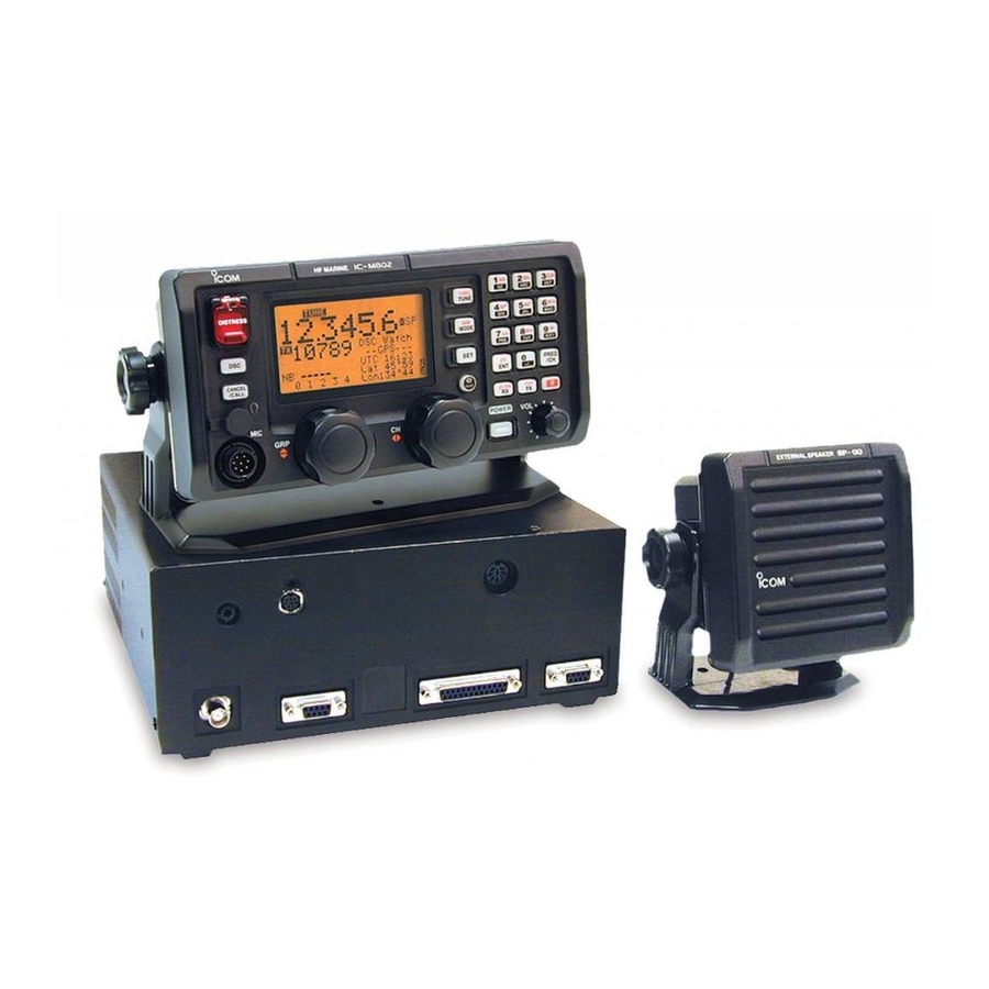
CONNECTION AND INSTALLATION I Supplied accessories The following accessories are supplied with IC-M802. q Microphone (HM-135) …………………………… 1 w External speaker (SP-24) ………………………… 1 e Mounting bracket kit for main unit …………… 1 set r Mounting bracket kit for remote controller (MB-81) ………………………………………………………
-
Page 62: I Rear Panel Connections
To prevent an accidental cable disconnection, partic- ularly for the external speaker and remote control ca- bles, the supplied cable tie may be helpful. q Install the cable tie (base) onto the IC-M802 main unit side panel, or desired place near the main unit. Grounding (see pgs.
-
Page 63: I Ground Connection
I Ground connection The transceiver and antenna tuner MUST have an adequate RF ground connection. Otherwise, the over- all efficiency of the transceiver and antenna tuner in- stallation will be reduced. Electrolysis, electrical shocks and interference from other equipment could also occur.
-
Page 64: I Antenna
See page 61 for pin assignment. D D Non-Icom tuner Some non-Icom tuners may be used with the IC- M802. Please consult your dealer if you wish to con- nect one. With a 50 Ω matched antenna all marine bands can- not be used.
-
Page 65: I Mounting
I Mounting D Mounting location Select a location that provides easy access to the con- troller for navigation safety, has good ventilation and is not subject to sea spray. The controller should be at 90 degrees to your line of sight when operating it. D D Mounting the controller/speaker/main unit CONFECTION AND INSTALLATION CAUTION: KEEP the transceiver and microphone…
-
Page 66: I Using The Optional Mb-75
CONFECTION AND INSTALLATION I Using the optional MB-75 The optional MB-75 flush mount is available for mount- ing the controller and speaker to a flat surface such as an instrument panel. q Using the template on the page 67 for the remote controller (RC-25), and page 69 for the speaker (SP-24), carefully cut a hole into the instrument panel (or wherever you plan to mount the controller…
-
Page 67: I Transceiver Dimensions
CONFECTION AND INSTALLATION I Transceiver dimensions…
-
Page 68: I Fuse Replacement
CONFECTION AND INSTALLATION I Fuse replacement The transceiver has 2 fuses (2 types) to protect inter- nal circuitry, 1 fuse for the fuse holder on the DC power cable and 1 for inside. If the transceiver stops func- tioning, check the fuses below. •…
-
Page 69: I Connector Information
I Connector information Pin Pin name AF GND SEND 13.6 V DC GND MICROPHONE Pin Pin name MIC+ MIC– AF– TUNER Pin Pin name START 13.6V DC 13.6V Pin Pin name 1–3 4–6 CONFECTION AND INSTALLATION Description CW and FSK keying input. Ground line for AF signal.
-
Page 70
CONFECTION AND INSTALLATION I Connector information (continued) AF/MOD Pin Pin name MOD+ MOD– NAF+ NAF– SEND REMOTE Pin Pin name NMEA-OUT NMEA0183 ver. 3.01 data output. (“NMEA” selection for REMOTE IF. (p. 52)) NMEA-IN NMEA0183 ver. 3.01 data input. (“NMEA” selection for REMOTE IF. (p. 52)) Pin Pin name NMEA + NMEA _… -
Page 71: Antenna And Grounding Considerations
GTO-15 wire interconnects the whip to the automatic tuner. The tuner is fed with coax (RG 213) and a control line from the back of the Icom SSB wherever you plan to hide the auto-tuner. Remember, the ICOM automatic tuner is fully au-…
-
Page 72
ANTENNA AND GROUNDING CONSIDERATIONS everything of ground potential. If you can get at your keel bolt, or tap a screw into the keel, your grounding is done. Lead incapsulated keels are the ultimate in grounds, and you may need nothing further. In powerboats, since there’s no keel, you’re going to need to come up with at least 100 square feet of RF ground surface below the water line. -
Page 73
Loran whip. These tuner ground circuits are mandatory for any type of reliable operation. If you try to run an ICOM side- band set with a remote tuner that is undergrounded, you stand the chance of not only burning up your equipment, but also damaging other electronics onboard with stray RF. -
Page 74: Specifications
SPECIFICATIONS • General • Frequency coverage Receive 0.5–29.9999 Transmit 1.6–2.9999 6.0–6.9999 12.0–13.9999 18.0–19.9999 25.0–27.5000 • DSC channels : 2,187.5 kHz, 4,207.5 kHz, 6,312.0 kHz, 8,414.5 kHz, 12,577.0 kHz, 16,804.5 kHz • Type of emission Transceiver (USB/LSB) (FSK) DSC receiver • No. of memory Ch. : 1136 channels (max.) 160 user programmable, 242 ITU SSB duplex, 72 ITU SSB simplex,…
-
Page 75: Template
TEMPLATE I Remote controller (RC-25) ″ 92 mm; 3 ⁄ 4–R11…
-
Page 76: I Speaker (Sp-24)
TEMPLATE I Speaker (SP-24) ″ 92 mm; 3 ⁄ 4–R11…
-
Page 77: Options
Same as that supplied remote with the transceiver. Mounting bracket, MB-81, is supplied with the controller. HM-135 HAND MICROPHONE Same as supplied with the IC-M802. AT-140 AUTOMATIC ANTENNA TUNER Antenna and control cable receptacles for easy installation and tuner through function are available.
-
Page 78
A-6154H-1US-q Printed in Japan © 2002 Icom Inc. Icom America Inc. Icom (Europe) GmbH <Corporate Headquarters> Communication Equipment 2380 116th Avenue N.E., Bellevue, WA 98004, U.S.A. Himmelgeister Str. 100, Phone: (425) 454-8155 Fax: (425) 454-7619 D-40255 Düsseldorf, Germany URL: http//www.icomamerica.com Phone: 0211 346047 URL: http//www.icomeurope.com…
Особенности:
Эта автосигнализация отличается высоким качеством и экономичной производительностью.
Дизайн пульта дистанционного управления позволяет вам иметь в руках идею обеспечения безопасности вашего автомобиля.
Его универсальность подходит для любых типов автомобилей.
Он имеет функции дистанционного оповещения и голосовой подсказки.
Небольшой дизайн и красивая форма
Высокое качество и долговечность в использовании
Легко работать, удобнее и безопаснее
Сильно защиты от воров
Легко установить, не влияет на весь привлекательный внешний вид автомобиля
Технические характеристики:
Рабочее напряжение основного блока: 12 В
Статический ток: 10mA
Светодиодный индикатор: 3mA
Сирена: 10A
Центральный замок: 10A
Рабочая частота: 315-316 МГц
Количество пульта дистанционного управления: 2
Пакет Содержание:
1 х Главный блок управления
2 х пульт дистанционного Управление
1 х светодиодный провод подключения
1 х реле убийцы двигателя
1 х датчик удара
1 х сирена
1 x набор проводов
Скачать
2001 NEW
MF/HF MARINE TRANSCEIVER
iM802
INSTRUCTION MANUAL
IC-M802_USA.qxd 02.7.9 10:58 Page a
-
12.02.2018, 09:42
#1
Icоm IC-M802: Раскрыть на передачу. Порядок выполнения программирования (CS-M802#02 +
Доброго дня! Подскажите порядок выполнения программирования Icоm IC-M802. Необходимо раскрыть по мощности радиостанцию на радиолюбительских КВ диапазонах.
-
12.02.2018, 10:44
#2
Диапазон частот
Rx 0.5–29.9999
Tx 1.6– 2.9999, 4.0– 4.9999, 6.0– 6.9999
8.0– 8.9999, 12.0–13.9999, 16.0–17.9999
18.0–19.9999, 22.0–22.9999, 25.0–27.5000
(в зависимости от версии)
-
12.02.2018, 10:53
#3

Silent Key
-73- Игорь
«Прощённый, но так и не понятый» (c)
-
12.02.2018, 14:24
#4
В настоящее время для раскрытия р/ст. на передачу поступаю следующим образом =перед каждым включением радиостанции одновременно нажимаю и удерживаю следующие кнопки на RC-25 и HM-135 : 2, MODE, PTT.
-
12.02.2018, 15:11
#5
 Сообщение от R0QAD

В настоящее время для раскрытия р/ст. на передачу поступаю следующим образом
Проблему надо решать раз и навсегда.
У мну на судне версия трансивера #11
Решил кардинально..
См. вложение
зип файл — это софт, другой файл — описание действий.
Принцип для Вашей версии тот-же,кажется и интерфейс такой-же.
Сорри, софт Вам не подойдет, по ошибке разместил, ну не удалять же теперь..
Последний раз редактировалось RX3X; 20.08.2021 в 10:40.
73! Илья aka RX3X, bubble gum, ex RA3XE, UA0FBS, W3XXL
«Займитесь же делом каким-нибудь, хватит прожигать ценный невосполнимый ресурс (время) на пустопорожние споры.. На «Чебурашку» сходите чтоли..»(с)RX3X
Мои Альбомы
-
12.02.2018, 15:16
#6
Сообщение от UT3IM
Может это?
Легко послать в гугл..
Я тоже могу послать в …. в яндекс короче..
Ты делом помоги.ПыСы
версия софта для перепрошивки должна совпадать с версией трансивера.
У меня оказалась версия 11, поэтому более ранний софт не работал, как я не бился.. пока не понял проблему, и не нашел необходимую версию.Уж не помню, толи диллер дал, толи шмиллер..
73! Илья aka RX3X, bubble gum, ex RA3XE, UA0FBS, W3XXL
«Займитесь же делом каким-нибудь, хватит прожигать ценный невосполнимый ресурс (время) на пустопорожние споры.. На «Чебурашку» сходите чтоли..»(с)RX3X
Мои Альбомы
-
12.02.2018, 15:35
#7
Сообщение от RX3X
Проблему надо решать раз и навсегда.
Благодарю!!! Пытаюсь разобраться. Вопрос. Как определить версию? Серийный номер №0202641.
-
12.02.2018, 15:37
#8
Silent Key
Сообщение от RX3X
Легко послать в гугл..
Чего-то не то прицепилось. А ведь проверял…

Ладно. Вот что я имел ввиду.-73- Игорь
«Прощённый, но так и не понятый» (c)
-
12.02.2018, 15:44
#9
Сообщение от R0QAD
Вопрос. Как определить версию? Серийный номер №0202641.
Мне привезли нулевые трансиверы, на коробке была версия.
Наверное на шильдике сзади посмотрите, или при включении кажется должна быть версия..
В данный момент посмотреть не смогу, только утром(у меня ночь), это на ходовом мостике надо вытаскивать его из стойки..
Вы же в первом сообщении сказали, что у вас вер.0273! Илья aka RX3X, bubble gum, ex RA3XE, UA0FBS, W3XXL
«Займитесь же делом каким-нибудь, хватит прожигать ценный невосполнимый ресурс (время) на пустопорожние споры.. На «Чебурашку» сходите чтоли..»(с)RX3X
Мои Альбомы
-
12.02.2018, 15:52
#10
Сообщение от UT3IM
Вот что я имел ввиду.
Ты сам читал?
Там программирование морских ITU каналов.. оно ему надо?
Скачай документ в моем вложении, там я специально разжевал для других радистов.
Нам в компанию партию этих канальных айкомов поставили, а раскрытием не озаботились.
Пришлось самому рожать, и разжевывать остальным.
Но получилось все по другому.
В общем, все трансиверы пришлось перепрошивать мне.73! Илья aka RX3X, bubble gum, ex RA3XE, UA0FBS, W3XXL
«Займитесь же делом каким-нибудь, хватит прожигать ценный невосполнимый ресурс (время) на пустопорожние споры.. На «Чебурашку» сходите чтоли..»(с)RX3X
Мои Альбомы
-
12.02.2018, 15:59
#11
Правильно, когда заказывал шнурок и программ обеспечение на sicom.ru указали #02. На самом деле не в курсе. Поэтому задал вопрос, как то так.
-
12.02.2018, 16:02
#12
-
12.02.2018, 16:07
#13
Silent Key
Сообщение от RX3X
Ты сам читал?
Читал. И ты почитай. До конца.
В конце таблицы програмирование любительских частот.-73- Игорь
«Прощённый, но так и не понятый» (c)
-
12.02.2018, 16:10
#14
Значит софт у вас есть.
Устанавливайте его, софт для шнурка(если у вас USB шнурок), и подключайте.
В программе установите тот СОМ порт, какой у вас получился виртуальный СОМ порт.
Все должно работать на раз..
Но там есть еще одно НО.
В софте для перепрошивки кажется есть варианты только для 4-х СОМ портов — СОМ1, СОМ2, СОМ3, СОМ4.
А софт к шнурку (вернее к его микросхеме виртуального СОМ порта), создает порт с номером бОльшим, чем СОМ4, т.е. СОМ9,10,15,25.. и т.д…
Поэтому прилагаемый к моим трансиверам USB шнурок я со злости закинул за переборку.. как ни плясал с бубном, так и не смог поменять номер порта на СОМ1-4.. Ни со стационарным компом, ни с ноутбуком. Не знаю почему. Так иногда случается. Поэтому пришлось мастерить самопал.
Последний раз редактировалось RX3X; 12.02.2018 в 16:20.
73! Илья aka RX3X, bubble gum, ex RA3XE, UA0FBS, W3XXL
«Займитесь же делом каким-нибудь, хватит прожигать ценный невосполнимый ресурс (время) на пустопорожние споры.. На «Чебурашку» сходите чтоли..»(с)RX3X
Мои Альбомы
-
12.02.2018, 16:14
#15
Сообщение от UT3IM
В конце таблицы програмирование любительских частот.
сам программируй
Только перепрограммирование шнурком через софт. Все.
Я все эти программирования частот и каналов проходил.
Облазил весь инет, все радиосканнеры и прочие модс..ПОЛНОСТЬЮ проблема решается только шнурком и софтом.
И не задуривай людям голову.Последний раз редактировалось RX3X; 12.02.2018 в 16:18.
73! Илья aka RX3X, bubble gum, ex RA3XE, UA0FBS, W3XXL
«Займитесь же делом каким-нибудь, хватит прожигать ценный невосполнимый ресурс (время) на пустопорожние споры.. На «Чебурашку» сходите чтоли..»(с)RX3X
Мои Альбомы
-
Icom IC-M802 — page 1
MF/HF MARINE TRANSCEIVER iM802 SER VICE MANU AL …
-
Icom IC-M802 — page 2
INTRODUCTION This ser vice manual describes the latest ser vice information f or the IC-M802 MF/HF MARINE TRANSCEIVER at the time of publication. D ANGER NEVER connect the transceiv er to an A C outlet or to a DC power supply that uses more than 16 V . This will ruin the transceiv er . DO NO T e xpose the transceiv er to rain, sno w or any liquids …
-
Icom IC-M802 — page 3
T ABLE OF CONTENTS SECTION 1 SPECIFICA TIONS SECTION 2 INSIDE VIEWS SECTION 3 CIRCUIT DESCRIPTION SECTION 4 ADJUSTMENT PROCEDURES SECTION 5 P ARTS LIST SECTION 6 MECHANICAL P ARTS AND DISASSEMBL Y 6 — 1 RC-25 …………………………………………………………………………………………………………………………… …
-
Icom IC-M802 — page 4
• IC-M802 ‘ ‘ GENERAL • Frequency coverage : • Mode : TX/RX J3E (USB/LSB), J2B (AFSK), F1B (FSK), A1A (CW) H3E [OTH] RX H3E [USA], [CAN] DSC J2B [USA], [CAN] • Antenna impedance : 50 Ω • Frequency stability : ± 10 Hz [USA], [CAN], ± 20 Hz [OTH] • Power supply requirement : 13.6 V DC ± 15% Negative ground • Current drain (at 1 …
-
Icom IC-M802 — page 5
1 — 2 • RC-25 Remote controller ‘ ‘ GENERAL • Microphone impedance : 600 Ω • Audio output power : More than 5 mW at 16 Ω headphone with 10 % distortion • Audio output impedance : 8 – 16 Ω • Usable temperature range : – 20 ˚ C to +55 ˚ C; – 4 ˚ F to +131 ˚ F • Dimension (projections not included) : 220(W) × 1 10(H) ? …
-
Icom IC-M802 — page 6
SECTION 2 INSIDE VIEWS 2 — 1 • RC-25 • IC-M802 VR BOARD Reset IC (IC8202: S-80942ANMP) CPU (IC8201: HD64F2134AF A20) LCD unit (DS8220: HLC770-018800) P ow er amplifier (IC8270: T A7368F) DISPLA Y BO ARD SENSOR BOARD VR BOARD Reset IC (IC8202: S-80942CNMC) CPU (IC8201: HD64F2134AF A20) LCD unit (DS8220: HLC7700-018800) P ow er amplifier (IC8270: …
-
Icom IC-M802 — page 7
3 — 1 SECTION 3 CIRCUIT DESCRIPTION 3-1 RECEIVER CIRCUITS 3-1-1 RF FI L TER CIRCUIT (FIL TER AND MAIN UNITS) Received signals from the antenna connector are applied to the transmit/receive switching and protection relay (FIL TER unit; RL7301) which is controlled by the CPU via the “ TRXS ” line. The signals pass through the 30 MHz cut-of f low- …
-
Icom IC-M802 — page 8
3 — 2 The level-shifted signal is applied to the DSP IC (IC301) for the digital IF filter , demodulator , automatic notch and noise reduction, etc. The output signal from the DSP IC is applied to the D/A con- verter section in the CODEC IC (IC501) to convert into the analog audio signals. Also the signals are level-shifted 3.3 V to 5 V at the level …
-
Icom IC-M802 — page 9
3 — 3 3-2 TRANSMITTER CIRCUITS 3-2-1 MICROPHONE AMPLIFIER CIRCUIT (RC-25, MAIN AND DSP UNITS) The microphone amplifier circuit amplifies microphone audio signal to a level needed for the DSP circuit. Audio signals from the [MIC] connector (J8701, pin 1) are amplified at the AF amplifier (IC8280, pin 3), and then applied to the gate modulator IC (MA …
-
Icom IC-M802 — page 10
3 — 4 3-2-5 RF CIRCUIT (MAIN, P A UNITS AND DRIVER BOARD) The RF circuit amplifies operating (transmitting) frequency to obtain 150 W of RF output. The signal from the 1st IF mixer is passed through one of the low-pass filter or bandpass filters (Refer to page 4-1 band- pass filters used), and then applied to the YGR amplifier (IC1, pin 1) after be …
-
Icom IC-M802 — page 11
3 — 5 • 14 – 19.9999 MHz signal The signal is applied to the relay (FIL TER unit; RL721 1) which is controlled by the band control IC (MAIN unit; IC3602) as the “ L16M ” signal via the buffer amplifier (MAIN unit; IC1301, pin 17). The signal passes through the low- pass filter (FIL TER unit; L7216 – L7218, C7214, C7216, C7217, C7221 – C …
-
Icom IC-M802 — page 12
3 — 6 3-3 PLL CIRCUITS 3-3-1 GENERAL The PLL circuits generate a reference frequency (32.000 MHz); 1st LO frequencies (64.485 – 94.455 MHz); 2nd LO frequency (64 MHz), 3rd LO frequency (433.000 kHz). The 1st LO PLL adopts a mixer-less dual loop PLL system. The BFO uses a DDS and a 2nd LO as a fixed frequency double that the crystal oscillator . 3 …
-
Icom IC-M802 — page 13
3 — 7 3-4 DSC CIRCUITS ([USA], [CAN] ONL Y) 3-4-1 DSC BANDP ASS FIL TER AND RF AMPLIFIER CIRCUITS (MAIN UNIT) The RF circuit filters out-of-band signals and amplifiers sig- nals within the range of frequency coverage. (1) 2 – 7 MHz signals The signals from the antenna connector (J2101) pass through the bandpass filter (L2201, L2202, L2207, L2210, …
-
Icom IC-M802 — page 14
3 — 8 3-5-3 GROUP AND CHANNEL DIALS CIRCUIT (DISPLA Y AND SENSOR BOARDS) • GROUP DIAL The signals from the group dial (SENSOR board; S8801) is applied to the FRONT CPU (IC8201, pins 76, 77) via the “ GP A ” and “ GPB ” signals. • CHANNEL DIAL The signals from the channel dial (SENSOR board; S8802) is applied to the FRONT CPU (IC8021, pi …
-
Icom IC-M802 — page 15
3 — 9 Pin number 90 92 93 94 97 Port name ECK ASEN TEMP NSEN RFML Description Outputs serial clock signal for the EEPROM (IC3301, pin 6). Input port for the SEND signal from the accessory connector (J1801). Input port for the power amplifier tem- perature signal from the P A unit. Input port for the SEND signal from the AF/MOD connector (PLL unit; …
-
Icom IC-M802 — page 16
3 — 10 3-7-5 OUTPUT EXP ANDER IC (IC3603) Pin number 4 5 6 11 13 14 Port name NMS EMS MMS NMRS AFMS CSEN Description Outputs NBDP MOD control signal for the gate mod IC (IC2001, pin 10). Outputs external MOD control signal for the gate mode IC (IC2001, pin 1 1). Outputs microphone MOD control sig- nal for the gate mode IC (IC2001, pin 9). Outputs N …
-
Icom IC-M802 — page 17
3 — 1 1 3-7-8 FRONT CPU PORT ALLOCA TIONS (RC-25, DISPLA Y BOARD; IC8201) Pin number 17 21 22 23 24 25 26 28 31 32 33 34 35 36 41 – 46 48 – 55 57 58 59 60 61 62 63 64 65 66 67 68 69 70 71 72 Port name DSEL FUNK TXK RXK FCHK T0K ENTK PWRK PMUT FPTT AFGL M1AD M2AD M3AD CL1 RS RD WR RES CS DB7 – DB0 T9K T8K T7K T6K T5K T4K T3K T2K T1K EMLK SETK …
-
Icom IC-M802 — page 18
4 — 1 4-1 PREP ARA TION When adjusting the contents on page 4-9, a JIG CABLE (see illustration as shown below) is required. Some adjustments must be performed on the “ ADJUSTMENT MODE ” . Entering the “ ADJUSTMENT MODE ” , see the next page. ■ REQUIRED TEST EQUIPMENT SECTION 4 ADJUSTMENT PROCEDURES EQUIPMENT DC power supply RF power meter …
-
Icom IC-M802 — page 19
■ ENTERING THE ADJUSTMENT MODE 1 T urn the power OFF . 2 Push and hold the HM-135’s [DOWN] key , [TX] and [RX] buttons, then turn the power ON. NOTE: Inserting the 15 k Ω resistor between 2 pin and 6 pin of HM-135 works same as pushing and holding HM-135 ’ s [DOWN] key (See the illustration on page 4-1). ■ OPERA TING ON THE ADJUSTMENT MOD …
-
Icom IC-M802 — page 20
4 — 3 4-2 PLL UNIT ADJUSTMENT LPL LOCK VOL T AGE HPL LOCK VOL T AGE REFERENCE FREQUENCY 1 2 1 2 1 2 • Operating frequency : 0.5000 MHz • Mode : J3E • Receiving • Operating frequency : 0.4999 MHz • Receiving • Operating frequency : 29.9999 MHz • Mode : J3E • Receiving • Operating frequency : 0.0300 MHz • Receiving • W ait for 5 …
-
Icom IC-M802 — page 21
4 — 4 HPL lock v oltage chec k point CP5401 C5394 Ref erence frequency adjustment (USA, CAN) X5251 LPL lock v oltage chec k point CP5301 Ref erence frequency check point P5201 LPL lock v oltage adjustment C5305 LPL lock v oltage adjustment L5203 L5204 Ref erence frequency adjustment (O TH) C5521 HPL lock v oltage adjustment • PLL UNIT T OP VIEW P …
-
Icom IC-M802 — page 22
4 — 5 4-3 P A AND FIL TER UNITS ADJUSTMENT IDLING CURRENT (For drive FET s) (For final transistors) SWR DETECTOR 1 2 • Operating frequency : 12.2350 MHz • Mode : J3E • Apply no audio signal to the [MICRO- PHONE] connector . • Disconnect J6702. • Preset R6304 and R6412 on the P A unit to max. counter clockwise. • Connect a dummy load or …
-
Icom IC-M802 — page 23
SWR detector check point CP7331 (REF line) Connect to ground CP7332 (FOR line) SWR detector adjustment C7275 4 — 6 R6304 Idling current adjustment (F or drive FETs) R6412 Idling current adjustment (F or final transistors) • IC-M802 TOP VIEW • FIL TER UNIT BOTTOM VIEW FIL TER unit • IC-M802 BOTTOM VIEW …
-
Icom IC-M802 — page 24
4-4 RECEIVER ADJUSTMENTS ” TOT AL GAIN ” , “ S-METER ” and “ DSC PEAK ” adjustments must be performed at “ ADJUSTMENT MODE ” . NOISE NULL POINT RECEIVER GAIN TOT AL GAIN S-METER DSC PEAK ([USA],[CAN] only) DSC SELF CHECK ([USA],[CAN] only) 1 1 1 1 2 1 1 • Operating frequency : 0.5 MHz • Mode : H3E • Preset L402 and L405 to max …
-
Icom IC-M802 — page 25
4 — 8 L307 Receiver gain adjustment Noise null point adjustment L302 L208 L209 L301 L210 L207 DSC peak adjustment L2307 L2306 [ENT] • IC-M802 TOP VIEW • RC-25 FRONT P ANEL …
-
Icom IC-M802 — page 26
4 — 9 4-5 TRANSMITTER ADJUSTMENTS The following adjustments must be performed at “ ADJUSTMENT MODE ” after “ SWR DETECTOR ” and “ RECEIVER ” ADJUST- MENTS in the SECTION 4-3 and 4-4. TRANSMIT PEAK AND TOT AL GAIN (TX PEAK) (TOT AL GAIN) TX POWER (HIGH) (MIDDLE) (LOW) TUNE POWER AM CARRI- ER POWER ([OTH] only) 1 2 1 2 1 2 1 2 1 2 1 2 • …
-
Icom IC-M802 — page 27
[CH] [ENT] T ransmit peak and total gain adjustment L706 R6516 Ic-APC adjustment J3101 pin 15 Connect to ground when adjusting IC-APC 4 — 10 • IC-M802 TOP VIEW • RC-25 FRONT P ANEL TRANSMITTER ADJUSTMENTS(CONTINUE) 1 • Operating frequency : 12.2350 MHz • Mode : J3E • Set the audio generator as: Frequency : 1.5 kHz Level : 100 mV • Prese …
-
Icom IC-M802 — page 28
[MAIN UNIT] 5-1 IC-M802 [MAIN UNIT] IC1 1 1 10004080 S.IC µPC2709T-E3 IC501 1 1 10005460 S.IC T A4107F (TE12L) IC901 1 1 10005460 S.IC T A4107F (TE12L) IC1001 1 130006220 S.IC TC4W53FU (TE12L) IC1002 1 1 10005450 S.IC TS522IDT IC1051 1 1 10005450 S.IC TS522IDT IC1 101 1 1 10005450 S.IC TS522IDT IC1201 1 1 10005140 S.IC NJM3403A V-TE1 IC1301 1 1600 …
-
Icom IC-M802 — page 29
[MAIN UNIT] [MAIN UNIT] S.=Surface mount L55 6200002040 S.COIL NL 252018T-101J L56 6200002040 S.COIL NL 252018T-101J L101 6200003940 S.COIL NL 252018T-5R6J L102 6200002860 S.COIL NL 252018T-4R7J L103 6200002040 S.COIL NL 252018T-101J L104 6200003280 S.COIL NL 252018T-2R2J L105 6200002040 S.COIL NL 252018T-101J L106 6200009860 S.COIL NL 252018T-1R5J …
-
Icom IC-M802 — page 30
S.=Surface mount [MAIN UNIT] [MAIN UNIT] L2702 6200003520 S.COIL ELJFB 102K-F [USA], [CAN] L2703 6200002040 S.COIL NL 252018T -101J [USA], [CAN] L3301 6200000970 S.COIL NL 322522T-100K L3601 6200003950 S.COIL HF50ACC 322513-T L3602 6200003950 S.COIL HF50ACC 322513-T R1 7030003270 S.RESISTOR ERJ3GEYJ 390 V (39 Ω ) R2 7030003340 S.RESISTOR ERJ3GEYJ …
-
Icom IC-M802 — page 31
[MAIN UNIT] [MAIN UNIT] S.=Surface mount R1222 7030003240 S.RESISTOR ERJ3GEYJ 220 V (22 Ω ) R1223 7030003480 S.RESISTOR ERJ3GEYJ 222 V (2.2 k Ω ) R1224 7030003320 S.RESISTOR ERJ3GEYJ 101 V (100 Ω ) R1225 7030003320 S.RESISTOR ERJ3GEYJ 101 V (100 Ω ) R1226 7030003360 S.RESISTOR ERJ3GEYJ 221 V (220 Ω ) R1228 7030003440 S.RESISTOR ERJ3GEYJ 1 …
-
Icom IC-M802 — page 32
S.=Surface mount [MAIN UNIT] [MAIN UNIT] R2708 7030003440 S.RESISTOR ERJ3GEYJ 102 V (1 k Ω ) [USA], [CAN] R2709 7030003320 S.RESISTOR ERJ3GEYJ 101 V (100 Ω ) [USA], [CAN] R2710 7030003320 S.RESISTOR ERJ3GEYJ 101 V (100 Ω ) [USA], [CAN] R271 1 7030003440 S.RESISTOR ERJ3GEYJ 102 V (1 k Ω ) [USA], [CAN] R2712 7030003440 S.RESISTOR ERJ3GEYJ 102 …
-
Icom IC-M802 — page 33
[MAIN UNIT] [MAIN UNIT] S.=Surface mount C62 4030006870 S.CERAMIC C1608 JB 1H 222K-T C63 4030008860 S.CERAMIC C1608 JB 1H 153K-T C64 403001 1600 S.CERAMIC C1608 JB 1E 104K-T C65 403001 1600 S.CERAMIC C1608 JB 1E 104K-T C66 403001 1600 S.CERAMIC C1608 JB 1E 104K-T C67 403001 1600 S.CERAMIC C1608 JB 1E 104K-T C68 403001 1600 S.CERAMIC C1608 JB 1E 104 …
-
Icom IC-M802 — page 34
S.=Surface mount [MAIN UNIT] [MAIN UNIT] C707 4030006970 S.CERAMIC C1608 CH 1H 060D-T C709 4030007080 S.CERAMIC C1608 CH 1H 390J-T C710 4030007040 S.CERAMIC C1608 CH 1H 180J-T C71 1 4030007050 S.CERAMIC C1608 CH 1H 220J-T C712 403001 1600 S.CERAMIC C1608 JB 1E 104K-T C714 403001 1600 S.CERAMIC C1608 JB 1E 104K-T C715 4030006960 S.CERAMIC C1608 CH 1 …
-
Icom IC-M802 — page 35
[MAIN UNIT] [MAIN UNIT] S.=Surface mount C2104 403001 1600 S.CERAMIC C1608 JB 1E 104K-T [USA], [CAN] C2105 4030008920 S.CERAMIC C1608 JB 1H 473K-T [USA], [CAN] C2106 4030008680 S.CERAMIC C2012 JF 1C 105Z-T [USA], [CAN] C2107 403001 1600 S.CERAMIC C1608 JB 1E 104K-T [USA], [CAN] C2201 403001 1600 S.CERAMIC C1608 JB 1E 104K-T [USA], [CAN] C2202 40300 …
-
Icom IC-M802 — page 36
S.=Surface mount [PLL UNIT] [MAIN UNIT] EP1 0910054676 PCB B 5722F EP2 0880000900 UNIT BOARD EX-2432 #02 [USA], [CAN] 0880001 190 UNIT BOARD EX-2432 #03 [OTH] IC5001 1 180001070 S.IC T A7805F (TE16L) IC5031 1 180001250 S.IC T A7808F (TE16L) IC5081 1 120002920 S.IC ADM202EARN IC5082 1 130006800 S.IC TC7W08F (TE12L) IC5083 1 130007040 S.IC TC7W32F (T …
-
Icom IC-M802 — page 37
[PLL UNIT] [PLL UNIT] S.=Surface mount R51 13 7030007210 S.RESISTOR ERA3YEB 102V R51 14 7030007210 S.RESISTOR ERA3YEB 102V R51 15 7030007210 S.RESISTOR ERA3YEB 102V R51 16 7030007210 S.RESISTOR ERA3YEB 102V R51 17 7030007210 S.RESISTOR ERA3YEB 102V R51 18 7030007230 S.RESISTOR ERA3YED 102V R51 19 7030007230 S.RESISTOR ERA3YED 102V R5120 7030007230 …
-
Icom IC-M802 — page 38
S.=Surface mount [PLL UNIT] [PLL UNIT] R5901 7030007220 S.RESISTOR ERA3YED 202V [USA], [CAN] R5902 7030007230 S.RESISTOR ERA3YED 102V [USA], [CAN] R5903 7030007230 S.RESISTOR ERA3YED 102V [USA], [CAN] R5904 7030007230 S.RESISTOR ERA3YED 102V [USA], [CAN] R5905 7030007230 S.RESISTOR ERA3YED 102V [USA], [CAN] R5906 7030007230 S.RESISTOR ERA3YED 102V …
-
Icom IC-M802 — page 39
[PLL UNIT] [PLL UNIT] S.=Surface mount C5705 4030006880 S.CERAMIC C1608 JB 1H 472K-T C5706 4030006880 S.CERAMIC C1608 JB 1H 472K-T C5707 4030006880 S.CERAMIC C1608 JB 1H 472K-T C5708 4510005600 S.ELECTROL YTIC ECEV1CS100SR C5709 4030006880 S.CERAMIC C1608 JB 1H 472K-T C5710 4030006860 S.CERAMIC C1608 JB 1H 102K-T C571 1 4030007010 S.CERAMIC C1608 C …
-
Icom IC-M802 — page 40
S.=Surface mount [P A UNIT] [P A UNIT] R6403 7030010260 S.RESISTOR ERJ1TYJ 3R3 U R6404 7030010260 S.RESISTOR ERJ1TYJ 3R3 U R6405 7030010260 S.RESISTOR ERJ1TYJ 3R3 U R6406 7030010260 S.RESISTOR ERJ1TYJ 3R3 U R6407 7030001010 S.RESISTOR MCR50JZHJ 10 Ω (100) R6408 7030001010 S.RESISTOR MCR50JZHJ 10 Ω (100) R6409 7070000371 RESISTOR ERX2SJ 2R2 (2.2 …
-
Icom IC-M802 — page 41
[FIL TER UNIT] [FIL TER UNIT] S.=Surface mount Q7301 1590000680 S.TRANSISTOR DTC1 14EUA T106 D7271 1750000190 S.DIODE 1SS322 (TE85R) D7272 1750000190 S.DIODE 1SS322 (TE85R) D7301 1750000550 S.DIODE 1SS355 TE-17 L7031 6200002040 S.COIL NL 252018T-101J L7035 6200002040 S.COIL NL 252018T-101J L7036 6140002830 COIL LR-236 L7037 6140002950 COIL LR-226 L …
-
Icom IC-M802 — page 42
S.=Surface mount [DRIVER UNIT] [FIL TER UNIT] C7218 4030006880 S.CERAMIC C1608 JB 1H 472K-T C7221 4030014460 S.CERAMIC GRM31M2C2H820JV01L C7222 4010005860 CERAMIC HM95SJ SL 201J 500V C7223 4030014460 S.CERAMIC GRM31M2C2H820JV01L C7224 403001 1210 S.CERAMIC GRM31M2C2H330JV01L C7225 403001 1 190 S.CERAMIC GRM31M2C2H270JV01L C7241 4030006880 S.CERAMIC …
-
Icom IC-M802 — page 43
[DSP UNIT] EX-2432 [DSP UNIT] S.=Surface mount IC1 1 130010010 S.IC TC7WHU04FU IC3 1 130010540 S.IC SN74AHC74PWR IC4 1 130010540 S.IC SN74AHC74PWR IC51 1 130010010 S.IC TC7WHU04FU IC101 1 130010520 S.IC SN74HCT244APWR IC102 1 1 10004770 S.IC BU9480F-E2 IC152 1 180002320 S.REG TK1 1218CMCL IC161 1 180002020 S.REG BA033FP-E2 IC171 1 180002270 S.REG T …
-
Icom IC-M802 — page 44
S.=Surface mount [DSP UNIT] [DSP UNIT] C54 4030006900 S.CERAMIC C1608 JB 1H 103K-T C101 403001 1600 S.CERAMIC C1608 JB 1E 104K-T C102 4510004630 S.ELECTROL YTI C ECEV1CA100SR C103 403001 1600 S.CERAMIC C1608 JB 1E 104K-T C104 4510004630 S.ELECTROL YTIC ECEV1CA100SR C154 403001 1600 S.CERAMIC C1608 JB 1E 104K-T C155 403001 1600 S.CERAMIC C1608 JB 1E …
-
Icom IC-M802 — page 45
[DISPLA Y UNIT] RC-25 [FRONT UNIT] S.=Surface mount W8001 8900009531 CABLE OPC-942A (P=1 N=10 L=170) W8005 8900008860 CABLE OPC-875 (N:20 L:70) IC8201 1 140010640 S.IC HD64F2134AF A20 (SX-2429B) IC8202 1 1 10005770 S.IC S-80942CNMC-G9C-T2 IC8250 1 130005720 S.IC TC7W04F (TE12L) IC8260 1 130007350 S.IC TC74HC4066AF IC8270 1 1 10001810 S.IC T A7368F …
-
Icom IC-M802 — page 46
S.=Surface mount [DISPLA Y UNIT] [DISPLA Y UNIT] C8206 4030007020 S.CERAMIC C1608 CH 1H 120J-T C8207 4030007020 S.CERAMIC C1608 CH 1H 120J-T C8208 403001 1600 S.CERAMIC C1608 JB 1E 104K-T C8209 4030006900 S.CERAMIC C1608 JB 1H 103K-T C8210 4030006880 S.CERAMIC C1608 JB 1H 472K-T C821 1 4030006880 S.CERAMIC C1608 JB 1H 472K-T C8212 4030006880 S.CERA …
-
Icom IC-M802 — page 47
HM-135 [MAIN UNIT] [VR UNIT] S.=Surface mount R8901 7210002360 V ARIABLE TP96N97-15F-10KB-1301 EP8901 0910054742 PCB B 5730B L8220 6200001830 S.COIL NL 322522T-100J L8221 6200001830 S.COIL NL 322522T-100J R8241 7030003830 S.RESISTOR ERJ3GEYJ 185 V (1.8 M Ω ) R8242 7030003840 S.RESISTOR ERJ3GEYJ 225 V (2.2 M Ω ) R8243 7030003640 S.RESISTOR ERJ3G …
-
Icom IC-M802 — page 48
6-1 RC-25 6-2 SP-24 6-3 HM-135 [CHASSIS P ARTS] J4501 6510000370 Connector MR-DS 1 J4503 6510000370 Connector MR-DS [USA],[CAN] only 1 W4501 8900011050 Cable OPC-1109 1 W4502 8900011060 Cable OPC-1141 1 W4505 8900011220 Cable OPC-1143 1 W4506 8900008880 Cable OPC-877 1 W4507 8900011230 Cable OPC-1142 1 W4528 8900011030 Cable OPC-1130 1 MF4501 27100 …
-
Icom IC-M802 — page 49
[MAIN UNIT] J1451 6450000140 Connector HSJ0807-01-010 1 J1801 6510023670 Connector TCS4480-01-4151 1 J2051 6510023180 Connector TCS7282-01-211 1 EP2 0880000900 DSP board [USA],[CAN] 1 0880001190 DSP board [O TH] 1 MP201 8510014610 2429 MIX case 1 MP202 8930005320 Filter spacer (for FI201) 1 MP231 8930005200 Sheet for crystal (for FI231) [USA],[CAN] …
-
Icom IC-M802 — page 50
Unit abbreviations (F): FR ONT P ARTS (D): DISPLA Y BOARD (J): JACK BO ARD (S): SENSOR BOARD (V): VR BOARD (C): CONNECT BOARD RC-25 MP8020 (F) J8602 (J) J8061 (J) MP8022 (F) MP8022 (F) W8005 (F) W8001 (F) MP8002 (F) MP8201 (D) JA CK BOARD J8702 (D) J8701 (D) S8801 (S) MP8006 (F) SENSOR BO ARD VR BO ARD DISPLA Y BO ARD S8802 (S) R8901 (V) MP8005 (F) …
-
Icom IC-M802 — page 51
6 — 4 MP6 (C) MP5 (C) MC1 (M) MP14 (C) MP8 (C) MP9 (C) MP11 (C) MP4 (C) W1 (C) MP7 (C) MP9 (C) MP1 (C) MP12 (C) MP7 (C) SP1 (C) MP1 (C) MP8 (C) MP2 (C) MF4501 (C) MP4512 (C) MP4504 (C) MP4511 (C) EP1 (C) W1 (C) MAIN BO ARD SW BO ARD MAIN UNIT DRIVER BO ARD P A UNIT FIL TER BO ARD PLL UNIT V ARIST OR-1 BO ARD V ARIST OR-2 BO ARD MP2 (C) MP13 (C) MP1 …
-
Icom IC-M802 — page 52
7 — 1 SECTION 7 SEMI-CONDUCT OR INFORMA TION • TRANSIST OR AND FET’S B E C B C E B E C B C E B E C B E C B E C B E C B C E B E C B E C B C E B C E D G S S D G S G D G G S D S G1 G2 S D B E C B E C 2SA1037AK S 2SA1213 Y 2SA1586 GR 2SC2873 Y 2SC4116 BL 2SC4116 GR 2SC4213 B 2SC4215 O 2SC4673 D TD 2SD1585 K 2SD1619 T TD 2SD1664 T100Q 2SK210 GR 2SK5 …
-
Icom IC-M802 — page 53
to IC-M802 MAIN unit J2051 J8602 H13V TXD RXD F AFG FA F GND FMOD FMODG 8 — 1 SECTION 8 BO ARD LA Y OUTS 8-1 HM-135 8-1-1 SW BO ARD • T OP VIEW 8-1-2 MAIN BO ARD • T OP VIEW PTT GND PTT UP DN P SW MOD 8-2 RC-25 8-2-1 JA CK BO ARD • T OP VIEW 8-2-2 CONNECT BO ARD • T OP VIEW 8-2-3 SENSOR BO ARD • T OP VIEW to DISPLA Y board GRP CH …
-
Icom IC-M802 — page 54
H13V TXD RXD F AFG FA F GND FMOD FMODG FMOD 91 to DISPLA Y board J8903 10 2 J8601 GND F AFG TXD GND FMODG FA F H13V RXD GND VO L to DISPLA Y board 8 — 2 8-2-4 VR BO ARD • BO TT OM VIEW (JA CK BO ARD) • BO TT OM VIEW (CONNECT BO ARD) 9V 1 19 2 20 to DISPLA Y board J8205 J8220 GND CL1 CS WR GND DB0 DB2 DB4 DB6 5V GND RES RS RD GND DB1 DB3 DB5 DB7 …
-
Icom IC-M802 — page 55
8-2-5 DISPLA Y BO ARD • T OP VIEW MICE MIC J8701 PTTE MISW AFE PTT AF1 AF2 DISTRESS CLAR/RX THR U/TUNE CANSEL /CALL HEAD PHONE SET/MODE TXF/TX FREQ/CH 0/DIM CE ENT 8/Mid 7/Lo 9/Hi 5/A GC 4/SP 6/RF-G 2/SQL 1/NB e-mail F DSC MIC 3/SCAN 8 — 3 …
-
Icom IC-M802 — page 56
• BO TT OM VIEW (DISPLA Y BO ARD) W8702 [CAN] [USA],[OTH] GND 19 21 0 J8902 GND FZMD FZRS FZRX GND NC NC FZTX FZ5V 1 9 2 10 to JA CK board J8601 J8903 GND RXD H13V FA F FMODG GND TXD F AFG GND FMOD 1 19 2 to CONNECT board J8220 20 J8205 DB7 DB5 DB3 DB1 GND RD RS RES GND 5V DB6 DB4 DB2 DB0 GND WR CS CL1 GND 9V 1 1 14 85 4 8 5 7 14 8 1 20 60 41 21 …
-
Icom IC-M802 — page 57
8 — 5 8-3 IC-M802 8-3-1 DSP BO ARD • T OP VIEW 1 8 16 9 1 10 20 11 1 7 14 8 1 4 8 5 1 36 108 73 72 37 109 144 1 4 8 5 1 14 28 15 1 3 6 4 1 3 6 4 …
-
Icom IC-M802 — page 58
8 — 6 • BO TT OM VIEW (DSP BO ARD) 1 21 to MAIN unit J1102 2 22 J901 DSPI1 GND GND GND 8V GND AGC 2 GND DSPO1 GND GND GND GND DSPI2 GND 8V GND AGC1 GND GND GND DSPO2 29 1 MAIN unit J1101 30 2 DRES KEYIN GND1 OUT7 OUT5 OUT3 OUT1 GND1 OBSY RQO GND1 CK RQI GND1 GND1 GND1 UNLK GND1 OUT8 OUT6 OUT4 OUT2 GND1 STBO DO GND1 DI IBSY GND1 192K 30 2 to MAIN …
-
Icom IC-M802 — page 59
[USA],[CAN] only [USA],[CAN] only [USA],[CAN] only [USA],[CAN] only [OTH] only [USA],[CAN] only [OTH] only 1 3 6 4 1 18 16 9 9 18 10 1 30 80 51 31 50 100 81 1 7 14 8 1 1 8 16 9 9 18 10 1 1 14 85 4 8 5 4 8 5 1 4 58 1 1 91 6 81 1 1 4 5 8 4 8 5 4 85 8 16 9 14 85 1 1 9 18 10 8 16 9 1 8 16 9 1 4 5 8 1 1 14 85 4 8 5 1 1 8 16 9 4 85 4 8 5 1 4 5 8 1 5 10 6 …
-
Icom IC-M802 — page 60
• BO TT OM VIEW (MAIN UNIT) 8 — 8 …
-
Icom IC-M802 — page 61
from CHASSIS J4501 ANT to MAIN unit J51 MRX P7321 to P A unit J6401 FLIN P7001 TRXS 1 15 2 16 to MAIN unit J1301 J7331 L22M L12M L6M L2M GND REF FOR S13V L16M L8M L4M L1M GND GND GND 8-3-3 FIL TER BO ARD • T OP VIEW 8 — 9 …
-
Icom IC-M802 — page 62
• BO TT OM VIEW (FIL TER BO ARD) 8 — 10 …
-
Icom IC-M802 — page 63
[OTH] [USA],[CAN] R5207 [OTH] L5201 [OTH] only [OTH] only [USA],[CAN] only [USA],[CAN] only [USA],[CAN] only [USA],[CAN] only [USA],[CAN] only [USA],[CAN] only 34 34 12 11 1 23 33 22 34 34 12 11 1 23 33 22 18 16 9 14 65 14 85 44 34 33 23 1 11 12 22 1 100 76 26 50 25 75 51 1 8 16 9 51 6 9 J5081 NC DTR GND DTR PXRXD PCTXD 51 6 9 J5051 GND NSEND NC GN …
-
Icom IC-M802 — page 64
1 4 8 5 1 4 J6703 to CHASSIS W4502 KEY ST ART 13.6 ANTC/GND 4 1 J6301 to DRIVER board GND GND DR VI DR VI 1 4 J6302 to DRIVER board DR V O DR V O GND GND 1 3 J6411 to V ARIST OR-1 board GND VA R O VA R I 1 3 to V ARIST OR-2 board J6412 GND GND VA R O 3 1 to F AN J6501 GND NC FA N + T8V 1 19 2 20 J6701 to MAIN unit J1901 GND GND GND ANTC KEYS S13V S …
-
Icom IC-M802 — page 65
8-3-6 DRIVER BO ARD • T OP VIEW 8 — 13 GND VA R O VA R I to P A unit J6411 8-3-7 V ARIST OR-1 BO ARD …
-
Icom IC-M802 — page 66
DR VI DR VI GND GND to P A unit J6301 GND GND DR V O DR V O to P A unit J6302 • BO TT OM VIEW (DRIVER BO ARD) 8 — 14 GND GND VA R O to P A unit J6412 8-3-8 V ARIST OR-2 BO ARD …
-
Icom IC-M802 — page 67
9 — 1 SECTION 9 BLOCK DIA GRAM TX RX COMMON Bus line [USA],[CAN] only [USA],[CAN] only 1.8V REG 3.3V REG +5 REG IC152 TK11218CM IC-161 BA033FP IC171 TK11250CM 8V 5V 3.3V 1.8V DIFF CONV DIFF CONV A/D A/D DIFF CONV IC601 BA15532F DIFF CONV LATCH IC406 SN74AHC74PW IC404 SN74AHCT374PW LATCH IC405 BU4021BF PARA -SERI IC401 SN74AHC595PW SERI -PARA ROM IC …
-
Icom IC-M802 — page 68
10 — 1 SECTION 10 WIRING DIA GRAM P5601 J5601 M1LO P5201 J5201 M2LO P5801 J5801 D1LO AF/MOD AF — GND AF+ NSEND GND NC MOD — MOD+ GND GND NC DTR PXRXD PCTXD J5051 [USA],[CAN] only [USA],[CAN] only 1 6 2 7 3 8 4 9 5 REMOTE J5081 2 1 7 6 3 8 4 9 5 J5091 GPS GND CHASSIS W4528 MSEN DSAF DSAFE DSMD DSMDE GND NC D0 D1 D2 D3 D4 D5 D6 D7 A16 NC NC NC H5V RX …
-
Icom IC-M802 — page 69
11 — 1 SECTION 11 V OL T A GE DIA GRAMS 11-1 RC-25 and HM-135 C8218 10 1 2 3 4 5 6 7 8 J8701 MIC C8222 0.0047 R8701 33 [USA],[OTH] R8702 33 [USA],[OTH] PMUT PHE PHO L8701 10 µ R8703 100k C8219 10 R8704 100 DSTK CSCK DALK TUNK MODK SETK EMLK T1K T2K T3K T4K T5K T6K T7K T8K T9K ENTK T0K FCHK RXK TXK FUNK DISTRESS /CALL/ALM DSC/CALL /CHO/SELCALL CANC …
-
Icom IC-M802 — page 70
11 — 2 11-2 IC-M802 11-2-1 MAIN UNIT (1) e 8V g f d c b a T8 HV13 RXS T8 T8 R8 R13V 8V 5V 5V — 5V S13V R8 R8 0.1 C1315 T8 T8 HV13 HV13 0.1 C2003 1k R2003 4.7 C2004 S13V POCV R13V R8 DSC ANT DSC ANT FMODG FAFG S13V S13V R8 SPE SPO 0.1 C1905 C2007 0.1 (2) UNIT MAIN 470 R1606 LA4425A IC1601 3 2 1 5 4 33 R1501 220 R705 220 R202 47p C124 330p C173 220 R …
-
Icom IC-M802 — page 71
11 — 3 11-2-2 MAIN UNIT (2) h 4 8 RXS e DAGC ICA 1k R1057 4 8 RXS DSPO2 T8 MAGC T8 R8 4 8 27k R503 0.1 C403 2SA1586 Q1203 MAGC g f d c b a 8.2M R1232 0.0047 C805 FOR (3) UNIT MAIN 0.1 C2254 18p C2251 4.7 R2303 100 R2710 100 R2709 10 C2710 GND V+ TS522ID IC2702 10 C2711 100 R1109 100 R1110 10 C1101 0.1 C1102 TS522ID IC1101 V+ GND 4 8 4 8 470 R1703 1 …
-
Icom IC-M802 — page 72
11 — 4 11-2-3 MAIN UNIT (3) h H5V 10k R3315 NMR UNLK DRES LSTB MSTB LDAT LCK FNCO PODN TRVS TXVS USAS STMD GENE 8V S13V H5V 5V R3340 220 DRES PTMP1 ECK ESIO H5V W1102 W1101 H5V 8V 5V S13V DAGC ASEN NSEN 47k R3903 INITIAL M30624FGAFP [USA],[CAN] M30620FCAFP [OTH] IC3303 P97 AVCC VREF P100/AN0 AVSS P101/AN1 P102/AN2 P103/AN3 P104/AN4/KI0 P105/AN5/KI1 …
-
Icom IC-M802 — page 73
11 — 5 11-2-4 P A UNIT from MAIN unit J1 J6702 YGR to MAIN unit J1901 PON HV HV FANC S13V S13V S13V S13V S13V KEYS STAT ANTC ICV GND GND GND J6701 KEY START 13.6 ANTC/GND J6703 FAN+ GND J6501 GND GND GND GND EP6602 HV13V HV13V HV13V HV13V EP6603 to CHASSIS W4501 from FILTER board J7001 J6401 FLIN R6110 39 C6202 0.1 Q6851 PD55015 DRVO GND J6302 GND …
-
Icom IC-M802 — page 74
11 — 6 11-2-5 PLL UNIT (1) AF/MOD to MAIN unit J3602 AF — GND AF+ NSEND GND MOD — GND MOD+ R5901 2k R5902 1k R5903 1k R5904 1k R5905 1k R5906 1k R5907 1k R5908 1k R5909 1k R5910 1k R5911 2k R5912 2k R5913 2k R5914 2k R5915 2k R5916 2k R5917 2k R5918 2k R5919 2k R5920 2k C5902 0.0047 R5922 100 R5921 1M IC5902 TC7SU04F C5906 0.0047 C5903 0.0047 C5901 …
-
Icom IC-M802 — page 75
11 — 7 11-2-6 PLL UNIT (2) C5802 0.0047 R5820 2k R5819 2k R5818 2k R5817 2k R5816 2k R5815 2k R5814 2k R5813 2k R5812 2k R5810 1k R5809 1k R5808 1k R5807 1k R5806 1k R5805 1k R5804 1k R5803 1k R5802 1k R5811 2k R5801 2k R5822 100 R5821 1M IC5802 TC7SU04F C5806 0.0047 C5803 0.0047 C5801 0.0047 C5805 0.0047 C5807 0.0047 C5808 10 C5804 0.0047 PDAT PCK …
-
Icom IC-M802 — page 76
11 — 8 1 1-2-7 DSP BOARD TMS320VC33PGEA120 IC301 1 A20 2 VSS 3 A19 4 A18 5 A17 6 DVDD 7 A16 8 A15 9 VSS 10 A14 11 A13 12 CVDD 13 A12 14 A11 15 DVDD 16 A10 17 A9 18 VSS 19 A8 20 A7 21 A6 22 A5 23 DVDD 24 A4 25 VSS 26 A3 27 A2 28 CVDD 29 A1 30 A0 31 DVDD 32 PAGE3 33 PAGE2 34 VSS 35 PAGE1 36 PAGE0 37 DVDD 38 H1 39 H3 40 VSS 41 STRB 42 R/W 43 DVDD 44 I …
-
Icom IC-M802 — page 77
11 — 9 11-2-8 FIL TER BO ARD C7035 470p C7038 270p C7049 180p C7042 390p RL7032 AJS1315 C7067 270p C7075 330p C7081 120p RL7062 AJS1315 C7094 330p C7106 150p C7100 100p RL7092 AJS1315 C7127 120p C7131 5p RL7122 AJS1315 C7156 10p RL7152 AJS1315 C7184 120p C7186 56p C7188 22p RL7182 AJS1315 C7224 33p RL7212 AJS1315 C7254 22p C7242 100p RL7242 AJS1315 …
-
Icom IC-M802 — page 78
Asia Icom Inc. 6F No.68, Sec. 1 Cheng-T eh Road, T aipei, T aiwan, R.O.C. Phone : +886 (02) 2559 1899 Fax : +886 (02) 2559 1874 URL : http://www .asia-icom.com E-mail : sales@asia-icom.com Zac de la Plaine, 1, Rue Brindejonc des Moulinais BP 5804, 31505 T oulouse Cedex, France Phone : +33 (5) 61 36 03 03 Fax : +33 (5) 61 36 03 00 URL : http://www . …
-
Icom IC-M802 — page 79
1-1-32, Kamiminami, Hirano-ku, Osaka 547-0003, Japan S-13901HZ-C1- 2 C 2002, 2003 Icom Inc. …