-
Contents
-
Table of Contents
-
Bookmarks
Quick Links
VDS Series PC Oscilloscopes
User Manual
WWW.OWON.COM.HK
Related Manuals for Owon VDS Series
Summary of Contents for Owon VDS Series
-
Page 1
VDS Series PC Oscilloscopes User Manual WWW.OWON.COM.HK… -
Page 2
The information in this manual will replace all that in the materials published originally. The information in this manual was correct at the time of printing. However, OWON will continue to improve products and reserves the rights to changes specification at any time without notice. -
Page 3
Please contact the nearest Lilliput’s Sales and Service Offices for services or a complete copy of the warranty statement. For better after-sales service, please visit www.owon.com.hk and register the purchased product online. Excepting the after-sales services provided in this summary or the applicable warranty statements, Lilliput will not offer any guarantee for maintenance definitely declared or hinted, including but not limited to the implied guarantee for marketability and special-purpose acceptability. -
Page 4: Table Of Contents
Table of Contents Table of Contents …………………………………………….4 VDS Oscilloscope Software Help ……………………………………….1 VDS1022(I)/ VDS2052(I) …………………………………………. 1 VDS2062/VDS3102 …………………………………………..2 VDS2064/VDS3104 …………………………………………..2 I. PC Software USB Driver Install Guide ……………………………………3 For Windows Vista or Windows 7 ……………………………………… 3 For Windows XP or Windows 2000 ……………………………………
-
Page 5: Vds Oscilloscope Software Help
VDS Oscilloscope Software Help Welcome to VDS Oscilloscope software. The supplied accessories of the oscilloscope include a Quick Guide. The Quick Guide of the oscilloscope and the following helps are for your reference. Minimum PC Requirements Processor: Pentium(R) 4 2.4 GHz Memory: 1GB Disk space: 1GB minimum Recommended PC Requirements…
-
Page 6: Vds2062/Vds3102
VDS2062/VDS3102 Figure: Ports of the Oscilloscope (take VDS3102 for instance) 1. RS-232C Port (optional) 2. USB port: Supply power by PC USB or the adapter; communicate with PC 3. LAN port (optional): Network port which can be used to connect with PC 4.
-
Page 7: Pc Software Usb Driver Install Guide
I. PC Software USB Driver Install Guide Use the supplied USB cable to connect the oscilloscope with a PC through their USB ports. Note: If you use a USB cable that is not supplied by us, some problems such as connection error and signal disturbing might occur.
-
Page 8: Table Of Contents
The next window, select a directory path for the driver software location, and click «Next», Notice: the driver software location is a directory that is under the software setup folder named «USBDRV», and the contents inside are like these: Or like this, than you should use the «USBDRV» directory to indicate the «.inf» file, and to the «.sys» or «.dll» file, you can indicate then in different directories like «x86», «ia64» or «amd64″…
-
Page 9
OK, back to the driver installing, after last «Next» step, the system is installing driver software for you, as follow, In the course, It(for Windows XP x86&x64, Windows Vista x86&x64, Windows 7 x86) may open a window named «Windows Security» as below, and just select «Install this driver software anyway»… -
Page 10
Or sometimes it(for Windows 7 x64) may open a window named «Windows Security» as below, and just click «Install» to continue, And then continue installing, And finish. Now a successful installation window opens with information «Windows has successfully updated your driver software». Close the window, have a look at the «Computer Management»… -
Page 11: For Windows Xp Or Windows 2000
Now the USB driver will work. For Windows XP or Windows 2000 For Windows XP or Windows 2000 Notice: for both x86 and x64. Plug into the running well device to open [Found New Hardware Wizard] dialog. Or you can right click [My Computer] and select [Manage], in the left area of opened [Computer Management] select [Device Manager] , double click the item [USB Device] with «?»…
-
Page 12
select [Install from a list or specific location(Advanced)] , select [Search for the best driver in these locations.] , then select [Include this location in the search] and indicate a directory location for USB driver which is named as «USBDRV» and under the directory where you installed the program at, Then the installation is running,… -
Page 13
And complete, And prompt as installed, And show installed in [Device Management], Now you can use the program and use if for USB communication. If there is an early version of USB driver in your computer, you could try running «reinstall.bat» to fix, the file is under the directory of «USBDRV». -
Page 14: User Interface
II. User Interface 1. Waveform Display Area 2. Display status, click to choose «Disconnect», «Install USB Driver» or «Connect LAN». Refer to the instruction of the status after this list. 3. The red pointer indicates the horizontal position for the trigger 4.
-
Page 15: Operations Instruction
S: The voltage division of Channel 2 increases one level ←: Time base decreases one level →: Time base increases one level F1: Open this help document Instruction of the status information Auto Automatic trigger mode Ready Ready for a trigger Trig’d Has trigged Scan…
-
Page 16: How To Set The Vertical System
2.How to Set the Vertical System You can set the corresponding parameters of vertical system in the Channel window (18/19 in II. User Interface). In the voltage division list, you can select the proper value. Take VDS3102 for instance. You can set the zero point position through the control bar to regulate of the vertical display position of the signal. You can also drag the zero point position pointer (22, 23 in II.
-
Page 17: How To Set The Trigger System
Note: Different machines have different ranges of time base, here just take VDS3102 for instance. The further from the center, the higher the changing speed is. Keyboard Shortcuts ←: Time base decreases one level →: Time base increases one level See also: 11.How to zoom the waveform 4.How to Set the Trigger System…
-
Page 18
Choose Mode as «Edge». An edge trigger occurs on trigger threshold value of input signal. Select Edge trigger mode to trigger on rising edge or falling edge. Set in Trigger menu: (1) Choose «Rise» to trigger on rising edge. Choose «Fall» to trigger on falling edge. (2) Click the voltage value after «Trigger»… -
Page 19: How To Set The Channels
Instruction of Trigger mode icon in Trigger window: Rise in Edge mode Fall in Edge mode Synchronic trigger in video line Synchronic trigger in video field Synchronic trigger in video odd Synchronic trigger in video even field filed Rising in Slope Falling in Slope +Pulse Width -Pulse Width…
-
Page 20
Remove measurement: Uncheck the measurement type to remove it. Click «Remove All» to remove all measurements. The automatic measurement of voltage parameters The VDS series oscilloscopes provide automatic voltage measurements including Vpp, Vmax, Vmin, Vavg, Vamp, Vrms, Vtop, Vbase, Overshoot and Preshoot. Figure below shows a pulse with some of the voltage measurement points. -
Page 21: How To Implement Sampling Setup
7.How to Implement Sampling Setup Click to show Function menu, choose «Sampling» to set sampling mode. Sampling Mode Description Sampling Normal sampling mode. Use to capture maximal and minimal samples. Finding highest and lowest Peak Detect points over adjacent intervals. It is used for the detection of the jamming burr and the possibility of reducing the confusion.
-
Page 22
Click to show Function menu, choose «Mark Cursor». Normal mode 1. Choose source: choose the channel to be measured by cursors between CH1 and CH2. 2. Check measurement type: choose either Time cursor measurement or Voltage cursor measurement,or both. Time cursor measurement: Tick on «Time» option, then two light red lines display along the vertical direction of the screen, which represent Cursor 1 and Cursor 2. -
Page 23: How To Set The Display System
The cursor measurement for FFT mode Check measurement type: choose either Amplitude Measurement or Frequency Measurement at the mode of FFT, or both at the same time. Frequency Measurement: Tick on «Frequency», enter Home page->Math->FFT, then two light red lines represent Cursor 1 and Cursor 2 show along the vertical direction on FFT window.
-
Page 24
Display Type Click the button to choose the display type (the chosen button has a mark). Vector: The space between the adjacent sampling points in the display is filled with the vector form. Dots: Only the sampling points are displayed. Figure: Display in the Vector Form Figure: Display in the Dots Form XY Mode… -
Page 25: Use Mathematical Manipulation Function
When the «Infinite» option is set, the measuring points will be stored till the controlling value is changed. Click «Clear» button, the persistence will be cleared. Note: If the time base, voltage division, deep memory is changed, or the channel is turned off/on, the persistence will be cleared automatically and record the updated waveform.
-
Page 26
To select the FFT window There are four FFT windows. Each one has trade-offs between frequency resolution and magnitude accuracy. What you want to measure and your source signal characteristics help you to determine which window to use. Use the following guidelines to select the best window. Type Characteristics Window… -
Page 27: How To Zoom The Waveform
Figure: Rectangle window Figure: Blackman window Figure: Hanning window Notes for using FFT Select «Scale» to magnify the FFT waveform if necessary. Use the default dB scale for details of multiple frequencies, even if they have very different amplitudes. Use the Vrms scale to compare frequencies.
-
Page 28
Main Time Base The setting of the horizontal main time base is used to display the waveform. Assist Set A window area is defined by two cursors, which will be expanded to the full screen size in Window Expansion. Choose W value from the combo box to adjust the size of this window area. Click to show the slider bar. -
Page 29: How To Do Pass/Fail Test
12.How to do Pass/Fail test The Pass/Fail function monitors changes of signals and output pass or fail signals by comparing the input signal that is within the pre-defined mask. Click to show Function menu, choose «Pass/Fail». Detect whether the input signal is within the limits of the rule, if it exceeds limits of the rule, it is «Fail»; otherwise it is «Pass». Also it can output fail or pass signal by built-in and configurable output port.
-
Page 30: How To Record And Play A Waveform
Save rule Save: Save current rule. Use: Load the selected rule in the list as the testing rule. Remove: Remove the selected rule in the list. 13.How to Record and Play a Waveform Wave Record function can record the input current wave. You can set the interval between recorded frames and get better analysis effect with playback and storage function.
-
Page 31: How To Implement The Utility Setting
1. Choose «Play» tab on the top. 2. Click «From…» to choose the waveform file to be replayed. 3. Set the start frame «Sta» and end frame «End». 4. Set Interval Time for replaying. 5. Check «Cycle» to play back the waveform in a loop. Uncheck it to replay just once. 6.
-
Page 32: How To Use Executive Buttons
Click to save screen shot as an image file in png, bmp or gif format. Save/Refer This function allows to store 8 reference waveforms. These waveforms can be displayed with the current waveform simultaneously. The recalled waveform can’t be adjusted. The source can be CH1, CH2 or Math. To save the waveform of CH1 into object «a»…
-
Page 33: Use Lan Port
It’s a very useful and quick way to apply a set of pre-set functions to the incoming signal, and display the best possible viewing waveform of the signal and also works out some measurements for user as well. The details of functions applied to the signal when using AutoSet are shown as the following table: Function Items Setting Acquisition Mode Current…
-
Page 34
(3) Click «Rework» to restart the oscilloscope. 3. Set the network parameters of the software (1) Supply power: Disconnect the USB cable from the computer. Connect it with the AC-DC adapter. Plug the adapter into an electrical outlet to power the oscilloscope. (2) Connection: Plug in the LAN line to the LAN port of the oscilloscope;… -
Page 35
2. Set the network parameters of the oscilloscope (1) Connect via USB and enter the menu: Use the supplied USB cable to connect the oscilloscope with a PC through their USB ports After connecting successfully, click to show Function menu, choose «Utility», click «Network». (2) Set the network parameters of the oscilloscope: In Network menu, click «OK»… -
Page 36: Technical Specifications
(4) Click «Connect». IV. Technical Specifications Unless otherwise specified, the technical specifications applied are for VDS series only, and Probes attenuation set as 10X. Only if the oscilloscope fulfills the following two conditions at first, these specification standards can be reached.
-
Page 37
Dual CH 250MS/s Single CH 500GS/s Four CH 250MS/s VDS3104 Dual CH 500MS/s Single CH 1GS/s Input coupling DC, AC , Ground Input impedance 1MΩ±2%, in parallel with 10pF±5pF Probe attenuation 1X, 10X, 100X, 1000X factor VDS1022I 400V (PK-PK) (DC + AC VDS2052I PK-PK) VDS1022… -
Page 38
VDS1022(I) 5ns/div~100s/div, VDS2052(I) step by 1~2~5 VDS2062 Scanning speed VDS2064 (S/div) VDS3102 2ns/div~100s/div, VDS3104 step by 1~2~5 Sampling rate / ±100ppm relay time accuracy Single: Interval(△T) ±(1 interval time+100ppm×reading+0.6ns); accuracy Average>16: (DC~100MHz) ±(1 interval time +100ppm×reading+0.4ns) VDS1022(I) VDS2052(I) 8 bits resolution (2 Channels VDS2062 simultaneously) A/D converter… -
Page 39
△V and △T between cursors Cursor Vpp, Vmax, Vmin, Vtop, Vbase, Vamp, Vavg, Vrms, Overshoot, Preshoot, Freq, Period, Rise Time, Fall Time, Delay Automatic A→B , Delay A→B , +Width, -Width, Measurement +Duty, -Duty +, -, *, / ,FFT Waveform Math Bandwi Full bandwidth Lissajous… -
Page 40
Performance Characteristics Instruction Time setting VDS1022(I) VDS2052(I) VDS2062 30ns~10s VDS3102 VDS2064 VDS3104 Trigger on CH1 Edge, Pulse, *Video, Slope Alternate Trigger Trigger on CH2 Edge, Pulse, *Video, Slope *Video: In alternate trigger, only one channel at most can be set as Video mode. When VDS1022(I), in alternate trigger, only CH1 can be set as Video mode.
I. PC Software USB Driver Install Guide
Use the supplied USB cable to connect the oscilloscope with a PC through their USB ports.
Note
: If you use a USB cable that is not supplied by us, some problems such as connection error and signal disturbing might
occur.
For Windows Vista or Windows 7
The Microsoft Windows Systems since Windows Vista or Windows 7, change a lot, which require a new installation guide of USB driver. Here it is.
During the whole installation, please assure that the device is running well and plugged into PC from USB.
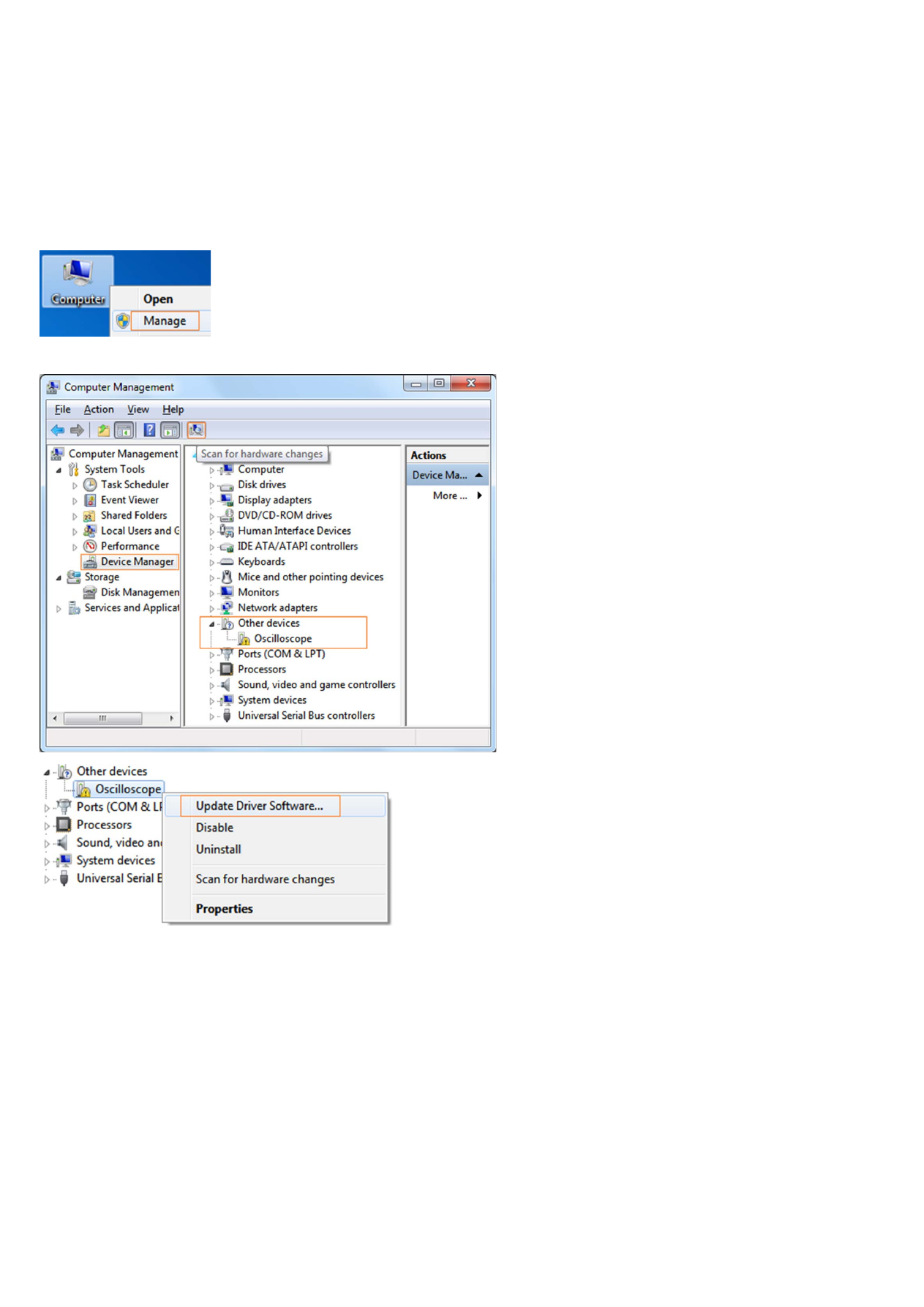
Right click [Computer], you can find it on the desktop, or in [Start] menu.
in the pop up menu, click [Manage] and it will open a window named «Computer Management», as follow, in the left side click [Device Manager], it will show a devices tree in
the middle, and then click the last one button «Scan for hardware changes» in tool bar as follow, and if the device is running well and plugged into PC, computer will detect an
unknown device with a «!» icon.
Right click the unknown device icon, in the pop up menu click [Update Driver Software…],
In the open window, select [Browse my computer for driver software],
3
Изображения служат только для ознакомления,
см. техническую документацию
Добавить в корзину 1 шт.
на сумму 8 360 руб.
Номенклатурный номер: 9000887301
Артикул: VDS1022
Бренд / Производитель: Owon

Описание
Количество каналов: два + канал внешней синхронизации
Полоса пропускания: 25 МГц
Частота дискретизации в реальном времени:
одноканальный режим — 0,5 Гц … 100 МГц
двухканальный режим — 0,5 Гц … 100 МГц на канал
Горизонтальная развертки: 5 нс/дел … 100 с/дел
Типовое время нарастания: ≤14 нс
Тип развертки: авто, ждущий, однократный
Вертикальная развертка: 5 мВ/дел … 5 В/дел, разрешение: 8 бит
Синхронизация:
по фронту, по видеосигналу (PAL, SECAM, NTSC- поле/строка), по скорости нарастания, по длительности импульса, поочередная
Автоматическая установка оптимального режима развертки и синхронизации
Автоматические измерения: 20 параметров
Курсорные измерения: (∆V, ∆t)
Сравнение сигнала с предварительно заданной маской
Математические функции: сложение, вычитание, умножение, деление, БПФ
Глубина памяти: 5K
Встроенный частотомер: 6-ти разрядный, от 2 Гц до 25 МГц
Максимальное входное напряжение: 40 В размах (постоянная + переменная составляющая)
Входной импеданс: 1 МОм ±2%, 10 пФ ±5 пФ
Русскоязычное программное обеспечение для ОС: Windows XP/Vista/7/8 (32/64 бит)
Интерфейс передачи данных: USB1.1 без дополнительного питания
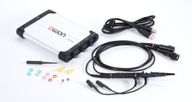
Комплект поставки:
USB осциллограф — 1 шт.
пассивный щуп 1:1 (1:10) — 2 шт.
кабель USB — 1 шт.
CD с программным обеспечением — 1 шт.
инструкция по эксплуатации — 1 шт.
Размеры: 170 х 120 х 18 мм
Масса: 260 г
Масса с упаковкой: 650 г
Технические параметры
Техническая документация
Сроки доставки
Доставка в регион Курск
| Магазин «ЧИП и ДИП» | 22 сентября1 | бесплатно |
| Курьер | 25 сентября1 | 496 руб.2 |
| ПВЗ 5Post | 22 сентября1 | 99 руб.2 |
| ПВЗ Яндекс Доставка | 22 сентября1 | 99 руб.2 |
| ПВЗ Boxberry | 22 сентября1 | 283 руб.3 |
| ПВЗ Л-Пост | 22 сентября1 | 484 руб.3 |
| ПВЗ СДЭК | 25 сентября1 | 351 руб.3 |
| ТК DPD | 20 сентября1 | 674 руб.2 |
| ТК «Деловые линии» | 21 сентября1 | 843 руб.2 |
| Почта России | 29 сентября1 | 286 руб.2 |
Цена и наличие в магазинах
| Курск, ул. Карла Маркса, 68, ТЦ «Мега Гринн», 1 этаж |
нет в наличии |
Розничная цена: 8 360 руб.
Перед вами файл pdf, где представлена инструкция (руководство) на русском для OWON VDS1022. Вы можете скачать ее либо изучить в онлайн режиме.
Подробные сведения об инструкции:
Устройство из раздела: цифровой USB осциллограф
Бренд-производитель: OWON
Наименование модели: OWON VDS1022
Язык: Руководство на русском языке
Файл: pdf
Размер файла: 3,58 MB

Скачать инструкцию к HARPER HDT2-1110
ЗАГРУЗИТЬ
Просмотр инструкции онлайн
Вы здесь: Главная / Технические материалы / Руководство пользователя
OWON 35-Series & B41T (+) Мультиметр БЫСТРОЕ РУКОВОДСТВО ЗАГРУЗИТЬ
OWON Near Field Probe Set Instruction_Manual СКАЧАТЬ
OWON DSO SDS-E Series БЫСТРОЕ РУКОВОДСТВО ЗАГРУЗИТЬ
Руководство пользователя SDS-E Series DSO СКАЧАТЬ
XDS3000-E Series 4 CH DSO инструкция по эксплуатации СКАЧАТЬ БЕСПЛАТНО
XDS3000-E Series 4CH DSO БЫСТРОЕ РУКОВОДСТВО ЗАГРУЗИТЬ
XSA1000 Series Spectrum Analyzer инструкция по эксплуатации СКАЧАТЬ БЕСПЛАТНО
XSA1000 Series Spectrum Analyzer пользователь Краткое руководство ЗАГРУЗКА
ODP3031 программируемый источник питания постоянного тока руководство пользователя СКАЧАТЬ
ODP 3032 программируемый источник питания постоянного тока руководство пользователя ЗАГРУЗКА
Сетевой источник питания с тройным выходом ODP РУКОВОДСТВО ПО ЭКСПЛУАТАЦИИ ЗАГРУЗИТЬ
OWON CM240 Digital Clamp Meter USER_MANUAL ЗАГРУЗКА
OWON 35 и 41 Series DMM Руководство пользователя ЗАГРУЗКА
OWON 33 Series DMM Руководство пользователя ЗАГРУЗКА
Руководство пользователя 1-канального DSO серии HDS СКАЧАТЬ
Руководство пользователя DSS серии HDS-N СКАЧАТЬ
MSO Series DSO инструкция по эксплуатации СКАЧАТЬ
SDS1000 Series DSO инструкция по эксплуатации СКАЧАТЬ
XDS Series n-in-1 DSO quick guide СКАЧАТЬ
AG-S серия {5 / 10MHz} произвольная генератор формы сигнала скоростная СКАЧАТЬ
AG-S серия {5 / 10MHz} произвольный генератор формы сигнала Руководство пользователя СКАЧАТЬ
Руководство пользователя цифрового мультиметра серии XDM СКАЧАТЬ
XDS Series n-in-1 DSO инструкция по эксплуатации СКАЧАТЬ
CM240 Digital Clamp Meter руководство пользователя СКАЧАТЬ
Руководство пользователя цифрового мультиметра серии DM СКАЧАТЬ
Руководство пользователя TDS Series DSO СКАЧАТЬ
Руководство пользователя SDS DSO DOWNLOAD
Генератор произвольной формы сигналов серии AG-S. СКАЧАТЬ
AG1022 / AG1012 произвольный генератор формы сигнала Руководство пользователя СКАЧАТЬ
AG (-F) Серия генераторов произвольных генераторов сигналов СКАЧАТЬ
Руководство пользователя HDS Series DSO СКАЧАТЬ
HDS1021M DSO инструкция по эксплуатации ЗАГРУЗИТЬ
Руководство пользователя SDS-E DSO (за исключением SDS5032E) СКАЧАТЬ
SDS5032E DSO инструкция по эксплуатации ЗАГРУЗИТЬ
Руководство пользователя осциллографа серии VDS серии DOWNLOAD
VDS2064 / L / VDS3104 / L «help» document СКАЧАТЬ
VDS2062 / L / VDS3102 / L «help» document СКАЧАТЬ
VDS1022 / I / VDS2052 «help» document СКАЧАТЬ
Wave Rambler Pen-type PC осциллограф «help» document СКАЧАТЬ