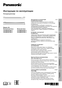
Инструкция по эксплуатации кондиционера Panasonic R410A с системой VRF

Модели R410A
Модель №.

Прежде чем приступить к установке, прочтите Инструкции по установке.
В частности, вам нужно будет прочитать в разделе «ВАЖНО!» раздел вверху страницы.
ВАЖНЫЙ! Прочтите, прежде чем начать
Этот кондиционер должен быть установлен местным торговым дилером или установщиком. Эта информация предоставляется для использования только уполномоченными лицами. Для обеспечения безопасной установки и безотказной работы необходимо:
Внимательно прочтите эту брошюру с инструкциями перед началом работы.
- Точно следуйте инструкциям по установке или ремонту каждого элемента.
- Этот кондиционер должен быть установлен в соответствии с национальными правилами электропроводки.
- Внимательно прочтите все предупреждения и предостережения в данном руководстве.
![]() ПРЕДУПРЕЖДЕНИЕ
ПРЕДУПРЕЖДЕНИЕ
Этот символ используется для обозначения опасных или небезопасных действий, которые могут привести к серьезной травме или смерти. Этот символ используется для обозначения опасных или небезопасных действий, которые могут привести к травмам или повреждению имущества.
При необходимости обратитесь за помощью Эти инструкции содержат всю информацию, необходимую для большинства условий установки. Если вам нужна помощь в решении конкретной проблемы, обратитесь за дополнительными инструкциями в свой центр продаж/обслуживания или к сертифицированному дилеру.
В случае неправильной установки, Производитель никоим образом не несет ответственности за неправильную установку или техническое обслуживание, в том числе за несоблюдение инструкций, содержащихся в этом документе.
ОСОБЫЕ МЕРЫ ПРЕДОСТОРОЖНОСТИ
ПРЕДУПРЕЖДЕНИЕ Во время проводки
 ПОРАЖЕНИЕ ЭЛЕКТРИЧЕСКИМ ТОКОМ МОЖЕТ ПРИВЕСТИ К СЕРЬЕЗНЫМ ТРАВМАМ ИЛИ СМЕРТИ.
ЭТА СИСТЕМА ДОЛЖНА БЫТЬ ПОДКЛЮЧЕНА ТОЛЬКО КВАЛИФИЦИРОВАННЫМ И ОПЫТНЫМ ЭЛЕКТРИКОМ.
- Не подавайте питание на устройство, пока вся проводка и трубопроводы не будут полностью подсоединены и проверены.
- В этой системе используется очень опасный электрический ток.tagе. При подключении внимательно следуйте схеме подключения и данным инструкциям. Неправильное подключение и плохое заземление могут привести к случайным травмам или смерти.
- Надежно подключите всю проводку. Ненадежное соединение проводки может привести к перегреву в местах соединения и возможному возгоранию.
- Следите за тем, чтобы для каждого блока использовалась отдельная розетка.
- Следить за тем, чтобы для каждого блока использовалась отдельная розетка, а в стационарную электропроводку было встроено устройство полного отключения с разделением контактов на всех полюсах в соответствии с правилами электромонтажа.
- Для предотвращения возможных опасных ситуаций при нарушении изоляции агрегат необходимо заземлить.
Во время транспортировки
Будьте осторожны при подъеме и перемещении внутреннего и наружного блоков. Найдите помощника и согните ноги в коленях, чтобы уменьшить нагрузку на спину. Об острые края или тонкие алюминиевые ребра кондиционера можно порезать пальцы.
Во время установки…
Выберите прочное и достаточно прочное место для установки, чтобы поддерживать или удерживать устройство, а затем выберите место, удобное для обслуживания. …В помещении Надлежащим образом изолируйте все трубопроводы внутри помещения, чтобы предотвратить «запотевание», которое может вызвать капание воды и повреждение стен и пола водой. Пожарная сигнализация и выходы воздуховодов должны находиться на расстоянии не менее 1.5 м от агрегата. …В дamp или неустойчивые места Используйте высокие опорные плиты или бетонные блоки, чтобы обеспечить прочное ровное основание для наружного блока. Это предотвратит попадание воды или ненормальную вибрацию. …В местах с сильным ветром Закрепите наружный блок при сильном ветре Надежно закрепите наружный блок с помощью болтов и металлического каркаса. Установите подходящее ветровое стекло. …В снежных регионах (для систем с тепловым насосом) Установите наружный блок на высокой платформе над уровнем сугроба. Установите вентиляторы с защитой от снега. …В прачечных Не устанавливайте в прачечных. Внутренний блок не защищен от капель.
При подсоединении трубопровода хладагента
![]() ПРЕДУПРЕЖДЕНИЕ
ПРЕДУПРЕЖДЕНИЕ
- Во время работ с трубопроводом не допускайте попадания воздуха, отличного от указанного хладагента (R410A), в цикл охлаждения. Это приводит к уменьшению объема и риску взрыва и травм из-за высокого объема.tagе в холодильном цикле.
- Утечка газообразного хладагента может привести к пожару.
- Не добавляйте и не заменяйте хладагент другого типа, кроме указанного. Это может привести к повреждению изделия, разрыву, травме и т. д.
- В случае утечки хладагента во время установки хорошо проветрите помещение. Будьте осторожны, чтобы не допустить контакта газообразного хладагента с огнем, так как при этом образуется ядовитый газ.
- Длина трубопровода должна быть как можно короче.
- Используйте раструб при соединении трубопровода. Нанесите охлаждающую смазку на контактные поверхности соединяемых труб перед их соединением, затем затяните гайку динамометрическим ключом, чтобы обеспечить герметичность соединения.
- Перед пробным пуском тщательно проверьте соединения на герметичность. Избегайте утечки хладагента при монтаже или перемонтаже трубопроводов, а также при ремонте компонентов системы охлаждения. Обращайтесь с жидким хладагентом с осторожностью, так как это может привести к обморожению.
Во время службы
- Отключите питание на главном распределительном щите (линии электропередач) перед открытием установки для проверки или ремонта электрических частей и проводки. Держите пальцы и одежду подальше от движущихся частей.
- Очистите территорию после окончания работ, не забывая проверить, чтобы внутри обслуживаемого агрегата не осталась металлическая стружка или куски проводки.
![]() ПРЕДУПРЕЖДЕНИЕ
ПРЕДУПРЕЖДЕНИЕ
- Ни при каких обстоятельствах не разбирайте и не модифицируйте этот продукт. Модифицированное или разобранное устройство может привести к возгоранию, поражению электрическим током или травмам.
- Не позволяйте пользователям выполнять уборку внутри внутреннего и наружного блоков. Обратитесь к авторизованному дилеру или очистителю.
- В случае неисправности устройства не ремонтируйте его самостоятельно. Свяжитесь с местным продавцом или сервисным дилером для ремонта.
- Не прикасайтесь к воздухозаборнику или острым алюминиевым ребрам наружного блока. Это может привести к травме.
- Проветривайте закрытые помещения при установке или проверке системы охлаждения. Выделившийся газообразный хладагент может образовать опасный токсичный газ при контакте с огнем или высокими температурами.
- После установки убедитесь в отсутствии утечки хладагента. Контакт газа с горящей плитой, газовым водонагревателем, электронагревателем или другим источником тепла может привести к образованию токсичного газа.
Другое

ИЗВЕЩЕНИЕ
Английский текст является оригинальной инструкцией. Текст на других языках является переводом оригинальной инструкции.
ВАЖНАЯ ИНФОРМАЦИЯ ОБ ИСПОЛЬЗОВАНИИ ХЛАДАГЕНТА
Этот продукт содержит фторсодержащие парниковые газы, подпадающие под действие Киотского протокола. Не выпускайте газы в атмосферу.
Тип хладагента: R410A
Значение ПГП(1): 1975
(1)GWP = потенциал глобального потепления
Периодические проверки на наличие утечек хладагента могут регулироваться в зависимости от европейского или местного законодательства. Для получения дополнительной информации обратитесь к местному дилеру.
Ярлык бывшийample: Тип наружного блока
Используйте несмываемые чернила для заполнения, ÿ 1 заправки хладагента на заводе-изготовителе ÿ 2 дополнительных заправок хладагента на месте и ÿ 1 + 2 полной заправки хладагента на этикетке заправки хладагента, поставляемой с изделием.
Заполненная этикетка должна быть размещена рядом с погрузочным портом (например,ample, на внутренней стороне сервисной крышки).

- Заводская заправка изделия хладагентом: см. заводскую табличку агрегата: см. паспортную табличку агрегата гребенка хладагента и заправки
1. ОБЩИЕ ПОЛОЖЕНИЯ
1. ОБЩИЕ СВЕДЕНИЯ В этой брошюре кратко описывается способ установки и местонахождение системы кондиционирования воздуха. Перед эксплуатацией полностью прочтите весь комплект инструкций для внутреннего и наружного блоков и убедитесь, что все перечисленные аксессуары входят в комплект поставки системы.
1-1. Инструменты, необходимые для установки (не входят в комплект)
- Плоская отвертка
- Крестовая отвертка
- Нож или инструмент для зачистки проводов
- Рулетка
- Уровень с отвесом
- Ножовка или кольцевая пила
- Кольцевая пила
- Отверстие дрель
- Молот
- Сверлить
- Труборез
- Инструмент для развальцовки труб
- Гаечный ключ
- Разводной ключ
- Развертка (удаление заусенцев)
1-2. Аксессуары, поставляемые с устройством
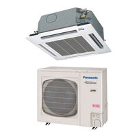
4-сторонняя кассета 60 × 60 (тип Y2)

- Используйте винты M10 в качестве подвесных болтов. Поставка на месте подвесных болтов и
1-3. Тип медной трубы и изоляционный материал Если вы хотите приобрести эти материалы отдельно на месте, вам потребуются:
- Раскисленная отожженная медная труба для трубопровода хладагента.
- Изоляция из пенополиэтилена для медных труб ровно по длине трубопровода. Толщина утеплителя должна быть не менее 8 мм. 3. Используйте изолированный медный провод для полевой проводки. Размер провода зависит от общей длины провода. Подробную информацию см. в пункте 4. ЭЛЕКТРИЧЕСКАЯ ПРОВОДКА.
![]() ПРЕДУПРЕЖДЕНИЕ
ПРЕДУПРЕЖДЕНИЕ
Пожалуйста, ознакомьтесь с вашими местными нормами по эксплуатации и техническому обслуживанию электроустановок перед покупкой провода. См. также любые дополнительные инструкции или упомянутые ограничения.
1-4. Дополнительные материалы, необходимые для установки 1.
Лента для систем охлаждения (армированная) 2. Изолированные клипсы или кл.amps для проводных соединений (см. местные правила)
3. Шпаклевка
4. Смазка для трубопроводов хладагента
5. Зажимы или клamps для защиты трубопровода хладагента
6. Весы
2. ВЫБОР МЕСТА УСТАНОВКИ
2-1. внутренний блок
ИЗБЕГАТЬ:
- Места, где возможна утечка горючего газа.
- Места с повышенным содержанием масляного тумана.
- воздействие прямых солнечных лучей.
- Места рядом с источниками тепла, которые могут повлиять на работу устройства.
- Места, где наружный воздух может напрямую попадать в помещение. Это может вызвать «конденсацию» на выходных отверстиях для воздуха, в результате чего вода будет разбрызгиваться или капать из них.
- Места, где пульт дистанционного управления может быть забрызган водой или намок.
- Установка пульта за шторами или мебелью.
- Места, где генерируется высокочастотное излучение.
DO:
- выбор подходящего положения, из которого равномерно охлаждается каждый из углов комнаты.
- выбор положения, при котором потолок достаточно прочен, чтобы выдержать вес блока.
![]() ПРЕДУПРЕЖДЕНИЕ
ПРЕДУПРЕЖДЕНИЕ
Место установки должно быть достаточно прочным, чтобы выдержать четырехкратный вес внутреннего блока.
- выбор положения, при котором длина трубопровода до наружного блока и сливной трубы будет минимальной.
- Обеспечьте пространство для эксплуатации и обслуживания, а также беспрепятственный поток воздуха вокруг устройства.
- Установите блок в пределах максимального перепада высот от наружного блока и в пределах общей длины трубопровода (L) от наружного блока, как указано в руководстве по установке, прилагаемом к наружному блоку.
- предусмотреть место для установки пульта дистанционного управления на высоте около 1 м от пола в месте, где нет прямых солнечных лучей или потока холодного воздуха от внутреннего блока.
ЗАМЕТКА
Если расстояние от пола до потолка больше 3 м, циркуляция воздуха уменьшится.

* Если высота от пола до потолка превышает три метра, ухудшается распределение воздушного потока и снижается эффект.
3. ПРОЦЕДУРА УСТАНОВКИ ВНУТРЕННЕГО БЛОКА
3-1. Подготовка к подвешиванию к потолку В данном устройстве используется дренажный насос. С помощью спиртового уровня проверьте горизонтальность установки устройства.
3-2. Размеры потолочных отверстий и расположение подвесных болтов В этом кондиционере используется сливной привод. Установите блок горизонтально, используя уровень.
Установочная бумажная модель расширяется или сжимается в зависимости от температуры и влажности. Перед использованием проверьте размеры.
![]() ПРЕДУПРЕЖДЕНИЕ
ПРЕДУПРЕЖДЕНИЕ
Во время установки соблюдайте осторожность, чтобы не повредить электрические провода.
- Размеры бумажной модели для установки такие же, как и размеры проемов на потолке.
- Обязательно обсудите работу по сверлению потолка с соответствующими работниками.

3-3. Расположение корпуса кондиционера и потолочной поверхности


![]() ПРЕДУПРЕЖДЕНИЕ
ПРЕДУПРЕЖДЕНИЕ
Затяните гайку и болт, чтобы предотвратить падение устройства.
3-4. Установка дренажной трубы

ЗАМЕТКА
Убедитесь, что дренажная труба установлена с уклоном вниз (1/100 или более) и что в ней нет водосборников.
3-5. Дренажный трубопровод внутреннего блока • При подсоединении дренажного трубопровода не прилагайте чрезмерных усилий к дренажному отверстию на внутреннем блоке. • Внешний диаметр дренажного соединения внутреннего блока составляет 32 мм. Материал трубопровода: трубы ПВХ ВП-25 и фитинги.
- Обязательно изолируйте дренажный трубопровод. Теплоизоляционный материал:
Вспененный полиэтилен толщиной более 8 мм (местная поставка). - Дренажный трубопровод должен иметь уклон (от 1/50 до 1/100); избегайте наклона и подъема, чтобы избежать обратного потока.
- Убедитесь, что в сливном шланге нет воздушной пробки, чтобы обеспечить плавный поток воды и отсутствие посторонних звуков.


Проверка слива
В этом кондиционере используется сливной привод для слива воды. Следуйте описанной ниже процедуре, чтобы проверить работу сливного привода. • Подсоедините основную сливную трубу
к внешней стороне стены и временно оставьте ее до завершения теста.
- Подайте воду в регулируемый сливной шланг и проверьте трубопровод на наличие утечек.
- После завершения электропроводки обязательно проверьте сливной привод на нормальную работу и отсутствие шумов.

4. ЭЛЕКТРИЧЕСКАЯ ПРОВОДКА
4-1. Основные меры предосторожности при подключении
- Перед подключением проверьте номинальный объемtage блока, указанного на его паспортной табличке, а затем подключите его в точном соответствии со схемой подключения.
- Предусмотреть, чтобы для каждого блока использовалась отдельная розетка и автоматический выключатель. (3)
- Устройство должно быть заземлено, чтобы предотвратить потенциальную опасность в случае повреждения изоляции.
- Каждое подключение электропроводки должно быть выполнено в соответствии со схемой электропроводки системы. Неправильная проводка может привести к неисправности или повреждению устройства.
- Не допускайте контакта электропроводки с трубопроводом хладагента, компрессором или любыми другими движущимися частями вентилятора.
- Несанкционированные изменения внутренней проводки могут быть очень опасны. Производитель не несет ответственности за любые повреждения или неисправности, возникшие в результате несанкционированных модификаций. (7) Спецификации диаметра проводки различаются в зависимости от региона. Для получения информации о местных правилах электромонтажа перед началом работ обратитесь к МЕСТНЫМ НОРМАМ ЭЛЕКТРОЭНЕРГИИ. Необходимо убедиться, что установка соответствует всем применимым нормам и правилам.
- Во избежание неисправности кондиционера, вызванной электрическими помехами, при подключении необходимо соблюдать следующие меры предосторожности: Проводку пульта дистанционного управления и проводку управления между блоками следует прокладывать отдельно от силовой проводки между блоками. Используйте экранированные провода для соединения проводки управления и заземляйте оплетку с обеих сторон.
- Если шнур питания поврежден, его необходимо заменить в сервисном центре, указанном производителем, так как для этого требуются специальные инструменты.
4-2. Рекомендуемая длина и диаметр провода для энергосистемы


*1 Эта максимальная длина представляет собойtage в 2% *2 С кольцевым креплением clamp
4-3. Схемы подключения системы

Рис. 4-1
ЗАМЕТКА
- См. раздел «Рекомендуемая длина и диаметр проводки для системы электропитания» для объяснения размеров «B», «C», «D», «E» и «F» на приведенной выше схеме. Пожалуйста, обратитесь к руководству по установке наружного блока для объяснения размера «A».
- На схеме подключения внутреннего блока показаны клеммные колодки, но клеммные колодки вашего оборудования могут отличаться от этой схемы.
- Перед включением питания необходимо установить адрес контура хладагента (RC).
- Для установки адреса пульта дистанционного управления см. инструкции по установке, прилагаемые к наружному блоку. Настройка адреса может выполняться автоматически с пульта дистанционного управления.
![]() ПРЕДУПРЕЖДЕНИЕ
ПРЕДУПРЕЖДЕНИЕ
![]() Это оборудование должно быть надежно заземлено
Это оборудование должно быть надежно заземлено

![]() ПРЕДУПРЕЖДЕНИЕ
ПРЕДУПРЕЖДЕНИЕ
(1) При объединении наружных блоков в сеть отсоедините удлинительную клемму от закорачивающей вилки и от всех наружных блоков, кроме любого из наружных блоков. (Во время отгрузки: в состоянии короткого замыкания.) Не снимайте заглушку в случае неподключенной системы (отсутствует соединительная проводка между наружными блоками).
(2) Не прокладывайте проводку управления между блоками в виде петли. (Рисунок 4-3)


(6) Используйте стандартные европейские шнуры питания (например, H05RN-F или H07RN-F, соответствующие
рейтинг CENELEC (HAR)), или используйте кабели, соответствующие стандарту IEC. (60245 IEC57, 60245 IEC66) Соединительный кабель между внутренним и наружным блоками должен представлять собой 5- или 3-жильный гибкий шнур с полихлоропреновой оболочкой * 1.5 мм2. Обозначение типа Шнур питания 60245 IEC 57 (H05RN-F, GP85PCP и т. д.) или выше.
Процедура подключения терминала


Соединение проводки бывш.ampле

5. ТРУБОПРОВОДНЫЕ РАБОТЫ
Жидкостный трубопровод соединяется с накидной гайкой, а газопровод соединяется с помощью пайки.
5-1. Соединение трубопровода хладагента
Используйте раструб Многие обычные сплит-кондиционеры используют раструб для соединения труб хладагента между внутренним и наружным блоками. При этом методе соединения медные трубы развальцовываются на каждом конце и соединяются с помощью накидных гаек.
Процедура развальцовки с помощью развальцовочного инструмента
(1) Отрежьте медную трубу до нужной длины труборезом. Рекомендуется отрезать ок. на 30 – 50 см длиннее желаемой длины трубопровода. (2) Снимите заусенцы с каждого конца медного трубопровода с помощью развертки или file. Этот процесс очень важен и должен выполняться осторожно, чтобы получить хорошее коническое соединение. Следите за тем, чтобы в трубопровод не попали примеси (влага, грязь, металлическая стружка и т.п.). (Рис. 5-1 и 5-2)

ЗАМЕТКА
Во время развертывания держите конец трубы вниз и следите за тем, чтобы в трубу не попала медная стружка. (Рис. 5-2) (3) Отвинтите накидную гайку от блока и установите ее на медную трубу.
(4) Сделайте коническое соединение на концах медных труб с помощью развальцовки. (Рисунок 5-3)

ЗАМЕТКА
Хорошее коническое соединение должно иметь следующие характеристики: внутренняя поверхность должна быть блестящей и гладкой края должны быть гладкими скошенные стороны должны быть одинаковой длины
Меры предосторожности перед окончательным соединением труб
(1) Установите герметичный колпачок или наклейте водонепроницаемую ленту, чтобы предотвратить попадание пыли или воды в трубы перед использованием.
(2) Обязательно нанесите охлаждающую смазку (эфирное масло) на внутреннюю часть накидной гайки перед подсоединением трубопровода. Это уменьшит утечки газа. (Рисунок 5-4)

(3) Чтобы выполнить правильное соединение, поместите раструбную трубу и коническую трубу прямо напротив друг друга, затем плотно затяните накидную гайку, чтобы добиться точного совпадения. (Рисунок 5-5)

• Откорректируйте форму жидкостной трубы с помощью трубогиба на месте установки и соедините ее с клапаном трубопровода на стороне жидкости конусным соединением.
Меры предосторожности во время пайки
- Замените воздух внутри трубы газообразным азотом, чтобы предотвратить образование пленки оксида меди во время процесса пайки. (Использование кислорода, углекислого газа и фреона недопустимо.)
- Не допускайте слишком сильного повышения температуры трубопровода во время пайки. Газообразный азот внутри трубопровода может перегреться, что приведет к повреждению клапанов в системе охлаждения. Поэтому дайте трубе остыть во время пайки.
- Используйте редукционный клапан для баллона с азотом.
- Не используйте антиоксиданты. Эти продукты могут неблагоприятно воздействовать на хладагент и охлаждающее масло и вызывать повреждения или неисправности.
5-2. Соединительный трубопровод между внутренним и наружным блоками (1) Надежно соедините трубопровод хладагента изнутри, выходящий из стены, с трубопроводом снаружи.
Соединение трубопровода внутреннего блока ( 1, 2… n-1)

(2) Используйте указанный момент затяжки для закрепления накидных гаек. •
При снятии накидных гаек с соединений трубопроводов или при их затягивании после соединения трубопроводов обязательно используйте 2 разводных ключа или гаечные ключи с открытым зевом. (Рисунок 5-6)
Если развальцовочные гайки перетянуты, развальцовочное соединение может
быть повреждены, что может привести к утечке хладагента и стать причиной травм или удушья пассажиров.

- Что касается накидных гаек на соединительных трубопроводах, обязательно используйте накидные гайки, поставляемые с агрегатом, или накидные гайки для хладагента R410A (тип 2). Используемый трубопровод хладагента должен иметь соответствующую толщину стенки, как показано в таблице ниже.

Поскольку давление примерно в 1.6 раза превышает нормальное давление хладагента, использование обычных накидных гаек (тип 1) или тонкостенных труб может привести к разрыву трубы, что может привести к травме или удушью из-за утечки хладагента.
- Чтобы предотвратить повреждение конусного соединения, вызванное чрезмерной затяжкой накидных гаек, используйте приведенную выше таблицу в качестве руководства при затягивании. приведенной выше таблице в качестве ориентира при затяжке.
- При затягивании накидной гайки на жидкостной трубе используйте разводной ключ с номинальной длиной рукоятки 200 мм.
5-3. Изоляция трубопроводов хладагента Изоляция трубопроводов
Теплоизоляция должна применяться ко всем трубопроводам агрегата, включая распределительное соединение (местная поставка). * В случае газопровода изоляционный материал должен быть термостойким до 120°C и выше. В случае других трубопроводов он должен быть термостойким до 80°С и более. Толщина изоляционного материала должна быть 10 мм и более.
Если температура внутри потолка превышает 30°C по сухому термометру, а относительная влажность превышает 70%, увеличьте толщину изоляционного материала газопровода на 1 позицию.

![]() ПРЕДУПРЕЖДЕНИЕ
ПРЕДУПРЕЖДЕНИЕ
Если квадратный воздуховод установлен снаружи наружного блока, убедитесь, что имеется достаточно свободного места для доступа к вентиляционным отверстиям, а также для установки и снятия панелей.
Оберните раструбные гайки Оберните
белая лента вокруг накидных гаек на соединениях газовых труб. Затем накройте соединения трубопровода изоляцией с развальцовкой и заклейте зазор в месте раструба прилагаемой черной изоляционной лентой. Наконец, закрепите изоляцию с обоих концов с помощью прилагаемого винилового клея.ampс. (Рисунок 5-8) теплоизоляция.
![]() ПРЕДУПРЕЖДЕНИЕ
ПРЕДУПРЕЖДЕНИЕ
Обязательно изолируйте дренажные, жидкостные и газовые трубопроводы. Недостаточная теплоизоляция приведет к протечке воды.
(1) Используйте теплоизоляционный материал для трубопроводов охлаждения, которые обладают высокой термостойкостью (более 120°C).

(2) Меры предосторожности при высокой влажности.
Этот кондиционер был протестирован в соответствии с требованиями «Стандартных условий тумана JIS», и никаких неисправностей не было подтверждено. Однако при длительной работе в условиях высокой влажности (температура конденсации: более 23°C) могут образовываться капли воды. В таком случае добавьте теплоизоляционный материал в соответствии с приведенной ниже процедурой: Подготовка теплоизоляционного материала…
Адиабатическая стекловата толщиной от 10 до 20 мм.
- Прикрепите стекловату ко всем кондиционерам, которые расположены в потолочной атмосфере.
- В дополнение к обычной теплоизоляции (толщина: более 8 мм) для трубопровода хладагента (газопровод: толстый трубопровод) и дренажного трубопровода добавьте дополнительный материал толщиной от 10 до 30 мм.
Герметизация стен
Если наружный блок установлен выше внутреннего блока, установите сифон для предотвращения попадания дождевой воды на стену при транспортировке по трубопроводу.
- Пространство между трубопроводом, проводкой и сливным шлангом заполнить замазкой, а отверстие в стене заделать. Убедитесь, что дождевая вода не просачивается в стену.

5-4. Обмотка труб лентой (1)
На этом сtagд., трубы хладагента (и электропроводка, если это разрешено местными нормами) должны быть обмотаны армированной лентой в 1 пучок.
Чтобы конденсат не переливался через края дренажного поддона, прокладывайте дренажный шланг отдельно от трубопровода хладагента. (2) Намотайте армирующую ленту от нижней части внешнего блока до верхней части трубопровода, где он входит в стену. При обматывании трубопровода перекрывайте половину каждого предыдущего витка ленты.
(3) Прикрепите пучок труб к стене с помощью 1 кл.amp каждый ок. каждый метр. (Рисунок 5-10)

ЗАМЕТКА
Не наматывайте бронеленту слишком туго, так как это снизит эффективность теплоизоляции. Также убедитесь, что шланг для слива конденсата отделен от пучка и что конденсат стекает с агрегата и трубопровода.
5-5. Завершение установки После завершая утепление и обмотку трубопровода, используйте герметизирующую замазку, чтобы заделать отверстие в стене, чтобы предотвратить попадание дождя и сквозняков. (Рисунок 5-11)

6. ПРОЦЕДУРА УСТАНОВКИ ПУЛЬТА ТАЙМЕРА
(НЕОБЯЗАТЕЛЬНАЯ ЧАСТЬ)
ЗАМЕТКА
См. инструкции по эксплуатации, прилагаемые к дополнительному пульту дистанционного управления с таймером.
7. УСТАНОВКА ДЕКОРАТИВНОЙ ПАНЕЛИ
При использовании беспроводного пульта дистанционного управления выполните шаги 7-3 «При использовании беспроводного пульта дистанционного управления вместо проводного» перед установкой декоративной панели.
7-1. Перед установкой декоративной панели (1) Снимите решетку воздухозаборника и воздушный фильтр с декоративной панели. а) Открутите 2 винта на защелке решетки входа воздуха. (Рис. 7-1) (После установки декоративной панели установите на место решетку воздухозаборника.)

7-2. Установка декоративной панели Декоративная панель имеет направление установки. Подтвердите направление, отобразив сторону трубопровода. (1) Снимите решетку воздухозаборника, сдвинув зажимы к центру.

- Наденьте петлю на отверстие декоративной панели. (Любое направление установки.) (2) Крепление декоративной панели.
- Перед установкой декоративной панели временно затяните крепежные винты (3 шт.). (Для временной фиксации передней решетки.)
- Перед креплением наденьте декоративную панель на винты (3 шт.), переместите декоративную панель, как показано на рисунке, и затяните все винты (4 шт.).

![]() ПРЕДУПРЕЖДЕНИЕ
ПРЕДУПРЕЖДЕНИЕ
- Заранее проверьте высоту от потолка до устройства. Направление установки передней решетки определяется направлением установки.
- Для крепления декоративной панели используйте только винты 35 мм из комплекта поставки.
- Не используйте более длинные винты, так как они могут повредить дренажный поддон и другие детали.
(3) Выровняйте декоративную панель и потолочную стену так, чтобы между ними не было зазора. Отрегулируйте высоту внутреннего блока, если между потолочной стеной и декоративной панелью есть зазор.

(4) Откройте крышку внутреннего блока управления. (3 винта) (5) Плотно вставьте соединитель декоративных жалюзи во внутреннюю плату LM и WL. Будьте осторожны, чтобы не зажать шнур между блоком управления и крышкой блока управления. (6) Выполнив описанные выше действия, установите снятую деталь, выполнив действия по снятию в обратном порядке.

![]() ПРЕДУПРЕЖДЕНИЕ
ПРЕДУПРЕЖДЕНИЕ
Обязательно зацепите трос решетки воздухозаборника, чтобы предотвратить падение решетки и травму.

7-3. При использовании беспроводного контроллера Пульт дистанционного управления Move вместо проводного пульта дистанционного управления
При использовании беспроводного пульта дистанционного управления переместите переключатель (SW502) на плате управления внутреннего блока в положение ON.
- Невыполнение этого требования приведет к тревоге.
(Индикатор работы на дисплее будет мигать.)

8. ПОРЯДОК УСТАНОВКИ БЕСПРОВОДНОГО ПРИЕМНИКА ПУЛЬТА ДИСТАНЦИОННОГО УПРАВЛЕНИЯ
ЗАМЕТКА
См. инструкции по эксплуатации, прилагаемые к дополнительному беспроводному приемнику дистанционного управления.
9. ПРИЛОЖЕНИЕ
Уход и чистка
![]() ВНИМАНИЕ Перед очисткой отключите питание.
ВНИМАНИЕ Перед очисткой отключите питание.
ИНСТРУКЦИЯ ПО ОЧИСТКЕ
- Не используйте бензин, растворитель или чистящий порошок. Используйте только мыло (pH7) или нейтральное бытовое моющее средство.
- Не используйте воду температурой выше 40°C.
ЗАМЕТКА
- Для лучшей производительности и
Для снижения энергопотребления регулярно чистите фильтр. - Обратитесь к ближайшему дилеру за помощью в сезонной проверке.
Снимите воздушный фильтр 1 Ослабьте 2 винта с помощью отвертки Phillips. Переместите ползунок в положение ОТКРЫТО.


Решение Проблем Если кондиционер не работает должным образом, перед обращением в сервисную службу проверьте следующее. Если он по-прежнему не работает должным образом, обратитесь к своему дилеру или в сервисный центр. Внутренний блок Возможная неисправность


Наружный блок

Проверьте перед обращением в сервисную службу Возможная причина


Если кондиционер по-прежнему не работает должным образом, несмотря на вышеуказанные проверки, остановите работу и выключите выключатель питания. Затем обратитесь к местному дилеру и сообщите ему серийный номер и возможную проблему. Никогда не ремонтируйте кондиционер самостоятельно, так как это очень опасно. Также сообщите о появлении значка галочки и букв E, F, H, L, P в сочетании с цифрами на ЖК-дисплее пульта дистанционного управления.
Советы по энергосбережению Избегайте
- Не блокируйте вход и выход воздуха из устройства. Препятствия могут привести к неправильной работе устройства и возможному его повреждению.
- Не подвергайте помещение воздействию прямых солнечных лучей. Используйте навесы, жалюзи или шторы. В случае нагревания солнцем стен и потолка помещения, для его охлаждения потребуется больше времени. Полный
- Всегда держите воздушный фильтр в чистоте. (См. «Уход и чистка».) Засоренный фильтр может привести к ухудшению работы устройства.
- Держите окна, двери и любые другие отверстия закрытыми, чтобы предотвратить утечку охлажденного воздуха.
ЗАМЕТКА
В случае сбоя питания во время работы агрегата Если питание устройства временно отключено, оно возобновит работу после восстановления питания с теми же настройками, что и до сбоя питания.
Узнать больше об этом руководстве и скачать PDF:
Документы / Ресурсы
- Manuals
- Brands
- panasonic Manuals
- Air Conditioner
- R410A
Manuals and User Guides for panasonic R410A. We have 5 panasonic R410A manuals available for free PDF download: Installation Instructions Manual, Service Manual

Panasonic R410A Service Manual (231 pages)
R410A Inverter
Brand: Panasonic
|
Category: Air Conditioner
|
Size: 40.14 MB
Table of Contents
-
Technical Data
1
-
Service Manual
1
-
Please Read before Starting
2
-
When Wiring
2
-
When Installing
2
-
When Connecting Refrigerant Tubing
2
-
When Servicing
3
-
Others
3
-
Check of Density Limit
4
-
Table of Contents
5
-
Specifications
5
-
Single-Type
6
-
-
Unit Specifications
6
-
4-Way Cassette Type S-60PU1R5/U-60PE1R5
6
-
4-Way Cassette Type S-71PU1R5/U-71PE1R5
7
-
4-Way Cassette Type S-100PU1R5/U-100PE1R5
8
-
4-Way Cassette Type S-125PU1R5/U-125PE1R5
9
-
4-Way Cassette Type S-140PU1R5/U-140PE1R5
10
-
Ducted Type S-60PE1R5/U-60PE1R5
11
-
Ducted Type S-71PE1R5/U-71PE1R5
12
-
Ducted Type S-100PE1R5/U-100PE1R5
13
-
Ducted Type S-125PE1R5/U-125PE1R5
14
-
Ducted Type S-140PE1R5/U-140PE1R5
15
-
Single Split Type S-100PU1R5/U-100PE1R8
16
-
Single Split Type S-125PU1R5/U-125PE1R8
17
-
Single Split Type S-140PU1R5/U-140PE1R8
18
-
Indoor Units: S-60PU1R5/71PU1R5
19
-
-
Dimensional Data
19
-
Indoor Units: S-100PU1R5/125PU1R5/140PU1R5
20
-
Indoor Units: Ducted Type S-60PE1R5/S-71PE1R5/S-100PE1R5/S-125PE1R5/S-140PE1R5
21
-
Outdoor Units: U-60PE1R5/U-71PE1R5
22
-
Outdoor Units: U-100PE1R5/U-125PE1R5/U-140PE1R5; U-100PE1R8/U-125PE1R8/U-140PE1R8
23
-
-
Refrigerant Flow Diagram
24
-
(A) Indoor Units
24
-
(B) Outdoor Units
24
-
-
Operating Range
25
-
Heating Capacity Ratio (Maximum Capacity)
26
-
U-60PE1R5 (for 50 Hz)
26
-
Cooling Capacity Ratio (Maximum Capacity)
26
-
-
Capacity Correction Graph According to Temperature Condition
26
-
U-71PE1R5 (for 50 Hz)
27
-
U-100PE1R5 (for 50 Hz)
28
-
U-125PE1R5 (for 50 Hz)
29
-
U-140PE1R5 (for 50 Hz)
30
-
Indoor Units
31
-
4 Way Cassette Type
31
-
-
Noise Criterion Curves
31
-
Outdoor Units
33
-
Indoor Fan Performance
36
-
4-Way Cassette Type
37
-
Airflow Distance Chart
37
-
Intaking Fresh Air of 4 Way Cassette Type
39
-
Precautions Regarding External Air Intake
39
-
Flexible Cylindrical Duct
39
-
With the External Air Intake Flange Attached
40
-
External Air Intake Volume and Resistance and Operation Noise Characteristics Within the Unit
40
-
When an External Air Intake Flange (100) Is in Use
40
-
Electrical Wiring
41
-
General Precautions on Wiring
41
-
Recommended Wire Length and Wire Diameter for Power Supply System
41
-
Wiring System Diagrams
42
-
How to Connect Wiring to the Terminal
43
-
For Stranded Wiring
43
-
Examples of Shield Wires
43
-
Wiring Samples
43
-
Installation Instructions
44
-
Tubing Length
44
-
Single Type
44
-
Check of Limit Density
45
-
Minimum Indoor Volume & Fl Oor Area Relative to the Amount of Refrigerant Are Roughly as Given in the Following Table
45
-
Selecting the Location for Installation Service
46
-
Selecting the Installation Site
46
-
Select the Outdoor Unit Installation Location
46
-
Accessories Supplied with Outdoor Unit
46
-
How to Install the Outdoor Unit
48
-
Transporting
48
-
Installation
48
-
Refrigerant Installation
49
-
Precautions During Refrigerant Installation
49
-
The Local Pipes Can Protrude from any Four Directions
49
-
Precautions When Operating the 3-Way Valve for Piping Installation
50
-
Precautions for Handling the Valve Cap
50
-
Precautions for Handling the Service Ports
50
-
Precautions for Insulation Installation
50
-
Precautions for Flare Nut Installation
51
-
Vacuum Purging
51
-
Regarding Refrigerant Filling
51
-
Charging with Refrigerant
51
-
-
Electrical Wiring
52
-
Check before Test Run
54
-
Precautions Regarding Test Run
54
-
Test Run Procedure
54
-
Checks after Installation Have Completed
55
-
Regarding Delivery to the Customer
55
-
4-Way Cassette Type (U1 Type)
56
-
Electing the Installation Site (U1 Type)
56
-
How to Install the Indoor Unit
56
-
Indoor Unit
56
-
Placing the Unit Inside the Ceiling
57
-
Before Performing the Installation Drain Piping
58
-
Ceiling Surface
58
-
Installing the Drain Pipe
58
-
Checking the Drainage
60
-
How to Install the Ceiling Panel
61
-
Accessories
61
-
Preparation for Ceiling Panel Installation
61
-
Installing the Ceiling Panel
62
-
Table for DC Fan Motor Tap Setting
64
-
Stop the System before Performing These Steps
64
-
Selecting the Installation Site (E1 Type)
65
-
Selecting the Location for the Indoor Unit
66
-
Installation of Indoor Unit
66
-
Position of Suspension Bolt
66
-
Suspending the Indoor Unit
67
-
Connecting Duct to Indoor Unit
68
-
Connection for Demand and Forced Stop
69
-
Connection Procedure
69
-
When Connection to the Forced Stop Input
70
-
When Connecting the Demand Controller Input
70
-
When Connecting to the Next System Unit
71
-
Wiring Procedure
72
-
Cz-Fdu2
73
-
Filter Chamber for Indoor Unit
73
-
Optional Parts
73
-
-
Installation Instructions
73
-
Air Intake Kit for Chamber
74
-
Cz-Atu2
74
-
Air Intake Kit for Unit
75
-
Cz-Bcu2
75
-
Air Cut Insulation
76
-
Applicable Model & Use
76
-
Cz-Cfu2
76
-
List of Parts
76
-
Test Run
79
-
Electrical Data
82
-
4-Way Cassette Type S-60PU1R5/S-71PU1R5/S-100PU1R5/S-125PU1R5/S-140PU1R5
83
-
Indoor Units (Electric Wiring Diagram)
83
-
Ducted Type S-60PE1R5/S-71PE1R5/S-100PE1R5/S-125PE1R5
84
-
Ducted Type S-140PE1R5
85
-
Electric Wiring Diagram U-60PE1R5/U-71PE1R5
86
-
-
Outdoor Units (Electric Wiring Diagram)
86
-
Electric Wiring Diagram U-100PE1R5/U-125PE1R5/U-140PE1R5
87
-
Electric Wiring Diagram U-100PE1R8/U-125PE1R8/U-140PE1R8
88
-
Control Functions
90
-
Cooling Temperature Correction
91
-
Heating Temperature Correction
91
-
-
Room Temperature Control
91
-
Heating Standby
93
-
Automatic Fan Speed Control
94
-
Drain Pump Control
95
-
Automatic Heating/Cooling Control
96
-
When Setting Temperature in Remote Controller Is 20 C in the Cooling Mode
96
-
Automatic Flap Control
97
-
Filter Sign
97
-
Fan Control During Dry Mode
98
-
T10 Terminal
98
-
Ventilation Fan Output
98
-
Parameter
99
-
Cr-Pcb A746894 (U-60Pe1R5, U-71Pe1R5)
100
-
Outdoor Units Control PCB (CR-PCB, HIC-PCB)
100
-
Single-Phase Unit
100
-
Cr-Pcb A746844 (U-100Pe1R5)
101
-
Cr-Pcb A746845 (U-125Pe1R5, U-140Pe1R5)
102
-
Hic-Pcb A746895 (U-60Pe1R5, U-71Pe1R5)
103
-
Hic-Pcb A746846 (U-100Pe1R5)
104
-
Hic-Pcb A746847 (U-125Pe1R5, U-140Pe1R5)
105
-
3-Phase Unit
106
-
Cr-Pcb A746967 (U-100Pe1R8, U-125Pe1R8, U-140Pe1R8)
106
-
Hic-Pcb A746969 (U-100Pe1R8, U-125Pe1R8, U-140Pe1R8)
107
-
-
Functions of Outdoor Unit PCB
108
-
Setting the System Address (S002: Rotary Switch (Yellow), S003: 2P DIP (Black))
110
-
Self-Diagnostics Function Table
111
-
Trouble Diagnosis
114
-
Contents of Alarm Display on Remote Controller (Only Outdoor Unit)
115
-
-
Contents of Remote Controller Switch Alarm Display
115
-
Contents of LED Display on Outdoor Unit Control PCB
117
-
Outdoor Unit Control Panel LED Display
117
-
Alarms for Outdoor Units
118
-
PAC-I System Alarm Codes
118
-
Symptoms and Parts to Inspect
119
-
Check Prior to Auto Address Setting
120
-
E01 Remote Controller Reception Error
121
-
Error Detection Method
121
-
Error Diagnosis
121
-
A746802
122
-
A746803
122
-
E02 Remote Controller Transmission Error
123
-
E03 Error in Indoor Unit Receiving Signal from Remote Controller (Central)
124
-
E04 Error in Indoor Unit Receiving Signal from the Outdoor Unit
126
-
Indoor Unit Control PCB
127
-
Outdoor Unit Control
127
-
E05 Error in Indoor Unit Transmitting Signal to the Outdoor Unit
128
-
-
Setting no
128
-
E06 Outdoor Unit Failed to Receive Serial Communication Signals from Indoor Unit
129
-
E07 Outdoor Unit Sending Failure to Indoor Unit
130
-
E08 Duplicate Indoor Unit Address Settings Error
131
-
E09 more than One Remote Controller Set to Main Error
132
-
Wireless Remote Controller
132
-
E12 Automatic Address Setting Start Is Prohibited While Auto-Address Setting in Progress
133
-
E13 Error in Indoor Unit Transmitting Signal to Remote Controller
133
-
E14 Main Unit Duplication in Simultaneous-Operation Multi Control (Detected Outdoor Unit)
134
-
E15 Automatic Address Alarm (Capacity too Low)
135
-
E16 Automatic Address Alarm (Capacity too High)
136
-
E18 Faulty Communication in Group Control Wiring
137
-
E20 no Indoor Units Connected
138
-
F04 Compressor Discharge Temperature Sensor (TD) Trouble
139
-
F06 Inlet Temperature Sensor (C1) in Heat Exchanger Trouble
140
-
F07 Intermediate Temperature (C2) in Heat Exchanger Trouble
141
-
F08 Outdoor Air Temperature Sensor (TO) Trouble
142
-
F12 Compressor Inlet Suction Temperature Sensor (TS) Trouble
143
-
F31 Outdoor Unit Nonvolatile Memory (EEPROM) Trouble
144
-
H01 Primary (Input) Overcurrent Detected
145
-
H02 PAM Trouble (Single-Phase Only)
146
-
H03 Primary Current CT Sensor (Current Sensor) Failure
147
-
H05 Sensor Failure, Compressor Discharge Temperature Sensor (TD) Disconnected
148
-
H31 HIC Trouble
149
-
HIC Board IPM Pass/Fail Tests
149
-
Outdoor Unit Control HIC PCB
151
-
Outdoor Unit Control PCB
151
-
L04 Outdoor Unit Address Duplication
152
-
L10 Outdoor Unit Capacity Not Set
153
-
L13 Indoor Unit Type Setting Error
154
-
L18 4-Way Valve Operation Failure
155
-
P03 Compressor Discharge Temperature Trouble
156
-
P04 High Pressure Trouble
157
-
P05 AC Power Supply Trouble
159
-
P13 Alarm Valve Open
160
-
P14 O2 Sensor Detect
161
-
Check of Content
163
-
Meaning of Alarm
163
-
P16 Compressor Overcurrent Trouble
163
-
P22 Outdoor Unit Fan Motor Trouble
167
-
P29 Lack of INV Compressor Wiring, INV Compressor Actuation Failure (Including Locked) Due to DCCT Failure
168
-
P31 Group Control Error
169
-
Electronic Control Valve (MOV1)
171
-
-
Inspection of Parts (Outdoor Unit)
171
-
How to Detect Abnormality
172
-
Symptom: Thermostat in off Continues or Cycles off & on too Frequently
172
-
Outdoor Unit Maintenance Remote Control
174
-
Functions
175
-
Overview
175
-
System Diagram
175
-
What Is the Outdoor Unit Maintenance Remote Controller?
175
-
All Units Start/Stop
176
-
All Units Test Run
176
-
-
Normal Display Operations and Functions
176
-
Switching between Cooling/Heating
176
-
Display (Functions)
177
-
2: 7-Segment, 4-Digit Display for Remote Controller Timer Display
178
-
3: the Total Compressor Operating Time Is Displayed
178
-
-
Monitoring Operations: Display of Indoor Unit and Outdoor Unit Sensor Temperatures
179
-
Monitoring the Outdoor Unit Alarm History: Display of Outdoor Unit Alarm History
180
-
Settings Modes: Setting the Outdoor Unit EEPROM
180
-
List of Item Codes
181
-
Remote Controller Functions Section
184
-
-
Controller Display
185
-
If Group Control Is in Effect, Press the
185
-
Press and Hold the and Buttons
185
-
Press the Button
185
-
Press the Button to Return to Normal Remote
185
-
Press the Timer Time / Buttons to Select the Desired Setting Data
185
-
Simple Settings Function
185
-
Simultaneously for 4 Seconds or Longer
185
-
List of Simple Setting Items
186
-
Detailed Settings Function
187
-
List of Detailed Setting Items
188
-
Filter Sign on Times for each Model
192
-
Simple Setting Items
192
-
Detaild Setting Items
194
-
DC Fan Tap Change Procedure
197
-
List of Servicing Functions
198
-
-
Remote Controller Servicing Functions
198
-
Test Run Function
198
-
Sensor Temperature Display Function (Displayed Regardless of Whether Unit Is Operating or Stopped)
199
-
How to Install the Wireless Remote Controller Receiver
200
-
-
Warning about Installation of Receivers
201
-
Warning about Installing Remote Controls
201
-
Names and Functions
202
-
Optional Controller (Remote Controller)
202
-
Remote Controller
202
-
Wireless Remote Controller CZ-RWSU2/CZ-RWST2 /CZ-RWSL2/CZ-RWSC2/CZ-RWSY2/CZ-RWSK2
202
-
Receiver
203
-
How to Remove Batteries
204
-
-
Installing Batteries
204
-
Setting the Current Time
204
-
Auto Operation
205
-
Dry Operation
205
-
Checking the Timer Setting
206
-
-
Timer Operation
206
-
Using the same Timer Setting Every Day
206
-
Using the Timer
206
-
-
Adjusting the Wind Direction
207
-
CZ-RWSU2/CZ-RWST2/CZ-RWSL2/CZ-Rwsy2/Indoor Unit (K1 Type)
207
-
Operating Multiple In/Outdoor Units Simultaneously (Group Control)
207
-
Checking Addresses
208
-
For Best Results
208
-
Using the Remote Control
208
-
Matching up Addresses
209
-
Setting Addresses (CZ-RWSY2/K1 Type)
209
-
Cz-Rwsc2/Cz-Rwsl2
210
-
CZ-RWSU2/CZ-RWST2/CZ-Rwsy2/Indoor Unit (K1 Type)
210
-
-
Emergency Operation
210
-
How to Operate
211
-
Miscellaneous Settings
211
-
Before Requesting Service
212
-
Common to All Models
213
-
How to Install the Wireless Remote Controller Receiver
213
-
Things to Remember When Wired and Wireless Remotes Are Installed at the same Time
213
-
Warnings about Installation of Receivers
213
-
Warnings about Installing Remote Controls
213
-
-
Cz-Rwsc2
214
-
Cz-Rwsl2
214
-
Cz-Rwst2
214
-
Cz-Rwsu2
214
-
Cz-Rwsu2
215
-
Installing the Receiver
215
-
Implementing a Test Run
216
-
Setting Address Switches
216
-
Test Operation
216
-
Wiring the Receiver
216
-
Ceiling Suspended Model
217
-
Cz-Rwst2
217
-
Unidirectional Cassette Model for High Ceilings/Unidirectional Ceiling Cassette Model
218
-
Cz-Rwsl2
220
-
Installing the Display/Operation Panel
220
-
Resin Panel
220
-
Installing the Display
221
-
Installing the Operation Panel
221
-
Metal Panel
221
-
Wiring Diagram
221
-
Cz-Rwsc2
223
-
If to be Used as an Embedded Model
225
-
If It Is to be Used as an Exposed Model
226
-
-
Cz-Rwsy2
227
-
Installing the Receiver Unit
227
-
The Self-Diagnosis Function Display and What Is Detected
229
-
When Using CZ-RWSC2
229
-
Room Temperature Sensor Settings
229
-
Setting up Remote Control Functions
230
-
Making Settings (Do with Unit Stopped)
230
-
Operation Mode Setting Screen
230
-
Advertisement

Panasonic R410A Installation Instructions Manual (240 pages)
VRF System Air Conditioner
Brand: Panasonic
|
Category: Air Conditioner
|
Size: 60.13 MB
Table of Contents
-
English
4
-
Installation Instructions
1
-
Important
2
-
Please Read Before Starting
2
-
Table of Contents
4
-
-
1 General
5
-
Tools Required for Installation (Not Supplied)
5
-
Accessories Supplied with Unit
5
-
Type of Copper Tube and Insulation Material
5
-
Additional Materials Required for Installation
5
-
-
2 Selecting the Installation Site
6
-
Indoor Unit
6
-
-
3 How to Install the Indoor Unit
7
-
Ceiling Type (T2 Type)
7
-
Required Minimum Space for Installation and Service
7
-
Preparation before Installation
8
-
Suspending the Indoor Unit
8
-
Duct for Fresh Air
9
-
Shaping the Tubing
9
-
Installing the Drain Pipe
9
-
-
4 Electrical Wiring
11
-
General Precautions on Wiring
11
-
Recommended Wire Length and Wire Diameter for Power Supply System
11
-
Wiring System Diagrams
12
-
-
5 How to Process Tubing
15
-
Connecting the Refrigerant Tubing
15
-
Connecting Tubing between Indoor and Outdoor Units
15
-
Insulating the Refrigerant Tubing
16
-
Taping the Tubes
16
-
Finishing the Installation
17
-
-
6 Final Procedure
17
-
7 How to Install Timer Remote Controller or High-Spec Wired Remote Controller (Optional Part)
17
-
Note
17
-
Refer To The Operating Instructions Attached To The Optional
17
-
Timer Remote Controller Or Optional High-Spec Wired Remote
17
-
Controller
17
-
-
8 How to Install Wireless Remote Controller Receiver
17
-
9 Appendix
18
-
Troubleshooting
19
-
Important Information Regarding the Refrigerant Used
20
-
-
-
Français
23
-
Important
21
-
1 Généralités
24
-
Outils Nécessaires À L’installation (Non Fournis)
24
-
Accessoires Fournis Avec L’unité
24
-
Type de Tube en Cuivre Et Matériau D’isolation
24
-
Matériaux Supplémentaires Nécessaires À L’installation
24
-
-
2 Sélection du SITE D’INSTALLATION
25
-
Unité Intérieure
25
-
-
3 COMMENT INSTALLER L’unité Intérieure
26
-
9. Annexe . . . . . . . . . . . . . . . . . . . . . . . . . . . . . . . . . . . . . . 37
26
-
Type De Plafond (Type T2)
26
-
Espace Minimum Nécessaire Pour L’installation Et L’entretien
26
-
Préparations Avant L’installation
27
-
Suspension de L’unité Intérieure
27
-
Conduit D’air Frais
28
-
Formation du Tube
28
-
Installation du Tube de Vidange
28
-
-
4 CÂBLAGE Électrique
30
-
Précautions Générales À Propos du Câblage
30
-
Longueur Et Diamètre de Fil Recommandés Pour Le Système D’alimentation
30
-
Schémas du Système de Câblage
31
-
-
5 Comment Effectuer la Tuyauterie
34
-
Connexion de la Tuyauterie de Réfrigérant
34
-
Connexion de Canalisation entre Unités Intérieure Et Extérieure
34
-
Isolation de la Tuyauterie de Réfrigérant
35
-
Guipage des Tubes
35
-
Fin de L’installation
36
-
-
Remarque
36
-
Se Reporter Au Mode D’emploi Fourni Avec La Télécommande
36
-
De Minuterie En Option Ou Avec La Télécommande Câblée
36
-
-
6 Procédure FINALE
36
-
7 COMMENT INSTALLER la Télécommande de MINUTERIE OU la Télécommande Câblée HAUT de GAMME (Pièce en OPTION)
36
-
8 COMMENT INSTALLER LE Récepteur de Télécommande SANS FIL
36
-
-
Deutsch
63
-
Wichtig
61
-
1 Allgemeines
64
-
Für die Installation Erforderliche Werkzeuge (nicht Mitgeliefert)
64
-
Mit dem Gerät Geliefertes Zubehör
64
-
Art der Kupferleitung und des Isoliermaterials
64
-
Zusätzliche Materialien, die für die Installation Notwendig sind
64
-
-
2 Wahl des Installationsorts
65
-
3 Installieren des Innengeräts
66
-
9. ANHANG . . . . . . . . . . . . . . . . . . . . . . . . . . . . . . . . . . . . . . 77 Deckenausführung (Typ T2)
66
-
Erforderliche Mindestabmessungen für Installation und Wartung
66
-
Installationsvorbereitung
67
-
Aufhängen des Innengeräts
67
-
Frischluftkanal
68
-
Biegen der Leitungen
68
-
Installieren der Ablaufleitung
69
-
-
4 Elektrische Verkabelung
70
-
Allgemeine Hinweise zur Verkabelung
70
-
Empfohlene Kabellänge und Kabelquerschnitt für das Stromversorgungssystem
70
-
Schaltpläne
71
-
-
5 Vorbereitung der Leitungen
74
-
Anschluss der Kühlmittelleitungen
74
-
Anschließen der Leitungen zwischen Innen- und Außengeräten
74
-
Isolieren der Kühlmittelleitungen
75
-
Umwickeln der Leitungen
75
-
Abschließende Installationsschritte
76
-
-
Hinweis
76
-
Siehe Bedienungsanleitung Der Als Sonderausstattung
76
-
Erhältlichen Timer-Fernbedienung Oder Hochwertigen
76
-
Kabelfernbedienung
76
-
-
6 Abschliessende Arbeiten
76
-
7 Installieren der Timer-Fernbedienung oder der Hochwertigen Kabelfernbedienung (Sonderausstattung)
76
-
8 Installieren des Kabellosen Fernbedienungsempfängers
76
-
Come Installare L’unità Interna
86
-
Collegamenti Elettrici
90
-
Schemi DI Collegamento Elettrico
91
-
Elektrische Bedrading
110
-
-
-
Русский
183
-
Дополнительные Материалы, Необходимые Для Установки
184
-
Дополнительные Принадлежности, Поставляемые С Блоком
184
-
Общие Положения
184
-
Тип Медной Трубы И Изоляционного Материала
184
-
Выбор Места УСТАНОВКИ
185
-
Минимальное Пространство, Необходимое Для Установки И Обслуживания
186
-
Потолочный Тип (Тип T2)
186
-
Процедура УСТАНОВКИ Внутреннего БЛОКА
186
-
Подвешивание Внутреннего Блока
187
-
Подготовка Перед Установкой
187
-
Воздуховод Для Свежего Воздуха
188
-
Придание Формы Трубопроводу
188
-
Установка Дренажной Трубы
188
-
Основные Меры Предосторожности При Прокладке Проводки
190
-
Рекомендуемая Длина И Диаметр Проводки Для Системы Питания
190
-
Электрическая Проводка
190
-
Схемы Электропроводки Системы
191
-
Операции С ТРУБАМИ
194
-
Соединение Трубопровода Хладагента
194
-
Соединительный Трубопровод Между Внутренним И Внешним Блоками
194
-
Обмотка Труб Лентой
195
-
Деталь)
196
-
Дистанционного Управления С Высокими Техническими
196
-
Дополнительному Пульту Дистанционного Управления
196
-
Завершение Установки
196
-
Пр И Мечани Е
196
-
Процедура УСТАНОВКИ Пульта
196
-
См. Инструкцию По Эксплуатации, Прилагаемую К
196
-
Таймера Или Дополнительному Проводному Пульту
196
-
Управления
196
-
ФИНАЛЬНАЯ Процедура
196
-
Приложение
197
-
Уход И Очистка
197
-
Поиск И Устранение Неисправностей
198
-
Советы По Энергосбережению
199
-
ВАЖНАЯ Информация Относительно
199
-
Использования Хладагента
199
-
-
Panasonic R410A Service Manual (96 pages)
MINI VRF SYSTEM
Brand: Panasonic
|
Category: Air Conditioner
|
Size: 6.44 MB
Table of Contents
-
Service Manual
1
-
Special Precautions
2
-
Check of Density Limit
3
-
Precautions for Installation Using New Refrigerant
4
-
Table of Contents
6
-
Control Functions
7
-
Introduction
8
-
Compressor Control
9
-
Compressor Control
12
-
-
Special Controls
13
-
Other Control
16
-
Operation of Solenoid Valves
16
-
Outdoor Unit Electronic Control Valve (Motor Valve) Control [MOV1]
16
-
Outdoor Fan Control
17
-
Indoor Unit Electronic Control Valve Control
18
-
Indoor Special Control
19
-
Discharge Gas Temperature
20
-
Current Protection
20
-
Pressure Sensor Failure
21
-
Way Valve Failure [L18]
21
-
Servicing and Maintenance Functions
22
-
-
Outdoor Unit Repair Procedures
23
-
Layout Diagram: Sensors and Solenoid Valves
24
-
Layout Diagram: Sensors
25
-
Removing Panels
26
-
Discharging Oil in Compressor
27
-
Recovering Refrigerant
28
-
Checking for Leakage after Repair
33
-
Evacuating System
34
-
Charging Compressor Oil
35
-
Pumping out Refrigerant from Outdoor Unit
39
-
Pumping out Refrigerant from Outdoor Unit
40
-
Compressor
41
-
High Pressure Sensor
44
-
-
Outdoor Unit Maintenance Remote Controller
45
-
Overview
46
-
Functions
47
-
Ordinary Display Controls and Functions
48
-
Monitoring Operations
53
-
Outdoor Unit Alarm History Monitor
55
-
Mode Settings
56
-
-
Remote Controller Functions
59
-
Simple Settings Function
60
-
Detailed Settings Function
62
-
Remote Controller Servicing Functions
73
-
-
Trouble Diagnosis
77
-
Contents of Remote Controller Switch Alarm Display
78
-
Outdoor Unit Control Panel LED Display
80
-
Remote Controller Servicing Functions
81
-
Mini VRF Alarm Codes
82
-
Inspection of Parts (Outdoor Unit)
94
-
Advertisement
panasonic R410A Installation Instructions Manual (40 pages)
Split System Air Conditioner
Brand: panasonic
|
Category: Air Conditioner
|
Size: 2.61 MB
Table of Contents
-
Installation Instructions
1
-
Important
2
-
Please Read before Starting
2
-
Check of Density Limit
3
-
Precautions for Installation Using New Refrigerant
4
-
Configuration and Characteristics of Cylinders
5
-
Table of Contents
6
-
Check of Density Limit
6
-
Please Read before Starting
6
-
Precautions for Installation Using New Refrigerant
6
-
-
-
1 General
7
-
Tools Required for Installation (Not Supplied)
7
-
Type of Copper Tube and Insulation Material
7
-
Additional Materials Required for Installation
7
-
Tubing Size
8
-
-
2 Selecting the Installation Site
11
-
Outdoor Unit
11
-
Air-Discharge Chamber for Top Discharge
12
-
Installing the Unit in Heavy Snow Areas
12
-
Precautions for Installation in Heavy Snow Areas
12
-
Dimensions of Wind Ducting
13
-
Dimensions of Snow Ducting
16
-
-
3 How to Install the Outdoor Unit
20
-
Installing the Outdoor Unit
20
-
Drainage Work
20
-
Routing the Tubing and Wiring
20
-
-
4 Electrical Wiring
21
-
General Precautions on Wiring
21
-
Recommended Wire Length and Wire Diameter for Power Supply System
21
-
4-2. Recommended Wire Length and Wire
22
-
Diameter for Power Supply System
22
-
-
Wiring System Diagrams
22
-
How to Connect Wiring to the Terminal
23
-
-
5 How to Install the Timer Wired Remote Controller
23
-
Note
23
-
-
6 How to Process Tubing
24
-
Connecting the Refrigerant Tubing
24
-
Connecting Tubing between Indoor and Outdoor Units
25
-
Insulating the Refrigerant Tubing
26
-
Taping the Tubes
27
-
Finishing the Installation
27
-
-
7 Leak Test, Evacuation and Additional Refrigerant Charge
28
-
Leak Test
28
-
Evacuation
29
-
Charging Additional Refrigerant
30
-
Finishing the Job
30
-
-
8 Test Run
31
-
Preparing for Test Run
31
-
Caution
32
-
Test Run Procedure
32
-
Items to Check before the Test Run
33
-
Test Run Using the Remote Controller
33
-
Precautions
33
-
Examples of Wiring Diagrams
35
-

Panasonic R410A Installation Instructions Manual (28 pages)
Single Split Air Conditioner
Brand: Panasonic
|
Category: Air Conditioner
|
Size: 11.84 MB
Table of Contents
-
Important
2
-
Check of Density Limit
3
-
Table of Contents
4
-
-
1 General
5
-
Tools Required for Installation (Not Supplied)
5
-
Accessories Supplied with Unit
5
-
Type of Copper Tube and Insulation Material
5
-
Additional Materials Required for Installation
5
-
-
2 Selecting the Installation Site
6
-
Indoor Unit
6
-
-
3 How to Install the Indoor Unit
7
-
Low Silhouette Ducted Type (F2 Type)
7
-
11. Appendix . . . . . . . . . . . . . . . . . . . . . . . . . . . . . . 25
7
-
Required Minimum Space for Installation and Service
7
-
Suspending the Indoor Unit
8
-
Installing the Drain Pipe
8
-
Connecting Duct
10
-
-
4 Electrical Wiring
11
-
General Precautions on Wiring
11
-
Recommended Wire Length and Wire Diameter for Power Supply System
11
-
Wiring System Diagrams
12
-
-
5 How to Process Tubing
14
-
Connecting the Refrigerant Tubing
14
-
Connecting Tubing between Indoor and Outdoor Units
15
-
Insulating the Refrigerant Tubing
15
-
Taping the Tubes
16
-
Finishing the Installation
16
-
-
6 Precautions on Test Run
17
-
7 How to Install the Timer Remote Controller (Cz-Rtc2) or High-Spec Wired Remote Controller (Cz-Rtc3) (Optional Parts)
17
-
Note
17
-
Refer to the Operating Instructions Attached to the
17
-
-
8 How to Install Wireless Remote Controller (Optional Parts)
17
-
9 Checking the Drainage
18
-
10 External Static Pressure Setting
19
-
How to Set on PC Board
20
-
Operating the Timer Remote Controller (CZ-RTC2)
21
-
Operating the High-Spec Wired Remote Controller (CZ-RTC3)
22
-
Advertisement
Related Products
-
panasonic R410A: 5/16
-
Panasonic RS-RE12UK
-
Panasonic RXQ5M9W1B
-
Panasonic RXYQ5M9W1B
-
Panasonic RXYQ16M9W1B
-
Panasonic RSXYP8K7W1
-
Panasonic RS-V18RK
-
Panasonic RS-V24RK
-
Panasonic RU-V18RK
-
Panasonic RX-C20
panasonic Categories
![]()
Camcorder
![]()
Air Conditioner
![]()
TV
![]()
Digital Camera
![]()
Cordless Telephone
More panasonic Manuals
Краткое содержание страницы № 1
TECHNICAL & SERVICE MANUAL
INDOOR UNIT : CS-MKS9NB4U & CZ-18BT1U
CS-MKS12NB4U & CZ-18BT1U
CS-KS18NB4UW & CZ-18BT1U
DC INVERTER MULTI-SYSTEM AIR CONDITIONER
Indoor Model No. Product Code No.
Capacity
Body (Panel) Body (Panel)
9,000BTU / h CS-MKS9NB4U (CZ-18BT1U) 1 852 361 08 (1 852 361 15)
11,900BTU / h CS-MKS12NB4U (CZ-18BT1U) 1 852 361 09 (1 852 361 15)
17,500BTU / h CS-KS18NB4UW (CZ-18BT1U) 1 852 361 06 (1 852 361 15)
Semi-Concealed Type Indoor Unit
Body
< Applicable Multi-Outdoor Units
Краткое содержание страницы № 2
SAFETY PRECAUTIONS • Before doing repair work, please read the » SAFETY PRECAUTIONS» carefully and fully understand them. • The precautionary items here are divided into » Warning» and » Caution» items. Items in particular which may cause death or serious injury to the service personnel if the work is not performed correctly, are included in the » Warning» table. However, even precautionary items identified as » Caution» also have the potential for serious consequences if
Краткое содержание страницы № 3
Warning If refrigerant gas blows off during the work, do not touch the refrigerant gas as it may cause frostbite. Prohibit If refrigerant gas leaks during the work, ventilate the room. If refrigerant gas catches fire, harmful gas may be generated. Do not mix any gas other than the specified refrigerant gas in the refrigerating cycle. If air or other contaminants mix with the gas, pressure will become extremely high in the refrigerating cycle, which may cause a unit breakdown.» Prohibit When th
Краткое содержание страницы № 4
TABLE OF CONTENTS Page ……………………………………………………………………………………………….. 2 SAFETY PRECAUTIONS ……………………………………………………………………………………………………. 4 TABLE OF CONTENTS ………………………………………………………………………… 6 APPLICABLE MULTI-OUTDOOR UNITS ………………………………………………………………………..
Краткое содержание страницы № 5
Page ……………………………………………………………………………….. A-4 APPENDIX D Operating Instructions (CZ-RD515U) …………………………………………………………………. A-5 APPENDIX E INSTALLATION INSTRUCTIONS (CZ-RD515U) 5
Краткое содержание страницы № 6
APPLICABLE MULTI-OUTDOOR UNITS Multi-Outdoor Unit 3-Room 4-Room 4-Room CU-3KS19NBU CU-4KS24NBU CU-4KS31NBU Indoor Unit CS-MKS9NB4U & CZ-18BT1U YES YES YES CS-MKS12NB4U & CZ-18BT1U YES YES YES CS-KS18NB4UW & CZ-18BT1U YES YES YES 6
Краткое содержание страницы № 7
1. OPERATING RANGE Temperature Indoor Air Intake Temp. Outdoor Air Intake Temp. Maximum 95 °F DB / 71 °F WB 115 °F DB Cooling Minimum 67 °F DB / 57 °F WB 14 °F DB 7
Краткое содержание страницы № 8
2. SPECIFICATIONS 2-1. Unit Specifications 2-1-1. Indoor Unit CS-MKS9NB4U & CZ-18BT1U <230V> Type Semi-Concealed Type Indoor Unit Voltage Rating 230V Single-Phase 60Hz Cooling Total Capacity BTU/h 9,000 kW 2.65 3 3 Air Circulation (Hi/Me/Lo) ft /min (m /h) 221(376)/206(350)/194(330) Moisture Removal (High) Pints/h 3.4 Available Voltage Range V 187 to 253 Running Amperes A 0.1 Power Input W 16 — Controls / Temperature Control Microprocessor / I.C. Thermister Control Unit Wireless Remote Contr
Краткое содержание страницы № 9
Indoor Unit CS-MKS9NB4U & CZ-18BT1U <208V> Type Semi-Concealed Type Indoor Unit Voltage Rating 208V Single-Phase 60Hz Cooling Total Capacity BTU/h 9,000 kW 2.65 3 3 Air Circulation (Hi/Me/Lo) ft /min (m /h) 221(376)/206(350)/194(330) Moisture Removal (High) Pints/h 3.4 Available Voltage Range V 187 to 253 Running Amperes A 0.11 Power Input W 15 — Controls / Temperature Control Microprocessor / I.C. Thermister Control Unit Wireless Remote Control Unit Timer 24-Hour ON or OFF Timer, 1-Hour OFF
Краткое содержание страницы № 10
Indoor Unit CS-MKS12NB4U & CZ-18BT1U <230V> Type Semi-Concealed Type Indoor Unit Voltage Rating 230V Single-Phase 60Hz Cooling Total Capacity BTU/h 11,900 kW 3.5 3 3 Air Circulation (Hi/Me/Lo) ft /min (m /h) 235(399)/206(350)/194(330) Moisture Removal (High) Pints/h 4.26 Available Voltage Range V 187 to 253 Running Amperes A 0.11 Power Input W 17 — Controls / Temperature Control Microprocessor / I.C. Thermister Control Unit Wireless Remote Control Unit Timer 24-Hour ON or OFF Timer, 1-Hour O
Краткое содержание страницы № 11
Indoor Unit CS-MKS12NB4U & CZ-18BT1U <208V> Type Semi-Concealed Type Indoor Unit Voltage Rating 208V Single-Phase 60Hz Cooling Total Capacity BTU/h 11,900 kW 3.5 3 3 Air Circulation (Hi/Me/Lo) ft /min (m /h) 235(399)/206(350)/194(330) Moisture Removal (High) Pints/h 4.26 Available Voltage Range V 187 to 253 Running Amperes A 0.12 Power Input W 16 — Controls / Temperature Control Microprocessor / I.C. Thermister Control Unit Wireless Remote Control Unit Timer 24-Hour ON or OFF Timer, 1-Hour O
Краткое содержание страницы № 12
Indoor Unit CS-KS18NB4UW & CZ-18BT1U <230V> Type Semi-Concealed Type Indoor Unit Voltage Rating 230V Single-Phase 60Hz Cooling Total Capacity BTU/h 17,500 kW 5.15 3 3 Air Circulation (Hi/Me/Lo) ft /min (m /h) 341(579)/294(500)/253(430) Moisture Removal (High) Pints/h 4.89 Available Voltage Range V 187 to 253 Running Amperes A 0.15 Power Input W 22 — Controls / Temperature Control Microprocessor / I.C. Thermister Control Unit Wireless Remote Control Unit Timer 24-Hour ON or OFF Timer, 1-Hour
Краткое содержание страницы № 13
Indoor Unit CS-KS18NB4UW & CZ-18BT1U <208V> Type Semi-Concealed Type Indoor Unit Voltage Rating 208V Single-Phase 60Hz Cooling Total Capacity BTU/h 17,500 kW 5.15 3 3 Air Circulation (Hi/Me/Lo) ft /min (m /h) 341(579)/294(500)/253(430) Moisture Removal (High) Pints/h 4.89 Available Voltage Range V 187 to 253 Running Amperes A 0.16 Power Input W 22 — Controls / Temperature Control Microprocessor / I.C. Thermister Control Unit Wireless Remote Control Unit Timer 24-Hour ON or OFF Timer, 1-Hour
Краткое содержание страницы № 14
2-2. Major Component Specifications 2-2-1. Indoor Unit Indoor Unit (Body) CS-MKS9NB4U Control PCB Part No. CB-CS-MKS9NB4U Controls Microprocessor Control Circuit Fuse 250V 3A Fan Type Turbo Q’ty … Dia. and Length inch (mm) 1 … D12-5/8 / L5-3/4 (D322/L147) Fan Motor Type DC Motor Model … Q’ty SIC-62FW-D866-2 … 1 No. of Poles 8 Rough Measure RPM (Cool) 440 Rating Voltage / Nominal Output DC280V / 23W Coil Resistance Ohm — (Ambient Temp. 68 °F (20 °C)) Safety Device Type Internal Contr
Краткое содержание страницы № 15
Indoor Unit (Body) CS-MKS12NB4U Control PCB Part No. CB-CS-MKS12NB4U Controls Microprocessor Control Circuit Fuse 250V 3A Fan Type Turbo Q’ty … Dia. and Length inch (mm) 1 … D12-5/8 / L5-3/4 (D322/L147) Fan Motor Type DC Motor Model … Q’ty SIC-62FW-D866-2 … 1 No. of Poles 8 Rough Measure RPM (Cool) 470 Rating Voltage / Nominal Output DC280V / 23W Coil Resistance Ohm — (Ambient Temp. 68 °F (20 °C)) Safety Device Type Thermal Fuse Over- Current Protection Yes Over- Heat Protection Yes Ru
Краткое содержание страницы № 16
Indoor Unit (Body) CS-KS18NB4UW Control PCB Part No. CB-CS-KS18NB4U Controls Microprocessor Control Circuit Fuse 250V 3A Fan Type Turbo Q’ty … Dia. and Length inch (mm) 1 … D12-5/8 / L5-3/4 (D322/L147) Fan Motor Type DC Motor Model … Q’ty SIC-62FW-D866-2 … 1 No. of Poles 8 Rough Measure RPM (Cool) 650 Rating Voltage / Nominal Output DC340V / 20W Coil Resistance Ohm — (Ambient Temp. 68 °F (20 °C)) Safety Device Type Internal Controller Over- Current Protection Yes Over- Heat Protection
Краткое содержание страницы № 17
2-3. Other Component Specifications Indoor Unit CS-MKS9NB4U & CZ-18BT1U CS-MKS12NB4U & CZ-18BT1U CS-KS18NB4UW & CZ-18BT1U • Indoor air temp sensor • Indoor heat exchanger sensor (Model:KTEC-35-S98) (Model:PT2M-51H-S3) 10 200 9 180 8 160 7 140 6 120 5 100 4 80 3 60 2 40 1 20 0 0 50 59 68 77 86 95 104 32 50 68 86 104 122 140 158 176 194 (10) (15) (20) (25) (30) (35) (40) (0) (10) (20) (30) (40) (50) (60) (70) (80) (90) Temperature °F (°C) Temperature °F (°C) 17 Resistance (k ohm) Resistanc
Краткое содержание страницы № 18
3. DIMENSIONAL DATA Indoor Unit CS-MKS9NB4U & CZ-18BT1U CS-MKS12NB4U & CZ-18BT1U CS-KS18NB4UW & CZ-18BT1U Unit : inch (mm) 18 A A 23-5/8 (600) Ceiling opening dimensions 21-1/32 (534) Suspension bolt pitch Air intake 1 Center of Discharge outlet 2 7 panel Refrigerant tubing (liquid tube) dia. 1/4″ (flared) 3 Refrigerant tubing (gas tube) dia. 1/2″ (flared) 8 4 4-29/32 5 Drain tube connection port VP20 (outer dia. 1″) A View Power supply port 6 7 Suspension bolt hole (4 — 1/2″ x 1-1/8″ hole
Краткое содержание страницы № 19
4. REFRIGERANT FLOW DIAGRAM 4-1. Refrigerant Flow Diagram Indoor Unit CS-MKS9NB4U & CZ-18BT1U CS-MKS12NB4U & CZ-18BT1U Indoor unit O.D. 3/8″ (9.52 mm) O.D. 1/4″ (6.35 mm) Cooling cycle Indoor Unit CS-KS18NB4UW & CZ-18BT1U Indoor unit O.D. 1/2″ (12.7 mm) O.D. 1/4″ (6.35 mm) Cooling cycle 19 Strainer Strainer Heat exchanger Heat exchanger
Краткое содержание страницы № 20
5. ELECTRICAL DATA 5-1. Electric Wiring Diagrams Indoor Unit CS-MKS9NB4U & CZ-18BT1U CS-MKS12NB4U & CZ-18BT1U CS-KS18NB4UW & CZ-18BT1U 20 TO OUTDOOR UNIT 1 2 3 TERMINAL BASE FLAP (W) FLAP (R) IND LAMP ASSY 1 2 3 4 5 1 2 3 4 5 THERMISTOR 1 2 3 4 5 6 7 8 9 10 DRAIN PUMP 1 2 3 4 5 1 2 3 4 5 1 2 3 4 5 6 7 8 9 10 GND FAN MOTOR DP BRN FM RED ORG 1 2 3 4 5 6 YEL 1 2 3 4 5 6 PNK BLU VLT 1 2 3 4 5 6 1 3 1 2 3 4 5 6 7 1 2 3 4 5 6 7 1 2 3 4 1 2 3 4 5 6 7 1 2 3 4 5 1 3 1 2 1 2 1 2 3 4 5 6 1 3 1 2 3 4 5
-
Page 1: Panasonic R410A
CU-3KS19NBU (3-room multi unit) CU-4KS24NBU (4-room multi unit) CU-4KS31NBU (4-room multi unit) < Applicable Multi-Outdoor Units > INDOOR UNIT : CS-MKS9NB4U & CZ-18BT1U CS-MKS12NB4U & CZ-18BT1U CS-KS18NB4UW & CZ-18BT1U DC INVER TER MUL TI-SYSTEM AIR CONDITIONER Semi-Concealed T ype Indoor Unit 1 852 361 08 (1 852 361 15) 1 852 361[…]
-
Page 2: Panasonic R410A
SAFETY PRECA UTIONS W arning Before perf or ming an ov erhaul, disconnect the power plug or power cab le from the unit. P erforming the work with the power supplied to the unit, ma y cause an electr ic shoc k. When repair work or circuit inspection that requires power supply f or the air conditioner , is to be performed, do not touch the charging s[…]
-
Page 3: Panasonic R410A
W arning If refrigerant gas blows off during the work, do not touch the refrigerant gas as it may cause frostbite . If refrigerant gas leaks during the wor k, v entilate the room. If refrigerant gas catches fire, harmful gas may be generated. Do not mix any gas other than the specified refrigerant gas in the refrigerating cycle. If air or other con[…]
-
Page 4: Panasonic R410A
SAFETY PRECA UTIONS T ABLE OF CONTENTS APPLICABLE MUL TI-OUTDOOR UNITS 1. OPERA TING RANGE 2. SPECIFICA TIONS 2-1. Unit Specifications 2-2. Major Component Specifications 2-3. Other Component Specifications 3. DIMENSIONAL D A T A 4. REFRIGERANT FLO W DIA GRAM 4-1. Refrigerant Flow Diagram 5. ELECTRICAL D A T A 5-1. Electric Wiring Diagrams 6. MAINT[…]
-
Page 5: Panasonic R410A
APPENDIX D Operating Instructions (CZ-RD515U) APPENDIX E INST ALLA TION INSTRUCTIONS (CZ-RD515U) ……………………………………………………………………………….. …………………………………………………………………. A-4 A-5 P age 5[…]
-
Page 6: Panasonic R410A
APPLICABLE MUL TI-OUTDOOR UNITS CS-MKS9NB4U & CZ-18BT1U CS-MKS12NB4U & CZ-18BT1U CS-KS18NB4UW & CZ-18BT1U 3-Room CU-3KS19NBU YES YES YES 4-Room CU-4KS24NBU YES YES YES 4-Room CU-4KS31NBU YES YES YES Indoor Unit Multi-Outdoor Unit 6[…]
-
Page 7: Panasonic R410A
95 °F DB / 71 °F WB 67 °F DB / 57 °F WB 1. OPERA TING RANGE Maximum Minimum 115 °F DB 14 °F DB T emperature Indoor Air Intake T emp. Outdoor Air Intake T emp. Cooling 7[…]
-
Page 8: Panasonic R410A
2. SPECIFICATIONS 2-1. Unit Specifications Indoor Unit CS-MKS9NB4U & CZ-18BT1U 2-1-1. Vertical dB-A Indoor : Hi/Me/Lo Air Filter Refrigerant 0.1 16 9,000 2.65 Cooling 230V Single-Phase 60Hz 187 to 253 Refrigerant Tubing Connections Operation Sound Electrical Rating W Power Input — V A Available Voltage Range Running Amperes Narrow tube Wide tu[…]
-
Page 9: Panasonic R410A
Indoor Unit CS-MKS9NB4U & CZ-18BT1U Vertical dB-A Indoor : Hi/Me/Lo Air Filter Refrigerant Cooling 208V Single-Phase 60Hz 187 to 253 Refrigerant Tubing Connections Operation Sound Electrical Rating W Power Input — V A Available Voltage Range Running Amperes Narrow tube Wide tube Refrigerant inch (mm) Tube Diameter inch (mm) 1/4 (6.35) 3/8 (9.5[…]
-
Page 10: Panasonic R410A
Indoor Unit CS-MKS12NB4U & CZ-18BT1U Vertical dB-A Indoor : Hi/Me/Lo Air Filter Refrigerant 0.11 17 11,900 3.5 Cooling 230V Single-Phase 60Hz 187 to 253 Refrigerant Tubing Connections Operation Sound Electrical Rating W Power Input — V A Available Voltage Range Running Amperes Narrow tube Wide tube Refrigerant inch (mm) Tube Diameter inch (mm)[…]
-
Page 11: Panasonic R410A
Indoor Unit CS-MKS12NB4U & CZ-18BT1U Vertical dB-A Indoor : Hi/Me/Lo Air Filter Refrigerant Cooling 208V Single-Phase 60Hz 187 to 253 Refrigerant Tubing Connections Operation Sound Electrical Rating W Power Input — V A Available Voltage Range Running Amperes Narrow tube Wide tube Refrigerant inch (mm) Tube Diameter inch (mm) 1/4 (6.35) 3/8 (9.[…]
-
Page 12: Panasonic R410A
Indoor Unit CS-KS18NB4UW & CZ-18BT1U Vertical dB-A Indoor : Hi/Me/Lo Air Filter Refrigerant 0.15 22 17,500 5.15 Cooling 230V Single-Phase 60Hz 187 to 253 Refrigerant Tubing Connections Operation Sound Electrical Rating W Power Input — V A Available Voltage Range Running Amperes Narrow tube Wide tube Refrigerant inch (mm) Tube Diameter inch (mm[…]
-
Page 13: Panasonic R410A
Indoor Unit CS-KS18NB4UW & CZ-18BT1U Vertical dB-A Indoor : Hi/Me/Lo Air Filter Refrigerant 0.16 22 17,500 5.15 Cooling 208V Single-Phase 60Hz 187 to 253 Refrigerant Tubing Connections Operation Sound Electrical Rating W Power Input — V A Available Voltage Range Running Amperes Narrow tube Wide tube Refrigerant inch (mm) Tube Diameter inch (mm[…]
-
Page 14: Panasonic R410A
Indoor Unit (Body) CS-MKS9NB4U 2-2. Major Component Specifications 2-2-1. Indoor Unit Control PCB Control Circuit Fuse Controls Part No. Microprocessor 250V 3A CB-CS-MKS9NB4U Indoor Unit (Panel) CZ-18BT1U MP24ZN-12V … 2 Flap Motor Type Stepping Motor Rating Model … Q’ty Coil Resistance Oh m (Ambient Temp. 77 °F (25 °C)) Each Pair of Term[…]
-
Page 15: Panasonic R410A
Indoor Unit (Body) CS-MKS12NB4U Control PCB Control Circuit Fuse Controls Part No. Microprocessor 250V 3A CB-CS-MKS12NB4U Indoor Unit (Panel) CZ-18BT1U MP24ZN-12V … 2 Flap Motor Type Stepping Motor Rating Model … Q’ty Coil Resistance Oh m (Ambient Temp. 77 °F (25 °C)) Each Pair of Terminal : 380 +/- 7% DC 12V Aluminum Plate Fin / Copper […]
-
Page 16: Panasonic R410A
Indoor Unit (Body) CS-KS18NB4UW Control PCB Control Circuit Fuse Controls Part No. Microprocessor 250V 3A CB-CS-KS18NB4U Indoor Unit (Panel) CZ-18BT1U MP24ZN-12V … 2 Flap Motor Type Stepping Motor Rating Model … Q’ty Coil Resistance Oh m (Ambient Temp. 77 °F (25 °C)) Each Pair of Terminal : 380 +/- 7% DC 12V Aluminum Plate Fin / Copper T[…]
-
Page 17: Panasonic R410A
2-3. Other Component Specifications Indoor Unit CS-MKS9NB4U & CZ-18BT1U CS-MKS12NB4U & CZ-18BT1U CS-KS18NB4UW & CZ-18BT1U 0 32 50 68 86 104 122 140 158 176 194 (0) (10) (20) (30) (40) (50) (60) (70) (80) (90) 40 60 80 100 120 140 160 180 200 20 50 1 0 2 3 4 5 6 7 8 9 10 59 68 77 86 95 104 (10) (15) (20) (25) (30) (35) (40) • Indoor ai[…]
-
Page 18: Panasonic R410A
3. DIMENSIONAL D A T A Indoor Unit CS-MKS9NB4U & CZ-18BT1U CS-MKS12NB4U & CZ-18BT1U CS-KS18NB4UW & CZ-18BT1U 6-5/16 6-11/16 1-3/16 (30) 4-19/32 1-25/32 1-25/32 2-3/32 8-15/32 22-5/8 (575) 11-5/32 (283) 3 6 5 Less than 31/32 Less than 31/32 3-5/8 22-5/8 (575) 12-7/8 Suspension bolt pitch Suspension bolt pitch 21-1/32 (534) 21-1/32 (534) […]
-
Page 19: Panasonic R410A
O.D. 3/8″ (9.52 mm) O.D. 1/4″ (6.35 mm) O.D. 1/2″ (12.7 mm) O.D. 1/4″ (6.35 mm) 4. REFRIGERANT FLO W DIA GRAM 4-1. Refrigerant Flow Diagram Indoor Unit CS-MKS9NB4U & CZ-18BT1U CS-MKS12NB4U & CZ-18BT1U Indoor Unit CS-KS18NB4UW & CZ-18BT1U Cooling cycle Indoor unit Cooling cycle Indoor unit Heat exchanger Strainer Heat[…]
-
Page 20: Panasonic R410A
5. ELECTRICAL DA T A 5-1. Electric Wiring Diagrams Indoor Unit CS-MKS9NB4U & CZ-18BT1U CS-MKS12NB4U & CZ-18BT1U CS-KS18NB4UW & CZ-18BT1U 8FA2-5250-46900-2 1 2 3 4 5 6 1 2 3 4 5 6 FM DP F AN MOT OR DRAIN PUMP DCM 6P (BLU) 6P (WHT) DP 3P (BLU) 3P (RED) PWM/POW 7P (RED) PWM/POW 7P (RED) RC 4P (WHT) IND 7P (WHT) FS 3P (RED) FLAP 5P (WHT) RO[…]
-
Page 21: Panasonic R410A
6. MAINTENANCE 6-1. Disassembly Procedure 6-1-1. Remove the air intake grill. (1) Slide the 2 latches each to the corresponding arrow direction. (Fig. 1 and Fig. 2) Open downward the air intake grill located on the latch side. (2) Undo the air intake grill drop preventive hook. (Fig. 3) Undo the 2 hinges for the grill and remove the air intake gril[…]
-
Page 22: Panasonic R410A
NO TE 6-1-3. Remove the ceiling panel. (1) Open the clamp (4 locations) and remov e the 2 lead wires from the clamps. (Fig. 6) (2) Remov e the 4 screws fixing the corner cov er (at 3 locations) and indicator cover (at 1 location). (Fig. 6) (3) Press the center 1 of the cov er and remov e the cov er with the section 2 pulled down. (Fig. 7) (4) Remov[…]
-
Page 23: Panasonic R410A
1 2 3 6-1-4. Remove the indoor air temperature sensor. (1) Disconnect the connector CN08 (ROOM 2P) in the control box and remove the indoor air temperature sensor. (Fig. 10) 6-1-5. Remove the power box and control box. (1) Remove a screw and remove the terminal cover. (Fig. 11) (2) Remove the 2 screws and remove the power box cover. (Fig. 11) (3) D[…]
-
Page 24: Panasonic R410A
12 3 (4) Disconnect the connector CN07 (DP 2P) in the power box. (Fig. 13) Remove a screw and disconnect the ground cable. (Fig. 13) (5) Disconnect the connector CN03 (DCM 6P) in the power box. (Fig. 14) (6) Remove the 4 screws and remove the power box. (Fig. 14) (7) Disconnect the connectors CN06 (FS 3P) and CN09 (COIL-1 2P) in the control box. (F[…]
-
Page 25: Panasonic R410A
For the removal of the following components, perform any work after removing the indoor unit (main body) from the ceiling. Main body lower section Heat exchanger sensor Drain pump Float switch Turbo fan Fan motor Heat exchanger 1. Perform the work after draining the water to prevent the water leakage from the drain pan. • Put a bucket, etc., unde[…]
-
Page 26: Panasonic R410A
6-1-7. Remove the heat exchanger sensor. (1) Remo ve the heat e xchanger sensor from the sensor holder . (Fig. 19) 6-1-8. Remove the drain pump and float switch. (1) Remov e the 2 screws (Fig. 20) (2) Loosen the clamp and disconnect the drain hose from the drain pump . (Fig. 20) (3) Remov e the drain pump from the main body upper section. (Fig. 20)[…]
-
Page 27: Panasonic R410A
6-1-9. Remove the turbo fan and fan motor. (1) Remov e a nut and remov e the turbo f an. (Fig. 22) (2) Remov e the 2 screws and 3 nuts , and remov e the fan motor . (Fig. 23) 6-1-10. Remove the heat exchanger. (1) Remov e the 3 screws . (Fig. 24) (2) Remov e the 3 screws . (Fig. 25) (3) Remov e the heat exchanger from the main body upper section wi[…]
-
Page 28: Panasonic R410A
Emergency operation SENSOR DR Y During DR Y operation, the system adjusts the room temperature and f an speed according to the conditions in the room, in order to maintain a comf or table room en vironment. SENSOR DR Y operation • DR Y operation is as shown in the figure below . P AM- control • In order to further improve in verter performance,[…]
-
Page 29: Panasonic R410A
HIGH PO WER NIGHT SETB A CK Lamp colors Timer backup This function acts to raise the power b ut keeps the AC system in the same operating mode. This function is set with the HIGH PO WER button on the remote controller . (It can be set regardless of the temperature and f an speed settings.) HIGH PO WER operation from remote contr oller The unit oper[…]
-
Page 30: Panasonic R410A
Freeze prevention During COOL or DR Y operation, freezing is detected and operation is stopped when the temperature of the indoor heat e xchanger matches the conditions below . 1. F reeze-pre vention operation is engaged when the temperature of the indoor heat e xchanger is below 43°F(6°C). 2. Restar t after freeze-pre vention operation occurs wh[…]
-
Page 31: Panasonic R410A
< Clock display > Test run mode Self-diagnostics mode 8. TROUBLESHOOTING (BEFORE CALLING FOR SERVICE) 8-1. Precautions before Performing Inspection or Repair NO TE After checking the self-diagnostics monitor , tur n the po wer OFF before starting inspection or repair . High-capacity electrolytic capacitors are used inside the outdoor unit con[…]
-
Page 32: Panasonic R410A
Since the indications cover various units, the corresponding parts listed below may not be present in some models. (1) Self-diagnostics Lamps (1) DRAIN PUMP F AILURE (2) FS F AILURE (3) CHOKED DRAIN HOSE 8512-5261-99100-1 REMO TE CONTROL receiver OPERA TION lamp TIMER lamp OPERA TION bu tton HIGH PO WER lamp INDOOR UNIT TIMER LAMP BLINKING (3 SEC .[…]
-
Page 33: Panasonic R410A
(2) If the self-diagnostics function fails to operate Check the indoor unit. Is the fuse blown? Replace the controller. Replace the circuit board or the fuse. No indicators illuminate and the indoor fan does not rotate. Check the power voltage. • • Normal Blown 8-3. Checking the Indoor and Outdoor Units (1) Checking the indoor unit (2) Checking[…]
-
Page 34: Panasonic R410A
(3) Serial Communication Error Identification Procedure Refer to «Method of Self-Diagnostics» for the self-diagnostics procedure. (3-1) Condition: E01 < Before the Operation > If the lamps on the main body show the following conditions after the completion of self-diagnostics, a communication error between the indoor unit and outdoo[…]
-
Page 35: Panasonic R410A
What is the latest self-diagnosis result ? Condition: E12 Defect in the outdoor unit P .C. board. Condition: E01 Defect or connection error in the inter-unit cable Defect in the indoor unit P .C. board ( Continued from the pre vious page A. ) A ( Continued from the pre vious page B. ) B 1 2 4 3 5 6 1 2 3 Outdoor Unit Po we r Fig. 3 Indoor Unit 1 2 […]
-
Page 36: Panasonic R410A
(3-2) Condition: E12 T roubleshooting Serial Communication 1. T urn off the power and wait until the power lamp (LED) of the outdoor unit controller is turned OFF . 2. Disconnect the cab le from the ter minal 3 on the indoor unit terminal str ip . (Fig. 7) Defect in the indoor unit P .C. board Defect in the outdoor unit P .C. board 1. T urn ON the […]
-
Page 37: Panasonic R410A
[T r ouble symptom 3] Motor rotates for some time (se veral seconds), b ut then quickly stops, when the indoor unit operates. (There is trouble in the system that pro vides feedbac k of motor rotation speed from the motor to the indoor unit controller .) [T r ouble symptom 4] F an motor rotation speed does not change during indoor unit operation. [[…]
-
Page 38: Panasonic R410A
8-5. Noise Malfunction and Electromagnetic Interference An inv er ter A/C operates using pulse signal control and high frequencies . Therefore , it is susceptible to the eff ects of external noise, and is lik ely to cause electromagnetic interference with nearb y wireless devices . A noise filter is installed f or ordinar y use, pre venting these p[…]
-
Page 39: Panasonic R410A
[…]
-
Page 40: Panasonic R410A
Operating Instructions APPENDIX A (852-6-4181-216-00-1) CS-MKS9NB4U & CZ-18BT1U CS-MKS12NB4U & CZ-18BT1U A-1[…]
-
Page 41: Panasonic R410A
Split System Air Conditioner Model No. Panasonic Corporation 1006 Kadoma, Kadoma City, Osaka, Japan 85264181216001 Indoor Units CS-MKS9NB4U CS-MKS12NB4U Outdoor Units CU-3KS19NBU CU-4KS24NBU CU-4KS31NBU Operating Instructions Before operating the unit, read these operating instructions thoroughly and keep them for future reference. CV6233187624 Thi[…]
-
Page 42: Panasonic R410A
2 FEA TURES This air conditioner is a n inverter type u nit that automaticall y adjusts ca pability as appropriate. Details on these functions are provided be low; ref er to these descriptions when using the air conditioner . • Micropr ocessor Control led Operation The interior compa rtmen t of the remote controller contains sev e ra l features t[…]
-
Page 43: Panasonic R410A
3 INST ALLA TION LOCA TION • W e reco mmend that this air conditioner be installed properl y by qualified ins tallation technicians in accor dance with the Installation Instr uctions pr ovided with the unit. • Bef ore installation, chec k that the voltage of the electric supply in your home or off ice is the same as the voltage shown on the nam[…]
-
Page 44: Panasonic R410A
4 NAMES OF P AR TS This illustr ation is based on the e xternal view of a standa rd model. Consequently , the shape ma y differ from th at of the air conditioner which y ou hav e selected. This air conditioner consists of an i ndoor unit and an outdoor unit. Y ou can control the air cond it ioner with the remote controller . UNIT DISPLA Y AND OPERA[…]
-
Page 45: Panasonic R410A
5 REMO TE CONTROLLER (DISPLA Y) (1) Operation mod e MILD DR Y …. ……………………. . COOL ……….. …………………. …. F AN ………….. ……………………. . (2) F an speed A utomatic operation ……….. …. HIGH ……….. …………………. …. MEDIUM… …………………….. …. LOW ………………[…]
-
Page 46: Panasonic R410A
6 REMO TE CONTROLLER T ransmitter When you press the buttons on t he remote controller , the mark appears i n the displa y to transmi t the setting ch anges to the recei ver in the air conditioner . Display Inf or mation on the operating conditions is display ed while th e remote controller is s witched on. If the uni t is turned off, FLAP setting […]
-
Page 47: Panasonic R410A
7 Sensor A temperature sensor ins ide the remote controller senses the room temperature . (Co ver closed ) CLOCK button A CL button (ALL CLEAR) Puts the remote controller into pre-ope rati on status. Alwa ys press this button after replacing the batteries. ON/OFF operation b utton This button is for turning the air conditioner on and off . 1 HR. TI[…]
-
Page 48: Panasonic R410A
8 USING THE REMO TE CONTROLLER HO W T O INST ALL BA TTERIES 1. Slide the co ver in the d irection indicated by the arrow and remo ve it. 2. Install two AAA alkaline batteries. Mak e sure the batteries point in the direction marked in t he batte r y compar tment. 3. Use a thin object such as the tip of a pen to press the ACL b utton. HO W T O USE TH[…]
-
Page 49: Panasonic R410A
9 OPERA TION WITH THE REMO TE CONTROLLER 1. Operation 2. Adjusting the Fan Speed A. A utomatic fan speed Simply set the F AN SPEED selector b utton to the position. This automatically sets th e best fan speed f or the room temperature. B. Manual fan speed If you w ant to adjust fan speed manually dur ing operation, just set the F AN SPEED selector […]
-
Page 50: Panasonic R410A
10 4. Night Setback Mode Night Setbac k Mode is used f or saving energy . Press the NIGHT SETBACK b utton while unit is operating. The mark appears in the display . T o release the night setback fun ction, press the NIGHT SETBACK button again. In Cooling and DR Y Mode: ( and ) 5. HIGH PO WER Mode HIGH PO WER mode can be used to increase the output […]
-
Page 51: Panasonic R410A
11 1. How to set the p resent time (Example) T o set to 10:30 pm. 2. How to set the OFF time (Example) T o stop the air conditioner at 11:00 am. 3. How to set the ON time (Example) T o star t operation at 7:10 am. 4. How to set dail y ON/OFF repeat timer (Example) T o star t oper ation at 7:10 am. and stop the air condi tioner at 11:00 am. • The […]
-
Page 52: Panasonic R410A
12 USING THE 1-HOUR OFF TIMER 1. 1-Hour OFF Timer This function causes the unit to operate for one hour and then stop, regar dless of whether the unit is on or off when this button is pressed. The indicator in the displa y i ndicates that this function is operating. Setting pro cedure: Regardless of whether the unit is o perating or stopped, press […]
-
Page 53: Panasonic R410A
13 OPERA TION WITHOUT THE REMO TE CONTROLLER If you ha ve lost the remote control ler or it has trouble, f ollow the steps below . When the air conditioner is not running Each time the OPERA TION bu tton is pressed, the oper ation mode changes cyclically . The temperature is set to the ro om temper ature minus 4°F during the cooling op eration, an[…]
-
Page 54: Panasonic R410A
14 Air filter The air f ilter collects dust an d other par ticles from the air and should be cleaned once ev er y 6 month s. If the fil ter gets bloc ked, the eff iciency of the air conditioner drops greatly . The frequency with which the f ilter should be cleaned depends on the en vironment in which the unit is used. How to remo ve the filter 1. S[…]
-
Page 55: Panasonic R410A
15 TR OUBLESHOO TING (BEFORE CALLING FOR SER VICE) If your air co nditioner does not work properly , f irst check th e follo wing points bef ore requesting service. If it still does not work properly , contact your d ealer or service center . OPERA TING RANGE The air conditi oner is operab le within the temper ature ranges as listed belo w: WIRED R[…]
-
Page 56: Panasonic R410A
16 SPECIFICA TIONS inch( mm ) Model No. Ceiling P anel CZ-18BT1U 6.0(2.7) 1-9/16×24-19/32×24-19/32 (40×625×625) Unit Di m ensions (H×W×D) Net W eight lbs. (kg) Model No. Indoor Unit CS-MKS9NB4U Single-phase, 208-230 V , 60 Hz Heating Capacity Operation Sound Unit Di m ensions (H×W×D) Net W eight P ower Source Cooling Capacity kW BTU/h kW BT[…]
-
Page 57: Panasonic R410A
[…]
-
Page 58: Panasonic R410A
Operating Instructions CS-KS18NB4UW & CZ-18BT1U (852-6-4181-211-00-1) APPENDIX B A-2[…]
-
Page 59: Panasonic R410A
Split Syste m Air Conditioner Model No. Panasonic Corporation 1006 Kado m a, Kado m a City, Osaka, Japan 85264181211001 Indoor Units CS-KS12NB41 CS-KS18NB4UW Outdoor Units (For Single use) CU-KS12NK1A CU-KS18NKU CU-KS18NKU A (For Multiple use) CU-3KS19NBU CU-4KS24NBU CU-4KS31NBU Operating Instructions Before operating the unit, read these operating[…]
-
Page 60: Panasonic R410A
2 FEA TURES This air conditioner is a n inverter type u nit that automaticall y adjusts ca pability as appropriate. Details on these functions are provided be low; ref er to these descriptions when using the air conditioner . • Micropr ocessor Control led Operation The interior compa rtmen t of the remote controller contains sev e ra l features t[…]
-
Page 61: Panasonic R410A
3 INST ALLA TION LOCA TION • W e reco mmend that this air conditioner be installed properl y by qualified ins tallation technicians in accor dance with the Installation Instr uctions pr ovided with the unit. • Bef ore installation, check that the voltage of the electric supply in your home or off ice is the same as the voltage shown on the name[…]
-
Page 62: Panasonic R410A
4 NAMES OF P AR TS This illustr ation is based on the e xternal view of a standa rd model. Consequently , the shape ma y differ from th at of the air conditioner which y ou hav e selected. This air conditioner consists of an i ndoor unit and an outdoor unit. Y ou can control the air cond it ioner with the remote controller . UNIT DISPLA Y AND OPERA[…]
-
Page 63: Panasonic R410A
5 REMO TE CONTROLLER (DISPLA Y) (1) Operation mod e MILD DR Y …. ……………………. . COOL ……….. …………………. …. F AN ………….. ……………………. . (2) F an speed A utomatic operation ……….. …. HIGH ……….. …………………. …. MEDIUM… …………………….. …. LOW ………………[…]
-
Page 64: Panasonic R410A
6 REMO TE CONTROLLER T ransmitter When you press the buttons on t he remote controller , the mark appears i n the displa y to transmi t the setting ch anges to the recei ver in the air conditioner . Display Inf or mation on the operating conditions is display ed while th e remote controller is s witched on. If the uni t is turned off, FLAP setting […]
-
Page 65: Panasonic R410A
7 Sensor A temperature sensor ins ide the remote controller senses the room temperature . (Co ver closed ) CLOCK button A CL button (ALL CLEAR) Puts the remote controller into pre-ope rati on status. Alwa ys press this button after replacing the batteries. ON/OFF operation b utton This button is for turning the air conditioner on and off . 1 HR. TI[…]
-
Page 66: Panasonic R410A
8 USING THE REMO TE CONTROLLER HO W T O INST ALL BA TTERIES 1. Slide the co ver in the d irection indicated by the arrow and remo ve it. 2. Install two AAA alkaline batteries. Mak e sure the batteries point in the direction marked in t he batte r y compar tment. 3. Use a thin object such as the tip of a pen to press the ACL b utton. HO W T O USE TH[…]
-
Page 67: Panasonic R410A
9 OPERA TION WITH THE REMO TE CONTROLLER 1. Operation 2. Adjusting the Fan Speed A. A utomatic fan speed Simply set the F AN SPEED selector b utton to the position. This automatically sets th e best fan speed f or the room temperature. B. Manual fan speed If you w ant to adjust fan speed manually dur ing operation, just set the F AN SPEED selector […]
-
Page 68: Panasonic R410A
10 4. Night Setback Mode Night Setbac k Mode is used f or saving energy . Press the NIGHT SETBACK b utton while unit is operating. The mark appears in the display . T o release the night setback fun ction, press the NIGHT SETBACK button again. In Cooling and DR Y Mode: ( and ) 5. HIGH PO WER Mode HIGH PO WER mode can be used to increase the output […]
-
Page 69: Panasonic R410A
11 1. How to set the p resent time (Example) T o set to 10:30 pm. 2. How to set the OFF time (Example) T o stop the air conditioner at 11:00 am. 3. How to set the ON time (Example) T o star t operation at 7:10 am. 4. How to set dail y ON/OFF repeat timer (Example) T o star t oper ation at 7:10 am. and stop the air condi tioner at 11:00 am. • The […]
-
Page 70: Panasonic R410A
12 USING THE 1-HOUR OFF TIMER 1. 1-Hour OFF Timer This function causes the unit to operate for one hour and then stop, regar dless of whether the unit is on or off when this button is pressed. The indicator in the displa y i ndicates that this function is operating. Setting pro cedure: Regardless of whether the unit is o perating or stopped, press […]
-
Page 71: Panasonic R410A
13 OPERA TION WITHOUT THE REMO TE CONTROLLER If you ha ve lost the remote control ler or it has trouble, f ollow the steps below . When the air conditioner is not running Each time the OPERA TION bu tton is pressed, the oper ation mode changes cyclically . The temperature is set to the ro om temper ature minus 4°F during the cooling op eration, an[…]
-
Page 72: Panasonic R410A
14 Air filter The air f ilter collects dust an d other par ticles from the air and should be cleaned once ev er y 6 month s. If the fil ter gets bloc ked, the eff iciency of the air conditioner drops greatly . The frequency with which the f ilter should be cleaned depends on the en vironment in which the unit is used. How to remo ve the filter 1. S[…]
-
Page 73: Panasonic R410A
15 TR OUBLESHOO TING (BEFORE CALLING FOR SER VICE) If your air co nditioner does not work properly , f irst check th e follo wing points bef ore requesting service. If it still does not work properly , contact your d ealer or service center . OPERA TING RANGE The air conditi oner is operab le within the temper ature ranges as listed belo w: Fo r Co[…]
-
Page 74: Panasonic R410A
16 SPECIFICA TIONS Model No. • F or Single use • F or Single use Heating Capacity Operation Sound Unit Di m ensions (H×W×D) Net W eight P ower Source Cooling Capacity kW BTU/h kW BTU/h inch( mm ) lbs.(kg) Cooling Operation Outdoor (Hi) Indoor(H/M/L) Outdoor (Hi) Indoor(H/M/L) Heating Operation dB(A) dB(A) Model No. Heating Capacity Operation […]
-
Page 75: Panasonic R410A
17 Model No. • F or Multiple use • F or Multiple use Heating Capacity Operation Sound Unit Di m ensions (H×W×D) Net W eight P ower Source Cooling Capacity kW BTU/h kW BTU/h inch( mm ) lbs.(kg) Cooling Operation (H/M/L) Heating Operation (H/M/L) dB(A) dB(A) Indoor Unit CS-KS18NB4UW 17,500 Single-phase, 208-230 V , 60 Hz 5.15 — — 44/40/36 — 11-[…]
-
Page 76: Panasonic R410A
A-3 INSTALLATION INSTRUCTIONS CS-MKS9NB4U & CZ-18BT1U CS-MKS12NB4U & CZ-18BT1U CS-KS18NB4UW & CZ-18BT1U APPENDIX C (852-6-4190-582-00-0)[…]
-
Page 77: Panasonic R410A
For Indoor Unit This air conditioner uses the refrigerant R410A. External diameter of service port R410A: 5/16″ Split System Air Conditioner 85264190582000 2011 CV6233187754 INSTALLATION INSTRUCTIONS NOTE Contents Page IMPORT ANT! Please Read Before Starting ……………………………. 2 1. GENERAL ………………………………..[…]
-
Page 78: Panasonic R410A
2 IMPORT ANT! Please Read Before Starting This air conditioning system meets strict safety and operating standards. As the installer or service person, it is an important part of your job to install or service the system so it operates safely and efficiently . For safe installation and trouble-free operation, you must: Carefully read this instr[…]
-
Page 79: Panasonic R410A
3 $SSOUHIULJHUDQWOXEULFDQWWRWKHPDWFKLQJVXUIDFHVRI the flare and union tubes before connecting them, then tighten the nut with a torque wrench for a leak-free connection. &KHFNFDUHIXOOIRUOHDNVEHIRUHVWDUWLQJWKHWHVWUXQ ‘RQRWOHDNUHIULJHUDQWZKLOHSLSLQJZRUNIRUD[…]
-
Page 80: Panasonic R410A
4 Printed on container box For unit & PVC tube connection For drain hose connection Remarks Q’ty For full-scale installation diagram 1 2 4 4 4 2 1 For temporarily suspending indoor unit from ceiling Flare insulation For wide / narrow tube connection For wide / narrow tube / flare nut connection For flare / drain insulating connection For d[…]
-
Page 81: Panasonic R410A
5 1-5. Additional Materials Required for Installation 1. Refrigeration (armored) tape 2. Insulated staples or clamps for connecting wire (See local codes.) 3. Putty 4. Refrigeration lubricant 5. Clamps or saddles to secure refrigerant tubing 2. Installation Site Selection 2-1. Indoor Unit A VOID: direct sunlight. nearby heat sources that ma[…]
-
Page 82: Panasonic R410A
6 install the indoor unit more than 3.3′ (1 m) away from any antenna or power lines or connecting wires used for tele- vision, radio, telephone, security system, or intercom. Electrical noise from any of these sources may affect operation. install in a sturdy manner to avoid increased operating noise. 2-2. Embedding the T ubing and Wir[…]
-
Page 83: Panasonic R410A
7 Hole-in-anchor Concrete Insert Suspension bolt (M10 or 3/8″) Hole-in-plug (locally purchased) Fig. 6-1 23-5/8″(600 mm ) 21-1/32″(534 mm ) Ceiling opening dimensions Suspension bolt pitch 23-5/8″(600 mm ) 21-1/32″(534 mm ) Ceiling opening dimensions Suspension bolt pitch Drain tube connection por t 22-5/8″(575 mm ) 6-[…]
-
Page 84: Panasonic R410A
8 In cases where it is necessary to raise the height of the drain piping, the drain piping can be raised to a maximum height of 2.78 ft. (850 mm) above the bottom surface of the ceiling. Under no conditions attempt to raise it higher than 2.78 ft. (850 mm) above the bottom surface of the ceiling. Doing so will result in water leakage. (Fig. 6-7[…]
-
Page 85: Panasonic R410A
9 A must be within the range of 1/2″(13 mm ) to 23/32″(18 mm ). (Fig. 6-11) If not within this range, malfunction or other trouble may occur. Ceiling opening dimension Ceiling side A Indoor unit 3-5. Checking the Drainage After wiring and drain piping are completed, use the following pro- cedure to check that the water will drain smoothly[…]
-
Page 86: Panasonic R410A
10 (2) Removing the corner cover and indicator cover a) While lightly pressing the cen- ter of the corner cover , pull up the tab for the screw hole. Use the same procedure to remove the indicator cover . (Fig. 6-16) 3-6-2. Installing the Ceiling Panel (1) Hang the temporary latches on the inside of the ceil- ing panel to the receptacle on the unit[…]
-
Page 87: Panasonic R410A
11 Fig. 6-23 Fig. 6-24 Fig. 6-25 fit into the holes in the ceiling panel. Place the corner cover so that the 3 tabs Then fasten it in place with the supplied screws. Pin Hole for ceiling panel hook the grille from dropping Hook that prevents Can be installed rotated 90 * The grille can be installed with these hinges facing in any of 4 directions. 3[…]
-
Page 88: Panasonic R410A
12 3-6-5. Checking After Installation Check that there are no gaps between the unit and the ceiling panel, or between the ceiling panel and the ceiling sur- face. Gaps may cause water leakage and condensation. Check that the wiring is securely connected. If it is not securely connected, the auto flap will not operate. In addition, water lea[…]
-
Page 89: Panasonic R410A
13 When connecting each power wire to the corresponding terminal, follow the instructions “How to connect wiring to the terminal” and fasten the wire securely tight with the fixing screw of the terminal plate. How to connect wiring to the terminal a) For Indoor Unit (1) Cut the wire end with a cutting pliers, then strip the insulation to expose[…]
-
Page 90: Panasonic R410A
14 4. How to T est Run the Air Conditioner After turning on the power of the air conditioner , use the remote controller and follow the steps below to conduct the test run. (1) Set the remote controller in T est Run mode. (Fig. 33) a) Press and hold the HIGH POWER button and the 1HR. TIMER button. E 7KHQSUHVVDQGKROGWKH $&/ […]
-
Page 91: Panasonic R410A
15 5 . Remote Controller Installation Position The remote controller can be operated from either a non-fixed position or a wall-mounted position. T o ensure that the air conditioner operates correctly , do not install the remote controller in the following places: In direct sunlight Behind a curtain or other place where it is covered Mo[…]
-
Page 92: Panasonic R410A
16 $&/ (Reset) button 1HR. TIMER button ON/OFF operation button HIGH POWER button 6. Address Switch 6-1. Address Setting of the Remote Controller The address can be set in order to prevent interfer- ence between remote controllers when 2 indoor units are installed near each other . The address is normally set to “A.” T o set a different add[…]
-
Page 93: Panasonic R410A
17 7 . Connecting a Home Automation Device The HA (white) 4P terminal is located on the indoor unit PCB. If a HA device will be used, connect it to this terminal. 8. Installation Check Sheet The strength of the installation location is sufficient to support the air conditioner weight. The indoor and outdoor units are installed level and vertically […]
-
Page 94: Panasonic R410A
Operating Instructions CZ-RD515U (852-6-4181-230-00-1) APPENDIX D A-4[…]
-
Page 95: Panasonic R410A
Wired Remote Controller Model No. CZ-RD515U Operating Instructions Panasonic Corporation 1006 Kadoma, Kadoma City, Osaka, Japan 85264181230001 CV6233187877 This wired remote controller is designed for both the “COOL/DRY/HEAT Model” and “COOL/DRY Model” indoor unit. Once the wired remote controller is connected, the wireless remote controlle[…]
-
Page 96: Panasonic R410A
2 FEA TURES • Micropr ocessor Co ntr olled Operation The interior comp ar tment of th e remote controll er contains se vera l f eatures to facilitate automatic op eration, easy logically displa yed f or easy use. • 24-Hour ON or OFF Timer This timer can be set to automatically turn the unit on or off at any time within a 24 hour period. • 1-H[…]
-
Page 97: Panasonic R410A
3 INST ALLA TION LOCA TION W e recommend that this wired remote controller be installed proper ly by qualified installation technicians in accor dance with the Installation Inst ructions pro vided with the unit. Avo i d : T o protect the air conditioner from heavy corrosion, av oid installing the outdoor unit where salty sea water can splash direct[…]
-
Page 98: Panasonic R410A
4 REMO TE CONTROLLER Display Inf or mation on the operating conditions i s display ed while the re mote controller is s witched on. If the unit is tur ned off , only the mode that was set previously is still displayed. F AN SPEED selector b utton : The air conditioner automatically dec ides the fan speeds . : High f an speed : Medium f an speed : L[…]
-
Page 99: Panasonic R410A
5 Sensor A temperature sensor inside the remote controller senses the room temperature. ON/OFF operation b utton This bu tton is for t ur ning the ai r conditioner on and off . 1 HR. TIMER b utton (1-HOUR OFF TIMER) : When y ou press this button, regard less of whether the un it is operating or s topping, the unit operates for one hour and then shu[…]
-
Page 100: Panasonic R410A
6 REMO TE CONTROLLER (DISPLA Y) (1) Operation mod e A U T O …. ………………….. ………. (only f or COOL/DR Y/HEA T Model) HEA T ……………… ……………….. (only f or COOL/DR Y/HEA T Model) MILD DR Y …. ……………………. . COOL ……….. …………………. …. F AN ………….. ……………………. . […]
-
Page 101: Panasonic R410A
7 OPERA TION WITH THE REMO TE CONTROLLER 1. A utomatic Operation (only f or COOL/DR Y/HEA T Model) • Single use This unit automatically s witches between cool ing operation and heating operatio n according to the difference be tween the room temperature and the t emperature setting. • Multiple use The air conditioner calculates the diff erence […]
-
Page 102: Panasonic R410A
8 3. Adjusting the Fan Speed A. A utomatic fan speed Simply set the F AN SPEED se lector button to the position. This automatically sets th e best fan speed f or the room temperature. B. Manual fa n speed If you w ant to adjust fan speed manually during operati on, just set the F AN SPEED selector b utton as desired. [ , , or ] 4. Fan Onl y 5. Nigh[…]
-
Page 103: Panasonic R410A
9 SETTING THE TIMER 1. How to set the p resent time (Example) T o set to 9:10 pm. 2. How to set the OFF time (Example) T o stop the air conditioner at 11:30 pm. T o cancel the setting, press the TIMER SELECT button twice. 3. How to set the ON time (Example) T o star t operation at 7:10 am. T o cancel the setting, press t he TIMER SELECT button thre[…]
-
Page 104: Panasonic R410A
10 USING THE 1-HOUR OFF TIMER 1. 1-Hour OFF Timer This function causes the unit to operate for one hour and then stop, regar dless of whether the unit is on or off when this button is pressed. The indicator in the displa y i ndicates that this function is operating. Setting pro cedure: Regardless of whether the unit is o perating or stopped, press […]
-
Page 105: Panasonic R410A
[…]
-
Page 106: Panasonic R410A
A-5 INSTALLATION INSTRUCTIONS CZ-RD515U (852-6-4190-592-00-0) APPENDIX E[…]
-
Page 107: Panasonic R410A
Parts supplied with the remote controller See T able 1. Remote controller installation guidelines Mount the remote controller 3.3 to 4.9 ft. (1 to 1.5 meters) off the floor where it can sense the average temperature of the room. Do not mount the remote controller in a place exposed to direct sunlight or where it is exposed to outside air su[…]
-
Page 108: Panasonic R410A
2 A. Installing with in-wall junction box (1) Install the junction box (locally purchased) into the wall. (Figs. 2-a and 3) (2) Pass the wire harness through the junction box and conduit. (Fig. 3) (3) Insert a flathead screwdriver into the 5 tab locations and disconnect the back plate of the remote controller by lifting up slightly . (Fig. 2-b) The[…]
-
Page 109: Panasonic R410A
Fig. 8 Indicator Wire harness Ceiling panel T erminal cover Clamps 7P IND and 4P RC wiring connector 5P FLAP wiring connector Clamping strap FLAP RC IND 7P 4P 5P FLAP wiring connector Wire harness Remote controller Wire harness Control PCB Indicator 7P IND and 4P RC wiring connector Putty 3 How to wire the remote controller (1) T urn OFF the power […]
-
Page 110: Panasonic R410A
4 Fig. 9 Fig. 10 Fig. 1 1 ON/OFF operation button 1 HR.TIMER button NIGHT SETBACK button ACL (Reset) button SENSOR button OPERA TION lamp TIMER lamp HIGH POWER lamp REMOTE CONTROL receiver OPERA TION button How to T est Run the Air Conditioner After turning on the power of the air conditioner , use the remote controller and follow the steps below t[…]
-
Page 111: Panasonic R410A
[…]
-
Page 112: Panasonic R410A
DC1111-0[…]
Требуется руководство для вашей Panasonic CS-BE35TKE Кондиционер воздуха? Ниже вы можете просмотреть и загрузить бесплатно руководство в формате PDF. Кроме того, приведены часто задаваемые вопросы, рейтинг изделия и отзывы пользователей, что позволит оптимально использовать ваше изделие. Если это не то руководство, которое вы искали, – свяжитесь с нами.
Ваше устройство неисправно, и в руководстве отсутствует решение? Перейдите в Repair Café для получения бесплатных ремонтных услуг.
Руководство

Рейтинг
Сообщите нам, что вы думаете о Panasonic CS-BE35TKE Кондиционер воздуха, оставив оценку продукта. Хотите поделиться вашими впечатлениями от данного изделия или задать вопрос? Вы можете оставить комментарий в нижней части страницы.
Довольны ли вы данным изделием Panasonic?
Да Нет
Будьте первым, кто оценит это изделие
0 голоса
Часто задаваемые вопросы
Наша служба поддержки выполняет поиск полезной информации по изделиям и отвечает на часто задаваемые вопросы. Если вы заметили неточность в наших часто задаваемых вопросах, сообщите нам об этом с помощью нашей контактной формы.
Как часто нужно чистить или менять фильтры в кондиционере? Проверенный
Желательно проверять фильтры в кондиционере 4 раза в год. Грязные фильтры можно очистить с помощью пылесоса или вымыть, в зависимости от их типа. Во время технического обслуживания специалист должен решить, пришло ли время сменить фильтры.
Это было полезно (2599)
Что означает BTU? Проверенный
BTU — британская тепловая единица. Это единица измерения охлаждающей способности.
Это было полезно (903)
Каждый ли кондиционер работает как осушитель воздуха? Проверенный
Холодный воздух, производимый кондиционером, часто имеет относительно низкую влажность. Однако эффект меньше, чем при использовании настоящего осушителя. У некоторых кондиционеров есть специальная функция для осушения воздуха.
Это было полезно (634)
Что такое R-410A? Проверенный
R-410A — это холодильный агент, который используется в приборах с функцией охлаждения до 0 °C, например в холодильниках и кондиционерах воздуха. R-410A пришел на смену старым хладагентам и не представляет опасности для озонового слоя.
Это было полезно (446)
Можно ли поставить мобильный кондиционер в шкаф, чтобы его не было видно? Проверенный
Нет, это категорически запрещено. Мобильному кондиционеру нужно пространство для обеспечения движения воздушного потока и забора воздуха. В маленьком пространстве прибор может перегреться.
Это было полезно (319)
В каком месте лучше всего установить внутренний блок сплит-кондиционера? Проверенный
Это зависит от помещения, но в целом можно соблюдать следующие правила. Убедитесь, что ничто не препятствует воздушному потоку. Убедитесь, что это место доступно для обслуживания. Установите блок на высоте не менее 2 метров от земли.
Это было полезно (319)
Влияет ли кондиционер отрицательно на качество воздуха? Проверенный
Правильное обслуживание кондиционера никак не повлияет на качество воздуха. Если, например, фильтр не заменялся в течение длительного времени или не выполнялось другое обслуживание, кондиционер может производить грязный воздух.
Это было полезно (319)