- Manuals
- Brands
- Pixsys Manuals
- Controller
- ATR 142
- User manual
-
Contents
-
Table of Contents
-
Bookmarks
Quick Links
ATR 142
Controller
User manual
Related Manuals for Pixsys ATR 142
Summary of Contents for Pixsys ATR 142
-
Page 1
ATR 142 Controller User manual… -
Page 3: Table Of Contents
Table of contents 1 Safety standards …………….6 2 Model Identification …………….. 6 3 Technical Data ………………. 7 3.1 General Features …………..7 3.2 Hardware Features …………..7 3.3 Software Features …………..8 4 Dimensions and Installation …………8 5 Electrical wirings …………….9 5.1 Wiring diagram …………….
-
Page 4
9.3 Dual sequential timer …………25 9.4 Dual timer loop …………..26 9.5 Relating timers to alarms …………26 10 Serial Communication …………..27 10.1 Slave ………………27 10.2 Master ………………32 10.2.1 Master mode in retransmission ……32 10.2.2 Master Mode Remote process …….34 11 Configuration ……………….34 11.1 Modify Configuration Parameter ……..34 12 Table of configuration parameters ……….35 13 Alarm Intervention Modes …………50… -
Page 6: Safety Standards
Introduction Thank you for choosing a Pixsys controller. With the ATR142 model Pixsys makes available in a single device multiple options related to sensor input and actuators command in addition to the extended power range 24…230 Vac/Vdc. With 17 sensors to select and outputs configurable as relay or SSR command, the user or retailer can reduce stock by rationalising investment and device availability.
-
Page 7: Technical Data
Technical Data General Features Display 4 0.40 inch displays + 4 0.30 displays Operating 1 relays 8A + 1 Ssr + RS485 temperature IP65 front panel (with gasket) Sealing IP30 box, IP20 terminals Material Polycarbonate UL94V2 self-extinguishing Weight 100 g Hardware Features AN1.
-
Page 8: Software Features
28.5 x 70.5 mm Suggested thickness Spessore suggerito 2 ÷ 8 mm Guarnizione per 32×74 Cod. 1600.00.082 (optional) Gasket for 32×74 Memory Card (optional) Cod. MEMORY 2100.30.005 PIXSYS 42mm 42mm Memory Card (optional) inserimento insert with battery Memory Card Memory Card Cod.
-
Page 9: Electrical Wirings
• Avoid proximity of remote control switches, electroma- gnetic contactors, powerful engines and in all instances use specific filters. • Avoid proximity of power groups, especially those with phase control Wiring diagram PIXSYS ATRxxx-xxT PIXSYS ATRxxx-xx 2 wire 4/20mA 2 wire…
-
Page 10
For thermoresistances PT100, NI100 Shield/Schermo • For the three-wire connection use wires with the same section • For the two-wire connection short- circuit terminals 10 and 12 • When shielded cable is used, it should be grounded at one side only WHITE For thermoresistances NTC, PTC, Shield/Schermo… -
Page 11
For signals 0/4..20mA with external 0/4…20mA power of sensor • Comply with polarity EXTERNAL SUPPLY C = Sensor output ALIMENTAZIONE ESTERNA B = Sensor ground PRESSURE TRANSMITTER SENSORE DI PRESSIONE For signals 0/4..20mA with two-wire 4…20mA sensor • Comply with polarity C = Sensor output A = Sensor power supply (12V/30mA) PRESSURE TRANSMITTER… -
Page 12
5.1.e Relay Q1 Output Capacity: • Q1: 8A, 250Vac,resistive loads,10 operations. 30/3A, 250Vac, cosφ=0.3, operations. • Q2: 5A, 250Vac, resistive loads, 105 operations. 20/2A, 250Vac, cosφ=0.3, operations. 5.1.f SSR output SSR command output 12V/30mA 5.1.g Digital Input Digital input according to parameter DGT.i. -
Page 13: Configuration Easyup
To simplify the setting of parameters and the integration of the different components involved in the control system, Pixsys introduces the EASY-UP coding which allows to set sensors and/or command outputs in a single step. By means of the code listed in the data sheet enclosed to the sensor or actuator (SSR, motorized valve etc..) the…
-
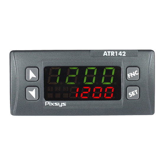
Page 14: Display And Keys Functions
Display and keys functions ATR 142 Numeric indicators (Display) Normally displays the process. During the confi guration phase, it displays the parameter 1234 being inserted. Normally displays the setpoint. During the confi guration phase, it displays the parameter 1234 value being inserted.
-
Page 15: Keys
Keys • Allows to decrease main setpoint. • During configuration phase, allows to slide through parameters. Together with key it “ m ” modifies them. • Pressed after key it allows to decrease alarm setpoint. • Allows to increase main setpoint. •…
-
Page 16: Auto-Tune
Auto-Tune Tuning procedure calculates the controller parameters and can be manual or automatic according to selection on parameter 46 tune Manual tuning Manual procedure allows the user greater flexibility to decide when to update PID algorithm parameters. The procedure can be activated in two ways. •…
-
Page 17: Automatic / Manual Regulation For % Output Control
Automatic/manual tuning cannot be enabled if the Soft start is active. Automatic / manual regulation for % output control This function allows to select automatic functioning or manual command of the output percentage. Parameter 49 Au.ma. , can select two methods. •…
-
Page 18: Memory Card (Optional)
Maintenance time Cycle starts at each activation Mantenimento Setpoint 2 Cooling of the controller, or via Max Power Ra reddamento Max Potenza digital input if it is enabled Setpoint 1 Rising gradient for this type of functioning Gradiente di salita (parameter 50 dGt.i.
-
Page 19: Loading Default Values
Loading default values This procedure allows to restore factory settings of the device Press Effect Display 1 shows 0000 with the 1st digit FNC for 3s. flashing, while display 2 shows pass Change the flashing digit and move to the “…
-
Page 20: Digital Input Functions
For the calibration procedure refer to the following table: Press Eff ect Place the sensor on the Exit parameters minimum operating confi guration. Display 2 position (associated shows the writing Latc. with Lo.L.i. ) Place the sensor on the Set the value to maximum operating “…
-
Page 21
2t.s. : Switch two thresholds setpoint: with open contact ATR142 regulates on SET1; with closed contact regulates on SET2; 2t.s.i. : Switch two thresholds setpoint: setpoint selection is done by an impulse on digital input; 3t.s.i. : Switch three thresholds setpoint by an impulse on digital input;… -
Page 22: Dual Action Heating-Cooling
8.12 Dual action heating-cooling ATR142 is suitable also for systems requiring a combined heating-cooling action. Main command output must be configured foe hearting PID ( act.t. = Heat and p.b. must be greater than 0), and one of the alarms ( AL. 1 or AL. 2 ) must be configured as cooL. Command output must be connected to the actuator responsible for heat, while the alarm output will control cooling action.
-
Page 23
x = COOL x = COOL x = COOL < 0 < 0 < 0 (HEAT) (HEAT) (HEAT) COMMAND OUTPUT (HEAT) ACTIVE COMMAND OUTPUT (HEAT) ACTIVE COMMAND OUTPUT (HEAT) ALARM OUTPUT (COOL) ACTIVE ACTIVE… -
Page 24: Timer Operation
Timer operation Timer operation is enabled by parameter 63 tmr.f. To modify duration of counting time, follow the steps below: Press Effect Press until tim. 1 or tim. 2 visualized on display 1. Increase or decrease Digits on display 2 2 “ n ” and “ m ” time value for the changes.
-
Page 25: Dual Sequential Timer
Press Effect FNC Press until tim. 1 or tim. 2 visualized on display 1. Back to point 1, after Start the Timer. Display selection of running 2 shows decrementing Timer time and Led “ n ” press “ n ” to stop switches on (fixed for timer 1, flashing for counting.
-
Page 26: Dual Timer Loop
Dual timer loop This option enables 2 Timers and the time value is selectable by the operator. At elapsing of one Timer, the other one will automatically start and this sequence is repeated cycling. To achieve operation of dual timer loop set the parameter 63 tmr.f.
-
Page 27: Serial Communication
Alarm active at elapsing of Timer2 until any key is pressed. Option not t.2.e.a. Timer 2 End Alarm available for Dual sequential Timer and Dual Timer Loop. t.2.w.e. Timer 2 Warning Alarm active for the last 5” of Timer2 Expiring t.
-
Page 28
At each parameter configuration, the device stores changed values in the EEPROM memory (100000 writing cycles), while setpoints are stored with a delay of 10 seconds after last modification. NB: modifications made to words different from those described in the following table can lead to instrument malfunction. -
Page 29
Loading default values: 9999 restore all values 9998 restore all values except for baud-rate and slave address 9997 restore all values except for slave address 9996 restore all values except for baud-rate Process (with tenths of degree for 1000 temperature sensors; digits for linear sensors) 1001 Setpoint1… -
Page 30
Error flags Bit0 = Eeprom writing error Bit1 = Eeprom reading error Bit2 = Cold junction error 1013 Bit3 = Process error (sensor) Bit4 = Generic error Bit5 = Hardware error Bit6 = Master off-line Bit7 = Missing calibration data Cold junction temperature 1014 (tenths of degree) -
Page 31
Visualized Alarm 2 (decimal as 1106 R/W EEPROM display) Setpoint gradient (decimal as 1107 EEPROM display) Heating output percentage 1108 (0-1000) Heating output percentage 1109 (0-100) Cooling output percentage 1110 (0-1000) Cooling output percentage 1111 (0-100) 2001 Parameter 1 R/W EEPROM 2064 Parameter 64 R/W EEPROM… -
Page 32: Master
Word serial outputs Bit 0 = Q1 relay 3019 R/W 0 Bit 1 = Q2 relay Bit 2 = SSR Word serial outputs state if off-line Bit 0 = Q1 relay 3020 R/W 0 Bit 1 = Q2 relay Bit 2 = SSR 3021 Word serial process R/W 0…
-
Page 33
Description mast. w.pro. Write process value Write Process r.w.co. Write and read command setpoint Read/Write value Command Setpoint w.ou.p. Write output percentage rated by P.I.D. Write Output function (Range 0-10000) Percentage r.w.a. 1 Read/Write Alarm 1 Write and read alarm 1 setpoint value The read/written value might be rescaled according to the proportion described in the following table: Value limits input… -
Page 34: Master Mode Remote Process
The input value (included between minimum and max limit) is linearly converted into the retransmitted value which is included between min and max output value. Rescaling is not executed if parameters Lo.L.r. and up.L.r. have the same value. 10.2.2 Master Mode Remote process To enable this function it is necessary to select r.pro.
-
Page 35: Table Of Configuration Parameters
Display 1 shows the first parameter and confirm display 2 shows the value. Slide up/down 4 “ n ” and “ m ” through parameters Enter the new data Increase or decrease which will be saved the value displayed on releasing the by pressing firstly “…
-
Page 36
ATR142-ABC Command Alarm 1 Alarm 2 c.o1 c.o2 c.ssr Q1(opens) Q2(closes) c.uaL. ATR142-ABC-T Command Alarm 1 c.o1 c.ssr Q1(opens) SSR(closes) — c.uaL. Sensor SEN. analogue input configuration. Tc-K -260…1360°C > Default Tc. k Tc-S -40…1760°C Tc. s Tc-R -40…1760°C Tc. r Tc-J -200…1200°C Tc. J PT100 -200…600°C PT100 -200…140°C… -
Page 37
Decimal Point d.p. select number of displayed decimal points. > Default 1 Decimal 2 Decimals 0.00 3 Decimals 0.000 Lower Limit Setpoint Lo.L.s. lower limit setpoint. -999…+9999 [digit ] (degrees.tenths for temperature sensors) Default: 0. Upper Limit Setpoint UP.L.S. upper limit setpoint. -999…+9999 [digit ] (degrees.tenths for temperature sensors) Default: 1750. -
Page 38
Offset Calibration o.caL. number added/subtracted to process value visualized on display (usually correcting the ambient temperature value). -999…+1000 [digit ] for linear sensors and potentiome- ters. -99.9…+100.0 (degrees.tenths for temperature sensors). > Default: 0.0. Gain Calibration G.caL. this % is multiplied with displayed value to calibrate the process value. -
Page 39
Command Hysteresis c. HY. hysteresis in ON/OFF or dead band in P.I.D. -999…+999 [digit ], (degrees.tenths for temperature sensors) > Default: 0.0 Command Delay c. de. (only in ON/OFF functioning).(In case of servo valve it also functions in PID and represents the delay between the opening and closure of the two contacts). -
Page 40
Cycle Time t.c. Cycle time for time-proportioning output (10/15sec for PID contactors, 1 sec for PID on SSR or value declared by manufacturer for motorised valves) 0.1-300.0 sec. > Default: 10.0. For motorised valve min. time is 1.0 sec Output Power Limit o.po.L. -
Page 41
Alarm 1 State Output a. 1 .s.o. alarm 1 output contact and intervention type (n.o. start) Normally open, active at start > n.o. s. Default (n.c. start) Normally closed, active at start. n.c. s. (n.o. threshold) Normally open, active on n.o. t. reaching alarm (n.c. -
Page 42
Alarm 1 Delay a. 1 .de. -180…+180 Sec. > Default: 0. Negative: delay at exit from alarm Positive: delay at starting of alarm Alarm 1 Setpoint Protection a. 1 .s.p. does not allow the user to modify setpoint. > Default Free Locked Lock. -
Page 43
Alarm 2 State Output a.2.s.o. alarm 2 output contact and intervention type. (n.o. start) Normally open, active at start. > n.o. s. Default (n.c. start) Normally closed, active at start. n.c. s. (n.o. threshold) Normally open, active on n.o. t. reaching alarm (n.c. threshold) Normally closed, active on n.c. t. -
Page 44
Alarm 2 Setpoint Protection a.2.s.p. Alarm 2 set protection. Does not allow operator to change setpoint value. > Default free Locked Lock. Locked and hidden Hide Cooling Fluid coo.f. select type of cooling fluid for Heating/Cooling PID (parameter 7.12) Air > Default Water Proportional Band Multiplier p.b.m. -
Page 45
9 Samples Mean 9. s.m. 10 Samples Mean > Default 10.s.m. 11 Samples Mean 11.s.m. 12 Samples Mean 12.s.m. 13 Samples Mean 13.s.m. 14 Samples Mean 14.s.m. 15 Samples Mean 15.s.m. Conversion Frequency c.frn. Frequency of sampling for analogue-digital converter. 242 Hz Max ADC conversion frequency 242H. -
Page 46
7 Samples Mean 7. s.m. 8 Samples Mean 8. s.m. 9 Samples Mean 9. s.m. 10 Samples Mean 10.s.m. Tune tune tuning type selection Disabled > Default dis. Automatic. PID parameters are calculated at auto each activation and/or change of setpoint. Manual. Launch by keyboard or by digital input. man. -
Page 47
Digital Input dGt.i. Digital input functioning. (parameter 7.11) Parameter 48 selection must be cont. or Pr.cy. Disabled > Default dis. Start/Stop st.st. Run n.o. rn.n.o. Run n.c. rn.n.c. L.c.n.o. Lock Conversion n.o. (Lock visualisation on display with N.O. contact) Lock Conversion n.c. (Lock visualisation on L.c.n.c. -
Page 48
User Menu Cycle Programmed u.m.c.p. Allows the rising/falling gradient and the maintenance time to be changed from the user menu in pre-program- med cycle functioning. (parameter 7.7) Disabled > Default dis. Rising Gradient (modify gradient) r i.Gr. Maintenance Time (modify time) ma.t.i. -
Page 49
Slave Address sL.ad. select slave address for serial communication 0 – 255 > Default: 254. Serial Delay se.de. select serial delay 0 – 100 milliseconds > Default: 20. Master mast. select master mode. (parameter 9.2) Disable > Default dis. Write Process w.pro Read Write Command Setpoint r.w.co. -
Page 50: Alarm Intervention Modes
Timer Function tmr.f. enable 1 or 2 Timers which may be set from user menu and which can be related to alarms. (parameter
 Disable > Default dis. Single Timer Seconds s.tm.s. Double Timer Seconds d.tm.s. d.s.t.s. Double Sequential Timer Seconds Double Timer Loop Seconds d.t.L.s.
 -
Page 51
Hysteresis parameter Absolute alarm with < 0 controller heating Alarm Spv. functioning (Parameter 11 act.t. selected Heat ) and hysteresis value less than Time “0” (Parameter 28 a. 1 .Hy. < 0). * Alarm output Time Absolute alarm with controller cooling Hysteresis… -
Page 52
13.b Absolute alarm or threshold alarm referring to setpoint command ( selection) a.c.aL. Absolute alarm refers to the command set, with the controller in heating Command Spv functioning (Parameter 11 Hysteresis parameter act.t. selected Heat ) and > 0 hysteresis value greater Alarm Spv than “0”… -
Page 53
13.d Upper Deviation Alarm ( selection) H.d.aL. Alarm Spv Upper deviation alarm Hysteresis value of alarm setpoint parameter > 0 greater than “0” Command Spv hysteresis value greater than “0” (Parameter 28 Time a. 1 .Hy. > 0). ** Alarm output Upper deviation alarm Command Spv… -
Page 54: Table Of Anomaly Signals
Hysteresis parameter > 0 Lower deviation alarm Alarm Spv value of alarm setpoint less than “0” and Command Spv hysteresis value greater than “0” (Parameter 28 Time a. 1 .Hy. > 0). ** Alarm output * The example refers to alarm 1; the function can also be enabled for alarm 2 on model that include it.
-
Page 55
Check the serial Off-line in master mode E-06 connection, baud-rate remote process ser.e. and device ID. E-08 Missing calibration data Call Assistance sYs.e. Notes User manual — ATR142- 55… -
Page 56
Table of configuration parameters Command Output c.out Sensor SEN. Decimal Point d.p. Lower Limit Setpoint Lo.L.s. Upper Limit Setpoint UP.L.S. Lower Linear Input Lo.L.i. Upper Linear Input up.L.i. Latch On Function Latc. Offset Calibration o.caL. Gain Calibration G.caL. Action type act.t. -
Page 57
Alarm 2 Reset a.2.re. Alarm 2 State Error a.2.s.e. Alarm 2 Led a.2.Ld. Alarm 2 Hysteresis a.2.HY. Alarm 2 Delay a.2.de. Alarm 2 Setpoint Protection a.2.s.p. Cooling Fluid coo.f. Proportional Band Multiplier p.b.m. Overlap/Dead Band ov.d.b. Cooling Cycle Time co.t.c. Conversion Filter c.fLt. -
Page 58
Prima di utilizzare il dispositivo leggere con attenzione le informazioni di sicurezza e settaggio contenute in questo manuale. PIXSYS s.r.l. www.pixsys.net sales@pixsys.net — support@pixsys.net online assistance: http://forum.pixsys.net 2300.10.092-RevL Software Rev. 1.21 110117…
Описание
- Электронный термостат с фукцией PID-регулятора или включение/отключение
- Класс защиты IP54 (передняя панель)
- Разрешение 1 / 0,1 / 0,01 / 0,001 в зависимости от типа датчика
- последовательный интерфейс RS-485
Технические характеристики
| Тип | Тип датчика | Питание | Выходы |
| ATR142 | J, K, PT100 | 24…230 VAC/DC | 1 вых. упр. твердот. реле, по 1 реле 8А и 5А |
| ATR243 | * (прогр) | 24…230 VAC/DC | 1 вых. упр. твердот. реле, по 1 реле 5А, аналог. выход 0…10В / 4…20мА |
*Резистивные датчики типов PT-100, NI-100, PT-500, PTC, NTC, термопары типов К, J, S, R, аналоговые сигналы 0/4…20 мА, 0…10 В, патенциометры 6 кОм, 150 кОм
Технический паспорт Pixus ATR142 Универсальный контроллер с дисплеем и интерфейсом RS-485 (752 КВ)

Автоматический регулятор температуры
Модель: ATR142
Производитель: Pixsys
Автоматический регулятор температуры, трехпозиционный, размеры — 32х74мм. Двойной красно-зеленый экран одновременно отображает текущие и заданные значения. Импульсный источник питания с расширенным диапазоном потребляемого тока 24…230В переменного/постоянного тока, позволяет обойтись без настройки переключателей.
Аналоговый вход автоматического регулятора температуры по выбору для термопар типов J, K, S, R, терморезисторов PT100, PTC 1К, NI100, NTC 10K (холодильная промышленность) и PT500/PT1000 (широко используется при кондиционировании воздуха), 0…1В, 0…10В, 0…20мA, 4…20мA. Возможно считывание показаний с потенциометров со шкалой до 6KΩ и 150KΩ, и использование функции «Latch on» (Захват) для быстрой калибровки и установки минимального, максимального и нулевого значений с помощью кнопок на передней панели (см. Заметки по применению).
Автоматический регулятор температуры имеет возможность установки трех контрольных значений, для функций управления и сигнализации. Они могут быть соотнесены с двумя релейными выходами или с выходом SSR. Основное реле контрольного выхода 8А. Реле сигнализации 5А (режимы срабатывания сигнализации: порог, полоса, отклонение; возможность ручного сброса выходного сигнала с помощью клавиатуры на лицевой панели для Ограничения работы автоматического регулятора температуры; функция включения с задержкой). Алгоритм Открыть/Закрыть для управления электроприводными клапанами.
Программные функции автоматического регулятора температуры: Вкл/Выкл, PID+ автоматическая настройка и PID Тепло-Холод с нейтральной зоной. Доступна модель с одним выходом (1 реле + SSR), с последовательным интерфейсом RS485 и Modbus-RTU / Slave протоколом для использования в системах диспетчерского управления.
Крышка для лицевой панели автоматического регулятора температуры(дополнительная опция) соответствует классу защиты IP65.
Как опция доступна карта памяти для сохранения параметров, может комплектоваться батарейкой, что позволяет не включать питание прибора.
Программное обеспечение LabSoftView для Windows позволяет установку и контроль параметров через ПК.
Отдельно можно заказать специальную версию программного обеспечения, которая объединяет в приборе простую систему автоматического управления и функцию Таймера (с прямым/обратным отсчетом времени для и/или Паузы/Работы).
Продукт сертифицирован согласно ГОСТ. Номер сертификата 0332323 от 14.07.2010.
Thank you for choosing a Pixsys controller.
With the ATR142 model Pixsys makes available in a single device all
the resources relevant to sensor input and actuators command, in
addition to the extended power range 24…230 Vac/Vdc. With 17
sensors to select and outputs configurable as relay or SSR command,
the user or retailer can reduce warehouse stock by rationalising
investment and device availability. The series is completed with
models equipped with serial communication RS485 Modbus. The
configuration is further simplified by the Memory cards which are
equipped with internal battery and therefore don’t require cabling to
power the controller.
The range of ATR142 controllers comes in two versions. Refer to the
table below to easily select your preferred model.
Models available, with power 24…230 Vac/Vdc +/-15% 50/60Hz – 3,5VA
ATR142-ABC
ATR142-ABC-T
1
2
Model Identification
2 relays (8A+5A) + 1 Ssr
1 relays 8A + 1 Ssr + Rs485
3
 |
[Page 1] Pixsys ATR142 ATR142 |
 |
[Page 2] Pixsys ATR142 Summary 1 Introduction ………………………………………………………………………………………….. 3 2 Model Identification……………………………………………………………………………….. |
 |
[Page 3] Pixsys ATR142 3 1 Introduction Thank you for choosing a Pixsys controller. With the ATR142 model Pixsys makes available in a single device all the resources relevant to sensor input and actuators command, in addition to the extended power r… |
 |
[Page 4] Pixsys ATR142 4 3 Technical Data 3.1 General Features Displays 4 0.40 inch displays + 4 0.30 displays Operating temperature 0-45°C, humidity 35..95uR% Sealing IP65 front panel (with gasket) IP30 casing and IP20 terminals Material Polycarbonate… |
 |
[Page 5] Pixsys ATR142 5 3.3 Software Features Regulation algorithms ON-OFF with hysteresis. P, PI, PID, PD with proportional time Proportional band 0…9999°C or °F Integral time 0,0…999,9 sec (0 excluded) Derivative time 0,0…999,9 sec (0 e… |
 |
[Page 6] Pixsys ATR142 6 5 Electrical wirings Although this controller was designed to resist noises in industrial environments, pease notice following safety guidelines: • Separate the feeder line from the power lines. • Avoid placi… |
 |
[Page 7] Pixsys ATR142 7 Power Switching power supply with extended range 24…230 Vac/dc ±15% 50/60Hz – 5,5VA. AN1 Analogue Input For thermocouples K, S, R, J. • Comply with polarity • For possible extensions, use a compensated wire an… |
 |
[Page 8] Pixsys ATR142 8 Examples of Connection for linear input For signals 0….10V Comply with polarity For signals 0/4….20mA with three-wire sensor Comply with polarity C=Sensor output B=Sensor ground A=Sensor power For signals 0/4….20mA… |
 |
[Page 9] Pixsys ATR142 9 Relay Q1 Output Capacity: Q1 — 8A/250V~ for resistive loads Q2 — 5A/250V~ for resistive loads SSR output SSR command output 12V/30mA Digital Input on ATR243-20ABC Digital input using parameter . The use of digital inp… |
 |
[Page 10] Pixsys ATR142 10 6.2 Meaning of Status Lights (Led) 3 ON when the output command is on. For motorised valve command, led in on when valve is opening and blink when closing. 4 ON when alarm 1 is on. 5 ON when alarm 2 is on. 6 ON when … |
 |
[Page 11] Pixsys ATR142 11 7 Controller Functions 7.1 Modifying Main Setpoint and Alarm Setpoint Values The setpoint value can be changed from the keyboard as follows: Press Effect Operation 1 or Value on display 2 changes Increases or decrea… |
 |
[Page 12] Pixsys ATR142 12 7.4 Automatic Tuning Automatic tuning activates when the controller is switched on or when the setpoint is modified to a value over 35%. To avoid an overshoot, the treshold where the controller calculates the new PID parameters is de… |
 |
[Page 13] Pixsys ATR142 13 Press the key to show ; it is now possible, during the process display, to change the output percentage using the keys and . To return to automatic mode, using the same procedure, select on display 2: the led… |
 |
[Page 14] Pixsys ATR142 14 7.8 Memory Card (optional) Parameters and setpoint values can be duplicated from one controller to another using the Memory card. There are two methods: • With the controller connected to the power supply Insert the memory card when… |
 |
[Page 15] Pixsys ATR142 15 7.9 Loading default values This procedure makes it possible to restore factory settings of the instrument. Premere Effetto Eseguire 1 F N C for 3 seconds. Display 1 shows with the 1st digit flashing, while… |
 |
[Page 16] Pixsys ATR142 16 To use the LATCH ON function configure as you wish the parameter . 3 For the calibration procedure refer to the following table: Press Effect Operation 1 F N C Exit parameters configuration. Display 2 shows the writing … |
 |
[Page 17] Pixsys ATR142 17 8.1 Digital Input Functions Digital input is programmable for several functions which are useful to simplify controller operability. Select the desired function on parameter 50 . 1. Hold function (enabled by setting or ) allows to … |
 |
[Page 18] Pixsys ATR142 18 8.2 Dual Action Heating-Cooling ATR142 is also suitable also for systems requiring a combined heating- cooling action. The command output must be configured as Heating PID ( = and with a greater than 0), and one of the alarms … |
 |
[Page 19] Pixsys ATR142 19 The following figure shows an example of dual action PID (heating- cooling) with = 0 and = 0. |
 |
[Page 20] Pixsys ATR142 20 The parameter has the same meaning as the heating time cycle . The parameter (cooling fluid) pre-selects the proportional band multiplier and the cooling PID time cycle basing on the type of cooling fluid: Cooling… |
 |
[Page 21] Pixsys ATR142 21 Modbus RTU protocol features Baud-rate Can be selected on parameter 70 4800bit/sec 9600bit/sec 19200bit/sec 28800bit/sec 38400bit/sec 57600bit/sec Format 8, N, 1 (8bit, no parity, 1 stop) Supported functions WOR… |
 |
[Page 22] Pixsys ATR142 22 1008 Outputs status (0=off, 1=on) Bit 0 = Q1 relay Bit 1 = Q2 relay Bit 2 = SSR RO 0 1009 Heating output percentage (0-10000) RO 0 1010 Cooling output percentage (0-10000) RO 0 1011 Alarms status (0=none, 1=active) Bit0 = Ala… |
 |
[Page 23] Pixsys ATR142 23 1106 Allarme2 visualized (decimal as display) R/W EEPROM 1107 Setpoint gradient (decimal as display) RO EEPROM 1108 Heating output percentage (0-1000) RO 0 1109 Heating output percentage (0-100) RO 0 1110 Cooling output percentag… |
 |
[Page 24] Pixsys ATR142 24 9.2 Master The device works as master if the value selected on parameter 59 is other than . 9.2.1 Master Mode in retransmission Selecting this mode, the device will write the value to be retransmitted at the address select… |
 |
[Page 25] Pixsys ATR142 25 The read/written value might be rescaled according to the proportion described in the following table: Limiti valore ingresso Limiti valore riscalato Min. Max. Min. Max. Write Process Lower Limit Input Upper Limit Input L… |
 |
[Page 26] Pixsys ATR142 26 10 Configuration 10.1 Modify Configuration Parameter For configuration parameters see paragraph 11. Press Effect Operation 1 F N C for 3 seconds. Display 1 shows with the 1st digit flashing, while display 2 shows… |
 |
[Page 27] Pixsys ATR142 27 11 Table of Configuration Parameters The following table includes all parameters. Some of them will not be visible on the models which are not provided with relevant hardware features. no. Display Parameter description Entering range … |
 |
[Page 28] Pixsys ATR142 28 no. Display Parameter description Entering range 2 Sensor Analog input configuration Tc-K (-260…1360°C) (Default) Tc-S (-40…1760°C) Tc-R (-40…1760°C) Tc-J (-200…1200°C) PT100 (-200…600°C) PT100 (-200�… |
 |
[Page 29] Pixsys ATR142 29 no. Display Parameter description Entering range 6 Lower Linear Input Lower range limit An1 only for linear input -999…+9999 digit* Default: 0. 7 Upper Linear Input Upper range limit An1 only for linear input -999…+9999 di… |
 |
[Page 30] Pixsys ATR142 30 no. Display Parameter description Entering range 16 Command Delay Command delay (only in ON/OFF functioning). (In case of servo valve it also functions in PID and represents the delay between the opening and closure of the two … |
 |
[Page 31] Pixsys ATR142 31 no. Display Parameter description Entering range 24 Alarm 1 State Output Alarm 1 output contact and intervention type (n.o. start) Default Normally open, active at start (n.c. start) Normally closed, active at start (n.o. thr… |
 |
[Page 32] Pixsys ATR142 32 no. Display Parameter description Entering range 31 Alarm 2 Alarm 2 selection. Alarm intervention is associated with AL2 (Disabled) Default (Absolute Alarm) (Band Alarm) (High Deviation Alarm) (Low Deviation Alarm) … |
 |
[Page 33] Pixsys ATR142 33 no. Display Parameter description Entering range 37 Alarm 2 Delay Alarm 2 delay -180…+180 Seconds Negative: delay in alarm output phase. Positive: delay in alarm entry phase. Default: 0. 38 Alarm 2 Setpoint Protect… |
 |
[Page 34] Pixsys ATR142 34 no. Display Parameter description Entering range 43 Conversion Filter ADC filter: number of means on analog-digital conversions (Disabled) (2 Samples Mean) (3 Samples Mean) (4 Samples Mean) (5 Samples Mean) (6 Samples Mean) (… |
 |
[Page 35] Pixsys ATR142 35 no. Display Parameter description Entering range 45 Visualisation Filter Visualisation filter (Disabled) Default (Pitchfork filter) (First Order) (First Order with Pitchfork) (2 Samples Mean) (3 Samples Mean) (4 Samples Mean… |
 |
[Page 36] Pixsys ATR142 36 no. Display Parameter description Entering range 48 Operating Mode Select operating mode (Controller) Default (Programmed Cycle) (2 Thresholds Switch) (2 Thresholds Switch Impulsive) (3 Thresholds Switch Impulsive) (4 Thre… |
 |
[Page 37] Pixsys ATR142 37 no. Display Parameter description Entering range 52 Maintenance Time Maintenance time for pre-programmed cycle 00.00-24.00 hh.mm Default: 00.00. 53 User Menu Cycle Programmed Allows the rise gradient and the maintenanc… |
 |
[Page 38] Pixsys ATR142 38 no. Display Parameter description Entering range 59 Master Select the master mode (Disable) Default (Write Process) (Read/Write Command Setpoint) (Write Output Percentage) (Read/Write Alarm 1 Setpoint) (Read Proces… |
 |
[Page 39] Pixsys ATR142 39 12 Alarm Intervention Modes Absolute Alarm or Threshold Alarm ( selection ) On On Off Off Pv > 0 Hysteresis parameter Time Alarm output Alarm Spv Absolute alarm with controller in heating functioning (Par.11 … |
 |
[Page 40] Pixsys ATR142 40 On On Off Off Pv < 0 Hysteresis parameter Time Alarm output Alarm Spv Absolute alarm with controller in cooling functioning (Par.11 selected ) and hysteresis value less than “0” (Par.28 < 0). N.B.: The exa… |
 |
[Page 41] Pixsys ATR142 41 Band Alarm ( selection ) On On On Off Off Off Pv Time Alarm output Comand Spv > 0 Hysteresis parameter Alarm Spv Alarm Spv Band alarm hysteresis value greater than “0” (Par.28 > 0). N.B.: The example ref… |
 |
[Page 42] Pixsys ATR142 42 Upper Deviation Alarm ( selection ) On On Off Off Pv Time Alarm output Comand Spv > 0 Hysteresis parameter Alarm Spv Upper deviation alarm value of alarm setpoint greater than “0” and hysteresis value greater th… |
 |
[Page 43] Pixsys ATR142 43 Lower Deviation Alarm ( selection ) On On Time Off Off Alarm output Pv Comand Spv > 0 Hysteresis parameter Alarm Spv Lower deviation alarm value of alarm setpoint greater than “0” and hysteresis value greater t… |
 |
[Page 44] Pixsys ATR142 44 13 Table of Anomaly Signals In case of malfunctioning of the system, the controller switches off the regulation output and displays the type of anomaly. For example the controller will signal the breakage of any connected thermocouple b… |
 |
[Page 45] Pixsys ATR142 45 14 Summary of Configuration parameters Date: Model ATR142: Installer: System: Notes: Command output type selection Analog input configuration Number of decimal points Lower limit setpoint Upper limit … |
 |
[Page 46] Pixsys ATR142 46 State of OUT2 led Alarm 1 hysteresis Alarm1 delay Alarm 1 set protection Alarm 2 selection Alarm 2 output contact and intervention type Reset type of alarm 2 contact State of contact for alarm 2 output … |
 |
[Page 47] Pixsys ATR142 47 Seelct address for retransmission Lower limit of retransmission range Upper limit of retransmission range Note |
 |
[Page 48] Pixsys ATR142 48 |
 |
[Page 49] Pixsys ATR142 49 |
 |
[Page 50] Pixsys ATR142 50 |
 |
[Page 51] Pixsys ATR142 51 |
 |
[Page 52] Pixsys ATR142 52 PIXSYS Via Tagliamento, 18 30030 Mellaredo di Pianiga (VE) www.pixsys.net e-mail: [email protected] — [email protected] Software Rev. 1.04 2300.10.093-RevC 200608 *2300.10.093-C* … |