перейти к содержанию
![]() ИНСТРУКЦИЯ ПО
ИНСТРУКЦИЯ ПО
РУКОВОДСТВО
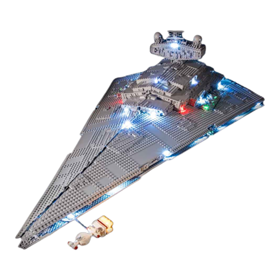
75190 Комплект освещения для звездного разрушителя Первого Ордена

Световой комплект для звезды первого порядка
Разрушитель 75190
Спасибо
Для покупки этого продукта. Чтобы добиться идеального эффекта скрытой линии, мы используем очень тонкую авиационную проволоку с высокой устойчивостью к натяжению и давлению. Однако из-за его тонкой природы будьте осторожны, чтобы не прорезать его, так как он может быть подвержен сдвигу во время установки. Всегда будьте осторожны, чтобы не прижать кирпичи к проволоке.
Давайте начнем
если вы столкнетесь с какими-либо проблемами, пожалуйста, не стесняйтесь обращаться через support@gameofbricks.eu Обратите внимание, что мы предлагаем 2 года бесплатного обслуживания светового комплекта.
Шаг 1


Шаг 2


Шаг 3


Шаг 4


Подсоедините световой комплект к батарейному отсеку, и установка будет завершена. Если вы хотите использовать другой источник питания, убедитесь, что максимальный объемtagе — 6 В.
![]()
Подсоедините световой комплект к батарейному отсеку, и установка будет завершена. Если вы хотите использовать другой источник питания, убедитесь, что максимальный объемtagе — 6 В.
![]()
Документы / Ресурсы
-
Bookmarks
Quick Links
Related Manuals for LIGHT MY BRICKS 75252
Summary of Contents for LIGHT MY BRICKS 75252
-
Page 2: Package Contents
Please note: This page lists instructions for the LED light kit only. Package Contents: 34x Cool White 30cm Bit Lights 3x Flashing White 30cm Bit Light 4x Flashing Red 30cm Bit Light 5x Cool White 30cm Large Bit Lights 20x Green 15cm Micro Bit Lights 11x White 30cm Micro Bit Lights Effects and Expansion Boards 1x Pulse Effects Board…
-
Page 3
LEGO Pieces: 28x Trans Clear Round Plate 1×1 4x Trans Light Blue Round Plate 1×1 1x Trans Clear Tile 1×2 1x Trans Black Cone 1×1 with Top Groove 1x Trans Clear Slope 30 1x1x2/3 Important things to note: Laying cables in between and underneath bricks Cables can fit in between and underneath LEGO®… -
Page 4
CAUTION: Forcing LEGO® to connect over a cable can result in damaging the cable and light. Connecting cable connectors to Expansion Boards Take extra care when inserting connectors to ports of Expansion Boards. Connectors can be inserted only one way. With the expansion board facing up, look for the soldered “=” symbol on the left side of the port. -
Page 5
Connecting Micro Cable connectors to Micro Expansion Board Ports Take extra care when inserting the micro connectors to micro ports of Micro Expansion Boards. Connecting Micro Bit Lights to Micro Expansion Boards is similar to connecting lights and cables to Strip Lights. With the expansion board facing up, ensure the side of the connector with the wires exposed is facing down. -
Page 6
When installing Bit Lights under LEGO® pieces, ensure they are placed the correct way up (Yellow LED component exposed). You can either place them directly on top of LEGO® studs or in between. OK, Let’s Begin! 1.) Start by disconnecting the following sections from the top of the ship. -
Page 10
Use your LEGO removal tool to disconnect the following pieces to allow us to remove the two panels that make up the entire left section of the ship. -
Page 12
Disconnect the Tantive via the trans clear clip… -
Page 13
2.) We will now install seven lights along the side of the ship. Take a Cool White 30cm Bit Light and with the cable facing up, place it over the following stud near the front of the ship. Secure the Bit Light in place by connecting a provided Trans Clear Round Plate 1×1 over the top. -
Page 14
Bring the cable over towards the inside of the ship, then feed the cable underneath the following technic pieces. 3.) Take out another Cool White 30cm Bit Light and install it to the next stud down the side of the ship as shown below. Secure it in place with another provided Trans Clear Round Plate 1×1. -
Page 15
4.) Using the same method used in previous steps, install another 2x Cool White 30cm Bit Lights to the following studs along the side of the ship. Follow the images below to ensure you install the lights to the correct location. Secure them in place using 2x Trans Clear Round Plates 1×1. -
Page 17
5.) Take a 12-Port Expansion Board and connect the four Bit Light Cables, then take a 50cm Connecting Cable connect it to another spare port on the 12-Port Expansion Board. -
Page 18
Bring the other end of the 50cm connecting cable toward the back of the ship and feed it underneath the large red technic plate sections going across the centre. Pull the cable out from the other side and connect it to a new 12-Port Expansion Board. -
Page 19
6.) We will now install another three lights to the side of the ship to thefollowing positions. -
Page 20
First disconnect the following pieces, then install a Cool White 30cm Bit Light to the following stud, securing it in place using a provided Trans Clear Round Plate 1×1. Once installed, reconnect the pieces we removed earlier. -
Page 21
Connect the Bit Light to the second 12-Port Expansion Board towards the back of the ship. 7.) Install another 2x Cool White 30cm Bit Lights to the following positions, securing them in place using 2x Trans Clear Round Plates 1×1. Ensure you following the below images to correctly lay the cables underneath pieces, then connect both lights to the 12-Port Expansion Board in previous step. -
Page 24
Secure the last Bit Light cable underneath the following 2×4 tile. Disconnect it, lay the cable in between studs, then reconnect the tile over the top. 8.) Take a new 50cm Connecting Cable and connect it to a spare port on the first 12-Port Expansion Board toward the front of the ship. -
Page 25
From underneath of the ship, pull the cable down and connect it to a 2-Port Expansion Board. Take your USB Power Cable and connect it to the other port. Connect the USB Connector side to a USB Power Bank wall adaptor (sold separately) and turn it ON to test all the lights installed to the left side of the ship are working OK. -
Page 27
Note: If you experience any issues with the lights not working and suspect an issue with a component, please try a different port on the expansion board to verify where the fault lies (with the light or expansion board). To correct any issues with expansion board ports, please view the section addressing expansion board issues on our online troubleshooting guide. -
Page 29
Take out a Green 15cm Micro Bit Light and carefully bend the LED component so that the side is facing the top. This will allow the LED to fit easily inside the canon hole. Take one of the cannon pieces and carefully thread the Micro Bit Light’s LED all the way inside the hole. -
Page 30
10.) Using the same method used in previous step, install another Green 15cm Micro Bit Lights to another cannon piece, then secure the cable underneath the stud and reconnect it to the 2×2 round plate. -
Page 31
Ensure both cables are laid in between the spaces of the plate, then reconnect the 2×2 rounded bottom plate. -
Page 32
11.) Turn this section around then install another 2x Green 15cm Micro Bit Lights to the cannons on this side. Secure the cables underneath studs of the cannon pieces, then reconnect both of them as shown below. -
Page 33
Lay both cables in between the spaces towards the back of the round 2×2 plate, then reconnect the hinge ball section followed by the 2×2 rounded bottom plate. -
Page 34
12.) Tuck the four cables underneath the base of the cannon, then twist the fourcables around each other all the way to the ends to form one larger cable. -
Page 35
Reconnect the cannon section back to to the side of the ship, then bring the cables inside the ship and connect them to a Micro 4-Port Expansion Board. -
Page 36
13.) Take a 15cm Connecting Cable and connect it to one of the larger ports on the Micro 4- Port Expansion Board. Connect the other end of the cable to the OUT port 1 on the Gun Effects Board. Take another 15cm Connecting Cable and connect it to the IN port (+5V) on the Gun Effects Board. -
Page 37
Turn your power ON to test the lights installed so far and to configure the Gun Effects Board. You can choose between 3 different shooting effects via the 3 way switch on the effects board. 1. Canon – 2 Fires – each channel firing at random rate 2. -
Page 39
Note: If you experience any issues with the lights not working and suspect an issue with a component, please try a different port on the expansion board to verify where the fault lies (with the light, expansion board, or effects board). To correct any issues with expansion board ports, please view the section addressing expansion board issues on our online troubleshooting guide. -
Page 40
Take a 15cm Connecting Cable and connect it to a spare port on the 12-Port Expansion Board on the back of the ship. Connect the other end of the cable to a new 12-Port Expansion Board, then feed the board underneath the technic pieces in the centre to bring it through to the other side. -
Page 41
15.) Carefully turn the ship around so we can install lights to the right side. Firstdisconnect the 2×4 tile and 2×2 rounded bottom plate to allow us to disconnect the two top panel sections. -
Page 43
16.) We will now install seven lights to the right side of the ship. Use the samemethod used for the side lights on the left side to install the first 4x Cool White 30cm Bit Lights, securing them in place using the provided 4x Trans Clear Round Plates 1×1. Follow the below images carefully to modify certain sections and feed the cables underneath the middle to connect to the 12-port expansion board on the other side. -
Page 48
Turn ON the power to test the four lights installed to the right side are working OK. Note: If you experience any issues with the lights not working and suspect an issue with a component, please try a different port on the expansion board to verify where the fault lies (with the light, expansion board, or effects board). -
Page 52
Secure the last Bit Light cable underneath the following 2×4 tile, then turn ON the power to test all the lights installed to the right side are working OK. -
Page 54
Note: If you experience any issues with the lights not working and suspect an issue with a component, please try a different port on the expansion board to verify where the fault lies (with the light, expansion board, or effects board). To correct any issues with expansion board ports, please view the section addressing expansion board issues on our online troubleshooting guide. -
Page 55
Using the same method used to install the lights to the laser cannons on the left side of the ship, install 4x Green 15cm Micro Bit Lights to this laser cannon. -
Page 58
Tuck the four cables underneath the base of the cannon, then twist the four cables around each other all the way to the ends to form one larger cable. -
Page 59
19.) Reconnect the laser cannon section to the right side of the ship, then connect the Micro Bit Light cables to the spare Micro 4-Port Expansion Board that we brought over from the other side (Step 14.) -
Page 60
Turn the power ON to test the cannons on the right side of the ship are working OK. Because they are connected to the same channel as the cannons on the left side, they should be all firing together in sync. Note: If you experience any issues with the lights not working and suspect an issue with a component, please try a different port on the expansion board to verify where the fault lies (with the light, expansion board, or effects board). -
Page 61
20.) We will now light up the docking bay underneath the ship. First, we willneed to disconnect the front bottom panel section on the right side. Disconnect the plate with handle from the very front of the ship, then disconnect the 2×2 rounded bottom plate securing the front and back panel together. -
Page 62
From the inside of the ship, locate and pull out the two orange technic pins that are securing the docking bay to the ship, then carefully remove the docking bay section by pulling it out from the bottom. -
Page 63
21.) Disconnect the Tie Fighter from the clip, then remove the grey mechanicalpiece and trans red round plate from it. -
Page 64
Take a Cool White 30cm Bit Light and bend the connector end of the cable into a hook as shown below. The hook will help us then thread the light through the Tie Fighter. Thread the connector side of the cable through the back of the Tie Fighter and out the bottom. -
Page 65
Before you completely pull the cable all the way out, carefully bend the Bit Light LED on a 90 degree angle so that it will face directly up and sit flat against the edge of the inside. Reconnect the Trans Red round plate, then bring the cable up and secure it in between the right wing and centre brick as shown below:… -
Page 66
Reconnect the mechanical clip piece, then reconnect the Tie Fighter to the docking bay. Caution – Do not forcefully push the mechanical clip piece all the way in or you may damage the Bit Light inside. -
Page 67
22.) Turn the docking bay around to the front and disconnect the followingpieces from the middle. -
Page 68
Lay the Bit Light cable down in between studs as shown below, then secure it by reconnecting sections over the top. -
Page 69
23.) Take a Cool White 30cm Bit Light and bend the cable up on a 90 degree angle around 1cm from the LED. Ensuring the LED is facing forward, place it in between studs as shown below. Secure it in place by reconnecting the following wall section. If you look from the other side, you should see the LED peaking out to shine onto the docking bay. -
Page 70
Repeat this step to install another Cool White 30cm Bit Light to the other wall section. Reconnect the remaining section on top. -
Page 71
24.) Turn the docking bay around to the back and disconnect sections from theright corner as shown below:… -
Page 72
Take a Flashing Red 30cm Bit Light and bend the cable up on a 90 degree angle around 1cm from the LED. Ensuring the LED is facing forward, place it in between studs as shown below. Secure it in place by reconnecting the corner pieces we removed earlier. If you look from the other side, you should see the LED peaking out in the corner to shine onto the docking bay… -
Page 73
25.) Turn the docking bay over to the back left corner and install anotherFlashing Red 30cm Bit Light to this side. -
Page 75
26.) Place the Docking Bay onto it’s back so we can access underneath. Lay thetop three cables down, then secure them underneath the blue 2×2 rounded bottom plates by first disconnecting them, laying the cables down, then reconnecting them over the top. Secure the flashing red bit light cables by threading each one inside the gaps as shown below. -
Page 77
Connect all five cables to a 6-Port Expansion Board then take a 5cm Connecting Cable and connect it to the remaining port. 27.) Bring the docking bay underneath the Star Destroyer, then thread theexpansion board through to the inside of the ship. Connect the other end of the 5cm Connecting Cable to the 12-port expansion board near the front.. -
Page 79
Bring the docking bay up and reconnect it to the ship by pushing the orange technic pins in to secure everything into place. -
Page 80
Turn on the power to test the lights installed to the docking bay are working OK. Reposition the Tie Fighter as desired. Note: If you experience any issues with the lights not working and suspect an issue with a component, please try a different port on the expansion board to verify where the fault lies (with the light, expansion board, or effects board). -
Page 81
28.) Ensure all cables from the docking bay lights and side of the ship lights areneatly tucked in before reconnecting the bottom right panel to the ship. Reconnect the 2×2 rounded bottom plate as well as the pieces that secure the front of the ship together. -
Page 82
29.) Carefully turn the ship around to the left side, then take the Tantive anddisassemble sections from the back jets as shown below:… -
Page 83
Take one of the jet sections of 4 and disassemble them, then take a White 30cm Micro Bit Light and place the LED inside the top of the white round brick. Flip the white round brick over and while ensuring the bit light is still inside, reconnect the white brick to the white 1×4 plate as shown below:… -
Page 84
Repeat this step to install 3x White 30cm Micro Bit Lights to the jets on this section ensuring the cables are all facing the same way. -
Page 85
With the cables all facing up, reconnect this section to the of the bottom side of the Tantive. 30.) Take the middle jet section and disconnect the three jets. Using the samemethod as per previous step, install 3x White 30cm Micro Bit Lights to this section ensuring the cables are all laid the same way. -
Page 87
Ensuring the cables are all facing up, reconnect this middle section to the back of the Tantive, then bring the three cables toward the right and secure them down underneath the corner of the red tile. 31.) Disassemble the last jet section and install the remaining 4x White 30cm Micro Bit Lights ensuring the cables are all facing the same way. -
Page 88
Turn the jet section over so that the cables are underneath of it and laid to the right side, then reconnect this section to the back of the Tantive. Bring all the cables out the right side as shown below:… -
Page 89
32.) Twist and wind all 11 cables around each other all the way to the ends toform one larger cable, then reassemble the Tantive and reconnect the trans clear bar underneath. -
Page 90
33.) Reconnect the Tantive to the side of the star destroyer, then wind thecables around the trans clear bar as shown below:… -
Page 91
Partially disconnect the bottom panel via the blue piece as shown below, then thread the cables through the gap we just created. Pull the cables out from the inside of the ship. -
Page 92
Reconnect the bottom panel via the blue piece to secure the cables and close up the gap in between the bottom and middle section. -
Page 93
34.) Connect 4 out of the 11 micro bit light cables to a new Micro 4-Port Expansion Board, then connect a 5cm Connecting Cable to the large port. Connect the other end of the 5cm Connecting cable to one of the OUT ports on a Flicker Effects Board (FFX). -
Page 94
Connect the remaining 7 micro bit light cables to a Micro 8-Port Expansion… -
Page 95
Board, then connect a new 5cm Connecting Cable to the large port on the board. Connect the other end of the 5cm cable to a different OUT port on the Flicker Effects Board. Take a 15cm Connecting Cable and connect it to the IN port on the Flicker Effects Board. Bring the other end of the 15cm cable over to the right and connect it to a spare port on the 12-Port Expansion Board toward the front of the ship. -
Page 96
Turn ON the power to test the lights for the Tantive are working and flickering OK. -
Page 97
Note: If you experience any issues with the lights not working and suspect an issue with a component, please try a different port on the expansion board to verify where the fault lies (with the light, expansion board, or effects board). To correct any issues with expansion board ports, please view the section addressing expansion board issues on our online troubleshooting guide. -
Page 98
Pull the cable out from the right side of the ship, then re-thread the cable through a higher position above. Pull the cable back out from the left side, then bring the 12-port expansion board to a higher position to allow you to reconnect the cable to the next available port. -
Page 99
Reposition both 12-Port Expansion Boards to higher positions on the back of the ship as shown below:… -
Page 100
36.) We will now install some lights to the tower and bridge. Follow the belowimages to disconnect the surrounding sections and pieces on top and on the sides. -
Page 101
Turn the ship around to the right side to continue to disconnect pieces and sections. -
Page 102
37.) Take a Cool White 30cm Bit Light and with the cable facing up, place it in between the following studs on the front of the tower. Secure the Bit Light in place by connecting a provided Trans Clear Tile 1×2 over the top. Lay the cable towards the inside of the tower and connect it to a new 6-Port Expansion Board. -
Page 104
38.) Turn the ship around to the left side and disconnect the wall panel sectionon the left, as well as the middle section along the back. Disconnect the yellow angled brick underneath. -
Page 106
Take a Cool White 30cm Bit Light and with the LED facing down, place it slightly over the edge of the grey plate underneath the yellow angled brick we removed. Ensuring the cable is laid in between studs, secure the Bit Light in place by reconnecting the yellow brick. If you look from underneath, you should see the Bit Light peaking out to shine down. -
Page 107
Thread the bit light cable up the following space that leads to the top of the tower. Pull the cable all the way up, then connect it to a spare port on the 6Port Expansion Board. -
Page 108
39.) Take a new 30cm Connecting Cable and thread one end of the cable up the same space we threaded the bit light cable. Pull the cable up from the top of the tower and connect it to a spare port on the 6-Port Expansion Board. -
Page 109
Thread the other end of the 30cm cable down the space that leads to the right side of the ship, then turn the ship around to the right side and pull the cable all the way out. Connect the cable to a spare port on the 12-Port Expansion Board on this side. -
Page 110
Turn the ship around to the left side again and reconnect the middle section to the back, as well as the left wall panel. 40.) Turn the ship around to the back and disconnect the following pieces fromthe left side of the tower. -
Page 112
Take a Cool White 30cm Bit Light and with the cable facing up. place it directly over the following stud. Secure the Bit Light in place by connecting a provided Trans Clear Round Plate 1×1 over the top, then reconnect the sections we removed earlier. Connect the Bit Light cable to a new 6-Port Expansion Board. -
Page 113
41.) Using the same method used as per previous step, install another Cool White 30cm Bit Light to the right side of the tower securing it in place using another provided Trans Clear Round Plate 1×1, then connect the Bit Light to the same 6-Port Expansion Board in the previous step. -
Page 115
Cable and connect it to the IN port (+5V) on the Multi effects Board. Connect the other end of the 5cm cable to a spare port on the 6-Port Expansion Board from step 37 – 38. Configure the Multi Effects Board to the ’emergency’ effect by flicking the 3way switch to the middle and turning the speed wheel all the way to the left for the slowest speed. -
Page 117
Note: If you experience any issues with the lights not working and suspect an issue with a component, please try a different port on the expansion board to verify where the fault lies (with the light, expansion board, or effects board). To correct any issues with expansion board ports, please view the section addressing expansion board issues on our online troubleshooting guide. -
Page 118
Take a Cool White 30cm Large Bit Light and thread the connector end of the cable through the top of the round plate. Pull the cable all the way out from underneath, then carefully bend the Bit Light on a 90 degree angle so that it sits flat against the top of the plate. Reconnect the base section with angled tiles underneath the round plate to secure the Bit Light in place. -
Page 119
Reconnect the dome piece, then bring the cable down and lay it in between studs before reconnecting the angled 1×2 tile over the top. -
Page 120
44.) Thread the Large Bit Light cable through the top of the rigid round brickbefore reconnecting this brick to the bottom of the dome section. Disconnect the following antenna piece from the roof panel, then reconnect the dome section ensuring the cable is facing the outside as shown below. -
Page 124
46.) Clear the area inside the bridge by pulling all the cables over to the left side, then reconnect the right roof panel ensuring the Large Bit Light cable is still accessible. Connect the large bit light to a new 6-Port Expansion Board. -
Page 125
Connect a new 5cm Connecting Cable to the 6-Port Expansion Board, then connect the other end of the 5cm cable to the second OUT port on the Multi Effects Board. -
Page 126
Neaten up all the cables by grouping them together and twisting and folding them together into a neat bunch, then tuck everything inside the left side, leaving the 6-port expansion board from this step still accessible. 46.) Take the left roof panel and place it over the left side of the tower. Ensure the bit light cable is folded underneath the panel, then connect it to the same 6-Port expansion board the other generator dome light is connected to. -
Page 127
Tuck all the cables inside the tower before securely reconnecting the roof panel to the tower. Reconnect the pieces on each side of the bridge as well as the top radar section we removed earlier. -
Page 128
Turn ON the power to test all the lights installed to the tower and bridge are working OK. The generator dome lights and two lights installed to the back of the tower should be flashing in alternate sequence using the ’emergency’ flash effect from the multi effects board. -
Page 129
Note: If you experience any issues with the lights not working and suspect an issue with a component, please try a different port on the expansion board to verify where the fault lies (with the light, expansion board, or effects board). To correct any issues with expansion board ports, please view the section addressing expansion board issues on our online troubleshooting guide.
Добрый день, дорогие коллеги по хобби!
(Перед дальнейшим прочтением фоном включите музыкальную тему из Звездных войн) 
Когда-то очень давно, в одной не очень далёкой галактике, на одной и поныне обитаемых планет в безвозвратно потерянной стране началась эпоха заката Великой Империи…
Многое менялось на глазах её изумлённых жителей. Возникали и разрушались надежды, рушилось то, что ещё недавно казалось незыблемым. Обыденностью становились самые несбыточные фантазии.
И случилось нечто принципиально важное – окружающий мир вдруг стал искушающе открыт и доступен. Одним из глаз в окружающее стали так называемые видеозалы (давно это было и не все из нас, живущих ныне, даже подозревают об их существовании). Но тогда… Сорок человек, собравшихся во тьме перед выпуклым мерцающим экраном, раскрыв рты взирали на нечто, врывающееся в привычный им мир. Мир, несущий нечто новое, необычное и манящее…
Одним из таких зрителей оказался и я, в совсем ещё мелком возрасте, и видевший из фантастики только «Гостью из будущего». А с экрана на меня мчался Звёздный Разрушитель, показавшийся мне на тот момент самым величественным и потрясающим из всего виденного в жизни.
Шли, а позже мчались годы, восторженность и наивность постепенно сменились на расчётливость и цинизм. Но где-то в глубине души спряталась сказка под названием «Звёздные войны» .
Поэтому для меня эта стройка будет своего рода побегом в детство.
Итак, сегодня пришло уведомление о появлении в магазинах модели от Звезды.
Заказ сделан. Отступать некуда.
Участники проекта:
Звёздный Разрушитель, производство Звезда
Система освещения моделей СОМ, производитель КИ-Модел (подробнее о ней можно посмотреть в сказке о стройке
http://karopka.ru/forum/forum189/topic24224/?PAGEN_1=1)
И конечно все Вы, коллеги по хобби. Без Ваших внимательных глаз и поддержки проект будет не столь интересен.
Ну а пока идёт посылка – буду поднимать матчасть. И начну с тех кадров, которые так поразили когда-то.

#StarWars #ЗвёздныеВойны #SW #ЗВ #StarWarsModels
Star Wars Imperial Star Destroyer — 1/2700 Revell Zvezda — Sci-fi model
Patreon https://www.patreon.com/plasmo
Facebook page: https://www.facebook.com/DavidDamek42
My web: http://www.plasticmodels.eu/
David Damek
Music/Hudba:
Music by Epidemic Sound (http://www.epidemicsound.com)
https://goo.gl/7GjJ4s
Star Wars Imperial Star Destroyer — 1/2700 Revell Zvezda — Sci-fi model — видео

Сообщение:
Увеличить поле для сообщения
офигеть, у меня бы нервов не хватило столько времени тупо за покраской сидеть..
Максим Захаров
31.07.2018
И стоит весьма не дешево…
Николай Жаринов
31.07.2018
Прикол в том, что это Ревел и перепаковывает Звезду, а не делает просто аналог
Александр Сергеев
31.07.2018
Дмитрий, чем же? На мой взгляд, клеевая модель идеальная копия стар дестройера. В данном случае просто восхитительный результат
Николай Терёшкин
31.07.2018
Ну так себе идея паять внутри корабля. И покрас не очень, поленился он масочки нарезать чтобы панельки закрыть. Черная смывка для такого масштаба явно не годится, в лучшем случае серая. Вкючение света поэтапно — прикольно, только зачем?
НАБОР ДЛЯ ПОДСВЕТКИ ЗВЕЗДНОГО РАЗРУШИТЕЛЯ 9057 ЗВЕЗДА PRO
Узнать о появлении товара
Общий рейтинг (голосов: 0)
Этот набор предназначен для людей, которые хотят достичь максимального эффекта. Благодаря применению оптоволокна модель смотрится просто потрясающе! Мы максимально упростили задачу для наших покупателей! В комплекте готовая схема с диодами — белыми для подсветки корабля, ангара и синими, для подсветки двигателей, набор мини-сверел, батарейный блок под две батарейки АА, а так же 120 метров оптического волокна диаметром 0.5 мм, которое позволит вам сделать до 700 светящихся окошек в вашей модели! В комплект подсветки так же входит один мерцающий светодиод, который позволит вам сделать имитацию «активности» вашего имперского разрушителя!
Похожие продукты в том же масштабе