-
Contents
-
Table of Contents
-
Bookmarks
Quick Links
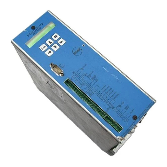
FDS
FREQUENCY INVERTER
POSIDRIVE
®
FDS 4000
Installation and Commissioning Instructions
It is essential to read and comply with these
instructions prior to installation and
commissioning.
M A N A G E M E N T S Y S T E M
certified by DQS according to
DIN EN ISO 9001, DIN EN ISO 14001
Reg-No. 000780 UM/QM
POSITIONING CONTROL
VECTOR CONTROL
SYNCHRONOUS
OPERATION
TECHNOLOGY
SV. 4.5
07/2003
Related Manuals for Stober FDS 4000
Summary of Contents for Stober FDS 4000
System 19 Technical Specifications 10. Electrical Installation PHYSICAL INSTALLATION Dimension in mm BG I BG II BG III Height Width Frequency inverter, base plate Depth Vertical 282,5 282,5 392,5 Base plate, above mounting holes below Min. Connection Assignment — Control Portion Function Circuiting Term. Inverter Exchange, Compatibility 7. Commissioning Status If no temperature sensor exists, X2. The internal 12 V voltage on X1. This requires a jumper between X1. Default display is 0%. When 100% is reached, remove enable. The release time F06 and application L-level signal. Special functions Parameter record selection Motor potentiometer The FDS inverter supports two separate parameter records. Is the grounding External connection okay? Are there any other wiring errors? A motor with a built-on incremental encoder or SSI encoder is the prerequisite for precise and reproducible positioning. I31 is used to determine the search direction when reference point traversing is started. Positioning Control Example 2: Three fixed positions are always traversed in the Tips: same order pick and place. Positioning Control Example 4: A rotary attachment is to be positioned Solution: The first part of the movement is handled by continuously and without drift in 60° increments. The following tasks are supported. Gearbox tension reduction Torque limit 11. There are several ways to wire the master-slave connection. The angle of deviation is reset when: of master and slave when the power goes off. Description Save parameter: 0: inactive; 1: The parameters of both parameter records are saved in non-volatile memory. Saving is triggered when the value changes from 0 to 1. Description Select parameter set: Two parameter records are available. These can be selected via the binary inputs or directly via A41. The selected parameter record does not become active until the enable has been removed and after a maximum of 300 msec have passed. Description Motor-type: Motor selection from the motor data base. Description Control mode: Specifies the type of motor control. Motor voltage is briefly reduced to prevent overcurrent switchoff. Description M-Max 1: Maximum torque in % of nominal motor torque. Description Operating range n-Min: Parameters C41 to C46 can be used to specify an operating area. All area monitoring procedures are performed at the same time. Is only used for specification of reference value via terminal strip X1 and motor potentiometer. Corresponds to a reverse in direction of rotation. Not related to the selected reference value. Device utilization: Indicates the current load of the inverter in %. Description Option-board: Indication of the option board detected during initialization. See F01, F02 and F06 and F07. Description 10: reference value; Ref. This can be used to generate the standard deviation Continuation from two analog inputs. Description 3: reference value-select 2; See above. Description 26: disable PID-controller; PID controller on AE2 is disabled and the integrator is reset. The drive can be moved Continuation as desired via analog input AE1, for example. The total gain of the control loop is also affected by F22 AE2 gain in addition to G01. The increments of the incremental encoders are specified with F36 and H22. Offset of the static friction i. Value is converted to the motor shaft. Description Parameter record switchover cannot be used for the parameters of groups I, J and L. To save memory space, they are only present once. Position range: 0: limited;… Indication of the unit of measure defined as desired by the user with FDS Tool. Up to 4 characters can be used. For example, this can be used to set the actual position to zero at all Continuation times enable must be active. Effective only when axis is referenced. Manual-traversing and continuous process blocks are stopped at the software stops. Command Process Blocks Para. Description Process block number: Selection of the process block which can be started at all times with posi. Command Process Blocks Para. Switches For description, see chap. Description S1-position: Position of switching point S1. Value range in I05: -31 bits to 0 to 31 bits S1-method: Reference of position N10 0: absolute;… Option Boards ANTRIEBSTECHNIK 14. Press the clip together, and push it into the slit on the housing. Result Table Result Table The result of actions e. Possible results are listed below. Operating States Operating States The operating state is indicated in the display and can be queried under E80 during fieldbus access. If installed when the fault occurs, the Parabox is written automatically. If installed when the fault occurs, the Parabox is written automatically. Block Circuit Diagram Synchronous Running AE2 AE1 extern speed feed forward 14:synchron ref. Block Circuit diagram Reference Value Processing… Parameter Table Parameter Entry Parameter Entry Parameter Entry A.. Inverter Ki-IQ moment D52 Fix ref. Machine Variant-number BE9-function Position range… Parameter Table Parameter Entry Process Block 1 — 8 Block 1 Block 2 Block 3 Block 4 Block 5 Block 6 Block 7 Block 8 J10 to J18 J20 to J28 J30 to J38… Designation Remark Connector for DC link only FDS Chap. Designation Remark 40021 CAN bus, Kommubox CAN bus documentations: Interface module for CAN bus with CANopen profile Publ. Designation Remark 42224 External operator, CONTROLBOX Operating unit for parameterisation and operation of the converters. Connecting lead 2 m is included in the scope of supply. The Drive for Your Automation Presented by: STÖBER ANTRIEBSTECHNIK GmbH + Co.
®
POSIDRIVE
FDS 4000
13. Parameter Description
C.. Machine
Para. No. Description
M-Max 1: Maximum torque in % of nominal motor torque. The active torque limit can be further reduced with an
C03
analog input (see F25=2). If the maximum torque is exceeded, the controller responds with the message
«47:drive overload.» See also remarks for C04.
Value range in %: 0 to 150 to 400%*
M-Max 2: Additional torque limit. You can switch between C03 and C04 with a binary input (F3..=10:torque
C04
select) or automatically when startup mode= cycle characteristic (C20=2). See chap. 9.2.
Remarks: Since C04 is always active for a quick stop, C04 ≥ C03 should usually apply!
Value range in %: 0 to 150 to 400%*
Skip speed 1: Only if C60≠2 (run mode≠position). Prevents prolonged use of the drive in a frequency range
C10
which produces mechanical resonance. The drive goes through the entered speeds and tolerance band of
±0.4 Hz with the decel-quick ramp (D81). The four «skip speeds» can be specified next to each other.
Value range in rpm: 0 to 12000
Skip speed 2: See C10.
C11
Value range in rpm: 0 to 12000
Skip speed 3: See C10.
C12
Value range in rpm: 0 to 12000
Skip speed 4: See C10.
C13
Value range in rpm: 0 to 12000
Startup mode: Determines the startup behavior of the drive
C20•
0: standard; Default setting. Separate from control mode (B20).
1: load start; Only if B20=1 (sensorless VC). For machines with increased breakaway torque. The motor torque
is increased to M-load start (C21) during the time t-load start (C22). After expiration of this time, the inverter
uses the standard ramp again.
2: cycle characteristic; Effective separately from the control mode (B20).
— Automatic switch between the specified torque limits M-Max 1 (C03) and M-Max 2 (C04). M-Max 1 applies
during constant travel. M-Max 2 applies during the acceleration phase.
— If B20=1 (sensorless vector control), a torque precontrol procedure is performed (i.e., the inverter calculates
the required torque from the motor type specified (B00) and the ratio of load/motor inertia (C30). This
calculated torque is then given to the drive.
3: capturing; Only if B20=1. A rotating motor is connected to the inverter. The inverter determines the actual
speed of the motor, synchronizes itself, and specifies the appropriate reference value.
M-load start: Only if C20=1 (load start). Specification of the torque for the load start.
C21
Value range in %: 0 to 100 to 400
t-load start: Only if C20=1. Time for the load start with the torque defined in C21.
C22
Value range in sec: 0 to 5 to 9.9
J-mach/J-motor: Ratio of the inertia of load to motor. This factor is effective for all control modes and is
C30
important for optimization between inverter and motor (i.e., dynamics). Entry is not mandatory.
Remarks: In winding mode, the effective inertia torque is calculated for C30 ≥ 1.5 to the fourth power with the winding
diameter for compensation of the acceleration torque. The following applies: J (D-Min) = 1.5 * J-motor, J (D-Max)= C30 *
J-motor. The torque supplied by the drive is increased so that traction remains constant and extra torque is available for
acceleration.
Value range: 0 to 1000
n-controller Kp: Only if B20=2 (vector control with feedback).
C31
Proportional gain of the speed controller. The internal gain also
depends on the number of poles (default setting is for 4 poles).
Remarks: In winding mode (G10>0), the Kp gain with the winding diameter is
quadratically reduced from C31 for D-Max down to C31*C35 for D-Min.
Value range in %: 0 to 60 to 400
n-controller Ki: Only if B20=2. Integral gain of the speed controller. Reduce C32 when overswinging occurs in
C32
the target position.
Value range in %: 0 to 30 to 400
n-control. Kp standstill:
C35
Without winders: C31 and C32 are multiplied by C35 as soon as the motor speed drops below C40.
With winders: The formulas described under C31 and C32 apply.
Value range in %: 5 to 100
n-window: If F00=3 (relay 2 as signal relay for «3:reference value-reached») or F00=2 (relay 2 as signal contact
C40
for speed «2:standstill»), the reference value is considered achieved in a window of reference value ±C40, and
relay 2 closes. A halting brake is not activated as long as [n] > C40.
Value range in rpm: 0 to 30 to 300
P
Speed depends on pole number B10; f
•
The power pack must be turned off before these parameters can be changed.
Italics These parameters are sometimes not shown depending on which parameters are set.
1)
See result table in chap. 15.
Parameters which are included in the normal menu scope (A10=0). For other parameters, select A10=1:extended or A10=2:service.
Parameters marked with a «
* Value is limited by the maximum inverter current.
* Value is limited by the maximum inverter current.
P
P
(
depends on poles B10; f
P
P
P
P
= 400 Hz. With a 4-pole motor, this is 12000 rpm at 400 Hz.
max
√
» can be parameterized separately from each other in parameter record 1 and 2.
= 400 Hz)
max
n-controller Kp
n-post
ramp
n-motor
2) Only available when D90≠1
STÖBER
ANTRIEBSTECHNIK
√
√
√
√
√
√
√
√
√
√
√
n-contr. Ki
M-ref.val.
√
√
√
31
Показаны 1 — 13 из 13 товаров
Показаны 1 — 13 из 13 товаров
Доставка stober posidrive 4000 fds4000
Оформив покупку у нас Вы 100% заберете свой заказанный товар в самые короткие сроки !
Ведь купить товар из-за рубежа не так просто, а мы с легкостью организуем почтовую пересылку по всей России и СНГ (доставка организована в Казахстан,Украину,Беларусию и т.д.) .
На этой странице указаны особенности и техническая спецификация товара, доставка бесплатна и цена (указана в рублях) на все товары на нашем сайте окончательна (доплачивать при получении посылки не нужно).
Страхование всех посылок заказанных у нас является гарантией получения товара , а грамотные специалисты помогут Вам купить stober posidrive 4000 fds4000 без особых проблем и получить только радость от покупки .
Вы также можете воспользоваться нашим онлайн-каталогом для поиска других товаров (более 300 миллионов товаров со всего мира ) , которые мы тоже можем заказать для Вас . Уже более 60 000 человек оценили убоство работы с нашей компанией.
Купить stober posidrive 4000 fds4000
Если Вы ищите сайт, где можно найти много разных stober posidrive 4000 fds4000 то Вы попали по адресу! У нас можно купить с доставкой по России и СНГ (мы осуществляем доставку в Беларусию,Украину,Казахстан и т.д.) .
Все посылки заказываемые через нашу компанию застрахованы и это 100% гарантия получения товара . Квалифицированная служба поддержки поможет Вам, проконсультирует по потребительским свойствам , что позволит получить только радость и хорошие эмоции от покупки.
Если Вы пролистаете страницу Выше, то найдете таблицу,где указаны все технические характеристики и особенности.
Доставка в Ваш город бесплатна, а ценовое предложение указанно в рублях (на все товары в нашем огромном онлайн-каталоге) — окончательна(доплата при получении заказа на почте не потребуется).
Мы занимаемся доставкой товаров из-за рубежа уже более 10 лет , что позволяет со 100% гарантией утверждать ,
что мы купим stober posidrive 4000 fds4000 и сделаем его пересылку до Вас быстрой и безопасной, без затягивания сроков и любых проблем.
Воспользуйтесь нашим онлайн-каталогом, чтобы найти другие товары т.к. в них находится больше чем 300 000 000 лотов со всего мира,
которые мы тоже можем заказать для Вас.
Гарантия на stober posidrive 4000 fds4000
Купив у нас Вы гарантированно получите свою покупку как указано в описании и в самые короткие сроки! Мы организуем доставку по всей России и СНГ ( доставка в Беларусию,Украину,Казахстан и т.д.) .
Вы также можете воспользоваться нашим каталогом для поиска других товаров ( более 300 миллионов товаров со всего мира ) , которые мы тоже можем заказать для Вас.
Мы предлагаем супер-цену на stober posidrive 4000 fds4000, а также Вы бесплатно получаете возможность воспользоваться нашей расширенной программой защиты покупателя и бесплатной доставкой. Цена указана в рублях на все товары в этой категории окончательна .
Все заказы застрахованы на 5 000 000 (пять миллионов рублей) в СК «Гелиос».
Случайный отзыв о нашей работе
Здравствуйте. Могу оставить только положительный отзыв. Заказывала куклу Барби. Несмотря на санкции и ожидание 2 месяца посылку получила. Операторы отвечали быстро и вежливо. Кампания уложилась в гарантийный срок доставки. Если честно, думала, что заказ не смогут выполнить, и я потеряю деньги — но все получилась. Спасибо.. Автор Юлия Воронцова. Дата 2022-06-10. Населенный пункт: г Уфа