- Manuals
- Brands
- Kyocera Mita Manuals
- All in One Printer
- KM-1500
- Operation manual
-
Contents
-
Table of Contents
-
Troubleshooting
-
Bookmarks
Quick Links
1500
KM-
Please read the Operation Guide before using the copier
Keep it close to the copier for easy reference
Related Manuals for Kyocera Mita KM-1500
Summary of Contents for Kyocera Mita KM-1500
-
Page 1
1500 Please read the Operation Guide before using the copier Keep it close to the copier for easy reference… -
Page 2
All rights reserved. No part of this material may be reproduced or transmitted in any form or by any means, electronic or mechanical, including photocopying, recording or by any information storage and retrieval system, without permission in writing from the Publisher. Legal Restriction On Copying •… -
Page 3
Introduction to this Operation Guide Symbols in this guide The explanations contained in this operation guide have been This Operation Guide contains certain symbols to indicate points of separated into different sections in order to allow even those using caution and additional information that is important for you to a copier for the first time to use this machine efficiently, properly know. -
Page 4: Table Of Contents
CONTENTS Section 7 TROUBLESHOOTING ……7-1 Energy Star Program …………..iii Please read this Operation Guide before using the copier. Keep it If one of the following indications is displayed ……7-1 close to the copier for easy reference……….iv If paper jams ………………7-3 Misfeed location indicators ………….
-
Page 5: Energy Star Program
Energy Star Program We have determined as a participating company in the International Energy Star Program that this product is compliant with the standards laid out in the International Energy Star Program. About the International Energy Star Program International Energy Star Program has as its basic goals the promotion of efficient energy use and the reduction of the environmental pollution that accompanies energy consumption by promoting the manufacture and sale of products that fulfill…
-
Page 6: Please Read This Operation Guide Before Using The Copier. Keep It Close To The Copier For Easy Reference
Please read this Operation Guide before using the copier. Keep it close to the copier for easy reference. Please read this Operation Guide before using the copier. Keep it close to the copier for easy reference. The sections of this guide and parts of the copier marked with symbols are safety warnings meant to protect the user, other individuals and surrounding objects, and ensure correct and safe usage of the copier.
-
Page 7: Important! Please Read First
Section 1 IMPORTANT! PLEASE READ FIRST. CAUTION LABELS Caution labels have been attached to the copier at the following locations for safety purposes. BE SUFFICIENTLY CAREFUL to avoid fire or electric shock when removing a paper jam or when replacing toner.
-
Page 8: Installation Precautions
INSTALLATION PRECAUTIONS Environment During copying, some ozone is released, but the amount does not cause any ill effect to one’s health. If, CAUTION however, the copier is used over a long period of time in a poorly ventilated room or when making an extremely large number of copies, the smell may become unpleasant.
-
Page 9: Precautions For Use
PRECAUTIONS FOR USE CAUTION Cautions when using the copier WARNING DO NOT pull the power cord when removing it from the outlet. If the power cord is pulled, the wires may become broken and there is a DO NOT place metallic objects or containers danger of fire or electrical shock.
-
Page 10: Cautions When Handling Consumables
Cautions when handling Other precautions consumables DO NOT place heavy objects on the copier or cause CAUTION other damage to the copier. DO NOT open the upper front cover, turn off the power switch, or pull out the power plug during copying.
-
Page 11: Laser Safety
Laser Safety Laser radiation could be hazardous to the human body. For this reason, laser radiation emitted inside this machine is hermetically sealed within the protective housing and external cover. In the normal operation of the product by user, no radiation can leak from the machine. This machine is classified as Class 1 laser product under IEC 60825.
-
Page 12
CAUTION! The power plug is the main isolation device! Other switches on the equipment are only functional switches and are not suitable for isolating the equipment from the power source. VORSICHT! Der Netzstecker ist die Hauptisoliervorrichtung! Die anderen Schalter auf dem Gerät sind nur Funktionsschalter und können nicht verwendet werden, um den Stromfluß… -
Page 13
DECLARATION OF CONFORMITY 89/336/EEC, 73/23/EEC and 93/68/EEC We declare under our sole responsibility that the product to which this declaration relates is in conformity with the following specifications. Limits and methods of measurement for immunity characteristics of information technology equipment EN55024 Limits and methods of measurement for radio interference characteristics of information technology equipment… -
Page 15: Names Of Parts
Section 2 NAMES OF PARTS Main Body (11) (10) (1) Original cover (8) Toner container (Open/close this cover when you are setting the original on the (9) Lock lever platen.) (Operate this lever when you need to replace the toner (2) Platen container.) (Set originals here for copying.
-
Page 16
Section 2 NAMES OF PARTS (16) (15) (14) (13) (13) (19) (19) (12) (17) (18) (12) Drawer (This drawer has a storage capacity of 250 sheets of standard copy paper (80 g/m²).) (13) Paper width guides (Adjust these guides to fit the width of the paper that is to be loaded in the drawer.) (14) Paper stopper (Adjust this stopper to fit the length of the paper that is to be… -
Page 17
Section 2 NAMES OF PARTS (23) (24) (21) (20) (22) (20) Power switch (23) Document Processor connector (Turn this switch ON ( | ) before copying.) (Attach the connection cable here when installing the optional (21) Face-up tray Document Processor.) (Finished copies can be ejected and stored face-up on this tray. -
Page 18: Operation Panel
Section 2 NAMES OF PARTS Operation panel (24) (23) (22) (19) (18) (21) (20) (16) (12) (17) (13) (11) (10) (14) (15) (1) Start key & indicator (8) Number of Copies / Zoom(-) key (Press this key when you want to start copying. Copying will (Press this key when you want to lower the number of copies begin immediately if you press this key when the indicator is to be made, as well as to decrease the currently selected copy…
-
Page 19: Auto Clear Function
Section 2 NAMES OF PARTS Initial mode (15) Program key & indicator (the state that the copier enters at the end of (Press this key when you want to copy with the Program warm-up or when the Reset/Power key is pressed) function.
-
Page 20
Section 2 NAMES OF PARTS… -
Page 21: Section 3 Preparations
Section 3 PREPARATIONS Loading paper Loading paper into a drawer Copy paper can either be loaded into the drawer(s) or set on the multi-bypass tray. Standard copy paper (60 g/m² – 90 g/m²), thick paper (90 g/m² – 105 g/m²), recycled paper, or color paper can be loaded into each Note when adding paper drawer.
-
Page 22
Section 3 PREPARATIONS Pull the drawer all the way out of the copier. Set the paper in the drawer so that the leading edge is aligned against the paper stopper, but making sure that none of the paper gets caught on the overhanging tabs. IMPORTANT! When pulling the drawer out of the copier, be sure to IMPORTANT! -
Page 23
Section 3 PREPARATIONS Adjusting the paper stopper for Folio or Push the drawer securely all the way back into the copier until it stops. Oficio II size paper Perform the following procedure to adjust the paper stopper when you want to load Folio or Oficio II size paper into the drawer. Remove the stopper extension lock from the paper stopper. -
Page 24: Selecting The Paper Size
Section 3 PREPARATIONS Selecting the paper size Press down on the stopper extension lock and slide the paper stopper towards the rear of the drawer to set the lock Perform the following procedure to use the operation panel and into place. The paper stopper is now in position for Folio select the size of paper that is loaded in the drawer.
-
Page 25: Setting Paper On The Multi-Bypass Tray
Section 3 PREPARATIONS Setting paper on the multi-bypass tray Press the Number of Copies / Zoom(+) or Number of Copies / Zoom(-) key to select the appropriate paper size. The displayed code numbers refer to the available paper Standard copy paper (60 g/m² – 90 g/m²), thick paper (90 g/m² – sizes as explained in the following table.
-
Page 26
Section 3 PREPARATIONS Open the multi-bypass tray towards you until you hear it Slide the paper all the way in, along the insert guides, as click into place. far as it will go. Pull out the multi-bypass extension and then flip it open. IMPORTANT! •… -
Page 27
Section 3 PREPARATIONS Selecting the paper size Press the Number of Copies / Zoom(+) or Number of Copies / Zoom(-) key to select the appropriate paper size. Perform the following procedure to use the operation panel and The displayed code numbers refer to the available paper select the size of paper that is set on the multi-bypass tray. -
Page 28
Section 3 PREPARATIONS Selecting the paper size (temporary setting) Press the Recall%/Enter key. The copier will return to a copy-ready state. Press the Paper Select key until the multi-bypass tray indicator is lit. Press the Number of Copies / Zoom(+) or Number of Copies / Zoom(-) key to select the appropriate paper size. -
Page 29: Thick Paper Mode
Section 3 PREPARATIONS Thick Paper mode Perform the following procedure to select the Thick Paper mode when copying onto thick copy paper (90 g/m² – 163 g/m²). When this mode is selected, copying will be carried out at a higher fixing temperature and the copy speed will be lowered in order to ensure efficient fixing of the toner to the copy paper.
-
Page 30: Attaching The Face-Up Tray
Section 3 PREPARATIONS Attaching the face-up tray When copying onto special paper, such as thick paper (90 g/m² – Perform the standard copying procedure. Finished copies 163 g/m²) and OHP transparencies, ALWAYS use the face-up tray. will be ejected onto the face-up tray. The face-up tray has a storage capacity of 30 sheets of standard copy paper (80 g/m²) but only 1 sheet of special paper should be stored there at one time.
-
Page 31: Basic Operation
Section 4 BASIC OPERATION Basic copying procedure Warm-up Selecting the image quality Turn the power switch ON ( | ). At the end of warm-up, the The image quality mode can be selected according to the Start indicator will light. type of original.
-
Page 32
Section 4 BASIC OPERATION Adjusting the copy exposure Setting an original The copy exposure can be manually adjusted in all of the Open the original cover and set the original that you want image quality modes, except for the Auto Exposure to copy face-down onto the platen. -
Page 33
Section 4 BASIC OPERATION At the end of copying Finished copies will be ejected onto the copy storage table. NOTE The copy storage table has a storage capacity of 150 sheets of standard copy paper (80 g/m²). CAUTION If the copier will not be used for a short period of time (overnight, etc.), turn the power switch OFF ( ). -
Page 34: Making Enlarged And Reduced Copies
Section 4 BASIC OPERATION Making enlarged and reduced copies Zoom mode Press the Recall%/Enter key. The new magnification ratio will be registered and the copy quantity/magnification display will return to showing the number of copies to be With this mode, the magnification ratio can be set to any 1% made.
-
Page 35: Preset Zoom Mode
Section 4 BASIC OPERATION Preset Zoom mode Press the Recall%/Enter key. The new magnification ratio will be registered and the copy quantity/magnification display will return to showing the number of copies to be With this mode, the magnification ratio can be set to one of the made.
-
Page 36
Section 4 BASIC OPERATION… -
Page 37: Copy Functions
Section 5 COPY FUNCTIONS Layout modes 2-in-1 With this mode, the images from either 2 or 4 originals can be reduced and then combined onto a single copy. In addition, the borderline of each original can also be marked with a solid or Use this mode when you want to copy two originals onto each sheet dotted line.
-
Page 38
Section 5 COPY FUNCTIONS Caution on setting the originals The following illustrations indicate how the orientation of the original will affect the resulting copies. <When setting the originals on the platen> NOTE Make sure the originals are set so that the first page is scanned first. -
Page 39
Section 5 COPY FUNCTIONS <When setting the originals in the Document Processor> NOTE Make sure the originals are set so that the first page is scanned first. -
Page 40
Section 5 COPY FUNCTIONS Press the 2in1/4in1 key until the 2in1 indicator lights. Once you have finished scanning all of the originals, press the Recall%/Enter key or the 2in1/4in1 key. Copying will start. NOTE It is possible for you to change the type of borderline. (See “Selecting the borderline”… -
Page 41: In-1
Section 5 COPY FUNCTIONS 4-in-1 <When setting the originals in the Document Processor> Use this mode when you want to copy four originals onto each sheet of copy paper. Original Copy Caution on setting the originals Be sure to set the originals as shown in the following illustrations. <When setting the originals on the platen>…
-
Page 42: Selecting The Borderline
Section 5 COPY FUNCTIONS Selecting the borderline Press the Start key. Scanning of the first original will start. Perform the following procedure when you want to change the type of borderline. NOTE If the optional Document Processor is installed on your copier, all of the originals set there will be scanned and the copy operation will start.
-
Page 43: Selecting The Order Of 4-In-1 Layout
Section 5 COPY FUNCTIONS Selecting the order of 4-in-1 layout Press the Number of Copies / Zoom(+) or the Number of Copies / Zoom(-) key to select the desired borderline. The displayed code numbers refer to the available Perform the following procedure if you want to select the order in borderline types as explained in the following table.
-
Page 44
Section 5 COPY FUNCTIONS Press the Number of Copies / Zoom(+) or the Number of Copies / Zoom(-) key until the number that corresponds to desired layout order (1 – 4) is shown. The displayed code numbers refer to the available layout orders as explained in the following table. -
Page 45: Sort Mode
Section 5 COPY FUNCTIONS Sort mode Multiple originals can be scanned into memory in a single Once scanning of the first original is completed, “1-” (the operation and then the desired number of copy sets created. number of originals already scanned) will be shown. Set the next original and press the Start key.
-
Page 46
Section 5 COPY FUNCTIONS 5-10… -
Page 47: Copy Default Settings
Section 6 COPY DEFAULT SETTINGS Available default items The state that the copier enters at the end of warm-up or when the Reset/Power key is pressed is called the “initial mode”. The modes, functions and other settings that are automatically pre-set for use in the initial mode are called “default settings”. These default settings can be changed as desired to suit your copying needs.
-
Page 48
Section 6 COPY DEFAULT SETTINGS Item Reference Default Description Available settings number page Multi-Bypass Tray Paper Registers the size of paper that is to be set on -A4: A4 Size the multi-bypass tray. -A5: A5 * The “XXX” shown here refers to the actual -A6: A6 width of the paper as registered under the -Fo: Folio… -
Page 49
Section 6 COPY DEFAULT SETTINGS Item Reference Default Description Available settings number page Paper Feeder Skewed Adjusts for off-center printing. -1.0 – 3.0 (mm) Feed Adjustment (option) * If the optional Paper Feeder is not installed (Adjustment is complete on your copier, this default setting will not at the time of purchase.) appear. -
Page 50: Section 6 Copy Default Settings
Section 6 COPY DEFAULT SETTINGS Accessing and changing the default settings Press the Recall%/Enter key. NOTE If you selected default items “F01” or “F32”: The If you want to access the “F30” default item (Document corresponding list/report will be printed out. Proceed to Processor Skewed Feed Adjustment), proceed directly to step 4.
-
Page 51
Section 6 COPY DEFAULT SETTINGS Sample User Copy Setting List Press the Number of Copies / Zoom(+) or the Number of Copies / Zoom(-) key to select either ON or OFF. (F21 and F25) Press the Recall%/Enter key. The operation panel will return to the display in step 2. -
Page 52
Section 6 COPY DEFAULT SETTINGS Press the Recall%/Enter key. The operation panel will If the result is as shown in example (1), increase the return to the display in step 2. Once you are finished setting. If the result is as shown in example (2), decrease accessing default items, proceed to step 17. -
Page 53
Section 6 COPY DEFAULT SETTINGS The selected setting will change each time you press the Prior to performing the adjustment procedure, it is Number of Copies / Zoom(+) or the Number of Copies / necessary to use the Document Processor to make copies in Zoom(-) key. -
Page 54
Section 6 COPY DEFAULT SETTINGS If the result is as shown in example (1), increase the Prior to performing the adjustment procedure, it is setting. If the result is as shown in example (2), decrease necessary to use the Document Processor to make copies in the setting. -
Page 55
Section 6 COPY DEFAULT SETTINGS Arrange the original and copy one on top of the other to verify the direction and amount of the shift. If the result is as shown in example (1), increase the setting. If the result is as shown in example (2), decrease the setting. -
Page 56: Checking The Total Copy Count And Printing Out A Report
Section 6 COPY DEFAULT SETTINGS Checking the total copy count and printing out a report It is possible to use the operation panel to check the total number of Sample Total Count Report copies made. It is also possible to print out that information in the form of a report.
-
Page 57: Troubleshooting
Section 7 TROUBLESHOOTING If one of the following indications is displayed When any of the following indications appears on the copy quantity/magnification display, perform the corresponding procedure. Reference Indication Procedure Page “E07” appears on the copy quantity/ The size of paper registered in the default settings is different than the magnification display size of the paper actually used.
-
Page 58: Section 7 Troubleshooting
Section 7 TROUBLESHOOTING Reference Indication Procedure Page “E72” appears on the copy quantity/ Originals for another job were set in the optional Document Processor — magnification display during copying from the platen in the 2-in-1 or 4-in-1 layout mode or in the Sort mode.
-
Page 59: If Paper Jams
Section 7 TROUBLESHOOTING If paper jams If a paper jam occurs, copying will stop. In this case, an indication about the jam will appear on the operation panel. Leave the power switch ON ( | ) and refer to “Removal procedures” on page 7-4 to remove the jammed paper. Misfeed location indicators Cautions WARNING…
-
Page 60: Removal Procedures
Section 7 TROUBLESHOOTING Removal procedures If the leading edge of the jammed paper is visible, pull it out towards you. If the paper is not visible at all, perform the “Paper jam in a drawer” procedure. Paper jam inside the copier If the paper has been fed to the rear of the copier but the leading edge is not visible, perform the “Paper jam in the paper eject section”…
-
Page 61
Section 7 TROUBLESHOOTING Paper jam in a drawer Open and then close the upper front cover. The error indications will go out. Pull out the drawer that is currently being used. Remove the jammed paper. NOTE If a paper jam occurs in the optional Paper Feeder, the procedure to remove jammed paper is the same as with the included drawer. -
Page 62
Section 7 TROUBLESHOOTING Paper jam in the paper eject section Open and then close the upper front cover. The error indications will go out. Open the face-up tray. Remove the jammed paper. CAUTION The copier’s fixing unit is extremely hot. Take sufficient care when working in this area, as there is a danger of getting burned. -
Page 63
Section 7 TROUBLESHOOTING Paper jam in the multi-bypass tray Original jam in the optional Document Processor Remove all of the paper remaining on the multi-bypass tray. Remove all of the originals remaining on the original table. Open and then close the upper front cover. The error Open the left cover to the Document Processor. -
Page 64
Section 7 TROUBLESHOOTING Remove the jammed original. Close the Document Processor. Reset the originals. -
Page 65: If Other Trouble Occurs
Section 7 TROUBLESHOOTING If other trouble occurs If trouble occurs with your copier, carry out the applicable checkpoints and procedures indicated on the following pages. If the trouble persists, contact your service representative or authorized service center. Reference Trouble Checkpoint Procedure Page Nothing lights on the…
-
Page 66
Section 7 TROUBLESHOOTING Reference Trouble Checkpoint Procedure Page Black or white vertical bands Is the charger cleaner in its home position Remove the Process Unit and return the appear on the copies. (marked “CLEANER HOME POSITION”)? charger cleaner to its home position. If you are using the optional Document Clean the slit glass. -
Page 67: Maintenance And Operation Information
Section 8 MAINTENANCE AND OPERATION INFORMATION Cleaning the copier If the optional Document Processor is installed on your copier, lift open the Document Processor and wipe the gray portion, as shown CAUTION in the illustration, with a soft cloth dampened with alcohol or mild detergent.
-
Page 68: Replacing The Toner Container
Section 8 MAINTENANCE AND OPERATION INFORMATION Replacing the toner container When toner runs low, the Add Toner indicator will light. If you Open the upper front cover. continue to make copies while the Add Toner indicator is lit, “E33” will appear on the copy quantity/magnification display and the copier will stop.
-
Page 69
Section 8 MAINTENANCE AND OPERATION INFORMATION Pull the lock lever towards you into its release position Shake the new toner container horizontally 5 or 6 times to (marked “UNLOCK”), then pull the toner container release ensure that the toner is evenly distributed inside. lever to the right as indicated by the arrow ( ) in the illustration. -
Page 70: Cleaning The Charger And The Registration Roller
Section 8 MAINTENANCE AND OPERATION INFORMATION Cleaning the charger and the registration roller Hold the Process Unit stable and push on the areas marked “PUSH HERE” on the toner container, until the container Perform the following cleaning operation whenever you replace the clicks into place.
-
Page 71
Section 8 MAINTENANCE AND OPERATION INFORMATION Close the front cover. Close the upper front cover. After use, ALWAYS dispose of the toner container in accordance with Federal, State and Local rules and regulations. -
Page 72: Specifications
Section 8 MAINTENANCE AND OPERATION INFORMATION Specifications Main Body Type……………..Desktop Original table …………..Fixed type Copying system …………..Indirect electrostatic system Acceptable originals …………Sheets of paper, books and 3-dimensional objects (Maximum size: 8 » × 14″ (Legal) / Folio) Copy sizes ……………Drawer: 8 «…
-
Page 73: Document Processor (Option)
Section 8 MAINTENANCE AND OPERATION INFORMATION Document Processor (option) Original feed system …………Automatic feeding Acceptable originals…………Sheets of paper Original sizes …………..Max.: 8 » × 14″ (Legal) and Folio Min.: 5 » × 8 » (Statement) and A5R Original paper weight…………
-
Page 74: Environmental Specifications
Section 8 MAINTENANCE AND OPERATION INFORMATION Environmental Specifications • Recovery time from the Low Power mode….10 seconds • Transition time to the Low Power mode (at time of purchase) ………..15 minutes • Transition time to the Off and Sleep modes (at time of purchase) ………..30 minutes Duplex (2-sided) copying •…
-
Page 75
For best copy results and machine performance, we recommend that you use only KYOCERA MITA original supplies for your KYOCERA MITA copier. -
Page 76
KYOCERA MITA DEUTSCHLAND GMBH KYOCERA MITA GMBH AUSTRIA KYOCERA MITA TAIWAN CORPORATION KYOCERA MITA SVENSKA AB KYOCERA MITA KYOCERA MITA NORGE CORPORATION ©2003 KYOCERA MITA CORPORATION is a trademark of Kyocera Corporation 2003. 3 is a registered trademark of KYOCERA MITA CORPORATION 2DC80030A…
-
Contents
-
Table of Contents
-
Troubleshooting
-
Bookmarks
Quick Links
KM-1500
SERVICE
MANUAL
Published in Mar. ’04
842DC113
Revision 3
Related Manuals for Kyocera KM-1500
Summary of Contents for Kyocera KM-1500
-
Page 1: Service Manual
KM-1500 SERVICE MANUAL Published in Mar. ’04 842DC113 Revision 3…
-
Page 2
CAUTION Danger of explosion if battery is incorrectly replaced. Replace only with the same or equivalent type recommended by the manufacturer. Dispose of used batteries according to the manufacturer’s instructions. CAUTION Double-pole/neutral fusing. -
Page 3: Safety Precautions
Safety precautions This booklet provides safety warnings and precautions for our service personnel to ensure the safety of their customers, their machines as well as themselves during maintenance activities. Service personnel are advised to read this booklet carefully to familiarize themselves with the warnings and precautions described here before engaging in maintenance activities.
-
Page 4
Safety warnings and precautions Various symbols are used to protect our service personnel and customers from physical danger and to prevent damage to their property. These symbols are described below: DANGER: High risk of serious bodily injury or death may result from insufficient attention to or incorrect compliance with warning messages using this symbol. -
Page 5: Installation Precautions
1. Installation Precautions WARNING • Do not use a power supply with a voltage other than that specified. Avoid multiple connections to one outlet: they may cause fire or electric shock. When using an extension cable, always check that it is adequate for the rated current………………… •…
-
Page 6
2. Precautions for Maintenance WARNING • Always remove the power plug from the wall outlet before starting machine disassembly….• Always follow the procedures for maintenance described in the service manual and other related brochures……………………….• Under no circumstances attempt to bypass or disable safety features including safety mechanisms and protective circuits. -
Page 7
• Do not pull on the AC power cord or connector wires on high-voltage components when removing them; always hold the plug itself………………….. • Do not route the power cable where it may be stood on or trapped. If necessary, protect it with a cable cover or other appropriate item. -
Page 8: Specifications
2DC-2 CONTENTS 1-1 Specifications 1-1-1 Specifications ……………………….1-1-1 1-1-2 Name of parts ……………………….1-1-2 (1) Copier ……………………….. 1-1-2 (2) Operation panel ……………………..1-1-3 1-2 Handling Precautions 1-2-1 Drum …………………………1-2-1 1-2-2 Installation environment ……………………1-2-1 1-3 Installation 1-3-1 Unpacking and installation ……………………1-3-1 (1) Installation procedure ……………………
-
Page 9: Table Of Contents
2DC-2 (8) The eraser lamp does not turn on………………..1-5-21 (9) The exposure lamp does not turn on……………….. 1-5-21 (10) The exposure lamp does not turn off……………….. 1-5-21 (11) The heater lamp does not turn on………………..1-5-21 (12) The heater lamp does not turn off.
-
Page 10
2DC-2 (6) Adjusting magnification of the scanner in the auxiliary scanning direction ……..1-6-46 (7) Adjusting the scanner leading edge registration …………….1-6-47 (8) Adjusting the scanner center line ………………..1-6-48 (9) Adjusting the margins for scanning an original on the contact glass ……….1-6-49 (10) Adjusting the DP magnification ………………… -
Page 11
2DC-2 1-1-1 Specifications Type ……….Desktop Copying system ……Indirect electrostatic system » × 14″ [legal]) Originals ……… Sheets of paper (Maximum original size: folio/8 Platen: Sheets of paper, books, 3-dimensional objects (Maximum original size: folio/ » × 14″ [legal]) Original feed system …… -
Page 12
2DC-2 1-1-2 Name of parts (1) Copier ‹ › ⁄ ¤ & Figure 1-1-1 Name of parts 1 Original holder # Paper guide 2 Contact glass $ Paper stopper 3 Original size indicator % Stopper extension lock 4 Operation panel ^ Face-down output tray 5 Front top cover &… -
Page 13
2DC-2 (2) Operation panel ⁄ & Figure 1-1-2 1 Start key (Indicator) @ Thick Paper key (Indicator) 2 Reset/Power key # 2in1/4in1 key (Indicators) 3 Stop/Clear key $ Sort key (Indicator) 4 Copy quantity/magnification display % Program key (Indicator) 5 Copy exposure adjustment keys ^ Add toner indicator 6 Image mode selection key &… -
Page 14: Installation Environment
2DC-2 1-2-1 Drum Note the following when handling or storing the drum. • When removing the process unit, never expose the drum surface to strong direct light. • Keep the drum at an ambient temperature between 10°C/50°F and 32.5°C/90.5°F and at a relative humidity not higher than 80% RH.
-
Page 15: Unpacking And Installation
1-3-1 Unpacking and installation (1) Installation procedure Start Unpack. Remove the tapes, pads and sheets. Remove the pin holding scanner unit. Install a toner container. Connect the power cord. Inisializing the copier. Load paper. Make test copies. Completion of the machine installation. 1-3-1…
-
Page 16
Unpack & & Figure 1-3-1 Unpacking 1 Copier ! Front spacer 2 Power cord @ Front pad 3 Toner container # Bottom spacer 4 Operation guide $ Corner support 5 Installation guide % Products cover 6 Cleaning cloth ^ Plastic bag 7 Outer case &… -
Page 17
CAUTIONS • Be sure to hold both the front and rear sides of the copier when carrying it, as shown in the illustration. • Be sure not to pull the cassette out when holding the front of the copier. • Be sure that the original cover is closed whenever transporting the copier. •… -
Page 18
Remove the tapes, pads and sheets. 1. Remove the sheet and the two tapes. Tapes Sheet Figure 1-3-3 2. Open the original cover. Original cover Figure 1-3-4 1-3-4… -
Page 19
3. Remove the nine tapes, the three pads and the sheet. Tapes Tape Tapes Sheet Tapes Figure 1-3-5 4. Pull the cassette out of the copier. Cassette Figure 1-3-6 5. Remove the pad from inside the cassette. Figure 1-3-7 1-3-5… -
Page 20
Remove the pin holding scanner unit. 1. Remove the yellow pin for scanner unit and the paper tag from the left side of the copier. Paper tag Figure 1-3-8 Install a toner container. 1. Open the front top cover and front cover. Front top cover Front cover Figure 1-3-9… -
Page 21
3. Remove the process unit from the copier. CAUTIONS • Place the process unit on a clean, level surface. • Never expose the process unit to any sort of impact or shock. • The drum in the process unit is sensitive to light. Never expose the drum even to normal office lighting (500 lux) for more than five minutes. -
Page 22
6. Shake the toner container horizontally back and forth five or six times so that the toner inside of it becomes evenly distributed. Toner container Figure 1-3-14 7. Remove the orange protective seal. Seal Figure 1-3-15 8. Set the toner container into the process unit. Toner container Process unit Figure 1-3-16… -
Page 23
9. Hold the process unit stable and push in on the areas of the toner container marked “PUSH Toner container HERE” until the container clicks into place in the process unit. Figure 1-3-17 10. Push the lock lever back into its locked position. Lock lever Figure 1-3-18 11. -
Page 24
12. Close the front cover. Front cover Figure 1-3-20 13. Close the front top cover. Front top cover Figure 1-3-21 1-3-10… -
Page 25
2DC-2 Connect the power cord. 1. Connect the power cord. Power cord Figure 1-3-22 Initializing the copier. 1. Turn the power switch to the copier ON ( | ). Power switch Figure 1-3-23 First “900” will appear in the copy quantity/ magnification display on the copier’s operation panel. -
Page 26
Load paper. 1. Pull the cassette out of the copier. Cassette Figure 1-3-25 2. Adjust the paper stopper in the rear portion of the Paper stopper cassette to fit the size of the paper being loaded there by pressing in on the release buttons and sliding the paper stopper to the corresponding paper size. -
Page 27
2DC-2 4) Press down on the stopper extension lock and slide the paper stopper towards the rear of the cassette to set the lock into place. Paper stopper The paper stopper is in position for Folio and Oficio II size paper. Stopper extension lock Figure 1-3-28… -
Page 28
NOTES • DO NOT set more paper than indicated by the lines located on the paper width guides. Paper width guide • Be sure to load paper with the side to be copied onto facing down. Figure 1-3-31 5. Push the cassette securely all the way back into the copier until it stops. -
Page 29
2DC-2 1-3-2 Installing the document processor (option) Procedure 1. Remove all of the components to the document processor from the box. CAUTION Be sure to hold both sides of the document processor when carrying it, as shown in the illustration. Be particularly careful NOT to touch the guide film or the thin white surface indicated by the A in the illustration. -
Page 30
4. Attach the document processor to the copier. CAUTION Be sure that the connection cable does not get caught between the document processor and the copier when attaching the document processor to the copier. Connection cable Figure 1-3-36 5. Gently close the document processor. Document processor Figure 1-3-37… -
Page 31
2DC-2 CAUTION Be sure to tighten the pins securely when connecting the cable. Pins Figure 1-3-39 7. Turn the power switch to the copier back ON ( | ). Warm up will begin. “1” will appear on the operation panel and the Start indicator will light when the copier is in a copy-ready state. -
Page 32
1-3-3 Installing the expanding memory (option) The main board of the copier is equipped with one socket for memory expansion. Expansion memory is available in the form of DIMM (Dual In-line Memory Module). CAUTION Take precautions that no foreign substances such as metal chips or liquid get inside the copier during the installation process. -
Page 33
1-4-1 Maintenance mode The copier is equipped with a maintenance function which can be used to maintain and service the machine. (1) Executing a maintenance item Start Press the stop/clear key, start key and the left copy exposure adjustment key in the order presented and hold them down. -
Page 34
2DC-2 (2) Maintenance mode item list Item Initial Section Maintenance item contents setting* General U000 Outputting an own-status report — U001 Exiting the maintenance mode — U004 Checking the machine number — U005 Copying without paper — U019 Displaying the ROM version —… -
Page 35
2DC-2 Item Initial Section Maintenance item contents setting* Fixing and U161 Setting the fixing control temperature cleaning • Primary stabilization fixing temperature • Secondary stabilization fixing temperature • Copying operation temperature 1 • Copying operation temperature 2 • Number of sheets for fixing control U162 Stabilizing fixing forcibly —… -
Page 36
(3) Contents of maintenance mode items Maintenance Description item No. U000 Outputting an own-status report Description Outputs lists of the current settings of the maintenance items, and paper jam and service call occurrences. Purpose To check the current setting of the maintenance items, or paper jam or service call occurrences. Before initializing the backup RAM, output a list of the current settings of the maintenance items to reenter the settings after initialization or replacement. -
Page 37
2DC-2 Maintenance Description item No. U005 Copying without paper Description Simulates the copy operation without paper feed. Purpose To check the overall operation of the machine. Method 1. Press the start key. A selection item appears. 2. Select the item to be operated using the copy exposure adjustment keys. Display Operation Only the copier operates. -
Page 38
2DC-2 Maintenance Description item No. U020 Initializing all data Description Initializes all the backup RAM on the main board to return to the original settings. U004, however, is not initialized. Purpose Run as needed. Method 1. Press the start key. 2. -
Page 39
2DC-2 Maintenance Description item No. U030 Checking motor operation Description Drives each motor. Purpose To check the operation of each motor. Method 1. Press the start key. A selection item appears. 2. Select the motor to be operated using the copy exposure adjustment keys. When selecting the feed motor, pull out the optional drawer in advance. -
Page 40
Maintenance Description item No. U032 Checking clutch operation Description Turns each clutch on. Purpose To check the operation of each clutch. Method 1. Press the start key. A selection item appears. 2. Select the clutch to be operated using the copy exposure adjustment keys. 3. -
Page 41
2DC-2 Maintenance Description item No. U063 Adjusting the shading position Description Changes the shading position. Purpose Used when white lines continue to appear longitudinally on the image after the shading plate is cleaned. This is due to flaws or stains inside the shading plate. To prevent this problem, the shading position should be changed so that shading is possible without being affected by the flaws or stains. -
Page 42
Maintenance Description item No. U073 Checking scanner operation Description Simulates the scanner operation under arbitrary conditions. Purpose To check scanner operation. Method 1. Press the start key. 2. Select the item to be changed by lighting a copy exposure indicator using the copy exposure adjustment keys. -
Page 43
Maintenance Description item No. U087 Turning the DP scanning position adjust mode on/off Description Turns on or off the DP scanning position adjust mode, in which the DP original scanning position is adjusted automatically by determining the presence or absence of dust on the slit glass. Also changes the reference data for identifying dust. -
Page 44
Maintenance Description item No. U088 Setting the input filter (moiré reduction mode) Description Turns moiré reduction mode on and off by switching the input filter on and off. Purpose Used to prevent regular density unevenness (moiré) on halftone image areas of the copy image in text mode and text and photo mode. -
Page 45
Maintenance Description item No. U091 Checking shading Description Performs scanning under the same conditions as before and after shading is performed, displaying the original scanning values at nine points of the contact glass. Purpose To check the change in original scanning values before and after shading. The results may be used to decide the causes for fixing unevenness (uneven density) of the gray area of an image: either due to optical (shading or CCD) or other problems. -
Page 46
2DC-2 Maintenance Description item No. U091 When scanning is performed before shading, the scan value at the machine center should be slightly different from those at the machine front and rear. When scanning is performed after shading, there should be no difference between respective values. Any differences between the values at machine front and rear indicates that scanner problem causes the fixing unevenness. -
Page 47
2DC-2 Maintenance Description item No. U093 Setting the exposure density gradient Description Changes the exposure density gradient in manual density mode, depending on respective image modes (text, text and photo, photo). Purpose To set how the image density is altered by a change of one step in the manual density adjustment. Also used to make copy image darker or lighter. -
Page 48
2DC-2 Maintenance Description item No. U093 Test copy mode While this maintenance item is being performed, copying from an original can be made in test copy mode. Completion Press the stop/clear key while a selection item is displayed. The indication for selecting a maintenance item No. appears. -
Page 49
Maintenance Description item No. U144 Setting toner loading operation Description Sets toner loading operation. Purpose To run when drum filming (background blur in paper edge section) occurs. Change the setting value to 3 when poor-quality paper is used and filming occurs frequently. Method Press the start key. -
Page 50
2DC-2 Maintenance Description item No. U158 Checking/clearing the developing count Description Displays the developing count for checking, clearing or changing a figure. Purpose To check the developing count. Method 1. Press the start key. 2. Select the item by lighting a copy exposure indicator using the copy exposure adjustment keys. Copy exposure indicator Description Setting range Initial setting… -
Page 51
Maintenance Description item No. U162 Stabilizing fixing forcibly Description Stops the stabilization fixing drive forcibly, regardless of fixing temperature. Purpose To forcibly stabilize the machine before the fixing section reaches stabilization temperature. Method 1. Press the start key. “on” appears. 2. -
Page 52
Maintenance Description item No. U203 Operating DP separately Description Simulates the original conveying operation separately in the DP. Purpose To check the DP. Method 1. Press the start key. 2. Place an original in the DP if running this simulation with paper. 3. -
Page 53
2DC-2 Maintenance Description item No. U244 Checking the DP switches Description Displays the status of the switches in the DP. Purpose To check if switches in the DP operate correctly. Method 1. Press the start key. «-S-» appears. 2. Manually turn on and off each switch to check the status. When the on-status of a switch is detected, the image mode LED corresponding to the operated switch lights. -
Page 54
Maintenance Description item No. U254 Turning auto start function on/off Description Selects if the auto start function is turned on. Purpose Normally no change is necessary. If incorrect operation occurs, turn the function off: this may solve the problem. Method Press the start key. -
Page 55
Maintenance Description item No. U258 Switching copy operation at toner empty detection Description Selects if continuous copying is enabled after toner empty is detected. Method Press the start key. The screen for selecting an item is displayed. The current setting is displayed. Setting 1. -
Page 56
Maintenance Description item No. U265 Setting the destination specifications Description Sets whether or not to print the product name on the reports that users print. Purpose To be set according to user request. Method Press the start key. The current setting appears. Setting 1. -
Page 57
2DC-2 Maintenance Description item No. U402 Adjusting margins of image printing Adjustment See page 1-6-43. U403 Adjusting margins for scanning an original on the contact glass Adjustment See page 1-6-49. U404 Adjusting margins for scanning an original from the DP Adjustment See page 1-6-54. -
Page 58
Maintenance Description item No. U903 Checking/clearing the paper jam counts Description Displays or clears the jam counts by jam locations. Purpose To check the paper jam status. Also to clear the jam counts after replacing consumable parts. Method 1. Press the start key. 2. -
Page 59
Maintenance Description item No. U905 Checking/clearing counts by the DP Description Displays or clears the counts of the DP. Purpose To check the use of the DP. Also to clear the counts after replacing consumable parts. Method 1. Press the start key. 2. -
Page 60
2DC-2 Maintenance Description item No. U911 Checking/clearing copy counts by paper size Description Displays or clears the paper feed count value by paper size. Purpose To check the time to replace consumable parts. Also to clear the counts after replacing the consumable parts. Method 1. -
Page 61
Maintenance Description item No. U911 Clearing copy counts by paper size 1. Select the paper size to clear the count. 2. Display “CLE” using the copy exposure adjustment keys. 3. Press the start key. The count is cleared. Clearing copy counts for all paper size 1. -
Page 62
Maintenance Description item No. U991 Checking the scanner count Description Display the scanner count value. Purpose To check the scanner count value. Method 1. Press the start key. 2. Change the indication of the copy quantity display by lighting a copy exposure indicator using the copy exposure adjustment keys. -
Page 63: Copier Management
2DC-2 1-4-2 Copier management In addition to a maintenance function for service, the copier is equipped with a management function which can be operated by users (mainly by the copier administrator). In this copier management mode, default settings can be changed.
-
Page 64
2DC-2 (2) Default settings Text original exposure adjustment User status report Adjusts the exposure to be used when text original is Outputs the details of the default settings. selected for the image mode. 1. Select “F01” and press the Recall%/Enter key. 1. -
Page 65
2DC-2 Optional drawer paper size Layout (borderline) Sets the size of paper loaded in the optional drawer. Selects the type of borderline for layout copying. 1. Select “F13” and press the Recall%/Enter key. 1. Select “F18” and press the Recall%/Enter key. 2. -
Page 66
2DC-2 Off mode time Paper feed shifting adjustment (bypass tray) Sets the amount of time without any operation being Adjusts displacement of the copy image. performed until the off mode automatically engages. 1. Select “F29” and press the Recall%/Enter key. 1. -
Page 67: Paper Misfeed Detection
1-5-1 Paper misfeed detection (1) Paper misfeed indication When a paper misfeed occurs, the copier immediately stops copying and displays the jam location on the operation panel. Paper misfeed counts sorted by the detection condition can be checked in maintenance item U903. To remove paper jammed in the copier, open the face-up output tray, front top cover, front cover or pull the drawer out.
-
Page 68
(2) Paper misfeed detection conditions Registration Exit sensor sensor Figure 1-5-2 1-5-2… -
Page 69
2DC-2 Section Jam code Description Conditions System No paper feed When the power switch is turned on, the machine detects activation of the registration sensor or the exit sensor. Cover open JAM A cover open state is detected during copying. Secondary paper feed When the machine waits for secondary paper feed, 30 s or timeout… -
Page 70
2DC-2 (3) Paper misfeeds • Copier Problem Causes/check procedures Corrective measures A piece of paper torn from Check visually and remove it, if any. A paper jam in the copy paper is caught conveying, fixing or around registration sensor exit section is indi- or exit sensor. -
Page 71
Problem Causes/check procedures Corrective measures Check if the MP feed roller Check visually and replace any deformed roller. A paper jam in the is deformed. paper feed section Defective registration sen- Run maintenance item U031 and turn registration sensor on and is indicated during sor. -
Page 72
Problem Causes/check procedures Corrective measures Defective registration sen- Run maintenance item U031 and turn registration sensor on and A paper jam in the sor. off manually. Replace registration sensor if indication of the cor- exit section is indi- responding sensor is not light. cated during copy- Defective exit sensor. -
Page 73
2DC-2 • DP Problem Causes/check procedures Corrective measures A piece of paper torn from Remove any found. An original jams an original is caught when the power around the DP timing switch is turned on. switch. Defective DP timing Run maintenance item U244 and turn DP timing switch on and switch. -
Page 74
2DC-2 1-5-2 Self-diagnosis (1) Self-diagnostic function This unit is equipped with a self-diagnostic function. When a problem is detected, copying is disabled. «C» and a number between 0100 and 7990 altenates, indicating the nature of the problem. After removing the problem, the self-diagnostic function can be reset by turning interlock switch off and back on. (2) Self diagnostic codes Remarks Code… -
Page 75
Remarks Code Contents Causes Check procedures/corrective measures C0610 Bitmap (DIMM) problem Defective main Replace the main board (KP-5060) and (A0610*) • There is a problem with the data or board (KP-5060). check for correct operation. address bus of the bitmap DRAM. DIMM installed Check if the DIMM is inserted into the incorrectly. -
Page 76
Remarks Code Contents Causes Check procedures/corrective measures C3200 Exposure lamp problem Defective scanner Replace the scanner board (KP-5063) and (A3200*) • In indicator check before starting board (KP-5063). check for correct operation. copying, the average value in scan- Defective expo- Replace the exposure lamp or inverter ning of the shading plate with the sure lamp or in-… -
Page 77
Remarks Code Contents Causes Check procedures/corrective measures C6000 Broken fixing heater wire Poor contact in Check the connection of connector CN4 on • In fixing warm-up, the time to reach the thermistor the power supply board (KP-5059) and the 50°C/122 °F exceeds 13.5 s, the time connector termi- continuity across the connector terminals. -
Page 78
2DC-2 Remarks Code Contents Causes Check procedures/corrective measures C7800 Broken external temperature ther- Poor contact in Reinsert the connector. Also check for con- (A7800*) mistor the operation tinuity within the connector cable. If none, • The input voltage is 0.5 V or less. board connector remedy or replace the cable. -
Page 79: Image Formation Problems
1-5-3 Image formation problems (1) No image appears (2) No image appears (3) Image is too light. (4) Background is visible. (entirely white). (entirely black). See page 1-5-14 See page 1-5-14 See page 1-5-15 See page 1-5-15 (8) One side of the copy (5) A white line appears (7) A black line appears (6) A black line appears…
-
Page 80
(1) No image appears Causes (entirely white). 1. No transfer charging. Causes Check procedures/corrective measures 1. No transfer charging. A. The connector terminals of the high voltage Reinsert the connector. Also check for continuity within the board make poor contact. connector cable. -
Page 81
(3) Image is too Causes light. 1. Insufficient toner. 2. Deteriorated developer. 3. Dirty or deteriorated drum. Causes Check procedures/corrective measures 1. Insufficient toner. If the add toner indicator lights, replace the toner container. 2. Deteriorated developer. Replace the process unit. 3. -
Page 82
(6) A black line appears Causes longitudinally. 1. Dirty contact glass. 2. Dirty or flawed drum. 3. Deformed or worn cleaning blade. 4. Dirty scanner mirror. Causes Check procedures/corrective measures 1. Dirty contact glass. Clean the contact glass. 2. Dirty or flawed drum. Replace the process unit. -
Page 83
(9) Black dots appear Causes on the image. 1. Dirty or flawed drum. 2. Dirty contact glass. 3. Deformed or worn cleaning blade. Causes Check procedures/corrective measures 1. Dirty or flawed drum. Replace the process unit. 2. Dirty contact glass. Clean the contact glass. -
Page 84
(12) Paper creases. Causes 1. Paper curled. 2. Paper damp. Causes Check procedures/corrective measures 1. Paper curled. Check the paper storage conditions. 2. Paper damp. Check the paper storage conditions. (13) Offset occurs. Causes 1. Defective cleaning blade. Causes Check procedures/corrective measures 1. -
Page 85
(15) Fixing is poor. Causes 1. Wrong paper. 2. Flawed press roller. Causes Check procedures/corrective measures 1. Wrong paper. Check if the paper meets specifications. 2. Flawed press roller. Replace the press roller (see page 1-6-26). (16) Image center does not Causes align with the original 1. -
Page 86
2DC-2 1-5-4 Electrical problems Problem Causes Check procedures/corrective measures No electricity at the power Measure the input voltage. The machine does outlet. not operate when The power cord is not Check the contact between the power plug and the outlet. the power switch is plugged in properly. -
Page 87: The Eraser Lamp Does Not Turn On
Problem Causes Check procedures/corrective measures Broken MP feed clutch Check for continuity across the coil. If none, replace the MP feed The MP feed clutch coil. clutch. does not operate. Poor contact in the MP Reinsert the connector. Also check for continuity within the con- feed clutch connector ter- nector cable.
-
Page 88: Main Charging Is Not Performed
2DC-2 Problem Causes Check procedures/corrective measures (13) Broken main charger wire. See page 1-5-14. Main charging is not Leaking main charger performed. housing. Poor contact in the high voltage board connector terminals. Defective engine board (KP-5061). Defective high voltage board. (14) Poor contact in the high See page 1-5-14.
-
Page 89: Mechanical Problems
1-5-5 Mechanical problems Problem Causes/check procedures Corrective measures Check if the surfaces of the feed roller and Clean with isopropyl alcohol. No primary paper feed. MP feed roller are dirty with paper powder. Check if the feed roller and MP feed roller Check visually and replace any deformed are deformed.
-
Page 90: Precautions For Assembly And Disassembly
2DC-2 1-6-1 Precautions for assembly and disassembly (1) Precautions • Be sure to turn the power switch off and disconnect the power plug before starting disassembly. • When handling PCBs, do not touch connectors with bare hands or damage the board. •…
-
Page 91: Removing The Process Unit
2DC-2 1-6-2 Removing the process unit 1. Open the front top cover. 2. Open the front cover. 3. Lift the process unit together with the toner container out of the copier. Front top cover Front cover Process unit Figure 1-6-1 Removing the process unit CAUTIONS •…
-
Page 92: Removing The Principal Outer Covers
1-6-3 Removing the principal outer covers (1) Removing the front top cover/face-down output tray 1. Remove the one screw and then remove the memory cover. 2. Remove the one screw and then remove the rear cover. Screw Rear cover Memory cover Screw Figure 1-6-2 Removing the memory cover and rear cover 3.
-
Page 93: Removing The Right Cover
(2) Removing the right cover 1. Remove the front top cover/face-down output tray (See page1-6-3). 2. Remove the memory cover (See page 1-6-3). 3. Unlatch the snaps and hook, remove the right cover. Right cover :Snap/Hook (inside cover) Right cover Figure 1-6-4 Removing the right cover (3) Removing the left cover 1.
-
Page 94: Removing The Feed Roller
1-6-4 Removing the feed roller CAUTION When refit the feed roller, fit the D-cut shaft into the D-shape hole of the feed roller. 1. Remove the paper cassette and the process unit (See page 1-6-2). 2. Stand the machine the front side up. 3.
-
Page 95: Removing The Mp Feed Roller
1-6-5 Removing the MP feed roller 1. Remove the engine board (See page 1-6-9). 2. Remove one screw. 3. Remove the grounding plate. 4. Remove one stop ring . 5. Remove the MP feed clutch. MP feed clutch Stop ring Grounding plate Screw…
-
Page 96
6. Remove one screw. 7. Remove the toner sensor and spring. 8. Remove two screws. 9. While pressing the latch by using the driver and then remove the MP feed unit. Toner sensor Screw Screw Spring Screw Latch MP feed unit Figure 1-6-8 Removing the MP feed unit 10. -
Page 97: Removing The Transfer Roller
1-6-6 Removing the transfer roller CAUTION Do not touch the transfer roller (sponge) surface. Oil and dust (particles of paper, etc.) on the transfer roller can significantly deteriorate the print quality (white spots, etc.). When refitting the bushes and springs, make sure to refit the black colored bush and spring on the left side. Also, observe the correct direction to which the bush is fit in reference to the paper passing direction.
-
Page 98: Removing The Principal Circuit Boards
2DC-2 1-6-7 Removing the principal circuit boards (1) Removing the engine board 1. Remove the right cover (See page 1-6-4). 2. Remove all (twelve) connectors from the engine board. 3. Remove three screws. 4. Remove the engine board. * When replacing the board with a new board, remove the EEPROM from the old board and mount it to the new board.
-
Page 99: Removing The Main Board
(2) Removing the main board 1. Remove the right cover (See page 1-6-4). 2. Remove the three connectors. 3. Remove the one flexible flat cable. 4. Remove the seven screws and then remove the main controller shield (with main board). Main controller shield (with main board) Flexible flat cable…
-
Page 100
2DC-1 5. Remove two screws at the back of the main board. * When replacing the board with a new board, remove the EEPROM from the old board and mount it to the new board. Main board Screws EEPROM Figure 1-6-13 Removing the main board 1-6-11… -
Page 101: Removing The Power Supply Board And High Voltage Board
(3) Removing the power supply board and high voltage board 1. Remove the process unit (See page 1-6-2). 2. Remove the left cover (See page 1-6-4). 3. Remove three connectors from the power supply board. 4. Remove eight screws. 5. Remove the power supply board and high voltage board. (Note: The high voltage board is directly connected to the bias board.) 6.
-
Page 102: Removing The Bias Board
(4) Removing the bias board 1. Remove the cassette and process unit (See page 1-6-2). 2. Remove the left cover (See page 1-6-4). 3. Remove the power supply board and high voltage board (See the previous page). 4. Stand the machine with the front side up. 5.
-
Page 103: Removing The Main Motor And Drive Unit
2DC-2 1-6-8 Removing the main motor and drive unit 1. Remove the cassette and process unit (See page 1-6-2). 2. Remove the right cover (See page 1-6-4). 3. Remove three connectors from the main motor. 4. Remove four screws. 5. Remove main motor. Connectors Main motor Screws…
-
Page 104
6. Remove the engine board (See page 1-6-9). 7. Remove wires from wire saddles on the cord cover. 8. Remove one screw. 9. Remove the cord cover. Wire saddle Screw Wire saddles Cord cover Figure 1-6-17 Removing the cord cover 1-6-15… -
Page 105
10. Remove the main board (See page 1-6-10). 11. Remove one screw and then remove the grounding plate. 12. Remove one screw and then remove the feed clutch. 13. Remove three stop rings. 14. Remove MP feed clutch (gear), feed clutch (gear), and registration clutch (gear). MP feed clutch (gear) Grounding Stop ring… -
Page 106
15. Remove the four screws. 16. Remove the drive unit. Drive unit Screws Figure 1-6-19 Removing the drive unit 1-6-17… -
Page 107: Removing And Splitting The Fuser Unit
1-6-9 Removing and splitting the fuser unit WARNING • The fuser unit is hot after the copier was running. Wait until it cools down. CAUTION • When refitting the fuser unit, make sure the fuser unit gear and the copier’s drive gear are properly meshed with each other.
-
Page 108
6. Remove two screws. 7. Open and split the fuser unit. Screw Fuser unit Screw Figure 1-6-21 Splitting the fuser unit 1-6-19… -
Page 109: Removing The Separation Craws
(1) Removing the separation claws WARNING The separation claws are extremely hot immediately after the copier was running. Allow substantial period of time until it cools down. 1. Remove and split the fuser unit (See page 1-6-18). 2. Loosen the stopper screws. 3.
-
Page 110: Removing The Heater Lamp
(2) Removing the heater lamp WARNING • The heater lamp is extremely hot immediately after the copier was running. • Allow substantial period of time until it cools down. Also, the heater lamp is fragile: Handle it with great care. CAUTION •…
-
Page 111: Removing The Heat Roller
(3) Removing the heat roller WARNING • The heat roller is extremely hot immediately after the copier was running. Allow substantial period of time until it cools down. 1. Remove and split the fuser unit (See page 1-6-18). 2. Remove the heater lamp (See previous page). 3.
-
Page 112
4. Remove the heat gear Z33, heat R bush, and heat L bush from the heat roller. Heat gear Z33 Heat R bush Heat L bush Heat roller Figure 1-6-25 Removing the heat roller 1-6-23… -
Page 113: Removing The Thermistor
(4) Removing the thermistor 1. Remove and split the fuser unit (See page 1-6-18). 2. Remove the heater lamp (See page 1-6-21). 3. Remove the heat roller (See page 1-6-22). 4. Remove one screw. 5. Remove the thermistor. Screw Thermistor Figure 1-6-26 Removing the thermistor 1-6-24…
-
Page 114: Removing The Thermal Cutout
(5) Removing the thermal cutout CAUTION • Do not bend the terminals of the thermal cutout. 1. Remove and split the fuser unit (See page 1-6-18). 2. Remove the heater lamp (See page 1-6-21). 3. Remove the heat roller (See page 1-6-22). 4.
-
Page 115: Removing The Press Roller
(6) Removing the press roller WARNING • The press roller is extremely hot immediately after the copier was running. Allow substantial period of time until it cools down. 1. Remove and split the fuser unit (See page 1-6-18). 2. Remove the press roller from the fuser unit. Press roller Fuser unit Figure 1-6-28 Removing the press roller…
-
Page 116: Removing The Scanner Unit
1-6-10 Removing the scanner unit 1. Remove the right and left cover (See page 1- 6-4). 2. Remove the five connectors and two flexible flat cables from the scanner board. 3. Remove the five screws and then remove the scanner board. Screw Scanner board Screws…
-
Page 117
4. Remove the two screws. 5. Slide the scanner unit and then remove the scanner unit. Scanner unit Screws Figure 1-6-30 Removing the scanner unit 1-6-28… -
Page 118
1. Remove the scanner unit (See page 1-6-27). 2. Remove each two screws and then remove two grounding plates. 3. Remove each two screws and then remove the right and left scanner stays. Screws Screws Left scanner stay Grounding plates Right scanner stay Screws Figure 1-6-31 Removing the right and left stays… -
Page 119
6. Remove three screws. 7. Remove two connectors from the laser scanner unit. 8. Remove the laser scanner unit. * When refitting the laser scanner unit, tighten a screw in order of 3 from 1. Screws Laser scanner unit Conncetor Conncetor Figure 1-6-33 Removing the laser scanner unit 1-6-30… -
Page 120
9. Remove the eraser lamp. Eraser lamp 5-2-34 Removing the eraser lamp 1-6-31… -
Page 121: Removing The Isu Unit
1-6-12 Removing the ISU unit 1. Unhook the two hooks by using screw driver through the holes and then remove the operation unit. Hole Operation unit Hook Hook Hole Figure 1-6-35 Removing the operation unit 2. Remove two screws and then remove the original holder cover.
-
Page 122
3. Remove two screws and then remove two grounding plates. 4. Remove the one stopper ring and then detach the scanner shaft. * Detach the shaft taking care to tilt it as little as possible. Stopper ring Screw Grounding plates Scanner shaft Screw Figure 1-6-37 Detaching the scanner shaft… -
Page 123: Removing The Exposure Lamp
1-6-13 Removing the exposure lamp 1. Remove the ISU unit (See page 1-6-32). 2. Remove the two connectors from the inverter board. 3. Remove the one screw and then remove the inverter board. ISU unit Inverter board Screw Connectors Figure 1-6-39 Removing the inverter board 4.
-
Page 124
5. Remove the exposure lamp and cables from the exposure lamp mount. • Do not touch the glass surfaces of the exposure lamp with bare hands. Exposure lamp Exposure lamp mount Cables Figure 1-6-41 Removing the exposure lamp 1-6-35… -
Page 125: Removing The Scanner Mirror A
1-6-14 Removing the scanner mirror A 1. Remove the ISU unit (See page 1-6-32). 2. Remove the exposure lamp (See page 1-6- 34). 3. Unhook the two mirror A holders and then Mirror A holder remove the scanner mirror A. Scanner mirror A Hook Mirror A holder…
-
Page 126: Removing The Scanner Motor
1-6-15 Removing the scanner motor 1. Remove the original holder cover (See page 1-6-32). 2. Remove the left cover (See page 1-6-4). 3. Remove the one connector from the scanner board. Scanner board Connector Figure 1-6-43 Removing the scanner motor (1) Screw 4.
-
Page 127
7. Remove three screws and then remove the grounding plate. Screws Grounding plate Screw Figure 1-6-46 Removing the scanner motor (4) 8. Remove the one stopper ring and then detach the scanner shaft. Stopper ring * Detach the shaft taking care to tilt it as little as possible. -
Page 128
9. Remove the cable from the cable clamps. 10. Remove the four screws and then remove the scanner motor mount with scanner motor. Screws Screw Scanner motor mount Cable Cable clamps Figure 1-6-48 Removing the scanner motor (6) 11. Remove the one screw and then remove the scanner motor. -
Page 129: Removing The Main Charger Unit
1-6-16 Removing the main charger unit 1. Remove the process unit from the copier (See page 1-6-2). 2. Unlatch the three snaps, and remove the main charger cap. 3. Draw the main charger unit in the direction of arrow A, then pull it out in the direction of arrow B. Main charger unit Snap…
-
Page 130: Adjustment The Maintenance Mode
2DC-2 1-6-17 Adjustment the maintenance mode (1) Adjusting the leading edge registration of image printing Make the following adjustment if there is a regular error between the leading edges of the copy image and original. U066 U071 U034 (P. 1-6-47) (P.
-
Page 131: Adjusting The Center Line Of Image Printing
(2) Adjusting the center line of image printing Make the following adjustment if there is a regular error between the center lines of the copy image and original when paper is fed from the drawer. U067 U072 U034 (P. 1-6-48) (P.
-
Page 132: Adjusting The Margins For Printing
(3) Adjusting the margins for printing Make the following adjustment if the margins are not correct. U403 U404 U402 (P. 1-6-49) (P. 1-6-54) Caution: Check the copy image after the adjustment. If the margins are still incorrect, perform the above adjustments in maintenance mode.
-
Page 133: Adjusting The Amount Of Slack In The Paper
2DC-2 (4) Adjusting the amount of slack in the paper Make the following adjustment if the leading edge of the copy image is missing or varies randomly, or if the copy paper is Z-folded. Procedure Start Enter maintenance mode. Enter “051” using the copy exposure Correct image Output Output…
-
Page 134: Adjusting Magnification Of The Scanner In The Main Scanning Direction
(5) Adjusting magnification of the scanner in the main scanning direction Perform the following adjustment if the magnification in the main scanning direction is not correct. U065 U065 U067 (auxiliary scanning (main scanning (P. 1-6-48) direction) (P. 1-6-46) direction) Caution: Before making the following adjustment, ensure that the above adjustments have been made in maintenance mode.
-
Page 135: Adjusting Magnification Of The Scanner In The Auxiliary Scanning Direction
(6) Adjusting magnification of the scanner in the auxiliary scanning direction Perform the following adjustment if the magnification in the auxiliary scanning direction is not correct. U065 U065 U070 (main scanning (auxiliary scanning (P. 1-6-50) direction) (P. 1-6-45) direction) Caution: Before making the following adjustment, ensure that the above adjustments have been made in maintenance mode.
-
Page 136: Adjusting The Scanner Leading Edge Registration
(7) Adjusting the scanner leading edge registration Perform the following adjustment if there is regular error between the leading edges of the copy image and original. U034 U071 U066 (P. 1-6-41) (P. 1-6-51) Caution: Before making the following adjustment, ensure that the above adjustments have been made in maintenance mode. Procedure Start Enter maintenance mode.
-
Page 137: Adjusting The Scanner Center Line
(8) Adjusting the scanner center line Perform the following adjustment if there is a regular error between the center lines of the copy image and original. U034 U072 U067 (P. 1-6-42) (P. 1-6-53) Caution: Before making the following adjustment, ensure that the above adjustments have been made in maintenance mode. Procedure Scanner center line Start…
-
Page 138: Adjusting The Margins For Scanning An Original On The Contact Glass
(9) Adjusting the margins for scanning an original on the contact glass Perform the following adjustment if the margins are not correct. U402 U404 U403 (P. 1-6-43) (P. 1-6-54) Caution: Before making the following adjustment, ensure that the above adjustments have been made in maintenance mode. Procedure (3 ±…
-
Page 139: Adjusting The Dp Magnification
2DC-2 (10) Adjusting the DP magnification Adjust magnification in the auxiliary scanning direction if magnification is incorrect when the DP is used. U065 U070 (P. 1-6-46) Caution: Before making the following adjustment, ensure that the above adjustments have been made in maintenance mode. Procedure Main scanning direction…
-
Page 140: Adjusting The Dp Leading Edge Registration
2DC-2 (11) Adjusting the DP leading edge registration Perform the following adjustment if there is a regular error between the leading edge of the original and the copy image. U034 U066 U071 (P. 1-6-41) (P. 1-6-47) Caution: Before making the following adjustment, ensure that the above adjustments have been made in maintenance mode. Procedure Start Enter maintenance mode.
-
Page 141: Adjusting The Dp Trailing Edge Registration
(12) Adjusting the DP trailing edge registration Perform the following adjustment if the original scanning end position is not correct when the DP is used. Caution: If the copy image looks like copy example 2, clean the DP original scanning section. Procedure Start Enter maintenance mode.
-
Page 142: Adjusting The Dp Center Line
2DC-2 (13) Adjusting the DP center line Perform the following adjustment if there is a regular error between the centers of the original and the copy image. U034 U067 U072 (P. 1-6-42) (P. 1-6-48) Caution: Before making the following adjustment, ensure that the above adjustments have been made in maintenance mode. Procedure Reference Start…
-
Page 143: Adjusting The Margins For Scanning The Original From The Dp
(14) Adjusting the margins for scanning the original from the DP Perform the following adjustment if margins are not correct. U402 U403 U404 (P. 1-6-43) (P. 1-6-49) Caution: Before making the following adjustment, ensure that the above adjustments have been made in maintenance mode. Procedure (3 ±…
-
Page 144
(14) Adjusting the margins for scanning the original from the DP Perform the following adjustment if margins are not correct. U402 U403 U404 (P. 1-6-43) (P. 1-6-49) Caution: Before making the following adjustment, ensure that the above adjustments have been made in maintenance mode. Procedure (3 ±… -
Page 145: Upgrading The Firmware On The Main Pcb
2DC-3 1-7-1 Upgrading the firmware on the main PCB Firmware upgrading requires the following tools: Flash DIMM (P/N 2DC01090) Procedure 1. Run maintenance mode U019 to check the version of the ROM. 2. Turn the power switch off and disconnect the power plug.
-
Page 146: Paper Feeding System
2-1-1 Paper feeding system The paper feeding system picks up paper from the cassette, MP tray, or if installed, the paper feeder, feeds it in the copier, and delivers in the output tray. Paper is fed at the precise timing in synchronization with data processing. The paper feeding system finally delivers the printed page to either the face-down or face-up tray as manipulated by the user.
-
Page 147: Paper Feed Control
(1) Paper feed control The following diagram shows interconnectivity of the feeding system components including the sensors and rollers. The engine board provides the signals in conjunction with the electrophotography process that is driven by the main board. Power train Toner container Process unit Registration…
-
Page 148: Paper Feeding Mechanism
(2) Paper feeding mechanism Driving power train A For process unit; drum (From main unit) B For process unit; toner container, developing roller etc. (From main unit) C From process unit; drum (To transfer roller) & fl fi 1 Main motor (gear) ›…
-
Page 149: Original Scanning System
2-1-2 Original scanning system The scanner unit consists of the image scanning unit (ISU) for main-direction scanning, and drive part for traveling the ISU unit to sub-direction. ^ & ⁄ ¤ › ) ‹ Figure 2-1-4 Scanner unit 1 Original holder # Scanner gear 39/22 2 Scanner upper frame $ Scanner shaft…
-
Page 150
Original Scanner unit ISU unit Scanner board Exposure Main board lamp image YC1-2 YC1-4 sensor YC1-3 YC1-5 CCDCLKN YC1-4 YC1-14 Inverter CCDCLK YC1-5 YC1-12 CCD board board YC1-8 YC1-10 YC1-10 YC1-8 LAMP YC2-2 YC1-12 YC1-6 CCDG(O) YC1-16 YC1-18 CCDB(E) YC1-18 YC1-20 CCDR YC1-22… -
Page 151: Isu Unit
(1) ISU unit The ISU unit consists of an exposure lamp, three mirrors, an ISU lens, a CCD board, and so on. Also an inverter board for driving the exposure lamp and a scanner home position sensor for detecting the home position of the ISU unit are incorporated.
-
Page 152: Electrophotographic System
2-1-3 Electrophotographic system Electrophotography is the technology used in laser printing which transfer data representing texts or graphics objects into a visible image which is developed on the photosensitive drum, finally fusing on paper, using light beam generated by a laser diode. This section provides technical details on the copier’s electrophotography system.
-
Page 153: Process Unit Mechanism
(1-1) Process unit mechanism Driving power train A For drum (From main unit) B For toner container, developing roller, etc. (From main unit) C For main unit (Transfer roller) D For toner container ¤ & ⁄ ‹ Figure 2-1-8 Process unit mechanism 1 Main charger unit # DLP screw B 2 Charger wire…
-
Page 154: Main Charging
(2) Main charging (2-1) Photo conductive drum The durable layer of organic photoconductor (OPC) is coated over the aluminum cylinder base. The OPC tend to reduce its own electrical conductance when exposed to light. After a cyclic process of charging, exposure, and development, the electrostatic image is constituted over the OPC layer.
-
Page 155: Charging The Drum
(2-2) Charging the drum The following shows a simplified diagram of the electrophotographic components in relation to the engine system. Charging the drum is done by the main charger unit A. High voltage board Engine board Bias board MHVDR CN2-A4 YC8-5 YC-M Main charging output…
-
Page 156: Exposure
(3) Exposure The charged surface of the drum A is then scanned by the laser beam from the laser scanner unit B. Figure 2-1-11 Exposure The laser beam (780 nm wavelength) beam is dispersed as the polygon motor (polygon mirrors) revolves to reflect the laser beam over the drum.
-
Page 157: Laser Scanner Unit
(3-1) Laser scanner unit Diversion mirror Figure 2-1-12 Laser scanner unit 1 Laser diode ……….. Emits diffused, visible laser. 2 Cylindrical lens ……….Compensates the vertical angle at which the laser beam hits a polygon mirror segment. 3 Polygon mirror (motor) ……..Has six mirror segments around its hexagonal circumference; each mirror corresponding to one scanned line width on the drum when laser beam scans on it.
-
Page 158: Drum Surface Potential
(3-2) Drum surface potential The laser beam is continually switched on and off depending on the print data. It is on for a black (exposed) dot and off for a white (blank) dot. Since the drum surface is evenly charged, whenever it is illuminated by the laser beam, the electrical resistance of the photoconductor is reduced and the potential on the photoconductor is also lowered.
-
Page 159: Development
(4) Development The latent image constituted on the drum is developed into a visible image. The developing roller A contains a 3-pole (S-N-S) magnet core B and an aluminum cylinder rotating around the magnet core B. Toner attracts to the developing roller A since it is powdery ink made of black resin bound to iron particles.
-
Page 160: Transfer
(5) Transfer The image developed by toner on the drum A is transferred onto the paper because of the electrical attraction between the toner itself and the transfer roller B. The transfer roller is negatively biased so that the positively charged toner is attracted onto the paper while it is pinched by the drum and the transfer roller.
-
Page 161: Fusing
(6) Fusing The toner on the paper is molten and pressed into the paper as it passes between the heat roller A and the press roller B in the fuser unit. Figure 2-1-16 Fusing The heat roller has a halogen lamp inside which continuously turns on and off by the thermistor to maintain the constant temperature onto the heat roller surface.
-
Page 162: Fuser Unit Mechanism
(6-1) Fuser unit mechanism Figure 2-1-17 Fuser unit mechanism 1 Heat roller 7 Heater lamp 2 Idle gear Z34 8 Thermal cutout 3 Exit gear Z23 9 Separator(s) 4 Idle gear Z18 0 Thermistor 5 Heat gear Z33 ! Exit pulley(s) 6 Press roller @ Lower exit roller 2-1-17…
-
Page 163: Cleaning
(7) Cleaning After the transferring process, the drum needs to be physically cleaned of toner which is residual after the development process. The cleaning blade A is constantly pressed against the drum B and scrapes the residual toner off to the sweep roller C.
-
Page 164: Electrical Parts Layout
2-2-1 Electrical parts layout (1) Main unit D 4 % & Figure 2-2-2 Main unit 1 Main board (KP-5060) 7 Cooling fan 2 Engine board (KP-5061) 8 Registration clutch 3 Power supply board (KP-5059) 9 Feed clutch A Power switch 0 MP feed clutch B Exit sensor ! MP paper sensor…
-
Page 165: Scanner Unit
(2) Scanner unit Figure 2-2-2 Scanner unit 1 Operation board 2 CCD board (KP-5065) 3 Scanner board (KP-5063) 4 Inverter board 5 Scanner home position sensor 6 Scanner motor 7 Exposure lamp 2-2-2…
-
Page 166: Main Board
2-3-1 Main board Scanner I/F CCDCLKN, CCDCLK, RSN, CPN, SH 2.5V Regulator IMG7-0 +2.5V ADCCLK, SHD, LCLP CCDG(O) OEB, AFESDENB CCDG(E) A F/E AFESDIN, AFESDCLK CCDR Xtal Operator panel I/F (SYSTEM) KEYON, KEY1N, EY2N Xtal (VIDEO) 9.71MHz SCANON, SCAN1N, SCAN2N, SCAN3N 17.483375MHz SCAN4N, SCAN5N Xtal (CCD)
-
Page 167: Engine Board
2-3-2 Engine board Scanner Engine board (KP-5061) motor ISUMOTA, ISUMOTNA Scanner ISUMOTB, ISUMMOTONB board (KP-5063) Optional Main board LAMP , LAMPHI, LAMPLOW (KP-5060) RSTIN HPSWN PLGCLK Scanner board home +24V3 position Reset IC RSTN sensor Inverter board Exposure PLGDRN lamp PFMDRN PLGRDYN PFSEN, PFPFPER, PFCLK…
-
Page 168
(1) Eraser lamp control circuit The CPU (U1) turns pin #86 (ERASER) of U1 to H level, transistors (Q18) turns on consequently, and the 24 V DC given at pin #1 of connector YC14 applies to the eraser lamps. The eraser lamps thus illuminate as the current flows through the eraser lamp, the pin #2 of connector YC14, resistors (R109, R110, and R111), transistor Q18 and the ground. -
Page 169: Heater Lamp Control Circuit
(2) Heater lamp control circuit Activation of the heater lamp is dominated by the HEAT signal which is derived by the engine CPU (U1) at its pin #74. When its level is high, transistor Q8 turns on, photo-triac PC2 and triac TRC1 turn on simultaneously, and the heater lamp is applied with the primary AC voltage in turn.
-
Page 170
The AC power for the heater is applied in one of the five variations of the zero cross switchings as shown in Figure 2-3-5. Each variation is constituted with the unit of ten positive and negative envelops in five cycles, as obtained by varying the duration during which TRC1 turns on. -
Page 171
Heater lamp turn-on pattern in 1 cycle (10 half waves) AC wave Variation No.1 (Duty 100 %) Zero − cross point Conductivity staus of Triac (TRC1) Variation No.2 (Duty 80 %) − Variation No.3 (Duty 60 %) − Variation No.4 (Duty 40 %) −… -
Page 172: Polygon Motor Control Circuit
(3) Polygon motor control circuit The main controller board supplies the 2598.4 Hz clock pulse (PLGCLK) via the engine board to the PLL control IC (IC1) for the polygon motor. To begin printing, the engine CPU U1 turns PLGDR to H level, the PLL control IC (IC1) starts to revolve the polygon motor so that the revolution is 25,984 rpm which depends on the PLGCLK clock pulse.
-
Page 173: Power Supply Board
2-3-3 Power supply board The power supply board provides the AC power input and DC power and outputs. The high voltage bias generator circuit is mounted on a separate board. A simplified schematic diagram is shown below. Power supply unit Power Current switch…
-
Page 174: Bias Board
2-3-4 Bias board The bias board contains the developing bias output circuit, registration sensor, paper empty sensor, and the cassette switch. It also provides a liaison connection to the high voltage board, power supply, and the toner sensor. Bias board (KP-5067) Engine board Toner TONEREPY…
-
Page 175: High Voltage Board
2-3-5 High voltage board The high voltage board contains the high voltage output circuit, interlock switch circuit as well as providing a liaison connection with the power supply board, bias board, and the engine board. High voltage board High voltage output circuit Engine board Main Bias board…
-
Page 176: Interlock Switch
(1) Interlock switch The interlock switch is located on the high voltage board and opened and closed in conjunction with the front cover or the front top cover via the interlock lever. This switch connects and disconnects the +24 V DC power supply line. If the front cover or the front top cover is open, the interlock switch is open, and the +24 V DC to the high voltage output circuit, bias board, engine board, and the power supply board is disconnected, deactivating the high voltage output, laser output, main motor output for safety.
-
Page 177: Ccd Board
2-3-6 CCD board The CCD board consists mainly of a CCD sensor (U4) that scans an original. The CCD sensor (U4) is driven to scan an original by the CCD sensor control signals (CCDCLKN, SH_BW, SH_RGB, SW, SWN, CPN, and RSN) based on the clock for driving the CCD sensor (CCDCLK) supplied from the main board through the scanner board.
-
Page 178: Operation Board
2-3-7 Operation board The operation board consists of key switches, LEDs and 7-segment LED. The lighting of LEDs is determined by scan signals (SCAN0N to SCAN5N) and LED lighting selection signals (LED0N to LED7N) from the main board. The key switches operated are identified by the scan signals (SCAN0N to SCAN5N) and the return signals (KEY0N to KEY2N).
-
Page 179: Scanner Board
2-3-8 Scanner board The scanner board consists of scanner driver circuit Q1 to Q5 and exposure lamp driver circuit U1, relays signals from engine board, main board, operation board, CCD board and optional document processor. Scanner board ISUMOTA MOTA MOTNA ISUMOTNA Driver Scanner…
-
Page 180
2-4-1… -
Page 181
2-4-2… -
Page 182
2-4-3… -
Page 183: Wiring Diagram
2DC-1 Wiring diagram To optional document feeder GND/ GND 30/29 BUZERDRN/KEY1N 18/17 GND/SW 28/27 KEY0N/ SCAN7N 16/15 SWN/SH HPSWN 26/25 SCAN6N/ SCAN5N 14/13 GND/CPN 24/23 Optional DIMM slot SCAN4N/ SCAN3N 12/11 GND/RSN 9/10 22/21 SCAN2N/ SCAN1N 10/9 9/10 GND/CCDCLK 11/12 20/19 Scanner 11/12…
- Инструкции и руководства
- Бренды
- KYOCERA
- km-1500
- Руководство Пользователя
![]()
Command Reference
PRESCRIBE Commands
Specifications:681/681057-km1500.pdf file (26 Jul 2023) |
Accompanying Data:
Kyocera KM-1500 All in One Printer, Copier PDF Service Manual (Updated: Wednesday 26th of July 2023 11:59:14 AM)
Rating: 4.2 (rated by 40 users)
Compatible devices: ECOSYS P3150dn, TASKalfa 7002i, FS-C5300DN — FS-C5300DN, KM-2540, TASKalfa 2550ci, ECOSYS M5521cdw, DISCOVER FS-3830N, TASKalfa 5551ci.
Recommended Documentation:
Service Manual (Text Version):
(Ocr-Read Summary of Contents of some pages of the Kyocera KM-1500 Document (Main Content), UPD: 26 July 2023)
-
28, Kyocera KM-1500 1-3-14 2DC Figure 1-3-31 NOTES • DO NOT set more paper than indicated by the lines located on the paper width guides. • Be sure to load paper with the side to be copied onto facing down. 5. Push the cassette securely all the way back into the copier until it stops. Figure 1-3-32 Make test copies. Completion o…
-
127, Kyocera KM-1500 2DC 1-6-38 7. Remove three screws and then remove the grounding plate. Stopper ring Scanner shaft Figure 1-6-47 Removing the scanner motor (5) Figure 1-6-46 Removing the scanner motor (4) 8. Remove the one stopper ring and then detach the scanner shaft. * Detach the shaft taking care to tilt it as little as possib…
-
101, 2DC 1-6-12 (3) Removing the power supply board and high voltage board 1. Remove the process unit (See page 1-6-2). 2. Remove the left cover (See page 1-6-4). 3. Remove three connectors from the power supply board. 4. Remove eight screws. 5. Remove the power supply board and high voltage board. (Note: T…
-
75, 2DC 1-5-9 Code Contents Remarks Causes Check procedures/corrective measures C0610 (A0610*) C0620 (A0620*) C0630 (A0630*) C0800 (A0800*) C2000 (A2000*) C3100 (A3100*) Bitmap (DIMM) problem • There is a problem with the data or address bus of the bitmap DRAM. Memory input interface problem • Readi…
-
89, 2DC 1-5-23 Clean with isopropyl alcohol. Check visually and replace any deformed rollers (see page 1-6-5, 6). See pages 1-5-20, 21. Clean with isopropyl alcohol. See page 1-5-21. Repair or replace if necessary . See page 1-5-20. Check the drawer claw visually and correct or replace if necessary. Change t…
-
31, 1-3-17 2DC-2 Figure 1-3-40 Figure 1-3-39 CAUTION Be sure to tighten the pins securely when connecting the cable. 7. Turn the power switch to the copier back ON ( | ). Warm up will begin. “1” will appear on the operation panel and the Start indicator will light when the copier is in a copy-ready…
-
172, Kyocera KM-1500 2DC 2-3-7 (3) Polygon motor control circuit The main controller board supplies the 2598.4 Hz clock pulse (PLGCLK) via the engine board to the PLL control IC (IC1) for the polygon motor. To begin printing, the engine CPU U1 turns PLGDR to H level, the PLL control IC (IC1) starts to revolve the polygon m…
-
97, 2DC 1-6-8 1-6-6 Removing the transfer roller CAUTION Do not touch the transfer roller (sponge) surface. Oil and dust (particles of paper, etc.) on the transfer roller can significantly deteriorate the print quality (white spots, etc.). When refitting the bushes and springs, make sure to refit the black c…
-
Kyocera KM-1500 User Manual
-
Kyocera KM-1500 User Guide
-
Kyocera KM-1500 PDF Manual
-
Kyocera KM-1500 Owner’s Manuals
Recommended: Microline 8480FB, 5000 Series 32PFL5007D/30, X3 2004, ThinkCentre M80
Operating Impressions, Questions and Answers:
![]()
1500
using the copier for easy reference
All rights reserved. No part of this material may be reproduced or transmitted in any form or by any means, electronic or mechanical, including photocopying, recording or by any information storage and retrieval system, without permission in writing from the Publisher.
Legal Restriction On Copying
•It may be prohibited to copy copyrighted material without permission of the copyright owner.
•It is prohibited under any circumstances to copy domestic or foreign currencies.
•Copying other items may be prohibited.

Introduction to this Operation Guide
The explanations contained in this operation guide have been separated into different sections in order to allow even those using a copier for the first time to use this machine efficiently, properly and with relative ease.
A basic introduction to each section can be found below for reference. Refer to the related section when using this copier.
Section 1 IMPORTANT! PLEASE READ FIRST.
This section contains explanations on information that is necessary for you to know prior to using this copier for the first time after purchase.
For example, it contains notes and cautions on installation and operation that should be strictly obeyed in order to ensure its safe and proper operation.
Section 2 NAMES OF PARTS
This section contains explanations on the names and functions of the parts of the copier and its operation panel.
Section 3 PREPARATIONS
This section contains explanations on loading copy paper and attaching the face-up tray.
Section 4 BASIC OPERATION
This section contains explanations on the basic procedures required to make simple copies.
Section 5 COPY FUNCTIONS
This section contains explanations on using the various convenient functions of this copier.
Section 6 COPY DEFAULT SETTINGS
This section contains explanations on changing the various default settings available for adjusting the copier to fit your copy needs.
Section 7 OPTIONAL EQUIPMENT
This section contains explanations on the optional equipment that are available for use with this copier.
Section 8 TROUBLESHOOTING
This section contains explanations on handling problems that may occur during operation of this copier, such as when an error indication appears or if a paper jam occurs.
Section 9 MAINTENANCE AND OPERATION INFORMATION
This section contains explanations on maintaining the copier in proper condition and on replacing the toner container, as well as information on the specifications for this copier.
Symbols in this guide
This Operation Guide contains certain symbols to indicate points of caution and additional information that is important for you to know.
The symbols and their meanings are indicated below.
IMPORTANT!
This symbol indicates information on procedures that should or should not be performed in order to avoid trouble.
NOTE(S)
This symbol indicates information on additional explanations or procedures for your reference.
i

CONTENTS
|
Energy Star Program …………………………………………………………….. |
iv |
|
Please read this Operation Guide before using the copier. Keep it |
|
|
close to the copier for easy reference. ……………………………………….. |
v |
Section 1
IMPORTANT! PLEASE READ FIRST. 1-1
|
CAUTION LABELS …………………………………………………………….. |
1-1 |
|
INSTALLATION PRECAUTIONS ………………………………………… |
1-2 |
|
PRECAUTIONS FOR USE …………………………………………………… |
1-3 |
|
Section 2 |
|
|
NAMES OF PARTS ……………………………. |
2-1 |
|
Main Body …………………………………………………………………………… |
2-1 |
|
Operation panel …………………………………………………………………… |
2-4 |
|
Section 3 |
|
|
PREPARATIONS ………………………………. |
3-1 |
|
Loading paper ……………………………………………………………………… |
3-1 |
|
Note when adding paper …………………………………………………. |
3-1 |
|
Loading paper into a drawer …………………………………………… |
3-1 |
|
Setting paper on the multi-bypass tray ……………………………. |
3-5 |
|
Thick Paper mode ………………………………………………………….. |
3-9 |
|
Attaching the face-up tray ………………………………………………….. |
3-10 |
|
Section 4 |
|
|
BASIC OPERATION ………………………….. |
4-1 |
|
Basic copying procedure ……………………………………………………….. |
4-1 |
|
Making enlarged and reduced copies …………………………………….. |
4-4 |
|
Zoom mode …………………………………………………………………….. |
4-4 |
|
Preset Zoom mode ………………………………………………………….. |
4-5 |
|
Low Power mode …………………………………………………………………. |
4-6 |
|
Off mode ……………………………………………………………………………… |
4-7 |
|
Section 5 |
|
|
COPY FUNCTIONS …………………………… |
5-1 |
|
Layout modes ……………………………………………………………………… |
5-1 |
|
2-in-1 …………………………………………………………………………….. |
5-1 |
|
4-in-1 …………………………………………………………………………….. |
5-5 |
|
Selecting the borderline ………………………………………………….. |
5-6 |
|
Selecting the order of 4-in-1 layout ………………………………….. |
5-7 |
|
Sort mode ……………………………………………………………………………. |
5-9 |
|
Program function ……………………………………………………………….. |
5-10 |
|
Registering the program ……………………………………………….. |
5-10 |
|
Using programmed settings to make copies ……………………. |
5-10 |
|
Section 6 |
|
|
COPY DEFAULT SETTINGS …………….. |
6-1 |
|
Available default items ………………………………………………………… |
6-1 |
|
Accessing and changing the default settings ………………………….. |
6-6 |
|
Checking the total copy count and printing out a report ……….. |
6-11 |
|
Section 7 |
|
|
OPTIONAL EQUIPMENT …………………. |
7-1 |
|
Document Processor ………………………………………………………. |
7-1 |
|
Paper Feeder …………………………………………………………………. |
7-4 |
|
Additional Memory ………………………………………………………… |
7-4 |
|
Section 8 |
|
|
TROUBLESHOOTING ………………………. |
8-1 |
|
If one of the following indications is displayed ………………………. |
8-1 |
|
If paper jams ………………………………………………………………………. |
8-3 |
|
Misfeed location indicators …………………………………………….. |
8-3 |
|
Cautions ……………………………………………………………………….. |
8-3 |
|
Removal procedures ………………………………………………………. |
8-4 |
|
If other trouble occurs ………………………………………………………….. |
8-9 |
|
Section 9 |
|
|
MAINTENANCE AND OPERATION |
|
|
INFORMATION ………………………………… |
9-1 |
|
Cleaning the copier ……………………………………………………………… |
9-1 |
|
Replacing the toner container ………………………………………………. |
9-2 |
|
Specifications ……………………………………………………………………… |
9-6 |
|
Main Body …………………………………………………………………….. |
9-6 |
|
Document Processor (option) ………………………………………….. |
9-7 |
|
Paper Feeder (option) …………………………………………………….. |
9-7 |
|
Additional Memory (option) ……………………………………………. |
9-7 |
|
Environmental Specifications ………………………………………………. |
9-8 |
|
Optional equipment …………………………………………………………….. |
9-9 |
Appendix: Functions and settings combination
|
chart ……………………………………………………………. |
9-10 |
ii
MAKING FULL USE OF THE COPIER’S ADVANCED FUNCTIONS
|
1 |
Enlarging/reducing copies to a |
2 |
Copying at a previously registered |
3 |
Making clear reproductions of |
|
desired size between 50% and 200% |
magnification ratio |
photographs |
|||
|
<Zoom mode> (See page 4-4) |
<Preset Zoom mode> |
<Image quality selection> |
|||
|
(See page 4-5) |
(See page 4-1) |
|
4 |
Saving on toner use |
5 |
Making one copy from either two or 6 |
Sorting automatically |
||||||||||||||||||||||||||||||||||||||||||||||||||||||
|
<Eco-Copy mode> (See page 4-1) |
four originals |
<Sort mode> (See page 5-9) |
||||||||||||||||||||||||||||||||||||||||||||||||||||||||
|
<Layout modes> (See page 5-1) |
||||||||||||||||||||||||||||||||||||||||||||||||||||||||||
|
7 |
Memorizing frequently used |
8 |
A full range of optional equipment is |
||||||||||||||||||||
|
settings <Program function> |
available |
||||||||||||||||||||||
|
(See page 5-10) |
• Document Processor (See page 7-1) |
• Paper Feeder (See page 7-4) |
|||||||||||||||||||||
• Additional Memory (See page 7-4)
iii

We have determined as a participating company in the International Energy Star Program that this product is compliant with the standards laid out in the International Energy Star Program.
About the International Energy Star Program
International Energy Star Program has as its basic goals the promotion of efficient energy use and the reduction of the environmental pollution that accompanies energy consumption by promoting the manufacture and sale of products that fulfill program standards.
International Energy Star Program standards require that copies come equipped with a “Low Power Mode” where energy consumption is reduced after a certain amount of time elapses since the device was last used, as well as an “Off Mode” where the device automatically turns itself off after there is no activity within a set amount of time. When the copier includes printer and fax functions, the printer and fax must enter a “Low Power Mode” where power consumption is automatically reduced after a certain amount of time elapses since they were last used, and they must also support a “Sleep Mode” where power consumption is reduced to a minimum when there is no activity within a set amount of time.
This product is equipped with the following features as a result of its compliance with International Energy Star Program standards.
Low Power Mode
The device automatically enters “Low Power Mode” when 15 minutes have passed since the device was last used. The amount of time of no activity that must pass before “Low Power Mode” is activated may be lengthened. See “Low Power mode” for more information.
Off Mode
The device automatically enters “Off Mode” when 60 minutes have passed since the device was last used. The amount of time of no activity that must pass before “Off Mode” is activated may be lengthened. For more information see “Off mode”.
Paper Recycling
The Energy Star Program encourages the use of environmentally friendly recycled paper. Your sales or service representative can provide information about recommended paper types.
iv

Please read this Operation Guide before using the copier. Keep it close to the copier for easy reference.
The sections of this guide and parts of the copier marked with symbols are safety warnings meant to protect the user, other individuals and surrounding objects, and ensure correct and safe usage of the copier. The symbols and their meanings are indicated below.
DANGER: Indicates that serious injury or even death will very possibly result from insufficient attention to or incorrect compliance with the related points.
WARNING: Indicates that serious injury or even death may result from insufficient attention to or incorrect compliance with the related points.
CAUTION: Indicates that personal injury or mechanical damage may result from insufficient attention to or incorrect compliance with the related points.
Symbols
The  symbol indicates that the related section includes safety warnings. Specific points of attention are indicated inside the symbol.
 ……….[General warning]
 ……….[Warning of danger of electrical shock]
 ……….[Warning of high temperature]
The  symbol indicates that the related section includes information on prohibited actions. Specifics of the prohibited action are indicated inside the symbol.
……….[Warning of prohibited action]
……….[Disassembly prohibited]
The z symbol indicates that the related section includes information on actions which must be performed. Specifics of the required action are indicated inside the symbol.
……….[Alert of required action]

 ……….[Remove the power plug from the outlet]
……….[Always connect the copier to an outlet with a ground connection]
Please contact your service representative to order a replacement if the safety warnings in this Operation Guide are illegible or if the guide itself is missing. (fee required)
<Note>
An original which resembles a bank note closely may not be copied properly in some rare cases because this copier is equipped with a counterfeiting prevention function.
v
vi
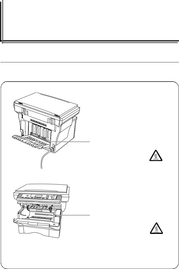
Section 1 IMPORTANT! PLEASE READ
FIRST.
 CAUTION LABELS
Caution labels have been attached to the copier at the following locations for safety purposes.
BE SUFFICIENTLY CAREFUL to avoid fire or electric shock when removing a paper jam or when replacing toner.
Label 1
High temperature inside.
Do not touch parts in this area, because there is a danger of getting burned. ……………………………………….
Label 2
High temperature inside.
Do not touch parts in this area, because there is a danger of getting burned. ……………………………………….
NOTE: DO NOT remove these labels.
1-1
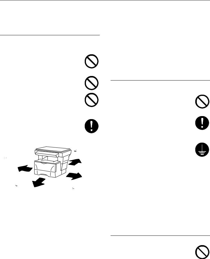
 INSTALLATION PRECAUTIONS
Environment
 CAUTION
Avoid placing the copier on or in locations which are unstable or not level. Such locations may cause the copier to fall down or fall over. This type of situation presents a danger of personal injury or damage to the
copier. …………………………………………………………………..
Avoid locations with humidity or dust and dirt. If dust or dirt become attached to the power plug, clean the plug to avoid the danger of fire or electrical shock. …………………..
Avoid locations near radiators, heaters, or other heat sources, or locations near flammable items, to avoid the danger of fire.
To keep the copier cool and facilitate changing of parts and maintenance, allow access space as shown below. Leave adequate space, especially around the vents, to allow air to be properly ventilated out of the copier.
Rear:
 11 13/16«
Left: 30 cm
 11 13/16«
30 cm
|
Front: |
Right: |
||||
|
39 |
3/8« |
||||
|
11 |
13/16« |
||||
|
100 cm |
|||||
|
30 cm |
|||||
Other precautions
Adverse environmental conditions may affect the safe operation and performance of the copier. Install in an air-conditioned room (recommended room temperature: around 68°F (20°C), humidity: around 65%) and avoid the following locations when selecting a site for the copier.
•Avoid locations near a window or with exposure to direct sunlight.
•Avoid locations with vibrations.
•Avoid locations with drastic temperature fluctuations.
•Avoid locations with direct exposure to hot or cold air.
•Avoid poorly ventilated locations.
During copying, some ozone is released, but the amount does not cause any ill effect to one’s health. If, however, the copier is used over a long period of time in a poorly ventilated room or when making an extremely large number of copies, the smell may become unpleasant. To maintain the appropriate environment for copy work, it is suggested that the room be properly ventilated.
Power supply/Grounding the copier
 WARNING
DO NOT use a power supply with a voltage other than that specified. Avoid multiple connections in the same outlet. These types of situations present a danger of fire or
electrical shock. …………………………………………………
Plug the power cord securely into the outlet. If metallic objects come in contact with the prongs on the plug, it may cause a fire or
electric shock. …………………………………………………….
Always connect the copier to an outlet with a ground connection to avoid the danger of fire or electrical shock in case of an electric short. If an earth connection is not possible, contact
your service representative. …………………………..
Other precautions
Connect the power plug to the closest outlet possible to the copier.
The power supply cord is used as the main disconnect device. Ensure that the socket/outlet is located/installed near the equipment and is easily accessible.
Handling of plastic bags
 WARNING
Keep the plastic bags that are used with the copier away from children. The plastic may cling to their nose and mouth causing
suffocation. …………………………………………………………
1-2
![]()
 PRECAUTIONS FOR USE
Cautions when using the copier
 WARNING
DO NOT place metallic objects or containers with water (flower vases, flower pots, cups, etc.) on or near the copier. This of situation presents a danger of fire or electrical shock should they fall inside. …………………………….
DO NOT remove any of the covers from the copier as there is a danger of electrical shock from high voltage parts inside the copier. ….
DO NOT damage, break or attempt to repair the power cord. DO NOT place heavy objects on the cord, pull it, bend it unnecessarily or cause any other type of damage.
These types of situations present a danger of fire or electrical shock. ……………………………..
NEVER attempt to repair or disassemble the copier or its parts as there is a danger of fire, electrical shock or damage to the laser. If the laser beam escapes, there is a danger of it causing blindness……………………………………..
If the copier becomes excessively hot, smoke appears from the copier, there is an odd smell, or any other abnormal situation occurs, there is a danger of fire or electrical shock. Turn the power switch OFF ({) immediately, BE ABSOLUTELY CERTAIN to remove the power plug from the outlet and then contact your service representative. …..
If anything harmful (paper clips, water, other fluids, etc.) falls into the copier, turn the power switch OFF ({) immediately. Next, BE ABSOLUTELY CERTAIN to remove the power plug from the outlet to avoid the danger of fire or electrical shock. Then contact your service representative. …
DO NOT remove or connect the power plug with wet hands, as there is a danger of electrical shock. ……………………………………….
ALWAYS contact your service representative for maintenance or repair of internal parts.
 CAUTION
DO NOT pull the power cord when removing it from the outlet. If the power cord is pulled, the wires may become broken and there is a danger of fire or electrical shock. (ALWAYS grasp the power plug when removing the power cord from the outlet.) …………………….
ALWAYS remove the power plug from the outlet when moving the copier. If the power cord is damaged, there is a danger of fire or electrical shock. ………………………………………
If the copier will not be used for a short period of time (overnight, etc.), turn the power switch OFF ({).
If it will not be used for an extended period of time (vacations, etc.), remove the power plug from the outlet for safety purposes during the time the copier is not in use. ………………
ALWAYS hold the designated parts only when lifting or moving the copier. …………….
For safety purposes, ALWAYS remove the power plug from the outlet when performing cleaning operations. …………………………………
If dust accumulates within the copier, there is a danger of fire or other trouble. It is therefore recommended that you consult with your service representative in regard to cleaning of internal parts. This is particularly effective if accomplished prior to seasons of high humidity. Consult with your service representative in regard to the cost of cleaning the internal parts of the copier. …..
1-3

Other precautions
DO NOT place heavy objects on the copier or cause other damage to the copier.
DO NOT open the upper front cover, turn off the power switch, or pull out the power plug during copying.
When lifting or moving the copier, contact your service representative.
Do not touch electrical parts, such as connectors or printed circuit boards. They could be damaged by static electricity.
DO NOT attempt to perform any operations not explained in this handbook.
CAUTION: Use of controls or adjustments or performance of procedures other than those specified herein may result in hazardous radiation exposure.
Do not look directly at the light from the scanning lamp as it may cause your eyes to feel tired or painful.
Cautions when handling consumables
 CAUTION
DO NOT attempt to incinerate the toner
container. Dangerous sparks may cause
burns. …………………………………………………….
Keep the toner container out of the reach of
children. …………………………………………………
If toner happens to spill from the toner
container, avoid inhalation and ingestion, as
well as contact with your eyes and skin. ……
•If you do happen to inhale toner, move to a place with fresh air and gargle thoroughly with a large amount of water. If coughing develops, contact a physician.
•If you do happen to ingest toner, rinse your mouth out with water and drink 1 or 2 cups of water to dilute the contents of your stomach. If necessary, contact a physician.
•If you do happen to get toner in your eyes, flush them thoroughly with water. If there is any remaining tenderness, contact a physician.
•If toner does happen to get on your skin, wash with soap and water.
DO NOT attempt to force open or destroy the toner container. ………………………………………
Other precautions
After use, ALWAYS dispose of the toner container in accordance with Federal, State and Local rules and regulations.
Store all consumables in a cool, dark location.
If the copier will not be used for an extended period of time, remove the paper from the drawer, return it to its original package and reseal it.
1-4
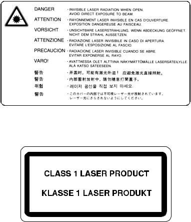
Laser Safety
Laser radiation could be hazardous to the human body. For this reason, laser radiation emitted inside this machine is hermetically sealed within the protective housing and external cover. In the normal operation of the product by user, no radiation can leak from the machine.
This machine is classified as Class 1 laser product under IEC 60825.
CAUTION
Performance of procedures other than those specified in this manual may result in hazardous radiation exposure.
This label is attached to the laser scanner unit inside the machine and is not in a user access area.
The labels shown below are attached on the rear side of the machine.
1-5
CAUTION!
The power plug is the main isolation device! Other switches on the equipment are only functional switches
and are not suitable for isolating the equipment from the power source.
VORSICHT!
Der Netzstecker ist die Hauptisoliervorrichtung! Die anderen Schalter auf dem Gerat sind nur Funktionsschalter
und konnen nicht verwendet werden, um den Stromflus im Gerat zu unterbrechen.
1-6

DECLARATION OF CONFORMITY
TO
89/336/EEC, 73/23/EEC and 93/68/EEC
We declare under our sole responsibility that the product to which this declaration relates is in conformity with the following specifications.
|
Limits and methods of measurement for immunity |
|||||
|
characteristics of information technology equipment |
EN55024 |
||||
|
Limits and methods of measurement for radio interference |
|||||
|
characteristics of information technology equipment |
EN55022 Class B |
||||
|
Limits for harmonic currents emissions |
|||||
|
for equipment input current |
16A per phase |
EN61000-3-2 |
|||
|
Limitation of voltage fluctuations and flicker in low-voltage |
|||||
|
supply systems for equipment with rated current |
16A |
EN61000-3-3 |
|||
|
Safety of information technology equipment, |
|||||
|
including electrical equipment |
EN60950 |
||||
|
Radiation Safety of laser products, equipment classification, |
|||||
|
requirements and user’s guide |
EN60825-1 |
1-7
1-8
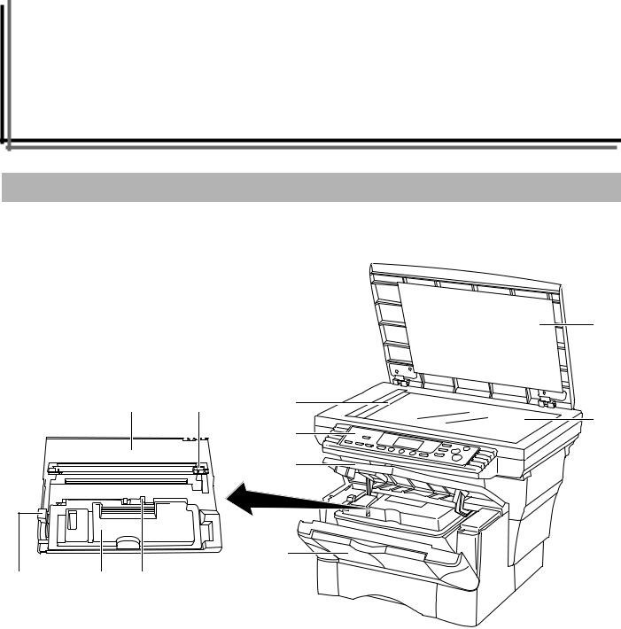
Section 2 NAMES OF PARTS
Main Body
(1)
|
(7) |
(11) |
(3) |
|
(2) |
||
|
(4) |
||
|
(5) |
(6)
(1)Original cover
(Open/close this cover when you are setting the original on the platen.)
(2)Platen
(Set originals here for copying. Be sure to lay originals face-down and align them flush up against the left rear corner of the platen.)
(3)Original size indicator plate
(Be sure to align originals flush up against this plate when setting them on the platen.)
(4)Operation panel
(Perform copy operations here.)
(5)Upper front cover
(Open this cover when you need to replace the toner container or if a paper jam occurs inside the copier.)
(6)Front cover
(Open this cover when you need to replace the toner container or if a paper jam occurs inside the copier.)
(7)Process Unit
(Open this cover when you need to replace the toner container or if a paper jam occurs inside the copier.)
(8)Toner container
(9)Lock lever
(Operate this lever when you need to replace the toner container.)
(10)Toner container release lever
(Operate this lever when you need to replace the toner container.)
(11)Charger cleaner
(Slide this knob back and forth when you need to clean the charger.)
2-1
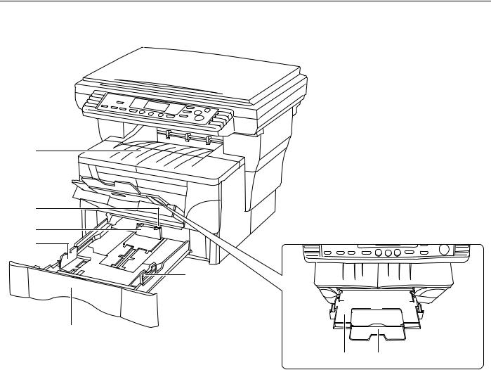
Section 2 NAMES OF PARTS
(16)
(15)
(14)
(13)
(13)
(19)
 (19)
(19)
(12)
(17) (18)
(12)Drawer
(This drawer has a storage capacity of 250 sheets of standard copy paper (80 g/m²).)
(13)Paper width guides
(Adjust these guides to fit the width of the paper that is to be loaded in the drawer.)
(14)Paper stopper
(Adjust this stopper to fit the length of the paper that is to be loaded in the drawer.)
(15)Stopper extension lock
(Use this lock when loading Folio or Oficio II size paper in the drawer.)
(16)Copy storage table
(Finished copies can be ejected and stored on this table. The copy storage table has a storage capacity of 150 sheets of standard copy paper (80 g/m²).)
(17)Multi-bypass tray
(Set paper on this tray when copying onto small-size or special paper.)
(18)Multi-bypass extension
(Pull out this extension when using the multi-bypass tray.)
(19)Insert guides
(Align these guides to fit the width of the paper that is to be set on the multi-bypass tray.)
2-2

Section 2 NAMES OF PARTS
(23)
(24)
(21)
(20)
(22)
(20)Power switch
(Turn this switch ON ( | ) before copying.)
(21)Face-up tray
(Finished copies can be ejected and stored face-up on this tray. The face-up tray should be used when copying onto thick paper and other special paper. This tray has a storage capacity of 30 sheets of standard copy paper (80 g/m²) but only 1 sheet of special paper should be stored there at one time.)
(22)Power cord
(23)Document Processor connector
(Attach the connection cable here when installing the optional Document Processor.)
(24)Right cover anchor pin
(This pin must be removed and the right cover opened in order to access the slot for installing additional memory. If you need to add additional memory, contact your service representative or an authorized service center.)
IMPORTANT!
•Be sure to hold both the front and rear sides of the copier when carrying it, as shown in the illustration.
•Be sure not to pull the drawer out when holding the front of the copier.
•Be sure that the original cover is closed whenever transporting the copier.
•DO NOT attempt to carry the copier by holding only the top portion. Doing so may result in you dropping the copier and thereby damaging the copier and/or its covers.
2-3
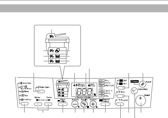
Section 2 NAMES OF PARTS
Operation panel
(24)
|
(23) |
(22) |
|||
|
(19) |
(18) |
|||
|
(21) |
(20) |
|||
|
(16) |
||||
|
(12) |
(17) |
(4) |
(13) |
(2) |
|
(6) |
(5) |
(11) |
(8) |
(9) |
(7) |
(10) |
(14) |
(1) |
|
(15) |
(3) |
(1)Start key & indicator
(Press this key when you want to start copying. Copying will begin immediately if you press this key when the indicator is lit green.)
(2)Reset/Power key
(Press this key when you want to cancel the currently entered setting(s) and return to those registered for the initial mode. Press down on this key for at least 3 seconds when you want to engage the Off mode. When you want to release the copier from the Off mode, press any one of the keys on the operation panel. See page 2-5 for details on the initial mode and
page 4-7 for details on the Off mode.)
(3)Stop/Clear key
(Press this key when you want to stop copying. Press down on this key for at least 3 seconds when you want to view the total copy count. See page 6-11.)
(4)Copy quantity/magnification display
(Displays the number of copies to be made or the currently selected magnification ratio. When the “%” symbol is lit, the displayed number is the currently selected magnification ratio.)
(5)Exposure adjustment keys
(Press the left key when you want to make the copy exposure lighter and the right key to make the exposure darker. Press down on both keys at the same time for at least 3 seconds when you want to access the default settings mode.)
(6)Image quality select key
(Press this key when you want to select the desired image quality mode. See page 4-1.)
(7)Number of Copies / Zoom(+) key
(Press this key when you want to raise the number of copies to be made, as well as to increase the currently selected copy magnification ratio. Press this key as well during default settings in order to select the desired default item or setting.)
(8)Number of Copies / Zoom(-) key
(Press this key when you want to lower the number of copies to be made, as well as to decrease the currently selected copy magnification ratio. Press this key as well during default settings in order to select the desired default item or setting.)
(9)Recall%/Enter key
(Press this key when you want copy in the Zoom mode. Press this key as well during default settings in order to select the current default item or register the currently displayed setting. See page 4-4.)
(10)Reduce/Enlarge key
(Press this key when you want to use the Preset Zoom mode. See page 4-5.)
(11)Paper Select key
(Press this key when you want to switch paper feed between the drawer(s) and the multi-bypass tray. The indicator for the currently selected source of paper feed will be lit green. Press down on this key for at least 3 seconds when you want to access the default items for paper size selection. See page 4-1.)
(12)Thick Paper key & indicator
(Press this key when you want to copy onto thick paper. Make sure that the Thick Paper indicator is lit green. See page 3-9.)
(13)2in1/4in1 key & indicator
(Press this key when you want to copy with the Layout modes. Make sure that the 2in1 or the 4in1 indicator, as appropriate, is lit green. Press down on this key for at least 3 seconds when you want to access the default items for the Layout modes. See page 5-1 for more information on the Layout modes.)
2-4
![]()
Section 2 NAMES OF PARTS
(14)Sort key & indicator
(Press this key when you want to copy with the Sort mode. Make sure that the Sort indicator is lit green. See page 5-9.)
(15)Program key & indicator
(Press this key when you want to copy with the Program function. Make sure that the Program indicator is lit green. See page 5-10.)
(16)Add Toner indicator
(This indicator lights red when the toner supply has run low. See page 9-2.)
(17)Memory Overflow indicator
(This indicator lights red if the memory becomes full during scanning of originals. See page 8-1.)
(18)Upper drawer indicator
(This indicator lights green when the upper drawer is selected as the source of paper feed and it flashes green when the drawer has run out of paper.)
(19)Upper drawer misfeed indicator
(This indicator lights red if a paper jam occurs in the upper drawer.)
(20)Paper Feeder indicator
(This indicator lights green when the optional Paper Feeder is selected as the source of paper feed and it flashes green when the drawer has run out of paper.)
(21)Paper Feeder misfeed indicator
(This indicator lights red if a paper jam occurs in the optional Paper Feeder.)
(22)Multi-bypass tray indicator
(This indicator lights green when the multi-bypass tray is selected as the source of paper feed and it flashes green when the tray has run out of paper.)
(23)Multi-bypass tray misfeed indicator
(This indicator lights red if a paper jam occurs in the multi-bypass tray.)
(24)Document Processor indicator
(This indicator will light red if an original jam occurs.)
Initial mode (the state that the copier enters at the end of warm-up or when the Reset/Power key is pressed)
The upper drawer is selected as the source for paper feed, the number of copies to be made is set to “1” and “Text & Photo” is selected as the image quality mode.
*If the optional Paper Feeder is installed on your copier, it is possible for you to change which drawer will be automatically selected in the initial mode. (See “Default Drawer” on
page 6-2.)
*It is also possible for you to change which image quality mode will be automatically selected in the initial mode. (See “Image Quality Mode” on page 6-1.)
Auto Clear function
A pre-set number of seconds (between 10 and 270) after copying stops, the Auto Clear function will automatically engage and the copier will return to the same settings as those after warm up (initial mode settings).(However, the copy exposure setting will not change.) Copies can continually be made using the same settings (copy mode and number of copies) if the next batch of copying is started before the Auto Clear function engages.
*See “Auto Clear Time” on page 6-4 for information on changing the amount of time before the Auto Clear function automatically engages, and “Auto Clear ON/OFF” on page 6-3 for information on turning the Auto Clear function ON and OFF.
Auto Drawer Switching function
If two drawers contain the same size of paper and the paper in one drawer runs out during copying, the Auto Drawer Switching function will switch paper feed from the empty drawer to the other drawer that still contains paper so that copying can continue non-stop.
*The optional Paper Feeder is required in order to use the Auto Drawer Switching function.
*It is possible for you to turn the Auto Drawer Switching function OFF. (See “Auto Drawer Switching ON/OFF” on page 6-2.)
2-5

Section 2 NAMES OF PARTS
2-6
Section 3 PREPARATIONS
Loading paper
Copy paper can either be loaded into the drawer(s) or set on the multi-bypass tray.
Note when adding paper
After taking new paper out of its packaging, be sure to fan through them a few times to separate the sheets before loading the paper into a drawer or setting it on the multi-bypass tray.
IMPORTANT!
•If you ever use paper that has already been copied onto, be sure NOT to use paper that still has staples or clips attached to it. Doing so may result in lowered copying quality or even damage to the copier.
•If you are using paper that has been folded or is curled at all, straighten it out before loading the paper into a drawer or setting it on the multi-bypass tray. Failure to do so may result in a paper jam.
Loading paper into a drawer
Standard copy paper (60 g/m² – 90 g/m²), thick paper (90 g/m² – 105 g/m²), recycled paper, or color paper can be loaded into each drawer.
Up to 250 sheets of standard copy paper (80 g/m²) can be loaded into each drawer at one time.
The sizes of paper that can be loaded into the drawers are: A4, A5R, Folio, 8 1/2» × 14″ (Legal), 8 1/2» × 11″ (Letter) and 8 1/2» × 13″ (Oficio II).
IMPORTANT!
•When loading copy paper for the first time, or when changing paper sizes, be sure to use the operation panel to register the size of paper that will be loaded in the corresponding drawer. (See page 3-4.)
•When using thick copy paper (90 g/m² – 105 g/m²), be sure to select the Thick Paper mode. (See page 3-9.)
3-1
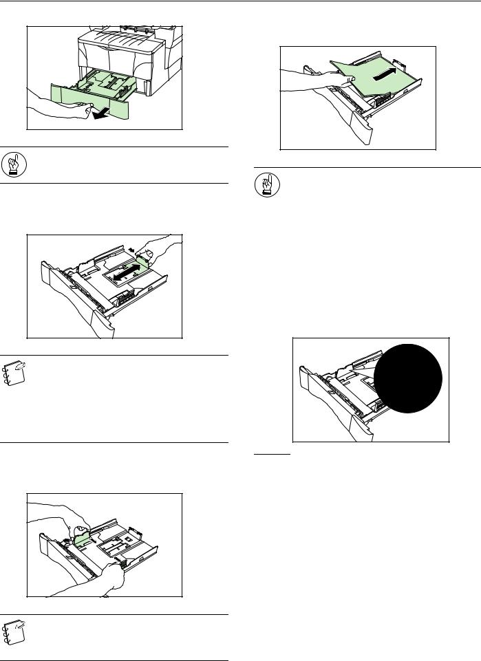
Section 3 PREPARATIONS
Pull the drawer all the way out of the copier.
4 Set the paper in the drawer so that the leading edge is aligned against the paper stopper, but making sure that none of the paper gets caught on the overhanging tabs.
When pulling the drawer out of the copier, be sure to support it so that it doesn’t fall out suddenly.
Adjust the paper stopper in the rear portion of the drawer by pressing in on the release buttons and sliding the paper stopper to the fit the size of the paper being loaded.
• The paper sizes are marked on the bottom of the drawer.
•The default factory setting is for A4/Letter size paper.
•For information on adjusting the paper stopper for Folio or Oficio II size paper, see “Adjusting the paper stopper for Folio or Oficio II size paper” on page 3-3.
Adjust the paper width guides on both sides of the drawer by pressing in on the release buttons and sliding the guides to fit the width of the paper being loaded in the drawer.
IMPORTANT!
•ALWAYS adjust the paper stopper and paper width guides BEFORE loading paper into the drawer. Failure to do so may result in skewed paper feed and/or a paper jam.
•Make sure that the paper is set securely against the paper stopper and the paper width guides. If there is any gap between the paper and the stopper or guides, readjust the paper stopper and/or the paper width guides, as appropriate.
•When you are loading paper into the drawer, make sure that the side to be copied onto is facing downward.
•Be sure to load paper so that it is not folded or curled, etc.
•DO NOT load more paper than indicated by the lines located on the width guides.
NOTES
•The paper sizes are marked on the bottom of the drawer.
•The default factory setting is for A4/Letter size paper.
3-2
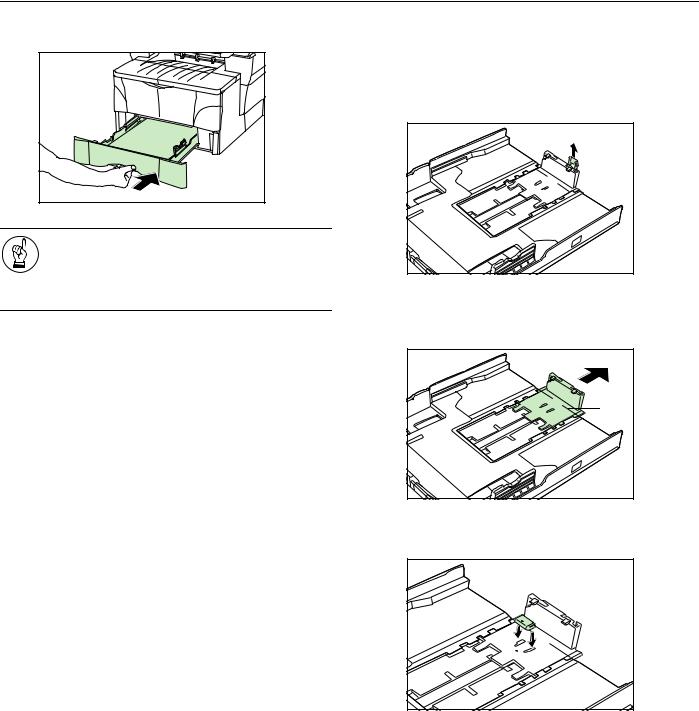
Section 3 PREPARATIONS
5 Push the drawer securely all the way back into the copier until it stops.
If you will not be using the copier for a prolonged period of time, remove all paper from the drawer(s) and seal in its original packaging in order to protect it against moisture.
Adjusting the paper stopper for Folio or Oficio II size paper
Perform the following procedure to adjust the paper stopper when you want to load Folio or Oficio II size paper into the drawer.
1 Remove the stopper extension lock from the paper stopper.
2 Slide the paper stopper towards the rear of the drawer until the grooves (1) that are cut into the paper stopper are aligned with the rear edge of the drawer.
3 Insert the stopper extension lock into the holes in the paper stopper.
3-3
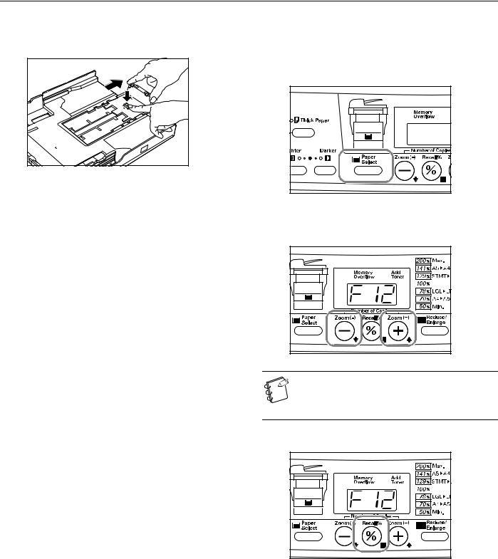
Section 3 PREPARATIONS
4 Press down on the stopper extension lock and slide the paper stopper towards the rear of the drawer to set the lock into place. The paper stopper is now in position for Folio and Oficio II size paper.
Selecting the paper size
Perform the following procedure to use the operation panel and select the size of paper that is loaded in the drawer.
1 Press down on the Paper Select key for at least 3 seconds. The first default item for paper size selection will be shown.
2 Press the Number of Copies / Zoom(+) or Number of Copies / Zoom(-) key until “F12” (Default item: Upper Drawer Paper Size) is shown.
To select the size of paper loaded into the optional Paper Feeder, make sure that “F13” (Default item: Paper Feeder Paper Size) is shown.
3 Press the Recall%/Enter key.
3-4

Section 3 PREPARATIONS
Press the Number of Copies / Zoom(+) or Number of Copies / Zoom(-) key to select the appropriate paper size. The displayed code numbers refer to the available paper sizes as explained in the following table.
|
-A4 |
A4 |
|
-A5 |
A5 |
|
-Fo |
Folio |
|
-Lg |
Legal (8 1/2» × 14″) |
|
-Lt |
Letter (8 1/2» × 11″) |
|
-o2 |
Oficio II (8 1/2» × 13″) |
Press the Recall%/Enter key.
The displayed numbers will flash and the copier will return to a copy-ready state.
Setting paper on the multi-bypass tray
Standard copy paper (60 g/m² – 90 g/m²), thick paper (90 g/m² – 163 g/m²), color paper, OHP transparencies and letterhead paper can be set on the multi-bypass tray.
ALWAYS use the multi-bypass tray when copying onto special paper.
The sizes of paper that can be set on the multi-bypass tray are as follows:
Inch Specification
8 1/2» × 14″ (Legal) – 5 1/2» × 8 1/2» (Statement)
Metric Specification
A4 – A6R, and Folio
The types of paper and the number of sheets that can be set on the multi-bypass tray at one time are as follows:
•Standard paper (80 g/m²): 50 sheets
•Thick paper (120 g/m²): 25 sheets
•Thick paper (160 g/m²): 10 sheets
•OHP transparencies: 1 sheet
IMPORTANT!
•After setting paper on the multi-bypass tray, be sure to use the operation panel to select the size of that paper. (See page 3-7.)
•If you want to copy onto non-standard size paper, be sure to use the “F15” (Non-Standard Size Paper Width) default item to register the paper size. (See page 6-3.)
•When using thick copy paper (90 g/m² – 105 g/m²), be sure to select the Thick Paper mode. (See page 3-9.)
•When using OHP transparencies, be sure to use a type of film that can withstand the heat of the fixing process. The following products are recommended: Arkwright (LTR)
3M PP2500 (A4)
3-5
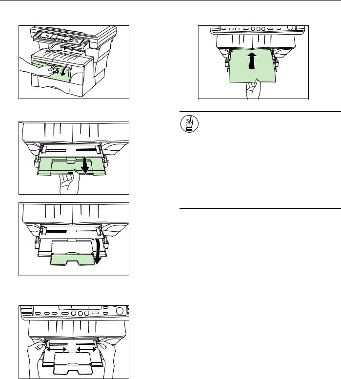
Section 3 PREPARATIONS
|
Open the multi-bypass tray towards you until you hear it |
4 |
Slide the paper all the way in, along the insert guides, as |
|
click into place. |
far as it will go. |
|
Pull out the multi-bypass extension and then flip it open. |
IMPORTANT! |
• Only set paper on the multi-bypass tray when you are planning to use that tray to feed paper. DO NOT leave paper on the multi-bypass for long periods of time.
• When you are setting paper on the multi-bypass, make sure that the side to be copied onto is facing upward.
• When using 8 1/2» × 14″ (Legal), 8 1/2» × 13″ (Oficio II) or Folio size paper, it is recommended that you load that paper into the drawer(s) and have paper fed from there. If you do need to use the multi-bypass tray and such paper does not feed smoothly, continue to support the paper by its trailing edge until all of the paper has been fed into the copier.
Adjust the insert guides to fit the width of the paper that is to be set on the multi-bypass tray.
3-6
 Loading…