-
Contents
-
Table of Contents
-
Troubleshooting
-
Bookmarks
Quick Links
Model No. PETL78132
USER’S MANUAL
Serial No.
Serial Number Decal
QUESTIONS?
As a manufacturer, we are com-
mitted to providing complete
customer satisfaction. If you
have questions, or if there are
missing or damaged parts,
please call:
08457 089 009
Or write:
ICON Health & Fitness, Ltd.
Unit 4
Revie Road Industrial Estate
Revie Road, Beeston
Leeds, LS11 8JG
UK
email: csuk@iconeurope.com
CAUTION
Read all precautions and instruc-
tions in this manual before using
Visit our website at
this equipment. Save this manual
for future reference.
www.iconeurope.com
Troubleshooting
Summary of Contents for Pro-Form 790tr Treadmill
This manual is also suitable for:
790 trPetl78132
Если у вас отсутствует техническая возможность для скачивания Руководство по эксплуатации для ProForm 790 TR (Modelnummer PETL78132)
вы можете прочесть документ прямо на нашем сайте или
Скачать ProForm 790 TR (Modelnummer PETL78132) Руководство по эксплуатации

- 1
- 2
- 3
- 4
- 5
- 6
- 7
- 8
- 9
- 10
- 11
- 12
- 13
- 14
- 15
- 16
- 17
- 18
- 19
- 20
- 21
- 22
- 23
- 24
- 25
- 26
- 27
- 28
- 29
- 30
- 31
- 32
- 33
- 34
- 35
- 36
- 37
- 38
- 39
Инструкции для прочих ProForm Домашние тренажеры
Инструкции для прочих ProForm
: Proform Proform-Petl78132-790Tr-Treadmill-Users-Manual-699088 proform-petl78132-790tr-treadmill-users-manual-699088 proform pdf
Serial Number Decal
Model No. PETL78132
Serial No.
CAUTION
Read all precautions and instruc-
tions in this manual before using
this equipment. Save this manual
for future reference.
USER’S MANUAL
QUESTIONS?
As a manufacturer, we are com-
mitted to providing complete
customer satisfaction. If you
have questions, or if there are
missing or damaged parts,
please call:
Or write:
ICON Health & Fitness, Ltd.
Unit 4
Revie Road Industrial Estate
Revie Road, Beeston
Leeds, LS11 8JG
UK
email: csuk@iconeurope.com
www.iconeurope.com
Visit our website at

TABLE OF CONTENTS
IMPORTANT PRECAUTIONS . . . . . . . . . . . . . . . . . . . . . . . . . . . . . . . . . . . . . . . . . . . . . . . . . . . . . . . . . . . . . . . .3
BEFORE YOU BEGIN . . . . . . . . . . . . . . . . . . . . . . . . . . . . . . . . . . . . . . . . . . . . . . . . . . . . . . . . . . . . . . . . . . . . . .5
ASSEMBLY . . . . . . . . . . . . . . . . . . . . . . . . . . . . . . . . . . . . . . . . . . . . . . . . . . . . . . . . . . . . . . . . . . . . . . . . . . . . . . .6
HOW TO USE THE CHEST PULSE SENSOR . . . . . . . . . . . . . . . . . . . . . . . . . . . . . . . . . . . . . . . . . . . . . . . . . . . .9
OPERATION AND ADJUSTMENT . . . . . . . . . . . . . . . . . . . . . . . . . . . . . . . . . . . . . . . . . . . . . . . . . . . . . . . . . . . .10
HOW TO FOLD AND MOVE THE TREADMILL . . . . . . . . . . . . . . . . . . . . . . . . . . . . . . . . . . . . . . . . . . . . . . . . . .27
TROUBLESHOOTING . . . . . . . . . . . . . . . . . . . . . . . . . . . . . . . . . . . . . . . . . . . . . . . . . . . . . . . . . . . . . . . . . . . . .29
CONDITIONING GUIDELINES . . . . . . . . . . . . . . . . . . . . . . . . . . . . . . . . . . . . . . . . . . . . . . . . . . . . . . . . . . . . . . .32
PART LIST . . . . . . . . . . . . . . . . . . . . . . . . . . . . . . . . . . . . . . . . . . . . . . . . . . . . . . . . . . . . . . . . . . . . . . . . . . . . . .34
ORDERING REPLACEMENT PARTS . . . . . . . . . . . . . . . . . . . . . . . . . . . . . . . . . . . . . . . . . . . . . . . . . .Back Cover
Note: An EXPLODED DRAWING is attached in the centre of this manual.
PROFORM is a registered trademark of ICON IP, Inc.
2

3
1. It is the responsibility of the owner to ensure
that all users of this treadmill are adequately
informed of all warnings and precautions.
2. Use the treadmill only as described.
3. Place the treadmill on a level surface, with at
least 2.5 m (8 ft.) of clearance behind it and
0.5 m (2 ft.) on each side. Do not place the
treadmill on any surface that blocks air open-
ings. To protect the floor or carpet from dam-
age, place a mat under the treadmill.
4. Keep the treadmill indoors, away from mois-
ture and dust. Do not put the treadmill in a
garage or covered patio, or near water.
5. Do not operate the treadmill where aerosol
products are used or where oxygen is being
administered.
6. Keep children under the age of 12 and pets
away from the treadmill at all times.
7. The treadmill should be used only by persons
weighing 125 kg (275 lbs.) or less.
8. Never allow more than one person on the
treadmill at a time.
9. Wear appropriate exercise clothes when
using the treadmill. Do not wear loose clothes
that could become caught in the treadmill.
Athletic support clothes are recommended for
both men and women. Always wear athletic
shoes. Never use the treadmill with bare feet,
wearing only stockings, or in sandals.
10. When connecting the power cord (see page
10), plug the power cord into an earthed cir-
cuit. No other appliance should be on the
same circuit. When replacing the fuse, an
ASTA approved BS1362 type should be fitted
to the fuse carrier. A 13 amp fuse should be
used.
11. If an extension cord is needed, use only a 3-
conductor, 1mm2(14-gauge) cord that is no
longer than 1.5 m (5 ft.).
12. Keep the power cord away from heated sur-
faces.
13. Never move the walking belt whilst the power
is turned off. Do not operate the treadmill if
the power cord or plug is damaged, or if the
treadmill is not working properly. (See BE-
FORE YOU BEGIN on page 5 if the treadmill is
not working properly.)
14. Never start the treadmill whilst you are stand-
ing on the walking belt. Always hold the
handrails whilst using the treadmill.
15. The treadmill is capable of high speeds.
Adjust the speed in small increments to avoid
sudden jumps in speed.
16. The pulse sensors are not medical devices.
Various factors, including the user’s move-
ment, may affect the accuracy of heart rate
readings. The pulse sensors are intended
only as exercise aids in determining heart
rate trends in general.
17. Never leave the treadmill unattended whilst it
is running. Always remove the key, unplug
the power cord and move the on/off switch to
the off position when the treadmill is not in
use. (See the drawing on page 5 for the loca-
tion of the on/off switch.)
18. Do not attempt to raise, lower, or move the
treadmill until it is properly assembled. (See
ASSEMBLY on page 6, and HOW TO FOLD
AND MOVE THE TREADMILL on page 27.)
You must be able to safely lift 20 kg (45 lbs.) to
raise, lower, or move the treadmill.
19. When folding or moving the treadmill, make
sure that the storage latch is fully closed.
20. When using iFIT.com CDs and videos, an
electronic “chirping” sound will alert you
when the speed and/or incline of the treadmill
is about to change. Always listen for the
“chirp” and be prepared for speed and/or in-
cline changes. In some instances, the speed
and/or incline may change before the per-
sonal trainer describes the change.
WARNING: To reduce the risk of burns, fire, electric shock, or injury to persons, read the
following important precautions and information before operating the treadmill.
IMPORTANT PRECAUTIONS
4
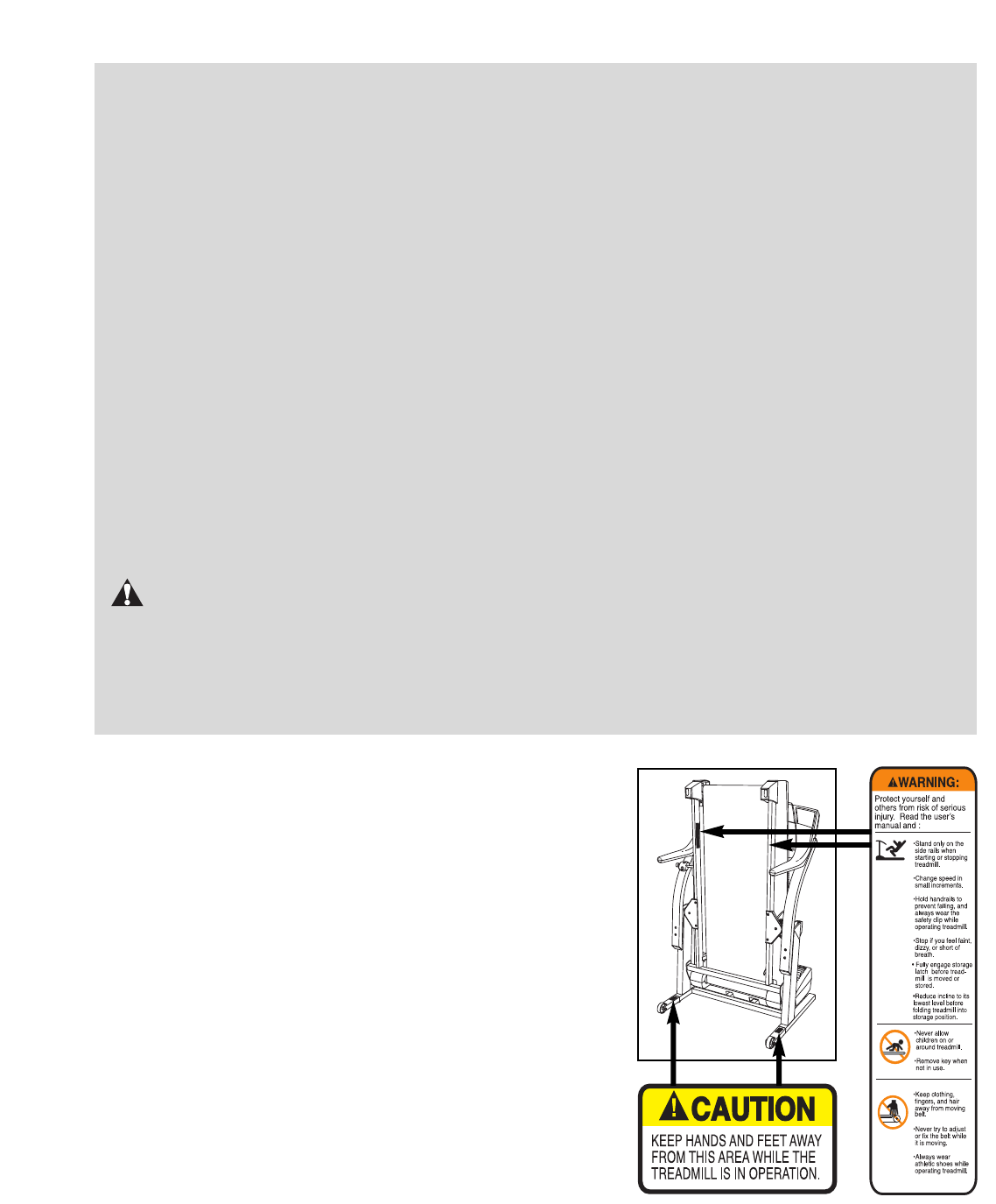
The decals shown at the right have been placed on your
treadmill. If a decal is missing or illegible, please call our
Customer Service Department to order a free replacement
decal (see ORDERING REPLACEMENT PARTS on the back
cover of this manual). Apply the decal in the location shown.
21. When using iFIT.com CDs and videos, you
can manually override the speed and incline
settings at any time by pressing the speed
and incline buttons. However, when the next
“chirp” is heard, the speed and/or incline will
change to the next settings of the CD or video
program.
22. Remove iFIT.com CDs and videos from your
CD player or VCR when you are not using
them.
23. The laser diode inside the CD player is a
Class 1M laser device. An interlock switch
prevents the CD player from being operated
whilst the cover is open. If the interlock
switch is defeated and the cover is open, do
not view the laser diode with optical magni-
fiers.
LASER RADIATION
DO NOT VIEW WITH OPTICAL MAGNIFIERS
CLASS 1M LASER PRODUCT
IEC60825-1:1993+A1+A2
788nM, 148mW
24. Inspect and properly tighten all parts of the
treadmill regularly.
25. Never insert any object into any opening.
26. DANGER:Always unplug the power
cord immediately after use, before cleaning
the treadmill, and before performing the main-
tenance and adjustment procedures de-
scribed in this manual. Never remove the
motor hood unless instructed to do so by an
authorised service representative. Servicing
other than the procedures in this manual
should be performed by an authorised service
representative only.
27. This treadmill is intended for in-home use
only. Do not use this treadmill in a commer-
cial, rental, or institutional setting.
WARNING: Before beginning this or any exercise program, consult your physician. This
is especially important for persons over the age of 35 or persons with pre-existing health problems.
Read all instructions before using. ICON assumes no responsibility for personal injury or property
damage sustained by or through the use of this product.
SAVE THESE INSTRUCTIONS
5
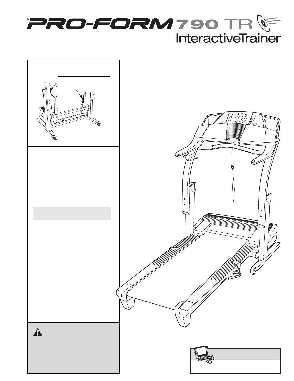
Thank you for selecting the revolutionary PROFORM®
790 TR treadmill. The 790 TR treadmill offers an im-
pressive array of features to help you achieve your fit-
ness goals in the convenience and privacy of your
home. And when you’re not exercising, the unique 790
TR treadmill can be folded up, requiring less than half
the floor space of other treadmills.
For your benefit, read this manual carefully before
using the treadmill. If you have questions after read-
ing this manual, please call our Customer Service
Department at 08457 089 009. To help us assist you,
please note the product model number and serial num-
ber before calling. The model number of the treadmill
is PETL78132. The serial number can be found on a
decal attached to the treadmill (see the front cover of
this manual for the location).
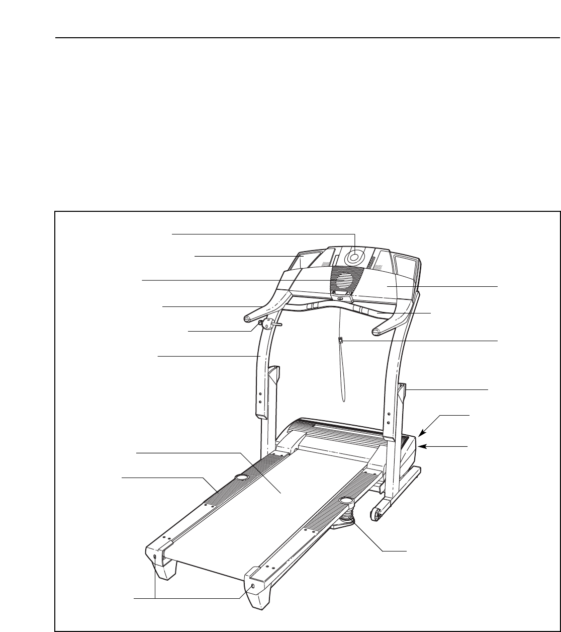
Before reading further, please review the drawing
below and familiarise yourself with the labelled parts.
BEFORE YOU BEGIN
Handrail
Upright
Storage Latch
Accessory Tray
Fan
Key/Clip
On/Off Switch
Circuit Breaker
Walking Belt
Cushioned Walking Platform
for maximum exercise comfort
Foot Rail
RIGHT SIDE
Rear Roller
Adjustment Bolts
Console
CD Player
CD Holder
Handgrip Pulse Sensor
BACK
6
ASSEMBLY
Assembly requires two persons. Set the treadmill in a cleared area and remove all packing materials. Do not
dispose of the packing materials until assembly is completed. Note: The underside of the treadmill walking belt is
coated with high-performance lubricant. During shipping, a small amount of lubricant may be transferred to the
top of the walking belt or the shipping carton. This is a normal condition and does not affect treadmill perfor-
mance. If there is lubricant on top of the walking belt, simply wipe off the lubricant with a soft cloth and a mild,
non-abrasive cleaner.
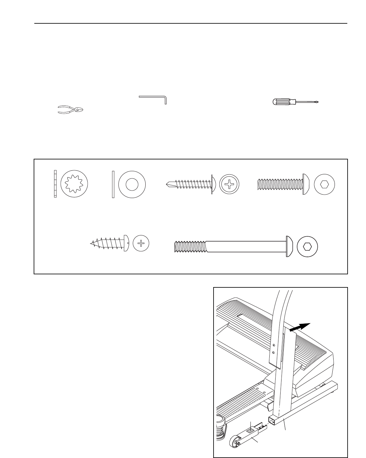
Assembly requires the included hex keys and your own phillips screwdriver and wire
cutters .
Use the drawings below to identify the assembly hardware. The number in parentheses below each drawing is
the key number of the part, from the PART LIST on pages 34 and 35. The number after the parentheses shows
the quantity needed for assembly. Note: If a part is not in the parts bag, check to see if it is preattached to
one of the parts to be assembled.
1. Make sure that the power cord is unplugged.
With the help of a second person, carefully raise the
Upright Base (97) to the position shown. Insert one of
the Extension Legs (92) into the Upright Base. (Note: It
may be helpful to tip the Upright Base forward as you in-
sert the Extension Leg.) Make sure that the Warning
Decal (91) is in the indicated location.
Insert the other Extension Leg (not shown) in the same
way.
92
97
91
1
1/4” Washer
(39)–4
Internal Star
Washer (77)–4
Console Bolt (76)–4
Latch Screw (134)–2
1” Tek Screw (135)–2 Extension Leg Bolt (96)–4
7
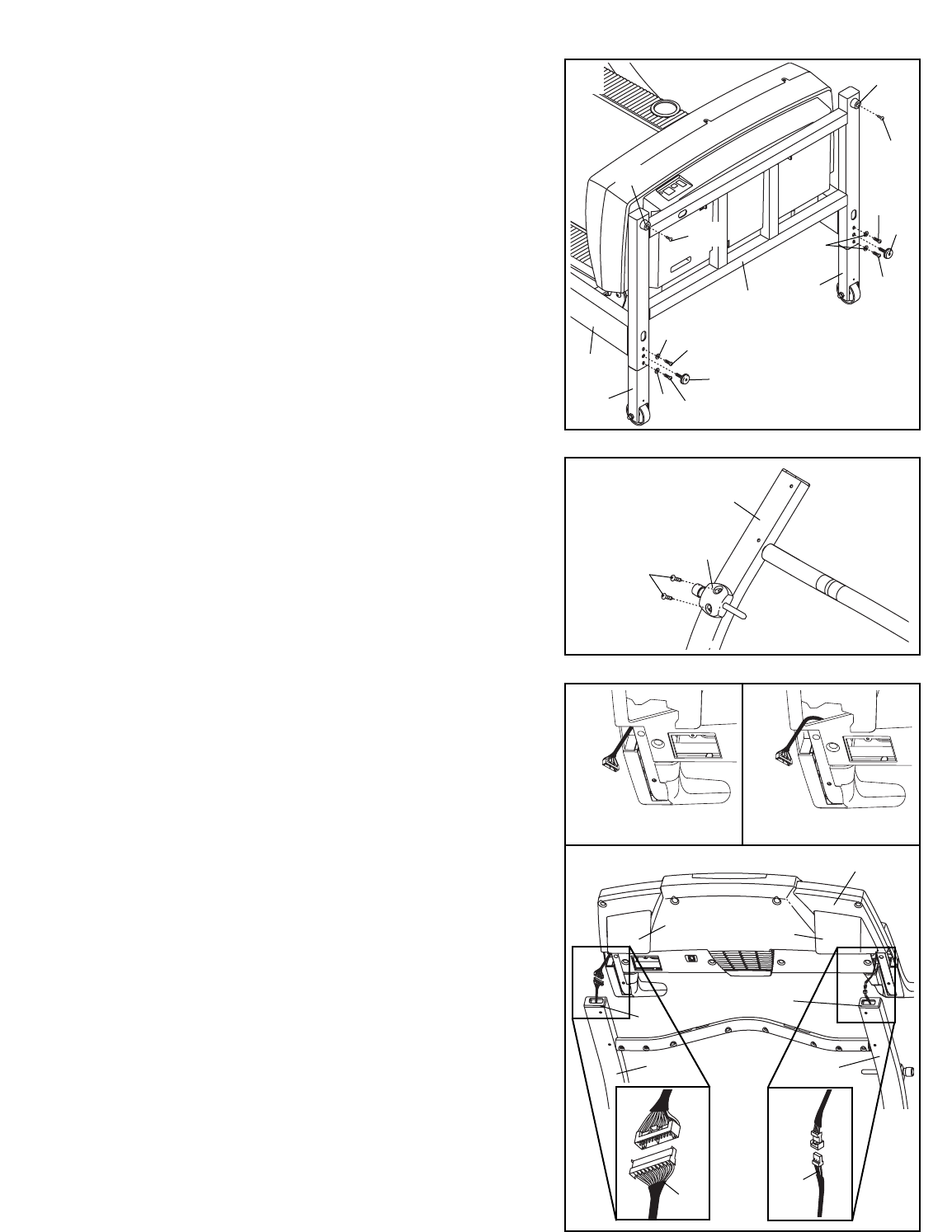
3. Attach the Latch Assembly (82) to the Left Upright (84)
with the two Latch Screws (134). Start both Latch Screws
before tightening either of them. Note: The Latch Screws
may be preattached to the Left Upright.
134
84
82
3
4. See step 6 and locate the four Upright Bolts (86). Loosen
the Upright Bolts two to three turns.
See drawing 4c. With the help of a second person, hold
the Console Base (101) near the Uprights (80, 84). Look
under the Console Base and locate the wires on the
sides of the Console Base. Make sure that the wires are
not routed through the openings for the Trays (109,
111). Drawing 4a shows the correct route for the wires.
Drawing 4b shows an incorrect route.
See drawing 4c. Cut the plastic ties holding the Wire
Harness (74) and the Pulse Wire (153) in the Uprights
(80, 84). Connect the Wire Harness and the Pulse Wire
to the wires on the sides of the Console Base (101).
Make sure to connect the connectors properly (see
the inset drawings). IF THE CONNECTORS ARE NOT
CONNECTED PROPERLY, THE CONSOLE MAY BE
DAMAGED WHEN THE POWER IS TURNED ON. The
connectors should slide together easily and snap
into place. If the connectors do not slide together easily
and snap into place, turn one connector and try again.
Insert the excess Wire Harness and Pulse Wire up into
the Console Base.
101
111 109
80
75 81
84
4a 4b
4c
Correct Incorrect
153
74
2. With the help of a second person, carefully tip the
Upright Base (97) down as shown. (Note: It may be help-
ful to place your foot on one of the Extension Legs [92]
as you tip the Upright Base.) Make sure that the
Extension Legs remain in the Upright Base.
Attach each Extension Leg (92) with two Extension Leg
Bolts (96) and two 1/4” Washers (39) as shown. Next,
thread a Levelling Foot (95) into each side of the Upright
Base (97); do not thread the Levelling Feet fully into
the Upright Base.
Attach the two Base Pads (99) to the Upright Base (97)
in the locations shown with two 1” Tek Screws (135).
With the help of a second person, raise the Upright Base
(97) to the vertical position.
96
135
135
99
99
39
96
92 95
95
96
92
96
97
39
39
97
2

8
8. Make sure that all parts are properly tightened before you use the treadmill. Note: Extra hardware may
be included. Keep the included hex keys in a secure place. The large hex key is used to adjust the walking
belt (see page 30). To protect the floor or carpet, place a mat under the treadmill. If there are thin sheets of
clear plastic on the decals, remove them.
85
80
84
85
6. Press a CD Holder (85) into each side of the Upright Base
(97).
If the Wheels (not shown) are touching the floor, or if the
treadmill rocks slightly, see HOW TO LEVEL THE
TREADMILL on page 26.
If you wish to adjust the height of the Uprights (80, 84),
go to step 7. If the Uprights are at the desired height,
tighten the four Upright Bolts (86) and go to step 8.
7. Note: The Uprights (80, 84) can be attached at three dif-
ferent heights. The Uprights are preattached in the mid-
dle position. Adjusting the Uprights requires two persons.
Whilst a second person holds the Console Base (101)
and the Uprights (80, 84), loosen the four Upright Bolts
(86). Then, remove the two Upright Bolts and Upright Star
Washers (127) from the Right Upright (80). Raise or lower
the Right Upright to the desired height, being careful not
to damage the Wire Harness (74). If the Upright Spacer
(79) falls, press it back onto the Upright Base (97).
Loosely thread the two Upright Bolts and Upright Star
Washers back into the Right Upright and the Upright Base.
Adjust the Left Upright (84) in the same way. (Note:
There is not a wire harness in the Left Upright.) Make
sure that both Uprights are at the same height. Lift
the Walking Platform (13) to make sure that it is cen-
tred between the Uprights. Retighten all four Upright
Bolts (86).
79
101
86 13
127
86
127
74
80
84
97
97
86
86
7
79
97
6
5. Set the Console Base (101) on the Uprights (80, 84).
Attach the Console Base to the each Upright with two
Console Bolts (76) and two Internal Star Washers (77).
Be careful not to pinch the Wires (not shown) in the
Uprights. Note: Start all four Console Bolts before tight-
ening any of them.
Make sure that the Left and Right Trays (109, 111) are
pressed into the Console Base (101).
76 77
101
76
77
111 109
80 84
5
77
9
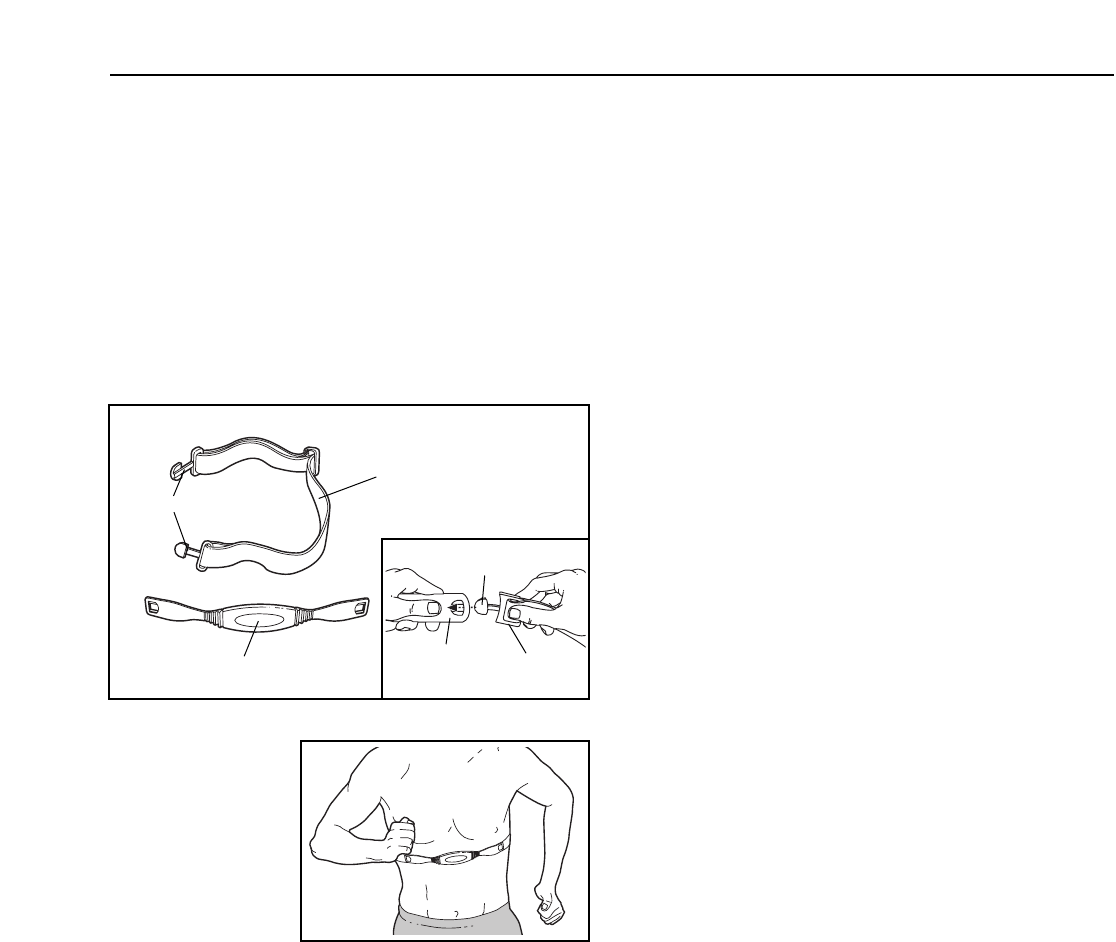
HOW TO PUT ON THE CHEST PULSE SENSOR
The chest pulse sensor consists of two components:
the chest strap and the sensor unit (see the drawing
below). Insert the tab on one end of the chest strap into
one end of the sensor unit, as shown in the inset draw-
ing. Press the end of the sensor unit under the buckle
on the chest strap. The tab should be flush with the
front of the sensor unit.
Next, wrap the
chest pulse sen-
sor around your
chest and attach
the other end of
the chest strap to
the sensor unit.
Adjust the length
of the chest strap,
if necessary. The
chest pulse sensor should be under your clothes, tight
against your skin, and as high under the pectoral mus-
cles or breasts as is comfortable. Make sure that the
logo on the sensor unit is visible and right-side-up.
Pull the sensor unit away from your body a few inches
and locate the two electrode areas on the inner side
(the electrode areas are covered by shallow ridges).
Using saline solution such as saliva or contact lens so-
lution, wet both electrode areas. Return the sensor unit
to a position against your chest.
CHEST PULSE SENSOR CARE AND MAINTENANCE
• Thoroughly dry the chest pulse sensor after each
use. The chest pulse sensor is activated when the
electrode areas are wetted and the heart rate
monitor is put on; the chest pulse sensor shuts off
when it is removed and the electrode areas are
dried. If the chest pulse sensor is not dried after
each use, it may remain activated longer than nec-
essary, draining the battery prematurely.
• Store the chest pulse sensor in a warm, dry place.
Do not store the chest pulse sensor in a plastic bag
or other container that may trap moisture.
• Do not expose the chest pulse sensor to direct
sunlight for extended periods of time; do not expose
it to temperatures above 50° C (122° F) or below
10° C (14° F).
• Do not excessively bend or stretch the sensor unit
when using or storing the chest pulse sensor.
• Clean the sensor unit using a damp cloth—never
use alcohol, abrasives, or chemicals. The chest
strap may be hand washed and air dried.
CHEST PULSE SENSOR TROUBLESHOOTING
The instructions on the following pages explain
how the chest pulse sensor is used with the con-
sole. If the chest pulse sensor does not function
properly, try the steps below.
• Make sure that you are wearing the chest pulse sen-
sor as described at the left. Note: If the chest pulse
sensor does not function when positioned as de-
scribed, move it slightly lower or higher on your chest.
• Use saline solution such as saliva or contact lens
solution to wet the two electrode areas on the
sensor unit. If heart rate readings do not appear until
you begin perspiring, rewet the electrode areas.
• As you walk or run on the treadmill, position your-
self near the centre of the walking belt. For the
console to display heart rate readings, the user
must be within arm’s length of the console.
• The chest pulse sensor is designed to work with
people who have normal heart rhythms. Heart rate
reading problems may be caused by medical
conditions such as premature ventricular contrac-
tions (pvcs), tachycardia bursts, and arrhythmia.
• The operation of the chest pulse sensor can be
affected by magnetic interference caused by high
power lines or other sources. If it is suspected that
this is a problem, try relocating the treadmill.
• The CR2032 battery may need to be replaced (see
page 31).
Chest Strap
Tabs
Sensor Unit
Tab
Sensor
Unit Buckle
HOW TO USE THE CHEST PULSE SENSOR
10
THE PERFORMANT LUBETM WALKING BELT
Your treadmill features a walking belt coated with PERFORMANT LUBETM, a high-performance lubricant. IMPOR-
TANT: Never apply silicone spray or other substances to the walking belt or the walking platform. Such
substances will deteriorate the walking belt and cause excessive wear.
HOW TO PLUG IN THE POWER CORD
This product must be earthed. If it should malfunction or break
down, earthing provides a path of least resistance for electric cur-
rent to reduce the risk of electric shock. This product is equipped
with a power cord having an equipment-earthing conductor and an
earthing plug. Important: If the power cord is damaged, it must
be replaced with a manufacturer-recommended power cord.
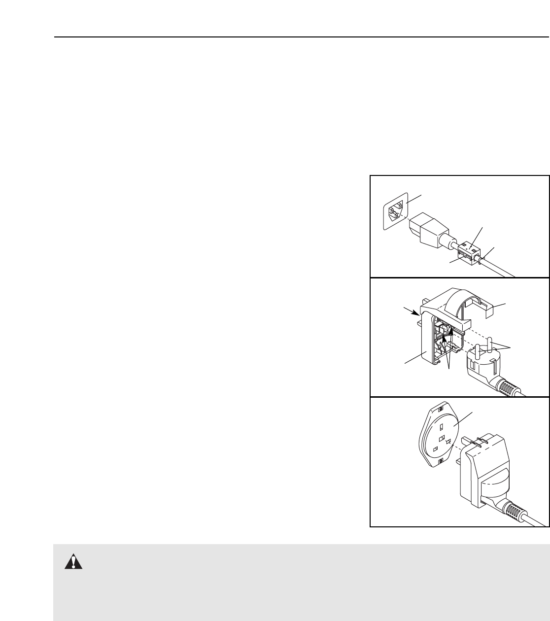
See drawing 1. Plug the indicated end of the power cord into the
socket on the treadmill. If a ferrite box is included, lift the tab on
the ferrite box and clamp the ferrite box around the power cord.
Fasten the included plastic tie just behind the ferrite box and cut off
the excess plastic tie. The plastic tie will prevent the ferrite box from
sliding along the power cord.
See drawing 2. Press the pins on the power cord into the metal clips
in the adapter as shown. Close the adapter cover over the end of the
power cord and tighten the screw in the adapter. Important: Make
sure that the adapter cover is secure and the screw has been
tightened before using the power cord.
See drawing 3. Plug the power cord into an appropriate outlet that is
properly installed and earthed in accordance with all local codes and
ordinances. Important: The treadmill is not compatible with
GFCI-equipped outlets.
Socket on Treadmill
Metal
Clips
1
2
Pins
Screw
Adapter
Outlet
3
Adapter
Cover
OPERATION AND ADJUSTMENT
DANGER: Improper connection of the equipment-earthing conductor can result in an in-
creased risk of electric shock. Check with a qualified electrician or serviceman if you are in doubt as
to whether the product is properly earthed. Do not modify the plug provided with the product—if it will
not fit the outlet, have a proper outlet installed by a qualified electrician.
Ferrite Box
Tab
Plastic Tie
11
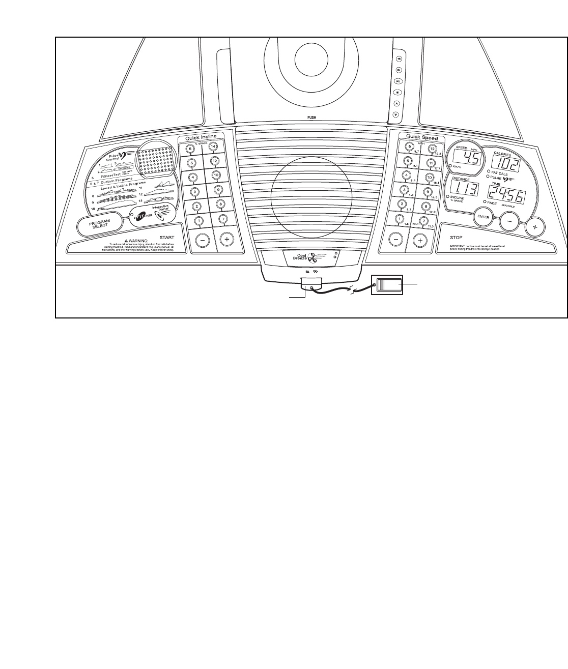
FEATURES OF THE CONSOLE
The treadmill console offers an impressive array of
features that help you get the most from your workouts.
When the manual mode of the console is selected, the
speed and incline of the treadmill can be changed with
the touch of a button. As you exercise, the console will
display instant exercise feedback. You can even mea-
sure your heart rate using the handgrip pulse sensor or
the chest pulse sensor.
The console also offers six preset programs. Each pro-
gram automatically controls the speed and incline of the
treadmill as it guides you through an effective workout.
Four pulse programs are also offered. Each program
adjusts the speed and incline of the treadmill to keep
your heart rate near a target heart rate whilst you exer-
cise. In addition, a fitness test program measures your
VO2 max level. You can even create custom programs
and save them in memory for future workouts.
The console also features iFIT.com interactive technol-
ogy. Having iFIT.com technology is like having a per-
sonal trainer in your home. Using the built-in CD player,
you can play iFIT.com CD programs that automatically
control the speed and incline of the treadmill as a per-
sonal trainer guides you through every step of your
workout. High-energy music provides added motivation.
To purchase iFIT.com CDs, visit our Web site at
www.iFIT.com.
Using the included audio cable, you can also connect
the treadmill to your VCR and TV and play iFIT.com
video programs. Video programs offer the same bene-
fits as iFIT.com CD programs, and allow you to enjoy
breathtaking scenery whilst you exercise. To purchase
iFIT.com videocassettes, visit our Web site at
www.iFIT.com.
You can also connect the treadmill to your home com-
puter and access programs directly from our Web site.
Visit www.iFIT.com for more information.
To use the manual mode of the console, follow the
steps beginning on page 12. To use a preset program,
see page 14. To use a pulse program, see page 16.
To use the fitness test program, see page 18. To cre-
ate and use a custom program, see pages 19 and
20. To use an iFIT.com CD program, see page 21. To
play your own music CD, see page 22. To use an
iFIT.com video program, see page 24. To use an
iFIT.com program directly from our Web site, see
page 25.
Note: If there are thin sheets of clear
plastic on the console, remove them.
Clip
Key
12
HOW TO TURN ON THE POWER
Plug in the power cord (see page 10).
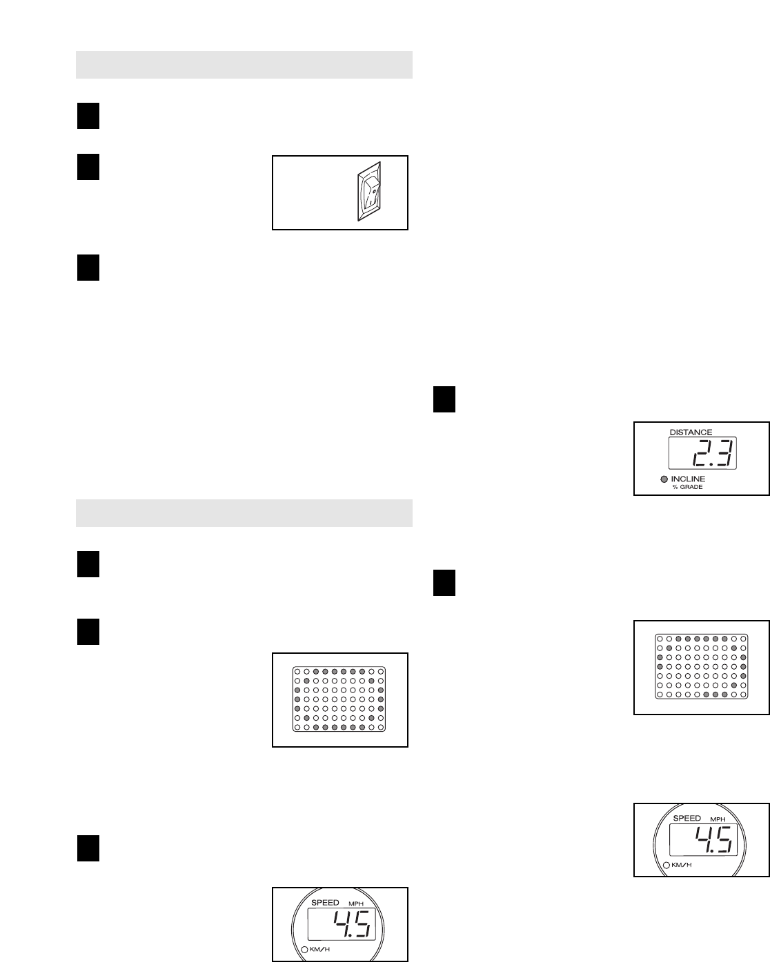
Locate the on/off switch
on the treadmill near
the power cord. Move
the on/off switch to the
on position.
Stand on the foot rails of the treadmill. Find the clip
attached to the key (see the drawing on page 11)
and slide the clip onto the waistband of your
clothes. Next, route the cord attached to the clip
under the handgrip pulse sensor, and insert the
key into the console. After a moment, the displays
and various indicators will light. Test the clip by
carefully taking a few steps backward until the
key is pulled from the console. If the key is not
pulled from the console, adjust the position of
the clip.
HOW TO USE THE MANUAL MODE
Insert the key fully into the console.
See HOW TO TURN ON THE POWER above.
Select the manual mode.
When the key is in-
serted, the manual
mode will be selected.
If you have selected a
program, select the
manual mode by press-
ing the Program Select
button repeatedly until a track appears in the ma-
trix. Make sure that the indicator on the iFIT.com
button is not lit.
Press the Start button or the Speed + button to
start the walking belt.
A moment after the but-
ton is pressed, the
walking belt will begin to
move at 1 mph. Hold
the handrails and begin
walking. As you exercise, change the speed of the
walking belt as desired by pressing the Speed +
and – buttons. Each time a button is pressed, the
speed setting will change by 0.1 mph; if a button
is held down, the speed setting will change in in-
crements of 0.5 mph. To change the speed setting
quickly, press the Quick Speed buttons. Note: The
console can display speed and distance in ei-
ther miles or kilometres. For simplicity, all in-
structions in this section refer to miles.
To stop the walking belt, press the Stop button.
The Time/Pace display will begin to flash. To
restart the walking belt, press the Start button or
the Speed + button.
Note: The first time the treadmill is used, observe
the alignment of the walking belt, and align the
walking belt if necessary (see page 30).
Change the incline of the treadmill as desired.
To change the incline of
the treadmill, press the
Incline + and – buttons.
Each time a button is
pressed, the incline will
change by 0.5%. To
change the incline setting quickly, press the Quick
Incline buttons.
Follow your progress with the matrix and the
displays.
The matrix—When the
manual mode or the
iFIT.com mode is se-
lected, the matrix will
display a 1/4-mile track.
As you exercise, the in-
dicators around the track
will light in succession until the entire track is lit.
The track will then darken and the indicators will
again begin to light in succession.
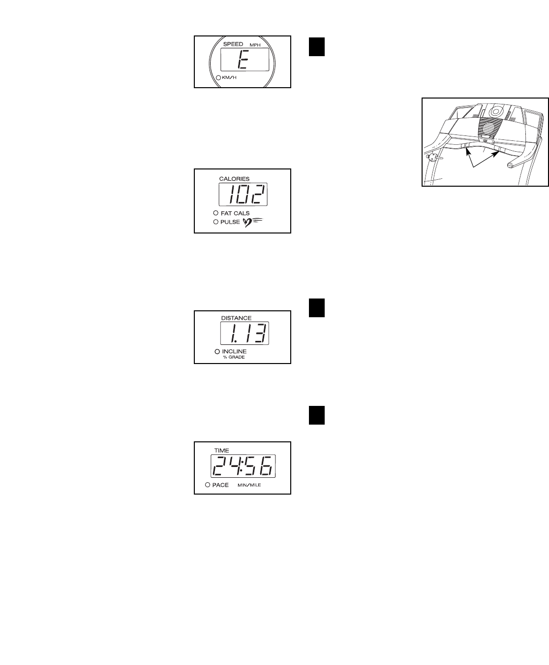
Speed display—This
display shows the speed
of the walking belt. Note:
When the KM/H indica-
tor is lit, the console will
display speed and dis-
tance in kilometres; when the KM/H indicator is
not lit, the console will display speed and distance
in miles.
5
4
3
2
1
3
2
1
On
Position
13
To change the unit of
measurement, first hold
down the Stop button
whilst inserting the key
into the console. An “E”
for English miles or an
“M” for metric kilometres will appear in the Speed
display. Press the Speed + button to change the
unit of measurement. When the desired unit of
measurement is selected, remove the key.
Calories/Pulse
display—This display
shows the approximate
numbers of calories and
fat calories you have
burned (see FAT BURN-
ING on page 32). The
display will change from one number to the other
every few seconds. The display will also show
your heart rate when you use the handgrip pulse
sensor or the chest pulse sensor.
Distance/Incline dis-
play—This display
shows the distance that
you have walked or run
and the incline level of
the treadmill. The display
will change from one number to the other every
few seconds. Note: Each time the incline changes,
the display will show the incline setting for several
seconds.
Time/Pace display—
When the manual mode
or the iFIT.com mode is
selected, this display will
show the elapsed time
and your current pace
(pace is measured in minutes per mile). The dis-
play will change from one number to the other
every few seconds. When a program is selected
(except for pulse program 4), the display will show
the time remaining in the program rather than the
elapsed time.
To reset the displays, press the Stop button, re-
move the key, and then reinsert the key.
Measure your heart rate if desired.
You can measure your heart rate using either the
chest pulse sensor or the handgrip pulse sensor.
To use the hand-
grip pulse sen-
sor, first make
sure that your
hands are clean.
Next, stand on
the foot rails
and hold the
handgrip pulse
sensor, with your palms on the metal contacts.
Avoid moving your hands. When your pulse is
detected, two dashes (– –) will appear in the
Calories/Pulse display, and then your heart rate
will be shown. For the most accurate heart rate
reading, continue to hold the contacts for
about 15 seconds.
Turn on the fan if desired.
To turn on the fan, press the button below the fan.
To turn on the fan at high speed, press the button
a second time. To turn off the fan, press the but-
ton a third time. Note: A few minutes after the
walking belt is stopped, the fan will automatically
turn off.
When you are finished exercising, remove the
key from the console.
Step onto the foot rails, press the Stop button, and
adjust the incline of the treadmill to the lowest
setting. The incline must be at the lowest setting
when the treadmill is folded to the storage posi-
tion or the treadmill will be damaged. Next, re-
move the key from the console and put it in a se-
cure place. Note: If the displays and various indi-
cators on the console remain lit after the key is
removed, the console is in the “demo” mode.
See page 26 and turn off the demo mode.
When you are finished using the treadmill, move
the on/off switch near the power cord to the off
position and unplug the power cord.
8
7
6
Contacts
14
HOW TO USE PRESET PROGRAMS
Insert the key fully into the console.
See HOW TO TURN ON THE POWER on page
12.
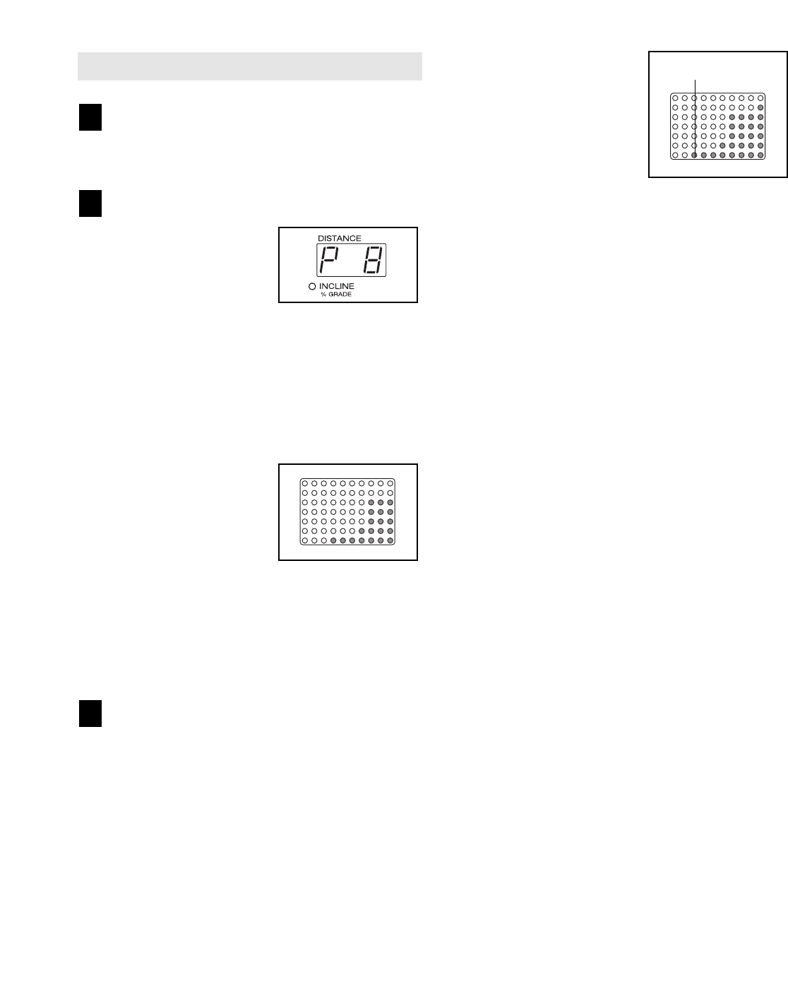
Select one of the preset programs.
When the key is in-
serted, the manual mode
will be selected. To se-
lect a preset program,
press the Program
Select button repeatedly
until a “P 8,” “P 9,” “P 10,” “P 11,” “P 12,” or “P 13”
appears in the Distance/Incline display.
When a preset program is selected, the Speed
display will flash the maximum speed setting of
the program for a few seconds. The Time/Pace
display will show how long the program will last.
The matrix will show
the first seven speed
settings of the program.
Note: The diagrams
numbered 8 through 13
on the left side of the
console show how the
speed and incline will change during the preset
programs. For example, diagram number 12
shows that during preset program 12, the speed
will gradually increase during the first half of the
program and then gradually decrease during the
last half; the incline will remain constant.
Press the Start button or the Speed + button to
start the program.
A moment after the button is pressed, the tread-
mill will automatically adjust to the first speed and
incline settings of the program. Hold the handrails
and begin walking.
Each program is divided into several time seg-
ments of different lengths. One speed setting and
one incline setting are programmed for each seg-
ment. Note: The same speed setting and/or in-
cline setting may be programmed for two or more
consecutive segments.
The speed setting for the
first segment is shown in
the flashing Current
Segment column of the
matrix. (The incline set-
tings are not shown in
the matrix.) The speed
settings for the next
seven segments are
shown in the seven columns to the right.
When only three seconds remain in the first seg-
ment of the program, both the Current Segment
column and the column to the right will flash and a
series of tones will sound. If the speed and/or in-
cline of the treadmill is about to change, the Speed
display and/or the Distance/Incline display will
flash to alert you. When the first segment ends, all
speed settings will move one column to the left.
The speed setting for the second segment will then
be shown in the flashing Current Segment column
and the treadmill will automatically adjust to the
speed and incline settings for the second segment.
Note: If all of the indicators in the Current Segment
column are lit after the speed settings have moved
to the left, the speed settings may move downward
so that only the highest indicators appear in the
matrix. If some of the indicators in the Current
Segment column are not lit when the speed set-
tings move to the left again, the speed settings will
move back up.
The program will continue in this way until the
speed setting for the last segment is shown in the
Current Segment column of the matrix and the
last segment ends. The walking belt will then slow
to a stop.
If the speed or incline setting is too high or too low
at any time during the program, you can manually
override the setting by pressing the Speed or
Incline buttons. Every few times a Speed button is
pressed, an additional indicator will light or darken
in the Current Segment column. (If any of the
columns to the right of the Current Segment col-
umn have the same number of lit indicators as the
Current Segment column, an additional indicator
may light or darken in those columns as well.)
Note: When the next segment of the program
begins, the treadmill will automatically adjust
to the speed and incline settings for the next
segment.
3
2
1
Current Segment

15
To stop the program at any time, press the Stop
button. The Time/Pace display will begin to flash.
To restart the program, press the Start button or
the Speed + button. The walking belt will begin to
move at 1 mph. When the next segment of the pro-
gram begins, the treadmill will automatically adjust
to the speed and incline settings for the next seg-
ment.
Follow your progress with the displays.
See step 5 on page 12.
Measure your heart rate if desired.
See step 6 on page 13.
Turn on the fan if desired.
See step 7 on page 13.
When you are finished exercising, remove the
key from the console.
When the program has ended, make sure that
the incline of the treadmill is at the lowest set-
ting. Next, remove the key from the console and
put it in a secure place. Note: If the displays and
various indicators on the console remain lit
after the key is removed, the console is in the
“demo” mode. See page 26 and turn off the
demo mode.
When you are finished using the treadmill, move
the on/off switch near the power cord to the off
position and unplug the power cord.
7
6
5
4
HOW TO USE PULSE PROGRAMS
Put on the chest pulse sensor.
You must wear the chest pulse sensor to use a
pulse program. See the instructions on page 9.
Insert the key fully into the console.
See HOW TO TURN ON THE POWER on
page 12.
Select a pulse program.
When the key is in-
serted, the manual
mode will be selected.
To select a pulse pro-
gram, press the
Program Select button
repeatedly until a “P 1,” “P 2,” “P 3,” or “P 4” ap-
pears in the Distance/Incline display.
The diagrams numbered 1 through 4 on the left
side of the console show how the target heart rate
will change during the programs. During pulse
program 1, your heart rate will reach approxi-
mately 85% of your estimated maximum heart
rate; during pulse programs 2 and 3, your heart
rate will reach approximately 80% of your esti-
mated maximum heart rate; during pulse program
4, your heart rate will remain near a level that you
select.
Note: Your estimated maximum heart rate is de-
termined by subtracting your age from 220. For
example, if you are 30 years old, your estimated
maximum heart rate is 190 beats per minute
(220 – 30 = 190).
During pulse programs,
the matrix will show a
moving graphic that rep-
resents your heart rate.
Each time a heartbeat is
detected, an additional
peak will appear.
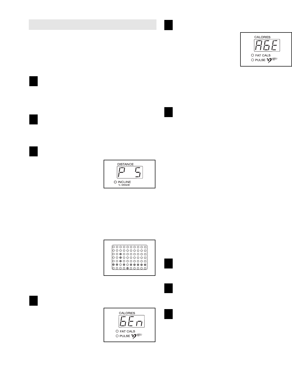
Enter your age.
When a pulse program
is selected, the word
“AGE” and the current
age setting will flash in
the Calories/Pulse dis-
play. If you have already
entered your age, simply
press the Enter button. If you have not entered
your age, press the + and – buttons beside the
Enter button to enter your age. Then, press the
Enter button.
Enter a target heart rate.
If pulse program 1, 2, or 3 is selected, go to
step 6. If pulse program 4 is selected, follow
the instructions below.
After you have entered
your age, the letters
“PLS” and the target
heart rate setting for the
program will flash in the
Calories/Pulse display. If
desired, press the + and
– buttons beside the Enter button to adjust the tar-
get heart rate setting. When the desired setting is
shown, press the Enter button.
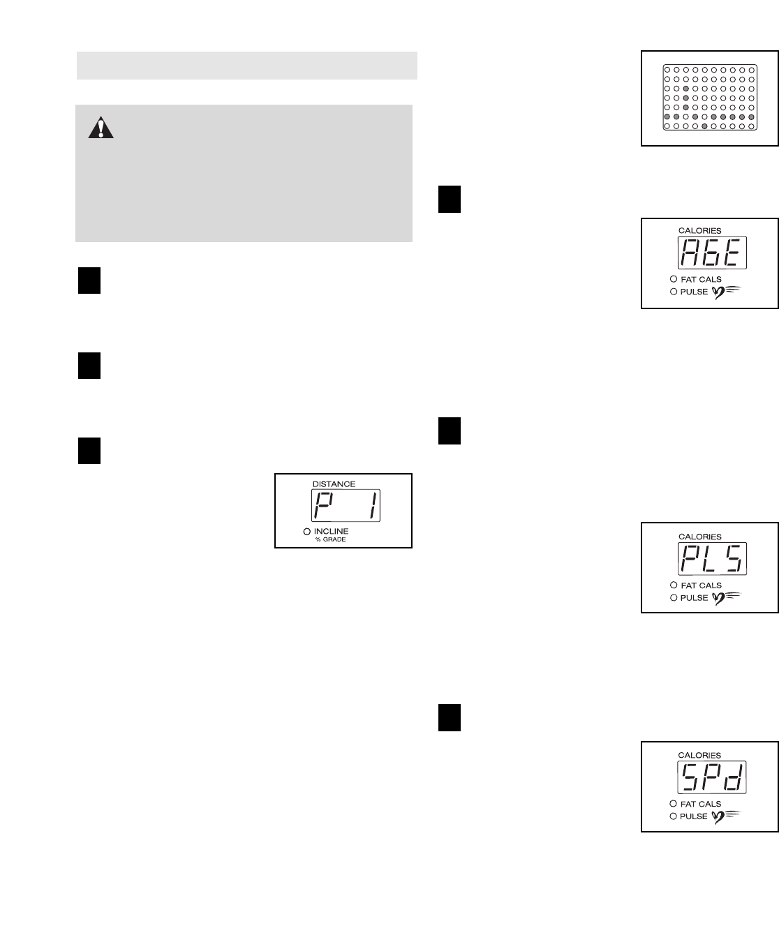
Enter a maximum speed.
Next, the letters “SPd”
and the maximum speed
setting of the program
will flash in the Calories/
Pulse display. If desired,
press the + and – but-
tons beside the Enter
button to adjust the maximum speed setting.
When the desired setting is shown, press the
Enter button.
6
5
4
3
2
1
16
CAUTION:If you have heart prob-
lems, or if you are over 60 years of age and
have been inactive, do not use the pulse pro-
grams. If you are taking medication regularly,
consult your physician to find whether the
medication will affect your exercise heart rate.

17
Press the Start button or the Speed + button to
start the program.
A moment after the button is pressed, the tread-
mill will automatically adjust to the first speed and
incline settings of the program. Hold the handrails
and begin walking.
Each pulse program is divided into several time
segments of different lengths. One target heart rate
is programmed for each segment. Note: If pulse
program 4 is selected, the same target heart rate
is programmed for all segments.
During each segment, the console will regularly
compare your heart rate to the current target heart
rate. If your heart rate is too far below or above
the target heart rate, the speed of the treadmill will
automatically increase or decrease to bring your
heart rate closer to the target heart rate. If the
speed reaches the maximum speed setting of the
program (see step 6 on page 16) and your heart
rate is still too far below the current target heart
rate, the incline of the treadmill will also increase
to bring your heart rate closer to the target heart
rate.
During the last three seconds of each segment, a
series of tones will sound and the Speed display
and the Distance/Incline display will flash.
The program will continue until the last segment
ends. The walking belt will then slow to a stop.
If the speed or incline setting is too high or too low
at any time during the program, you can adjust the
setting with the Speed or Incline buttons. However,
each time the console compares your heart rate to
the current target heart rate, the speed and/or in-
cline of the treadmill may automatically change to
bring your heart rate closer to the target heart rate.
If your pulse is not detected during the program,
the letters “PLS” will flash in the Calories/Pulse
display and the speed and incline of the treadmill
may automatically decrease until your pulse is de-
tected. If this occurs, see CHEST PULSE SEN-
SOR TROUBLESHOOTING on page 9.
To stop the program at any time, press the Stop
button. Pulse programs cannot be stopped tem-
porarily and then restarted. To use a pulse pro—
gram again, reselect the program and start it at
the beginning.
Follow your progress with the displays.
See step 5 on page 12.
Turn on the fan if desired.
See step 7 on page 13.
When you are finished exercising, remove the
key from the console.
See step 7 on page 15.
9
8
7
10
HOW TO USE THE FITNESS TEST PROGRAM
The fitness test program measures your VO2 max
level. For the best results, the program should be used
at a time when your energy level is high; the program
should not be used if you have already exercised dur-
ing the day. Follow the steps below to use the program.
Put on the chest pulse sensor.
You must wear the chest pulse sensor to use
the fitness test program. See the instructions on
page 9.
Insert the key fully into the console.
See HOW TO TURN ON THE POWER on page
12.
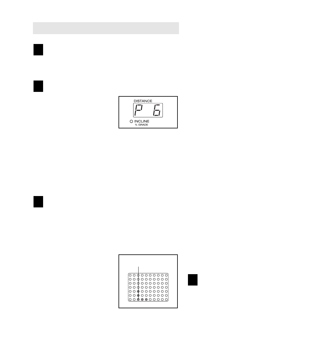
Select the fitness test program.
When the key is inserted,
the manual mode will be
selected. To select the
fitness test program,
press the Program
Select button repeatedly
until a “P 5” appears in the Distance/Incline dis-
play.
When the fitness test program is selected, the
Time/Pace display will show that the program is 9
minutes long.
During the fitness test
program, the matrix will
show a moving graphic
that represents your
heart rate. Each time a
heartbeat is detected,
an additional peak will
appear.
Enter your gender.
When the fitness test
program is selected, the
letters “GEn” (gender)
and an “m” (male) or an
“F” (female) will flash in
the Calories/Pulse dis-
play. Press the + and –
buttons beside the Enter button to select a gen-
der, and then press the Enter button.
Enter your age.
After you have entered
your gender, the word
“AGE” and the current
age setting will flash in
the Calories/Pulse dis-
play. If you have already
entered your age, simply
press the Enter button. If you have not entered
your age, press the + and – buttons beside the
Enter button to enter your age. Then, press the
Enter button.
Press the Start button or the Speed + button to
start the program.
A moment after the button is pressed, the tread-
mill will automatically adjust to the first speed and
incline settings of the program. Hold the handrails
and begin walking.
During the fitness test program, the console will
automatically control the speed and incline of the
treadmill. When the program is completed, the
walking belt will slow to a stop and your VO2 max
level will appear in the Time/Pace display.
Note: If your heart rate exceeds 70% of your esti-
mated maximum heart rate during the first part of
the program, if your heart rate exceeds 85% of
your estimated maximum heart rate for more than
a few seconds at any time during the program, or
if your pulse is not detected for several seconds
during the program (the letters “PLS” will flash in
the Calorie/Pulse display), the fitness test will stop
and a zero (0) will appear in the Time/Pace display.
Follow your progress with the main display.
See step 5 on page 12.
Turn on the fan if desired.
See step 7 on page 13.
When you are finished exercising, remove the
key from the console.
See step 7 on page 15.
9
8
7
6
5
4
3
2
1
18
19
HOW TO CREATE CUSTOM PROGRAMS
Insert the key fully into the console.
See HOW TO TURN ON THE POWER on page
12.
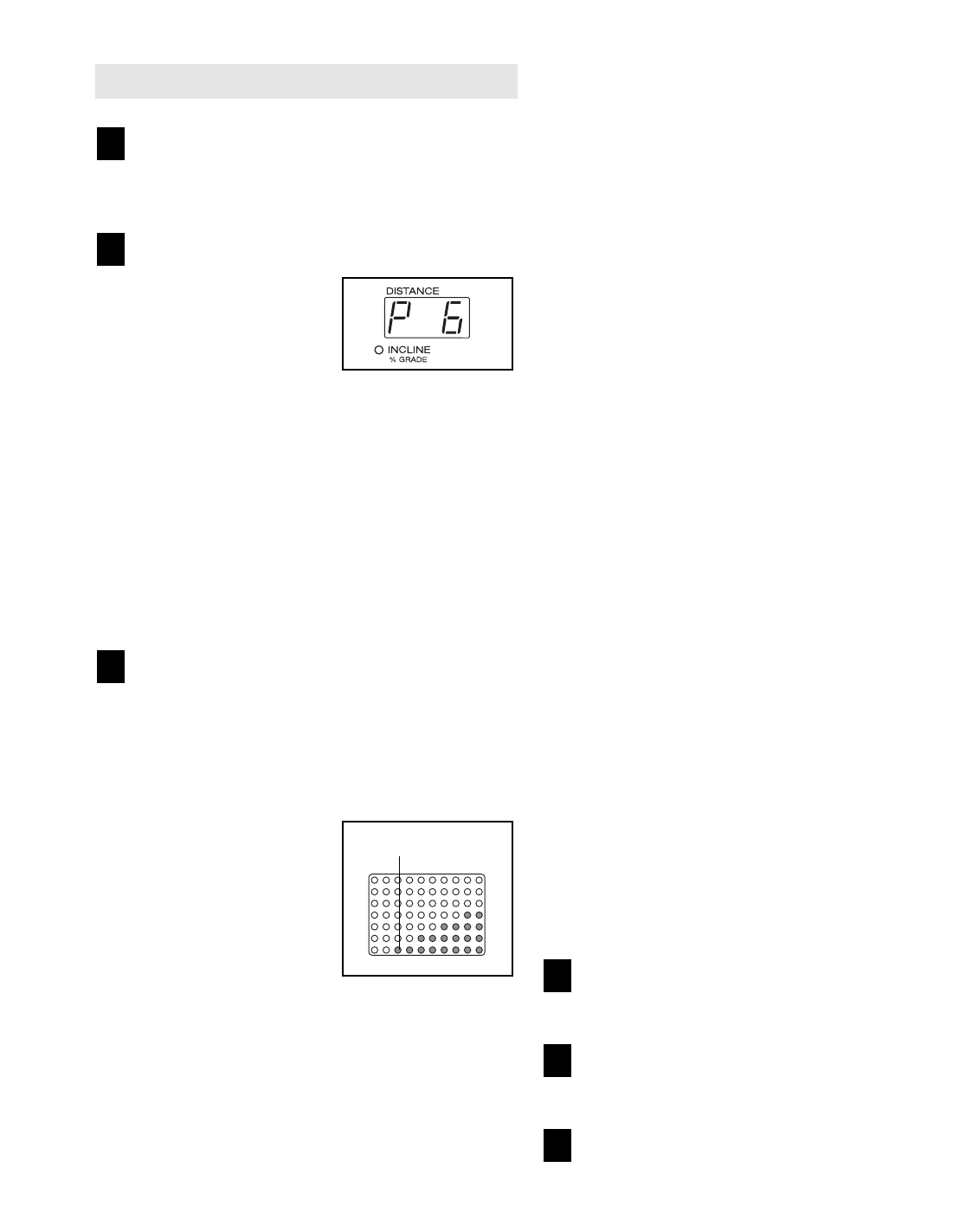
Select one of the custom programs.
When the key is inserted,
the manual mode will be
selected. To select a
custom program, press
the Program Select but-
ton repeatedly until a “P
6” or “P 7” appears in the Distance/Incline display.
Note: If the custom program has not yet been
defined, three columns of indicators will be lit
in the matrix. If more than three columns of in-
dicators are lit, see HOW TO USE CUSTOM
PROGRAMS on page 20.
Press the Start button or the Speed + button
and program the desired speed and incline
settings.
A moment after the button is pressed, the walking
belt will begin to move. Hold the handrails and
begin walking.
See the matrix. Each
custom program is di-
vided into one-minute
segments. One speed
setting and one incline
setting can be pro-
grammed for each seg-
ment. The speed setting
for the first segment will
be shown in the flashing Current Segment column
of the matrix. (The incline settings are not shown
in the matrix.) To program a speed setting and an
incline setting for the first segment, simply adjust
the speed and incline of the treadmill as desired
by pressing the Speed and Incline buttons. Every
few times one of the Speed buttons is pressed, an
additional indicator will light or darken in the
Current Segment column.
When the first segment of the program is com-
pleted, the current speed setting and the current
incline setting will be saved in memory. The three
columns of indicators will then move one column
to the left, and the speed setting for the second
segment will be shown in the flashing Current
Segment column. Program a speed setting and an
incline setting for the second segment as de-
scribed above. Note: After the third segment is
completed, the columns of indicators in the matrix
will no longer move to the left. Instead, each time
a segment is completed, the flashing Current
Segment column will move one column to the
right. If the Current Segment column reaches the
right side of the matrix, when the current segment
is completed all columns of indicators in the matrix
will move three columns to the left.
Continue programming speed and incline settings
for as many segments as desired; custom pro-
grams can have up to forty segments. When you
are finished with your workout, press the Stop but-
ton twice. The speed and incline settings that you
have programmed and the number of segments
that you have programmed will then be saved in
memory.
When the program is finished, remove the key.
See step 7 on page 15.
4
3
2
1
Current Segment
20
HOW TO USE CUSTOM PROGRAMS
Insert the key fully into the console.
See HOW TO TURN ON THE POWER on
page 12.
Select one of the custom programs.
When the key is in-
serted, the manual mode
will be selected. To se-
lect a custom program,
press the Program
Select button repeatedly
until a “P 6” or “P 7” appears in the
Distance/Incline display.
When a custom program is selected, the Speed
display will flash the maximum speed setting of
the program for a few seconds. The Time/Pace
display will show how long the program will last.
Note: If only three columns of indicators are lit
in the matrix, see HOW TO CREATE A CUS-
TOM PROGRAM on page 19.
Press the Start button or the Speed + button to
start the program.
A moment after the button is pressed, the tread-
mill will automatically adjust to the first speed and
incline settings that you programmed previously.
Hold the handrails and begin walking.
Each custom program is
divided into several
one-minute segments.
One speed setting and
one incline setting are
programmed for each
segment. The speed
setting for the first seg-
ment will be shown in
the flashing Current Segment column of the ma-
trix. (The incline settings are not shown in the ma-
trix.) The speed settings for the next seven seg-
ments will be shown in the columns to the right.
When only three seconds remain in the first seg-
ment of the program, both the Current Segment
column and the column to the right will flash, a se-
ries of tones will sound, the Speed display and the
Distance/Incline display will flash, and all speed
settings will move one column to the left. The
speed setting for the second segment will then be
shown in the flashing Current Segment column
and the treadmill will automatically adjust to the
second speed and incline settings that you pro-
grammed previously.
The program will continue until the speed setting
for the last segment is shown in the Current
Segment column and the last segment ends. The
walking belt will then slow to a stop.
If desired, you can redefine to the program whilst
using it. To change the speed or incline setting
during the current segment, simply press the
Speed or Incline buttons. When the current segment
is completed, the new setting will be saved in mem-
ory. To increase the length of the program, first
wait until the program is completed. Then, press the
Start button and program speed and incline settings
for as many additional segments as desired. (Note:
Whilst you are adding segments to the program,
the speed settings in the matrix will not move to
the left. Instead, each time a segment is com-
pleted, the flashing Current Segment column will
move one column to the right. If the Current
Segment column reaches the right side of the ma-
trix, when the current segment is completed all
columns of indicators in the matrix will move three
columns to the left.) When you have added as
many segments as desired, press the Stop button
twice. To decrease the length of the program,
press the Stop button twice at any time before the
program is completed.
To stop the program at any time, press the Stop
button. The Time/Pace display will begin to flash.
To restart the program, press the Start button or
the Speed + button. The walking belt will begin to
move at 1 mph. When the next segment of the pro-
gram begins, the treadmill will automatically adjust
to the speed and incline settings for the next seg-
ment.
Follow your progress with the displays.
See step 5 on page 12.
Measure your heart rate if desired.
See step 6 on page 13.
When you are finished exercising, remove the
key from the console.
See step 7 on page 15.
6
5
4
3
2
1
Current Segment
HOW TO USE IFIT.COM CD PROGRAMS
When you use an iFIT.com CD program, a certified
personal trainer will guide you through your workout as
the program interactively controls the speed and in-
cline of the treadmill. Note: To purchase iFIT.com
CDs, visit our Web site at www.iFIT.com.
Follow the steps below to use an iFIT.com CD program.
Insert the key into the console.
See HOW TO TURN ON THE POWER on page 12.
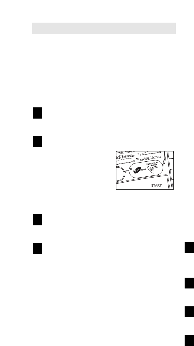
Select the iFIT.com mode.
When the key is in-
serted, the manual
mode will be selected.
To use iFIT.com CDs,
press the iFIT.com but-
ton. The indicator on
the button will light.
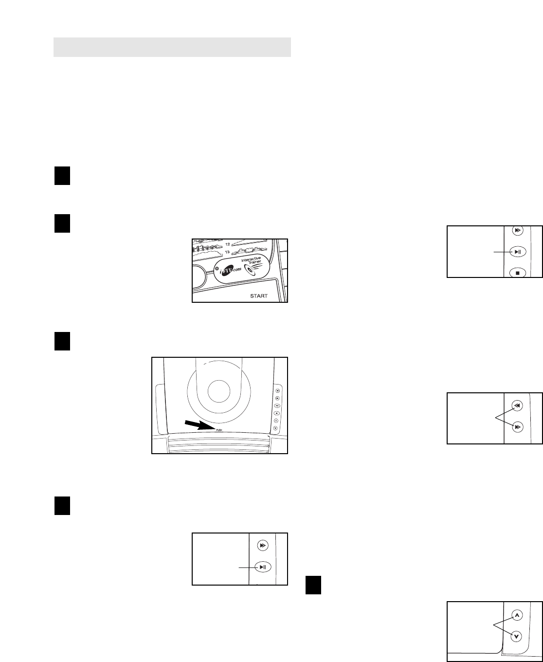
Insert an iFIT.com CD into the CD player.
To open the
CD player,
press the lid of
the CD player
in the indi-
cated location.
Carefully in-
sert an
iFIT.com CD
into the CD
player and close the lid.
Press the Play/Pause button to start the
program.
To start the CD pro-
gram, press the Play/
Pause button beside
the CD player. A mo-
ment after the button is
pressed, your personal
trainer will begin guiding you through your workout.
Simply follow your personal trainer’s instructions.
Note: If the Time/Pace display is flashing, press
the Start button or the Speed + button on the con-
sole. The treadmill will not respond to a CD pro-
gram whilst the Time/Pace display is flashing.
During the CD program, an electronic “chirping”
sound will alert you when the speed and/or incline
of the treadmill is about to change. CAUTION:
Always listen for the “chirp” and be prepared
for speed and/or incline changes. In some in-
stances, the speed and/or incline may change
before the personal trainer describes the
change.
If the speed or incline settings are too high or too
low, you can manually override the settings at any
time by pressing the Speed or Incline buttons on
the console. However, when the next “chirp” is
heard, the speed and/or incline will change to
the next settings of the CD program.
To stop the program at
any time, press the Stop
button on the console
and then press the
Play/Pause button be-
side the CD player. The
Time/Pace display will begin to flash. To restart
the program, press the Play/Pause button and
then press the Start button or the Speed + button
on the console. After a moment, the walking belt
will begin to move at 1 mph. When the next
“chirp” is heard, the speed and incline will
change to the next settings of the CD program.
When the CD program is
completed, the walking
belt will slow to a stop
and the Time/Pace dis-
play will begin to flash.
Note: To select a differ-
ent program on the CD, press the Skip/Search
buttons beside the CD player.
Note: If the speed or incline of the treadmill
does not change when a “chirp” is heard, make
sure that the iFIT.com indicator is lit and that
the Time/Pace display is not flashing. If the
Time/Pace display is flashing, press the Start
button or the Speed + button on the console.
Adjust the volume if desired.
To adjust the volume,
press the Volume but-
tons beside the CD
player.
5
4
3
2
1
Play/
Pause
Play/
Pause
Volume
21
Skip/
Search

22
Follow your progress with the matrix and the
displays.
See step 5 on page 12.
Measure your heart rate if desired.
See step 6 on page 13.
Turn on the fan if desired.
See step 7 on page 13.
When you are finished exercising, remove the
key from the console.
See step 7 on page 15.
CAUTION: Always remove iFIT.com CDs from
the CD player when you are finished using
them.
HOW TO PLAY MUSIC CDS
If desired, you can play your own music CDs in the CD
player. Before playing music CDs, select the manual
mode of the console (see HOW TO USE THE MAN-
UAL MODE on page 12). Note: Due to the nature of
CD players, the ability of the player to read a CD-
RW disk whilst a user is running vigorously on the
treadmill may be affected by factors such as the
condition of the CD-RW and the quality of the
burner used to create the CD-RW.
You can also use your own headphones with the CD
player. Headphones with foam ear cushions are rec-
ommended to minimise the chances of static electricity
shock. Plug your headphones into the jack below the
fan. Secure the headphone wire to your clothing to
keep the wire out of your way.
9
8
7
6
WARNING:The laser diode inside
the CD player is a Class 1M laser device. An in-
terlock switch prevents the CD player from
being operated whilst the cover is open. If the
interlock switch is defeated and the cover is
open, do not view the laser diode with optical
magnifiers.
LASER RADIATION
DO NOT VIEW WITH OPTICAL MAGNIFIERS
CLASS 1M LASER PRODUCT
IEC60825-1:1993+A1+A2
788nM, 148mW
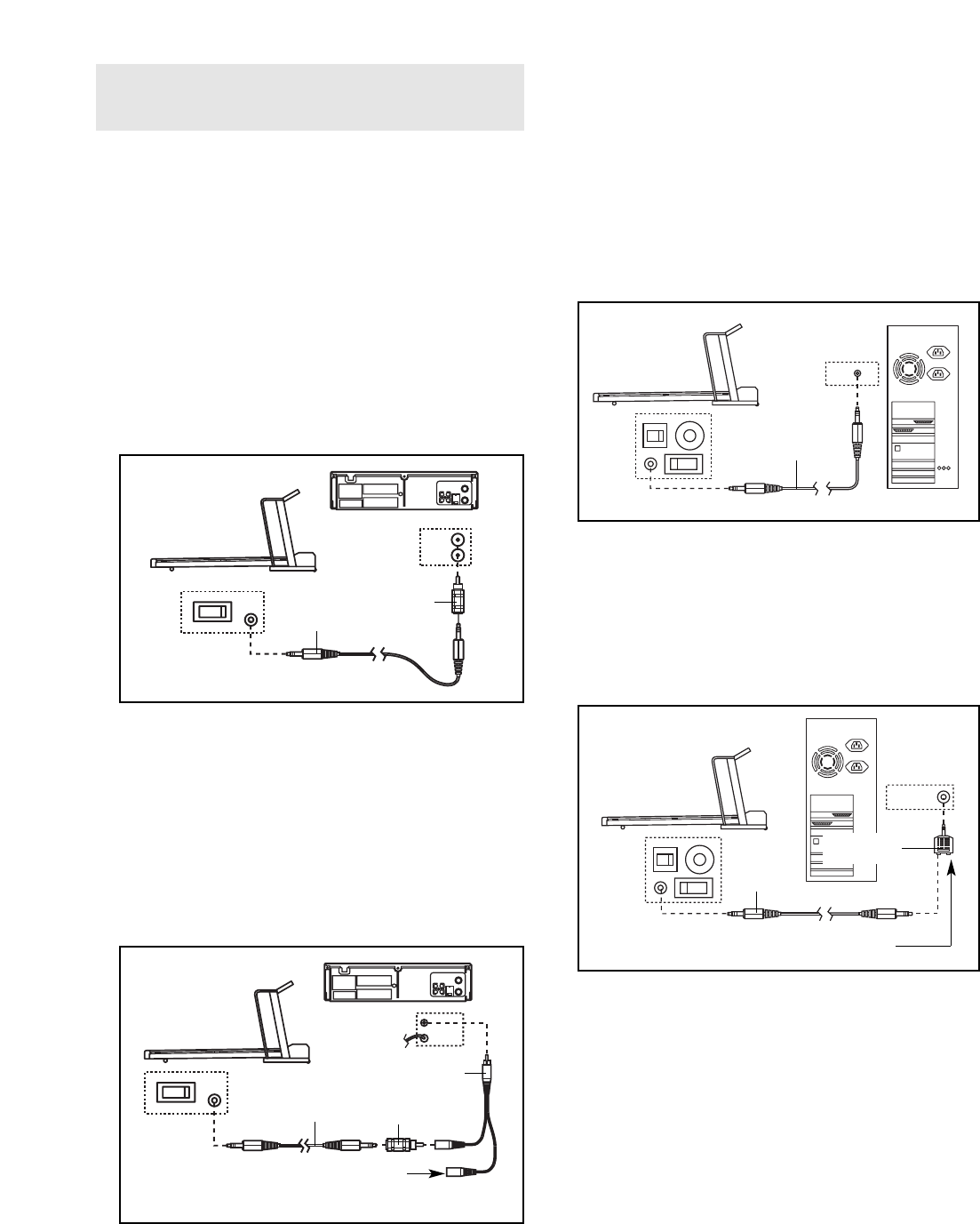
HOW TO CONNECT THE TREADMILL TO YOUR
VCR
Note: If your VCR has an unused AUDIO OUT jack,
see instruction A below. If the AUDIO OUT jack is
being used, see instruction B. If you have a TV
with a built-in VCR, see instruction B.
A. Plug one end of the audio cable into the jack on the
front of the treadmill near the power cord. Plug the
other end of the cable into the included adaptor.
Plug the adaptor into the AUDIO OUT jack on your
VCR.
B. Plug one end of the audio cable into the jack on the
front of the treadmill near the power cord. Plug the
other end of the cable into the included adaptor.
Plug the adaptor into an RCA Y-adaptor (available
at electronics stores). Next, remove the wire that is
currently plugged into the AUDIO OUT jack on your
VCR and plug the wire into the unused side of the
Y-adaptor. Plug the Y-adaptor into the AUDIO OUT
jack on your VCR.
HOW TO CONNECT YOUR COMPUTER
Note: If your computer has a 3.5 mm LINE OUT jack,
see instruction A. If your computer has only a
PHONES jack, see instruction B.
A. Plug one end of the audio cable into the jack on the
front of the treadmill near the power cord. Plug the
other end of the cable into the LINE OUT jack on
your computer.
B. Plug one end of the audio cable into the jack on the
front of the treadmill near the power cord. Plug the
other end of the cable into the splitter. Plug the split-
ter into the PHONES jack on your computer. Plug
your headphones or speakers into the other side of
the splitter.
23
AUDIO OUT
RIGHT
LEFT
VIDEO AUDIO
ANT. IN
RF OUT
IN
OUT
CH
34
VIDEO AUDIO
ANT. IN
RF OUT
IN
OUT
CH
34
Audio
Cable adaptor
B
Wire removed from
AUDIO OUT jack
RCA Y-adaptor
LINE OUT
Audio
Cable
A
HOW TO CONNECT THE TREADMILL TO YOUR
VCR OR COMPUTER
PHONES
Audio
Cable
B
Splitter
Headphones/Speakers
24
HOW TO USE IFIT.COM VIDEO PROGRAMS
To use iFIT.com videocassettes, the treadmill must be
connected to your VCR. See HOW TO CONNECT
THE TREADMILL TO YOUR VCR on page 23. Note:
To purchase iFIT.com videocassettes, visit our
Web site at www.iFIT.com.
Follow the steps below to use an iFIT.com video pro-
gram.
Insert the key into the console.
See HOW TO TURN ON THE POWER on page 12.
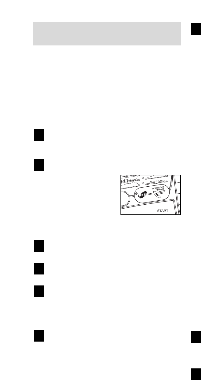
Select the iFIT.com mode.
When the key is in-
serted, the manual
mode will be selected.
To use an iFIT.com
video program, press
the iFIT.com button.
The indicator on the
button will light.
Insert the iFIT.com videocassette.
Insert the videocassette into your VCR.
Press the PLAY button on your VCR.
A moment after the button is pressed, your per-
sonal trainer will begin guiding you through your
workout. Simply follow your personal trainer’s
instructions. Note: If the Time/Pace display is
flashing, press the Start button or the Speed +
button on the console. The treadmill will not re-
spond to a video program whilst the Time/Pace
display is flashing.
During the video program, an electronic “chirping”
sound will alert you when the speed and/or incline
of the treadmill is about to change. CAUTION:
Always listen for the “chirp” and be prepared
for speed and/or incline changes. In some in-
stances, the speed and/or incline may change
before the personal trainer describes the
change.
If the speed or incline settings are too high or too
low, you can manually override the settings at any
time by pressing the Speed or Incline buttons on
the console. However, when the next “chirp” is
heard, the speed and/or incline will change to
the next settings of the video program.
To stop the walking belt at any time, press the
Stop button on the console. The Time/Pace dis-
play will begin to flash. To restart the program,
press the Start button or the Speed + button. After
a moment, the walking belt will begin to move at 1
mph. When the next “chirp” is heard, the
speed and incline will change to the next set-
tings of the video program.
When the video program is completed, the walking
belt will stop and the Time/Pace display will begin
to flash. Note: To use another video program,
press the Stop button or remove the key and go to
step 1 on this page.
Note: If the speed or incline of the treadmill
does not change when a “chirp” is heard:
• Make sure that the iFIT.com indicator is lit and
that the Time/Pace display is not flashing. If
the Time/Pace display is flashing, press the
Start button or the Speed + button on the
console.
• Adjust the volume of your VCR. If the volume
is too high or too low, the console may not
detect the program signals.
• Make sure that the audio cable is properly
connected, that it is fully plugged in, and that
it is not wrapped around a power cord.
Follow your progress with the matrix and the
displays.
See step 5 on page 12.
Measure your heart rate if desired.
See step 6 on page 13.
Turn on the fan if desired.
See step 7 on page 13.
When you are finished exercising, remove the
key from the console.
See step 7 on page 15.
CAUTION: Always remove iFIT.com videocas-
settes from your VCR when you are finished
using them.
8
7
6
5
4
3
2
1
25
HOW TO USE PROGRAMS DIRECTLY FROM
OUR WEB SITE
To use programs from our Web site, the treadmill must
be connected to your home computer. See HOW TO
CONNECT THE TREADMILL TO YOUR COMPUTER
on page 23. In addition, you must have an internet
connection and an internet service provider. A list of
specific system requirements is found on our Web site.
Follow the steps below to use a program from our
Web site.
Insert the key into the console.
See HOW TO TURN ON THE POWER on page 12.
Select the iFIT.com mode.
When the key is in-
serted, the manual
mode will be selected.
To use a program from
our Web site, press the
iFIT.com button. The in-
dicator on the button
will light.
Go to your computer and start an internet
connection.
Start your web browser, if necessary, and go to
our Web site at www.iFIT.com.
Follow the desired links on our Web site to se-
lect a program.
Read and follow the on-line instructions for using a
program.
Follow the on-line instructions to start the
program.
When you start the program, an on-screen count-
down will begin.
Return to the treadmill and stand on the foot
pads. Find the clip attached to the key and slide
the clip onto the waistband of your clothes.
When the on-screen countdown ends, the program
will begin and the walking belt will begin to move.
Hold the handrails, step onto the walking belt, and
begin walking. During the program, an electronic
“chirping” sound will alert you when the speed
and/or incline of the treadmill is about to change.
CAUTION: Always listen for the “chirp” and be
prepared for speed and/or incline changes.
If the speed or incline settings are too high or too
low, you can manually override the settings at any
time by pressing the Speed or Incline buttons on
the console. However, when the next “chirp” is
heard, the speed and/or incline will change to
the next settings of the program.
To stop the walking belt at any time, press the
Stop button on the console. The Time/Pace dis-
play will begin to flash. To restart the program,
press the Start button or the Speed + button. After
a moment, the walking belt will begin to move at 1
mph. When the next “chirp” is heard, the speed
and incline will change to the next settings of
the program.
When the program is completed, the walking belt
will stop and the Time/Pace display will begin to
flash. Note: To use another program, press the
Stop button and go to step 5.
Note: If the speed or incline of the treadmill
does not change when a “chirp” is heard, make
sure that the iFIT.com indicator is lit and that
the Time/Pace display is not flashing. In addi-
tion, make sure that the audio cable is properly
connected, that it is fully plugged in, and that it
is not wrapped around a power cord.
Follow your progress with the matrix and the
displays.
See step 5 on page 12.
When you are finished exercising, remove the
key from the console.
See step 7 on page 15.
9
8
7
6
5
4
3
2
1
THE INFORMATION MODE/DEMO MODE
The console features an information mode that keeps
track of the total number of hours that the treadmill has
been operated and the total number of miles that the
walking belt has moved. The information mode also al-
lows you to switch the console from miles per hour to
kilometres per hour. In addition, the information mode
allows you to turn on and turn off the demo mode.
To select the information mode, hold down the Stop
button whilst inserting the key into the console. When
the information mode is selected, the following informa-
tion will be shown:
The Distance/Incline display
will show the total number of
miles (or kilometres) that the
walking belt has moved.
The Time/Pace display will
show the total number of
hours the treadmill has been
used.
An “E” for English miles or
an “M” for metric kilometres
will appear in the Speed dis-
play. Press the Speed + but-
ton to change the unit of
measurement.
IMPORTANT: The Calories/Pulse display should be
blank. If a “d” appears in the display, the console is in
the “demo” mode. This mode is intended to be used
only when a treadmill is displayed in a store. When the
console is in the demo mode, the power cord can be
plugged in, the key can be removed from the console,
and the displays and indicators on the console will au-
tomatically light in a preset sequence, although the
buttons on the console will not operate. If a “d” appears
in the Calories/Pulse display when the information
mode is selected, press the Speed – button so the
display is blank.
To exit the information mode, remove the key.
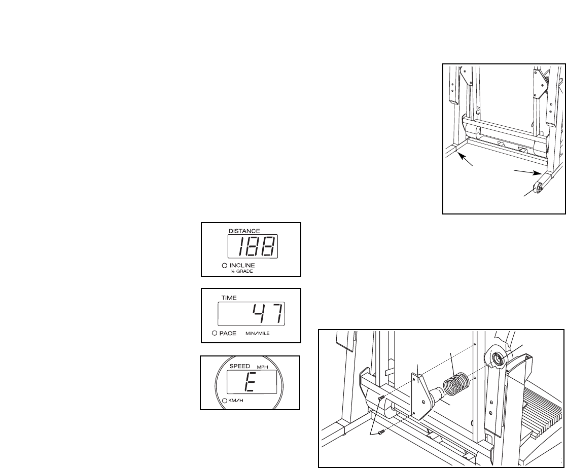
HOW TO LEVEL THE TREADMILL
If the treadmill wheels
are touching the floor or
if the treadmill rocks
slightly, turn one or both
of the levelling feet
under the upright base
until the wheels are off
the floor and the rocking
motion is eliminated.
Note: If necessary, tip
the treadmill and use a
phillips screwdriver to
turn the levelling feet.
CHANGING THE ISOLATOR SPRINGS
The treadmill features Isolator Springs (6) that cushion
the walking platform. A pair of Gray Isolator Springs is
preinstalled on the treadmill. For a firmer walking plat-
form, the Gray Isolator Springs can be removed and
the included Blue Isolator Springs can be installed.
Fold the treadmill to the storage position (see page
21). Using a hex key, remove the two Isolator Bracket
Bolts (12) from one of the Isolator Brackets (10).
Remove the Gray Isolator Spring (6) from the Isolator
(7) and slide a Blue Isolator Spring onto the Isolator.
Insert the Isolator back into the circular channel in the
Isolator Top Cap (5), and reattach the Isolator Bracket
with the Isolator Bracket Bolts; start both Isolator
Bracket Bolts before tightening either of them.
Replace the other Gray Isolator Spring (6) in the same
way.
Levelling
Feet
Wheel
12
10 65
7
26
HOW TO FOLD AND MOVE THE TREADMILL
HOW TO FOLD THE TREADMILL FOR STORAGE
Before folding the treadmill, adjust the incline to the
lowest position. If this is not done, the treadmill may be per-
manently damaged. Next, unplug the power cord. CAUTION:
You must be able to safely lift 20 kg (45 lbs.) to raise, lower,
or move the treadmill.
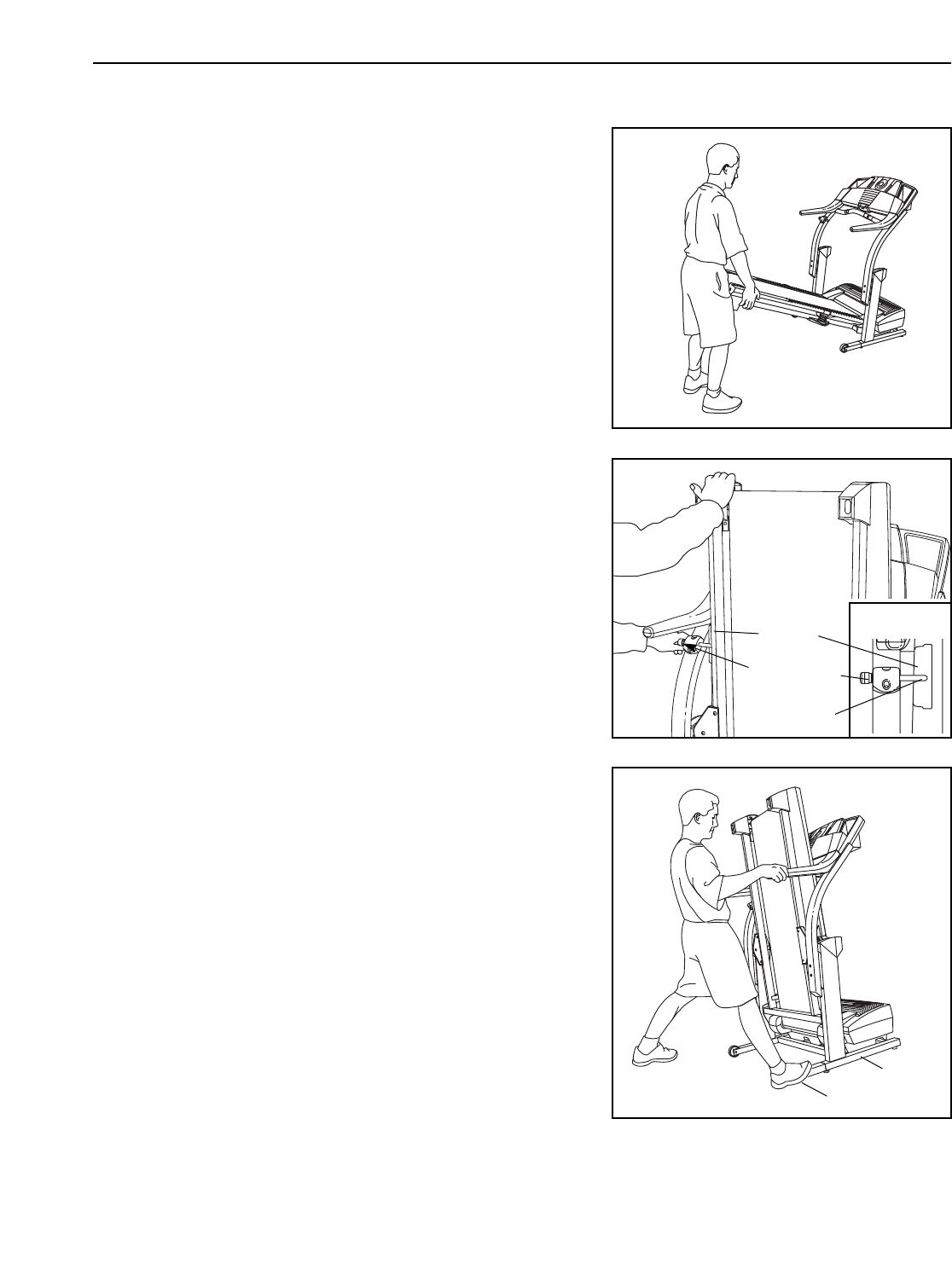
1. Hold the treadmill with your hands in the locations shown at the
right. To decrease the possibility of injury, bend your legs
and keep your back straight. As you raise the treadmill,
make sure to lift with your legs rather than your back.
Raise the treadmill about halfway to the vertical position.
2. Move your right hand to the position shown and hold the
treadmill firmly. Using your left hand, pull the latch knob to
the left and hold it. Raise the treadmill until the frame is past
the latch pin. Slowly release the latch knob. Make sure that
the frame is securely held by the latch pin.
To protect the floor or carpet from damage, place a mat
under the treadmill. Keep the treadmill out of direct sun-
light. Do not leave the treadmill in the storage position in
temperatures above 30° C (85° F).
HOW TO MOVE THE TREADMILL
Before moving the treadmill, convert the treadmill to the storage
position as described above. Make sure that the frame is se-
curely held by the latch pin.
1. Hold the upper ends of the handrails. Place one foot on the
base as shown.
2. Tilt the treadmill back until it rolls freely on the front wheels.
Carefully move the treadmill to the desired location. To re-
duce the risk of injury, use extreme caution whilst mov-
ing the treadmill. Do not move the treadmill over an un-
even surface.
3. Place one foot on the base, and carefully lower the treadmill
until it is resting in the storage position.
Engaged
Frame
Latch Knob
Latch Pin
Base
Front Wheels
27
28
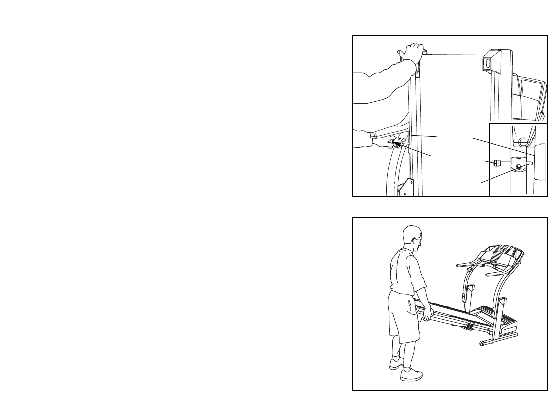
HOW TO LOWER THE TREADMILL FOR USE
1. Hold the upper end of the treadmill with your right hand as
shown. Using your left hand, pull the latch knob to the left
and hold it. Pivot the treadmill down until the frame is past
the latch pin. Slowly release the latch knob.
2. Hold the treadmill firmly with both hands, and lower the tread-
mill to the floor. Do not drop the treadmill frame to the
floor. To decrease the possibility of injury, bend your legs
and keep your back straight.
Frame
Latch Knob
Latch Pin

TROUBLESHOOTING
Most treadmill problems can be solved by following the steps below. Find the symptom that applies, and
follow the steps listed. If further assistance is needed, please call our Customer Service Department.
PROBLEM: The power does not turn on
SOLUTION: a. Make sure that the power cord is plugged into a properly earthed outlet. (See page 8.) If an ex-
tension cord is needed, use only a 3-conductor, 1 mm2(14-gauge) cord that is no longer than 1.5
m (5 ft.). Important: The treadmill is not compatible with GFCI-equipped outlets.
b. After the power cord has been plugged in, make sure that the key is fully inserted into the console.
c. Check the circuit breaker located on the treadmill
near the power cord. If the switch protrudes as
shown, the circuit breaker has tripped. To reset the
circuit breaker, wait for five minutes and then press
the switch back in.
d. Check the on/off switch located on the treadmill near
the power cord. The switch must be in the on position.
PROBLEM: The power turns off during use
SOLUTION: a. Check the circuit breaker located on the treadmill frame near the power cord (see c. above). If
the circuit breaker has tripped, wait for five minutes and then press the switch back in.
b. Make sure that the power cord is plugged in. If the power cord is plugged in, unplug it, wait for
five minutes, and then plug it back in.
c. Remove the key from the console. Reinsert the key fully into the console.
d. Make sure that the on/off switch is in the on position.
e. If the treadmill still will not run, please call our Customer Service Department.
PROBLEM: The console is too high or too low
SOLUTION: a. The height of the console is adjustable. See assembly step 7 on page 8 for instructions.
PROBLEM: The treadmill rocks during use
SOLUTION: a. See HOW TO LEVEL THE TREADMILL on page 26.
29
Tripped
c
Reset
On
Position
d
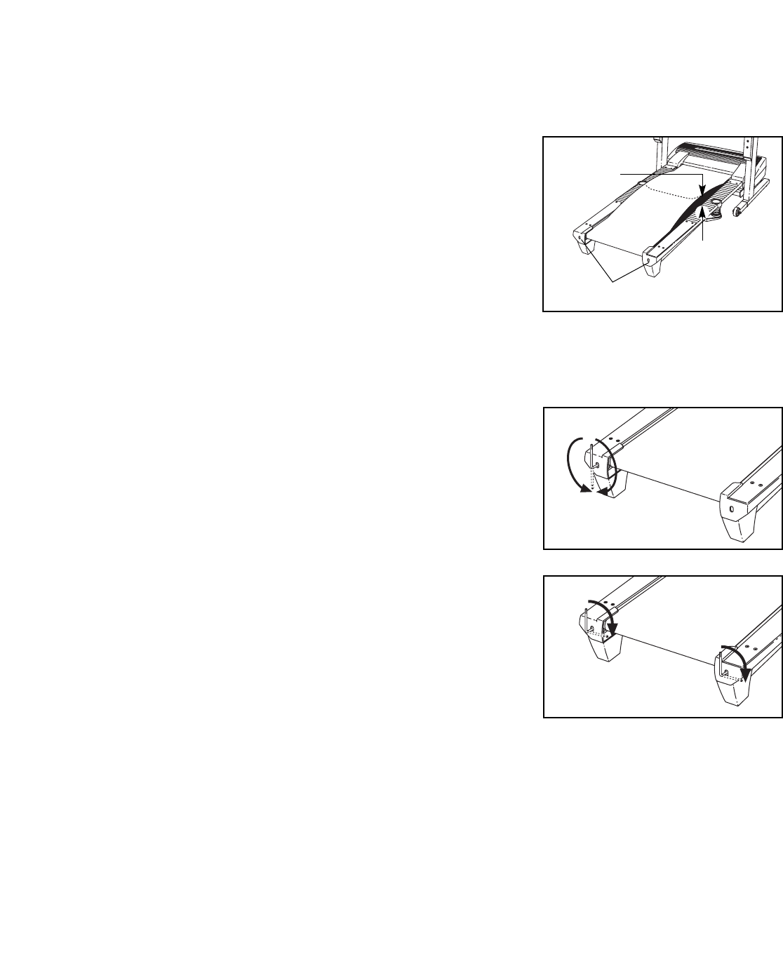
PROBLEM: The walking belt slows when walked on
SOLUTION: a. If an extension cord is needed, use only a 3-conductor, 1mm2(14-gauge) cord that is no longer
than 1.5 m (5 ft.).
b. If the walking belt is overtightened, treadmill perfor-
mance may decrease and the walking belt may be-
come damaged. Remove the key and UNPLUG THE
POWER CORD. Using the hex key, turn both rear roller
adjustment bolts counterclockwise, 1/4 of a turn. When
the walking belt is properly tightened, you should be
able to lift each side of the walking belt 5 to 7 cm (2 to 3
in.) off the walking platform. Be careful to keep the
walking belt centred. Plug in the power cord, insert the
key, and run the treadmill for a few minutes. Repeat
until the walking belt is properly tightened.
c. If the walking belt still slows when walked on, please call our Customer Service Department.
PROBLEM: The walking belt is off-centre or slips when walked on
SOLUTION: a. If the walking belt is off-centre, first remove the key
and UNPLUG THE POWER CORD. If the walking
belt has shifted to the left, use the hex key to turn
the left rear roller bolt clockwise 1/2 of a turn; if the
walking belt has shifted to the right, turn the bolt
counterclockwise 1/2 of a turn. Be careful not to over-
tighten the walking belt. Plug in the power cord, insert
the key, and run the treadmill for a few minutes.
Repeat until the walking belt is centred.
b. If the walking belt slips when walked on, first re-
move the key and UNPLUG THE POWER CORD.
Using the hex key, turn both rear roller bolts clock-
wise, 1/4 of a turn. When the walking belt is correctly
tightened, you should be able to lift each side of the
walking belt 5 to 7 cm (2 to 3 in.) off the walking plat-
form. Be careful to keep the walking belt centred. Plug
in the power cord, insert the key, and carefully walk
on the treadmill for a few minutes. Repeat until the
walking belt is properly tightened.
PROBLEM: The incline of the treadmill does not change correctly
SOLUTION: a. With the key in the console, press one of the Incline buttons. Whilst the incline is changing, re-
move the key. After a few seconds, reinsert the key. The treadmill will automatically rise to the
maximum incline level and then return to the minimum level. This will recalibrate the incline system.
b
a
Rear Roller Adjustment Bolts
5–7 cm
b
30
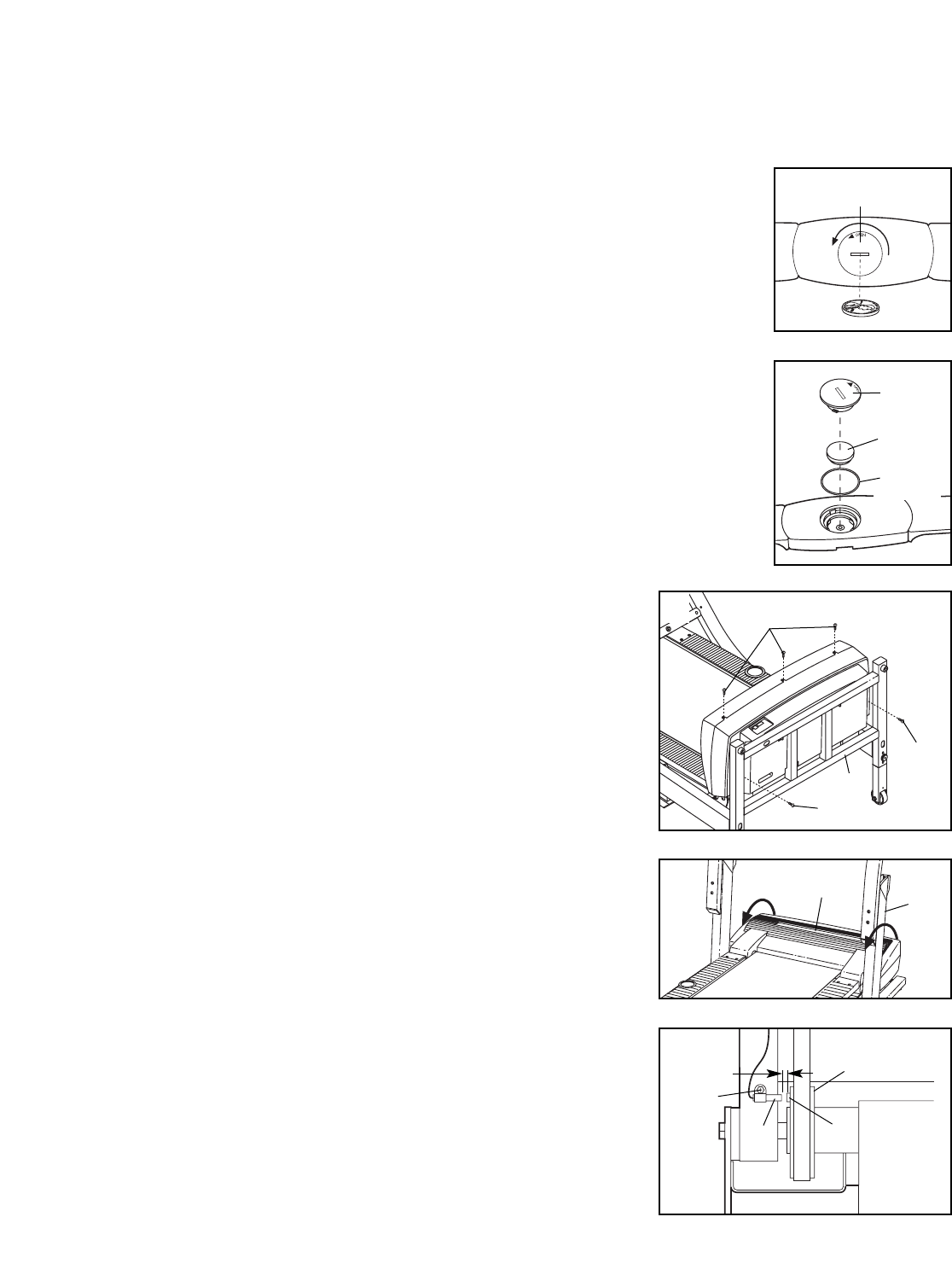
PROBLEM: The chest pulse sensor does not function properly
SOLUTION: a. If the chest pulse sensor does not function properly, see CHEST PULSE SENSOR TROU-
BLESHOOTING on page 9.
b. If the chest pulse sensor still does not function properly, the battery
should be changed. To replace the battery, locate the battery cover
on the back of the sensor unit. Insert a coin into the slot in the cover
and turn the cover counterclockwise to the “open” position. Remove
the cover.
Remove the old battery from the sensor unit. Insert a new CR 2032
battery, making sure that the writing is on top. In addition, make sure
that the rubber gasket is in place in the sensor unit. Replace the bat-
tery cover and turn it to the closed position.
PROBLEM: The displays of the console do not function properly
SOLUTION: a. Remove the key from the console and UNPLUG THE
POWER CORD. With the help of a second person,
carefully tip the Upright Base (97) down as shown.
Remove the five Hood Screws (44). Note: A phillips
screwdriver with at least a 13 cm (5 in.) shaft is re-
quired.
With the help of a second person, carefully raise the
Upright Base (97) as shown. Carefully pivot the Hood
(123) off.
Locate the Reed Switch (22) and the Magnet (19) on
the left side of the Pulley (18). Turn the Pulley until the
Magnet is aligned with the Reed Switch. Make sure
that the gap between the Magnet and the Reed
Switch is about 3 mm (1/8 in.). If necessary, loosen
the Screw (23) and move the Reed Switch slightly.
Retighten the Screw. Reattach the Hood, and run the
treadmill for a few minutes to check for a correct
speed reading.
44
44
44
97
a
31
123 97
Battery
Rubber
Gasket
Battery Cover
b
Battery
Cover
19
23
22
Top
View
3 mm 18
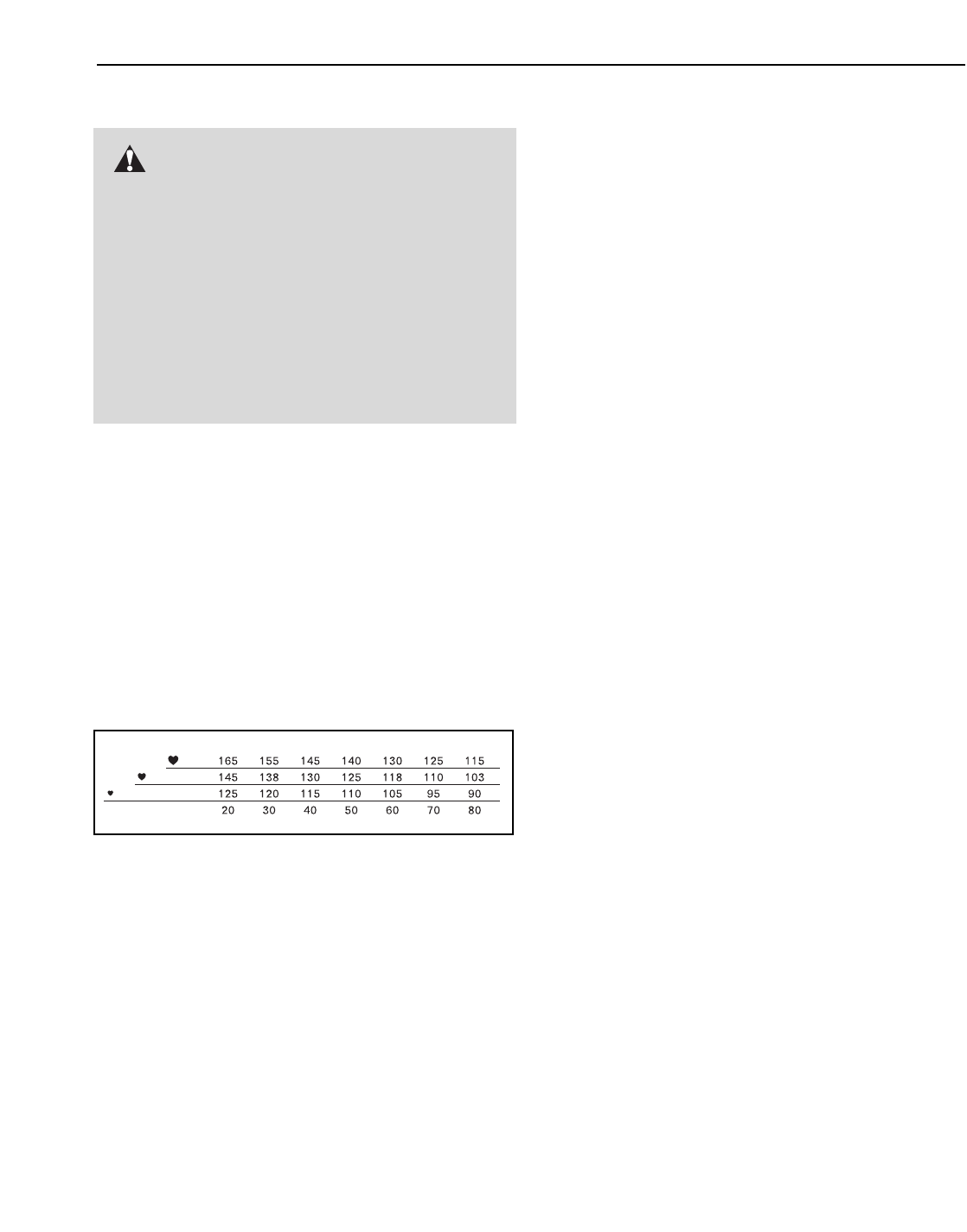
32
CONDITIONING GUIDELINES
The following guidelines will help you to plan your ex-
ercise program. For more detailed exercise informa-
tion, obtain a reputable book or consult your physician.
EXERCISE INTENSITY
Whether your goal is to burn fat or to strengthen your
cardiovascular system, the key to achieving the
desired results is to exercise with the proper intensity.
The proper intensity level can be found by using your
heart rate as a guide. The chart below shows recom-
mended heart rates for fat burning and aerobic exercise.
To find the proper heart rate for you, first find your age
near the bottom of the chart (ages are rounded off to
the nearest ten years). Next, find the three numbers
above your age. The three numbers define your “train-
ing zone.” The lower two numbers are recommended
heart rates for fat burning; the higher number is the
recommended heart rate for aerobic exercise.
To measure your heart rate during exercise, use the
pulse sensor.
Fat Burning
To burn fat effectively, you must exercise at a relatively
low intensity level for a sustained period of time.
During the first few minutes of exercise, your body
uses easily accessible carbohydrate calories for en-
ergy. Only after the first few minutes does your body
begin to use stored fat calories for energy. If your goal
is to burn fat, adjust the speed and incline of the tread-
mill until your heart rate is near the lowest number in
your training zone.
For maximum fat burning, adjust the speed and incline
of the treadmill until your heart rate is near the middle
number in your training zone.
Aerobic Exercise
If your goal is to strengthen your cardiovascular sys-
tem, your exercise must be “aerobic”. Aerobic exercise
is activity that requires large amounts of oxygen for
prolonged periods of time. This increases the demand
on the heart to pump blood to the muscles, and on the
lungs to oxygenate the blood. For aerobic exercise,
adjust the speed and incline of the treadmill until your
heart rate is near the highest number in your training
zone.
WORKOUT GUIDELINES
Each workout should include the following three parts:
A Warm-up—Start each workout with 5 to 10 minutes
of stretching and light exercise. A proper warm-up in-
creases your body temperature, heart rate and circula-
tion in preparation for exercise.
Training Zone Exercise—After warming up, increase
the intensity of your exercise until your pulse is in your
training zone for 20 to 60 minutes. (During the first few
weeks of your exercise program, do not keep your
pulse in your training zone for longer than 20 minutes.)
Breathe regularly and deeply as you exercise—never
hold your breath.
A Cool-down—Finish each workout with 5 to 10 min-
utes of stretching to cool down. This will increase the
flexibility of your muscles and will help prevent post-
exercise problems.
EXERCISE FREQUENCY
To maintain or improve your condition, complete three
workouts each week, with at least one day of rest be-
tween workouts. After a few months, you may com-
plete up to five workouts each week if desired. The key
to success is to make exercise a regular and enjoyable
part of your everyday life.
WARNING: Before beginning this
or any exercise program, consult your physi-
cian. This is especially important for individu-
als over the age of 35 or individuals with pre-
existing health problems.
The pulse sensors are not medical devices.
Various factors, including the user’s move-
ment, may affect the accuracy of heart rate
readings. The pulse sensors are intended only
as exercise aids in determining heart rate
trends in general.
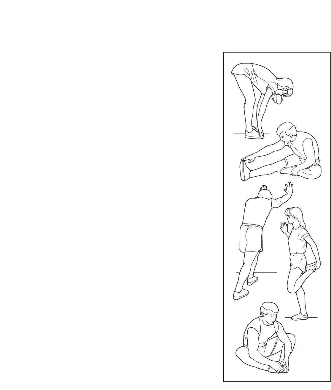
33
SUGGESTED STRETCHES
The correct form for several basic stretches is shown at the right. Move slowly as you stretch—never bounce.
1. Toe Touch Stretch
Stand with your knees bent slightly and slowly bend forward from
your hips. Allow your back and shoulders to relax as you reach
down toward your toes as far as possible. Hold for 15 counts, then
relax. Repeat 3 times. Stretches: Hamstrings, back of knees and
back.
2. Hamstring Stretch
Sit with one leg extended. Bring the sole of the opposite foot toward
you and rest it against the inner thigh of your extended leg. Reach
toward your toes as far as possible. Hold for 15 counts, then relax.
Repeat 3 times for each leg. Stretches: Hamstrings, lower back and
groin.
3. Calf/Achilles Stretch
With one leg in front of the other, reach forward and place your
hands against a wall. Keep your back leg straight and your back
foot flat on the floor. Bend your front leg, lean forward and move
your hips toward the wall. Hold for 15 counts, then relax. Repeat 3
times for each leg. To cause further stretching of the achilles ten-
dons, bend your back leg as well. Stretches: Calves, achilles ten-
dons and ankles.
4. Quadriceps Stretch
With one hand against a wall for balance, reach back and grasp
one foot with your other hand. Bring your heel as close to your but-
tocks as possible. Hold for 15 counts, then relax. Repeat 3 times for
each leg. Stretches: Quadriceps and hip muscles.
5. Inner Thigh Stretch
Sit with the soles of your feet together and your knees outward. Pull
your feet toward your groin area as far as possible. Hold for 15
counts, then relax. Repeat 3 times. Stretches: Quadriceps and hip
muscles.
1
2
3
4
5

34
PART LIST—Model No. PETL78132 R0604A
Key No. Qty. Description Key No. Qty. Description
1 1 Left Foot Rail
2 12 Foot Rail Screw
3 2 Isolator Bolt (Top)
4 2 Isolator Decal
5 2 Isolator Top Cap
6 2 Gray Isolator Spring
7 2 Isolator
8 2 Isolator Bottom Cap
9 2 Isolator Bracket Cover
10 2 Isolator Bracket
11 4 Isolator Bracket Bolt
12 2 Isolator Bolt
13 1 Walking Platform
14 2 Belt Guide
15 4 Belt Guide Screw
16 2 Walking Platform Screw (Rear)
17 2 Frame Pivot Bolt
18 1 Front Roller/Pulley
19 1 Magnet
20 9 Pivot Nut
21 2 Pivot Bushing
22 1 Reed Switch
23 1 Reed Switch Screw
24 1 Reed Switch Clip
25 2 Lift Pivot Bolt
26 2 Motor Washer
27 1 Pulley/Flywheel/Fan
28 1 Motor Pulley
29* 1 Idler Arm Assembly
30 1 Idler Arm Pivot Bolt
31 1 Motor
32 1 Idler Arm
33 1 Lift Frame
34 1 Motor Pivot Nut
35 2 Walking Platform Nut
36 1 Idler Pivot Washer
37 1 Incline Motor
38 4 Incline Motor Bolt
39 2 1/4” Washer
40 1 Roller Star Washer
41 1 Front Roller Adj. Bolt
42 2 Walking Platform Screw (Front)
43 1 Transformer
44 3 Hood Screw
45 1 Hood Cover
46 1 Hood Decal
47 1 Circuit Breaker
48 1 Controller
49 2 Power Cord
50 1 Receptical
51 2 Static Decal
52 10 3/4” Tek Screw
53 1 Belly Pan Clip
54 1 Belly Pan
55 1 Releasable Tie
56 1 Clamp Screw
57 1 Tie Holder Clamp
58 1 Cable Tie
59 1 Frame
60 1 Right Rear Foot
61 1 Chest Pulse Strap
62 2 Rear Roller Adj, Bolt
63 1 Rear Roller
64 1 Hex Key
65 1 5/32” Hex Key
66 1 Left Rear Foot
67 1 Right Foot Rail
68 1 Walking Belt
69 2 Warning Decal
70 2 Blue Isolator Spring
71 1 Pulse Bar
72 4 Pulse Bar Screw
73 1 Splitter
74 1 Wire Harness
75 1 Right Top Endcap
76 4 Console Bolt
77 4 Internal Star Washer
78 5 Hood Cover Screw
79 2 Upright Spacer
80 1 Right Upright
81 1 Left Top Endcap
82 1 Latch Assembly
83 1 Controller Wire
84 1 Left Upright
85 2 CD Holder
86 4 Upright Bolt
87 8 U-Nut
88 2 Upright Endcap (Lower)
89* 2 Extension Leg Assembly
90 2 Wheel Bolt
91 2 Warning Decal
92 2 Extension Leg
93 1 Small Nut
94 2 Wheel
95 2 Levelling Foot
96 4 Extension Leg Bolt
97 1 Upright Base
98 1 Photo Switch
99 2 Base Pad
100 2 Upright Base Endcap
To locate the parts listed below, see the EXPLODED DRAWING attached in the centre of this manual.

35
Key No. Qty. Description Key No. Qty. Description
101 1 Console Base
102 2 Lift Frame Pivot Nut
103 8 Ground Screw/Choke Screw
104 1 Key Clip
105 2 Fan Screw
106 1 Fan
107 1 Console
108 44 Screw
109 1 Left Tray
110 1 CD Console
111 1 Right Tray
112 1 iFIT.com Audio Cable
113 1 iFIT.com Jack
114 2 Motor Bolt
115 1 Photo Switch Screw
116 1 Console Base Frame
117 1 Left Handgrip (Top)
118 1 Photo Switch Nut
119 1 Left Bottom Handgrip
120 1 Right Handgrip (Top)
121 1 Right Bottom Handgrip
122 1 Access Door
123 1 Hood
124 1 Console Back
125 1 Photo Switch Star Washer
126 2 Rear Roller Star Washer
127 4 Upright Star Washer
128 2 Front Isolator
129 2 Front Isolator Screw
130 1 Optic Disk
131 1 iFIT.com Wire
132 1 Filter Wire
133 1 Photo Switch Wire
134 2 Latch Screw
135 2 1” Tek Screw
136 1 Pulley Nut
137 1 Pulley Washer
138 1 Idler Pulley
139 1 Chest Pulse Monitor
140 1 Pulley Bolt
141 3 Ferrite Box
142 1 Filter
143 4 Plastic Standoff
144 1 Electronics Bracket
145 1 Power Board
146 1 Choke
147 1 Controller Bracket
148 1 Motor Isolator
149 1 Pulse Receiver
150 1 On/Off Switch
151 1 Circuit Breaker
152 1 Edge Guard
153 1 Pulse Wire
154 1 UK Adaptor
# 1 8” Green Wire, F/Ring
# 1 8” Green Wire, 2 Ring
# 1 14” White Wire, 2F
# 1 6” White Wire, 2F
# 1 6” Blue Wire, 2F
# 1 4” Blue Wire, 2F
# 1 4” Black Wire, 2F
# 1 User’s Manual
*Includes all parts shown in the box
#These parts are not illustrated
Specifications are subject to change without notice.

Part No. 209731 R0604A Printed in Canada © 2004 ICON IP, Inc.
ORDERING REPLACEMENT PARTS
To order replacement parts, contact the ICON Health & Fitness Ltd. office, or write:
ICON Health & Fitness, Ltd.
Customer Service Department
Unit 4, Revie Road Industrial Estate
Revie Road
Beeston
Leeds, LS118JG
UK
Tel:
Outside the UK: 0 (044) 113 387 7133
Fax: 0 (044) 113 387 7125
To help us assist you, please be prepared to give the following information:
• The MODEL NUMBER of the product (PETL78132)
• The NAME of the product (PROFORM®790 TR treadmill)
• The SERIAL NUMBER of the product (see the front cover of this manual)
• The KEY NUMBER AND DESCRIPTION OF THE PART(S) (see the PART LIST on pages 34 and 35 and the
EXPLODED DRAWING attached in the centre of this manual)
08457 089 009
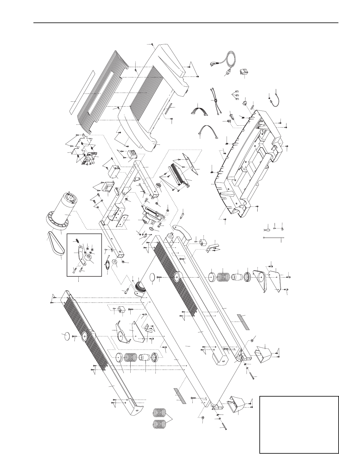
2
4
3
2
9
2
1
10
11
12
42
11
15
14
69 13
16
17
18
19
4
3
2
2
2
16
63
62
39
66
68
52
65 64
62
39
52
60
11
11
10
9
14
15
59
67
42
17
20
20
38
21
37
38 33
103
20
23
20
21
22 24
43
55
56
57
58
44
52
54
53
52
52
52
51
78
123
45
44
46
49
50
78
8
7
5
6
8
7
6
5
41
40
39
12
93
131
83
133
132
130
115
125
98
118
126
126
35
35
129
128
129
128
44
78
69
70
26
114
148
29*
32
137
34
136
138
20
140
30
36
48
53
53
147
103
103
31
27
28 103
146
145
143
143
144
103
142
141
103
150
151
152
44
44
154
EXPLODED DRAWING—Model No. PETL78132 R0604A
To identify parts shown
on this EXPLODED
DRAWING, see the
PART LIST on pages
34 and 35 of the user’s
manual.
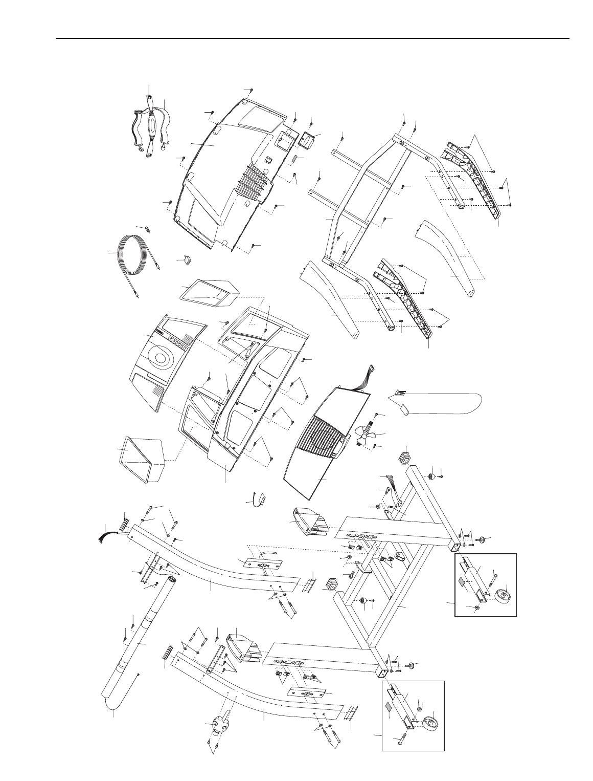
112
113
86
84
134
82
88
79
97
89*
90
94
20
91
92
95
96
89*
20
94
90
91
92
95
96
87
85
86
80
79
88
81
76
85
72
72
77
153
71
99
135
87
100
25 20
20
25 75
103
87
87
99
135
104
105
106
105
107 117
120
116
119
108
108
108 108
121
108
108
108 108
108
108
108
108
108
108
108
108
108
108
108
108
108
108
108
124
111
110
108
108
108
108
108
108
108
108
101
109
74
75
77
103
72
72
76
100
51
122
72
72
72
39
39
127
127
44
44
79
139
61
149
73
EXPLODED DRAWING—Model No. PETL78132 R0604A

Цвет на изображении может
отличаться от действительного рисунка.
Средняя цена в магазинах не определена.
- Характеристики
- Описание
- Отзывы
- Где купить?
Технические характеристики Электрическая беговая дорожка ProForm 790 TR (PETL78132)
Общие характеристики |
|
|---|---|
| Производитель | ProForm |
| Тип | электрическая |
| Конструкция | складная |
| Максимальный вес пользователя | 125 кг |
| Размеры бегового полотна | 48×140 см |
Техническая информация |
|
| Двигатель | 2.5 л.с. |
| Скорость движения бегового полотна | до 19 км/ч |
| Регулировка угла наклона | автоматическая (плавная), максимальный угол наклона 10.8 град. |
| Измерение пульса | есть, крепление на грудь, на ручке |
Программы |
|
| Количество программ тренировки | 12 |
| Количество пульсозависимых программ | 4 |
| Встроенные программы | фитнес-оценка, пользовательская |
| Показания дисплея | пройденное расстояние, расход калорий, текущая скорость, темп, угол наклона, измерение пульса |
Дополнительная информация |
|
| Встроенные устройства | вентилятор |
| Особенности конструкции | транспортировочные ролики/колеса, система амортизации |
| Размеры (ШxВxД): | 90 х 140 х 170 см |
| Вес | 95 кг |
| Особенности | встроенный CD-плеер |
Полная информация о товаре, изготовителе, комплектации, технических характеристиках и функциях содержится в технической документации.
Описание товара
Отзывы о Электрическая беговая дорожка ProForm 790 TR (PETL78132)
Отзывов на данную модификацию пока нет. Ваш отзыв поможет кому-то сделать выбор. Спасибо, что делитесь опытом!
Лучшие варианты покупки по низкой цене
Где купить дёшево? Рассмотрите предложения с доставкой или самовывозом. Сравнение цен онлайн. Выберите удобное для себя место приобретения.
Возможно, вас также заинтересует, что с этим товаром часто покупают
6 из 4007 товаров в категории «Беговые дорожки»
Электрическая беговая дорожка ProForm 790 TR (PETL78132): стоит ли покупать, описание, фото, характеристики, отзывы покупателей, инструкция и аксессуары, сборка аппарата, обзор.
More products and manuals for Treadmills ProForm
| Models | Document Type |
|---|---|
|
5.0 Crosstrainer Treadmill |
User Manual
28 pages |
|
Trainer 30464.0 |
User Manual
28 pages |
|
e35s PFTL69711 |
User Manual
31 pages |
|
PFTL66906.0 |
User Manual
28 pages |
|
515tr Treadmill |
User Manual
28 pages |
|
TREADMILL PFTL79101 |
User Manual
26 pages |
|
610 Tr Treadmill |
User Manual
28 pages |
|
TREADMILL PFTL81405.0 |
User Manual
36 pages |
|
605 Cs Treadmill |
User Manual
32 pages |
|
831.299581 |
User Manual
27 pages |
|
PFTL63105.2 |
User Manual
26 pages |
|
TREADMILL PATL30706.0 |
User Manual
30 pages |
|
831.293062 |
User Manual
30 pages |
|
695 Pi Treadmill |
User Manual
26 pages |
|
475 Audio Series Treadmill |
User Manual
31 pages |
|
STYLE 8000 |
User Manual
28 pages |
|
505s |
User Manual
10 pages |
|
831.29523.4 |
User Manual
22 pages |
|
Crosswalk 831.297231 |
Owner’s Manual
16 pages |
|
PFTLIO040 |
Owner’s Manual
16 pages |
