-
Contents
-
Table of Contents
-
Bookmarks
Quick Links
Wired Controller
YR-E17
CONTENT
Parts And Functions…………………………………………………… 1
Operation …………………………………………………………………. 9
• Please read this operation manual before using the air conditioner.
• Please keep this manual carefully and safely.
Related Manuals for Haier YR-E17
Summary of Contents for Haier YR-E17
-
Page 1
Wired Controller Operation & Installation Manual YR-E17 CONTENT Parts and Functions…………1 Operation …………….9 Wired Controller Wiring Instruction ……..46 • Please read this operation manual before using the air conditioner. • Please keep this manual carefully and safely. -
Page 2: Parts And Functions
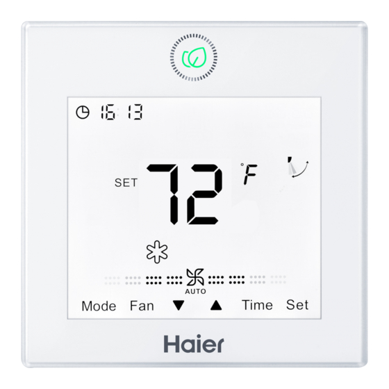
Parts and Functions Interface Display…
-
Page 3
Parts and Functions ON/OFF Adjusting key for temperature, clock, timer, sleeping adjustment, temp. compensation and energy saving; Inquiring key for detail parameter and malfunction inquiry; Switching key for function switch. The adjusting accuracy of temperature is 0.5°C (1°F). If energy saving mode is not set, the adjusting range is from 16°C (60°F) to 30°C (86°F). -
Page 4
Parts and Functions • If using Fresh Air unit, set temp. cannot be adjusted. If there is no Central/Lock set, the temp. will be fixed at 18°C (64°F) in cooling and 22°C (72°F) in heating. The Up/Down key will not display in normal state, but will display and valid in timer setting, function selection, unit shift in malfunction inquiry, parameter shift in parameter check, unit No. -
Page 5
Parts and Functions Pressing this key, fan speed will be changed in sequence as follows: (Low) → (Medium) → (High)→ ( Auto) → (Low) Note: Auto fan will be changed in sequence as follows: → → → Pressing this key, fan speed will be changed in sequence as follows (Only valid for parts of models): (Breeze) → … -
Page 6
Parts and Functions Note: If using Fresh Air unit, fan will be in auto fan and cannot be adjusted. If press FAN key, fan icon and FFFF on the top-right corner will flash, prompting fan speed cannot be adjusted, and will statically display after 3s. Fresh Air unit fan speed will be controlled automatically by indoor unit and wired controller will always display auto fan. -
Page 7
Parts and Functions 2.Press to select the functions in sequence as follows: health airflow down (Only valid for part of models) → health airflow up (Only valid for part of models) →10°C heating function (this function only works in the heating mode, only valid for part of models) → (motion sensing,only valid for part of models) → (the second 8 of 88.8 in the temp. display area displaying B,only valid for part of models) → (the second 8 of 88.8 in the temp. display area displaying A,only valid for part of models) → … -
Page 8
Parts and Functions Icon Clock; Parameter setting/inquiry; Malfunction display; Mode setting. Timer ON/OFF: Sleeping; Parameter setting/ inquiry; Malfunction display. ROOM/SET temp. and humidity display, each step is 0.5°C (1°F) . For example, if the temp. is 25°C (77°F), it will display 25.0°C (77°F). Humidity display function is reserved. Energy Saving, This icon will be displayed only when energy saving function is set. -
Page 9
Parts and Functions Sleeping. This icon is displayed when setting the sleeping, and left time of sleeping is displayed by Heat Reclaim Ventilation, This icon is displayed when setting the heat reclaim ventilation. Electrical Heating. This icon will display when electrical heating is set on DC wired controller. -
Page 10
Operation Dip Switch Interpretation (for AC) On/Off Default Function switch station setting Slave wired controller Master wired controller Ambient temp. display on Ambient temp. display off Collect ambient temp. from PCB of indoor Collect ambient Temp. from wired controller Non-volatile memory invalid Non-volatile memory valid Old protocol Selfadaption… -
Page 11
Operation Difference between the Function of the Master Wired Controller and Slave Wired Controller Master Comparison wired Slave wired controller item controller 1. ON/OFF, Mode, Fan Speed, Temp. Setting, Swing, Energy Saving, Clock function, Heat Reclaim Ventilation functions function, Mode Setting, Screen Function Saving and Child Lock are available available… -
Page 12
Operation (2) If the wired controller can’t be communicated with the indoor PCB normally after powering on, the initialization will be finished in 4 minutes, and then the communication malfunction can be checked from the malfunction inquiry function. Screen Saving (1) In the state of off and non screen saving, keep pressing for 5s to set screen saving time, which will be shown after the top-right colon 88 statically. -
Page 13
Operation Clock Function (1) 24-hour system is used, and at first time of powering on, it will display default 12:00. (2) When first powering on wired controller, will be displayed on the wired controller interface, clock time can be adjusted within 10s. At the same time, clock icon minute-place of time will flash, meaning the current time can be adjusted. Press Up/Down key to adjust minute-place with flashing of clock icon and no flashing of minute-place. Press … -
Page 14
Operation (3) Press Time key for 5s to enter clock setting function. It will show after first powering on (if not first time of powering on, clock time is the memorized time), with clock icon and minute-place flashing, meaning current time can be adjusted. Press Up/Down key to adjust minute-place with flashing of clock icon and no flashing of minute-place. Press Time key to shift to hour-place, and then press Up/Down key to adjust hour-place with flashing of clock … -
Page 15: Timer Function
Operation (7) When setting timer or sleeping function, clock time cannot be adjusted. If press Time key for 5s to enter clock adjustment, clock icon and clock time will flash indicating time cannot be adjusted. Timer Function (1) Timer mode setting: Timer ON, Timer OFF, Timer ON/OFF. (2) Default: Timer ON is , Timer OFF is (3) Precision: The time precision is 1 minute.
-
Page 16
Operation Then hour position and “ON” are flashing. Press adjust the timer, minus/add 1 hour a time. Keep pressing to accelerate the adjusting speed. Press key a second time and then the minute position and “ON” are flashing. Press to confirm the setting, the setting time is displayed and “ON” will not flash. If there is no input for 10s, this setting will be cancelled and the timer will come back to the previous state. Timer OFF: Press key, it displays default for the first time … -
Page 17
Operation Then hour position and “ON” are flashing; Press again, the minute position and “ON” are flashing; Press key again, it displays default for the first time (previous setting will be displayed if there is setting before). Then the hour position and “OFF” are flashing; Press key again, the minute position and “OFF” are flashing; Press key again, it displays default for the first time (previous setting will be displayed if there is setting before). Then the hour position and “ON” are flashing. Press adjust the timer, minus/add 1 hour a time. Keep pressing to accelerate the adjusting speed;… -
Page 18
Operation Timer Setting Cancellation (1) If there is no Time key related operation for 10s, this setting will be cancelled and the timer will come back to the previous state. (2) Sequence: Pressing once, it displays default for the first time (previous setting will be displayed if there is setting before). The hour position and “ON” are flashing;… -
Page 19
Operation Pressing a 8th time, the minute position and “OFF” are flashing; Pressing a 9th time, cancel the setting. (3) Relation to other buttons when timer is set. Press the key or key to exit the current setting, press them again to operate the function accordingly; Press (ON/OFF) key can exit the timer setting and power … -
Page 20
Operation ② If Sw7 is on: Up/Down swing and Left/Right swing are available. Press SET key to enter function circulation, Left/Right swing icon flashing, then press Up/Down key to enter Up/Down swing, with Up/Down swing icon flashing. Press SET key again when swing icon flashing to confirm, with swing icon statically display. If swing function is set, execute the above operation to cancel. ③ If connecting to the salve wired controller, Sw7 dip code of master and slave wired controllers should be set the same and should match the actual wired controller unit. -
Page 21
Operation ① If the angle of the Up/Down swing can be adjusted: Press SET key to enter the function circulation; the Up/Down swing icon will flash. Press the SET key again; the swing angle will flash(if powered on for the first time, default angle will be different according to different modes; if not for the first time, the angle of swing will be displayed as last time). At this time, swing angle can be adjusted by Up/Down key (when in intelligent mode, the swing angle is position 1,press up key to automatic swing, and press down key to position 2).When pressing Up/Down key to adjust angle, If no operation in 10s,… -
Page 22
Operation (4) Pressing Fan key or Mode key can both exit swing function, with no order sending. When Fan or Mode key is pressed again, the order will be sent. If the present angle is confirmed, pressing SET key will exit the swing function. In the adjustment process, if there is no key pressed for 10s, swing function will be exited, and swing angle will execute the final adjusted angle. In the adjustment process, pressing the ON/OFF key to power off the wired controller directly, and swing angle is the final adjusted swing angle. -
Page 23
Operation Health airflow up/down function (Only valid for part of models) (1) The function can be set through wired controller or remote controller. (2) The function circulation is as follows: (Only when Left/Right swing is valid) → (Only when Up/ Down swing is valid)→ → (ventilation function)→ (reserved function)→ (When it’s time for filter cleaning, this icon will involve in circulation) → (the second 8 of 88.8 in the temp. display area displaying A,only valid for part of models)→ … -
Page 24
Operation (6) After the function is set, the angle of Up/Down or Left/Right swing can be normally adjusted in the main interface. Press the SET key to enter function circulation. When Up/Down swing icon flashes, press SET key, and then swing angle position 1 will flash. Press Up/Down key to adjust the angle. When the adjusted swing angle is executed, the health airflow up/down is canceled simultaneously. Sleeping (1) Press key to enter function setting, press to the… -
Page 25
Operation (4) In sleeping set or modification state, if there is no operation in 10 seconds, it will keep previous state, and the setting or modification is invalid this time. (5) Under sleeping and timer setting state, it will display setting time respectively; when setting simultaneously, it will display the prior executed time. When timer off is executed first, sleeping function will be cancelled and when sleeping is executed first, then timer off function will be operated after that. (6) Under function setting state, it will exit function setting state by pressing key. -
Page 26
Operation Heat Reclaim Ventilation Function (1) Press key to enter function setting, press to the heat reclaim ventilation icon “ ” and it will flash, press key again to confirm the operation. The above operation can cancel the heat reclaim ventilation function if heat reclaim ventilation function has been set. (2) After setting heat reclaim ventilation function, it is switched off together with off commend from wired controller. -
Page 27
Operation (2) If the current temp. is displayed in Fahrenheit,set temp. should be adjusted to 60°F in each mode(when energy saving function is set currently, the cooling/dry mode will be the lowest limit value of the energy saving function). Then press key for 15s to switch to Celsius, the interface will display 16°C (when energy saving function is set, its lowest limit value of Celsius will be displayed). -
Page 28: Energy Saving
Operation Energy Saving (1) Press key to enter function setting, then press to choose energy saving, press key again to confirm the operation and display energy saving icon . If energy saving function has been set, the above operation will cancel (2)The energy saving default parameter are 23°C (74°F) (the lowest temp.
-
Page 29
Operation 10°C Heating Function (Only valid for part of models) (1) Only in heating mode, this function is valid in function circulation. (2) For the four-way cassette model, press the SET key for 5s to enter the function circulation. When it switches to the 10°C heating function, 10°C will flash in the temp. display … -
Page 30
Operation (5) If it’s not the four-way cassette model, press the Set key once to enter the function circulation. When it switches to the 10°C heating function, the temp. display area will statically display 10°C. Then press the Set key to confirm. The exist operations will be the same as the four-way cassette model. (6) This function can be remembered when it is turned on/off. -
Page 31
Operation (2) The circulation of the wind deflector: four-way cassette deflectors controlled together→four-way cassette deflector 1→four-way cassette deflector 2→four-way cassette deflector 3→four-way cassette deflector 4→four-way cassette deflectors controlled together. (3) If it’s not the first time to enter it, press Set key, the wind deflector set last time will flash. Meanwhile the angle of this deflector set last time will be displayed statically, and the number of the wind deflectors next to Up/Down swing will be statically displayed. (4) Press Set key to choose the wind deflector, and the selected one will flash. At this time press Up/Down key to adjust the angle of the wind deflector. The wind deflector will keep flashing when adjusting. After finishing adjusting for 5s, the wind deflector will be displayed statically, meaning existing the angle adjustment. At this time press Up/Down key to adjust the temp.. Pressing mode key or Fan key during the adjustment will exist the adjustment of four-way cassette function. The position and angle of the wind deflector will be set the same as last time. If no pressing Up/Down key for 5s after Set key pressed, the selected wind deflector will stop … -
Page 32
Operation Motion sensing (Only valid for part of models) (1) Press Set key for 5s to enter the function circulation, and then press Up/Down key to switch to (the second 8 of 88.8 in the temp. display area displaying A) → (the second 8 of 88.8 in the temp. display area displaying B) → (motion sensing). (2) ①… -
Page 33
Operation Mode Setting (Only valid for part of models) (1) In off and non screen saving state, press Mode key for 5s, it will display 8 segment on the top-left corner of current mode circulation, default value being 0. Press Up/Down key to shift between 0, 1, 2, 3, then press Set key to confirm value. It will … -
Page 34
Operation (6) The mode of indoor units can be inquired /changed by the advanced setting function after the wired controller is powered on, Only valid for part of models. (7) Set as follows (Only valid for part of models): Press Set key and Up key for 5s to enter the advanced setting state, with the function A in temp. -
Page 35
Operation Malfunction Display (1) The main interface does not display malfunction. (2) Under no screen saving state, press key for 10 seconds to check all indoor units malfunction in the group, but at this time, the interface does not display clock information and timer information. -
Page 36: Child Lock
Operation Child Lock (1) Child lock function can be used to prevent false operation. All of keys are locked after pressing together for 5 seconds. child lock icon will display on the interface. All of settings will exit and keep the previous state. All of keys are invalid including «ON/OFF». (2) The screen will unlock after pressing together for 5 seconds, child lock icon will disappear and all keys are available.
-
Page 37
Operation Parameter Inquiry (1) Keep pressing for 5 seconds (if it is the four-way cassette model, the time is 10 seconds) to enter parameter inquiry. Unit No. is displayed on 88 area of clock while data type is displayed on 88 area of timer. Unit No. is displayed on the first two »88″ fields of clock while data type is displayed on … -
Page 38
Operation (2) In parameter inquiry state, press key to change the unit No. address in the group. (3) In parameter inquiry state, press the key again or have no operation for 10 seconds to exit. (4) In parameter inquiry state, press can exit the parameter inquiry and press above keys again, their corresponding functions will work. -
Page 39
Operation Unit No. Setting (1) Entering: Press key for 10 seconds (if it is the four- way cassette model, the time is 15 seconds) to enter unit No. setting/ inquiring. (2) Setting is available when the communication address between indoor and outdoor unit is flashing if the indoor unit’s dip switch can set the address, then use to adjust within the range of 0-3F. -
Page 40
Operation Static Pressure Grade Inquiry and Adjustment Function (1) In the state of ON and non screen saving state, press Fan + Set keys for 5s to enter static pressure grade adjustment state with static pressure icon flashing and current static pressure grade statically displaying. Press key to change static pressure grade, then press Set key to confirm. … -
Page 41
Operation (8) The number about the static pressure grade and the static pressure grade can also be queried/ changed by advanced setting interface(Only valid for part of models). Rated Operation Function (Only valid for part of models) (1) Press the SET key and key for 5s to enter the advanced setting interface to inquire/adjust rated operation function. -
Page 42
Operation (3) Rated operation including USA rated operation and European rated operation can be inquired/adjusted through function code 07 in the advanced setting. “00” means the European rated operation, and “01” means the USA rated operation. (4) If the content of 07 is “00”, then press the Up/Down key to switch to 08(Europe rated operation) directly, “09”… -
Page 43
Operation Communication with Central Controller (1) The controller displays to show central control mode after receiving central control signal from indoor unit; (2) When statically displays, all keys except “ON/OFF” of wired controller are invalid. central icon will disappear if no central control signal from indoor unit. (3) When receiving locking signal from indoor unit, statically display, all keys are invalid. -
Page 44
Operation 2) Under heating mode 16°C (60°F), keep pressing for 5 seconds to set energy saving parameter in heating mode. This heating energy saving parameter is flashing behind top- right colon. The default value is 26°C (78°F). This highest target heating temperature can be adjusted by . After setting, press key to confirm and exit. -
Page 45
Operation Communication Malfunction of Wired Controller If there is no communication between wired controller and indoor unit for 4 minutes, it will display error code “07” when checking malfunction. Sensor Malfunction If the dip switch is set to collect ambient Temp. from wired controller and the sensor can’t work normally, it will display error code “01”… -
Page 46
Operation Forced Cooling/ Heating (1) Powered off in cooling mode, keep pressing “ON/OFF” key for 10 seconds, it will enter into the forced cooling function, and the cooling mode icon will be displayed on the interface. “LL” is flashing in the temp. area at the same time. Press “ON/ OFF” key to power off and exit forced cooling. (2) Powered off in heating mode, keep pressing “ON/OFF” key for 10 seconds, it will enter into the forced heating function, and the heating mode icon will be displayed on the interface, “HH” is flashing in the temp. area at the same time. Press “ON/… -
Page 47
Wired Controller Wiring Instruction Wiring Connections of Wire Controller Indoor 1 Indoor 2 Indoor N Indoor 15 Indoor 16 (master unit) Wire controller Wire controller Wire controller Wire controller Wire controller Indoor 1 Indoor 1 Control wiring of wire Wire controller Wire controller controller, polar. -
Page 48
Wired Controller Wiring Instruction C. Two wired controllers control one indoor unit. The wired controller connected with indoor unit is called master one, the other is called slave one. Master wired controller and indoor unit; master and slave wire controllers are all connected through 3 pieces of polar wire. -
Page 49
Wired Controller Wiring Instruction 1. First, put communication wire through the hole in the back cover. Press this button to open the back cover of the wired controller. 2. Fix back cover to the holder. After that, connect communication wire to CON1 port of wired controller. Finally put the front cover of wired controller to back cover to complete the installation. -
Page 50
Wired Controller Wiring Instruction CON1…
Parts and Functions
• If using Fresh Air unit, set temp. cannot be adjusted. If there
is no Central/Lock set, the temp. will be fixed at 18°C (64°F)
in cooling and 22°C (72°F) in heating. The Up/Down key will
not display in normal state, but will display and valid in timer
setting, function selection, unit shift in malfunction inquiry,
parameter shift in parameter check, unit No. setting, sleeping
time adjustment, etc.
24-hour, press
once to minus one minute. Keep pressing,
minus 2 minutes in 1 second’s pressing, then 10 minutes
in 5 seconds. The time will keep decreasing at the pace of
10 minutes a time in 10 seconds. Vice-versa. Press
to
confirm or it will turn back to the previous state automatically in
10s.
Press this key to execute mode switch. For detailed
information, please refer to mode setting.
Note: If using Fresh Air unit, default 3 modes will circulate from
cooling→heating→fan→cooling.
3
Specifications:1015/1015303-yre17.pdf file (01 Apr 2023) |
Accompanying Data:
Haier YR-E17 Remote Control PDF Operation & Installation Manual (Updated: Saturday 1st of April 2023 09:20:32 PM)
Rating: 4.9 (rated by 52 users)
Compatible devices: YR-HQ, YR-H71, 21F7A-P, YR-HD, 21T6B-TD, BH2004D, HTR-D51, DTA-1496.
Recommended Documentation:
Operation & Installation Manual (Text Version):
(Ocr-Read Summary of Contents of some pages of the Haier YR-E17 Document (Main Content), UPD: 01 April 2023)
-
29, 28 Operation (1) Only in heating mode, this function is valid in function circulation. (2) For the four-way cassette model, press the SET key for 5s to enter the function circulation. When it switches to the 10°C heating function, 10°C will ash in the temp. display area. Press the S…
-
25, Haier YR-E17 24 Operation (4) In sleeping set or modication state, if there is no operation in 10 seconds, it will keep previous state, and the setting or modication is invalid this time. (5) Under sleeping and timer setting state, it will display setting time respectively; when setting si…
-
46, 45 Operation (1) Powered off in cooling mode, keep pressing “ON/OFF” key for 10 seconds, it will enter into the forced cooling function, and the cooling mode icon will be displayed on the interface. “LL” is ashing in the temp. area at the same time. Press “ON/ OFF” key to�…
-
11, 10 (1)The wired controller will display all the icons after powering on or reset, then get into the initializing process. The controller will display in sequence as follows: (the top-left corner) → (the top-right corner) → → (the top-left corner), the green LED …
-
7, 6 2.Press to select the functions in sequence as follows: health airow down (Only valid for part of models) → health airow up (Only valid for part of models) →10°C heating function (this function only works in the heating mode, only valid …
-
20, Haier YR-E17 19 ② If Sw7 is on: Up/Down swing and Left/Right swing are available. Press SET key to enter function circulation, Left/Right swing icon ashing, then press Up/Down key to enter Up/Down swing, with Up/Down swing icon ashing. Press SET key again when swing�…
-
Haier YR-E17 User Manual
-
Haier YR-E17 User Guide
-
Haier YR-E17 PDF Manual
-
Haier YR-E17 Owner’s Manuals
Recommended: UCP, VAPORELLA 2H PROFESSIONAL, 1092, Rugby 880
Operating Impressions, Questions and Answers:
Download Operation & installation manual of Haier YR-E17 Remote Control for Free or View it Online on All-Guides.com.

1

2

3

4

5

6

7

8

9

10

11

12

13

14

15

16

17

18

19

20

21

22

23

24

25

26

27

28

29

30

31

32

33

34

35

36

37

38

39

40

41

42

43

44

45

46

47

48

49

50

51

52

Wired Controller
Operation & Installation Manual
• Please read this operation manual before using the air conditioner.
• Please keep this manual carefully and safely.
CONTENT
Parts and Functions…………………………………………………… 1
Operation …………………………………………………………………. 9
Wired Controller Wiring Instruction …………………………….. 46
YR-E17

—
+
×
Выбрано максимальное количество, доступное для заказа
Проводной пульт управления с ИК приемником
- Описание
- Характеристики
- Отзывы
Аксессуар Haier YR-E17A это проводной пульт сенсорного типа с ИК приемником для напольно-потолочных блоков, кассетных и канальных, с помощью которого можно сделать большое число важных настроек.
Особенности:
- Режим включения / выключения, установка скорости вращения вентилятора, установка температуры и колебаний
- Индивидуальное и групповое управление (макс. 16 внутренних блоков)
- Простой и стильный дизайн: 86x86x13,05 мм
- Сенсорная клавиатура с подсветкой
- Установка часов и времени
- Простая настройка
- Независимые круглые лезвия управление кассетными внутренними блоками
Тип
Сенсорный пульт управления
Ширина в упаковке, мм
186
Глубина в упаковке, мм
113
Высота в упаковке, мм
186