EN / PL / RU – jump to language selection
Change password – allows entering specific password to
protect the controller from unintended access
v.2.1 20-04-12 – application identifier
VS-OPTIMA – controller type identifier
Note! All the menus are dynamically changed, as they depend
on the application settings and the password level
If the system did not start, check the F1 protection status
Correct device operation depends on the application settings. Choosing and setting
up the application should be done by qualified service provider, according to
recommendations of Advanced Manual
HMI OPTIMA SETTINGS & CONNECTING TO THE CONTROLLER
Holding the [OK] button, the internal menu of the HMI can be
entered.
Choose device – can be used for operation of single HMI
OPTIMA with multiple controllers.
▪ Only one device – used for 1:1 connection with single
controller at fixed address «1» (recommended mode)
▪ Scan devices – searching through the bus to detect all
addresses occupied by several controllers
Communication period – gap between updating information
with the controller.
▪ Low limit: 0.0s
▪ High limit: 10.0s
▪ Default: 0.5s (recommended)
Communication timeout– limit for the response from the
controller. Check if using converters / repeaters on the
communication line.
▪ Low limit: 0.0s
▪ High limit: 5.0s
▪ Default: 0.5s (recommended)
Contrast / Minimal brightness / Maximal brightness –
settings for the LCD appearance
Activity time – time to switch to idle state if no button operation
is performed
After activity time – defines the HMI behavior after switching
to idle state
▪ Nothing – don’t change the screen
▪ Alarms menu – jump to alarms menu if any alarm is
reported
▪ Alarms/1
page – jump to alarms menu in case of the
st
alarm otherwise jump to main menu
User’s Manual
VTS reserves the right to implement changes without prior notice
7
Choose device
Communication period
0.5s
Communication timeout
0.5s
EN
-
Contents
-
Table of Contents
-
Bookmarks
Quick Links
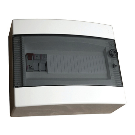
Compact control gear for Supply
EN
and Supply-Exhaust Air Handling Units
VS 10-75 CG OPTIMA
VS 40-150 CG OPTIMA SUP
VS 40-150 CG OPTIMA SUP-EXH
Operation and Maintenance Manual
DTR-CG OPTIMA – ver.2.0 (05.2012)
Summary of Contents for Ventus VS 10-75 CG OPTIMA
-
Page 1
Compact control gear for Supply and Supply-Exhaust Air Handling Units VS 10-75 CG OPTIMA VS 40-150 CG OPTIMA SUP VS 40-150 CG OPTIMA SUP-EXH Operation and Maintenance Manual DTR-CG OPTIMA – ver.2.0 (05.2012) -
Page 2
Control boxes VS 10-75 CG OPTIMA; VS 40-150 CG OPTIMA SUP; VS 40-150 CG OPTIMA SUP-EXH are designed according to the following European standards: EN 60335-1; EN 60439-1; EN 60439-3; EN 50082-1; EN 50081-1 www.vtsgroup.com… -
Page 3: Table Of Contents
Table of Content USER’S MANUAL ………………..3 1. DESCRIPTION OF CONTROLS ……………………….3 INTRODUCTION …………………………….3 MAINS SWITCH …………………………….3 SIGNALLING CONTROLLER STATUS ……………………….. 3 CONTROL PANEL HMI OPTIMA ………………………… 4 SYSTEM START-UP ……………………………. 5 SWITCHING ON POWER SUPPLY ……………………….5 QUICK START ……………………………..
-
Page 4
SETTINGS DX COOLER …………………………20 SETTINGS RECOVERY …………………………20 SETTINGS MIXING CHAMBER ……………………….21 ADVANCED MANUAL ………………22 6. SERVICE MENU …………………………..22 SERVICE MENU SERVICE MODE ……………………..22 SERVICE MENU CHOOSE APPLIC. ……………………..22 SERVICE MENU … -
Page 5: User’s Manual
○ extra functionality is backwater regulation for protection of the heater coil Range of operation: VS 40-150 CG OPTIMA SUP VS 10-75 CG OPTIMA VS 40-150 CG OPTIMA SUP-EXH Air handling units equipped with direct driven plug fans powered by frequency converters…
-
Page 6: Control Panel Hmi Optima
2. Green – COMM – to indicate the state of Modbus Master communication line a. Off – no communication, HMI OPTIMA not connected b. Blinking – in case of stable communication 1. All control boxes of the VS…CG OPTIMA… typeline need to be powered from the main switchgear equipped with appropriate protection of wires powering the control box.
-
Page 7: System Start-Up
Parameters available in the LCD window depends on a AHU type and the control application. Hence in AHUs not equipped with heater, options related to the heating module will not be visible. SYSTEM START-UP Operation of the AHU is strictly arrested by the fire-protection alarm, activation of the thermal protection of fans’ motors, threefold activation of the protection of electric heater and threefold activation of the anti-frost thermostat.
-
Page 8: Application Basics
2. APPLICATION BASICS MAIN MENU STRUCTURE Unit state Unit state – indicates the current state of the air handling unit and the control system Service mode ▪ Stop – normal stop of the unit Operation mode ▪ Running – normal operation of the unit with ventilation and Stop heating / cooling / recovery enabled according to current unit state and demand…
-
Page 9: Hmi Optima Settings & Connecting To The Controller
EN / PL / RU – jump to language selection Change password – allows entering specific password to protect the controller from unintended access v.2.1 20-04-12 – application identifier VS-OPTIMA – controller type identifier Note! All the menus are dynamically changed, as they depend on the application settings and the password level If the system did not start, check the F1 protection status …
-
Page 10: Language Selection English / Polski / Русский
HMI com speed / RS485M com speed – settings for communication speed between the HMI and the controller. First parameter refers to HMI speed, the other refers to the controller. Note! The speed settings must match each other. Otherwise the connection will be lost.
-
Page 11: Calendar Annual
CALENDAR ANNUAL Inside the “Annual” menu there are visible all previously stored New program programs and also the link to “New program” editor. Entering new program allows for setting: 01-01 00:00.00 ▪ Date and Time “from” 02-01 07:00.00 ▪…
-
Page 12: Calendar Example
CALENDAR EXAMPLE Intended scheme of operation for the office: 1. Daily: a. Normal working hours: 7 – 15 – work in “comfort” conditions b. Overtime: 15 – 17 – work in “comfort” conditions, but save energy c. Office empty overnight – keep only safe conditions, save much energy 2.
-
Page 13: Parameters
Time to 07:00.00 Operation mode Standby Temp. Setting 18°C Save Programming steps 3/4/5 – do the settings for daily operation New program CALENDAR DAILY NEW PROGRAM Time from: 07:00.00 Time from Time to: 15:00.00 07:00.00 Operation mode: Stage II Time to Temp.
-
Page 14: Parameters Dampers
PARAMETERS DAMPERS State of the intake / outlet dampers Dampers Closed ▪ Closed ▪ Opened PARAMETERS FANS Fan status State of the fans Stop Fans status – indicates which fans are currently running Supply fan rate ▪…
-
Page 15: Parameters Dx Cooler Status
PARAMETERS DX COOLER STATUS DX cooler status State of the DX cooler ▪ Off ▪ On Note! Cooler status could be affected not only by operation mode of the unit. Safe operation of the DX cooler requires some minimal working / resting times to be included in the control strategy.
-
Page 16: Parameters Recovery Rate
PARAMETERS RECOVERY RATE Readout of control signal for the rotary heat regenerator or plate Recovery rate cross-flow recuperator, range 0..100% PARAMETERS ROTARY REGEN. Rotary regen. State of the rotary heat regenerator Recovery rate Recovery rate — readout of control signal for the recovery unit, range 0..100% Frequency –…
-
Page 17: Settings Season
▪ Heating – standby enabled only for heating (unit starts when Standby hyster. the room gets too cold) 4°C ▪ Cooling – standby enabled only for cooling (unit starts when the room gets too warm) ▪ Heating/Cooling – standby enabled for both situations Note! Standby mode settings must be related to the heat exchangers actually available in the unit.
-
Page 18: Settings Temp. Regulator
SETTINGS TEMP. REGULATOR Supply T – setting for the upper limit of supply air Temp. Regulator temperature ▪ Low limit: 20°C Supply T ▪ High limit: 50°C 30°C ▪ Default: 40°C Supply T Supply T – setting for the lower limit of supply air temperature 15°C ▪…
-
Page 19: Settings Fans
– settings for frost protection PI regulator ▪ K – gain for the regulator ▪ T – integral factor for the regulator ▪ Default: K =5 / T =10s SETTINGS FANS Pressure delay – time to check the fan presostats after the fan Fans …
-
Page 20
Note! Between the points of Max and Min T.Out the valve Preheating time position is calculated with linear characteristics. For example at half the range, the valve will be 50% opened. Fall ramp Initial heating / Preheating time – setting for the initial heating timer. -
Page 21: Settings Preheater
Tbwtr setpoint — setting for the desired temperature of the backwater from the heater. If unit stopped, regulator keeps exactly the setpoint. If unit running, Tbwtr setpoint is considered as lower limit of backwater temperature. If the Tbwtr drops, the regulator forces the valve to open regardless to the main control loop for heating.
-
Page 22: Settings Clg Pump Prot
Pump protection / Stoppage period – setting of the resting time for the pump ▪ Low limit: 1day ▪ High limit: 30days ▪ Default: 7days Pump protection / Run time – setting of the operation time for the pump ▪ Low limit: 1s ▪…
-
Page 23: Settings Mixing Chamber
Frost prot. Frost prot. / T Frost prot. – settings for frost protection PI regulator ▪ K – gain for the regulator ▪ T – integral factor for the regulator ▪ Default: K =5 / T =10s SETTINGS MIXING CHAMBER Mix chamber …
-
Page 24: Advanced Manual
ADVANCED MANUAL 6. SERVICE MENU Service menu contains the most fundamental settings, necessary for proper configuration and safe startup of the unit. Moreover, some service–oriented functions are available here for easy maintenance and troubleshooting for service staff. SERVICE MENU SERVICE MODE Service mode –…
-
Page 25
▪ S6 (Aux) – external start/stop signal, NO voltage free contact Note! DI1 input mode setting are available only in N… applications where hardware input DI1 is a configurable resource. As the functions of hardware inputs are different for A… and N… applications, observe the control application diagrams and follow them strictly. -
Page 26: Service Menu Input States
RRG FC / … – the same settings for frequency converter of the rotary energy regenerator Response timeout – setting for max waiting for a slave to respond. If the time was exceeded, the error will be detected. It is recommended to not modify that parameter. Factory setting: 0,3s Comm break time –…
-
Page 27: Service Menu Output Forcing
SERVICE MENU OUTPUT FORCING Relay outputs – overwriting the actual states of hardware digital outputs ▪ REL1 – None / Force Off / Force On ▪ REL2 – None / Force Off / Force On ▪ REL3 – None / Force Off / Force On Analog outputs –…
-
Page 28: Alarm Handling
Note! Mind the proper addressing of the frequency converters, which is crucial for correct operation of the unit. Note! The LS frequency converters can be restored to factory configuration by setting the parameter H93 to 1 and consecutive switching Off and On again. Name of the parameter Code Value…
-
Page 29
Note! Each blocking alarm needs to be acknowledged separately. Holding the [OK] button affects only the alarm, that is currently displayed on the HMI. LIST OF SELF RELEASE ALARMS Alarm name Description Input Controller reaction A1_Filter dirty filter indication no reaction A2_FCsCom supply FC communication error Modbus… -
Page 30: Technical Data
9. TECHNICAL DATA VS10-75 CG VS 40-150 CG VS 40-150 CG Parameter OPTIMA OPTIMA SUP OPTIMA SUP-EXH Weight Dimensions W x H x D 240x300x130 240x400x130 240x400x130 Electrical supply system Rated power supply voltage ~230V 3~400V 3~400V Rated current In Rated insulation voltage Ui 400V Rated impulse withstand voltage Uimp…
-
Page 31: Cabling
Relay ouputs Max. switching voltage 250VAC Min. switching voltage 5VDC Rated current in AC1 / DC1 class Min. current 10mA Rated long term load 10. CABLING Connect power leads of the control box and frequency converter of the fan drive according to the Electric diagram.
-
Page 32
Name of element / connection point Symbol Wire type Section [mm cooling device start input 2×0,75 refrigerating unit start input – I stage E2.1 2×0,75 cooling device analog control signal (valve) 3×0,75 RRG frequency converter [1] [2] 3×1,5 / 4×1,5 RRG alarm switch RRG start input via Modbus… -
Page 33
Table B 0,55kW 0,75kW 1,1kW 1,5kW 2,2kW 5,5kW L1 L2 L3 L1 L2 L3 L1 L2 L3 L1 L2 L3 L1 L2 L3 L1 L2 L3 L1 L2 L3 L1 L2 L3 L1 L2 L3 L1 L2 L3 0,55 0,75 12,5 10 13 13 15,5 10 13 17,5 10… -
Page 34: Electric Diagrams
11. ELECTRIC DIAGRAMS VTS reserves the right to implement changes without prior notice Advanced manual…
-
Page 35
VTS reserves the right to implement changes without prior notice Advanced manual… -
Page 36
VTS reserves the right to implement changes without prior notice Advanced manual…
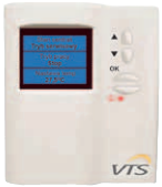
Пульт управления HMI OPTIMA
Описание

ПУЛЬТ УПРАВЛЕНИЯ HMI OPTIMA
HMI for Optima controller HMI OPTIMA
HMI Simple HMI OPTIMA
ФУНКЦИИ И ПРИМЕНЕНИЕ:
Задание и считывание параметров работы вентагрегата.
Выбор и конфигурация режима работы.
Установка режима работы по календарю.
Информация об аварийных состояниях.
ПАРАМЕТРЫ РАБОТЫ:
Напряжение электропитания: 230 В AC.
Частота тока: 50 Гц ± 1 Гц.
Напряжение питания цепей управления: 24 В AC.
Степень защиты: IP 20.
Температура окружающей среды: 0o
C..40o
C

Покупатели, которые приобрели Пульт управления HMI OPTIMA, также купили
![]()
Подключение водяных теплообменников VS и водяных охладителей WCL
Подключение водяных теплообменников VS должно быть выполнено таким образом, чтобы избежать напряжения, которое может привести к механическим повреждениям или образованию трещин. Ни тяжесть трубопровода, ни температурные перепады не должны быть направлены на патрубки водяного теплообменника. В зависимости от местных условий следует применять компенсацию в системе трубопроводов на входе и выходе в целях исключения продольного расширения трубопровода. При подключении трубопроводов теплоносителей к патрубкам теплообменников, имеющим резьбовые соединения, необходимо законтрить патрубок теплообменника дополнительным ключом. Подводящие коммуникации следует располагать таким образом, чтобы они не затрудняли доступ к другим секциям агрегата. Способ подключения коммуникаций к теплообменникам должен обеспечивать легкий демонтаж трубопровода в целях беспроблемного демонтажа теплообменника из агрегата в момент проведения обслуживания и ремонта.
Теплообменники VTS подключаются через патрубки к теплоносителям так, чтобы они работали в режиме противотока с потоком воздуха. Прямоточное подключение теплообменников может привести к снижению их тепловой мощности.
Электрический нагреватель
Кабели питания электронагревателя должны быть пропущены через панель корпуса с тыльной стороны. Если кабели протягиваются через инспекционную панель, то они не должны мешать открытию этих панелей при сервисных работах. Подключение нагревателя с управляющим модулем MDL.HE-AC производится непосредственно в секции нагревателя по Инструкции модуля управления MDL.HE-AC. В остальных случаях подключение питания электронагревателя следует выполнять через отдельный электрощит, не входящий в поставку автоматики VTS. Каждый нагревательный элемент электронагревателя отдельно подключается к клеммной колодке, находящейся сбоку нагревателя. Электронагреватель должен быть подключен так, чтобы он включался только после включения вентилятора. Кроме того, при остановке вентилятора электронагреватель должен быть отключен. В зависимости от установленной системы автоматики мощность нагревателя может регулироваться плавно или ступенчато. Для ступенчатой регулировки нагревателя, нагревательные элементы следует соединять в группы по три . Нагревательные элементы в каждой группе размещены симметрично в окне нагревателя. Мощностные возможности нагревателей в зависимости от метода подключения отдельных групп нагревательных элементов и количества подключенных групп указаны в таблице инструкции подключения.
На колодке имеются клеммы для подключения проводов заземления РЕ и нейтрального N (корпус нагревателя должен быть подключен к заземлению или нулевому проводу). Там же имеются клеммы 0,7 08 и 0,9 для термостата, который предохраняет от чрезмерного повышения температуры внутри нагревателя. Это может случиться при снижении расхода воздуха или его отсутствии. Спирали электрических элементов выходят из строя при перегреве и отсутствии охлаждения движущимся воздухом.
- Термостат обязательно должен быть подключен к системе управления нагревателя.
Работа термостата базируется на особенностях биметаллического элемента, размыкающего цепь управления питанием нагревателя при температуре окружающего термостат воздуха до 65?C. После аварийного выключения включение нагревателя происходит автоматически при снижении температуры на 20?C. После планового или аварийного (спровоцированного перегревом) отключения питания нагнетающий вентилятор должен работать еще определенное время (0,5-5 мин.), пока не остынут спирали электро нагревателя. В случае нагревателя с плавной регуляцией мощности все электрические подключения и конфигурацию системы управления нагревателя следует выполнять согласно указаниям, находящимся в Инструкции по эксплуатации нагревателя.
Двигатель вентилятора
Вентиляционные установки VS 10-650
Двигатели вентиляторов приспособлены для работы в пыльной и влажной среде (IP55), a их изоляция (класса F) приспособлена для работы с преобразователем частоты. Не требуется никаких дополнительных средств для защиты двигателей от условий в вентиляторной секции агрегата. Двигатели, используемые в агрегатах в стандартном варианте, имеют собственное охлаждение в виде вентилятора, установленного на валу электродвигателя. Кабели электропитания двигателя должны проходить через резиновые розетки в отверстиях в задней панели корпуса вентиляционной установки Ventus. В случае, когда отверстия для пропуска кабелей закрыты тонким слоем металла, следует его аккуратно убрать.
ВНИМАНИЕ! Кабели электропитания электро двигателя VTS нельзя проводить через инспекционные панели.
Двигатели вентилятора с прямым приводом малой мощности (до 2.2 кВт) запитываются напряжением 3х220В через однофазный (230 В) преобразователь частоты. Двигатели большей мощности запитываются напряжением 3х400В через трехфазный (3х400в) преобразователь частоты.
Перед подключением двигателя необходимо проверить номинальные значения напряжения питания и выхода с преобразователя частоты. Подключение двигателя должно выполняться с использованием защиты, подходящей для применяемого типа преобразователя. Если двигатель запитывается через преобразователь частоты, то подключать защиту нет необходимости. Она реализована в самом преобразователе и ее можно активировать посредством задания определенных параметров и прописыванием номинальных значений, в соответствие с инструкцией на преобразователь частоты. Если вентиляторная секция VTS укомплектована несколькими вентиляторами, то должна быть обеспечена их синхронная работа. Система управления вентиляторами должна обеспечивать синхронный запуск, остановку и контроль скорости вращения. В случае поломки или остановки одного из вентиляторов, вся секция должна быть остановлена. Внимание! На инспекционную панель вентиляторной секции установлен предохранительный выключатель, вызывающий остановку вентилятора в случае несанкционированного открытия инспекционной панели. Выключатель должен быть подключен к преобразователю частоты в соответствии со схемой, указанной в отдельном руководстве: «Управление и связь по протоколу Modbus. Приложение к руководству пользователя для LG iC5/iG5A».При подключении преобразователя частоты токи высокой частоты или гармонические составляющие напряжений в питающих двигатель кабелях могут возбуждать электромагнитные помехи. Соединение между преобразователем частоты и двигателем следует производить экранированными проводами согласно указаниям, представленными в Инструкции по эксплуатации преобразователя частоты.Перед первым запуском, а также после длительного простоя необходимо проверить сопротивление изоляции между корпусом и обмоткой постоянным током.Для новых, очищенных или восстановленных обмоток минимальное сопротивление должно быть10 M? относительно земли.


ПУЛЬТ УПРАВЛЕНИЯ HMI OPTIMA
ФУНКЦИИ И ПРИМЕНЕНИЕ:
- Задание и считывание параметров работы вентагрегата.
- Выбор и конфигурация режима работы.
- Установка режима работы по календарю.
- Информация об аварийных состояниях.
ПАРАМЕТРЫ РАБОТЫ:
- Напряжение электропитания: 230 В AC.
- Частота тока: 50 Гц ± 1 Гц.
- Напряжение питания цепей управления: 24 В AC.
- Степень защиты: IP 20.
- Температура окружающей среды: 0oC..40oC.
Рассказать друзьям!
Наши преимущества
-
Купить Flatty
Вступайте в ряды довольных пользователей универсального и инновационного шаблона для Webasyst!
-
Доставка
Мы доставим ваш заказ курьером по Москве и Петербургу или службой экспресс-доставки по всей России.
-
Оплата
Оплатите заказ банковской картой, наличными в ближайшем платежном терминале или наличными.
-
Розничный магазин
Будем рады видеть вас в нашем магазине по адресу г. Москва, ул. Крымский Вал, д. 3, стр. 2.
-
Как изменить
Откройте приложение магазин > витрина > дизайн > шаблоны > файл triggers.html
-
Несколько размещений
В настройках темы вы можете указывать на каких страницах выводить триггеры.
На главной и/или в категориях и/или в товарах!