-
Contents
-
Table of Contents
-
Bookmarks
Quick Links
Mitsubishi Heavy Industries Air Conditioners
Technical Manual
Manual Number: 2011 No. W1-01
Variable Frequency Wall Mounted Type
Room Air Conditioners
(Split system, heat pump type)
SRK25QA-S/SRC25QA-S
SRK35QA-S/SRC35QA-S
(R410A Refrigerant Used)
MITSUBISHI HEAVY INDUSTRIES, LTD.
-1-
Related Manuals for Mitsubishi Heavy Industries SRK25QA-S
Summary of Contents for Mitsubishi Heavy Industries SRK25QA-S
-
Page 1
Mitsubishi Heavy Industries Air Conditioners Technical Manual Manual Number: 2011 No. W1-01 Variable Frequency Wall Mounted Type Room Air Conditioners (Split system, heat pump type) SRK25QA-S/SRC25QA-S SRK35QA-S/SRC35QA-S (R410A Refrigerant Used) MITSUBISHI HEAVY INDUSTRIES, LTD. -
Page 2: Table Of Contents
Table of Contents 1. GENERAL INFORMATION……..…………………………….……1 1.1 Features…………………………………………………………..…1 1.2 Model identification………………………………………………1 2 MODEL SELECTION…………………………………………………2 2.1 Model function..…………..…….……..………………………..……2 2.2 Range of usage……………………………………………..………4 2.3 Outline drawing…..………………………………………………..…4 2.4 Cooling cycle system diagram….…………………..………………5 2.5 Performance curve……………………………………………………6 3 ELECTRICAL WIRING DIAGRAM………………………………….7 4 NAME OF EACH PART AND ITS FUNCTION……………….….….9 4.1 NAME OF EACH PART………………..………….………………9 4.2 Emergency “ON/OFF”…
-
Page 3
5.4 Pipe connection……………..28 5.5 Precautions for wireless remote controller operation……30 5.6 Standard running data…………….31 6 MAINTENANCE…………….32 6.1 Electrical parts failure diagnosis method……….32 6.2 Servicing…………………56 7 SERVICING MANUAL……………57 8 MOUNT ASSEMBLY…………………………………72 8.1 Indoor unit………………72 8.2 Outdoor unit………………80… -
Page 4: General Information
1 GENERAL INFORMATION 1.1 Features (1) Inverter ● Heating/cooling The rotate speed of the compressor is changed steplessly in relation to varying load, and is linked with the fans of indoor and outdoor units controlled by the changes of frequency, thus controls the power.
-
Page 5: Model Selection
2 MODEL SELECTION 2.1 Model function 2.1.1 Model: SRK25QA–S (Indoor unit) SRC25QA–S (Outdoor unit) Item Unit Indoor unit SRK25QA–S Outdoor unit SRC25QA–S Net weight 790×222×268 Machine 780×290×540 dimension Length× Width Package 830×340×280 920×380×590 ×Height dimension Color White Ash-colored Through-flow type, AS resin + glass Axial flow type, AS resin + glass fiber fiber…
-
Page 6
2.1.2 Model: SRK35QA–S (Indoor unit) SRC35QA–S (Outdoor unit) Item Unit Indoor unit SRK35QA–S Outdoor unit SRC35QA–S Net weight 790×222×268 Machine 780×290×540 dimension Length× Width Package 830×340×280 920×380×590 ×Height dimension Color White Ash-colored Through-flow type, AS resin + glass Axial flow type, AS resin + glass fiber fiber (embedded damping spindle sleeve) -
Page 7: Range Of Usage
(Purging is not required even for the short piping.) 2.2 Range of usage Please use the air conditioners within the following range of usage, otherwise the protector will be triggered. Cooling Operation Heating Operation Outdoor temperature About 18℃~43℃ About -15~24℃ Room temperature About18℃~32℃…
-
Page 8: Cooling Cycle System Diagram
(2) Outdoor unit: SRC25QA-S/ SRC35QA-S Unit: mm Drain holes Terminal block Flare connecting Flare connecting Operation valve (Gas) Operation valve 2.4 Cooling cycle system diagram (Liquid) Models: QA-S Series Circulation of cooling Indoor unit Outdoor unit Circulation of heating Operation valve (Gas) Flare connecting Outdoor air temp.
-
Page 9: Performance Curve
1.00 ⑷ Example of cooling and heating capacity calculation: The actual cooling capacity of model SRK25QA-S with the one way piping length of 25m at the indoor wet-bulb temperature of 19℃ and outdoor dry-bulb temperature of 35℃in summer or indoor dry-bulb temperature of 20℃, outdoor dry-bulb temperature of 1℃and indoor wet-bulb temperature of -1℃…
-
Page 10: Electrical Wiring Diagram
3 ELECTRICAL WIRING DIAGRAM 3.1 Circuit diagram: 25QA-S…
-
Page 11
3.2 Circuit diagram: 35QA-S… -
Page 12: Name Of Each Part And Its Function
4 NAME OF EACH PART AND ITS FUNCTION 4.1 Name of each part Indoor unit Air inlet panel Draws in the indoor air. Unit indication section and remote control signal receiver Wireless remote control Air filter Removes dust or dirt from the inlet air filtere Room temperature detector filtere…
-
Page 13
Indication section of air conditioner RUN lamp (green) ON during running and mould-proof running HI POWER lamp (green) ON during Hi Power running ECONO lamp (green) TIMER lamp (yellow) ON during running ON during timing operation ECONO Opening the air inlet grille Put your hands on the indentations on both sides, raise the grille towards yourself, and stop at the opening position of about 60°. -
Page 14: Operation And Indication Section For Remote Control
Operation and indication section for remote control Operation section FAN SPEED button OPERATION MODE select button Each time the button is pushed ■ Each time the button is pushed ■indicator is indicator is switched over in turn. switched over in turn. HI POWER/ECONOMY button ON/OFF button This button changes the HI PO-…
-
Page 15: Emergency «On/Off» Button (Back-Up Switch)
4.2 Emergency “ON/OFF” button (back-up switch) When the battery of the remote controller runs out or the remote controller is lost or malfunctioning, this switch can be used to turn the unit on and off. (1) Operation method Press the switch once to place the unit in the AUTO mode. Push it once more to turn the unit off. (2) Detail of operation The system operates in the COOL, DRY or HEAT mode according to the room temperature (temperature at the temperature detection point).
-
Page 16
(3) Flap memorizing function (where the vertical or horizontal flap stops) When you press the AIR FLOW (Up/Down or Left/Right) button, the flap will operate at the angle set. As this angle is memorized in the microcomputer, the flap will automatically operate at the same angle next time the machine is started. -
Page 17: Comfort Timer Setting
4.5 Comfort timer setting If, in the COOL or HEAT mode or Automatic COOL or HEAT mode, the timer is set to ON, the Comfort Timer functions. The initial value is 15 minutes. The start time for next operation is determined according to the relationship between the room temperature (sensor) at the time of setting and the set temperature (max.
-
Page 18: Outline Of Heating Operation
If the frequency obtained with the fuzzy calculation drops below -24 rps during the heating fuzzy operation, the operation changes to the heating constant temperature operation. ● Detail of operation Model SRK25QA-S, SRK35QA-S Item Inverter instruction 0 rps [Comp. stopped] frequency Heat-retaining (normal operating mode)→1st speed (OFF)
-
Page 19
● Heat-retaining M mode (automatic, economical operation (15 minutes)) ● Values of A, B Indoor fan At 0 rps instruction Other than 0 instruction Temp. of indoor heat exchanger (°C) Note: (1) For the values of A and B, see the above table. (d) Defrosting operation 1) Starting conditions (The defrosting operation is started only when all of the following conditions are met.) -
Page 20: Outline Of Cooling Operation
If the frequency obtained with the fuzzy calculation drops below -24 rps during the cooling fuzzy operation, the operation changes to the cooling constant temperature operation. ● Detail of operation Model SRK25QA-S, SRK35QA-S Item Inverter instruction 0 rps [Comp. stopped] frequency…
-
Page 21: Outline Of Drying Operation
(c) HI POWER Cooling operation (HI POWER button on remote controller: ON) Unrelated to set temperature. Continuous operation for15 minutes. ● Detail of operation Model SRK25QA-S SRK35QA-S Item Inverter instruction frequency Indoor fan 7th speed Outdoor fan Corresponding to instruction frequency Notes: (1) Room temperature can’t be adjusted during the HI POWER operation.
-
Page 22
(B) Prevent Range I in jiggle operation from changing to Range C operation. -19-… -
Page 23
● Operation of Range I: 1st speed Indoor fan 25 sec. 5 min. Temperature and humidity check Temperature and humidity check (b) Heating & drying After heating & drying is determined, heating operation begins 3 minutes (3 min. timer) after the stop of the compressor. When the room temperature TION is higher than the set temperature SP by more than 2℃, the room temperature TION and set temperature SP are checked every 5 minutes to determine the operation range of heating &… -
Page 24: Outline Of Automatic Operation
In this case, the temperature in the Cooling mode is higher than the set temperature by 1.5ºC (increasing 0.5ºC per hour), and the temperature in the Heating mode is lower than the set temperature by 2.5ºC (decreasing 0.5ºC per hour). Model SRK25QA-S SRK35QA-S Item Operating mode…
-
Page 25: Clean Operation Control
4.12 CLEAN operation control About CLEAN operation: In the cooling and drying mode, when the unit is turned off, the fan of the indoor unit will continue to run for 120 minutes to discharge the water from the unit for the purpose of mould-proof.
-
Page 26: Installation
5 Installation Precautions for installation ○ Use this system only for household and residence. ○ This appliance must be installed according to the national wiring regulation. ○ A 2-level switch must be used for the fixed wiring of the power supply and its disconnection clearance must be at least 3mm.
-
Page 27
WARNING • To recover refrigerant, stop the compressor before closing the valve and disconnecting the refrigerant piping. If the refrigerant piping is disconnected before the compressor stops and when the service valve is opened, it can cause frostbite or injury due to rapid refrigerant leakage, and burst or personal injury due to anomalously high pressure in the refrigerant circuit into which air is sucked •… -
Page 28: Selection Of Installation Location
CAUTION • Do not install the outdoor unit in the locations listed • Do not install the outdoor unit in a location where below. insects and small animals can inhabit. • Locations where discharged hot air or operating sound of Insects and small animals can enter the electric parts and the outdoor unit can bother neighborhood.
-
Page 29
Selection of installation location Indoor unit At least 6.5 cm from ceiling ○ Where there are no obstructions and where At least 5 cm from wall Mounting plate cool air and warm air can blow in the room. At least 10 cm from wall ○… -
Page 30: Installation Of Indoor Unit
Installation of indoor unit Drilling holes and securing sleeve (optional) Adjusting the length of the sleeve Drilling a hole with Φ65 whole core drill Indoor Outdoor Thickness of wall ○ If the rear pipe is pulled out, cut the Use the whole core drill to drill a hole. lower part and right side of the axle collar Mounting the sleeve.
-
Page 31
The pipe can be connected to the rear, left, left rear, bottom left, Mounting pipe support right or bottom right. Removing Connecting the pipe to the left Connecting the pipe to the right [Steps for drainage pipe drainage pipe displacement] Connecting the pipe to the Connecting the pipe to the left Pipe… -
Page 32: Installation Of Outdoor Unit
Drainage pipe After all mounting steps, check Caution ○ Mount the drainage pipe at a downward angle. whether drain proper. ○ Avoid the following drainage pipe connections. Otherwise, water leakage may occur. Odor from sink End of drainage pipe Higher than as required Undulating Less than 5cm away End of drainage…
-
Page 33: Air Purging
Measurement B Flaring Model Copper pipe Clutch type flare tool Conventional (R22) flare tool diameter for R410A Clutch type Wing nut type Measurement B Use a flare tool designed for R410A or a conventional flare tool. Please note that measurement B (protrusion from the flaring block) will vary depending on the type of flare tool in use.
-
Page 34: Precautions For Wireless Remote Controller Operation
Moving or removing the appliance ○ In order to meet the requirement of environmental protection, pump down (recovering refrigerant) is required. ○ The effect of pump down is to return the refrigerant from the indoor unit to the outdoor unit when the pipes are removed from the main frame.
-
Page 35: Standard Running Data
5.6 Standard running data: SRK25QA-S SRK35QA-S High pressure (MPa) Cooling Heating 2.2-2.9 2.0-3.2 Low pressure (MPa) Cooling 1.0-1.2 0.9-1.2 Heating Temp. difference between inlet Cooling 9-11 8-14 Heating 9-16 10-21 and outlet air of indoor unit (℃) Operating current (A) Cooling 1.4-3.5…
-
Page 36: Maintenance
6. MAINTENANCE 6.1 Electrical parts failure diagnosis method (1) Precautions: ① Be sure to switch off the power before disassembling and checking the air conditioner. Maintenance of the indoor unit should commence 1 minute after the power is switched off. With respect to maintenance of the outdoor unit, the major circuit (electrolytic capacitor), which may be charged, should be fully discharged before the maintenance.
-
Page 37
Procedure of diagnosis (when the air * Correct voltage refers to the voltage between 198-242V. conditioner does not run at all) Has the cable been Check that the cable is inserted inserted in the power in the correct power supply. supply with correct Check the operation situation. -
Page 38
(4) Procedure of failure diagnosis (when the air conditioner can run) Confirm the content of failure of the user’s air conditioner. Is the cause of error confirmed? Confirm the displaying of self-diagnosis. Eliminate the cause of error and check the operation situation. -
Page 39
(5) Indication of self-diagnosis When the air conditioner stops abnormally, the cause is indicated with lamps. Three minutes after abnormal stop, use the remote controller to start the appliance. The error indication will disappear and the appliance will commence operation Indoor indication Content of failure Main cause… -
Page 40
(6) Service mode (failure mode reading function) The air conditioner records the past error indication and protection stops (service data). If the indication of self-diagnosis can’t be confirmed, it can be confirmed through service data to grasp the condition when the error occurs. (a) Terms Term Description… -
Page 41
*3: Counting of flashing in service mode: 1.5 sec. light-up (beginning signal) and number of continuous flashes (Number of continuous flashes excluding the 1.5 sec. light-up (beginning signal)). ● Safe current (heating safety I) (for example, the stop code is “32”) RUN lamp (tens place) flashes 3 times and TIMER lamp (ones place) flashes 2 times: 3 x 10 + 2 x 1 = 32. -
Page 42
② Stop data Settings of remote controller Operation Air flow Temperature switching switching setting Indication data Cooling 21℃ Indicates the cause of the last stop due to protection control, etc. (stop code) 22℃ Indicates the cause of second to last stop due to protection control, etc. (stop code) 23℃… -
Page 43
(c) List of error codes and stop codes (for all models) No. of flashes in Content of Error Automatic Cause Conditions service mode Stop failure indication restoration code or error code TIMER lamp lamp Category Class (tens (ones place) place) Normal Flash 1 Flash 1… -
Page 44
Flash 6 Heating safe Excessive refrigerant Safe current stops in the safe current III times current III mode during heating operation. Compressor lock Flash 7 Heating safe Excessive refrigerant Safe current stops in the safe current times current III III+3A mode during heating operation. Compressor lock -41-… -
Page 45
No. of flashes in Stop Content of Cause Conditions Error Automatic service mode code or failure indication restoration error code TIMER Category Class lamp lamp (ones (tens place) place) Flash 1 Safe current Cooling Excessive refrigerant Stops in the overload 1 mode during Flash 4 time overload 1… -
Page 46
Flash 8 Cooling cycle Disconnecting valve closed The cooling cycle system protection times system Insufficient refrigerant control operates. protection control -43-… -
Page 47
Notes: (1) The number of flashes in service mode excludes the 1.5 sec. light-up (beginning signal). (See the following example.) ● Safe current (heating safety I) (for example, the stop code is “32”) RUN lamp (tens place) flashes 3 times and TIMER lamp (ones place) flashes 2 times: 3 x 10 + 2 x 1 = 32. -
Page 48
(e) List of temperatures measured by room temperature sensor, indoor heat exchanger sensor, outdoor air temp. sensor, and outdoor heat exchanger liquid pipe sensor Unit: ℃ TIMER lamp (ones place) RUN lamp (tens place) Does the buzzer sound? (Sound means negative) (Sounds for 0.1 sec.) (Not sound) -
Page 49
0.1 sec. When the temperature is < 0, the buzzer will sound. Sound of When the temperature is ≥ 0, the buzzer will not sound. buzzer (Negative) 1.5 sec. RUN lamp (tens place) 0.5 sec. 0.5 sec. TIMER lamp (ones place) 11 sec. -
Page 50
(f) List of temperatures of compressor vent-pipe Unit: ℃ TIMER lamp (ones place) RUN lamp (tens place) Does the buzzer sound? (Sound means negative) (Sounds for 0.1 sec.) (Not sound) * If there is no data recorded (the error code is normal), the information of each sensor is as showed in the table below: Value displayed by the sensor when the error code is Name of sensor… -
Page 51
Check data recording sheet Customer Model Date Equipment name Complaint Content of Settings of remote controller Content of indication data Indication result indication RUN lamp TIMER lamp Temp. Operation Air flow Buzzer (no. of (no. of setting switching switching (yes/no) times) times) Code of last error… -
Page 52
(7) Check method according to the content of failure Error of sensor (Wire break of sensor and poor joint contacting) Is the joint contacting normal? Correct the plug/socket (replace the joint) Is the resistance value of the sensor Replace the sensor. normal? Replace the PCB. -
Page 53
Error of outdoor unit (Damage of power transistor, wiring break of compressor) Failure of inverter Check the compressor. Conne ct it proper Compressor over heat (Insufficient refrigerant, failure of discharge pipe sensor) Is the resistance value of the Check that the connection of the connector is discharge pipe sensor normal? correct;… -
Page 54
Serial signal transmission error (Wrong power supply and signal cable connection, failure of indoor and outdoor PCB, error of power supply system) Failure caused by one-time reason Correct the indoor and outdoor connection (noise, etc.), not failure of machine Failure of indoor PCB Check the connection Is there AC voltage of Failure of indoor PCB. -
Page 55
Outdoor fan motor error (Failure of fan motor, failure of outdoor PCB) Is the connection of the connector Correct the connector. normal? Has voltage been applied to the fan Failure of outdoor PCB motor? Failure of fan motor (8) Actions in case of short circuit and wire break of sensor (a) Indoor unit Sensor Operation… -
Page 56
(9) Check method for indoor electrical components Is the fuse (3.15A) intact? Replace the fuse. Has voltage been applied to Replace the PCB. between terminal block 1~2 (AC220/230/240V)? Dose the voltage between terminal Replace the PCB. block 2~3 fluctuate between DC 0~12V? Notes: (1) Communication is sent only when 52C is ON, so please check the operation status. -
Page 57
(11) Remote controller failure diagnosis procedure Note (1) Is the remote ●Low battery of remote controller controller ● Defective remote controller Replace normal after reset? Restart Note (1) Does the air No error (a) Press the ACL switch on the remote controller. conditioner (b) If the set temperature displayed is 0℃… -
Page 58
(12) Check method for outdoor unit 1) Circuit diagram of 25QA-S outdoor unit -55-… -
Page 59
2) Circuit diagram of 35QA-S outdoor unit -56-… -
Page 60
(13) Check method for outdoor circuit board (inverter) Make confirmation after checking that the indoor circuit board is normal. (I) Use a multimeter to conduct inspection. a) Unplug the plug. b) Remove the output cables U, V and W (to the compressor) of the power transistor. (Note: The inspection of inverter can be conducted only after the capacitor is discharged and after making sure the residual voltage is below 10V.) c) Insert the plug and press and hold the back-up switch for over 5 sec. -
Page 61
(14) Check method for EEV After the power is switched on, check the opening of the EEV and the sound and voltage within 10 sec. of operation. [In operation, only the opening is changed and the voltage can’t be measured.] 1) If sound of the EEV is heard, it indicates the EEV is basically good. -
Page 62
2) 35QA-S uses DC motor. ● Failure diagnosis method for outdoor circuit board or motor when the fan motor can’t operate ● Check it after confirming the indoor unit is normal. (1) Output check of outdoor circuit board 1) Unplug the plug. 2) Remove the plug CAN for the outdoor fan motor. -
Page 63: Servicing
6.2 Servicing (1) Evacuation Evacuation refers to the process of purging non-condensable gas, air, water, etc. from the refrigerant equipment with a vacuum pump. The R410A refrigerant is highly water insoluble, therefore even a little water left in the refrigerant equipment will be frozen, which causes the so-called water blockage. The refrigeration oil of the compressor is esterification oil or synoil which has strong hygroscopicity, so deposit may be formed easily when foreign matters enter, which causes many inexplicable faults.
-
Page 64
7 Service Manual for Air Conditioners with Refrigerant Piping Mounted/Using R410A Refrigerant (The following is selected from the document published by The Japanese Refrigeration and Air Conditioning Industry Association) 7.1 Overview 7.1.1 R410A Refrigerant (1) Using R410A in air conditioners In 1974, scientists found that the ozone in the upper stratosphere (about 20-40 km away from the ground) may be damaged by ozone depleting substances such as CFC (chlorofluorocarbon) and HCFC (hydrochlorofluorocarbon), etc. -
Page 65
(3) Lubricants for R410A Mineral oil, AB (Alkybenzene), etc. are widely used as the lubricants for R22. R410A is not easily dissolved in conventional lubricants such as mineral oil, etc. and such lubricants likely stay in refrigerant cycle, so ester, ether and other synoil in which R410A is highly dissoluble are generally used. -
Page 66
(2) Joints Copper pipes use flared joints or sleeve joints. Be sure to clean them before use. a) Flared joints Flared joints are used to connect copper pipes that can’t be used for piping as their outside diameter exceeds 20mm. In such case, sleeve joints may also be used. The sizes of ends of flared pipes, ends of flared joints and flare nuts are shown in Tables 5~8 (see pages 112 and 113). -
Page 67
d) Flaring Ensure to clean the clamps and copper pipes. Use the clamping bars to conduct flaring correctly. Use the flare tools for R410A or conventional flare tools. The size of flaring varies depending on the kinds of flare tool. the size must be adjusted to “Size A”… -
Page 68
Table 8 Sizes of R22 flaring and flare nut [Unit: mm] Rating Outside Thickness Size Width of flare nut diameter diameter (2) Flaring procedure and precautions a) Ensure there is not any defect or dust, etc. on the flaring and connection. b) Correctly connect the flared surface and the joint axis. -
Page 69
(2) Characteristics a) Pipe sleeve Copper pipes as R410A pipe sleeves must have a thickness as shown in Table 3 (see Page 59) and Tables 5 and 6 (see Page 61), and sizes of flaring and flare nuts different from those of R22. -
Page 70
(3) Welding flux a) Reasons for using welding flux ● To remove the oxide film and impurity from metal surface to help the flow of brazing filler. ● To prevent oxidization on metal surface in welding. ● To reduce the surface tension of brazing filler to make it better adhere to the treated metal. b) Features of welding flux required ●… -
Page 71
Reducing valve Flowmeter Disconnecting valve From nitrogen cylinder Piping Nitrogen Rubber stopper for sealing Figure 5 Preventing oxidation in welding * Precautions for welding ① General precautions 1) The weld strength should meet the requirement. 2) Keep air tightness under the pressure condition after the operation. 3) During welding, avoid damaging the components due to high temperature. -
Page 72
(1) Tools for R410A a) Manifold pressure gauge ● As R410A has the property of high pressure, conventional tools can’t be used. Table 11 Difference between conventional high/low pressure gauge and pressure gauge for R410A Conventional pressure gauge Pressure gauge designed specifically for R410A High pressure gauge (Red) Compound pressure… -
Page 73
e) Flare tool (clutch type) ● The flare tool for R410A has a big clamping bar receiving hole, so as to set the copper pipe portion protruding from the clamping bar during flaring to 0~0.5mm and have stronger elasticity for the increased torque of EEV. This type of flare tool can also be used for R22 copper pipes. -
Page 74
7.3.2 New installation (when new refrigerant piping is used) (1) Use the vacuum pump to suction air and detect any gas leakage (see Figure 6) a) Connect the charge hose to the outdoor unit. ① b) Connect the charge hose to the vacuum pump adapter. ② Here, fully close the control valves. -
Page 75
f) After charging the liquid refrigerant into the air conditioner by closing the charging valve, fully close Valve Lo of the manifold pressure gauge to stop. ②⑤ g) Quickly move the charge hose away from the service opening.⑥ If the movement is slow, the circulating refrigerant may be leaked. h) Secure the covers of the service opening and control valve, and check for any gas leakage around the covers. -
Page 76
7.3.6 Recharging refrigerant in servicing If it is necessary to charge refrigerant, charge the specified amount of refrigerant by following these steps. (For details, see the operation manual prepared by the equipment manufacturer.) 1) Connect the charge hose to the service opening of the outdoor unit. 2) Connect the charge hose to the vacuum pump adapter. -
Page 77
(4) Recovery procedure a) According to the instructions on refrigerant recovery device (see the operation manual supplied), operate the device to recover refrigerant. b) Pay attention to the following during the operation. ① Confirm that the refrigerant recovery device runs according to the requirements and the operation status is always monitored, so as to take correct actions in case of emergency. -
Page 78
b) Charge hose (pressure resistant fluorocarbon hose) and sealing ring ● Thickness 1/48, multiple lengths available ● Hose with the pressure resistance property higher than 5.2MPa (52kg/cm ● In general, only one end has fixture. Hose sealing ring Fixture (4) Manifold pressure gauge ●… -
Page 79: Mount Assembly
8 MOUNT ASSEMBLY 8 DISASSEMBLY EXPLANATORY DRAWING 8.1 Indoor unit 8.1.1 SRK25QA-S RAC-SRK25QA-S-HEAT& EXCH&CONTROL Part No Parts RE.Q RYD301A055A HEAT EXCH ASSY(AIR) 2 RYD315D013 HEADER ASSY 3 RYD321A061 PIPE 4 RYD129A053 BRACKET ASSY(L) RYD321A049C PIPE ASSY 6 RYG323F002 UNION,SOLDER 7 RYG323F002A…
-
Page 80
17 RYD503A011A DISPLAY ASSY 18 RYD505A029A PWB ASSY(DISPLAY) 19 RYF941F001 SPRING,LEAF 20 RYD142A041 COVER 21 RYD502A016 CONTROL ASSY,REMOTE 22 RYD008A043D PARTS,STANDARD 23 RYD012A192 MANUAL,INSTRUCTION&INST 24 RYD011H050D ENERGY LABEL -77-… -
Page 81
-78-… -
Page 82
RAC-SRK25QA-S-PANEL&FAN ASSY Part No Parts RE.Q RYD102A024AH PANEL ASSY,FRONT 1 RYD435A050C GRILLE,AIR INLET(A) 2 RYD437A015 3 RYD129A046A 4 W010D04X008 TAP-SCREW,CRS-TRS 2 5 RYD122A017R PANEL,FRONT 6 RYG923C001 BEARING,PLANE 7 RYD431G001 IMPELLER 8 RYD511A015 MOTOR,AC 9 RYD129A039 COVER(MOTOR) 10 RYD132A005 11 RYD111A010… -
Page 83
18 RYD436A018J FLAP(A) 19 RYD436A019J FLAP(B) 20-21 RYD436A021 LOUVER ASSY 20 RYD436A020 LOUVER 21 RYD129A048 PLATE,CONNECTING -80-… -
Page 84
8.1.2 SRK35QA-S RAC-SRK35QA-S-HEAT& EXCH&CONTROL Part No Parts RE.Q RYD301A036F HEAT EXCH ASSY(AIR) 2 RYD315D015 HEADER ASSY 3 RYD321A065 PIPE 4 RYD129A053 BRACKET ASSY(L) RYD321A049C PIPE ASSY 6 RYG323F002 UNION,SOLDER 7 RYG323F002A UNION,SOLDER 8 RYD129A038 PLATE,BAFFLE 9 RYD142A037 BOX,CONTROL 10-16 RYD501A068K CONTROL ASSY 10-12 RYD505A055C… -
Page 85
14 RYD566A094 CORD,POWER 15 RYG561B001A BLOCK,TERMINAL 16 RYD011G018A LABEL,WIRING 17 RYD503A011A DISPLAY ASSY 18 RYD505A029A PWB ASSY(DISPLAY) 19 RYF941F001 SPRING,LEAF 20 RYD142A041 COVER 21 RYD502A016 CONTROL ASSY,REMOTE 22 RYD008A043D PARTS,STANDARD 23 RYD012A192 MANUAL,INSTRUCTION&INST 24 RYD011H050F ENERGY LABEL -82-… -
Page 86
RAC-SRK35QA-S-PANEL&FAN ASSY -83-… -
Page 87
Part No Parts RE.Q RYD102A024AH PANEL ASSY,FRONT 1 RYD435A050C GRILLE,AIR INLET(A) 2 RYD437A015 3 RYD129A046A 4 W010D04X008 TAP-SCREW,CRS-TRS 2 5 RYD122A017R PANEL,FRONT 6 RYG923C001 BEARING,PLANE 7 RYD431G001 IMPELLER 8 RYD511A015 MOTOR,AC 9 RYD129A039 COVER(MOTOR) 10 RYD132A005 11 RYD111A010 BASE ASSY 12 RYD032A006A PLATE,INSTALLATION 13-21… -
Page 88
20-21 RYD436A021 LOUVER ASSY 20 RYD436A020 LOUVER 21 RYD129A048 PLATE,CONNECTING -85-… -
Page 89: Outdoor Unit
8.2 Outdoor unit 8.2.1 SRC25QA-S SRC25QA-S-HEAT EXCH&CONTROL Parts No Parts Name RE.Q RYF301A042 HEAT EXCH ASSY(AIR) 2-10 RYF304A156F PINING ASSY(4WAY) RYF325A005 PIPE,SHELL RYC325A001 PIPE,SHELL RYF382C010 VALVE,S(4WAY) RYF304A109B PIPING ASSY(EXPAN) SSA387F062 VALVE,BODY(EXP) RYF315B048 CAPILLARY RYG357A003 STRAINER RYF116A008 BRACKET,VALVE RYF381A070 VALVE,SERVICE(1/4″) RYF381A069 VALVE,SERVICE(3/8″) RYF154D009B INSULATION,COMP…
-
Page 90
17-23 RYF200A057 FINAL ASSY,COMP RYF932C019 RUBBER WASHER AHT201A864DS COMPRESSOR ASSY SSA914C013A NUT,FLANGE RYF941C014 CUSHION,RUBBER RYF932C018 GASKET,COVER RSA947K005 COVER,TERMINAL RYF914C008 NUT,FLANGE SSA941C294 CUSHION,RUBBER 25-42 RYF501A040D CONTROL ASSY RYF505A008B PWB ASSY RYF011G020C LABEL,WIRING RYG561B001A BLOCK,TERMINAL RYG564A002 HOLDER,FUSE RYG564A003 FUSE(CURRENT) RYG551A009 SENSOR ASSY RYF504A021C WIRING ASSY RYF554B001… -
Page 91
RYF142A017 BOX ASSY,CONTROL RYF142A010 BOX,CONTROL(A) RYF116A015 BRACKET RYF116A014 BRACKET(TB) RYF142A011 RYF505A010 PWB ASSY(SUB) (43) RYF011F037D LABEL,MODEL NAME (44) RYF011H029D ENERGY LABEL (45) RYC008A002 PARTS,STANDARD (46) RYA008A015G PARTS SET Примечание [微软用户1]: 删除此行 -88-… -
Page 92
-89-… -
Page 93
SRC25QA-S-PANEL&FAN ASSY Parts No Parts Name RE.Q RYF122A002 PANEL ASSY,FRONT RYF124A001A PANEL,TOP RYF123A002 PANEL,SIDE(R) RYF435A003A GRILL ASSY,AIR OUT RYF132A002 PANEL ASSY,SERVICE RYF944B001 HANDLE RYF142A013 COVER(TB) RYF913A002 SCREW,TAP RYF913A002A SCREW,TAP W010D04X008 TAP-SCREW,CRS-TRS 1 W010D04X012 TAP-SCREW,CRS-TRS 1 12-15 RYF401A011K FAN EQUIP ASSY RYF116A006 BRACKET ASSY,MOTOR RYF511A049… -
Page 94
-91-… -
Page 95
8.2.2 SRC35QA-S SRC35QA-S-HEAT EXCH&CONTROL Parts No Parts Name RE.Q RYF301A044A HEAT EXCH ASSY(AIR) 2-10 RYF304A169A PINING ASSY(4WAY) RYF325A005 PIPE,SHELL RYC325A001 PIPE,SHELL RYF382C010 VALVE,S(4WAY) RYF304A170 PIPING ASSY(EXPAN) SSA387F051 VALVE,BODY(EXP) RYF315B048 CAPILLARY RYG357A003 STRAINER RYF116A008 BRACKET,VALVE RYF381A070 VALVE,SERVICE(1/4″) RYF381A069 VALVE,SERVICE(3/8″) RYF154D009B INSULATION,COMP RYF154D013 INSULATION,COMP RYF154D037… -
Page 96
RYF932C019 RUBBER WASHER AHT201A864DS COMPRESSOR ASSY SSA914C013A NUT,FLANGE RYF941C014 CUSHION,RUBBER RYF932C018 GASKET,COVER RSA947K005 COVER,TERMINAL RYF914C008 NUT,FLANGE SSA941C294 CUSHION,RUBBER 25-41 RYF501A040F CONTROL ASSY RYF505A008C PWB ASSY RYF011G020D LABEL,WIRING RYG561B001A BLOCK,TERMINAL RYG564A002 HOLDER,FUSE RYG564A003 FUSE(CURRENT) RYG551A009 SENSOR ASSY RYF504A021C WIRING ASSY RYF554B001 REACTOR RYF941F001 SPRING,LEAF… -
Page 97
RYF142A010 BOX,CONTROL(A) RYF116A015 BRACKET RYF116A014 BRACKET(TB) RYF142A011 (42) RYF011F037F LABEL,MODEL NAME (43) RYF011H029F ENERGY LABEL (44) RYC008A002 PARTS,STANDARD (45) RYA008A015G PARTS SET Примечание [微软用户2]: 删除此行 -94-… -
Page 99
SRC35QA-S-PANEL&FAN ASSY Parts No Parts Name RE.Q RYF122A002 PANEL ASSY,FRONT RYF124A001A PANEL,TOP RYF123A002 PANEL,SIDE(R) RYF435A003A GRILL ASSY,AIR OUT RYF132A002 PANEL ASSY,SERVICE RYF944B001 HANDLE RYF142A013 COVER(TB) RYF913A002 SCREW,TAP RYF913A002A SCREW,TAP W010D04X008 TAP-SCREW,CRS-TRS 1 W010D04X012 TAP-SCREW,CRS-TRS 1 12-15 RYF401A011F FAN EQUIP ASSY RYF116A006 BRACKET ASSY,MOTOR SSA512T094A… -
Page 100
RYF937A002A CLAMP,WIRE… -
Page 101
VARIABLE FREQUENCY WALL MOUNTED TYPE ROOM AIR CONDITIONERS MITSUBISHI HEAVY INDUSTRIES EUROPE, LTD. -
Page 102
AIR-CONDITIONING DIVISION 4th Floor, International Buildings, 71 Kingsway London WC2B 6ST, U.K. Phone: +44 (0) 20 7421 6208 Fax: +44 (0) 20 7421 6209…

Скачать каталог кондиционеров Mitsubishi Heavy Industries 2017
Инструкции кондиционеров Mitsubishi Heavy Industries Ltd делятся на три группы.
Инструкция пользователя, User Manual.
Как правило, это инструкция к пульту Mitsubishi Heavy Industries Ltd. У бытовой линейки это ИК-пульт, у полупромышленных и мультизональных блоков в инструкции кондиционера Митсубиси дополнительно описаны проводные пульты.
Справочные данные. Data Book.
Для соответствующей серии приводятся полные технические характеристики Mitsubishi Heavy Industries, включая электрические, гидравлические, массо-габаритные параметры, таблицы производительности. Поскольку в адаптированных коммерческих каталогах иногда встречаются ошибки (опечатки), при проектировании лучше пользоваться оригинальными справочными данными.
Сервисное руководство, Service Manual.
Предназначенные для сервисных специалистов сервис мануалы кондиционеров Mitsubishi Heavy Industries содержат информацию по всем ошибкам оборудования, их возможным причинам и способам устранения проблем. Дополнительно включены рекомендации по установке кондиционеров Митсубиси Хэви, сервисному обслуживанию кондиционеров Mitsubishi Heavy Industries, инструкция пульта управления кондиционера Митсубиси Хэви.
Обновлено: 06.09.2023

Mitsubishi Heavy Industries — одна из ведущих компаний на рынке систем кондиционирования. Покупатели охотно доверяют этому бренду, поскольку уверены в качестве и надежности продукции. Но, чтобы полностью раскрыть достоинства кондиционеров Митсубиси, важно изучить инструкцию по эксплуатации. Она представлена в нашем материале.
Прежде чем вы начнете настраивать кондиционер
Установите батарейки
Установите батарейки, воспользовавшись инструкцией по эксплуатации батарейного отсека (см. рис. 1). Убедитесь, что соблюдена полярность!

Не используйте старые или аккумуляторные батарейки, а также батарейки с утечкой. Заменяйте батарейки каждые полгода. После замены батареек включите кондиционер (кнопка ON/OFF на пульте управления) и с помощью тонкого предмета нажмите кнопку RESET. После этого можно приступать к настройке аппарата.
Настройте время
Вам понадобится тонкий предмет, чтобы настроить время. Следуйте простой инструкции (см. рис. 2).

Приступаем к настройке

Первое включение
Чтобы включить кондиционер, направьте пульт в сторону настенного блока и нажмите кнопку ON/OFF (см. рис. 3). Для выключения аппарата нажмите на кнопку повторно.

Выбор режима работы
Если вы не хотите разбираться в тонкостях настройки кондиционера, воспользуйтесь автоматическим режимом. Последовательно нажимайте кнопку MODE, пока на дисплее пульта не отобразится надпись I FEEL. Выставьте температуру (кнопки ▲ и ▼ ).
Если автоматический режим вас не устраивает, выберите один из предустановленных. При каждом нажатии кнопки MODE будет включаться один из режимов:

Вы увидите эту информацию на дисплее пульта. После установки режима настройте температуру (кнопки ▲ и ▼ ).
Настройка дополнительных параметров
Настройте скорость вентилирования, последовательно нажимая на кнопку FAN. Скорость будет увеличиваться при каждом нажатии: авто → низкая → средняя → высокая → очень высокая.
Нажмите кнопки WIDE VANE и VANE, чтобы настроить направление потока воздуха. При каждом нажатии направление будет изменяться.
Если воздух не доходит до определенной части комнаты, включите функцию LONG, чтобы увеличить длину воздушного потока. Для отключения этого режима нажмите кнопку повторно. Функция не работает в режиме ECONO COOL и FAN.
Включите интенсивный режим работы (кнопка POWERFUL), чтобы охладить воздух быстрее. Функция работает только в режиме охлаждения. Интенсивный режим автоматически отключается через 15 минут использования, а также при нажатии кнопки FAN, ECONO COOL и ON/OFF.
Включите экономию электроэнергии с помощью кнопки ECONO COOL (работает только в режиме охлаждения). Нажмите на кнопку повторно, чтобы выключить режим экономии.
Настройка таймера
Следуйте инструкции ниже (см. рис. 4).

Без пульта
Аппараты Mitsubishi Electric можно включить не только с пульта, но и с помощью т.н. аварийной кнопки. Инструкция по эксплуатации аварийного режима:
- Снимите декоративную панель с настенного блока;
- В правой нижней части корпуса найдите маленькую кнопку (область нахождения кнопки обозначена желтым цветом на рис. 5) и нажмите на нее;
- После первого нажатия включится режим охлаждения.
Мы не рекомендуем использовать этот метод на постоянной основе!
Итоги
Теперь вы знаете, как пользоваться кондиционерами Mitsubishi Electric. В комплекте с аппаратом поставляется подробная инструкция по эксплуатации на русском языке. Но если она утеряна, воспользуйтесь нашим материалом. Он поможет вам при первом включении и настройке аппарата. Желаем удачи!

Кондиционеры Mitsubishi (Митсубиси) — одни из самых уважаемых и популярных на рынке. Покупателям нравится продукция этого производителя, поскольку бренд очень дорожит своей репутацией, и предлагает потребителям надежные технологичные аппараты.
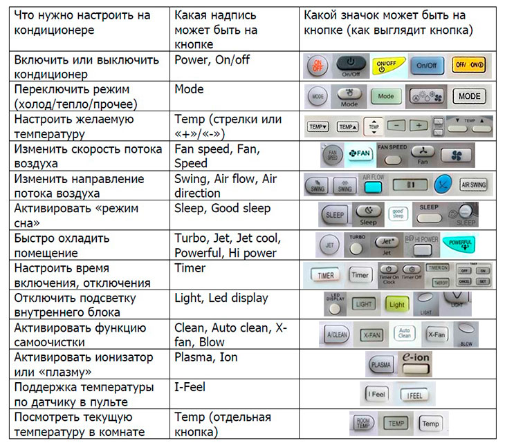
В этой статье мы подробно расскажем, что означают все эти значки на пульте от кондиционера. Разобравшись в этом однажды, вы сможете настроить любую сплит-систему, вне зависимости от бренда.
Кнопки на пульте дистанционного управления
На пульте кондиционера расположено множество кнопок, в которых на первый взгляд непросто разобраться.

Чтобы вы могли проще и быстрее понять их назначение, разделим кнопки на две категории: основные и дополнительные.
Основные обозначения
ON/OFF. Кнопка включения кондиционера. При однократном нажатии аппарат издает характерный звук и загорается светодиод на корпусе.
MODE. Отвечает за выбор режима работы. Основные режимы: COOL (охлаждение воздуха), HEAT (нагрев воздуха). Название выбранного режима отображается на дисплее пульта.
▲/▼ или +/-. Эти кнопки отвечают за выбор температуры, регулировку скорости вентиляции и других параметров.
DRY. Отвечает за включение осушения воздуха. Особенно полезно во влажном климате.
Дополнительные обозначения
На пульте кондиционера есть дополнительные кнопки, которые предназначены для более детальной настройки аппарата. Рассмотрим их подробнее.
ECONO COOL. Отвечает за включение режима охлаждения с пониженным уровнем энергопотребления.
I SAVE. Сохраняет установленные ранее настройки. Очень полезная функция, если вы не хотите при каждом включении настраивать кондиционер заново.
POWERFUL. При нажатии этой кнопки охлаждение/нагрев воздуха осуществляется быстрее и интенсивнее, чем в обычном режиме работы.
TIMER. Отвечает за включение таймера. Настройка таймера может осуществляться кнопками ▲/▼, либо целым рядом дополнительных кнопок: SET (сохранить), DAY (день), CANCEL (отменить), TIME (время), TEMP (температура) и др. Для корректной настройки прочтите инструкцию к вашей модели кондиционера. Она поставляется в комплекте. Также ее можно найти в интернете в электронном формате.
CLOCK. При однократном нажатии появляется возможность настроить время, как на обычных часах. Не путайте с настройкой времени таймера. Настройка времени осуществляется кнопками ▲/▼.
RESET. Сброс всех заданных ранее настроек.
Итоги
Мы рассказали обо всех самых важных кнопках на пульте кондиционера. В зависимости от модели сплит-системы количество кнопок может меняться, но базовый набор всегда одинаковый. Мы рекомендуем изучить инструкцию прежде чем настраивать кондиционер самостоятельно. Желаем удачи!
Приветствую всех на сайте Кондиционерщик! Сегодня я постараюсь написать наиболее понятную инструкцию по управлению бытовой сплит-системой. Надеюсь, что после прочтения каждый пользователь сможет управлять абсолютно любым кондиционером.
Далее берем в руки пульт…
Инструкция к пульту кондиционера – что означают кнопки и значки
Расположу все функции и кнопки в порядке важности от часто нажимаемых к редко используемым.
Возможно, после нажатия кнопки прибор запустится не сразу (это зависит от выбранного режима и температуры).
P.S. Редко попадаются пульты, где режимы включаются не кнопкой Mode, а отдельными кнопками режимов – Cool, Heat, Dry и прочее.
Принцип работы простой – какую температуру настроили на пульте, такую кондиционер будет поддерживать в комнате. Например, если настроили 25, то далее прибор будет стараться поддерживать в помещении +25 градусов (многие ошибочно думают что чем выше цифра, тем холоднее прибор будет дуть – это неверно. )
На дисплее скорость вращения вентилятора отображается в виде шкалы или надписей low/med/high/auto (медленная/средняя/быстрая/автоматическая скорости). При настройке автоматической скорости прибор сам выбирает с какой скоростью в данный момент крутить вентилятор.
Настройка скорости не влияет на значение настроенной температуры (например, если настроили 25 градусов, то они же будут поддерживаться). Эта функция влияет лишь на быстроту охлаждения помещения (быстроту достижения заданной температуры).
Поток у любого кондиционера регулируется в двух направлениях – вверх/вниз и вправо/влево. Вверх/вниз у любого кондиционера регулируется кнопкой на пульте. А вот вправо/влево может быть регулировка и в ручном виде (в этом случае будьте осторожны и лучше выключите кондиционер).
Рекомендую с настройкой направления потока поэкспериментировать, чтобы найти самое безопасное положение (чтобы поток воздуха не дул на людей и на зоны отдых домочадцев – подробнее читайте здесь)
Это были основные кнопки, которые есть абсолютно на каждом пульте. Далее разберем дополнительные, более редкие кнопки и функции.
Осуществляется это благодаря электростатическому полю, создаваемым дополнительным устройством во внутреннем блоке кондиционера. Опция полезная, если она есть на вашей модели, то обязательно пользуйтесь.
Последовательность настройки любого кондиционера
P.S. Если в комнате текущая температура соответсвует настроенной, то кондиционер не будет холодить (или греть в зависимости от режима).
Значки и кнопки на внутреннем блоке сплит-системы
Инструкции по настройке кондиционера в различных режимах
Если вам нужно включить кондиционер в определенном режиме, то на моем сайте уже есть все инструкции:
На этом, пожалуй всё… Если статья была для вас полезна, то оставляйте комментарии!
При помощи данной инструкции вы узнаете как включить и правильно настроить бытовой кондиционер. Любой пульт бытового кондиционера имеет 5 основных кнопок. Расположим их по мере уменьшения значимости в использовании:


Допустим, мы никогда не пользовались кондиционером, или только его установили, или не знаем в каком режиме он настроен (тепло, холод и пр.) Для того, чтобы проверить работоспособность устройства можно следовать следующей инструкции.
Включаем кондиционер на охлаждение:
При настройке некоторых кондиционеров эта цифра может смениться через пару секунд (показывая текущую температуру в комнате);
Это надо знать:
- кондиционер не будет холодить, если температура в комнате достигла настроенной температуры;
- при пользовании пультом всегда направляем его на кондиционер.
Бесплатный совет: при пользовании кондиционером его не надо выключать на ночь или когда вам становится холодно. Лучше настроить оптимальную температуру. Так и вам будет комфортно, и кондиционер работать будет в своем нормальном режиме. Например, ночью можно повысить заданную температуру на 1-2 градуса.
Управление кондиционером осуществляется с пульта ДУ. Он позволяет задать точные настройки. С внутреннего блока можно только включить/выключить прибор и установить режим охлаждения или обогрева. Задать параметры температуры без устройства ДУ невозможно.

Обозначение значков на пульте кондиционера
Количество кнопок и их значения зависит от марки кондиционера. На кнопки наносятся символы или они могут иметь просто надпись.

Итак, что обозначают значки на кондиционере:
- On/off — включает и отключает прибор.
- Снежинка (cool) — охлаждение.
- Солнышко (heat) — обогрев. Есть только у тех моделей, которые поддерживают эту функцию.
- Капля (dry) — осушение. Нужна для удаления лишней влаги из помещения.
- Вентилятор (fan) — меняет скорость вентилятора.
- Четыре стрелочки вбок (swing) — меняют положение шторок, направляя потоки в нужную сторону.
- Звездочка (sleep) — включение ночного режима, при котором прибор начинает работать на малых оборотах.
- Стрелочки вверх/вниз или плюс и минус — позволяют сделать температуру выше/ниже.
- Часы (timer) — устанавливают время работы кондиционера.
- MODE — выбирает режим работы.
- CLOCK — устанавливает время
- LED — включает подсветку дисплея пульта.

Получить консультацию:
Как включить сплит-систему на охлаждение
Чтобы включить этот режим кондиционера, значки нужны следующие:

Чтобы включить систему на отопление, действия такие же. Только ищем значок обогрева на кондиционере: солнышко или heat.

Как работает автоматический режим
Сплит-система контролирует температуру самостоятельно. Если она повышается, прибор включается на охлаждение. В зимний период система будет включаться на обогрев, когда в комнате станет прохладно.
Дополнительные режимы работы кондиционера и значки на пульте
Многие современные модели сплит-систем имеют различные опции, упрощающие управление.

Включается одновременным нажатием всей кнопки temp и mode. Микропроцессор контролирует режим работы сплит-системы, а также состояние блоков. В случае неисправности прибор подает сигнал с помощью комбинации светодиодов на панели внешнего блока.
Ионизация
Управление с помощью Wi-Fi или GSM
В приборе встроен модуль вайфая или GSM, который позволяет управлять кондиционером с помощью мобильного телефона.
Количество функций влияет на итоговую стоимость кондиционера. Зачастую без многих можно спокойно обойтись без ущерба качества охлаждения.
Читайте также:
- Проставки для увеличения клиренса киа
- Солярис руль крутится сам
- Штраф за оставление авто на дороге
- Вольво с40 отзывы владельцев недостатки
- Иммобилайзер приора признаки неисправности