-
Contents
-
Table of Contents
-
Bookmarks
Quick Links
INSTRUCTION MANUAL
LPD FM HANDHELD TRANSCEIVER
i4088E
Related Manuals for Icom IC-4088E
Summary of Contents for Icom IC-4088E
-
Page 1
INSTRUCTION MANUAL LPD FM HANDHELD TRANSCEIVER i4088E… -
Page 2
FOREWORD Thank you for purchasing the IC-4088E LPD (Low Power De- vice) FM transceiver. This LPD FM transceiver meets the Euro- pean LPD specification (EN 300 220). This transceiver is designed for those who require top-grade quality, performance and outstanding reliability under the most demanding conditions. -
Page 3: Supplied Accessory
10 different ringing tones are available. (p. 18) SUPPLIED ACCESSORY • Belt clip ………………………………… 1 Icom, Icom Inc. and the are registered trademarks of Icom Incor- porated (Japan) in the United States, the United Kingdom, Germany, France, Spain, Russia and/or other countries.
-
Page 4: Important
IMPORTANT READ ALL INSTRUCTIONS carefully and completely before using the transceiver. SAVE THIS INSTRUCTION MANUAL— This instruction man- ual contains important operating instructions for the transceiver. PRECAUTION RWARNING! NEVER hold the transceiver so that the antenna is very close to, or touching exposed parts of the body, especially the face or eyes, while transmitting.
-
Page 5
–10°C or above +55°C. The use of non-Icom battery packs/chargers may impair trans- ceiver performance and invalidate the warranty. Even when the transceiver power is OFF, a slight current still flows in the radio. -
Page 6: Table Of Contents
TABLE OF CONTENTS FOREWORD …………………………………………………………………… i SUPPLIED ACCESSORY ……………………………………………………… ii IMPORTANT …………………………………………………………………… iii PRECAUTION ……………………………………………………………… iii–iv TABLE OF CONTENTS ……………………………………………………… v 1 PREPARATION …………………………………………………………… 1 I Belt clip attachment ……………………………………………………… 1 I Battery installation ……………………………………………………… 1 2 PANEL DESCRIPTION ………………………………………………… 2–4 I Switches, controls, keys and connectors …………………………………
-
Page 7: Preparation
PREPARATION I Belt clip attachment Attach the belt clip using the supplied screw. Conveniently attaches to a belt. I Battery installation Install 3 R6 (AA) size alkaline cell batteries or the optional BP-202 as illustrated below. BATTERY PACK qRemove the battery case cover from the transceiver.
-
Page 8: Panel Description
PANEL DESCRIPTION I Switches, controls, keys and connectors Antenna Function display (p. 4) Microphone Speaker…
-
Page 9
PANEL DESCRIPTION q EXTERNAL SPEAKER AND MICROPHONE JACKS Connect an optional speaker-microphone or headset, if desired. w VOLUME CONTROL [VOL] Rotate clockwise to increase and counterclockwise to decrease vol- ume. e PTT SWITCH [PTT] Push and hold to transmit; release to receive. r MODE SWITCH [MODE] ➥… -
Page 10: I Function Display
PANEL DESCRIPTION I Function display q KEY LOCK INDICATOR Appears during the key lock function ON. w BUSY INDICATOR Appears while receiving a signal or when the squelch is open. e VOICE SCRAMBLER INDICATOR Appears while the voice scrambler function is in use. r AUTO POWER OFF INDICATOR Appears while the auto power off function is ON.
-
Page 11: Battery Charging
AVOID over charging— The BP-202 can be charged during opera- tion when the AC adapter or the optional cigarette lighter cable is connected. To prevent over charging, the IC-4088E has charging timer that automatically disconnecting the charging line electronically after 15 hours from charging. However, the charging timer will reset and start charging again when disconnect then re-connecting the AC adapter or CP-18E more than 1 min.
-
Page 12: I Charging Connections
BATTERY CHARGING I Charging connections Regular charging with the BC-149D, CP-18E ➥ Connect the optional BC-149D or CP-18E AC ADAPTER CIGARETTE to [DC 6V]. LIGHTER CABLE • Charging period: approx. 15 hours Optional CP-18E Cigarette lighter cable with DC-DC converter to cigarette lighter socket to [DC 6V]…
-
Page 13
BC-119N. w Insert the battery pack, either by itself or attached to the trans- ceiver, into the charger. BP-202 IC-4088E Turn the power OFF! When the installed Ni-Cd battery is nearly exhausted and the function display… -
Page 14: Basic Operation
BASIC OPERATION I Power ON ➥ Push [PWR] for 1sec. to turn the power ON. • “ ” and operating channel num- ber appear on the display. [PWR] I Adjusting the volume q Push and hold [MODE] for [VOL] 1sec. to open the squelch. •…
-
Page 15: I Selecting The Operating Channel
BASIC OPERATION I Selecting the operating channel Push [Y] or [Z] keys several times until the desired operating channel number appears on the display. • While pushing and holding [Y] or [Z] keys, the displayed channel changes continuously until chan- nel number “1”…
-
Page 16: Receive And Transmit
RECEIVE AND TRANSMIT q Select the desired operating channel with [Y]/[Z]. When a signal is received: • “ ” indicator appears on the display. • Squelch opens and audio is emitted from the speaker. — Further adjustment of [VOL] may be necessary at this point. w Push and hold [PTT] to transmit then speak into the microphone.
-
Page 17
RECEIVE AND TRANSMIT ✔ Talk Range The IC-4088E is designed to maximize performance and improve transmission range in the field. However, the single most impor- tant factor in transmit range (talk power) is the surrounding envi- ronment. These radios are “line of sight” radios and as such, transmission range are influenced by the degree to which you can “see”… -
Page 18: Group Mode (Ctcss)
GROUP MODE (CTCSS) I Setting the group code The IC-4088E is equipped with 38 group codes. Group mode oper- ation provides communication with silent standby since you will only receive calls from group members using the same group number. First of all, set the same group code number for all group member’s transceivers.
-
Page 19
Note that CTCSS group mode is not private—any- one can receive your calls. The IC-4088E is equipped with 38 tone codes for CTCSS GROUP MODE use. Selecting a code applies it to all 69 operating channels. Each push of [PTT] superimposes your group code over your trans- mit signal;… -
Page 20: Scan Function
SCAN FUNCTION Scanning is an efficient way to locate signals quickly over all chan- nels. Select scan resume condition in advance, using Initial Set Mode (p. 17) CH 1 CH 2 CH 69 CH 3 CH 5 CH 4 D Starting the scan ➥…
-
Page 21: Ring Functions
RING FUNCTIONS I Smart-Ring The ring function has an answer back feature. This allows confir- mation of whether or not a call has reached the receiving party even if the operator is temporarily away from the transceiver. q Set the same group channel number for all of the group transceivers.
-
Page 22: Other Functions
OTHER FUNCTIONS I Voice scrambler function The voice scrambler function provides communication privacy. q Push [MODE] twice to select voice scram- bler setting mode. • “Sr-” appears on the display. w Push [Y]/[Z] to turn the function ON and OFF. •…
-
Page 23
OTHER FUNCTIONS D Beep tones ON/OFF Confirmation beep tones normally sound when a key is pushed. These can be turned ON or OFF. ON (on) : Emits confirmation beep. OFF (oF) : No confirmation beep. D D Scan resume type Select the scan resume type from timer scan and pause scan. -
Page 24
Ring tone is selectable with 10 different indi- vidual sounds. D D LCD backlight The IC-4088E has LCD backlight light for nighttime operation, and the lighting condition can be selected to suits a specific preference, from Auto, ON and OFF. -
Page 25: I Lock Function
OTHER FUNCTIONS I Lock function This function electronically locks all keys and switches to prevent accidental channel changes and function access. ➥ Continue to hold [PWR] down for 2 sec. after power ON to turn the lock function ON and OFF. •…
-
Page 26: I Ats (Automatic Transponder System)
NOTE: Above setting is for the calling station only. A called party automatically sends an answer back signal without any preset- tings. All IC-4088E’s operating on the same operating channel will answer back to the call in the surroundings communications area.
-
Page 27: I Optional Hm-75A Functions
OTHER FUNCTIONS I Optional HM-75A functions The optional HM-75A allows remotely selected operating channels, open the squelch, etc. The switches on the HM-75A function as fol- lows. CAUTION: When connecting the HM-75A to the transceiver, make sure that power to the transceiver is turned OFF, other- wise the transceiver may malfunction.
-
Page 28: Specifications
SPECIFICATIONS • No. of operating Ch. : 69 (simplex; 433.075–434.775 MHz) • Mode : FM (F3E) • Frequency stability : ±2.5 kHz • Frequency resolution : 25 kHz • Power supply requirement : 3 AA (R6) alkaline, BP-202, BC-149D or CP-18E (negative ground) •…
-
Page 29
SPECIFICATIONS D Channel number and group number Use this page to record a group operating channel number (see p. 9) and group code number (p. 12) for your reference. Operating channel number Group code number ï Channel frequency list Freq.(MHz) Freq.(MHz) Freq.(MHz) 433.075… -
Page 30: Options
OPTIONS BP-202 Ni-Cd BATTERY PACK 3.6V/700 mAh Ni-Cd battery pack. BC-119N + AD-105 DESKTOP CHARGER DESKTOP CHARGER ADAPTER Rapidly charges battery pack in 1 to 1.5 hrs. An AC adapter is packed with the BC-119N. The AD-105 must be used with the BC-119N for charging the battery pack.
-
Page 31
EN 50 371: 2002 Signature D D ABOUT CE The IC-4088E comply with the essential requirements of the European Radio and Telecommunication Terminal Directive 1999/5/EC. This warning symbol indicates that this equipment operates in non- harmonised frequency bands and/or may be subject to licensing condi- tions in the country of use. -
Page 32
<Intended Country of Use> BEL I ITA A-6222D-1EX-w Printed in Japan 1-1-32 Kamiminami, Hirano-ku, Osaka 547-0003, Japan © 2002–2003 Icom Inc.
Instruction Manual Download
| Model | IC-4088E |
|---|---|
| Document | Instruction Manual |
| Note | |
| File size | 967KB |
About this Download Service.
Icom Inc. would like to advise User’s of the following regarding this download service for User Manuals and Service Manuals. If you agree to the following, push the AGREE button below to proceed.
The following apply to this download service.
- The ownership, copyright and other rights pertaining to all User Manuals and all of the contents of this site are the sole property of Icom Inc. Individual use of the Manuals is permitted, but the following are strictly prohibited.
- Reproduction, lease, alteration, public distribution or the creation of means to publicly distribute the Manuals.
- The transfer of the Manuals either for compensation or no compensation to a third party.
- The use of the Manuals either for profit or non-profit commercial use.
- The transfer of any and all photos, illustrations, data etc. in the Manuals.
- Do not alter in any way the Manuals or any of the contents of this site. Icom Inc. accepts no responsibility for faults and/or damages/losses caused as a result of alterations made by User’s.
- The content of the Manuals on this site, including legal content, specifications, addresses and phone numbers were correct at the time of publication and sale of the product. However, changes may have been made to update any change in such content.
- Icom Inc. reserves the right to change the content of the Manuals any time, and it is possible that in some cases the content of the Manuals on this site may differ slightly to that of the Manuals included in the product package at the time of purchase.
- The addition of notices, corrections and quick manuals to the product packaging is sometimes made. In some case, such additions to the content of the Manuals may not appear on this site.
- Reproduction of the content of the Manuals is permitted only when such reproduction is for the individual use by the person downloading the Manuals, and in accordance with the conditions of this download service.
- Icom Inc. accepts no responsibility, and is indemnified from any damages or losses caused as a result of the User using or not being able to use this download service.
- Icom Inc. reserves the right to stop, cancel or make changes to this download service without notice or obligation.

1
ВВЕДЕНИЕ
Поздравляем Вас с тем, что Вы остановили свой выбор на FM трансивере IC-4088E
LPD (пониженное энергопотребление). Этот FM трансивер LPD отвечает требованиям
Европейской спецификации на LPD-устройства (EN 300 220). Ваш трансивер
разработан специально для тех, кто хочет иметь отменное качество связи при работе в
самых неблагоприятных условиях.
ОТЛИЧИТЕЛЬНЫЕ ЧЕРТЫ
o
o
Упрощённый порядок приобретения и регистрации.
o
o
Имеется функция маскиратора речи (скремблера) для ведения скрытых
переговоров.
o
o
Через разъём DC-IN можно как питать трансивер от внешнего
источника, так и заряжать от него аккумуляторную батарею.
(Потребуется приобретаемый отдельно сетевой адаптер ВС-149D или кабель СР-
18Е).
o
o
Доступны все 69 LPD каналов.
o
o
Рабочие каналы можно объединять в 38 удобных групп.
АТС (Автоматическая Система проверки Дальности действия)
Эта полезная функция позволяет автоматически определять – находится ли
нужная радиостанция в пределах радиуса Вашего действия с выводом
результатов измерения на функциональный дисплей.
В дополнение к этому имеется система ручной проверки дальности действия при
работе в групповом режиме “GROUP MODE”, позволяющая проверять
доступность радиостанций в выбранной группе. В этом режиме трансивер
сообщает результаты измерений звуковыми сигналами.
ВСЕПОГОДНОЕ ИСПОЛНЕНИЕ*
Всепогодное исполнение трансивера означает, что им можно пользоваться в
ненастную погоду.
* Корпус трансивера отвечает требованиям класса 4 стандарта JIS по степени
водонепроницаемости.
РЕЖИМ РАБОТЫ В ГРУППЕ (ВСТРОЕННАЯ СИСТЕМА CTCSS: субтональное
шумоподавление)
Кодирующее и декодирующее устройства CTCSS являются стандартными,
обеспечивающими в отсутствие нужного суб-тонального сигнала CTCSS
мониторинг частоты с отключённым звуковым сопровождением – звук из
динамика раздаётся только тогда, когда принимается требуемый суб-тональный
сигнал CTCSS. Это очень полезная функция при проведении групповых связей.
Имеется возможность установки 38 различных суб-тональных частот CTCSS.
2 разновидности «Звуковых Сигналов», когда Вас вызывают
У трансивера имеются две разновидности звуковых сигналов, напоминающих
телефонные звонки, издаваемых им, когда Вас вызывают – “Smart-Ring” и “Call-
Ring”. При этом при составлении мелодии имеется возможность выбирать из 10-
ти различных звуковых комбинаций.
![]()
INSTRUCTION MANUAL
LPD FM HANDHELD TRANSCEIVER
i4088E

FOREWORD
Thank you for purchasing the IC-4088E LPD (Low Power Device) FM transceiver. This LPD FM transceiver meets the European LPD specification (EN 300 220). This transceiver is designed for those who require top-grade quality, performance and outstanding reliability under the most demanding conditions.
D FEATURES
Free of user-license and applications
Voice scrambler function for communication privacy
External DC-IN jack for both operation and battery charging
(Optional BC-149D or CP-18E is required)
All 69 LPD channels are available
38 convenient group channels
■ ATS (Automatic Transponder System)
This convenient function automatically checks station availability within the operating range, and alerts you via function display indication. (p. 20)
In addition, a manual transponder is also available for “GROUP MODE” operation to check availability of stations in a specified group within the operating range. In this case, the transceiver alerts you via beeps. (p. 15)
■ WEATHER-RESISTANT* CONSTRUCTION
Weather-resistant* construction is employed, and this unit can be used in a wide range of applications.
*Meets JIS water-protection specification grade 4.
i
■ GROUP MODE (BUILT-IN CTCSS: Continuous Tone
Coded Squelch System)
CTCSS encoder/decoder are standard, providing quiet stand-by. Audio (voice) signals are output only when a signal with matched CTCSS tone signal is received. This is very helpful for group communications. In addition, 38 different CTCSS frequencies are available. (p. 12)
■ 2 types of “Ring” function
The “Smart-Ring” function and the “Call-Ring” function are available for smart and simple station calls providing a telephonestyle ring when called. 10 different ringing tones are available. (p. 18)
SUPPLIED ACCESSORY
• Belt clip ………………………………… 1
Icom, Icom Inc. and the 
 are registered trademarks of Icom Incorporated (Japan) in the United States, the United Kingdom, Germany, France, Spain, Russia and/or other countries.
ii

IMPORTANT
READ ALL INSTRUCTIONS carefully and completely before using the transceiver.
SAVE THIS INSTRUCTION MANUAL— This instruction manual contains important operating instructions for the transceiver.
PRECAUTION
RWARNING! NEVER hold the transceiver so that the antenna is very close to, or touching exposed parts of the body, especially the face or eyes, while transmitting. The transceiver will perform best if the microphone is 5 to 10 cm away and the transceiver is vertical.
RWARNING! NEVER operate the transceiver with a headset or other audio accessories at high volume levels. Hearing experts advise against continuous high volume operation. If you experience a ringing in your ears, reduce the volume or discontinue use.
NEVER attempt to charge alkaline cell batteries. Be aware that external DC power connections will charge batteries inside the battery case. This will damage not only the battery case but also the transceiver.
DO NOT push the PTT when not actually desiring to transmit.
iii

PRECAUTION— continued
USE the optional AC adapter or cigarette lighter cable only for both operating the transceiver and charging the battery. Other manufacturer’s AC adapter, cigarette lighter cable or DC power cable with external power supply may damage the transceiver.
Place the unit in a secure place to avoid inadvertent use by children.
DO NOT operate the transceiver near unshielded electrical blasting caps or in an explosive atmosphere.
AVOID using or placing the transceiver in direct sunlight or in areas with temperatures below –10°C or above +55°C.
The use of non-Icom battery packs/chargers may impair transceiver performance and invalidate the warranty.
Even when the transceiver power is OFF, a slight current still flows in the radio. Remove the alkaline battery cells or battery pack from the transceiver when not using it for a long time. Otherwise, the installed batteries will become exhausted.
When the battery voltage becomes below 3.24 V, the performance of the transceiver cannot be guaranteed due to the regulation.
iv

TABLE OF CONTENTS
FOREWORD …………………………………………………………………… i SUPPLIED ACCESSORY……………………………………………………… ii IMPORTANT …………………………………………………………………… iii PRECAUTION ……………………………………………………………… iii–iv TABLE OF CONTENTS ……………………………………………………… v
1 PREPARATION …………………………………………………………… 1
■Belt clip attachment ……………………………………………………… 1
■Battery installation ……………………………………………………… 1
2 PANEL DESCRIPTION ………………………………………………… 2–4
■Switches, controls, keys and connectors ……………………………… 2
■Function display ………………………………………………………… 4
3 BATTERY CHARGING ………………………………………………… 5–7
■Battery caution …………………………………………………………… 5
■Charging connections …………………………………………………… 6
4 BASIC OPERATION …………………………………………………… 8–9
■Power ON ………………………………………………………………… 8
■Adjusting the volume …………………………………………………… 8
■Selecting the operating channel………………………………………… 9
5RECEIVE AND TRANSMIT ………………………………………… 10–11
6GROUP MODE (CTCSS) …………………………………………… 12–13
■Setting the group code ………………………………………………… 12
7SCAN FUNCTION ………………………………………………………… 14
8RING FUNCTIONS ……………………………………………………… 15
■Smart-Ring ……………………………………………………………… 15
■Call-Ring ………………………………………………………………… 15
9OTHER FUNCTIONS ………………………………………………… 16–21
■Voice scrambler function ……………………………………………… 16
■Initial set mode ………………………………………………………… 16
■Lock function …………………………………………………………… 19
■Low battery indicator …………………………………………………… 19
■Auto power save………………………………………………………… 19
■ATS (Automatic Transponder System) ……………………………… 20
■Resetting the transceiver ……………………………………………… 20
■Optional HM-75A functions …………………………………………… 21
10SPECIFICATIONS …………………………………………………… 22–23
11OPTIONS…………………………………………………………………… 24
12CE …………………………………………………………………………… 25
v

BATTERY PACK
|
PREPARATION |
1 |
|
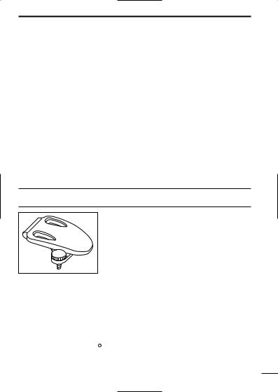
■ Belt clip attachment |
1 |
Attach the belt clip using the supplied screw. Conveniently attaches to a belt.
■ Battery installation
Install 3 R6 (AA) size alkaline cell batteries or the optional BP-202 as illustrated below.
qRemove the battery case cover from the transceiver. wInstall 3×R6 (AA) size alkaline cell batteries or BP-
202.
• Be sure to observe the correct polarity.
BP-202

 Alkaline cells
 NOTE: Keep battery contacts clean. It’s good idea to clean bat-
  tery terminals once a week.
1
2 PANEL DESCRIPTION
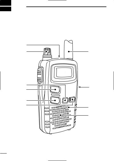
■Switches, controls, keys and connectors
q
 Function e
 display
(p. 4)
|
r |
i |
|
|
t |
||
|
y |
||
|
u |
Microphone |
|
|
Speaker |
2

PANEL DESCRIPTION 2
q EXTERNAL SPEAKER AND MICROPHONE JACKS
Connect an optional speaker-microphone or headset, if desired.
2
w VOLUME CONTROL [VOL]
Rotate clockwise to increase and counterclockwise to decrease volume.
e PTT SWITCH [PTT]
Push and hold to transmit; release to receive.
r MODE SWITCH [MODE]
Push to enter and select set mode for group (p. 12) and voice scrambler code. (p. 16)
Push and hold for 1 sec. to turn the monitor function ON and OFF. (p. 
t CHANNEL UP SWITCH [Y]
Push to increment the operating channel.
Push and hold to increment the operating channel continuously.
While scanning, changes scanning direction. (p. 14)
y CHANNEL DOWN SWITCH [Z]
Push to decrement the operating channel.
Push and hold to decrement the operating channel continuously.
While scanning, changes scanning direction. (p. 14)
u POWER SWITCH [PWR]
Push to turn the power ON.
Push and hold this key to toggle the key lock function ON/OFF. (p. 19)
iEXTERNAL DC IN JACK [DC 6V] (p. 6)
Connects the optional AC adapter or cigarette lighter cable for both operation and battery charging.
3
2 PANEL DESCRIPTION
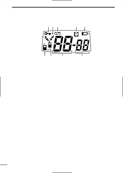
■ Function display
q KEY LOCK INDICATOR
Appears during the key lock function ON. w BUSY INDICATOR
Appears while receiving a signal or when the squelch is open. e VOICE SCRAMBLER INDICATOR
Appears while the voice scrambler function is in use. r AUTO POWER OFF INDICATOR
Appears while the auto power off function is ON. t LOW BATTERY INDICATOR
Appears or blinks when the battery decreases to a specified level. y GROUP NUMBER INDICATOR
Indicates the selected group number during the group function ON. u CHANNEL NUMBER INDICATOR
Indicates the selected operating channel number. i POWER ON INDICATOR
Appears while the power is ON. o ANSWER BACK INDICATOR
Appears when you and your group are in the conversation area.
Blinks when you or your group is out of the conversation area.
!0TRANSMIT INDICATOR
Appears during PTT ON.
4
 Loading…
Icom IC-4088E Transceiver PDF User Guides and Manuals for Free Download: Found (2) Manuals for Icom IC-4088E Device Model (Service Manual, Instruction Manual)
More Transceiver Device Models:
-
Kenwood
TM-481A
SERVICE MANUALThis product complies with the RoHS directive for the European market.This product uses Lead Free solder.© 2011-12 PRINTED IN JA PANB53-7001-00 (Y) 63TM-481A430MHz FM TRANSCEIVERKey top(K29-9497-01)Modular jack (MIC)(E58-0535-05)Panel assy(A62-1189-03)Knob (VOL)(K29-9498-03)Knob (ENC)(K29-9499-03)4DISASS …
TM-481A Transceiver, 50
-
Alinco
DJ-A10
VHF/UHF FM HANDHELD TRANSCEIVERSDJ-A10 136~174MHzDJ-A40 400~470MHz These VHF/UHF handheld transceivers pack a lot of performance into a MIL-spec* rugged polycarbonate bodies. Designed to resist splash and dust*, the DJ-A10/A40 features professional grade specs such as 1W audio output, 2.5ppm frequency stability, capa …
DJ-A10 Transceiver, 2
-
PocketWizard
MiniTT1
Quick GuideMiniTT1™/FlexTT5™ for Canon340.00 – 354.00 MHz, US FCC/IC433.42 – 434.42 MHz, CE2 FlexTT5™CONFIGURATION:Your new PocketWizard radio runs on verysophisticated software we call ControlTL which can be configured to your specific needs using the PocketWizard Utility.You can download this utility atwww …
MiniTT1 Transceiver, 12
-
Motorola
MTP810 EX
www.motorola.comwww.motorola.com12345657891011101213131415716171819MTP810 ExQuick Start GuideControls and IndicatorsGetting StartedInstalling the BatteryAttaching the AntennaUnlocking the TerminalHow to Hold Your TerminalLooking After Your TerminalBattery installing must occur only in non-hazardous areas.Remove the bat …
MTP810 EX Two-Way Radio, 2
Recommended Documentation: