-
Contents
-
Table of Contents
-
Bookmarks
Quick Links
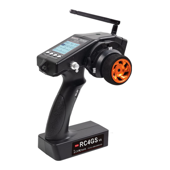
RC4GS
V3
Digital 5 Channels Proportional RC System
Instruction Manual
Adaptable to RC Cars/Boats/Robot
CE FCC RoHS
* Please be kindly noted that this manual will be updated regularly and please visit RadioLink official website
www.radiolink.com to download the latest version.
Related Manuals for RadioLink RC4GS V3
Summary of Contents for RadioLink RC4GS V3
-
Page 1
RC4GS Digital 5 Channels Proportional RC System Instruction Manual Adaptable to RC Cars/Boats/Robot CE FCC RoHS * Please be kindly noted that this manual will be updated regularly and please visit RadioLink official website www.radiolink.com to download the latest version. -
Page 2
RadioLink Electronic Limited www.radiolink.com Thank you for choosing RadioLink 2.4 GHz 5CH radio — RC4GS V3. To fully enjoy the benefits of this product and ensure safety, please read the manual carefully and set up the device as instructed steps. -
Page 3
(2) Changes or modifications not expressly approved by the party responsible for compliance could void the user’s authority to operate the equipment. Packing list Items RC4GS V3 Transmitter R6FG Receiver User Manual Packing Box… -
Page 4: Table Of Contents
RadioLink Electronic Limited www.radiolink.com Contents I. RC4GS V3 Remote Control System ……………………5 1.1 Transmitter …………………………5 1.2 Receiver R6FG(Standard Pack) ………………….. 6 1.2.1 R6FG Specification ……………………..6 1.2.2 Receiver Installation and Binding ………………….7 1.2.3 Working Mode ……………………….7 1.2.4 Gyro Setup ………………………..8 1.2.5 Signal/RSSI Real-time Return …………………..
-
Page 5
3.5 Dual Rate Function on RC4GS V3 ………………….39 3.6 EPA Function on RC4GS V3 ……………………39 3.7 Set Different ALARM for 30 Different Models on RC4GS V3 …………..39 3.8 ID Seed Function on RC4GS V3 ………………….39 3.9 Cruise Control Function on RC4GS V3 ………………..39 3.10 Head Track Function on RC4GS V3 …………………39… -
Page 6: Rc4Gs V3 Remote Control System
RadioLink Electronic Limited www.radiolink.com I. RC4GS V3 Remote Control System RC4GS V3, 12ms only from transmitter to the receiver, thus provide control synchronous and perfect performance. The same FHSS spread spectrum and 16 channels pseudo random frequency sequence hopping of AT9S makes RC4GS V3 have superior anti-interference ability both at the same frequency band and different frequency bands.
-
Page 7: Receiver R6Fg(Standard Pack)
Compatible Receiver: R6FG(Standard), R8FG, R7FG, R6F, R8EF, R8F, R4FGM, R4F Battery Tray Dimension: 89*59*25mm (3.5*2.32*0.98″) 1.2 Receiver R6FG(Standard Pack) Receiver packed with RC4GS V3 is R6FG, 2.4GHz 6 channels, gyro integrated and high voltage servo supported. 1.2.1 R6FG Specification Size: 35*20*13mm (1.38*0.79*0.51″) …
-
Page 8: Receiver Installation And Binding
Note 1. The binding between your R6FG and RC4GS V3 is already complete by default. Just need to make sure there is the solid light of R6FG and the signal tower in the transmitter. 2. NO gyro by default as factory setting. Since integrated gyro in R6FG will self-check, it is very important to remain R6FG still when powering it on.
-
Page 9: Gyro Setup
ENTER to (dis)activate the warning and set the RSSI warning value. Note: The ‘RATE: RPM’ and ‘T: NULL’ telemetry functions are still under development. If there are new developments, we will announce them to the RadioLink official website as soon as possible.
-
Page 10: Telemetry Of Model Battery And Receiver Voltage
RadioLink Electronic Limited www.radiolink.com 1.2.6 Telemetry of Model Battery and Receiver Voltage When done binding with R8FG, R7FG or R8F receiver, besides the telemetry of RSSI, receiver voltage, model battery voltage (maximum up to 8S lithium battery, 33.6V) can also be returned in real time. Users can personalize the warning value of low model battery voltage depending on the actual needs.
-
Page 11: Rc4Gs V3 Functions
When binding is done, there’s signal tower on top middle of the screen. As there’s no amplifier module added on R6FG, the signal telemetry from receiver is about 80m(262.5ft). If the distance is longer than 80m, the signal tower may disappear but the control range of RC4GS V3 is as long as 400m(1312ft).
-
Page 12: Language «Language
Eg. V6.6.7 in above picture. 2.3 Model Select «MODEL» RC4GS V3 can store model memories for 30 models. Use this function to call a new model. Each model can independently set the parameters of each function.
-
Page 13: End Point Adjust «Epa
RadioLink Electronic Limited www.radiolink.com simultaneously and holding them down for one second), press “Enter” key once, the Model select function will be chosen. (2) Press “Enter” button, the current active model will be blinking. (3) To activate a different model by pressing “Dec(-)” or “Inc(+)” button until the desired model blinks.
-
Page 14: Steering Exponential «Stexp
RadioLink Electronic Limited www.radiolink.com “Dec(-)” or “Inc(+)” button to adjust the rate value. After setting, press «Enter» key, the rate value stops flashing, and the channel rate value is set. (4) Press «Exit» to return to the home page. 2.5 Steering Exponential «STEXP»…
-
Page 15: Throttle Exponential «Thexp
RadioLink Electronic Limited www.radiolink.com for one second), press “Inc(+)” button four times to chose STSPD function. (2) Press“Enter” button to get into STSPD function interface, press “Dec(-)” or“Inc(+)” button to select setup item, then press “Enter” key and the initial value of selected setup item will blink.
-
Page 16: Throttle Speed «Thspd
RadioLink Electronic Limited www.radiolink.com Adjustment method for EXP curve Setup items MODE: EXP turn on or turn off RATE: EXP rate Adjustment range MODEL: OFF/ON RATE: -100 ~ 0 ~ +100 1. Enter the function menu and use “Dec(-)” or “Inc(+)” button to access THEXP function, then select the “FWD-EXP”…
-
Page 17
RadioLink Electronic Limited www.radiolink.com OFF: Speed1 or speed2 can be selected. OFF means shut down the throttle speed function Adjustment method for SPEED1 Setup items MODE: Speed type selection ALL: Speed adjustment Adjustment range 0~100 (each direction) At 100, there is no delay (1) Enter the function menu and use “Dec(-)”or“Inc(+) ”… -
Page 18: Function «A.b.s
RadioLink Electronic Limited www.radiolink.com setup item will blink. Use “Dec(-)” or “Inc(+)” button to adjust the value. (Note: In the interface of adjusting the value, return to the initial value (the initial value of LOW and HIGH is “100”, the initial value of TGP1 is “30”) by pressing “Dec(-)” and “Inc(+)” buttons simultaneously for about 1 second.) Press “Enter”…
-
Page 19
RadioLink Electronic Limited www.radiolink.com (Note: In the interface of adjusting the value, return to the initial value «50» by pressing “Dec(-)” and “Inc(+)” buttons simultaneously for about 1 second.) Press “Enter” button, the adjusted value stops blinking, now the value has been set. -
Page 20: Throttle Acceleration «Accel
RadioLink Electronic Limited www.radiolink.com (5) Cycle duty ratio setup Select setting item «DTY» by pressing “Dec(-)” or “Inc(+)” button, then press“Enter” key and the initial value of “DTY” will blink. Use “Dec(-)” or “Inc(+)”button to adjust the duty ratio. (Note: In the interface of adjusting the value, return to the initial value «0» by pressing “Dec(-)” and “Inc(+)”…
-
Page 21: Idle-Up «Idlup
RadioLink Electronic Limited www.radiolink.com Setup item FWRD: Forward side acceleration amount BRAK: Brake side acceleration amount Throttle acceleration adjustment Enter the function menu and use “Dec(-)” or “Inc(+)” button to access ACCEL function, then press “Enter” button to get into ACCEL function interface.
-
Page 22: Throttle Lock «Th-Lock
RadioLink Electronic Limited www.radiolink.com (1) Enter the function menu and use “Dec(-)” or“Inc(+) ” button to access IDLUP function. (2) Press “Enter” button to get into IDLUP function interface. (3) Press “Enter” key, and the initial value of RATE will blink. Use“ Dec(-) ” or “Inc(+)” button to adjust the value.
-
Page 23: Channel Reverse «Reverse
RadioLink Electronic Limited www.radiolink.com CH5: -100~0~+100 Initial value : 0 (1) Enter the function menu and use “Dec(-)”or “Inc(+)” button to access SUBTRIM function. (2) Press “Enter” button to get into SUBTRIM function interface. (3) Use “Dec(-)” or “Inc(+)” button to select ST channel, press “Enter”key, and the initial value of ST will blink.
-
Page 24: Brake Side Adjustment «Atl
RadioLink Electronic Limited www.radiolink.com Dual Rate Setting: (1) Long press «Exit» and «Enter» button simultaneously for one second to enter the function menu of RC4GS V3. Press «Inc(+)» button at the bottom of the screen to move the cursor to «13. D/R», and then press » Enter”…
-
Page 25: Programmable Mixes «Pmix01/02
RadioLink Electronic Limited www.radiolink.com 2.16 Programmable Mixes «PMIX01/02» Programmable mixes between arbitrary channels These functions allow you to apply mixing between the steering, throttle, CH3, CH4 and CH5. PMIX01 setting is the same with PMIX02 Programmable Mixes «PMIX» MXMD:Mix mode Enter the function menu and use“Dec(-)”or “Inc(+)”…
-
Page 26: Mix Control Setup
RadioLink Electronic Limited www.radiolink.com channel. ST: «LEFT»; TH: «FWRD»; CH3:»UP») by pressing “Dec(-)” or “Inc(+)” button. Press “Enter” key, the initial value of «LEFT», «FWRD», or «UP» will blink, Use “Dec(-)” or “Inc(+)” button to adjust the left, forward, or up side mixing amount.
-
Page 27
1. Throttle Reverse:NOR-REV Hold RC4GS V3 as the below pic. Normally, pull the throttle, the right track should be moving forward while push the throttle and the right track should be backward. Pull the throttle,right track moves forward,left track remains still If pulling the throttle and the left track moves backward;… -
Page 28
* If the throttle reverse is correct, skip this throttle reverse setup. 2. Steering Reverse:NOR/REV Hold RC4GS V3 as the below pic. Normally, if turn the wheel right/clockwise, the left track should be moving forward while turn the wheel left/anticlockwise and the left track should be backward. -
Page 29
RadioLink Electronic Limited www.radiolink.com Mix Control Setup 1. Throttle mix steering:Tracked vehicles moving forward/backward As tracked vehicles moving forward/backward is controlled by throttle, throttle leads steering in the mix control. That is, Master-Throttle, Slave-Steering. Please refer to the “button operation”and get into below interface to complete the setup. -
Page 30: Auxiliary Channel «Aux-Ch
2.17 Auxiliary Channel «AUX-CH» In addition to the two basic channels of the steering channel (channel 1) and the throttle channel (channel 2), RC4GS V3 also has three auxiliary channels, all of which can be customized to assign control switches.
-
Page 31: Model Name «Name
Factory default name: MODEL1 (1) Long press «Exit» and «Enter» button simultaneously for one second to enter the function menu of RC4GS V3. Press «Inc(+)» button at the bottom of the screen to move the cursor to «18. NAME». (2) Press “Enter” button to get into NAME function interface, the first character of current name will blink, and the blinking character can be reset.
-
Page 32: Gyro Sensitivity «Gyro
RadioLink Electronic Limited www.radiolink.com Transmitter voltage is low Receiver voltage is low RC model battery voltage is low The RSSI alarm value is turned off by default. Users can set it as the RSSI value corresponding to the farthest safe distance of the actual control. For example, the farthest remote control distance is 400m, the corresponding RSSI value is -85dBm, then you can set the RSSI alarm value as -85dBm.
-
Page 33: Subsidiary Id «Id Seed
ID codes of this transmitter. For example, RC4GS V3 has completed the binding with 10 different boats and the setup of respective parameters. Turn on the ID SEED function, select ID.1 boat and drive it to the central of water but it stops working unexpectedly.
-
Page 34: Dsc Port Setting «Dsc
Head track mode: If you need to connect FPV goggles with head track function to the DSC port of RC4GS V3, please set the mode to: head track. Then directly insert one end of the standard audio head of the FPV goggles into the DSC port of the remote control, and the other end into the Track Out port of the FPV goggles.
-
Page 35: Timer Setting «Timer
When the DSC mode is selected as head track, the DSC port of RC4GS V3 outputs in channel 5 and channel 6 by default. Then connect the roll servo and pitch servo used to control the pan-tilt to the pins of R6FG receiver in channel 5 and channel 6, and then swing the FPV goggles up and down or left and right, and the servos of the corresponding channel will swing accordingly.
-
Page 36: Factory Reset «Reset
RadioLink Electronic Limited www.radiolink.com Note: 1. When triggering the timing function, please do not put the switch in the stop or reset position, otherwise the timing function cannot be activated. 2. When the switch is not enough, there are 2 ways to reset all timings: a. By setting the «alarm» value, all timings can be reset.
-
Page 37
1. Check the firmware version in the basic menu—LANGUAGE before firmware update. 2. Download the newest firmware in RadioLink official website. (www.radiolink.com/rc4gsv3_firmware) 3. Power off RC4GS V3. And then connect it to the computer with a USB cable. 4. Power on RC4GS V3. -
Page 38
RadioLink Electronic Limited www.radiolink.com 3.2 Throttle and Steering Calibration The function is used to correct the steering wheel, throttle trigger and VR knob of the transmitter. When there is mechanically offset of the travel amount, the function can also be used. -
Page 39
RadioLink Electronic Limited www.radiolink.com 4. Turn the wheel and VR knob fully clockwise and then fully counterclockwise. The value of the calibration interface will change at the same time. 5. After that, press Enter button in the transmitter to confirm. The following OK will appear on the screen, indicating that the calibration is complete. -
Page 40
3.5 Dual Rate Function on RC4GS V3 Video tutorial:https://www.youtube.com/watch?v=CjvbySByvvw 3.6 EPA Function on RC4GS V3 Video tutorial:https://youtu.be/IunGUACFDlo 3.7 Set Different ALARM for 30 Different Models on RC4GS V3 Video tutorial:https://www.youtube.com/watch?v=NaFS6yijjVw 3.8 ID Seed Function on RC4GS V3 Video tutorial:https://www.youtube.com/watch?v=dp6DriYgUhw 3.9 Cruise Control Function on RC4GS V3 Video tutorial:https://www.youtube.com/watch?v=mbBltmpR9KI…
RC4GS V3 Remote Control System
RC4GS V3, transmitter with chip STM32F103RB, 12ms only from transmitter to the receiver, thus provide control synchronous and perfect performance.
The same FHSS spread spectrum and 16 channels pseudo random frequency sequence hopping of AT9S makes RC4GS V3 have superior anti-interference ability both at the same frequency band and different frequency bands.
Control distance is up to 400 meters.
① Size: 174.8*116.4*224.2mm(6.88*4.58*8.83″)
② Weight: 319g(11.28oz)
③ Channel: 5 channels
④ Model Memory: 30 ID seed: 10
⑤ Antenna Length: 106mm(4.17″)
⑥ Control Range: 400 meters
⑦ Operating Current: 80-120mA
⑧ Operating Voltage: 4.8-16.8V, (6pcs of AA batteries or a 2S-4S LiPo battery)
⑨ RF Power: <20dbm
⑩ Frequency: 2.4Ghz ISM Band(2400MHz—2483.5MHz)
⑪ Modulation Mode: GFSK
⑫ LCD Screen: 128*64 Resolution, LCD Backlight
⑬ Channel resolution: 4096 with regular jitter of 0.5us
⑭ Spread Spectrum: FHSS 67 Channels Pseudo Random Frequency Sequence Hopping
⑮ Low Voltage Alarm: Yes. When less than 7.2V or customized on 2-4S battery. (Customizable for each model)
⑯ Adaptable Models: Car (Incl. Crawlers/Tanks/Caterpillars etc.)/Boat/Robot
⑰ Compatible Receiver: R6FG(Standard), R7FG,R6F, R8EF, R8F, R4FGM,R4F
⑱ Battery Tray Dimension: 89*59*25mm (3.5*2.32*0.98″)
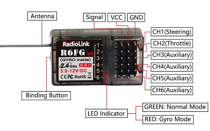
Receiver R6FG(Standard Pack)
Receiver packed with RC4GS V3 is R6FG, 2.4GHz 6 channels, gyro integrated and high voltage servo supported.
R6FG Specification
① Size: 35*20*13mm (1.38*0.79*0.51″)
② Weight: 6g (0.21 oz)
③ Channel: 6 channels
④ Antenna Length: 205mm(8.07″)
⑤ Operating Current: 30mA
⑥ Operating Voltage: 3-12V
Receiver Installation and Binding
Binding
1. Put the transmitter and the receiver close to each other (about 50 centimeters) and power both on.
2. Switch on the transmitter and the led on R6FG will start flashing slowly.
3. There is a black binding button(ID SET) on the side of receiver. Press the button for more than 1 second and release, the led will flash quickly, meaning binding process is ongoing.
4. When the led stops flashing and is always on, binding is complete and there will be a signal tower shown on top of the LCD screen of the transmitter. If not succeed, the led will keep flashing slowly to notify, repeat the above steps.
Note:
1. The binding between your R6FG and RC4GS V3 is already complete by default. Just need to make sure there is the solid light of R6FG and the signal tower in the transmitter.
2. NO gyro by default as factory setting. Since integrated gyro in R6FG will self-check, it is very important
to remain R6FG still when powering it on. There are two LED indicators on R6FG. GREEN indicates the normal working mode while RED indicates the gyro working mode. When RED is off means NO gyro. If binding is not successful, the green led will keep flashing to notify.
Note of Receiver Usage
- Keep antennas as straight as possible, or the effective control range will reduce.
- Big models may contain metal parts that influence signal emission. In this case, antennas should be positioned at both sides of the model to ensure the best signal status in all circumstances.
- Antennas should be kept away from metal conductor and carbon fiber at least half inch away and no over bending.
- Keep antennas away from motor, ESC or other possible interference sources.
- Sponge or foam material is advised to use to prevent vibration when installing receiver.
- Receiver contains some electronic components of high-precision. Be careful to avoid strong vibration and high temperature.
- Special vibration-proof material for R/C like foam or rubber cloth is used to pack to protect receiver. Keeping the receiver in a well sealed plastic bag can avoid humidity and dust, which would possibly make the receiver out of control.
When all the above steps are complete, please turn off the transmitter and re-power on to test if the receiver is correctly connected with it.
Working Mode
R6FG has two working modes:normal working mode and gyro working mode.
- Normal Working Mode
Green LED, gyro will NOT be working.
- Gyro Function Working Mode
Both GREEN and RED LED on.
Gyro Setup
The gyro function of receiver R6FG for professional car drifting can be enabled and disabled. When it’s enabled, the turning stability can be maximized during competition. When there is false position, gyro function keeps the car straight forward and turn precisely.
A. Gyro Enabled
Factory setting is gyro function OFF by default.
Short press the binding button (ID SET) three times with interval less than 1 second, the RED indicator flashes three times. Red LED on/off indicates the gyro function is on/off.
B. Gyro Phase
When the gyro forward is enabled, try to turn the model car to check if the gyro is correcting the wheels. Normally, the wheels should turn right to correct when the car is turned left while the wheels should turn left to correct when the car is turned right. If the gyro phase is reversed, short press the binding button (ID SET) twice with interval less than 1 second. The RED indicator flashes twice means the gyro phase is switched.
C. Gyro Sensitivity Adjustment
The gyro sensitivity can be adjusted in the BASIC MENU-- GYRO in the transmitter. VR and STD modes are optional. Gyro sensitivity setting is CH3 by default (factory setting) and can be adjusted by VR knob. If VR knob or channel 3 is used for other functions, select STD mode and adjust the gyro sensitivity by buttons Dec(-) or Inc(+) . Percentage is displayed when sensitivity is adjusted while the bigger percentage means higher sensitivity.
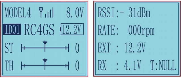
Signal/RSSI Real-time Return
Power on the transmitter and the receiver and complete the binding, signal will be displayed on the main interface of transmitter. Short press EXIT twice and enter the interface with returned information including RSSI value.
Warning can be set with a certain low RSSI value after testing by changing distance:
Press EXIT and ENTER simultaneously to enter MENU=>press Inc(+) to highlight “19. ALARM” =>Press ENTER to (dis)activate the warning and set the RSSI warning value.
Note: The ‘RATE: RPM’ and ‘T: NULL’ telemetry functions are still under development. If there are new developments, we will announce them to the RadioLink official website as soon as possible.
Telemetry of Model Battery and Receiver Voltage
When done binding with R7FG or R8F receiver, besides the telemetry of RSSI, receiver voltage, model battery voltage (maximum up to 8S lithium battery, 33.6V) can also be returned in real time. Users can personalize the warning value of low model battery voltage depending on the actual needs.
Press EXIT and ENTER simultaneously to enter MENU=>press Inc(+) to highlight “19. ALARM =>Press ENTER to set the model battery voltage warning value.
Normally we set the warning value with the single cell voltage as 3.7V. For example, if it is 3S lithium battery used in the model car, the warning value should be set as (3.7V*3S=)11.1V.
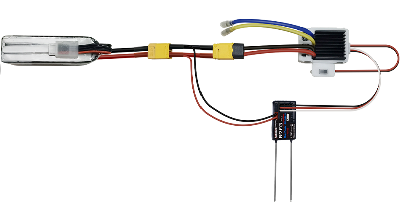
Model battery voltage return can be easily achieved by connecting the male end of the battery wire to ESC while the female end to the battery and the wire with a JST head connects TELEMETRY (+-) of R7FG/R8F as below picture shown. No extra module is needed.
Once connect with success, the returned model voltage will be displayed on the interface of returned flight information.
Note
- Battery connected to TELEMETRY port is only for 2S-8S battery voltage telemetry. The TELEMETRY port cannot be used to power the receiver.
- Make sure the polarity of the battery is not reversed. Otherwise reverse insertion will cause abnormal voltage display of telemetry.
RC4GS V3 Functions
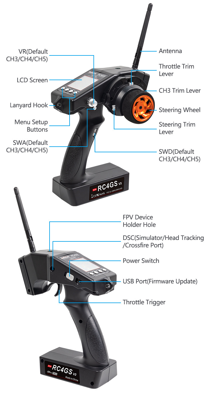
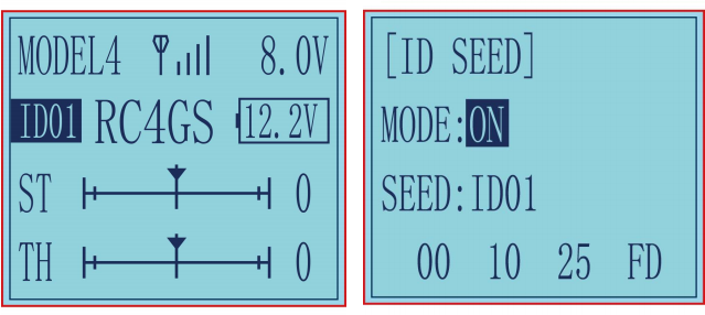
Display on LCD Screen
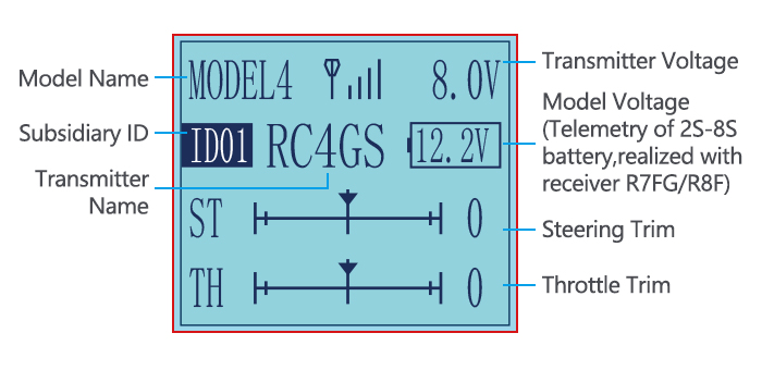
When the transmitter is powered on, LCD screen shows Model Name, Transmitter Name, Transmitter Voltage, Steering Trim, Throttle Trim, Model Voltage, Subsidiary Model ID, Returned Signal.
Note
- The Subsidiary ID won’t display until the function is activated in the menu ID SEED.
- The telemetry function of model battery voltage can only be realized with R7FG/R8F.
- When binding is done, there’s signal tower on top middle of the screen. As there’s no amplifier module added on R6FG, the signal telemetry from receiver is about 80m(262.5ft). If the distance is longer than 80m, the signal tower may disappear but the control range of RC4GS V3 is as long as 400m(1312ft).
Model Name
The system can store the data of 30 models in total. Model name will show on the LCD when you power on the transmitter. Please make sure the model name is the correct one that you want.
If the model name you chose is not corresponding with your model, the settings should be wrong.
Transmitter Voltage
In addition to the model, LCD can show the voltage of transmitter battery. Users can set transmitter low voltage alarm in the basic menu — ALARM. Low voltage alarm of the transmitter is 7.2V by factory default.It can be customized on 2-4S battery. When the voltage reaches the alarm value, there will be a text displayed on the transmitter screen and a «didi» sound dual alarm prompt to remind you.
Transmitter function menu setting
When you want to browse or change a setting of transmitter, you should go into function menu setting mode. Under function menu setting mode, you can set up Language «LANGUAGE» , Model Select «MODEL», End Point Adjust «EPA», Steering Exponential «STEXP», Steering Speed «STSPD», Throttle Exponential «THEXP», Throttle Speed «THSPD», A.B.S. Function «A.B.S», Throttle Acceleration «ACCEL», Idle-Up «IDLUP», Sub-trim «SUB-TRIM», Channel Reverse «REVERSE», Steering/Throttle Dual Rate «D/R», Brake Side Adjustment «ATL», Programmable Mixes «PMIX01/02», Auxiliary Channel 3, 4, and 5 «AUX-CH»,Model name «NAME»,
Low Voltage “ALARM”. Gyro Sensitivity”GYRO”, Fail Safe”F/S”, Subsidiary ID”ID SEED”, DSC port setting
«DSC», Timer setting «TIMER», Factory Reset «RESET».
As the factory default firmware version of RC4GS V3 is V6.6.7, below menu introduction is based on this firmware version. Menus maybe various if the firmware version is lower. The latest firmware can be downloaded from www.radiolink.com
Language “LANGUAGE”
Both English and Chinese version menu are available for which is convenient for Chinese and English-speaking players to personalize function menus.
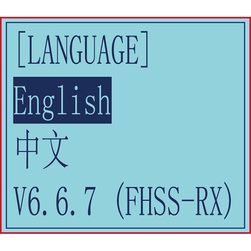
(1) Access the function menu (By pressing “Exit” and “Enter”buttons simultaneously and holding them down for one second), the Language select function will be chosen.
(2) Press “Enter” button to get into “LANGUAGE” function interface.
(3) Use“Dec(-)”or “Inc(+)”key to select “中文”or “English”, the selected language will be with black shading effect.
(4) Press “Enter” button, the desired language is selected, Numbers at the bottom means the current firmware version. Eg. V6.6.7 in above picture.
Model Select “MODEL”
RC4GS V3 can store model memories for 30 models. Use
this function to call a new model. Each model can independently set the parameters of each function.
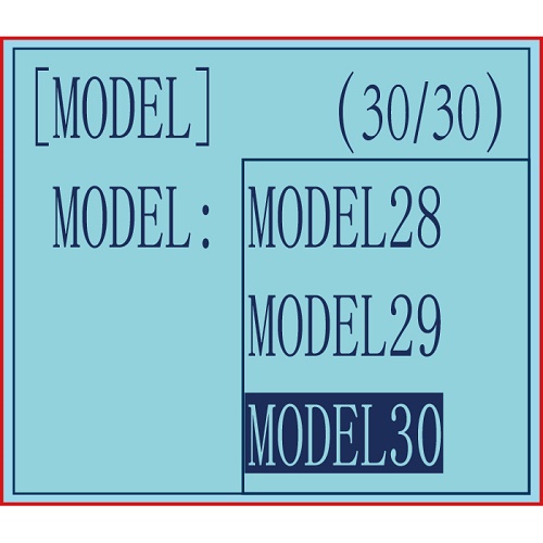
(1) Access the function menu (By pressing “Exit” and“Enter” buttons simultaneously and holding them down for one second), press “Enter” key once, the Model select function will be chosen.
(2) Press “Enter” button, the current active model will be blinking.
(3) To activate a different model by pressing “Dec(-)” or “Inc(+)” button until the desired model blinks.
(4) Press “Enter” button, the selected model stops blinking, now the model has been selected.
(5) Return to the initial screen by pressing “Exit” button twice.
End Point Adjust “EPA”
Use EPA when performing left and right steering angle adjustments, throttle high side/brake side operation amount adjustment, and channel 3 servo up side/down side operation amount adjustment during linkage.
Correct the maximum steering angle and left and right steering angles when there is a difference in the turning radius due to the characteristics, etc. of the vehicle.
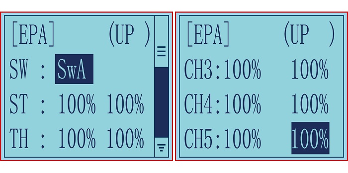
Setting item (channel and direction)
Steering EPA Throttle EPA
ST:0%~120%(left/ right) TH:0%~120%(forward/brake)
Initial value:100% Initial value : 100%
Aux Servo EPA Aux Servo EPA
CH3:0%~120%(left/ right) CH4:0%~120%(left/ right)
Initial value: 100% Initial value: 100%
Aux Servo EPA
CH5:0%~120%(left/ right)
Initial value: 100%
End point adjustment
(1) Long press "Exit" and "Enter" button simultaneously for one second to enter the function menu of RC4GS V3. Press "Inc(+)" button at the bottom of the screen to move the cursor to "3. EPA", and then press " Enter” button to enter the function setting interface.
(2) Switch setting: Set a switch or button to switch in different end points.
A. You can set SWA, SWD, or the lock modes of these two switch buttons LK-A, LK-D.
B. "NULL" means no switch assigned. After setting the end point parameter of the corresponding channel, the transmitter will always execute the set end point by default.
C. UP (up)/DOWN (down: It indicates the position of the selected switch. Push/Press the switch to different positions to set different end points.
D. Setting method: Press "Dec(-)" or "Inc(+)" button at the bottom of the screen to move the cursor to "NULL" next to the switch, then press "Enter" button, the corresponding setting starts to flash, then press "Dec(-)" or "Inc(+)" button to select the switch or button to be set, and press "Enter" button to confirm the option after the selection. The switch setting stops flashing and the switch setting is complete.
(3) Set the end point of each channel: press “Dec(-)” or “Inc(+)” button to move the cursor to the rate next to the channel, and then press the “Enter” button, the corresponding value starts to flash , and then press “Dec(-)” or “Inc(+)” button to adjust the rate value. After setting, press "Enter" key, the rate value stops flashing, and the channel rate value is set.
(4) Press "Exit" to return to the home page.
Steering Exponential “STEXP”
This function is used to change the sensitivity of the steering servo around the neutral and both ends position. It has no effect on the maximum servo travel.
Adjust the sensitivity of direction wheel both in neutral position and ends.
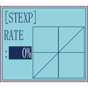
Setup Item
RATE: Steering EXP rate
Adjustment range
-100%~0%~+100%
Initial value: 0%
0%~-100%: Sensitivity around neutral position is low, getting higher when approaching ends.
0%: Sensitivity around the neutral and ends position is equal
0%~+100%: Sensitivity around neutral position is high, getting lower when approaching ends
Steering operation curve adjustment
(1) Access the function menu (By pressing “Exit” and “Enter ”buttons simultaneously and holding them down for one second ), press “Inc(+)” button three times to chose EAP function.
(2) Press “Enter” button to get into STEXP function interface, press “Enter”key and the initial value of the rate will blink, then you can press “Dec(-) ”or “Inc(+)”button to adjust the value and the curve of the rate shown in the figure will change correspondingly.
(Note: In the interface of adjusting the value, return to the initial value «0%» by pressing “Dec(-)” and“Inc(+)” buttons simultaneously for about 1 second.)
(3) Press “Enter” button, the adjusted value of the rate stops blinking, now the value of the rate has been set.
(4) Return to the initial screen by pressing“Exit” button twice.
Note: the Vertical cursor shown in the figure moves in step with steering wheel operation.
Steering Speed “STSPD”
Quick steering operation will cause momentary under steering, loss of speed, or spinning. This function is effective in such cases.
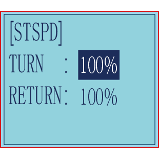
Setup item
TURN: turn direction
RETURN: return back to the original direction
Adjustment range
0%~100% (each direction)
At 100%, there is no delay
Steering servo delay
(1) Access the function menu (By pressing “Exit” and “Enter” buttons simultaneously and holding them down for one second), press “Inc(+)” button four times to chose STSPD function.
(2) Press“Enter” button to get into STSPD function interface, press “Dec(-)” or“Inc(+)” button to select setup item, then press “Enter” key and the initial value of selected setup item will blink.
(3) Use“Dec(-)” or “Inc(+)” button to adjust the value of the selected setup item.
(Note : In the interface of adjusting the value, return to the initial value «100%» by pressing“Dec(-)” and“Inc(+)” buttons simultaneously for about 1 second.)
(4) Press “Enter”button, the adjusted value of the selected setup item stops blinking, now the value of the selected setup item has been set.
(5) Return to the initial screen by pressing “Exit” button twice.
Throttle Exponential “THEXP”
This function makes the throttle high side and brake side direction servo operation quicker or milder. It has no effect on the servo maximum operation amount. For the high side, selection from among three kinds of curves (CRV/VTR/EXP) is also possible.
The curve can be divided into: Five dots throttle curve adjustment, Single point adjustment, Exponential curve adjustment, Braking index curve adjustment. To elevation point, we can select(Exponential curve/Single point curve/Five points curve).
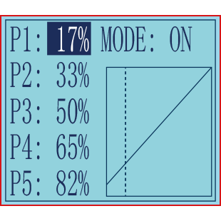
Curve point adjustment(select five points 1-5)
(1) Press»Enter» button,The curve point value start flashing,then press»Dec(-)»and»Inc(+)» button to adjust the starting value.
(2) Press «Enter» button ,starting value stop flashing,adjustment is completed.
(3) Press «Exit» button for two times,back to the initial interface.
Throttle curve adjustment
Adjustment method for CRV curve
Setup Items
Mode: ON/OFF
RATE: 0%~100%
- Enter the function menu and use“ Dec(-) ” or “ Inc(+) ”button
to access THEXP function. Select “FWD-CRV” function.
- Press “Dec(-)” or “Inc(+)” button to select curve points 1~5
for curve point adjustment that you want, from the graph you will clearly see the changes you have made.
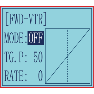
Adjustment method for VTR curve
Adjustment range
TG.P: 20-80
RATE: -100~0~+100
- Enter the function menu and use “Dec(-)” or“Inc(+)”button
to access THEXP function. Select“FWD-VTR” function.
- Press “Dec(-)” or “Inc(+)” button to select RATE for forward side adjustment that you want, when the “MODE” value is “OFF” the VTR will not work, only the “MODE” value set to “ON” the VTR function is available. From the graph you will clearly see the changes you have made on TG.P and RATE.
Adjustment method for EXP curve
Setup items
MODE: EXP turn on or turn off
RATE: EXP rate
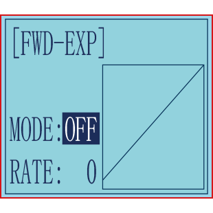
Adjustment range
MODEL: OFF/ON
RATE: -100 ~ 0 ~ +100
- Enter the function menu and use “Dec(-)” or “Inc(+)” button
to access THEXP function, then select the “FWD-EXP” function.
- Press “Dec(-)” or “Inc(+)” button to select RATE for adjustment, set the most comfortable value you want. From the graph you will clearly see the changes you have made on the EXP RATE, also move the trigger to check the throttle status.
Adjustment method for BRK-EXP curve
Setup Items
RATE: BRK-EXP rate
Adjustment range
RATE: -100 ~ 0 ~ +100
0~-100: flat braking
0: uniform braking
0~+100: sensitive braking
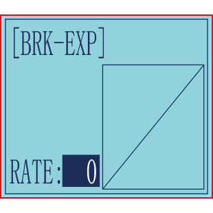
Brake side adjustment (select BRK)
- Press “Enter” key, the current BRK value will blink, use “Inc(+)” button to adjust the + side when you want to quicker the rise and use“Dec(-)” button to adjust the — side when you want to make the rise milder.
(Note: In the interface of adjusting the value, return to the initial value «0» by pressing “Dec(-)” and “Inc(+)” buttons simultaneously for about 1 second.)
- Press “Enter” button, the adjusted BRK value stops blinking, now the BRK value has been set.
- When ending setting, return to the initial screen by pressing “Exit” button twice.
Throttle Speed “THSPD”
Throttle servo delay
Sudden trigger operation on a slippery road only causes the wheels to spin and the vehicle cannot accelerate smoothly. Setting the throttle speed function reduces wasteful battery consumption while at the same time permitting smooth, enjoyable operation.
Operation
Throttle servo(amp) operation is delayed so that the drive wheels will not spin even if the throttle trigger is operated more than necessary. This delay function is not performed when the throttle trigger is returned and at brake operation.
OFF: Speed1 or speed2 can be selected.
OFF means shut down the throttle speed function
Adjustment method for SPEED1
Setup items
MODE: Speed type selection
ALL: Speed adjustment
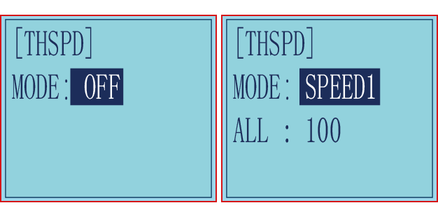
Adjustment range
0~100 (each direction)
At 100, there is no delay
(1) Enter the function menu and use “Dec(-)”or“Inc(+) ” button to access THSPD function.
(2) Press “Enter” button to get into THSPD function interface.
(3) If initial MODE setup item is SPEED1, {if initial MODE setup item is SPEED2 or OFF, you need to select SPEED1 by pressing“Dec(-)” or “Inc(+)”button to select MODE setup item , then press “Enter” key, SPEED2 or OFF will blink, press “Dec(-)” or “Inc(+)” button, when the blinking SPEED 2 or OFF change to blinking SPEED 1, press “Enter” key, SPEED1 will stop blink, now SPEED1 is selected}, press “Dec(-)” or “Inc(+)” button to select ALL setup item, then press“Enter” key, the initial value will blink, use“Dec(-)”or“Inc(+)” button to adjust the delay of the entire throttle forward side range.
(Note: In the interface of adjusting the value, return to the initial value «100» by pressing “Dec(-)” and “Inc(+)” buttons simultaneously for about 1 second.)
Press “Enter” button, the adjusted value stops blinking, now the value has been set.
(4) When ending setting, return to the initial screen by pressing “Exit” button twice.
Adjustment method for SPEED2
Setup items
MODE: Speed type selection
LOW: Low side range speed adjustment
HIGH: High side range speed adjustment
TGP1: Low and medium speed switching point

Adjustment range
LOW: 0~100
HIGH: 0~100
At 100, there is no delay
TGP1: 0~100
(1) Enter the function menu and use “Dec(-)”or “Inc(+) ” button to access THSPD function.
(2) Press “Enter” button to get into THSPD function interface.
(3) If initial MODE setup item is SPEED 2, {if initial MODE setup item is SPEED 1, you need to select SPEED2 by pressing “Dec(-)” or “Inc(+)” button to select MODE setup item, then press “Enter” key, SPEED1 or OFF will blink, press “Dec(-)” or “Inc(+)” button, when the blinking SPEED1 or OFF change to blinking SPEED2, press “Enter” key, SPEED2 will stop blinking, now SPEED2 is selected}, press “Dec(-)” or “Inc(+)” button to select «LOW» or «HIGH» delay adjustment or“TGP1” speed switching point adjustment.
(4) Press “Enter” key to confirm «LOW» or «HIGH» or “TGP1” setup item, and the value of your selected setup item will blink. Use “Dec(-)” or “Inc(+)” button to adjust the value.
(Note: In the interface of adjusting the value, return to the initial value (the initial value of LOW and HIGH is “100”, the initial value of TGP1 is “30”) by pressing “Dec(-)” and “Inc(+)” buttons simultaneously for about 1 second.)
Press “Enter” button, the adjusted value stops blinking, now your selected value has been set.
(5) When ending setting, return to the initial screen by pressing “Exit” button twice.
A.B.S. Function “A.B.S”
Pulse brake
When the brakes are applied while cornering with a 4 Wheel Drive or other type of vehicle, under-steer may occur. The generation of under-steer can be eliminated and corners can be smoothly cleared by using this function.
Operation
— When the brakes are applied, the throttle servo will pulse intermittently. This will have the same effect as pumping the brakes in a full size car.
— The brake return amount, pulse cycle, and brake duty can be adjusted.
— The region over which the ABS is effective can be set ac-cording to the steering operation. (Mixing function)
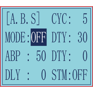
Setup items
ABP: Brake return amount
DLY: Delay amount
CYC: Cycle speed
TGP: Operation point
DTY: Cycle duty ratio
STM: Steering mixing
-ABP(Amount of brake return): Sets the rate at which the servo returns versus trigger operation for brake release. When set to 0, the ABS function is not
Performed. When set to 50, the servo returns 50% (1/2)of the trigger operation amount and when set to 100, the servo returns to the neutral position.
-DLY(Delay): Sets the delay from brake operation to ABS operation. When set to 0, the ABS function is
activated without any delay. At 50%, the ABS function is activated after a delay of approximately 0.7 second and at 100, the ABS function is activated after a delay of approximately 1.4 seconds.
-CYC(Pulse speed): Sets the pulse speed (cycle). The smaller the set value, the faster the pulse cycle.
— TGP(Trigger point): Sets the trigger point at which the ABS function begins to operate at brake operation.
-DTY(Cycle duty ratio): Sets the proportion of the time the brakes are applied and the time the brakes are released by pulse operation. The ratio can be set to +3 ~ 0~-3 in 7steps.
— STM(Steering mixing): Sets ABS operation ON/OFF according to the steering operation range.
A.B.S function adjustment
Enter the function menu and use “Dec(-)” or “Inc(+)” button to access A.B.S function, then press“Enter” button to get into A.B.S function interface.
(1) Brake return amount adjustment
Select the setting item «ABP» by pressing “Dec(-)” or “Inc(+)” button, then press “Enter” key and the initial value of “ABP” will blink. Use “Dec(-)”or“Inc(+)”button to adjust the return amount.
(Note: In the interface of adjusting the value, return to the initial value «50» by pressing “Dec(-)” and “Inc(+)” buttons simultaneously for about 1 second.)
Press “Enter” button, the adjusted value stops blinking, now the value has been set.
«0»: No return
«50»: Return to the 50% position of the brake operation amount
«100»: Return to the neutral position.
Brake return amount (ABP)
0 ~ 50 ~ 100
Initial value: 50
— Brake return amount (ABP) is influenced by the «EXP» rate on the brake side.
(2) Delay amount setup
Select the setting item «DLY» by pressing “Dec(-)” or “Inc(+)” button, then press “Enter” key and the initial value of “DLY” will blink. Use “Dec(-)”or “Inc(+)”button to adjust the delay amount.
(Note: In the interface of adjusting the value, return to the initial value «0» by pressing “Dec(-)” and “Inc(+)” buttons simultaneously for about 1 second.)
Press “Enter” button, the adjusted value stops blinking, now the value has been set.
«0»: A.B.S. function performed without any delay
«50»: A.B.S function performed after an approximate 0.7 sec delay
«100»: A.B.S. function performed after an approximate 1.7 secs delay
Delay amount (DLY)
0 ~ 100
Initial value; 0
(3) Pulse speed adjustment
Select setting item «CYC» by pressing “Dec(-)” or “Inc(+)” button, then press “Enter” key and the initial value of “CYC” will blink. Use “Dec(-)” or “Inc(+)”button to adjust the pulse speed (cycle).
(Note: In the interface of adjusting the value, return to the initial value «5» by pressing“Dec(-)” and “Inc(+)” buttons simultaneously for about 1 second.)
Press “Enter” button, the adjusted value stops blinking, now the value has been set.
— The smaller the set value, the faster the pulse speed.
Cycle speed (CYC)
0 ~ 30
Initial value: 5
(4) Operation point setup
Select setting item «TGP» by pressing “Dec(-)” or “Inc(+)” button, then press “Enter” key and the initial value of “TGP” will blink. Use “Dec(-)” or “Inc(+)”button to adjust the operation point.
(Note: In the interface of adjusting the value, return to the initial value «30» by pressing “Dec(-)” and “Inc(+)” buttons simultaneously for about 1 second.)
Press “Enter” button, the adjusted value stops blinking, now the value has been set.
— Sets the throttle trigger position at which the A.B.S. function is performed. The number is the 100 display with the full brake position made 100%.
Operation point (TGP)
0 ~ 100
Initial value: 30
(5) Cycle duty ratio setup
Select setting item «DTY» by pressing “Dec(-)” or “Inc(+)” button, then press“Enter” key and the initial value of “DTY” will blink. Use “Dec(-)” or “Inc(+)”button to adjust the duty ratio.
(Note: In the interface of adjusting the value, return to the initial value «0» by pressing “Dec(-)” and “Inc(+)” buttons simultaneously for about 1 second.)
Press “Enter” button, the adjusted value stops blinking, now the value has been set.
«-3»: Brake application time becomes shortest. (Brakes lock with difficulty)
«+3»: Brake application time becomes longest (Brakes lock easily)
(Remark) For low grip set at the — side and for high grip set at the + side.
Duty ratio (DTY)
-3 ~ 0 ~ +3
Initial value: 0
(6) Steering mixing setup
Select setting item «STM» by pressing“Dec(-)”or“Inc(+)”button, then press“Enter” key and the initial value of “STM”will blink. Use “Dec(-)”or “Inc(+)”button to adjust the steering mixing range.
(Note: In the interface of adjusting the value, return to the initial value «OFF» by pressing “Dec(-)” and “Inc(+)” buttons simultaneously for about 1 second.)
Press“Enter”button, the adjusted value stops blinking, now the value has been set.
-Sets the range within which the A.B.S. function is performed relative to steering wheel operation.
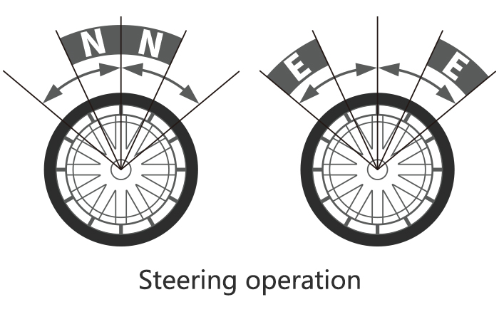
Steering mixing (STM)
OFF, N10 ~ N100, E10 ~ E100
Initial value: OFF
When steering mixing is set and steering operation enters the set range, «*» is displayed in front of the number. When mixing is OFF, the A.B.S function can operate over the entire steering range.
When ending setting, return to the initial screen by pressing “Exit” button twice.
Throttle Acceleration “ACCEL”
Function which adjusts the movement characteristic from the throttle neutral position.
The servo will jump to the input position at its maximum possible speed. Unlike exponential, which adjusts the whole throttle movement into a curve, throttle acceleration simply «jumps» away from neutral and then leaves the remaining response linear.
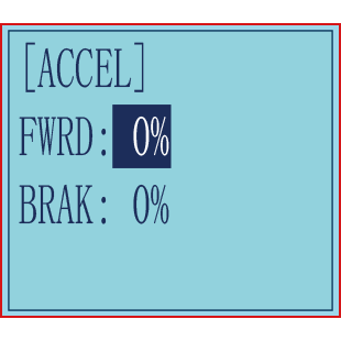
Setup item
FWRD: Forward side acceleration amount
BRAK: Brake side acceleration amount
Throttle acceleration adjustment
Enter the function menu and use “Dec(-)” or “Inc(+)” button to access ACCEL function, then press “Enter” button to get into ACCEL function interface.
- Forward acceleration amount adjustment
Press “Dec(-)” or “Inc(+)” button to select “FWRD”, press“Enter”key to confirm and the initial value of “FWRD” will blink, then use “Dec(-)”or“Inc(+)” button adjust the acceleration amount.
(Note: In the interface of adjusting the value, return to the initial value «0%» by pressing “Dec(-)” and “Inc(+)” buttons simultaneously for about 1 second.)
Press“Enter”button, the adjusted value stops blinking, now the value has been set.
«0%»: No acceleration
«100%»: Maximum acceleration(Approximately1/2of the forward side steering angle)
Forward acceleration amount(FWRD)
0%~100%
Initial value: 0%
(2) Brake side acceleration amount adjustment
Press “Dec(-)” or “Inc(+)” button to select “ BRAK ”, press“Enter”key to confirm and the initial value of “BRAK” will blink, then use“Dec(-)”or“Inc(+)”button adjust the acceleration amount.
(Note: In the interface of adjusting the value, return to the initial value»0%» by pressing
“Dec(-)” and “Inc(+)” buttons simultaneously for about 1 second.)
Press “Enter” button, the adjusted value stops blinking, now the value has been set.
«0%»: No acceleration
«100%»: Maximum acceleration (Brake side maximum steering angle)
Brake side acceleration amount(BRAK)
0%~100%
Initial value: 0%
When ending setting, return to the initial screen by pressing “Exit” button twice.
Idle-Up “IDLUP”
Idle up at engine start
Use this function to improve the starting characteristics of the engine by raising the idling speed when starting the engine of a gas powered car.
Idle-Up rate (RATE)
-50% ~ -1%, 0%, +1% ~ +50%
Initial value: 0%
«-«: Brake side
«+»: Forward side
Idle-Up «IDLUP»
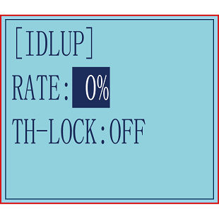
(1) Enter the function menu and use “Dec(-)” or“Inc(+) ” button to access IDLUP function.
(2) Press “Enter” button to get into IDLUP function interface.
(3) Press “Enter” key, and the initial value of RATE will blink. Use“ Dec(-) ” or “Inc(+)” button to adjust the value.
(Note: In the interface of adjusting the value, return to the initial value «0%» by pressing “Dec(-)” and “Inc(+)” buttons simultaneously for about 1 second.)
Press “Enter”button, the adjusted value stops blinking, now the value has been set.
(4) When ending setting, return to the initial screen by pressing “Exit”button twice.
Throttle Lock “TH-LOCK”
In addition to adjusting the throttle speed when the throttle trigger is in the neutral position, the Idle up at engine start function can also set the throttle lock, select the throttle value that needs to be locked, and the setting range is -100% to +100%. After the throttle is locked, no matter the current No matter where the throttle trigger is, the throttle output will jump to the set value.
This function is controlled by the trigger of the SWA jog switch, press to lock, press again to unlock, the control switch defaults to SWA and cannot be modified.
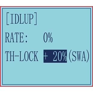
The specific setting method is as follows:
- Enter the function menu and use the «Dec(-)» or «Inc(+)» key to select the «TH-LOCK» setting item.
- Press the «Enter» button to enter the «TH-LOCK» function interface.
- Move the cursor to «Throttle Lock», press the «Enter» key again, «Throttle Lock» will start to flash, and then use the «Dec(-)» or «Inc(+)» key to adjust the amount of throttle lock.
- Press the «Enter» key, the adjusted value stops flashing, and the setting is complete.
- After setting, press the «Exit» key to return to the initial interface, and press the SWA switch to switch between locking and unlocking the throttle.
https://www.youtube.com/watch?v=vCEHpUoTLzE
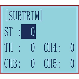
Sub-trim “SUB-TRIM”
Servo center position adjustment
Use this function to adjust the neutral position of the steering, throttle and all other channel.
Channel
ST: Steering(CH1)
TH: Throttle(CH2)
CH3: Channel3(VR)
CH4: Channel4(SWA)
CH5: Channel5(SWD)
Sub-trim
ST: -100~0~+100
TH: -100~0~+100
CH3: -100~0~+100
CH4: -100~0~+100
CH5: -100~0~+100
Initial value : 0
(1) Enter the function menu and use “Dec(-)”or “Inc(+)” button to access SUBTRIM function.
(2) Press “Enter” button to get into SUBTRIM function interface.
(3) Use “Dec(-)” or “Inc(+)” button to select ST channel, press “Enter”key, and the initial value of ST will blink. Use “Dec(-)” or “Inc(+)” button to adjust the center.
(Note: In the interface of adjusting the value, return to the initial value «0» by pressing “Dec(-)” and “Inc(+)” buttons simultaneously for about 1 second.)
(4) Press “Enter” key, the adjusted value stops blinking, now the center of ST has been adjusted.
(5) TH channel and CH3 can be set similarly.
(6) When ending setting, return to the initial screen by pressing “Exit” button twice.
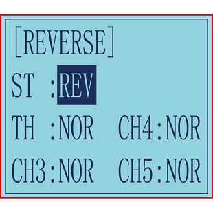
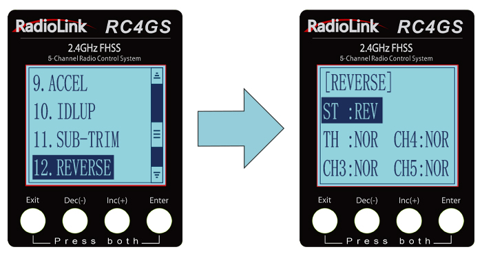
Channel Reverse “REVERSE”
Servo operation reversing
This function reverses the direction of operation of the servos related to transmitter steering, throttle, channel 3, channel 4, and channel 5 operation.
Channel
ST: Steering(CH1)
TH: Throttle(CH2)
CH3:Channel3(VR)
CH4: Channel4(SWA)
CH5: Channel5(SWD)
(1) Enter the function menu and use “Dec(-)” or“Inc(+)” button to access REV function.
(2) Press “Enter” button to get into REV function interface.
(3) Use “Dec(-)” or “Inc(+)” button to select ST channel, press “Enter”key, and the “NOR” will blink.
(4) Press “Enter” key, the “NOR” stops blinking, Use “Dec(-)”or“Inc(+)”button to reverse the ST servo operation direction.
(5) TH channel, CH3, CH4,and CH5.
(6) When ending setting, return to the initial screen by pressing “Exit” button twice.
Steering/Throttle Dual Rate “D/R”
Dual rate
The steering left and right servo travels are adjusted simultaneously. When you want to increase the servo travel, adjust the + side. When you want to decrease the servo travel, adjust the — side.
The servo travel amount of all channels can be reduced by Dual Rate setting. Dual rate function is different from EPA, which requires the travel amount on both sides of the channel to be set separately. Setting the rate of D/R will affect the left and right travel amount at the same time. For example, after setting a smaller throttle value, the travel amount of the model forward and brake will be reduced at the same time, the setting range is 0-100, the default is 100.
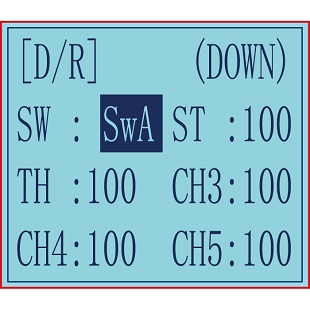
Dual Rate Setting:
(1) Long press "Exit" and "Enter" button simultaneously for one second to enter the function menu of RC4GS V3. Press "Inc(+)" button at the bottom of the screen to move the cursor to "13. D/R", and then press " Enter” button to enter the function setting interface.
(2) Switch setting: Set a switch or button to switch in different travel amount of each channel.
A. You can set SWA, SWD, or the lock modes of these two switch buttons LK-A, LK-D.
B. "NULL" means no switch assigned. After setting the travel amount of the corresponding channel, the transmitter will always execute the set value by default.
C. UP (up)/DOWN (down): It indicates the position of the selected switch. Push/Press the switch to different positions to set different travel amount.
D. Setting method: Press "Dec(-)" or "Inc(+)" button at the bottom of the screen to move the cursor to "NULL" next to the switch, then press "Enter" button, the corresponding setting starts to flash, then press "Dec(-)" or "Inc(+)" button to select the switch or button to be set, and press "Enter" button to confirm the option after the selection. The switch setting stops flashing and the switch setting is complete.
(3) Set the travel amount of each channel: press “Dec(-)” or “Inc(+)” button to move the cursor to the rate next to the channel, and then press the “Enter” button, the corresponding value starts to flash , and then press “Dec(-)” or “Inc(+)” button to adjust the rate value. After setting, press "Enter" button, the rate value stops flashing, and the channel rate value is set.
(4) Press "Exit" to return to the home page.
Example:
1. If you set SWA or SWD switch. Press it to one dual rate value, and release it to another dual rate value.
2. LK-A, LK-D are corresponding to the lock mode of SWA, SWD switches. Press it to one dual rate value, and press it again to another dual rate value.
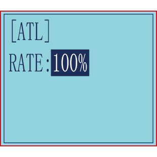
Brake Side Adjustment “ATL”
Brake side adjustment
This function decreases the set value when the braking effect is strong and increases the set value when the braking effect is weak.
Setup Item
RATE: Brake amount
Brake amount (RATE)
0%~100%
Initial value: 100%
(1) Enter the function menu and use “Dec(-)” or “Inc(+)”button to access ATL function.
(2) Press “Enter” button to get into ATL function interface.
(3) Press “Enter” key, and the initial value of RATE will blink. Use “Dec(-)”or“Inc(+)” button to adjust the value.
(Note: In the interface of adjusting the value, return to the initial value «100%» by pressing “Dec(-)” and “Inc(+)” buttons simultaneously for about 1 second.)
Press “Enter” button, the adjusted value stops blinking, now the value has been set.
(4) When ending setting, return to the initial screen by pressing“Exit” button twice.
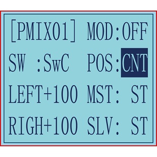
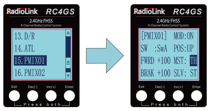
Programmable Mixes “PMIX01/02”
Programmable mixes between arbitrary channels
These functions allow you to apply mixing between the steering, throttle, CH3, CH4 and CH5. PMIX01 setting is the same with PMIX02
PMIX 01
Programmable Mixes «PMIX»
MXMD:Mix mode
Enter the function menu and use“Dec(-)”or “Inc(+)” button to access PMIX function, then press “Enter” button to get into PMIX function interface.
MOD: Mixing mode.
INH: means the mixing function is disabled. Regardless of whether there is a set control switch or value under this function, it is not enabled.
ON/OFF: means turning the function on and off. Set the mode to ON, the current mixing control can take effect.
SW: Switch to control the mix function. You can set SWA, SWD, or the lock modes of these four switch buttons LK-A, LK-D. «NULL» means no switch assigned. After setting the travel amount of the corresponding channel, the transmitter will always execute the set value by default.
POS: means the position of the switch used to control this function. UP (up)/DOWN (down): It indicates the position of the selected switch. Push/Press the switch to different positions to set different travel amount.
LEFT: Mixing rate (Left side)
RIGN: Mixing rate (Right side)
MST: Master channel
SLV: Slave channel
(1) Master channel
Channel selection (MST)
ST, TH, CH3, CH4, CH5
Initial value: ST
Select setup item»MST» by pressing “Dec(-)” or“Inc(+)”button, press“ Enter ” button, the initial master channel will blink. Use“ Dec(-)”or“ Inc(+) ” button to select the master channel you wish to adjust, press“Enter” button,the blinking master channel you selected will stop blinking.
(2) Slave channel
Channel selection (SLV)
ST, TH, CH3, CH4, CH5
Initial value: ST
Select setup item «SLV» by pressing “Dec(-)” or “Inc(+)” button, press “Enter” button, the initial slave channel will blink. Use “Dec(-)” or “Inc(+)”button to select the slave channel you wish to adjust, press “Enter” button, the blinking slave channel you selected will stop blinking.
(3) Left, forward or up side mixing amount adjustment
Mixing amount
-100~0~+100
Select the setting item «LEFT», «FWRD», or «UP»(These setup items are different depend on the master channel. ST: «LEFT»; TH: «FWRD»; CH3:»UP») by pressing “Dec(-)” or “Inc(+)” button. Press “Enter” key, the initial value of «LEFT», «FWRD», or «UP» will blink, Use “Dec(-)” or “Inc(+)” button to adjust the left, forward, or up side mixing amount.
(Note: In the interface of adjusting the value, return to the initial value «0» by pressing“Dec(-)” and “Inc(+)” buttons simultaneously for about 1 second.)
Press “Enter” key, the adjusted value stops blinking, the selected mixing amount has been adjusted.
(4) Right, brake or down side mixing amount adjustment
Mixing amount
-100~0~+100
Select the setting item «RGHT», «BRAK», or «DOWN»(These setup items are different depend on the master channel.ST:»RGHT»; TH:»BRAK»;CH3:»DOWN») by pressing “Dec(-)” or “Inc(+)” button. Press“Enter”key,the initial value of «RGHT», «BRAK», or «DOWN» will blink, Use“Dec(-)”or“Inc(+)”button to adjust the right, brake, or down side mixing amount.
(Note: In the interface of adjusting the value, return to the initial value «0» by pressing “Dec(-)” and “Inc(+)” buttons simultaneously for about 1 second.)
Press “Enter” key, the adjusted value stops blinking, the selected mixing amount has been adjusted.
(5) Mixing mode setup
Mixing mode (MXMD)
OFF, MIX
Initial value: OFF
Select setup item»MXMD»by pressing“Dec(-)”or “Inc(+)” button, press “Enter “ button, the initial mixing mode“OFF”will blink. Press“Dec(-)”or “Inc(+)”button to switch “OFF” to “MIX”, press “Enter” button, the blinking “MIX” will stop blinking.
«OFF»: Mixing proportional to master channel operation.
«MIX»: Mixing by master channel another function considered.
(5) When ending setting, return to the initial screen by pressing “Exit” button twice.
PMIX02
PMIX02 setting is the same as the PMIX01.
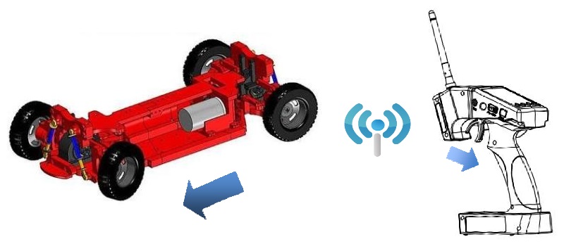
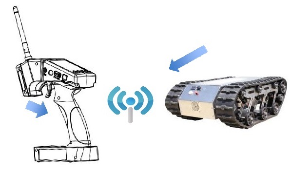
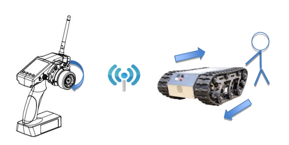
Take a dual-engine model (eg. Tracked vehicle) as an setting example.
Working theory of tracked vehicles
- RC Cars: One execute unite of radio controls a movement of a car (eg. Steering wheel to Ch1-Direction to turn left/right). Every R/C channel operation and every execute unite of car is ONE TO ONE.
When pulling the trigger, the car moves forward.
- Dual-engine Models: Being dual-engine category, tracked vehicle has two motors and each track is driven by each motor.
- Mix Control: The throttle (a function) on R/C monitors two motors(two execute unites) move
forward/backward simultaneously. That is, ONE TO TWO mix control. On the other hand, the turning of steering wheel makes one motor forward while the other backward at the same time to achieve direction turning. Same as ONE TO TWO mix control.
- Dual Mix Control: As controlling dual-engine vehicles drive forward/backward and turn left/right, two mix controls at the same time are needed. RADIOLINK RC4GS has two programmable mix controls.
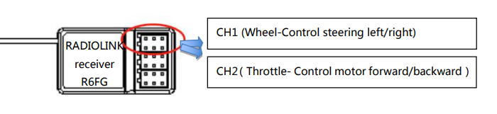
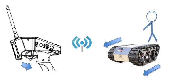
Reverse Setup before Mix Control Setup
Before setting the mix controls, please check if the reverses working correctly by testing its wheel and throttle. Take steering wheel— left track (Ch1 on receiver) and throttle—right track(Ch2 one receiver) as example.
1. Throttle Reverse:NOR-REV
Hold RC4GS V3 as the below pic. Normally, pull the throttle, the right track should be moving forward while push the throttle and the right track should be backward.
Pull the throttle,right track moves forward,left track remains still
If pulling the throttle and the left track moves backward; Or pushing the throttle and the left track moves forward, meaning the initial throttle is reversed and needs to be set. Please refer to the “button operation”and get into below interface to complete the setup.
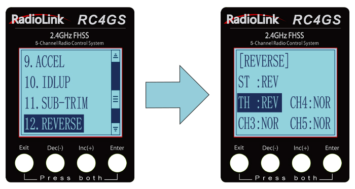
* If the throttle reverse is correct, skip this throttle reverse setup.
2. Steering Reverse:NOR/REV
Hold RC4GS V3 as the below pic. Normally, if turn the wheel right/clockwise, the left track should be moving forward while turn the wheel left/anticlockwise and the left track should be backward.
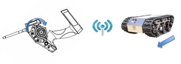
Turn the wheel clockwise, the left track moves forward,the right track remains still
If turning the wheel right and the right track moves backward; Or turning the wheel left and the right track moves forward, meaning the initial steering is reversed and needs to be set. Please refer to the “button operation”and get into below interface to complete the setup.
* If the steering reverse is correct, skip this steering reverse setup.
After setting the throttle/ steering reverse, then mix control can be set.
Mix Control Setup
- Throttle mix steering:Tracked vehicles moving forward/backward
As tracked vehicles moving forward/backward is controlled by throttle, throttle leads steering in the mix control. That is, Master-Throttle, Slave-Steering. Please refer to the “button operation”and get into below interface to complete the setup.
* Percentage value varies the speed;
”+”means Master and Slave move to same direction at the same time
Throttle mix steering setup completed, both tracks moves forward when pulling the throttle
- Steering mix Throttle:Tracked vehicles turning left/right
As tracked vehicles turning left/right is controlled by steering, steering leads throttle in the mix control. That is, Master-Steering, Slave-Throttle. Please refer to the “button operation”and get into below interface to complete the setup.
* Percentage value varies the turning angle;
”-”means Master and Slave move to different directions at the same time
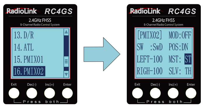
Steering mix throttle setup completed, left track moves forward while right backward when turning the wheel clockwise. The differential realizes the right turning of track vehicle
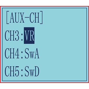
Auxiliary Channel “AUX-CH”
In addition to the two basic channels of the steering channel (channel 1) and the throttle channel (channel 2), RC4GS V3 also has three auxiliary channels, all of which can be customized to assign control switches.
The control switch of the auxiliary channel can be selected as ST, TH, VR, SwA, SwD, LK-A, LK-D, NULL.
When it is set to NULL, the channel will not be controlled by any switch,
When the channel is set to ST as the control switch, the channel will be controlled by the steering wheel;
When the channel is set as TH as the control switch, the channel will be controlled by the throttle trigger;
SwA and SwD are jog switches. When SwA/SwD is pressed, the channel output value will jump from the initial
value to the maximum value (or minimum value), and when the switch is released, it will return to the initial value (For example, after pressing SwA, the channel output +100 , and after releasing SwA, the channel output will return to -100);
LK-A is the lock mode of SwA. When the channel is set to LK-A as the control switch,after pressing SwA, the output of the channel will jump to the maximum value (or minimum value), and will not return to the initial value when the switch is released. (For example, after pressing SwA, the channel outputs +100, and after releasing the switch, the +100 will remain unchanged. After pressing SwA again, the channel will output -100 , and the rudder will remain unchanged after releasing it). LK-D is the lock mode of SwD.
Note: The lock mode is another working logic of the jog switch and the three-way switch. After the channel control switch is set to LK-A or LK-D, the SwA or SwD switch is also used to control the current auxiliary channel, but the effect achieved is different from SwA and SwD. When setting to LK-A and LK-D, releasing the switch will not return to the initial value. When set to SwA and SwD, releasing the switch will return to the initial value.
Setting method:
(1) Long press «Exit» and «Enter» button simultaneously for one second to enter the function menu of RC4GS V3. Press «Inc(+)» button at the bottom of the screen to move the cursor to «17. AUX-CH», and then press » Enter” button to enter the function setting interface.
(2) Press “Enter” button to get into CH3, CH4, or CH5 interface.
(3) Press “Enter” button, the adjusted value stops blinking, now the value has been set.
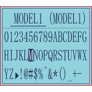
Model Name “NAME”
RC4GS V3 stores model memories for 30 models. Each model memory can be named separately according to user’s requirement.
Factory default name: MODEL1
(1) Long press «Exit» and «Enter» button simultaneously for one second to enter the function menu of RC4GS V3. Press «Inc(+)» button at the bottom of the screen to move the cursor to «18. NAME».
(2) Press “Enter” button to get into NAME function interface, the first character of current name will blink, and the blinking character can be reset. The common use characters appear at the bottom of the screen, use “Dec(-)” or “Inc(+)” button to choose the character you desired.Press“Enter” button again, the next character of current name will blink. Reset other characters of current name in same manner.
(3) After accomplishment of naming, all characters of current name will stop blinking, the new name will be stored automatically.
(4) When ending setting,return to the initial screen by pressing“Exit”button twice.(the new setting model name will appear on the initial screen)
ALARM(Safety alarm for low voltage and Signal strength )
Each model can independently set low voltage and RSSI value alarms, but the alarm functions of RATE and temperature are not yet available.
When the voltage of the transmitter, receiver, vehicle battery, and RSSI signal strength are lower than the set value, there will be a text displayed on the transmitter screen and a «didi» sound dual alarm prompt to remind you.
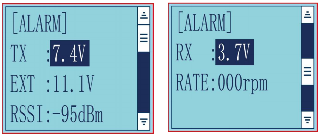
You can set the value in the «ALARM» menu: Press “Exit” and “Enter”button at the same time to enter menu, select the «19. ALARM» option, press “Enter”button to access the “ALARM” function interface. The transmitter default alarm voltage is 7.2V, and it can be customized on 2-4S battery .The receiver default alarm voltage is 4.0V, and the vehicle battery default alarm voltage is 11.1V.
The default alarm voltage of single-chip battery is 3.7V. For example, if you use a 3S lithium battery for your model, then the low voltage alarm value should be set to 11.1V (3.7V×3S). The setting method of transmitter and receiver is the same.
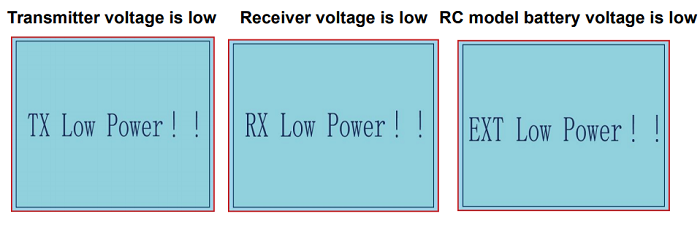
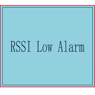
The RSSI alarm value is turned off by default. Users can set it as the RSSI value corresponding to the farthest safe distance of the actual control. For example, the farthest remote control distance is 400 meters, the corresponding RSSI value is -85dBm, then you can set the RSSI alarm value as -85dBm. When the vehicle is running, if the transmitter battery or vehicle battery is exhausted, or the RSSI signal is week, the vehicle will lose control. Therefore, when the alarm sounds, please stop driving immediately and take the vehicle back, check the cause of the alarm, and deal with it properly. The alarm prompt is as below:
Gyro Sensitivity “GYRO”
This function is available to set gyro sensitivity and VR mixing ON or OFF.
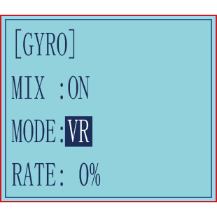
When MIX set OFF, gyro is disabled while when MIX set ON, you can adjust gyro sensitivity STD or VR. STD is adjusted on screen and VR is default CH3.
In normal mode (STD), range of sensitivity is 0%-100%.
(1) Enter the menu, use Dec(-) and Inc(+) to select options for gyro sensitivity.
(2) Press the key button “Enter” to enter sub-menu gyro sensitivity.
(3) Press “Enter” again, the initial value will start flashing, then use Dec (-) and Inc (+) to change the value.
(4) Press the button key “Enter”, the value stops flashing, the setting is finished now.
(5) «Mode»and «Rate» can also be set by the same step.
(6) Press button key “Exit” to be back to initial screen.
Fail Safe “F/S”
This function is set by servo, throttle, CH3, CH4, and CH5.
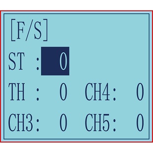
Option:
ST: Steering(CH1)
TH: Throttle(CH2)
CH3: Channel3(VR)
CH4: Channel4(SWA)
CH5: Channel5(SWD)
RANGE:
Servo: -100~+100
Throttle: -100~+100
CH3: -100~+100
CH4: -100~+100
CH5: -100~+100
Initial value: 0
(1) Enter the menu, use “Dec (-)” and “Inc (+)” to select options to set.
(2) Press the button key “Enter” to enter menu.
(3) Use “Dec (-)” and “Inc (+)” to select SERVO, then press “Enter”. Now the initial value
of SERVO will start flashing, use handle to change the value.
(4) Press the button key “Enter”, the value stops flashing, now the value of SERVO is set.
(5) THROTTLE is to set by the trigger.
CH3 is to set by VR controller.
CH4 is to set by the button switch.
CH5 is to set by the button switch.
(6) Press “Exit” two times to back to initial screen.
Subsidiary ID “ID SEED”
ID SEED function means designating a subsidiary ID among multiple binding receivers to realize the control. There are totally 10 independent subsidiary IDs can be stored. The four numbers displayed at the bottom of the screen are the independent ID codes of this transmitter.
For example, RC4GS V3 has completed the binding with 10 different boats and the setup of respective parameters. Turn on the ID SEED function, select ID.1 boat and drive it to the central of water but it stops working unexpectedly. Then we can change to the ID.2 boat (or any other subsidiary ID boat preferred) and control it independently to rescue ID. 1 boat instead of controlling both boats at the same time, which makes the rescue more difficult. Unlike traditional binding mode, independent ID can easily realize rescuing stalled boat in the water caused by various reasons.
Press EXIT and ENTER simultaneously to enter MENU=>press Inc(+)/DEC(-) to highlight “22. ID SEED=>Press ENTER => Change the MODE from OFF to ON=> set the subsidiary ID number=> complete biding and parameters setting.
Once finished , the corresponding ID number will be displayed on the RC4GS V3 main interface .
DSC port setting “DSC”
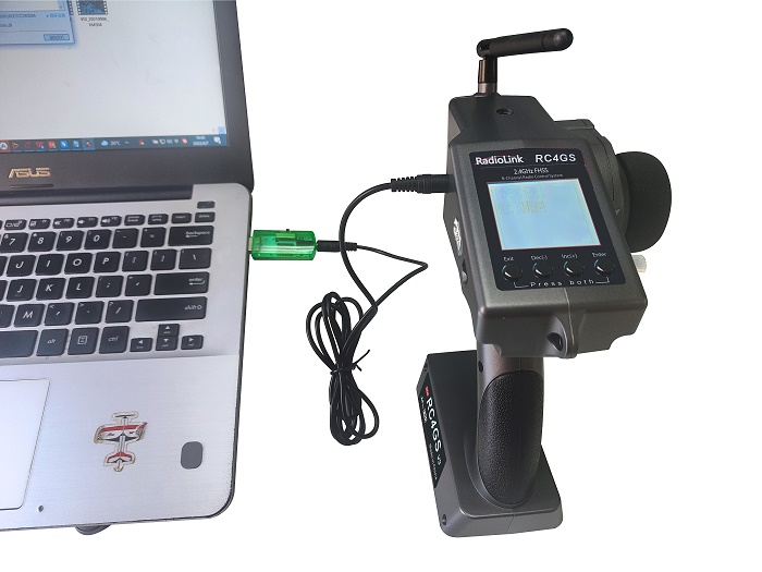
The DSC port on the left side of RC4GS V3 serves 2 purposes:
1. Connect to the simulator or TBS Crossfire,
2. Connect to FPV goggles with head track function.
DSC is for the function of the DSC port on the left side of the transmitter. There are two modes to choose from: simulator mode and head track mode.
Simulator mode: If you need to connect simulator or TBS Crossfire to the DSC port of RC4GS V3, please select the mode as: simulator.
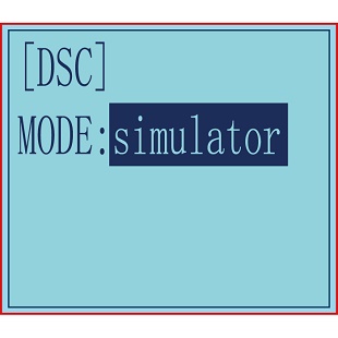
When connecting the simulator, insert one end of the standard audio head of the simulator into the DSC port of RC4GS V3, and follow the steps in the simulator instruction manual to calibrate and operate the transmitter in the simulation software. The following picture is for reference. (Please refer to the video for the method of connecting RC4GS V3 to TBS Crossfire:
https://www.youtube.com/watch?v=6vt5QexQSQs
Head track mode: If you need to connect FPV goggles with head track function to the DSC port of RC4GS V3, please set the mode to: head track.
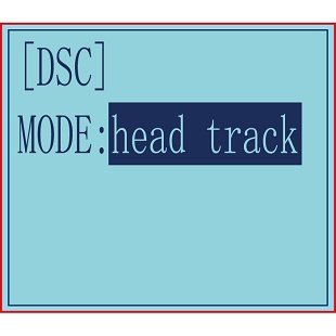
Then directly insert one end of the standard audio head of the FPV goggles into the DSC port of the remote control, and the other end into the Track Out port of the FPV goggles.
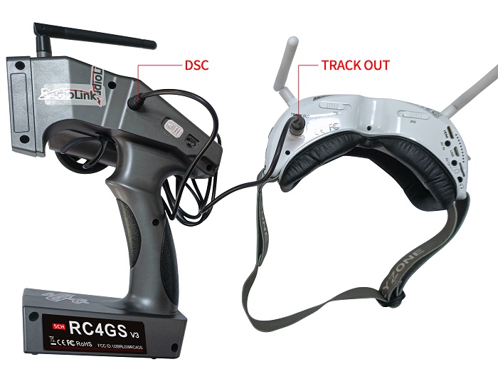
When the DSC mode is selected as head track, the DSC port of RC4GS V3 outputs in channel 5 and channel 6 by default. So you need to update the head track firmware of RC6GS. Then connect the roll servo and pitch servo used to control the pan-tilt to the pins of R6FG receiver in channel 5 and channel 6, and then swing the FPV goggles up and down or left and right, and the servos of the corresponding channel will swing accordingly.
Note: If you want to realize the head track function, please make sure the FPV goggles used support head track function.
Please refer to the video for The connection method of RC4GS V3 to FPV goggles:
https://www.youtube.com/watch?v=COYvtdWBTdY&t=130s
Timer Setting “TIMER”
TIMER function is mainly used for game timing, and for daily training.
Enter the setting interface: Long press "Exit" and "Enter" button simultaneously for one second to enter the function menu of RC4GS V3. Press "Inc(+)" button at the bottom of the screen to move the cursor to "24. TIMER", and then press " Enter” button to enter the function setting interface.
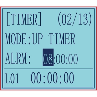
Mode: Timer mode, you can choose "UP TIMER" or "DOWN TIMER".
UP TIMER: After triggering the timing function, the timing number will count upwards.
DOWN TIMER: After triggering the timing function, the timing numbers will count down.
Alarm: The timer starts. When it reaches the set time, the transmitter starts to alarm. In the countdown 20 seconds, it starts to alarm every 1 second. In the countdown 10 seconds, it starts to alarm twice every 1 second. When the alarm time is reached, the transmitter will give a alarm. If the switch is not toggled now, the timing will continue. The default alarm time is 8 minutes. The alarm time can be set according to actual needs
START: Select a switch or button used to trigger the timing function. You can choose SWA, SWD, TH (throttle trigger), and the lock mode of the two switch buttons.
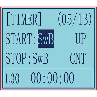
NULL means that the timing function is not enabled. If the switch is set to SWA, SWD or their lock modes, you can select UP (up), CNT (central), or DOWN (down) for the position of the switch to trigger the timing function.
If the start switch is TH (throttle trigger), you can set the throttle rate to 0%-100%, and the timing function will be triggered when the throttle trigger is pushed to the set rate.
STOP: It is used to stop the timing function. The setting method is the same as the above "START" setting. When the number of laps set is greater than 1, the number of laps will automatically increase by 1 lap each time it stops.
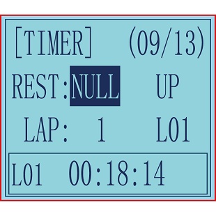
RESET: By toggling the switch set here, all the previously generated timing values will be cleared.Alarm values and laps are retained. The switch setting method is the same as the above "START" setting.
Note:
1. When triggering the timing function, please do not put the switch in the stop or reset position, otherwise the timing function cannot be activated.
2. When the switch is not enough, there are 2 ways to reset all timings: a. By setting the «alarm» value, all timings can be reset. b. All timings can be reset by setting the «mode» value.
LAP: used to set the number of laps required for timing, 1-30 lap numbers can be set;
Display laps: used to display the lap corresponding to the current timing.L01-L30 can be selected. For example, when it is L02, the timing below correspond to Lap 2. When the number of laps set is greater than 1, the number of laps will automatically increase by 1 lap each time it stops.
How to check the timing of each lap: move the cursor to: L01-L30, press the "Enter" button, the cursor starts to blink, and then press the "Dec(-)" or "Inc(+)" buttons at the bottom of the screen to select the laps to check the timing time. The corresponding timing lap and timing will be displayed in the box below.
Display: CURRENT, the ON or OFF status of the timing function is only displayed in the function menu of "Timer".
HOME PAGE, the ON or OFF status of the timer function is displayed both in the "Home Page" and "Timer" function menu of the transmitter at the same time.
Factory Reset “RESET”
RESET- Data reset function:
All the data for any model memory can be reset to original factory defaults. Often this function is done to get a “fresh start” and clear the memory before inputting new model settings.
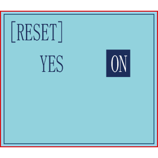
(1) Enter the function menu and use “Dec(-)” or “Inc(+)” button to access RESET function.
(2) Press “Enter” button to get into RESET function interface, the symbol “YES” will blink.
(3) Press “Enter” key, the symbol “YES” will stop blinking, and the transmitter will make three beeps. Then it will return to the initial screen automatically. Now the model data is reset to the initial setting that is the default value set at the factory.
CAUTION: Resetting the current model memory will permanently erase ALL programming information for that model. The data cannot be recovered. Do not reset the model unless you are certain you want to clear-out that memory and start from scratch.
Thank you again for choosing our product.

Настало время изучить аппаратуру Radiolink RC4G. Сегодня пройдусь по всем настройкам меню, заодно набросаю статью, чтобы в дальнейшем не затруднять себя чтением мануалов.
Сразу предупреждаю, что в описании могут быть ошибки и неточности. Это все-таки моя первая аппаратура такого рода.
Для того чтобы попасть в меню настроек Radiolink RC4G необходимо нажать одновременно две кнопки «EXIT» и «ENTER».
Увидим такую картинку:
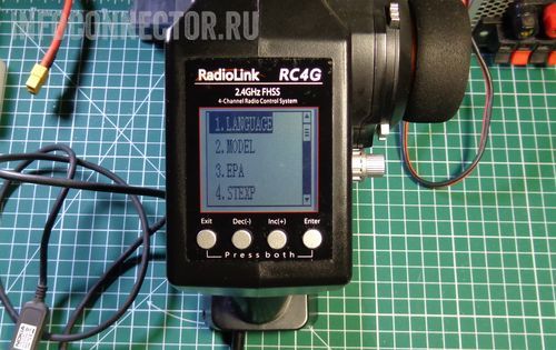
LANGUAGE – Выбор языка интерфейса
Русского языка в списке, конечно же, нет.
MODEL – Выбор модели
В данной аппаратуре можно сохранить 10 конфигураций для управления моделями. Каждая конфигурация сохраняется под своим уникальным именем (см. пункт меню «NAME»). Это сделано для того чтобы вы могли управлять сразу несколькими радиоуправляемыми моделями с одного пульта.
EPA – Регулировка конечных точек
Эта функция служит для регулировки уровня сигнала в крайних точках движения управляющих рычагов.
У каждого элемента управления аппаратуры есть две крайние точки движения и среднее положение. Уровень сигнала в среднем положении соответствует 0%, уровень сигнала в крайних точках соответствует 120% (значение по умолчанию).
К примеру, вы считаете, что максимальный уровень газа слишком велик и его необходимо уменьшить. Для этого заходим в меню «EPA». За газ отвечает второй канал на передатчике – «Throttle trim». Две крайние точки этого канала регулируются в пунктах TH-FWD (Throttle – Forward «газ») и TH-BRK (Throttle – Break «тормоз»). Уменьшаем уровень сигнала на «TH-FWD» до 50%. Теперь, если выжать полный газ, машинка будит двигаться значительно медленнее.
Так же можно уменьшить скорость заднего хода. За нее отвечает крайняя точка второго канала TH-BRK (Throttle – Break).
Можно уменьшить угол поворота колес. Причем в правую и левую сторону по отдельности.
Описание крайних точек:
- ST-LFT: Руль, крайнее левое положение;
- ST-RGT: Руль, крайнее правое положение;
- TH-FWD: Газ, движение вперед;
- TH-BRK: Газ, движение назад;
- 3C-LFT: 3-й канал, крайнее левое положение;
- 3C-RGT: 3-й канал, крайнее правое положение;
- 4C-UP: 4 канал, верхнее значение;
- 4C-DWN: 4 канал, нижнее значение.
STEXP – Steering EXP – Экспоненты для рулевого управления
Эта опция используется для изменения чувствительности руля около нейтрального положения и вблизи крайних точек. Она регулируется в пределах [-100;100].
- От -100 до 0 – Чувствительность около нейтрального положения руля становится ниже, около крайних положений чувствительность возрастает.
- 0 – Чувствительность во всем диапазоне движения руля одинакова.
- От 0 до 100 – Чувствительность около нейтрального положения руля становится выше, около крайних положений чувствительность уменьшается.
STSPD – Steering Speed – Скорость работы рулевого управления
Замедляет скорость работы рулевого управления. Т.е. добавляется временная задержка в работу рулевого колеса. Эту функцию полезно использовать, когда машина часто уходит в занос.
Два элемента для управления:
- TURN – поворот рулевого колеса.
- RETURN – возврат рулевого колеса.
THEXP – Throttle EXP – Экспоненты для рычага газа и тормоза
Здесь можно регулировать чувствительность рычага отвечающего за газ и тормоз.
Три алгоритма настройки чувствительности газа (разгона): CRV (кривая по 5 точкам), VTR (кривая по одной точке), EXP (экспонента).
Выбор активного алгоритма осуществляется в меню MODE: MODE/ACT – включен, MODE/INH – выключен.
Чувствительность тормоза настраивается по экспоненте.
THSPD – Throttle Speed – Скорость работы рычага газа
Замедляет скорость работы рычага газа. При включении получаем что-то типа антипробуксовочной системы. Применяется на скользкой дороге и для экономии заряда батареи.
Функция работает только на нажатие рычага газа, на отпускание и торможение не задействована.
MODE:
- OFF – опция отключена
- SPEED1 – алгоритм настройки #1
- SPEED2 – алгоритм настройки #2
A.B.S – A.B.S. Function «A.B.S» – Антиблокировочная система
Функция аналогична системе ABS (антиблокировочная система) на настоящих машинах. Применяя ее, мы увеличиваем степень управляемости машиной при торможении.
Опция имеет массу настроек, с которыми пока не разбирался.
ACCEL – Throttle Acceleration – Начальное ускорение
Функция, которая регулирует начальное ускорение машинки при выходе рычага газа из нейтрального положения. Или, если проще, устанавливает начальный уровень газа.
- FWRD: Начальная скорость при движении вперед.
- BRAK: Начальная скорость при движении назад.
IDLUP – Idle-Up – Холостые обороты ДВС
Поднимает обороты холостого хода двигателя бензинового автомобиля.
SUBTR – Subtrim – Субтриммеры
Регулирует центральное положение рычагов управления.
REV – Servo Reverse – Установка реверса
Реверсирует работу каналов. Например, если вы нажимаете на газ, а машинка включает задний ход, то установка реверса на этот канал исправит ситуацию.
D/R – Steering Dual Rate/Throttle Dual Rate
Данная опция позволяет одновременно регулировать положение сразу двух крайних точек канала. Если я правильно понял, то регулировка осуществляется пропорционально значениям EPA.
- Steering D/R – Рулевое управление.
- Throttle D/R – Газ.
ATL – ATL Function
Регулировка силы торможения.
PMIX – Programmable Mixes – Микширование каналов
Эта функция позволяет применять миксы между каналами.
AUX – Channel 3 and Channel 4 Position
Устанавливает функции на третий и четвертый канал.
NAME – меняем имя радиоуправляемой модели
Здесь можно задать имена нашим моделям. Выбор текущей модели осуществляется в меню «MODEL».
ALARM
Оповещение о низком заряде аккумулятора аппаратуры.
GYRO – Настройка гироскопа
Здесь включается и настраивается действие гироскопа.
F/S – Fail safe – Действия при потере связи
Здесь настраиваем поведение модели при потере связи между приемником и передатчиком.
REST – Reset – Сброс всех параметров на заводские настройки
Здесь осуществляется полный сброс аппаратуры на заводские настройки.
Продолжаю короткие обзоры для любителей р/у моделей формата RTR/ARR/KIT – на этот раз это RadioLink RC4GS, четырехканальная аппаратура (2.4GHz) с приемником в комплекте RadioLink R6FG Receiver.
Неплохая недорогая аппаратура, которая поможет развить функциональность р/у моделей.
В прошлом обзора задавали вопросы по поводу выбора р/у пульта — я сделал еще один короткий обзор на свою аппаратуру RadioLink RC4GS, которая идет с приемником R6FG (на 6 каналов). Это простая, но хорошая (дешевая) аппаратура (пульт) на четыре канала и в виде пистолета-ручки. Обычно берут для р/у автомобилей всевозможных типов, так как штатные пульты похожие, и для лодок.

Описание:
Model: RadioLink R4GS
Power Supply: 2S-4S Lipo Battery
Operate current: lower than 80-120mA.
Distance: more than 400M ground.
LED screen: 128 * 64 resolution, LCD back light.
10 modes memory storage
Size: 213 * 117 * 115.5mm
Reciever: RadioLink R6FG
Frequency: 2.4GHz ISM band (2400MHz~2483.5MHz)
Size: 35 * 20 * 13mm
Channel: 6
Model: cars / boats
Modulation mode: GFSK
Spread spectrum: FHSS
10 modes memory storage
Antenna length: 200mm
Control distance: more than 400 meters
LCD screen: 128 * 64 resolution, LCD back light
Power supply: 4.8~10.0V DC
RF power: <10dbm
Channel resolution: 4096
Work current: 30mA
Compatible with transmitters: RC6GS, RC4GS, RC4G, RC3S, T8FB
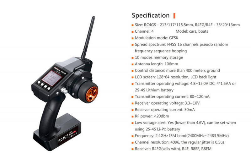
Эту аппаратуру мне подарили, вернее дали денег, чтобы я себе купил.
Я считаю, что выбор неплохой, так как к четырехканальному пульту идет сразу 6-канальный приемник.
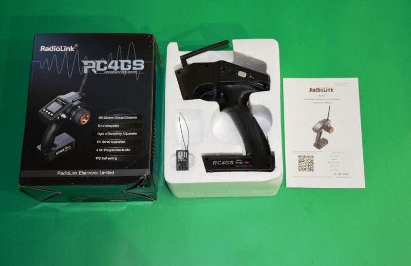
С виду аппаратура похожа на штатные пульты от р/у машинок — Это Pistol-type (Grip-type) пульт, с поворотным колесом.
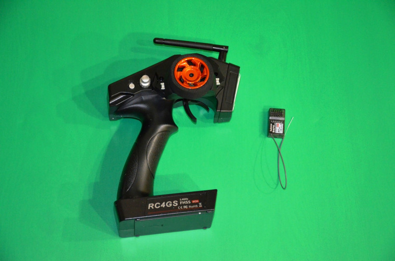
Антенна складывается, не очень длинная, в сложенном состоянии также работает.
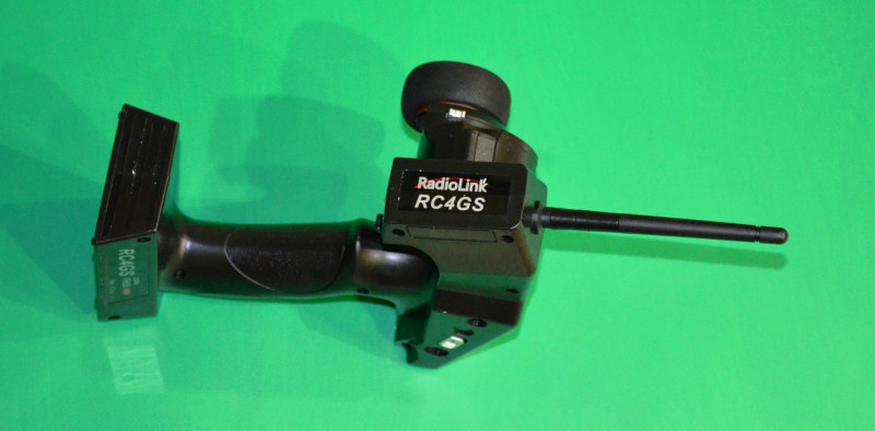
Вот так выглядит пульт RC4GS

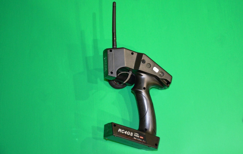
Внутри пластиковой антенны прячется провод.
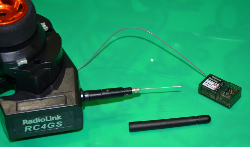
Приемник в комплекте на 6 каналов, т.е. работает с несколькими типами пультов (RC6GS, RC4GS, RC4G, RC3S, T8FB)
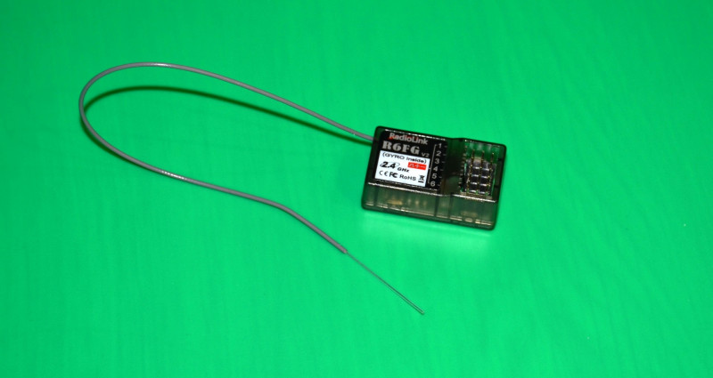
В пятке прячутся 4 батарейки АА для питания пульта.
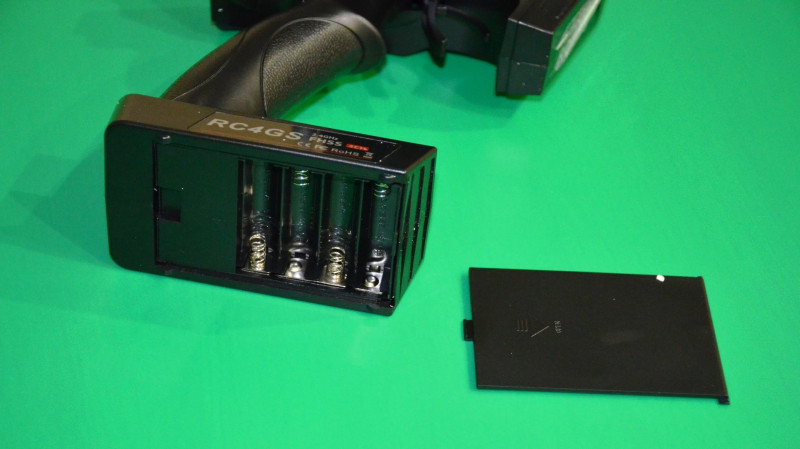
Есть USB коннектор для подключения к компьютеру (прошивки). Рядом — включение и выключение.

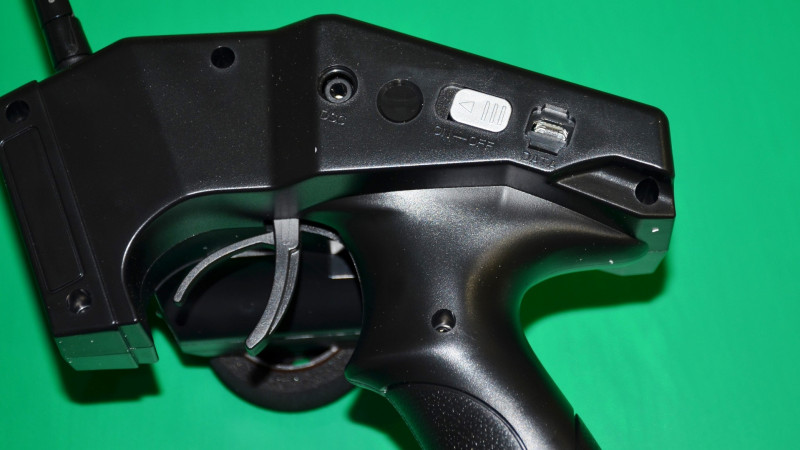
С другой стороны на корпусе есть подстройка каналов (триммирование)
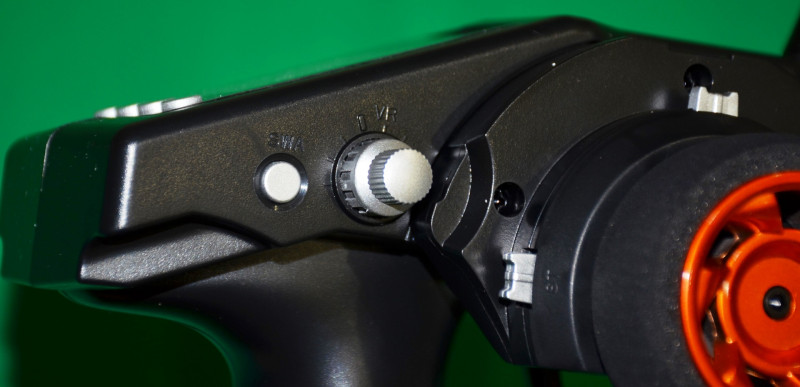
Дисплей квадратный, небольшой.
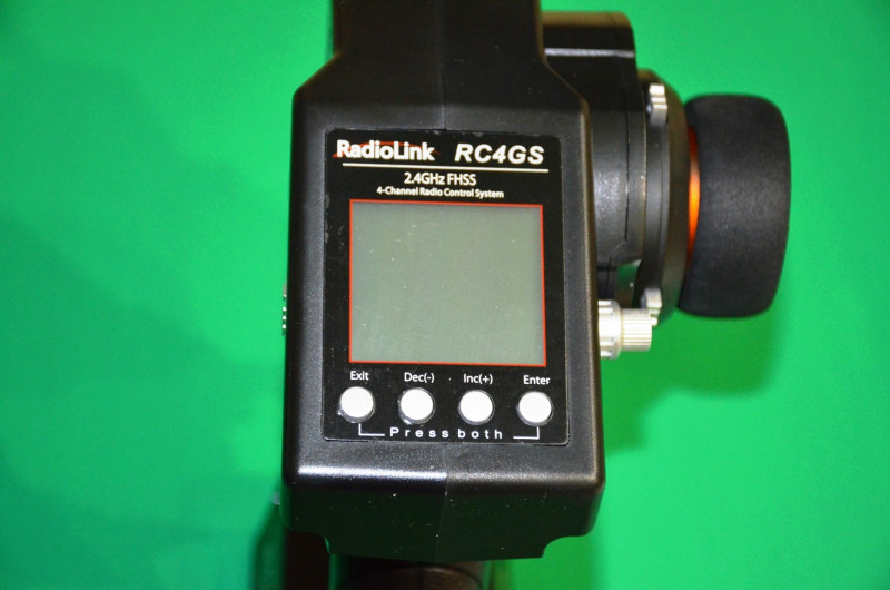
Я использовал аккумуляторы АА, с ними вроде нормально работает.
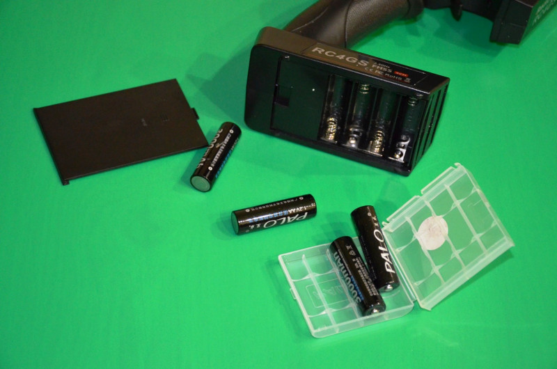
На дисплее отображаются два основных пропорциональных канала.
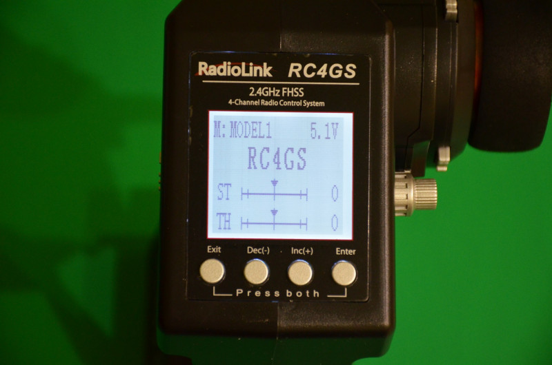
Видна работа (индикация) газа (заслонки)
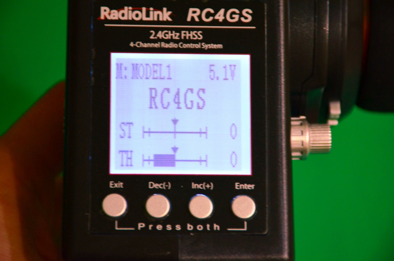
И работа рулевого управления
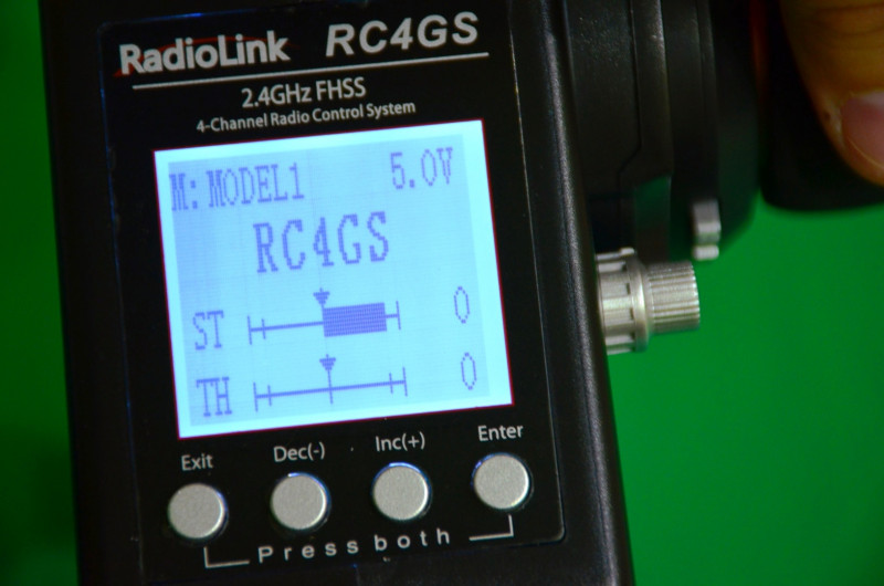
Прошлый раз очень просили рассказать про подключение к р/у модели — это не сложно.
На картинке из инструкции видно, что и куда подключать.
Питание приемника берется из канала с двигателем (с встроенного источника в ESC контроллер двигателя) по тем же проводам (S-G-Vcc).
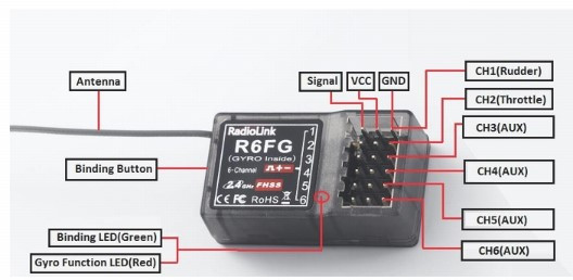
Сервопривод просто подключаем на канал рулевого (CH1)
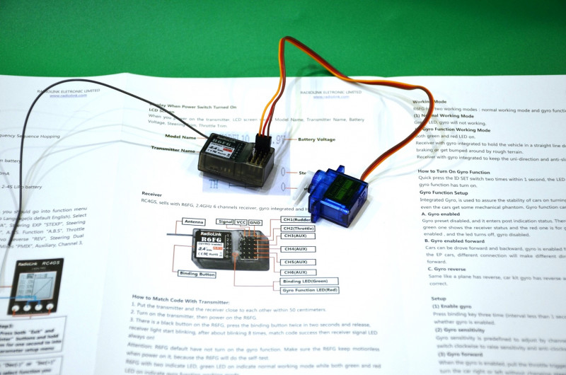
Подключаем разъемы в приемник, его закрепляем внутри модели, прячем антенну (Провод), укладываем провода.
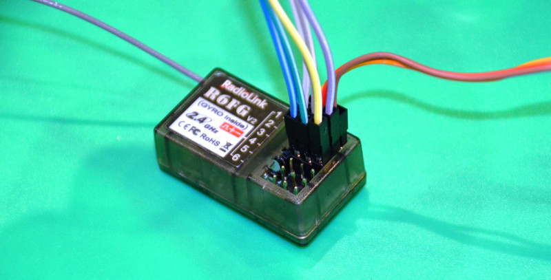
Естественно, это все вместо штатной платы приемника.
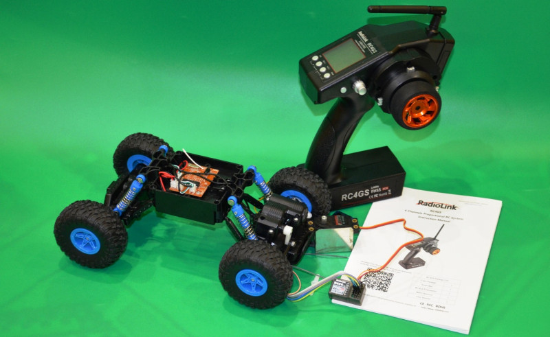
Для подключения нужна будет плата-контроллер коллекторного двигателя. Вот ее подключение.
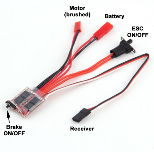
Для наглядности — показываю эту же схему, собранную вне машинки. Контроллер двигателя + приемник + 2S аккумулятор + сервомашинка.
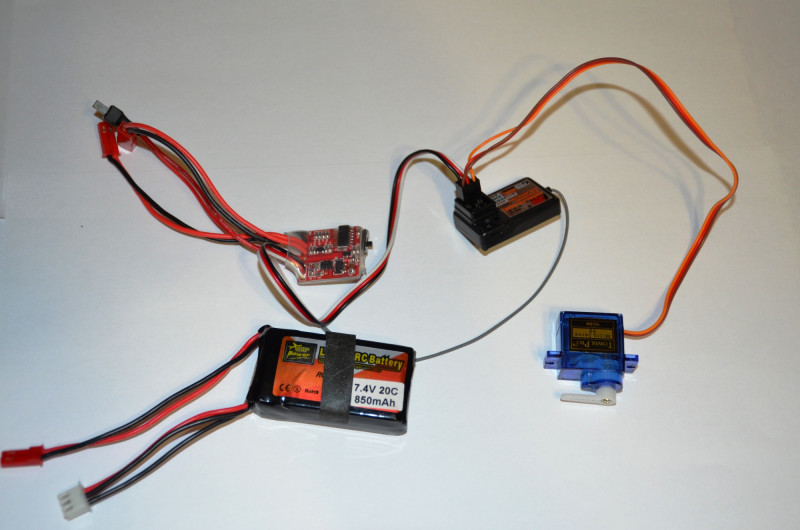
Гифка с работой схемы. Показаны два канала — рулевой и газ (на ESC загорается индикация сигнала).
Обзор короткий, надеюсь, на вопросы я ответил.
Это очень неплохая аппаратура от RadioLink на 4 канала, с приемником в комплекте. И недорогая. Можно остастить этой аппаратурой свой монстр-трак, краулер, танк, багги и т.п. Любую самостоятельно собранную машинку или переделать одну из покупных. Даже, если вы потеряли или сломали штатный пульт, всегда можно купить и поставить что-то подобное. Четыре канала — два на рулевое и газ, остальное на навесное оборудование (Свет, лебедка, повороты и так далее).
RadioLink RC4GS 2.4GHz 4CH пульт + приемник R6FG сейчас можно купить с купоном RADLIN. Цена неплохая, $43.99.
Дополнительная информация
Ссылка на прошивку пульта.
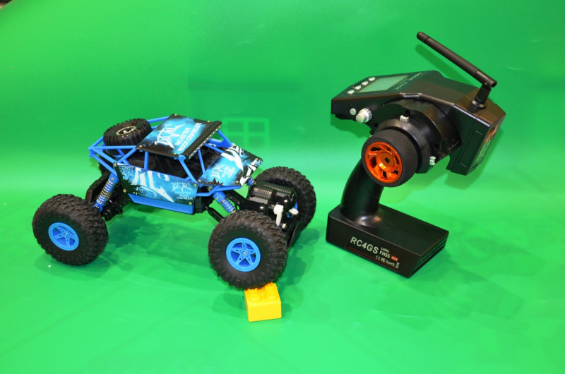
-
Пятиканальный цифровой пульт радиоуправления RC4GS V3 пистолетного типа с шестиканальным приемником R6FG с встроенным гироскопом. Благодаря использованию в передатчике промышленной микросхемы ARM M4 обеспечивается превосходная защита от помех и дальность действия управления на расстоянии до 400 метров по земле. Пульт управления RC4GS V3 является идеальным передатчиком для всех типов радиоуправляемых автомобилей и лодок, представленных на рынке, включая одномоторные и двухмоторные модели, такие как гусеничные машины или танки.
Пульт управления RC4GS V3 имеет индикатор уровня принимаемого сигнала RSSI и в режиме реального времени при пользовании с приемниками R7FG/R8F отображает на своем ЖК-экране напряжение батареи модели в конфигурации до 8S (33,6 В) без необходимости использования дополнительного модуля. Имеется приятный сюрприз для водителей краулеров. Чтобы точно контролировать дроссельную заслонку на спуске, система круиз-контроля RC4GS V3 помогает водителю легко установить оптимальную скорость движения.
За 19 лет исследований и разработок в соответствии с отзывами пользователей, в RC4GS V3 добавлено множество новых функций, требуемых потребителю. RC4GS V3 может сохранять настройки параметров максимум на 30 моделей и привязать к передатчику до 10 различных приемников. Кнопочный переключатель можно настроить для активации двойных расходов во время маневрирования автомобиля, это помогает быстро переключать D/R во время движения, без необходимости каждый раз смотреть на ЖК-дисплей и нажимать все меню, а двойное программируемое управление микшированием обеспечивает смешивание контроля передних колес с задними, что позволяет уменьшить радиус поворота.
Мультифункциональный порт DSC передатчика RC4GS V3 можно использовать для подключения симулятора, для функции отслеживания положения головы при использовании FPV очков, либо для подключения модуля TBS Crossfire, который значительно увеличивает дальность действия управления, а для контроля за временем прохождения круга в передатчике RC4GS V3 имеется таймер. Стандартный приемник R6FG с встроенным гироскопом и поддержкой сервоприводов высокого напряжения обеспечивает лучший контроль с использованием гироскопической стабилизации. Чувствительность гироскопа можно настроить с помощью каналов STD или CH3.
Основываясь на отзывах сотен опытных гонщиков, в передатчике RC4GS V3 модернизирован курок газа, изменена толщина рукоятки и оптимизировано расположение каждого переключателя, что делает вождение более комфортным. Батарейный отсек RC4GS V3 с широким допуском рабочего напряжения легко адаптируется к различным аккумуляторным батареям. Можно использовать 6 батареек AA, либо LiPo или Lithium 18650 аккумуляторы в конфигурации 2S-4S. Универсальный разъем JST со специальной платой для защиты от подключения с обратной полярностью обеспечивает защиту жизненно важных компонентов передатчика. Прошивка RC4GS V3 легко обновляется с компьютера через USB-кабель. Интуитивно понятные программные подсказки легко проведут вас через весь этот процесс.
- 5 каналов для автомобилей, лодок, гусеничных машин и роботов
- Дистанция управления до 400 метров
- Память на 30 моделей
- Система круиз-контроля
- Встроенный гироскоп
- Поддержка HV Servo
- Функция отслеживания положения головы для FPV
- Возможность активирования двойных расходов с переключателя
- Таймер
- Защита от перемены полярности
Приемник R6FG
- Размер: 35*20*13 мм
- Вес: 6 г
- Длина антенны: 205 мм
- Кол-во каналов: 6
- Частота: диапазон ISM 2,4 ГГц (2400 МГц ~ 2483,5 МГц)
- Режим расширенного спектра FHSS: 67 псевдослучайный каналов
- Диапазон напряжения: DC 3~12В
- Рабочий ток: 30 мА (в зависимости от напряжения питания)
- Дальность действия управления: 400 метров по земле
- Гироскоп: встроенный в приемник
- Совместимые передатчики: T8S/T8FB/RC6GS V2/RC4GS V2/RC6GS/RC4GS
Комплект поставки:
- Пульт управления RC4GS V3
- Приемник R6FG
Необходимо докупить:
- 6х АА батарейки в пульт.
Габариты упаковки 26х14х20 см 0,65кг.