-
Contents
-
Table of Contents
-
Bookmarks
Quick Links
INSTRUCTION MANUAL
VHF TRANSCEIVER
iF110
UHF TRANSCEIVER
iF210
Related Manuals for Icom IC-F110
Summary of Contents for Icom IC-F110
-
Page 1
INSTRUCTION MANUAL VHF TRANSCEIVER iF110 UHF TRANSCEIVER iF210… -
Page 2: Important
NEVER instruction manual contains important operating instructions connect the transceiver to a power source of more for the IC-F110 VHF TRANSCEIVER and IC-F210 UHF than 16 V DC such as a 24 V battery. This connection will ruin TRANSCEIVER. the transceiver.
-
Page 3: Table Of Contents
I Fuse replacement …………..17 I Cleaning …………….. 17 CAUTION: Changes or modifications to this transceiver, not ex- 5 OPTIONS ………………. 18 pressly approved by Icom Inc., could void your authority to operate 6 CE ………………19–20 this transceiver under FCC regulations.
-
Page 4: Panel Description
PANEL DESCRIPTION I Front panel q AF VOLUME CONTROL KNOB e UP/DOWN [ ] KEYS ➥Push to select the operating channel. Rotate the knob to adjust the audio output level. ➥Can be programmed for one of several functions by your •…
-
Page 5: I Function Display
PANEL DESCRIPTION I Function display t DEALER-PROGRAMMABLE KEYS [P0] to [P3] Desired functions can be programmed independently by your dealer. y MICROPHONE CONNECTOR Connect the supplied microphone or optional DTMF micro- phone for SmarTrunk II operation here. NEVER connect non-specified microphones. The pin assignments may be different and the transceiver may be damaged.
-
Page 6: I Programmable Function Keys
[P3], [ ] and [ ] programmable function keys. Displays the CH number, 5-tone indication, DTMF num- Consult your Icom dealer for details concerning your trans- bers, Audible indication, etc. ceiver’s programming. NOTE: When the alphanumeric display blinks and trans-…
-
Page 7
PANEL DESCRIPTION ¡ ¡ SCAN START/STOP KEY ¡ ¡ MONITOR KEY Push this key to start scanning; and push again Activates one of (or two of) the following functions SCAN A MONI to stop. on each channel independently: SCAN B •… -
Page 8
PANEL DESCRIPTION ¡ ¡ OUTPUT POWER SELECTION KEYS ¡ ¡ CALL KEY Select the transmit output power temporarily, or Transmit a 2-tone, 5-tone code. CALL permanently, depending on the pre-setting. • Call transmission is necessary before you call another station depending on your signaling system. •… -
Page 9
PANEL DESCRIPTION ¡ ¡ SCRAMBLER KEY ¡ ¡ USER SET MODE KEY ➥ Push and hold to turn the voice scrambler func- Changes the contents of the items in the User Set SCRM tion ON. mode. Please refer to p. 10. ➥… -
Page 10: Operation
OPERATION I Turning power ON I Channel selection q Push [ ] to turn the power ON. Several types of channel selection are available. The meth- ods may differ according to your system setup. w If the transceiver is programmed for a start up passcode, input the digit codes as directed by your dealer.
-
Page 11: I Receiving And Transmitting
OPERATION I Receiving and transmitting D Transmitting notes RECEIVING: q Push [ ] to turn the power ON. • Transmit inhibit function w Push [ ] and [ ] to select a channel. The transceiver has several inhibit functions which restrict e When receiving a call, adjust the audio output level to a transmission under the following conditions: comfortable listening level.
-
Page 12: D Tx Code Channel Selection
OPERATION D TX code channel selection D DTMF transmission If the transceiver has a [TX CH] key, the display can be tog- If the transceiver has a [DTMF] key, the automatic DTMF gled between the operating channel number (or name) and transmission function is available.
-
Page 13: D User Set Mode
OPERATION D User set mode User set mode is accessed at power ON and allows you to set seldom-changed settings. In this case you can “cus- tomize” transceiver operation to suit your preferences and operating style. Entering the user set mode: q While pushing and holding [ ] and [ ], push [POWER]…
-
Page 14: Optional Smartrunk
OPTIONAL SmarTrunk II™ OPERATION I SmarTrunk II™ and I SmarTrunk II™ operation conventional modes These features are enabled by a dealer and may not be avail- able in your system. Contact your dealer for details. This transceiver is capable of SmarTrunk II™ functions. D Placing a telephone call The optional UT-105 allows communication in conventional Enter the phone number followed by [1], [M].
-
Page 15: Emergency Call
OPTIONAL SmarTrunk II™ OPERATION D Terminating a call D System busy indication After completing a call, push [#] to disconnect (hang up). If all channels are busy, three low beeps sound after you initi- ate a call. Try the call again later. IMPORTANT!: If one person in the conversation termi- nates a call, all participants will be cut off.
-
Page 16: Connection And Maintenance
CONNECTION AND MAINTENANCE I Rear panel and connection Optional speaker Antenna (SP-22) R C A U T I O N ! N E V E R r e- red: move the fuse-holder from the DC power cable. NOTE: Use the terminals as shown below for the cable connections.
-
Page 17: I Supplied Accessories
CONNECTION AND MAINTENANCE I Supplied Accessories q ANTENNA CONNECTOR Connects to an antenna. Contact your dealer about an- tenna selection and placement. w MICROPHONE HANGER Connect the supplied microphone hanger to the vehicle’s KEY-STICKER ground for microphone on/off hook functions. (See p. 2) e DC POWER RECEPTACLE Connects to a 12 V DC battery.
-
Page 18: I Mounting The Transceiver
CONNECTION AND MAINTENANCE I Mounting the transceiver I Optional UT-105, UT-108 or UT-111 installation The universal mounting bracket supplied with your transceiv- er allows overhead mounting. Install the optional UT-105, UT-108 or UT-111 unit as follows: • Mount the transceiver securely with the 4 supplied screws q Turn the power OFF, then disconnect the DC power cable.
-
Page 19: I Optional Ut-109 Or Ut-110 Installation
CONNECTION AND MAINTENANCE I Optional UT-109 or UT-110 I Optional OPC-617 installation installation Install the OPC-617 as shown below. q Turn the power OFF, then disconnect the DC power cable. w Unscrew the 4 cover screws, then remove the bottom cover.
-
Page 20: I Antenna
CONNECTION AND MAINTENANCE I Antenna A key element in the performance of any communication sys- tem is an antenna. Contact your dealer about antennas and the best places to mount them. I Fuse replacement A fuse is installed in the supplied DC power cable. If a fuse blows or the transceiver stops functioning, track down the source of the problem if possible, and replace the damaged fuse with a new rated one.
-
Page 21: Options
OPTIONS SP-22 EXTERNAL SPEAKER Compact and easy-to-install. Input impedance : 4 Ω Max. input power : 5 W HM-100TN DTMF microphone. SM-25 Desktop microphone. UT-105 SmarTrunk II Logic Board Provides SmarTrunk II capabilities. UT-108 DTMF DECODER UNIT Provides pager and code squelch capabilities. UT-109/UT-110 (#02) VOICE SCRAMBLER UNIT •…
-
Page 22
DECLARATION OF CONFORMITY We Icom Inc. Japan 0168 1-1-32, Kamiminami, Hirano-ku Osaka 547-0003, Japan Declare on our sole responsibility that this equipment complies with the essential requirements of the Radio and Telecommunications Terminal Equipment Directive, 1999/5/EC, and that any applicable Essential Test Düsseldorf 18th Nov. -
Page 23
EN 60950 (August 1992 +A11) iv) EN 300 086-2 (March 2001) Signature v) EN 300 219-2 (March 2001) About e-marking: Detailed installation notes for Icom mobile transceivers to be fitted into vehicles are available. Please contact your Icom dealer or distributor. -
Page 24
< Intended Country of Use > A-6234H-1EU-q Printed in Japan 1-1-32 Kamiminami, Hirano-ku, Osaka 547-0003 Japan © 2002–2003 Icom Inc.
This manual is also suitable for:
Ic-f210
Specifications:465/465555-icf110.pdf file (14 Aug 2023) |
Accompanying Data:
Icom IC-F110 Transceiver PDF Instruction Manual (Updated: Monday 14th of August 2023 11:44:11 PM)
Rating: 4.2 (rated by 99 users)
Compatible devices: iF3002, IC-M59euro, IC-F6022, IC-T7A, UT-112, IC-X2A, PMR446, IC-F5360D.
Recommended Documentation:
Instruction Manual (Text Version):
(Ocr-Read Summary of Contents of some pages of the Icom IC-F110 Document (Main Content), UPD: 14 August 2023)
-
5, Icom IC-F110 2 1 PANEL DESCRIPTION t DEALER-PROGRAMMABLE KEYS [P0] to [P3] Desired functions can be programmed independently by your dealer. y MICROPHONE CONNECTOR Connect the supplied or optional microphone. NEVER connect non-specified microphones. The pin assignments may be different and the transc…
-
19, • SP-22 external speaker Compact and easy-to-install. Input impedance : 4 ø Max. input power : 5 W • HM-152/HM-152T/HM-148G/HM-148T hand microphones HM-152 : Hand microphone HM-152T : DTMF microphone HM-148G : Self ground heavy duty microphone HM-148T : Self ground heavy dut…
-
2, i IMPORTANT READ ALL INSTRUCTIONS carefully and com- pletely before using the transceiver. SAVE THIS INSTRUCTION MANUAL — This in- struction manual contains important operating instructions for the IC-F110 VHF TRANSCEIVER and IC-F210 UHF TRANS- CEIVER. EXPLICIT DEFINITIONS WORD DEFINITION RWARNING Personal…
-
6, 3 1 PANEL DESCRIPTION ■ Programmable function keys The following functions can be assigned to [P0], [P1], [P2], [P3], [ ] and [ ] programmable function keys. Consult your Icom dealer for details concerning your trans — ceiver’s programming. In the following explanations, programmable function names are brac…
-
13, Icom IC-F110 D User set mode User set mode is accessed at power ON and allows you to set seldom-changed settings. In this case you can “custom — ize” transceiver operation to suit your preferences and operat — ing style. Entering the user set mode: q While pushing and holding [ ] and [ ], push [POWER] to enter us…
-
9, 6 1 PANEL DESCRIPTION • SCRAMBLER KEY SCRM ➥ Push and hold to turn the voice scrambler func- tion ON. ➥ Push this key to turn the voice scrambler func- tion OFF. NOTE: • The optional UT-109 (#02) or UT-110 (#02) voice scrambler unit is required. — UT-109 : Non-rolling type. 32 codes are av…
-
Icom IC-F110 User Manual
-
Icom IC-F110 User Guide
-
Icom IC-F110 PDF Manual
-
Icom IC-F110 Owner’s Manuals
Recommended: Helia CGHC-1 Instant, SM122e, Road Stan XV17AT, 2345, Xsmall HD8743
Operating Impressions, Questions and Answers:
![]()
INSTRUCTION MANUAL
VHF TRANSCEIVER
iF110
UHF TRANSCEIVER
iF210

IMPORTANT
READ ALL INSTRUCTIONS carefully and com-
pletely before using the transceiver.
SAVE THIS INSTRUCTION MANUAL — This
instruction manual contains important operating instructions for the IC-F110 VHF TRANSCEIVER and IC-F210 UHF TRANSCEIVER.
EXPLICIT DEFINITIONS
|
WORD |
DEFINITION |
|
|
RWARNING |
Personal injury, fire hazard or electric shock |
|
|
may occur. |
||
|
CAUTION |
Equipment damage may occur. |
|
|
NOTE |
If disregarded, inconvenience only. No risk |
|
|
of personal injury, fire or electric shock. |
||
Icom, Icom Inc. and the 
 logo are registered trademarks of Icom Incorporated (Japan) in the United states, the United Kingdom, Germany, France, Spain, Russia and/or other countries. SmarTrunk II™ is a trademark of the SmarTrunk Systems, Inc.
PRECAUTION
RWARNING! NEVER connect the transceiver to an AC outlet. This may pose a fire hazard or result in an electric shock.
NEVER connect the transceiver to a power source of more than 16 V DC such as a 24 V battery. This connection will ruin the transceiver.
NEVER cut the DC power cable between the DC plug and fuse holder. If an incorrect connection is made after cutting, the transceiver might be damaged.
NEVER place the transceiver where normal operation of the vehicle may be hindered or where it could cause bodily injury.
NEVER allow children to touch the transceiver.
NEVER expose the transceiver to rain, snow or any liquids.
USE the supplied microphone only. Other microphones have different pin assignments and may damage the transceiver.
i

DO NOT use or place the transceiver in areas with temperatures below –25°C or above +55°C, or in areas subject to direct sunlight, such as the dashboard.
AVOID operating the transceiver without running the vehicle’s engine. The vehicle’s battery will quickly run out if the transceiver transmits while the vehicle’s engine OFF.
AVOID placing the transceiver in excessively dusty environments.
AVOID placing the transceiver against walls. This will obstruct heat dissipation.
AVOID the use of chemical agents such as benzine or alcohol when cleaning, as they damage the transceiver surfaces.
BE CAREFUL! The transceiver will become hot when operating continuously for long periods.
For U.S.A. only
CAUTION: Changes or modifications to this transceiver, not expressly approved by Icom Inc., could void your authority to operate this transceiver under FCC regulations.
|
TABLE OF CONTENTS |
|
|
IMPORTANT ………………………………………………………………………… |
i |
|
EXPLICIT DEFINITIONS ……………………………………………………….. |
i |
|
PRECAUTION ………………………………………………………………………. |
i |
|
TABLE OF CONTENTS ………………………………………………………… |
ii |
|
1 PANEL DESCRIPTION ………………………………………………….. |
1–6 |
|
■ Front panel ……………………………………………………………………. |
1 |
|
■ Function display …………………………………………………………….. |
2 |
|
■ Programmable function keys ……………………………………………. |
3 |
|
2 OPERATION ……………………………………………………………….. |
7–10 |
|
■ Turning power ON ………………………………………………………….. |
7 |
|
■ Channel selection …………………………………………………………… |
7 |
|
■ Receiving and transmitting ………………………………………………. |
8 |
|
DTransmitting notes ……………………………………………………….. |
8 |
|
DTX code channel selection ……………………………………………. |
9 |
|
DTX code number selection ……………………………………………. |
9 |
|
DDTMF transmission ……………………………………………………… |
9 |
|
DScrambler function ………………………………………………………. |
9 |
|
DUser set mode …………………………………………………………… |
10 |
|
3 OPTIONAL SmarTrunk IITM OPERATION …………………….. |
11–12 |
|
■ SmarTrunk IITM and conventional modes …………………………. |
11 |
|
■ SmarTrunk IITM operation ………………………………………………. |
11 |
|
4 CONNECTION AND MAINTENANCE ………………………….. |
13–17 |
|
■ Rear panel and connection ……………………………………………. |
13 |
|
■ Supplied Accessories ……………………………………………………. |
14 |
|
■ Mounting the transceiver………………………………………………… |
15 |
|
■ Optional UT-105, UT-108 or UT-111 installation ………………… |
15 |
|
■ Optional UT-109 or UT-110 installation ……………………………. |
16 |
|
■ Optional OPC-617 installation…………………………………………. |
16 |
|
■ Antenna ……………………………………………………………………….. |
17 |
|
■ Fuse replacement ………………………………………………………… |
17 |
|
■ Cleaning ……………………………………………………………………… |
17 |
|
5 OPTIONS ……………………………………………………………………….. |
18 |
|
6 CE ……………………………………………………………………………. |
19–20 |
ii

 1 PANEL DESCRIPTION
qAF VOLUME CONTROL KNOB
Rotate the knob to adjust the audio output level.
• Minimum audio level is pre-programmed.
wFUNCTION DISPLAY
Displays a variety of information, such as an operating channel number/name, 5-tone code, DTMF numbers and audible condition, etc.
NOTE: The above functions depend on pre-programming.
r
eUP/DOWN [ ]/[
]/[ ] KEYS
Push to select the operating channel.
Can be programmed for one of several functions by your dealer. (Same as [P0] to [P3] keys)
rPOWER SWITCH [POWER]
Push to turn the power ON and OFF.
•The following functions are available at power ON as options:
—Automatic scan start
—Password prompt
—Set mode
1
tDEALER-PROGRAMMABLE KEYS [P0] to [P3]
Desired functions can be programmed independently by your dealer.
yMICROPHONE CONNECTOR
Connect the supplied microphone or optional DTMF microphone for SmarTrunk IITM operation here.
NEVER connect non-specified microphones. The pin assignments may be different and the transceiver may be damaged.
D MICROPHONE
The supplied microphone has a PTT switch and a hanger hook.
•The following functions are available when the microphone is on or off hook:
—Automatic scan start when on hook.
—Automatic priority channel selection when off hook.
—Sets to ‘Inaudible’ condition (mute condition) when on hook.
—Sets to ‘Audible’ condition (unmute condition) when off hook.
PANEL DESCRIPTION 1
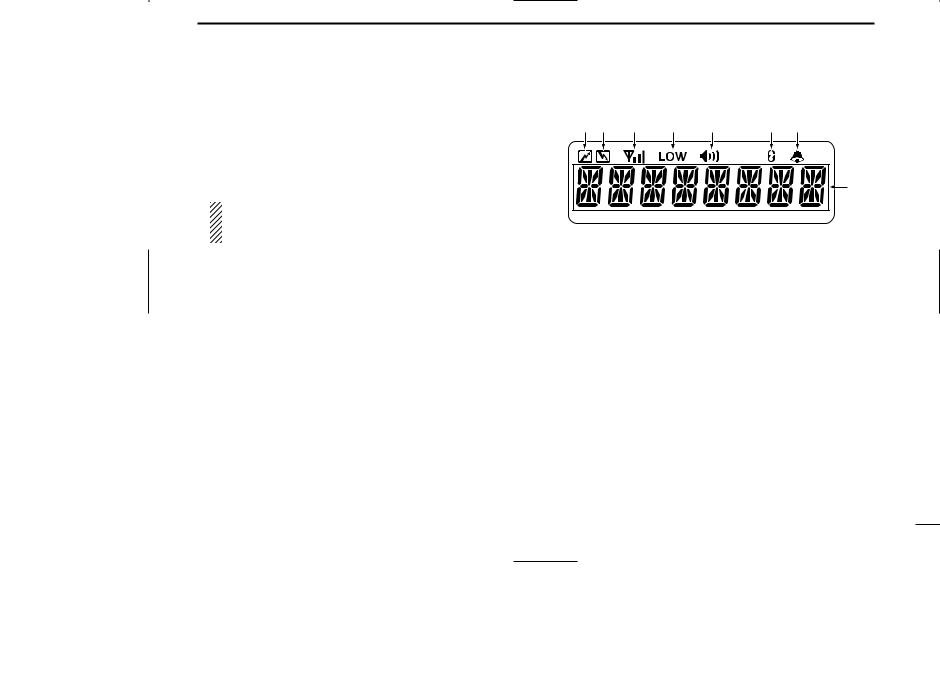
■Function display
|
q w |
e |
r |
t |
y |
u |
|
i |
qTRANSMIT INDICATOR
Appears while transmitting.
wBUSY INDICATOR
Appears while the channel is busy.
eSIGNAL STRENGTH METER
Indicates relative receive signal strength level.
rLOW POWER INDICATOR
Appears when low output power is selected.
tAUDIBLE INDICATOR
Appears when the channel is in the ‘Audible’ condition (unmute condition).
ySCRAMBLER INDICATOR
Appears when the scrambler function is activated. (Optional UT-109 (#02)/UT-110 (#02) SCRAMBLER UNIT is required.)
2

1 PANEL DESCRIPTION
u2/5TONE INDICATOR
Appears when the specified 2/5-tone call is received.
i ALPHANUMERIC DISPLAY
Displays the CH number, 5-tone indication, DTMF numbers, Audible indication, etc.
NOTE: When the alphanumeric display blinks and transmitting becomes impossible, check that the DC battery voltage has not dropped below 8 V or that the antenna is not tuned properly or the antenna connection is faulty.
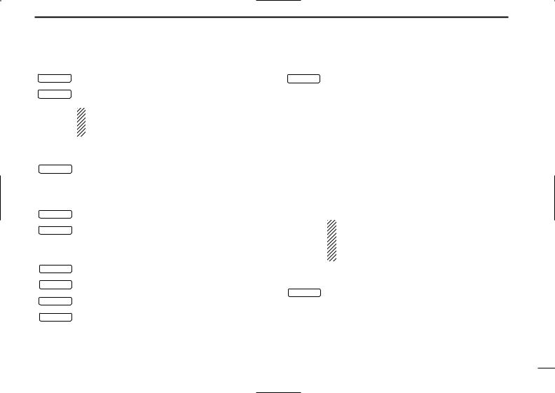
■Programmable function keys
The following functions can be assigned to [P0], [P1], [P2], [P3], [ ] and [
 ] programmable function keys.
Consult your Icom dealer for details concerning your transceiver’s programming.
In the following explanations, programmable function names are bracketed. The specific switch used to activate the function depends on programming.
¡ CH UP AND DOWN KEYS
|
CH UP |
Select an operating channel. |
|
|
CH DN |
Select a transmit code channel after pushing |
|
|
the [TX CH] key. |
||
Select a DTMF channel after pushing the
[DTMF] key.
Select a scan group after pushing and holding the [SCAN] key.
¡BANK KEY
BANK Select and determine a bank number.
•When the optional UT-105 is installed, push one or more times to select a channel bank for conventional channels or SmarTrunk II TM channels.
3
¡ SCAN START/STOP KEY
SCAN A Push this key to start scanning; and push again
to stop.
SCAN B
NOTE: Place the microphone on hook to start scanning.
Take the microphone off hook to stop scanning.
¡ SCAN TAG KEY
|
TAG |
Adds or deletes the selected channel to the scan |
|
|
group. |
||
|
¡ PRIORITY CHANNEL KEYS |
||
|
PRI A |
Push these keys to select priority A or priority B |
|
|
channel, respectively. |
||
|
PRI B |
||
|
¡ OPERATING CHANNEL KEYS |
||
|
CH1 |
Select an operating channel directly. |
CH2
CH3
CH4
PANEL DESCRIPTION 1
¡ MONITOR KEY
|
MONI |
Activates one of (or two of) the following functions |
on each channel independently:
•Push and hold the key to unmute the channel (audio is emitted; ‘Audible’ condition).
•Push the key to toggle between the mute and unmute conditions (toggles between ‘Audible’ and ‘Inaudible’).
•Push the key to mute the channel (sets to ‘Inaudible’ only).
•Push the key to unmute the channel (sets to ‘Audible’ only).
•Push the key after communication is finished to send a ‘reset code’.
NOTE: The unmute condition (‘Audible’ condition) may automatically return to the mute condition (‘Inaudible’ condition) after a specified period depending on the pre-setting.
¡ LOCK KEY
|
LOCK |
Push this key for 1 sec. to lock all programmable |
|
|
keys except the following: |
||
•[CALL] (incl. [CAL A] and [CAL B]), [MONI] and
[EMER] keys.
4

1 PANEL DESCRIPTION
¡ OUTPUT POWER SELECTION KEYS
|
H/L |
Select the transmit output power temporarily, or |
|
permanently, depending on the pre-setting. |
•Contact your dealer for the output power level for each selection.
¡TALK AROUND KEY
|
TA |
Turns the talk around function ON and OFF. |
•The talk around function equalizes the transmit frequency to the receive frequency for mobile-to-mobile communication.
¡WIDE/NARROW KEY
|
W/N |
Push this key to toggle the bandwidth between |
|
wide or narrow. |
|
|
¡ DTMF AUTODIAL KEY |
|
|
DTMF |
Push this key to display the text of the DTMF |
|
channel number and set the desired channel |
number via the [ ]/[
]/[ ] key. Then, push this key again to transmit a specified DTMF code.
¡ CALL KEY
CALL Transmit a 2-tone, 5-tone code.
•Call transmission is necessary before you call another station depending on your signaling system.
CAL A • The [CAL A] and/or [CAL B] keys may be available when your system employs selective ‘Individual/Group’
CAL B
calls. Contact your dealer about which call is assigned to each key.
¡ EMERGENCY KEY
EMER Push and hold the key to transmit an emergency call.
•If you want to cancel the emergency call, push and hold (or push) the key again before transmitting the call.
•Depending on the pre-setting, the emergency call is transmitted one time only, or repeatedly, until receiving a control code.
¡HOOK SCAN
|
HOOK |
When the Hook Scan function is turned ON, push |
|
this key to stop scanning temporarily. Push this |
|
|
key again to re-start scanning. |
|
|
¡ TX CODE KEY |
|
|
TX CH |
Select a transmit 5-tone code (station code) chan- |
|
nel. |
5
 Loading…
You can only view or download manuals with
Sign Up and get 5 for free
Upload your files to the site. You get 1 for each file you add
Get 1 for every time someone downloads your manual
Buy as many as you need
Хорошее руководство по эксплуатации
Законодательство обязывает продавца передать покупателю, вместе с товаром, руководство по эксплуатации Icom IC-F110. Отсутствие инструкции либо неправильная информация, переданная потребителю, составляют основание для рекламации в связи с несоответствием устройства с договором. В законодательстве допускается предоставлении руководства в другой, чем бумажная форме, что, в последнее время, часто используется, предоставляя графическую или электронную форму инструкции Icom IC-F110 или обучающее видео для пользователей. Условием остается четкая и понятная форма.
Что такое руководство?
Слово происходит от латинского «instructio», тоесть привести в порядок. Следовательно в инструкции Icom IC-F110 можно найти описание этапов поведения. Цель инструкции заключается в облегчении запуска, использования оборудования либо выполнения определенной деятельности. Инструкция является набором информации о предмете/услуге, подсказкой.
К сожалению немного пользователей находит время для чтения инструкций Icom IC-F110, и хорошая инструкция позволяет не только узнать ряд дополнительных функций приобретенного устройства, но и позволяет избежать возникновения большинства поломок.
Из чего должно состоять идеальное руководство по эксплуатации?
Прежде всего в инструкции Icom IC-F110 должна находится:
— информация относительно технических данных устройства Icom IC-F110
— название производителя и год производства оборудования Icom IC-F110
— правила обслуживания, настройки и ухода за оборудованием Icom IC-F110
— знаки безопасности и сертификаты, подтверждающие соответствие стандартам
Почему мы не читаем инструкций?
Как правило из-за нехватки времени и уверенности в отдельных функциональностях приобретенных устройств. К сожалению само подсоединение и запуск Icom IC-F110 это слишком мало. Инструкция заключает ряд отдельных указаний, касающихся функциональности, принципов безопасности, способов ухода (даже то, какие средства стоит использовать), возможных поломок Icom IC-F110 и способов решения проблем, возникающих во время использования. И наконец то, в инструкции можно найти адресные данные сайта Icom, в случае отсутствия эффективности предлагаемых решений. Сейчас очень большой популярностью пользуются инструкции в форме интересных анимаций или видео материалов, которое лучше, чем брошюра воспринимаются пользователем. Такой вид инструкции позволяет пользователю просмотреть весь фильм, не пропуская спецификацию и сложные технические описания Icom IC-F110, как это часто бывает в случае бумажной версии.
Почему стоит читать инструкции?
Прежде всего здесь мы найдем ответы касательно конструкции, возможностей устройства Icom IC-F110, использования отдельных аксессуаров и ряд информации, позволяющей вполне использовать все функции и упрощения.
После удачной покупки оборудования/устройства стоит посвятить несколько минут для ознакомления с каждой частью инструкции Icom IC-F110. Сейчас их старательно готовят или переводят, чтобы они были не только понятными для пользователя, но и чтобы выполняли свою основную информационно-поддерживающую функцию.
Содержание руководства
Скачать
iF110
VHF TRANSCEIVER
INSTRUCTION MANUAL
iF210
UHF TRANSCEIVER
IC-F110_F210_EUR-1.qxd 03.2.5 3:30 PM Page a (1,1)