-
Contents
-
Table of Contents
-
Troubleshooting
-
Bookmarks
Quick Links
Electromagnetic Flowmeters
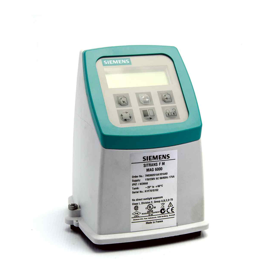
SITRANS F M MAG 5000/6000
Operating Instructions • 01/2010
SITRANS F
Related Manuals for Siemens SITRANS F M MAG 5000
Summary of Contents for Siemens SITRANS F M MAG 5000
-
Page 1
Electromagnetic Flowmeters SITRANS F M MAG 5000/6000 Operating Instructions • 01/2010 SITRANS F… -
Page 3
Introduction Safety notes Description SITRANS F Installing/Mounting Flowmeters SITRANS F M MAG 5000/6000 Connecting Commissioning Operating Instructions Service and maintenance Functions Alarm, error, and system messages Troubleshooting/FAQs Technical data Spare parts/Accessories Menu diagrams Appendix Electromagnetic flow transmitter designed for use with… -
Page 4
Note the following: WARNING Siemens products may only be used for the applications described in the catalog and in the relevant technical documentation. If products and components from other manufacturers are used, these must be recommended or approved by Siemens. Proper transport, storage, installation, assembly, commissioning, operation and maintenance are required to ensure that the products operate safely and without any problems. -
Page 5: Table Of Contents
Electrical connection ……………………34 Connection of add-on modules ………………..35 Commissioning ……………………….37 MAG 5000/6000 Blind……………………37 Local user interface……………………38 Menu structure ……………………..39 Changing password ……………………40 Changing basic settings…………………..40 Changing operator menu setup ………………..42 Changing language……………………43 SITRANS F M MAG 5000/6000 Operating Instructions, 01/2010, SFIDK.PS.026.G1.02…
-
Page 6
Overview MAG 5000/6000 ………………….73 Overview MAG 5000/6000 CT ………………..75 Change password ……………………76 Basic settings ……………………..77 Operator menu setup ……………………78 Language mode …………………….. 79 Current output ……………………..79 SITRANS F M MAG 5000/6000 Operating Instructions, 01/2010, SFIDK.PS.026.G1.02… -
Page 7
Reset mode — MAG 6000 SV …………………..86 A.19 Service mode ……………………..87 A.20 Product identity ……………………..88 A.21 HART module……………………..89 Appendix…………………………91 Factory settings……………………..91 Sensor dependent factory settings for MAG 5000/6000 Blind………….93 Approvals/certificates……………………94 B.3.1 Certificates ………………………94 Index………………………….. 95 SITRANS F M MAG 5000/6000 Operating Instructions, 01/2010, SFIDK.PS.026.G1.02… -
Page 8
Table of contents SITRANS F M MAG 5000/6000 Operating Instructions, 01/2010, SFIDK.PS.026.G1.02… -
Page 9: Introduction
It is the responsibility of the customer that the instructions and directions provided in the manual are read, understood and followed by the relevant personnel before installing the device. Items supplied • SITRANS F M MAG 5000/6000 transmitter • Calibration report • SITRANS F literature CD •…
-
Page 10: History
The contents of these instructions are regularly reviewed and corrections are included in subsequent editions. We welcome all suggestions for improvement. The following table shows the most important changes in the documentation compared to each previous edition. Edition Remarks First edition 01/2010 SITRANS F M MAG 5000/6000 Operating Instructions, 01/2010, SFIDK.PS.026.G1.02…
-
Page 11: Further Information
Product information on the Internet The Operating Instructions are available on the CD-ROM shipped with the device, and on the Internet on the Siemens homepage, where further information on the range of SITRANS F flowmeters may also be found: Product information on the internet (http://www.siemens.com/flowdocumentation)
-
Page 12
Introduction 1.4 Further Information SITRANS F M MAG 5000/6000 Operating Instructions, 01/2010, SFIDK.PS.026.G1.02… -
Page 13: Safety Notes
CE marked equipment The CE-mark symbolizes the compliance of the device with the following guidelines: ● EMC-guideline 89/336/EEC ● Low voltage guideline 73/23/EWG ● ATEX Directive 94/9/EG ● CT: (MI-001) Directive 2004/22/EC SITRANS F M MAG 5000/6000 Operating Instructions, 01/2010, SFIDK.PS.026.G1.02…
-
Page 14: Installation In Hazardous Location
● EN50281-1-2 is considered for installation in areas with combustible dust. ● When protective earth (PE) is connected, no potential difference between the protective earth (PE) and the potential equalization (PA) can exist, even during a fault condition. SITRANS F M MAG 5000/6000 Operating Instructions, 01/2010, SFIDK.PS.026.G1.02…
-
Page 15: Description
Description System components A SITRANS F M MAG 5000/6000 flowmeter system includes: ● Transmitter (type SITRANS F M MAG 5000/6000) ● Sensor (types: SITRANS F MAG 1100/1100F/3100/3100 P/5100 W) ● Communication module (optional) (types: HART, PROFIBUS PA/DP, MODBUS RTU RS 485, Foundation Fieldbus H1, Devicenet) ●…
-
Page 16: Features
Output module The output module converts flow data to analog, digital and relay outputs. The outputs are galvanically isolated and can be individually set to suit a particular application. SITRANS F M MAG 5000/6000 Operating Instructions, 01/2010, SFIDK.PS.026.G1.02…
-
Page 17: Mag 5000/Mag 6000 Versions
SV version (MAG 6000 only) This version is identical to the standard MAG 6000 transmitters except for the following additional functions: ● Zero point adjustment ● Adjustable excitation frequency up to 44 Hz SITRANS F M MAG 5000/6000 Operating Instructions, 01/2010, SFIDK.PS.026.G1.02…
-
Page 18
Description 3.5 MAG 5000/MAG 6000 versions SITRANS F M MAG 5000/6000 Operating Instructions, 01/2010, SFIDK.PS.026.G1.02… -
Page 19: Installing/Mounting
No further assembling is necessary. The transmitter can be installed either compact on the sensor or remote. Figure 4-1 Compact installation Figure 4-2 Remote installation CAUTION See Cable requirements (Page 68) before installing transmitter SITRANS F M MAG 5000/6000 Operating Instructions, 01/2010, SFIDK.PS.026.G1.02…
-
Page 20: Installation Conditions
Reading and operating the flowmeter is possible under almost any installation conditions because the display can be oriented in relation to the sensor. To ensure optimum flow measurement, attention should be paid to the following: Vibrations Figure 4-3 Avoid strong vibrations SITRANS F M MAG 5000/6000 Operating Instructions, 01/2010, SFIDK.PS.026.G1.02…
-
Page 21
Standard, blind and SV versions Figure 4-5 CT version Remote installation Cable length and type (as described in Cable requirements) must be used. For installation conditions for sensors, see respective sensor operating instructions. SITRANS F M MAG 5000/6000 Operating Instructions, 01/2010, SFIDK.PS.026.G1.02… -
Page 22: Mag 5000/6000 Compact
System will not register flow if black plugs are not connected to connection board 7. Fit supply and output cables through cable glands and connect to connection plate as shown in Electrical connection (Page 34). SITRANS F M MAG 5000/6000 Operating Instructions, 01/2010, SFIDK.PS.026.G1.02…
-
Page 23
11. Transmitter is ready to be powered up. CAUTION Exposing transmitter to direct sunlight may increase operating temperature above its specified limit, and decrease display visibility. A sunshield is available as accessory. SITRANS F M MAG 5000/6000 Operating Instructions, 01/2010, SFIDK.PS.026.G1.02… -
Page 24: Remote Installation
1. Remove terminal box lid. 2. Remove SENSORPROM unit from sensor terminal box and mount it in terminal box of ® wall mounting unit. 3. Fit M20 or ½» NPT cable glands for cables. SITRANS F M MAG 5000/6000 Operating Instructions, 01/2010, SFIDK.PS.026.G1.02…
-
Page 25
Unscreened cable ends must be kept as short as possible. Electrode cable and coil cable must be kept separate to prevent interference. 5. Tighten cable glands well to obtain optimum sealing. WARNING Mount terminal box lid before power up. SITRANS F M MAG 5000/6000 Operating Instructions, 01/2010, SFIDK.PS.026.G1.02… -
Page 26
2. Ensure that correct SENSORPROM memory unit is mounted in wall/pipe mounting unit. ® 3. Fit M20 or ½» NPT cable glands for cables from bottom or sides of terminal box. SITRANS F M MAG 5000/6000 Operating Instructions, 01/2010, SFIDK.PS.026.G1.02… -
Page 27
3. Tighten cable glands to obtain optimum sealing. CAUTION When remote mounted, power supply PE wire must be connected to PE terminal ( Coil cable shield must be connected to SHIELD terminal. SITRANS F M MAG 5000/6000 Operating Instructions, 01/2010, SFIDK.PS.026.G1.02… -
Page 28
5. Transmitter is ready to be powered up. CAUTION Exposing the transmitter to direct sunlight may increase the operating temperature above its specified limit, and decrease display visibility. A sun shield is available as accessory. SITRANS F M MAG 5000/6000 Operating Instructions, 01/2010, SFIDK.PS.026.G1.02… -
Page 29: Mag 5000/6000 Ct
Setting of primary operating parameters is blocked during normal operation. When key is mounted, access to all menu items is gained. When key is removed, primary settings are blocked in accordance with requirements in authorisation. SITRANS F M MAG 5000/6000 Operating Instructions, 01/2010, SFIDK.PS.026.G1.02…
-
Page 30: Seal Device
1. Seal connection plate to prevent access to SENSORPROM memory unit as shown ® below. 1 indicates sealing locations. 2. Drill through marked drilling holes in terminal box and transmitter/lid. Seal transmitter externally as shown below. SITRANS F M MAG 5000/6000 Operating Instructions, 01/2010, SFIDK.PS.026.G1.02…
-
Page 31: Turning Transmitter/Keypad
Terminal box can be rotated ±90° in order to optimize viewing angle of transmitter display/keypad 1. Unscrew the four screws in bottom of terminal box. 2. Turn terminal box to required position. 3. Retighten screws firmly. SITRANS F M MAG 5000/6000 Operating Instructions, 01/2010, SFIDK.PS.026.G1.02…
-
Page 32
Installing/Mounting 4.5 Turning transmitter/keypad Keypad 1. Remove outer frame using a screwdriver. 2. Loosen the four screws retaining keypad. 3. Withdraw keypad and turn it to required orientation. SITRANS F M MAG 5000/6000 Operating Instructions, 01/2010, SFIDK.PS.026.G1.02… -
Page 33
Installing/Mounting 4.5 Turning transmitter/keypad 4. Tighten the four screws until a mechanical stop is felt in order to obtain IP67 enclosure. 5. Snaplock outer frame onto keypad (click). SITRANS F M MAG 5000/6000 Operating Instructions, 01/2010, SFIDK.PS.026.G1.02… -
Page 34
Installing/Mounting 4.5 Turning transmitter/keypad SITRANS F M MAG 5000/6000 Operating Instructions, 01/2010, SFIDK.PS.026.G1.02… -
Page 35: Connecting
For field wiring installation: Ensure that the National Installation Code of the country in which the flowmeters are installed is met. Note National installation code Observe country specific installation directives for field wiring. SITRANS F M MAG 5000/6000 Operating Instructions, 01/2010, SFIDK.PS.026.G1.02…
-
Page 36: Electrical Connection
Terminals 81 and 84 are only to be connected if special electrode cable with double screening is used, e.g. when empty pipe function or long cables are used. Mains supply Mains supply 115 … 230 V AC from building installation Class II. SITRANS F M MAG 5000/6000 Operating Instructions, 01/2010, SFIDK.PS.026.G1.02…
-
Page 37: Connection Of Add-On Modules
91-97. For more information Refer to the relevant BUS communication Quick Start or Operating Instructions available at the SITRANS F literature CD or on the internet, at : www.siemens.com/flowdocumentation (www.siemens.com/flowdocumentation). SITRANS F M MAG 5000/6000 Operating Instructions, 01/2010, SFIDK.PS.026.G1.02…
-
Page 38
Connecting 5.2 Connection of add-on modules SITRANS F M MAG 5000/6000 Operating Instructions, 01/2010, SFIDK.PS.026.G1.02… -
Page 39: Commissioning
All changed data will be stored in SENSORPROM memory unit. ® 4. Remove standard transmitter and remount Blind transmitter. 5. Fasten screws holding transmitter. New settings stored in SENSORPROM memory unit will be uploaded in blind transmitter. ® SITRANS F M MAG 5000/6000 Operating Instructions, 01/2010, SFIDK.PS.026.G1.02…
-
Page 40: Local User Interface
Lock field Figure 6-1 Local User Interface Mode field symbols Communication mode Language mode Sensor characteristics Service mode Basic settings Reset mode Operator menu Output Operator-active Product identity External input Operator-inactive SITRANS F M MAG 5000/6000 Operating Instructions, 01/2010, SFIDK.PS.026.G1.02…
-
Page 41: Menu Structure
View mode is a read-only mode. The pre-selected settings can only be scanned. Setup mode is a read and write mode. The pre-selected settings can be scanned and changed. Access to the setup mode is password-protected. The factory set password is 1000. SITRANS F M MAG 5000/6000 Operating Instructions, 01/2010, SFIDK.PS.026.G1.02…
-
Page 42: Changing Password
This menu is only visible if chosen as external digital input. Totalizer Setting of unit and decimal point. Low flow cut-off Setting of a percentage of selected Q . This filters noise in installation reducing fluctuations in display and all outputs. SITRANS F M MAG 5000/6000 Operating Instructions, 01/2010, SFIDK.PS.026.G1.02…
-
Page 43
3. Use change key to move decimal point to requested position. Changing units 1. Use select key to position cursor below unit. 2. Press change key until requested unit is displayed. SITRANS F M MAG 5000/6000 Operating Instructions, 01/2010, SFIDK.PS.026.G1.02… -
Page 44: Changing Operator Menu Setup
3. Use select key to move cursor to symbol. 4. Press change key to select visible ( ) or hidden ( 5. Press lock/unlock key to confirm new setting. SITRANS F M MAG 5000/6000 Operating Instructions, 01/2010, SFIDK.PS.026.G1.02…
-
Page 45: Changing Language
5. Use change key to select desired language. 6. Press lock/unlock key to confirm new language. 7. Press top up key two times to exit setup mode. See language mode diagram (Page 79) SITRANS F M MAG 5000/6000 Operating Instructions, 01/2010, SFIDK.PS.026.G1.02…
-
Page 46
Commissioning 6.7 Changing language SITRANS F M MAG 5000/6000 Operating Instructions, 01/2010, SFIDK.PS.026.G1.02… -
Page 47: Service And Maintenance
It is a highly advanced instrument, which carries out the complex verification of the entire flowmeter system according to unique SIEMENS patented principles. The verification test is automated and the instrument easy to use, so no human error or influence will affect the verification.
-
Page 48: Technical Support
Sensor check list Check list for sensors are included in the respective sensor operating instructions. Technical support CAUTION Repair and service must be carried out by approved Siemens Flow Instruments personnel only. Note Siemens Flow Instrument defines sensors as non-repairable products.
-
Page 49
● Information about field service, repairs, spare parts and lots more under «Services.» Additional Support Please contact your local Siemens representative and offices if you have additional questions about the device Find your contact partner at: Local contact person (http://www.automation.siemens.com/partner) -
Page 50: Return Procedures
You can find the forms on the Internet and on the CD delivered with the device. Recalibration Siemens Flow Instruments offers to recalibrate the sensor. The following calibrations are offered as standard: ● Standard matched pair calibration ● Customer specified matched pair calibration (up to 10 points) ●…
-
Page 51: Functions
● Frequency (frequency output, max frequency, and time constant), see frequency menu diagram (Page 80). ● Error settings (level and number), see error level menu diagram (Page 80) and error number menu diagram (Page 80). SITRANS F M MAG 5000/6000 Operating Instructions, 01/2010, SFIDK.PS.026.G1.02…
-
Page 52: External Input
By applying 11 … 30 V DC to terminals 77 and 78, it is possible to perform: ● Batch control (start, stop, hold/continue) ● Reset totalizer ● Force/freeze output ● Q 2 (night) SITRANS F M MAG 5000/6000 Operating Instructions, 01/2010, SFIDK.PS.026.G1.02…
-
Page 53: Sensor Characteristics
® ● Suppress error P 40 (SENSORPROM not installed) ® ● Sensor size. ● Calibration factor. ● Correction factor. ● Excitation. See also sensor characteristics menu diagram (Page 84). SITRANS F M MAG 5000/6000 Operating Instructions, 01/2010, SFIDK.PS.026.G1.02…
-
Page 54: Reset Mode
4. Press lock/unlock key to enter reset menu. 5. Press forward key to reach zero adjust menu. 6. Press lock/unlock key to enter the menu. 7. Use change key to select «manual». SITRANS F M MAG 5000/6000 Operating Instructions, 01/2010, SFIDK.PS.026.G1.02…
-
Page 55: Service Mode
● When choosing hot water, changing the output settings is not allowed and the output setting menus are not shown in display. ● When choosing cold water or other liquids, all output settings can be changed. SITRANS F M MAG 5000/6000 Operating Instructions, 01/2010, SFIDK.PS.026.G1.02…
-
Page 56: Mag 6000 Sv
When this is done, the decrease in measuring accuracy can be kept below 1% o.r. A too high frequency for the sensor used will cause a coil current alarm indication. SITRANS F M MAG 5000/6000 Operating Instructions, 01/2010, SFIDK.PS.026.G1.02…
-
Page 57: Alarm, Error, And System Messages
Error text will indicate type of error (I, W, P or F), error number, and error text. Remedy text will inform operator of action to take to remove error. SITRANS F M MAG 5000/6000 Operating Instructions, 01/2010, SFIDK.PS.026.G1.02…
-
Page 58
The analog output turns to a 1 mA level when in the 4 … 20 mA mode. Operator menu Error pending and status log are as default enabled ( ) in the operator menu. SITRANS F M MAG 5000/6000 Operating Instructions, 01/2010, SFIDK.PS.026.G1.02… -
Page 59: List Of Error Numbers
P41 — Parameter range Switch off and on A parameter is out of range. The parameter could Active Active not be replaced by its default value. The error will disappear at the next power-on SITRANS F M MAG 5000/6000 Operating Instructions, 01/2010, SFIDK.PS.026.G1.02…
-
Page 60
It is not possible to read from the SENSORPROM Active Active ® unit anymore F70 — Coil current Check cables Coil excitation has failed Active Active F71 — Internal error Replace transmitter Internal convertion error in ASIC Active Active SITRANS F M MAG 5000/6000 Operating Instructions, 01/2010, SFIDK.PS.026.G1.02… -
Page 61: Troubleshooting/Faqs
MAG ® CT transmitter Defective SENSORPROM Replace SENSORPROM unit ® ® unit Wrong type of Replace SENSORPROM unit ® SENSORPROM unit ® Defective SENSORPROM Replace SENSORPROM unit ® ® unit SITRANS F M MAG 5000/6000 Operating Instructions, 01/2010, SFIDK.PS.026.G1.02…
-
Page 62
Change pulse width Measuring approx. Missing one electrode Check cables connection Loss of totalizer data Initializing error Reset totalizer manually ##### Signs in Totalizer roll over Reset totalizer or increase totalizer display unit SITRANS F M MAG 5000/6000 Operating Instructions, 01/2010, SFIDK.PS.026.G1.02… -
Page 63: Technical Data
0.1 … 30 s, adjustable (for batch: fixed at 0.1 Relay output Time constant Changeover relay, same as current output Load 42 V AC/2 A, 24 V DC/1 A Low flow cut off 0 … 9.9% of maximum flow SITRANS F M MAG 5000/6000 Operating Instructions, 01/2010, SFIDK.PS.026.G1.02…
-
Page 64
Hot water pattern approval: PTB and DANAK OIML R 75 (MAG 6000 CT) Other media than water (milk, beer etc.) pattern approval: PTB and DANAK OIML R 117 (MAG 6000 CT) SITRANS F M MAG 5000/6000 Operating Instructions, 01/2010, SFIDK.PS.026.G1.02… -
Page 65
MAG 5000 CT / MAG 6000 CT No communication modules approved Transmitter IP67/NEMA 4X/6 compact polyamide Weight: MAG 5000/6000: 0.75 kg (1.65 lbs) Transmitter IP67/NEMA 4X/6 wall-mounted polyamide Weight(transmitter and wall mounting bracket): 1.65 kg (3.64 lbs) SITRANS F M MAG 5000/6000 Operating Instructions, 01/2010, SFIDK.PS.026.G1.02… -
Page 66: Accuracy
< 0.1 m/s (0.3 ft/s) —> E: ±(0.25/v) % of measured value 12 [m/s] [ft/s] Figure 11-2 MAG 6000 with MAG 1100 (not PFA), MAG 1100 F (not PFA), MAG 5100 W, MAG 3100 and MAG 3100 P SITRANS F M MAG 5000/6000 Operating Instructions, 01/2010, SFIDK.PS.026.G1.02…
-
Page 67
< 0.005% of measuring value on 1% change Repeatability ± 0.1% of actual flow for V ≥ 0.5 m/s (1.5 ft/s) and conductivity ≥ 10 μS/cm Additions in the event of deviations from reference conditions SITRANS F M MAG 5000/6000 Operating Instructions, 01/2010, SFIDK.PS.026.G1.02… -
Page 68: Output Characteristics
0 … 20 mA 4 … 20 mA Frequency Pulse output Relay Power down Active Error relay No error Error Limit switch or direction switch Low flow Intermediate flow (Reverse flow) SITRANS F M MAG 5000/6000 Operating Instructions, 01/2010, SFIDK.PS.026.G1.02…
-
Page 69
Technical data 11.3 Output characteristics Output characteristics Bidirectional mode Unidirectional mode High flow High flow / (Forward flow) Low flow Batch on digital output Batch on relay Hold Batch SITRANS F M MAG 5000/6000 Operating Instructions, 01/2010, SFIDK.PS.026.G1.02… -
Page 70: Cable Data
Cable glands on sensor and M20x1.5 gland — Cable ø 5 … 13 mm (0.20 … 0.51 inches) transmitter ½ NPT gland — cable ø 5 … 9 mm (0.20 … 0.35 inches) SITRANS F M MAG 5000/6000 Operating Instructions, 01/2010, SFIDK.PS.026.G1.02…
-
Page 71: Spare Parts/Accessories
In order to ensure that the ordering data you are using is not outdated, the latest ordering data is always available on the Internet: Catalog process instrumentation (http://www.siemens.com/processinstrumentation/catalogs) 12.2 Accessories Description Wall mounting unit Display protection lid Communication modules for MAG 6000 SITRANS F M MAG 5000/6000 Operating Instructions, 01/2010, SFIDK.PS.026.G1.02…
-
Page 72: Spare Parts
Spare parts/Accessories 12.3 Spare parts 12.3 Spare parts Description Connection plate SENSORPROM memory unit ® Display unit Communication modules for MAG 6000 SITRANS F M MAG 5000/6000 Operating Instructions, 01/2010, SFIDK.PS.026.G1.02…
-
Page 73: Sun Shield
Spare parts/Accessories 12.4 Sun shield 12.4 Sun shield Description Sun shield SITRANS F M MAG 5000/6000 Operating Instructions, 01/2010, SFIDK.PS.026.G1.02…
-
Page 74
Spare parts/Accessories 12.4 Sun shield SITRANS F M MAG 5000/6000 Operating Instructions, 01/2010, SFIDK.PS.026.G1.02… -
Page 75: Menu Diagrams
Menu diagrams Overview MAG 5000/6000 Figure A-1 Overview MAG 5000 and MAG 6000 (part 1) SITRANS F M MAG 5000/6000 Operating Instructions, 01/2010, SFIDK.PS.026.G1.02…
-
Page 76
Menu diagrams A.1 Overview MAG 5000/6000 MAG 6000 I only Add-on module Factory-set password: 1000 Not available when batch Only available when batch SITRANS F M MAG 5000/6000 Operating Instructions, 01/2010, SFIDK.PS.026.G1.02… -
Page 77: Overview Mag 5000/6000 Ct
Overview MAG 5000 CT and MAG 6000 CT (part 1) Factory-set password: 1000 Not visible when CT mode is «Hot water» Figure A-3 Overview MAG 5000 CT and MAG 6000 CT (part 2) SITRANS F M MAG 5000/6000 Operating Instructions, 01/2010, SFIDK.PS.026.G1.02…
-
Page 78: Change Password
Menu diagrams A.3 Change password Note Sealing Menus marked with gray are locked when transmitter is sealed. Change password SITRANS F M MAG 5000/6000 Operating Instructions, 01/2010, SFIDK.PS.026.G1.02…
-
Page 79: Basic Settings
Menu diagrams A.4 Basic settings Basic settings SITRANS F M MAG 5000/6000 Operating Instructions, 01/2010, SFIDK.PS.026.G1.02…
-
Page 80: Operator Menu Setup
Menu diagrams A.5 Operator menu setup Operator menu setup SITRANS F M MAG 5000/6000 Operating Instructions, 01/2010, SFIDK.PS.026.G1.02…
-
Page 81: Language Mode
Menu diagrams A.6 Language mode Language mode Current output Current output Current output Current output Current output Time const. Unidirectional Unidirectional Bidirectional Alarm Digital output — pulse Not at batch SITRANS F M MAG 5000/6000 Operating Instructions, 01/2010, SFIDK.PS.026.G1.02…
-
Page 82: Digital Output — Frequency
Menu diagrams A.9 Digital output — frequency Digital output — frequency A.10 Error level A.11 Error number SITRANS F M MAG 5000/6000 Operating Instructions, 01/2010, SFIDK.PS.026.G1.02…
-
Page 83: Direction/Limit
Menu diagrams A.12 Direction/limit A.12 Direction/limit SITRANS F M MAG 5000/6000 Operating Instructions, 01/2010, SFIDK.PS.026.G1.02…
-
Page 84: Batch
A.13 Batch A.13 Batch A.14 Cleaning Note Relay outputs If cleaning unit is installed, relay outputs must always be used to operate cleaning. Relay outputs cannot be used for other purposes SITRANS F M MAG 5000/6000 Operating Instructions, 01/2010, SFIDK.PS.026.G1.02…
-
Page 85: External Input
Menu diagrams A.15 External input A.15 External input SITRANS F M MAG 5000/6000 Operating Instructions, 01/2010, SFIDK.PS.026.G1.02…
-
Page 86: Sensor Characteristics
Menu diagrams A.16 Sensor characteristics A.16 Sensor characteristics Note MAG 6000 SV The frequency can be set to 44 Hz in the MAG 6000 SV transmitter only. SITRANS F M MAG 5000/6000 Operating Instructions, 01/2010, SFIDK.PS.026.G1.02…
-
Page 87: Reset Mode
Menu diagrams A.17 Reset mode A.17 Reset mode SITRANS F M MAG 5000/6000 Operating Instructions, 01/2010, SFIDK.PS.026.G1.02…
-
Page 88: Reset Mode — Mag 6000 Sv
Menu diagrams A.18 Reset mode — MAG 6000 SV A.18 Reset mode — MAG 6000 SV SITRANS F M MAG 5000/6000 Operating Instructions, 01/2010, SFIDK.PS.026.G1.02…
-
Page 89: Service Mode
Menu diagrams A.19 Service mode A.19 Service mode Standard If digital input is set to frequency Not when relay is set to batch SITRANS F M MAG 5000/6000 Operating Instructions, 01/2010, SFIDK.PS.026.G1.02…
-
Page 90: Product Identity
Menu diagrams A.20 Product identity A.20 Product identity SITRANS F M MAG 5000/6000 Operating Instructions, 01/2010, SFIDK.PS.026.G1.02…
-
Page 91: Hart Module
Menu diagrams A.21 HART module A.21 HART module SITRANS F M MAG 5000/6000 Operating Instructions, 01/2010, SFIDK.PS.026.G1.02…
-
Page 92
Menu diagrams A.21 HART module SITRANS F M MAG 5000/6000 Operating Instructions, 01/2010, SFIDK.PS.026.G1.02… -
Page 93: Appendix
Direction/limit 1 setpoint, 2 setpoints Direction/lim switch it (Page 81) Setpoints 0 … 100% -100 … +100% • Hysteresis 0.0 … 100% • Batch Batch (Page 82) Batch quantity Dimension-dependent • SITRANS F M MAG 5000/6000 Operating Instructions, 01/2010, SFIDK.PS.026.G1.02…
-
Page 94
Totalizer 2, Totalizer 1 reset, Totalizer 2 reset, Batch start/paused/stop, Batch cycle counter, Batch cycle counter reset, Sensor size, Sensor type, Error pending, Status log, Tag No. : Available on MAG 6000 only. SITRANS F M MAG 5000/6000 Operating Instructions, 01/2010, SFIDK.PS.026.G1.02… -
Page 95: Sensor Dependent Factory Settings For Mag 5000/6000 Blind
1000 US G DN 1800 40 000 m 10 m 176 115 US GPM 1000 US G DN 2000 45 000 m 10 m 198 129 US GPM 1000 US G SITRANS F M MAG 5000/6000 Operating Instructions, 01/2010, SFIDK.PS.026.G1.02…
-
Page 96: Approvals/Certificates
Approvals/certificates B.3.1 Certificates All certificates are posted on the Internet. Additionally, the CE Declaration of Conformity as well as ATEX approvals are available on the Sitrans F literature CD-ROM. Certificates (http://support.automation.siemens.com/WW/view/en/10806951/134200) SITRANS F M MAG 5000/6000 Operating Instructions, 01/2010, SFIDK.PS.026.G1.02…
-
Page 97: Index
Safety notes, 11 Service, 46 Electrical connection, 35 Support, 46 System components, 13 Hotline, 46 Wire insulation, 33 Internet Contact person, 9, 47 Flowdocumentation, 9 Support, 46 Introduction, 7 Laws and directives, 11 SITRANS F M MAG 5000/6000 Operating Instructions, 01/2010, SFIDK.PS.026.G1.02…
-
Page 98
For more information www.siemens.com/flow A5E02338368-01 Siemens Flow Instruments A/S Subject to change without prior notice Nordborgvej 81 Order No.: A5E02338368-01 DK-6430 Nordborg Copyright Siemens AG 01.2010 All rights reserved www.siemens.com/processautomation…
(Ocr-Read Summary of Contents of some pages of the Siemens MAG 5000 Document (Main Content), UPD: 10 July 2023)
-
41, Commissioning 6.3 Menu structure SITRANS F M MAG 5000/6000 Operating Instructions, 01/2010, SFIDK.PS.026.G1.02 39 Lock field symbols Ready for change Access to submenu Value locked RESET MODE: Zero setting of totalizers and initialization of setting Keypad The keypad is used to set the flowmeter. The keys function as follows: TOP UP KEY This key (when held for 2 sec.) is used to switch between operator menu and setup menu. In transmitter setup m…
-
57, SITRANS F M MAG 5000/6000 Operating Instructions, 01/2010, SFIDK.PS.026.G1.02 55 Alarm, error, and system messages 9 9.1 Diagnostics Error system Transmitter system is equipped with an error and status log system with 4 groups of information. (I) Information — system will continue to measure as normal, relay and current outputs will not be affected. (W) Warning — system will continue to measure, but an event that may cause a system malfunction and require operator attention h…
-
68, Technical data 11.3 Output characteristics SITRANS F M MAG 5000/6000 66 Operating Instructions, 01/2010, SFIDK.PS.026.G1.02 11.3 Output characteristics Output characteristics Bidirectional mode Unidirectional mode 0 … 20 mA 4 … 20 mA Frequency Pulse output Relay Power down Active Error relay No error Error 83G1082a.10.10.02 83G1082b.10.10.02 Limit switch or direction switch …
-
50, Service and maintenance 7.3 Return procedures SITRANS F M MAG 5000/6000 48 Operating Instructions, 01/2010, SFIDK.PS.026.G1.02 7.3 Return procedures Enclose the delivery note, the cover note for return delivery together with the declaration of decontamination form on the outside of the package in a well-fastened clear document pouch. Required forms ● Delivery Note ● Cover Note for Ret…
-
3, 1 Introduction Safety notes 2 Description 3 Installing/Mounting 4 Connecting 5 Commissioning 6 Service and maintenance 7 Functions 8 Alarm, error, and system messages 9 Troubleshooting/FAQs 10 Technical data 11 Spare parts/Accessories 12 Menu diagrams A Appendix B SITRANS F Flowmeters SITRANS F M MAG 5000/6000 Operating Instructions Electromagnetic flow transmitter designed for use with flow sensor typ…
-
79, Menu diagrams A.4 Basic settings SITRANS F M MAG 5000/6000 Operating Instructions, 01/2010, SFIDK.PS.026.G1.02 77 A.4 Basic settings %DVLF VHWWLQJV 0DLQ IUHTXHQF\ )ORZ GLUHFWLRQ 3RVLWLYH 3RVLWLYH 1HJDWLYH 4 PD[ 4 PD[ QLJKW 7RWDOL]HU 7RWDOL]HU 7RWDOL]HU 7RWDOL]HU XQLW 7RWDOL]HU XQLW 7RWDOL]HU )RUZDUG )RUZDUG 5HYHUVH 1HW 7RWDOL]HU 5HYHUVH )RUZDUG 5HYHUVH 1HW (PSW\ SLSH FXWRII 2II 2II 2Q /R…
-
6, Table of contents SITRANS F M MAG 5000/6000 4 Operating Instructions, 01/2010, SFIDK.PS.026.G1.02 7 Service and maintenance ………………………………………………………………………………………………………… 45 7.1 Transmitter check list …………………………………………………………………………………………………… 45 7.2 Technical support…………………………..…
-
51, Siemens MAG 5000 SITRANS F M MAG 5000/6000 Operating Instructions, 01/2010, SFIDK.PS.026.G1.02 49 Functions 8 This chapter describes the various menus of the transmitter in details. The menu diagrams are shown in appendix menu diagrams (Page 73). 8.1 Output settings Three outputs are available: ● Current output (range and time constant); terminals 31 and 32. ● Digital output (pulse, frequency, error…
-
36, Connecting 5.1 Electrical connection SITRANS F M MAG 5000/6000 34 Operating Instructions, 01/2010, SFIDK.PS.026.G1.02 5.1 Electrical connection 5HOD\ RXWSXW ‘LJLWDO LQSXW 3/&’LJLWDO LQSXW $FWLYH RXWSXW 3RZHUHG IURP FRQYHUWHU &RPPRQ 9[ 9 PD[ P$ 5HOD\ ,QSXW 9 ‘& 9 $& &RLO FDEOH �…
-
81, Menu diagrams A.6 Language mode SITRANS F M MAG 5000/6000 Operating Instructions, 01/2010, SFIDK.PS.026.G1.02 79 A.6 Language mode /DQJXDJH PRGH /DQJXDJH (QJOLVK (QJOLVK ‘HXWVFK )UDQFDLV ‘DQVN 6YHQVND 6XRPHNVL 5XVVLDQ (VSD³RO ,WDOLDQR 3RUWXJX¬V 3ROVNL A.7 Current output Current output O Current output Time const. Current output Current output Unidirectional Alarm Unidirectional Bidirectional On O A.8 Digital…
-
91, Siemens MAG 5000 Menu diagrams A.21 HART module SITRANS F M MAG 5000/6000 Operating Instructions, 01/2010, SFIDK.PS.026.G1.02 89 A.21 HART module +$57 PRGXOH +$57 VKRUW DGGUHVV 7$* QDPH ‘HVFULSWLRQ ‘DWH +$57 6: YHUVLRQ
… -
31, Installing/Mounting 4.5 Turning transmitter/keypad SITRANS F M MAG 5000/6000 Operating Instructions, 01/2010, SFIDK.PS.026.G1.02 29 4.5 Turning transmitter/keypad It is possible to alter the standard assembly, e.g. to turn transmitter or keypad. Transmitter Figure 4-9 Transmitter can be mounted with its front in either direction indicated by the arrows without turning terminal box Figu…
-
11, Introduction 1.4 Further Information SITRANS F M MAG 5000/6000 Operating Instructions, 01/2010, SFIDK.PS.026.G1.02 9 1.4 Further Information The contents of these Operating Instructions shall not become part of or modify any prior or existing agreement, commitment or legal relationship. All obligations on the part of Siemens AG are contained in the respective sales contract which also contains the complete and solely applic…
-
35, SITRANS F M MAG 5000/6000 Operating Instructions, 01/2010, SFIDK.PS.026.G1.02 33 Connecting 5 WARNING Mains supply from building installation Class II A switch or circuit breaker (Max. 15 A) must be installed in close proximity to the equipment and within easy reach of the operator. It must be marked as the disconnecting device for the equipment. WARNING Protective conductor terminal The required cable is min. AGW16 or 1.5 Cu. WARNING Wire insulation The insula…
-
63, Siemens MAG 5000 SITRANS F M MAG 5000/6000 Operating Instructions, 01/2010, SFIDK.PS.026.G1.02 61 Technical data 11 11.1 Technical specifications Mode of operation and design Measuring principle Electromagnetic with pulsed constant field Empty pipe Detection of empty pipe (special cable required in remote mounted installation) Excitation frequency Depends on sensor size Electrode input …
-
92, Menu diagrams A.21 HART module SITRANS F M MAG 5000/6000 90 Operating Instructions, 01/2010, SFIDK.PS.026.G1.02
…
Table of Contents for Siemens MAG 5000:
-
Menu diagrams A.20 Change password 89 Note Sealing Menus marked with gray are locked when transmitter is sealed. A.20 Change password www.eltra-trade.com [email protected] +421 552 601 099
-
www.eltra-trade.com [email protected] +421 552 601 099 MAG 5000 is a series of transmitters from Siemens with a micropro- cessor, which is designed to work in electromagnetic flowmeters. MAGFLO 5000 electronic converters have the following features: — SENSORPROM technology — Graphic display available — Dosage function — Error log — Extensive communication options — Keyboard — Several supported languages Siemens Sitrans MAG 5000 is a universal transmitter for working in all the company’s magn
-
Introduction 1.4 Further Information 10 www.eltra-trade.com [email protected] +421 552 601 099
-
Commissioning 6.6 Changing operator menu setup 45 Changing decimal point position 1. Enter the respective totalizer menu. 2. Use select key to position cursor below decimal point. 3. Use change key to move decimal point to requested position. Changing units 1. Use select key to position cursor below unit. 2. Press change key until requested unit is displayed. 6.6 Changing operator menu setup In the operator menu the menus required for daily operation of the flowmeter are shown. It is po
-
11 2 Safety notes 2 CAUTION Correct, reliable operation of the product requires proper transport, storage, positioning and assembly as well as careful operation and maintenance. Only qualified personnel should install or operate this instrument. Note Alterations to the product, including opening or improper repairs of the product, are not permitted. If this requirement is not observed, the CE mark and the manufacturer’s warranty will expire.
-
19 4 Installing/Mounting 4 4.1 Introduction ● SITRANS F flowmeters are suitable for indoor and outdoor installations. WARNING Installation in hazardous location Special requirements apply to the location and interconnection of sensor and transmitter. See «Installation in hazardous area» This chapter describes how to install the flowmeter in the compact version as well as in the remote version. The transmitter is delivered ready for mounting on the sensor. The transmitter is delivered with a compr
-
Installing/Mounting 4.6 Turning transmitter/keypad 33 Keypad 1. Remove outer frame using a screwdriver. 2. Loosen the four screws retaining keypad. 3. Withdraw keypad and turn it to required orientation. www.eltra-trade.com [email protected] +421 552 601 099
-
Factory settings B.3 60 Hz Dimension dependent 94 DN Q max* Factory settting MAG 5100 W (Order no. 7ME6520) MAG 1100, MAG 1100 F, 5100 W (Order no. 7ME6580) MAG 3100, 3100 P unit mm (inch) min. max. min. max. 400 (16) 1800 113.0974 4523.893 113.0974 4523.893 m 3 /h 450 (18) 2000 143.1389 5725.552 143.1389 5725.552 m 3 /h 500 (20) 3000 176.7146 7068.5
-
Factory settings B.2 50 Hz Dimension dependent 93 Menu item Parameter Factory settings Options More info Sensor characteristics Correction factor 1 0.85 … 2.00 Sensor characteristi cs (Page 81) Language Language English English, German, French, Danish, Swedish, Finnish, Spanish, Russian, Italian, Portuguese, Polish Changing language (Page 46) Operator menu Primary field Flow rate Flow rate, Tota
-
Technical data 11.4 Cable data 71 Batch on relay output Unidirectional mode (forward flow only) Hold Batch 11.4 Cable data Description Cable for standard electrode or coil Electrode cable, double shielded Cable kit with standard coil cable and electrode cable double shielded (also available as low noise cable for MAG 1100 sensor ) Technical data Standard electrode cable (electrode/coil) S
-
Installing/Mounting 4.4 Remote installation 25 4. Fit and connect electrode (1) and coil (2) cables as shown in Electrical connection (Page 36). Note Unscreened cable ends must be kept as short as possible. Electrode cable and coil cable must be kept separate to prevent interference. 5. Tighten cable glands well to obtain optimum sealing. WARNING Mount terminal box lid before power u
-
Connecting 5.1 Electrical connection 36 5.1 Electrical connection Figure 5-1 Wiring diagram www.eltra-trade.com [email protected] +421 552 601 099
Questions, Opinions and Exploitation Impressions:
You can ask a question, express your opinion or share our experience of Siemens MAG 5000 device using right now.
| Document’s Content and Additional Information | Share Manual |
|---|---|
|
Siemens MAG 5000 Operating instructions manual
Pages Preview: Document Transcription:
See Details |
|
|
Siemens MAG 5000 Handbook
Pages Preview: Document Transcription:
See Details |
|
|
Siemens MAG 5000 Instructions manual
Pages Preview: Document Transcription:
See Details |
|
|
Siemens MAG 5000 Manual
Pages Preview: Document Transcription:
See Details |
|
|
Siemens MAG 5000 Operating instructions manual
Pages Preview: Document Transcription:
See Details |
|
|
Siemens MAG 5000 Operating instructions manual
Pages Preview: Document Transcription: See Details |
|
|
Siemens MAG 5000 Operating instructions manual
Pages Preview: Document Transcription:
See Details |
|
|
Siemens MAG 5000 Quick start manual
Pages Preview: Document Transcription:
See Details |


SITRANS F
Flowmeters
SITRANS F M MAG 5000/6000
Operating Instructions
Electromagnetic flow transmitter designed for use with
flow sensor types
MAG 1100/1100 F/3100/3100 P/5100 W
Compact and remote installation
01/2010
SFIDK.PS.026.G1.02
Introduction
Safety notes
Description
Installing/Mounting
Connecting
Commissioning
Service and maintenance
Functions
Alarm, error, and system
messages
Troubleshooting/FAQs
Technical data
Spare parts/Accessories
Menu diagrams
Appendix
1
2
3
4
5
6
7
8
9
10
11
12
A
B