- Manuals
- Brands
- RayTek Manuals
- Accessories
- MI3
- Operating instructions manual
-
Contents
-
Table of Contents
-
Bookmarks
Quick Links
MI3
Miniature Infrared Sensor
Operating Instructions
Rev. G Nov/2015
55201
Related Manuals for RayTek MI3
Summary of Contents for RayTek MI3
-
Page 1: Operating Instructions
Miniature Infrared Sensor Operating Instructions Rev. G Nov/2015 55201…
-
Page 3
Thank you for purchasing this Raytek product. Register today at www.raytek.com/register to receive the latest updates, enhancements and software upgrades! © Raytek Corporation. Raytek and the Raytek Logo are registered trademarks of Raytek Corporation. All rights reserved. Specifications subject to change without notice. -
Page 4
ARRANTY The manufacturer warrants this product to be free from defects in material and workmanship under normal use and service for the period of two years from date of purchase, except as hereinafter provided. This warranty extends only to the original purchaser (a purchase from the manufacturer or a licensed distributor of the manufacturer is an original purchase). -
Page 5: Table Of Contents
Content CONTENT …………………………..5 1 SAFETY INSTRUCTIONS ……………………..10 2 DESCRIPTION …………………………13 2.1 O ··························································································································· 14 VERVIEW OXES 3 TECHNICAL DATA ……………………….15 3.1 M ················································································································· 15 EASUREMENT PECIFICATION 3.1.1 Sensing Heads ……………………….. 15 3.1.2 Comm Box ……………………….16 3.1.2.1 Comm Box (metal) ………………………..
-
Page 6
5.4 W ··································································································································· 29 IRING ERMINAL 5.4.1 Comm Box (metal) ……………………..29 5.4.2 Comm Box (DIN 3TE) ……………………30 5.4.3 Comm Box (DIN 4 TE) ……………………31 5.4.4 Comm Box (DIN 6 TE) ……………………32 5.4.5 EMI Resistance for Comm Box (DIN) ………………..35 5.5 P ····························································································································… -
Page 7
9.2.4 Mains Supply ……………………….61 9.2.5 Ex Power Supply 115MI3ACIS / 230MI3ACIS …………….63 10 ACCESSORIES ………………………… 64 10.1 A ) ···················································································································· 64 CCESSORIES ALL MODELS 10.1.1 Multi-Channel Box ……………………… 64 10.1.2 USB/RS485 Adapter ……………………. 67 10.2 A (LT, G5 H ) ·················································································································… -
Page 8: Data Logging
··················································································································································· 103 IRING 16.1.1 Comm Box (metal) …………………….. 103 16.1.2 Comm Box (DIN) ……………………… 103 16.2 A ··········································································································································· 104 DDRESSING 16.2.1 MI3 …………………………104 16.2.2 PC Network Adapter ……………………105 16.3 ASCII P ··························································································································· 106 ROGRAMMING 16.4 ·········································································································································· 107 HTTP ERVER 16.4.1 Data Logging ……………………..
-
Page 9: Lock Mode
18.7.4 Factory default values ……………………121 18.7.5 Lock Mode ……………………….121 18.7.6 Mode Setting for the Digital Input FTC3 ………………121 18.7.7 Ambient Background Temperature Compensation …………….. 121 18.8 C ······································································································································· 121 OMMAND 18.8.1 ASCII Commands for Ethernet and Profinet ……………… 127 19 APPENDIX …………………………
-
Page 10: Safety Instructions
Safety Instructions 1 Safety Instructions This document contains important information, which should be kept at all times with the instrument during its operational life. Other users of this instrument should be given these instructions with the instrument. Eventual updates to this information must be added to the original document. The instrument should only be operated by trained personnel in accordance with these instructions and local safety regulations.
-
Page 11
Safety Instructions Safety Symbols AC (Alternating Current) DC (Direct Current) Risk of danger. Important information. See manual. Hazardous voltage. Risk of electrical shock. Helpful information regarding the optimal use of the instrument. Earth ground Protective ground Fuse Normally-open (NO) relay Normally-closed (NC) relay Switch or relay contact DC power supply… -
Page 12
Safety Instructions The instrument can be equipped with a Class 2 laser. Class 2 lasers shine only within the visible spectrum at an intensity of 1 mW. Looking directly into the laser beam can produce a slight, temporary blinding effect, but does not result in physical injury or damage to the eyes, even when the beam is magnified by optical aids. -
Page 13: Description
Description 2 Description The MI3 sensor series is the next generation of the well-established “MI class” sensor platform. It will be capable of covering a broad range of applications. The MI3 sensor series introduces various network communications, an externally accessible user interface, improved temperature measurement specifications and capabilities at an economic price.
-
Page 14: Overview Comm Boxe
Description 2.1 Overview Comm Boxes MI3COMM MI3MCOMMN MI3MCOMM MI3MCOMM… metal box DIN 3TE DIN 4TE DIN 6TE Part number MI3COMM… MI3MCOMMN MI3MCOMM MI3MCOMM… Spectral Heads LT, G5, 1M, 2M LT, G5, 1M, 2M LT, G5, 1M, 2M LT, G5, 1M, 2M Head Support by firmware 8 heads…
-
Page 15: Technical Data
Technical Data 3 Technical Data 3.1 Measurement Specification 3.1.1 Sensing Heads Temperature Range LTS02, LTS10, LTH10 -40 to 600°C (-40 to 1112°F) LTS20, LTF, LTH20 0 to 1000°C (32 to 1832°F) 250 to 1650°C (482 to 3002°F) 250 to 1400°C (482 to 2552°F) 500 to 1800°C (932 to 3272°F) Spectral Response 8 to 14 µm…
-
Page 16: Comm Box
Technical Data 3.1.2 Comm Box Accuracy mA/V output ± 1°C (corresponds to ± 0.015 mA for the current output at 0-20 mA or ± 0.015 mA for the current output at 4-20 mA or 4 mV for the voltage output at 0-5 V or 8 mV for the voltage output at 0-10 V) TC output ±…
-
Page 17: O Ptical C Harts
Technical Data 3.2 Optical Charts Figure 1: Spot Size Charts Rev. G Nov/2015…
-
Page 18: E Lectrical S Pecification
Technical Data 3.3 Electrical Specification For an overview to the capabilities of the communication boxes, see section 2.1 Overview Comm Boxes, page 14. 3.3.1 Comm Box, all models Voltage Supply 8 to 32 VDC Power Consumption max. 6 W Alarm Output 1 potential-free relay output, 48 V / 300 mA Relay with wear-free contacts (solid state relay) for target temperature or head ambient temperature, electrically isolated from power supply…
-
Page 19: E Nvironmental S Pecification
Technical Data 3.4 Environmental Specification 3.4.1 Sensing Head Ambient Temperature LT, G5 -10 to 120°C (14 to 248°F) -10 to 180°C (14 to 356°F) 1M, 2M 0 to 120°C (32 to 248°F) Laser (1M, 2M) automatic switch off at 65°C (149°F) Storage Temperature -20 to 180°C (-4 to 356°F) all other models…
-
Page 20: Comm Box (Din)
Technical Data Electromagnetic Compatibility Applies to use in Korea only. Class A Equipment (Industrial Broadcasting & Communication Equipment) This product meets requirements for industrial (Class A) electromagnetic wave equipment and the seller or user should take notice of it. This equipment is intended for use in business environments and is not to be used in homes.
-
Page 21: D Imensions
Technical Data 3.5 Dimensions 3.5.1 Sensing Head LT, G5 Standard cable length 1 m (3 ft.) Ø 5 mm (0.2 in) Figure 2: Dimensions of LT, G5 Sensing Heads 3.5.2 Sensing Head LTH Figure 3: Dimensions of LTH Sensing Head with separated Electronics 3.5.3 Sensing Head 1M, 2M Standard cable length 1 m (3 ft)
-
Page 22: Scope Of Delivery
Technical Data Figure 5: Dimensions of Communication Box 3.5.5 Comm Box (DIN) The boxes come in a standard DIN rail size in accordance to EN 50022-35×7.5 (DIN 43880). Width MI3MCOMMN MI3MCOMM MI3MCOMM… DIN 3TE: DIN 4TE: DIN 6TE: 53.6 mm (2.1 in) 71.6 mm (2.8 in) 107.6 mm (4.2 in) Figure 6: Dimensions for Comm Boxes (DIN)
-
Page 23: Comm Box
Technical Data 3.6.2 Comm Box Communication box for Comm Box (DIN) only — XXXMI3MCOMMSET: ferrite cores (4 pcs), shield tapes (4 pcs) Software DVD Quickstart guide Rev. G Nov/2015…
-
Page 24: Basics
Basics 4 Basics 4.1 Measurement of Infrared Temperature All surfaces emit infrared radiation. The intensity of this infrared radiation changes according to the temperature of the object. Depending on the material and surface properties, the emitted radiation lies in a wavelength spectrum of approximately 1 to 20 µm. The intensity of the infrared radiation (heat radiation) is dependent on the material.
-
Page 25
Comm Box, or power. Please note that: The metal housings of the sensing head and the MI3 communication box are electrically connected to the shield of the head cable. All inputs and outputs (except the alarm output and the outputs of the Comm Box (DIN 6TE, analog)) use the same ground and are electrically connected to the power supply. -
Page 26: Installation
Installation 5 Installation 5.1 Positioning Sensor location depends on the application. Before deciding on a location, you need to be aware of the ambient temperature of the location, the atmospheric quality of the location, and the possible electromagnetic interference in that location. If you plan to use air purging, you need to have an air connection available.
-
Page 27: Comm Box (Din)
Installation Comm Box Power supply, (RAYMI3COMM) 2 analog Head 1 outputs, (RAYMI3…) 3 inputs Fieldbus Figure 11: Single Head Configuration with Comm Box To increase the number of supported sensing heads, you can use a dedicated accessory, see section 10.1.1 Multi-Channel Box, page 64.
-
Page 28: Comm Box (Metal)
The total sensing head cable length for all networked sensing heads must not exceed 30 m (98 ft) for MI3 and 2×30 m (2×98 ft) for MI3M! Do not add a third party cable to extend the length of the sensing head cable! 5.3.1 Comm Box (metal)
-
Page 29: Comm Box (Din)
Installation 5.3.2 Comm Box (DIN) The wiring of the sensing head cable is color coded, see section 5.4.3 Comm Box (DIN 4 TE), page 31. 5.4 Wiring, Terminal You need to connect the power supply and possibly the signal input/output wires. Use only cable with outside diameter from 4 to 6 mm (0.16 to 0.24 in), wire size: 0.14 to 0.75 mm²…
-
Page 30: Comm Box (Din 3Te)
Installation 5.4.2 Comm Box (DIN 3TE) Sensing Heads USB Connector, Mini-B Figure 15: Terminal Wiring for the Comm Box DIN 3TE Rev. G Nov/2015…
-
Page 31: Comm Box (Din 4 Te)
Installation 5.4.3 Comm Box (DIN 4 TE) Sensing Heads Termination USB Connector, Mini-B Figure 16: Terminal Wiring for the Comm Box DIN 4 TE Rev. G Nov/2015…
-
Page 32: Comm Box (Din 6 Te)
Installation 5.4.4 Comm Box (DIN 6 TE) Sensing Heads Wiring Profibus or Modbus USB Connector, Mini-B Figure 17: Terminal Wiring for the Comm Box DIN 6 TE for Profibus and Modbus Rev. G Nov/2015…
-
Page 33
Installation Sensing Heads USB Connector, Mini-B RJ45 connector Profinet or Ethernet Figure 18: Terminal Wiring for the Comm Box DIN 6 TE for Profinet and Modbus Rev. G Nov/2015… -
Page 34
Installation Sensing Heads see section Analog Outputs OUT1 — OUT4, page 41. Analog Outputs USB Connector, Mini-B Figure 19: Terminal Wiring for the Comm Box DIN 6 TE, analog Rev. G Nov/2015… -
Page 35: Emi Resistance For Comm Box (Din)
Installation 5.4.5 EMI Resistance for Comm Box (DIN) To maintain EMI compliance to CE standards the attached Ferrite cores need to be placed on all wires! Make sure that the cable shields will be connected to the terminal pin <Shield>! self-adhesive shield tape to wrap round the cable Shield wire connected to…
-
Page 36: Power On Procedure
Installation 5.5 Power On Procedure To power the system, the following procedures are required. 5.5.1 One Head System Disconnect power to the box. Connect the wires for the head to the box terminal. Power the box. The box now assigns address 1 to the head. 5.5.2 Multiple Heads –…
-
Page 37
Installation 5.6 USB The USB interface comes with each box (USB connector, Mini-B). Connect a single unit to a USB computer port by using an appropriate USB cable. USB connector, type Mini-B The computer’s USB port Figure 21: USB Connection via the Comm Box (metal) The computer’s USB port Figure 22: USB Connection via the Comm Box (DIN Rail) Rev. -
Page 38
Installation Consider the following sequence for the installation: Disconnect/reconnect the USB interface cable to the computer! Ignore the Windows Wizard <Found New Hardware>! Navigate manually to the dedicated USB driver <RaytekMIcomport.inf> on the support media and execute it. It is strongly recommended to check the correct driver installation under the Windows Operating System <Start>… -
Page 39: F Ieldbus
Installation 5.7 Fieldbus A simultaneous communication via USB and fieldbus is not allowed! 5.7.1 Addressing Each slave in the network must have a unique address and must run at the same baud rate! For setting the fieldbus configurations through the control panel, see section 8.3 <Box Setup>…
-
Page 40: Outputs
Outputs 6 Outputs For the outputs the following groupings (setups) are possible: Output Setup 1 Setup 2 Setup 3 Setup 4 Setup 5 OUT1 head temperature head temperature object temperature object temperature OUT2 object temperature object temperature object temperature object temperature head temperature object temperature…
-
Page 41: A Nalog O Utputs Out1 — Out4
Outputs 6.3 Analog Outputs OUT1 — OUT4 Comm Box: DIN 6TE, analog (4 channels) Source: object temperature / head ambient temperature Signal: 0/4 to 20 mA or 0 to 5/10 V Terminal: , GND Each signal output can be configured as either current or voltage output, whereby each sensing head can be assigned to each output.
-
Page 42: T Hermocouple O Utput Tc
Outputs 6.5 Thermocouple Output TC Comm Box: metal Source: object temperature Signal: TCJ, TCK, TCR, or TCS Terminal: TC, GND This output can be configured as thermocouple output type J, K, R, or S. For that output, you must install a dedicated compensation cable. The output impedance is 20 Ω. The output is short circuit resistant.
-
Page 43: Inputs
Inputs 7 Inputs Three external inputs FTC1, FTC2, and FTC3 are used for the external control of the unit. You cannot enable the input functions through the control panel! FTC1 FTC2 FTC3 Emissivity (analog control) Emissivity (digital control) Ambient Background Temperature Compensation Trigger/Hold Function Laser Switching Table 2: Overview for FTC Inputs…
-
Page 44: E Missivity ( Digital )
Inputs + 5 VDC “product 1” R1 = 200 Ω 4.0 V (ε=0.9) To the FTC input R2 = 500 Ω of the box 1.5 V (ε=0.4) “product 2” R3 = 300 Ω Figure 25: Adjustment of Emissivity at FTC Input (Example) 7.2 Emissivity (digital) Function: emissivity (digital control)
-
Page 45
Inputs The sensor is capable of improving the accuracy of target temperature measurements by taking into account the ambient or background temperature. This feature is useful when the target emissivity is below 1.0 and the background temperature is significantly hotter than the target temperature. For instance, the higher temperature of a furnace wall could lead to hotter temperatures being measured especially for low emissivity targets. -
Page 46: Trigger/Hold
Inputs 7.4 Trigger/Hold Function: Trigger/Hold Signal: digital low/high Terminal: FTC3, GND The FTC3 input can be used as an external trigger functioning as “Trigger” or “Hold”. All sensing heads are effected by the FTC3 input at the same time. Figure 28: Wiring of FTC3 as Trigger/Hold Trigger: A logical low signal at the input FTC3 will reset the peak or valley hold function.
-
Page 47: L Aser S Witching
Inputs object temperature Temp output temperature Trigger Time Figure 30: FTC3 for Holding the Output Temperature 7.5 Laser Switching Function: Laser switching on/off Signal: digital low/high Terminal: FTC3, GND The FTC3 input can also be used as an external trigger to switch the laser (only available for selected sensing head models).
-
Page 48: Control Panel
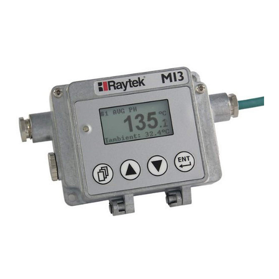
Operation 8 Operation Once you have the sensor positioned and connected properly, the system is ready for continuous operation. The control panel is accessible on the outside of the box. Push buttons provide positive tactile feedback to the user. User interface includes a backlit LCD, displaying sensor set up parameters and temperature outputs.
-
Page 49
Operation The head number is shown only if two or more sensing heads are connected to the communication box. Symbol/Message Meaning Remark Average Peak Hold Valley Hold HOLD Trigger set to HOLD function Advanced Peak Hold Software controlled APHA Advanced Peak Hold with Averaging Software controlled Advanced Valley Hold Software controlled… -
Page 50: Head> Page
Operation #1 (Head) #2 (Head) BOX SETUP BOX INFO Serial No. Tambient Relay Mode Rev. Tbox Emissivity OUT1 Mode* Transmiss. OUT1 Source* Laser* OUT1 Value* Average OUT1 low temp.* Peak Hold OUT1 high temp.* Val. Hold OUT2 Mode* Trigger OUT2 Source* Alarm Mode OUT2 Value* Set Point…
-
Page 51
Operation <Laser> handles the laser in the following modes: <off> switches the laser off <flash> forces the laser to blink at 8 Hz <on> switches the laser permanently on <external> switches the laser via external input FTC3 An activated laser will be switched off automatically after 10 minutes. The laser is available for 1M and 2M heads only. -
Page 52
Operation <OUT1 Mode> defines the mode for the analog output: <TCJ>, <TCK>, <TCR>, <TCS> <0-5V> <0-10V> <disable> output goes to high-resistance <OUT1 Source> assigns the selected head to the analog output: <#1>, <#2>, …, <Head > <OUT1 Value> defines the basis for the output value: <Tobject>: object temperature to be output <Tambient>: head ambient temperature to be output <OUT1 low temp.>… -
Page 53: Box Info> Page
Operation <Temperature Unit> the temperature unit can be set to °C or °F. Note that this setting influences the digital interfaces like RS485 for both object and head ambient temperature. <Key Enter Lock> the box has a user interface lockout feature that keeps the box from being accidentally changed from the control panel (locked by default under DataTemp Multidrop Software and Profinet communications).
-
Page 54: Peak Hold
Operation Attention: The disadvantage of averaging is the time delay of the output signal. If the temperature jumps at the input (hot object), the output signal reaches only 90% magnitude of the actual object temperature after the defined average time. 8.5.2 Peak Hold The output signal follows the object temperature until a maximum is reached.
-
Page 55: Advanced Peak Hold
Operation Temp output temperature object temperature hold time hold time Time Figure 37: Valley Hold A defined hold time of 999 s (symbol “∞” in the display) will put the device into continuous valley detection mode. A low level input (GND) at external input FTC3 will promptly interrupt the hold time and will start the minimum detection again.
-
Page 56: Advanced Valley Hold
Operation 8.5.5 Advanced Valley Hold This function works similar to the advanced peak hold function, except that it will search the signal for a local minimum. 8.5.6 Advanced Peak Hold with Averaging The output signal delivered by the advanced peak hold functions tends to jump up and down. This is due to the fact, that only maximum points of the otherwise homogenous trace will be shown.
-
Page 57: Options
Options 9 Options Options are items that are factory installed and must be specified at time of order. The following are available: Longer head cables in the lengths: 3 m / 9.8 ft. (…CB3) 8 m / 26 ft. (…CB8) 15 m / 49 ft.
-
Page 58: Avoidance Of Condensation
Options 9.1.1 Avoidance of Condensation If environmental conditions makes water cooling necessary, it is strictly recommended to check whether condensation will be a real problem or not. Water cooling also causes a cooling of the air in the inner part of the sensor, thereby decreasing the capability of the air to hold water. The relative humidity increases and can reach 100% very quickly.
-
Page 59: I Ntrinsic S Afety
9.2 Intrinsic Safety 9.2.1 Sensing Heads The sensing heads for the MI3, MI3xxLTH, and MI3100 series are available as intrinsic safety rated sensing heads (…IS) intended for use in explosive atmospheres. The sensing heads xxMI3xxxISx and xxxMI3100xxxISx follow the ATEX / IECEx certification in…
-
Page 60: Installation
IECEx Certificate of Conformity for Power Supply, page 142. 9.2.3 Installation The basic installation of sensing heads and the Ex Power Supply is shown in the following figure. MI3 Communication Box Ex Power Supply Explosion critical area 100 to 127 VAC 200 to 240 VAC Total sensing head cable length: max.
-
Page 61: Mains Supply
Options The standard data cable length to the communication box is 5 m (16 ft). In response to the interference in the environment the length of the cable may be up to 30 m (98 ft). Use only shielded cable with low capacitance about 100 pF/m (33pF/ft). The following illustration shows the external wiring of the Ex Power Supply with the sensing heads, the communication box and the mains supply.
-
Page 62
Options Before installation select the correct local mains voltage via the switch on the circuit board of the Ex Power Supply, see Figure 45. A ground wire must be connected to the (PE — protective earth) terminal on the circuit board of the Ex Power Supply. -
Page 63: Ex Power Supply 115Mi3Acis / 230Mi3Acis
Options 9.2.5 Ex Power Supply 115MI3ACIS / 230MI3ACIS The two variants of the Ex Power Supply without voltage selection switch are hard wired to the mains voltage. These devices are considered as nonsparking and may be installed in a non-hazardous area or in a hazardous area Zone 2 EPL Gc to supply power to intrinsically safe sensing heads.
-
Page 64: Accessories
Accessories 10 Accessories A full range of accessories for various applications and industrial environments are available. Accessories include items that may be ordered at any time and added on-site. 10.1 Accessories (all models) Multi-Channel Box (XXXMI3CONNBOX) USB/RS485 Adapter for boxes with RS485 interface (XXXUSB485) 10.1.1 Multi-Channel Box The Multi-Channel Box can be used for all communication boxes.
-
Page 65
Accessories Figure 48: Dimensions to Comm Box (MI3COMM or MI3MCOMM) Figure 49: Wiring Diagram for 8 Heads Rev. G Nov/2015… -
Page 66
Correct position of the shield before mounting Figure 50: Correct Mounting of the Cable Shield The total sensing head cable length for all networked sensing heads must not exceed 30 m/98 ft (for MI3) and 2×30 m/2×98 ft (for MI3M)! Rev. G Nov/2015… -
Page 67: Usb/Rs485 Adapter
Accessories 10.1.2 USB/RS485 Adapter The USB/RS485 adapter is self-powering via the USB connection. Figure 51: USB/RS485 Adapter (XXXUSB485) Termination Figure 52: Wiring the RS485 Interface of the Box (left) and USB/RS485 Adapter (right) Rev. G Nov/2015…
-
Page 68: A Ccessories (Lt, G5 H Eads )
Accessories 10.2 Accessories (LT, G5 Heads) Adjustable Mounting Bracket (XXXMIACAB) Fixed Mounting Bracket (XXXMIACFB) Sensing head mounting nut (XXXMIACMN) Air Purge Jacket (XXXMIACAJ) Air Cooling System with 0.8 m (2.6 ft.) air hose (XXXMIACCJ) or with 2.8 m (9.2 ft.) air hose (XXXMIACCJ1) …
-
Page 69: Adjustable Mounting Bracket
Accessories 10.2.1 Adjustable Mounting Bracket Figure 54: Adjustable Mounting Bracket (XXXMIACAB) Rev. G Nov/2015…
-
Page 70: Fixed Mounting Bracket
Accessories 10.2.2 Fixed Mounting Bracket Figure 55: Fixed Mounting Bracket (XXXMIACFB) 10.2.3 Air Purge Jacket For LTH sensing heads, the Air Purge Jacket is only available pre-mounted from the factory (XXXMIACAJI)! The air purge jacket is used to keep dust, moisture, airborne particles, and vapors away from the sensing head.
-
Page 71: Air Cooling System
Accessories Fitting to M5 inner thread Hose with inner diameter of 3 mm (0.12 in), outside 5 mm (0.2 in) Figure 56: Air Purge Jacket (XXXMIACAJ) Figure 57: Mounting the Air Purge Jacket Remove the sensor ① and cable from the communication box by disconnecting the wires from the terminal.
-
Page 72
Accessories max. ambient 200°C (392°F) max. ambient 50°C (122°F) Air Hose Sensing Head Cable Adapter Air cooling (max. 35°C / 95°F) Figure 58: Air Cooling System (XXXMIACCJ) T-Adapter Hose to sensing head Cable to box Fitting free for air connection Hose: inner Ø: 9 mm (0.35 in) outer Ø: 12 mm (0.47 in) -
Page 73
Accessories Air Flow: 60 l / min (2.1 cubic feet per minute) 50 l / min (1.8 cfm) 40 l / min (1.4 cfm) Hose Length Figure 60: Maximum Ambient Temperature is dependent on Air Flow and Hose Length Note: “Hose Length“ is the length of the hose exposed to high ambient temperature (not the overall length of the hose). -
Page 74
Accessories Figure 61: Air Cooling System: Purging Jacket and T-Adapter The Air Cooling System consists of: ① sensing head ② inner plastic fitting (air purge jacket) ③ front part of the air-purging jacket ④ back part of the air-purging jacket ⑤… -
Page 75: Right Angle Mirror
Accessories Hose: inner Ø: 9 mm (0.35 in) outer Ø: 12 mm (0.47 in) Figure 62: Dimensions of Air Cooling System 10.2.5 Right Angle Mirror The right angle mirror comes in two different versions: XXXMIACRAJ right angle mirror as accessory for air purge jacket or air cooling system XXXMIACRAJ1 right angle mirror with integrated air purge (not available for LTH sensing heads) Figure 63: Right Angle Mirror XXXMIACRAJ (left),…
-
Page 76: Protective Windows
Accessories The IR beam length within the right angle mirror is 18 mm (0.7 in.) which needs to be considered for spot size calculations. 10.2.6 Protective Windows Protective windows can be used to protect the sensing head from dust and other contamination. The protective window can be directly screwed onto the sensing head.
-
Page 77
Accessories For correct temperature readings, the transmission of the close focus lens must be set via the control panel in the communication box. See section 8.2 <Head> Page, page 50! Make sure the measuring head and the close focus lens are at the same temperature! Figure 66: Sensing Head with Close Focus Lens (XXXMI3ACCFL) Figure 67: Spot Size Charts for Close Focus Lens Rev. -
Page 78: A Ccessories (1M, 2M H Eads )
Accessories 10.3 Accessories (1M, 2M Heads) Fixed Mounting Bracket (XXXMI3100FB) Adjustable Mounting Bracket (XXXMI3100ADJB) Isolation Kit (MI3100ISOKIT) Air Purge Collar (XXXMI3100AP) Right Angle Mirror (XXXMI3100RAM) Protective Window (XXXMI3100PW) Air Purge Collar Sensing Head Mounting Nut Fixed Mounting Bracket Protective Window…
-
Page 79: Fixed Mounting Bracket
Accessories 10.3.1 Fixed Mounting Bracket Figure 69: Dimensions of Fixed Mounting Bracket (XXXMI3100FB) Rev. G Nov/2015…
-
Page 80: Adjustable Mounting Bracket
Accessories 10.3.2 Adjustable Mounting Bracket Figure 70: Dimensions of Adjustable Mounting Bracket (XXXMI3100ADJB) Rev. G Nov/2015…
-
Page 81: Isolation Kit
Accessories 10.3.3 Isolation Kit The isolation kit (MI3100ISOKIT) can be used likewise for the fixed mounting bracket (XXXMI3100FB) and the adjustable mounting bracket (XXXMI3100ADJB). Two non-conductive rings insulate the sensing head (1M, 2M) electrically from the mounting bracket. The isolation kit is used to implement installations with one earth grounded point only, see section 4.5 Electrical Interference, page 24.
-
Page 82: Right Angle Mirror
Accessories 10.3.5 Right Angle Mirror The Right Angle Mirror is used to turn the field of view by 90° against the sensor axis. It is recommended when space limitations or excessive radiation do not allow for direct alignment of the sensor to the target.
-
Page 83: Protective Window
Accessories 10.3.6 Protective Window Protective windows can be used to protect the sensing head from dust and other contamination. The protective window can be directly screwed onto the sensing head. The following table provides an overview of the available windows. Order number Material Transmission…
-
Page 84: Maintenance
Maintenance 11 Maintenance Our sales representatives are always at your disposal for questions regarding application assistance, calibration, repair, and solutions to specific problems. Please contact your local sales representative, if you need assistance. In many cases, problems can be solved over the telephone. If you need to return equipment for servicing, calibration, or repair, please call our Service Department for authorization prior to return.
-
Page 85: Cleaning The Lens
Maintenance Symptom Temperature over range > 1200°C > 1372°C > 1768°C > 1768°C (2192°F) (2502°F) (3214°F) (3214°F) Temperature under range -210°C -210°C -50°C -50°C (-346°F) (-346°F) (-58°F) (-58°F) Head ambient temperature out of range > 1200°C > 1372°C > 1768°C >…
-
Page 86: S Ensing H Ead E Xchange
Maintenance Do not use any ammonia or any cleaners containing ammonia to clean the lens. This may result in permanent damage to the lens’ surface! 11.4 Sensing Head Exchange To exchange a sensing head, the following procedure is required: Disconnect power to the box. Disconnect all head wires from the box terminal.
-
Page 87: Software Features
DataTemp Multidrop Software 12 DataTemp Multidrop Software 12.1 Software Features DataTemp Multidrop DTMD provides sensor setup, remote monitoring, and simple data logging for analysis or to meet quality record-keeping requirements. Additional features configurable with DTMD Software: Eight-position “recipe” table that can be easily interfaced to an external control system …
-
Page 88: Rs485
RS485 13 RS485 The RS485 serial interface is used for long distances up to 1200 m (4000 ft) or for networked communication boxes. To connect the RS485 interface to a standard computer you should use a dedicated adapter, see section 10.1.2 USB/RS485 Adapter, page 67.
-
Page 89: Profibus
Profibus 14 Profibus Profibus DP-V0 defines a cyclical data exchange between a master (e.g. a PLC) and a slave (MI3 sensor). At start-up first an array of parameters (Profibus specific data) is sent from the master to the slave, followed by an array with the configuration (sensor specific presetting’s taken from the GSD file) also sent from the master to the slave.
-
Page 90
Profibus A Sub-D female connector or a M12 female connector can be ordered separately for Profibus. The M12 connector is B-coded. Please note the Sub-D connector is not IP rated! Figure 77: Sub-D Connector (…P2) and M12 Connector (…P1) Profibus Sub-D Pin M12 Pin (cable color) -
Page 91: Comm Box (Din)
Profibus 14.1.2 Comm Box (DIN) Termination Indicator Profibus n.a. Shield (negative signal) (not supported while termination “on”) (positive signal) (not supported while termination “on”) (negative signal) (positive signal) Shield n.a. , yellow ON: data-exchange Figure 80: Terminal for Comm Box (DIN 6TE) Rev.
-
Page 92: P Rogramming
Profibus 14.2 Programming 14.2.1 Parameter Data Byte Address Description Format Range without offset 0 to 6 DP-V1 Status1 DP-V1 Status2 DP-V1 Status3 Temp. unit 67=°C, 70=°F 67 or 70 Reserved 12, 13 Bottom temp. of output 1 in 0.1°C /°F 14, 15 Top temp.
-
Page 93: Input Data
Profibus Byte Address Description Format Range without offset Laser Head_1 0 = off, 1 = on, 0 or 1 2 = flashing 60…63 reserved, for future consideration 64 … Head_2 84 … Head_3 104 … Head_4 124 … Head_5 144 … Head_6 164 ……
-
Page 94: Output Data
Profibus 14.2.3 Output Data The device does not have output data in the original meaning. But the output data may be used to change the initialization of the device (which was set once at start-up) when the bus is in data exchange mode.
-
Page 95
up to which index the user data is valid 11 (0x0B) box error code 12 … 22 (0x0C …16) last MI3-command which created an error as answer; ASCII code 23 (0x17) head_1 error code 24 (0x18) -
Page 96
Profibus Highest Last bad head Head 1 Head 8 error bits error bits Figure 82: Diagnose Data with Error “Cable Break at Head 1” Rev. G Nov/2015… -
Page 97: Modbus
Modbus 15 Modbus The Modbus protocol follows the master/slave model. One master controls one or more slaves. Typically, the master sends a request to a slave, which in turn sends a response. The request/response mechanism is called a transaction. Requests and responses are also referred to as messages. Specification: Version: Modbus serial line (RS485)
-
Page 98: Comm Box (Din)
Modbus 15.1.2 Comm Box (DIN) Termination Indicators Modbus (output) Shield D0_2 (negative signal) (not supported while termination “on”) D1_2 (positive signal) (not supported while termination “on”) D0_1 (negative signal) D1_1 (positive signal) Shield (output) n.a. , yellow Communication , red Error Figure 84: Terminal for Comm Box (DIN 6TE) Rev.
-
Page 99: P Rogramming
Comm Box. Items (registers, discretes or coils) are addressed starting at zero. Therefore items numbered 1-10000 are addressed as 0-9999. Start Size Modbus Access Data Content Values MI3[M] address [bits] Type command input register short error code for last…
-
Page 100
Modbus Start Size Modbus Access Data Content Values MI3[M] address [bits] Type command discretes input bit field Get connected heads bit 0: head 1 .. bit 7: head 8 bit high: head connected bit low: head disconnected discretes input bit field Get registered heads bit 0: head 1 .. -
Page 101: Head Parameter
Modbus 15.2.2.2 Head Parameter <n> … head number, depending on the registered heads Starting Size Modbus Data Content Values MI3[M] address [bits] Access Type command <n>005 discretes bit field Head Status bit0: Temperature Unit input (0: deg. C, 1: deg. F)
-
Page 102
Modbus Starting Size Modbus Data Content Values MI3[M] address [bits] Access Type command <n>220 holding char Emissivity Source I: internal command register E: ext. input (0V .. 5V) D: digital selected FTC1-3 <n>230 holding float Presel. Emissivity 0.1 .. 1.1 register <n>240… -
Page 103: Ethernet
(port 80) capability supporting up to 8 sensing heads Connection: M12 or RJ45 electrically isolated An opened Ethernet port will be closed automatically by the MI3 communication box if there is no data traffic within the time given by the <TTI> command! 16.1 Wiring 16.1.1 Comm Box (metal) The connector on the box side is an M12 plug-in connector, 4 pin D-coded, suited for industrial Ethernet with IP67 protection rate with a screw retention feature.
-
Page 104: A Ddressing
The factory default IP address for the linescanner is 192.168.42.130. The IP address for the MI3 is not free of choice: It has to be unique in the network meaning that no other device in the network including the PC network adapter may run at the same IP address. The IP address for the MI3 can be set directly via the control panel.
-
Page 105: Pc Network Adapter
103. The MI3 subnet address must be 193.221.142 as well. The host address of the MI3 must be in the range from 1 to 254 with the exception of 103 which is already used for the PC.
-
Page 106: Ascii P Rogramming
4. Activate the radio button <Use the following IP address> and make the following settings: IP address: 192.168.42.x where x is an address between 0 and 255 except 130 which is already used by the MI3 by factory default Subnet mask: 255.255.255.0 Default gateway: {empty} 5.
-
Page 107: Http S Erver
Ethernet 16.4 http Server The MI3 Comm Box with Ethernet provides a built-in http server for one or more client computers based on the http protocol within an Intranet. For getting/setting the network address through the control panel of the Comm Box, see section 8.3 <Box Setup>…
-
Page 108
1 The data logging function is password protectable to ensure data consistency while having multiple clients connected to the MI3 http server. A valid password accepts digits only! The factory presetting is 1234. -
Page 109: Profinet
Profinet 17 Profinet The Profinet fieldbus MI3 communication box (called fieldbus communicator) maps the object and internal temperature of all pyrometer modules on Profinet IO. In the initialization phase, the fieldbus communicator determines the physical structure of the node and creates a local process image with all pyrometers.
-
Page 110: P Rogramming
Pyrometer modules is based on the device’s GSD file. 17.2.1.1 GSD File Under Profinet IO, the features of the devices are described by the manufacturer in form of a GSD file and made available to the user. The GSD file for the MI3 IO device: GSDML-V2.25-Raytek-MI3-xxxxxxxx 17.2.1.2 Configuration The I/O device is configured in accordance with the physical arrangement of the node (slot oriented).
-
Page 111: Parameters Of The Fieldbus Communicator
Profinet 17.2.2.1 Parameters of the Fieldbus Communicator The parameters of the fieldbus communicator are used to set the overall settings of the Profinet IO node. Some of the setting are used in the modules as default settings and can be optionally overwritten within the module configuration.
-
Page 112
Profinet Figure 90: Parameters of the Fieldbus Communicator (exemplary for a STEP7 environment) Rev. G Nov/2015… -
Page 113: Parameters Of The Pyrometer Module
Profinet 17.2.2.2 Parameters of the Pyrometer Module Certain characteristics of same pyrometer modules can be parameterized during the configuration. Parameter Description Setting Pyrometer number Set the number of pyrometer 1..8 Emissivity * 1000 (0.9 900) 100 … 1100 Transmissivity * 1000 (1.0 …
-
Page 114: Input Data Structure
Profinet 17.2.3 Input Data Structure 17.2.3.1 Input Data of Fieldbus Communicator The input data length is 5 Byte. Address without offset Length Format Value 1 Byte Bit0 Trigger state ( 0 – inactive, 1 – active) 4 Byte Real (Big Endian, Motorola) Internal temperature of the station 17.2.3.2 Input Data of Pyrometer Module The input data length of pyrometer module is 8 Byte.
-
Page 115
Profinet indicator in APDU-Status is set by the communicator and a diagnostic alarm is additionally transmitted. As part of the diagnosis of the fieldbus communicator, bit 2 indicates a communication error to the pyrometer module. In this case, a diagnostic interrupt is triggered for the I/O controller. As part of the diagnosis of the pyrometer module, bit 6 indicates a communication error to the registered pyrometer module. -
Page 116: Ascii Programming
ASCII Programming 18 ASCII Programming This section explains the system’s ASCII communication protocols. A protocol is the set of commands that defines all possible communications with the sensor. The commands are described along with their associated ASCII command characters and related message format information. Use them when writing custom programs for your applications or when communicating with your sensor using a terminal program.
-
Page 117: A Ddressing
ASCII Programming Setting a parameter (Poll Mode) The parameter will be stored into the device EEPROM. E=0.975<CR> “E“ is the parameter to be set “=“ is the command for “set a parameter“ “0.975“ is the value for the parameter <CR> (carriage return, 0Dh) is closing the request Remark: It is possible to close with <CR>…
-
Page 118: D Evice I Nformation
ASCII Programming Examples requests the emissivity for sensing head at address 2 on the single box 2E=0.975 sets the emissivity to 0.975 for sensing head at address 2 on the single box !2E0.975 sensing head at address 2 confirms the emissivity setting on the single box 017E=0.5 Sets emissivity on head #1 on box 017 0171E=0.5…
-
Page 119: Emissivity Setting And Alarm Set Points
ASCII Programming 18.5.3 Emissivity Setting and Alarm Set points The device allows three choices for the emissivity setting and two for the alarm output setting. Selection of the emissivity setting ES=I Emissivity set by a constant number according to the „E“ command ES=E Emissivity set by a voltage on FTC1 (analog input) ES=D…
-
Page 120: Device Control
ASCII Programming Advanced Peak/Valley Hold with Averaging: C=250.0 threshold: 250°C AA=15.0 averaging time (90%): 15 s 18.6 Dynamic Data All temperature related information is calculated multiple times per second. To request the dynamic data, the following commands are available: target temperature internal temperature of the sensing head internal temperature of the electronics housing energy value of the infrared temperature…
-
Page 121: Command Set
ASCII Programming KB=1 relay contacts permanently closed KB=2 relay contacts normally open KB=3 relay contacts normally closed XS=125.3 threshold setting to 125.3°C (if U=C is set) 18.7.4 Factory default values It is possible to reset the unit to the default values. factory default values will be set 18.7.5 Lock Mode The access to the unit is possible via serial interface (software) and via the direct user input (mode…
-
Page 122
ASCII Programming Description Char Format P B S N Legal Values Factory default Head / Ambient background °C/°F 23°C temp. compensation float Advanced hold with 0 – 999.0 s 000.0s average float Control ambient 0 –… -
Page 123
ASCII Programming Description Char Format P B S N Legal Values Factory default Head / External module 0 – no module 2 – 2 channels 4 – 4 channels (analog outputs) Presel. Emissivity 0 — 7 Pointer integer Emissivity Source … -
Page 124
control integer 1 = on 2 = Target norm. open depreciated for MI3 (use 3 = Target norm. closed the commands KB and 4 = Intern norm. open KH instead of) 5 = Intern norm. closed Relay alarm output … -
Page 125
ASCII Programming Description Char Format P B S N Legal Values Factory default Head / Output 1 source O1O=v, v – float value O1O=1I or nT, n – head number or nI if v = 60 – controlled by head 1(O1O=1T) Output 2 source O2O=v,… -
Page 126
ASCII Programming Description Char Format P B S N Legal Values Factory default Head / Sensor initialization 1 after reset 0 if XI=0 Box Temperature float (C/F) FTC3 trigger/hold T = trigger, H = hold analog Output 1 mode XO1O XO1O=v 0 –… -
Page 127
ASCII Programming 18.8.1 ASCII Commands for Ethernet and Profinet Description Char Format P B S N Legal Values Factory default Head / IP address 192.xxx.xxx.xxx 192.168.42.130 2.19 (Ethernet) 0.0.0.0 (Profinet) Net Mask 255.255.255.0 255.255.255.0 2.19 (Ethernet) 0.0.0.0 (Profinet) Gateway… -
Page 128: Appendix
Appendix 19 Appendix 19.1 Determination of Emissivity Emissivity is a measure of an object’s ability to absorb and emit infrared energy. It can have a value between 0 and 1.0. For example a mirror has an emissivity of < 0.1, while the so-called “Blackbody“ reaches an emissivity value of 1.0.
-
Page 129
Appendix ETALS Material Emissivity 3.9 µm 5 µm 8 – 14 µm Aluminum Unoxidized 0.02-0.2 0.02-0.2 0.02-0.1 Oxidized 0.2-0.4 0.2-0.4 0.2-0.4 Alloy A3003, Oxidized Roughened 0.1-0.4 0.1-0.4 0.1-0.3 Polished 0.02-0.1 0.02-0.1 0.02-0.1 Brass Polished 0.01-0.05 0.01-0.05 0.01-0.05 Burnished Oxidized Chromium 0.03-0.3 0.03-0.3 0.02-0.2… -
Page 130
Appendix Polished Sheet Molten 0.1-0.2 0.1-0.2 — Oxidized 0.7-0.9 0.7-0.9 0.7-0.9 Stainless 0.15-0.8 0.15-0.8 0.1-0.8 Tin (Unoxidized) 0.05 0.05 0.05 Titanium Polished 0.1-0.3 0.1-0.3 0.05-0.2 Oxidized 0.5-0.7 0.5-0.7 0.5-0.6 Tungsten 0.05-0.5 0.05-0.5 0.03 Polished 0.05-0.25 0.05-0.25 0.03-0.1 Zinc Oxidized Polished 0.03 0.03 0.02… -
Page 131
Appendix ETALS Material Emissivity 3.9 µm 5 µm 8 – 14 µm Asbestos 0.95 Asphalt 0.95 0.95 Basalt Carbon Unoxidized 0.8-0.9 0.8-0.9 Graphite 0.7-0.9 0.7-0.8 Carborundum Ceramic 0.8-0.95 0.95 Clay 0.85-0.95 0.95 Concrete 0.95 Cloth 0.95 0.95 Glass Plate 0.98 0.85 “Gob”… -
Page 132: C Onformity For S Ensing H Eads
Appendix 19.3 ATEX Certificate of Conformity for Sensing Heads Rev. G Nov/2015…
-
Page 133
Appendix Rev. G Nov/2015… -
Page 134
Appendix Rev. G Nov/2015… -
Page 135
Appendix 19.4 ATEX Certificate of Conformity for Ex Power Supply Rev. G Nov/2015… -
Page 136
Appendix Rev. G Nov/2015… -
Page 137
Appendix Rev. G Nov/2015… -
Page 138: C Onformity For S Ensing H Eads
Appendix 19.5 IECEx Certificate of Conformity for Sensing Heads Rev. G Nov/2015…
-
Page 139
Appendix Rev. G Nov/2015… -
Page 140
Appendix Rev. G Nov/2015… -
Page 141
Appendix Rev. G Nov/2015… -
Page 142: C Onformity For P Ower S Upply
Appendix 19.6 IECEx Certificate of Conformity for Power Supply Rev. G Nov/2015…
-
Page 143
Appendix Rev. G Nov/2015… -
Page 144
Appendix Rev. G Nov/2015… -
Page 145
Appendix Rev. G Nov/2015… -
Page 146
Notes 20 Notes Rev. G Nov/2015…
RAYMI31001MSF3 – датчик пирометра
Назначение серии пирометров Raytek MI3
Серия компактных термометров Raytek MI3
На смену серии ИК стационарных термометров Thermalert MID, Raytek выпустил серию компактных термометров MI3, с расширенными возможностями и улучшенными техническими характеристиками. Преемственность старых моделей MID и новых MI3 сохранена.
Наличие USB интерфейса в стандартном комплекте поставки, расширенный диапазон температуры и дополнительные функции обработки сигнала, позволяют встраивать датчики MI3 в системы автоматизации производственных процессов, использовать их в комплексном оборудовании.
Система MI3 состоит из датчика MI3 и блока электроники (защита IP65). Датчик и блок заказываются отдельно!
Особенности серии пирометров Raytek MI3
- Подключение до 8 датчиков к одному блоку электроники
- Концепция быстрого подключения Plug & Play
- Работа до 120 °C /180 °C без охлаждения
- Различные спектральные диапазоны
- Расширенный температурный диапазон (для LT до 1000 °C)
- Новая модель G5 до 1650 °C (5 мкм) для стекла
- Пятно измерения от 0,5 мм (“ Close Focus“)
- Модели “Fast» с временем отклика 10 мс
- Промышленный кабель (полиуретан): устойчив к маслам, кислотам и щелочам
- Лазерный прицел для 1M/2M
Технические характеристики датчика RAY MI3 100 1M SF3
|
Общие данные |
|
|
Диапазон измерения |
500… 1800°C |
|
Спектральный диапазон |
1 μm |
|
Оптическое разрешение1 |
100:1, фокус 2 мм@2200 мм |
|
Точность2 |
±(0,5% измер±2°C) 4 |
|
Воспроизводимость |
±(0,25% измер. ±1°C) |
|
Температурный коэффициент |
±0,05% /K от измер. |
|
Время отклика6 |
130 мс |
|
Коэффициент излучения |
0,100 … 1,100 |
|
Коэффициент пропускания |
0,100 … 1,100 |
|
Обработка сигнала |
Расчет и фиксация макс., мин. и средних значений, настройка по времени до 998 с |
|
Температура работы |
0 … 120°C, laser — автоматическое выключение при 65°C |
|
Температура хранения |
-20 … 120° |
|
Стандарт защиты |
IP65 |
|
Защита от электромагнитных полей |
EN 61326-1:2006 |
|
1 90% энергии 2 при окружающей температуре 23°C ± 5°C, ε = 1.0 3 что больше 4 ± 2°C при температуре < 20°C 5 для масштабируемого интервала < 500°C 6 90% |
Комплектация датчика Raytek MI3
- Датчик пирометра;
- Руководство по эксплуатации.
Дополнительная комплектация датчика Raytek MI3
- Длина кабеля: 3 м, 8 м, 15 м, 30 м
- Датчик для OEM систем, не требующий блока электроники
- Регулируемый монтажный кронштейн
XXXMIACAB для LT, G5 / XXXMI3100ADJB 1M, 2M - Корпус воздушного охлаждения (XXXMIACCJ: 0,8 м, XXXMIACCJ1: 2,8
Технические параметры (спецификация) и комплект поставки товара могут быть изменены производителем без предварительного уведомления.
Информация носит справочный характер и не является публичной офертой, определяемой положениями Статьи 437 Гражданского кодекса Российской Федерации.
Документы, файлы, паспорт, инструкция Raytek MI3 100 1M SF3
Наличие уточняйте у менеджера
![]()
Уточнить наличие
Нашли дешевле? Снизим цену!


Самовывоз
ул. Подольских Курсантов, 17, к.2

Время доставки
от 2-х дней при наличии на складе

Гарантия:
24 месяца

Госреестр:
Товар внесен в Госреестр СИ (ГРСИ)
Наши преимущества

Бесплатная доставка
по всей территории России

Гарантия низкой цены
на все оборудование

Гарантия производителя
от 1 года до 5 лет

Официальный дилер
в наличии все сертификаты
Описание стационарного инфракрасного пирометра RAYTEK серии MI3
Тип оборудования: Стационарный пирометр, инфракрасный термометр, бесконтактный пирометр
Производитель: RAYTEK (Райтек), Германия
Серия: MI3
Модель: MI3
Гарантия: 2 года
Госреестр средств измерений РФ: Внесен
Поверка: Включена в стоимость
Серия компактных термометров Raytek MI3
На смену серии ИК стационарных термометров Thermalert MID, Raytek выпустил серию компактных термометров MI3, с расширенными возможностями и улучшенными техническими характеристиками. Преемственность старых моделей MID и новых MI3 сохранена.
Наличие USB интерфейса в стандартном комплекте поставки, расширенный диапазон температуры и дополнительные функции обработки сигнала, позволяют встраивать датчики MI3 в системы автоматизации производственных процессов, использовать их в комплексном оборудовании.
Особенности
• Подключение до 8 датчиков к одному блоку электроники
• Концепция быстрого подключения Plug & Play
• Работа до 120 °C /180 °C без охлаждения
• Различные спектральные диапазоны
• Расширенный температурный диапазон (для LT до 1000 °C)
• Новая модель G5 до 1650 °C (5 мкм) для стекла
• Пятно измерения от 0,5 мм (“ Close Focus“)
• Модели “Fast» с временем отклика 10 мс
• Промышленный кабель (полиуретан): устойчив к маслам, кислотам и щелочам
• Лазерный прицел для 1M/2M
Диапазон измерений
| LTS02, LTS10,LTH10 | -40 … 600 °C |
| LTS20, LTF,LTH20 | 0 … 1000 °C |
| G5 | 250 … 1650 °C |
| 2M | 250…1400 °C |
| 1M | 500…1800 °C |
Дополнительные материалы
Загруженных файлов нет
Как купить?
Сделать заказ через интернет-магазин в нашем каталоге продукции
В течение рабочего дня Вам будет выставлен счет на оплату, в котором будет указано наименование
товара, цена, количество и срок отгрузки в Ваш адрес.
Направить нам заявку по электронной почте, указанной на странице
выбранного Вами товара.
В заявке необходимо указать наименование и количество нужного Вам товара, а также реквизиты
организации плательщика.
Посетить наш офис, сделать заявку и получить счет на оплату в отделе
продаж
В выставочном зале Вы можете ознакомиться с предлагаемыми нами оборудованием, а технические
специалисты помогут Вам выбрать нужную продукцию.
Доставка
Мы имеем возможность доставки товара в любую точку России, интересующей транспортной компанией или
курьерской службой:
Товар можно доставить как до терминала транспортной компании, так и, непосредственно, до двери.
Стоимость доставки рассчитывается специалистами логистической службы нашей компании в кратчайшие
сроки
в необходимое место по желанию заказчика.
Уточнить условия и стоимость доставки Вы можете, связавшись со специалистами нашей компании.
Оплата
Юридическим лицам
С юридическими лицами отношения регламентируются договором, счетом на оплату, товарной накладной,
счет-фактурой (УПД) и безналичным переводом денежных средств из банка Покупателя на расчетный счет
Продавца.
Физическим лицам
Физическое лицо также может произвести оплату на наш расчетный счет банковским переводом или
наличными средствами. При получении товара передается пакет документов: оригинал счета на оплату
продукции, товарная накладная и счет-фактура (УПД).
Похожие товары
Наши услуги
Узнайте цену
Для получения цены заполните форму, наши менеджеры обязательно с Вами свяжутся
Уточнить наличие
Для уточнения наличия заполните форму, наши менеджеры обязательно с Вами свяжутся
Получить скидку в компании «АНК»
Для получения скидки заполните форму, наши менеджеры обязательно с Вами свяжутся
Задать вопрос специалистам компании «АНК»
Задайте вопрос по интересующему Вас оборудованию и в ближайшее время наши специалисты с Вами свяжутся.
Остались вопросы?
Получите бесплатную консультацию у наших менеджеров!

-
Page 1: Operating Instructions
Miniature Infrared Sensor Operating Instructions Rev. G Nov/2015 55201…
-
Page 3
Thank you for purchasing this Raytek product. Register today at www.raytek.com/register to receive the latest updates, enhancements and software upgrades! © Raytek Corporation. Raytek and the Raytek Logo are registered trademarks of Raytek Corporation. All rights reserved. Specifications subject to change without notice. -
Page 4
ARRANTY The manufacturer warrants this product to be free from defects in material and workmanship under normal use and service for the period of two years from date of purchase, except as hereinafter provided. This warranty extends only to the original purchaser (a purchase from the manufacturer or a licensed distributor of the manufacturer is an original purchase). -
Page 5: Table Of Contents
Content CONTENT …………………………..5 1 SAFETY INSTRUCTIONS ……………………..10 2 DESCRIPTION …………………………13 2.1 O ··························································································································· 14 VERVIEW OXES 3 TECHNICAL DATA ……………………….15 3.1 M ················································································································· 15 EASUREMENT PECIFICATION 3.1.1 Sensing Heads ……………………….. 15 3.1.2 Comm Box ……………………….16 3.1.2.1 Comm Box (metal) ………………………..
-
Page 6
5.4 W ··································································································································· 29 IRING ERMINAL 5.4.1 Comm Box (metal) ……………………..29 5.4.2 Comm Box (DIN 3TE) ……………………30 5.4.3 Comm Box (DIN 4 TE) ……………………31 5.4.4 Comm Box (DIN 6 TE) ……………………32 5.4.5 EMI Resistance for Comm Box (DIN) ………………..35 5.5 P ····························································································································… -
Page 7
9.2.4 Mains Supply ……………………….61 9.2.5 Ex Power Supply 115MI3ACIS / 230MI3ACIS …………….63 10 ACCESSORIES ………………………… 64 10.1 A ) ···················································································································· 64 CCESSORIES ALL MODELS 10.1.1 Multi-Channel Box ……………………… 64 10.1.2 USB/RS485 Adapter ……………………. 67 10.2 A (LT, G5 H ) ·················································································································… -
Page 8: Data Logging
··················································································································································· 103 IRING 16.1.1 Comm Box (metal) …………………….. 103 16.1.2 Comm Box (DIN) ……………………… 103 16.2 A ··········································································································································· 104 DDRESSING 16.2.1 MI3 …………………………104 16.2.2 PC Network Adapter ……………………105 16.3 ASCII P ··························································································································· 106 ROGRAMMING 16.4 ·········································································································································· 107 HTTP ERVER 16.4.1 Data Logging ……………………..
-
Page 9: Lock Mode
18.7.4 Factory default values ……………………121 18.7.5 Lock Mode ……………………….121 18.7.6 Mode Setting for the Digital Input FTC3 ………………121 18.7.7 Ambient Background Temperature Compensation …………….. 121 18.8 C ······································································································································· 121 OMMAND 18.8.1 ASCII Commands for Ethernet and Profinet ……………… 127 19 APPENDIX …………………………
-
Page 10: Safety Instructions
Safety Instructions 1 Safety Instructions This document contains important information, which should be kept at all times with the instrument during its operational life. Other users of this instrument should be given these instructions with the instrument. Eventual updates to this information must be added to the original document. The instrument should only be operated by trained personnel in accordance with these instructions and local safety regulations.
-
Page 11
Safety Instructions Safety Symbols AC (Alternating Current) DC (Direct Current) Risk of danger. Important information. See manual. Hazardous voltage. Risk of electrical shock. Helpful information regarding the optimal use of the instrument. Earth ground Protective ground Fuse Normally-open (NO) relay Normally-closed (NC) relay Switch or relay contact DC power supply… -
Page 12
Safety Instructions The instrument can be equipped with a Class 2 laser. Class 2 lasers shine only within the visible spectrum at an intensity of 1 mW. Looking directly into the laser beam can produce a slight, temporary blinding effect, but does not result in physical injury or damage to the eyes, even when the beam is magnified by optical aids. -
Page 13: Description
Description 2 Description The MI3 sensor series is the next generation of the well-established “MI class” sensor platform. It will be capable of covering a broad range of applications. The MI3 sensor series introduces various network communications, an externally accessible user interface, improved temperature measurement specifications and capabilities at an economic price.
-
Page 14: Overview Comm Boxe
Description 2.1 Overview Comm Boxes MI3COMM MI3MCOMMN MI3MCOMM MI3MCOMM… metal box DIN 3TE DIN 4TE DIN 6TE Part number MI3COMM… MI3MCOMMN MI3MCOMM MI3MCOMM… Spectral Heads LT, G5, 1M, 2M LT, G5, 1M, 2M LT, G5, 1M, 2M LT, G5, 1M, 2M Head Support by firmware 8 heads…
-
Page 15: Technical Data
Technical Data 3 Technical Data 3.1 Measurement Specification 3.1.1 Sensing Heads Temperature Range LTS02, LTS10, LTH10 -40 to 600°C (-40 to 1112°F) LTS20, LTF, LTH20 0 to 1000°C (32 to 1832°F) 250 to 1650°C (482 to 3002°F) 250 to 1400°C (482 to 2552°F) 500 to 1800°C (932 to 3272°F) Spectral Response 8 to 14 µm…
-
Page 16: Comm Box
Technical Data 3.1.2 Comm Box Accuracy mA/V output ± 1°C (corresponds to ± 0.015 mA for the current output at 0-20 mA or ± 0.015 mA for the current output at 4-20 mA or 4 mV for the voltage output at 0-5 V or 8 mV for the voltage output at 0-10 V) TC output ±…
-
Page 17: O Ptical C Harts
Technical Data 3.2 Optical Charts Figure 1: Spot Size Charts Rev. G Nov/2015…
-
Page 18: E Lectrical S Pecification
Technical Data 3.3 Electrical Specification For an overview to the capabilities of the communication boxes, see section 2.1 Overview Comm Boxes, page 14. 3.3.1 Comm Box, all models Voltage Supply 8 to 32 VDC Power Consumption max. 6 W Alarm Output 1 potential-free relay output, 48 V / 300 mA Relay with wear-free contacts (solid state relay) for target temperature or head ambient temperature, electrically isolated from power supply…
-
Page 19: E Nvironmental S Pecification
Technical Data 3.4 Environmental Specification 3.4.1 Sensing Head Ambient Temperature LT, G5 -10 to 120°C (14 to 248°F) -10 to 180°C (14 to 356°F) 1M, 2M 0 to 120°C (32 to 248°F) Laser (1M, 2M) automatic switch off at 65°C (149°F) Storage Temperature -20 to 180°C (-4 to 356°F) all other models…
-
Page 20: Comm Box (Din)
Technical Data Electromagnetic Compatibility Applies to use in Korea only. Class A Equipment (Industrial Broadcasting & Communication Equipment) This product meets requirements for industrial (Class A) electromagnetic wave equipment and the seller or user should take notice of it. This equipment is intended for use in business environments and is not to be used in homes.
-
Page 21: D Imensions
Technical Data 3.5 Dimensions 3.5.1 Sensing Head LT, G5 Standard cable length 1 m (3 ft.) Ø 5 mm (0.2 in) Figure 2: Dimensions of LT, G5 Sensing Heads 3.5.2 Sensing Head LTH Figure 3: Dimensions of LTH Sensing Head with separated Electronics 3.5.3 Sensing Head 1M, 2M Standard cable length 1 m (3 ft)
-
Page 22: Scope Of Delivery
Technical Data Figure 5: Dimensions of Communication Box 3.5.5 Comm Box (DIN) The boxes come in a standard DIN rail size in accordance to EN 50022-35×7.5 (DIN 43880). Width MI3MCOMMN MI3MCOMM MI3MCOMM… DIN 3TE: DIN 4TE: DIN 6TE: 53.6 mm (2.1 in) 71.6 mm (2.8 in) 107.6 mm (4.2 in) Figure 6: Dimensions for Comm Boxes (DIN)
-
Page 23: Comm Box
Technical Data 3.6.2 Comm Box Communication box for Comm Box (DIN) only — XXXMI3MCOMMSET: ferrite cores (4 pcs), shield tapes (4 pcs) Software DVD Quickstart guide Rev. G Nov/2015…
-
Page 24: Basics
Basics 4 Basics 4.1 Measurement of Infrared Temperature All surfaces emit infrared radiation. The intensity of this infrared radiation changes according to the temperature of the object. Depending on the material and surface properties, the emitted radiation lies in a wavelength spectrum of approximately 1 to 20 µm. The intensity of the infrared radiation (heat radiation) is dependent on the material.
-
Page 25
Comm Box, or power. Please note that: The metal housings of the sensing head and the MI3 communication box are electrically connected to the shield of the head cable. All inputs and outputs (except the alarm output and the outputs of the Comm Box (DIN 6TE, analog)) use the same ground and are electrically connected to the power supply. -
Page 26: Installation
Installation 5 Installation 5.1 Positioning Sensor location depends on the application. Before deciding on a location, you need to be aware of the ambient temperature of the location, the atmospheric quality of the location, and the possible electromagnetic interference in that location. If you plan to use air purging, you need to have an air connection available.
-
Page 27: Comm Box (Din)
Installation Comm Box Power supply, (RAYMI3COMM) 2 analog Head 1 outputs, (RAYMI3…) 3 inputs Fieldbus Figure 11: Single Head Configuration with Comm Box To increase the number of supported sensing heads, you can use a dedicated accessory, see section 10.1.1 Multi-Channel Box, page 64.
-
Page 28: Comm Box (Metal)
The total sensing head cable length for all networked sensing heads must not exceed 30 m (98 ft) for MI3 and 2×30 m (2×98 ft) for MI3M! Do not add a third party cable to extend the length of the sensing head cable! 5.3.1 Comm Box (metal)
-
Page 29: Comm Box (Din)
Installation 5.3.2 Comm Box (DIN) The wiring of the sensing head cable is color coded, see section 5.4.3 Comm Box (DIN 4 TE), page 31. 5.4 Wiring, Terminal You need to connect the power supply and possibly the signal input/output wires. Use only cable with outside diameter from 4 to 6 mm (0.16 to 0.24 in), wire size: 0.14 to 0.75 mm²…
-
Page 30: Comm Box (Din 3Te)
Installation 5.4.2 Comm Box (DIN 3TE) Sensing Heads USB Connector, Mini-B Figure 15: Terminal Wiring for the Comm Box DIN 3TE Rev. G Nov/2015…
-
Page 31: Comm Box (Din 4 Te)
Installation 5.4.3 Comm Box (DIN 4 TE) Sensing Heads Termination USB Connector, Mini-B Figure 16: Terminal Wiring for the Comm Box DIN 4 TE Rev. G Nov/2015…
-
Page 32: Comm Box (Din 6 Te)
Installation 5.4.4 Comm Box (DIN 6 TE) Sensing Heads Wiring Profibus or Modbus USB Connector, Mini-B Figure 17: Terminal Wiring for the Comm Box DIN 6 TE for Profibus and Modbus Rev. G Nov/2015…
-
Page 33
Installation Sensing Heads USB Connector, Mini-B RJ45 connector Profinet or Ethernet Figure 18: Terminal Wiring for the Comm Box DIN 6 TE for Profinet and Modbus Rev. G Nov/2015… -
Page 34
Installation Sensing Heads see section Analog Outputs OUT1 — OUT4, page 41. Analog Outputs USB Connector, Mini-B Figure 19: Terminal Wiring for the Comm Box DIN 6 TE, analog Rev. G Nov/2015… -
Page 35: Emi Resistance For Comm Box (Din)
Installation 5.4.5 EMI Resistance for Comm Box (DIN) To maintain EMI compliance to CE standards the attached Ferrite cores need to be placed on all wires! Make sure that the cable shields will be connected to the terminal pin <Shield>! self-adhesive shield tape to wrap round the cable Shield wire connected to…
-
Page 36: Power On Procedure
Installation 5.5 Power On Procedure To power the system, the following procedures are required. 5.5.1 One Head System Disconnect power to the box. Connect the wires for the head to the box terminal. Power the box. The box now assigns address 1 to the head. 5.5.2 Multiple Heads –…
-
Page 37
Installation 5.6 USB The USB interface comes with each box (USB connector, Mini-B). Connect a single unit to a USB computer port by using an appropriate USB cable. USB connector, type Mini-B The computer’s USB port Figure 21: USB Connection via the Comm Box (metal) The computer’s USB port Figure 22: USB Connection via the Comm Box (DIN Rail) Rev. -
Page 38
Installation Consider the following sequence for the installation: Disconnect/reconnect the USB interface cable to the computer! Ignore the Windows Wizard <Found New Hardware>! Navigate manually to the dedicated USB driver <RaytekMIcomport.inf> on the support media and execute it. It is strongly recommended to check the correct driver installation under the Windows Operating System <Start>… -
Page 39: F Ieldbus
Installation 5.7 Fieldbus A simultaneous communication via USB and fieldbus is not allowed! 5.7.1 Addressing Each slave in the network must have a unique address and must run at the same baud rate! For setting the fieldbus configurations through the control panel, see section 8.3 <Box Setup>…
-
Page 40: Outputs
Outputs 6 Outputs For the outputs the following groupings (setups) are possible: Output Setup 1 Setup 2 Setup 3 Setup 4 Setup 5 OUT1 head temperature head temperature object temperature object temperature OUT2 object temperature object temperature object temperature object temperature head temperature object temperature…
-
Page 41: A Nalog O Utputs Out1 — Out4
Outputs 6.3 Analog Outputs OUT1 — OUT4 Comm Box: DIN 6TE, analog (4 channels) Source: object temperature / head ambient temperature Signal: 0/4 to 20 mA or 0 to 5/10 V Terminal: , GND Each signal output can be configured as either current or voltage output, whereby each sensing head can be assigned to each output.
-
Page 42: T Hermocouple O Utput Tc
Outputs 6.5 Thermocouple Output TC Comm Box: metal Source: object temperature Signal: TCJ, TCK, TCR, or TCS Terminal: TC, GND This output can be configured as thermocouple output type J, K, R, or S. For that output, you must install a dedicated compensation cable. The output impedance is 20 Ω. The output is short circuit resistant.
-
Page 43: Inputs
Inputs 7 Inputs Three external inputs FTC1, FTC2, and FTC3 are used for the external control of the unit. You cannot enable the input functions through the control panel! FTC1 FTC2 FTC3 Emissivity (analog control) Emissivity (digital control) Ambient Background Temperature Compensation Trigger/Hold Function Laser Switching Table 2: Overview for FTC Inputs…
-
Page 44: E Missivity ( Digital )
Inputs + 5 VDC “product 1” R1 = 200 Ω 4.0 V (ε=0.9) To the FTC input R2 = 500 Ω of the box 1.5 V (ε=0.4) “product 2” R3 = 300 Ω Figure 25: Adjustment of Emissivity at FTC Input (Example) 7.2 Emissivity (digital) Function: emissivity (digital control)
-
Page 45
Inputs The sensor is capable of improving the accuracy of target temperature measurements by taking into account the ambient or background temperature. This feature is useful when the target emissivity is below 1.0 and the background temperature is significantly hotter than the target temperature. For instance, the higher temperature of a furnace wall could lead to hotter temperatures being measured especially for low emissivity targets. -
Page 46: Trigger/Hold
Inputs 7.4 Trigger/Hold Function: Trigger/Hold Signal: digital low/high Terminal: FTC3, GND The FTC3 input can be used as an external trigger functioning as “Trigger” or “Hold”. All sensing heads are effected by the FTC3 input at the same time. Figure 28: Wiring of FTC3 as Trigger/Hold Trigger: A logical low signal at the input FTC3 will reset the peak or valley hold function.
-
Page 47: L Aser S Witching
Inputs object temperature Temp output temperature Trigger Time Figure 30: FTC3 for Holding the Output Temperature 7.5 Laser Switching Function: Laser switching on/off Signal: digital low/high Terminal: FTC3, GND The FTC3 input can also be used as an external trigger to switch the laser (only available for selected sensing head models).
-
Page 48: Control Panel
Operation 8 Operation Once you have the sensor positioned and connected properly, the system is ready for continuous operation. The control panel is accessible on the outside of the box. Push buttons provide positive tactile feedback to the user. User interface includes a backlit LCD, displaying sensor set up parameters and temperature outputs.
-
Page 49
Operation The head number is shown only if two or more sensing heads are connected to the communication box. Symbol/Message Meaning Remark Average Peak Hold Valley Hold HOLD Trigger set to HOLD function Advanced Peak Hold Software controlled APHA Advanced Peak Hold with Averaging Software controlled Advanced Valley Hold Software controlled… -
Page 50: Head> Page
Operation #1 (Head) #2 (Head) BOX SETUP BOX INFO Serial No. Tambient Relay Mode Rev. Tbox Emissivity OUT1 Mode* Transmiss. OUT1 Source* Laser* OUT1 Value* Average OUT1 low temp.* Peak Hold OUT1 high temp.* Val. Hold OUT2 Mode* Trigger OUT2 Source* Alarm Mode OUT2 Value* Set Point…
-
Page 51
Operation <Laser> handles the laser in the following modes: <off> switches the laser off <flash> forces the laser to blink at 8 Hz <on> switches the laser permanently on <external> switches the laser via external input FTC3 An activated laser will be switched off automatically after 10 minutes. The laser is available for 1M and 2M heads only. -
Page 52
Operation <OUT1 Mode> defines the mode for the analog output: <TCJ>, <TCK>, <TCR>, <TCS> <0-5V> <0-10V> <disable> output goes to high-resistance <OUT1 Source> assigns the selected head to the analog output: <#1>, <#2>, …, <Head > <OUT1 Value> defines the basis for the output value: <Tobject>: object temperature to be output <Tambient>: head ambient temperature to be output <OUT1 low temp.>… -
Page 53: Box Info> Page
Operation <Temperature Unit> the temperature unit can be set to °C or °F. Note that this setting influences the digital interfaces like RS485 for both object and head ambient temperature. <Key Enter Lock> the box has a user interface lockout feature that keeps the box from being accidentally changed from the control panel (locked by default under DataTemp Multidrop Software and Profinet communications).
-
Page 54: Peak Hold
Operation Attention: The disadvantage of averaging is the time delay of the output signal. If the temperature jumps at the input (hot object), the output signal reaches only 90% magnitude of the actual object temperature after the defined average time. 8.5.2 Peak Hold The output signal follows the object temperature until a maximum is reached.
-
Page 55: Advanced Peak Hold
Operation Temp output temperature object temperature hold time hold time Time Figure 37: Valley Hold A defined hold time of 999 s (symbol “∞” in the display) will put the device into continuous valley detection mode. A low level input (GND) at external input FTC3 will promptly interrupt the hold time and will start the minimum detection again.
-
Page 56: Advanced Valley Hold
Operation 8.5.5 Advanced Valley Hold This function works similar to the advanced peak hold function, except that it will search the signal for a local minimum. 8.5.6 Advanced Peak Hold with Averaging The output signal delivered by the advanced peak hold functions tends to jump up and down. This is due to the fact, that only maximum points of the otherwise homogenous trace will be shown.
-
Page 57: Options
Options 9 Options Options are items that are factory installed and must be specified at time of order. The following are available: Longer head cables in the lengths: 3 m / 9.8 ft. (…CB3) 8 m / 26 ft. (…CB8) 15 m / 49 ft.
-
Page 58: Avoidance Of Condensation
Options 9.1.1 Avoidance of Condensation If environmental conditions makes water cooling necessary, it is strictly recommended to check whether condensation will be a real problem or not. Water cooling also causes a cooling of the air in the inner part of the sensor, thereby decreasing the capability of the air to hold water. The relative humidity increases and can reach 100% very quickly.
-
Page 59: I Ntrinsic S Afety
9.2 Intrinsic Safety 9.2.1 Sensing Heads The sensing heads for the MI3, MI3xxLTH, and MI3100 series are available as intrinsic safety rated sensing heads (…IS) intended for use in explosive atmospheres. The sensing heads xxMI3xxxISx and xxxMI3100xxxISx follow the ATEX / IECEx certification in…
-
Page 60: Installation
IECEx Certificate of Conformity for Power Supply, page 142. 9.2.3 Installation The basic installation of sensing heads and the Ex Power Supply is shown in the following figure. MI3 Communication Box Ex Power Supply Explosion critical area 100 to 127 VAC 200 to 240 VAC Total sensing head cable length: max.
-
Page 61: Mains Supply
Options The standard data cable length to the communication box is 5 m (16 ft). In response to the interference in the environment the length of the cable may be up to 30 m (98 ft). Use only shielded cable with low capacitance about 100 pF/m (33pF/ft). The following illustration shows the external wiring of the Ex Power Supply with the sensing heads, the communication box and the mains supply.
-
Page 62
Options Before installation select the correct local mains voltage via the switch on the circuit board of the Ex Power Supply, see Figure 45. A ground wire must be connected to the (PE — protective earth) terminal on the circuit board of the Ex Power Supply. -
Page 63: Ex Power Supply 115Mi3Acis / 230Mi3Acis
Options 9.2.5 Ex Power Supply 115MI3ACIS / 230MI3ACIS The two variants of the Ex Power Supply without voltage selection switch are hard wired to the mains voltage. These devices are considered as nonsparking and may be installed in a non-hazardous area or in a hazardous area Zone 2 EPL Gc to supply power to intrinsically safe sensing heads.
-
Page 64: Accessories
Accessories 10 Accessories A full range of accessories for various applications and industrial environments are available. Accessories include items that may be ordered at any time and added on-site. 10.1 Accessories (all models) Multi-Channel Box (XXXMI3CONNBOX) USB/RS485 Adapter for boxes with RS485 interface (XXXUSB485) 10.1.1 Multi-Channel Box The Multi-Channel Box can be used for all communication boxes.
-
Page 65
Accessories Figure 48: Dimensions to Comm Box (MI3COMM or MI3MCOMM) Figure 49: Wiring Diagram for 8 Heads Rev. G Nov/2015… -
Page 66
Correct position of the shield before mounting Figure 50: Correct Mounting of the Cable Shield The total sensing head cable length for all networked sensing heads must not exceed 30 m/98 ft (for MI3) and 2×30 m/2×98 ft (for MI3M)! Rev. G Nov/2015… -
Page 67: Usb/Rs485 Adapter
Accessories 10.1.2 USB/RS485 Adapter The USB/RS485 adapter is self-powering via the USB connection. Figure 51: USB/RS485 Adapter (XXXUSB485) Termination Figure 52: Wiring the RS485 Interface of the Box (left) and USB/RS485 Adapter (right) Rev. G Nov/2015…
-
Page 68: A Ccessories (Lt, G5 H Eads )
Accessories 10.2 Accessories (LT, G5 Heads) Adjustable Mounting Bracket (XXXMIACAB) Fixed Mounting Bracket (XXXMIACFB) Sensing head mounting nut (XXXMIACMN) Air Purge Jacket (XXXMIACAJ) Air Cooling System with 0.8 m (2.6 ft.) air hose (XXXMIACCJ) or with 2.8 m (9.2 ft.) air hose (XXXMIACCJ1) …
-
Page 69: Adjustable Mounting Bracket
Accessories 10.2.1 Adjustable Mounting Bracket Figure 54: Adjustable Mounting Bracket (XXXMIACAB) Rev. G Nov/2015…
-
Page 70: Fixed Mounting Bracket
Accessories 10.2.2 Fixed Mounting Bracket Figure 55: Fixed Mounting Bracket (XXXMIACFB) 10.2.3 Air Purge Jacket For LTH sensing heads, the Air Purge Jacket is only available pre-mounted from the factory (XXXMIACAJI)! The air purge jacket is used to keep dust, moisture, airborne particles, and vapors away from the sensing head.
-
Page 71: Air Cooling System
Accessories Fitting to M5 inner thread Hose with inner diameter of 3 mm (0.12 in), outside 5 mm (0.2 in) Figure 56: Air Purge Jacket (XXXMIACAJ) Figure 57: Mounting the Air Purge Jacket Remove the sensor ① and cable from the communication box by disconnecting the wires from the terminal.
-
Page 72
Accessories max. ambient 200°C (392°F) max. ambient 50°C (122°F) Air Hose Sensing Head Cable Adapter Air cooling (max. 35°C / 95°F) Figure 58: Air Cooling System (XXXMIACCJ) T-Adapter Hose to sensing head Cable to box Fitting free for air connection Hose: inner Ø: 9 mm (0.35 in) outer Ø: 12 mm (0.47 in) -
Page 73
Accessories Air Flow: 60 l / min (2.1 cubic feet per minute) 50 l / min (1.8 cfm) 40 l / min (1.4 cfm) Hose Length Figure 60: Maximum Ambient Temperature is dependent on Air Flow and Hose Length Note: “Hose Length“ is the length of the hose exposed to high ambient temperature (not the overall length of the hose). -
Page 74
Accessories Figure 61: Air Cooling System: Purging Jacket and T-Adapter The Air Cooling System consists of: ① sensing head ② inner plastic fitting (air purge jacket) ③ front part of the air-purging jacket ④ back part of the air-purging jacket ⑤… -
Page 75: Right Angle Mirror
Accessories Hose: inner Ø: 9 mm (0.35 in) outer Ø: 12 mm (0.47 in) Figure 62: Dimensions of Air Cooling System 10.2.5 Right Angle Mirror The right angle mirror comes in two different versions: XXXMIACRAJ right angle mirror as accessory for air purge jacket or air cooling system XXXMIACRAJ1 right angle mirror with integrated air purge (not available for LTH sensing heads) Figure 63: Right Angle Mirror XXXMIACRAJ (left),…
-
Page 76: Protective Windows
Accessories The IR beam length within the right angle mirror is 18 mm (0.7 in.) which needs to be considered for spot size calculations. 10.2.6 Protective Windows Protective windows can be used to protect the sensing head from dust and other contamination. The protective window can be directly screwed onto the sensing head.
-
Page 77
Accessories For correct temperature readings, the transmission of the close focus lens must be set via the control panel in the communication box. See section 8.2 <Head> Page, page 50! Make sure the measuring head and the close focus lens are at the same temperature! Figure 66: Sensing Head with Close Focus Lens (XXXMI3ACCFL) Figure 67: Spot Size Charts for Close Focus Lens Rev. -
Page 78: A Ccessories (1M, 2M H Eads )
Accessories 10.3 Accessories (1M, 2M Heads) Fixed Mounting Bracket (XXXMI3100FB) Adjustable Mounting Bracket (XXXMI3100ADJB) Isolation Kit (MI3100ISOKIT) Air Purge Collar (XXXMI3100AP) Right Angle Mirror (XXXMI3100RAM) Protective Window (XXXMI3100PW) Air Purge Collar Sensing Head Mounting Nut Fixed Mounting Bracket Protective Window…
-
Page 79: Fixed Mounting Bracket
Accessories 10.3.1 Fixed Mounting Bracket Figure 69: Dimensions of Fixed Mounting Bracket (XXXMI3100FB) Rev. G Nov/2015…
-
Page 80: Adjustable Mounting Bracket
Accessories 10.3.2 Adjustable Mounting Bracket Figure 70: Dimensions of Adjustable Mounting Bracket (XXXMI3100ADJB) Rev. G Nov/2015…
-
Page 81: Isolation Kit
Accessories 10.3.3 Isolation Kit The isolation kit (MI3100ISOKIT) can be used likewise for the fixed mounting bracket (XXXMI3100FB) and the adjustable mounting bracket (XXXMI3100ADJB). Two non-conductive rings insulate the sensing head (1M, 2M) electrically from the mounting bracket. The isolation kit is used to implement installations with one earth grounded point only, see section 4.5 Electrical Interference, page 24.
-
Page 82: Right Angle Mirror
Accessories 10.3.5 Right Angle Mirror The Right Angle Mirror is used to turn the field of view by 90° against the sensor axis. It is recommended when space limitations or excessive radiation do not allow for direct alignment of the sensor to the target.
-
Page 83: Protective Window
Accessories 10.3.6 Protective Window Protective windows can be used to protect the sensing head from dust and other contamination. The protective window can be directly screwed onto the sensing head. The following table provides an overview of the available windows. Order number Material Transmission…
-
Page 84: Maintenance
Maintenance 11 Maintenance Our sales representatives are always at your disposal for questions regarding application assistance, calibration, repair, and solutions to specific problems. Please contact your local sales representative, if you need assistance. In many cases, problems can be solved over the telephone. If you need to return equipment for servicing, calibration, or repair, please call our Service Department for authorization prior to return.
-
Page 85: Cleaning The Lens
Maintenance Symptom Temperature over range > 1200°C > 1372°C > 1768°C > 1768°C (2192°F) (2502°F) (3214°F) (3214°F) Temperature under range -210°C -210°C -50°C -50°C (-346°F) (-346°F) (-58°F) (-58°F) Head ambient temperature out of range > 1200°C > 1372°C > 1768°C >…
-
Page 86: S Ensing H Ead E Xchange
Maintenance Do not use any ammonia or any cleaners containing ammonia to clean the lens. This may result in permanent damage to the lens’ surface! 11.4 Sensing Head Exchange To exchange a sensing head, the following procedure is required: Disconnect power to the box. Disconnect all head wires from the box terminal.
-
Page 87: Software Features
DataTemp Multidrop Software 12 DataTemp Multidrop Software 12.1 Software Features DataTemp Multidrop DTMD provides sensor setup, remote monitoring, and simple data logging for analysis or to meet quality record-keeping requirements. Additional features configurable with DTMD Software: Eight-position “recipe” table that can be easily interfaced to an external control system …
-
Page 88: Rs485
RS485 13 RS485 The RS485 serial interface is used for long distances up to 1200 m (4000 ft) or for networked communication boxes. To connect the RS485 interface to a standard computer you should use a dedicated adapter, see section 10.1.2 USB/RS485 Adapter, page 67.
-
Page 89: Profibus
Profibus 14 Profibus Profibus DP-V0 defines a cyclical data exchange between a master (e.g. a PLC) and a slave (MI3 sensor). At start-up first an array of parameters (Profibus specific data) is sent from the master to the slave, followed by an array with the configuration (sensor specific presetting’s taken from the GSD file) also sent from the master to the slave.
-
Page 90
Profibus A Sub-D female connector or a M12 female connector can be ordered separately for Profibus. The M12 connector is B-coded. Please note the Sub-D connector is not IP rated! Figure 77: Sub-D Connector (…P2) and M12 Connector (…P1) Profibus Sub-D Pin M12 Pin (cable color) -
Page 91: Comm Box (Din)
Profibus 14.1.2 Comm Box (DIN) Termination Indicator Profibus n.a. Shield (negative signal) (not supported while termination “on”) (positive signal) (not supported while termination “on”) (negative signal) (positive signal) Shield n.a. , yellow ON: data-exchange Figure 80: Terminal for Comm Box (DIN 6TE) Rev.
-
Page 92: P Rogramming
Profibus 14.2 Programming 14.2.1 Parameter Data Byte Address Description Format Range without offset 0 to 6 DP-V1 Status1 DP-V1 Status2 DP-V1 Status3 Temp. unit 67=°C, 70=°F 67 or 70 Reserved 12, 13 Bottom temp. of output 1 in 0.1°C /°F 14, 15 Top temp.
-
Page 93: Input Data
Profibus Byte Address Description Format Range without offset Laser Head_1 0 = off, 1 = on, 0 or 1 2 = flashing 60…63 reserved, for future consideration 64 … Head_2 84 … Head_3 104 … Head_4 124 … Head_5 144 … Head_6 164 ……
-
Page 94: Output Data
Profibus 14.2.3 Output Data The device does not have output data in the original meaning. But the output data may be used to change the initialization of the device (which was set once at start-up) when the bus is in data exchange mode.
-
Page 95
up to which index the user data is valid 11 (0x0B) box error code 12 … 22 (0x0C …16) last MI3-command which created an error as answer; ASCII code 23 (0x17) head_1 error code 24 (0x18) -
Page 96
Profibus Highest Last bad head Head 1 Head 8 error bits error bits Figure 82: Diagnose Data with Error “Cable Break at Head 1” Rev. G Nov/2015… -
Page 97: Modbus
Modbus 15 Modbus The Modbus protocol follows the master/slave model. One master controls one or more slaves. Typically, the master sends a request to a slave, which in turn sends a response. The request/response mechanism is called a transaction. Requests and responses are also referred to as messages. Specification: Version: Modbus serial line (RS485)
-
Page 98: Comm Box (Din)
Modbus 15.1.2 Comm Box (DIN) Termination Indicators Modbus (output) Shield D0_2 (negative signal) (not supported while termination “on”) D1_2 (positive signal) (not supported while termination “on”) D0_1 (negative signal) D1_1 (positive signal) Shield (output) n.a. , yellow Communication , red Error Figure 84: Terminal for Comm Box (DIN 6TE) Rev.
-
Page 99: P Rogramming
Comm Box. Items (registers, discretes or coils) are addressed starting at zero. Therefore items numbered 1-10000 are addressed as 0-9999. Start Size Modbus Access Data Content Values MI3[M] address [bits] Type command input register short error code for last…
-
Page 100
Modbus Start Size Modbus Access Data Content Values MI3[M] address [bits] Type command discretes input bit field Get connected heads bit 0: head 1 .. bit 7: head 8 bit high: head connected bit low: head disconnected discretes input bit field Get registered heads bit 0: head 1 .. -
Page 101: Head Parameter
Modbus 15.2.2.2 Head Parameter <n> … head number, depending on the registered heads Starting Size Modbus Data Content Values MI3[M] address [bits] Access Type command <n>005 discretes bit field Head Status bit0: Temperature Unit input (0: deg. C, 1: deg. F)
-
Page 102
Modbus Starting Size Modbus Data Content Values MI3[M] address [bits] Access Type command <n>220 holding char Emissivity Source I: internal command register E: ext. input (0V .. 5V) D: digital selected FTC1-3 <n>230 holding float Presel. Emissivity 0.1 .. 1.1 register <n>240… -
Page 103: Ethernet
(port 80) capability supporting up to 8 sensing heads Connection: M12 or RJ45 electrically isolated An opened Ethernet port will be closed automatically by the MI3 communication box if there is no data traffic within the time given by the <TTI> command! 16.1 Wiring 16.1.1 Comm Box (metal) The connector on the box side is an M12 plug-in connector, 4 pin D-coded, suited for industrial Ethernet with IP67 protection rate with a screw retention feature.
-
Page 104: A Ddressing
The factory default IP address for the linescanner is 192.168.42.130. The IP address for the MI3 is not free of choice: It has to be unique in the network meaning that no other device in the network including the PC network adapter may run at the same IP address. The IP address for the MI3 can be set directly via the control panel.
-
Page 105: Pc Network Adapter
103. The MI3 subnet address must be 193.221.142 as well. The host address of the MI3 must be in the range from 1 to 254 with the exception of 103 which is already used for the PC.
-
Page 106: Ascii P Rogramming
4. Activate the radio button <Use the following IP address> and make the following settings: IP address: 192.168.42.x where x is an address between 0 and 255 except 130 which is already used by the MI3 by factory default Subnet mask: 255.255.255.0 Default gateway: {empty} 5.
-
Page 107: Http S Erver
Ethernet 16.4 http Server The MI3 Comm Box with Ethernet provides a built-in http server for one or more client computers based on the http protocol within an Intranet. For getting/setting the network address through the control panel of the Comm Box, see section 8.3 <Box Setup>…
-
Page 108
1 The data logging function is password protectable to ensure data consistency while having multiple clients connected to the MI3 http server. A valid password accepts digits only! The factory presetting is 1234. -
Page 109: Profinet
Profinet 17 Profinet The Profinet fieldbus MI3 communication box (called fieldbus communicator) maps the object and internal temperature of all pyrometer modules on Profinet IO. In the initialization phase, the fieldbus communicator determines the physical structure of the node and creates a local process image with all pyrometers.
-
Page 110: P Rogramming
Pyrometer modules is based on the device’s GSD file. 17.2.1.1 GSD File Under Profinet IO, the features of the devices are described by the manufacturer in form of a GSD file and made available to the user. The GSD file for the MI3 IO device: GSDML-V2.25-Raytek-MI3-xxxxxxxx 17.2.1.2 Configuration The I/O device is configured in accordance with the physical arrangement of the node (slot oriented).
-
Page 111: Parameters Of The Fieldbus Communicator
Profinet 17.2.2.1 Parameters of the Fieldbus Communicator The parameters of the fieldbus communicator are used to set the overall settings of the Profinet IO node. Some of the setting are used in the modules as default settings and can be optionally overwritten within the module configuration.
-
Page 112
Profinet Figure 90: Parameters of the Fieldbus Communicator (exemplary for a STEP7 environment) Rev. G Nov/2015… -
Page 113: Parameters Of The Pyrometer Module
Profinet 17.2.2.2 Parameters of the Pyrometer Module Certain characteristics of same pyrometer modules can be parameterized during the configuration. Parameter Description Setting Pyrometer number Set the number of pyrometer 1..8 Emissivity * 1000 (0.9 900) 100 … 1100 Transmissivity * 1000 (1.0 …
-
Page 114: Input Data Structure
Profinet 17.2.3 Input Data Structure 17.2.3.1 Input Data of Fieldbus Communicator The input data length is 5 Byte. Address without offset Length Format Value 1 Byte Bit0 Trigger state ( 0 – inactive, 1 – active) 4 Byte Real (Big Endian, Motorola) Internal temperature of the station 17.2.3.2 Input Data of Pyrometer Module The input data length of pyrometer module is 8 Byte.
-
Page 115
Profinet indicator in APDU-Status is set by the communicator and a diagnostic alarm is additionally transmitted. As part of the diagnosis of the fieldbus communicator, bit 2 indicates a communication error to the pyrometer module. In this case, a diagnostic interrupt is triggered for the I/O controller. As part of the diagnosis of the pyrometer module, bit 6 indicates a communication error to the registered pyrometer module. -
Page 116: Ascii Programming
ASCII Programming 18 ASCII Programming This section explains the system’s ASCII communication protocols. A protocol is the set of commands that defines all possible communications with the sensor. The commands are described along with their associated ASCII command characters and related message format information. Use them when writing custom programs for your applications or when communicating with your sensor using a terminal program.
-
Page 117: A Ddressing
ASCII Programming Setting a parameter (Poll Mode) The parameter will be stored into the device EEPROM. E=0.975<CR> “E“ is the parameter to be set “=“ is the command for “set a parameter“ “0.975“ is the value for the parameter <CR> (carriage return, 0Dh) is closing the request Remark: It is possible to close with <CR>…
-
Page 118: D Evice I Nformation
ASCII Programming Examples requests the emissivity for sensing head at address 2 on the single box 2E=0.975 sets the emissivity to 0.975 for sensing head at address 2 on the single box !2E0.975 sensing head at address 2 confirms the emissivity setting on the single box 017E=0.5 Sets emissivity on head #1 on box 017 0171E=0.5…
-
Page 119: Emissivity Setting And Alarm Set Points
ASCII Programming 18.5.3 Emissivity Setting and Alarm Set points The device allows three choices for the emissivity setting and two for the alarm output setting. Selection of the emissivity setting ES=I Emissivity set by a constant number according to the „E“ command ES=E Emissivity set by a voltage on FTC1 (analog input) ES=D…
-
Page 120: Device Control
ASCII Programming Advanced Peak/Valley Hold with Averaging: C=250.0 threshold: 250°C AA=15.0 averaging time (90%): 15 s 18.6 Dynamic Data All temperature related information is calculated multiple times per second. To request the dynamic data, the following commands are available: target temperature internal temperature of the sensing head internal temperature of the electronics housing energy value of the infrared temperature…
-
Page 121: Command Set
ASCII Programming KB=1 relay contacts permanently closed KB=2 relay contacts normally open KB=3 relay contacts normally closed XS=125.3 threshold setting to 125.3°C (if U=C is set) 18.7.4 Factory default values It is possible to reset the unit to the default values. factory default values will be set 18.7.5 Lock Mode The access to the unit is possible via serial interface (software) and via the direct user input (mode…
-
Page 122
ASCII Programming Description Char Format P B S N Legal Values Factory default Head / Ambient background °C/°F 23°C temp. compensation float Advanced hold with 0 – 999.0 s 000.0s average float Control ambient 0 –… -
Page 123
ASCII Programming Description Char Format P B S N Legal Values Factory default Head / External module 0 – no module 2 – 2 channels 4 – 4 channels (analog outputs) Presel. Emissivity 0 — 7 Pointer integer Emissivity Source … -
Page 124
control integer 1 = on 2 = Target norm. open depreciated for MI3 (use 3 = Target norm. closed the commands KB and 4 = Intern norm. open KH instead of) 5 = Intern norm. closed Relay alarm output … -
Page 125
ASCII Programming Description Char Format P B S N Legal Values Factory default Head / Output 1 source O1O=v, v – float value O1O=1I or nT, n – head number or nI if v = 60 – controlled by head 1(O1O=1T) Output 2 source O2O=v,… -
Page 126
ASCII Programming Description Char Format P B S N Legal Values Factory default Head / Sensor initialization 1 after reset 0 if XI=0 Box Temperature float (C/F) FTC3 trigger/hold T = trigger, H = hold analog Output 1 mode XO1O XO1O=v 0 –… -
Page 127
ASCII Programming 18.8.1 ASCII Commands for Ethernet and Profinet Description Char Format P B S N Legal Values Factory default Head / IP address 192.xxx.xxx.xxx 192.168.42.130 2.19 (Ethernet) 0.0.0.0 (Profinet) Net Mask 255.255.255.0 255.255.255.0 2.19 (Ethernet) 0.0.0.0 (Profinet) Gateway… -
Page 128: Appendix
Appendix 19 Appendix 19.1 Determination of Emissivity Emissivity is a measure of an object’s ability to absorb and emit infrared energy. It can have a value between 0 and 1.0. For example a mirror has an emissivity of < 0.1, while the so-called “Blackbody“ reaches an emissivity value of 1.0.
-
Page 129
Appendix ETALS Material Emissivity 3.9 µm 5 µm 8 – 14 µm Aluminum Unoxidized 0.02-0.2 0.02-0.2 0.02-0.1 Oxidized 0.2-0.4 0.2-0.4 0.2-0.4 Alloy A3003, Oxidized Roughened 0.1-0.4 0.1-0.4 0.1-0.3 Polished 0.02-0.1 0.02-0.1 0.02-0.1 Brass Polished 0.01-0.05 0.01-0.05 0.01-0.05 Burnished Oxidized Chromium 0.03-0.3 0.03-0.3 0.02-0.2… -
Page 130
Appendix Polished Sheet Molten 0.1-0.2 0.1-0.2 — Oxidized 0.7-0.9 0.7-0.9 0.7-0.9 Stainless 0.15-0.8 0.15-0.8 0.1-0.8 Tin (Unoxidized) 0.05 0.05 0.05 Titanium Polished 0.1-0.3 0.1-0.3 0.05-0.2 Oxidized 0.5-0.7 0.5-0.7 0.5-0.6 Tungsten 0.05-0.5 0.05-0.5 0.03 Polished 0.05-0.25 0.05-0.25 0.03-0.1 Zinc Oxidized Polished 0.03 0.03 0.02… -
Page 131
Appendix ETALS Material Emissivity 3.9 µm 5 µm 8 – 14 µm Asbestos 0.95 Asphalt 0.95 0.95 Basalt Carbon Unoxidized 0.8-0.9 0.8-0.9 Graphite 0.7-0.9 0.7-0.8 Carborundum Ceramic 0.8-0.95 0.95 Clay 0.85-0.95 0.95 Concrete 0.95 Cloth 0.95 0.95 Glass Plate 0.98 0.85 “Gob”… -
Page 132: C Onformity For S Ensing H Eads
Appendix 19.3 ATEX Certificate of Conformity for Sensing Heads Rev. G Nov/2015…
-
Page 133
Appendix Rev. G Nov/2015… -
Page 134
Appendix Rev. G Nov/2015… -
Page 135
Appendix 19.4 ATEX Certificate of Conformity for Ex Power Supply Rev. G Nov/2015… -
Page 136
Appendix Rev. G Nov/2015… -
Page 137
Appendix Rev. G Nov/2015… -
Page 138: C Onformity For S Ensing H Eads
Appendix 19.5 IECEx Certificate of Conformity for Sensing Heads Rev. G Nov/2015…
-
Page 139
Appendix Rev. G Nov/2015… -
Page 140
Appendix Rev. G Nov/2015… -
Page 141
Appendix Rev. G Nov/2015… -
Page 142: C Onformity For P Ower S Upply
Appendix 19.6 IECEx Certificate of Conformity for Power Supply Rev. G Nov/2015…
-
Page 143
Appendix Rev. G Nov/2015… -
Page 144
Appendix Rev. G Nov/2015… -
Page 145
Appendix Rev. G Nov/2015… -
Page 146
Notes 20 Notes Rev. G Nov/2015…
-
RayTek MI Miniature Infrared Sensor — page 1
MI Miniature Infrared Sensor Operating Instructions Rev. F 04/2006 54301 …
-
RayTek MI Miniature Infrared Sensor — page 2
Declaratio n of Conformity for the European Communit y This instrument conforms to: EMC: IEC/EN 61326 ‐ 1 Safety: EN 61010 ‐ 1:1993 / A2:1995 …
-
RayTek MI Miniature Infrared Sensor — page 3
Contacts Europe Raytek GmbH 13127 Berlin, German y Blankenburger Str. 135 Tel: +49 30 478008 – 0 +49 30 478008 – 400 Fax: +49 30 4710251 raytek@raytek.de USA Raytek Corporation CA 95061 – 1820, Santa …
-
RayTek MI Miniature Infrared Sensor — page 4
W ARRANTY The manufacturer warrants this ins trument to be free from defects in material and workmans hip under normal use and service for the period of two years fr om date of purchase. This warranty extends o …
-
RayTek MI Miniature Infrared Sensor — page 5
T ABLE OF C ONTENTS 1 SAFETY INSTRUCTIONS…………………………………….. 1 2 DESCRIPTION ……………………………………………………… 3 3 TECHNICAL DATA ……………………………………………… 4 3.1 M EASUREMENT S PECIFICATIONS ……………………… …
-
RayTek MI Miniature Infrared Sensor — page 6
5.3.1 Signal Output …………………………………………… 19 5.3.2 Head Ambient Temp. / Alarm Out p ut …………. 20 5.3.3 Thermo couple Output ………………………………… 22 5.4 I NPUTS FTC…………………………………………………….. 23 5.4.1 …
-
RayTek MI Miniature Infrared Sensor — page 7
8 ACCESSORIES ……………………………………………………. 46 8.1 O VERVIEW ………………………………………………………. 46 8.2 A DJUSTABLE M OUNTING B RACKET ……………………. 48 8.3 F IXED M OUNTING B RACKET ……………………………… 49 8.4 A IR ? …
-
RayTek MI Miniature Infrared Sensor — page 8
11.6.2 Analog Output, Scaling …………………………… 73 11.6.3 Alarm Output…………………………………………. 73 11.6.4 Factory defaul t values ………………………………. 73 11.6.5 Lock Mode ………………………………………………. 74 11.6.6 Mode …
-
RayTek MI Miniature Infrared Sensor — page 9
Safety Instru ctions MI 1 1 Safety Instructions This document contains important infor mation, which should be kept at all times with the instrumen t during its operational life. Other users of this instrument should be ? …
-
RayTek MI Miniature Infrared Sensor — page 10
Safety Instru ctions 2 MI Operating In struc tions The following symbols are used to highlight essential safe ty information in the operation in structions: Helpful information regarding the optimal use of the instrume nt. Warnings ? …
-
RayTek MI Miniature Infrared Sensor — page 11
Description MI 3 2 Description The miniature infrared sensor s MI are noncontact infrared temperature me asurement sys tems. They accurately and repeat ably measure the amoun t of energy emitted from an object and convert …
-
RayTek MI Miniature Infrared Sensor — page 12
Technical Data 4 MI 3 Technical Data 3.1 Measur ement Specif ications Temperature Range LT ‐ 40 to 600°C ( ‐ 40 to 1112°F) for J ‐ Thermocouple: ‐ 25 to 600°C ( ‐ 13 to 1112°F) Spectral Response LT 8 to 14 ? …
-
RayTek MI Miniature Infrared Sensor — page 13
Technical Data MI 5 Temperature Resolution LT ± 0.1 K (± 0.2°F)* ± 0.25 K (± 0.5°F)** * For a zoomed temperat ure spa n of 300°C (600°F) ** For the full temperature range of the unit Temperature …
-
RayTek MI Miniature Infrared Sensor — page 14
Technical Data 6 MI 3.2 Optica l Specifications Optical Resolution D:S MID, MIC; MIH 22:1 (typ.), 21:1 (guaranteed) MID, MIC; MIH 10:1 MID, MIC 2:1 At 90% energy in minimum and distanc e 400 mm (15.7 in.) F …
-
RayTek MI Miniature Infrared Sensor — page 15
Technical Data MI 7 3.3 Electric al Specifications Power Supply Voltage 12 to 26 VDC Current 100 mA Outputs 1. Output (OUT) 0 to 20 mA, or 4 to 20 mA, or 0 to 5 V, or Thermocouple (J or K) 2 …
-
RayTek MI Miniature Infrared Sensor — page 16
Technical Data 8 MI 3.4 Environmental Specif ications Ambient Temperature MIH sensing head 0 to 180°C (32 to 356°F) MIC sensing hea d 0 to 125°C (32 to 257°F) MID sensing head 0 to 85°C (32 to 185°F) …
-
RayTek MI Miniature Infrared Sensor — page 17
Technical Data MI 9 3.5 Dimensions Figure 2: Dim ensions of Se nsing Head Standard cable length 1 m (3 ft.) MID/MIC: Ø 5 mm (0.2 in) MIH: Ø 3 mm (0.12 in) 2 mounting holes, Ø 4.5 mm ( 0.17 in ) …
-
RayTek MI Miniature Infrared Sensor — page 18
Technical Data 10 MI Figure 3: Dim ensions of Ele ctronic Box 3.6 Scope of Delivery The scope of delivery includes the following: • Sensing head • 1 m head cable • Mounting nut • Electronic box • Operating in …
-
RayTek MI Miniature Infrared Sensor — page 19
Basics MI 11 4 Basics 4.1 Measur ement of Infr ared Temperature All surfaces emit infrared rad iation The intensity of this infr ared radiation changes according to the temperatur e of the object. Depending on the materia …
-
RayTek MI Miniature Infrared Sensor — page 20
Basics 12 MI 4.2 Emissivity of Target Object To determine the emissivity of the target object refer to section 12.1 Determination of Emissivity on page 81. If emissivity is low, measured results could be falsified …
-
RayTek MI Miniature Infrared Sensor — page 21
Basics MI 13 4.5 Electric al Interference To minimize electrical or electromagnetic interference or “noise” be aware of the following: • Mount th e unit as far away as possible from potential sources of electrical in …
-
RayTek MI Miniature Infrared Sensor — page 22
Installation 14 MI 5 Installation 5.1 Positio ning Sensor location depends on the application. Before deciding on a location, you need to be aware of the ambient temp erature of the location, the atmospheric quality of …
-
RayTek MI Miniature Infrared Sensor — page 23
Installation MI 15 Figure 4: Proper Sensor Placement 5.2 Wiring 5.2.1 Sensor Head Cable The manufacturer preinstall’s the sensor head cable between sensor head and electronic box. It may be shortened but not leng …
-
RayTek MI Miniature Infrared Sensor — page 24
Installation 16 MI 5.2.2 Cable for Power Supply and Outputs You need to connect the power supply (12 to 26 VDC) and the signal output wires. Use only cable with outside diameter from 4 to 6 mm (0.16 …
-
RayTek MI Miniature Infrared Sensor — page 25
Installation MI 17 Figure 6: Connecting of Cables to the Electronic Box 5. Put the following on the cable (as shown in the figure above): the cap (1), the plastic compression fitting (2), the rubber washer …
-
RayTek MI Miniature Infrared Sensor — page 26
Installation 18 MI 5.3 Outputs Figure 7: Signal Outputs and Power Supply Electronic Box Signal Output Head Ambient Temp. or Alarm Power 0 to 5 V J or K 0 to 5 V 4 to 20 m A 0 to 20 m A 12 to 26 VDC …
-
RayTek MI Miniature Infrared Sensor — page 27
Installation MI 19 5.3.1 Signal Output Figure 8: Wiring of the Signal Output (mA or V) The signal output can be configured either as current or as voltage output. The minimum load impedance for the 0 to …
-
RayTek MI Miniature Infrared Sensor — page 28
Installation 20 MI 5.3.2 Head Ambient Temp. / Alar m Output This output can be configured either as output for the head ambient temperature (default configuration) or as an alarm output. Figure 10: Wiring the Outpu …
-
RayTek MI Miniature Infrared Sensor — page 29
Installation MI 21 You may use a solid state relay for the alarm output. The outp ut is short circuit resistant with 100 Ω out put imped ance. The alarm output is only enabled through the DataTemp MultiDrop soft …
-
RayTek MI Miniature Infrared Sensor — page 30
Installation 22 MI 5.3.3 Thermocouple Output If you are using a J ‐ or K ‐ thermocouple you must inst all a compensation cable. The cable is available as an accessory (XXXCI1CB25 for Type J, XXXCI2CB25 fo r Type …
-
RayTek MI Miniature Infrared Sensor — page 31
Installation MI 23 5.4 Inputs FTC The three inputs FTC1, FTC2, and FTC3 are used for the external control of the unit. All input funct ions are enabled through the Data Temp MultiDrop software only, see the sof …
-
RayTek MI Miniature Infrared Sensor — page 32
Installation 24 MI 5.4.1 Emissivity Setting (a nalog contr olled) The input FTC1 can be configured to accept an analog voltage signal (0 to 5 VDC) to provide real time emissivi ty setting. The following table show s ? …
-
RayTek MI Miniature Infrared Sensor — page 33
Installation MI 25 5.4.2 Emissivity Setting ( digital controlle d) The sensor’s electronics contains a table with 8 pre ‐ installed settings for emissivity. To activate the se emissi vity settings, you need to have the inputs …
-
RayTek MI Miniature Infrared Sensor — page 34
Installation 26 MI 5.4.3 Ambient Background Temperature Compensatio n The sensor is capable of improving the accuracy of target temperature me asurements by taking into account the ambient or background temperature. This featu re …
-
RayTek MI Miniature Infrared Sensor — page 35
Installation MI 27 • Ambient background temperatu re compensation from a second temperature sensor (infrared or contact te mperature sensor) ensures extremely accurate results. For example, the outpu t of the second unit, set fo …
-
RayTek MI Miniature Infrared Sensor — page 36
Installation 28 MI 5.4.4 Trigger and Hold Function The FTC3 input can be used as ex ternal trigger in conjunction with the software trigger mo de setting “Trigger” or “Hold”. Figure 17: Wiring of FTC3 as ? …
-
RayTek MI Miniature Infrared Sensor — page 37
Installation MI 29 Hold: This mode acts as external generated hold function. A transition at the input FTC3 from logical high level to ward logical low level will transfer the current temperature toward the output. …
-
RayTek MI Miniature Infrared Sensor — page 38
Installation 30 MI 5.5 Connec ting to the PC via RS232 The RS232 interface comes with each model. Connect a single unit with a RS232 COM port by using the connection kit RAYMISCON. Figure 20: Connecting the …
-
RayTek MI Miniature Infrared Sensor — page 39
Installation MI 31 5.6 Installin g of Multiple Sensors vi a RS485 The distance between the sensor and a computer can be up to 1200 m (4000 ft.) via RS485 interface. This allows ample distance from the harsh …
-
RayTek MI Miniature Infrared Sensor — page 40
Installation 32 MI For an installation of two or more sensor s in a RS485 network, each sensor is wired parallel to the othe rs. You may connect up to 32 units. Make sure to deactiva te the preset shunt …
-
RayTek MI Miniature Infrared Sensor — page 41
Installation MI 33 Go to the menu <Setup> <Sensor Setup>, and then select the register <Advanced Setup>. Use <Polling Address> for selecting the requested address. Figure 23: Address Settin g Step ‐ by ? …
-
RayTek MI Miniature Infrared Sensor — page 42
Operation 34 MI 6 Operation Once you have the sensor positioned and connected properly, the system is ready for continuous operation. The operation of the sensor can be done by means of the built ‐ in control …
-
RayTek MI Miniature Infrared Sensor — page 43
Operation MI 35 6.2 Setting the Output Jumper In addition to the set mode in the unit, see section 6.3 Setting of Modes , on page 36, the unit’s outputs must be configured by switching the <Ou tput > ? …
-
RayTek MI Miniature Infrared Sensor — page 44
Operation 36 MI 6.3 Setting of Modes You can easily determine the unit’s mode or parameter by doing the following: Press the <Mode> butto n until the symbol for the actual set mode appears in the displa …
-
RayTek MI Miniature Infrared Sensor — page 45
Operation MI 37 Display Mode Range C Target Temperature* (effected by signal processing) not adjustable A Head Ambient Temper ature not adjustable T Target Temperature (not effected by signal processing) not adjustable Output Mode mV mV output (default) TCK thermocouple type K output TCJ thermocouple type J output 4 — 20 4 — 20 …
-
RayTek MI Miniature Infrared Sensor — page 46
Operation 38 MI 6.4 Post Processing 6.4.1 Averaging Averaging is used to smooth the output signal. The signal is smoothed depending on the defined time basis, whereby the outp ut signal track s the detector signal …
-
RayTek MI Miniature Infrared Sensor — page 47
Operation MI 39 object), the output signal reaches only 90% magnitude of the actual object temperatur e after the defined average time. …
-
RayTek MI Miniature Infrared Sensor — page 48
Operation 40 MI 6.4.2 Peak Hold The output signal follows the object temperature until a maximum is found. Once the hold time is exceeded the output signal, tracks and output the act ual object temperature and …
-
RayTek MI Miniature Infrared Sensor — page 49
Operation MI 41 6.4.3 Valley Hold The output signal follows the object temper ature until a mini mum is found. Once the hold time is exceeded the output signal, tracks and output the act ual object temperature and …
-
RayTek MI Miniature Infrared Sensor — page 50
Operation 42 MI 6.4.4 Advanced Peak Hold This function searches the sensor signal for a local maximu m (peak) and writes this value to the output until a new local maxi mum is found. Before the algorithm restar …
-
RayTek MI Miniature Infrared Sensor — page 51
Operation MI 43 6.4.5 Advanced Valley Hold This function works similar to the advanced peak hold function, except it will search the signal for a local minimum. 6.4.6 Advanced Peak Hold with Averaging The output ? …
-
RayTek MI Miniature Infrared Sensor — page 52
Operation 44 MI 6.5 Factory Defa ults For activating the unit’ s factory default value s press the <Mode/Up> buttons on the electronic board simultaneously. The factory default values are to be found in section 11 …
-
RayTek MI Miniature Infrared Sensor — page 53
Options MI 45 7 Options Options are items tha t are factory installed and must be specified at time of order. The following are available: • Longer cable lengths: 3 m / 9.8 ft. (…CB3), 8 m / 26.2 ft …
-
RayTek MI Miniature Infrared Sensor — page 54
Accessories 46 MI 8 Accessories 8.1 Overvi ew A full range of accessories for various applicatio ns and industrial environme nts are available. Accessories include items that may be ordered at any time and added on ‐ sit …
-
RayTek MI Miniature Infrared Sensor — page 55
Accessories MI 47 Figure 30: Standard Mounting Accessories Sensing Head Adjustable Bracket Fixed Bracket Electronic Box …
-
RayTek MI Miniature Infrared Sensor — page 56
Accessories 48 MI 8.2 Adjustable Mountin g Bracket Figure 31: Adjustable Mo unting Bracket (XXXMIACAB) …
-
RayTek MI Miniature Infrared Sensor — page 57
Accessories MI 49 8.3 Fixed Moun ting Bracket Figure 32: Fixed Mounting Bracket (XXXMIACFB) …
-
RayTek MI Miniature Infrared Sensor — page 58
Accessories 50 MI 8.4 Air Purg ing Jacket The air purge jacket is used to keep dust, moi sture, airborne particles, and vapors away from the sensing he ad. Clea n, oil free air is recommended. The air purge jac …
-
RayTek MI Miniature Infrared Sensor — page 59
Accessories MI 51 Figure 34: Mounting the Air Purge Jacket 1. Remove the sensor (1) and cable from the electro nic box by disconnecting the wires from the electronic box. 2. Open the Air Purging Jacket (3, …
-
RayTek MI Miniature Infrared Sensor — page 60
Accessories 52 MI 8.5 Air Co oling System The sensing head can operate in ambient temperatures up to 200°C (392°F) with the air ‐ cooling system. The air ‐ cooling sy stem comes with a T ‐ adapter including 0.8 m ? …
-
RayTek MI Miniature Infrared Sensor — page 61
Accessories MI 53 Figure 37: Maximum Ambient Temperature depending on Air Flow and Hose Length Note : “Hose Length“ is the length of hose exposed to high ambient temperature (no t the overall length of the …
-
RayTek MI Miniature Infrared Sensor — page 62
Accessories 54 MI Figure 38: Air Cooling System: Purgi ng Jacket The Air Cooling Sys tem consists of: (1) sensing head (2) inner plastic fitti ng (air purging jacket) (3) front part of the air ‐ purging jacket (4 …
-
RayTek MI Miniature Infrared Sensor — page 63
Accessories MI 55 Figure 39: Air Cooling System: T ‐ Adapter …
-
RayTek MI Miniature Infrared Sensor — page 64
Accessories 56 MI Figure 40: Dimensions of Air Cooling System Hose: inner Ø : 9 mm (0.35 in) outer Ø : 12 mm (0.47 in) …
-
RayTek MI Miniature Infrared Sensor — page 65
Accessories MI 57 8.6 Right Angle Mirror The right angle mirror comes in two different versions: XXXMIACRAJ right angle mirror as accessory for air purging jacket or air cooling system XXXMIACRAJ1 right angle mirror …
-
RayTek MI Miniature Infrared Sensor — page 66
Accessories 58 MI 8.7 Box Lid Figure 43: Box Lid with Vi ew Port for Post Ins tallations (XXXMIACV) …
-
RayTek MI Miniature Infrared Sensor — page 67
Accessories MI 59 8.8 Protective Window The protective windo w can be used to protect the sensing head from dust and other contam ination. This should be applied especially for sensors without a lens. These are all …
-
RayTek MI Miniature Infrared Sensor — page 68
Maintenance 60 MI 9 Maintenance Our sales representatives and cust omer service are always at your disposal for questi ons regarding application assistance, calibration, repair, and solutions to specific problems. Please contact y …
-
RayTek MI Miniature Infrared Sensor — page 69
Maintenance MI 61 9.2 Fail ‐ Safe Operat ion The Fail ‐ Safe system is designed to alert the operator and provide a safe output in case of an y syste m failure. The sensor is designed to shutdown the process in …
-
RayTek MI Miniature Infrared Sensor — page 70
Maintenance 62 MI Error Codes via RS232/485 Output Error Code Description T—— Invalid temperature reading T>>>>>> Temperature over range T<<<<<< Temperature under range Table 8: Error Codes (v ia RS232/485) Error Codes for the LCD Display …
-
RayTek MI Miniature Infrared Sensor — page 71
Maintenance MI 63 9.3 Sensing Head Exchange Sensing heads and electronic b oxes can only be interchanged in accordance to the following ta ble! MID02 MIC02 MI D10 MIC10 MIH10 MID20 MIC20 MIH20 MID02 x x x x MIC02 x x x x MID10 x x x x MIC10 x x x x M I H 1 0 x M …
-
RayTek MI Miniature Infrared Sensor — page 72
Maintenance 64 MI <Down/Up> button s. Activa te your settings by pressing the <Mode> button. Figure 45: Sensing Head Calibration Data printed on the Cable (e.g. Head with two blocks of 4 numbers) For MIH ? …
-
RayTek MI Miniature Infrared Sensor — page 73
Software MI 65 10 Software For use with RS232 or RS485 models, DataTemp MultiDrop software allows access to the extended digital features of the MID with an easy ‐ to ‐ use interface. Compatible with WIN 95/98/NT/2000/ …
-
RayTek MI Miniature Infrared Sensor — page 74
Programming Guide 66 MI 11 Programming Guide This section explains th e sensor’s communication protocol. A protocol is the set of commands that define all possible communications with the sensor. The commands are describ …
-
RayTek MI Miniature Infrared Sensor — page 75
Programming Guide MI 67 11.1 Transf er Modes The unit’s serial interface is either RS232 or RS485, depending on the model. Settings: transfe r rate: 9.6 kBaud, 8 data bits, 1 stop bit, no parity, flow control: ? …
-
RayTek MI Miniature Infrared Sensor — page 76
Programming Guide 68 MI 11.2 Gener al Command Structure Requesting a paramete r (Poll Mode) ?ECR “?“ is the command for “Request“ “E“ is the parameter req uested “CR“ (carriage retu rn, 0Dh) is closing …
-
RayTek MI Miniature Infrared Sensor — page 77
Programming Guide MI 69 After switc hing the power to “ON“, the device is sending a notification: #XICRLF “#“ is the parameter for “Notification“ “XI“ is the value for the notifi cation (her e “XI“; …
-
RayTek MI Miniature Infrared Sensor — page 78
Programming Guide 70 MI 11.4 Device Setup 11.4.1 Temperat ure Calcula tion U=C unit for the tempe rature value E=0.950 Emissivity setting (Cau tion: according to the sett ings for “ES”, see section 11.4.2 Emissiv ity Setting ? …
-
RayTek MI Miniature Infrared Sensor — page 79
Programming Guide MI 71 There are eight ent ries possible for emissivity setting (1) and a related set point (threshold) (2). To be able to write or read the se values, use the following command s: EP=2 set poi …
-
RayTek MI Miniature Infrared Sensor — page 80
Programming Guide 72 MI 11.4.3 Post Processing The following parameters can be set to deter mine the post processing mode, see section 6.4 Post Proc essing on page 38. P=5 peak hold, hol d time: 5 s F=12.5 vall …
-
RayTek MI Miniature Infrared Sensor — page 81
Programming Guide MI 73 11.6 Device Con trol 11.6.1 Output for the Ta rget Temperature The signal output can be set to 4 – 20 mA, 0 – 20 mA or mV. If current output is activated, the output can …
-
RayTek MI Miniature Infrared Sensor — page 82
Programming Guide 74 MI XF factory default values will be set 11.6.5 Lock Mode The access to the unit is possible via serial interface (software) and via the direct user input (mode butto ns, LCD display). It ? …
-
RayTek MI Miniature Infrared Sensor — page 83
Programming Guide MI 75 AC=2 compensation with an extern al voltage signa l at the analog input FTC2 (0 V – 5V corresponds to low end and high end of temperature range), current ambient temperature is readable ? …
-
RayTek MI Miniature Infrared Sensor — page 84
Programming Guide 76 MI 11.7 Multip le Units (RS485 Multidrop Mode) Up to 32 units can be connected within a RS485 networ k, see section 5.6 Installing of Mult iple Sensors via RS485 on page 31. To direct a …
-
RayTek MI Miniature Infrared Sensor — page 85
Programming Guide MI 77 11.8 Command Set Description Char Format P B S Legal values Factory default LCD Poll parameter ? ?X/?XX * ?T Set parameter = X/XX=… * E=0 . 85 Set parameter without EEPROM storage # X/XX# * E#0.85 Multidrop addressing 001?E * * answer: 001!E0.95 Error message * *Syntax error Acknowledge message …
-
RayTek MI Miniature Infrared Sensor — page 86
Programming Guide 78 MI Description Char Format P B S Legal values Factory default LCD Source: emissivity / setpoint for alarm output ES X * * I=constant number (E=0.950) E=external analogous input FTC1 D= E/XS digital selected FTC1-3 I Presel. emissivity value EV n.nnn * * 0.100 — 1. 100 Valley hold time(4) F nnn.n * * * 0.000 — 99 …
-
RayTek MI Miniature Infrared Sensor — page 87
Programming Guide MI 79 Description Char Format P B S Legal values Factory default LCD Presel. setpoint / relay function SV nnn.n (1) Target temperature T nnn.n * * in current scale (°C / °F) Temperature unit U X * * * C / F C U Poll / Burst mode V X * * P = poll B = burst Poll mode Burst string contents X$ * Multidrop address XA …
-
RayTek MI Miniature Infrared Sensor — page 88
Programming Guide 80 MI (3) $ = UTQE (4) setting average / peak / valley / advanced hold cancels all other hold modes (6) LT: 23°C (73°F) (7) LT: 500°C (932°F) (8) LT: 0°C (32°F) (9) XZ = 0123 …
-
RayTek MI Miniature Infrared Sensor — page 89
Appendix MI 81 12 Appendix 12.1 Determ ination of Emissivity Emissivity is a measure of an object’s ability to absorb and emit infrared energy. It can have a value between 0 and 1.0. For example a mirror …
-
RayTek MI Miniature Infrared Sensor — page 90
Appendix 82 MI 0.95. Finally, measure the te mperature of an adjacent area on the object and adjust the em issivity unt il the sa me tempera ture is reached. This is the correct emissivity for the measured material . ? …
-
RayTek MI Miniature Infrared Sensor — page 91
Appendix MI 83 12.2 Typical Emissivity Va lues The following table provides a brief reference guide for determining emissivity and can be used when one of the above methods is not practical. Emissivity value s shown ? …
-
RayTek MI Miniature Infrared Sensor — page 92
Appendix 84 MI M ETALS Material Emissivity 3.9 µm 5 µm 8 – 14 µm Aluminum Unoxidized 0.02-0.2 0.02-0.2 0.02-0.1 Oxidized 0.2-0.4 0.2-0.4 0. 2-0.4 Alloy A3003, Oxidized 0.4 0.4 0.3 Roughened 0.1-0.4 0.1-0.4 0.1-0.3 Polished 0.02-0.1 0.02-0.1 0.02-0.1 Brass Polished 0.01-0.05 0.01-0.05 0.01-0.05 Burnished 0.3 0.3 0.3 Oxidized 0.5 0.5 …
-
RayTek MI Miniature Infrared Sensor — page 93
Appendix MI 85 Polished 0.05-0.2 0.05-0.2 0.05-0.1 Rough 0.4 0.4 0. 4 Oxidized 0.2-0.7 0.2-0.7 0. 2-0.6 Magnesium 0.03-0.15 0.03-0.15 0.02-0.1 Mercury 0.05-0.15 0.05-0.15 0.05-0.15 Molybdenum Oxidized 0.3-0.7 0.3-0.7 0. 2-0.6 Unoxidized 0.1-0.15 0.1-0.15 0.1 Monel (Ni-Cu) 0.1-0.5 0.1-0.5 0.1-0.14 Nickel Oxidized 0.3-0.6 0.3-0.6 0. 2-0.5 …
-
RayTek MI Miniature Infrared Sensor — page 94
Appendix 86 MI N ON -M ETALS Material Emissivity 3.9 µm 5 µm 8 – 14 µm Asbestos 0.9 0.95 Asphalt 0.95 0.95 Basalt 0.7 0.7 Carbon Unoxidized 0.8-0.9 0.8-0.9 Graphite 0.7-0.9 0.7-0.8 Carborundum 0.9 0.9 Ceramic 0.8-0.95 0.95 Clay 0.85-0.95 0.95 Concrete 0.9 0.95 Cloth 0.95 0.95 Glass Plate 0.98 0.85 “Gob” 0.9 — Gravel 0.95 0.95 …
-
RayTek MI Miniature Infrared Sensor — page 95
Index MI 87 Index Accessories 46 Accuracy 4 Air pressure 12 Air Purge 46 Air Purge Jacket 12 Ambient Temperature 12 Average 60 Control Panel 34, 59 Emissivity 5, 11, 12, 60, 80, 82, 84, 85 Loop impedance 19 Maintenance 60 Mirror 57, 80 Network 32 Noise 13 Optical Resolution 6 Power Supply 60 Repeatability 4 Response Time 4 Sensing H …