Обновлено: 23.04.2023
Для удобной эксплуатации электросчётчика необходим удалённый дисплей, который принимает информацию с прибора и помогает снимать показания, если тот установлен в труднодоступном месте. Дисплей можно установить в любом месте, удобном для пользователя. Обычно он показывает: дату, время, показания по тарифам. На текущий момент есть 3 типа подобных устройств:
- Серия RUD-512. В линейку включены удалённые ЖК-дисплеи RUD 512-L, NP-523, NP-71, NP-73, работающие только через маршрутизатор Матрица типа RTR.
-
. Сюда относится удалённый дисплей CIU7.L-4-3, применяемый со счётчиками 7-й серии с S-FSK модуляцией. Прибор можно подключить напрямую к электросчётчику без использования маршрутизатора.
- Удалённые дисплеи CIU8, работающие на основе технологии передачи данных через радиоканал RF. Модель CIU8.B-2-1 устанавливает соединение напрямую со счётчиком.
Нередко в работе удалённых дисплеев происходят сбои. После установки всё работает корректно, но через пару дней или неделю показания перестают обновляться и отображаться. Чтобы понять, в чём проблема, стоит сначала разобраться в принципе работы электросчётчика.
Для корректной работы удалённого дисплея, чтобы он передавал показания определённого счётчика, нужно выполнить привязку. В настройках последнего необходимо задать номер дисплея, куда будет выводиться информация. На счётчик поступает запрос, и он (или маршрутизатор) сверяет номер дисплея с настройками. После проверки на дисплей отправляется информация, т. е. показания электросчётчика.
При покупке заводского комплекта в настройках счётчика указан номер дисплея, что обеспечивает корректную ретрансляцию показаний. Если спустя время они перестают отображаться, то причина кроется в удалении информации о привязке из настроек электросчётчика.
Кто удаляет информацию о привязке дисплея
Обычно, установив приборы учёта Матрица, электромонтажники передают оператору системы учёта нужную информацию: номер счётчика, адрес установки, ФИО абонента, а иногда и номер дисплея. После этого оператор добавляет данные в систему, где настроены регламентные задания, которые в автоматическом режиме отправляют определённые настройки приборам учёта. Например, ограничение максимальной мощности на 15 кВт, тарифное расписание, коррекцию времени в соответствии с часовым поясом и пр.
Порой оператор системы не знает, что у пользователя есть дисплей, или он в курсе, но не понимает, как загрузка автоматических настроек повлияет на работу этого дисплея. После записи новых старые настройки стираются, включая информацию о привязке дисплея. В результате он больше не может передавать показания приборов учёта.
Бывают ситуации, когда после обновления настроек оператор дополнительными заданиями заносит информацию о привязке дисплея. В результате спустя время он снова начинает передавать показания. Что делать, чтобы этого не произошло?
Если настройки не обновляются и удалённый дисплей не отображает показания, необходимо обращаться в организацию, которая курировала или заказывала монтаж приборов учёт Матрица. Установку в большинстве случаев осуществляют подрядные организации, но гарантийные обязательства несёт именно транспортировщик электрической энергии — электросеть. Но не энергосбыт, который лишь продаёт электроэнергию. Ответственность за поставку потребителю и качество электроэнергии несёт именно электросеть.
Для обращения вам потребуется написать заявление в двух экземплярах. Один передаётся в электросеть, а на втором она обязана поставить отметку о приёме. На документе должны присутствовать дата, информация о принявшем сотруднике (ФИО, должность) и печать организации.
В заявлении указываются наименование электросети, в которую вы обращаетесь, и данные:
- ФИО абонента, на которого оформлено технологическое присоединение к электросети. Можно указать ФИО абонента, заключавшего договор на электроснабжение.
- Номер электросчётчика и номер удалённого дисплея.
В заявлении необходимо описать сложившуюся ситуацию и добавить следующее:
В соответствии с основными положениями розничного рынка электроэнергии и мощности и для осуществления гарантийных обязательств по технологическому присоединению абонента (УКАЗАТЬ ФИО) просим произвести сопряжение счётчика Матрица (МАРКА, НОМЕР) с удалённым дисплеем матрица (МАРКА, НОМЕР).
Как считать показания.
Для того, чтобы правильно считать показания со счетчика, вам необходимо узнать его тип.
А) ВНЕШНИЙ ВИД ДИСПЛЕЯ. СТРОКИ С ДАННЫМИ
Дисплей счетчика МАТРИЦА 7 серии Extra имеет такой внешний вид:

Дисплей счетчика серии Extra
Дисплей счетчика МАТРИЦА 7 серии Lite имеет такой внешний вид:

Дисплей счетчика серии Lite
Дисплей счетчика МАТРИЦА 5 серии имеет такой внешний вид:

Дисплей счетчика 5 серии
На дисплее счетчика отображается различная информация на экранах, сменяющих друг друга. Смена экранов должна происходить автоматически, через 5-10 с. Также можно пролистать экраны с помощью кратковременного нажатия на функциональную кнопку.
Счетчики серии Extra поддерживают два режима отображения измеряемых величин на дисплее:
- Пользовательский режим.
- Служебный режим.
В пользовательском режиме выбранная информация циклически отображается с заданной периодичностью (обычно 5-10 c).
Служебный режим вызывается нажатием кнопки, информация листается последующими нажатиями кнопки. Выход из служебного в пользовательский режим происходит автоматически по истечению таймаута указанного в конфигурации (по умолчанию 1 минута). Для служебного режима можно указать набор выводимых величин, отличный от пользовательского.
Если на дисплее не отображается никакая информация при наличие питания на счетчике, то, возможно, он настроен на отключение через некоторое время простоя, для экономии питания. Включить дисплей можно также кратковременно нажав на функциональную кнопку. Дисплей также автоматически отключается при температуре ниже -20 С для защиты. При этом счетчик продолжает учитывать электроэнергию в нормальном режиме. Дисплей автоматически включится, когда температура повысится выше -20 С.
Б) ОСНОВНАЯ ИНФОРМАЦИЯ. СУММАРНЫЕ ПОКАЗАНИЯ И МОЩНОСТЬ.
После включения счетчика МАТРИЦА на его дисплее будут отображаться следующие заводские параметры:
Для 7 серии Extra.
Активная энергия, импорт (A+) c OBIS кодом 1.8.0:

На дисплее отображено шесть знаков до точки и два знака после точки. То есть значность составляет шесть с точностью до сотых кВт*ч.
Активная мощность, по модулю (Р+) OBIS код 15.7.0 или Активная Мощность(P) OBIS код 16.7.0 :
На дисплее отображено два знака до точки и три знака после точки. То есть активная мощность отображается с точностью до тысячных кВт.
Местное время OBIS код 0.9.1 и местная дата OBIS код 0.9.1:
Для 7 серии Lite.
Активная энергия, импорт (A+):

На дисплее отображено шесть знаков до точки и два знака после точки. То есть значность составляет шесть с точностью до сотых кВт*ч.
Активная мощность (Р+ или Р):

На дисплее отображено два знака до точки и три знака после точки. То есть активная мощность отображается с точностью до тысячных кВт.
Локальная дата и локальное время:


Для 5 серии.
Суммарная активная энергия (А):

На дисплее отображено шесть знаков до точки и два знака после точки. То есть значность составляет шесть с точностью до сотых кВт*ч.
Активная мощность (Р):

На дисплее отображено два знака до точки и три знака после точки. То есть активная мощность отображается с точностью до тысячных кВт.
В) ПОКАЗАНИЯ ПО ТАРИФАМ. АВАРИИ И СОБЫТИЯ.
При наличии на дисплее показаний дифференцированного тарифа по зонам суток, помимо информации, приведенной выше, также будут отображаться следующие данные.
Для 7 серии Extra.
Активная энергия, импорт, тариф 1…6 (А+ 1.8.1…1.8.6):

На дисплее отображается индикация такого же формата, как для активной энергии, импорт и OBIS код.
Также на дисплее могут отражаться следующие аварии и события:

Отображаемые символы на дисплее серии Extra
В случае ошибок, связанных с некорректным монтажом или другими причинами, помимо основных экранов также будет отображаться еще один экран с кодами от 1 до 8. Коды ошибок отображаются по возрастанию слева направо. Для каждой ошибки существует своя, фиксированная позиция. Одновременно могут отображаться несколько кодов ошибок. Коды ошибок выводятся на дисплей вместе с соответствующими символами или символами других событий.

Примеры комбинаций кодов ошибки и нижних символов
Для 7 серии Lite.
Активная энергия, импорт, тариф 1…6 (А+ 1…6):

На дисплее отображается индикация такого же формата, как и для активной энергии, импорт.
Также на дисплее могут отражаться следующие аварии и события:
Отображаемые символы на дисплее серии Lite
Для 5 серии.
Суммарная активная энергия (А1…3. На примере показания по тарифу А2):

На дисплее отображается индикация такого же формата, как и для суммарной активной энергии.
Также на дисплее могут отражаться следующие аварии и события:
Г) ДРУГИЕ ПАРАМЕТРЫ. ПАСПОРТА СЧЕТЧИКОВ.
Помимо основных параметров на дисплее счетчика МАТРИЦА могут отражаться следующие параметры, например,
для 7 серии Extra:
для 7 серии Lite:
- Суммарная активная энергия (в кВт);
- Активная энергия экспорт и по тарифам (1…6) (кВт*ч);
- Реактивная индуктивная и емкостная мощность (кВАр);
- Реактивная индуктивная и емкостная энергия (кВАр*ч);
для 5 серии:
- Реактивная индуктивная и емкостная мощность (кВАр);
- Реактивная индуктивная и емкостная энергия (кВАр*ч);
- cosϕ (коэффициент мощности).
Подробнее о параметрах и характеристиках счетчиков МАТРИЦА можно узнать в их паспортах.
Д) ПОКАЗАНИЯ НА УДАЛЕННОМ ДИСПЛЕЕ.
Удаленный дисплей CIU7
LCD экран Удаленного дисплея CIU7 в общем виде выглядит так:

Удаленный дисплей программируется из Центра и может отражать следующие параметры:
- Активная энергия экспорт и по тарифам (1…6) (кВт*ч);
- Активная энергия импорт и по тарифам (1…6) (кВт*ч);
- Реактивная энергия по квадрантам и по тарифам (кВАр*ч);
- Ток, мгновенный (А);
- Напряжение, мгновенное (V);
Внимание! Следует иметь в виду, что набор экранов, выводимых на пользовательский дисплей, определяется типом и конфигурацией счётчика.
При включении дисплея в сеть запускается рабочая программа дисплея, о чем свидетельствует инициализация всех сегментов экрана. После этого на экране высвечивается номер текущей версии ПО вида APP ХХ.ХХ.
Далее дисплей переходит в рабочий режим, и на экран выводятся данные, полученные ранее от счётчика.
- время в формате ХХ:ХХ:ХХ (чч:мм:cc);
- дата в формате XX-XX-XX (дд-мм-сс);
- показания(в зависимости от конфигурации на счетчике);
- номер счетчика.
При первоначальном включении, когда данные со счётчика еще не получены, на экране будут отображаться следующие символы:


Дисплей CIU Отображаемые символы
Данные на Удаленном дисплее сменяются с дискретностью 1, 5, 15 минут (в зависимости от конфигурации на счетчике). Удаленный дисплей необходимо оставить в розетке до тех пор, пока не отразятся данные по счетчику. После того, как Удаленный дисплей впервые отобразит данные по счетчику, его можно отключить из розетки и включать уже по мере необходимости. После повторного включения дисплея необходимо подождать некоторое время до того, как обновятся показания. Рядом с дисплеем на корпусе присутствует кнопка при помощи которой можно отключать/включать основное реле счётчика.
Дисплей поддерживает одновременно один счётчик.
Подробнее о параметрах и характеристиках удаленного дисплея можно ознакомится в его паспорте.
Удаленный дисплей RUD512
LCD экран Удаленного дисплея RUD512 в общем виде выглядит так:

Удаленный дисплей программируется из Центра и может отражать следующие параметры:
- Суммарную активную энергию, в том числе по тарифам (1…3) (в кВт*ч);
- Реактивную индуктивную и емкостную энергию (в кВАр*ч).
При первом включении Удаленного дисплея в розетку на нем будет отражаться информация вида APP 5.4.04. После того, как счетчик будет сконфигурирован на отправку показаний на дисплей, на дисплее будут отображаться поочередно:
- номер счетчика;
- дата и время в формате ХХ ХХ-ХХ h (час день-месяц);
- показания — суммарная активная энергия (при использовании дифференцированного тарифа по зонам суток — показания по тарифам).
Данные на Удаленном дисплее сменяются с дискретностью 1 раз в час. Удаленный дисплей необходимо оставить в розетке до тех пор, пока не отразятся данные по счетчику. После того, как Удаленный дисплей впервые отобразит данные по счетчику, его можно отключить из розетки и включать уже по мере необходимости. После повторного включения дисплея необходимо подождать некоторое время до того, как обновятся показания.
Дисплей поддерживает одновременно до 30-ти 1ф счетчиков или до 10-ти 3ф счетчиков. Но для удобства просмотра данных, оптимально его использовать на 3 — 5 счетчиков.
Подробнее о параметрах и характеристиках удаленного дисплея можно ознакомится в его паспорте.
Согласно ФЗ-522, в нашем СНТ зимой (в декабре) на верхушки опор линий электропередачи повесили новые электросчётчики. Теперь за них, слава богу, отвечает поставщик электроэнергии, а не потребители, что, в общем-то, весьма логично. Кто продаёт, тот и должен считать, сколько продал, а значит, и счётчик оплачивать, и работы по его установке тоже, и поверку, естественно.
Удивительно, что в Интернете ФЗ-522 вызвал столько негодования у отдельных граждан. Почему-то некоторые думают, что теперь их будут обманывать, ставя счётчики, заведомо завышающие показания. При этом они свято уверены, что их прежние счётчики показания не завышали. А вот мне очень нравится, что теперь бремя ответственности за сохранность и поверку счётчиков ложится на поставщика.
Если у кого показания новых и старых счётчиков сильно не совпадают, на это могут быть вполне объективные причины, начиная с банального износа старого механического счётчика, из-за чего он крутится медленнее, и заканчивая подключением нового счётчика по схеме, считающий ток в том числе и по нулевому проводнику (последнее актуально для однофазных потребителей с повторным заземлением, выполненным после счётчика). Подробнее об этом я писал в другой своей статье . и ещё вот в этой .
Итак, продолжу. Поскольку у нас у всех в СНТ трёхфазные вводы, нам поставили вот такие трёхфазные счётчики уличного исполнения:
МИРТЕК-32-РУ-SP31-A1R1-230-5-100А-T-RF433/1-RF2400/2-P2-HKMOQ1V3-D
МИРТЕК-32-РУ-SP31-A1R1-230-5-100А-T-RF433/1-RF2400/2-P2-HKMOQ1V3-D
Исходя из маркировки, у счётчиков следующие параметры:
- Тип корпуса: для установки на опору ЛЭП, модификация 1.
- Класс точности: 1 по ГОСТ 31819.21-2012 и ГОСТ 31819.23-2012.
- Номинальное напряжение: 230 В.
- Базовый ток: 5 А.
- Максимальный ток: 100 А.
- Тип измерительных элементов: трансформаторы тока.
- Первый интерфейс: радиоинтерфейс 433 МГц, номер модификации модуля интерфейса — 1.
- Второй интерфейс: радиоинтерфейс 2400 МГц, номер модификации модуля интерфейса — 2.
- Поддерживаемые протоколы передачи данных: протоколы «МИРТЕК» и «DLMS/COSEM/СПОДЭС».
- Дополнительные функции: датчик магнитного поля, реле управления нагрузкой в цепи тока, измерение параметров качества электрической сети, оптопорт, дискретный выход с одним выходом, электронные пломбы на корпусе и крышке зажимов, измерение электроэнергии в двух направлениях.
Вместе со счётчиками нам выдали вот такие пульты (правильно называется «модуль отображения информации», а в акте допуска прибора учёта (АДПУ) проходит, как «дистанционный дисплей»):
В качестве документов выдали только акт допуска прибора учёта в эксплуатацию, и всё. Примечательно, что за прошедшие 4 месяца в личном кабинете электроснабжающей организации (в нашем случае Мосэнергосбыт) старые счётчики не поменяны на новые. Стало быть, платим пока по старым. Видимо, не налажена ещё сеть автоматической передачи показаний, и они решили не будоражить народ лишний раз.
Наши личные счётчики висят у нас на тех же опорах, только ниже, в шкафах и, скорее всего, демонтироваться не будут. Надо ли будет демонтировать их самим? Я бы не стал, поскольку в них помимо счётчиков установлены автоматические выключатели, которые защищают линию от столба к дому. Учитывая плохие порой вводы в дома, так всем спокойнее.
А как у вас проходит установка новых счётчиков?
Пишите свои мысли в комментариях, ставьте лайки, подписывайтесь на мой канал. Удачи!
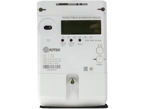
Счетчики электрической энергии однофазные многофункциональные РОТЕК РТМ-01 (далее — счетчики) предназначены для измерений активной и реактивной электрической энергии прямого или обратного направления по дифференцированным во времени тарифам в однофазных сетях переменного тока промышленной частоты.
Информация по Госреестру
| Основные данные | |
|---|---|
| Номер по Госреестру | 77307-20 |
| Наименование | Счетчики электрической энергии однофазные многофункциональные |
| Модель | РОТЕК РТМ-01 |
| Межповерочный интервал / Периодичность поверки | 16 лет |
| Страна-производитель | РОССИЯ |
| Срок свидетельства (Или заводской номер) | 30.01.2025 |
Производитель / Заявитель
АО «НПК РоТеК», г.Москва
Назначение
Счетчики электрической энергии однофазные многофункциональные РОТЕК РТМ-01 (далее — счетчики) предназначены для измерений активной и реактивной электрической энергии прямого или обратного направления по дифференцированным во времени тарифам в однофазных сетях переменного тока промышленной частоты.
Описание
Принцип действия счетчиков основан на вычислении действующих значений тока и напряжения, активной энергии, мощности, коэффициента мощности и частоты сети переменного тока по измеренным мгновенным значениям входных сигналов тока и напряжения. Счетчики также обеспечивают отсчет времени, календарной даты и вывод данных на жидкокристаллический индикатор (ЖКИ).
Счетчики могут использоваться как автономно, так и в автоматизированных информационно-измерительных системах учета электрической энергии для передачи измерительных или вычислительных параметров на диспетчерский пункт по контролю, учету и распределению электрической энергии.
Счетчики имеют в своем составе датчики тока и напряжения, внутренние часы специальный измерительный преобразователь, микроконтроллер, энергонезависимую память, источник питания, жидкокристаллический индикатор для просмотра информации, кнопки управления, световые индикаторы, интерфейс RS-485, ИК-порт, оснащены отключающим реле. В счетчики дополнительно могут устанавливаться взаимозаменяемые блоки ввода-передачи данных.
Конструктивно счетчик выполнен в пластмассовом корпусе. Конструкция счетчика соответствует требованиям ГОСТ 31818.11-2012. Основные клеммы счетчика, предназначенные для подключения к электрической сети, выполнены из электротехнического сплава. Дополнительные контакты клеммной колодки предназначены для импульсных выходов и цифровых интерфейсов. На передней панели счетчика расположена кнопка управления режимами индикации дисплея.
Токи и напряжения измеряемой сети через соответствующие зажимы и входные элементы поступают на соответствующие входы измерительного преобразователя, который выполняет преобразование аналоговых сигналов напряжения и тока в цифровые значения этих величин.
Центральный процессор принимает результаты измерений и размещает их в энергонезависимой памяти, поддерживает связь через интерфейс RS-485, ИК-порт, оптопорт, дополнительный блок ввода-передачи данных и выводит информацию на дисплей.
Измеренные данные, параметры конфигурации, статусная и иная информация хранятся в энергонезависимой памяти и могут отображаться на жидкокристаллическом индикаторе счетчика.
С помощью программного обеспечения возможно осуществление настройки параметров счетчика, а также считывание данных, при этом связь компьютера со счетчиком может осуществляться как через оптический, так и цифровой порт. Для осуществления мер безопасности и надежности перед настройкой параметров счетчика необходимо пройти процедуру идентификации.
Фотография общего вида счетчиков, с указанием схем пломбировки от несанкционированного доступа, приведены на рисунках 1-4.
Структура условного обозначения Счетчик электрической энергии однофазный многофункциональный РОТЕК РТМ-01_
D — для установки на DIN-рейку
B — для установки на щиток
С — для установки на опору_
Напряжение и сила тока
A — класс точности 2 по ГОСТ 31819.21-2012 B — класс точности 1 ГОСТ 31819.21-2012 C — класс точности 2 по ГОСТ 31819.21-2012, класс точности 2 по ГОСТ 31819.23-2012
D — класс точности 1 по ГОСТ 31819.21-2012, класс точности 2 по ГОСТ 31819.23-2012
F — класс точности 2 по ГОСТ 31819.21-2012, класс точности 1 по ГОСТ 31819.23-2012
G — класс точности 1 по ГОСТ 31819.21-2012, класс точности 1 по ГОСТ 31819.23-2012
Читайте также:
- Как зайти в пинтерест через компьютер
- Самый выгодный ноутбук 2020
- Как сделать панорамный скриншот на компьютере
- Метод анализа иерархий выбор компьютера
- Не работает pci lpt контроллер
IRM-U06ID RDU-A Intelligent Monitoring Unit
User Manual
Version V2.3
Revision date July 24, 2012
BOM 31012629
Emerson Network Power provides customers with technical support. Users may contact the nearest
Emerson local sales office or service center.
Copyright © 2012 by Emerson Network Power Co., Ltd.
All rights reserved. The contents in this document are subject to change without notice.
Emerson Network Power Co., Ltd.
Address: No.1 Kefa Rd., Science & Industry Park, Nanshan District 518057, Shenzhen China
Homepage: www.emersonnetworkpower.com.cn
E-mail: [email protected]
Contents
Chapter 1 Introduction ……………………………………………………………………………………………………………………………………… 1
1.1 Characteristics …………………………………………………………………………………………………………………………………… 1
1.2 Component Descriptions ……………………………………………………………………………………………………………………… 1
1.2.1 RDU-A Host …………………………………………………………………………………………………………………………….. 1
1.2.2 Power Module ………………………………………………………………………………………………………………………….. 4
1.2.3 IRM-E04COM Board (Optional) ………………………………………………………………………………………………….. 5
1.3 Main Functions…………………………………………………………………………………………………………………………………… 5
1.4 Technical Specifications ……………………………………………………………………………………………………………………… 6
1.4.1 Safety Regulations And EMC …………………………………………………………………………………………………….. 6
1.4.2 Environment Specifications ……………………………………………………………………………………………………….. 6
1.4.3 Mechanical Specifications …………………………………………………………………………………………………………. 7
1.4.4 Performance Specifications ……………………………………………………………………………………………………….. 7
Chapter 2 Hardware Installation ………………………………………………………………………………………………………………………… 8
2.1 Installation Preparation ……………………………………………………………………………………………………………………….. 8
2.1.1 Note ……………………………………………………………………………………………………………………………………….. 8
2.1.2 Environmental Requirement ………………………………………………………………………………………………………. 8
2.1.3 Heat Dissipation Requirement ……………………………………………………………………………………………………. 8
2.1.4 Installation Tool ……………………………………………………………………………………………………………………….. 8
2.2 Installing IRM-E04COM Board ……………………………………………………………………………………………………………… 9
2.2.1 Set Communication Mode Of COM5 ~ COM8 ………………………………………………………………………………. 9
2.2.2 Mechanical Installation ……………………………………………………………………………………………………………… 9
2.3 Installing RDU-A Host And Power Module ……………………………………………………………………………………………… 9
2.3.1 Set Communication Mode Of COM1 ~ COM3 ………………………………………………………………………………. 9
2.3.2 Mechanical Installation ……………………………………………………………………………………………………………. 10
2.3.3 Electrical Connection ………………………………………………………………………………………………………………. 12
2.4 Installing Sensor ………………………………………………………………………………………………………………………………. 12
2.4.1 Installing Intelligent Sensors …………………………………………………………………………………………………….. 12
2.4.2 Installing Physical Sensors ………………………………………………………………………………………………………. 14
Chapter 3 Access RDU-A Through Interfaces ……………………………………………………………………………………………………. 15
3.1 Logging On RDU-A …………………………………………………………………………………………………………………………… 15
3.1.1 Through Network Port (LAN) ……………………………………………………………………………………………………. 15
3.1.2 Through Console Port (CONSOLE) …………………………………………………………………………………………… 17
3.2 Power On RDU-A ……………………………………………………………………………………………………………………………… 19
3.3 Using Command Line ……………………………………………………………………………………………………………………….. 19
3.3.1 Logging On To The Command Line ………………………………………………………………………………………….. 19
3.3.2 Setting RDU-A User Password …………………………………………………………………………………………………. 19
3.3.3 Setting IP Address Of RDU-A …………………………………………………………………………………………………… 19
3.3.4 Set Time Of RDU-A ………………………………………………………………………………………………………………… 20
3.3.5 Reboot RDU-A ……………………………………………………………………………………………………………………….. 20
Chapter 4 Access RDU-A Through Web …………………………………………………………………………………………………………… 21
4.1 Overview Of Web Function ………………………………………………………………………………………………………………… 21
4.2 Authorizing Boot-Strap Page………………………………………………………………………………………………………………. 21
4.3 Login RDU-A Web Page ……………………………………………………………………………………………………………………. 22
4.4 Getting Password Page …………………………………………………………………………………………………………………….. 23
4.5 RDU-A Homepage ……………………………………………………………………………………………………………………………. 23
4.6 Menu ………………………………………………………………………………………………………………………………………………. 24
4.6.1 Data Center …………………………………………………………………………………………………………………………… 24
4.6.2 AC TeamWork ……………………………………………………………………………………………………………………….. 30
4.6.3 Alarm Options ………………………………………………………………………………………………………………………… 34
4.6.4 Data & History ……………………………………………………………………………………………………………………….. 41
4.6.5 Device Options ………………………………………………………………………………………………………………………. 42
4.6.6 System Options ……………………………………………………………………………………………………………………… 48
4.6.7 Personal Setting …………………………………………………………………………………………………………………….. 55
4.7 Shortcut Method ……………………………………………………………………………………………………………………………….. 56
4.7.1 Modifying Signal Name ……………………………………………………………………………………………………………. 57
4.7.2 [User] Logout …………………………………………………………………………………………………………………………. 57
4.7.3 Controllable Status …………………………………………………………………………………………………………………. 57
4.7.4 Time Calibration Link ………………………………………………………………………………………………………………. 58
4.7.5 View By Location ……………………………………………………………………………………………………………………. 58
Chapter 5 RDU-A Configuration ………………………………………………………………………………………………………………………. 60
5.1 RDU-A Configuration Method …………………………………………………………………………………………………………….. 60
5.2 RDU-A Configuration Demonstration …………………………………………………………………………………………………… 61
Chapter 6 Maintenance ………………………………………………………………………………………………………………………………….. 65
6.1 Recovering Default Setting ………………………………………………………………………………………………………………… 65
6.2 FAQ ……………………………………………………………………………………………………………………………………………….. 65
Appendix 1 Abbreviation ………………………………………………………………………………………………………………………………… 72
Appendix 2 Standard Configuration List ……………………………………………………………………………………………………………. 73
Chapter 1 Introduction 1
Chapter 1 Introduction
IRM-U061D RDU-A intelligent monitoring unit (RDU-A for short) supplies flexible monitoring solutions for data centers.
This chapter expounds characteristics, component descriptions, main functions and technical specifications of
RDU-A.
1.1 Characteristics
RDU-A has the following characteristics:
Supporting connection of intelligent sensor modules from our company
Supporting connection of equipment from our company and third party for extension
Supporting online adding, deleting and modifying equipment
Supplying notifying function of alarm in real time, and reminding users timely
Supporting SNMP protocol to connect intelligent equipment for extension
Having simple programmable logic controller function to map alarms
Supporting remote service function
Supporting AC teamwork function
1.2 Component Descriptions
RDU-A includes RDU-A host, power module IRM-U061DR1 (power module for short) and IRM-E04COM board
(optional).
1.2.1 RDU-A Host
The appearance and interfaces of RDU-A host are shown in Figure 1-1.
Power indicator
Alarm indicator
Front view
IRM-U061D RDU-A Intelligent Monitoring Unit User Manual
2 Chapter 1 Introduction
17
16
10
11
12 13
14
15
9
1
8
7
6
5
4
3
2
2.PE 3.Power port 4.Network port
7.Relay output port 2 8.Relay output port 1 9.Expansion slot
5.Console port
10.Door status 1 port
1.Indicators
6.USB port
11.Door status 2 port 12.Smoke port
16.COM 1 17.Water port
13.Sensor port 14.COM 2
Rear view
Figure 1-1 Appearance and interface
15.COM 3
Indicators
There are two indicators on the front panel of the RDU-A host, as shown in Figure 1-1. See Table 1-1 for their definitions.
Table 1-1 Definition of Indicators in the front panel
Silk print
POWER
ALARM
Definition
Power indicator
Alarm indicator
Color
Green
Red
On
Off
On
Status Definition
The RDU-A host is powered on
The RDU-A host is powered off
Critical alarm
Off No alarm
Blinking slowly (about 0.5Hz) Observation alarm
Blinking quickly (about 4Hz) Major alarm
There are nine indicators on the rear panel of the RDU-A host, of which two indicators are reserved. Their positions are shown in Figure 1-1. See Table 1-2 for their definitions.
Silk print
POWER
ALARM
SLOT
SENSOR
COM1 ~ COM3
Definition
Power indicator
Alarm indicator
Slot indicator
Sensor port indicator
COM port indicator
Table 1-2 Definition of Indicators in the rear panel
Color
Green
Red
Green
Green
Green
On
Off
On
Off
Status
Blinking slowly (about 0.5Hz) Observation alarm
Blinking quickly (about 4Hz)
On
Off
Blinking quickly (about 4Hz)
Blinking
Off
Blinking
Off
The RDU-A host is powered on
The RDU-A host is powered off
Critical alarm
No alarm
Major alarm
Definition
The board inside the slot is normal
No board is inside the slot or the inside board is abnormal
Detecting the board status automatically while starting up
Data received and sent
No data received or sent
Data received and sent
No data received or sent
IRM-U061D RDU-A Intelligent Monitoring Unit User Manual
Chapter 1 Introduction 3
Network port
The RDU-A host supplies a network port, which adopts 10/100M self-adaptable Ethernet port. Its position is shown in
Figure 1-1.
Console port
The RDU-A host supplies a console port (RJ45 interface, see Figure 1-1 for its position), which adopts RS-232C communication mode. The communication parameters are given in Table 1-3.
Parameter
Value
USB port
Table 1-3 Communication parameters of console port
Baud rate
115200bps
Bit
8 bits
Parity
None
Stop bit
1 bit
The RDU-A host supplies a USB port for connecting camera or USB Modem of designated model. Its position is shown in Figure 1-1.
Relay output port
The RDU-A host supplies two relay outputs. Their positions are shown in Figure 1-1. See Table 1-4 for their parameters and Table 1-5 for phase sequences of the RJ45 interface.
Table 1-4 Relay output port parameter
Parameter
Route
Output contact
Contact capability
Value
2
Relay output contact
(normally-open/normally-closed optional)
0.75A/30Vdc
Description
Two relays can be controlled independently, totally supplying +24Vdc/0.2A power output
Table 1-5 Phase sequences of relay output port (RJ45 interface)
Phase sequence
1
Definition
1
24V
2
24V
3
Normallyclosed
4
GND
5
Common end
6
Normallyopen
Note:
1. The phase sequences of RJ45 interface are 1 to 8 from left to right, with the gap downwords;
2. NC: Not Connected
Digital signal port
7
NC
2
8
NC
The RDU-A host supplies four digital signal ports. Their positions are shown in Figure 1-1. See Table 1-6 for their parameters and Table 1-7 for phase sequences of the RJ45 interface.
Table 1-6 Digital signal port parameter
Silk print Definition Interface type Measured signal Power output
Maximum output current
DOOR1
DOOR2
WATER
Door status 1 port
Door status 2 port
Water port
RJ45 interface Dry contact + 24Vdc
0.4A (the total current of 4 inputs)
SMOKE Smoke port
Note: These ports are all default configurations, which can also be configured as other sensor
’s connecting mode through software configuration by maintenance engineers only
Phase sequence
Definition
1
24V- signal input+
Table 1-7 Phase sequences of digital signal port (RJ45 interface)
2
24V- signal input+
3
Signal input-
(GND)
4
GND
5
GND
6
Signal input-
(GND)
7
Signal input-
(GND)
8
Signal input-
(GND)
IRM-U061D RDU-A Intelligent Monitoring Unit User Manual
4 Chapter 1 Introduction
Sensor port
The RDU-A host supplies a route of sensor port, including two RJ45 interfaces. Their positions are shown in
Figure 1-1.
Adopt RS-485 communication mode, see Table 1-8 for its communication parameters
Parameter
Value
Table 1-8 Communication parameters of sensor port
Baud rate
9600bps
Bit
8 bits
Parity
None
Stop bit
1 bit
Dedicated interface for temperature & humidity sensor, temperature sensor and digital expansion module
Supply 24Vdc for connected sensor
Up to 25 sensors can be connected
COM port
The RDU-A host supplies three independent COM port, namely, COM1, COM2 and COM3. Their positions are shown in Figure 1-1.
Their communication modes are all RS-485/RS-232C, which can be chosen by jumper settings. See Table 1-9 and Table 1-10 for their communication parameters and phase sequences of the RJ45 interface.
Parameter
Value
Table 1-9 Communication parameters of COM port
Baud rate
1200bps, 2400bps,
4800bps, 9600bps,
19200bps (optional)
Bit
6 ~ 8 bits
Parity
Even/Odd/None
Phase sequence
Definition
1
RTS
Table 1-10 Phase sequences of COM port (RJ45 interface)
2
NC
3
TXD
4
GND
5
GND
6
RXD
Isolated from each other, not hot-pluggable
7
D+
Stop bit
1 ~ 2 bits
8
D-
1.2.2 Power Module
The RDU-A has a dedicated power module. Its appearance is shown in Figure 1-2.
Figure 1-2 Power module
The power module can only be used for RDU-A products. Its AC end adopts common power cable, the input voltage is 100Vac ~ 250Vac and the input frequency is 45Hz ~ 65Hz; its DC end adopts Phoenix terminal. The power module supplies two DC outputs, and the output voltage is 24Vdc. Its total power is 30W.
Note
It is prohibited to open the shell of the power module.
IRM-U061D RDU-A Intelligent Monitoring Unit User Manual
Chapter 1 Introduction 5
1.2.3 IRM-E04COM Board (Optional)
IRM-E04COM board supplies four COM ports (COM5 ~COM8), which are used to connect user equipment. Its appearance is shown in Figure 1-3.
Jumper J9 ~ J11
Jumper J13 ~ J15
Jumper J5 ~ J7
Jumper J1 ~ J3
Indicator
COM5 ~ COM8
Figure 1-3 IRM-E04COM board
See Table 1-11 for the indicator definitions of IRM-E04COM board.
Silk print
POWER
COM5 ~ COM8
Definition
COM port indicator
Table 1-11 Indicator definitions of IRM-E04COM board
Power indicator
Color
Green
Green
Status
On
Off
Blinking
Off
Description
The IRM-E04COM board is powered on
The IRM-E04COM board is powered off
Data received and sent
No data received or sent
1.3 Main Functions
The main functions of RDU-A are listed in Table 1-12.
Main function
Device monitoring
AC TeamWork
Alarm Options
Table 1-12 Main functions of RDU-A
Description
Realizing camera viewing in data center; getting and handling the data of different intelligent devices and controlling them through Web interface
Monitoring and controlling each AC which participates in the AC teamwork according to a certain rule, to achieve the goals of reducing AC power consumption, prolonging AC life-span and avoiding competition among ACs in the team
Current alarm Displaying alarm in real time, and confirming the current alarm
History alarm Querying the history alarm
Alarm notification
Actions
1. Can be customized according to user requirements, that is, alarm notification content can be customized;
2. You can choose the communication mode to receive alarm information of different level from different equipment;
3. The communication mode includes Email, SMS and phone;
4. Email supports SSL function;
5. Supplying alarm test function to test whether or not users have received the alarm notification information;
6. Sending the system running status periodically according to user configuration
1. Can be customized according to user requirements;
2. REKAY1 alarm output;
3. Can combine equipment signals, parameters and alarm to control equipment;
4. Having the following logic components:
1) AND, which represent AND command 2) OR, which represent OR command
3) NOT, which represent NOT command 4) XOR, which represent XOR command
5) GT, which represent GT command
7) DS, which represent DS command
6) LT, which represent LT command
IRM-U061D RDU-A Intelligent Monitoring Unit User Manual
6 Chapter 1 Introduction
Main function
Data & History
Device Options
System Options
Personal Setting
Description
Device information
History data
History log
Clear history
Device management
Querying the main data of equipment
Querying the history data
Querying the log data
Clearing the history data and log data
1. Can add, modify and delete equipment actively, and support adding seven pieces of intelligent equipment at most;
2. Can install and uninstall equipment type and support connecting third party equipment
Modifying equipment name, signal name and alarm level online Signal setting
Batch configuration
Monitoring unit
Updating and downloading configuration files and system files
Network setting
Collecting the system information of RDU-A
1. Setting the network information such as IP, subnet mask, gateway and DNS;
2. Controlling whether the upper monitoring system (RDU-M manager) can visit the
RDU-A;
3. Remote service setting
User management Adding, modifying and deleting user information
Date/time setting Calibrating the real time clock of RDU-A
System reset Rebooting the RDU-A and restoring default configuration
Site setting
System upgrade
System title
Status bar
Modifying site information online
Upgrading the application program online
Setting title and logo picture at the top of the Web page
Configuring the current display contents of the status bar
1.4 Technical Specifications
1.4.1 Safety Regulations And EMC
See Table 1-13 for the safety regulations and EMC of RDU-A.
Safety regulations
EMC
Item
Table 1-13 Safety regulations and EMC
Description
EN60950, UL60950 (CE)
EN 55022:2006, IEC61000-4-6: 2006
1.4.2 Environment Specifications
See Table 1-14 for the environment specifications of RDU-A.
Item
Application location
Working temperature
Relative humidity
Working environment
Air pressure
Storage temperature
Cooling
Power distribution network
Protection level
Table 1-14 Environment conditions
Requirement
Usually in data center or computer room, with air conditioner
-10ºC ~ +50ºC
5%RH ~ 95%RH, no condensing
Dust: compliant with the indoor requirements of GR-63. No corrosive gas, flammable gas, oily mist, steam, water drops or salt
70kpa ~ 106kpa
-40ºC ~ +70ºC
Natural cooling
TT/TN
IP20
IRM-U061D RDU-A Intelligent Monitoring Unit User Manual
Chapter 1 Introduction 7
1.4.3 Mechanical Specifications
See Table 1-15 for the mechanical specifications of RDU-A.
Components
RDU-A host
Power module
IRM-E04COM board
Table 1-15 Mechanical specifications
Size (L × W × H, unit: mm)
483.0 × 286.0 × 40.3
198.2 × 108.0 × 42.6
122.0 × 180.0 × 20.0
1.4.4 Performance Specifications
Weight (unit: kg)
≤ 5
≤ 1
≤ 0.5
See Table 1-16 for the performance specifications of RDU-A.
Table 1-16 Performance specifications
Connected component Cable standard Connected distance (unit: m)
Connected number / connection point
Connecting nodes of DI,
SENSOR ports
Acousto-optic alarm indicator
Standard category 4 twisted-pair cable
Standard category 4 twisted-pair cable
≤ 100
≤ 100
28
2
[1]
[2]
Intelligent device
Standard category 4 twisted-pair cable
≤ 100
16
[3]
Note:
[1]: For temperature, temperature and humidity, door status, water, 4DI, 4DO sensors, DO devices and so on, each sensor or device is calculated as one node; for smoke and infrared sensors, each sensor is calculated as four nodes;
[2]: The acousto-optic alarm indicator has two routs of connection points: RELAY1, RELAY2, which can be used as two routes of digital output for other use;
[3]: The RDU-A can connect up to 16 intelligent devices, not including the default devices. The devices connected through network mode cannot exceed eight, and the connected devices of single COM cascade cannot exceed four
IRM-U061D RDU-A Intelligent Monitoring Unit User Manual
8 Chapter 2 Hardware Installation
Chapter 2 Hardware Installation
This chapter introduces the hardware installation of RDU-A, including installation preparation, installing IRM-E04COM board, installing RDU-A host and power module and installing sensor.
2.1 Installation Preparation
2.1.1 Note
To ensure the safety of the product and installation personnel, take the following precautions:
Always cut off the power before performing any installation operation
Ensure that the peripheral equipment are connected to the correct RDU-A ports
The IRM-E04COM board is not hot-pluggable, if it is plugged into the serial port when power is on, it cannot work normally
Wear an ESD wrist-wrap when installing the IMU6100
Arrange the wires properly, and do not put any heavy objects on the wires or stamp the wires
2.1.2 Environmental Requirement
Operating environment
The RDU-A must be installed indoors. See Table 1-14 for the detailed requirements.
Anti-static requirement
Take the following measures for minimizing static influences:
Maintain proper temperature and humidity in the room (See Table 1-14)
Wear antistatic clothing and an ESD wrist-wrap when operating the RDU-A; if antistatic clothing or ESD wrist-wraps are unavailable, wash your hands and dry them instead, which helps discharge the static electricity
Anti-EMI requirement
Take the following measures for anti-EMI purpose:
Do not connect the RDU-A working ground to the working ground or lightning ground of electrical power equipment. Instead, place them away from each other as far as possible
Keep the RDU-A away from large-power radio transmitter, radar, or high-frequency large current electrical equipment
Use electromagnetic shielding if necessary
2.1.3 Heat Dissipation Requirement
Keep the RDU-A as far as possible from heat sources
It is recommended to install the RDU-A into a 19 ’’ standard cabinet. Keep at least 10mm clearance around the
RDU-A for heat dissipation
2.1.4 Installation Tool
The required installation tools are listed in Table 2-1.
Tool
Cross screwdriver
Digital multimeter
Table 2-1 Installation tools
Specification
100mm, 200mm
3.5-bit digital display
Usage
Installing the brackets, top cover and dummy plate for expansion slot of RDU-A host, and pothook of power module
Inspecting the electrical connection
IRM-U061D RDU-A Intelligent Monitoring Unit User Manual
Chapter 2 Hardware Installation 9
2.2 Installing IRM-E04COM Board
Note
The IRM-E04COM board is optional, and you can choose whether to buy and install it or not.
Before installing the IRM-E04COM board, users need to set communication mode of COM5 ~ COM8 first, and then perform the mechanical installation.
2.2.1 Set Communication Mode Of COM5 ~ COM8
Serial ports COM5 ~ COM8 all have two optional modes: RS-485/RS-232C. Different COM ports can be set through different jumpers. COM5: J13 ~ J15; COM6: J9 ~ J11; COM7: J5 ~ J7; COM8: J1 ~ J3. The interfaces and jumpers of the IRM-E04COM board are shown in Figure 2-1.
Jumper J9 ~ J11 amplified
Jumper J9 ~ J11
Jumper J13 ~ J15
Jumper J5 ~ J7
Jumper J1 ~ J3
Jumper J5 ~ J7 amplified
Jumper J13 ~ J15 amplified
Indicators
COM5 ~ COM8
Figure 2-1 Interfaces and jumpers of the IRM-E04COM board
See Table 2-2 for the jumper settings of IRM-E04COM board.
COM port
COM5
COM6
COM7
COM8
Table 2-2 Jumper setting of IRM-E04COM board
Jumper
J13/J14/J15
J9/J10/J11
J5/J6/J7
J1/J2/J3
Short connect pin1 and pin2
RS-485
RS-485
RS-485
RS-485
Short connect pin2 and pin3
RS-232C
RS-232C
RS-232C
RS-232C
Jumper J1 ~ J3 amplified
Default
RS-485
RS-485
RS-485
RS-485
2.2.2 Mechanical Installation
1. Remove the dummy plate on the back panel of the RDU-A host, and reserve it for future use.
2. Insert the IRM-E04COM board into the expansion slot and screw the two bolts on both sides of the panel.
3. Ensure that the POWER indicator on the IRM-E04COM board is on, and it is green in normal condition. If the
POWER indicator is off, refer to Q3 in 6.2 FAQ.
2.3 Installing RDU-A Host And Power Module
Before installing the RDU-A host, users need to set communication mode of COM1 ~ COM3 first, and then perform the mechanical installation and electrical connection.
2.3.1 Set Communication Mode Of COM1 ~ COM3
Serial ports COM1 ~ COM3 all have two optional modes: RS-485/RS-232C. Different COM ports can be set through different jumpers. COM1: J21 ~ J23; COM2: J25, J26; COM3: J27, J28. The jumper positions are shown in
Figure 2-2.
IRM-U061D RDU-A Intelligent Monitoring Unit User Manual
10 Chapter 2 Hardware Installation
Jumper J21 ~ J23, J25 ~ J28 amplified
Jumper J21 ~ J23, J25 ~ J28
Figure 2-2 Jumpers J21 ~ J23, J25 ~ J28
See Table 2-3 for the communication mode settings of serial port COM1 ~ COM3.
COM port
COM1
COM2
COM3
Table 2-3 Set the communication mode of COM1 ~ COM3
Jumper
J21, J22, J23
J25, J26
J27, J28
Short connect pin1 and pin2
RS-485
RS-485
RS-485
Short connect pin2 and pin3
RS-232C
RS-232C
RS-232C
2.3.2 Mechanical Installation
Default
RS-232C
RS-485
RS-485
The RDU-A host and power module can be installed in a rack.
The installation procedures are as follows:
1. Confirm that the rack has been secured, with no obstacles inside or outside the rack.
2. Fasten the hangers to the two sides of the RDU-A host with accessory M4 bolts, as shown in Figure 2-3.
M4 screw (6 pcs)
Installation hole (6 pcs)
Bracket (2 pcs)
Figure 2-3 Fixing hangers
The hangers are installed, as shown in Figure 2-4.
Figure 2-4 Hangers of RDU-A host are installed
3. Put the RDU-A host on the rails on both sides of the rack, and push it into the rack completely, as shown in
Figure 2-5.
IRM-U061D RDU-A Intelligent Monitoring Unit User Manual
Chapter 2 Hardware Installation 11
Figure 2-5 Pushing RDU-A host into rack
4. Use M6 floating nuts to fasten the hangers of RDU-A host to the rack.
5. Use accessory tapping screws (ST2.9 × 6.5F) to fasten pothook to the back installation hole of the power module, as shown in Figure 2-6.
Installation hole
(2 pcs)
Pothook
Tapping screw
(2 pcs)
Figure 2-6 Installing pothook of RDU-A host
The pothook is installed, as shown in Figure 2-7. Then hang the power module IRM-U061DR1 in the square holes of rack’s vertical poles or crossbeams.
Note
1. If the rack’s top cover has a cable entry hole, the power module can only be hung in the square holes of the back vertical poles, to avoid metal objects such as cables and screws from entering the power module through the cable entry hole.
2. The power module can also be placed on the RDU-A host or other equipment flatwise.
Figure 2-7 Pothook is installed
IRM-U061D RDU-A Intelligent Monitoring Unit User Manual
12 Chapter 2 Hardware Installation
2.3.3 Electrical Connection
The electrical connection procedures of the RDU-A host and power module are as follows:
1. Use earth cable to connect the PE (as shown in Figure 1-1) on the RDU-A host.
2. Insert the terminal of power module
’s output cable into the power interface (as shown in Figure 1-1) of the RDU-A host.
3. Ensure that the wiring is correct. Connect the power input terminal to the mains supply.
2.4 Installing Sensor
RDU-A can connect intelligent sensors and physical sensors.
2.4.1 Installing Intelligent Sensors
The intelligent sensors include: IRM-S01T intelligent temperature sensor (IRM-S01T for short), IRM-S02TH intelligent temperature and humidity sensor (IRM-S02TH for short), IRM-S04DI intelligent digital input sensor with Phoenix ports
(IRM-S04DI for short), IRM-S04DIF intelligent digital input sensor with RJ45 ports (IRM-S04DIF for short). Their appearances are shown in Figure 2-8.
IRM-S01T IRM-S02TH
IRM-S04DI IRM-S04DIF
Figure 2-8 Intelligent sensors
Environment requirement
Operating environment should be electric dust free, corrosive metal free and insulation breakdown gas free.
Avoid using the sensor in watery or foggy places.
Operating temperature: -10°C ~ +50°C; Storage temperature: -30°C ~ +70°C; Humidity: 5% ~ 95% (non-condensing).
Installation requirement
Keep a clearance of more than 20mm around the sensor’s airway to ensure ventilation inside and outside of the sensor.
Installation procedures
For the installation procedures of the intelligent sensors, refer to the corresponding intelligent sensor user manuals:
Refer to IRM-S01T Intelligent Temperature Sensor User Manual for IRM-S01T;
IRM-U061D RDU-A Intelligent Monitoring Unit User Manual
Chapter 2 Hardware Installation 13
Refer to IRM-S02TH Intelligent Temperature And Humidity Sensor User Manual for IRM-S02TH;
Refer to IRM-S04DI Intelligent Digital Input Sensor With Phoenix Ports User Manual for IRM-S04DI;
Refer to IRM-S04DIF Intelligent Digital Input Sensor With RJ45 Ports User Manual for IRM-S04DIF.
Address setting
The intelligent sensor address is composed of group number and serial number in the group, which can be set through the DIP switch on the intelligent sensor.
The address setting methods of IRM-S01T and IRM-S02TH are the same. The address is set through DIP switch
DIP1 ~ DIP6, among which DIP1 ~ DIP4 are used to set the group number and DIP5 ~ DIP6 are used to set the serial number within the group. For example, the sensor address of 71 is set as shown in Figure 2-9, among which
0111 means group number 7 and 01 means serial number 1 within the group.
0 1 1 1 0 1
1 2 3 4 5 6
DIP ON
Note: 1. DIP switch in the ON position means 1,
or it means 0;
2. The sensor address cannot be set as 00, which is the broadcast address.
Group Num
Figure 2-9 DIP switch setting schematic diagram
The settings of DIP1 ~ DIP6 are listed in the Table 2-4.
Table 2-4 DIP1 ~ DIP6 setting table
DIP1 ~ DIP4
0 0 0 0
0 0 0 1
0 0 1 0
0 0 1 1
0 1 0 0
0 1 0 1
Group
0
1
2
3
4
5
DIP1 ~ DIP4
0 1 1 0
0 1 1 1
1 0 0 0
1 0 0 1
1 0 1 0
1 0 1 1
Group
6
7
8
9
A b
DIP1 ~ DIP4
1 1 0 0
1 1 0 1
1 1 1 0
1 1 1 1
Group
C d
E
F
DIP5 ~ DIP6 Number
0 0
0 1
1 0
0
1
2
1 1 3
The address setting methods of IRM-S04DI intelligent digital input sensor with Phoenix ports and IRM-S04DIF intelligent digital input sensor with RJ45 ports are the same. The address is set through DIP switch DIP1 ~ DIP6, among which DIP1 ~ DIP4 are used to set the group number; DIP5 is used to set the serial number within the group;
DIP6 is used to set the type of connected equipment. For example, the sensor address of 70 is set as shown in
Figure 2-10, among which 0111 means group number 7; 0 means serial number 0 within the group and 1 means that the type of connected equipment is user customized equipment.
0 1 1 1 0 1
1 2 3 4 5 6
DIP ON
Group Num
Note: 1. DIP switch in the ON position means 1,
or it means 0;
2. The sensor address cannot be set as 00, which is the broadcast address.
OFF: Fixed
ON: User
Figure 2-10 DIP switch setting schematic diagram
The settings of DIP1 ~ DIP4 are listed in the Table 2-5.
DIP1 ~ DIP4
0 0 0 0
0 0 0 1
0 0 1 0
0 0 1 1
Group
0
1
2
3
Table 2-5 DIP1 ~ DIP4 setting table
DIP1 ~ DIP4
0 1 0 0
0 1 0 1
0 1 1 0
0 1 1 1
Group
4
5
6
7
The settings of DIP5, DIP6 are listed in the Table 2-6.
DIP1 ~ DIP4
1 0 0 0
1 0 0 1
1 0 1 0
1 0 1 1
DIP5
0
1
Table 2-6 DIP5, DIP6 setting table
Number
0
1
DIP6
0
1
Group
8
9
A b
DIP1 ~ DIP4
1 1 0 0
1 1 0 1
1 1 1 0
1 1 1 1
Connected equipment type
Fixed equipment
User customized equipment
Group
C d
E
F
IRM-U061D RDU-A Intelligent Monitoring Unit User Manual
14 Chapter 2 Hardware Installation
2.4.2 Installing Physical Sensors
The physical sensors include smoke sensor, water sensor and door status sensor.
Installing smoke sensor
The smoke sensor is used for fire detection during preliminary fire brewing stage when plenty of smog is generated.
You can choose whether or not to buy and install it on their own.
1. Environment requirement
The smoke sensor should not be installed where:
The relative humidity often exceeds 95%RH
The air flow speed exceeds 5m/s
Plenty of dust, thick fog, or corrosive gas is present
Alcohol, aether, or ketone type organic substances are present
2. Installation requirement
The smoke sensor should be installed in the center of the ceiling.
0.5m clearance should be maintained around the smoke sensor; the smoke sensor should be installed at least 1.5m away from the air vent of the air conditioner, and at least 0.5m away from the air vent of the ceiling.
3. Installation procedure
The smoke sensor has two installation modes:
Directly connected to the smoke port (silk print: SMOKE) on the RDU-A rear panel, see Table 1-7 for the phase sequences
Connected to RDU-A through IRM-S04DI or IRM-S04DIF: connect the smoke sensor to the digital signal port of
IRM-S04DI or IRM-S04DIF, refer to IRM-S04DI Intelligent Digital Input Sensor With Phoenix Ports User Manual for IRM-S04DI or IRM-S04DIF Intelligent Digital Input Sensor With RJ45 Ports User Manual for IRM-S04DIF for the phase sequences
Installing water sensor
You can choose whether or not to buy and install the water sensor on their own.
The water sensor should be horizontally positioned at a low place or in front of the communication equipment.
For the installation procedures of water sensor, refer to Installing smoke sensor.
Installing door status sensor
You can choose whether or not to buy and install the door status sensor on their own.
When the door is closed, only a maximum of 5mm distance is allowed between the two parts of the door status sensor. If the distance exceeds 5mm, find a proper position for the sensor to meet the requirement.
For the installation procedures of door status sensor, refer to Installing smoke sensor.
IRM-U061D RDU-A Intelligent Monitoring Unit User Manual
Chapter 3 Access RDU-A Through Interfaces 15
Chapter 3 Access RDU-A Through Interfaces
This chapter expounds how to access RDU-A through interfaces, including logging on RDU-A, power on RDU-A and using command line.
3.1 Logging On RDU-A
3.1.1 Through Network Port (LAN)
1. Use a standard network cable to connect the network port of the RDU-A host with the network port of the computer.
2. You should set the parameters of HyperTerminal after the network cable is connected. The detailed setting procedures are as follows:
Step 1: First open the console panel in PC, double click the icon of Network Connections, and then double click
Local Area Connection to enter network configuration dialog box as shown in Figure 3-1. Click Properties to open
Local Area Connection Properties dialog box, and then double click Internet Protocol (TCP/IP) to configure the IP address. The recommended configuration is
‘192.168.0.1’, as shown in Figure 3-2.
Figure 3-1 Local area connection properties
IRM-U061D RDU-A Intelligent Monitoring Unit User Manual
16 Chapter 3 Access RDU-A Through Interfaces
Figure 3-2 Internet protocol (TCP/IP) properties
Step 2: Click Start -> Programs -> Accessories -> Communications -> HyperTerminal, the HyperTerminal interface as shown in the Figure 3-3 pops up. Type the name
‘RDU-A’ in the Name field and click OK.
RDU-A
Figure 3-3 HyperTerminal
Step 3: Select TCP/IP as the connection mode and click OK, as shown in Figure 3-4.
RDU-A
Enter details for the phone number that you want to dial:
Country/region:
China(86)
Area code:
Phone number:
029
Connect using:
OK
Cancle
Figure 3-4 Communication mode setting
Step 4: Type the Host address (RDU-A default IP address: 192.168.0.254) and Port number (RDU-A default port number: 23), and click OK to complete the HyperTerminal setting, as shown in the Figure 3-5.
IRM-U061D RDU-A Intelligent Monitoring Unit User Manual
Chapter 3 Access RDU-A Through Interfaces 17
R
192.168.0.254
23
Figure 3-5 Communication parameters setting
You can also log on to RDU-A by running the telnet IP address of RDU-A in the windows Start menu.
3.1.2 Through Console Port (CONSOLE)
1. Connect the RJ45 end of the console cable to RDU-A console port, and connect the other end to any serial port of the computer. The RJ45-DB9 wiring is shown in Figure 3-6.
Yost DB9 to RJ45 serial DTE adapter wiring
Function
NC
NC
TXD
GND
GND
RXD
NC
Color
White/orange
Orange
White/green
Blue
White/blue
Green
White/brown
NC Brown
Figure 3-6 RJ45-DB9 wiring
2. You should set the parameters of HyperTerminal after the console cable is connected. The detailed setting procedures are as follows:
Step 1: Click Start -> Programs -> Accessories -> Communications -> HyperTerminal, the HyperTerminal interface as shown in the Figure 3-7 pops up. Type the name
‘RDU-A’ in the Name field and click OK.
RDU-A
Figure 3-7 HyperTerminal
Step 2: Choose the s erial port being used (such as ‘COM1’) in the Connect using field and click OK, as shown in the
Figure 3-8.
IRM-U061D RDU-A Intelligent Monitoring Unit User Manual
18 Chapter 3 Access RDU-A Through Interfaces
RDU-A
Enter details for the phone number that you want to dial:
Country/region:
China(86)
Area code:
Phone number:
029
Connect using:
OK
Cancle
Figure 3-8 Communication mode setting
Step 3: Set the parameters of HyperTerminal
1) Set the port parameters as shown in Figure 3-9, and click OK.
Figure 3-9 Communication parameters setting
2) Run the HyperTerminal of Win95/NT/2000, and choose the serial port being used.
3) Choose File -> Properties in the RDU-A -HyperTerminal interface, and choose the Settings tab in the popped-up
RDU-A Properties interface. Choose ‘Auto detect’ or ‘VT100’ in the Emulation field, and then click OK, as shown in the Figure 3-10.
Connect To Settings
Function,arrow, and ctrl keys act as
Terminal keys
Windows keys
Backspace key sends
Ctrl+H Del Ctrl+H, Space, Ctrl+H
Emulation:
Auto detect
Terminal Setup…
Telnet terminal ID: ANSI
Backscroll buffer lines:
500
Play sound when connecting or disconnecting
Input Translation…
ASCII Setup…
OK
Figure 3-10 Emulation setting
Cancle
IRM-U061D RDU-A Intelligent Monitoring Unit User Manual
Chapter 3 Access RDU-A Through Interfaces 19
3.2 Power On RDU-A
After finishing the cable connection and parameter settings above, power on RDU-A and the message shown in
Figure 3-11 will appear, which implies that the system has been initialized and everything is normal.
You can press the Enter key to enter the command line and log on to RDU-A system by using the ID of
‘rduadmin’.
The default password is
‘emerson’.
Figure 3-11 Power on RDU-A
3.3 Using Command Line
Note
1. To validate a command after setting parameters, enter ‘Y’ as prompted, and the command will become valid after 30 seconds.
2. When entering parameters, pressing the Enter key will keep the original parameter.
3.3.1 Logging On To The Command Line
The detailed procedures of logging on to the RDU-A are as follows:
1. Power on the RDU-A. If the RDU-A starts normally, the HyperTerminal will display RDU-HOST login:.
2. Type the user name
‘rduadmin’ and press the Enter key, the HyperTerminal will display Password:.
3. Type the password
‘emerson’ and press the Enter key, the HyperTerminal will display the command prompt
RDU_admin#.
Note
Both the user name and password are case-sensitive.
3.3.2 Setting RDU-A User Password
The password command is used to set the RDU-A user password.
Type
‘password’ under the command prompt RDU_admin# and press the Enter key. Type a new password of 5 ~ 8 characters under the command prompt and press the Enter key; Re-enter the same new password under the command prompt and press the Enter key, as shown in the Figure 3-12.
Figure 3-12 RDU-A password setting
3.3.3 Setting IP Address Of RDU-A
The Setip command is used to set and save the IP address of RDU-A.
IRM-U061D RDU-A Intelligent Monitoring Unit User Manual
20 Chapter 3 Access RDU-A Through Interfaces
Type
‘setip’ under the command prompt RDU_admin# and press the Enter key. Type the new IP address, mask and default gateway of the RDU-A following the instructions and press the Enter key; then the system prompts whether to save the new configuration, t ype ‘Y’ to save the new network parameters and make them take effect, as shown in the
Figure 3-13.
Figure 3-13 Set IP address of RDU-A
Note
If you log in the configuration interface by Telnet, please use the new IP to log in Telnet after typing ‘Y’ to save the new IP.
3.3.4 Set Time Of RDU-A
The Settime command is used to set the time of RDU-A.
Type ‘settime’ under the command prompt RDU_admin# and press the Enter key. Type ‘year-month-date: hour-minute-second
’ and press the Enter key, as shown in Figure 3-14.
Figure 3-14 Set time of RDU-A
3.3.5 Reboot RDU-A
The reboot command is used to reboot RDU-A.
Type ‘reboot’ under the command prompt RDU_admin# and press the Enter key, as shown in Figure 3-15.
Figure 3-15 Reboot RDU-A
Type
‘Y’ under the command prompt and press the Enter key to reboot RDU-A.
IRM-U061D RDU-A Intelligent Monitoring Unit User Manual
Chapter 4 Access RDU-A Through Web 21
Chapter 4 Access RDU-A Through Web
This chapter expounds how to access RDU-A through Web, including overview of web function and the use methods of authorizing boot-strap page, login RDU-A web page, getting password page, RDU-A homepage, menu and shortcut methods.
4.1 Overview Of Web Function
Through Web page you can implement the following operations:
Two themes are provided by default: crystal blue or ocean blue
Getting password back
Browsing the detailed status of each piece of equipment such as Environment Temperature & Humidity,
Environment 4DI, UPS and precision air conditioner
Sending control command to equipment and set parameters of equipment
Viewing the current alarms that can be auto popped up if a new alarm generates
Querying historical alarms, historical data and log data
Changing system parameters, such as IP address, time, and user information
Changing site information, equipment name, signal name and alarm level on line
Active equipment management, including: installing/uninstalling equipment type and active adding, deleting and modifying equipment
Customizing alarm notification language, notification method and alarm content
Function of notifying system status regularly
Downloading/uploading configuration files and system files
Upgrading application program online
AC teamwork function
Remote service function
4.2 Authorizing Boot-Strap Page
1. When logging in RDU-A for the first time, open IE and type the IP address of RDU-A in the Address field, the authorizing boot-strap page will appear, as shown in Figure 4-1.
Figure 4-1 Authorizing power-on page
2. Authorize the commissioning engineer to call the customer service hotline of Emerson Network Power Co., Ltd.:
400-887-6510, and you will get the power-on password.
3. Type the gotten power-on password in the textbox of Password, and then click OK.
If the power-on password is correct, the system will jump to the login page, as shown in Figure 4-2.
IRM-U061D RDU-A Intelligent Monitoring Unit User Manual
22 Chapter 4 Access RDU-A Through Web
4.3 Login RDU-A Web Page
1. Open IE and type the IP address of RDU-A in the Address field, the login page pops up, as shown in Figure 4-2. If the login page does not pop up, refer to Q7 in 6.2 FAQ for disposal.
Crystal blue
Ocean blue
Figure 4-2 RDU-A login page
2. On the RDU-A login page, select a preferable skin by clicking or : means crystal blue; means ocean blue, as shown in Figure 4-2.
3. Type username and password (default username: admin, default password: emerson) to log in RDU-A, and the homepage pops up, as shown in Figure 4-4.
If users have typed the right username and password, but still cannot visit the RDU-A homepage, refer to Q8 in 6.2
FAQ for disposal.
Note
1. It is suggested to use the explorer of IE 6.0 or above.
2. It is suggested to set the IE explorer: click Tools -> Internet options, click Settings in the General tab, and choose ‘Every visit to the page’ for Check for newer versions of stored pages, as shown in Figure 4-3.
General tab Setting window
Figure 4-3 Setting window
IRM-U061D RDU-A Intelligent Monitoring Unit User Manual
Chapter 4 Access RDU-A Through Web 23
4.4 Getting Password Page
1. On the RDU-A login page, click the Forget password button, and the screen displays the page of getting password, as shown in Figure 4-4.
Figure 4-4 Page of getting password
2. Type your username, and click the Submit button, your password will be sent to the email box or phone which you have configured before; click the Return button to cancel the operation.
Note
Only when you have configured email and SMS parameters correctly in advance on the SMS/Email Server Configuration page, can you receive the password sent by system. Refer to Alarm Notification in 4.6.3 Alarm Options for detailed setting method.
4.5 RDU-A Homepage
The RDU-A homepage is shown in Figure 4-5.
2 3 4 5 6
7
8
1
9
10
1.Menus
4.System controllable status
2.RDU-A system time and time calibration link
5.System name
7.Current number of every level alarm 8.Equipment information
10.Status bar
Figure 4-5 RDU-A homepage
3.Device number in the group
6.[User] Logout
9.Alarm information
IRM-U061D RDU-A Intelligent Monitoring Unit User Manual
24 Chapter 4 Access RDU-A Through Web
On the RDU-A homepage, the menus including Data Center, AC TeamWork, Alarm Options, Data&History,
Device Options, System Options and Personal Setting; the status bar is located in the bottom of the page, hidden by default and displayed by ticking Show Status Bar.
4.6 Menu
4.6.1 Data Center
On the RDU-A homepage, click Data Center in the left part, the submenus will appear, including group equipment type name (such as Environmental, UPS, Cooling and PDU) and Camera View (displayed when a video device is connected).
Note
1. Data Room includes one submenu by default: Environmental. After new equipment is added, its corresponding group equipment type name will also be added to the submenu. After a camera is connected, Camera View will be added to the submenu.
2. The right part displays the group equipment type pictures, which can be automatically adjusted according to the page width.
Environmental
Click the Environmental submenu under the Data Room menu or the environmental picture shown in Figure 4-5, the page shown in Figure 4-6 pops up.
Figure 4-6 Environmental
As shown in Figure 4-6, the left menu displays the specific equipment names under Environmental: Env TH and
Env 4DI; the right part displays the specific equipment information contained in Environmental, including equipment pictures (Env TH picture and Env 4DI picture) and the equipment running status (Normal or Warning).
Taking Env TH and Env 4DI as examples, the following introduces the operation of Data Center.
Env TH
Click the Env TH submenu or the Env TH picture shown in Figure 4-6, a prompt window pops up, as shown below.
Clicking the control page link enters the control page of Env TH, as shown in Figure 4-9; clicking the Close button displays the overview page of Env TH, as shown in Figure 4-7.
Prompt window
IRM-U061D RDU-A Intelligent Monitoring Unit User Manual
Chapter 4 Access RDU-A Through Web 25
Overview page
Figure 4-7 Env TH
As shown in Figure 4-7, the overview page displays the information of all intelligent temperature sensors and intelligent temperature & humidity sensors connected with the RDU-A. The icons and represent temperature and humidity respectively. Blue icon means no alarm, red icon means that an alarm exists. The value behind the icon is the current temperature/humidity value.
Click the Sample button to view the sample signal of Env TH, as shown in Figure 4-8.
Figure 4-8 Env TH (Sample)
As shown in Figure 4-8, you can view the information of all connected intelligent temperature sensors and intelligent temperature & humidity sensors connected with the RDU-A, such as the values of Temp 02 and Hum 02 for intelligent temperature & humidity sensor. 02 is the DIP address of the intelligent temperature & humidity sensor, among which 0 is the group address, and 2 is the serial number in the group.
As for the sample signals of Env TH, the descriptions are as follows:
1. For the convenience of signal edit, it is suggested to configure the group address of the intelligent temperature sensor and intelligent temperature & humidity sensor as the rack number; the serial number in the group can be used to distinguish their specific positions, such as front, back, left and right.
2. When the temperature or humidity of the intelligent temperature sensor or intelligent temperature & humidity sensor exceeds the alarm limit value, the signal will turn red.
3. When the intelligent temperature sensor or intelligent temperature & humidity sensor fails in communication, the corresponding sample signal will turn gray.
4. The equipment signal name can be modified by double-click operation, see 4.7.1 Modify Signal Name for details.
Click the Control button to view the control signal of Env TH, as shown in Figure 4-9.
IRM-U061D RDU-A Intelligent Monitoring Unit User Manual
26 Chapter 4 Access RDU-A Through Web
Figure 4-9 Env TH (Control)
As shown in Figure 4-9, the page displays the control signal of Env TH, two functions can be realized:
1. Click the Set button to clear the communication failure alarm for the intelligent temperature sensor and intelligent temperature & humidity sensor;
2. Click the Set button to search the connected sensors manually.
Note
1. Upon clearing the communication fail alarm, other signals including Sample signal and Setting signal of the intelligent temperature sensor and intelligent temperature & humidity sensor will be cleared, too.
2. After new sensors are connected, you must conduct manual search, otherwise, the sensors cannot be recognized.
Click the Setting button to view the setting signal of Env TH, as shown in Figure 4-10.
Figure 4-10 Env TH (Setting)
As shown in Figure 4-10, you can set the parameters of the intelligent temperature sensor and intelligent temperature
& humidity sensor. For example, in the Value Setting textbox of High Temp 32 Alarm limit, type a value ranging from
‘- 10.0’ to ’60.0’, tick the check box behind and click the Set button to make the setting effective.
As for the setting signals of Env TH, the descriptions are as follows:
1. The high or low alarm limit value of all the intelligent temperature sensors and intelligent temperature & humidity sensors, which are connected with the RDU-A in normal communication, can be configured as the same value at one time. For example, in the Value Setting textbox of All High Temp Alarm limit, type a value ranging from
‘- 10.0’ to
’60.0’, tick the check box behind and click the Set button to make the setting effective.
2. When the intelligent temperature sensor or intelligent temperature & humidity sensor fails in communication, the check box of the setting signal will turn gray and cannot be ticked, as shown in Figure 4-10.
Click the Alarm button to view the alarm signal of Env TH, as shown in Figure 4-11.
IRM-U061D RDU-A Intelligent Monitoring Unit User Manual
Chapter 4 Access RDU-A Through Web 27
Figure 4-11 Env TH (Alarm)
On the alarm signal page shown in Figure 4-11, you can modify the alarm level of various alarm signals, tick the check box behind and click the Set button to make the setting effective.
Env 4DI
Click the submenu Env 4DI or the Env 4DI picture shown in Figure 4-6, a prompt window pops up, as shown below.
Clicking the control page link enters the control page of Env 4DI, as shown in Figure 4-13; clicking the Close button displays the sample page of Env 4DI, as shown in Figure 4-12.
Prompt window
Sample page
Figure 4-12 Env 4DI
As shown in Figure 4-12, you can view the information of the physical sensors (door status, water and smoke) and all intelligent digital input sensors connected with the RDU-A. For example, User 4DI 61DI1 means the input status of
DI1 port of the intelligent digital input sensor (user-defined), whose DIP address is 61 (6 is the group address, and 1 is the serial number in the group).
As for the sample signals of Env 4DI, the descriptions are as follows:
IRM-U061D RDU-A Intelligent Monitoring Unit User Manual
28 Chapter 4 Access RDU-A Through Web
1. For the convenience of signal edit, it is suggested to configure the group address of the intelligent digital input sensor as the rack number; the serial number in the group can be used to distinguish their specific positions, such as front and back.
2. For the unconnected intelligent digital input sensors, the corresponding digital signals will not be displayed on the
RDU-A page.
Click the Control button to view the control signal of Env 4DI, as shown in Figure 4-13.
Figure 4-13 Env 4DI (Control)
As shown in Figure 4-13, the page displays the control signal of Env 4DI, you can send control command to the corresponding equipment.
Taking Uninstall 4DI 61 and Clear 4DI Comm Fail Alarm as examples:
If users pull out the physical sensors connected with the intelligent digital input sensor without sending uninstall command, the system will generate a
‘Leave’ alarm, as shown in Figure 4-12. Users can send the uninstall command to clear the
‘Leave’ alarm, for example, in the Set value textbox of Uninstall 4DI 61, select the digital input port of the intelligent digital input sensor, for instance, Door1/DI1, and click the Set button, the physical sensor connected to the
Door1/DI1 port of 4DI 61 intelligent digital input sensor will be uninstalled.
In the Set value textbox of Clear 4DI Comm Fail Alarm, choose Clear and click the Set button, other signals of the intelligent digital input sensor will all be cleared, including the sample signal, control signal and setting signal.
Click the Setting button to view the setting signals of Env 4DI, as shown in Figure 4-14.
IRM-U061D RDU-A Intelligent Monitoring Unit User Manual
Chapter 4 Access RDU-A Through Web 29
Figure 4-14 Env 4DI (Setting)
On the page shown in Figure 4-14, you can set the parameters of the intelligent digital input sensor. For example, in the drop-down box of Value Setting for User 4DI 61 DI1 Alarm Criterion, you can set it as
‘Open’ or ‘Close’, tick the check box and click the Set button to make the setting effective.
You can shield some alarm information during a period of time through alarm shield function. The alarm information includes four routes of digital input data on the RDU-A and eight routes of digital input data of User 4DI sensors whose address is 01 and 10. For example, you need to shield RDU-A Door1 Alarm during 8:00 ~ 17:00 on Monday, so, set RDU-A Door1 Alarm Shield Enable as
‘Enable’, set Monday Alarm Shield Config as ‘Shield By Time’, and set Alarm Shield Start Time and Alarm Shield End Time as
‘8:00’ and ‘17:00’. After the setting, during 8:00 ~ 17:00 on Monday, no alarm will be generated when the RDU-A Door1 is open.
Note
The intelligent sensors cannot have the same DIP address when they are connected with the same RDU-A.
Click the Alarm button to view the alarm signal of Env 4DI, as shown in Figure 4-15.
Figure 4-15 Env 4DI (Alarm)
On the alarm signal page shown in Figure 4-15, you can modify the alarm level of various alarm signals, tick the check box behind and click the Set button to make the setting effective.
IRM-U061D RDU-A Intelligent Monitoring Unit User Manual
30 Chapter 4 Access RDU-A Through Web
Camera View
Click the Camera View submenu under the Data Room menu, the page shown in Figure 4-16 pops up.
Figure 4-16 Camera view
The icon is used to adjust the camera turning; is used to adjust the picture bright;
is used to adjust the picture contrast; Refresh Rate and Camera Size can be selected through the drop-down boxes.
Note
1. The function of adjusting the camera turning is only for the RDU-A dedicated camera which has the turning function;
2. When using the camera view function, please check and ensure that JRE is installed (version: 1.5.0 or above).
4.6.2 AC TeamWork
The AC teamwork function is used to monitor and control each AC which participates in the AC teamwork according to a certain rule, to achieve the goals of reducing AC power consumption, prolonging AC life-span and avoiding competition among ACs in the team.
On the RDU-A homepage, click the AC TeamWork menu in the left, two submenus will appear, including TeamWork
Status and TeamWork Setting.
TeamWork Status
Click the TeamWork Status submenu under the AC TeamWork menu, the page shown in Figure 4-17 pops up.
Figure 4-17 TeamWork status page (AC has been configured)
The TeamWork status page displays the main AC running parameters in all AC teams.
IRM-U061D RDU-A Intelligent Monitoring Unit User Manual
Chapter 4 Access RDU-A Through Web 31
TeamWork Setting
Note
The AC Teamwork function of RDU-A is available in three versions: standard version, enhanced version and advanced version.
The standard version has the AC Teamwork function configured with the RDU-A standard software; the enhanced version and the advanced version are software versions which need to be purchased separately.
1. Teamwork Parameters
Click the TeamWork Setting submenu under the AC TeamWork menu, the teamwork parameters setting page pops up, as shown in Figure 4-18.
Figure 4-18 Teamwork parameters setting page (RDU-A standard version)
As for the AC Teamwork function of RDU-A standard version, the descriptions are as follows:
1) The AC Teamwork function only supports one AC team, [1]TMW by default, without adding and deleting functions;
2) Some parameters on the teamwork parameters setting page are prohibited for use (see Table 4-1);
3) Only four Emerson DME series ACs with standard configuration are supported by default.
Table 4-1 Parameters on the teamwork parameters setting page
Team parameters Default Low limit Upper limit Notes
Settable for
RDU-A standard version
Teamwork Mode
AC minimum count
AC polling count
Single-alone
Single-alone
(0)
1
1
30
20
1
1
30
15
Teamwork (1)
Single-alone (0): Each AC in the team operates separately;
Teamwork (1): Each AC in the team participates in team Boolean calculation
AC number in the team
Lower value between the running AC number and the backup AC number
180
30
/
/
Unit: min
Unit: °C
√
AC minimum run time
Return air temperature
Deviation of return air temperature
Return air humidity
Deviation of return air humidity
Frequency of AC team polling
Interval
5
40%
5%
0
1
1
20%
1%
1
5
60%
10%
Daily, Weekly
30
Unit: °C
/
/
/
Daily mode
√
√
√
√
IRM-U061D RDU-A Intelligent Monitoring Unit User Manual
32 Chapter 4 Access RDU-A Through Web
Team parameters Default Low limit Upper limit Notes
Settable for
RDU-A standard version
On every 1 1 7
Weekly mode
Mon, Tue, Wed, Thur, Fri,
Sat, Sun
/
√
Start at
Team polling by manual
00:00
No
00:00
No
23:00
Yes Used for test
√
√
The RDU-A enhanced version and advanced version provide functions of adding, editing and deleting AC team. The page operation is as follows:
Click the TeamWork Setting submenu under the AC TeamWork menu, the teamwork parameters setting page pops up, as shown in Figure 4-19.
Figure 4-19 Teamwork parameters setting page (RDU-A advanced version)
On the page shown in Figure 4-19, you can add, edit and delete AC team.
1) Click the Click here to add teamwork link in the AC Teamwork list, you can add a new AC team. The RDU-A supports eight AC teams at most;
2) Set the relevant parameters of the newly-added team on the teamwork parameters setting page, see Table 4-1;
3) Add, edit or delete AC in the team on the AC parameters setting page, refer to 2. AC Parameters in this section;
4) After finishing the above operations, click the Add button (see Figure 4-20) to save the setting. At this time, the added team will appear in the left AC Teamwork list;
5) Select the AC team which needs to be edited in the AC Teamwork list. Similar to the adding team procedures, edit the team parameters on the teamwork parameters setting page, and set the AC parameters in the team on the AC parameters setting page. After editing, click the Modify button (see Figure 4-20) to save the setting;
6) Select the AC team which needs to be deleted in the AC Teamwork list, and click the Delete button (see
Figure 4-20) to save the setting.
If you need the RDU-A advanced version, please contact the Emerson customer service center and purchase it. The contact telephone number is 4008876510.
Note
The enhanced version and advanced version of RDU-A AC Teamwork function differ only in the aspect of supported AC number: the enhanced version supports eight ACs to participate in the teamwork at most; the advanced version supports sixteen ACs to participate in the teamwork at most.
2. AC Parameters
Click the TeamWork Setting submenu under the AC TeamWork menu, and then click the AC Parameters button, the AC parameters setting page pops up, as shown in Figure 4-20.
IRM-U061D RDU-A Intelligent Monitoring Unit User Manual
Chapter 4 Access RDU-A Through Web 33
Figure 4-20 AC parameters setting page
On the AC parameters setting page, you can add, edit and delete AC in the team.
The procedures for adding an AC are as follows:
1) Select the AC which needs to participate in teamwork from the drop-down box of AC Device;
2) In the AC Index field, type the index of the AC in the team;
Note
The AC index cannot be set larger than the AC number of the team.
3) Set the temperature sensors and temperature & humidity sensors related to the AC. Each AC can be related to relevant signals of at most five temperature sensors and temperature & humidity sensors. When a high temperature alarm or a fault occurs to any one of the related sensors, if the AC is closed at that time, it will start up;
4) Set Alarm Signals, that is, when the selected alarm signals are generated, judge that the AC is faulty or cannot be used. At most 15 fault or alarm signals can be set for each AC, and the default fault or alarm signals include: High
Temperature Alarm, High Pressure Lock, Low Pressure Lock and Exhaust Lock.
5) Click the Add AC button to add an AC, as shown in Figure 4-21.
IRM-U061D RDU-A Intelligent Monitoring Unit User Manual
34 Chapter 4 Access RDU-A Through Web
Figure 4-21 The AC has been added
The procedures for editing an AC are as follows:
Select the AC which needs to be edited, and edit the AC rotate index, related temperature & humidity sensors and
AC fault or alarm signals. After editing, click the Modify AC button to save the setting.
The procedures for deleting an AC are as follows:
Select the AC which needs to be deleted, and click the Delete AC button to save the setting.
4.6.3 Alarm Options
Show Alarm
On any page, click the icon in the lower right corner of the page, the alarm information will pop up from bottom to top at the lower part of the page, as shown in Figure 4-22.
Figure 4-22 Alarm information
As shown in Figure 4-22, the page displays all current alarm information, meanwhile, the icon
When clicking the icon , the page will hide all current alarm information.
becomes .
If the Auto Pop-up is tick and the icon is selected to hide the alarms, all the alarm information will pop up automatically when a new alarm is generated.
Click the Unconfirmed button to confirm the alarm, as shown in Figure 4-23. The confirmed alarm will not participate in alarm linkage, and the alarm notification will be sent only once.
IRM-U061D RDU-A Intelligent Monitoring Unit User Manual
Chapter 4 Access RDU-A Through Web 35
Figure 4-23 Confirm the alarm
Click the Critical button to show all the critical alarms, as shown in Figure 4-24.
Figure 4-24 Critical alarm
In the same way, click Moderate to display all the moderate alarms and click Low to display all the low alarms. The low alarm is displayed in yellow; the moderate alarm is displayed in orange; the critical alarm is displayed in red.
Current Alarm
Click Alarm Options in the menu items, four submenus appear, including Current Alarm, History Alarm, Alarm
Notification and Actions.
Clicking Current Alarm has the same effect as clicking the icon , refer to Display Alarm for detailed information.
History Alarm
Click History Alarm under the Alarm Options menu to look over historical alarm records. Select a device (for instance,
‘All Device’) and set the start time and end time (for instance, from 2012-02-17 12:00:00 to 2012-02-17
14:00:00). Then click the Query button, all alarm records generated between the start time and end time will be listed, including: Index, Device name, Signal Name, Alarm Level, Start Date/Time, Confirmed by, Confirmed on Date/Time and End Date/Time, as shown in Figure 4-25.
Click the Download button to download the query results.
Figure 4-25 History alarm query
Alarm Notification
1. Alarm Notification Configuration
IRM-U061D RDU-A Intelligent Monitoring Unit User Manual
36 Chapter 4 Access RDU-A Through Web
Click the Alarm Notification submenu under the Alarm Options menu, the page shown in Figure 4-26 pops up. You can choose the notification method to receive notification of chosen level alarm from chosen equipment, meanwhile, you can also choose the language of alarm notification information and customize the alarm content (including Equip name, Alarm description, Alarm TIME and Alarm state by default).
Click the Save button to finish the alarm configuration. When an alarm is generated, the system will notify users through the chosen notification method.
Note
1. Users must tick the notification method first in the Notification by check boxes, and then the alarm table below can be edited;
2. When Select All is chosen, all devices will be configured with the same alarm level;
3. When low level alarm is chosen, the alarm level above this level will also be chosen;
4. When some device is chosen, the highest level Critical Alarm will be chosen by default.
Figure 4-26 Alarm notification configuration
2. SMS/Email Server Configuration
Click the Alarm Notification submenu under the Alarm Options menu, and then click the SMS/Email Server
Configuration button, the page shown in Figure 4-27 pops up.
Figure 4-27 SMS/Email server configuration
On the page shown in Figure 4-27, you can configure the SMS/Email server of the current user, the procedures are as follows:
IRM-U061D RDU-A Intelligent Monitoring Unit User Manual
Chapter 4 Access RDU-A Through Web 37
SMS Modem Configuration
1) Connect an SMS Modem through COM1 port or USB port according to need, and choose Port Type, the page will display Parameter automatically;
2) Choose SMS Modem (GPRS/CDMA) according to the SMS Modem type;
3) Set the communication parameter of the SMS Modem;
4) Click the Save button to save the configuration of current user
’s SMS Modem.
Note
1. If the SMS Modem is connected through COM1 port, set the communication parameter of the SMS Modem as ‘9600,n,8,1’ before using it, the setting procedures are as follows:
1) Login the Modem through PC Terminal, and type AT&V command to view the current baud rate;
2) Set the baud rate of the Modem: type the command: AT+IPR=9600;
3) In the condition that the Modem is not powered off, set the terminal baud rate as 9600bps, and re-login the Modem;
4) Type AT&V command to save the configuration;
5) Validate the setting: power off the Modem and re-power on it, view the current baud rate according to procedure 1.
2. If the SMS Modem is connected through USB port, use the default value of the communication parameter of the SMS Modem.
Email Server Configuration
1) Type the server IP address or domain name in the Email Server field;
2). Type the Server Port, Email User, Email Password and Sender Email Address in the corresponding fields;
3) Click the Save button to save the configuration of current user
’s Email server.
Note
1. The Server Port is 25 by default. When SSL is chosen, the Server Port will become 465 automatically;
2. The Email User is RDU-A by default;
3. When using SSL, you need to ensure that the Email server supports SSL function.
3. System Notification Configuration
Click the Alarm Notification submenu under the Alarm Options menu, and then click the System Notification
Configuration button, the page shown in Figure 4-28 pops up.
Figure 4-28 System notification configuration
Note
1. System notification configuration must be used together with alarm notification configuration, otherwise, you cannot select
User Name, Notification by and Language type;
2. For system notification configuration, the notification method ‘Phone’ is not supported;
3. The system notification means sending the running state of the RDU-A system (normal or alarm) to the user.
IRM-U061D RDU-A Intelligent Monitoring Unit User Manual
38 Chapter 4 Access RDU-A Through Web
1) First of all, on the Alarm Notification Configuration page, complete and save the setting of User, Notification
by and Language type.
2) On the System Notification Configuration page, set the Period of Time (setting range: 8:00 ~ 20:00),
Frequency of Notification (default: Hourly), Interval of Notification (default: 1) and Timed Notification (default: start time).
3) Click the Save button to save the system notification configuration.
Actions
Click the Actions submenu under the Alarm Options menu to obtain the alarm linkage function, the page shown in
Figure 4-29 pops up.
Figure 4-29 Alarm linkage configuration 1
Alarm output in RELAY1
If Alarm output in RELAY1 is ticked, the relay will control the output of Relay1 port separately. If the system has an alarm and the alarm has not been confirmed, the relay will be closed; if the system has no alarm or all alarms have been confirmed, the relay will be open, at this time, RELAY1 will not participate in alarm linkage any more.
Linkage function
As shown in Figure 4-29, the Key to Operator/Symbol list shows all the commands and their usages. Click the Add button to add new alarm linkage expression, as shown in Figure 4-30.
Figure 4-30 Alarm linkage configuration 2
As shown in Figure 4-30, different command has different expression and different parameters. Select a command first, for instance,
‘OR’. In this case, the expression is ‘signal 1 [Input1 Register] OR signal 2 [Input2 Register] = signal
3 [Output Register]
’.
IRM-U061D RDU-A Intelligent Monitoring Unit User Manual
Chapter 4 Access RDU-A Through Web 39
When Signal is chosen for the input and output parameters, firstly, choose the equip name from the drop-down lists of Equip/Register; secondly, choose the signal type from the drop-down lists of Signal Type; thirdly, choose the signal name from the drop-down lists of Signal Name; signal 1, 2, 3 can be any available signals of the RDU-A.
When Register is chosen for the parameters, users need to type the register name in the textbox of the register, for instance, R(0), R(1) and so on, as shown in Figure 4-31.
Figure 4-31 Alarm linkage configuration 3
Click the Add button to add the new alarm linkage expression, otherwise click the Cancel button.
As shown in Figure 4-32, an alarm linkage expression is added. Click the Save and Apply button to make it become effective. Click the Delete button to delete the PLC expression, and click the Save and Apply button to make the setting effective.
Figure 4-32 Alarm linkage configuration 3
The operator usages in the alarm linkage are listed in Table 4-2.
Operator
SET
AND
OR
NOT
XOR
GT
Input 1
/
Input 2
/
Sin1 /Rin1 Sin2 /Rin2
Sin1 /Rin1 Sin2 /Rin2
Sin1 /Rin1 /
Sin1 /Rin1 Sin2 /Rin2
Sin1 /Rin1 /
Table 4-2 Operator usages in the alarm linkage
Param1
P1
/
/
/
/
P1
Param2
/
/
/
/
/
P2
Output
Sout/Rout
Sout/Rout
Sout/Rout
Sout/Rout
Sout/Rout
Sout/Rout
Expression
SET_ _P1_Output
Sin1 [Rin1] AND Sin2 [Rin2] = Sout [Rout]
Sin1 [Rin1] OR Sin2[Rin2] = Sout [Rout]
Sin1 [Rin1] NOT = Sout [Rout]
Sin1 [Rin1] XOR Sin2[Rin2] = Sout [Rout]
When Sin1 [Rin1] > P1, Sout [Rout]=1;
When Sin1 [Rin1] < P1 — P2, Sout [Rout]=0
IRM-U061D RDU-A Intelligent Monitoring Unit User Manual
40 Chapter 4 Access RDU-A Through Web
Operator
LT
Input 1
Sin1 /Rin1
Input 2
/
Param1
P1
Param2
P2
Output
Sout/Rout
Expression
When Sin1 [Rin1] < P1, Sout [Rout]=1;
When Sin1 [Rin1] > P1 + P2, Sout [Rout]=0
Sin1 [Rin1] DS P1 output to Sout [Rout] DS Sin1 /Rin1 / P1 / Sout/Rout
Note:
1. Sin1, Rin1, Sin2, Rin2, P1, P2, Sout, Rout respectively refer to Signal 1, Input1 Register, Signal 2, Input2 Register, Signal 3,
Output Register;
2. The input signal of logic operator AND/OR/NOT/XOR/DS can only be alarm signal;
3. The input signal value of arithmetic operator GT/LT can only be float, int or long int;
4. All output signals can only be control signals, and the output signal value must be enumerated type
The following illustrates the alarm linkage with examples:
Example 1:
If it is required that when the RDU-A system generates an alarm, the alarm indicator turns on. Suppose that the alarm indicator is mounted on the RELAY1 port, you can achieve the alarm linkage function through the following configuration:
Expression: [Supervision Unit Internal Fault] DS P(3) [RDU-A Relay 1]
The configuration method is shown in Figure 4-33. When the alarm signal of Supervision Unit Internal Fault generates an alarm, RDU-A Relay 1 will close after a delay of 3s, thus the alarm indicator turns on.
Figure 4-33 Example 1 for alarm linkage
Example 2:
If it is required that when the front door or back door of the rack is open, the alarm indicator turns on. Suppose that the DOOR1 and DOOR2 ports of the RDU-A are respectively connected with the door status sensors on the front and back door, and the alarm indicator is mounted on the RELAY1 port. You can achieve the alarm linkage function through the following configuration:
Expression: [RDU-A Door1 Opened] OR [RDU-A Door2 Opened] = [RDU-A Relay 1]
The configuration method is shown in Figure 4-34. When the alarm signal of RDU-A Door1 Opened or RDU-A
Door2 Opened generates an alarm, RDU-A Relay 1 will close, thus the alarm indicator turns on.
Figure 4-34 Example 2 for alarm linkage
IRM-U061D RDU-A Intelligent Monitoring Unit User Manual
Chapter 4 Access RDU-A Through Web 41
4.6.4 Data & History
On the RDU-A homepage, click Data & History in the left part, four submenus appear, including: Device
Information, History Data, History Log and Clear History.
Device Information
Click the Device Information submenu under the Data & History menu, the page shown in Figure 4-35 pops up.
Figure 4-35 Device information
As shown in Figure 4-35, the page lists the main information of all equipment. Click the Download button to download the query result.
History Data
Click the History Data submenu under the Data & History menu, the page shown in Figure 4-36 pops up.
Figure 4-36 History data
Choose a device(for instance,
‘All Devices’)and the log type (for instance, ‘History Data’), and set the start time and the end time (for instance, from 2012-02-17 00:00:00 to 2012-02-17 23:59:59). Then click the Query button, all the history data during the time will be listed, click the Download button to download the query result.
History Log
Click the History Log submenu under the Data & History menu, the page shown in Figure 4-37 pops up.
IRM-U061D RDU-A Intelligent Monitoring Unit User Manual
42 Chapter 4 Access RDU-A Through Web
Figure 4-37 History log
On the page shown in Figure 4-37, choose the log type (for instance,
‘Control Log’) and set the start time and the end time (for instance, from 2012-02-17 00:00:00 to 2012-02-17 23:59:59). Then click the Query button, all the control data during the time will be listed, click the Download button to download the query result.
Clear History
Click the Clear History submenu under the Data & History menu, the page shown in Figure 4-38 pops up.
Figure 4-38 Clear history
As shown in Figure 4-38, you can choose
‘History Alarm’ and click the Clear button to clear all the history alarm. In the same way, you can clear any other getable data in the drop-down box.
4.6.5 Device Options
On the RDU-A homepage, click Device Options in the left part, three submenus will appear, including
Device
Management, Signal Setting and Batch Configuration.
Device Management
1. Add/Modify/Delete Device
Click the Device Management submenu under the Device Options menu, the page shown in Figure 4-39 pops up.
IRM-U061D RDU-A Intelligent Monitoring Unit User Manual
Chapter 4 Access RDU-A Through Web 43
Figure 4-39 Add/modify/delete equipment
As shown in Figure 4-39, you can add a new device, the procedures are as follows:
1) Choose the device type in the Device Type textbox;
2) Type the device name in the Device Name textbox;
3) After the device type is chosen, the drop-down box of Port will list the default port number(s) of the device type automatically; if the device type is not chosen, the port number cannot be chosen;
4) Type the device address, which must be numbers from 1 to xx, in the Device Address textbox. The device addresses under the same port number must be different; for some device types, you need not type the device address, at this point, the Device Address textbox turn gray and cannot be edited. When one kind of device has many models, you need to type the model ID, which must be numbers from 1 to xx. The model IDs under one kind of device must be different;
5) Choose or type the device location;
6) Type the communication parameter in the Parameter textbox. In the event that the device type is certain, the communication parameter prompt information will appear in the Parameter textbox, including the communication parameter format and default communication parameter of the equip type;
7) Click the Add button, the page shown in Figure 4-40 pops up;
Figure 4-40 Prompt information 1
Click the Save Configuration button shown in Figure 4-39, the page shown in Figure 4-41 pops up;
Figure 4-41 Prompt information 2
If clicking the Cancel button, the added equipment fails; if clicking OK, the dialog box of Security authentication pops up, as shown in Figure 4-42.
IRM-U061D RDU-A Intelligent Monitoring Unit User Manual
44 Chapter 4 Access RDU-A Through Web
Figure 4-42 Dialog box of Security authentication
9) Type the login password of current user, and click OK. The reboot page pops up, as shown in Figure 4-43;
Figure 4-43 Reboot page
After the system reboots, adding a device becomes effective.
10) Log in the RDU-A webpage again and the added device will appear, as shown in Figure 4-44.
Figure 4-44 Adding a device becomes effective
Note
Up to 32 devices can be added in the system.
The procedures for deleting a device are as follows:
1. Choose the device which needs to be deleted in the device list;
2. Click the Delete button to delete the device;
3. Click the Save Configuration button to make the settings become effective, and the detailed procedures are the same as those of adding a new device.
IRM-U061D RDU-A Intelligent Monitoring Unit User Manual
Chapter 4 Access RDU-A Through Web 45
Note
Before clicking the Delete button, if the device information has been modified, it cannot be deleted.
The procedures for modifying a device are as follows:
1. Choose the device which needs to be modified in the device list;
2. Modify the device information;
3. Click the Modify button to make the setting effective;
4. Click the Save Configuration button to make the settings become effective, and the detailed procedures are the same as those of adding a new device.
Note
Clicking the Save Configuration button can save all the operations at one time.
After adding, modifying or deleting procedures, if you leave the Add/Modify/Delete Device page without clicking the
Save Configuration button to make the settings effective, the prompt information will pop up to remind you, as shown in Figure 4-45.
Figure 4-45 Prompt information 3
2. Install/Uninstall Device Type
Click the Device Management submenu under the Device Options menu, and then click the Install/Uninstall
Device Type button, the page shown in Figure 4-46 pops up.
Figure 4-46 Install/Uninstall Device Type
Click the Browse
… button to download configure package (file format of .iru) from local content, and click the Install button to install the new device type.
Note
The system supports up to 64 device types.
The page displays the installed device type information in the lower right part. Click the Uninstall button, the confirming dialog box pops up, as shown in Figure 4-47.
IRM-U061D RDU-A Intelligent Monitoring Unit User Manual
46 Chapter 4 Access RDU-A Through Web
Figure 4-47 Confirming dialog box
Click OK, the dialog box of Security authentication pops up, as shown in Figure 4-42, type the login password of current user, and click OK to uninstall the corresponding equipment type.
Note
1. While installing device type, if the device type exists and the device driver has a higher version than the driver to be added, it cannot be installed repeatedly; if the installation pack has no version information, or the version information does not match the software version, the device type cannot be installed.
2. While uninstalling device type, if some device uses the device type, the Uninstall button becomes gray, displaying Using, and the device type cannot be uninstalled.
Signal Setting
Click the Signal Setting submenu under the Device Options menu, the page shown in Figure 4-48 pops up.
Figure 4-48 Modify device name
On the page shown in Figure 4-48, you can modify the device name. Type the new device name and click the Set button to make the setting effective.
Note
The characters of device name and signal name can be Chinese characters, English letters, digits, space and underline, other characters are invalid.
Click Modify Signal, the page shown in Figure 4-49 pops up.
IRM-U061D RDU-A Intelligent Monitoring Unit User Manual
Chapter 4 Access RDU-A Through Web 47
Figure 4-49 Modify signal
On the page shown in Figure 4-49, you can modify the signal name as well as the alarm level of the alarm signal.
Choose Device Type and Signal Type, type the new signal name, and click the Set button to make it effective.
Note
For Env TH and Env 4DI, the system has the linkage modifying function for the signal name, that is, when the sample signal name is modified, the names of corresponding control signal, setting signal and alarm signal will be modified as well. Therefore, the page only supplies the function of modifying sample signal name.
Batch Configuration
Click the Batch Configuration submenu under the Device Options menu, the page shown in Figure 4-50 pops up.
Figure 4-50 Batch configuration
When uploading file from local computer to RDU-A, choose the file type (for instance,
‘Config file’), click the
Browse
… button to choose the file which needs to be uploaded, the file must be packed with the suffix of ‘*.iru’, and click the submit button to pop up the confirming dialog box, as shown in Figure 4-51.
RDU-A
OK Cancle
Figure 4-51 Confirming dialog box
Click OK, the dialog box of Security authentication pops up, as shown in Figure 4-42. Type the login password of current user, and click OK to upload the file to RDU-A.
IRM-U061D RDU-A Intelligent Monitoring Unit User Manual
48 Chapter 4 Access RDU-A Through Web
Note
1. Only ‘admin’ can perform the upload operation, please perform the operation under the direction of professional personnel;
2. When the file type is ‘System file’, the uploaded file must be the format downloaded from the RDU-A to the local computer, otherwise the uploading fails.
When downloading file from RDU-A to local computer, choose the file type and click the submit button to save it in local computer, as shown in Figure 4-50.
Note
In the event of failure in uploading file from local computer to RDU-A or downloading file from RDU-A to local computer, please click Show Help to view the help information.
4.6.6 System Options
On the RDU-A homepage, click the System Options menu in the left part, seven submenus appear, including:
Monitoring Unit, Network Setting, User Management, Date/Time Setting, System Reset, Site Setting and
System Upgrade.
Monitoring Unit
Click the Monitoring Unit submenu under the System Options menu, the page shown in Figure 4-52 pops up.
Figure 4-52 Monitoring unit (Sample)
As shown in Figure 4-52, the signals on the page are all sample signals of RDU-A system, such as System Status.
Click the Control button, the page shown in Figure 4-53 pops up.
Figure 4-53 Monitoring unit (Control)
As shown in Figure 4-53, the monitoring unit has no control signals, that is, the RDU-A has no control signals.
IRM-U061D RDU-A Intelligent Monitoring Unit User Manual
Click the Setting button, the page shown in Figure 4-54 pops up.
Chapter 4 Access RDU-A Through Web 49
Figure 4-54 Monitoring unit (Setting)
As shown in Figure 4-54, the page lists the settable values of the RDU-A. For example, you can set the value in the
History Data saving interval textbox, then tick the check box behind and click the Set button to make it effective.
Note
If setting Blocked for Outgoing Alarm Blocked, when an alarm occurs, it will be blocked, in this case:
1. The alarm signal will be displayed in the current alarm, but the alarm notification will not be sent. After the alarm disappears, it will not be saved in the history alarm;
2. The Blocked setting for Outgoing Alarm Blocked will be automatically cleared in 24 hours.
Click the Alarm button, the page shown in Figure 4-55 pops up.
Figure 4-55 Monitoring unit (Alarm)
On the page shown in Figure 4-55, you can modify the alarm names through double-clicking, set the alarm level, tick the check box behind and then click the Set button to make the setting effective.
Network Setting
1. IP Setting
Click the Network Setting submenu under the System Options menu, the page shown in Figure 4-56 pops up.
IRM-U061D RDU-A Intelligent Monitoring Unit User Manual
50 Chapter 4 Access RDU-A Through Web
Figure 4-56 IP setting
On the page shown in Figure 4-56, you can configure the network parameters of RDU-A, such as IP Address,
Subnet Mask, Default Gateway, Preferred DNS server and Alternate DNS server. After modifying the network parameters, click the Save button to make the setting effective.
Note
After modifying the IP address, you must use the new IP address to re-login the RDU-A.
2. Access Management
Click the Network Setting submenu under the System Options menu, and then click the Access Management button, the page shown in Figure 4-57 pops up.
Figure 4-57 Access management
In the event of adding visitor, in the textbox of IP Address of RDU Manager, type the new IP address of the RDU manager, and click the Add Visitor button to finish the configuration.
Note
Up to five RDU-M IP addresses can be added in the system.
3. Remote Service
The remote service is mainly used to complete the data exchange between the intelligent monitoring unit (RDU-A) and the RDU machine room manager (RDU-M), and realize the functions of fault diagnosis, fault statistic and generating data report of the remote RDU-A by the RDU-M.
Click the Network Setting submenu under the System Options menu, and then click the Remote Service button, the page shown in Figure 4-58 pops up.
IRM-U061D RDU-A Intelligent Monitoring Unit User Manual
Chapter 4 Access RDU-A Through Web 51
Figure 4-58 Remote service setting
The remote service setting includes three parts: Request RDU remote, Cancel RDU remote and Replace Host.
Request RDU remote: used to establish remote service relationship
1) Type the self-defined customer name in the End-User textbox;
2) Choose the contactor for remote service in the Contact Person textbox, when the contactor is chosen, the corresponding mobile and email will be displayed;
Note
The contactor for remote service must be set through System Options -> User Management in advance, and you must provide the mobile or email, or the service request cannot be conducted. Refer to User Management in this section for detailed setting method.
3) Choose Frequency of Reporting:
‘Monthly’, ‘Seasonal’;
4) Choose Preferred Communication Method:
‘By E-mail’, ‘By GPRS’;
5) Click OK to send the remote service request, if the sending is a success, the prompt shown in Figure 4-59 pops up.
Figure 4-59 Prompt of success
Cancel RDU remote: used to cancel the established remote service
Choose Cancel RDU remote and click OK to send a command to cancel the current remote service.
Note
Canceling the remote service is effective only under the precondition that the remote service has been established, otherwise, a prompt of failure will pop up after you click OK.
Replace Host: used to replace the local host during remote service
When the host that has established remote service need to quit, but you want to remain the established remote service relationship, you need to replace the local host to participate in the remote service. The detailed setting method is the save as Request RDU remote, besides, type the hardware serial number of the replaced host.
User Management
Click the User Management submenu under the System Options menu, the page shown in Figure 4-60 pops up.
IRM-U061D RDU-A Intelligent Monitoring Unit User Manual
52 Chapter 4 Access RDU-A Through Web
Figure 4-60 User management
On the page shown in Figure 4-60, you can add user, modify user and delete user.
Add user
1. Type username in the User Name textbox;
Note
The characters of username can only be English letters, digits, -, and _. In addition, the initial characters must be letters or digits.
2. Choose the user authority;
3. Configure the user password, which cannot be vacant and should contain at least six letters or digits.
4. Re-type the password in the Confirm textbox;
5. (Optional) Type the user telephone number, which can use the following digits and characters: 0123456789, +;
6. (Optional) Type the email address;
7. Click the Add button, the dialog box of Security authentication pops up, as shown in Figure 4-42. Type the login password of current user, and click OK to add the new user.
Delete user
1. Choose the user which needs to be deleted in the username list;
2. Click the Delete button to pop up the confirming dialog box, as shown in Figure 4-61.
Figure 4-61 Confirming dialog box
3. Click OK, the dialog box of Security authentication pops up, as shown in Figure 4-42. Type the login password of current user, and click OK to delete the chosen user.
Modify user
1. Choose the user which needs to be modified in the username list;
2. Modify the user information;
3. Click the Modify button, the dialog box of Security authentication pops up, as shown in Figure 4-42. Type the login password of current user, and click OK to make the modified user information effective.
Users who access RDU-A can be divided into four user groups, and they have different security level and user authority, see Table 4-3 for detailed information.
IRM-U061D RDU-A Intelligent Monitoring Unit User Manual
Chapter 4 Access RDU-A Through Web 53
Table 4-3 User security level
Security level
Level A
Level B
Level C
Level D
User group
Browser
Operator
Engineer
Administrator
User authority
All users can browse equipment information
The operators can send control command to intelligent equipment
The engineers can get the following access: Send control command to intelligent equipment; Browsing, controlling and modifying parameters; Download files;
Modifying user information of their own
The administrator can get full access: Send control command to intelligent equipment; Browsing, controlling and modifying parameters; Upload and download files; Modifying, adding and deleting user information; AC teamwork parameter setting; System upgrade
On the page shown in Figure 4-60, choose the current user, you can perform SMS/Phone Test and Email Test.
Before using the test function, users need to configure the SMS/Email server of current user, refer to Alarm
Notification in 4.6.3 Alarm Options for details.
SMS/Phone Test
Type the phone number in the Phone field, and click the SMS/Phone Test button to test that the telephone number of current user can be gotten through. If users receive the test SMS and telephone, the test is successful; if not, the test fails, please check that the telephone number is correct and the SMS Modem is properly connected.
Email Alarm Notify Test
Type the email address in the Email field, and click the Email Test button to test that the email address of current user is correct. If users receive the test email, the test is successful; if not, the test fails, please check that the information above is correctly typed.
Note
When adding, modifying user, you must type the phone number or the email address, or the setting cannot be completed.
Date/Time Setting
Clicking the Date/Time Setting submenu under the System Options menu can synchronize the time. On the page shown in Figure 4-62, RDU-A can get time from the time servers automatically. Type IP address in the Primary
server textbox and Secondary server textbox in sequence, type a figure in Interval to calibrate system time textbox, select the Time zone and Calibrating Protocol, and then click the Set button to make the setting effective.
Figure 4-62 Date/time setting
The RDU-A can also get the local time. As shown in Figure 4-62, choose Specify Date/Time, click the Local Host
Time button to get the local time, and then click the Set button to make the new time effective.
Note
Time calibration adopts Specify Date/Time by default.
IRM-U061D RDU-A Intelligent Monitoring Unit User Manual
54 Chapter 4 Access RDU-A Through Web
System Reset
Click the System Reset submenu under the System Options menu, the page shown in Figure 4-63 pops up.
Figure 4-63 System reset
Click the Reboot RDU-A button to reboot the system.
Click the Default button to restore all the default settings.
Note
If you use the restore function, RDU-A may lose the original configuration solution. After the restore operation, make sure to wait for one minute before re-accessing RDU-A through Web.
Site Setting
Click the Site Setting submenu under the System Options menu, the page shown in Figure 4-64 pops up.
Figure 4-64 Site information setting
On the page shown in Figure 4-64, you can modify the site information of RDU-A, including Site Name, Site
Location and Site Description.
System Upgrade
Click the System Upgrade submenu under the System Options menu, the page shown in Figure 4-65 pops up.
IRM-U061D RDU-A Intelligent Monitoring Unit User Manual
Chapter 4 Access RDU-A Through Web 55
Figure 4-65 Site information setting
On the page shown in Figure 4-65, click the Browse
… button to download configure pack (.rdua file format) from the local catalogue, and then click the Install button to upgrade the system.
4.6.7 Personal Setting
On the RDU-A homepage, click the Personal Setting menu in the left part, two submenus appear, including: System
Title and Status Bar.
System Title
Click the System Title submenu under the Personal Setting menu, the page shown in Figure 4-66 pops up.
Figure 4-66 Title setting
As shown in Figure 4-66, you can replace the Logo picture in the upper right part by uploading system Logo picture.
Click the Browse
… button, choose the needed Logo picture and click the Upload button to upload the file to RDU-A.
Only [.gif], [.bmp] and [.jpg] format pictures are allowed, and the picture size should be less than 25K. Clicking the
Default button can restore the default Logo picture.
You can also change the system title Intelligent Monitoring Unit at the top of the page. Type the customized title in the System Title textbox and click the Submit button to make it effective.
Status Bar
Status bar configuration function is used to configure the display content of status bar in the lower part of the page.
IRM-U061D RDU-A Intelligent Monitoring Unit User Manual
56 Chapter 4 Access RDU-A Through Web
Click the Status Bar submenu under the Personal Setting menu, the page shown in Figure 4-67 pops up.
Figure 4-67 Configuring status bar 1
As shown in Figure 4-67, select Device Name, Sampling and Status Bar Location in sequence. For example,
Device Name:
‘Env TH’, Sampling: ‘Temp 01’, Status Bar Location: ‘Status Bar Location 1’, click the Save button to finish the setting, the location 1 of status bar will display information of Env TH Temp 01, as shown in Figure 4-68.
Figure 4-68 Configuring status bar 2
Note
The status bar is hidden by default. You can tick Show Status Bar in the lower right corner of the page to view it.
4.7 Shortcut Method
The RDU-A page provides five shortcut methods, including modifying signal name, [User] logout, controllable status, time calibration link and view by location.
IRM-U061D RDU-A Intelligent Monitoring Unit User Manual
Chapter 4 Access RDU-A Through Web 57
4.7.1 Modifying Signal Name
When exploring the information of every specific device, for instance, Env 4DI, double-click the equipment signal name, the signal name will become editable, as shown in Figure 4-69.
Figure 4-69 Double-clicking to modify the signal name
Click the Default button to restore the system default equipment signal name. Click the Cancel button to cancel the operation. Type a new signal name in the textbox, and click the Apply button to finish the modification.
Note
For Env TH and Env 4DI, the system has the linkage modifying function for the signal name, that is, when the sample signal name is modified, the names of corresponding control signal, setting signal and alarm signal will be modified as well. Therefore, only sample signal name can be modified by double-clicking.
4.7.2 [User] Logout
Click the [User] Logout button in the upper right part of the page, a confirming dialog box pops up, as shown in
Figure 4-70.
Figure 4-70 Confirming dialog box of logout
Click OK to return the login page.
4.7.3 Controllable Status
The upper middle part of the page displays the System Controllable status. If the System Controllable status is
Allow, the current user can operate the Web page; if there is no control operation in five minutes, the System
Controllable status becomes [Clear] Time-out, the current user can only explore the Web page. If users want to operate it, click the [Clear] Time-out link, and the dialog box of clear time out pops up, as shown in Figure 4-71.
Figure 4-71 Dialog box of clearing time-out
IRM-U061D RDU-A Intelligent Monitoring Unit User Manual
58 Chapter 4 Access RDU-A Through Web
Type the login password of current user, and click OK to clear time out.
Note
You need to wait about five seconds after typing the login password, and then the System Controllable status will show Allow.
4.7.4 Time Calibration Link
Click the RDU-A: Current time link in the upper left part of the page, the time calibration page pops up, as shown in
Figure 4-62.
4.7.5 View By Location
Click Location in the left part, you can view the room equipment information according to the specific equipment location, as shown in Figure 4-72.
Figure 4-72 Page of view by location
As shown in Figure 4-72, the location names of the equipment are displayed under the Data Room submenu, such as Rack1 and Rack2. Equipment in the same equipment location will be displayed under the same location name.
The setting method of equipment location is as follows:
1. Click Device Options -> Device Management, the page shown in Figure 4-39 pops up;
2. Define the Location field according to the actual situation, refer to Device Management in 4.6.5 Device Options.
Note
The equipment locations of all intelligent sensors are the same, which are Room Env by default.
On the page of view by location, you can set the background picture and the icon location. Click the Set Location button, and the page shown in Figure 4-73 pops up.
Figure 4-73 Setting page
IRM-U061D RDU-A Intelligent Monitoring Unit User Manual
Chapter 4 Access RDU-A Through Web 59
The setting method is as follows:
1. Click the Set Background button, the dialog box shown in Figure 4-74 pops up;
Figure 4-74 Dialog box of setting background picture
2. Click the Browse
… button to choose the background picture, after it is chosen, the Preview area will display the preview effect;
3. Click the Upload button, after the picture is uploaded, the page will display the background picture, as shown in
Figure 4-75;
Note
Only .gif, .ipg and .bmp format pictures are allowed to be uploaded, the picture size cannot exceed 250K, and the recommended picture size is 700 × 500.
4. Drag the equipment icon to change its location at will. As shown in Figure 4-75, the location of the equipment icon has been changed;
Figure 4-75 The setting is completed
5. Click the Save Location button to complete the setting.
IRM-U061D RDU-A Intelligent Monitoring Unit User Manual
60 Chapter 5 RDU-A Configuration
Chapter 5 RDU-A Configuration
This chapter expounds how to configure the monitoring site information, including RDU-A configuration method and configuration demonstration.
5.1 RDU-A Configuration Method
When configuring the site information, users only need to configure the specific equipment monitored in the site, and the configuration procedures are as follows:
Step 1: Confirm the equipment type of each piece of equipment.
Note
The equipment type here is defined by the communication mode being used, that is, the communication mode differs and the equipment type differs.
After the equipment type is ensured, the specific communication port connected with the equipment is also ensured.
The port types supported by RDU-A are given in Table 5-1.
Table 5-1 RDU-A port type
Port
Port type
SENSOR COM1
Standard port
COM2 COM3 COM7 COM8
Step 2: Configure the equipment address, which can be numbers from 1 to xx. And the address under the same port cannot be the same.
COM5 COM6
RS-485 port
SNMP
SNMP
Step 3: Confirm the specific location of equipment, you can choose it from the drop-down menu or type it manually.
Step 4: Confirm the communication parameters of equipment.
Note
After choosing the port, the default communication parameters will appear, and you can modify it on their own.
1. The format of communication parameters for equipment connected through COM port is: baud rate, parity, bit, stop bit
2. The format of communication parameters for equipment connected through SNMP card is: IP address of the connected SNMP card: public: private
Note
Users need to set the NMS parameters and add IP address of the computer which is allowed to visit the SNMP proxy, when the equipment is connected through SNMP card. Refer to SNMP card user manual for details.
Step 5: After configuring the parameters above, log in the RDU-A through Web, click the Device Management submenu under the Device Options menu, and click the Install/Uninstall Device Type button on the Device
Management page, as shown in Figure 5-1.
IRM-U061D RDU-A Intelligent Monitoring Unit User Manual
Chapter 5 RDU-A Configuration 61
Figure 5-1 Install/Uninstall Device Type
On the page shown in Figure 5-1, find the device type of configured device in the list, if there is no corresponding device type, please ask the agent for configure package and install the device type, after the type is successfully installed, add new device through the Add/Modify/Delete Device page; if there is corresponding device type in the list, users only need to add new device through the Add/Modify/Delete Device page. Refer to Device Management in 4.6.5 Device Options for detailed procedures of installing device type and adding new device.
5.2 RDU-A Configuration Demonstration
Taking the application site of small computer room as an example, this section introduces the RDU-A configuration procedures. The small computer room is shown in Figure 5-2.
Knurr rack
Datamate
3000 air conditioner
Smoke sensor
RDU-A host
TFT
Water sensor
Figure 5-2 Small computer room
See Table 5-2 for the equipment configuration and connecting mode.
IRM-U061D RDU-A Intelligent Monitoring Unit User Manual
Temperature & humidity sensor
KVM
Door status sensor
Adapt UPS
UPS battery module
62 Chapter 5 RDU-A Configuration
Table 5-2 Equipment configuration and connecting mode
Equipment
Rack
RDU-A
12.5kW precision air conditioner (DataMate3000)
Number
4
1
1
Connecting mode to RDU-A
—
—
Connect to RDU-A through COM2 port
RDU-SIC card
UPS 5KVA (ADAPT UPS)
Backup battery module
PDU
IRM-S02TH intelligent temperature & humidity sensor
1
3
3
3
8
8
Connect to UPS ADAPT through network mode
Connect to RDU-A through RDU-SIC card
—
Connect to RDU-A through COM3 port and COM5 port
Connect to RDU-A through SENSOR port, support serial connection of multiple sensors
Connect to RDU-A through SENSOR port IRM-S04DIF intelligent digital input sensor with RJ45 ports
2
Door status sensor (used to detect the door status)
Smoke sensor
Water sensor
Camera
3
’s open/close
1
4
1
1
1
Two sensors are connected to RDU-A directly, the other two are connected to RDU-A through IRM-S04DIF
Connect to RDU-A through SMOKE port
Connect to RDU-A through WATER port
Connect to RDU-A through USB port
Note:
1. Two temperature & humidity detecting points should be set in every rack;
2. RDU-A only has two DOOR ports, to connect four door status sensors, at least one IRM-S04DIF should be configured;
3. RDU-A only supports connecting one camera
The RDU-A configuration procedures are as follows:
Step 1: ensure the specific equipment type of each piece of equipment.
Datamate3000 precision air conditioner belongs to ENP_AC_DME3000 [COM]
The Adapt UPS belongs to ENP_UPS_ADAPT [SNMP]
The PDUs belongs to ENP_PDU [COM]
IRM-S02TH belongs to ENP_ENV_TH [SENSOR]
IRM-S04DIF belongs to ENP_ENV_4DI [SENSOR]
After the equipment type is ensured, the specific communication port connected with the equipment is also ensured.
Note
When the COM1 port is connected with a Modem, it becomes a dedicated port, you cannot choose it.
Step 2: configure the equipment address.
The addresses of the SENSOR port and the SNMP port do not need configuration
The port address of Datamate3000 precision air conditioner can be configured as 1
The port addresses of the eight PDUs can be configured as 1 ~ 8
Step 3: ensure the specific location of equipment.
The location of Datamate3000 precision air conditioner can be configured as Room Env
The locations of the three ADAPT UPS can be configured as Rack1, Rack2 and Rack3
The eight PDUs are distributed into four racks, so their locations can be configured as Rack1, Rack2, Rack3 and
Rack4
The locations of IRM-S02TH and IRM-S04DIF are Room Env by default
Note
The specific location of equipment can be configured at will.
Step 4: ensure the communication parameters of equipment.
The communication parameters of Datamate3000 precision air conditioner can be configured as: 19200, n, 8, 1
The communication parameters of the ADAPT UPS can be configured as: IP address of connected RDU-SIC card: Public: Private. For instance: 10.163.162.145:Pubilc:Private
Meanwhile, users need to set NMS parameters of the RDU-SIC card. Refer to the RDU-SIC card user manual to enter the Web setting page, as shown in Figure 5-3.
IRM-U061D RDU-A Intelligent Monitoring Unit User Manual
NMS IP list
Chapter 5 RDU-A Configuration 63
Configure tree view menu
NMS IP setting area
Figure 5-3 Set NMS parameters
On the page shown in Figure 5-3, configure the new NMS IP address, such as
‘10.163.162.155’, and click the Add button to complete the configuration.
The communication parameters of the PDUs can be configured as: 9600, n, 8, 1
The communication parameters of IRM-S02TH and IRM-S04DIF can be configured as: 9600, n, 8, 1
The detailed configuration parameters are listed in Table 5-3.
Table 5-3 RDU-A configuration Table
Equipment Type Name Port Address
DIP address
Location
Communication parameter
DataMate300
0
ENP_AC_DME300
0 [COM]
DME3000 COM2 1 —
Room
ENV
UPS ADAPT
ENP_UPS_ADAPT
[SNMP]
UPS1
UPS2
UPS3
SNMP
—
—
—
—
Rack1
Rack2
Rack3
19200,n,8,1
10.163.162.145:
Pubilc:Private
10.163.162.146:
Pubilc:Private
10.163.162.147:
Pubilc:Private
PDU ENP_PDU [COM]
PDU1
PDU2
PDU3
PDU4
PDU5
PDU6
PDU7
PDU8
COM3
COM5
5
6
7
8
1
2
3
4
—
Rack1
Rack2
Rack3
Rack4
9600,n,8,1
IRM-U061D RDU-A Intelligent Monitoring Unit User Manual
64 Chapter 5 RDU-A Configuration
Equipment
IRM-S02TH
Type
ENP_ENV_TH
[SENSOR]
Name
Env TH
Port
SENSOR
Address
—
DIP address
10
11
20
21
30
31
40
41
Location
Room
Env
Communication parameter
9600,n,8,1
IRM-S04DIF
ENP_ENV_4DI
[SENSOR]
Env 4DI SENSOR — A0 Rack1 9600,n,8,1
Step 5: after configuring the parameters above, login RDU-A through Web. Add new device according to the configuration parameters listed in Table 5-3, and refer to Device Management in 4.6.5 Device Options for detailed procedures.
IRM-U061D RDU-A Intelligent Monitoring Unit User Manual
Chapter 6 Maintenance 65
Chapter 6 Maintenance
This chapter expounds the maintenance of RDU-A, including recovering default setting and troubleshooting.
6.1 Recovering Default Setting
Recovering default setting includes recovering RDU-A admin password (default username: rduadmin, password: emerson) and RDU-A IP address (default IP address: 192.168.0.254). You can set them through jumper J70. The setting method is to short connect Pin2 and Pin3 of J70, and reboot RDU-A. The jumper position is shown in
Figure 6-1.
Note
After rebooting RDU-A to recover default setting, please short connect pin 1 and pin 2 of jumper J70, or the default setting will be recovered whenever RDU-A is rebooted.
Jumper J70
Jumper J70 amplified
Figure 6-1 Jumper J70
6.2 FAQ
Q1: After RDU-A is powered on, why the power indicator is not on?
A: Please check that the power module is connected correctly, and the RDU-A host is powered on.
Q2: Why does the SENSOR port have no output?
A: Please check that the two routes of output voltage of the power module are both 24Vdc.
Q3: How to deal with that the POWER indicator is not on or the serial port does not work after the IRM-E04COM board is inserted?
A: The POWER indicator of the IRM-E04COM board is not on, please check that the board is inserted correctly and completely; The IRM-E04COM serial port does not work, please check that the board is inserted when the system is powered on, if so, power off the system and then insert the IRM-E04COM board again.
Q4: How to deal with that the communication of COM1 ~ COM3 port is abnormal?
A: Please check that the jumper settings in the RDU-A host are correct, refer to 2.3.1 Set Communication Mode Of
COM1 ~ COM3.
Q5: How to deal with that the communication of COM5 ~ COM8 port is abnormal?
A: Please check that the jumper settings in the IRM-E04COM board are correct, refer to 2.2.1 Set Communication
Mode Of COM5 ~ COM8.
Q6: How to deal with that RELAY1 and RELAY2 cannot control user equipment normally?
A: Check that the phase sequences of user equipment terminals are correct, see Table 1-5 for details.
Q7: How to deal with that there is no access to RDU-A web page?
A: There are three measures to solve the problem:
If the login page doesn
’t pop up, take the following three procedures:
1. Ensure that the IP address is correct;
IRM-U061D RDU-A Intelligent Monitoring Unit User Manual
66 Chapter 6 Maintenance
2. Ensure that the communication of RDU-A is successful, the methods are as follows:
1) Click Start→Run, the page shown in Figure 6-2 pops up.
Figure 6-2 Run page
2) Type
‘cmd’ in Open field, and click OK, the page shown in Figure 6-3 pops up. Type ‘ping’ and IP address in the command line (for instance,
‘ping 10.163.162.135’ ) and check whether the communication is successful.
Figure 6-3 Communication test
3. Check whether a proxy server has been configured.
1) To log in RDU-A, double-click the icon of IE to run the software, click the menus of Tools→Internet Options and then choose the Connections tab to pop up the page shown in Figure 6-4.
IRM-U061D RDU-A Intelligent Monitoring Unit User Manual
Chapter 6 Maintenance 67
Figure 6-4 Choose connections
2) On the screen as shown in Figure 6-4, click the button LAN Settings to pop up the screen as shown in Figure 6-5.
Figure 6-5 LAN setting (Step 2)
3) On the page shown in Figure 6-5, tick Use a proxy server for your LAN and click OK to finish the LAN setting.
Q8: On the RDU-A login page, after typing username and password correctly, why is there no response?
A: Please check whether the security setting meets the requirement, the procedures are as follows:
1. To log in RDU-A, double-click the icon of IE to run the software, click the menus of Tools→Internet Options and then choose the Security tab to pop up the page shown in Figure 6-6.
Figure 6-6 Security setting 1
IRM-U061D RDU-A Intelligent Monitoring Unit User Manual
68 Chapter 6 Maintenance
2. On the page shown in Figure 6-6, choose Local Intranet and click the Custom level button to pop up the page shown in Figure 6-7.
Security Settings
Figure 6-7 Security setting 1
On the page shown in Figure 6-7, do not set High for security level. Click the Reset button to Reset custom
settings, and click OK to finish the setting.
Q9: How to deal with failure in downloading or uploading files, history alarm, equipment information, history data and log data?
A: 1. Check that the File download has been enabled in the Security Settings of Internet Options of IE, as shown in
Figure 6-8.
Figure 6-8 Enable file download
2. Check that the Download Unsigned ActiveX Controls has been enabled in the Security Settings of Internet
Options of IE, as shown in Figure 6-9.
IRM-U061D RDU-A Intelligent Monitoring Unit User Manual
Chapter 6 Maintenance 69
Figure 6-9 Enable ActiveX controls
Q10: How to perform troubleshooting of sensor?
Fault 1: The intelligent sensor has no display, and it cannot be displayed on the RDU-A webpage.
A: Please perform troubleshooting according to the following procedures:
1) Ensure that the intelligent sensor is connected to the SENSOR port of the RDU-A;
2) Check that the connected cable is intact and it is straight network cable, and the connector is intact;
3) Check that the intelligent sensor is normal;
4) Ensure that the sensor address is not 00;
5) If multiple intelligent sensors are connected, ensure that the sensor addresses are not the same, and perform troubleshooting according to procedures 2 and 3 one by one.
Fault 2: The alarm indicator of the intelligent sensor is on.
A: Send the intelligent sensor back to the service center of Emerson local office for repair.
Q11: You have chosen the ocean blue theme, but the page still adopts crystal blue theme while you are viewing the webpage of the RDU-A, how to deal with it?
A: Click the [User] Logout button to return the login page, click the icon to choose the ocean blue theme, and log in the system again.
Q12: How to close the sound of IE auto refreshment?
A: Click Start -> Control Panel -> Sounds and Audio Devices, the setting window will pop up, as shown in
Figure 6-10.
IRM-U061D RDU-A Intelligent Monitoring Unit User Manual
70 Chapter 6 Maintenance
Figure 6-10 Setting window
Select the Sounds tab in the setting window, and select
‘No Sounds’ in the drop-down box of Sound scheme, at last, click OK to save the setting.
Q13: The RDU-A cannot upload files successfully, including pictures, configuration pack, driver pack and so on, how to deal with it?
1. Add trusted site.
1) Double-click the icon of IE to run the software, click the menus of Tools -> Internet Options and then choose the
Security tab to pop up the window shown in Figure 6-11.
Figure 6-11 Choosing the Security tab
2) Choose Trusted sites, and click the Sites button to pop up the window shown in Figure 6-12.
IRM-U061D RDU-A Intelligent Monitoring Unit User Manual
Chapter 6 Maintenance 71
Figure 6-12 Adding trusted site
3) Add the IP address of the RDU-A into the Web sites box.
Q14: After an alarm is generated, you do not receive any email or SMS notification; or when the alarm does not finish, the email or SMS notification is less than three times, how to deal with it?
A: Please perform troubleshooting according to the following procedures:
1) Please check that the SMS/Email server configuration is correct, refer to Alarm Notification in 4.6.3 Alarm
Options.
2) If you do not receive the SMS notification, please check that the phone is out of service because of overdue payment;
3) If you do not receive the email notification, please click the menu Data & History -> History Log to query the system log and check whether there is a record of failure in sending email. If so, it indicates that the network is busy or the email server communication is busy.
IRM-U061D RDU-A Intelligent Monitoring Unit User Manual
AC
CA
DC
DI
IE
FAQ
FTP
HTML
HTTP
LED
Linux
LLP
LUI
MA
NA
LA
72 Appendix 1 Abbreviation
Appendix 1 Abbreviation
Alternating Current
Critical Alarm
Direct Current
Digital Input
Internet Explorer, a Web browser developed by [email protected]
Frequently Asked Questions
File Transfer Protocol, used to transfer large chunks of data
Hypertext Mark-Up Language, used to create Web pages
Hypertext Transfer Protocol, used to convey HTML
Light Emitting Diode
A UNIX-like operating system with open source, developed under Free Software Foundation
Local Language Package
Local User Interface
Moderate Alarm
No Alarm
Low Alarm
IRM-U061D RDU-A Intelligent Monitoring Unit User Manual
Appendix 2 Standard Configuration List 73
Appendix 2 Standard Configuration List
No.
1
2
3
4
5
Item description
IRM-U061D RDU-A Intelligent Monitoring Unit
Master Power,IRMU061DZ1,IRM-U061DR1 power unit, {R5}
IRM-U061D RDU-A Intelligent Monitoring Unit Installation & Commissioning Manual
Ordinary Square Pin,4PIN/Single Row/Straight/2.54/5.84/2mm PCB,3A,ROHS
IRM-U061D RDU-A Intelligent Monitoring Unit User Manual
6
7
8
9
Cross Recessed Pan Head Tapping Screws,ST2.9*6.5F,Zinc Electroplating, iridescent yellow,GB845-85,ROHS
Outsourced Cable Set,IIRMU061DSL7-IRMU061D
Label Set Or Other,IRMU061D, blank line sequence label
Outsourced Cable Set,IRMU061DSL2,Distribution Cable for IRMU061DSL2 -ROHS
10 IRM-U061D RDU-A Special Cable And Three-Way Connector User Manual
11 One port to Two port-8P8C-Unshield-Straight-/mm
12 Hanger (big)
13 Hanger (small)
14 M4*8 screw
Quantity
1
1
1
2
1
2
1
1
2
1
6
1
1
1
Unit
EA
EA
EA
EA
EA
EA
EA
EA
EA
EA
EA
EA
EA
EA
IRM-U061D RDU-A Intelligent Monitoring Unit User Manual
LOV TO ELECTRIC S.P. .
24020 GORLE (BERGAMO) ITALIA
VIA DON E. MAZZA, 12
TEL. 035 4282111
FAX (Nazionale): 035 4282200
FAX (International): +39 035 4282400
L
E
E-mail info@
ovato
lectric.com
L
E
Web
www.
ovato
lectric.com
W RNING!
– Carefully read the manual before the installation or use.
– This equipment is to be installed by qualified personnel, complying to current standards, to avoid
damages or safety hazards.
– Before any maintenance operation on the device, remove all the voltages from measuring and supply inputs and short-
circuit the CT input terminals.
– The manufacturer cannot be held responsible for electrical safety in case of improper use of the equipment.
– Products illustrated herein are subject to alteration and changes without prior notice. Technical data and descriptions
in the documentation are accurate, to the best of our knowledge, but no liabilities for errors, omissions or
contingencies arising there from are accepted.
– A circuit breaker must be included in the electrical installation of the building. It must be installed close by the
equipment and within easy reach of the operator. It must be marked as the disconnecting device of the equipment:
IEC /EN 61010-1 § 6.11.2.
– Clean the device with a soft dry cloth; do not use abrasives, liquid detergents or solvents.
TTENTION !
– Lire attentivement le manuel avant toute utilisation et installation.
– Ces appareils doivent être installés par un personnel qualifié, conformément aux normes en vigueur en
matière d’installations, afin d’éviter de causer des dommages à des personnes ou choses.
– Avant toute intervention sur l’instrument, mettre les entrées de mesure et d’alimentation hors tension et court-circuiter
les transformateurs de courant.
– Le constructeur n’assume aucune responsabilité quant à la sécurité électrique en cas d’utilisation impropre du
dispositif.
– Les produits décrits dans ce document sont susceptibles d’évoluer ou de subir des modifications à n’importe quel
moment. Les descriptions et caractéristiques techniques du catalogue ne peuvent donc avoir aucune valeur
contractuelle.
– Un interrupteur ou disjoncteur doit être inclus dans l’installation électrique du bâtiment. Celui-ci doit se trouver tout
près de l’appareil et l’opérateur doit pouvoir y accéder facilement. Il doit être marqué comme le dispositif
d’interruption de l’appareil : IEC/ EN 61010-1 § 6.11.2.
– Nettoyer l’appareil avec un chiffon doux, ne pas utiliser de produits abrasifs, détergents liquides ou solvants.
CHTUNG!
– Dieses Handbuch vor Gebrauch und Installation aufmerksam lesen.
– Zur Vermeidung von Personen- und Sachschäden dürfen diese Geräte nur von qualifiziertem
Fachpersonal und unter Befolgung der einschlägigen Vorschriften installiert werden.
– Vor jedem Eingriff am Instrument die Spannungszufuhr zu den Messeingängen trennen und die Stromwandler
kurzschlie en.
– Bei zweckwidrigem Gebrauch der Vorrichtung übernimmt der Hersteller keine Haftung für die elektrische Sicherheit.
– Die in dieser Broschüre beschriebenen Produkte können jederzeit weiterentwickelt und geändert werden. Die im
Katalog enthaltenen Beschreibungen und Daten sind daher unverbindlich und ohne Gewähr.
– In die elektrische Anlage des Gebäudes ist ein Ausschalter oder Trennschalter einzubauen. Dieser muss sich in
unmittelbarer Nähe des Geräts befinden und vom Bediener leicht zugänglich sein. Er muss als Trennvorrichtung für das
Gerät gekennzeichnet sein: IEC/ EN 61010-1 § 6.11.2.
– Das Gerät mit einem weichen Tuch reinigen, keine Scheuermittel, Flüssigreiniger oder Lösungsmittel verwenden.
DVERTENCI
– Leer atentamente el manual antes de instalar y utilizar el regulador.
– Este dispositivo debe ser instalado por personal cualificado conforme a la normativa de instalación
vigente a fin de evitar daños personales o materiales.
– Antes de realizar cualquier operación en el dispositivo, desconectar la corriente de las entradas de alimentación y
medida, y cortocircuitar los transformadores de corriente.
– El fabricante no se responsabilizará de la seguridad eléctrica en caso de que el dispositivo no se utilice de forma
adecuada.
– Los productos descritos en este documento se pueden actualizar o modificar en cualquier momento. Por consiguiente,
las descripciones y los datos técnicos aquí contenidos no tienen valor contractual.
– La instalación eléctrica del edificio debe disponer de un interruptor o disyuntor. Éste debe encontrarse cerca del
dispositivo, en un lugar al que el usuario pueda acceder con facilidad. Además, debe llevar el mismo marcado que el
interruptor del dispositivo (IEC/ EN 61010-1 § 6.11.2).
– Limpiar el dispositivo con un trapo suave; no utilizar productos abrasivos, detergentes líquidos ni disolventes.
UPOZORNĚNÍ
AVERTIZARE!
GB
REMOTE DISPL Y UNIT
Instructions manual
I
UNITÀ DI VISU LIZZ ZIONE REMOT
Manuale operativo
EXC RDU1
TTENZIONE!
– Leggere attentamente il manuale prima dell’utilizzo e l’installazione.
– Questi apparecchi devono essere installati da personale qualificato, nel rispetto delle vigenti normative
impiantistiche, allo scopo di evitare danni a persone o cose.
– Prima di qualsiasi intervento sullo strumento, togliere tensione dagli ingressi di misura e di alimentazione e
cortocircuitare i trasformatori di corrente.
– Il costruttore non si assume responsabilità in merito alla sicurezza elettrica in caso di utilizzo improprio del dispositivo.
– I prodotti descritti in questo documento sono suscettibili in qualsiasi momento di evoluzioni o di modifiche. Le
descrizioni ed i dati a catalogo non possono pertanto avere alcun valore contrattuale.
– Un interruttore o disgiuntore va compreso nell’impianto elettrico dell’edificio. Esso deve trovarsi in stretta vicinanza
dell’apparecchio ed essere facilmente raggiungibile da parte dell’operatore. Deve essere marchiato come il dispositivo
di interruzione dell’apparecchio: IEC/ EN 61010-1 § 6.11.2.
– Pulire l’apparecchio con panno morbido, non usare prodotti abrasivi, detergenti liquidi o solventi.
UW G !
ПРЕДУПРЕЖДЕНИЕ!
DİKKAT!
1
Обновлено: 23.04.2023
Для удобной эксплуатации электросчётчика необходим удалённый дисплей, который принимает информацию с прибора и помогает снимать показания, если тот установлен в труднодоступном месте. Дисплей можно установить в любом месте, удобном для пользователя. Обычно он показывает: дату, время, показания по тарифам. На текущий момент есть 3 типа подобных устройств:
- Серия RUD-512. В линейку включены удалённые ЖК-дисплеи RUD 512-L, NP-523, NP-71, NP-73, работающие только через маршрутизатор Матрица типа RTR.
-
. Сюда относится удалённый дисплей CIU7.L-4-3, применяемый со счётчиками 7-й серии с S-FSK модуляцией. Прибор можно подключить напрямую к электросчётчику без использования маршрутизатора.
- Удалённые дисплеи CIU8, работающие на основе технологии передачи данных через радиоканал RF. Модель CIU8.B-2-1 устанавливает соединение напрямую со счётчиком.
Нередко в работе удалённых дисплеев происходят сбои. После установки всё работает корректно, но через пару дней или неделю показания перестают обновляться и отображаться. Чтобы понять, в чём проблема, стоит сначала разобраться в принципе работы электросчётчика.
Для корректной работы удалённого дисплея, чтобы он передавал показания определённого счётчика, нужно выполнить привязку. В настройках последнего необходимо задать номер дисплея, куда будет выводиться информация. На счётчик поступает запрос, и он (или маршрутизатор) сверяет номер дисплея с настройками. После проверки на дисплей отправляется информация, т. е. показания электросчётчика.
При покупке заводского комплекта в настройках счётчика указан номер дисплея, что обеспечивает корректную ретрансляцию показаний. Если спустя время они перестают отображаться, то причина кроется в удалении информации о привязке из настроек электросчётчика.
Кто удаляет информацию о привязке дисплея
Обычно, установив приборы учёта Матрица, электромонтажники передают оператору системы учёта нужную информацию: номер счётчика, адрес установки, ФИО абонента, а иногда и номер дисплея. После этого оператор добавляет данные в систему, где настроены регламентные задания, которые в автоматическом режиме отправляют определённые настройки приборам учёта. Например, ограничение максимальной мощности на 15 кВт, тарифное расписание, коррекцию времени в соответствии с часовым поясом и пр.
Порой оператор системы не знает, что у пользователя есть дисплей, или он в курсе, но не понимает, как загрузка автоматических настроек повлияет на работу этого дисплея. После записи новых старые настройки стираются, включая информацию о привязке дисплея. В результате он больше не может передавать показания приборов учёта.
Бывают ситуации, когда после обновления настроек оператор дополнительными заданиями заносит информацию о привязке дисплея. В результате спустя время он снова начинает передавать показания. Что делать, чтобы этого не произошло?
Если настройки не обновляются и удалённый дисплей не отображает показания, необходимо обращаться в организацию, которая курировала или заказывала монтаж приборов учёт Матрица. Установку в большинстве случаев осуществляют подрядные организации, но гарантийные обязательства несёт именно транспортировщик электрической энергии — электросеть. Но не энергосбыт, который лишь продаёт электроэнергию. Ответственность за поставку потребителю и качество электроэнергии несёт именно электросеть.
Для обращения вам потребуется написать заявление в двух экземплярах. Один передаётся в электросеть, а на втором она обязана поставить отметку о приёме. На документе должны присутствовать дата, информация о принявшем сотруднике (ФИО, должность) и печать организации.
В заявлении указываются наименование электросети, в которую вы обращаетесь, и данные:
- ФИО абонента, на которого оформлено технологическое присоединение к электросети. Можно указать ФИО абонента, заключавшего договор на электроснабжение.
- Номер электросчётчика и номер удалённого дисплея.
В заявлении необходимо описать сложившуюся ситуацию и добавить следующее:
В соответствии с основными положениями розничного рынка электроэнергии и мощности и для осуществления гарантийных обязательств по технологическому присоединению абонента (УКАЗАТЬ ФИО) просим произвести сопряжение счётчика Матрица (МАРКА, НОМЕР) с удалённым дисплеем матрица (МАРКА, НОМЕР).
Как считать показания.
Для того, чтобы правильно считать показания со счетчика, вам необходимо узнать его тип.
А) ВНЕШНИЙ ВИД ДИСПЛЕЯ. СТРОКИ С ДАННЫМИ
Дисплей счетчика МАТРИЦА 7 серии Extra имеет такой внешний вид:
Дисплей счетчика серии Extra
Дисплей счетчика МАТРИЦА 7 серии Lite имеет такой внешний вид:
Дисплей счетчика серии Lite
Дисплей счетчика МАТРИЦА 5 серии имеет такой внешний вид:
Дисплей счетчика 5 серии
На дисплее счетчика отображается различная информация на экранах, сменяющих друг друга. Смена экранов должна происходить автоматически, через 5-10 с. Также можно пролистать экраны с помощью кратковременного нажатия на функциональную кнопку.
Счетчики серии Extra поддерживают два режима отображения измеряемых величин на дисплее:
- Пользовательский режим.
- Служебный режим.
В пользовательском режиме выбранная информация циклически отображается с заданной периодичностью (обычно 5-10 c).
Служебный режим вызывается нажатием кнопки, информация листается последующими нажатиями кнопки. Выход из служебного в пользовательский режим происходит автоматически по истечению таймаута указанного в конфигурации (по умолчанию 1 минута). Для служебного режима можно указать набор выводимых величин, отличный от пользовательского.
Если на дисплее не отображается никакая информация при наличие питания на счетчике, то, возможно, он настроен на отключение через некоторое время простоя, для экономии питания. Включить дисплей можно также кратковременно нажав на функциональную кнопку. Дисплей также автоматически отключается при температуре ниже -20 С для защиты. При этом счетчик продолжает учитывать электроэнергию в нормальном режиме. Дисплей автоматически включится, когда температура повысится выше -20 С.
Б) ОСНОВНАЯ ИНФОРМАЦИЯ. СУММАРНЫЕ ПОКАЗАНИЯ И МОЩНОСТЬ.
После включения счетчика МАТРИЦА на его дисплее будут отображаться следующие заводские параметры:
Для 7 серии Extra.
Активная энергия, импорт (A+) c OBIS кодом 1.8.0:
На дисплее отображено шесть знаков до точки и два знака после точки. То есть значность составляет шесть с точностью до сотых кВт*ч.
Активная мощность, по модулю (Р+) OBIS код 15.7.0 или Активная Мощность(P) OBIS код 16.7.0 :
На дисплее отображено два знака до точки и три знака после точки. То есть активная мощность отображается с точностью до тысячных кВт.
Местное время OBIS код 0.9.1 и местная дата OBIS код 0.9.1:
Для 7 серии Lite.
Активная энергия, импорт (A+):
На дисплее отображено шесть знаков до точки и два знака после точки. То есть значность составляет шесть с точностью до сотых кВт*ч.
Активная мощность (Р+ или Р):
На дисплее отображено два знака до точки и три знака после точки. То есть активная мощность отображается с точностью до тысячных кВт.
Локальная дата и локальное время:
Для 5 серии.
Суммарная активная энергия (А):
На дисплее отображено шесть знаков до точки и два знака после точки. То есть значность составляет шесть с точностью до сотых кВт*ч.
Активная мощность (Р):
На дисплее отображено два знака до точки и три знака после точки. То есть активная мощность отображается с точностью до тысячных кВт.
В) ПОКАЗАНИЯ ПО ТАРИФАМ. АВАРИИ И СОБЫТИЯ.
При наличии на дисплее показаний дифференцированного тарифа по зонам суток, помимо информации, приведенной выше, также будут отображаться следующие данные.
Для 7 серии Extra.
Активная энергия, импорт, тариф 1…6 (А+ 1.8.1…1.8.6):
На дисплее отображается индикация такого же формата, как для активной энергии, импорт и OBIS код.
Также на дисплее могут отражаться следующие аварии и события:
Отображаемые символы на дисплее серии Extra
В случае ошибок, связанных с некорректным монтажом или другими причинами, помимо основных экранов также будет отображаться еще один экран с кодами от 1 до 8. Коды ошибок отображаются по возрастанию слева направо. Для каждой ошибки существует своя, фиксированная позиция. Одновременно могут отображаться несколько кодов ошибок. Коды ошибок выводятся на дисплей вместе с соответствующими символами или символами других событий.
Примеры комбинаций кодов ошибки и нижних символов
Для 7 серии Lite.
Активная энергия, импорт, тариф 1…6 (А+ 1…6):
На дисплее отображается индикация такого же формата, как и для активной энергии, импорт.
Также на дисплее могут отражаться следующие аварии и события:
Отображаемые символы на дисплее серии Lite
Для 5 серии.
Суммарная активная энергия (А1…3. На примере показания по тарифу А2):
На дисплее отображается индикация такого же формата, как и для суммарной активной энергии.
Также на дисплее могут отражаться следующие аварии и события:
Г) ДРУГИЕ ПАРАМЕТРЫ. ПАСПОРТА СЧЕТЧИКОВ.
Помимо основных параметров на дисплее счетчика МАТРИЦА могут отражаться следующие параметры, например,
для 7 серии Extra:
для 7 серии Lite:
- Суммарная активная энергия (в кВт);
- Активная энергия экспорт и по тарифам (1…6) (кВт*ч);
- Реактивная индуктивная и емкостная мощность (кВАр);
- Реактивная индуктивная и емкостная энергия (кВАр*ч);
для 5 серии:
- Реактивная индуктивная и емкостная мощность (кВАр);
- Реактивная индуктивная и емкостная энергия (кВАр*ч);
- cosϕ (коэффициент мощности).
Подробнее о параметрах и характеристиках счетчиков МАТРИЦА можно узнать в их паспортах.
Д) ПОКАЗАНИЯ НА УДАЛЕННОМ ДИСПЛЕЕ.
Удаленный дисплей CIU7
LCD экран Удаленного дисплея CIU7 в общем виде выглядит так:
Удаленный дисплей программируется из Центра и может отражать следующие параметры:
- Активная энергия экспорт и по тарифам (1…6) (кВт*ч);
- Активная энергия импорт и по тарифам (1…6) (кВт*ч);
- Реактивная энергия по квадрантам и по тарифам (кВАр*ч);
- Ток, мгновенный (А);
- Напряжение, мгновенное (V);
Внимание! Следует иметь в виду, что набор экранов, выводимых на пользовательский дисплей, определяется типом и конфигурацией счётчика.
При включении дисплея в сеть запускается рабочая программа дисплея, о чем свидетельствует инициализация всех сегментов экрана. После этого на экране высвечивается номер текущей версии ПО вида APP ХХ.ХХ.
Далее дисплей переходит в рабочий режим, и на экран выводятся данные, полученные ранее от счётчика.
- время в формате ХХ:ХХ:ХХ (чч:мм:cc);
- дата в формате XX-XX-XX (дд-мм-сс);
- показания(в зависимости от конфигурации на счетчике);
- номер счетчика.
При первоначальном включении, когда данные со счётчика еще не получены, на экране будут отображаться следующие символы:
Дисплей CIU Отображаемые символы
Данные на Удаленном дисплее сменяются с дискретностью 1, 5, 15 минут (в зависимости от конфигурации на счетчике). Удаленный дисплей необходимо оставить в розетке до тех пор, пока не отразятся данные по счетчику. После того, как Удаленный дисплей впервые отобразит данные по счетчику, его можно отключить из розетки и включать уже по мере необходимости. После повторного включения дисплея необходимо подождать некоторое время до того, как обновятся показания. Рядом с дисплеем на корпусе присутствует кнопка при помощи которой можно отключать/включать основное реле счётчика.
Дисплей поддерживает одновременно один счётчик.
Подробнее о параметрах и характеристиках удаленного дисплея можно ознакомится в его паспорте.
Удаленный дисплей RUD512
LCD экран Удаленного дисплея RUD512 в общем виде выглядит так:
Удаленный дисплей программируется из Центра и может отражать следующие параметры:
- Суммарную активную энергию, в том числе по тарифам (1…3) (в кВт*ч);
- Реактивную индуктивную и емкостную энергию (в кВАр*ч).
При первом включении Удаленного дисплея в розетку на нем будет отражаться информация вида APP 5.4.04. После того, как счетчик будет сконфигурирован на отправку показаний на дисплей, на дисплее будут отображаться поочередно:
- номер счетчика;
- дата и время в формате ХХ ХХ-ХХ h (час день-месяц);
- показания — суммарная активная энергия (при использовании дифференцированного тарифа по зонам суток — показания по тарифам).
Данные на Удаленном дисплее сменяются с дискретностью 1 раз в час. Удаленный дисплей необходимо оставить в розетке до тех пор, пока не отразятся данные по счетчику. После того, как Удаленный дисплей впервые отобразит данные по счетчику, его можно отключить из розетки и включать уже по мере необходимости. После повторного включения дисплея необходимо подождать некоторое время до того, как обновятся показания.
Дисплей поддерживает одновременно до 30-ти 1ф счетчиков или до 10-ти 3ф счетчиков. Но для удобства просмотра данных, оптимально его использовать на 3 — 5 счетчиков.
Подробнее о параметрах и характеристиках удаленного дисплея можно ознакомится в его паспорте.
Согласно ФЗ-522, в нашем СНТ зимой (в декабре) на верхушки опор линий электропередачи повесили новые электросчётчики. Теперь за них, слава богу, отвечает поставщик электроэнергии, а не потребители, что, в общем-то, весьма логично. Кто продаёт, тот и должен считать, сколько продал, а значит, и счётчик оплачивать, и работы по его установке тоже, и поверку, естественно.
Удивительно, что в Интернете ФЗ-522 вызвал столько негодования у отдельных граждан. Почему-то некоторые думают, что теперь их будут обманывать, ставя счётчики, заведомо завышающие показания. При этом они свято уверены, что их прежние счётчики показания не завышали. А вот мне очень нравится, что теперь бремя ответственности за сохранность и поверку счётчиков ложится на поставщика.
Если у кого показания новых и старых счётчиков сильно не совпадают, на это могут быть вполне объективные причины, начиная с банального износа старого механического счётчика, из-за чего он крутится медленнее, и заканчивая подключением нового счётчика по схеме, считающий ток в том числе и по нулевому проводнику (последнее актуально для однофазных потребителей с повторным заземлением, выполненным после счётчика). Подробнее об этом я писал в другой своей статье . и ещё вот в этой .
Итак, продолжу. Поскольку у нас у всех в СНТ трёхфазные вводы, нам поставили вот такие трёхфазные счётчики уличного исполнения:
МИРТЕК-32-РУ-SP31-A1R1-230-5-100А-T-RF433/1-RF2400/2-P2-HKMOQ1V3-D
МИРТЕК-32-РУ-SP31-A1R1-230-5-100А-T-RF433/1-RF2400/2-P2-HKMOQ1V3-D
Исходя из маркировки, у счётчиков следующие параметры:
- Тип корпуса: для установки на опору ЛЭП, модификация 1.
- Класс точности: 1 по ГОСТ 31819.21-2012 и ГОСТ 31819.23-2012.
- Номинальное напряжение: 230 В.
- Базовый ток: 5 А.
- Максимальный ток: 100 А.
- Тип измерительных элементов: трансформаторы тока.
- Первый интерфейс: радиоинтерфейс 433 МГц, номер модификации модуля интерфейса — 1.
- Второй интерфейс: радиоинтерфейс 2400 МГц, номер модификации модуля интерфейса — 2.
- Поддерживаемые протоколы передачи данных: протоколы «МИРТЕК» и «DLMS/COSEM/СПОДЭС».
- Дополнительные функции: датчик магнитного поля, реле управления нагрузкой в цепи тока, измерение параметров качества электрической сети, оптопорт, дискретный выход с одним выходом, электронные пломбы на корпусе и крышке зажимов, измерение электроэнергии в двух направлениях.
Вместе со счётчиками нам выдали вот такие пульты (правильно называется «модуль отображения информации», а в акте допуска прибора учёта (АДПУ) проходит, как «дистанционный дисплей»):
В качестве документов выдали только акт допуска прибора учёта в эксплуатацию, и всё. Примечательно, что за прошедшие 4 месяца в личном кабинете электроснабжающей организации (в нашем случае Мосэнергосбыт) старые счётчики не поменяны на новые. Стало быть, платим пока по старым. Видимо, не налажена ещё сеть автоматической передачи показаний, и они решили не будоражить народ лишний раз.
Наши личные счётчики висят у нас на тех же опорах, только ниже, в шкафах и, скорее всего, демонтироваться не будут. Надо ли будет демонтировать их самим? Я бы не стал, поскольку в них помимо счётчиков установлены автоматические выключатели, которые защищают линию от столба к дому. Учитывая плохие порой вводы в дома, так всем спокойнее.
А как у вас проходит установка новых счётчиков?
Пишите свои мысли в комментариях, ставьте лайки, подписывайтесь на мой канал. Удачи!
Счетчики электрической энергии однофазные многофункциональные РОТЕК РТМ-01 (далее — счетчики) предназначены для измерений активной и реактивной электрической энергии прямого или обратного направления по дифференцированным во времени тарифам в однофазных сетях переменного тока промышленной частоты.
Информация по Госреестру
| Основные данные | |
|---|---|
| Номер по Госреестру | 77307-20 |
| Наименование | Счетчики электрической энергии однофазные многофункциональные |
| Модель | РОТЕК РТМ-01 |
| Межповерочный интервал / Периодичность поверки | 16 лет |
| Страна-производитель | РОССИЯ |
| Срок свидетельства (Или заводской номер) | 30.01.2025 |
Производитель / Заявитель
АО «НПК РоТеК», г.Москва
Назначение
Счетчики электрической энергии однофазные многофункциональные РОТЕК РТМ-01 (далее — счетчики) предназначены для измерений активной и реактивной электрической энергии прямого или обратного направления по дифференцированным во времени тарифам в однофазных сетях переменного тока промышленной частоты.
Описание
Принцип действия счетчиков основан на вычислении действующих значений тока и напряжения, активной энергии, мощности, коэффициента мощности и частоты сети переменного тока по измеренным мгновенным значениям входных сигналов тока и напряжения. Счетчики также обеспечивают отсчет времени, календарной даты и вывод данных на жидкокристаллический индикатор (ЖКИ).
Счетчики могут использоваться как автономно, так и в автоматизированных информационно-измерительных системах учета электрической энергии для передачи измерительных или вычислительных параметров на диспетчерский пункт по контролю, учету и распределению электрической энергии.
Счетчики имеют в своем составе датчики тока и напряжения, внутренние часы специальный измерительный преобразователь, микроконтроллер, энергонезависимую память, источник питания, жидкокристаллический индикатор для просмотра информации, кнопки управления, световые индикаторы, интерфейс RS-485, ИК-порт, оснащены отключающим реле. В счетчики дополнительно могут устанавливаться взаимозаменяемые блоки ввода-передачи данных.
Конструктивно счетчик выполнен в пластмассовом корпусе. Конструкция счетчика соответствует требованиям ГОСТ 31818.11-2012. Основные клеммы счетчика, предназначенные для подключения к электрической сети, выполнены из электротехнического сплава. Дополнительные контакты клеммной колодки предназначены для импульсных выходов и цифровых интерфейсов. На передней панели счетчика расположена кнопка управления режимами индикации дисплея.
Токи и напряжения измеряемой сети через соответствующие зажимы и входные элементы поступают на соответствующие входы измерительного преобразователя, который выполняет преобразование аналоговых сигналов напряжения и тока в цифровые значения этих величин.
Центральный процессор принимает результаты измерений и размещает их в энергонезависимой памяти, поддерживает связь через интерфейс RS-485, ИК-порт, оптопорт, дополнительный блок ввода-передачи данных и выводит информацию на дисплей.
Измеренные данные, параметры конфигурации, статусная и иная информация хранятся в энергонезависимой памяти и могут отображаться на жидкокристаллическом индикаторе счетчика.
С помощью программного обеспечения возможно осуществление настройки параметров счетчика, а также считывание данных, при этом связь компьютера со счетчиком может осуществляться как через оптический, так и цифровой порт. Для осуществления мер безопасности и надежности перед настройкой параметров счетчика необходимо пройти процедуру идентификации.
Фотография общего вида счетчиков, с указанием схем пломбировки от несанкционированного доступа, приведены на рисунках 1-4.
Структура условного обозначения Счетчик электрической энергии однофазный многофункциональный РОТЕК РТМ-01_
D — для установки на DIN-рейку
B — для установки на щиток
С — для установки на опору_
Напряжение и сила тока
A — класс точности 2 по ГОСТ 31819.21-2012 B — класс точности 1 ГОСТ 31819.21-2012 C — класс точности 2 по ГОСТ 31819.21-2012, класс точности 2 по ГОСТ 31819.23-2012
D — класс точности 1 по ГОСТ 31819.21-2012, класс точности 2 по ГОСТ 31819.23-2012
F — класс точности 2 по ГОСТ 31819.21-2012, класс точности 1 по ГОСТ 31819.23-2012
G — класс точности 1 по ГОСТ 31819.21-2012, класс точности 1 по ГОСТ 31819.23-2012
Читайте также:
- Как зайти в пинтерест через компьютер
- Самый выгодный ноутбук 2020
- Как сделать панорамный скриншот на компьютере
- Метод анализа иерархий выбор компьютера
- Не работает pci lpt контроллер
Инструкция по подключению умных часов к любому смартфону


Пошаговая инструкция универсальна и подходит для всех моделей: iPhone, Alcatel, Asus, Lenovo, Meizu, Philips, Nokia, Oppo, Phillips, Prestigio, Sony Xperia, HTC, Samsung, Xiaomi (Redme), ZTE, BQ, Vertex, Micromax, Umidigi, Oukitel, Texet, Leagoo, Dexp, Doogie, Huawei (Honor), HomTom, китайских No-Name, продающихся под брендами Мегафон, Билайн, МТС и т.д.
Условия для правильной работы часов с телефоном
Чтобы эти устройства могли работать друг с другом нормально, необходимо соблюдать следующие условия:
- Часы и телефон должны быть заряжены.
- Если ранее часы работали совместно с другим телефоном, его необходимо отключить.
- На обеих устройствах должны быть активированы модули беспроводной связи.
Операционная система телефона должна быть достаточно новой. Чтобы полноценно работать с умными часами. Обычно точно известно, с какими телефонами можно производить синхронизацию. При этом указывается номер версии операционной системы, которая должна быть на нём установлена.
В видеоролике рассказано о синхронизации часов с телефоном


Подключение smart watch через Wi-Fi
На устройстве с любой операционной системой для сопряжения по сети Wi-Fi необходимо ее включить на обоих гаджетах. В зависимости от ОС, действия для подключения смарт-часов к телефону могут различаться.

Андроид
Для подключения сети Wi-Fi на смарт-часах с ОС Андроид Веар, необходимо:
- Провести по экрану пальцем вниз.
- Нажать на значок сети Вай-Фай. Он станет светлым.
- Найти доступные сети, выбрать сеть телефона и нажать «подключиться».
- При этом на смартфоне необходимо установить приложение для сопряжения со смарт-часами, например, SeTreker.
Важно! Внимательно изучите инструкцию к часам. Гаджет не сможет подключиться к сети с неподдерживаемой частотой. Обычно поддерживают протокол беспроводных сетей стандарта 802.11b/g/n с частотой 2.4 ГГц.
Айфон
Подключение гаджетов от компании Apple по сети Wi-Fi может происходить, если:
- Смарт-часы уже ранее использовали эту сеть для подключения.
- Сеть соответствует стандарту 802.11b/g/n.
К общедоступным сетям, к которым требуется пароль и логин, подключить часы не удастся.
На обоих гаджетах нужно включить сеть Wi-Fi. Делается это аналогичным вышеописанному способом.
Затем нужно выбрать сеть, к которой могут подключиться часы. В watch OS пятой и выше версиях существует возможность выбора. В ранних – нет.
Как подключить часы к телефону в первый раз
Выполнение синхронизации для различных типов телефонов является аналогичным. Основная разница состоит в том, что для этой цели используются различные приложения.
Подключение к телефону на Android
Подавляющее большинство умных часов может быть синхронизировано с телефонами на Android. Для выполнения синхронизации потребуется установить специальную программу. Обычно для этой цели используется WEAR OS, которую можно найти в Плей Маркете

Чтобы провести синхронизацию нужны такие шаги:
- Включить умные часы.
- На телефоне с Андроид запустить программу WEAR OS.
- Часы нужно положить рядом с телефоном.
- Перейти в раздел настроек приложения и ожидать появления сообщения.
- Вводят защитный код для синхронизации. Он находится в руководстве по эксплуатации умных часов.
- Когда синхронизация завершится, на рабочем столе появится соответствующее сообщение.

Выполнение синхронизации в различных моделях смартфонов с Android происходит аналогичным образом.
Подключение к iPhone
Подключая Apple Watch к Айфону, синхронизацию выполняют при помощи модуля Bluetooth или Wi-Fi. При этом в iOS нужно предпринять такие шаги:
- В телефоне нужно перейти к устройству беспроводной связи и провести его активацию.
- На умных часах имеется специальная кнопка, расположенная в верхней части. Её необходимо нажать.
- На iPhone через некоторое время появится логотип. Часы располагают рядом с Айфоном.
- Телефон в автоматическом режиме найдёт Apple Watch и выдаст сообщение об этом.
- Требуется нажать для продолжения на соответствующую клавишу. После этого камеру направляют на центральную часть часов, чтобы прочитать qr код.
- После того, как синхронизация будет завершена, нужно выполнить регистрацию путём ввода идентификационного номера часов.

синхронизация будет установлена, требуется провести настройку умных часов.Телефон Windows Phone
Для синхронизации нужно выполнить такие действия:
- В телефоне нужно активировать беспроводную связь.
- Часы включают при помощи нажатия кнопки на корпусе.
- Нужно подождать несколько минут и убедиться, что телефон видит беспроводное соединение с часами.
- Требуется нажать на кнопку синхронизации на устройстве.
- Когда потребуется подтверждение, нужно ввести пароль.
- Далее ожидают, пока синхронизация гаджетов произойдёт.
После того, как соединение произойдёт, необходимо провести настройку часов.


Инструкция для Андроид
Обычно подключение смарт-часов на Android делают через специальные программы. Самое популярное приложение для Android – Wear OS. Для отдельных брендов потребуется скачать специальное ПО. Например, Huawei Wear, Mi Fit или Galaxy Wearable.
- Скачайте приложение из Play Market. Обычно к любому гаджету прикладывают распечатку с QR-кодом. Код переводит пользователя на страничку для скачивания программы. Также можно найти приложение самостоятельно, отталкиваясь от названия бренда-производителя.
- Включить Bluetooth на обоих устройствах. Поднести девайсы друг к другу на минимальном расстоянии, минимум 1 метр.
- Откройте приложение, и выберите пункт «Добавить новое устройство» либо нажмите «Настройка». Отыщите модель «умного браслета», и попробуйте установить соединение принудительно.
- Ввести ПИН-код, если таковой потребуется (обычно указывают на коробке или в инструкции пользователя). Нажать кнопку «Подключить».
Последующую, более точную настройку делают через само приложение.
Установка приложения на телефон
Чтобы на Андроиде работать с умными часами, например на Samsung Galaxy, потребуется предварительно установить специальное приложение. WEAR OS обеспечивает работу с умными часами. Для установки выполняют такие действия:
- Чтобы получить это приложение, нужно перейти в Google Play и при помощи поиска найти страницу для установки этого приложения.
- Программу нужно скачать и установить.
- При первом запуске осуществляют сопряжение и выполняют настройку умных часов.
Выполняя настройку, нужно обратить особое внимание на сообщения. Важно, чтобы оповещения имели достаточно громкий сигнал, чтобы его нельзя было пропустить. Такие функции также выполняет программа Galaxy Wearable. Активировав сервис Google Now, можно получить возможность для управления часами использовать голосовые программы.
При выполнении настройки рекомендуется активировать геопозиционирование. Это позволит владельцу часов отслеживать перемещение по различным маршрутам.
Если будет настроена работа с контактами, то с помощью часов можно будет делать звонки, получать СМС и диктовать ответ с помощью голосового помощника.

Почему смарт часы не подключаются
Что делать, если часы не подключатся к телефону или возникают другие неполадки и сбои во время работы? Вот ответы не некоторые наиболее распространенные вопросы по работе с устройством.
Нужны системные обновления
Часы не подключатся к смартфону Google, если не установлены минимальные рабочие обновления:
- Google Play — не ниже 7,3;
- SearchApp — от 4.0;
- Android Wear — 1.1.
Слабый аккумулятор часов
Часы не подключаются, если аккумулятор не заряжен, а также, если не держит заряд. Блютуз соединение — один из самых энергозатратных процессов для любого гаджета.
Причины, по которым может быть перерасход заряда батареи часов:
- Приложение Google Now работает в фоновом режиме и тратит заряд. Потребуется перевести в спящий режим.
- Прерывание беспроводного соединения с интернетом. Постоянный поиск сети увеличивает расход батареи.
- Приложения системы уменьшают емкость АКБ путем автоматической синхронизации. Нужно отключить все неиспользуемые приложения.
- Проблемы в ОС. Если смартфон работает на Android 7 — сама прошивка может потреблять чрезмерное количество энергии. Требуется обновление.
Почему нет сопряжения
Такая ситуация возникает в случае нескольких параллельных подключениях через Bluetooth. Для решения необходимо оборвать сторонние подключения.
Не отображаются уведомления на дисплее часов
Проблема решается перезагрузкой гаджетов и повторной синхронизацией. Также рекомендуется проверить работу установленного на смартфоне приложения, обновить его и перезапустить.

О причинах, по которым смарт часы выдают ошибку, узнайте в обзоре Смарт часы выдают ошибку — исправляем самостоятельно.
Установка приложения на умные часы
Есть возможность устанавливать нужные программы на часы. Обязательным условием для этого является их синхронизация с телефоном. Чтобы установить приложение таким образом, выполняют следующие действия:
- Нужно включить умные часы.
- Если нажать на клавишу питания, можно ознакомиться со списком уже установленных здесь приложений. Нужно пролистать страницу вниз и открыть Play Market.
- Теперь нужно выбрать свою учётную запись Google.
- Для перехода на страницу приложения можно воспользоваться поиском. При этом для ввода запроса можно воспользоваться голосовым помощником или клавиатурой.
- При переходе на нужную страницу скачивают приложение и производят его установку.
После первого запуска делают настройку программы для дальнейшего использования.
Apple Watch c iPhone
Владельцам «яблочных устройств» подключить телефон к часам поможет наша инструкция:
- Присоедините зарядное устройство к Apple Watch.
- Активируйте Bluetooth на Айфоне.
- Нажмите и удерживайте боковую кнопку на часах, пока не появится логотип Apple на экране.
- Поднесите телефон близко к носимому устройству, пока на смартфоне не появится экран сопряжения.
- Нажмите «Продолжить». Вы также можете в приложении Apple Watch на своем iPhone выбрать «Настроить как новые».


Как подключить часы к другому телефону
Каждая модель умных часов предусматривает возможность работы с определёнными типами и моделями часов. Смартфон, выбранный для синхронизации должен входить в этот список.
Чтобы провести подключение ко второму телефону, необходимо разорвать связь с тем, с которым часы работают сейчас. Эту операцию можно выполнить, перейдя в настройки умных часов. Одновременная синхронизация с несколькими телефоном не предусмотрено.
Чтобы подключить новый телефон с Android OS, на него необходимо скачать и установить утилиту WEAR OS. Процесс выполняется таким же образом, как это было сделано ранее.
Приложение для подключения
Независимо от модели часов или телефона, перед подключением нужно выполнить общие для всех устройств действия: прочитать инструкцию, прилагаемую к устройству, проверить уровень зарядки обоих устройств и, при необходимости, зарядить технику.
Далее следует скачать приложение на смартфон. Информацию о том, какое именно приложение используется, можно найти в инструкции. Также, обычно, в инструкции есть QR-код для скачивания необходимого приложения. В зависимости от операционной системы смартфона, приложение загружается из Play Market (для смартфонов под управлением ANDROID) или из App Store (для iPhone).

Наиболее часто используемые приложения по производителям можно увидеть в таблице:
| Производитель | Название приложения |
| Xiaomi | MiFit |
| Amazfit | Amazfit |
| Huawei | Huawei Health |
| Samsung | Galaxy Wearable (Samsung Galaxy Watch) |
| Garmin | Garmin Connect |
| Fitbit | Fitbit |
| Fossil, Mobvoi, Disel и т.д. | Wear OS by Google |
| Детские умные часы | SeTracker, SeTracker 2, SeTracker 3 |
Китайские производители смарт-часов используют для подключения ряд различных приложений: Fundo Pro, H Band, Da Fit, WearHeart, WearHealt, WearFit, Comfit, WiiWatch, H plus и т.д. Все они также доступны для загрузки в магазинах приложений Play Market и App Store. Скачать приложения можно отсканировав QR-код или выполнив поиск по названию.
Как подключить к телефону ещё одни часы
К одному телефону допускается подключение нескольких умных часов. Для ввыполнения этой процедуры можно поспользоваться приложением WEAR OS. Для этого потребуется выполнить такие действия:
- Открыв приложение нужно тапнуть по изображению стрелочки, направленной вниз. После этого будет активировано окно для нового устройства.
- Будет показана инструкция с описанием процесса синхронизации.
- Выполняются указанные в ней действия.
Количество подключённых устройств при использовании этой программы неограниченно.
При работе на Айфоне для добавления нового устройства на рабочем столе будет показана кнопка со стрелкой вниз. После нажатия на неё начнётся процесс подсоединения второго гаджета. Когда синхронизация будет выполнена, потребуется провести его настройку.
Как подключить 2 и более smart watch?
Родители, у которых 2 и более детей, покупают сразу несколько детских смартчасов, возникает вопрос: «можно ли контролировать 2-3 девайса с одного смартфона?». Да, такая возможность есть. Для начала откройте то же приложение Android Wear. Далее увидите рядом с уже подключенными устройствами стрелочку вниз, нажмите ее. Потом откроется меню «Новые часы», где согласно подсказкам подключаются вторые смарт вотч. Если захотите добавить третий гаджет, следуйте этой же инструкции. Ограничений по количеству подключаемых девайсов нет.
Как использовать смарт-часы без смартфона
Совместное использование обоих устройств более удобно, чем если делать это отдельно. Однако часы обладают значительным функционалом, который доступен без использования телефона.
Основное назначение умных часов обычно состоит в том, чтобы следить за здоровьем владельца. В этой роли часы очень функциональны. Они могут измерять пульс, определять давление, считать шаги во время прогулки, отслеживать различные виды физической активности, проверять качество сна и выполнять ряд других аналогичных функций. Вся полученная информация сохраняется в памяти и может быть просмотрена с помощью синхронизированного с устройством смартфона.
Существуют модели, которые могут работать с сим картами. С их помощью можно звонить или обмениваться СМС сообщениями. Хотя такое общение не так удобно, как на телефоне, но оно позволяет обмениваться с собеседником нужной информацией при необходимости.
Часы обычно можно также использовать обычным образом, узнавая с их помощью время. Здесь применяются средства планирования, позволяющие не забыть, что требуется сделать. Здесь можно составить расписание на длительный период и получать уведомления. Которые напоминают о том, что нужно сделать.
Здесь имеются таймер и секундомер, есть возможность прослушивать аудиотреки. Доступно управление параметрами виджетов.
Подключение выполнено, но оно неустойчиво, что делать?
Если подключение смарт гаджета и телефона состоялось, но оно неустойчиво, проверьте, на каком расстоянии устройства друг от друга: оно не должно превышать 1 метр. Еще может подводить интернет-соединение, убедитесь, что оно стабильно. Также попробуйте выполнить действия, применимые если подключения нет: обновление ОС и программ до нужной версии, посмотреть активность Bluetooth, убедиться, что отключен режим полета. Дальше тоже по схеме: пробуем переустановить Андроид Wear или сбросить параметры.
Smart ims счетчик как снять показания
Дисплей счетчика МАТРИЦА 7 серии Lite (NP 73L.1-1-2, 3 ф, (5-85А)) имеет следующий внешний вид: 
На дисплее счетчика отображается различная информация на экранах, сменяющих друг друга. Смена экранов должна происходить автоматически, через 5-10 с. Также можно пролистать экраны с помощью кратковременного нажатия на функциональную кнопку .
Если на дисплее не отображается никакая информация при наличие питания на счетчике, то, возможно, он настроен на отключение через некоторое время простоя, для экономии питания. Включить дисплей можно также кратковременно нажав на функциональную кнопку . Дисплей также автоматически отключается при температуре ниже -20С с целью самозащиты. При этом счетчик продолжает учитывать электроэнергию в нормальном режиме. Дисплей автоматически включится, когда температура повысится выше порога -20С.
ОСНОВНАЯ ИНФОРМАЦИЯ. СУММАРНЫЕ ПОКАЗАНИЯ И МОЩНОСТЬ
После включения счетчика МАТРИЦА на его дисплее будут отображаться следующие заводские параметры:
Активная энергия, импорт (A+): 
На дисплее отображено шесть знаков до точки и два знака после точки. То есть значность составляет шесть с точностью до сотых кВт*ч.
Активная мощность (Р+ или Р): 
На дисплее отображено два знака до точки и три знака после точки. То есть активная мощность отображается с точностью до тысячных кВт.
Локальная дата; Локальное время:


ПОКАЗАНИЯ ПО ТАРИФАМ. АВАРИИ И СОБЫТИЯ
При наличии на дисплее показаний дифференцированного тарифа по зонам суток, помимо информации, приведенной выше, также будут отображаться следующие данные.
Активная энергия, импорт, тариф 1…6 (А+ 1…6): 
На дисплее отображается индикация такого же формата, как и для активной энергии, импорт.
Также на дисплее могут отражаться следующие аварии и события: 
ДРУГИЕ ПАРАМЕТРЫ
Помимо основных параметров на дисплее счетчика МАТРИЦА могут отражаться следующие параметры, например:
- Суммарная активная энергия (в кВт);
- Активная энергия экспорт и по тарифам (1…6) (в кВт*ч);
- Реактивная индуктивная и емкостная мощность (в кВАр);
- Реактивная индуктивная и емкостная энергия (в кВАр*ч);
ПОКАЗАНИЯ НА УДАЛЕННОМ ДИСПЛЕЕ
LCD экран Удаленного дисплея в общем виде выглядит так:

Удаленный дисплей программируется из Центра и может отражать следующие параметры:
- Суммарную активную энергию, в том числе по тарифам (1…3) (в кВт*ч);
- Реактивную индуктивную и емкостную энергию (в кВАр*ч).
При первом включении Удаленного дисплея в розетку на нем будет отражаться информация вида APP 5.4.04. После того, как счетчик будет сконфигурирован на отправку показаний на дисплей, на дисплее будут отображаться поочередно:
- номер счетчика;
- дата и время в формате ХХ ХХ-ХХ h (час день-месяц);
- показания — суммарная активная энергия (при использовании дифференцированного тарифа по зонам суток — показания по тарифам).
Данные на Удаленном дисплее сменяются с дискретностью 1 раз в час. Удаленный дисплей необходимо оставить в розетке до тех пор, пока не отразятся данные по счетчику. После того, как Удаленный дисплей впервые отобразит данные по счетчику, его можно отключить из розетки и включать уже по мере необходимости. После повторного включения дисплея необходимо подождать некоторое время до того, как обновятся показания.
Статья создана по материалам сайта
Просмотров: 35349
Новости
- 13 Мар
СП 256.1325800.2016 «Электроустановки жилых и общественных зданий. Правила проектирования и монтажа»
СП 256.1325800.2016 «Электроустановки жилых и общественных зданий. Правила проектирования и мон…
Завершение комплекса работ (обследование, ПИР, СМР, ПНР и сдача в эксплуатацию) по реконструкции ТП заказчика: МО, Талдомский район, пгт. Вербилки, ул. Победы
Специалистами ООО «Интеллект» завершен комплекс работ (обследование, ПИР, СМР, ПНР и сда…
Завершение комплекса работ по монтажу и наладке системы АСКУЭ ЖК «Валентиновка парк»: МО, г. Королев, ул. Горького
Специалистами ООО «Интеллект» завершен комплекс работ по монтажу и наладке системы АСКУЭ…
Оптимальные
Инженерные решения
в Электроэнергетике
Будьте в курсе новостей
Основные темы
Как читать показания со счетчика «Матрица» NP 73L.1-1-2, 3 ф, (5-85А)
Как читать показания со счетчика «Матрица» NP 73L.1-1-2, 3 ф, (5-85А)
ВНЕШНИЙ ВИД ДИСПЛЕЯ. СТРОКИ С ДАННЫМИ
Дисплей счетчика МАТРИЦА 7 серии Lite (NP 73L.1-1-2, 3 ф, (5-85А)) имеет следующий внешний вид:
На дисплее счетчика отображается различная информация на экранах, сменяющих друг друга. Смена экранов должна происходить автоматически, через 5-10 с. Также можно пролистать экраны с помощью кратковременного нажатия на функциональную кнопку .
Если на дисплее не отображается никакая информация при наличие питания на счетчике, то, возможно, он настроен на отключение через некоторое время простоя, для экономии питания. Включить дисплей можно также кратковременно нажав на функциональную кнопку . Дисплей также автоматически отключается при температуре ниже -20С с целью самозащиты. При этом счетчик продолжает учитывать электроэнергию в нормальном режиме. Дисплей автоматически включится, когда температура повысится выше порога -20С.
ОСНОВНАЯ ИНФОРМАЦИЯ. СУММАРНЫЕ ПОКАЗАНИЯ И МОЩНОСТЬ
После включения счетчика МАТРИЦА на его дисплее будут отображаться следующие заводские параметры:
Активная энергия, импорт (A+):
На дисплее отображено шесть знаков до точки и два знака после точки. То есть значность составляет шесть с точностью до сотых кВт*ч.
Активная мощность (Р+ или Р):
На дисплее отображено два знака до точки и три знака после точки. То есть активная мощность отображается с точностью до тысячных кВт.
Локальная дата; Локальное время:
ПОКАЗАНИЯ ПО ТАРИФАМ. АВАРИИ И СОБЫТИЯ
При наличии на дисплее показаний дифференцированного тарифа по зонам суток, помимо информации, приведенной выше, также будут отображаться следующие данные.
Активная энергия, импорт, тариф 1…6 (А+ 1…6):
На дисплее отображается индикация такого же формата, как и для активной энергии, импорт.
Также на дисплее могут отражаться следующие аварии и события:
ДРУГИЕ ПАРАМЕТРЫ
Помимо основных параметров на дисплее счетчика МАТРИЦА могут отражаться следующие параметры, например:
- Суммарная активная энергия (в кВт);
- Активная энергия экспорт и по тарифам (1…6) (в кВт*ч);
- Реактивная индуктивная и емкостная мощность (в кВАр);
- Реактивная индуктивная и емкостная энергия (в кВАр*ч);
ПОКАЗАНИЯ НА УДАЛЕННОМ ДИСПЛЕЕ
LCD экран Удаленного дисплея в общем виде выглядит так:
Удаленный дисплей программируется из Центра и может отражать следующие параметры:
- Суммарную активную энергию, в том числе по тарифам (1…3) (в кВт*ч);
- Реактивную индуктивную и емкостную энергию (в кВАр*ч).
При первом включении Удаленного дисплея в розетку на нем будет отражаться информация вида APP 5.4.04. После того, как счетчик будет сконфигурирован на отправку показаний на дисплей, на дисплее будут отображаться поочередно:
- номер счетчика;
- дата и время в формате ХХ ХХ-ХХ h (час день-месяц);
- показания — суммарная активная энергия (при использовании дифференцированного тарифа по зонам суток — показания по тарифам).
Данные на Удаленном дисплее сменяются с дискретностью 1 раз в час. Удаленный дисплей необходимо оставить в розетке до тех пор, пока не отразятся данные по счетчику. После того, как Удаленный дисплей впервые отобразит данные по счетчику, его можно отключить из розетки и включать уже по мере необходимости. После повторного включения дисплея необходимо подождать некоторое время до того, как обновятся показания.
Статья создана по материалам сайта
Просмотров: 35350
Новости
- 13 Мар
СП 256.1325800.2016 «Электроустановки жилых и общественных зданий. Правила проектирования и монтажа»
СП 256.1325800.2016 «Электроустановки жилых и общественных зданий. Правила проектирования и мон…
Завершение комплекса работ (обследование, ПИР, СМР, ПНР и сдача в эксплуатацию) по реконструкции ТП заказчика: МО, Талдомский район, пгт. Вербилки, ул. Победы
Специалистами ООО «Интеллект» завершен комплекс работ (обследование, ПИР, СМР, ПНР и сда…
Завершение комплекса работ по монтажу и наладке системы АСКУЭ ЖК «Валентиновка парк»: МО, г. Королев, ул. Горького
Специалистами ООО «Интеллект» завершен комплекс работ по монтажу и наладке системы АСКУЭ…


Адрес предприятия изготовителя:
143980, Россия, Московская область,
г. Железнодорожный,
ул. Маяковского, д. 16
Телефон: (495) 225-80-92
Факс: (495) 522-89-45
E-mail: *****@***ru
http://www. matritca. ru
Свидетельство о приёмке
соответствует технической документации и признан годным для эксплуатации.
(Оттиск клейма, личная подпись, расшифровка подписи должностного лица завода, ответственного за приёмку)
Изготовитель гарантирует соответствие дисплея требованиям технической документации при соблюдении потребителем условий монтажа, эксплуатации, транспортирования и хранения.
Изготовитель оставляет за собой право на внесение технических изменений, не меняющих функциональность дисплея. Пользовательский дисплей предназначен для эксплуатации в составе системы АИИС «Матрица». В автономном режиме дисплей не выполняет своих функций.
Гарантийный срок эксплуатации – 60 месяцев со дня ввода в эксплуатацию, но не более 66 месяцев с даты изготовления.
В течение указанных сроков предприятие-изготовитель проводит гарантийный ремонт дисплея или его замену.
Гарантийный срок эксплуатации дисплея продлевается на время, исчисляемое с момента подачи заявки потребителем до устранения дефекта предприятием-изготовителем.
Потребитель имеет право на рекламацию.
Пользовательский дисплей снимается с гарантийного обслуживания в случаях:
-
несанкционированного вскрытия корпуса дисплея; наличия следов механических повреждений; нарушения условий монтажа, эксплуатации, транспортировки и хранения.
Ремонт и выполнение работ по указаниям
Принято в ремонт
Пользовательский дисплей CIU7.L-4-3 (далее – дисплей) предназначен для работы в составе автоматизированных информационно-измерительных систем «Матрица». Дисплей выполняет те же функции, что и ЖК дисплей счётчика электроэнергии, но может быть расположен в любом удобном для пользователя месте. Дисплей используется в тех случаях, когда счётчик установлен в труднодоступном месте либо непосредственное считывание информации со счетчика невозможно.
Наименование и условное обозначение
Пользовательский дисплей CIU7.L-4-3
Паспорт (ADDM.411152.563-15 ПС)
Комплект крепёжных изделий
1. Допускается групповая отгрузка с использованием многоместной транспортной тары.
2. Батарейки резервного питания в комплект поставки не входят.
Допускается транспортирование дисплеев в упаковке всеми видами транспорта. При транспортировании самолётом дисплеи должны быть размещены в отапливаемых герметизированных отсеках.
Условия транспортирования и хранения: от минус 40 °С до плюс 70 °C.
Перед распаковыванием после транспортирования при отрицательных температурах необходима выдержка дисплея в упаковке в нормальных условиях в течение 1 часа.
Хранение и транспортирование дисплея при крайних значениях диапазона температур следует осуществлять в течение не более 6 часов.
В помещениях для хранения изделий содержание пыли, паров кислот и щелочей, агрессивных газов и других вредных примесей, вызывающих коррозию, не должно превышать содержание коррозионно-активных агентов для атмосферы типа 1.
Пользовательский дисплей не представляет опасности для жизни, здоровья людей и окружающей среды и после окончания срока службы (эксплуатации) подлежит утилизации в обслуживающей организации в соответствии с нормами, правилами и способами, действующими в месте утилизации.
Дисплей состоит из жидкокристаллического индикатора (ЖКИ), контроллера с памятью и PL-модема. Оборудован многофункциональной кнопкой с зуммером.
Дисплей снабжен шнуром для включения в однофазную сеть 220-240 В.
Информация поступает на дисплей непосредственно от счётчика. Привязка дисплея к счётчику производится при установке счётчика на объекте. При передаче используется PL-магистраль (провода сети 0,4 кВ). Дисплей может быть расположен на расстоянии от счётчика в пределах нескольких десятков метров и должен включатся в туже сеть, в которую включен счётчик.
Полученные от счётчика данные по различным измеряемым параметрам хранятся в памяти дисплея и выводятся в циклическом режиме на ЖКИ. При получении новых данных, старые – удаляются. Перечень выводимых на дисплей параметров, а также суточный график их обновления приводится в соответствующих документах, прилагаемых к конкретному счётчику.
Вывод с DS18B20 на LCD дисплей
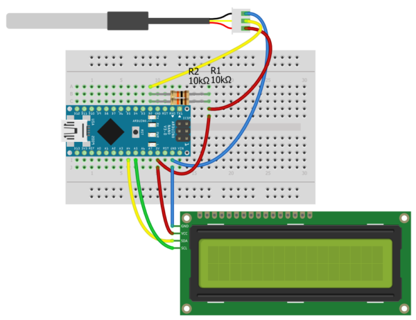
Для начала просто выведем температуру с датчика на дисплей.
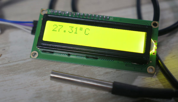
Программа 2
Теперь будем выводить такую строку: “температура с момента запуска программы” -> “текущая температура”. Может быть полезным для исследования изменения температуры. Нам нужно завести переменную для хранения первого значения, назовём её prevT . При запуске программы запросим температуру с датчика, подождём, запишем результат в переменную и будем выводить на дисплей как в предыдущем примере:
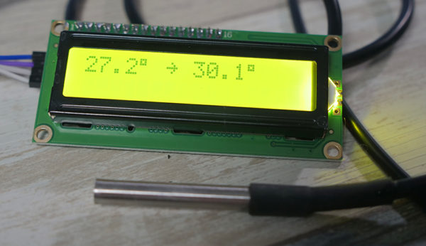
Также можно вывести время, прошедшее с момента запуска программы, например в формате часы:секунды.
- У нас есть функция millis() , которая возвращает время работы программы в миллисекундах.
- millis() / 1000 даст нам секунды, запишем в переменную sec .
- Чтобы получить количество секунд в пределах одной минуты, разделим секунды на 60: sec / 60
- Чтобы получить количество минут из общего количества секунд – нужно выполнить операцию остаток от деления, опять же на 60: sec % 60
- Чтобы выводить значения с ведущим нулём (например 03 вместо 3), сделаем простое условие: if (минуты < 10) lcd.print(0);
- Обернём вывод времени в функцию для лучшей читаемости кода
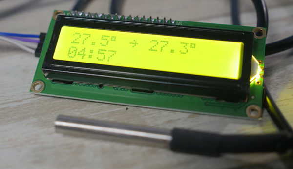
Программа 3
Следующая задача – опросить два термометра и вывести их текущие показания и разность.
- Для начала прошьём пример address_read из библиотеки microDS18B20
- Поочерёдно подключим два датчика, увидим их адреса и скопируем в блокнот
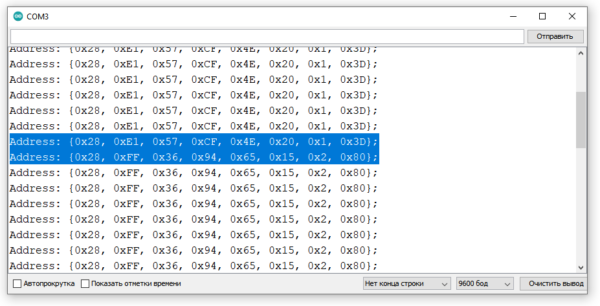
Далее аналогично примеру one_pin_many_sensors записываем полученные адреса в массивы и создаём два датчика. Дальнейшая работа ведётся с двумя датчиками:
Адаптер VGA>LVDS MT561-B. Как сделать LCD монитор своими руками.
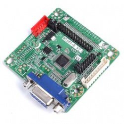
Адаптеры интерфейса LVDS в наше время не редкость. Они позволяют превратить отдельно лежащую матрицу в работоспособный дисплей или вернуть к жизни монитор с отказавшим скалером. Матрицы бывают очень разные, поэтому адаптеры обычно надо прошивать под конкретную матрицу. Это затрудняет их использование, потому что подбор прошивки неочевиден, а сама процедура не всегда обходится без программатора.
В сегодняшнем обзоре — адаптер, который обходится без таких сложностей. Его настройка сводится к установке нескольких перемычек на плате.
Пример использования и некоторые трудности, с которыми при этом можно столкнуться — под катом.
Итак, Вы обнаружили одинокую LCD матрицу. 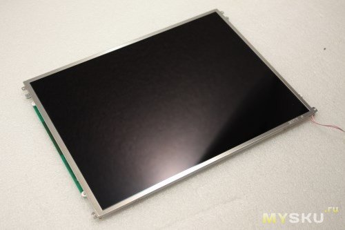
С чего бы начать процесс изготовления дисплея на её основе?
Естественно, с поиска документации. 
Переворачиваем матрицу экраном вниз, вбиваем найденное на этикетке наименование в Гугл и внимательно читаем даташит.
В первую очередь нас интересует пункт «Features» раздела «General descriptions». 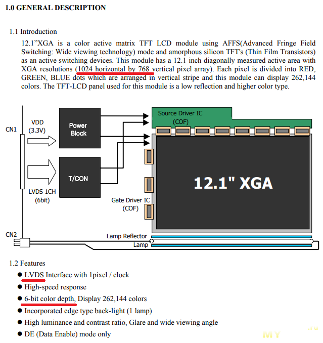
Помимо всего прочего там будет описан используемый LCD матрицей тип интерфейса. Здесь возможны варианты.
1. TTL интерфейс. Матрица когда-то стояла в очень древнем мониторе или ноутбуке. Единого стандарта не существует — плата управления проектировалась под конкретную матрицу. Использовать по назначению не получится, единственное, что можно в этом случае сделать — продать на барахолке. Возможно, кому-то этот артефакт и пригодится.
2. TMDS интерфейс. Матрицы с таким интерфейсом, насколько мне известно, использовались в Apple iMac G4, iMac G5 и ранних iMac Pro. Адаптер интерфейса не нужен — к DVI или HDMI такая матрица может подключаться напрямую.
3. eDP интерфейс. Матрицы от новых ноутбуков, Macbook Pro и iPad. К DisplayPort можно подключить через пассивный переходник, ко всему остальному — через активный конвертер стоимостью порядка $100.
4. LVDS интерфейс. Подавляющее большинство бывших в употреблении матриц от ноутбуков и мониторов. Подключаются без особых сложностей, адаптеры LVDS есть на любой вкус и кошелёк. Самые простые и дешёвые обрабатывают только VGA сигнал, те, что подороже, могут и DVI/HDMI переварить, и фильм с флэшки воспроизвести. Основной проблемой будет кабель между адаптером и матрицей. В общем, наш случай.
Видеоинтерфейс VGA был выпущен IBM в 1987 году и продержался в производстве более четверти века — выходить из употребления он начал только в 2015 году(но использующего его оборудования пока ещё очень много). Он использует аналоговый сигнал для передачи цветовой информации. Фактически такой интерфейс представляет собой всего 6 проводов — три сигнала цветности, два сигнала синхронизации и общий провод. 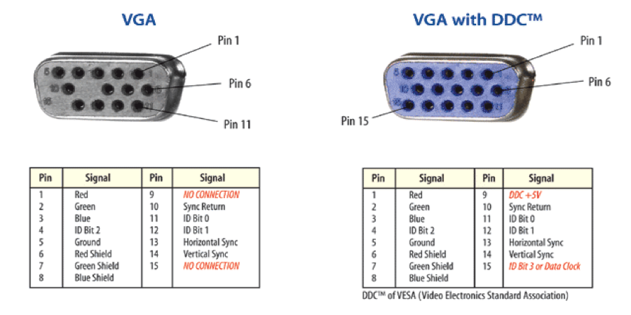
Оставшиеся контакты разъёма используются для работы интерфейса I2C, обеспечивающего передачу данных о дисплее. В первых версиях VGA они отсутствовали, так что если вдруг придётся паять такой кабель самому из старого — убедитесь, что в разъёме полный набор контактов, а в кабеле хватает жил, иначе Plug&Play работать не будет.
Так как основной поток данных передаётся в аналоговом виде, а LCD матрица требует цифровой сигнал, то без активного преобразователя не обойтись. Самые дешёвые преобразователи выполнены на микросхеме HX6856 от Himax, и если Вам достаточно одного VGA входа, то такой адаптер можно смело заказывать.
Адаптер имеет размеры 55х55 мм без учёта выступающих частей.
На верхней стороне печатной платы распаяны микросхема-преобразователь, 15-контактный разъём входа видеосигнала, три контактных гребёнки и группа перемычек. 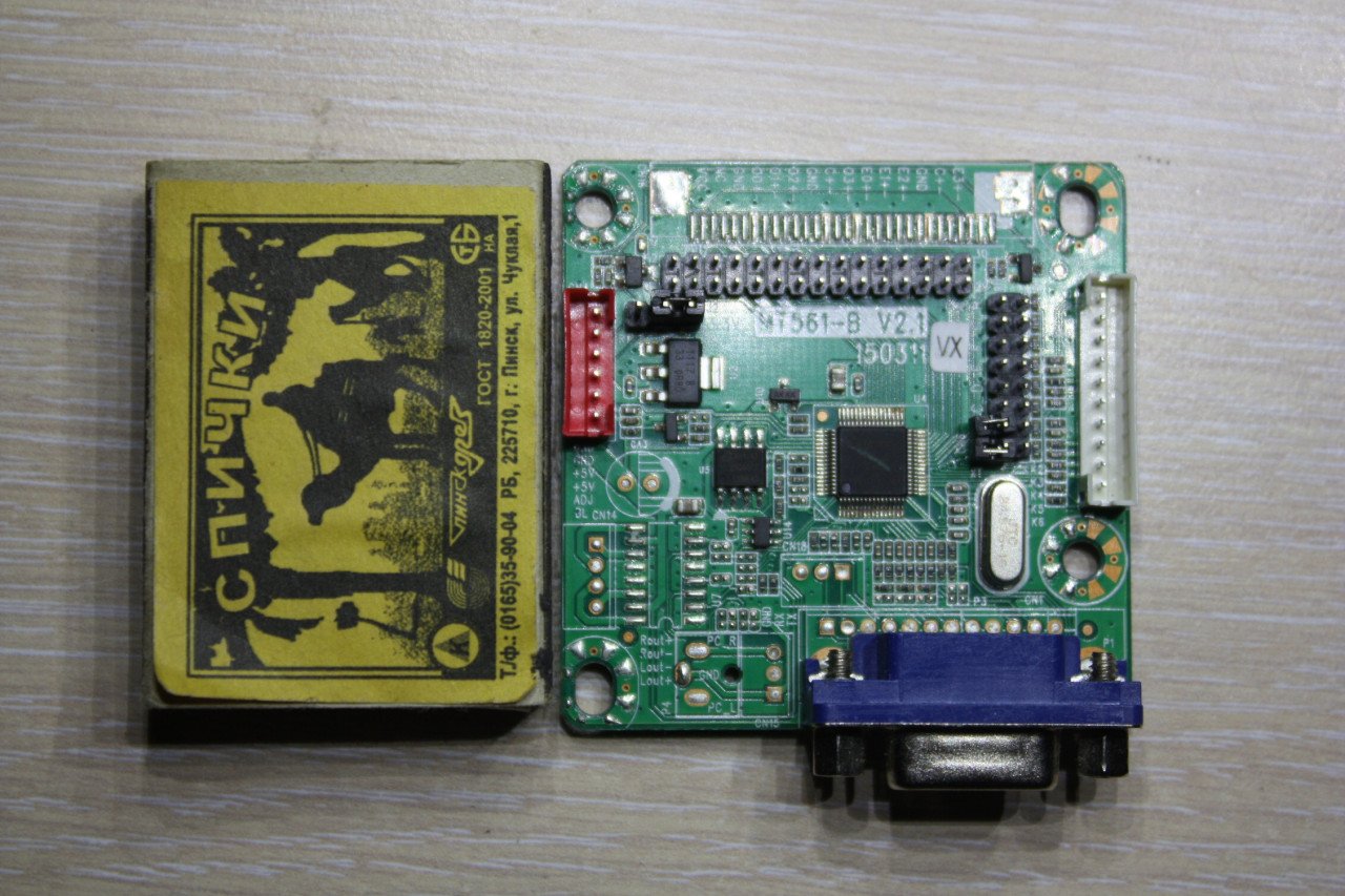
Ещё тут есть площадки для монтажа разъёма под плоский шлейф и пустующие места компонентов звукоусилителя. Все гребёнки имеют шаг выводов 2 мм.
На нижней стороне платы есть таблица с описанием расстановки перемычек под конкретные матрицы. Адаптер поддерживает матрицы с разрешением от 640*480 до 1920*1200 пикселей. 
При расстановке перемычек учитывайте, что обычно матрицы от настольных мониторов используют 8-битное кодирование цвета и питание 5В, а матрицы от ноутбуков — 6-битное и 3,3В. Будьте внимательны — 5В питания матрица от ноутбука не переживёт.
В интернете про эту плату гуляет вот такая картинка: 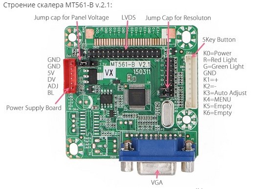
Руководствоваться ею не стоит, потому что на ней перевраны названия контактов в разъёмах.
Чтобы получить работающий монитор, достаточно подключить к плате адаптера матрицу, кнопочную панель, источник питания на 5В и обеспечить включение подсветки… и как раз с подсветкой возможны нюансы.
На старых матрицах подсветка осуществляется газоразрядной лампой, которая питается высоким напряжением от отдельного инвертора, который размещается рядом с матрицей и подключается к ней через двухконтактный разъём. И лампа, и инвертор могут выходить из строя как вместе, так и по отдельности, а без работающей подсветки изображение на матрице Вы скорее всего не увидите.
На матрицах поновее подсветка осуществляется светодиодной лентой, электроника управления которой почти всегда находится в самой матрице. Отказывает такая подсветка редко, питание у неё отдельное от самой матрицы, хотя и подаётся через тот же разъём.
В любом случае подачи только питания для запуска подсветки недостаточно, нужны ещё и управляющие сигналы.
Ответной части для гребёнки с шагом штырей 2 мм у меня нет, подопытная матрица старая, готовый кабель для её подключения к плате адаптера найти сложно, поэтому его придётся паять. Исходным материалом будет шлейф матрицы от ноутбука. Обрезаем от него разъём, подключавшийся к материнской плате, провода зачищаем и облуживаем, затем читаем описание матрицы дальше. В разделе «Interface connection» будет примерно вот такая таблица. 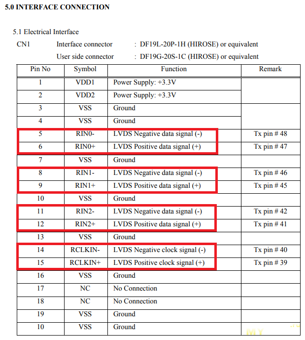
Из неё видно, что в нашем случае для передачи изображения достаточно соединить провода питания, земли и 4 дифференциальных сигнальных пары — 3 для передачи данных, 1 для тактирования.
Для других матриц количество задействуемых линий может быть больше: 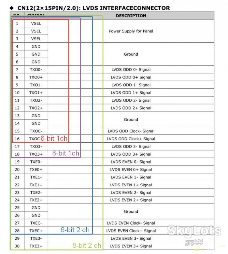
Берём тестер и ищем совпадающие контакты на плате.
Нумерация контактов на гребёнке и площадок для пайки разъёма под плоский шлейф идёт в противоположных направлениях.
Если кто будет паять: 
Паяем(желательно под лупой), промываем. 
Собираем адаптер, матрицу и инвертор подсветки вместе, подключаем питание… и не видим ничего. Судя по потребляемому току, инвертор сразу уходит в защиту. Замена на другой результата не принесла — скорее всего, виновата лампа подсветки матрицы.
Найти лампу на замену практически нереально — размер 12,1″ 4:3 неходовой, доноров нет, смысла везти под заказ тоже.
Зато есть битые матрицы 11,6″ 16:9. По длине они практически совпадают.
Разбираем обе матрицы(рекомендую перед этим протереть стол влажной тряпкой и вымыть волосы, чтобы с них не летела пыль).
Да, светодиодная лента от широкоформатной матрицы 11,6″ практически совпадает по длине с лампой от квадратной 12,1″. 
Ищем техническое описание на 11,6″ матрицу. 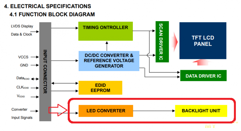
Подсветка питается напряжением 12В(допускается от 5 до 25В), управляется сигналами LED_EN(общее включение-выключение) и LED_PWM(управление яркостью) с уровнями 3,3В(предельно допустимо 5,5В, но лучше не надо). 
Ищем на плате точки LED_VCCS — на неё подаём +12В от блока питания, сигналы LED_EN и LED_PWM для общей проверки работоспособности имитируем батарейкой CR2032. Убеждаемся, что подсветка работает. 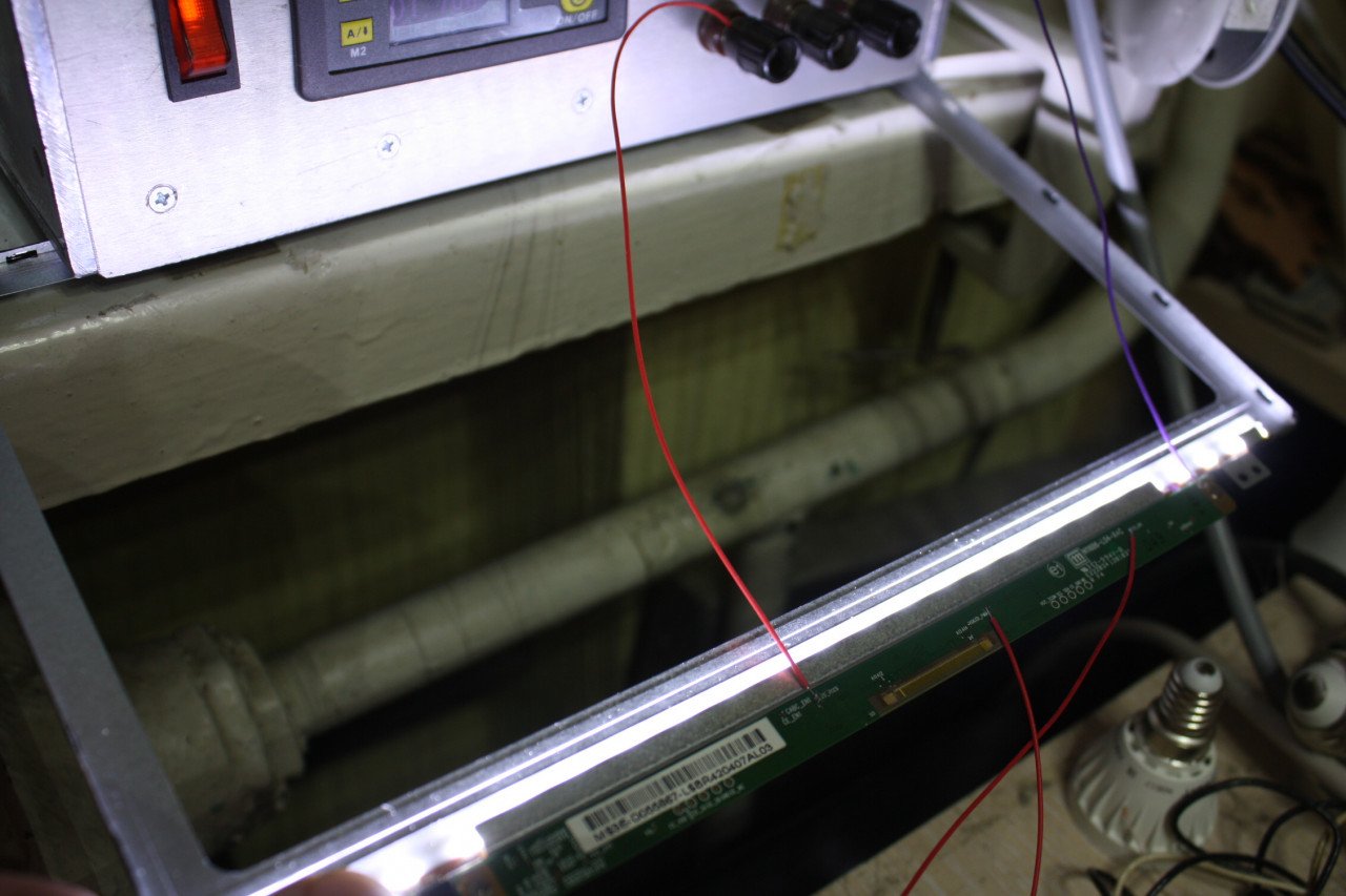
Берём напильник и пропиливаем в лотке от газоразрядной лампы щель для пропуска выводов светодиодной ленты. 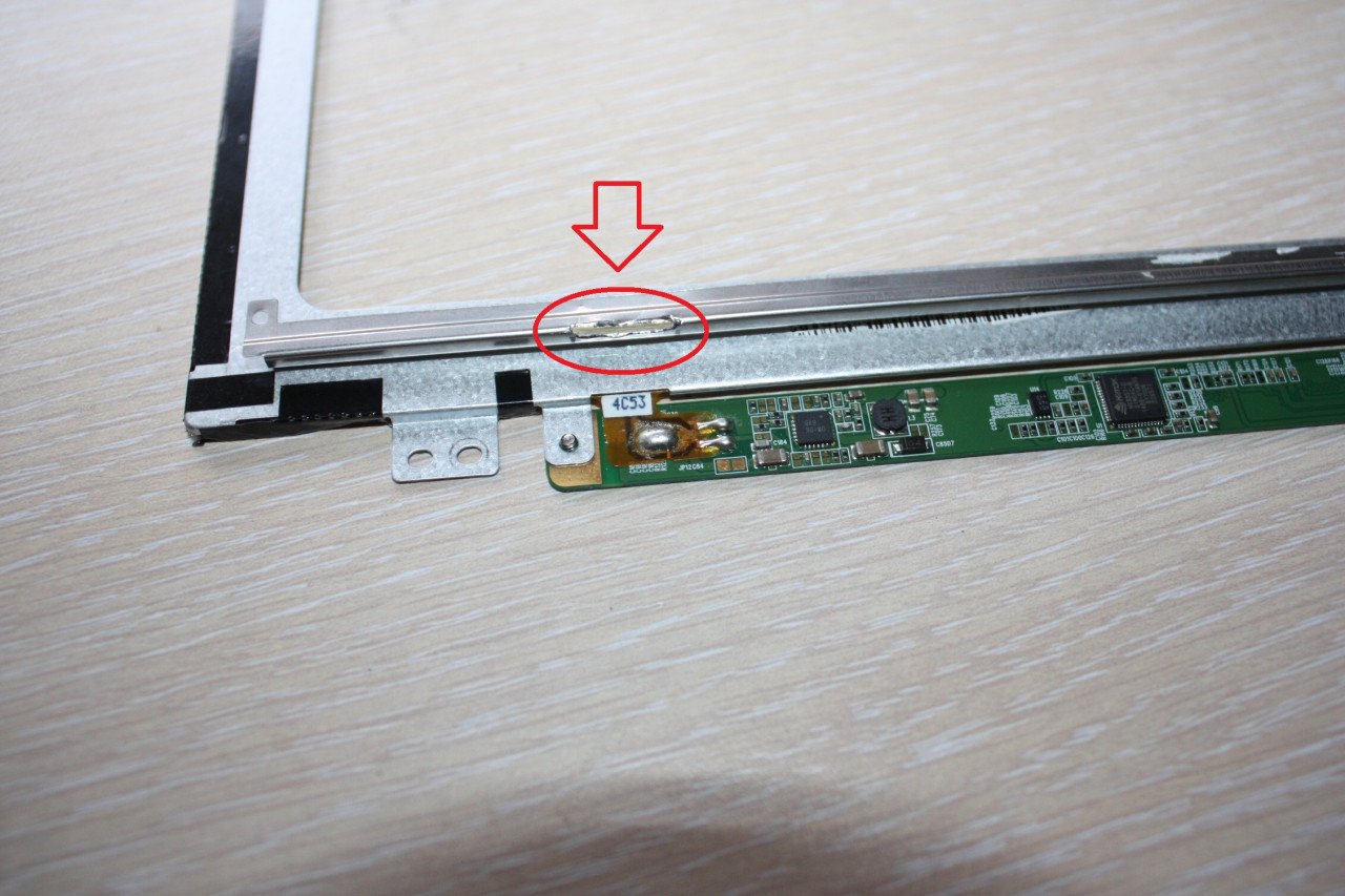
Переклеиваем на него светодиодную ленту вместе с родным белым скотчем. 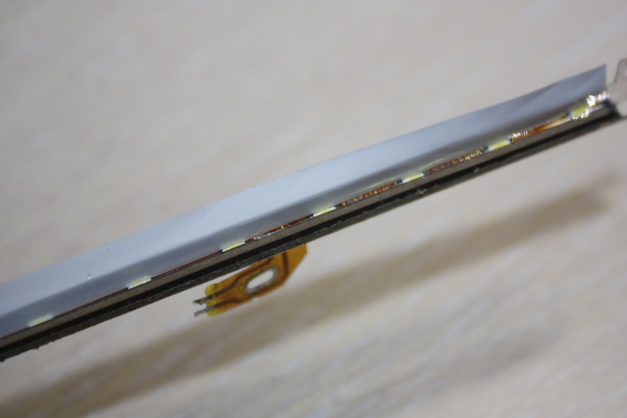
Собираем матрицу и проверяем работоспособность подсветки в сборе. 
Всё работает, можно идти дальше.
Фирменная кнопочная панель в комплекте адаптера отсутствует, но в Интернете есть её фотографии с обоих сторон, по которым можно восстановить принципиальную схему. 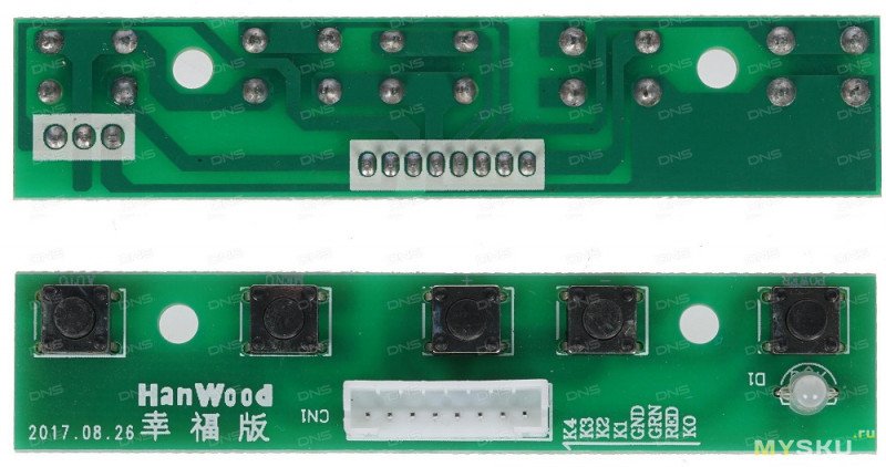
Ничего сложного — просто пять кнопок, замыкающихся на общий провод, и двухцветный светодиод.
Донорская плата с кнопками оказалась переусложнённой, поэтому я решил пересадить их на текстолит. 
Главной проблемой оказался поиск текстолита толщиной 1 мм, пришлось клеить из 2 по 0,5. 
Предварительная сборка перед включением. 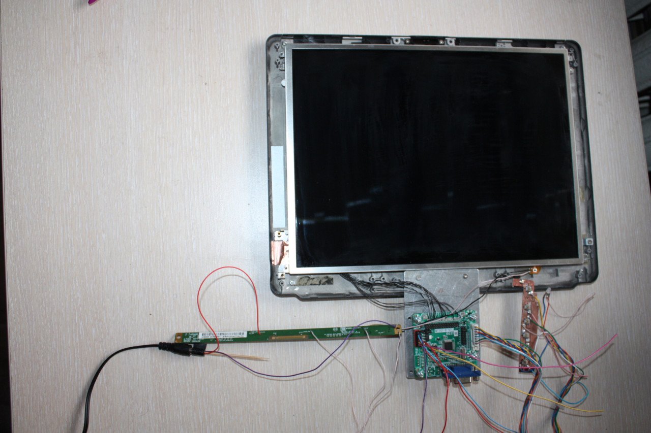
Подаём питание. О, оно живое! 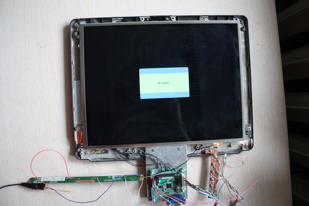
В отсутствие входного сигнала адаптер потребляет ток примерно 210 мА. 
Если через некоторое время сигнал не появится — он засыпает и снижает потребляемый ток до 12-15 мА. 
Подаём сигнал на вход VGA. Потребляемый ток подскакивает до примерно 350 мА. 
Ой, а что это у нас тут с цветами творится? 
А это мы неправильно перемычку выставили, и адаптер пытается затолкать 8-битный сигнал в 6-битный интерфейс.
Если на 6-битную матрицу подать 8-битный сигнал, то матрица покажет зверский калейдоскоп цветов, но правильного изображения не будет. Внешне картинка смахивает на цвета с сильно заниженной битностью (например если в Windows поставить глубину цвета не 32, а например 4 бита). Объясняется это тем, что согласно приведенной выше картинке часть полной картины не доходит до матрицы (ведь пара RX3 не подключена) — соответственно потеряна часть видеоинформации.
Если на 8-битную матрицу подать 6-битный сигнал, картинка будет правильной, но слишком темной и никакие регулировки не смогут вытянуть яркость и контрастность до нужного уровня
Выключаем, переставляем перемычку, включаем снова. 
Так оно намного лучше выглядит.
Тут можно ещё меню пощелкать кнопками, но смотреть тут по большому счёту не на что.
Начинаем приводить устройство в приличный вид.
Сначала возьмём и отрежем от платы управления подсветкой лишний текстолит, а то она на место старого инвертора не лезет. 
На красном 6-контактном разъёме платы адаптера есть пара штырей, обозначенных BL и ADJ. с точки зрения логики на контакте BL должен поддерживаться высокий логический уровень во время работы адаптера, а на ADJ зависящие от установленного в меню уровня яркости сигнал PWM или постоянное напряжение. В реальности же на ADJ всегда при поданном на адаптер питании присутствует 3,3В, на BL на время работы появляется 5В, а яркость регулируется средствами матрицы, поэтому контакты LED_EN и LED_PWM на плате управления подсветкой можно соединить вместе. Нагрузочной способности вывода BL адаптера при этом не хватает, поэтому для выработки сигнала управления подсветкой пришлось использовать эмиттерный повторитель с делителем напряжения в качестве нагрузки.
После этого плату подсветки можно изолировать, а провода в жгуте к кнопочной панели заменить на МГТФ 0,12. 
На данном этапе изделие выглядит следующим образом: 
Вывод: адаптер вполне работоспособен и легко настраивается. Если не смущает отсутствие цифровых входов и несколько странная логика управления подсветкой — вполне можно покупать. В качестве тестера ЖК матриц за свою цену адаптер почти идеален.