Характеристики
- ТипКонтроллер для размещения в невзрывоопасной зоне
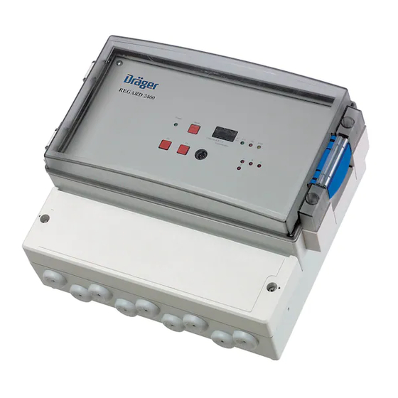
- Способ монтажаНастенный
- ГазыТоксичные и горючие газы (программируются пользователем или перед отгрузкой)
- Измерительные диапазоныИзмерительные диапазоны и единицы измерения зависят от типа датчика газов
- Способ настройки (программирования)С помощью набора для программирования
- Количество входных каналов1 — 4
- Входы2-/3-проводные датчики газов с выходом 4–20 мА или сенсорные датчики Dräger Polytron SE Ex
- ВыходыБеспотенциальные контакты реле (общие на 4-е канала): 2 реле тревоги плюс 1 реле звукового сигнала и 1 реле неиспр.
- Коммутационная способность каждого реле 250 В пер. тока, 2 А (DPCO)
- Интерфейс Modbus (для подключению к панели визуализации RVP 2400)
- Дополнительные модулиМаксимум до 4-х модулей: 1 модуль ввода-вывода + от 1 до 3 релейных модуля; или от 1 до 4 релейных модуля.
- Коммуникационная шина для дополнительных модулейRS485
- Модуль ввода-вывода6 цифровых входов (вход); 6 аналоговых выходов (выход)6 цифровых входов (вход); 6 аналоговых выходов (выход)
- Релейный модуль12 свободно конфигурируемых реле
- Контакты релеБеспотенциальные переключаемые (нормально запитанные) 250 В пер. тока, 2 A
- ДисплейМатричный дисплей
- Светодиоды (общие всех каналов)Активность, Неисправность, Тревога 1 и Тревога 2, Индикация электропитания
- Интерфейс пользователя3-х кнопочное управление; RS 232 для конфигурационного ПО
- Электропитание (имеется встроенный блок питания 2,5 А)Внешнее 24 В пост. тока или 110–230 В пер. тока
- Размеры (Ш x В x Г)185 x 213 x 118 мм
- Вес (приблизительно)1,5 кг
- Условия окружающей среды
- Температура–20 °C … 60 ºC
- Давление700–1300 гПа
- Влажность10–90 %, без конденсации
- Материал корпусаABS
- Класс защиты корпусаIP54
- Электромагнитная совместимость89/336/EWG и 92/31/EWG
- Спецификацию заказа см. в кратком описании или руководстве по эксплуатации.
-
Contents
-
Table of Contents
-
Bookmarks
Quick Links
de
4-Kanal Gaswarnzentrale
Gebrauchsanweisung, Seite 2 bis 27
en
Four Channel Control Unit
Instructions for Use, Page 28 to 53
®
2400 / 2410
D
Related Manuals for Dräger REGARD 2400
Summary of Contents for Dräger REGARD 2400
-
Page 1
® Dräger REGARD 2400 / 2410 4-Kanal Gaswarnzentrale Gebrauchsanweisung, Seite 2 bis 27 Four Channel Control Unit Instructions for Use, Page 28 to 53… -
Page 2: Table Of Contents
Product Description …………………… 30 Product Features ……………………30 Indicating and Control Elements ………………31 Electrical Connections and Installation …………….32 Dräger REGARD 2400 / 2410 and Catalytic Bead Sensors ……..37 Accessories ……………………..37 8.1. Installation of a Semi-Bridge Converters…………….37 8.2.
-
Page 3: For Your Safety
For Your Safety For Your Safety Strictly follow the Instructions for Use Any use of the control unit requires full understanding and strict observation of these Instruc- tions for Use. The control unit is only to be used for purposes specified here. Maintenance The control unit must be inspected and serviced regularly by trained service personnel.
-
Page 4: Intended Use
DANGER Dräger REGARD 2400 / 2410 must not be used and is not approved for use in areas where flammable and explosive gas mixtures may occur. Danger of explosion! Product Description Dräger REGARD 2400 / 2410 is a freely programmable controller unit for the connection of…
-
Page 5: Indicating And Control Elements
— One button for horn and alarm reset — Alarm memory is integrated — LEDs indicate the operating The Dräger REGARD 2400 / 2410 provides a scrolling display. The RS232 interface is for the configuration of the Dräger REGARD 2400 / 2410 via PC/Lap- top.
-
Page 6: Electrical Connections And Installation
Electrical Connections and Installation Electrical Connections and Installation DANGER Mains voltage (230 V, 50 Hz) Contact with this voltage can cause serious burns or even death. Work on electrical circuits shall only be carried out by a quallified electrician. Disconnect the mains voltage before installation! WARNING The VDE regulations, the local accident-prevention regulations and these instructions for…
-
Page 7
Electrical Connections and Installation The table shows the connection on the terminals of the Dräger REGARD 2410 / 2410. Terminal Description +24 V 24 VDC Input RS485 Interface Fault norm. closed Alarm 1 norm. closed Alarm 2 norm. closed Horn norm. -
Page 8
— All relays are freely configurable via software. Using the 24 VDC power supply input on Dräger REGARD 2400 To use the 24 VDC power supply input on the Dräger REGARD 2400 first a cable connection inside of the unit has to be changed. -
Page 9
Electrical Connections and Installation Connection diagram Dräger REGARD 2400 Mainboard INTERNAL POWER SUPPLY UNIT REGARD 2400 Mainboard 110/230 V AC 24 V DC Input Output 24 V DC Input +24 V Error Alarm 2 Alarm 1 Horn Channel Channel 19 20 21… -
Page 10
Electrical Connections and Installation The table shows the connection on the terminals of the Dräger REGARD 2400. Terminal Description with SE Ex 4…20 mA Converter Module Channel A +24 V brown signal yellow black Channel B +24 V brown signal… -
Page 11: Dräger Regard 2400 / 2410 And Catalytic Bead Sensors
Dräger REGARD 2400 / 2410 and Catalytic Bead Sensors* IMPORTANT NOTICE: If a Dräger REGARD 2400 or Dräger REGARD 2410 should be connected to a catalytic bead sensor a semi bridge converter has to be used! There are 2 different converters that could be used: SC00016 internal converter for Dräger REGARD 2400…
-
Page 12: Polytron Ec Transmitter To Dräger Regard 2410 Via A Safety Barrier
Accessories 8.2. Polytron EC* Transmitter to Dräger REGARD 2410 via a Safety Barrier Example for Connection: Ex Area Safe Area 230 VAC 24 VDC Polytron – Dräger REGARD 24xx 4…20 mA Input 4…20mA Safety Barrier e.g. Stahl 9160/13-11-11 When using Safety Barriers from other suppliers, it is recommended that you refer to the Installation and Operating manual of the specific Safety Barrier being used.
-
Page 13: Digital Inputs
8.4. RS485 Output Terminal Dräger REGARD 2400 / 2410 On the Dräger REGARD 2400 and Dräger REGARD 2410 there are 3 contacts for the com- munication with optional modules (for Dräger REGARD 2400 see connection diagram page 32, for Dräger REGARD 2410 see connection diagram page 34) like I/O module (see…
-
Page 14: I/O Module
+ D8 The I/O module (input-output module) has 6 digital inputs and 6 analog outputs. The module communicates with the Dräger REGARD 2400 / Dräger Regard 2410 via the RS485 connec- tion. To connect the module with the Dräger REGARD 24xx the terminals A / B / COM must be used.
-
Page 15: Relay Module
The module communicates with the Dräger REGARD 2400 / 2410 via the RS485 connection. To connect the module with the Dräger REGARD 2400 / 2410 the terminals A / B / COM must be used. The module needs a seperate 24 VDC supply.
-
Page 16
Relay Module Module address Switch on Relay module address This represents module one This represents module two This represents module three This represents module four IMPORTANT NOTICE: When an I/O module is installed the addressing of the relay modules must be 1 to 3 only. The configuration address in the configuration software and the relay modules must be the same. -
Page 17: The Dräger Regard 2400 / 2410 Menu
LOG: Showing the status of the datalogger. On the following 3 pages the menu-structure of the Dräger REGARD 2400 / 2410 is descri- bed. To get to the different menu point the buttons F1, F2 or F1+F2 (together) have to be used.
-
Page 18
The Dräger REGARD 2400 / 2410 Menu Menu Value F1+F2 Error INHI Inhibit Function Code Activated F1+F2 Inhibit Function Error F1+F2 MOFF Average Value Code F1+F2 Average Value OFF Error F1+F2 TOUT Sub Menu Code Relay Test F1+F2 Relay Test… -
Page 19
The Dräger REGARD 2400 / 2410 Menu Relay-Test-Menu F1+F2 current conditon de-energized energized T1 x Alarm relay 1 F1+F2 T2 x Alarm relay 2 F1+F2 THUx Horn relay F1+F2 TERx Error relay F1+F2… -
Page 20
The Dräger REGARD 2400 / 2410 Menu Configuration-Information-Menu A1Fu A2Fu R1 x A123 * Alarm function * Alarm function Function relay 1 Value threshold 1 threshold 2 F1 o. F2 A1Le A2Le R1xx A Un * value * value Time function… -
Page 21: Configuration
13. Maintenance 13.1. Inhibit The «Inhibit» function on the Dräger REGARD 2400 / 2410 locks all relays while calibrating or configuring the unit. The «Inhibit» mode will reset itself automatically after 20min. To activate «Inhibit» see Flow-Chart on page 44.
-
Page 22
The output current can be checked with a voltmeter at the two test points on the left hand side of the converter («Measuring Point 4…20mA»). Alternatively you may refer to the dis- play of the Dräger REGARD 2400, provided that the corresponding channel is configured correctly. -
Page 23: Potentiometers And Test Points At The Converter
Use the potentiometer «Adjust sensor sensitivity» to adjust the output current to the value which corresponds to the span gas being used. If a 50 %LEL reference gas is used, the display on the Dräger REGARD 2400 shall indicate «50»; the voltmeter should indicate 1.2 V (corresponding to 12 mA).
-
Page 24: Technical Data
Technical Data 14. Technical Data Dräger REGARD 2410 Supply Voltage d.c. 24 VDC ±10 % Power Consumption w/o connected Approx. 2.5 W sensors 4…20 mA Input Channels Digital Inputs Input 4…20 mA, input load 350 Ohm error at <3.5 mA error at >23 mA fault hysteresis 0.2 mA Output Relays…
-
Page 25
Technical Data Dräger REGARD 2400 Supply Voltage a.c. 110/230 VAC ±10 %, 50hz Supply Voltage d.c. 24 VDC ±10 % Power Consumption w/o connected Approx. 3 W sensors 4…20 mA Input Channels Digital Inputs Input 4…20 mA, input load 350 Ohm error at <3.5 mA… -
Page 26
Technical Data I/O Module Supply Voltage d.c. 24 VDC ±10 % Power Consumption Approx. 3 W Communication RS485 Input 6 digital inputs Output 6 analogue outputs Ambient Conditions Temperature: –20 C to 60 Relative Humidity: 10 % to 90 % r.h. Cable Terminals Screw terminals for solid wires up to 4 mm… -
Page 27: Order List
External Converter Module SE Ex 4-20 mA, 36 04 655 DIN Rail mounting, for Dräger REGARD 2410 I/O module for Dräger REGARD 2400 / 2410 SC 00 018 Relay module for Dräger REGARD 2400 / 2410 SC 00 019 Configuration Set International (Cable and Software)
-
Page 28: Zulassungen / Appovals
Zulassungen / Appovals Zulassungen / Appovals…
-
Page 29
Zulassungen / Appovals… -
Page 30
Zulassungen / Appovals… -
Page 31
Zulassungen / Appovals… -
Page 32: Konformitätserklärung / Decaration Of Conformity
Konformitätserklärung / Decaration of Conformity Konformitätserklärung / Decaration of Conformity…
-
Page 34
Dräger Safety AG & Co. KGaA Revalstraße 1 D-23560 Lübeck Germany Tel. +49 451 8 82- 0 +49 451 8 82- 20 80 www.draeger.com 90 33 025 — GA 4675.896 de_en © Dräger Safety AG & Co. KGaA 1st edition — 07_2007…
Конфигурационное программное обеспечение
12.4.2
Память данных
Рис. 19
В настройках регистратора данных можно выбрать данные, которые должен записывать
регистратор.
12.5
COM-порт
В пункте меню File – COM Port (Файл – COM-порт) можно выбрать соответствующие
настройки связи между ПК и контроллером, см. раздел «Меню проверки конфигурации —
Configuration Information» на стр. 148.
12.6
Передача конфигурации в REGARD 2400/2410
Для передачи конфигурации в REGARD 2400/2410 введите пароль «1875». Появится
всплывающее окно, сообщающее, что после загрузки новой конфигурации могут
измениться настройки реле и сработать сигнал тревоги. При загрузке новой конфигурации
память данных может быть сброшена.
12.7
Специальная функция
Специальная функция доступна при выборе Function – Special function (Функция –
Специальная функция). После ввода пароля «1875» можно будет изменить состояние
блокировки, среднего значения и проверки реле.
12.8
Онлайн мониторинг
Меню Function – Monitor (Функция – Монитор) позволяет просмотреть текущие
измеренные значения и тревоги REGARD 2400/2410. Зеленый индикатор указывает на
нормальное состояние,
предупреждение о неисправности.
156
красный индикатор указывает на активацию тревоги или
02233025_en.eps
Dräger REGARD 2400/2410
Table of Contents for Dräger REGARD 2400:
-
34 Electrical Connections and Installation Connection Diagram Dräger REGARD 2400 The picture shows a Dräger REGARD 2400. The mains supply voltage is 230 VAC or 24 VDC. The picture shows Dräger REGARD 2400 in an unpowered condition. — When switched on, Dräger REGARD 2400´s error- and alarm relays are normally energi- zed and contacts 8-9, 11-12, 14-15 are open. The horn relay remains unchanged when switched on (factory set configuration). — A
-
56 Zulassungen / Appovals
-
53 Order List 15. Order List Description Order No. Dräger REGARD 2410, 1 to 4-channel, 4…20 mA Controller for DIN Rail mounting SC 00 011 Dräger REGARD 2400, 1 to 4-channel, 4…20 mA Controller for wall mounting SC 00 014 Internal Converter Module SE Ex ➔ 4…20 mA for Dräger REGARD 2400 SC 00 016 External Converter Module SE Ex ➔ 4-20 mA, DIN Rail mounting, for Dräger REGARD 2410 36 04 655 I/O module for Dräger REGARD 2400 / 2410 SC 00 018 Relay module for Dräger REGARD 2400 / 2410 SC 00 019 Configuration Set International (Cable and Software) SC 00 04
-
41 Relay Module 10. Relay Module The Relay module has 12 free programmable relays. The Relay module makes it possible to create single alarms. The module communicates with the Dräger REGARD 2400 / 2410 via the RS485 connection. To connect the module with the Dräger REGARD 2400 / 2410 the terminals A / B / COM must be used. The module needs a seperate 24 VDC supply. The configuration of the module is done via Configuration Software. For configuration details please refer to the Software Configuration Instructions. Possibl
-
32 Electrical Connections and Installation 6. Electrical Connections and Installation The installation of the control unit shall be done in accordance with industrial standard fixed cable such as NYM-J, 3 x 1.5 mm 2 . The supply voltage for the control unit must be equipped with a separate fuse (maximum 1 A). Connection Diagram Dräger REGARD 2410 The picture shows a Dräger REGARD 2410. The supply voltage is 24 VDC. The picture shows the unit in an unpowere
-
28 Contents Contents 1. For Your Safety ……………………………………………………………………………………………………….. 29 1.1. Safety Symbols used in this Manual………………………………………………………………………….. 29 2. Intended Use ………………………………………………………………………………..
-
46 The Dräger REGARD 2400 / 2410 Menu Configuration-Information-Menu 01333025_01_en.eps F1 o. F2 F2 F1 o. F2 F1 o. F2 F1 o. F2 F1 o. F2 F1 o. F2 F1 o. F2 F1 F1 F1 F1 F1 F1 F1 F1 A123 Value * : depending on the variant and settings A Un Unit A No Number of measuring gas A Mi * Interval of average value A Ze Min range A Sp Max range R1 x Function relay 1 R2 x Function relay 2 F2 F2F2 F2F2 F2F2 F1 o. F2 F2 F2 F2 F2 F1 o. F2 A1Fu * Alarm function threshold 1 A1Le * value threshold 1
-
42 Relay Module Module address Switch on Relay module address 0 0 4 This represents module one 1 1 1 0 5 This represents module two 0 1 0 1 6 This represents module three 1 0 1 1 7 This represents module four 0 0 IMPORTANT NOTICE: When an I/O module is installed the addressing of the relay modules must be 1 to 3 only. The configuration address in the configuration software and the relay modules must be the same. 01033025_01.eps 0 1 0 1
-
44 The Dräger REGARD 2400 / 2410 Menu Menu 01133025_01_en.eps Value INHI Inhibit Function Inhibit Function Activated Code F1 F2 F1 F2 F1 F2 F1 F2 F1 F2 F1 F2 F1+F2 F1+F2 Error Error Error F1+F2 F1+F2 F1+F2 F1+F2 F1+F2 F1+F2 F1+F2 F1+F2 F1+F2 F1+F2 MOFF Average Value OFF Average Value OFF Code TOUT Relay Test Sub Menu Relay Test Code SOFT Software Version V2.1 Software Version MOD Modbus Slave Setting Sub Menu
-
29 For Your Safety 1. For Your Safety Strictly follow the Instructions for Use Any use of the control unit requires full understanding and strict observation of these Instruc- tions for Use. The control unit is only to be used for purposes specified here. Maintenance The control unit must be inspected and serviced regularly by trained service personnel. Repair of the control unit may only be carried out by trained service personnel. We recommend that a service contract be obtained
Questions, Opinions and Exploitation Impressions:
You can ask a question, express your opinion or share our experience of Dräger REGARD 2400 device using right now.