инструкцияYamaha RX-V457

AV Receiver
Ampli-tuner audio-vidéo
OWNER’S MANUAL
MODE D’EMPLOI
BEDIENUNGSANLEITUNG
BRUKSANVISNING
GEBRUIKSAANWIJZING
ИНСТРУКЦИЯ ПО ЭКСПЛУАТАЦИИ
G
Посмотреть инструкция для Yamaha RX-V457 бесплатно. Руководство относится к категории приемники, 2 человек(а) дали ему среднюю оценку 8.9. Руководство доступно на следующих языках: русский, английский. У вас есть вопрос о Yamaha RX-V457 или вам нужна помощь? Задайте свой вопрос здесь
- English
- Français
- Deutsch
- Svenska
- Nederlands
- Русский
- LIST OF REMOTE CONTROL CODES
Главная
| Yamaha | |
| RX-V457 | |
| приемник | |
| русский, английский | |
| Руководство пользователя (PDF) |
Не можете найти ответ на свой вопрос в руководстве? Вы можете найти ответ на свой вопрос ниже, в разделе часто задаваемых вопросов о Yamaha RX-V457.
Когда звук считается слишком громким?
Уровень звука выше 80 децибел может нанести вред слуху. Уровень звука выше 120 децибел может нанести прямое повреждение слуху. Вероятность повреждения слуха зависит от частоты и продолжительности прослушивания.
Могут ли устройства разных марок подключаться друг к другу при помощи Bluetooth?
Да, Bluetooth — универсальный метод, позволяющий различным устройствам, оснащенным Bluetooth, подключаться друг к другу.
Что такое Bluetooth?
Bluetooth — это способ обмена данными по беспроводной сети между электронными устройствами с помощью радиоволн. Расстояние между двумя устройствами обменивающимися данными в большинстве случаев составляет не более десяти метров.
Что такое HDMI?
HDMI расшифровывается как «интерфейс для мультимедиа высокой четкости». Кабель HDMI используется для передачи аудио- и видеосигналов между устройствами.
Как лучше всего выполнять чистку приемник?
Для удаления отпечатков пальцев лучше всего использовать слегка влажную салфетку для уборки или мягкую чистую ткань. Пыль в труднодоступных местах лучше всего удаляется потоком сжатого воздуха.
Что такое Dolby Atmos?
Dolby Atmos — это технология, которая обеспечивает отражение звука от потолка к месту нахождения слушателя. Это позволяет создать эффект 5.1 при помощи всего лишь одного динамика.
Инструкция Yamaha RX-V457 доступно в русский?
Да, руководствоYamaha RX-V457 доступно врусский .
Не нашли свой вопрос? Задайте свой вопрос здесь
-
Contents
-
Table of Contents
-
Troubleshooting
-
Bookmarks
Quick Links
U
RX-V457
AV Receiver
OWNER’S MANUAL
Related Manuals for Yamaha RX-V457
-

-

-
Home Theater System Yamaha RX-Z9 Product Catalog
Digital home theater component, digital sound projector, digital audio server, digital audio terminal, optional speaker system, plasma display monitor, digital cinema projector, digital home theatre receiver, dvd player, dvd changer, home theatre speaker (44 pages)
-

-

-
-

-


Summary of Contents for Yamaha RX-V457
-
Page 1
RX-V457 AV Receiver OWNER’S MANUAL… -
Page 2: Important Safety Instructions
IMPORTANT SAFETY INSTRUCTIONS IMPORTANT SAFETY INSTRUCTIONS CAUTION RISK OF ELECTRIC SHOCK DO NOT OPEN CAUTION: TO REDUCE THE RISK OF ELECTRIC SHOCK, DO NOT REMOVE COVER (OR BACK). NO USER-SERVICEABLE PARTS INSIDE. REFER SERVICING TO QUALIFIED SERVICE PERSONNEL. • Explanation of Graphical Symbols The lightning flash with arrowhead symbol, within an equilateral triangle, is intended to alert you to the presence of uninsulated “dangerous voltage”…
-
Page 3
This product, when installed as indicated in the instructions contained in this manual, meets FCC requirements. Modifications not expressly approved by Yamaha may void your authority, granted by the FCC, to use the product. 2 IMPORTANT: When connecting this product to accessories and/or another product use only high quality shielded cables. -
Page 4
Retain this Owner’s Manual in a safe place for future reference. Since hearing damage from loud sounds is often undetectable until it is too late, YAMAHA and the Electronic Industries Association’s Consumer Electronics Group recommend you to avoid prolonged exposure from excessive volume levels. -
Page 5: Table Of Contents
INTRODUCTION FEATURES… 2 GETTING STARTED… 3 Supplied accessories … 3 Installing batteries in the remote control … 3 CONTROLS AND FUNCTIONS … 4 Front panel … 4 Remote control… 6 Using the remote control … 7 Front panel display … 8 Rear panel …
-
Page 6: Features
Center: 85 W Surround: 85 W + 85 W Surround back: 85 W Sound field features Proprietary YAMAHA technology for the creation of sound fields Dolby Digital/Dolby Digital EX decoder DTS/DTS-ES Matrix 6.1, Discrete 6.1, DTS Neo:6, DTS 96/24 decoder…
-
Page 7: Getting Started
Supplied accessories Please check that you received all of the following parts. Remote control CODE SET TRANSMIT Batteries (4) SYSTEM POWER POWER STANDBY POWER (AAA, R03, UM-4) MD/CD-R TUNER SLEEP DTV/CBL V-AUX MULTI CH IN TV VOL TV CH VOLUME TV MUTE TV INPUT MUTE…
-
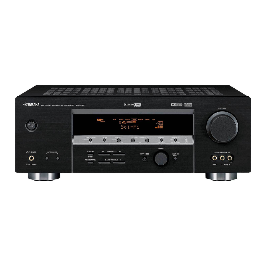
Page 8: Controls And Functions
CONTROLS AND FUNCTIONS CONTROLS AND FUNCTIONS Front panel STANDBY SEARCH MODE PHONES SPEAKERS SILENT CINEMA 1 STANDBY/ON Turns on this unit or sets it to the standby mode. When you turn on this unit, you will hear a click and there will be a 4 to 5-second delay before this unit can reproduce sound.
-
Page 9
CONTROLS AND FUNCTIONS 0 VIDEO AUX jacks Input audio and video signals from a portable external source such as a game console. To reproduce source signals from these jacks, select V-AUX as the input source. A VOLUME Controls the output level of all audio channels. This does not affect the REC OUT level. -
Page 10: Remote Control
CONTROLS AND FUNCTIONS Remote control This section describes the function of each control on the remote control used to control this unit. To operate other components, see “REMOTE CONTROL FEATURES” on page 63. CODE SET TRANSMIT POWER POWER STANDBY MD/CD-R TUNER DTV/CBL V-AUX…
-
Page 11: Using The Remote Control
B SYSTEM POWER Turns on the power of this unit. C SLEEP Sets the sleep timer. D MULTI CH IN Selects multi-channel input when using an external decoder (etc.). E AMP Selects the AMP mode. You must select the AMP mode to control the main unit.
-
Page 12: Front Panel Display
CONTROLS AND FUNCTIONS Front panel display VIRTUAL SILENT CINEMA MATRIX DISCRETE DIGITAL STANDARD ZONE2 ZONE2 NIGHT PL x 1 Decoder indicators When any of this unit’s decoders function, the respective indicator lights up. 2 VIRTUAL indicator Lights up when Virtual CINEMA DSP is active (see page 31).
-
Page 13
CONTROLS AND FUNCTIONS K 96/24 indicator Lights up when a DTS 96/24 signal is input to this unit. L LFE indicator Lights up when the input signal contains the LFE signal. M Input channel indicators/speaker indicators Indicate the channel components of the current digital input signal. -
Page 14: Rear Panel
CONTROLS AND FUNCTIONS Rear panel MULTI CH INPUT AUDIO VIDEO VIDEO FRONT DTV/ SURROUND DIGITAL CENTER INPUT WOOFER OPTICAL DTV/CBL (PLAY) CD-R VIDEO (REC) WOOFER MONITOR OUT COAXIAL AUDIO OUTPUT 1 DIGITAL INPUT jacks See pages 15, 17 and 18 for details. 2 MULTI CH INPUT jacks See page 16 for connection information.
-
Page 15: Speaker Setup
Place this speaker directly behind the listening position and at the same height as the surround speakers. Subwoofer The use of a subwoofer, such as the YAMAHA Active Servo Processing Subwoofer System, is effective not only for reinforcing bass frequencies from any or all channels,…
-
Page 16: Speaker Connections
SPEAKER SETUP Speaker connections Be sure to connect the left channel (L), right channel (R), “+” (red) and “–” (black) properly. If the connections are faulty, no sound will be heard from the speakers, and if the polarity of the speaker connections is incorrect, the sound will be unnatural and lack bass.
-
Page 17
Connect surround speakers (6, 7) to these terminals. SUBWOOFER jack Connect a subwoofer with built-in amplifier (1), such as the YAMAHA Active Servo Processing Subwoofer System, to this jack. SURROUND BACK terminals Connect a surround back speaker (5) to these terminals. -
Page 18: Connections
CONNECTIONS Before connecting components CAUTION Do not connect this unit or other components to the mains power until all connections between components are complete. Cable indications For analog signals left analog cables right analog cables For digital signals optical cables coaxial cables For video signals video cables…
-
Page 19: Connecting Video Components
CONNECTIONS Connecting video components Connections for DVD playback Note Be sure to connect your video source components in the same way you connect your video monitor to this unit. For example, if you connect your video monitor to this unit using a VIDEO connection, connect your video source components to this unit using the VIDEO connections.
-
Page 20: Connecting To Multi Ch Input Jacks
CONNECTIONS Connecting to the MULTI CH INPUT jacks This unit is equipped with 6 additional input jacks (left and right FRONT, CENTER, left and right SURROUND and SUBWOOFER) for discrete multi-channel input from a multi-format player, external decoder, sound processor or pre- amplifier.
-
Page 21
Connections for other video components Note • Be sure to connect your video source components in the same way you connect your video monitor to this unit. For example, if you connect your video monitor to this unit using a VIDEO connection, connect your video source components to this unit using the VIDEO connection. -
Page 22: Connecting Audio Components
CONNECTIONS VIDEO AUX VIDEO AUDIO Audio out R Audio out L Video out Connecting audio components Connections for audio components Audio out CD player Coaxial out Game console or video camera DIGITAL INPUT ( PLAY ) CD-R ( REC ) COAXIAL AUDIO (U.S.A.
-
Page 23: Connecting The Fm And Am Antennas
AM antenna is connected to this unit. • A properly installed outdoor antenna provides clearer reception than an indoor one. If you experience poor reception quality, an outdoor antenna may improve the quality. Consult the nearest authorized YAMAHA dealer or service center about outdoor antennas. CONNECTIONS…
-
Page 24: Connecting The Power Supply Cord
CONNECTIONS Connecting the power supply cord Connecting the AC power cord Plug the power cord into an AC wall outlet. AC OUTLET(S) (SWITCHED) U.K. and Australia models … 1 outlet Korea model …None Other models …2 outlets Use these outlets to connect the power cords from your other components to this unit.
-
Page 25: Speaker Impedance Setting
Speaker impedance setting CAUTION If you are using 4 or 6 ohm speakers, set the impedance to 4 or 6 ohms as follows before turning on the power. Be sure this unit is in the standby mode. Turn off the power to this unit, and while holding down STRAIGHT (EFFECT), press STANDBY/ON.
-
Page 26: Basic Setup
BASIC SETUP The basic setup feature is a useful way to set up your system quickly and with minimal effort. • If you wish to configure the unit manually using more precise adjustments, use the detailed parameters in SOUND MENU (page 56) instead of using BASIC SETUP.
-
Page 27
Press d to display the SPEAKERS parameter. PRESET/CH ENTER Press j / i to select the number of speakers you connected. SPEAKERS .. 6spk Choices Display Front L/R 2spk SL SB SR SL SB SR Front L/R, Center L L C R 3spk SL SB SR Front L/R, Surround L/R… -
Page 28
BASIC SETUP To balance the speaker levels Perform the following steps after step 13 (see page 23). V-AUX DTV/CBL The unit outputs the test tone from the selected speaker and the left front (or left surround) speaker in turn. The indicator of the speaker currently outputting the test tone flashes in the front panel display. -
Page 29: Playback
Basic operations STANDBY PRESET/TUNING FM/AM A/B/C/D/E l PRESET/TUNING/CH h MEMORY TUNING MODE SEARCH MODE CATEGORY DISPLAY EDIT NEXT LEVEL MAN’L/AUTO FM AUTO/MAN’L MONO INPUT STRAIGHT PROGRAM PHONES SPEAKERS INPUT MODE MULTI CH INPUT EFFECT TONE CONTROL BASS/TREBLE SILENT CINEMA CODE SET TRANSMIT SYSTEM POWER…
-
Page 30
PLAYBACK Select a sound field program if desired. Press PROGRAM l / h repeatedly (or press AMP to select the AMP mode, then press one of the sound field program buttons on the remote control) to select a sound field program. (See page 49 for details about sound field programs.) PROGRAM Front panel… -
Page 31: Selecting Sound Field Programs
Selecting MULTI CH INPUT Press MULTI CH INPUT (or MULTI CH IN on the remote control) so that “MULTI CH INPUT” appears in the front panel display. MULTI CH INPUT Front panel MULTI CH INPUT Note When “MULTI CH INPUT” is shown in the front panel display, no other source can be played.
-
Page 32: Remote Control Operation
PLAYBACK Remote control operation CODE SET TRANSMIT TV VOL TV CH SYSTEM POWER POWER STANDBY POWER TV MUTE TV INPUT MD/CD-R TUNER SLEEP STEREO MUSIC DTV/CBL V-AUX MULTI CH IN STANDARD SELECT SPEAKERS PRESET/CH TV VOL TV CH VOLUME LEVEL TITLE BAND TV MUTE…
-
Page 33
Notes • Some 6.1-channel compatible discs do not have a signal (flag) which this unit can automatically detect. When playing these kinds of discs with 6.1-channel, select a decoder manually (PLIIx Music, EX/ES or EX). • 6.1-channel playback is not possible even if EXTD SUR. is pressed in the following cases: –… -
Page 34: Night Listening Modes
PLAYBACK Listening to high fidelity stereo sound (Direct Stereo) Direct Stereo allows you to bypass this unit’s decoders and DSP processors to enjoy pure high fidelity sound from 2- channel PCM and analog sources. Press PROGRAM l / h repeatedly (or press AMP to select the AMP mode, then press DIRECT ST.
-
Page 35: Selecting Input Modes
Downmixing to 2 channels You can enjoy 2-channel stereo playback even from multi- channel sources. Press PROGRAM l / h repeatedly (or press AMP to select the AMP mode, then press STEREO on the remote control) to select 2ch Stereo. PROGRAM Front panel Remote control…
-
Page 36
PLAYBACK Notes • When playing a DTS-CD/LD, be sure to set INPUT MODE to DTS. • If the digital output data of the player has been processed in any way, you may not be able to perform DTS decoding even if you make a digital connection between this unit and the player depending on the player. -
Page 37: Fm/Am Tuning
Automatic and manual tuning There are 2 tuning methods; automatic and manual. Automatic tuning is effective when station signals are strong and there is no interference. Automatic tuning STANDBY PRESET/TUNING FM/AM A/B/C/D/E l PRESET/TUNING/CH h MEMORY TUNING MODE SEARCH MODE CATEGORY DISPLAY EDIT…
-
Page 38: Presetting Stations
FM/AM TUNING Manual tuning If the signal from the station you want to select is weak, tune into it manually. Manually tuning into an FM station will automatically switch the tuner to monaural reception to increase the signal quality. Select TUNER and the reception band following steps 1 and 2 as described in “Automatic tuning”.
-
Page 39
Press and hold MEMORY (MAN’L/AUTO FM) for more than 3 seconds. The preset number, the MEMORY and AUTO indicators flash. After about 5 seconds, automatic presetting starts from the frequency currently displayed and proceeds toward the higher frequencies. MEMORY MAN’L/AUTO FM V-AUX DTV/CBL MD/CD-R… -
Page 40: Selecting Preset Stations
FM/AM TUNING Press PRESET/TUNING/CH l / h to select a preset station number (1 to
 while the MEMORY indicator is flashing. Press h to select a higher preset station number. Press l to select a lower preset station number. l PRESET/TUNING/CH h LEVEL V-AUX…
 -
Page 41: Exchanging Preset Stations
Press PRESET/TUNING/CH l / h (or PRESET/CH u / d on the remote control) to select a preset station number (1 to 8). The preset group and number appear in the front panel display along with the station band, frequency and the TUNED indicator lights up.
-
Page 42
FM/AM TUNING Select preset station “A5” using A/B/C/D/E and PRESET/TUNING/CH l / h. “A5” and the MEMORY indicator flash in the front panel display. l PRESET/TUNING/CH h A/B/C/D/E CATEGORY NEXT V-AUX DTV/CBL Press PRESET/TUNING (EDIT) again. The stations stored at the two preset assignments are exchanged. -
Page 43: Xm Satellite Radio Tuning
XM SATELLITE RADIO TUNING What is XM Satellite Radio? XM Satellite Radio is the satellite radio service with millions of listeners across the U.S., broadcasting live daily. XM’s channel lineup includes more than 130 digital channels of choice from coast to coast: 68 commercial- free music channels, featuring hip hop to opera, classical to country, bluegrass to blues;…
-
Page 44: Activating Xm Satellite Radio
XM SATELLITE RADIO TUNING Remote control functions Note The following controls are only available when the unit is in the TUNER mode. To switch to the TUNER mode, press TUNER to select TUNER as the input source. TV VOL TV CH VOLUME TV MUTE TV INPUT…
-
Page 45: Basic Xm Satellite Radio Operations
Press PRESET/TUNING/CH l / h (or PRESET/CH u / d on the remote control) to select channel “0”. l PRESET/TUNING/CH h LEVEL A-E/CAT. Front panel Note You cannot select channel “0” if the “All Channel Search mode” (see page 42) is not selected. Check the XM Satellite Radio ID number displayed in the front panel display and write it down.
-
Page 46: Xm Satellite Radio Search Modes
XM SATELLITE RADIO TUNING Switching XM information You can display XM information (such as channel number/name, category, or artist name/song title) for the channel currently selected in the front panel display. Press DISPLAY on the unit (or remote control during the TUNER mode) repeatedly to toggle between the following XM information display modes.
-
Page 47
To change the channel category, press CATEGORY (or A-E/CAT. j / i on the remote control) repeatedly. A/B/C/D/E CATEGORY NEXT A-E/CAT. Front panel Remote control To search a channel within all channels, press PRESET/TUNING/CH l / h (or PRESET/CH u / d on the remote control) repeatedly. -
Page 48: Preset Search Mode
XM SATELLITE RADIO TUNING Preset Search mode Prior to selecting a preset channel in the Preset Search mode, you should preset XM Satellite Radio channels. For details, see “Setting XM Satellite Radio preset channels” on page 45. All preset channels (A1 to E8) recalls “001 Preview”…
-
Page 49: Setting Xm Satellite Radio Preset Channels
Press the numeric buttons to enter the desired channel number. For example, to enter the number 123, press the numeric buttons as shown below. STEREO MUSIC The display changes as follows. V-AUX DTV/CBL MD/CD-R <XM> —1 V-AUX DTV/CBL MD/CD-R <XM> -12 V-AUX DTV/CBL MD/CD-R…
-
Page 50
XM SATELLITE RADIO TUNING While the MEMORY indicator is flashing, press CATEGORY (or A-E/CAT. j / i on the remote control) to select a preset group (A to E). The group letter appears. A/B/C/D/E CATEGORY NEXT A-E/CAT. Front panel DTV/CBL MD/CD-R V-AUX C [040] Deep… -
Page 51
Status and error messages If an operation takes longer than usual or an error occurs, one of the following messages may appear in the front panel display. In this case, read the cause and follow the corresponding remedies. Message CHECK ANTENNA The XM Connect and Play digital antenna accessory is not connected, or does not work properly. -
Page 52: Recording
RECORDING Recording adjustments and other operations are performed from the recording components. Refer to the operating instructions for those components. STANDBY l PRESET/TUNING/CH h PRESET/TUNING FM/AM A/B/C/D/E MEMORY SEARCH MODE CATEGORY EDIT NEXT LEVEL MAN’L/AUTO FM INPUT PHONES SPEAKERS STRAIGHT PROGRAM INPUT MODE EFFECT…
-
Page 53: Sound Field Program Descriptions
The YAMAHA CINEMA DSP modes are compatible with all Dolby Digital, DTS, and Dolby Surround sources. Set the input mode to AUTO (see page 31) to enable this unit to automatically switch to the appropriate digital decoder according to the input signal.
-
Page 54
SOUND FIELD PROGRAM DESCRIPTIONS Remote control Program button MOVIE THEATER Spectacle MOVIE THEATER Sci-Fi MOVIE THEATER Adventure MOVIE THEATER General SUR. STANDARD SUR. ENHANCED Features CINEMA DSP processing. This program creates the extremely wide sound field of a 70-mm movie theater. It precisely reproduces the source sound in detail, making both the video and the sound field incredibly real. -
Page 55: For Music Sources
For music sources You can select from the following sound fields when playing music sources, like CD, FM/AM broadcasting, tapes, etc. Program selection methods vary depending on sound field program types. For details on how to select sound field programs, see “Selecting sound field programs” on pages 27 to 31. Remote control Program…
-
Page 56: Advanced Operation
ADVANCED OPERATIONS Using the sleep timer Use this feature to automatically set this unit in the standby mode after a certain amount of time. The sleep timer is useful when you are going to sleep while this unit is playing or recording a source. The sleep timer also automatically turns off any external components connected to AC OUTLET(S).
-
Page 57: Manually Adjusting Speaker Levels
Manually adjusting speaker levels You can adjust the output level of each speaker while listening to a music source. This is also possible when playing sources through the MULTI CH INPUT jacks. Please note that this operation will override the level adjustments made in “BASIC SETUP”…
-
Page 58: Set Menu
SET MENU You can use the following parameters in SET MENU to adjust a variety of system settings and customize the way this unit operates. Change the initial settings (indicated in bold under each parameter) to reflect the needs of your listening environment.
-
Page 59: Using Set Menu
Using SET MENU Use the remote control to access and adjust each parameter. TV VOL TV CH VOLUME TV MUTE TV INPUT MUTE STEREO MUSIC ENTERTAIN MOVIE STANDARD SELECT EXTD SUR. DIRECT ST. SPEAKERS NIGHT STRAIGHT ENT. EFFECT PRESET/CH SET MENU LEVEL TITLE FAVOR.
-
Page 60: Sound Menu
SET MENU 1 SOUND MENU Use to manually adjust any speaker setting or compensate for video signal processing delays when using LCD monitors or projectors. Most of the SOUND MENU parameters are set automatically when you perform “BASIC SETUP” (see page 22). Speaker settings A)SPEAKER SET Use to manually adjust any speaker setting.
-
Page 61
Speaker level B)SP LEVEL Use these settings to manually balance the level of each speaker selected in SPEAKER SET (page 56). Choices: –10.0 dB to +10.0 dB • FL adjusts the balance of the front left speaker. • FR adjusts the balance of the front right speaker. •… -
Page 62: Input Menu
SET MENU Audio settings G)AUDIO SET Use to customize this units overall audio settings. Muting type MUTE TYP. Use to adjust how much the mute function reduces the output volume. Choices: FULL, –20dB • Select FULL to completely halt all output of sound. •…
-
Page 63: Option Menu
Input mode B)INPUT MODE Use this feature to designate the input mode for sources connected to the DIGITAL INPUT jacks when you turn on this unit (see page 31 for details about the input mode). Choices: AUTO, LAST • Select AUTO to allow this unit to automatically detect the type of input signal and select the appropriate input mode.
-
Page 64
SET MENU Zone set D) MULTI ZONE Use to specify the location of speakers connected to the SPEAKERS B terminals. Speaker B setting SP B Use this feature to select the location of the front speakers connected to the SPEAKERS B terminals. Choices: FRONT, ZONE B •… -
Page 65: Advanced Setup Menu
ADVANCED SETUP MENU The ADVANCED SETUP menu is displayed in the front panel display. • During the advanced setup procedure, audio output is muted. • During the advanced setup procedure, only the STANDBY/ON, STRAIGHT (EFFECT) and PROGRAM l / h buttons on the front panel are available for operation.
-
Page 66
ADVANCED SETUP MENU ADVANCED SETUP menu items Change the initial settings (indicated in bold under each parameter) to reflect the needs of your listening environment. Speaker impedance SP IMP. Use to switch the speaker impedance for this unit. Choices: 8 Ω MIN, 4 Ω MIN •… -
Page 67: Remote Control Features
REMOTE CONTROL FEATURES In addition to controlling this unit, the remote control can also operate other A/V components made by YAMAHA and other manufacturers. To control other components, you must set up remote control with the appropriate remote control codes.
-
Page 68: Setting Remote Control Codes
Note You may not be able to operate your YAMAHA component even if a YAMAHA remote control code is initially set as listed above. In this case, try to set other YAMAHA remote control code(s). Press an input selector button or select the component you want to set up.
-
Page 69: Controlling Other Components
Controlling other components Once you set the appropriate remote control codes, you can use this remote to control your other components. Note that some buttons may not correctly operate the selected component. Use the input selector buttons to select the component you want to operate. The remote control automatically switches to the appropriate control mode for that component.
-
Page 70: Switching Library Codes
To operate this unit 9992 using an alternative code. When using multiple YAMAHA receivers/amplifiers, you may be able to operate the other components simultaneously with the default code setting. In this case, set one of the alternative codes to operate this unit separately.
-
Page 71: Editing Sound Field Parameters
The acoustics in your room could be changed to those of a concert hall, a dance floor, or virtually any size room at all. This ability to create sound fields at will is exactly what YAMAHA has done with the digital sound field processor. EDITING SOUND FIELD PARAMETERS…
-
Page 72
EDITING SOUND FIELD PARAMETERS Repeat steps 2 through 4 as necessary to change other program parameters. Note You cannot change parameter values when “MEMORY GUARD” is set to ON. If you want to change the parameter values, set “MEMORY GUARD” to OFF (see page 59). Memory back-up The memory back-up circuit prevents the stored data from being lost even if this unit is set in the standby… -
Page 73: Sound Field Parameter Descriptions
SOUND FIELD PARAMETER DESCRIPTIONS You can adjust the values of certain digital sound field parameters so the sound fields are recreated accurately in your listening room. Not all of the following parameters are found in every program. DSP LEVEL (DSP level) Function: Adjusts the level of all the DSP effect sounds within a narrow range.
-
Page 74
SOUND FIELD PARAMETER DESCRIPTIONS For 6ch Stereo: Function: These parameters adjust the volume level for each channel in 6-channel stereo mode. Control range: 0 to 100% CT LEVEL (Center level) SL LEVEL (Surround left level) SR LEVEL (Surround right level) SB LEVEL (Surround back level) For PRO LOGIC IIx Music and PRO LOGIC II Music: PANORAMA (Panorama) -
Page 75: Troubleshooting
Refer to the chart below when this unit does not function properly. If the problem you are experiencing is not listed below or if the instruction below does not help, set this unit to the standby mode, disconnect the power cord, and contact the nearest authorized YAMAHA dealer or service center. General…
-
Page 76
TROUBLESHOOTING Problem The sound suddenly The protection circuitry has been activated goes off. because of a short circuit, etc. The sleep timer has turned the unit off. The sound is muted. Only the speaker on Incorrect cable connections. one side can be heard. -
Page 77
Problem Dolby Digital or DTS The connected component is not set to sources cannot be output Dolby Digital or DTS digital played. (Dolby Digital signals. or DTS indicator in The input mode is set to ANALOG. the front panel display does not light up.) A “humming”… -
Page 78
TROUBLESHOOTING Tuner Problem FM stereo reception is The characteristics of FM stereo noisy. broadcasts may cause this problem when the transmitter is too far away or the antenna input is poor. There is distortion, and There is multipath interference. clear reception cannot be obtained even with a good FM antenna. -
Page 79: Resetting The Factory Presets
RESETTING THE FACTORY PRESETS If you want to reset all of your unit’s parameters for any reason, do the following. This procedure completely resets ALL parameters, including the SET MENU, level, assign and tuner presets. Be sure this unit is in standby mode. STANDBY PRESET/TUNING FM/AM…
-
Page 80: Glossary
GLOSSARY Audio formats Dolby Digital Dolby Digital is a digital surround sound system that gives you completely independent multi-channel audio. With 3 front channels (left, center, and right), and 2 surround stereo channels, Dolby Digital provides 5 full-range audio channels. With an additional channel especially for bass effects, called LFE (low frequency effect), the system has a total of 5.1-channels (LFE is counted as 0.1 channel).
-
Page 81: Sound Field Programs
SILENT CINEMA YAMAHA has developed a natural, realistic sound effect DSP algorithm for headphones. Parameters for headphones have been set for each sound field so that accurate representations of all the sound field programs can be enjoyed on headphones.
-
Page 82: Video Signal Information
GLOSSARY Video signal information Component video signal With the component video signal system, the video signal is separated into the Y signal for the luminance and the P and P signals for the chrominance. Color can be reproduced more faithfully with this system because each of these signals is independent.
-
Page 83: Specifications
AUDIO SECTION • Minimum RMS Output Power for Front, Center, Surround, Surround back 20 Hz to 20 kHz, 0.06% THD, 8 Ω … 85 W • Maximum Power (EIAJ) [Asia, Korea and General models] 1 kHz, 10% THD, 8 Ω … 125 W •…
-
Page 84: List Of Remote Control Codes
LIST OF REMOTE CONTROL CODES ELIN ELTA A TANDY 0941 EMERSON ABEX 1151 ADMIRA 1141 ADVENTURA 1131 AIKO 1121 AIWA 1481 AKAI 0331, 1101, 1111 ALBA 0431 ALLERON 1091 ENVISION AMBASSADOR 1081 ERRES AMSTRAD 0481, 1081 ETRON ANAM 0251, 1041, 1051, FERGUSON 1061, 1071 FINLUX…
-
Page 85
0971, 0991, 1031, SYSTEM 1091, 1111, 1771 WATSON 1001 REALISTIC XOGEGO 1611, 1621, 1661, REGENCY/EASTERN0686 1741, 1761 RUNCO YAMAHA 0361, 1031, 1111, SAMSUNG 1951, 1961, 1971, SCIENTIC ATLANTA 1981 YOKO 1001 SCIENTIFIC ATLANTA 175/475 ZENITH 0011, 0041, 0891, 0991, 1771… -
Page 86: Dvd Player
0202, 0432, 0602, 0632, 0692, 0912, 0922, 0932 WARDS PENTAX 0592, 0602 PERDIO 0992 PHILCO 0002, 0932 PHILIPS 0002, 0282, 0402, YAMAHA 0492, 0932 ZENITH PILOT 0912 PIONEER 0442, 0542 PROSCAN 1002, 1012, 1022, DVD PLAYER 1032, 1042, 1052, 1062…
-
Page 87
IMPORTANT SAFETY INSTRUCTIONS IMPORTANT SAFETY INSTRUCTIONS CAUTION RISK OF ELECTRIC SHOCK DO NOT OPEN CAUTION: TO REDUCE THE RISK OF ELECTRIC SHOCK, DO NOT REMOVE COVER (OR BACK). NO USER-SERVICEABLE PARTS INSIDE. REFER SERVICING TO QUALIFIED SERVICE PERSONNEL. • Explanation of Graphical Symbols The lightning flash with arrowhead symbol, within an equilateral triangle, is intended to alert you to the presence of uninsulated “dangerous voltage”… -
Page 88
YAMAHA ELECTRONICS (UK) LTD. YAMAHA HOUSE, 200 RICKMANSWORTH ROAD WATFORD, HERTS WD18 7GQ, ENGLAND YAMAHA SCANDINAVIA A.B. J A WETTERGRENS GATA 1, BOX 30053, 400 43 VÄSTRA FRÖLUNDA, SWEDEN YAMAHA MUSIC AUSTRALIA PTY, LTD. 17-33 MARKET ST., SOUTH MELBOURNE, 3205 VIC., AUSTRALIA…

- Manuals
- Brands
- Yamaha Manuals
- Receiver
- RX-V457
- Owner’s manual
-
Contents
-
Table of Contents
-
Troubleshooting
-
Bookmarks
Quick Links
G
RX-V457
AV Receiver
Ampli-tuner audio-vidéo
OWNER’S MANUAL
MODE D’EMPLOI
BEDIENUNGSANLEITUNG
BRUKSANVISNING
GEBRUIKSAANWIJZING
ИНСТРУКЦИЯ ПО ЭКСПЛУАТАЦИИ
Related Manuals for Yamaha RX-V457
-
-

-
Home Theater System Yamaha RX-Z9 Product Catalog
Digital home theater component, digital sound projector, digital audio server, digital audio terminal, optional speaker system, plasma display monitor, digital cinema projector, digital home theatre receiver, dvd player, dvd changer, home theatre speaker (44 pages)
-
-
-
-
-
Summary of Contents for Yamaha RX-V457
-
Page 1
RX-V457 AV Receiver Ampli-tuner audio-vidéo OWNER’S MANUAL MODE D’EMPLOI BEDIENUNGSANLEITUNG BRUKSANVISNING GEBRUIKSAANWIJZING ИНСТРУКЦИЯ ПО ЭКСПЛУАТАЦИИ… -
Page 2
YAMAHA will not be The wire which is coloured BLUE must be connected held responsible for any damage resulting from use to the terminal which is marked with the letter N or of this unit with a voltage other than specified. -
Page 3: Table Of Contents
CONTENTS INTRODUCTION SOUND FIELD PROGRAMS FEATURES…………. 2 SOUND FIELD PROGRAM GETTING STARTED……….3 DESCRIPTIONS……….43 Supplied accessories ……….3 For movie/video sources………. 43 Installing batteries in the remote control ….3 For music sources ………… 45 CONTROLS AND FUNCTIONS ……4 Front panel …………..
-
Page 4: Features
◆ A SET MENU that provides you with items for Sound field features optimizing this unit for your audio/video system ◆ Proprietary YAMAHA technology for the creation of ◆ 6 additional input jacks for discrete multi-channel input ◆ S-video signal input/output capability sound fields ◆…
-
Page 5: Getting Started
GETTING STARTED GETTING STARTED Supplied accessories Please check that you received all of the following parts. 75-ohm/300-ohm antenna Remote control Batteries (2) AM loop antenna adapter (U.K. model only) (AA, R06, UM-3) SYSTEM POWER POWER POWER STANDBY MD/CD-R TUNER SLEEP DTV/CBL V-AUX MULTI CH IN…
-
Page 6: Controls And Functions
CONTROLS AND FUNCTIONS CONTROLS AND FUNCTIONS Front panel VOLUME STANDBY l PRESET/TUNING h PRESET/TUNING FM/AM A/B/C/D/E MEMORY TUNING MODE EDIT NEXT LEVEL MAN’L/AUTO FM AUTO/MAN’L MONO INPUT STRAIGHT PROGRAM PHONES SPEAKERS VIDEO AUX INPUT MODE MULTI CH INPUT EFFECT TONE CONTROL BASS/TREBLE VIDEO AUDIO…
-
Page 7
CONTROLS AND FUNCTIONS ■ Radio Data System tuning buttons PHONES (SILENT CINEMA) jack Outputs audio signals for private listening with K FREQ/TEXT headphones. When you connect headphones, no signals Press this button when the unit is receiving a Radio Data are output to the OUTPUT jacks or to the speakers. -
Page 8: Remote Control
CONTROLS AND FUNCTIONS Remote control 1 Infrared window This section describes the function of each control on the remote control used to control this unit. To operate other Outputs infrared control signals. Aim this window at the components, see “REMOTE CONTROL FEATURES” on component you want to operate.
-
Page 9: Using The Remote Control
CONTROLS AND FUNCTIONS D VOLUME +/– Using the remote control Increases or decreases the volume level. E MUTE The remote control transmits a directional infrared beam. Be sure to aim the remote control directly at the remote Mutes the sound. Press again to restore the audio output to control sensor on the main unit during operation.
-
Page 10: Front Panel Display
CONTROLS AND FUNCTIONS Front panel display V-AUX DTV/CBL MD/CD-R TUNER VIRTUAL SILENT CINEMA YPAO AUTO TUNED STEREO MEMORY MUTE VOLUME MATRIX DISCRETE DIGITAL HiFi DSP RT CT RT CT EON RT CT EON STANDARD ZONE2 ZONE2 NIGHT HOLD HOLD HOLD SLEEP 96/24 L C R…
-
Page 11
CONTROLS AND FUNCTIONS J Radio Data System indicators The name(s) of the Radio Data System data offered by the currently received Radio Data System station light(s) up. EON lights up when an Radio Data System station that offers the EON data service is being received. PTY HOLD lights up while searching for stations in the PTY SEEK mode. -
Page 12: Rear Panel
CONTROLS AND FUNCTIONS Rear panel COMPONENT VIDEO MULTI CH INPUT AUDIO VIDEO S VIDEO VIDEO DTV/ FRONT XM/DT AC OUTLETS SWITCHED MONITOR DTV/ SURROUND DIGITAL TUNER INPUT CENTER WOOFER OPTICAL SPEAKERS FRONT SURROUND – – – – DTV/CBL (PLAY) CD-R S VIDEO VIDEO 75Ω…
-
Page 13: Speaker Setup
Place this speaker directly behind the listening position and at the same height as the surround speakers. Subwoofer The use of a subwoofer, such as the YAMAHA Active Servo Processing Subwoofer System, is effective not only for reinforcing bass frequencies from any or all channels, 30˚…
-
Page 14: Speaker Connections
SPEAKER SETUP Speaker connections Tighten the knob to secure the wire. Be sure to connect the left channel (L), right channel (R), “+” (red) and “–” (black) properly. If the connections are faulty, no sound will be heard from the speakers, and if the polarity of the speaker connections is incorrect, the sound will be unnatural and lack bass.
-
Page 15
■ SURROUND terminals Connect surround speakers (6, 7) to these terminals. ■ SUBWOOFER jack Connect a subwoofer with built-in amplifier (1), such as the YAMAHA Active Servo Processing Subwoofer System, to this jack. Speaker layout ■ SURROUND BACK terminals Connect a surround back speaker (5) to these terminals. -
Page 16: Connections
CONNECTIONS CONNECTIONS Dust protection cap Before connecting components Pull out the cap from the optical jack before you connect the fiber optic cable. Do not discard the cap. When you are not using the optical jack, be sure to put the cap back in CAUTION place.
-
Page 17: Connecting Video Components
CONNECTIONS Connecting video components ■ Connections for DVD playback Note Be sure to connect your video source components in the same way you connect your video monitor to this unit. For example, if you connect your video monitor to this unit using a VIDEO connection, connect your video source components to this unit using the VIDEO connections.
-
Page 18
CONNECTIONS ■ Connecting to the MULTI CH INPUT jacks This unit is equipped with 6 additional input jacks (left and right FRONT, CENTER, left and right SURROUND and SUBWOOFER) for discrete multi-channel input from a multi-format player, external decoder, sound processor or pre- amplifier. -
Page 19
CONNECTIONS ■ Connections for other video components Notes • Be sure to connect your video source components in the same way you connect your video monitor to this unit. For example, if you connect your video monitor to this unit using a VIDEO connection, connect your video source components to this unit using the VIDEO connection. -
Page 20: Connecting Audio Components
CONNECTIONS Connecting audio components ■ Connections for audio components Audio out CD player ( PLAY ) Coaxial out CD-R ( REC ) COAXIAL Audio out Audio in MD recorder or tape deck…
-
Page 21: Connecting The Fm And Am Antennas
• A properly installed outdoor antenna provides clearer reception than an indoor one. If you experience poor reception quality, an outdoor antenna may improve the quality. Consult the nearest authorized YAMAHA dealer or service center about outdoor antennas. ■ Connecting the 75-ohm/300-ohm antenna adapter (U.K.
-
Page 22: Connecting The Power Supply Cord
CONNECTIONS Connecting the power supply cord ■ Connecting the AC power cord Plug the power cord into an AC wall outlet. ■ AC OUTLET(S) (SWITCHED) U.K. model …………1 outlet Other models …………2 outlets Use these outlets to connect the power cords from your other components to this unit.
-
Page 23: Speaker Impedance Setting
CONNECTIONS Speaker impedance setting Turning on the power When all connections are complete, turn on the power of CAUTION this unit. If you are using 4 or 6 ohm speakers, set the impedance to 4 or 6 ohms as follows before turning on the power. VOLUME Be sure this unit is in the standby mode.
-
Page 24: Basic Setup
BASIC SETUP BASIC SETUP The basic setup feature is a useful way to set up your system quickly and with minimal effort. Press ENTER to enter BASIC SETUP. • If you wish to configure the unit manually using more precise adjustments, use the detailed parameters in SOUND MENU (page 50) instead of using BASIC SETUP.
-
Page 25
BASIC SETUP Press d to display the SPEAKERS Press ENTER to confirm your selection. parameter. ENTER A/B/C/D/E ENTER PRESET/CH A/B/C/D/E If you selected SET, you hear a test tone from each PRESET/CH speaker in turn. “CHECK:TestTone” appears in the front panel display for a few seconds, then “CHECK: Press j / i to select the number of speakers OK?”. -
Page 26
BASIC SETUP ■ To balance the speaker levels Memory back-up Perform the following steps after step 13 (see page 23). The memory back-up circuit prevents the stored data from being lost even if this unit is in the standby mode. V-AUX DTV/CBL MD/CD-R… -
Page 27: Playback
PLAYBACK PLAYBACK Basic operations Select the input source. Use INPUT (or press one of the input selector buttons on the remote control) to select the input you desire. VOLUME INPUT MD/CD-R TUNER SLEEP STANDBY DTV/CBL V-AUX l PRESET/TUNING h PRESET/TUNING FM/AM A/B/C/D/E MEMORY…
-
Page 28
PLAYBACK ■ To adjust the tone Select a sound field program if desired. You can adjust the tonal quality Press PROGRAM l / h repeatedly (or press AMP of your front left and right TONE CONTROL speakers or headphones (when to select the AMP mode, then press one of the sound connected). -
Page 29: Selecting Sound Field Programs
PLAYBACK ■ Selecting MULTI CH INPUT Selecting sound field programs Press MULTI CH INPUT (or MULTI CH IN on the remote control) so that “MULTI CH INPUT” appears in ■ Front panel operation the front panel display. MULTI CH INPUT MULTI CH IN VOLUME STANDBY…
-
Page 30: Remote Control Operation
PLAYBACK ■ Remote control operation ■ Enjoying multi-channel software If you connected a surround back speaker, use this feature to enjoy 6.1-channel playback for multi-channel sources MODE PTY SEEK START using the Dolby Pro Logic IIx, Dolby Digital EX or TV VOL TV CH VOLUME…
-
Page 31
PLAYBACK When you select the SUR. STANDARD program: Notes PRO LOGIC • Some 6.1-channel compatible discs do not have a signal (flag) Dolby Pro Logic processing for any sources. which this unit can automatically detect. When playing these kinds of discs with 6.1-channel, select a decoder manually PLII Movie (PLIIx Music, EX/ES or EX). -
Page 32
PLAYBACK ■ Listening to high fidelity stereo sound ■ Night listening modes (Direct Stereo) The night listening modes are designed to improve listenability at lower volumes or at night. Choose either Direct Stereo allows you to bypass this unit’s decoders and NIGHT:CINEMA or NIGHT:MUSIC depending on the DSP processors to enjoy pure high fidelity sound from 2- type of material you are playing. -
Page 33: Selecting Input Modes
PLAYBACK ■ Downmixing to 2 channels Selecting input modes You can enjoy 2-channel stereo playback even from multi- channel sources. This unit comes with a variety of input jacks. Do the Press PROGRAM l / h repeatedly (or press following to select the type of input signals you want to AMP to select the AMP mode, then press use.
-
Page 34
PLAYBACK Notes Press u / d to display the following • When playing a DTS-CD/LD, be sure to set INPUT MODE to information about the input signal. DTS. • If the digital output data of the player has been processed in any way, you may not be able to perform DTS decoding even if you make a digital connection between this unit and the player depending on the player. -
Page 35: Fm/Am Tuning
FM/AM TUNING FM/AM TUNING Automatic and manual tuning Press TUNING MODE (AUTO/MAN’L MONO) so that the AUTO indicator lights up in the There are 2 tuning methods; automatic and manual. front panel display. Automatic tuning is effective when station signals are strong and there is no interference.
-
Page 36: Presetting Stations
FM/AM TUNING ■ Manual tuning Presetting stations If the signal from the station you want to select is weak, tune into it manually. Manually tuning into an FM station ■ Automatically presetting FM stations will automatically switch the tuner to monaural reception You can use the automatic preset tuning feature to store to increase the signal quality.
-
Page 37
FM/AM TUNING ■ Manually presetting stations Press and hold MEMORY (MAN’L/AUTO FM) You can also store up to 40 stations (8 stations x 5 groups) manually. for more than 3 seconds. The preset number, the MEMORY and AUTO indicators flash. After about 5 seconds, automatic presetting starts from the frequency currently VOLUME displayed and proceeds toward the higher… -
Page 38: Selecting Preset Stations
FM/AM TUNING Selecting preset stations Press PRESET/TUNING l / h to select a preset station number (1 to
while the You can tune any desired station simply by selecting the MEMORY indicator is flashing. preset station number under which it was stored. Press h to select a higher preset station number. -
Page 39: Exchanging Preset Stations
FM/AM TUNING Exchanging preset stations Press PRESET/TUNING l / h (or PRESET/ CH u / d on the remote control) to select a You can exchange the assignment of two preset stations preset station number (1 to 8). with each other. The example below describes the The preset group and number appear in the front procedure for exchanging preset station “E1”…
-
Page 40: Receiving Radio Data System Stations
FM/AM TUNING Receiving Radio Data System Press PRESET/TUNING (EDIT) again. stations The stations stored at the two preset assignments are exchanged. Radio Data System is a data transmission system used by PRESET/TUNING FM stations in many countries. The Radio Data System function is carried out among the network stations.
-
Page 41: Changing The Radio Data System Mode
FM/AM TUNING Changing the Radio Data System Notes mode • Do not press FREQ/TEXT until a Radio Data System indicator lights up in the front panel display. You cannot change the mode Four modes are available for displaying Radio Data if you press the button prior to this.
-
Page 42: Pty Seek Function
FM/AM TUNING PTY SEEK function Press PTY SEEK START to begin searching all preset Radio Data System stations. If you select the desired program type, this unit The selected program type flashes and the PTY automatically searches all preset Radio Data System HOLD indicator lights up in the front panel display stations that are broadcasting a program of the required while searching for stations.
-
Page 43: Eon Function
FM/AM TUNING ■ To cancel this function EON function Press EON repeatedly until no program type name is shown in the front panel display. This function uses the EON data service on the Radio Data System station network. If you select the desired program type (NEWS, INFO, AFFAIRS or SPORT), this unit automatically searches for all preset Radio Data System stations that are scheduled to broadcast the…
-
Page 44: Recording
RECORDING RECORDING Recording adjustments and other operations are Notes performed from the recording components. Refer to the • When this unit is set in the standby mode, you cannot record operating instructions for those components. between other components connected to this unit. •…
-
Page 45: Sound Field Program Descriptions
The YAMAHA CINEMA DSP modes are compatible with all Dolby Digital, DTS, and Dolby Surround sources. Set the input mode to AUTO (see page 31) to enable this unit to automatically switch to the appropriate digital decoder according to the input signal.
-
Page 46
SOUND FIELD PROGRAM DESCRIPTIONS Remote control Program Features Sources button MOVIE THEATER CINEMA DSP processing. This program creates the extremely wide sound field of a 70-mm movie theater. It precisely reproduces the source sound in detail, Spectacle making both the video and the sound field incredibly real. This is ideal for any kind of video source encoded with Dolby Surround, Dolby Digital or DTS (especially large-scale movie productions). -
Page 47: For Music Sources
SOUND FIELD PROGRAM DESCRIPTIONS For music sources You can select from the following sound fields when playing music sources, like CD, FM/AM broadcasting, tapes, etc. Program selection methods vary depending on sound field program types. For details on how to select sound field programs, see “Selecting sound field programs”…
-
Page 48: Advanced Operation
ADVANCED OPERATIONS ADVANCED OPERATIONS ■ Canceling the sleep timer Using the sleep timer Press SLEEP repeatedly until “SLEEP OFF” appears in the front panel display. Use this feature to automatically set this unit in the After a few seconds, “SLEEP OFF” disappears, and the standby mode after a certain amount of time.
-
Page 49: Manually Adjusting Speaker Levels
ADVANCED OPERATIONS Manually adjusting speaker levels You can adjust the output level of each speaker while listening to a music source. This is also possible when playing sources through the MULTI CH INPUT jacks. Please note that this operation will override the level adjustments made in “BASIC SETUP”…
-
Page 50: Set Menu
SET MENU SET MENU You can use the following parameters in SET MENU to adjust a variety of system settings and customize the way this unit operates. Change the initial settings (indicated in bold under each parameter) to reflect the needs of your listening environment.
-
Page 51: Using Set Menu
SET MENU Using SET MENU Press ENTER to enter the displayed menu. Repeat steps 5 and 6 to navigate to and enter the items Use the remote control to access and adjust each you want to adjust. parameter. To return to the previous menu level, press RETURN. FREQ/TEXT Press u / d and ENTER to select the MODE…
-
Page 52: Sound Menu
SET MENU Surround back speaker SUR. B 1 SOUND MENU Choices: LRG, SML, NONE • Select LRG if you have a large surround back speaker. Use to manually adjust any speaker setting or compensate • Select SML if you have a small surround back speaker. for video signal processing delays when using LCD The low-frequency signals of the surround back monitors or projectors.
-
Page 53
SET MENU ■ Speaker level ■ Center graphic equalizer B)SP LEVEL D)CENTER GEQ Use these settings to manually balance the level of each Use this feature to adjust the built-in 5-band graphic speaker selected in SPEAKER SET (page 50). equalizer for the center channel so that the tonal quality of Choices: –10.0 dB to +10.0 dB the center speaker matches that of the front speakers. -
Page 54: Input Menu
SET MENU ■ Dynamic range F)D. RANGE 2 INPUT MENU Use to select the amount of dynamic range compression to be applied to your speakers or headphones. This setting is Use to reassign digital input/outputs and select the input effective only when the unit is decoding Dolby Digital and mode.
-
Page 55: Option Menu
SET MENU ■ Input mode B)INPUT MODE 3 OPTION MENU Use this feature to designate the input mode for sources connected to the DIGITAL INPUT jacks when you turn on Use to adjust the optional system parameters. this unit (see page 31 for details about the input mode). Choices: AUTO, LAST ■…
-
Page 56
SET MENU ■ Zone set D)MULTI ZONE Use to specify the location of speakers connected to the SPEAKERS B terminals. Speaker B setting SP B Use this feature to select the location of the front speakers connected to the SPEAKERS B terminals. Choices: FRONT, ZONE B •… -
Page 57: Advanced Setup Menu
ADVANCED SETUP MENU ADVANCED SETUP MENU The ADVANCED SETUP menu is displayed in the front panel display. Press PROGRAM l / h repeatedly to move through the menu and select the item you want to set up. • During the advanced setup procedure, audio output is muted. •…
-
Page 58: Advanced Setup Menu Items
ADVANCED SETUP MENU ■ ADVANCED SETUP menu items Change the initial settings (indicated in bold under each parameter) to reflect the needs of your listening environment. Speaker impedance SP IMP. Use to switch the speaker impedance for this unit. Choices: 8 ! MIN»#4 !#MIN •…
-
Page 59: Remote Control Features
REMOTE CONTROL FEATURES REMOTE CONTROL FEATURES In addition to controlling this unit, the remote control can also operate other A/V components made by YAMAHA and other manufacturers. To control other components, you must set up remote control with the appropriate remote control codes.
-
Page 60: Setting Remote Control Codes
VOLUME TV VOL TV CH You may not be able to operate your YAMAHA component even if a YAMAHA remote control code is initially set as listed above. TV MUTE TV INPUT MUTE In this case, try to set other YAMAHA remote control code(s).
-
Page 61: Controlling Other Components
REMOTE CONTROL FEATURES Controlling other components Once you set the appropriate remote control codes, you can use this remote to control your other components. TV MUTE TV INPUT Note that some buttons may not correctly operate the MUTE SYSTEM STEREO MUSIC ENTERTAIN MOVIE…
-
Page 62: Editing Sound Field Parameters
ENTER A/B/C/D/E all. This ability to create sound fields at will is exactly what YAMAHA has done with the digital sound field PRESET/CH processor. Press j / i to change the parameter value.
-
Page 63
EDITING SOUND FIELD PARAMETERS Repeat steps 2 through 4 as necessary to change other program parameters. Note You cannot change parameter values when “MEMORY GUARD” is set to ON. If you want to change the parameter values, set “MEMORY GUARD” to OFF (see page 53). Memory back-up The memory back-up circuit prevents the stored data from being lost even if this unit is set in the standby… -
Page 64: Sound Field Parameter Descriptions
SOUND FIELD PARAMETER DESCRIPTIONS SOUND FIELD PARAMETER DESCRIPTIONS You can adjust the values of certain digital sound field parameters so the sound fields are recreated accurately in your listening room. Not all of the following parameters are found in every program. ■…
-
Page 65
SOUND FIELD PARAMETER DESCRIPTIONS For 6ch Stereo: Function: These parameters adjust the volume level for each channel in 6-channel stereo mode. Control range: 0 to 100% ■ CT LEVEL (Center level) ■ SL LEVEL (Surround left level) ■ SR LEVEL (Surround right level) ■… -
Page 66: Troubleshooting
Refer to the chart below when this unit does not function properly. If the problem you are experiencing is not listed below or if the instruction below does not help, set this unit to the standby mode, disconnect the power cord, and contact the nearest authorized YAMAHA dealer or service center. ■ General…
-
Page 67
TROUBLESHOOTING Refer to Problem Cause Remedy page The sound suddenly The protection circuitry has been activated Check that the impedance selector setting is correct. goes off. because of a short circuit, etc. Check that the speaker wires are not touching each —… -
Page 68
TROUBLESHOOTING Refer to Problem Cause Remedy page Dolby Digital or DTS The connected component is not set to Make an appropriate setting following the operating — sources cannot be output Dolby Digital or DTS digital instructions for your component. played. (Dolby Digital signals. -
Page 69
TROUBLESHOOTING ■ Tuner Refer Problem Cause Remedy to page FM stereo reception is The characteristics of FM stereo Check the antenna connections. noisy. broadcasts may cause this problem Try using a high-quality directional FM when the transmitter is too far away or antenna. -
Page 70: Resetting The Factory Presets
RESETTING THE FACTORY PRESETS RESETTING THE FACTORY PRESETS If you want to reset all of your unit’s parameters for any Press STANDBY/ON to confirm your reason, do the following. This procedure completely resets selection. ALL parameters, including the SET MENU, level, assign and tuner presets.
-
Page 71: Glossary
GLOSSARY GLOSSARY ■ Dolby Surround Audio formats Dolby Surround uses a 4 channel analog recording system to reproduce realistic and dynamic sound effects: 2 front ■ Dolby Digital left and right channels (stereo), a center channel for dialog Dolby Digital is a digital surround sound system that gives (monaural), and a surround channel for special sound you completely independent multi-channel audio.
-
Page 72: Sound Field Programs
DTS 5.1/6.1-channel systems. ■ SILENT CINEMA ■ PCM (Linear PCM) YAMAHA has developed a natural, realistic sound effect Linear PCM is a signal format under which an analog DSP algorithm for headphones. audio signal is digitized, recorded and transmitted without Parameters for headphones have been set for each sound using any compression.
-
Page 73: Video Signal Information
GLOSSARY Video signal information ■ Component video signal With the component video signal system, the video signal is separated into the Y signal for the luminance and the P and P signals for the chrominance. Color can be reproduced more faithfully with this system because each of these signals is independent.
-
Page 74: Specifications
SPECIFICATIONS SPECIFICATIONS AUDIO SECTION VIDEO SECTION • Minimum RMS Output Power for Front, Center, Surround, • Video Signal Type …………PAL/NTSC Surround back • Signal to Noise Ratio ……….50 dB or more 20 Hz to 20 kHz, 0.06% THD, 8 !……..85 W •…
-
Page 75: Dvd Player
Marta W.WHouse Clatronic 272, 273, 274, 212 Matsui Wards 395, 396, 336, 362 Craig Schneider Memorex 328, 336, 396, 397 Yamaha 399, 392, 393, 394 Croslex Scott Minolta 333, 349 Zenith 344, 368, 379, Curtis Mathis 297, 226 Sharp 292, 239, 232,…
-
Page 76
YAMAHA ELECTRONICS (UK) LTD. YAMAHA HOUSE, 200 RICKMANSWORTH ROAD WATFORD, HERTS WD18 7GQ, ENGLAND YAMAHA SCANDINAVIA A.B. J A WETTERGRENS GATA 1, BOX 30053, 400 43 VÄSTRA FRÖLUNDA, SWEDEN YAMAHA MUSIC AUSTRALIA PTY, LTD. 17-33 MARKET ST., SOUTH MELBOURNE, 3205 VIC., AUSTRALIA…
-
Руководства по ремонту
1
-
Инструкции по эксплуатации
1

Yamaha RX-V457 инструкция по эксплуатации
(76 страниц)
- Языки:Русский
-
Тип:
PDF -
Размер:
1.11 MB -
Описание:
Ресивер
Просмотр
На NoDevice можно скачать инструкцию по эксплуатации для Yamaha RX-V457. Руководство пользователя необходимо для ознакомления с правилами установки и эксплуатации Yamaha RX-V457. Инструкции по использованию помогут правильно настроить Yamaha RX-V457, исправить ошибки и выявить неполадки.
Table of Contents for Yamaha RX-V457:
-
30 PLAYBACK ■ Listening to high fidelity stereo sound (Direct Stereo) Direct Stereo allows you to bypass this unit’s decoders and DSP processors to enjoy pure high fidelity sound from 2- channel PCM and analog sources. Press PROGRAM l / h repeatedly (or press AMP to select the AMP mode, then press DIRECT ST. on the remote control) to select “DIRECT STEREO”. DIRECT STEREO • To avoid unexpected noise, do not
-
46 XM SATELLITE RADIO TUNING 3 While the MEMORY indicator is flashing, press CATEGORY (or A-E/CAT. j / i on the remote control) to select a preset group (A to E). The group letter appears. 4 While the MEMORY indicator is flashing, press PRESET/TUNING/CH l / h (or PRESET/CH u / d on the remote control) to select a preset number (1 to 8). 5 While the MEMORY indicator is flashing, press MEMORY on the unit (or the remote control) to preset t
-
70 SOUND FIELD PARAMETER DESCRIPTIONS For 6ch Stereo: Function: These parameters adjust the volume level for each channel in 6-channel stereo mode. Control range: 0 to 100% ■ CT LEVEL (Center level) ■ SL LEVEL (Surround left level) ■ SR LEVEL (Surround right level) ■ SB LEVEL (Surround back level) For PRO LOGIC IIx Music and PRO LOGIC II Music: ■ PANORAMA (Panorama) Function: Sends stereo signals to the surround speakers as well as the front speakers for a wrap
-
73 TROUBLESHOOTING ADDITIONAL INFORMATION Problem Cause Remedy Refer to page Dolby Digital or DTS sources cannot be played. (Dolby Digital or DTS indicator in the front panel display does not light up.) The connected component is not set to output Dolby Digital or DTS digital signals. Make an appropriate setting following the operating instructions for your component. — The input mode is set to ANALOG. Set the input mode to AU
-
13 SPEAKER SETUP PREPARATION ■ FRONT terminals Connect one or two speaker systems (2, 3) to these terminals. If you use only one speaker system, connect it to the FRONT A or B terminals. ■ CENTER terminals Connect a center speaker (4) to these terminals. ■ SURROUND terminals Connect surround speakers (6, 7) to these terminals. ■ SUBWOOFER jack Connect a subwoofer
-
77 GLOSSARY ADDITIONAL INFORMATION ■ CINEMA DSP Since the Dolby Surround and DTS systems were originally designed for use in movie theaters, their effect is best felt in a theater having many speakers and designed for acoustic effects. Since home conditions, such as room size, wall material, number of speakers, and so on, can differ so widely, it’s inevitable that there are differences in the sound heard as well. Based on a wealth of actually measured data, YAMAHA CINEMA DSP uses YAMAHA original sound field technology to comb
-
42 XM SATELLITE RADIO TUNING ■ Switching XM information You can display XM information (such as channel number/name, category, or artist name/song title) for the channel currently selected in the front panel display. Press DISPLAY on the unit (or remote control during the TUNER mode) repeatedly to toggle between the following XM information display modes. When the channel number/name is displayed: When the channel category is displa
-
16 CONNECTIONS ■ Connecting to the MULTI CH INPUT jacks This unit is equipped with 6 additional input jacks (left and right FRONT, CENTER, left and right SURROUND and SUBWOOFER) for discrete multi-channel input from a multi-format player, external decoder, sound processor or pre- amplifier. Connect the output jacks on your multi-format player or external decoder to the MULTI CH INPUT jacks. Be sure to match the left and right outputs to the left and right input jacks for the front and surround channels. •
-
CONNECTIONS 14 Do not connect this unit or other components to the mains power until all connections between components are complete. ■ Cable indications ■ Analog jacks You can input analog signals from audio components by connecting audio pin cable to the analog jacks on this unit. Connect red plugs to the right jacks and white plugs to the left jacks. ■ Digital jacks This unit has digital jacks for direct transmission of digital
-
SET MENU 54 You can use the following parameters in SET MENU to adjust a variety of system settings and customize the way this unit operates. Change the initial settings (indicated in bold under each parameter) to reflect the needs of your listening environment. ■ BASIC SETUP Use to quickly setup basic system parameters (see page 22). ■ MANUAL SETUP Use to adjust speaker and system settings manually. 1 SOUND MENU Use to manually adjust any speaker setting, alter the quality and tone of the sound output by the system or compensate for video sign
-
31 PLAYBACK BASIC OPERATION ■ Downmixing to 2 channels You can enjoy 2-channel stereo playback even from multi- channel sources. Press PROGRAM l / h repeatedly (or press AMP to select the AMP mode, then press STEREO on the remote control) to select 2ch Stereo. 2ch Stereo y You can use a subwoofer with this program when SWFR or BOTH is selected in “BASS OUT”. ■ Listening to unprocessed input signals In STRAIGHT mode, two channel stereo sources are output from only the front left and right speakers. Multi- channel sources are decoded straight i
Questions, Opinions and Exploitation Impressions:
You can ask a question, express your opinion or share our experience of Yamaha RX-V457 device using right now.