-
Contents
-
Table of Contents
-
Bookmarks
Quick Links
Electric Drives
and Controls
Hydraulics
Linear Motion and
Assembly Technologies
Pneumatics
Service
Related Manuals for Bosch Rexroth IndraDrive HCS01 Series
Summary of Contents for Bosch Rexroth IndraDrive HCS01 Series
-
Page 1
Electric Drives Linear Motion and and Controls Hydraulics Assembly Technologies Pneumatics Service… -
Page 2
Published by Bosch Rexroth AG, Bgm.-Dr.-Nebel-Str. 2, D-97816 Lohr a. Main Telephone +49 (0)93 52 / 40-0, Tx 68 94 21, Fax +49 (0)93 52 / 40-48 85 http://www.boschrexroth.de… -
Page 3
Instruction Manual | Rexroth IndraDrive Electric Drives | Bosch Rexroth AG I/IV and Controls English Do not attempt to install or put these products into operation until you have completely read, understood and observed the documents supplied with the product. -
Page 4
II/IV Bosch Rexroth AG | Electric Drives Rexroth IndraDrive | Instruction Manual and Controls Český Před uvedením produktů do provozu pročtěte kompletní dokumentaci a bezpečnostní pokyny dodávané s produktem a zajistěte, že jim rozumíte a budete se jimi řídit. Nejsou-li k dispozici podklady ve Vaší řeči, obraťte se na příslušného prodejce produktů… -
Page 5: Table Of Contents
Instruction Manual | Rexroth IndraDrive Electric Drives | Bosch Rexroth AG III/IV and Controls Table of Contents Table of Contents Page Important Notes………………….5 Safety Instructions……………………..5 1.1.1 General Information……………………..5 1.1.2 Protection Against Contact With Electrical Parts and Housings…………6 1.1.3…
-
Page 6
IV/IV Bosch Rexroth AG | Electric Drives Rexroth IndraDrive | Instruction Manual and Controls Table of Contents Page Installation……………………….. 32 5.3.1 General Information on How to Install the Drive Controller…………… 32 5.3.2 Sizing of Enclosure and Control Cabinet………………. 34 Mounting HCS01 Devices in the Control Cabinet…………….34 Multiple-Line Design of the Control Cabinet………………. -
Page 7: Important Notes
Instruction Manual | Rexroth IndraDrive Electric Drives | Bosch Rexroth AG 5/65 and Controls Important Notes Important Notes Safety Instructions 1.1.1 General Information ● Do not attempt to install and operate the components of the electric drive and control system without first reading all documentation provided with the product.
-
Page 8: Protection Against Contact With Electrical Parts And Housings
6/65 Bosch Rexroth AG | Electric Drives Rexroth IndraDrive | Instruction Manual and Controls Important Notes 1.1.2 Protection Against Contact With Electrical Parts and Housings This section concerns components of the electric drive and control system with voltages of more than 50 volts.
-
Page 9: Protection Against Dangerous Movements
Instruction Manual | Rexroth IndraDrive Electric Drives | Bosch Rexroth AG 7/65 and Controls Important Notes High housing voltage and high leakage current! Danger to life, risk of injury by electric shock! ● Before switching on and before commissioning, ground or connect the…
-
Page 10
8/65 Bosch Rexroth AG | Electric Drives Rexroth IndraDrive | Instruction Manual and Controls Important Notes Dangerous movements! Danger to life, risk of injury, serious injury or property damage! ● A risk assessment must be prepared for the installation or machine, with… -
Page 11: Protection Against Magnetic And Electromagnetic Fields During Operation And Mounting
Instruction Manual | Rexroth IndraDrive Electric Drives | Bosch Rexroth AG 9/65 and Controls Important Notes 1.1.4 Protection Against Magnetic and Electromagnetic Fields During Oper‐ ation and Mounting Magnetic and electromagnetic fields generated by current-carrying conductors or permanent magnets of electric motors represent a serious danger to persons with heart pacemakers, metal implants and hearing aids.
-
Page 12: Protection During Handling And Mounting
10/65 Bosch Rexroth AG | Electric Drives Rexroth IndraDrive | Instruction Manual and Controls Important Notes 1.1.6 Protection During Handling and Mounting Risk of injury by improper handling! Injury by crushing, shearing, cutting, hitting! ● Observe the relevant statutory regulations of accident prevention.
-
Page 13: Identification
Instruction Manual | Rexroth IndraDrive Electric Drives | Bosch Rexroth AG 11/65 and Controls Identification Identification Type Code Fig.2-1: Type Code HCS01…
-
Page 14: Type Plates
12/65 Bosch Rexroth AG | Electric Drives Rexroth IndraDrive | Instruction Manual and Controls Identification The figure illustrates the basic structure of the type code. Our sales representative will help you with the current status of available ver‐ sions. Type Plates…
-
Page 15: Ratings And Dimensions
Instruction Manual | Rexroth IndraDrive Electric Drives | Bosch Rexroth AG 13/65 and Controls Ratings and Dimensions Ratings and Dimensions UL Ratings and Dimensions HCS0 HCS0 HCS0 HCS0 HCS0 HCS0 HCS0 HCS0 1.1E- 1.1E- 1.1E- 1.1E- 1.1E- 1.1E- 1.1E- 1.1E-…
-
Page 16
14/65 Bosch Rexroth AG | Electric Drives Rexroth IndraDrive | Instruction Manual and Controls Ratings and Dimensions HCS0 HCS0 HCS0 HCS0 HCS0 HCS0 HCS0 HCS0 1.1E- 1.1E- 1.1E- 1.1E- 1.1E- 1.1E- 1.1E- 1.1E- Description Symbol Unit W000 W000 W000 W001… -
Page 17: Reference Documentations
Instruction Manual | Rexroth IndraDrive Electric Drives | Bosch Rexroth AG 15/65 and Controls Reference Documentations Reference Documentations Drive Systems, System Components Title Kind of documentation Part number Document typecode Rexroth IndraDrive … R911… DOK-INDRV*-… Cs Drive Systems Project Planning Manual…
-
Page 18
16/65 Bosch Rexroth AG | Electric Drives Rexroth IndraDrive | Instruction Manual and Controls… -
Page 19: Instructions For Use
Instruction Manual | Rexroth IndraDrive Electric Drives | Bosch Rexroth AG 17/65 and Controls Instructions for Use Instructions for Use Overcurrent Protection Protect the components against overcurrent: ● Branch circuit protection has to be provided externally ● Dimension the branch circuit protection according to the data «Branch cir‐…
-
Page 20: Connection Points
18/65 Bosch Rexroth AG | Electric Drives Rexroth IndraDrive | Instruction Manual and Controls Instructions for Use Connection Points 5.2.1 Wiring Diagram Control voltage supply DC bus capacitor unit (for devices with DC bus connection) Communication Autotransformer; optional Fuses HCS01 Converter Mains filter;…
-
Page 21: Connection Diagram
Instruction Manual | Rexroth IndraDrive Electric Drives | Bosch Rexroth AG 19/65 and Controls Instructions for Use 5.2.2 Connection Diagram Module bus (X47.3…6) only at HCS01.1E-W00xx-x-03 devices; for sig‐ naling the readiness for operation of the device, the Bb relay contact (X47.1, X47.2) must be wired, too…
-
Page 22: Connection Of Equipment Grounding Conductor
20/65 Bosch Rexroth AG | Electric Drives Rexroth IndraDrive | Instruction Manual and Controls Instructions for Use 5.2.3 Connection of Equipment Grounding Conductor High housing voltage and high leakage current! Danger to life, risk of injury by electric shock! ●…
-
Page 23: X3, Mains Connection
Instruction Manual | Rexroth IndraDrive Electric Drives | Bosch Rexroth AG 21/65 and Controls Instructions for Use L1, L2, L3 Mains connection A1, A2, A3 Motor connection Fig.5-3: Connection Point of Equipment Grounding Conductor 5.2.4 X3, Mains Connection Important Notes…
-
Page 24: Hcs01.1E-W0003
22/65 Bosch Rexroth AG | Electric Drives Rexroth IndraDrive | Instruction Manual and Controls Instructions for Use HCS01.1E-W0003…W0013-x-02, HCS01.1E-W0005-x-03, HCS01.1E-W0008-x-03 HCS01.1E-W0003…W0013-x-02, HCS01.1E-W0005-x-03, HCS01.1E-W0008-x-03 View Identifica‐ Function tion Connection to supply mains (L1) Connection to supply mains (L2) Connection to supply mains (L3)
-
Page 25: X5, Motor Connection
Instruction Manual | Rexroth IndraDrive Electric Drives | Bosch Rexroth AG 23/65 and Controls Instructions for Use 5.2.5 X5, Motor Connection Important Notes Lethal electric shock by live parts with more than 50 V! Exclusively operate the device ● with plugged on connectors (even if there haven’t been any lines connec‐…
-
Page 26: X5, Motor Connection Hcs01.1E-W0018-X-03, -W0028-X-03
24/65 Bosch Rexroth AG | Electric Drives Rexroth IndraDrive | Instruction Manual and Controls Instructions for Use Short circuit protection A1, A2, A3 against each other and each of them against ground Connection of equipment grounding conductor Via connection point of equipment grounding conductor device (see index entry «Connection →…
-
Page 27: X6, Motor Temperature Monitoring And Motor Holding Brake
Instruction Manual | Rexroth IndraDrive Electric Drives | Bosch Rexroth AG 25/65 and Controls Instructions for Use 5.2.6 X6, Motor Temperature Monitoring and Motor Holding Brake Dangerous movements! Danger to persons from falling or dropping ax‐ The standard motor holding brake provided or an external motor holding brake WARNING controlled directly by the drive controller are not sufficient on their own to guar‐…
-
Page 28: X9, Integrated/External Braking Resistor
26/65 Bosch Rexroth AG | Electric Drives Rexroth IndraDrive | Instruction Manual and Controls Instructions for Use Short circuit protection X6.3 against X6.4 (output for controlling the motor holding brake) Overload protection X6.3 against X6.4 (output for controlling the motor holding brake) Fig.5-8:…
-
Page 29: X13, 24V Supply (Control Voltage)
Instruction Manual | Rexroth IndraDrive Electric Drives | Bosch Rexroth AG 27/65 and Controls Instructions for Use Parameterize the external braking resistor by means of the firmware to protect the drive controller and the braking resistor against over‐ load: ●…
-
Page 30: X77, L+ L-, Dc Bus Connection
28/65 Bosch Rexroth AG | Electric Drives Rexroth IndraDrive | Instruction Manual and Controls Instructions for Use Current carrying capacity «looping through» from 0V to 0V, 24V to 24V Polarity reversal protection Within the allowed voltage range by internal protective diode…
-
Page 31
Instruction Manual | Rexroth IndraDrive Electric Drives | Bosch Rexroth AG 29/65 and Controls Instructions for Use How to Remove the Touch Guard: DC bus voltage 30 Min. ! Before accessing the device, wait at least 30 minutes after switching off the supply voltages to allow discharging. -
Page 32
30/65 Bosch Rexroth AG | Electric Drives Rexroth IndraDrive | Instruction Manual and Controls Instructions for Use View Identifica‐ Function tion Connection points for connecting DC bus connections of sev‐ eral devices (The DC bus connector is available as an accessory; see in‐… -
Page 33: Shield Connection
Instruction Manual | Rexroth IndraDrive Electric Drives | Bosch Rexroth AG 31/65 and Controls Instructions for Use ● Connection of DC bus connections via connecting bars: 5.2.10 Shield Connection Special plates are used for shield connection of cables which are connected to the device.
-
Page 34: Ground Connection
32/65 Bosch Rexroth AG | Electric Drives Rexroth IndraDrive | Instruction Manual and Controls Instructions for Use Shield Connection Motor Cable Plate (accessory HAS09) Clip (accessory HAS09) Shield of motor cable Equipment grounding conductor Fig.5-17: Shield Connection Motor Cable 5.2.11…
-
Page 35
Instruction Manual | Rexroth IndraDrive Electric Drives | Bosch Rexroth AG 33/65 and Controls Instructions for Use Electrostatic charges can cause damage to electronic components and interfere with their operational safety! Exposed conductive parts coming into contact with components and circuit CAUTION boards must be discharged by means of grounding. -
Page 36: Sizing Of Enclosure And Control Cabinet
34/65 Bosch Rexroth AG | Electric Drives Rexroth IndraDrive | Instruction Manual and Controls Instructions for Use 5.3.2 Sizing of Enclosure and Control Cabinet Mounting HCS01 Devices in the Control Cabinet Control cabinet wall Left-hand mounting Back-side mounting (standard mounting) Right-hand mounting Fig.5-18:…
-
Page 37: Multiple-Line Design Of The Control Cabinet
Instruction Manual | Rexroth IndraDrive Electric Drives | Bosch Rexroth AG 35/65 and Controls Instructions for Use Mounting the drive controller Fix screws to the back panel of the control cabinet. Attach the drive controller to the screws. Fix the screws with 6 Nm.
-
Page 38: Arrangement Of Cooling Units
36/65 Bosch Rexroth AG | Electric Drives Rexroth IndraDrive | Instruction Manual and Controls Instructions for Use Discharge of heated air to cooling unit Interior of control cabinet Conveying direction of heated air in area where air flows off Device in control cabinet Air intake at device Air guide in control cabinet (for liquid cooling, this is also the drip pro‐…
-
Page 39
Instruction Manual | Rexroth IndraDrive Electric Drives | Bosch Rexroth AG 37/65 and Controls Instructions for Use Cooling Unit on Top of the Control Cabinet Cooling Unit at the Front of the Control Cabinet Cooling unit Interior of control cabinet… -
Page 40
38/65 Bosch Rexroth AG | Electric Drives Rexroth IndraDrive | Instruction Manual and Controls… -
Page 41: Emc Measures For Design And Installation
Instruction Manual | Rexroth IndraDrive Electric Drives | Bosch Rexroth AG 39/65 and Controls EMC Measures for Design and Installation EMC Measures for Design and Installation Rules for Design of Installations With Drive Controllers in Com‐ pliance With EMC The following rules are the basics for designing and installing drives in compli‐…
-
Page 42: Emc-Optimal Installation In Facility And Control Cabinet
40/65 Bosch Rexroth AG | Electric Drives Rexroth IndraDrive | Instruction Manual and Controls EMC Measures for Design and Installation Connection of Mains Choke Keep connection lines of the mains choke at the drive controller as short as possible and twist them.
-
Page 43
Instruction Manual | Rexroth IndraDrive Electric Drives | Bosch Rexroth AG 41/65 and Controls EMC Measures for Design and Installation Badly grounded control cabinet doors act as antennas. Therefore, connect the control cabinet doors to the cabinet on top, in the middle and on the bottom via short equipment grounding conductors with a cross section of at least 6 mm or, even better, via grounding straps with the same cross section. -
Page 44: Control Cabinet Mounting According To Interference Areas — Exemplary Arrangements
42/65 Bosch Rexroth AG | Electric Drives Rexroth IndraDrive | Instruction Manual and Controls EMC Measures for Design and Installation 6.2.3 Control Cabinet Mounting According to Interference Areas — Exemplary Arrangements HMVxx.xE Supply Unit or HCSxx.xE Converter Mains choke (optional)
-
Page 45: Design And Installation In Area A — Interference-Free Area Of Control Cabinet
Instruction Manual | Rexroth IndraDrive Electric Drives | Bosch Rexroth AG 43/65 and Controls EMC Measures for Design and Installation E1…E5 Equipment grounding conductor of the components External mains contactor for supply units and converters without inte‐ grated mains contactor…
-
Page 46
44/65 Bosch Rexroth AG | Electric Drives Rexroth IndraDrive | Instruction Manual and Controls EMC Measures for Design and Installation Motor Blower at Mains Filter Single-phase or three-phase supply lines of motor blowers, that are usually routed in parallel with motor power cables or interference-susceptible lines, must be filtered: ●… -
Page 47: Design And Installation In Area B — Interference-Susceptible Area Of Control Cabinet
Instruction Manual | Rexroth IndraDrive Electric Drives | Bosch Rexroth AG 45/65 and Controls EMC Measures for Design and Installation 6.2.5 Design and Installation in Area B — Interference-Susceptible Area of Control Cabinet Arranging Components and Lines Modules, components and lines in area B should be placed at a distance of at least d1 = 200 mm from modules and lines in area A.
-
Page 48: Ground Connections
46/65 Bosch Rexroth AG | Electric Drives Rexroth IndraDrive | Instruction Manual and Controls EMC Measures for Design and Installation IndraDrive C and Cs — Routing the Motor Power Cables With cable duct Without cable duct Area B Area C…
-
Page 49: Installing Signal Lines And Signal Cables
Instruction Manual | Rexroth IndraDrive Electric Drives | Bosch Rexroth AG 47/65 and Controls EMC Measures for Design and Installation Metal Surfaces Always use connection elements (screws, nuts, plain washers) with good elec‐ troconductive surface. Bare zinc-coated or tinned metal surfaces have good electroconductive prop‐…
-
Page 50: General Measures Of Radio Interference Suppression For Relays, Contactors, Switches, Chokes And Inductive Loads
48/65 Bosch Rexroth AG | Electric Drives Rexroth IndraDrive | Instruction Manual and Controls EMC Measures for Design and Installation General Measures of Radio Interference Suppression for Re‐ lays, Contactors, Switches, Chokes and Inductive Loads If, in conjunction with electronic devices and components, inductive loads, such as chokes, contactors, relays are switched by contacts or semiconductors, ap‐…
-
Page 51: Accessories
Instruction Manual | Rexroth IndraDrive Electric Drives | Bosch Rexroth AG 49/65 and Controls Accessories Accessories HAS09 The accessory contains: ● Screws for mounting the drive controller ● Screws for connecting the equipment grounding conductor ● Parts for shield connection of cables (plates, screws, clips) ●…
-
Page 52: Dc Bus Connector
50/65 Bosch Rexroth AG | Electric Drives Rexroth IndraDrive | Instruction Manual and Controls Accessories DC Bus Connector DC bus connector DC bus connector at device (connection point X77) Order code: RLS0778/K06 Fig.7-2: DC Bus Connector…
-
Page 53: Sup-E01-Msm-Batterybox
Instruction Manual | Rexroth IndraDrive Electric Drives | Bosch Rexroth AG 51/65 and Controls Accessories SUP-E01-MSM-BATTERYBOX «SUP-E01-MSM-BATTERYBOX» is a set of accessories used to operate MSM motors with absolute value encoder and to backup the encoder data in case voltage is switched off.
-
Page 54: Sup-E03-Dkc*Cs-Battry
52/65 Bosch Rexroth AG | Electric Drives Rexroth IndraDrive | Instruction Manual and Controls Accessories SUP-E03-DKC*CS-BATTRY «SUP-E03-DKC*CS-BATTRY» contains accessories according to the enclosed product insert used to operate MSM motors with absolute value encoder. Use these accessories when it is necessary to replace the battery of the battery box «SUP-E01-MSM-BATTERYBOX».
-
Page 55
Instruction Manual | Rexroth IndraDrive Electric Drives | Bosch Rexroth AG 53/65 and Controls Accessories Battery box housing Battery box housing cover Battery box housing screw (self-shaping screw 30×10; tightening torque 0.8 Nm) Dispose of exhausted battery Replacement battery from SUP-E03-DKC*CS-BATTRY Refresh resistor from SUP-E03-DKC*CS-BATTRY Fig.7-7:… -
Page 56
54/65 Bosch Rexroth AG | Electric Drives Rexroth IndraDrive | Instruction Manual and Controls… -
Page 57: Service And Support
Instruction Manual | Rexroth IndraDrive Electric Drives | Bosch Rexroth AG 55/65 and Controls Service and Support Service and Support Our service helpdesk at out headquarters in Lohr, Germany, will assist you with all kinds of enquiries. Out of helpdesk hours please contact our German service department directly.
-
Page 58
56/65 Bosch Rexroth AG | Electric Drives Rexroth IndraDrive | Instruction Manual and Controls… -
Page 59: Environmental Protection And Disposal
Instruction Manual | Rexroth IndraDrive Electric Drives | Bosch Rexroth AG 57/65 and Controls Environmental Protection and Disposal Environmental Protection and Disposal Environmental Protection Production Processes The products are made with energy- and resource-optimized production pro‐ cesses which allow re-using and recycling the resulting waste. We regularly try to replace pollutant-loaded raw materials and supplies by more environment- friendly alternatives.
-
Page 60
58/65 Bosch Rexroth AG | Electric Drives Rexroth IndraDrive | Instruction Manual and Controls… -
Page 61: Appendix
Instruction Manual | Rexroth IndraDrive Electric Drives | Bosch Rexroth AG 59/65 and Controls Appendix Appendix 10.1 Discharging of Capacitors 10.1.1 Discharging of DC Bus Capacitors In the drive system Rexroth IndraDrive, capacitors are used in the DC bus as energy stores.
-
Page 62: Dimensioning
60/65 Bosch Rexroth AG | Electric Drives Rexroth IndraDrive | Instruction Manual and Controls Appendix Dimensioning The individual components have to be sufficiently dimensioned: ● Value of the discharging resistor: 1000 ohm and at least 1000 W ● The discharging resistor and the contactor contact have to withstand the loads of practical operation (for example in the case of frequent use of the discharging device of the occurring continuous power).
-
Page 63: Index
Instruction Manual | Rexroth IndraDrive Electric Drives | Bosch Rexroth AG 61/65 and Controls Index Index Symbols 24V supply …Control cabinet Connection point ………. 27 Cooling unit ……….36 Interference areas ……..42 Multiple-line arrangement of drive control‐ lers …………… 35…
-
Page 64
62/65 Bosch Rexroth AG | Electric Drives Rexroth IndraDrive | Instruction Manual and Controls Index HAS09 Packaging…………57 Accessories (for mounting and installation) . 49 Power consumption……….13 Hazardous substances……..57 Production processes……… 57 HCS01 Prohibited substances……… 57 Mounting in the control cabinet ….34 Project planning manuals Scope of supply ………. -
Page 65
Instruction Manual | Rexroth IndraDrive Electric Drives | Bosch Rexroth AG 63/65 and Controls Index Control voltage (24 V) ……..27 DC bus connection ……..28 DC bus connector ……..50 Mains connection ……… 21 Braking resistor ……….26 Motor output ……….23 Motor temperature monitoring and motor holding brake ………. -
Page 66
64/65 Bosch Rexroth AG | Electric Drives Rexroth IndraDrive | Instruction Manual and Controls… -
Page 67
Instruction Manual | Rexroth IndraDrive Electric Drives | Bosch Rexroth AG 65/65 and Controls Notes… -
Page 68
Bosch Rexroth AG Electric Drives and Controls P.O. Box 13 57 97803 Lohr, Germany Bgm.-Dr.-Nebel-Str. 2 97816 Lohr, Germany Tel. +49 (0)93 52-40-0 +49 (0)93 52-48 85 www.boschrexroth.com Printed in Germany R911325518 DOK-INDRV*-HCS01*UL***-IB01-EN-P…
-
Page 1
Electric Drives Linear Motion and and Controls Hydraulics Assembly Technologies Pneumatics Service… -
Page 2
Published by Bosch Rexroth AG, Bgm.-Dr.-Nebel-Str. 2, D-97816 Lohr a. Main Telephone +49 (0)93 52 / 40-0, Tx 68 94 21, Fax +49 (0)93 52 / 40-48 85 http://www.boschrexroth.de… -
Page 3
Instruction Manual | Rexroth IndraDrive Electric Drives | Bosch Rexroth AG I/IV and Controls English Do not attempt to install or put these products into operation until you have completely read, understood and observed the documents supplied with the product. -
Page 4
II/IV Bosch Rexroth AG | Electric Drives Rexroth IndraDrive | Instruction Manual and Controls Český Před uvedením produktů do provozu pročtěte kompletní dokumentaci a bezpečnostní pokyny dodávané s produktem a zajistěte, že jim rozumíte a budete se jimi řídit. Nejsou-li k dispozici podklady ve Vaší řeči, obraťte se na příslušného prodejce produktů… -
Page 5: Table Of Contents
Instruction Manual | Rexroth IndraDrive Electric Drives | Bosch Rexroth AG III/IV and Controls Table of Contents Table of Contents Page Important Notes………………….5 Safety Instructions……………………..5 1.1.1 General Information……………………..5 1.1.2 Protection Against Contact With Electrical Parts and Housings…………6 1.1.3…
-
Page 6
IV/IV Bosch Rexroth AG | Electric Drives Rexroth IndraDrive | Instruction Manual and Controls Table of Contents Page Installation……………………….. 32 5.3.1 General Information on How to Install the Drive Controller…………… 32 5.3.2 Sizing of Enclosure and Control Cabinet………………. 34 Mounting HCS01 Devices in the Control Cabinet…………….34 Multiple-Line Design of the Control Cabinet………………. -
Page 7: Important Notes
Instruction Manual | Rexroth IndraDrive Electric Drives | Bosch Rexroth AG 5/65 and Controls Important Notes Important Notes Safety Instructions 1.1.1 General Information ● Do not attempt to install and operate the components of the electric drive and control system without first reading all documentation provided with the product.
-
Page 8: Protection Against Contact With Electrical Parts And Housings
6/65 Bosch Rexroth AG | Electric Drives Rexroth IndraDrive | Instruction Manual and Controls Important Notes 1.1.2 Protection Against Contact With Electrical Parts and Housings This section concerns components of the electric drive and control system with voltages of more than 50 volts.
-
Page 9: Protection Against Dangerous Movements
Instruction Manual | Rexroth IndraDrive Electric Drives | Bosch Rexroth AG 7/65 and Controls Important Notes High housing voltage and high leakage current! Danger to life, risk of injury by electric shock! ● Before switching on and before commissioning, ground or connect the…
-
Page 10
8/65 Bosch Rexroth AG | Electric Drives Rexroth IndraDrive | Instruction Manual and Controls Important Notes Dangerous movements! Danger to life, risk of injury, serious injury or property damage! ● A risk assessment must be prepared for the installation or machine, with… -
Page 11: Protection Against Magnetic And Electromagnetic Fields During Operation And Mounting
Instruction Manual | Rexroth IndraDrive Electric Drives | Bosch Rexroth AG 9/65 and Controls Important Notes 1.1.4 Protection Against Magnetic and Electromagnetic Fields During Oper‐ ation and Mounting Magnetic and electromagnetic fields generated by current-carrying conductors or permanent magnets of electric motors represent a serious danger to persons with heart pacemakers, metal implants and hearing aids.
-
Page 12: Protection During Handling And Mounting
10/65 Bosch Rexroth AG | Electric Drives Rexroth IndraDrive | Instruction Manual and Controls Important Notes 1.1.6 Protection During Handling and Mounting Risk of injury by improper handling! Injury by crushing, shearing, cutting, hitting! ● Observe the relevant statutory regulations of accident prevention.
-
Page 13: Identification
Instruction Manual | Rexroth IndraDrive Electric Drives | Bosch Rexroth AG 11/65 and Controls Identification Identification Type Code Fig.2-1: Type Code HCS01…
-
Page 14: Type Plates
12/65 Bosch Rexroth AG | Electric Drives Rexroth IndraDrive | Instruction Manual and Controls Identification The figure illustrates the basic structure of the type code. Our sales representative will help you with the current status of available ver‐ sions. Type Plates…
-
Page 15: Ratings And Dimensions
Instruction Manual | Rexroth IndraDrive Electric Drives | Bosch Rexroth AG 13/65 and Controls Ratings and Dimensions Ratings and Dimensions UL Ratings and Dimensions HCS0 HCS0 HCS0 HCS0 HCS0 HCS0 HCS0 HCS0 1.1E- 1.1E- 1.1E- 1.1E- 1.1E- 1.1E- 1.1E- 1.1E-…
-
Page 16
14/65 Bosch Rexroth AG | Electric Drives Rexroth IndraDrive | Instruction Manual and Controls Ratings and Dimensions HCS0 HCS0 HCS0 HCS0 HCS0 HCS0 HCS0 HCS0 1.1E- 1.1E- 1.1E- 1.1E- 1.1E- 1.1E- 1.1E- 1.1E- Description Symbol Unit W000 W000 W000 W001… -
Page 17: Reference Documentations
Instruction Manual | Rexroth IndraDrive Electric Drives | Bosch Rexroth AG 15/65 and Controls Reference Documentations Reference Documentations Drive Systems, System Components Title Kind of documentation Part number Document typecode Rexroth IndraDrive … R911… DOK-INDRV*-… Cs Drive Systems Project Planning Manual…
-
Page 18
16/65 Bosch Rexroth AG | Electric Drives Rexroth IndraDrive | Instruction Manual and Controls… -
Page 19: Instructions For Use
Instruction Manual | Rexroth IndraDrive Electric Drives | Bosch Rexroth AG 17/65 and Controls Instructions for Use Instructions for Use Overcurrent Protection Protect the components against overcurrent: ● Branch circuit protection has to be provided externally ● Dimension the branch circuit protection according to the data «Branch cir‐…
-
Page 20: Connection Points
18/65 Bosch Rexroth AG | Electric Drives Rexroth IndraDrive | Instruction Manual and Controls Instructions for Use Connection Points 5.2.1 Wiring Diagram Control voltage supply DC bus capacitor unit (for devices with DC bus connection) Communication Autotransformer; optional Fuses HCS01 Converter Mains filter;…
-
Page 21: Connection Diagram
Instruction Manual | Rexroth IndraDrive Electric Drives | Bosch Rexroth AG 19/65 and Controls Instructions for Use 5.2.2 Connection Diagram Module bus (X47.3…6) only at HCS01.1E-W00xx-x-03 devices; for sig‐ naling the readiness for operation of the device, the Bb relay contact (X47.1, X47.2) must be wired, too…
-
Page 22: Connection Of Equipment Grounding Conductor
20/65 Bosch Rexroth AG | Electric Drives Rexroth IndraDrive | Instruction Manual and Controls Instructions for Use 5.2.3 Connection of Equipment Grounding Conductor High housing voltage and high leakage current! Danger to life, risk of injury by electric shock! ●…
-
Page 23: X3, Mains Connection
Instruction Manual | Rexroth IndraDrive Electric Drives | Bosch Rexroth AG 21/65 and Controls Instructions for Use L1, L2, L3 Mains connection A1, A2, A3 Motor connection Fig.5-3: Connection Point of Equipment Grounding Conductor 5.2.4 X3, Mains Connection Important Notes…
-
Page 24: Hcs01.1E-W0003
22/65 Bosch Rexroth AG | Electric Drives Rexroth IndraDrive | Instruction Manual and Controls Instructions for Use HCS01.1E-W0003…W0013-x-02, HCS01.1E-W0005-x-03, HCS01.1E-W0008-x-03 HCS01.1E-W0003…W0013-x-02, HCS01.1E-W0005-x-03, HCS01.1E-W0008-x-03 View Identifica‐ Function tion Connection to supply mains (L1) Connection to supply mains (L2) Connection to supply mains (L3)
-
Page 25: X5, Motor Connection
Instruction Manual | Rexroth IndraDrive Electric Drives | Bosch Rexroth AG 23/65 and Controls Instructions for Use 5.2.5 X5, Motor Connection Important Notes Lethal electric shock by live parts with more than 50 V! Exclusively operate the device ● with plugged on connectors (even if there haven’t been any lines connec‐…
-
Page 26: X5, Motor Connection Hcs01.1E-W0018-X-03, -W0028-X-03
24/65 Bosch Rexroth AG | Electric Drives Rexroth IndraDrive | Instruction Manual and Controls Instructions for Use Short circuit protection A1, A2, A3 against each other and each of them against ground Connection of equipment grounding conductor Via connection point of equipment grounding conductor device (see index entry «Connection →…
-
Page 27: X6, Motor Temperature Monitoring And Motor Holding Brake
Instruction Manual | Rexroth IndraDrive Electric Drives | Bosch Rexroth AG 25/65 and Controls Instructions for Use 5.2.6 X6, Motor Temperature Monitoring and Motor Holding Brake Dangerous movements! Danger to persons from falling or dropping ax‐ The standard motor holding brake provided or an external motor holding brake WARNING controlled directly by the drive controller are not sufficient on their own to guar‐…
-
Page 28: X9, Integrated/External Braking Resistor
26/65 Bosch Rexroth AG | Electric Drives Rexroth IndraDrive | Instruction Manual and Controls Instructions for Use Short circuit protection X6.3 against X6.4 (output for controlling the motor holding brake) Overload protection X6.3 against X6.4 (output for controlling the motor holding brake) Fig.5-8:…
-
Page 29: X13, 24V Supply (Control Voltage)
Instruction Manual | Rexroth IndraDrive Electric Drives | Bosch Rexroth AG 27/65 and Controls Instructions for Use Parameterize the external braking resistor by means of the firmware to protect the drive controller and the braking resistor against over‐ load: ●…
-
Page 30: X77, L+ L-, Dc Bus Connection
28/65 Bosch Rexroth AG | Electric Drives Rexroth IndraDrive | Instruction Manual and Controls Instructions for Use Current carrying capacity «looping through» from 0V to 0V, 24V to 24V Polarity reversal protection Within the allowed voltage range by internal protective diode…
-
Page 31
Instruction Manual | Rexroth IndraDrive Electric Drives | Bosch Rexroth AG 29/65 and Controls Instructions for Use How to Remove the Touch Guard: DC bus voltage 30 Min. ! Before accessing the device, wait at least 30 minutes after switching off the supply voltages to allow discharging. -
Page 32
30/65 Bosch Rexroth AG | Electric Drives Rexroth IndraDrive | Instruction Manual and Controls Instructions for Use View Identifica‐ Function tion Connection points for connecting DC bus connections of sev‐ eral devices (The DC bus connector is available as an accessory; see in‐… -
Page 33: Shield Connection
Instruction Manual | Rexroth IndraDrive Electric Drives | Bosch Rexroth AG 31/65 and Controls Instructions for Use ● Connection of DC bus connections via connecting bars: 5.2.10 Shield Connection Special plates are used for shield connection of cables which are connected to the device.
-
Page 34: Ground Connection
32/65 Bosch Rexroth AG | Electric Drives Rexroth IndraDrive | Instruction Manual and Controls Instructions for Use Shield Connection Motor Cable Plate (accessory HAS09) Clip (accessory HAS09) Shield of motor cable Equipment grounding conductor Fig.5-17: Shield Connection Motor Cable 5.2.11…
-
Page 35
Instruction Manual | Rexroth IndraDrive Electric Drives | Bosch Rexroth AG 33/65 and Controls Instructions for Use Electrostatic charges can cause damage to electronic components and interfere with their operational safety! Exposed conductive parts coming into contact with components and circuit CAUTION boards must be discharged by means of grounding. -
Page 36: Sizing Of Enclosure And Control Cabinet
34/65 Bosch Rexroth AG | Electric Drives Rexroth IndraDrive | Instruction Manual and Controls Instructions for Use 5.3.2 Sizing of Enclosure and Control Cabinet Mounting HCS01 Devices in the Control Cabinet Control cabinet wall Left-hand mounting Back-side mounting (standard mounting) Right-hand mounting Fig.5-18:…
-
Page 37: Multiple-Line Design Of The Control Cabinet
Instruction Manual | Rexroth IndraDrive Electric Drives | Bosch Rexroth AG 35/65 and Controls Instructions for Use Mounting the drive controller Fix screws to the back panel of the control cabinet. Attach the drive controller to the screws. Fix the screws with 6 Nm.
-
Page 38: Arrangement Of Cooling Units
36/65 Bosch Rexroth AG | Electric Drives Rexroth IndraDrive | Instruction Manual and Controls Instructions for Use Discharge of heated air to cooling unit Interior of control cabinet Conveying direction of heated air in area where air flows off Device in control cabinet Air intake at device Air guide in control cabinet (for liquid cooling, this is also the drip pro‐…
-
Page 39
Instruction Manual | Rexroth IndraDrive Electric Drives | Bosch Rexroth AG 37/65 and Controls Instructions for Use Cooling Unit on Top of the Control Cabinet Cooling Unit at the Front of the Control Cabinet Cooling unit Interior of control cabinet… -
Page 40
38/65 Bosch Rexroth AG | Electric Drives Rexroth IndraDrive | Instruction Manual and Controls… -
Page 41: Emc Measures For Design And Installation
Instruction Manual | Rexroth IndraDrive Electric Drives | Bosch Rexroth AG 39/65 and Controls EMC Measures for Design and Installation EMC Measures for Design and Installation Rules for Design of Installations With Drive Controllers in Com‐ pliance With EMC The following rules are the basics for designing and installing drives in compli‐…
-
Page 42: Emc-Optimal Installation In Facility And Control Cabinet
40/65 Bosch Rexroth AG | Electric Drives Rexroth IndraDrive | Instruction Manual and Controls EMC Measures for Design and Installation Connection of Mains Choke Keep connection lines of the mains choke at the drive controller as short as possible and twist them.
-
Page 43
Instruction Manual | Rexroth IndraDrive Electric Drives | Bosch Rexroth AG 41/65 and Controls EMC Measures for Design and Installation Badly grounded control cabinet doors act as antennas. Therefore, connect the control cabinet doors to the cabinet on top, in the middle and on the bottom via short equipment grounding conductors with a cross section of at least 6 mm or, even better, via grounding straps with the same cross section. -
Page 44: Control Cabinet Mounting According To Interference Areas — Exemplary Arrangements
42/65 Bosch Rexroth AG | Electric Drives Rexroth IndraDrive | Instruction Manual and Controls EMC Measures for Design and Installation 6.2.3 Control Cabinet Mounting According to Interference Areas — Exemplary Arrangements HMVxx.xE Supply Unit or HCSxx.xE Converter Mains choke (optional)
-
Page 45: Design And Installation In Area A — Interference-Free Area Of Control Cabinet
Instruction Manual | Rexroth IndraDrive Electric Drives | Bosch Rexroth AG 43/65 and Controls EMC Measures for Design and Installation E1…E5 Equipment grounding conductor of the components External mains contactor for supply units and converters without inte‐ grated mains contactor…
-
Page 46
44/65 Bosch Rexroth AG | Electric Drives Rexroth IndraDrive | Instruction Manual and Controls EMC Measures for Design and Installation Motor Blower at Mains Filter Single-phase or three-phase supply lines of motor blowers, that are usually routed in parallel with motor power cables or interference-susceptible lines, must be filtered: ●… -
Page 47: Design And Installation In Area B — Interference-Susceptible Area Of Control Cabinet
Instruction Manual | Rexroth IndraDrive Electric Drives | Bosch Rexroth AG 45/65 and Controls EMC Measures for Design and Installation 6.2.5 Design and Installation in Area B — Interference-Susceptible Area of Control Cabinet Arranging Components and Lines Modules, components and lines in area B should be placed at a distance of at least d1 = 200 mm from modules and lines in area A.
-
Page 48: Ground Connections
46/65 Bosch Rexroth AG | Electric Drives Rexroth IndraDrive | Instruction Manual and Controls EMC Measures for Design and Installation IndraDrive C and Cs — Routing the Motor Power Cables With cable duct Without cable duct Area B Area C…
-
Page 49: Installing Signal Lines And Signal Cables
Instruction Manual | Rexroth IndraDrive Electric Drives | Bosch Rexroth AG 47/65 and Controls EMC Measures for Design and Installation Metal Surfaces Always use connection elements (screws, nuts, plain washers) with good elec‐ troconductive surface. Bare zinc-coated or tinned metal surfaces have good electroconductive prop‐…
-
Page 50: General Measures Of Radio Interference Suppression For Relays, Contactors, Switches, Chokes And Inductive Loads
48/65 Bosch Rexroth AG | Electric Drives Rexroth IndraDrive | Instruction Manual and Controls EMC Measures for Design and Installation General Measures of Radio Interference Suppression for Re‐ lays, Contactors, Switches, Chokes and Inductive Loads If, in conjunction with electronic devices and components, inductive loads, such as chokes, contactors, relays are switched by contacts or semiconductors, ap‐…
-
Page 51: Accessories
Instruction Manual | Rexroth IndraDrive Electric Drives | Bosch Rexroth AG 49/65 and Controls Accessories Accessories HAS09 The accessory contains: ● Screws for mounting the drive controller ● Screws for connecting the equipment grounding conductor ● Parts for shield connection of cables (plates, screws, clips) ●…
-
Page 52: Dc Bus Connector
50/65 Bosch Rexroth AG | Electric Drives Rexroth IndraDrive | Instruction Manual and Controls Accessories DC Bus Connector DC bus connector DC bus connector at device (connection point X77) Order code: RLS0778/K06 Fig.7-2: DC Bus Connector…
-
Page 53: Sup-E01-Msm-Batterybox
Instruction Manual | Rexroth IndraDrive Electric Drives | Bosch Rexroth AG 51/65 and Controls Accessories SUP-E01-MSM-BATTERYBOX «SUP-E01-MSM-BATTERYBOX» is a set of accessories used to operate MSM motors with absolute value encoder and to backup the encoder data in case voltage is switched off.
-
Page 54: Sup-E03-Dkc*Cs-Battry
52/65 Bosch Rexroth AG | Electric Drives Rexroth IndraDrive | Instruction Manual and Controls Accessories SUP-E03-DKC*CS-BATTRY «SUP-E03-DKC*CS-BATTRY» contains accessories according to the enclosed product insert used to operate MSM motors with absolute value encoder. Use these accessories when it is necessary to replace the battery of the battery box «SUP-E01-MSM-BATTERYBOX».
-
Page 55
Instruction Manual | Rexroth IndraDrive Electric Drives | Bosch Rexroth AG 53/65 and Controls Accessories Battery box housing Battery box housing cover Battery box housing screw (self-shaping screw 30×10; tightening torque 0.8 Nm) Dispose of exhausted battery Replacement battery from SUP-E03-DKC*CS-BATTRY Refresh resistor from SUP-E03-DKC*CS-BATTRY Fig.7-7:… -
Page 56
54/65 Bosch Rexroth AG | Electric Drives Rexroth IndraDrive | Instruction Manual and Controls… -
Page 57: Service And Support
Instruction Manual | Rexroth IndraDrive Electric Drives | Bosch Rexroth AG 55/65 and Controls Service and Support Service and Support Our service helpdesk at out headquarters in Lohr, Germany, will assist you with all kinds of enquiries. Out of helpdesk hours please contact our German service department directly.
-
Page 58
56/65 Bosch Rexroth AG | Electric Drives Rexroth IndraDrive | Instruction Manual and Controls… -
Page 59: Environmental Protection And Disposal
Instruction Manual | Rexroth IndraDrive Electric Drives | Bosch Rexroth AG 57/65 and Controls Environmental Protection and Disposal Environmental Protection and Disposal Environmental Protection Production Processes The products are made with energy- and resource-optimized production pro‐ cesses which allow re-using and recycling the resulting waste. We regularly try to replace pollutant-loaded raw materials and supplies by more environment- friendly alternatives.
-
Page 60
58/65 Bosch Rexroth AG | Electric Drives Rexroth IndraDrive | Instruction Manual and Controls… -
Page 61: Appendix
Instruction Manual | Rexroth IndraDrive Electric Drives | Bosch Rexroth AG 59/65 and Controls Appendix Appendix 10.1 Discharging of Capacitors 10.1.1 Discharging of DC Bus Capacitors In the drive system Rexroth IndraDrive, capacitors are used in the DC bus as energy stores.
-
Page 62: Dimensioning
60/65 Bosch Rexroth AG | Electric Drives Rexroth IndraDrive | Instruction Manual and Controls Appendix Dimensioning The individual components have to be sufficiently dimensioned: ● Value of the discharging resistor: 1000 ohm and at least 1000 W ● The discharging resistor and the contactor contact have to withstand the loads of practical operation (for example in the case of frequent use of the discharging device of the occurring continuous power).
-
Page 63: Index
Instruction Manual | Rexroth IndraDrive Electric Drives | Bosch Rexroth AG 61/65 and Controls Index Index Symbols 24V supply …Control cabinet Connection point ………. 27 Cooling unit ……….36 Interference areas ……..42 Multiple-line arrangement of drive control‐ lers …………… 35…
-
Page 64
62/65 Bosch Rexroth AG | Electric Drives Rexroth IndraDrive | Instruction Manual and Controls Index HAS09 Packaging…………57 Accessories (for mounting and installation) . 49 Power consumption……….13 Hazardous substances……..57 Production processes……… 57 HCS01 Prohibited substances……… 57 Mounting in the control cabinet ….34 Project planning manuals Scope of supply ………. -
Page 65
Instruction Manual | Rexroth IndraDrive Electric Drives | Bosch Rexroth AG 63/65 and Controls Index Control voltage (24 V) ……..27 DC bus connection ……..28 DC bus connector ……..50 Mains connection ……… 21 Braking resistor ……….26 Motor output ……….23 Motor temperature monitoring and motor holding brake ………. -
Page 66
64/65 Bosch Rexroth AG | Electric Drives Rexroth IndraDrive | Instruction Manual and Controls… -
Page 67
Instruction Manual | Rexroth IndraDrive Electric Drives | Bosch Rexroth AG 65/65 and Controls Notes… -
Page 68
Bosch Rexroth AG Electric Drives and Controls P.O. Box 13 57 97803 Lohr, Germany Bgm.-Dr.-Nebel-Str. 2 97816 Lohr, Germany Tel. +49 (0)93 52-40-0 +49 (0)93 52-48 85 www.boschrexroth.com Printed in Germany R911325518 DOK-INDRV*-HCS01*UL***-IB01-EN-P…
|
|
Related Devices:
|
Types of Manuals:
The main types of Bosch Rexroth IndraDrive CsDrive System with HCS01 instructions:
- User guide — rules of useing and characteristics
- Service manual — repair, diagnostics, maintenance
- Operation manual — description of the main functions of equipment
Controller, DC Drives Instructions by Bosch:
-
Progres Agronic
1 INSTRUCTION MANUAL VERSION 2 INDEX Sec. THEME Page 1. BASIC FUNCTIONAL DESCRIPTION 1 2. DIMENSIONS 3 3. INSTALLATION 3 3.1. Placing the unit 3 3.2. Connection 4 3.3. Guide to malfunctions 5 3.4. Enclosed information f …
Agronic Controller, 10
-
V2 STARK6
IL 494EDIZ. 04/03/2020STARK6ATTUATORE ELETTROMECCANICO IRREVERSIBILE PER CANCELLI A BATTENTEIRREVERSIBLE ELECTROMECHANICAL ACTUATOR FOR SWING GATES OPERATEUR ELECTROMECANIQUE IRREVERSIBLE POUR PORTAILS BATTANTS OPERADOR ELECTROMECÁNICO IRREVERSIBLE PARA CANCELAS BATIENTESNICHT UMKEHRBARER ELEKTROMECHANISCHER ANTRIEB F …
STARK6 Controller, 64
-
Smartwares SHS-53000
EASY TOINSTALLSHS-53000Heating controllerGBDEPLNLFRESTRGRCZHUROHRITHEATING CONTROLLER HEIZUNGSREGLER STEROWNIK OGRZEWANIAVERWARMINGSREGELAARRÉGULATEUR DE RADIATEURCONTROLADOR DE CALEFACCIÓNISITMA KONTROL CIHAZIΕΛΕΓΚΤΉΣ ΘΈΡΜΑΝΣΗΣREGULÁTOR TOPENÍFŰTÉSSZABÁLYOZÓCONTROLER DE ÎNCĂLZIREREGULATOR GR …
SHS-53000 Controller, 76
-
TIANJIN BAILI ERTONG MACHINERY IMT Series
(Please read this Operation Manual carefully before using this product.) SM-20 IMT Series Intelligent Multi-turn Electric Valve Actuator IMT Explosion-proof Series Intelligent Multi-turn Electric Valve Actuator Operation Manual Tianjin Baili Ertong Machinery Co.,Ltd (Former Tianjin No.2 General Mach …
IMT Series Controller, 16
-
Omron E5ED-8 Series
ተሮδPPε䈭व൞⚦㢨ㄥᆆр䘔ԱಞԬȾE5ED-8□□ᮦᆍᕅಞᆿޞֵ⭞⌞ᝅӁ亯ֵ⭞䈪᱄Ҝֵ⭞ᰬⲺ⌞ᝅӁ亯䆜CHNᆿޞ⌞ᝅӁ亯⅝嗏ޢਮ©All Rights Reserved䆜ㅜਭⲺ㾷⛯䆜ㅜਭ㓵㿺Ṳተሮ㿺Ṳ ᆿ㻻ঋѠᆿ㻻δmmε ᒬᧈᆿ㻻δmmε120ԛр45+ 0.6092+ 0.8 …
E5ED-8 Series Controller, 2
-
Matelec FPC-12720
RAIN/MAINSWATER CONTROLLERFPC-12720‘OEM’ VERSIONOPERATIONAL OVERVIEWMAINS WATERAPPLICATIONSRAIN WATEROVERFLOWRAIN WATERTOILETLAUNDRYGARDENPulse Latching Solenoid ValveBackow Prevention ValvePressure Switch/ControllerSYSTEMTESTMAINS WATERRAIN WATERSYSTEM FAULTRain / Mains Water ControllerDANGER — HIGH VOLTAGEDO N …
FPC-12720 Controller, 2
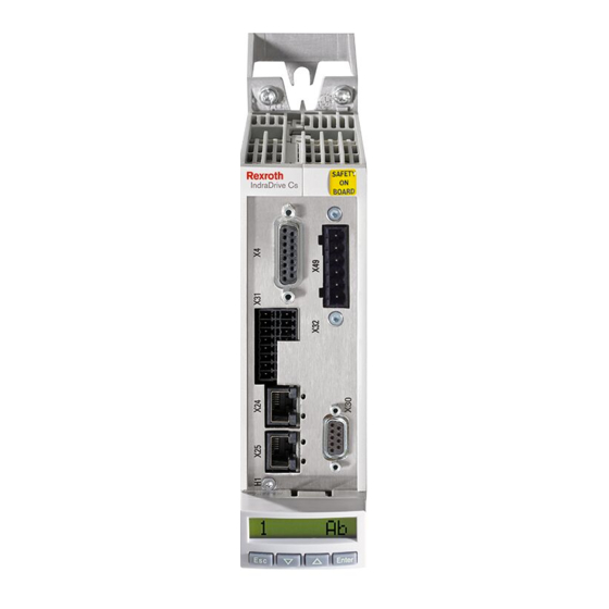
Одноосевые сервопреобразователи серии IndraDrive Cs от компании Bosch Rexroth предназначены для управления движением серводвигателей малой мощности (менее 1 кВт) и до верхнего предела в 9 кВт. Для них характерна высокая стойкость к перегрузкам, силовые и контрольные блоки объединены в одном корпусе, компактная архитектура, подходящая для размещения в условиях ограниченного пространства.
Связь между компонентами осуществляется по средствам технологий обмена данными Ethernet и Sercos III, а также доступен широкий спектр альтернативных типов интерфейсов. Управление осуществляется как с пульта на лицевой панели, так и удаленно посредством программного обеспечения для ПК. Для обеспечения защиты оборудования приводной системы и обслуживающего персонала предприняты соответствующие меры безопасности, а также интегрированы функции безопасного снятия крутящего момента и контроля тормозного блока.
Ассортимент серии состоит из десяти моделей представленных в трех номиналах сетевого питания и трех габаритных форматах исполнения. В зависимости от возлагаемых требований выпускаются три версии блоков управления: экономичный, базовый и продвинутый. Охлаждение воздушное с естественным или принудительным вентилированием.
Отличное решение для сборочных, погрузочно-разгрузочных, упаковочных работ, для привода небольших станков, для нужд пищевой промышленности, печати, производства полупроводников и т. д.
Технические характеристики преобразователей Bosch Rexroth серии IndraDrive Cs (HCS01)
- Напряжение питания: 1AC 110 — 230 В, 3AC 110 — 230 В и 200 — 500 В;
- Мощность электродвигателя: 0,15 — 9 кВт;
- Выходной ток: 3,3 — 54 А;
- Конфигурация: одноосевой;
- Выходная частота: 0 — 1600 Гц;
- Класс защиты корпуса: IP20;
- Встроенные интерфейсы: Sercos III, EtherCAT, EtherNet/IP, PROFIBUS DP, PROFINET IO, CANopen;
- Обратная связь: моторные энкодеры серий MSM и MSK, поддержка HIPERFACE, EnDat 2.1, SSI, датчики Холла, ресиверы и другие;
- Средства для визуализации и настройки: дисплей с кнопочной навигацией, программное обеспечение для удаленной работы;
- Особенности: встроенные функции безопасного отключения крутящего момента, безопасного управления стояночным тормозом, безопасного движения, масштабирование системы обработки данных, свободно конфигурируемые цифровые входы, подключение к шине DC, управление работой вентилятора и другие.
Конфигурация входов/выходов HCS01
- аналоговые: 1 вход;
- цифровые: 8 входов.
Опциональные модули привода HCS01
- Эмуляция энкодера.
- Мульти-интерфейс для подключения нескольких энкодеров.
- Дополнительные модули безопасности.
Параметры типоразмеров электроприводов HCS01
напряжение питания 110 — 230 В, 1 / 3 фазы
|
Тип привода |
Ток, А |
Мощность мотора, кВт |
|
HCS01.1E-W0003-A-02 |
3,3 |
0,15 |
|
HCS01.1E-W0006-A-02 |
6,0 |
0,25 |
|
HCS01.1E-W0009-A-02 |
9,0 |
0,46 |
|
HCS01.1E-W0013-A-02 |
13 |
0,8 |
|
HCS01.1E-W0018-A-02 |
18 |
1,8 |
напряжение питания 200 — 500 В, 3 фазы
|
Тип привода |
Ток, А |
Мощность мотора, кВт |
|
HCS01.1E-W0005-A-03 |
5 |
0,46 |
|
HCS01.1E-W0008-A-03 |
8 |
0,86 |
|
HCS01.1E-W0018-A-03 |
18 |
1,7 |
|
HCS01.1E-W0028-A-03 |
28 |
2,6 |
|
HCS01.1E-W0054-A-03 |
54 |
9,0 |
Купить сервопреобразователи IndraDrive Cs (HCS01) производства Bosch Rexroth, узнать цену и больше информации о продуктах Вы можете обратившись к нашим специалистам.