RM3 Specialty Relays
®
File 8430
RM3 Specialty Relays
Table of Contents
Contents
RM3 Measurement and Control Relays ………………………………………………………. 2-5
RM3JA2 Current Measurement Relays ……………………………………………………….. 6-9
RM3JA1 Current Measurement Relays ……………………………………………………. 10-13
RM3UA2 Voltage Measurement Relays …………………………………………………… 14-17
RM3UA1 Voltage Measurement Relays …………………………………………………… 18-21
RM3TG2 3-Phase Supply Relays ……………………………………………………………. 22-25
RM3TR1 3-Phase Supply Relays ……………………………………………………………. 26-29
RM3TA2 3-Phase Supply Relays…………………………………………………………….. 30-33
RM3TAR1 3-Phase Supply Relays ………………………………………………………….. 34-37
RM3LG2 Liquid Level Control Relay ………………………………………………………… 38-41
RM3LA1 Liquid Level Control Relay ………………………………………………………… 42-45
RM3PA1 Insulation Control Relay ……………………………………………………………. 46-49
RM3EA1 Sensitive Contact Protection Relay ……………………………………………. 50-53
1
RM3 Specialty Relays
Selection guide
Applications
Current measurement
Overcurrent
Voltage measurement
Undercurrent and overcurrent
Overvoltage Undervoltage or overvoltage
3-phase supply control
Measurement or control
Supply voltage
Number of output relay contacts
Output relay state
Display
Built-in time delay
Width
2
Catalog Number
Pages
Adjustable threshold Adjustable thresholds Adjustable thresholds
0.003 to 1 A 0.003 to 1 A or 0.3 to 15 A
0.05 to 5 V or 1 to 100 V depending on relay or 30 to 500 V depending on relay
Detects: proper phase rotation and phase loss
24 Vac
42 to 48 Vac
110 to 130 Vac
220 to 240 Vac
1 Form C
24 to 240 Vac or dc
110 to 130 Vac
220 to 240 Vac
380 to 415 Vac
24 Vac
42 to 48 Vac
110 to 130 Vac
220 to 240 Vac
2 Form C 1 Form C
24 to 240 Vac or dc
110 to 130 Vac
220 to 240 Vac
380 to 415 Vac
220 to 500 Vac
2 Form C 2 Form C
Energized when threshold is exceeded De-energized on detection of a fault
Green LED : Supply voltage is present to the relay
Yellow LED : Relay has been energized.
Yellow LED : Relay has been energized
Fixed 80 ms
.89 inches
22.5 mm
RM3JA2
6 to 9
Adjustable
0.05 to 30 s
1.77 inches
45 mm
RM3JA1
10 to 13
Fixed 80 ms
.89 inches
22.5 mm
RM3UA2
14 to 17
Adjustable
0.05 to 30 s
1.77 inches
45 mm
RM3UA1
18 to 21
None
.89 inches
22.5 mm
RM3TG2
22 to 25
Liquid level control
RM3 Specialty Relays
Selection guide
Insulation control
Protection of sensitive contacts
Control : rotational direction and total failure of
Control : asymmetry of phases, failure one or more phases, of one or more undervoltage, phases rotational overvoltage, 220 direction of phases.
400, 500, 380 to 420 220 to 240 V
430 to 500V 380 to 415 V
Control : asymmetry of phases, phase failure, rotational direction of phases,
220 to 240 V
380/415V to 500V
110 to 130 Vac
160 to 300 Vac
220 to 240 Vac
300 to 500 Vac
380 to 415 Vac
220 to 240 Vac
380 to 415 Vac
110 to 130 Vac
220 to 240 Vac
380 to 415 Vac
2 Form C 1 Form C 2 Form C
Measurement of liquid resistance by submersible probes
24 Vac
110 to 130 Vac
220 to 240 Vac
380 to 415 Vac
1 Form C
24 to 240 Vac or dc
110 to 130 Vac
220 to 240 Vac
380 to 415 Vac
2 Form C
Adjustable threshold
1 to 110 k
Ω
Control of contact closing
24 to 240 Vac or dc
110 to 130 Vac
220 to 240 Vac
24 Vac
110 to 130 Vac
220 to 240 Vac
380 to 415 Vac
1 Form C 2 Form C
De-energized on detection of a fault
Green LED :
Supply voltage is present.
Yellow LED :
Relay has been energized.
3 red LEDs : faults have occurred.
Adjustable
0.1 to 10 s
1.77 inches
45 mm
RM3TR1
26 to 29
Yellow LED :
Relay has been energized.
Fixed 500 ms
.89 inches
22.5 mm
RM3TA2
30 to 33
Green LED :
Supply voltage is present.
Yellow LED :
Relay has been energized.
2 red LEDs : faults have occurred.
Adjustable
0.1 to 10 s
1.77 inches
45 mm
RM3TAR1
34 to 37
Fixed
250 ms
.89 inches
22.5 mm
RM3LG2
38 to 41
Energized when high level electrode immersed.
De-energized when low level electrode not immersed.
Energized when high level electrode immersed.
De-energized when low level electrode not immersed.
Energized on detection of a fault.
Green LED :
Supply voltage is present.
Yellow LED :
Relay has been energized.
Green LED : Supply voltage is present.
Yellow LED : Relay has been energized.
Adjustable
0.1 to 10 s
1.77 inches
45 mm
RM3LA1
42 to 45
None
1.77 inches
45 mm
RM3PA1
46 to 49
None or adjustable
0.05 to 30 s
1.77 inches
45 mm
RM3EA1
50 to 53
3
RM3 Specialty Relays
General Application Data
Environment
Conforming to standards
Approvals
Ambient air temperature around the device
Storage
Operation
On-load factor
Supply voltage range
Insulation voltage
Vibration resistance
Shock resistance
Degree of protection
Settings
Operating status indication
Connection
Wire Combinations
Between input and output
Conforming to IEC 68-2-6
Conforming to VDE 0106
(part 100) and VBG 4 for the terminal block
Terminals
Enclosure
Direct
Green LED on
Yellow LED on
Red LED on
By captive recessed
+/- screws
Stranded wire
Mounting positions
Mounting method
Cover accessory
Housing, terminal covers and top cover material
Product Carton
Clip-on
Optional
Self-extinguishing plastic
Output relay characteristics
Mechanical durability
Minimum switching capacity
Galvanic separation between input and measurement circuits
In millions of operating cycles
Resistive circuit
˚F
(˚C)
˚F
(˚C) kV
AWG
(mm 2 )
IEC 801 part 1-4 level III
IEC 68 part 2-3/2-6
VDE 0435 part 303, 4.8.3/class II and 303, 4.2.1/class I min. 2.5 kV
VDE 57160 part 0160/5.84 paragraph 4.8.8
VDE 0110/overvoltage category III
UL listed file E39281 guide E164353
CSA, GV
-40 to 185
(-40 to 85)
-13 to 140
(-25 to 60)
100%
-15% to +10% of rated supply voltage
2.5
10 gn/F = 55 Hz/a =
±
0.95 mm 2h per level
10 gn
IP 20 protected against direct finger contact
IP 50
By absolute scales
Supply voltage is present to terminals A1 and A2
Output relay has been energized
Indicate that a fault has occurred
All products
≤
2 #14 (
≤
2 x 2.5) without cable end
≤
2 #14 (
≤
2 x 2) with cable end
Any
On 35mm DIN3 mounting track
To reduce the chance of unauthorized changing of settings
Class V0 or V1 (UL 94)
Recyclable
30
17 V and 10 mA
All products
4
RM3 Specialty Relays
RM3 Measurement and Control Relays
General Application Data
Output characteristics
Load on a.c. supply
Load on d.c. supply
Electrical durability of contacts, in millions of operating cycles
220 V 50 Hz AC-1, 360 operating cycles/hour
Millions of operating cycles
10
6
9
8
7
6
5
4
3
2
10
5
1 2 3 4 5 6 7 8
Amperes
Reduction factor K for inductive loads (to be applied to the values obtained above)
1.0
0.9
0.8
0.7
0.6
0.5
100
80
60
50
40
30
20
0.1
0.2
0.3
0.4
0.5
0.6
0.7
0.8
0.9
1.0
Cos ϕ
Load limit curve (resistive load)
V
300
200
10
0.1
0.3
0.5
0.8
2 3 4 6 8 10
0.2
0.4
0.6
1 Amperes
Note: When used with a d.c. contactor or relay, it is recommend that a freewheel diode be connected in parallel to the coil.
+
RM3
K
–
5
RM3 Specialty Relays
RM3JA2 Current Measurement Relays
Operating Principles
RM3JA2
This device is used anywhere it is important to detect when a preset a.c. or d.c. current threshold is exceeded. This relay can be used to monitor currents between 3mA and 1A. Some examples of applications for this relay are:
— To detect whether a conveyor is loaded or not.
— To detect a load on a pump.
— To detect a fan belt breaking.
— To monitor loading of single phase motors.
— To monitor heating and lighting circuits.
Operating principles
• Apply the appropriate supply voltage (U supply) to terminals A1 and A2. This supplies power to the electronics inside this device.
• The current to be monitored is connected to terminal B1 or B2 or B3 (depending on current to be monitored) and terminal C.
• The output relay terminal (15-common, 16-normally close contact, 18-normally open contact) is used to signal that the current is or is not above the preset current threshold setting.
• The current threshold setting (IS1)(refer to the diagrams below) is set to the current above which it is desired to have the output relays change state.
• The hysteresis needs to be set. Hysteresis is the difference between the current threshold setting and the dropout current setting (IS2) of the output relay. It is expressed as a percentage: h= (IS1 — IS2)/IS1
RM3 JA2
R
U
A1 A2
16
15 18
1
2
1 Hysteresis setting, 5 to 30%
2 Current threshold setting (IS1)
If the current to be monitored is connected to:
• B1 and C = Use the white scale times 0.001
(3 to 30mA)
• B2 and C = Use the yellow scale times 0.001
(10 to 100mA)
• B3 and C = Use the yellow scale times 0.01
(0.1 to 1A)
R The yellow LED labeled with an R indicates that the output contacts have been energized when it is illuminated.
U The green LED labeled with a U (Voltage) indicates that supply voltage is present to the RM3 relay when illuminated.
Functional diagram
U supply A1-A2
IS1
IS2
Current measured
Relay 15-18
15-16 t : measurement cycle t
≤
80 ms < t
B1, B2, B3
RM3-JA2
U drop < 1 V
1 measurement
C
Load
• If the supply voltage (U supply) is not applied to terminals A1 and A2, the output relays will be in its deenergized state
(contact 15-16 will be closed and contact 15-18 will be open).
• When supply voltage is applied to terminal A1 and A2, the output relay will not change state until the current has exceeded the current threshold setting (IS1) and the current remains above the current threshold setting (IS1) level for more than the measuring cycle of
≤
80 milliseconds.
• After the output relay has changed state, it will remain energized unless the current falls below the dropout current setting (current threshold setting minus the hysteresis) or supply voltage is lost from terminals A1 or A2 or the measured current exceeds the upper limits of the RM3 relay, which results in damage to the RM3 relay.
• The measure range of this relay can be extended by:
— Using a current transformer and connecting the secondary to the terminals on the RM3 relay.
— Connecting a resistor in parallel with the measuring input (see the next page for an example).
6
RM3 Specialty Relays
RM3JA2 Current Measurement Relays
Wiring, Approximate Dimensions, and Setup Information
Wiring
C
A1 15 B3
B1 B2
C
18 16 A2
Approximate dimensions
A1-A2
B1, B2,
B3, C
15-18
15-16
Supply voltage
Currents to be measured
(see table to the right)
Form C contact of output relay
Connection and current values to be measured
RM3JA211
B1-C
B2-C
3 to 30 mA
10 to 100 mA
B3-C 0.1 to 1 A
Dimensions
Inches
MM
3.94 / 100
Setup information
• Setup example is based on the following information :
.885/22.5
— Overcurrent threshold to be measured is 0.8A.
— Dropout current threshold is 0.6 A.
— The supply voltage is 120 Vac
RM3 JA2
A1 A2
16
15 18
R
U
1
2
• Using page 8, an RM3JA211FG7 relay would be selected because of the
120 Vac supply voltage and it has a measurement range of 3mA to 1A.
• Wire the RM3JA211FG7 relay as explained under operating principles on the previous page.
• Set the current threshold potentiometer (2) to 80 on the yellow scale. Current is being measured on terminals B3 and C, which means you use the yellow scale times 0.01 (80×0.01=0.8A).
• Set the hysteresis potentiometer to 25 h = (IS1-IS2)/IS1
(0.8-0.6)/0.8=0.25 or 25%
• Example of extending the measuring range
RM3-JA
Im
B1
I
Ri
C
Rs
d.c. or a.c. supply:
Simply connect a resistor “Rs” to terminals B1-C (or B2, B3-C) on the measuring input.
The relay energization threshold will be towards the middle of the setting
Ri potentiometer range if the value of Rs is in the region of : Rs =
(2I/Im) — 1 where: Ri Internal resistance of input B1-C
Im Maximum value of the threshold setting range
I Current threshold to be measured
Power dissipated by Rs : P = Rs (I -Im/2)
2
Application : use of relay RM3JA211••• (10 to 100 mA). Connection B2-C to measure a threshold of 1 A, knowing that Ri = 10
Ω
for this rating and that Im = 100 mA
10
(2 x 1/0.1) — 1
Ω
P = (1 —
0.1
2
) 2 x 0.526 = 0.47 W
Select a resistor Rs capable of dissipating at least twice the calculated value, i.e. 1 W for this example, in order to limit the temperature rise.
7
RM3 Specialty Relays
RM3JA2 Current Measurement Relays
Ordering Information
Current to be measured depending on connection ac or dc
3 to 30 mA
10 to 100 mA
0.1 to 1 A
Control Circuit
Voltage
50/60 Hz
24
42-48
110-130
220-240
Catalog
Number
RM3JA211B7
RM3JA211DE7
RM3JA211FG7
RM3JA211MU7
Approximate
Weight
lb. / (kg)
0.39/(0.175)
0.39/(0.175)
0.39/(0.175)
0.39/(0.175)
RM3JA2
Accessories (to be ordered separately)
Description Catalog
Number
Sealing cover
Replacement Marking Tab
LA9RE02
LA9D92
Approximate
Weight lb. / (kg)
0.01/(0.003)
0.01/(0.001)
LA9RE02
8
RM3 Specialty Relays
RM3JA2 Current Measurement Relays
Application Data
Control circuit characteristics
Rated supply voltage (Un)
Average consumption at Un
Vac 50/60 Hz
Vac
V
VA
Output relay and operating characteristics
Number of C/O (Form C) contacts
Output relay state
Rated operational voltage
(switching)
Conventional thermal current
Rated breaking capacity
IEC
UL
IEC
UL
AC-15, 220 V
NEMA
V
V
A
A
A
Time delay
Switching threshold drift
Depending on permissible ambient temperature
Within the supply voltage range
(85% to 110% of Un)
Adjustable
Hysteresis
Measuring cycle
Operating status indication
Green LED on
Yellow LED on
ms
Measuring input characteristics
Internal input resistance and permissible overload depending on the current measurement ranges
Measurement range
Vac 50-60 Hz and Vdc
3 to 30 mA
10 to 100 mA
0.1 to 1 A
24
2.1
42 to 48
2.9
1
Energized when current threshold exceeded
250
300
4
5
1.5
B300
None
≤
0.06 % per degree centigrade
≤
0.5 %
5 to 30 % of the current threshold setting
≤
80
Supply Voltage (Un) is present to the relay.
Relay energized (current threshold exceeded)
Internal input resistance Ri
33
Ω
10
Ω
1
Ω
110 to 130
2.4
220 to 240
3.2
Permissible continuous overload
50 mA
150 mA
1.5 A
Permissible overload for t
≤
3 s
(Not repetitive)
200 mA
0.5 A
5 A
9
RM3 Specialty Relays
RM3JA1 Current Measurement Relays
Operating Principles
RM3JA1
This device is designed to detect when a preset current threshold is exceeded, on a.c. or d.c. supply. The RM3JA1••MW relay can monitor overcurrent or undercurrent. All the other relays can only monitor overcurrent. These relays can be used to monitor currents between 3 mA to 15 A.
Some examples of applications for these relays are:
— To detect whether a conveyor is loaded or not
— To detect a load on a pump
— To detect a fan belt breaking
— To monitor the loading of a single phase motor
— To monitor heating and lighting loads
Operating principles
•
Apply the appropriate supply voltage (U Supply) to terminals A1 and A2. This supplies power to the electronics inside the device.
•
The current to be monitored is connected to terminal B1 or B2 or B3, depending on current to be monitored, and terminal C.
•
The output relay terminals (15 and 25 -Common, 16 and 26 -Normally closed contact, and 18 and 28- Normally open contact) are used to signal that the current is or is not above the preset current threshold setting.
•
The current threshold setting (IS1) (refer to the diagram below) is set to the current above which it is desired to have the output relays change state.
•
The hysteresis needs to be set. Hysteresis is the difference between the current threshold setting and the dropout current setting (IS2) of the output relays. It is expressed as a percentage: h = (IS1-IS2)/IS1. Hysteresis is adjustable between 5 and 30%.
1s
R
U
A1 A2
16
15 18
26
25 28
RM3 JA1
Uc
1
3
4
2
5
1 Time delay range selector switch (0.05 to 1 sec. and 1.5 to
30 sec.).
2 Time delay setting.
3 Hysteresis setting 5 to 30%.
4 Current threshold setting (IS1).
If the current to be monitored is connected to:
• B1 and C = Use the yellow scale times 0.1
• B2 and C = Use the white scale times 1.0
• B3 and C = Use the yellow scale times 1.0
5 Undercurrent (UC) or Overcurrent (OC) selector switch.
This is only available on the RM3JA1
••
MW relay.
R The yellow LED labeled with an R indicates that the output contacts have been energized when it is illuminated.
U The green LED labeled with a U (voltage) indicates that supply voltage is present to the RM3 relay when illuminated.
Functional diagram
• If the supply voltage (U supply) is not applied to terminals A1 and A2, the output relays will be in the de-energized state (Contacts 15-16 and 25-26 will be closed and contacts 15-18 and 25-28 will be open).
• If the RM3JA1••MW set to OC or any of the other RM3JA1 relays monitors a current greater than the threshold setting
(IS1), the output relay will energize with or without time delay, depending on the relay chosen. When the current returns to a value IS2 below the threshold, depending on the hysteresis setting, the relay is instantaneously deenergized.
• If the RM3JA1••MW relay set to UC monitors a current less than the threshold setting IS1, the output relay will energize with or without time delay, depending on the relay chosen. When the current returns to a value IS2 above the threshold, depending on the hysteresis setting, the relay is instantaneously de-energized.
• A measuring cycle lasts only 80 ms, which allows rapid detection of changes in current.
Function «OI» Function «UI»
U supply A1-A2
Relay
IS1
IS2
Current Measured
15-18
15-16
U Supply A1-A2
IS2
Current measured
IS1
Relay
15-18
15-16
25-28
25-26
25-28
25-26 t
< t t
< t t: time delay
B1, B2, B3 C
RM3-JA
Load
U drop < 1 V
Note : The measurement ranges can be extended by means of a current transformer, the secondary of which is connected to the terminals of the corresponding RM3, or by means of a resistor connected in parallel with the current being measured (see the next page for an example).
10
RM3 Specialty Relays
RM3JA1 Current Measurement Relays
Wiring, Approximate Dimensions, and Setup Information
Wiring
C
A1 15 25 B1 B2 B3
16 18 28 26 C A2
Approximate dimensions
A1-A2
B1, B2,
B3, C
15-18
15-16
25-28
25-26
Supply voltage
Currents to be measured
(see table to the right)
1 st Form C contact of output relay
2 nd
Form C contact of output relay
Connection and current values to be measured according to the type of RM3JA1
RM3JA1•1
B1-C 3 to 30 mA
RM3JA1•2
B2-C
B3-C
B1-C
B2-C
B3-C
10 to 100 mA
0.1 to 1 A
0.3 to 1.5 A
1 to 5 A
3 to 15 A
Dimensions
Inches
MM
3.94 / 100 1.77 / 45
Setup information
• Setup example of overcurrent based on the following information:
— Overcurrent threshold to be measured is 13 amperes
— Output relay time delay : 5 sec
— Reset current threshold : 11 A
— Supply voltage : 120 Vac 60 Hz
1s
A1 A2
16
15 18
26
25 28
RM3 JA1
R
U
Uc
1
3
4
2
5
• Using page 12, an RM3JA112MW could be selected because it will work on
120 Vac 60 Hz, it has a range from 0.3 to 15 Amperes, and it has an adjustable time delay.
• Wire the relay as explained under operating principles on the previous page.
• To setup the relay:
Place the function selector 5 on Oc.
— Place the timing range selector 1 on 30 s.
— Set the time delay potentiometer 2 to 5 s on the yellow scale.
— Set the current threshold setting potentiometer 4 to 13 on the yellow scale.
— Set the hysteresis 3 to 15.4 % on the yellow scale.
(13 — 11)/13 = 2/13 = .154 = 15.4 %.
• Extending the measuring range
Im
I RM3-JA
Ri
B1
C
Rs
d.c. or a.c. supply
Simply connect a resistor “Rs” to terminals B1-C (or B2, B3-C) on the measuring input.
The relay energization threshold will be towards the middle of the setting
Ri potentiometer range if the value of RS is in the region of : Rs =
(2I/Im) — 1 where: Ri Internal resistance of input B1-C
I
Im
Maximum value of the threshold setting range
Current threshold to be measured
Power dissipated by Rs : P = Rs (I -Im/2) 2
— Application: use of relay RM3JA111FG7 (10 to 100 mA). Connection B2-C to measure a threshold of 1 A, knowing that Ri = 10 W for this rating and that Im = 100 mA
The value of Rs will be :
10
= 0.526
Ω
(2 x 1/0.1) — 1
0.1
P = (1 — )
2
2
x 0.526 = 0.47 W
Select a resistor “Rs” capable of dissipating at least twice the calculated value, i.e. 1 W for this example, in order to limit temperature rise.
11
RM3 Specialty Relays
RM3JA1 Current Measurement Relays
Ordering Information
RM3JA1
Time delay
Adjustable
0.05 to 30 s
None
Current to be measured depending on connection
Vac or Vdc
3 to 30 mA
10 to 100 mA
0.1 to 1 A
0.3 to 1.5 A
1 to 5 A
3 to 15 A
3 to 30 mA
10 to 100 mA
0.1 to 1 A
0.3 to 1.5 A
1 to 5 A
3 to 15 A
Control Circuit
Voltage
50/60 Hz
24 to 240 Vac or 24 to 240 Vdc
110 to 130 Vac
220 to 240 Vac
380 to 415 Vac
24 to 240 Vac or 24 to 240 Vdc
110 to 130 Vac
220 to 240 Vac
380 to 415 Vac
24 to 240 Vac or 24 to 240 Vdc
110 to 130 Vac
220 to 240 Vac
380 to 415 Vac
24 to 240 Vac or 24 to 240 Vdc
110 to 130 Vac
220 to 240 Vac
380 to 415 Vac
Accessories (to be ordered separately)
Description
Sealing cover
Replacement Marking Tab
Catalog
Number
RM3JA111MW
RM3JA111FG7
RM3JA111MU7
RM3JA111QN7
RM3JA112MW
RM3JA112FG7
RM3JA112MU7
RM3JA112QN7
RM3JA101MW
RM3JA101FG7
RM3JA101MU7
RM3JA101QN7
RM3JA102MW
RM3JA102FG7
RM3JA102MU7
RM3JA102QN7
Catalog
Number
LA9RM301
LA9D92
Weight lb./(kg)
0.65/(0.295)
0.65/(0.295)
0.65/(0.295)
0.65/(0.295)
0.65/(0.295)
0.65/(0.295)
0.65/(0.295)
0.65/(0.295)
0.65/(0.295)
0.65/(0.295)
0.65/(0.295)
0.65/(0.295)
0.65/(0.295)
0.65/(0.295)
0.65/(0.295)
0.65/(0.295)
Weight lb./(kg)
0.01/(0.005)
0.01/(0.001)
LA9RM301
12
RM3 Specialty Relays
RM3JA1 Current Measurement Relays
Application Data
Control circuit characteristics
Rated supply voltage (Un)
Average consumption at Un
Vac 50/60 Hz
Vdc
Vac
Vdc
Output relay and operating characteristics
Number of C/O (Form C) contacts
V
V
VA
W
Output relay state
Rated operational voltage
(switching)
Conventional thermal current
Rated breaking capacity
Time delay
Switching threshold drift
Time delay drift
Hysteresis
Measuring cycle
Operating status indication
IEC
UL
IEC
UL
AC-15
NEMA
Adjustable on
RM3JA11
Depending on permissible ambient temperature
Within the supply voltage range
(85% to 110% Un)
Within the supply voltage range
(85% to 110% Un)
Depending on temperature
Adjustable
V
V
A
A s ms
Green LED on
Yellow LED on
Measuring input characteristics
Internal input resistance and permissible overload depending on the current measurement ranges
Measurement range
Vac 50-60 Hz and Vdc
3 to 30 mA
10 to 100 mA
0.1 to 1 A
0.3 to 1.5 A
1 to 5 A
3 to 15 A
24 to 240
24 to 240
2.2 to 6
2
Internal input resistance Ri
33
Ω
10
Ω
1
Ω
0.06
Ω
0.02
Ω
0.006
Ω
110 to 130
–
4.8
–
2
Energized when current threshold exceeded
400
300
5
5
230 V-3 A, 400 V-2 A
B300
0.05 to 30
≤
0.06 % per degree centigrade
≤
0.5 %
≤
0.5 %
≤
0.06 % per degree centigrade
5 to 30 % of the current threshold setting
≤
80
Supply Voltage (Un) is present to the relay.
Relay energized (current threshold exceeded)
220 to 240
–
3.5
–
380 to 415
–
4
–
Permissible continuous overload
50 mA
150 mA
1.5 A
2 A
7 A
20 A
Permissible overload for t
≤
3 s
200 mA
0.5 A
5 A
10 A
15 A
100 A
13
RM3 Specialty Relays
RM3UA2 Voltage Measurement Relays
Operating Principles
RM3UA2
This device is designed to detect when a preset voltage threshold is exceeded, on a.c. or d.c.
Monitoring is on overvoltage, within a measurement range of 50 mV to 500 V.
Some examples of applications for these relays are:
— d.c. motor overspeed control,
— battery monitoring,
— monitoring of a.c. or d.c. supplies.
Operating principles
• Apply the appropriate supply voltage (U Supply) to terminals A1 and A2. This supplies power to the electronics inside this device.
• The voltage to be monitored is connected to terminals B1 or B2 or B3 (Depending on the voltage to be monitored.)
and C.
• The output relay terminals (15 — Common, 16 — Normally closed contact, 18 — Normally open contact) is used to signal that the voltage is or is not above the preset voltage threshold setting.
• The voltage threshold setting (US1) (refer to the diagram below) is set to the voltage above which it is desired to have the output relays change state.
• The hysteresis needs to be set. The hysteresis is the difference between the voltage threshold setting and the dropout voltage setting (US2) of the output relays. It is expressed as a percentage: h= (US1/US2)/US1. Hysteresis is adjustable between 5 and 30%.
RM3 UA2
A1 A2
16
15 18
R
U
1
2
1 Hysteresis setting 5 to 30%.
2 Voltage threshold setting (US1).
R The yellow LED labeled with an R indicates that the output contact has been energized when it is illuminated.
U The green LED labeled with a U (Voltage) Indicates that supply voltage is present to the RM3 relay when illuminated.
Functional diagram
•
If the supply voltage is not applied to terminals A1 and A2, the output relays will be in the deenergized state (Contacts
15-16 will be closed and contacts 15-18 will be open).
The voltage to be monitored is connected to terminals B1, B2 or B3 and C.
•
When supply voltage is applied to terminal A1 and A2, the output relay will not change state until the voltage has exceeded the voltage threshold setting (US1) and the voltage remains above the voltage threshold setting (US1) level for more than the measuring cycle of <80 milliseconds.
•
After the output relay has changed state, it will remain energized unless the voltage falls below the dropout voltage setting (voltage threshold setting minus the hysteresis) or the supply voltage is lost from terminals A1 and A2 or the measured voltage exceeds the upper limits of the RM3 relay, which results in damage to the RM3 relay.
Functional diagram
U supply A1-A2 t : measuring cycle
US1
US2
Voltage measured
Relay 15-18
15-16 t
≤
80 ms < t
The measurement ranges can be extended beyond 500 V by adding a resistor on model RM3UA213.
Voltage a or c
Simply connect an additional resistor (Rs) in series with measuring input B3.
RM3-UA213
B3
Ri
C
Rs
U > 500 V
If the value of Rs is in the region of :
2 U
Um
Ri : internal resistance seen from input B3/C
Um : maximum value of the threshold setting range
U : voltage threshold to be measured
The relay energization threshold will be towards the middle of the threshold setting potentiometer travel.
In general, the power consumed by the resistor does not exceed 0.5 W.
Note :The measurement range on Vac supply can be extended by means of a voltage transformer, the secondary of which is connected to the measuring terminals of the corresponding RM3.
14
Wiring
C
A1 15 B3
B1 B2
C
18 16 A2
Approximate dimensions
RM3 Specialty Relays
RM3UA2 Voltage Measurement Relays
Wiring, Approximate Dimensions, and Setup Information
A1-A2
B1, B2
B3, C
15-18
15-16
Supply voltage
Voltages to be measured
(see table to the right)
Form C contact of output relay
Connection and voltage values to be measured according to the type of RM3UA2
RM3UA211
B1-C
B2-C
50 to 500 mV
0.3 to 3 V
RM3UA212
RM3UA213
B3-C
B1-C
B2-C
B3-C
B2-C
B3-C
0.5 to 5 V
1 to 10 V
5 to 50 V
10 to 100 V
30 to 300 V
50 to 500 V
Dimensions
Inches
MM
3.94 / 100
Setup information
• Example of overvoltage to be measured:
— Overvoltage threshold to be measured 460 V
— Reset voltage threshold 410 V
— Supply voltage 120 V ac 50/60 Hz
.885/22.5
RM3 UA2
A1 A2
16
15 18
R
U
1
2
• Product selected is a RM3UA213FG7 from page 16.
— Voltage measurement range 30 to 500 V
— Connection of voltage to be measured B3-C (50 to
500 V)
• Measuring principle :
— Set the voltage threshold setting potentiometer 2 to
46
(46 x 10 = 460).
— Set the hysteresis 1 to 10.8 %
(460-410) / 460 = .108 = 10.8%
15
RM3 Specialty Relays
RM3UA2 Voltage Measurement Relays
Ordering Information
RM3UA2
Voltage to be measured depending on connection
Vac or Vdc
50 to 500 mV
0.3 to 3 V
0.5 to 5 V
1 to 10 V
5 to 50 V
10 to 100 V
30 to 300 V
50 to 500 V
Control Circuit
Voltage
50/60 Hz
24
42 to 48
110 to 130
220 to 240
24
42 to 48
110 to 130
220 to 240
24
42 to 48
110 to 130
220 to 240
Accessories (to be ordered separately)
Description
Sealing cover
Replacement Marking Tab
Catalog
LA9RE02
LA9D92
Catalog
Number
RM3UA211B7
RM3UA211DE7
RM3UA211FG7
RM3UA211MU7
RM3UA212B7
RM3UA212DE7
RM3UA212FG7
RM3UA212MU7
RM3UA213B7
RM3UA213DE7
RM3UA213FG7
RM3UA213MU7
Weight
lb./ (kg)
0.43/(0.195)
0.43/(0.195)
0.43/(0.195)
0.43/(0.195)
0.43/(0.195)
0.43/(0.195)
0.43/(0.195)
0.43/(0.195)
0.43/(0.195)
0.43/(0.195)
0.43/(0.195)
0.43/(0.195)
Weight
lb. / (kg)
0.01/(0.003)
0.01/(0.001)
LA9RE02
16
RM3 Specialty Relays
RM3UA2 Voltage Measurement Relays
Application Data
Control circuit characteristics
Rated supply voltage (Un)
Average consumption at Un
Vac 50-60 Hz
Vac
V
VA
Output relay and operating characteristics
Number of C/O (Form C) contacts
Output relay state
Rated operational voltage
(switching)
Conventional thermal current
Rated breaking capacity
IEC
UL
IEC
UL
AC-15, 220 V
NEMA
V
V
A
A
A
Time delay
Switching threshold drift
Depending on permissible ambient temperature
Within the supply voltage range
(85% to 110% of Un)
Adjustable
Hysteresis
Measuring cycle
Operating status indication
Green LED on
Yellow LED on
ms
Measuring input characteristics
Internal input resistance and permissible overload depending on the voltage measurement ranges
Measurement range
Vac 50-60 Hz and Vdc
50 to 500 mV
0.3 to 3 V
0.5 to 5 V
1 to 10 V
5 to 50 V
10 to 100 V
30 to 300 V
50 to 500 V
24
2.1
Internal input resistance Ri
7.7 k
Ω
46.5 k
Ω
77.5 k
Ω
19 k
Ω
95 k
Ω
190 k
Ω
570 k
Ω
950 k
Ω
42 to 48
2.9
1
Energized when voltage threshold exceeded
250
300
4
5
1.5
B300
None
≤
0.06 % per degree centigrade
≤
0.5 %
5 to 30 % of the voltage threshold setting
≤
80
Supply Voltage (Un) is present to the relay.
Relay energized (voltage threshold exceeded)
110 to 130
2.4
220 to 240
3.2
Permissible continuous overload
20 V
60 V
80 V
90 V
150 V
300 V
400 V
550 V
Permissible overload for t
≤
1 s
25 V
80 V
100 V
100 V
200 V
400 V
500 V
550 V
17
RM3 Specialty Relays
RM3UA1 Voltage Measurement Relays
Operating Principles
RM3UA1
This device is designed to detect when a preset voltage threshold is exceeded, on a.c. or d.c. supply. Monitoring is on overvoltage or undervoltage, within a measurement range of 50 mV to 500 V.
Applications :
— d.c. motor overspeed control,
— battery monitoring,
— monitoring of a.c. or d.c. supplies.
Operating principles
• Apply the appropriate supply voltage (U Supply) to terminals A1 and A2. This supplies power to the electronics inside this device.
• The voltage to be monitored is connected to terminals B1 or B2 or B3 (Depending on the voltage to be monitored.) and C.
• The output relay terminals (15 & 25 — Commons, 16 & 26 — Normally closed contacts, 18 & 28 — Normally open contacts) are used to signal that the voltage is or is not above the preset voltage threshold setting.
• Relay set for overvoltage detection (OV) :
If the voltage is greater than the threshold setting US1, the output relay is energized with or without time delay. When the voltage returns to a value US2 below the threshold, depending on the hysteresis setting, the relay is instantaneously de-energized.
• Relay set for undervoltage detection (UV) :
If the voltage is less than the threshold setting US1, the output relay is energized with or without time delay. When the voltage returns to a value US2 above the threshold, depending on the hysteresis setting, the relay is deenergized.
• The hysteresis needs to be set . The hysteresis is the difference between the voltage threshold setting and the dropout voltage setting (US2) of the output relays. It is expressed as a percentage: h= (US1/US2)/US1. Hysteresis is adjustable between 5 and 30 %.
• A measuring cycle lasts only 80 ms, which allows rapid detection of changes in voltage.
1s
A1 A2
16
15 18
26
25 28
RM3 UA1
1
3
1 Time delay range selector switch (0.05 to 1 s or 1.5 to 30 s).
2 Time delay setting.
3 Hysteresis setting 5 to 30 % (1).
4 Voltage threshold setting.
5 Undervoltage (UV) or overvoltage (OV) setting selector.
4
R
U
UV
2
5
R The yellow LED labeled with an R indicates that the output contacts have been energized when it is illuminated.
U The green LED labeled with a U (Voltage) indicates that the supply voltage is present to the RM3 relay when illuminated.
(1) Value of the voltage differential between energization and de-energization of the output relay (% of the voltage threshold to be measured).
Functional diagram
Function «OV»
U supply A1-A2
Function «UV»
US1
US2
Voltage measured
15-18
15-16
Relay
25-28
25-26 t : time delay t < t
U supply A1-A2
US2
US1
Voltage measured
15-18
15-16
Relay
25-28
25-26 t < t
The measurement ranges can be extended beyond 500 V by adding a resistor on models RM3UA103 and RM3UA113.
Voltage a or c
RM3-UA
103 ou
UA 113
Ri
C
Rs
U > 500 V
Simply connect an additional resistor (Rs) in series with the measuring input B3 or C. If the value of Rs is in the region of :
Ri : internal resistance seen from input B3/C
B3
Um
Um : maximum value of threshold setting range
U : voltage threshold to be measured
The relay energization threshold will be towards the middle of the threshold setting potentiometer travel. In general, the power consumed by the resistor does not exceed 0.5 W
Note :The measurement range on Vac supply can be extended by means of a voltage transformer, the secondary of which is connected to the measuring terminals of the corresponding RM3.
18
Wiring
C
A1 15 25 B1 B2 B3
16 18 28 26 C A2
Approximate dimensions
RM3 Specialty Relays
RM3UA1 Voltage Measurement Relays
Wiring, Approximate Dimensions, and Setup Information
A1-A2
B1, B2,
B3, C
15-18
15-16
25-28
25-26
Supply voltage
Voltages to be measured
(see table to the right)
1 st C/O (Form C) contact of output relay
2 nd
C/O (Form C) contact of output relay
Connection and voltage values to be measured according to the type of RM3UA1
RM3UA1•1 B1-C
B2-C
50 to 500 mV
0.3 to 3 V
RM3UA1•2
RM3UA1•3
B3-C
B1-C
B2-C
B3-C
B2-C
B3-C
0.5 to 5 V
1 to 10 V
5 to 50 V
10 to 100 V
30 to 300 V
50 to 500 V
Dimensions
Inches
MM
3.94 / 100
Setup information
• Example of undervoltage to be measured :
— Undervoltage threshold to be measured 24 Vdc
— Output relay time delay 20 seconds
— Reset voltage threshold 27 Vdc
— Supply voltage120 Vac 60 Hz
1s
A1 A2
16
15 18
26
25 28
RM3 UA1
R
U
UV
1
3
4
2
5
1.77 / 45
• Using page 20, an RM3UA112FG7 would be selected because it will work on
120 Vac and has a range of 1 to 100 V and has an adjustable time delay of from 0.05 to 30 seconds.
• To set up the relay:
— Place the function selector 5 on UV.
— Place the timing range selector 1 on 30 s.
— Set the potentiometer 2 to 20.
— Set the voltage threshold setting potentiometer 4 to 24 (24 x 1 = 24).
Voltage to be measured would be connected to terminals B2 and C.
— Set the hysteresis 3 to 12.5 % (27 — 24) / 27 = .125 = 12.5%
19
RM3 Specialty Relays
RM3UA1 Voltage Measurement Relays
Ordering Information
RM3UA1
Time delay
Adjustable
0.05 to 30
None
Voltage to be measured depending on connection
50 to 500 mV
0.3 to 3 V
0.5 to 5 V
1 to 10 V
5 to 50 V
10 to 100 V
30 to 300 V
50 to 500 V
50 to 500 mV
0.3 to 3 V
0.5 to 5 V
1 to 10 V
5 to 50 V
10 to 100 V
30 to 300 V
50 to 500 V
Supply Voltage
(Vac 50/60 Hz.)
24 to 240 Vac or Vdc
110 to 130 Vac
220 to 240 Vac
380 to 415 Vac
24 to 240 Vac or Vdc
110 to 130 Vac
220 to 240 Vac
380 to 415 Vac
24 to 240 Vac or Vdc
110 to 130 Vac
220 to 240 Vac
380 to 415 Vac
24 to 240 Vac or Vdc
110 to 130 Vac
220 to 240 Vac
380 to 415 Vac
24 to 240 Vac or Vdc
110 to 130 Vac
220 to 240 Vac
380 to 415 Vac
24 to 240 Vac or Vdc
110 to 130 Vac
220 to 240 Vac
380 to 415 Vac
Accessories (to be ordered separately)
Description
Sealing cover
Replacement Marking Tab
Catalog
Number
RM3UA111MW
RM3UA111FG7
RM3UA111MU7
RM3UA111QN7
RM3UA112MW
RM3UA112FG7
RM3UA112MU7
RM3UA112QN7
RM3UA113MW
RM3UA113FG7
RM3UA113MU7
RM3UA113QN7
RM3UA101MW
RM3UA101FG7
RM3UA101MU7
RM3UA101QN7
RM3UA102MW
RM3UA102FG7
RM3UA102MU7
RM3UA102QN7
RM3UA103MW
RM3UA103FG7
RM3UA103MU7
RM3UA103QN7
Catalog
Number
LA9RM301
LA9D92
.66/(0.300)
.66/(0.300)
.66/(0.300)
.66/(0.300)
.66/(0.300)
.66/(0.300)
.66/(0.300)
.66/(0.300)
.66/(0.300)
.66/(0.300)
.66/(0.300)
Weight lb./(kg)
.66/(0.300)
.66/(0.300)
.66/(0.330)
.66/(0.300)
.66/(0.300)
.66/(0.300)
.66/(0.300)
.66/(0.300)
.66/(0.300)
.66/(0.300)
.66/(0.300)
.66/(0.300)
.66/(0.300)
Weight
lb./(kg)
0.01/(0.005)
0.01/(0.001)
LA9RM301
20
RM3 Specialty Relays
RM3UA1 Voltage Measurement Relays
Application Data
Control circuit characteristics
Rated supply voltage (Un)
Average consumption at Un
Vac 50-60 Hz
Vdc
Vac
Vdc
Output relay and operating characteristics
Number of C/O (Form C) contacts
V
V
VA
W
Rated operational voltage
(switching)
Conventional thermal current
Rated breaking capacity
Time delay on energization
Switching threshold drift
Time delay drift
IEC
UL
IEC
UL
AC-15
NEMA
RM3UA11
RM3UA10
Depending on permissible ambient temperature
Within the supply voltage range
(85 to 110% Un)
Within the supply voltage range
Depending on nominal operating temperature
V
V
A
A sec.
Output relay state
Operating status indication
Green LED on
Yellow LED on
Adjustable
Hysteresis
Measuring cycle
Measuring input characteristics
Internal input resistance and permissible overload depending on the voltage measurement ranges
Measurement range
Vac 50-60 Hz and Vdc
50 to 500 mV
0.3 to 3 V
0.5 to 5 V
1 to 10 V
5 to 50 V
10 to 100 V
30 to 300 V
50 to 500 V
ms
24 to 240
24 to 240
2.2 to 6
2
< 0.5 %
Internal input resistance Ri
7.7
Ω
46.5
Ω
77.5
Ω
19
Ω
95
Ω
190
Ω
570
Ω
950
Ω
110 to 130
–
4.8
–
2
400
300
5
5
230 V-3 A, 400 V-2 A
B300
Adjustable from 0.05 to 30
None
< 0.06 % per degree centigrade
< 0.5 %
< 0.06 % per degree centigrade
Energized when voltage threshold exceeded
Supply Voltage (Un) is present to the relay.
Relay energized (voltage threshold exceeded)
5 to 30 % of the voltage threshold setting
< 80
Permissible continuous overload
20 V
60 V
80 V
90 V
150 V
300 V
400 V
550 V
220 to 240
–
3.5
–
380 to 415
–
4
–
Permissible overload for t < 1 sec.
25 V
80 V
100 V
100 V
200 V
400 V
500 V
550 V
21
RM3 Specialty Relays
RM3TG2 3-Phase Supply Relays
Operating Principles
RM3TG2
This device monitors the presence and rotational direction of the phases in a 3-phase supply under no-load condition.
Applications:
• Connection of moving equipment :
— site equipment (cranes, pumps, conveyors, etc.),
— agricultural equipment,
— refrigerated trucks.
• Protection of persons and equipment against the consequences of reverse running:
— lifting, handling, elevators, escalators, etc.
• Control of sensitive 3-phase supplies.
Operating principle
The voltage of the supply to be monitored, connected to terminals L1, L2, L3 of the relay, also provides its power supply.
In normal operation, the output relay is energized, the yellow LED is on. If a fault occurs — reversal in rotational direction of phases, failure of one or more phases — the relay is de-energized (or cannot energize at switch-on) and the yellow LED goes out.
This relay is specifically designed for control of supplies under no-load conditions.
In the case of a supply under load, a return voltage can be registered by the RM3 in spite of a phase failure, thereby preventing detection of the true fault (phase failure detection threshold U < 60 V).
For control of supplies under load, select an RM3TR or TAR1.
RM3 TG2
L1
L2
L3
16
15 18
26
25 28
R
R The yellow LED labeled with an R indicates that the output contacts have been energized when it is illuminated.
Functional diagram
L1, L2, L3 L1, L3, L2 L1, L2, L3 L2, L3
L1
L1, L2, L3
Relay
15-18
15-16
25-28
25-26
22
RM3 Specialty Relays
RM3TG2 3-Phase Supply Relays
Wiring and Approximate Dimensions
Wiring
15 L3
L2 25
28 26
18 16
Approximate dimensions
L1, L2, L3
L1, L2, L3
15-18
15-16
25-28
25-26
Supply voltage
3-phase voltages to be controlled
(see table to the right)
1 st
C/O (Form C) contact of output relay
2 nd C/O (Form C) contact of output relay
Connection and voltage values to be controlled
RM3TG2
L1-L2-L3 220 to 500 V (50-60 Hz)
Dimensions
Inches
MM
3.94 / 100 .885/22.5
For a voltage equal to or greater than 415 V, a minimum distance of 10 mm must be left between relays if several are mounted side by side.
23
RM3 Specialty Relays
RM3TG2 3 Phase Supply Relays
Ordering Information
Time delay
Seconds
None
RM3TG2
Control and supply voltage
Vac 50-60 Hz
Volts
220 to 500
Catalog
Number
Weight
RM3TG201MS7 lb./(kg)
0.36/(0.165)
Accessories (to be ordered separately)
Description
Sealing cover
Replacement Marking Tab
Catalog
Number
LA9RE02
LA9D92
Weight lb./(kg)
0.01/(0.003)
0.01/(0.001)
LA9RE02
24
RM3 Specialty Relays
RM3TG2 3-Phase Supply Relay
Application Data
Control circuit characteristics
Rated supply voltage (Un)
Average consumption at Un
Vac 50-60 Hz
Phases L1, L2 Vac
Output relay and operating characteristics
Number of C/O (Form C) contacts
V
VA
Output relay state
Rated operational voltage
(switching)
Conventional thermal current
Rated breaking capacity
Time delay
Operating status indication
IEC
UL
IEC
UL
AC-15, 220 V
NEMA
Yellow LED on
A
A
V
V
A
220 to 500
2.2 to 12.5
2
Energized during fault free operation
De-energized or unable to energize on detection of rotational direction fault or phase failure
250
300
4
5
1.5
B300
None
Relay energized
25
RM3 Specialty Relays
RM3TR1 3-Phase Supply Relays
Operating Principles
RM3TR110
RM3TR111, TR113, TR115
TR112, TR114
This multifunction device is designed to monitor the presence and rotational direction of the phases in a three-phase supply, as well as overvoltage (U > Un) or undervoltage (U < Un).
Applications
• Connection of moving equipment:
— site equipment (cranes, pumps, conveyors, etc.),
— agricultural equipment,
— refrigerated trucks.
• Protection of persons and equipment against the consequences of reverse running:
— lifting, handling, elevators, escalators, etc.
Operating principles
The control circuit supply voltage (Usupply) is applied to terminals A1-A2.
Monitoring of the 3-phase supply (Un) is performed on terminals L1, L2, L3.
In normal operation, the output relay is energized, the yellow LED is on.
The output relay is de-energized and the yellow LED goes out if any of the following faults are detected:
• Overvoltage or undervoltage
If the voltage goes outside the range of Un, the output relay is de-energized:
— overvoltage: the red LED > U illuminates,
— undervoltage: the red LED < U illuminates.
When the supply returns to its rated value, the relay is reenergized according to the hysteresis value (5 %) and the corresponding indicator goes out.
A selector switch allows selection of an adjustable 0.1 to 10 second time delay. With function ,this delay will allow the relay to ignore transient “over” and “under” voltages that might occur. With function , all transients above and below are taken into account and re-energization of the relay is delayed.
• Phase failure or incorrect rotational direction of phases
The output relay is de-energized without a time delay in the event of a phase failure or incorrect rotational direction of phases, the red LED “P” illuminates.
The output relay is energized and the fault indicator goes out as soon as the 3-phase supply (Un) returns to normal, (function ) or after a preset time delay, (function ).
R
U
A1 A2
16
15 18
26
25 28
RM3 TR1
U
U
P
3
1
2
4
1
Time delay function selector:
Fault detection delayed.
Fault detection extended.
2
Potentiometer for setting time delay, in seconds.
3
Potentiometer for setting overvoltage.
4
Potentiometer for setting undervoltage.
R
Yellow LED : indicates output relay has been energized when illuminated.
U
Green LED : indicates that supply voltage (Usupply) is present to the RM3 relay when illuminated.
>U Red LED : overvoltage fault exists.
<U Red LED : undervoltage fault exists.
P
Red LED : phase failure or incorrect rotational direction of phases exists.
Functional diagram
Function
U supply A1-A2
+ 10 %
+ 5 %
Un
— 5 %
— 10 %
Voltage measured
15-18
15-16
Relay
25-28
25-26 t t t
< t
RM3TR110
TR112, TR114
1 Depending on the setting of overvoltage potentiometer 3 above.
2 Depending on the setting of undervoltage potentiometer 4 above.
U supply A1-A2
+ 10 %
+ 5 %
Un
— 5 %
— 10 %
Voltage measured
15-18
15-16
Relay
25-28
25-26 t
Function t
RM3TR111, TR113, TR115
< t
26
RM3 Specialty Relays
RM3TR1 3-Phase Supply Relays
Wiring, Approximate Dimensions, and Setup Information
Wiring
A1 15 25 L1 L2 L3
16 18 28 26 A2
Approximate dimensions
A1-A2
L1, L2, L3
15-18
15-16
25-28
25-26
Supply voltage
Supply to be monitored
(see table to the right)
1 st
C/O (Form C) contact of output relay
2 nd C/O (Form C) contact of output relay
Connection and voltage values to be monitored according to the type of RM3TR1
RM3TR110
L1-L2-L3 220 V-50/60 Hz
RM3TR111
RM3TR112
RM3TR113
RM3TR114
RM3TR115
L1-L2-L3
L1-L2-L3
L1-L2-L3
L1-L2-L3
L1-L2-L3
220 V — 50 Hz
380 to 420 V-50/60 Hz
400 V — 50 Hz
430 to 500 V-50/60 Hz
500 V — 50 Hz
Dimensions
Inches
MM
3.94 / 100 1.77 / 45
Setup information
If the supply voltage (Un) is coming from the 3-phase voltage to be monitored, connect A1 to L1, and A2 to L3. When this is done, some faults cannot be displayed: failure of phase L1 or L3 for example.
Example of undervoltage and overvoltage to be monitored :
— Nominal 3-phase voltage to be monitored 480 Vac 60 Hz
— Overvoltage threshold to be monitored : 500 Vac
— Undervoltage threshold to be monitored : 400 Vac
— Control circuit voltage : 480 Vac
• Using page 28, an RM3TR114VS7 relay would be selected.
• Wire the RM3TR114VS7 relay as explained under operating principles on the previous page.
• Connect the 3-phase voltage to be monitored to terminals L1, L2, L3.
• Adjust the overvoltage to be monitored to 500 V by means of potentiometer 3.
• Adjust the undervoltage to be monitored to 400 V by means of potentiometer 4.
R
U
A1 A2
16
15 18
26
25 28
RM3 TR1
U
U
P
3
1
2
4
27
RM3 Specialty Relays
RM3TR1 3-Phase Supply Relays
Ordering Information
RM3TR1
Adjustable voltage threshold relays
Adjustable time delay
Seconds
0.1 to 10
Control voltage
Vac 50-60 Hz
V
160 to 300
Voltage threshold Nominal voltage to be monitored to be monitored
V
220-50/60 Hz
300 to 500
300 to 500
%
min 160 to 220 max 220 to 300 min 300 to 380 max 420 to 500 min 350 to 430 max 500 to 580
380 to 420 50/60 Hz
430 to 500 50/60 Hz
Fixed voltage threshold relays
Adjustable time delay
Seconds
0.1 to 10
Control voltage
Vac 50-60 Hz
V
110 to 130
220 to 240
380 to 415
Voltage threshold Nominal voltage to be monitored to be monitored
%
±
10
±
10
±
10
V
220 — 50 Hz
220 — 50 Hz
220 — 50 Hz
Catalog
Number
RM3TR110GV7
RM3TR112VS7
RM3TR114VS7
Catalog
Number
RM3TR111FG7
RM3TR111MU7
RM3TR111QN7
110 to 130
220 to 240
380 to 415
±
10
±
10
±
10
400 — 50 Hz
400 — 50 Hz
400 — 50 Hz
110 to 130
220 to 240
380 to 415
±
10
±
10
±
10
500 — 50 Hz
500 — 50 Hz
500 — 50 Hz
Accessories (to be ordered separately)
Description
Sealable cover (45mm Width)
Replacement Marking Tab
RM3TR113FG7
RM3TR113MU7
RM3TR113QN7
RM3TR115FG7
RM3TR115MU7
RM3TR115QN7
Catalog
Number
LA9RM301
LA9D92
Weight
lb./(kg)
0.71/(0.320)
0.71/(0.320)
0.71/(0.320)
Weight
lb./(kg)
0.71/(0.320)
0.71/(0.320)
0.71/(0.320)
0.71/(0.320)
0.71/(0.320)
0.71/(0.320)
0.71/(0.320)
0.71/(0.320)
0.71/(0.320)
Weight lb./(kg)
0.01/(0.005)
0.01/(0.001)
LA9RM301
28
RM3 Specialty Relays
RM3TR1 3-Phase Supply Relays
Application Data
Control circuit characteristics
Rated supply voltage (Un)
Average consumption at Un
Vac 50-60 Hz
Vac
V
VA
Output relay and operating characteristics
Number of C/O (Form C) contacts
110 to 130
2.7
2
Output relay state
Rated operational voltage
(switching)
Conventional thermal current
Rated breaking capacity
Time delay
Switching threshold drift
Time delay drift
Hysteresis
Measuring cycle
Operating status display
IEC
UL
IEC
UL
AC-15
NEMA
On overvoltage or undervoltage fault only
Depending on permissible ambient temperature
Within the supply voltage range
(85 to 110 % of Un)
V
V
A
A sec.
Within the supply voltage range
(85 to 110% of Un)
Depending on the rated operational temperature
Fixed
Fixed
U Green LED on
R Yellow LED on
> U Red LED on
< U Red LED on
P Red LED on
ms
Control input characteristics
Nominal voltages to be monitored
Vac 50 Hz
Vac 50-60 Hz
V
V
< 0.5 %
< 0.5 %
220 to 240
2.8
< 0.06 % per degree centigrade
< 0.06 % per degree centigrade
About 5 % of the de-energization threshold
< 80
Supply Voltage (Un) is present to the relay.
Output relay is energized.
An overvoltage situation exists.
An undervoltage situation exists.
Incorrect rotational direction of phases or phase failure exists.
220, 400, 500
220, 380 to 420, 430 to 500
160 to 300
3
380 to 415
3
De-energized on detection of overvoltage, undervoltage or on phase failure or rotational direction of phases fault
400
300
5
5
230 V- 3A, 400 V-2 A
B300
1 to 10
300 to 50
3
29
RM3 Specialty Relays
RM3TA2 3-Phase Supply Relay
Operating Principles
RM3TA2
This device detects:
• A phase imbalance (asymmetry fault) within an adjustable threshold from 5 to 15 % (reduction or increase in voltage of one phase in relation to the other two).
• Failure of one or more phases.
• A phase reversal (Rotational direction of phases fault).
Applications:
• Connection of moving equipment:
— site equipment (cranes, pumps, conveyors, etc.),
— agricultural equipment,
— refrigerated trucks.
• Protection of motors against single-phase operation.
• Control of sensitive 3-phase supplies.
Operating principle
The supply voltage to be monitored is connected to terminals L1, L2, L3 of the relay, it also provides the power for the relay to operate.
In normal operation, the output relay is energized and the yellow LED is on.
When a phase imbalance (asymmetry fault), phase failure or phase reversal (rotational direction fault) is detected, the output relay de-energizes after a fixed time delay of 0.5 seconds (or cannot energize at start up), and the yellow LED goes out.
A fixed hysteresis (1) of 20 % is built-into the relay.
RM3 TA2
L1
L2
L3
16
15 18
1 Phase imbalance (Asymmetry) threshold setting potentiometer, from 5 to 15 %.
R Yellow LED is illuminated when no fault condition exists and the output relay is energized.
1
R
Functional diagram
Asymmetry
Un
Asymmetry
L1, L2, L3
Relay
15-18
15-16 t: time delay
L1, L2, L3 L1, L3, L2 L1, L2
L3
L1, L2
L3
L1
L2
L3
∆
L1/L3 > U asymmetry t = 0.5 s
(1) Hysteresis is the voltage differential (dissymmetry) between energization and de-energization of the output relay (% in relation to the preset asymmetry value).
Example: Phase imbalance is set at 10 %, 480 Vac supply
— relay de-energization threshold: 480 — 10 % = 432 V,
— relay re-energization threshold: 432 V + (20 % x 10 %) of 432 V = 440.6 V.
30
RM3 Specialty Relays
RM3TA2 3-Phase Supply Relay
Wiring and Approximate Dimensions
Wiring
15 L3
L1 L2
18 16
Approximate dimensions
L1, L2, L3
Supply voltage and voltages to be monitored (see table to the right)
15-18
15-16
1 st
C/O (Form C) output relay
Connection and voltage values to be controlled according to the type of RM3TA2
RM3TA210
RM3TA211
RM3TA212
RM3TA213
L1-L2-L3
L1-L2-L3
L1-L2-L3
L1-L2-L3
220 to 240 V — 60 Hz
220 to 240 V — 50 Hz
380 to 415 V — 60 Hz
380 to 415 V — 50 Hz
Dimensions
Inches
MM
3.94 / 100
.885/22.5
31
RM3 Specialty Relays
RM3TA2 3-Phase Supply Relays
Ordering Information
Time delay on de-energization
Seconds
Fixed 0.5
Supply voltage and voltages to be monitored
V
220 to 240 — 60 Hz
220 to 240 — 50 Hz
380 to 415 — 60 Hz
380 to 415 — 50 Hz
Catalog
Number
RM3TA210M6
RM3TA211M5
RM3TA212V6
RM3TA213V5
Weight
lb./(kg)
0.42/(0.190)
0.42/(0.190)
0.42/(0.190)
0.42/(0.190)
RM3TA2
Accessories (to be ordered separately)
Description
Sealing cover (22.5 mm width)
Replacement marking tab
Catalog
Number
LA9RE02
LA9D92
Weight lb./(kg)
0.01/(0.003)
0.01/(0.001)
LA9RE02
32
RM3 Specialty Relays
RM3TA2 3-Phase Supply Relay
Application Data
Control circuit characteristics
Rated supply voltage (Un)
Average consumption at Un
Rated supply and monitoring voltage tolerance
Vac 50/60 Hz
Phases L2, L3 Vac
V
VA
Output relay and operating characteristics
Number of C/O (Form C) contacts
Output relay state
Rated operational voltage
(switching)
Conventional thermal current
Rated breaking capacity
Time delay on de-energization
Switching threshold drift
Hysteresis
Phase imbalance
Operating status indication
IEC
UL
IEC
UL
AC-15, 220 V
NEMA
Fixed
Depending on permissible ambient temperature
Within the supply voltage range
(85 to 110% of Un)
Fixed
Adjustable
Yellow LED on
V
V
A
A
A
Sec.
220 to 240
1.3
+ or — 15 %
380 to 415
1.4
+ or — 15%
1
De-energized on detection of phase imbalance, phase failure or phase reversal.
250
300
4
5
1.5
B300
0.5
< 0.06 % per degree centigrade
< 0.5%
Approximately 20% in relation to phase imbalance threshold.
5 to 15%
Relay is energized
33
RM3 Specialty Relays
RM3TAR1 3-Phase Supply Relay
Operating Principles
RM3TAR1
This device detects:
• A phase imbalance (asymmetry fault) within an adjustable threshold from 5 to 15 % (Reduction or increase in voltage of one phase in relation to the other two.).
• Failure of one or more phases.
• A Phase reversal (Rotational direction of phases fault).
Applications:
• Connection of moving equipment:
— site equipment (cranes, pumps, conveyors, etc.),
— agricultural equipment,
— refrigerated trucks.
• Protection of persons and equipment against the consequences of reverse running: lifting, handling, elevators, escalators, etc.
• Control of sensitive 3-phase supplies.
Operating principle
The supply voltage is connected to terminals A1 and A2.
The 3-phase voltage to be monitored is connected to L1, L2, and L3 of the relay.
In normal operation, the output relay is energized, the yellow and green LEDs are on.
If a phase reversal (rotational direction) or phase failure fault is detected, the relay is de-energized (or cannot energize at start up), the yellow LED goes out, the red LED (P) illuminates.
If a phase imbalance (asymmetry fault) is detected, the output relay de-energizes after a preset time delay between 0.1
and 10 seconds, the yellow LED goes out and the red LED (A) illuminates.
A fixed hysteresis (1) of 20 % is built into the relay.
A1 A2
16
15 18
26
25 28
R
U
RM3 TAR1
A
P
1
2
1
Phase imbalance (Asymmetry) threshold setting potentiometer, from 5 to 15 %.
2
Time delay setting potentiometer, from 0.1 to 10 s.
R
The yellow LED labeled with an R indicates that the output contacts have been energized when it is illuminated.
U
The green LED labeled with a U (Supply voltage) indicates that supply voltage is present to the RM3 relay when illuminated.
A
Red LED: A phase imbalance (dissymmetry) exists.
P
Red LED: A phase failure (2 or 3) exists.
P and A
Red LEDs: A phase reversal (Incorrect rotational direction of phases) exists
Functional diagram
U supply A1-A2
Asymmetry
Un
Asymmetry
L1, L2, L3
L1, L2, L3 L1, L3, L2 L1, L2
L3
L1, L2
L3
L1
L2
L3
∆
L1/L3 > U asymmetry
Relay
15-18
15-16
25-28
25-26 t: time delay t
(1) Hysteresis is the voltage differential (dissymmetry) between energization and de-energization of the output relay.
(% in relation to the preset phase imbalance (asymmetry) value).
Example: asymmetry set at 10 %, 480 Vac supply
— relay de-energization threshold: 480 — 10 % = 432 V,
— relay re-energization threshold: 432 V + (20 % x 10 %) of 432 V = 440.6 V.
34
RM3 Specialty Relays
RM3TAR1 3-Phase Supply Relay
Wiring and Approximate Dimensions
Wiring
A1 15 25 L1 L2 L3
16 18 28 26 A2
Approximate dimensions
A1-A2
25-28
25-26
Supply voltage
L1, L2, L3
3-phase voltages to be monitored
(See table to the right.)
15-18
15-16
1 st
C/O (Form C) contact of output relay
2 nd C/O (Form C) contact of output relay
Connection and voltage values to be controlled according to the type of RM3TAR1
RM3TAR110
L1-L2-L3 220 to 240 V — 60 Hz
RM3TAR111
RM3TAR112
RM3TAR113
RM3TAR114
RM3TAR115
L1-L2-L3
L1-L2-L3
L1-L2-L3
L1-L2-L3
L1-L2-L3
220 to 240 V — 50 Hz
380 to 415 V — 60 Hz
380 to 415 V — 50 Hz
480 to 500 V — 60 Hz
480 to 500 V — 50 Hz
Dimensions
Inches
MM
3.94 / 100 1.77 / 45
35
RM3 Specialty Relays
RM3TAR1 3-Phase Supply Relays
Ordering Information
RM3TAR1
Adjustable time delay
Sec.
0.1 to 10
Voltage to be monitored
V
220 to 240 — 60 Hz
380 to 415 — 60 Hz
480 to 500 — 60 Hz
220 to 240 — 50 Hz
380 to 415 — 50 Hz
480 to 500 — 50 Hz
Supply Voltage
(Vac 50/60 Hz.)
V
110 to 130
220 to 240
110 to 130
220 to 240
380 to 415
110 to 130
220 to 240
380 to 415
480 to 500
110 to 130
220 to 240
380 to 415
110 to 130
220 to 240
380 to 415
110 to 130
220 to 240
380 to 415
Accessories (to be ordered separately)
Description
Sealing cover (45mm width)
Replacement marking tab
Catalog
Number
RM3TAR110FG7
RM3TAR110MU7
RM3TAR112FG7
RM3TAR112MU7
RM3TAR112QN7
RM3TAR114FG7
RM3TAR114MU7
RM3TAR114QN7
RM3TAR114TS7
RM3TAR111FG7
RM3TAR111MU7
RM3TAR111QN7
RM3TAR113FG7
RM3TAR113MU7
RM3TAR113QN7
RM3TAR115FG7
RM3TAR115MU7
RM3TAR115QN7
Catalog
Number
LA9RM301
LA9D92
Weight
lb./(kg)
0.69/(0.315)
0.69/(0.315)
0.69/(0.315)
0.69/(0.315)
0.69/(0.315)
0.69/(0.315)
0.69/(0.315)
0.69/(0.315)
0.69/(0.315)
0.69/(0.315)
0.69/(0.315)
0.69/(0.315)
0.69/(0.315)
0.69/(0.315)
0.69/(0.315)
0.69/(0.315)
0.69/(0.315)
0.69/(0.315)
Weight lb./(kg)
0.01/(0.005)
0.01/(0.001)
LA9RM301
36
RM3 Specialty Relays
RM3TAR1 3-Phase Supply Relay
Application Data
Control circuit characteristics
Rated supply voltage (Un) Vac 50-60 Hz
V
110 to 130 220 to 240 380 to 415
Except for
RM3TAR110
3
480 to 500
RM3TAR114
ONLY
3
Average consumption at Un
Vac
VA
Output relay and operating characteristics
Number of C/O (Form C) contacts
Output relay state
Rated operational voltage
(switching)
Conventional thermal current
Rated breaking capacity
Time delay on de-energization
Switching threshold drift
Time delay drift
Hysteresis
IEC
UL
IEC
UL
AC-15
NEMA
Adjustable
Depending on permissible ambient temperature
Within the supply voltage range
(85 to 110% of Un)
Within the supply voltage range
Depending on nominal operating temperature
Fixed
V
V
A
A
Sec.
Phase asymmetry control
Measuring cycle
Operating status indication
Adjustable
U Green LED on
R Yellow LED on
A Red LED on
P Red LED on
P and A LEDs on
Measuring input characteristics
Monitoring voltage tolerance ms
2.7
2.8
2
De-energizes on detection of a phase imbalance (asymmetry fault), a phase failure or a phase reversal (rotational direction of phases fault).
400
300
5
5
230 V-3 A, 400 V-2 A
B300
0.1 to 10
< 0.06% per degree centigrade
< 0.5%
< 0.5%
< 0.06% per degree centigrade
Approximately 20% in relation to phase imbalance
(asymmetry) threshold
5 to 15%
≤
100
Supply voltage (Usupply) is present to the relay.
Relay is energized
Phase imbalance (asymmetry) fault exists.
Phase failure (2 or 3) exists.
Phase reversal (Incorrect rotational direction of phases or phase failure.)
+ or — 15 %
37
RM3 Specialty Relays
RM3LG2 Liquid Level Control Relay
Operating Principles
RM3LG2
This device monitors the levels of conductive liquids. Do not use with flammable liquids.
It controls the actuation of pumps or valves to regulate the levels and is also suitable for protecting submersible pumps against running empty, or protecting tanks from “overflow”. It can also be used to control dosing of liquids in mixing processes.
• Some examples of liquids in which the RM3LG2 relay can be used:
— spring, town, industrial and sea water
— metallic, acid or basic salt solutions
— liquid fertilizers
— non concentrated alcohol (< 40 %)
— liquids in the food processing industry: milk, beer, coffee, etc.
• Some examples of liquids in which the RM3LG2 relay CAN NOT be used:
— chemically pure water
— fuels, liquid gasses (flammable)
— oil, concentrated alcohol (> 40 %)
— ethylene, glycol, paraffin, varnish and paints
Presentation
RM3 LG2
A1 A2
16
15 18
1
1
Response sensitivity potentiometer (in kW).
R
The yellow LED labeled with an R indicates that the output relays have been energized when it is illuminated.
U
The green LED labeled with a U (Supply voltage) indicates that supply voltage is present to the RM3 relay when illuminated.
R
U
Operating principle
The operating principle is based on a change in the resistance measured between immersed or non immersed electrodes.
The electrodes may be replaced by other sensors or probes which transmit values representing variations in resistance
(Refer to page 39, “Setting-up”).
• 3 electrodes (1)
B1 B2 B3 B1 B2 B3 B1 B2 B3 B1 B2 B3 B1 B2 B3 B1 B2 B3
B2 high level
B2 low level
B1 ground electrode
(reference)
Relay
15-18
15-16
U supply A1-A2
Note: If a metallic tank is used, the ground electrode (B1) can be eliminated by connecting the cable directly to one of the tank’s metallic surfaces.
(1) This product can be used with only 2 electrodes.
In this case, electrode B2 performs both the high level and low level functions. The absence of a time delay can cause oscillation of the output relay (wave effect).
38
RM3 Specialty Relays
RM3LG2 Liquid Level Control Relay
Wiring, Approximate Dimensions, and Setup Information
Wiring
A1 15 B3
B1 B2
18 16 A2
Approximate dimensions
A1-A2
Supply voltage
B1, B2, B3
Electrodes
(see table to the right)
15-18
15-16
C/O (Form C) contact of output relay
Electrodes and levels controlled
B1
B2
B3
Ground electrode
Max. level
Min. level
Dimensions
Inches
MM
3.94 / 100
Setup information
RM3 LG2
A1 A2
16
15 18
R
U
.885/22.5
2-conductor cable in cylindrical sheath
(max. Ø 6.3 mm)
Level electrode
Reference electrode
(skirt)
Set the potentiometer to the minimum value.
Connect the electrodes as shown below.
Apply power to terminals A1 and A2.
When all the electrodes are simultaneously immersed in the liquid to be monitored, slowly turn the potentiometer towards the maximum value (100 W) until the relay is energized. Exceed the tripping threshold of the relay by 10 kW to compensate for variations in the supply voltage. (The relay may already be energized before turning the potentiometer). If the relay will not energize, a more sensitive device must be used (greater ohmic value): see RM3LA1.
Then check that the relay de-energizes correctly as soon as electrodes EH and EB are out of the liquid (see examples below). If the relay does not de-energize, select a less sensitive device (see RM3LA1).
The electrode connection point must be protected against corrosion, by sticking or sealing. In areas where thunderstorms are likely to occur, measures must also be taken to protect the electrode lines.
Probe LA9RM201
This probe is of the “suspended” type. It is coaxial; i.e. in addition to the normal (central) electrode, the stainless steel skirt can also act as ground (reference) electrode, which means that there is no need to install a separate reference probe. In this way, for controlling one level, only one probe is required instead of 2; for controlling 2 levels, only 2 probes are required instead of 3.
The connecting cable must be of the “2-conductor” type with common cylindrical PVC sheath, having a maximum diameter of 6.3 mm. The skirt also acts as a “calming chamber”, so avoiding inaccuracy due to an agitated surface of the liquid (waves).
Maximum operating temperature: 212
°
F (100
°
C).
Connection examples
Control by electrodes
A1 15 B1 B2 B3
EH
High level
Low level
Control by probes
RM3-LG2
B2
B3
B1
B2
B1
M
EB
EB
M
EH EH
M
16 18 A2
2 levels 1 level
EH = High level electrode
EB = Low level electrode
M = Reference electrode (common)
39
RM3 Specialty Relays
RM3LG2 Liquid Level Control Relay
Ordering Information
Liquid level relay
Fixed time delay
ms
250
Sensitivity
Scale
Ω
5 to 100
Control Circuit
Voltage 50/60 Hz
V
24
110 to 130
220 to 240
380 to 415
Catalog
Number
RM3LG201B7
RM3LG201FG7
RM3LG201MU7
RM3LG201QN7
Weight
lb./(kg)
0.43/(0.195)
0.43/(0.195)
0.43/(0.195)
0.43/(0.195)
RM3LG2
Liquid level control probe
Type of installation
Suspended by cable
Maximum operating temperature
212
°
F (100
°
C)
Catalog
Number
LA9RM201
Weight lb./(kg)
0.22/(0.100)
LA9RM201
Accessories (to be ordered separately)
Description
Sealing cover (22.5mm width)
Replacement Marking Tab
Catalog
Number
LA9RE02
LA9D92
Weight lb./(kg)
0.01/(0.003)
0.01/(0.001)
LA9RE02
40
RM3 Specialty Relays
RM3LG2 Liquid Level Control Relays
Application Data
Control circuit characteristics
Rated supply voltage (Un)
Average consumption at Un
Vac 50-60 Hz
Vac
Output relay and operating characteristics
Number of C/O (Form C) contacts
Output relay state
V
VA
24
1.9
110 to 130
2.6
220 to 240
2.4
380 to 415
2.9
Rated operational voltage
(switching)
Conventional thermal current
Rated breaking capacity
Time delay
Operating status indication
IEC
UL
IEC
UL
AC-15, 220 V
NEMA
Fixed
U Green LED on
R Yellow LED on
V
V
A
A
A ms
300
4
5
1.5
1
Energized when the high level electrode is immersed and de-energized when the low level electrode is no longer immersed
250
B300
250
Supply Voltage (U supply) is present to the relay.
Output relay is energized.
Electrode circuit characteristics (1)
Sensitivity scale
Maximum electrode voltage
Maximum electrode current
Adjustable
Vac
Ω
V mA
5 to 100
30
1
Maximum cable capacity
Maximum cable length nF m
10
100
(1) The electrodes may also be built into the probes. The probes are designed to be either fixed to a tank, by means of a bracket with a seal (closed tanks), or suspended by their own electrical connecting cable (bore holes, etc.).
Refer to “Setting-up” (Probe LA9RM201) section on page 39.
41
RM3 Specialty Relays
RM3LA1 Liquid Level Control Relay
Operating Principles
RM3LA1
This device monitors the levels of conductive liquids. Do not use with flammable liquids.
It controls the actuation of pumps or valves to regulate the levels.
It is also suitable for protecting submersible pumps against running empty, or protecting tanks from “overflow”. It can also be used to control dosing of liquids in mixing processes.
• Some examples of liquids in which the RM3LA1 can be used with:
— spring, town, industrial and sea water
— metallic, acid or basic salt solutions
— liquid fertilizers
— non concentrated alcohol (< 40 %)
— liquids in the food processing industry : milk, beer, coffee, etc.
• Some examples of liquids in which the RM3LA1 CAN NOT be used with:
— chemically pure water
— fuels, liquid gasses (flammable)
— oil, concentrated alcohol (> 40 %)
— ethylene, glycol, paraffin, varnish and paints
RM3 LA1
1
Selector for time delay on energization or on de-energization of the relay.
1
2
0.1 to 10 second time delay potentiometer.
A1 A2
16
15 18
26
25 28
3
3
Sensitivity range adjustment (5k, 50k or 500k).
4
2
4
Fine sensitivity adjustment
5k range (potentiometer setting times 0.1).
50k range (potentiometer setting times 1).
500k range (potentiometer setting times 10).
R
U
U
The green LED labeled with a U (Supply voltage) indicates that the supply voltage is present to the RM3 relay when illuminated.
R
The yellow LED labeled with an R indicates that the output relay is energized when it is illuminated.
Operating principle
The operating principle is based on a change in the resistance measured between immersed or non immersed electrodes.
The electrodes may be replaced by other sensors or probes which transmit values representing variations in resistance
(Refer to page 43, “Setting-up”).
Time delay on filling (1) Time delay on emptying (1)
• 2 electrodes
Max. level
Min. level
B1 B2 B1 B2 B1 B2 B1 B2 B1 B2 B1 B2
2 Form C relay
U supply A1-A2
15-18
15-16
25-28
25-26 t t
• 3 electrodes
B1 B2 B3 B1 B2 B3 B1 B2
B3
B1 B2
B3
B1 B2 B3 B1 B2 B3
Max. level
Min. level
Ground electrode
(reference)
15-18
15-16
2 Form C relay (1)
25-28
25-26
U supply A1-A2 t t
Note : If a metallic tank is used, the ground electrode (B1) can be eliminated by connecting the cable directly to one of the tank’s metallic surfaces.
(1) Level exceeded, see page 43 “Setting-up”.
42
RM3 Specialty Relays
RM3LA1 Liquid Level Control Relay
Wiring, Approximate Dimensions, and Setup Information
Wiring
A1 15 25 B1 B2 B3
16 18 28 26 A2
Approximate dimensions
A1-A2
B1, B2, B3
15-18
15-16
25-28
25-26
Supply voltage
Electrodes
(see table to the right)
1 st C/O (Form C) contact of output relay
2 nd
C/O (Form C) contact of output relay
Electrodes and levels controlled
B1
Ground electrode
B2
B3
Max. level
Min. level
Dimensions
Inches
MM
3.94 / 100
Setup information
A1 A2
16
15 18
26
25 28
RM3 LA1
R
U
2-conductor cable in cylindrical sheath
(max. Ø 6.3 mm)
Level electrode
Reference electrode
(skirt)
1
3
4
2
1.77 / 45
Set potentiometers 4 and 2 to the minimum value and set switch 3 to 5 k.
Connect the electrodes as shown below.
Apply power to terminals A1 and A2.
When all the electrodes are simultaneously immersed in the liquid to be monitored, slowly turn the sensitivity potentiometer 4 towards the maximum value (50) until the relay is energized. (The relay may energize before turning the potentiometer. If it does you are finished with this step.). If the relay will not energize, set potentiometer 4 back to its minimum setting and turn switch 3 to 50k and repeat the above procedure. If the relay still doesn’t energize, set potentiometer 4 back to its minimum setting again and turn switch 3 to 500k and repeat the above procedure. If the relay still doesn’t energize, this relay will not work for the application.
Then make sure the relay de-energizes correctly when electrodes EH and EB are removed from the liquid.
Note : The maximum level EH on a time delay on filling application can be raised by means of the adjustable time delay from 0.1 to 10 seconds, using function . The minimum level EB on a time delay on emptying application can be lowered by means of the adjustment delay from 0.1 to 10 seconds, using function .
The electrode connection point must be sealed to protect against corrosion. In areas where thunderstorms are likely to occur, the electrode lines must be protected.
Probe LA9RM201
This probe is of the “suspended” type. It is coaxial ; i.e. in addition to the normal (central) electrode, the stainless steel skirt can also act as ground (reference) electrode, which means that there is no need to install a separate reference probe. In this way, for controlling one level, only one probe is required instead of 2 ; for controlling 2 levels, only 2 probes are required instead of 3.
The connecting cable must be of the “2-conductor” type with common cylindrical PVC sheath, having a maximum diameter of 6.3 mm. The skirt also acts as a “calming chamber”, so avoiding inaccuracy due to an agitated surface of the liquid (waves).
Maximum operating temperature: 212
°
F (100
°
C).
Control by electrodes
A1 15 25 B1 B2 B3
EH
High level
Low level
Control by probes
RM3-LA1
B2
B3
B1
B2
B1
16 18 28 26 A2
M
EB
EB
M
2 levels
EH EH
M
1 level
EH = High level electrode
EB = Low level electrode
M = Reference electrode (common)
43
RM3 Specialty Relays
RM3LA1 Liquid Level Control Relay
Ordering Information
Liquid level control relays
Adjustable time delay
Sensitivity
Scale
Seconds
0.1 to 10
Ω
250 to 500
Control Circuit
Voltage
(Vac are 50/60 Hz)
24 to 240 Vac or 24 to 240 Vdc
24 Vac
110 to 130 Vac
220 to 240 Vac
380 to 415 Vac
Catalog
Number
RM3LA111MW
RM3LA111B7
RM3LA111FG7
RM3LA111MU7
RM3LA111QN7
Weight
lb./(kg)
0.54/(0.245)
0.54/(0.245)
0.54/(0.245)
0.54/(0.245)
0.54/(0.245)
RM3LA1
Liquid level control probe
Type of installation
Suspension by cable
Maximum operating temperature
212
°
F (100
°
C)
Catalog
Number
LA9RM201
Weight lb./(kg)
0.22/(0.100)
LA9RM201
Accessories (to be ordered separately)
Description
Sealing cover (45mm width)
Replacement Marking Tab
Catalog
Number
LA9RM301
LA9D92
Weight lb./(kg)
0.01/(0.005)
0.01/(0.001)
LA9RM301
44
RM3 Specialty Relays
RM3LA1 Liquid Level Control Relay
Application Data
Control circuit characteristics
Rated supply voltage (Un)
Average consumption at Un
Vac 50-60 Hz
Vdc
Vac
Vdc
Output relay and operating characteristics
Number of C/O (Form C) contacts
V
V
VA
W
24 to 240
24 to 240
2 to 7
2.4
2
24
–
3.1
–
110 to 130
–
2.7
–
220 to 240
–
2.6
–
380 to 415
–
3.4
–
Output relay state
Rated operational voltage
(switching)
Conventional thermal current
Rated breaking capacity
Time delay
Operating status indication
IEC
UL
IEC
UL
AC-15
NEMA
Adjustable
U Green LED on
R Yellow LED on
A
A
V
V sec.
Energized when the high level electrode is immersed and de-energized when the low level electrode is no longer immersed
400
300
5
5
230 V-3 A, 400 V-2A
B300
0.1 to 10
Supply voltage is present to the relay.
Output relay is energized.
Electrode circuit characteristics
Maximum electrode voltage
Definition of electrodes
and cables (1) a.c. supply
Sensitivity scale
Ω
250 to 5 k
V
20
Maximum electrode current
10 mA
Maximum cable capacity
200 nF
Maximum cable length
1000 m
2.5 to 50 k
25 to 500 k
4 mA
0.5 mA
25 nF
4 nF
100 m
20 m
(1) The electrodes may also be built into the probes. The probes are designed to be either fixed to a tank, by means of a bracket with a seal (closed tanks), or suspended by their own electrical connecting cable (bore holes, etc.).
Refer to page 43 “Setting-up” (Probe LA9RM201).
45
RM3 Specialty Relays
RM3PA1 Insulation Control Relay
Operating Principles
RM3PA1
This device monitors the presence of an insulation resistance on an a.c. supply (with neutral insulated from ground) and the ground connection.
• The RM3PA1 insulation control relay is only for equipment monitoring and should not be
used for personnel electrical protection.
Its detection threshold range is 1 to 110 kW.
A fault memory is possible (automatic or manual, local or remote reset), refer to page 47 “Setting-up”.
A pushbutton on the front face of the relay allows an “ground fault” TEST to be performed. This test can also be performed remotely, the LED on the front of the relay indicates the various states, refer to page 47 “Setting-up”.
Applications on a.c. supply
3-phase supplies : Single-phase supplies :
— without neutral conductor, — control circuit of automation equipment,
— with artificial neutral, — control circuit,
— with insulated neutral. — any auxiliary control circuit galvanically isolated from the mains supply.
F
A1 A2
16
15 18
U
RM3 PA1
1
2
1
Resistance range selector (11k or 110k W).
2
Fine resistance setting potentiometer
11k range (potentiometer setting times 1)
110k W range (potentiometer setting times 10)
F
The red LED labeled with a F indicates that the output relay has been energized when it is illuminated.
U
The green LED labeled with a U (Supply Voltage) indicates that supply voltage is present to the RM3 relay when illuminated.
Operating principle
The supply voltage is connected to terminals A1-A2 or A1-B2. Its value can be identical to that of the supply to be monitored.
A continuous voltage (Terminal L) is connected between one phase (or neutral if present) of the installation and ground
(s terminal).
L1
L2
L3
N
As soon as a ground insulation fault occurs, it causes a non infinite resistance to appear between the installation and ground. A fault current is established and this current then passes through the so-called “insulation” resistance.
A1
RM3-PA1
A2
L
+
–
When this current exceeds a value corresponding to the preset threshold resistance, the output relay is energized with a time delay (refer to curve on page 47 “Setting-up”) and a fault indicator illuminates on the relay.
K1
K2
R1
R2
Purpose of continuous insulation monitor RM3PA1
The main purpose of this device is to indicate the first insulation fault in an installation in order to protect it against incorrect operation due to the appearance of a second fault.
On the figure to the left, resistances R1 and R2, corresponding to two successive insulation faults, are in series and can keep K2 energized when contact K1 is open.
This incorrect operation can have very serious consequences in some installations.
Functional diagram
Remote
U supply A1-A2/B2
{
Reset S1/S2
Test S1/ s
On RM3 Test Reset
Insulation resistance
Relay
15-18
15-16 t t T t T
46
Wiring
R < s
A1 15 S1 S2 s
16 18 L B2 A2
Approximate dimensions
RM3 Specialty Relays
RM3PA1 Insulation Control Relay
Wiring, Approximate Dimensions, and Setup Information
Supply voltages :
Mixed Vac or Vdc
A1-A2
24 to 240 V
Dual voltage Vac 50/60 Hz
A1-B2
110 to 130 V
A1-A2
220 to 240 V
L, s
S1- s
S1-S2
15-18
15-16
Insulation measurement
(see table to the right)
Remote TEST
Remote Reset
C/O (Form C) contact of output relay
Connection and values of the 2 resistance ranges to be controlled
RM3PA101
L to s 1 to 11 k
Ω
10 to 110 k
Ω depending on setting of switch 1
Dimensions
Inches
MM
3.94 / 100 1.77 / 45
Setup information
Fault memory
Short-circuiting of terminals S1 and S2 (see scheme to the right) allows the fault to be memorized as soon as it appears, even if only briefly. The duration of the fault must exceed the response time of the relay (see curve below) for it to be detected.
If this short-circuiting is achieved by means of a N/C pushbutton, this acts as the remote reset button (if the fault has disappeared). Manual local resetting is achieved by briefly pressing (less than 0.5 s) the RESET/TEST button on the front of the relay.
Test
When the installation being controlled does not have an insulation fault, pressing the RESET/TEST button on the relay causes 2 simultaneous actions:
— the measuring input terminal not connected to ground (L) is disconnected from the line being controlled,
— a resistance (internal) of 820 W is connected to this input in order to simulate an insulation fault.
The relay must then react in the same way as for a real fault.
A N/O pushbutton may be connected to terminals S1 and s which will act as the remote test button and which will have the same effect as the built-in test button
(See scheme to the right).
Sec
1
R is
2 4 6 10 20 k
Ω
40 60 100
3
RM3 PA1 t
A
2.5
1
2
1.5
2
1
F
A1 A2
16
15 18
U
0.5
0.1
1 10 t
A
= Delay on energization
R im
R im
= Insulation resistance measured
R is
= Insulation resistance threshold
100 k
Ω
Basic scheme of the installation
External Test
External Reset
A1 15 S1 S2 s
Installation controlled
P S
R < s
L1
L2
L3
N
16 18 L B2 A2
Various schemes depending on maximum voltages
• The RM3PA1 insulation control relay can only monitor circuits with:
• A maximum of 415 VAC phase-phase when terminal L is connected to the
neutral of a 3 phase circuit.
• A maximum of 240 VAC phase-phase when terminal L is connected to a
phase of a 2 or 3 phase circuit.
380 to 415 V without neutral 220 to 415 V with insulated neutral
P
S P
S
L1
L1
L2
L3
3 x R
L2
L3
N
A1 L artificial
A1 L c
A2
RM3-PA1 s neutral c
A2
RM3-PA1 s
R = 82 k
Ω
/5 W at 415 V
68 k
Ω
/ 5 W at 380 V
75 k
Ω
/ 5 W at 400 V
Note : one single RM3 per supply monitored
110 to 240 V single-phase
P S
A1 c
A2
L
RM3-PA1 s
220 to 240 V without neutral
P
S
L1
L2
L3
A1 c
A2
L
RM3-PA1 s
47
RM3 Specialty Relays
RM3PA1 Insulation Control Relays
Ordering Information
Insulation control relay
Insulation
Measurement
k
Ω
1 to 110
Control Circuit
Voltage
V
24 to 240 Vac 50/60 Hz or 24 to 240 Vdc
110 to 130 Vac 50/60 Hz or 220 to 240 Vac 50/60 Hz
Catalog
Number
RM3PA101MW
RM3PA101FU7
Weight
lb./(kg)
0.55/(0.250)
0.55/(0.250)
RM3LA1
Accessories (to be ordered separately)
Description
Sealing cover (45mm width)
Replacement Marking Tab
Catalog
Number
LA9RM301
LA9D92
Weight lb./(kg)
0.01/(0.005)
0.01/(0.001)
LA9RM301
48
RM3 Specialty Relays
RM3PA1 Insulation Control Relay
Application Data
Environment
Conforming to standards
Control circuit characteristics
Rated supply voltage (Un)
Average consumption at Un
Vac 50-60 Hz
Vdc
Vac
Vdc
Output relay and operating characteristics
Number of C/O (Form C) contacts
Output relay state
Rated operational voltage
(switching)
Conventional thermal current
Rated breaking capacity
Time delay
Relay resetting threshold
(tripping of relay)
Operating status indication
IEC
UL
IEC
UL
AC-15, 250 V
NEMA
Delay on energization
Fixed setting
V
V
A
A
A
U Green LED on
F Red LED on
Measuring input characteristics
Setting range
Minimum internal resistance
Internal test resistance
Maximum insulation voltage
Measurement voltage
Maximum length of
Test or Reset cable
Vac or Vdc
Between L and s
Vdc
k
Ω
k
Ω
Ω
V
V m
V
V
VA
W
UTE 63080, DIN 0413 (part 2), VDE 0413 part. 2
24 to 240
24 to 240
4.5
4.5
110 to 130
–
2.5
–
1
Energized on detection of an insulation fault
400
5
5
300
6
B300
See curve page 47.
1.6 times the insulation resistance value set
Supply Voltage (U supply) is present to the relay.
Relay is energized on detection of fault
1 to 11, 10 to 110 k
Ω
100
820
415
30 maximum
10
220 to 240
–
2.5
–
49
RM3 Specialty Relays
RM3EA1 Sensitive Contact Protection Relay
Operating Principles
RM3EA1
This device relays, protects and amplifies a low level “Discrete” output. It may be used with or without memory function.
The adjustable time delay from 0.05 to 30 seconds avoids oscillations of the relay in the event of interference or bouncing of the contact to be protected.
It can be controlled by a mechanical contact or by a 3-wire solid state switch (see examples on page 51, “Setting-up”).
Applications :
— protection,
— ensuring reliability,
— amplification of low level outputs on measuring devices, sensors, probes etc.
Presentation
A1 A2
16
15 18
26
25 28
R
U
RM3 EA1
1
2
1
Time delay range selector switch (0.05 to 1 second and
1.5 to 30 seconds).
2
Fine adjustment time delay potentiometer.
R
The yellow LED labeled with an R indicates that the output relay has been energized when it is illuminated.
U The green LED labeled with a U (Supply Voltage)
indicates that supply voltage is present to the RM3 relay when illuminated.
Operating principle
The supply voltage is connected to terminals A1-A2.
Protection of “Discrete” contacts
A1
A2
RM3-EA
Contact to be protected
The RM3’s output relay is energized when terminals Y1-Y2 are connected to the contact to be protected and this contact is closed.
Protection of contacts with memory (latching)
A1
A2
RM3-EA
Contact to be protected
The RM3’s output relay is energized when terminals Y1-Y3 are connected to the contact to be protected and this contact is closed for a time > 20 ms.
It remains energized after opening of Y1-Y3.
It de-energizes when Y1 — Y4 are short-circuited.
Functional diagram
U supply A1/A2
Y1/Y2
Contact to be protected
Y1/Y3
Y1/Y4
Relay
15-18
15-16
25-28
25-26 t : time delay t t t
50
RM3 Specialty Relays
RM3EA1 Sensitive Contact Protection Relay
Wiring, Approximate Dimensions, and Setup Information
Wiring
Y1
A1 15 25 Y2 Y3 Y4
16 18 28 26 Y1 A2
Approximate dimensions
A1-A2
Y1, Y2,
Y3, Y4
15-18
15-16
25-28
25-26
Supply voltage
Connection of contacts to be monitored (see table to the right)
1 st C/O (Form C) contact of output relay
2 nd
C/O (Form C) contact of output relay
Connection and type of protection
RM3EA1•1 Y1-Y2 Protection of “Discrete” contact
Y1-Y3
Protection of contact with memory “Latching” :
Energization
Y1-Y4 De-energization
Dimensions
Inches
MM
3.94 / 100
Setup information
Energization by 3-wire NPN solid state switch
On : the relay is energized (Y1-Y3).
Off : the relay is de-energized (Y1-Y4).
NPN
+
UB
Y1
Y3/
–
UB
Y4/
–
UB
1.77 / 45
Relays having two contacts with common point may be connected to two separate RM3EA1 relays.
The common point of the contacts must be connected to terminal Y2 of each RM3EA1.
Y2
(RM3-EA N°1)
(RM3-EA N°2)
Y1 (RM3-EA N°1)
Y1 (RM3-EA N°2)
51
RM3 Specialty Relays
RM3EA1 Sensitive Contact Protection Relay
Ordering Information
Sensitive contact protection relays
Time Delay
Seconds
0.05 to 30
None
Control Circuit
Voltage
Vac 50/60Hz
24
110 to 130
220 to 240
380 to 415
24
110 to 130
220 to 240
380 to 415
Catalog
Number
RM3EA111B7
RM3EA111FG7
RM3EA111MU7
RM3EA111QN7
RM3EA101B7
RM3EA101FG7
RM3EA101MU7
RM3EA101QN7
Weight
lb./(kg)
0.68/(0.310)
0.68/(0.310)
0.68/(0.310)
0.68/(0.310)
0.68/(0.310)
0.68/(0.310)
0.68/(0.310)
0.68/(0.310)
RM3EA1
Accessories (to be ordered separately)
Description
Sealing cover (45mm width)
Replacement Marking Tab
Catalog
Number
LA9RM301
LA9D92
Weight lb./(kg)
0.01/(0.005)
0.01/(0.001)
LA9RM301
52
RM3 Specialty Relays
RM3EA1 Sensitive Contact Protection Relay
Application Data
Control circuit characteristics
Rated supply voltage (Un)
Average consumption at Un
Vac 50-60 Hz
Vac
Output relay and operating characteristics
Number of C/O (Form C) contacts
V
VA
24
3.4
110 to 130
3.4
220 to 240
3.4
2
Output relay state
Rated operational voltage
(switching)
Conventional thermal current
Rated breaking capacity
IEC
UL
IEC
UL
AC-15
NEMA
Adjustable
A
A
V
V
See diagram on page 50 and the note (1) below.
400
300
5
5
230 V-3 A, 400 V-2 A
B300
0.05 to 30
50
20
Time delay on energization
Time delay on de-energization
Minimum closing time for
memory (latching)
Operating status indication sec.
ms ms
U Green LED on
R Yellow LED on
Supply Voltage (U supply) is present to the relay.
Relay is energized.
Measuring input characteristics
Resistance
Energization guaranteed
De-energization guaranteed
Vdc current
“Discrete” contacts Y1-Y2 < 6.5 k
Ω
“Latching” contacts Y1-Y3 < 6.5 k
Ω
“Discrete” contacts Y1-Y2 > 19 k
Ω
“Latching” contacts Y1-Y4 < 16 k
Ω
<10
< 3
No-load voltage
Switching current
V mA
Continuous voltage applied
(maximum)
3-wire control,
Vdc current
V
< 30
(1) If circuits Y1-Y3 and Y1-Y4 are closed, the output relay is energized.
The relay memory is reset to zero when the power supply is switched off.
In the event of a power failure, the relay de-energizes and is re-energized at switch-on only if circuit Y1-Y3 is closed.
380 to 415
3.4
53
RM3 Specialty Relays
Notes:
54
Notes:
RM3 Specialty Relays
55
RM3 Specialty Relays
Notes:
56
From single products to complete systems, look to Square D.
Square D Company is a leading manufacturer and supplier of electrical distribution, automatic and industrial control products. The full line of Square D and Telemecanique brand products are available from an extensive network of
Square D distributors located throughout
North America.
Square D Company is part of
Groupe Schneider, a global manufacturer of electrical distribution, automation and industrial equipment.
Square D has been serving industrial and construction markets, as well as public utilities, individual consumers and government agencies for over 90 years.
We offer unsurpassed quality, innovative design and a committed staff of trained sales representatives and service technicians willing to stand behind every product we sell.
For further information on how we can help fill your electrical needs, call your local Square D field representative or authorized Square D distributor.
Square D Company
P.O. Box 27446
Raleigh, N.C. 27611, USA
Telemecanique ® is a registered trademark of Telemecanique.
8430CT9601 June 1996 Printed in USA 5M FP 6/96
©
1996 Square D All Rights Reserved
AL REZA ENTERPRISE SHIP MACHINERY, SHIP AUTOMATION, NAVIGATION EQUIPMENT, SAFETY EQUIPMENT Exporter of all kinds of Marine Equipments Cell/Whatsapp: +91-814 038 5618 | Email: sales.alrezaenterprise@gmail.com WE ARE PLEASED TO OFFER BELOW PHOENIX QUINT DC-UPS 20A UNINTERRUPTIBLE POWER SUPPLY UNIT PHOENIX QUINT DC-UPS 20A UNINTERRUPTIBLE POWER SUPPLY UNIT MODEL: QUINT DC-UPS/24DC/20A ORDER NO: 2866239 CONDITION: USED & WORKING QTY: 1 PLEASE CLICK ON THE BELOW LINK TO DOWNLOAD THE DATA SHEET DATA SHEET If you are looking to buy the above-offered unit, please contact us on the below mentioned email address or submit a request for quotation form, we will get back to you with a quotation. Thanks & Regards, Aliabbas Vakil M: +91-814-038-5618 Email: alrezaenterprise@outlook.com Web: alrezaenterprise.blogspot.com Al-Reza Enterprise Kumbhar Wada, Bhavnagar Gujrat – India – 36400 Who We A
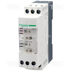
RM4TR32 Реле контроля 3-фазной сети: Un 380V AC / Uрег. (min…мах) 300…480V AC, без нейтрали; контроль: повышенного/пониженного напряжения, обрыва, чередования фаз; рег. срабатывания 0.1…10сек.; контакты: 2CO; корпус: модульный на DIN-рейку
Данный продукт снят с производства.
Доступна замена для заказа: RM22TR33
Цена розничная
11473.00 ₽
Внимание! Актуальные цены будут указаны в выставленном счете или КП.
Условия доставки
Доставка заказа от 250 рублей*
*Весом до 1 кг, до пункта выдачи курьерской службы в г. Москва
- Доставка по всей России до двери или в пункт выдачи
- Ежедневная отправка заказов курьерскими службами
- Бесплатная доставка до терминалов ТК два раза в неделю
- Самовывоза нет
- Документы

Похожие товары
Артикул
Наименование
Наличие
Ед. изм.
Цена розн.
RM22TR33 SCHNEIDER ELECTRIC
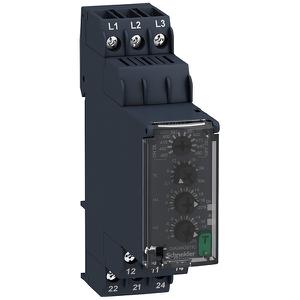
Доставляем ушедшие из РФ бренды напрямую из США и Европы. Есть вопросы? Напишите нам в WhatsApp!
×
Сейчас вы находитесь в городе Москва
Выберите город, в который Вы хотите осуществить доставку
В чем наша ценность
Покупки без ограничений
- Доставка в любой город СНГ
- Простой процесс оплаты
- Каталог на русском языке
Доступ к 3 млн. товаров
- Доставка в любой город СНГ
- Простой процесс оплаты
- Каталог на русском языке
Консолидация и сервис
- Доставка в любой город СНГ
- Простой процесс оплаты
- Каталог на русском языке
Покупки в США и Европе — это просто
Вы делаете заказ — мы выкупаем товары и доставляем вам
Склад

$46
Косметика M.A.C.maccosmetics.com

$46
Часы Timexamazon.com

$15
Джинсы levi’sebay.com
К вам домойОтправляем в Россию и
во все страны СНГ
Начать выгодные покупки в зарубежных интернет-магазинах
Реле контроля фаз, пределы от 380 до 500 Вольт
Реле контроля фаз RM4TR32 от компании Schneider Electric предназначено для контроля следующих параметров электрических сетей:
• превышение (снижение) напряжения выше (ниже) фиксированного значения;
• контроль порядка чередования фаз;
• обрыв фаз.
Применяется в различных схемах автоматики, где требуется контроль вышеуказанных электрических параметров.
RM4TR32 применяется для защиты промышленного оборудования от выгорания не первое десятилетие.
Что защищает реле контроля фаз? Главным образом, трехфазная сеть необходима для трехфазных асинхронных двигателей и мощных источников питания. С источниками питания все просто, чем равномернее нагружаются три фазы, тем стабильнее они работают. У двигателей немного сложнее. Подключение реле контроля фаз RM4TR32: Три фазы подключаются параллельно сети, к контактным группам реле RM4TR32 — L1 / L2 / L3. Фазы важно подключить в той же последовательности, как маркировка у реле. Для аварийного отключения электро двигателя, мы включаем катушку контактора / магнитного пускателя через релейный выход. Если катушка пускателя 220 Вольт, подключение такое: ноль мы присоединяем к контакту А1, к контакту А2 подсоединяем «фазу» пропустив через 15 и 18 контакты RM4TR32. Три фазы на двигатель включаем на контакты L1, L2, L3 и T1,T2, T3 контактора. Подав на RM4TR32 три фазы, реле некоторое время оценивает параметры с установленными значениями и при их совпадении включает контактор, который в свою очередь подает питание на двигатель. Параметры задаваемые на RM4TR32: >U 420-580 Вольт — верхний предел по напряжению, чаще всего выставляется 420, потенциометр 1 — >U >U 420-300 Вольт — нижний предел по напряжению, чаще всего выставляется 340, потенциометр 2 ->U Function — конверт, в одном случае это автоматическое включение после окончания аварии, в другом включение реле после отключения всех трех фаз. Чаще других выставляется конверт — режим АВТО — конверт, потенциометр 3 — Function Delay-t — время срабатывания при появлении аварии. 0.1 сек выставляется в большинстве случаев, 1-10 сек выставляется при так называемом «тяжелом пуске» мотора, потенциометр 4 — Delay t Пять светодиодных индикаторов подскажут Вам состояние реле 1. >U — Красный — авария по напряжению скачок 2. < U — Красный — авария по напряжению падение 3. P — Красный — перекос, выпадение фаз 4. R — Желтый — индикатор срабатывания реле 5. U — Зеленый — питание подано, все в порядке