-
Contents
-
Table of Contents
-
Bookmarks
Quick Links
Related Manuals for Rocktron UTOPIA G100
Summary of Contents for Rocktron UTOPIA G100
-
Page 2
Your UTOPIA G100 has been designed to comply with the following Standards and Direc- tives as set forth by the European Union: Council Directive(s): 89/336/EEC, 73/23/EEC, 76/769/EC, 1994/62/EC, 2000/ 53/EC, 2002/95/EC Standard(s): EN55022, EN50082-1, EN60065 This means that this product has been designed to meet stringent guidelines on how much RF energy it can emit, and that it should be immune from other sources of interference when properly used. -
Page 3: Table Of Contents
Contents 1. Introduction ………………..4 2. Quick Reference ……………….. 6 3. UTOPIA G100 Top and Back Panels …………8 4. Connections………………..11 5. Operating Format ………………17 GLOBAL Function ………………………………… 19 MIXER Function ………………………………….20 PREAMP Function ………………………………… 21 HUSH® Function ………………………………….22 SPEAKER SIMULATOR Function …………………………….
-
Page 4: Introduction
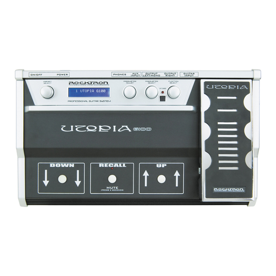
Bank UP, Bank DOWN, and RECALL footswitches For a thorough explanation of the Utopia G100 and its features, please read this manual carefully and keep it for future reference. After removing the Utopia G100 from the box, save all packing materials in case it becomes necessary to ship the unit.
-
Page 5
PRECAUTIONS NOTE: IT IS VERY IMPORTANT THAT YOU READ THIS SECTION TO PROVIDE YEARS OF TROUBLE FREE USE. THIS UNIT REQUIRES CAREFUL HANDLING. • All warnings on this equipment and in the operating instructions should be adhered to and all operating instructions should be followed. •… -
Page 6: Quick Reference
2. Quick Reference…
-
Page 7
Recall the preset you have scrolled to by pressing the RECALL button. NOTE, holding the RECALL button down for two seconds will MUTE the output of the UTOPIA G100. To disengage the MUTE, hold the RECALL button down for two seconds. -
Page 8: Utopia G100 Top And Back Panels
3. UTOPIA G100 Top and Back Panels…
-
Page 9
In the «Title Edit» function, this knob will scroll through the character locations to be edited. 6 FUNCTION SELECT control This knob allows access to each function of the UTOPIA G100 depending on which con- figuration is currently recalled. 7 EXPRESSION PEDAL The built-in expression pedal will change parameter(s) that have been assigned to the pedal in the Pedal Controllers function. -
Page 10
PA system, two guitar amplifiers, etc. 13 OUTPUT LEFT/MONO jack This 1/4″ jack provides the left output of the UTOPIA G100. This output is a MONO output and should be used in mono situations, such as plugging into the front of an amplifier. For stereo situations you must also use the OUTPUT RIGHT Jack. -
Page 11: Connections
4. Connections Standard Connection with a Guitar Amplifier…
-
Page 12
4. Connections..continued..Connection to a Stereo Power Amplifier… -
Page 13
4. Connections..continued..Connection in Stereo to Two Guitar Amplifiers. -
Page 14
4. Connections..continued..Connection to a PA System… -
Page 15
4. Connections..continued..Connection to a Computer… -
Page 16
4. Connections..continued..Connection to a Recording Workstation… -
Page 17: Operating Format
The root of each preset’s sound is its configuration. The configuration determines both the effects available for a given preset and the order in which those effects are executed. The Utopia G100 provides 6 fixed con- figurations to achieve a wide array of preset sounds, any of which may be instantly called up at any time.
-
Page 18
The UTOPIA G100 is set up to allow you to first access each function (via the FUNCTION SELECT knob), then the parameter list for each function (via the PARAMETER SELECT knob) and finally the adjustable value for each parameter (via the PARAMETER ADJUST knob). -
Page 19: Global Function
GLOBAL Function The first function displayed after turning the FUNCTION SELECT knob is the Global function. The parameters provided in this function affect all presets (i.e. the settings stored for these parameters are the same for all presets). The PARAMETER SELECT knob will allow you to access these Global parameters: OUTPUT The OUTPUT parameter determines whether the output of the UTOPIA G100 is a stereo (left and right) signal or two mono signals.
-
Page 20: Mixer Function
MIXER Function The next function displayed after turning the FUNCTION SELECT knob clockwise is the Mixer function. The Mixer function parameters are included in all presets — regardless of which configu- ration is currently recalled — although the parameter values stored in this function are only for the currently recalled preset.
-
Page 21: Preamp Function
The VARIAC ADJUST parameter adjusts the level at which the preamp stage in the UTOPIA G100 begins to distort. A Variac is a voltage attenuat- ing device that plugs into an AC wall outlet and adjusts the voltage level to any device which is plugged into it.
-
Page 22: Hush® Function
HUSH is a patented single-ended noise reduction system. The HUSH system contained in the UTOPIA G100, though modeled after the latest analog HUSH design, is a fully digital imple- mentation achieved through Digital Signal Processing (DSP). The low level expander of the HUSH system operates like an electronic volume control. The analog version of the HUSH utilizes a voltage-controlled amplifier (VCA) circuit which can control the gain between the input and the output from unity to 30, 40 or even 50(dB) of gain reduction.
-
Page 23: Speaker Simulator Function
SPEAKER SIMULATOR Function The SPEAKER SIMULATOR function is included in all presets and provides a realistic ap- proximation of a miked speaker cabinet for applications involving connecting the UTOPIA G100 directly to a mixing board, recording system or other full range system.
-
Page 24: Compressor Function
COMPRESSOR Function The COMPRESSOR function is available in all configurations. This function allows you to compress the signal prior to the distortion stage. Compression is often used to maintain an even level when using clean tones, and also to increase sustain when using distorted tones. The PARAMETER SELECT knob will allow you to access these COMPRESSOR parameters: COMPRESSOR The COMPRESSOR IN/OUT parameter determines whether the…
-
Page 25: Wah-Wah Function
The WAH-WAH function is available only in configurations which display «WAH» in the configu- ration title. The UTOPIA G100 has an internal wah-wah which allows for the built-in expression pedal to be used as a wah-wah pedal when selected in the Pedal Controllers function. To do this, you will need to activate this in the «PEDAL CONTROLLERs»…
-
Page 26: Phaser Function
PHASER Function The PHASER function is available only in configurations displaying «PHA» in the configuration title. Phase shifting involves splitting the input signal into two signals, then shifting the phase of different frequencies of one signal and mixing it back with the original signal. The PARAMETER SELECT knob will allow you to access these PHASER parameters: PHASER The PHASER IN/OUT parameter determines whether the Phaser is active…
-
Page 27: Flanger Function
FLANGER Function The FLANGER function is available only in configurations displaying «FLA» in the configuration title. Flanging involves splitting the input signal into at least two individual delayed signals (Voice 1 and voice 2), then modulating these delayed signals so that, when summed back with the direct signal, phase cancellations will occur at some frequencies while peaks in the response will occur at others.
-
Page 28: Tremolo Function
TREMOLO Function The TREMOLO function is available only in configurations displaying «TRE» in the configuration title. The Tremolo effect continuously varies the volume of the signal. The PARAMETER SELECT knob will allow you to access these TREMOLO parameters: TREMOLO I/O The TREMOLO IN/OUT parameter determines whether the Tremolo is active or bypassed for the current preset.
-
Page 29: Pitch Shift Function
The PAN parameter allows you to pan the shifted signal to the left or right channel. PITCH The PITCH parameter selects what harmony note the UTOPIA G100 will produce based on the input note. The value displayed for this parameter represents the number of cents that the signal will be shifted (adjustable in 20-cent increments).
-
Page 30: Pitch Shift Intervals
PITCH SHIFT INTERVALS CORRESPONDING PARAMETER INTERVAL VALUE +1200 1 Octave Major 7th +1100 minor 7th +1000 Major 6th +900 Voices above the input signal +800 minor 6th perfect 5th +700 diminished 5th +600 perfect 4th +500 Major 3rd +400 +300 minor 3rd Major 2nd +200…
-
Page 31: Chorus Function
The CHORUS function is available only in configurations displaying «CHR» in the configuration title. The Chorus effect in the UTOPIA G100 is produced by using two delayed signals (Voice 1 and Voice 2), detuning these delayed signals (slightly changing their pitch), then modulating the detune effect so that the amount of pitch detune is constantly varying.
-
Page 32
PAN 2 PAN 2 parameter allows you to pan Voice 2 to the left or right channel. DEPTH 2 The DEPTH 2 parameter adjusts the amount of modulation of the Voice 2 signal. A lower depth setting will produce a more subtle detune effect, while a higher setting will produce a more extreme detuning of Voice 2. -
Page 33: Delay Function
Delay is a reproduction of the input signal, occurring at a prescribed time (usually expressed in milliseconds) following the input signal. The UTOPIA G100 provides two discrete delays (Delay 1 and Delay 2), each of which has its own parameters to determine its particular characteristics.
-
Page 34
SOURCE 2 The SOURCE 2 parameter is used to select whether the Source 2 input will be the VOICE 2 output from the previous effect in the signal chain or the direct signal (DIR). DLY HF DAMP The DELAY HIGH FREQUENCY DAMPING parameter controls the amount of high frequency content in the delayed and regenerated signals. -
Page 35: Reverb Function
REVERB Function The REVERB function is available in all presets. Reverb is a multitude of echoes spaced so close together that, to the human ears seem as a single continuous sound. These echoes gradually decrease in intensity until they are ulti- mately absorbed by the boundaries and obstacles within a room.
-
Page 36: Utopia G100 Configurations
6. UTOPIA G100 Configurations PRE, CHR, DL, REV Configuration (Preamp, Chorus, Delay, Reverb)
-
Page 37
PRE, CHR, DL, REV Parameter List — — Preamp, Chorus, Delay, Reverb FUNCTION (via FUNCTION SELECT) (via PARAMETER SELECT) (via PARAMETER ADJUST) GLOBAL OUTPUT (Output Level) Stereo, Mono SPKR SIM (Speaker Simulator Lock) Unlock, Lock Off, Lock L, Lock B +30(dB) MASTER VOLUME -40(dB) to +6(dB) -
Page 38
PRE, CHR, DL, REV Parameter List — — continued..FUNCTION PARAMETER LIST RANGE (via FUNCTION SELECT) (via PARAMETER SELECT) (via PARAMETER ADJUST) DELAY DELAY (Delay Status v i t MIX (Source 1/Source 2 Mix Level) S1 <0 to 100> S2 SOURCE 2 (Source 2 Select) DIRECT, Voice 2 DLY HF DAMP (Delay High Frequency Damping) -
Page 39: Pre, Fla, Dl, Rev Configuration
PRE, FLA, DL, REV Configuration Preamp, Flanger, Delay, Reverb…
-
Page 40
PRE, FLA, DL, REV Parameter List — — Preamp, Flanger, Delay, Reverb FUNCTION (via FUNCTION SELECT) (via PARAMETER SELECT) (via PARAMETER ADJUST) GLOBAL OUTPUT (Output Level) Stereo, Mono SPKR SIM (Speaker Simulator Lock) Unlock, Lock Off, Lock L, Lock B +30(dB) MASTER VOLUME -40(dB) to +6(dB) -
Page 41
PRE, FLA, DL, REV Parameter List — — continued..FUNCTION (via FUNCTION SELECT) (via PARAMETER SELECT) (via PARAMETER ADJUST) DELAY DELAY (Delay St v i t MIX (Source 1/Source 2 Mix Level) S1 <0 to 100> S2 SOURCE 2 (Source 2 Select) DIRECT, Voice 2 DLY HF DAMP (Delay High Frequency Damping) 0 to 99… -
Page 42: Pre, Tre, Dl, Rev Configuration
PRE, TRE, DL, REV Configuration Preamp, Tremolo, Delay, Reverb…
-
Page 43
PRE, TRE, DL, REV Parameter List — — Preamp, Tremolo, Delay, Reverb FUNCTION (via FUNCTION SELECT) (via PARAMETER SELECT) (via PARAMETER ADJUST) GLOBAL OUTPUT (Output Level) Stereo, Mono SPKR SIM (Speaker Simulator Lock) Unlock, Lock Off, Lock L, Lock B +30(dB) MASTER VOLUME -40(dB) to +6(dB) -
Page 44
PRE, TRE, DL, REV Parameter List — — continued..FUNCTION (via FUNCTION SELECT) (via PARAMETER SELECT) (via PARAMETER ADJUST) DELAY DELAY (Delay St v i t MIX (Source 1/Source 2 Mix Level) S1 <0 to 100> S2 SOURCE 2 (Source 2 Select) DIRECT, Voice 2 DLY HF DAMP (Delay High Frequency Damping) 0 to 99… -
Page 45: Pre, Psh, Dl, Rev Configuration
PRE, PSH, DL, REV Configuration Preamp, Pitch Shift, Delay, Reverb…
-
Page 46
PRE, PSH, DL, REV Parameter List — — Preamp, Pitch Shift, Delay, Reverb FUNCTION (via FUNCTION SELECT) (via PARAMETER SELECT) (via PARAMETER ADJUST) GLOBAL OUTPUT (Output Level) Stereo, Mono SPKR SIM (Speaker Simulator Lock) Unlock, Lock Off, Lock L, Lock B +30(dB) MASTER VOLUME -40(dB) to +6(dB) -
Page 47
PRE, PSH, DL, REV Parameter List — -continued..FUNCTION (via FUNCTION SELECT) (via PARAMETER SELECT) (via PARAMETER ADJUST) DELAY DELAY (Delay St v i t MIX (Source 1/Source 2 Mix Level) S1 <0 to 100> S2 SOURCE 2 (Source 2 Select) DIRECT, Voice 2 DLY HF DAMP (Delay High Frequency Damping) 0 to 99… -
Page 48: Wa, Pre, Dl, Rev Configuration
WA, PRE, DL, REV Configuration Wah Wah, Preamp, Delay, Reverb…
-
Page 49
WA, PRE, DL, REV Parameter List — — Wah-Wah, Preamp, Delay, Reverb FUNCTION (via FUNCTION SELECT) (via PARAMETER SELECT) (via PARAMETER ADJUST) GLOBAL OUTPUT (Output Level) Stereo, Mono SPKR SIM (Speaker Simulator Lock) Unlock, Lock Off, Lock L, Lock B +30(dB) MASTER VOLUME -40(dB) to +6(dB) -
Page 50
WA, PRE, DL, REV Parameter List — — continued..FUNCTION (via FUNCTION SELECT) (via PARAMETER SELECT) (via PARAMETER ADJUST) DELAY DELAY (Delay St v i t MIX (Source 1/Source 2 Mix Level) S1 <0 to 100> S2 SOURCE 2 (Source 2 Select) DIRECT, Voice 2 DLY HF DAMP (Delay High Frequency Damping) 0 to 99… -
Page 51: Pha, Pre, Dl, Rev Configuration
PHA, PRE, DL, REV Configuration Phaser, Preamp, Delay, Reverb…
-
Page 52
PHA, PRE, DL, REV Parameter List — — Phaser, Preamp, Delay, Reverb FUNCTION (via FUNCTION SELECT) (via PARAMETER SELECT) (via PARAMETER ADJUST) GLOBAL OUTPUT (Output Level) Stereo, Mono SPKR SIM (Speaker Simulator Lock) Unlock, Lock Off, Lock L, Lock B +30(dB) MASTER VOLUME -40(dB) to +6(dB) -
Page 53
PHA, PRE, DL, REV Parameter List — — continued..FUNCTION (via FUNCTION SELECT) (via PARAMETER SELECT) (via PARAMETER ADJUST) DELAY DELAY (Delay St v i t MIX (Source 1/Source 2 Mix Level) S1 <0 to 100> S2 SOURCE 2 (Source 2 Select) DIRECT, Voice 2 DLY HF DAMP (Delay High Frequency Damping) 0 to 99… -
Page 54: Operating The Utopia G100
Selecting a preset: Step 1 There are two ways to select a preset on the UTOPIA G100. You can either turn the PRESET knob to the desired preset you wish to recall. The display will show the selected preset number. Using this knob to select a preset provides automatic recall.
-
Page 55: Changing Preset Parameters
Changing preset parameters: Turn the FUNCTION SELECT knob to select the function heading which contains Step 1 the parameter(s) you wish to change. **** REVERB **** Step 2 Turn the PARAMETER SELECT knob to the specific parameter you wish to change.
-
Page 56: Storing Changed Preset Parameters
Storing changed preset parameters: While viewing a function or parameter title, press the STORE button to start the Step 1 store procedure. The display will now alternate between the destination preset number and title and «STORE AT PRESET» 29 PRESET TITLE STORE AT PRESET Turn the PRESET knob to select the desired preset number to store the new Step 2…
-
Page 57: Selecting A Configuration
WA,PRE,DL,REV Note: The new configuration will not take effect until it is stored. Step 4 Press the STORE button to initiate the store procedure. The UTOPIA G100 display will alternate between the current preset number/title and «STORE AT PRESET». 29 PRESET TITLE…
-
Page 58: Editing A Preset Title
NOTE: The STORE button must be pressed to save the new title. Exiting the Title Edit function before pressing the STORE button will erase any editing that was done in Title Edit. Also, after flashing «STORED», the UTOPIA G100 will exit the title edit mode and return to the main preset number.
-
Page 59: Pedal Controllers
Pedal Controllers The «Pedal Controllers» function allows for specific UTOPIA G100 adjustable parameters to be mapped (or assigned) to the built-in expression pedal for real-time control over the selected parameter. The Pedal Controllers option lets you assign one controller for «quick adjust» or assign one or two parameters to the built-in expression pedal.
-
Page 60
ULIM C1 NOTE: The UTOPIA G100 allows you to select an upper and lower value limit which the parameter cannot exceed. For example, if a parameter has a value range from 0 to 127, yet you would like the range of the parameter to vary from only 50 to 127, you may set a lower limit of 50 and an upper limit of 127 via the Upper (ULIM) and Lower Limit (LLIM) parameters. -
Page 61
Pedal Controllers..continued….. You now must store your changes. If you have made any changes to any param- Step 12 eter, the LED above the «STORE» button will light. Press the STORE button to save the changes you have made. «STORE AT PRESET» will flash intermittently with the current preset. -
Page 62: Pedal Status
The PEDAL STATUS is for use with the built-in expression pedal. By setting the RUN STAT parameter to ON, the UTOPIA G100 will track the position of the expression pedal (assuming the expressoin pedal is presently or had been previously assigned to «PEDAL VOLU») and vary the preset volume accordingly from preset to preset.
-
Page 63
Pedal Status..continued….. Step 2 Turn the PARAMETER SELECT knob one step clockwise to the RUN STAT parameter. RUN STAT Step 3 Turn the PARAMETER ADJUST knob to select ON for the RUN STAT param- eter. RUN STAT Step 4 Turn the PARAMETER SELECT knob one step clockwise to the PEDAL VOL- UME parameter. -
Page 64: Factory Restore
The Factory Restore function allows you to restore presets 1-64 that you may have altered to their original condition as shipped from the factory. Either the entire UTOPIA G100 memory can be restored or a single preset can be restored. Note that you do NOT need to restore presets 65 to 128 as these are factory preset that can not be altered and stored.
-
Page 65
Step 2 Turn the PARAMETER SELECT knob 2 steps clockwise to «ALL RESTORE 0». ALL RESTORE A specific code number must be entered to restore the UTOPIA G100 memory Step 3 Use the PARAMETER ADJUST knob to enter the number «22». -
Page 66: Selecting A Power On Preset
Selecting a Power on Preset: The UTOPIA G100 allows you to store a Power On preset which will always be recalled when the unit is turned on. Turn the PRESET knob to the preset number you wish to be recalled each time Step 1 the unit is turned on.
-
Page 67: Specifications
Specifications Input Impedance 1M Ohm Maximum Input Level +4 dBu @ 1KHz ¼» Input Jack mono + 8 dBu Maximum Output Level ¼» Output Jacks Left and Right. Headphone Jack 1/8″ Stereo (Load Impedance 32 Ohm Min) Important: Listening to headphones at levels above 85 dBu may cause hearing damage! Due to hi output capabilities present in the HEADPHONE OUTPUTS it is…
-
Page 68: Utopia G100 Preset Listing — User Presets
Utopia G100 Preset Listing — user presets Preset Name What it does Pedal Heel Utopia G100 British Distortion w/Delay Volume Zero Volume Full Volume Clean Strat Zero Volume Full Volume Whammy Man British Distortion w/Delay Pitch Actual Pitch Octave Higher…
-
Page 69: Utopia G100 Preset Listing — Factory Presets
Utopia G100 Preset Listing — factory presets Preset Name What it does Pedal Heel Utopia G100 British Distortion w/Delay Volume Zero Volume Full Volume Clean Strat olume Zero Volume Full Volume Whammy Man British Distortion w/Delay Pitch Actual Pitch Octave Higher…
-
Page 72
Rocktron -A Division of GHS Corporation 2813 Wilber Avenue Battle Creek MI 49015 Rocktron Phone: 1-(269)-968-3351 Email: info@rocktron.com Check us out on the web at: www.rocktron.com 2006-0001 Rev. 9/01/06…
Table of Contents for Rocktron UTOPIA G100:
-
3 Contents 1. Introduction ……………………………………………………………………………………… 4 2. Quick Reference ……………………………………………………………………………….. 6 3. UTOPIA G100 Top and Back Panels ………………………………………………….. 8 4. Connections……………………………..
-
26 PHASER Function The PHASER function is available only in configurations displaying «PHA» in the configuration title. Phase shifting involves splitting the input signal into two signals, then shifting the phase of different frequencies of one signal and mixing it back with the original signal. The PARAMETER SELECT knob will allow you to access these PHASER parameters: The PHASER IN/OUT parameter determines whether the Phaser is active for the cu
-
22 The HUSH ® function is accessible in all presets — regardless of the configuration currently recalled. HUSH is a patented single-ended noise reduction system. The HUSH system contained in the UTOPIA G100, though modeled after the latest analog HUSH design, is a fully digital imple- mentation achieved through Digital Signal Processing (DSP). The low level expander of the HUSH system operates like an electronic volume control. The analog version of the HUSH utilizes a voltage-controlled amplifier (VCA) circuit which can control the gain between
-
39 PRE, FLA, DL, REV Configuration Preamp, Flanger, Delay, Reverb
-
35 REVERB Function The REVERB function is available in all presets. Reverb is a multitude of echoes spaced so close together that, to the human ears seem as a single continuous sound. These echoes gradually decrease in intensity until they are ulti- mately absorbed by the boundaries and obstacles within a room. As the sound waves from the sound source strike the boundaries of a room, a portion of the energy is reflected away from the obst
-
6 2. Quick Reference
-
24 COMPRESSOR Function The COMPRESSOR IN/OUT parameter determines whether the compressor is active for the current preset. The COMPRESSOR THRESHOLD parameter determines the input level (in dB) at which compression will begin. Lower settings of this parameter will result in more compression. The COMPRESSOR ATTACK parameter determines the speed (in milliseconds) in which the compressor will reach its maximum compression level after the inp
-
12 Connection to a Stereo Power Amplifier 4. Connections….continued…..
-
28 TREMOLO Function The TREMOLO function is available only in configurations displaying «TRE» in the configuration title. The Tremolo effect continuously varies the volume of the signal. The PARAMETER SELECT knob will allow you to access these TREMOLO parameters: The TREMOLO IN/OUT parameter determines whether the Tremolo is active or bypassed for the current preset. The LOCATION parameter determines whether the Tremolo is located Pre-Reverb or Post-Reverb. Most v
-
55 Step 1 3 1 2 **** REVERB **** REV DECAY 32 Step 3 Step 2 REV DECAY 59 NOTE: If you have changed a parameter the «STORE» LED will light. The change(s) that you made will not be stored until you have pressed the «STORE» button. Please follow instructions on the next page for details on how to store changed parameters. Changing preset parameters: Turn the FUNCTION SELECT knob to select the function heading which contains the parameter(s) you wish to change. Turn the PARAMETER SELECT k
-
18 UTOPIA G100 Functions and Parameter Descriptions Each UTOPIA G100 preset is divided up into individual blocks called functions (such as «Mixer», «Reverb», etc.). Within each function of each configuration is a set of controls which allow you to manipulate various as- pects of that function. These controls are called parameters. It is the setting of each of the parameters which determines the overall sound of each pre- set. The UTOPIA G100 is set up to allow you to first access each function (via the FUNCTION SELECT knob), then the parame
-
70
-
50 FUNCTION P EGNARTSIL RETEMARA (via FUNCTION SELECT) (via PARAMETER SELECT) (via PARAMETER ADJUST) DELAY DELAY (Delay St evitcA ,detuM)suta htoB ,tsoP ,erP)sutatS epyT etuM( EPYT ETUM )Bd(4+ ot FFO)leveL yaleD( LVL YALED MIX (Source 1/Source 2 Mix Level) S1 <0 to 100> S2 SOURCE 2 (Source 2 Select) DIRECT, Voice 2 DLY HF DAMP (Delay High Frequency Damping) 0 to 99 )Bd(4+ ot FFO)leveL 1 yaleD( 1 LEVEL TUO R >001 ot 0< L)gninnaP 1
-
42 PRE, TRE, DL, REV Configuration Preamp, Tremolo, Delay, Reverb
Questions, Opinions and Exploitation Impressions:
You can ask a question, express your opinion or share our experience of Rocktron UTOPIA G100 device using right now.

1
Your UTOPIA G100 has been designed to comply with the following Standards and Directives as set forth by the European Union:
Council Directive(s):
89/336/EEC, 73/23/EEC, 76/769/EC, 1994/62/EC, 2000/
53/EC, 2002/95/EC
Standard(s):
EN55022, EN50082-1, EN60065
This means that this product has been designed to meet stringent guidelines on how much
RF energy it can emit, and that it should be immune from other sources of interference
when properly used. Improper use of this equipment could result in increased RF emissions, which may or may not interfere with other electronic products.
To insure against this possibility, always use good shielded cables for all audio input and
output connections. This will help insure compliance with the Directive(s).
Copyright © 2006 GHS Corporation.
All rights reserved.
2
Contents
1.
2.
3.
4.
5.
Introduction ................................................................................................... 4
Quick Reference ............................................................................................ 6
UTOPIA G100 Top and Back Panels ........................................................... 8
Connections................................................................................................. 11
Operating Format ........................................................................................ 17
GLOBAL Function ............................................................................................................................................................................................... 19
MIXER Function ................................................................................................................................................................................................... 20
PREAMP Function ............................................................................................................................................................................................... 21
HUSH® Function .................................................................................................................................................................................................. 22
SPEAKER SIMULATOR Function ....................................................................................................................................................................... 23
COMPRESSOR Function .................................................................................................................................................................................... 24
WAH-WAH Function ............................................................................................................................................................................................ 25
PHASER Function ................................................................................................................................................................................................ 26
FLANGER Function ............................................................................................................................................................................................. 27
TREMOLO Function ............................................................................................................................................................................................ 28
PITCH SHIFT Function ........................................................................................................................................................................................ 29
PITCH SHIFT INTERVALS .................................................................................................................................................................................... 30
CHORUS Function ............................................................................................................................................................................................... 31
DELAY Function .................................................................................................................................................................................................. 33
REVERB Function ................................................................................................................................................................................................ 35
6. UTOPIA G100 Configurations .................................................................... 36
PRE, CHR, DL, REV Configuration .................................................................................................................................................................... 36
PRE, FLA, DL, REV Configuration .................................................................................................................................................................... 39
PRE, TRE, DL, REV Configuration ..................................................................................................................................................................... 42
PRE, PSH, DL, REV Configuration .................................................................................................................................................................... 45
WA, PRE, DL, REV Configuration ...................................................................................................................................................................... 48
PHA, PRE, DL, REV Configuration .................................................................................................................................................................... 51
7. Operating the UTOPIA G100 ...................................................................... 54
Selecting a preset: ............................................................................................................................................................................................ 54
Changing preset parameters: ....................................................................................................................................................................... 55
Storing changed preset parameters: ........................................................................................................................................................... 56
Selecting a configuration: ................................................................................................................................................................................ 57
Editing a preset title: ......................................................................................................................................................................................... 58
Pedal Controllers .............................................................................................................................................................................................. 59
Pedal Status ........................................................................................................................................................................................................ 62
Factory Restore ................................................................................................................................................................................................. 64
Selecting a Power on Preset: ......................................................................................................................................................................... 66
Specifications ..................................................................................................................................................................................................... 67
UTOPIA G100 Preset Listing - User Presets ................................................................................................................................................ 68
UTOPIA G100 Preset Listing - Factory Presets ........................................................................................................................................... 69
3
1. Introduction
Rocktron’s Utopia G100 Professional Guitar System provides guitar tone and effects processing for the next
generation so you can be the player you want to be. You will not find your Pop’s old guitar amps and cabinets
modeled in Utopia! What you will find is a compact powerhouse of great sounds ready to rock. Rocktron
stands alone with amazing distortion and effects in the G100 - everything you need to create your own signature sound and define a new generation of playing. Play in Utopia, not your Daddy’s band!
Easy to use and operate.
Motorola 24 Bit DSP Engine
Four channels of tone (Clean, Texas, British, Mega) with 128 preset sounds (64 factory preset sounds and 64
user presets).
Full bandwidth effects. Pre-effects include wah, phaser, compressor. Post effects include chorus, flanger,
tremolo, delay, reverb.
Rugged professional grade chassis and expression control pedal made from metal.
Rocktron exclusives include state-of-the-art Speaker Simulation (for ultimate recording capabilities), Variac
(tube sag emulation) and HUSH noise reduction.
Easy to read Cool Blue LCD display.
64 Fully Programmable Presets.
Stereo Outputs
Heavy Duty Headphone Output
Auxiliary (MP3/CD/IPOD) Input
Store Button with LED
Bank UP, Bank DOWN, and RECALL footswitches
For a thorough explanation of the Utopia G100 and its features, please read this manual carefully and keep it for
future reference. After removing the Utopia G100 from the box, save all packing materials in case it becomes
necessary to ship the unit.
Motorola is a trademark of Motorola Corporation. HUSH is a registered trademark of GHS Corporation.
4
PRECAUTIONS
NOTE: IT IS VERY IMPORTANT THAT YOU READ THIS SECTION TO PROVIDE
YEARS OF TROUBLE FREE USE. THIS UNIT REQUIRES CAREFUL HANDLING.
• All warnings on this equipment and in the operating instructions should be
adhered to and all operating instructions should be followed.
• Do not use this equipment near water. Care should be taken so that objects do
not fall and liquids are not spilled into the unit through any openings.
• The power cord/adapter should be unplugged from the outlet when left unused
for a long period of time.
• Do not block any ventilation openings (if applicable). Install in accordance with
the manufacturer’s instructions.
• Do not install near any heat sources such as radiators, heat registers, stoves or
other apparatus (including amplifiers) that produce heat.
• Only used attachments/accessories specified by the manufacturer.
• Do not use this product with any case, stand tripod, bracket or table that is not
specified by the manufacturer. Insure that the case, stand, tripod, bracket etc. is
properly adjusted and setup (follow all instructions). Extra care and caution
should be taken to avoid tip over and injury.
• Unplug this apparatus during lightning storms or when unused during long
periods of time.
Refer all service to qualified service personnel. Servicing is required when the apparatus has been damaged
in any way, such as power supply or plug is damaged, liquid has been spilled or objects have fallen into the
apparatus or if the apparatus has been exposed to rain or moisture, does not operate normally or has been
dropped.
DO NOT ATTEMPT TO SERVICE THIS EQUIPMENT. THIS EQUIPMENT
SHOULD BE SERVICED BY QUALIFIED PERSONNEL ONLY. DO NOT MAKE ANY
INTERNAL ADJUSTMENTS OR ADDITIONS TO THIS EQUIPMENT AT ANY TIME.
DO NOT TAMPER WITH INTERNAL ELECTRONIC COMPONENTS AT ANY TIME.
FAILURE TO FOLLOW THESE INSTRUCTIONS MAY VOID THE WARRANTY OF
THIS EQUIPMENT, AS WELL AS CAUSING SHOCK HAZARD.
OPERATING TEMPERATURE
Do not expose this unit to excessive heat. This unit is designed to operate between 32° F
and 104° F (0° C and 40° C). This unit may not function properly under extreme temperatures.
5
2. Quick Reference
6
Quick Reference....continued...
STEP1
Turn ON the UTOPIA G100.
STEP 2
Scroll through the presets by pressing the DOWN button. You may
also do this by following STEP 3.
STEP 3
Scroll through the presets by pressing the UP button. You may also
do this by following STEP 2.
STEP 4
Recall the preset you have scrolled to by pressing the RECALL
button. NOTE, holding the RECALL button down for two seconds
will MUTE the output of the UTOPIA G100. To disengage the MUTE,
hold the RECALL button down for two seconds.
STEP 5
Use the built-in expression pedal to change the parameter(s) in real
time that are assigned to the pedal controller function,
STEP 6
You may also select a preset by turning the PRESET SELECT
knob. Note, that this knob automatically recalls the preset, you do
NOT need to press the recall button.
STEP 7
Turn the FUNCTION SELECT knob to the desired effect or utility
function.
STEP 8
Turn the PARAMETER SELECT knob to the parameter you wish to
alter under the selected effect or utility function
.
STEP 9
Use the PARAMETER ADJUST knob to select the new parameter
value.
STEP 10 Press the STORE button to start the storing procedure. If you wish
to save the altered preset in the current preset location, press the
STORE button a second time. If you wish to store the altered preset
in a different preset location, turn the PRESET control to the desired
preset number, then press STORE a second time.
7
3. UTOPIA G100 Top and Back Panels
8
3.
UTOPIA G100 Top and Back Panels....continued.....
1 PRESET SELECT control
Turning this knob scrolls through the successive presets. The presets are automatically
recalled.
2 DISPLAY panel
The DISPLAY shows the preset names, functions and parameters that are selected.
3 PARAMETER ADJUST control
This knob is used to adjust a displayed parameter value.
5 STORE button and STORE LED
This button is used to store values into the G100's memory when altered. See "Storing
Changed Preset Parameters" for more information on this procedure.
4 PARAMETER SELECT control
When adjusting parameter values, turning this knob will scroll through the available parameters under the current function heading. In the "Title Edit" function, this knob will scroll
through the character locations to be edited.
6 FUNCTION SELECT control
This knob allows access to each function of the UTOPIA G100 depending on which configuration is currently recalled.
7 EXPRESSION PEDAL
The built-in expression pedal will change parameter(s) that have been assigned to the
pedal in the Pedal Controllers function. Use the pedal to increase or decrease volume
levels, or for a pitch shifting whammy effect, or to bring in reverbs and delays. There are
many uses for this pedal. Please see the Pedal Controllers section of this manual for
information how to program the expression pedal for many cool effects.
8 DOWN button
This button allows you to scroll DOWN through the available presets. Press the button
once to move one preset down, or press and hold down the button to auto-scroll DOWN.
Note that once you have reached your desired preset, the preset name on the screen will
be flashing but NOT recalled. The original preset will still be active. To recall or activate the
desired preset you will need to press the "RECALL" button.
9 RECALL/MUTE button
This button allows you RECALL or activate the preset you have scrolled to using the
DOWN or UP button. Pressing and holding down this button for two seconds will MUTE the
output of the UTOPIA G100. To disengage the MUTE function, press the RECALL/MUTE
button again.
9
3.
UTOPIA G100 Top and Back Panels....continued.....
10 UP button
This button allows you to scroll UP through the available presets. Press the button once to
move one preset UP, or press and hold down the button to auto-scroll UP. Note that once
you have reached your desired preset, the preset name on the screen will be flashing but
NOT recalled. The original preset will still be active. To recall or activate the desired
preset you will need to press the "RECALL" button.
11 INPUT jack
This standard, mono 1/4" jack is used to provide input to the unit.
12 OUTPUT RIGHT jack
This 1/4" jack provides the right output of the UTOPIA G100 for use in stereo situations,
such as direct recording, plugging into a PA system, two guitar amplifiers, etc.
13 OUTPUT LEFT/MONO jack
This 1/4" jack provides the left output of the UTOPIA G100. This output is a MONO output
and should be used in mono situations, such as plugging into the front of an amplifier. For
stereo situations you must also use the OUTPUT RIGHT Jack.
14 AUX INPUT Jack
This 1/8" stereo jack provides an Auxiliary input allowing you to plug a MP3 Player, CD
Player, etc. so that you can jam along with your favorite tunes.
15 PHONES jack
This 1/8" stereo jack provides a stereo output allowing you to practice in private. Note that
you need to activate the "STEREO" parameter in the GLOBAL Function in order to have a
stereo sound. Additionally, it is recommended that you set the Speaker Simulator in the
GLOBAL Function to "LOCK BOTH" as well. Note, this setting will be used until you turn
OFF the UTOPIA G100. The SPEAKER SIMULATOR setting used in each preset may be
modified per preset while in this mode. See page 18 for more information on the GLOBAL
Function.
16 POWER jack
This 4-pin DIN connector accepts power from the 9VAC/2A adaptor supplied with the unit.
17 POWER Switch
Use this switch to turn the UTOPIA G100 On and Off.
10
4. Connections
Standard Connection with a Guitar Amplifier
11
4. Connections....continued.....
Connection to a Stereo Power Amplifier
12
4. Connections....continued.....
Connection in Stereo to Two Guitar Amplifiers.
13
4. Connections....continued.....
Connection to a PA System
14
4. Connections....continued.....
Connection to a Computer
15
4. Connections....continued.....
Connection to a Recording Workstation
16
5. Operating Format
The G100 provides 128 stored sounds called presets. The first 64
presets can be changed and saved by the user. The second 64 presets (65128) are not changeable. Any of the 128 presets can be called up at any
time via the PRESET knob, or by using the UP/DOWN/RECALL switches.
The root of each preset's sound is its configuration. The configuration
determines both the effects available for a given preset and the order in
which those effects are executed. The Utopia G100 provides 6 fixed configurations to achieve a wide array of preset sounds, any of which may be
instantly called up at any time.
Utopia G100 Configurations:
PREAMP • CHORUS • DELAY • REVERB
PREAMP • FLANGE • DELAY • REVERB
PREAMP • TREMOLO • DELAY • REVERB
PREAMP • PITCH SHIFT • DELAY • REVERB
WAH • PREAMP • DELAY • REVERB
PHASER • PREAMP • DELAY • REVERB
(PRE CHR DL REV)
(PRE FLA DL REV)
(PRE TRE DL REV)
(PRE PSH DL REV)
(WA PRE DL REV)
(PHA PRE DL REV)
The configuration of each preset can be changed from within the desired
preset. For more information on selecting a configuration, see Selecting a
Configuration in the section titled "Operating the Utopia G100".
17
UTOPIA G100 Functions and Parameter Descriptions
Each UTOPIA G100 preset is divided up into individual blocks called
functions (such as "Mixer", "Reverb", etc.). Within each function of each
configuration is a set of controls which allow you to manipulate various aspects of that function. These controls are called parameters. It is the setting
of each of the parameters which determines the overall sound of each preset.
The UTOPIA G100 is set up to allow you to first access each function (via
the FUNCTION SELECT knob), then the parameter list for each function (via
the PARAMETER SELECT knob) and finally the adjustable value for each
parameter (via the PARAMETER ADJUST knob).
The functions available for each preset are dependent upon which
configuration is currently recalled. The remainder of this section will describe
each of the effect-based functions and the associated adjustable parameters
they provide.
The remaining functions are utility-based, and are described in the section titled "Operating the UTOPIA G100".
18
GLOBAL Function
The first function displayed after turning the FUNCTION SELECT knob is the Global
function. The parameters provided in this function affect all presets (i.e. the settings stored for
these parameters are the same for all presets).
The PARAMETER SELECT knob will allow you to access these Global parameters:
OUTPUT
SPKR SIM
The OUTPUT parameter determines whether the output of the UTOPIA
G100 is a stereo (left and right) signal or two mono signals.
This SPEAKER SIMULATOR parameter under the Global function allows
you to globally (all presets) set the Speaker Simulator into the following
modes:
UNLOCK - Bypasses all Speaker Simulation on all presets leaving the
outputs full range.
LOCKOFF - If you have the Speaker Simulator "ON" in the Speaker Simulator Function the Speaker Simulator will turn on when that preset is selected.
LOCK L (LEFT OUTPUT) - Locks the Speaker Simulator "ON" in the LEFT
OUTPUT and leaves the Right OUTPUT full range. Allows you to use the left
output for direct recording or direct to a PA and the right output to your amp
at the same time to perform live.
LOCK B (BOTH OUTPUTS) - Locks the Speaker Simulator "ON" in both
Left and Right Outputs. This is the ideal setting to use when using headphones.
HUSH OFFSET
The HUSH OFFSET parameter allows you to globally (all presets) adjust the
HUSH® Expander Threshold. This means that if this parameter is altered
from 0(dB) to +3(dB), the Expander Threshold will be 3dB higher for all
presets. This feature can be useful when switching from a quiet guitar with
passive electronics to a noisy guitar with active electronics, as the active
guitar would require a higher Threshold level in all presets.
MASTER VOLUME The MASTER VOLUME parameter allows you to globally (all presets)
adjust the output level of the G100. It provides up to +6dBu more gain
and up to -40dBu of attenuation.
This is most helpful when using headphones to adjust the output level
to a comfortable level quickly. When patching the G100 outputs directly
into a power amp the extra +6dBu of gain can be used for more input
drive.
NOTE: If you would like to save any changes made to the GLOBAL PARAMETERS you must
STORE them at this time, before leaving the GLOBAL FUNCTION.
19
MIXER Function
The next function displayed after turning the FUNCTION SELECT knob clockwise is the Mixer
function. The Mixer function parameters are included in all presets -- regardless of which configuration is currently recalled -- although the parameter values stored in this function are only for the
currently recalled preset.
This digital mixer allows you to control most signal levels pertaining to each preset's configuration and stores these levels for each preset.
The PARAMETER SELECT knob will allow you to access these Mixer parameters:
VOLUME
LEFT OUT LVL
RIGHT OUT LVL
20
The VOLUME parameter determines the overall signal level of the current
preset.
The LEFT OUT LEVEL parameter allows you alter the level of the left
channel output of the current preset independent of the right channel.
The RIGHT OUT LEVEL parameter allows you alter the level of the right
channel output of the current preset independent of the left channel.
MIX DIR/EFF
The DIR/EFF MIX parameter is used to define the ratio of direct signal
level to effect (Chorus, Flange, Pitch Shift) signal level.
DIR PAN
The DIRECT PAN parameter allows you to pan the direct signal to the
left or right.
DELAY LVL
The DELAY LEVEL parameter determines the overall level of the delayed
signal at the output relative to the direct signal and other effect signals.
This parameter can also be accessed from the Delay function parameter
list.
REVERB LVL
The REVERB LEVEL parameter determines the level of the reverb signal
at the output relative to the direct signal and other effect signals. This
parameter can also be accessed from the Reverb function parameter list.
PREAMP Function
The PREAMP function is accessible in all configurations. The preamp stage offers 4 channel choices ranging from clean to high gain for maximum sustain and distortion.
The PARAMETER SELECT knob will allow you to access these PREAMP parameters:
CHANNEL
The CHANNEL parameter chooses one of the four (4) PREAMP types:
Clean, Texas, British, Mega.
GAIN
The GAIN parameter determines the gain value in the distortion stage.
VARlAC ADJUST The VARIAC ADJUST parameter adjusts the level at which the preamp
stage in the UTOPIA G100 begins to distort. A Variac is a voltage attenuating device that plugs into an AC wall outlet and adjusts the voltage level to
any device which is plugged into it. For years, many guitarists have plugged
their amplifier heads into a Variac and reduced the voltage coming into the
amplifier from the AC wall outlet. This allows the amplifier tubes to reach
saturation at a lower input level and increases the gain produced. The
VARIAC ADJUST parameter operates in a similar manner as a conventional Variac -- where lowering the parameter value lowers the level at which
saturation will take place.
BASS
MID
TREBLE
PRESENCE
The BASS parameter adjusts the amount of low frequency information at the
output of each preset.
The MID parameter adjusts the amount of mid frequency information at the
output of each preset.
The TREBLE parameter adjusts the amount of high frequency information at
the output of each preset.
The PRESENCE parameter also adjusts the amount of high frequency
information at the output of each preset.
BRIGHT
The BRIGHT parameter is displayed only when channel 1 (Clean) is active,
and allows you to add extra brightness to the clean channel when switched
on.
SCOOP
The SCOOP parameter is displayed only when Channel 4 (MEGA) is active, and provides a fixed scoop of the mid frequencies.
MASTER
The MASTER parameter determines the overall signal level coming out of
the preamp section.
21
HUSH® Function
The HUSH® function is accessible in all presets - regardless of the configuration currently
recalled.
HUSH is a patented single-ended noise reduction system. The HUSH system contained in
the UTOPIA G100, though modeled after the latest analog HUSH design, is a fully digital implementation achieved through Digital Signal Processing (DSP).
The low level expander of the HUSH system operates like an electronic volume control. The
analog version of the HUSH utilizes a voltage-controlled amplifier (VCA) circuit which can control
the gain between the input and the output from unity to 30, 40 or even 50(dB) of gain reduction.
When the input signal is above the user preset threshold point, the VCA circuit remains at unity
gain. (This means that the amplitude of the output signal will be equal to that of the input signal.)
As the input signal level drops below the user preset threshold point, downward expansion
begins. At this point the expander acts like an electronic volume control and gradually begins to
decrease the output signal level relative to the input signal level. As the input signal drops further
below the threshold point, downward expansion increases. A drop in the input level by 20(dB)
would cause the output level to drop approximately 40(dB) (i.e., 20(dB) of gain reduction). In
the absence of any input signal, the expander will reduce the gain so that the noise floor becomes inaudible.
The HUSH circuit is located after the A/D converter in the signal chain to reduce any noise
generated from the guitar and the A/D converter. This ensures a quiet input signal to the preamp
section. Because the preamp section of the UTOPIA G100 is digital, it is virtually noise-free (even
for the high-gain channels). Therefore, a quiet input signal to the preamp will result in a quiet output
signal.
The PARAMETER SELECT knob will allow you to access these Hush parameters:
HUSH I/O
HUSH THRESH
22
The HUSH I/O parameter simply determines whether the HUSH® circuit
is active for the current preset.
The HUSH THRESHOLD parameter determines the level at which
downward expansion begins. For example, if the HUSH THRESHOLD
was set at -20(dB) and the input signal dropped below -20(dB),
downward expansion would begin.
SPEAKER SIMULATOR Function
The SPEAKER SIMULATOR function is included in all presets and provides a realistic approximation of a miked speaker cabinet for applications involving connecting the UTOPIA G100
directly to a mixing board, recording system or other full range system.
NOTE: The parameters provided in this function are operational
only when the SPKR SIM parameter under the GLOBAL
FUNCTION is stored UNLOCK, LOCK L or LOCK B.
The PARAMETER SELECT knob will allow you to access these SPEAKER SIMULATOR
parameters:
SPKR SIM
SPKR TYPE
The SPEAKER SIMULATOR parameter allows you to select whether the
Speaker Simulator is on for BOTH outputs, on for only the LEFT output or
OFF.
The SPEAKER TYPE parameter determines the type of speaker to be
simulated. 15",12",10", 8" and full range speakers are available.
MIC POSITION
The MIC POSITION parameter simulates a microphone placed anywhere
from the center of the speaker cone out to the edge of the cone. Positive
parameter values simulate moving the microphone toward the center of the
speaker, while negative values move it to the edge.
REACTANCE
The REACTANCE parameter simulates the characteristics of the interaction between a tube amplifier and a guitar speaker cabinet. The higher the
parameter value selected, the more these characteristics will be apparent.
Negative values of reactance can be used to simulate an open-back cabinet.
23
COMPRESSOR Function
The COMPRESSOR function is available in all configurations. This function allows you to
compress the signal prior to the distortion stage. Compression is often used to maintain an even
level when using clean tones, and also to increase sustain when using distorted tones.
The PARAMETER SELECT knob will allow you to access these COMPRESSOR parameters:
COMPRESSOR
The COMPRESSOR IN/OUT parameter determines whether the
compressor is active for the current preset.
COMP THRESH
The COMPRESSOR THRESHOLD parameter determines the input level (in
dB) at which compression will begin. Lower settings of this parameter will
result in more compression.
COMP ATTACK
The COMPRESSOR ATTACK parameter determines the speed (in
milliseconds) in which the compressor will reach its maximum compression
level after the input signal has exceeded the threshold level (set by the
COMPRESSOR THRESHOLD parameter).
COMP RELEASE The COMPRESSOR RELEASE parameter determines the speed in which
compression will cease after the input signal has dropped below the threshold level.
24
WAH-WAH Function
The WAH-WAH function is available only in configurations which display "WAH" in the configuration title.
The UTOPIA G100 has an internal wah-wah which allows for the built-in expression pedal to be
used as a wah-wah pedal when selected in the Pedal Controllers function. To do this, you will
need to activate this in the "PEDAL CONTROLLERs" function and assign the wah frequency
sweep parameters (See "PEDAL CONTROLLERS" for more information)
The PARAMETER SELECT knob will allow you to access these WAH-WAH parameters:
WAH-WAH
The WAH-WAH parameter determines whether the wah-wah is active for the
current preset.
MIX DIR/EFF
The DIR/EFF MIX parameter is used to define the ratio of direct signal level
to WAH-WAH signal level.
WAH FREQ
The WAH FREQUENCY parameter allows you to manually sweep the
frequency range of the wah-wah via the PARAMETER ADJUST control.
Selecting a frequency for this parameter and storing the WAH-WAH parameter IN allows you to use the wah-wah as a fixed wah.
25
PHASER Function
The PHASER function is available only in configurations displaying "PHA" in the configuration
title.
Phase shifting involves splitting the input signal into two signals, then shifting the phase of
different frequencies of one signal and mixing it back with the original signal.
The PARAMETER SELECT knob will allow you to access these PHASER parameters:
PHASER
MIX DIR/EFF
The DIR/EFF MIX parameter is used to define the ratio of direct signal level
to PHASER signal level.
DEPTH
The DEPTH parameter determines the modulation depth of the phase shift
effect. Higher parameter settings result in the sweep of the filtering effect
occurring over a wider frequency range.
RATE
26
The PHASER IN/OUT parameter determines whether the Phaser is active
for the current preset.
The RATE parameter determines the speed at which the phase shifted
signal is modulated.
RESONANCE
The RESONANCE parameter adds feedback to the Phaser so that it has a
more pronounced effect.
STAGES
The STAGES parameter determines how many stages of phase shift are to
be active. A parameter setting of "4" produces a result similar to a vintage
Phase 90, while a setting of "6" emulates other phaser pedals.
FLANGER Function
The FLANGER function is available only in configurations displaying "FLA" in the configuration
title.
Flanging involves splitting the input signal into at least two individual delayed signals (Voice 1
and voice 2), then modulating these delayed signals so that, when summed back with the direct
signal, phase cancellations will occur at some frequencies while peaks in the response will occur
at others.
The PARAMETER SELECT knob will allow you to access these FLANGER parameters:
FLANGER
LEVEL 1
PAN 1
DEPTH 1
The Flanger IN/OUT parameter determines whether the Flanger is active
for the current preset.
The LEVEL 1 parameter determines the volume of Voice 1 relative to
Voice 2.
Tip: Keep the settings of these levels high and use the
DIR/EFF mix parameter in the Mixer function to
control the overall amount of flanged signal.
The PAN 1 parameter allows you to pan Voice 1 to the left or right
channel.
The DEPTH 1 parameter adjusts the amount of modulation of Voice 1 .
Lower DEPTH settings produce more subtle effects, while higher settings
will result in a more drastic effect.
RATE 1
The RATE 1 parameter determines the speed at which Voice 1 is
modulated.
LEVEL 2
The LEVEL 2 parameter determines the volume of Voice 2 relative to
Voice 1.
PAN 2
DEPTH 2
The PAN 2 parameter allows you to pan Voice 2 to the left or right
channel.
The DEPTH 2 parameter adjusts the amount of modulation of Voice 2.
Lower DEPTH settings produce more subtle effects, while higher settings
will result in a more drastic effect.
RATE 2
The RATE 2 parameter determines the speed at which Voice 2 is
modulated.
REGEN
The REGENERATION parameter determines how much of the delayed
output signal is fed back into the input. More regeneration produces a more
pronounced "jet airplane" type of effect.
27
TREMOLO Function
The TREMOLO function is available only in configurations displaying "TRE" in the
configuration title.
The Tremolo effect continuously varies the volume of the signal.
The PARAMETER SELECT knob will allow you to access these TREMOLO parameters:
28
TREMOLO I/O
The TREMOLO IN/OUT parameter determines whether the Tremolo is
active or bypassed for the current preset.
LOCATION
The LOCATION parameter determines whether the Tremolo is located
Pre-Reverb or Post-Reverb. Most vintage amplifiers configured the
Tremolo (or vibrato) Post-Reverb.
DEPTH
The DEPTH parameter determines the amount of modulation for the
Tremolo signal. Lower DEPTH settings produce more subtle tremolo
effects, while higher settings will result in a more extreme tremolo effect.
RATE
The RATE parameter determines the speed at which the tremolo signal
modulates (or increases and decreases in volume).
SHAPE
The SHAPE parameter determines the waveshape of the tremolo signal.
Selecting a different waveshape produces a different tremolo effect.
PITCH SHIFT Function
The PITCH SHIFT function is available only in configurations displaying "PSH" in the configuration title.
Pitch Shifting is used to change the pitch of the input signal to produce a harmony note based
on the input signal. The harmony voice may be of any fixed interval—up to one octave above the
input signal to two octaves below—and is selected in 20-cent increments. Fine adjustment can be
made in one cent (1/ 100th semitone) increments.
The PARAMETER SELECT knob will allow you to access these PITCH SHlFT parameters:
PITCH SHIFT
The PITCH SHIFT IN/OUT parameter determines whether the Pitch Shifter
is active or bypassed for the current preset.
LEVEL
The LEVEL parameter determines the volume of the pitch shifted signal.
The DIR/EFF MIX parameter in the Mixer function also affects this volume.
PAN
The PAN parameter allows you to pan the shifted signal to the left or right
channel.
PITCH
The PITCH parameter selects what harmony note the UTOPIA G100 will
produce based on the input note. The value displayed for this parameter
represents the number of cents that the signal will be shifted (adjustable in
20-cent increments). Each 100 cents (or five 20-cent steps) above or below
"0" represents the number of half-steps the shifted signal will be from the
input signal.
This parameter is adjustable from "-2400" to "+1200", where "-2400" = two
octaves below the input signal, "0" = unison and "+1200' = one octave
above the input signal. Refer to the table below to determine the cent value
for each fixed interval.
FINE
SPEED
The FINE parameter allows for adjustment in 1-cent steps for fine
adjustment of the harmony note.
The SPEED parameter determines the amount of time delay used in the
shifting process. SLOW results in the longest delay and the highest quality
shifted signal (especially at larger amounts of pitch shift), FAST results in the
least delay, but the lowest quality shifted signal. This setting should only be
used for slight amounts of pitch shift.
29
PITCH SHIFT INTERVALS
PARAMETER
VALUE
+1200
+1100
+1000
+900
+800
+700
+600
+500
+400
+300
+200
+100
0
-100
-200
-300
-400
-500
-600
-700
-800
-900
-1000
-1100
-1200
-1300
-1400
-1500
-1600
-1700
-1800
-1900
-2000
-2100
-2200
-2300
-2400
CORRESPONDING
INTERVAL
1 Octave
Major 7th
minor 7th
Major 6th
minor 6th
perfect 5th
diminished 5th
perfect 4th
Major 3rd
minor 3rd
Major 2nd
minor 2nd
unison
Major 7th
minor 7th
Major 6th
minor 6th
perfect 5th
diminished 5th
perfect 4th
Major 3rd
minor 3rd
Major 2nd
minor 2nd
1 octave
1 octave plus a Major 7th
1 octave plus a minor 7th
1 octave plus a Major 6th
1 octave plus a minor 6th
1 octave plus a perfect 5th
1 octave plus a diminished 5th
1 octave plus a perfect 4th
1 octave plus a Major 3rd
1 octave plus a minor 3rd
1 octave plus a Major 2nd
1 octave plus a minor 2nd
2 octaves
Voices above the input signal
Equal to the input signal
Voices below the input
signal
NOTE: There are 5 steps of the parameter adjust control between each of the intervals shown
above (each step equals 20 cents). This allows for smooth pitch change when used with
the built-in expression pedal
30
CHORUS Function
The CHORUS function is available only in configurations displaying "CHR" in the configuration
title.
The Chorus effect in the UTOPIA G100 is produced by using two delayed signals (Voice 1 and
Voice 2), detuning these delayed signals (slightly changing their pitch), then modulating the detune
effect so that the amount of pitch detune is constantly varying. Using different detune amounts,
modulation rates, modulation depths and pan settings for each delayed signal will produce a
greater perceived spaciousness.
The PARAMETER SELECT knob will allow you to access these CHORUS parameters:
CHORUS
The CHORUS parameter determines whether the Chorus is active or bypassed for the current preset.
LEVEL 1
The LEVEL 1 parameter determines the volume of Voice 1 in relation to
Voice 2. The DIR/EFF MIX parameter in the Mixer function also determines
the Chorus level.
PAN 1
PAN 1 parameter allows you to pan Voice 1 to the left or right channel.
DEPTH 1
The DEPTH 1 parameter adjusts the amount of modulation of the Voice 1
signal. A lower depth setting will produce a more subtle detune effect, while
a higher setting will produce a more extreme detuning of Voice 1.
RATE 1
The RATE 1 parameter determines the sweep speed (or the speed at which
Voice 1 is modulated). Lower parameter settings will result in slower
speeds, while higher settings will result in faster speeds.
DELAY 1
The DELAY 1 parameter allows you to select the minimum delay time (in
milliseconds) for Voice 1. This delayed signal (along with Voice 2) is
detuned and modulated to produce the chorus effect. Using shorter delay
times will result in a tighter sounding chorused signal, while longer delay
times will produce a larger ambient effect.
LEVEL 2
The LEVEL 2 parameter determines the volume of Voice 2 in relation to
Voice 1.
31
PAN 2
DEPTH 2
32
PAN 2 parameter allows you to pan Voice 2 to the left or right channel.
The DEPTH 2 parameter adjusts the amount of modulation of the Voice 2
signal. A lower depth setting will produce a more subtle detune effect,
while a higher setting will produce a more extreme detuning of Voice 2.
RATE 2
The RATE 2 parameter determines the sweep speed (or the speed at
which Voice 2 is modulated). Lower parameter settings will result in
slower speeds, while higher settings will result in faster speeds.
DELAY2
The DELAY 2 parameter allows you to select the minimum delay time (in
milliseconds) for Voice 2. It is this delayed signal (along with Voice1) that
is detuned and modulated to produce the chorus effect. Using shorter
delay times will result in a tighter sounding chorused signal, while longer
delay times will produce a larger ambient effect.
DELAY Function
The DELAY function is available in all presets.
Delay is a reproduction of the input signal, occurring at a prescribed time (usually expressed in
milliseconds) following the input signal. The UTOPIA G100 provides two discrete delays (Delay 1
and Delay 2), each of which has its own parameters to determine its particular characteristics.
The PARAMETER SELECT knob will allow you to access these DELAY parameters:
DELAY
MUTE TYPE
The DELAY parameter determines whether the Delay is active or muted
for the current preset.
The MUTE TYPE parameter allows for muting the delay at its input
(PRE), its output (POST) or BOTH.
Muting the input (PRE) of the delay will not allow any signal to enter the
delay section until the delay is switched in. When using a moderate
amount of regeneration, switching out the delay with the input muted will
allow you to generate a non-delayed signal which will play over the decaying regenerated signal which continues on after the delay is switched
out.
Muting the output (POST) of the delay will result in the delayed signal
being immediately turned off when the delay is switched out. This means
that delays and regeneration will not continue when the delay is switched
out. If the output were not muted, signals that were input before the delay
was switched out would be allowed to regenerate, even after switching
out the delay.
It is also possible to mute both the input and the output (BOTH) so that
no signal enters or exits the Delay section when it is not switched in.
DELAY LVL
MIX
The DELAY LEVEL parameter determines the overall level of the delayed signal at the output relative to the direct signal and other effect
signals. This parameter can also be accessed from the Delay function
parameter list.
The MIX parameter is used to define the ratio of Source 1 signal to
Source 2 signal to be input to the Delay section. Source 1 is the Voice 1
output from the previous effect in the signal chain (chorus, flanger, pitch
shifter, etc.), while Source 2 may be the Voice 2 output from the previous
effect in the signal chain or the direct signal (selectable via the SOURCE
2 parameter).
In configurations where there is no effect immediately preceding the
delay, Source 1 and Source 2 will be the preamp output (direct) signal.
33
SOURCE 2
The SOURCE 2 parameter is used to select whether the Source 2 input will
be the VOICE 2 output from the previous effect in the signal chain or the
direct signal (DIR).
DLY HF DAMP
The DELAY HIGH FREQUENCY DAMPING parameter controls the amount
of high frequency content in the delayed and regenerated signals. Higher
amounts of damping will result in less high frequency information in the
delayed signal.
OUT LEVEL 1
The OUTPUT LEVEL 1 parameter determines the volume of Delay 1 relative to Delay 2.
PAN 1
The PAN 1 parameter allows you to pan the Delay 1 signal to the left or right
channel.
DLY TIME 1
The DELAY TIME 1 parameter determines the length of time (in milliseconds) after the input signal that the Delay 1 signal will begin.
REGEN 1
The REGENERATION 1 parameter determines the number of times the
Delay 1 signal will repeat itself. This is achieved by feeding the delayed
output back into the input. Higher parameter settings will result in more
repeats. The displayed value represents the attenuation (in dB) that the
regeneration signal is subjected to at each repeat.
OUT LEVEL 2
The OUTPUT LEVEL 2 parameter determines the volume of Delay 2 relative to Delay 1.
PAN 2
The PAN 2 parameter allows you to pan the Delay 2 signal to the left or right
channel.
DLY TIME 2
The DELAY TIME 2 parameter determines the length of time after the input
signal that the Delay 2 signal will begin. This length of time is measured in
milliseconds.
REGEN 2
The REGENERATION 2 parameter determines the number of times the
Delay 2 signal will repeat itself. This is achieved by feeding the delayed
output back into the input. Higher parameter settings will result in more
repeats.
* The Delay features a regeneration limiter, since setting both REGEN parameters to high levels would
result in louder and louder echoes until a severe overload occurs. The limiter senses when this condition
would occur and automatically turns down both REGEN levels to avoid such an instability. This is
especially important when REGEN levels are being adjusted in real-time.
The regeneration levels can be reset by recalling the preset or by accessing the REGEN 1 and REGEN 2
parameters and turning the ADJUST control.
34
REVERB Function
The REVERB function is available in all presets.
Reverb is a multitude of echoes spaced so close together that, to the human ears seem as
a single continuous sound. These echoes gradually decrease in intensity until they are ultimately absorbed by the boundaries and obstacles within a room. As the sound waves from the
sound source strike the boundaries of a room, a portion of the energy is reflected away from
the obstacle while another portion is absorbed into it - thereby causing both the continuance of
sound as well as the decaying or "dying out' of the sound.
The PARAMETER SELECT knob will allow you to access these REVERB parameters:
REV INPUT
The REVERB INPUT parameter determines whether the input to the
Reverb section is ACTIVE (passing a signal) or MUTED (will not pass a
signal).
MIX DIR/DLY
The MIX DIRECT/DELAY parameter is used to define the ratio of direct
signal to delayed signal to be input to the reverb section.
REVERB LVL
The REVERB LEVEL parameter allows you to control the level of the
reverb signal at the output in relation to the direct signal and other effect
signals. This parameter is also accessible from the Mixer function.
REV DECAY
The REVERB DECAY parameter determines the length of time that the
reverb signal will sound before it has completely died out.
REV HF DAMP
The REVERB HIGH FREQUENCY DAMPING parameter is used to
control the decay rate of high frequency information in the reverb signal.
Higher parameter settings will result in a faster decay of high frequency
information.
35
6. UTOPIA G100 Configurations
PRE, CHR, DL, REV Configuration
(Preamp, Chorus, Delay, Reverb)
36
PRE, CHR, DL, REV Parameter List - - Preamp, Chorus, Delay, Reverb
FUNCTION
PARAMETER LIST
RANGE
(via FUNCTION SELECT)
(via PARAMETER SELECT)
(via PARAMETER ADJUST)
GLOBAL
OUTPUT (Output Level)
SPKR SIM (Speaker Simulator Lock)
HUSH OFFSET
MASTER VOLUME
Stereo, Mono
Unlock, Lock Off, Lock L, Lock B
-10(dB) to +30(dB)
-40(dB) to +6(dB)
MIXER
VOLUME (Volume Level)
LEFT OUT LVL (Left Channel Output Level)
RIGHT OUT LVL (Right Channel Output Level)
MIX (Direct/Effect Mix Level)
DIR PAN (Direct Signal Panning)
DELAY LVL (Delay Signal Level)
REVERB LVL (Reverb Signal Level)
0 to 127
OFF to +4(dB)
OFF to +4(dB)
DIR <0 to 100> EFF
L <0 to 100> R
OFF to +4(dB)
OFF TO +4(dB)
PREAMP
CHANNEL
GAIN (Gain Level)
VARIAC ADJUST (Variac Level Adjustment)
BASS (Bass Level)
MID (Midband Level)
TREBLE (Treble Level)
P R E S E N C E ( P r e s e n c e L e v el )
BRIGHT
SCOOP
MASTER
Clean, Texas, British, Mega
0 to 10
-6(dB) to 0(dB)
0 to 10
0 to 10
0 to 10
0 to 10
Out, In (Clean Channel Only)
Out, In (MEGA Channel Only)
0 to 10
HUSH
HUSH (Hush In/Out)
EXP THRESH (Expander Threshold Level)
Out, In
-90(dB) to -27(dB)
SPEAKER SIM
SPKR SIM (Speaker Simulator Status)
SPKR TYPE (Speaker Type)
MIC POSITION (Microphone Position)
REACTANCE (Reactance Level)
Off, Left, Both
15, 12, 10, 8, Full
-15(dB) to +15(dB)
-15(dB) to +15(dB)
COMPRESSOR
COMPRESSOR (Compressor In/Out Status)
COMP THRESH (Compression Threshold)
COMP ATTACK (Compression Attack)
COMP RELEASE (Compression Release)
Out, In
-24(dB) to 0(dB)
1MS, 2MS, 4MS, 8MS, 16MS,
25MS, 50MS, 75MS
.05S.to 2.0S
CHORUS (Chorus In/Out Status)
LEVEL 1 (Voice 1 Level)
PAN 1 (Voice 1 Panning)
DEPTH 1 (Voice 1 Modulation Depth)
RATE 1 (Voice 1 Modulation Rate)
DELAY 1 (Voice 1 Delay Length)
LEVEL 2 (Voice 2 Level)
PAN 2 (Voice 2 Panning)
DEPTH 2 (Voice 2 Modulation Depth)
RATE 2 (Voice 2 Modulation Rate)
DELAY 2 (Voice 2 Delay Length)
Out, In
O FF to +4(dB)
L <0 to 100> R
0 to 100
0 to 254
2ms to 40ms
O FF to +4(dB)
L <0 to 100> R
0 to 100
0 to 254
2ms to 40ms
CHORUS
37
PRE, CHR, DL, REV Parameter List - - continued....
FUNCTION
PARAMETER LIST
RANGE
(via FUNCTION SELECT)
(via PARAMETER SELECT)
(via PARAMETER ADJUST)
DELAY
DELAY (Delay Status)
MUTE TYPE (Mute Type Status)
DELAY LVL (Delay Level)
MIX (Source 1/Source 2 Mix Level)
SOURCE 2 (Source 2 Select)
DLY HF DAMP (Delay High Frequency Damping)
OUT LEVEL 1 (Delay 1 Level)
PAN 1 (Delay 1 Panning)
DLY TIME1 (Delay 1 Length)
REGEN 1 (Delay 1 Regeneration)
OUT LEVEL 2 (Delay 2 Level)
PAN 2 (Delay 2 Panning)
DLY TIME2 (Delay 2 Length)
REGEN 2 (Delay 2 Regeneration)
Muted, Active
Pre, Post, Both
OFF to + 4(dB)
S1 <0 to 100> S2
DIRECT, Voice 2
0 to 99
OFF to +4(dB)
L <0 to 100> R
0 to 2000ms
OFF to +4(dB)
OFF to +4(dB)
L <0 to 100> R
0 to 2000ms
OFF to +4(dB)
REVERB
REV INPUT (Reverb Input Status)
MIX (Direct/Delay Mix Level)
REVERB LVL (Reverb Signal Level)
REV DECAY (Reverb Decay Length)
REV HF DAMP (Reverb High Frequency Damping)
Muted, Active
Dir <0 to 100> Dly
OFF to +4(dB)
0 to 99
0 to 99
CONFIG SELECT
PRE CHR DL REV
PRE FLA DL REV
PRE TRE DL REV
PRE PSH DL REV
WA PRE DL REV
PHA PRE DL REV
TITLE EDIT
XXXXXXXXX
PEDAL
CONTROLLERS
NUMB 1
PARA1
ULIM C1
LLIM C1
NUMB 2
PARA 2
ULIM C2
LLIM C2
38
OFF, PED, ADJ
Any parameters available in this
configuration can be selected.
Any range in PARA1's selection
can be used.
Any range in PARA1's selection
can be used.
OFF, PED, ADJ
Any parameters available in this
configuration can be selected.
Any range in PARA2's selection
can be used.
Any range in PARA2's selection
can be used.
PEDAL STATUS
RUN STAT (Pedal Running Status On or Off)
PEDAL VOLUME
OFF,ON
0 to 127
FACTORY
RESTORE
RESTR X to X (Restore a single preset)
1 to 1, 2 to 2, 3 to 3, etc.
ALL RESTORE (Restore all factory presets)
Enter Number 22 - Use caution
as this will over-write all presets!
PRE, FLA, DL, REV Configuration
Preamp, Flanger, Delay, Reverb
39
PRE, FLA, DL, REV Parameter List - - Preamp, Flanger, Delay, Reverb
FUNCTION
PARAMETER LIST
RANGE
(via FUNCTION SELECT)
(via PARAMETER SELECT)
(via PARAMETER ADJUST)
GLOBAL
OUTPUT (Output Level)
SPKR SIM (Speaker Simulator Lock)
HUSH OFFSET
MASTER VOLUME
Stereo, Mono
Unlock, Lock Off, Lock L, Lock B
-10(dB) to +30(dB)
-40(dB) to +6(dB)
MIXER
VOLUME (Volume Level)
LEFT OUT LVL (Left Channel Output Level)
RIGHT OUT LVL (Right Channel Output Level)
MIX (Direct/Effect Mix Level)
DIR PAN (Direct Signal Panning)
DELAY LVL (Delay Signal Level)
REVERB LVL (Reverb Signal Level)
0 to 127
OFF to +4(dB)
OFF to +4(dB)
DIR <0 to 100> EFF
L <0 to 100> R
OFF to +4(dB)
OFF TO +4(dB)
PREAMP
CHANNEL
GAIN (Gain Level)
VARIAC ADJUST (Variac Level Adjustment)
BASS (Bass Level)
MID (Midband Level)
TREBLE (Treble Level)
PRESENCE (Presence Level)
BRIGHT
SCOOP
MASTER
Clean, Texas, British, Mega
0 to 10
-6(dB) to 0(dB)
0 to 10
0 to 10
0 to 10
0 to 10
Out, In (Clean Channel Only)
Out, In (MEGA Channel Only)
0 to 10
HUSH
HUSH (Hush In/Out)
EXP THRESH (Expander Threshold Level)
Out, In
-90(dB) to -27(dB)
SPEAKER SIM
SPKR SIM (Speaker Simulator Status)
SPKR TYPE (Speaker Type)
MIC POSITION (Microphone Position)
REACTANCE (Reactance Level)
Off, Left, Both
15, 12, 10, 8, Full
-15(dB) to +15(dB)
-15(dB) to +15(dB)
COMPRESSOR
COMPRESSOR (Compressor In/Out Status)
COMP THRESH (Compression Threshold)
COMP ATTACK (Compression Attack)
COMP RELEASE (Compression Release)
Out, In
-24(dB) to 0(dB)
1MS, 2MS, 4MS, 8MS, 16MS,
25MS, 50MS, 75MS
.05S.to 2.0S
FLANGER (Flanger In/Out Status)
LEVEL 1 (Voice 1 Level)
PAN 1 (Voice 1 Panning)
DEPTH 1 (Voice 1 Modulation Depth)
RATE 1 (Voice 1 Modulation Rate)
LEVEL 2 (Voice 2 Level)
PAN 2 (Voice 2 Panning)
DEPTH 2 (Voice 2 Modulation Depth)
RATE 2 (Voice 2 Modulation Rate)
REGEN (Flanger Regeneration Level)
Out, In
OFF to +4(dB)
L <0 to 100> R
0 to 100
0 to 254
OFF to +4(dB)
L <0 to 100> R
0 to 100
0 to 254
OFF to +4(dB)
FLANGER
40
PRE, FLA, DL, REV Parameter List - - continued....
FUNCTION
PARAMETER LIST
RANGE
(via FUNCTION SELECT)
(via PARAMETER SELECT)
(via PARAMETER ADJUST)
DELAY
DELAY (Delay Status)
MUTE TYPE (Mute Type Status)
DELAY LVL (Delay Level)
MIX (Source 1/Source 2 Mix Level)
SOURCE 2 (Source 2 Select)
DLY HF DAMP (Delay High Frequency Damping)
OUT LEVEL 1 (Delay 1 Level)
PAN 1 (Delay 1 Panning)
DLY TIME1 (Delay 1 Length)
REGEN 1 (Delay 1 Regeneration)
OUT LEVEL 2 (Delay 2 Level)
PAN 2 (Delay 2 Panning)
DLY TIME2 (Delay 2 Length)
REGEN 2 (Delay 2 Regeneration)
Muted, Active
Pre, Post, Both
OFF to + 4(dB)
S1 <0 to 100> S2
DIRECT, Voice 2
0 to 99
OFF to +4(dB)
L <0 to 100> R
0 to 2000ms
OFF to +4(dB)
OFF to +4(dB)
L <0 to 100> R
0 to 2000ms
OFF to +4(dB)
REVERB
REV INPUT (Reverb Input Status)
MIX (Direct/Delay Mix Level)
REVERB LVL (Reverb Signal Level)
REV DECAY (Reverb Decay Length)
REV HF DAMP (Reverb High Frequency Damping)
Muted, Active
Dir <0 to 100> Dly
OFF to +4(dB)
0 to 99
0 to 99
CONFIG SELECT
PRE CHR DL REV
PRE FLA DL REV
PRE TRE DL REV
PRE PSH DL REV
WA PRE DL REV
PHA PRE DL REV
TITLE EDIT
XXXXXXXXX
PEDAL
CONTROLLERS
NUMB 1
PARA1
ULIM C1
LLIM C1
NUMB 2
PARA 2
ULIM C2
LLIM C2
OFF, PED, ADJ
Any parameters available in this
configuration can be selected.
Any range in PARA1's selection
can be used.
Any range in PARA1's selection
can be used.
OFF, PED, ADJ
Any parameters available in this
configuration can be selected.
Any range in PARA2's selection
can be used.
Any range in PARA2's selection
can be used.
PEDAL STATUS
RUN STAT (Pedal Running Status On or Off)
PEDAL VOLUME
OFF,ON
0 to 127
FACTORY
RESTORE
RESTR X to X (Restore a single preset)
1 to 1, 2 to 2, 3 to 3, etc.
ALL RESTORE (Restore all factory presets)
Enter Number 22 - Use caution
as this will over-write all presets!
41
PRE, TRE, DL, REV Configuration
Preamp, Tremolo, Delay, Reverb
42
PRE, TRE, DL, REV Parameter List - - Preamp, Tremolo, Delay, Reverb
FUNCTION
PARAMETER LIST
RANGE
(via FUNCTION SELECT)
(via PARAMETER SELECT)
(via PARAMETER ADJUST)
GLOBAL
OUTPUT (Output Level)
SPKR SIM (Speaker Simulator Lock)
HUSH OFFSET
MASTER VOLUME
Stereo, Mono
Unlock, Lock Off, Lock L, Lock B
-10(dB) to +30(dB)
-40(dB) to +6(dB)
MIXER
VOLUME (Volume Level)
LEFT OUT LVL (Left Channel Output Level)
RIGHT OUT LVL (Right Channel Output Level)
MIX (Direct/Effect Mix Level)
DIR PAN (Direct Signal Panning)
DELAY LVL (Delay Signal Level)
REVERB LVL (Reverb Signal Level)
0 to 127
OFF to +4(dB)
OFF to +4(dB)
DIR <0 to 100> EFF
L <0 to 100> R
OFF to +4(dB)
OFF TO +4(dB)
PREAMP
CHANNEL
GAIN (Gain Level)
VARIAC ADJUST (Variac Level Adjustment)
BASS (Bass Level)
MID (Midband Level)
TREBLE (Treble Level)
P R E S E N C E (P re s e n c e L e v e l )
BRIGHT
SCOOP
MASTER
Clean, Texas, British, Mega
0 to 10
-6(dB) to 0(dB)
0 to 10
0 to 10
0 to 10
0 to 10
Out, In (Clean Channel Only)
Out, In (MEGA Channel Only)
0 to 10
HUSH
HUSH (Hush In/Out)
EXP THRESH (Expander Threshold Level)
Out, In
-90(dB) to -27(dB)
SPEAKER SIM
SPKR SIM (Speaker Simulator Status)
SPKR TYPE (Speaker Type)
MIC POSITION (Microphone Position)
REACTANCE (Reactance Level)
Off, Left, Both
15, 12, 10, 8, Full
-15(dB) to +15(dB)
-15(dB) to +15(dB)
COMPRESSOR
COMPRESSOR (Compressor In/Out Status)
COMP THRESH (Compression Threshold)
COMP ATTACK (Compression Attack)
COMP RELEASE (Compression Release)
Out, In
-24(dB) to 0(dB)
1MS, 2MS, 4MS, 8MS, 16MS,
25MS, 50MS, 75MS
.05S.to 2.0S
TREMOLO (Tremolo In/Out Status)
LOCATION (Pre or Post Reverb Location)
DEPTH (Modulation Depth)
RATE (Modulation Rate)
SHAPE (Wave Shape)
Out, In
Pre-Rev, Post-Rev
0 to 100
0 to 254
Triangle, Square
TREMOLO
43
PRE, TRE, DL, REV Parameter List - - continued....
FUNCTION
PARAMETER LIST
RANGE
(via FUNCTION SELECT)
(via PARAMETER SELECT)
(via PARAMETER ADJUST)
DELAY
DELAY (Delay Status)
MUTE TYPE (Mute Type Status)
DELAY LVL (Delay Level)
MIX (Source 1/Source 2 Mix Level)
SOURCE 2 (Source 2 Select)
DLY HF DAMP (Delay High Frequency Damping)
OUT LEVEL 1 (Delay 1 Level)
PAN 1 (Delay 1 Panning)
DLY TIME1 (Delay 1 Length)
REGEN 1 (Delay 1 Regeneration)
OUT LEVEL 2 (Delay 2 Level)
PAN 2 (Delay 2 Panning)
DLY TIME2 (Delay 2 Length)
REGEN 2 (Delay 2 Regeneration)
Muted, Active
Pre, Post, Both
OFF to + 4(dB)
S1 <0 to 100> S2
DIRECT, Voice 2
0 to 99
OFF to +4(dB)
L <0 to 100> R
0 to 2000ms
OFF to +4(dB)
OFF to +4(dB)
L <0 to 100> R
0 to 2000ms
OFF to +4(dB)
REVERB
REV INPUT (Reverb Input Status)
MIX (Direct/Delay Mix Level)
REVERB LVL (Reverb Signal Level)
REV DECAY (Reverb Decay Length)
REV HF DAMP (Reverb High Frequency Damping)
Muted, Active
Dir <0 to 100> Dly
OFF to +4(dB)
0 to 99
0 to 99
CONFIG SELECT
PRE CHR DL REV
PRE FLA DL REV
PRE TRE DL REV
PRE PSH DL REV
WA PRE DL REV
PHA PRE DL REV
TITLE EDIT
XXXXXXXXX
PEDAL
CONTROLLERS
NUMB 1
PARA1
ULIM C1
LLIM C1
NUMB 2
PARA 2
ULIM C2
LLIM C2
44
OFF, PED, ADJ
Any parameters available in this
configuration can be selected.
Any range in PARA1's selection
can be used.
Any range in PARA1's selection
can be used.
OFF, PED, ADJ
Any parameters available in this
configuration can be selected.
Any range in PARA2's selection
can be used.
Any range in PARA2's selection
can be used.
PEDAL STATUS
RUN STAT (Pedal Running Status On or Off)
PEDAL VOLUME
OFF,ON
0 to 127
FACTORY
RESTORE
RESTR X to X (Restore a single preset)
1 to 1, 2 to 2, 3 to 3, etc.
ALL RESTORE (Restore all factory presets)
Enter Number 22 - Use caution
as this will over-write all presets!
PRE, PSH, DL, REV Configuration
Preamp, Pitch Shift, Delay, Reverb
45
PRE, PSH, DL, REV Parameter List - - Preamp, Pitch Shift, Delay, Reverb
FUNCTION
PARAMETER LIST
RANGE
(via FUNCTION SELECT)
(via PARAMETER SELECT)
(via PARAMETER ADJUST)
GLOBAL
OUTPUT (Output Level)
SPKR SIM (Speaker Simulator Lock)
HUSH OFFSET
MASTER VOLUME
Stereo, Mono
Unlock, Lock Off, Lock L, Lock B
-10(dB) to +30(dB)
-40(dB) to +6(dB)
MIXER
VOLUME (Volume Level)
LEFT OUT LVL (Left Channel Output Level)
RIGHT OUT LVL (Right Channel Output Level)
MIX (Direct/Effect Mix Level)
DIR PAN (Direct Signal Panning)
DELAY LVL (Delay Signal Level)
REVERB LVL (Reverb Signal Level)
0 to 127
OFF to +4(dB)
OFF to +4(dB)
DIR <0 to 100> EFF
L <0 to 100> R
OFF to +4(dB)
OFF TO +4(dB)
PREAMP
CHANNEL
GAIN (Gain Level)
VARIAC ADJUST (Variac Level Adjustment)
BASS (Bass Level)
MID (Midband Level)
TREBLE (Treble Level)
P R E S E N C E (P re s e n c e L e v e l )
BRIGHT
SCOOP
MASTER
Clean, Texas, British, Mega
0 to 10
-6(dB) to 0(dB)
0 to 10
0 to 10
0 to 10
0 to 10
Out, In (Clean Channel Only)
Out, In (MEGA Channel Only)
0 to 10
HUSH
HUSH (Hush In/Out)
EXP THRESH (Expander Threshold Level)
Out, In
-90(dB) to -27(dB)
SPEAKER SIM
SPKR SIM (Speaker Simulator Status)
SPKR TYPE (Speaker Type)
MIC POSITION (Microphone Position)
REACTANCE (Reactance Level)
Off, Left, Both
15, 12, 10, 8, Full
-15(dB) to +15(dB)
-15(dB) to +15(dB)
COMPRESSOR
COMPRESSOR (Compressor In/Out Status)
COMP THRESH (Compression Threshold)
COMP ATTACK (Compression Attack)
COMP RELEASE (Compression Release)
Out, In
-24(dB) to 0(dB)
1MS, 2MS, 4MS, 8MS, 16MS,
25MS, 50MS, 75MS
.05S.to 2.0S
PITCH SHIFT (Pitch Shift In/Out Status)
LEVEL (Pitch Shift Signal Level)
PAN (Pitch Shift Signal Panning)
PITCH (Pitch Shift in 20-Cent Steps)
FINE (Pitch Shift in 1-Cent Steps)
SPEED (Pitch Shift Signal Speed)
Out, In
OFF to +4(dB)
L <0 to 100> R
-2400 to +1200
-20 to +20
Slow, Medium, Fast
PITCH SHIFT
46
PRE, PSH, DL, REV Parameter List - -continued......
FUNCTION
PARAMETER LIST
RANGE
(via FUNCTION SELECT)
(via PARAMETER SELECT)
(via PARAMETER ADJUST)
DELAY
DELAY (Delay Status)
MUTE TYPE (Mute Type Status)
DELAY LVL (Delay Level)
MIX (Source 1/Source 2 Mix Level)
SOURCE 2 (Source 2 Select)
DLY HF DAMP (Delay High Frequency Damping)
OUT LEVEL 1 (Delay 1 Level)
PAN 1 (Delay 1 Panning)
DLY TIME1 (Delay 1 Length)
REGEN 1 (Delay 1 Regeneration)
OUT LEVEL 2 (Delay 2 Level)
PAN 2 (Delay 2 Panning)
DLY TIME2 (Delay 2 Length)
REGEN 2 (Delay 2 Regeneration)
Muted, Active
Pre, Post, Both
OFF to + 4(dB)
S1 <0 to 100> S2
DIRECT, Voice 2
0 to 99
OFF to +4(dB)
L <0 to 100> R
0 to 2000ms
OFF to +4(dB)
OFF to +4(dB)
L <0 to 100> R
0 to 2000ms
OFF to +4(dB)
REVERB
REV INPUT (Reverb Input Status)
MIX (Direct/Delay Mix Level)
REVERB LVL (Reverb Signal Level)
REV DECAY (Reverb Decay Length)
REV HF DAMP (Reverb High Frequency Damping)
Muted, Active
Dir <0 to 100> Dly
OFF to +4(dB)
0 to 99
0 to 99
CONFIG SELECT
PRE CHR DL REV
PRE FLA DL REV
PRE TRE DL REV
PRE PSH DL REV
WA PRE DL REV
PHA PRE DL REV
TITLE EDIT
XXXXXXXXX
PEDAL
CONTROLLERS
NUMB 1
PARA1
ULIM C1
LLIM C1
NUMB 2
PARA 2
ULIM C2
LLIM C2
OFF, PED, ADJ
Any parameters available in this
configuration can be selected.
Any range in PARA1's selection
can be used.
Any range in PARA1's selection
can be used.
OFF, PED, ADJ
Any parameters available in this
configuration can be selected.
Any range in PARA2's selection
can be used.
Any range in PARA2's selection
can be used.
PEDAL STATUS
RUN STAT (Pedal Running Status On or Off)
PEDAL VOLUME
OFF,ON
0 to 127
FACTORY
RESTORE
RESTR X to X (Restore a single preset)
1 to 1, 2 to 2, 3 to 3, etc.
ALL RESTORE (Restore all factory presets)
Enter Number 22 - Use caution
as this will over-write all presets!
47
WA, PRE, DL, REV Configuration
Wah Wah, Preamp, Delay, Reverb
48
WA, PRE, DL, REV Parameter List - - Wah-Wah, Preamp, Delay, Reverb
FUNCTION
PARAMETER LIST
RANGE
(via FUNCTION SELECT)
(via PARAMETER SELECT)
(via PARAMETER ADJUST)
GLOBAL
OUTPUT (Output Level)
SPKR SIM (Speaker Simulator Lock)
HUSH OFFSET
MASTER VOLUME
Stereo, Mono
Unlock, Lock Off, Lock L, Lock B
-10(dB) to +30(dB)
-40(dB) to +6(dB)
MIXER
VOLUME (Volume Level)
LEFT OUT LVL (Left Channel Output Level)
RIGHT OUT LVL (Right Channel Output Level)
MIX (Direct/Effect Mix Level)
DIR PAN (Direct Signal Panning)
DELAY LVL (Delay Signal Level)
REVERB LVL (Reverb Signal Level)
0 to 127
OFF to +4(dB)
OFF to +4(dB)
DIR <0 to 100> EFF
L <0 to 100> R
OFF to +4(dB)
OFF TO +4(dB)
PREAMP
CHANNEL
GAIN (Gain Level)
VARIAC ADJUST (Variac Level Adjustment)
BASS (Bass Level)
MID (Midband Level)
TREBLE (Treble Level)
P R E S E N C E (P re s e n c e L e v e l )
BRIGHT
SCOOP
MASTER
Clean, Texas, British, Mega
0 to 10
-6(dB) to 0(dB)
0 to 10
0 to 10
0 to 10
0 to 10
Out, In (Clean Channel Only)
Out, In (MEGA Channel Only)
0 to 10
HUSH
HUSH (Hush In/Out)
EXP THRESH (Expander Threshold Level)
Out, In
-90(dB) to -27(dB)
SPEAKER SIM
SPKR SIM (Speaker Simulator Status)
SPKR TYPE (Speaker Type)
MIC POSITION (Microphone Position)
REACTANCE (Reactance Level)
Off, Left, Both
15, 12, 10, 8, Full
-15(dB) to +15(dB)
-15(dB) to +15(dB)
COMPRESSOR
COMPRESSOR (Compressor In/Out Status)
COMP THRESH (Compression Threshold)
COMP ATTACK (Compression Attack)
COMP RELEASE (Compression Release)
Out, In
-24(dB) to 0(dB)
1MS, 2MS, 4MS, 8MS, 16MS,
25MS, 50MS, 75MS
.05S.to 2.0S
WAH-WAH (Wah-Wah In/Out Status)
DIR/EFF MIX
WAH FREQ (Wah Frequency)
Out, In
DIR <0 to 100> EFF
310Hz to 2.6kHz
WAH-WAH
49
WA, PRE, DL, REV Parameter List - - continued....
FUNCTION
PARAMETER LIST
RANGE
(via FUNCTION SELECT)
(via PARAMETER SELECT)
(via PARAMETER ADJUST)
DELAY
DELAY (Delay Status)
MUTE TYPE (Mute Type Status)
DELAY LVL (Delay Level)
MIX (Source 1/Source 2 Mix Level)
SOURCE 2 (Source 2 Select)
DLY HF DAMP (Delay High Frequency Damping)
OUT LEVEL 1 (Delay 1 Level)
PAN 1 (Delay 1 Panning)
DLY TIME1 (Delay 1 Length)
REGEN 1 (Delay 1 Regeneration)
OUT LEVEL 2 (Delay 2 Level)
PAN 2 (Delay 2 Panning)
DLY TIME2 (Delay 2 Length)
REGEN 2 (Delay 2 Regeneration)
Muted, Active
Pre, Post, Both
OFF to +4(dB)
S1 <0 to 100> S2
DIRECT, Voice 2
0 to 99
OFF to +4(dB)
L <0 to 100> R
0 to 2000ms
OFF to +4(dB)
OFF to +4(dB)
L <0 to 100> R
0 to 2000ms
OFF to +4(dB)
REVERB
REV INPUT (Reverb Input Status)
MIX (Direct/Delay Mix Level)
REVERB LVL (Reverb Signal Level)
REV DECAY (Reverb Decay Length)
REV HF DAMP (Reverb High Frequency Damping)
Muted, Active
Dir <0 to 100> Dly
OFF to +4(dB)
0 to 99
0 to 99
CONFIG SELECT
PRE CHR DL REV
PRE FLA DL REV
PRE TRE DL REV
PRE PSH DL REV
WA PRE DL REV
PHA PRE DL REV
TITLE EDIT
XXXXXXXXX
PEDAL
CONTROLLERS
NUMB 1
PARA1
ULIM C1
LLIM C1
NUMB 2
PARA 2
ULIM C2
LLIM C2
50
OFF, PED, ADJ
Any parameters available in this
configuration can be selected.
Any range in PARA1's selection
can be used.
Any range in PARA1's selection
can be used.
OFF, PED, ADJ
Any parameters available in this
configuration can be selected.
Any range in PARA2's selection
can be used.
Any range in PARA2's selection
can be used.
PEDAL STATUS
RUN STAT (Pedal Running Status On or Off)
PEDAL VOLUME
OFF,ON
0 to 127
FACTORY
RESTORE
RESTR X to X (Restore a single preset)
1 to 1, 2 to 2, 3 to 3, etc.
ALL RESTORE (Restore all factory presets)
Enter Number 22 - Use caution
as this will over-write all presets!
PHA, PRE, DL, REV Configuration
Phaser, Preamp, Delay, Reverb
51
PHA, PRE, DL, REV Parameter List - - Phaser, Preamp, Delay, Reverb
FUNCTION
PARAMETER LIST
RANGE
(via FUNCTION SELECT)
(via PARAMETER SELECT)
(via PARAMETER ADJUST)
GLOBAL
OUTPUT (Output Level)
SPKR SIM (Speaker Simulator Lock)
HUSH OFFSET
MASTER VOLUME
Stereo, Mono
Unlock, Lock Off, Lock L, Lock B
-10(dB) to +30(dB)
-40(dB) to +6(dB)
MIXER
VOLUME (Volume Level)
LEFT OUT LVL (Left Channel Output Level)
RIGHT OUT LVL (Right Channel Output Level)
MIX (Direct/Effect Mix Level)
DIR PAN (Direct Signal Panning)
DELAY LVL (Delay Signal Level)
REVERB LVL (Reverb Signal Level)
0 to 127
OFF to +4(dB)
OFF to +4(dB)
DIR <0 to 100> EFF
L <0 to 100> R
OFF to +4(dB)
OFF TO +4(dB)
PREAMP
CHANNEL
GAIN (Gain Level)
VARIAC ADJUST (Variac Level Adjustment)
BASS (Bass Level)
MID (Midband Level)
TREBLE (Treble Level)
P R E S E N C E (P re s e n c e L e v e l )
BRIGHT
SCOOP
MASTER
Clean, Texas, British, Mega
0 to 10
-6(dB) to 0(dB)
0 to 10
0 to 10
0 to 10
0 to 10
Out, In (Clean Channel Only)
Out, In (MEGA Channel Only)
0 to 10
HUSH
HUSH (Hush In/Out)
EXP THRESH (Expander Threshold Level)
Out, In
-90(dB) to -27(dB)
SPEAKER SIM
SPKR SIM (Speaker Simulator Status)
SPKR TYPE (Speaker Type)
MIC POSITION (Microphone Position)
REACTANCE (Reactance Level)
Off, Left, Both
15, 12, 10, 8, Full
-15(dB) to +15(dB)
-15(dB) to +15(dB)
COMPRESSOR
COMPRESSOR (Compressor In/Out Status)
COMP THRESH (Compression Threshold)
COMP ATTACK (Compression Attack)
COMP RELEASE (Compression Release)
Out, In
-24(dB) to 0(dB)
1MS, 2MS, 4MS, 8MS, 16MS,
25MS, 50MS, 75MS
.05S.to 2.0S
PHASER (Phaser In/Out Status)
DIR/EFF MIX
DEPTH (Amount of Modulation)
RATE (Rate of Modulation)
RESONANCE (Amount of Feedback)
STAGES (Number of Stages)
Out, In
DIR <0 to 100> EFF
0 to 100
0 to 254
0 to 100
4, 6
PHASER
52
PHA, PRE, DL, REV Parameter List - - continued....
FUNCTION
PARAMETER LIST
RANGE
(via FUNCTION SELECT)
(via PARAMETER SELECT)
(via PARAMETER ADJUST)
DELAY
DELAY (Delay Status)
MUTE TYPE (Mute Type Status)
DELAY LVL (Delay Level)
MIX (Source 1/Source 2 Mix Level)
SOURCE 2 (Source 2 Select)
DLY HF DAMP (Delay High Frequency Damping)
OUT LEVEL 1 (Delay 1 Level)
PAN 1 (Delay 1 Panning)
DLY TIME1 (Delay 1 Length)
REGEN 1 (Delay 1 Regeneration)
OUT LEVEL 2 (Delay 2 Level)
PAN 2 (Delay 2 Panning)
DLY TIME2 (Delay 2 Length)
REGEN 2 (Delay 2 Regeneration)
Muted, Active
Pre, Post, Both
OFF to + 4(dB)
S1 <0 to 100> S2
DIRECT, Voice 2
0 to 99
OFF to +4(dB)
L <0 to 100> R
0 to 2000ms
OFF to +4(dB)
OFF to +4(dB)
L <0 to 100> R
0 to 2000ms
OFF to +4(dB)
REVERB
REV INPUT (Reverb Input Status)
MIX (Direct/Delay Mix Level)
REVERB LVL (Reverb Signal Level)
REV DECAY (Reverb Decay Length)
REV HF DAMP (Reverb High Frequency Damping)
Muted, Active
Dir <0 to 100> Dly
OFF to +4(dB)
0 to 99
0 to 99
CONFIG SELECT
PRE CHR DL REV
PRE FLA DL REV
PRE TRE DL REV
PRE PSH DL REV
WA PRE DL REV
PHA PRE DL REV
TITLE EDIT
XXXXXXXXX
PEDAL
CONTROLLERS
NUMB 1
PARA1
ULIM C1
LLIM C1
NUMB 2
PARA 2
ULIM C2
LLIM C2
OFF, PED, ADJ
Any parameters available in this
configuration can be selected.
Any range in PARA1's selection
can be used.
Any range in PARA1's selection
can be used.
OFF, PED, ADJ
Any parameters available in this
configuration can be selected.
Any range in PARA2's selection
can be used.
Any range in PARA2's selection
can be used.
PEDAL STATUS
RUN STAT (Pedal Running Status On or Off)
PEDAL VOLUME
OFF,ON
0 to 127
FACTORY
RESTORE
RESTR X to X (Restore a single preset)
1 to 1, 2 to 2, 3 to 3, etc.
ALL RESTORE (Restore all factory presets)
Enter Number 22 - Use caution
as this will over-write all presets!
53
7. Operating the UTOPIA G100
Selecting a preset:
Step 1
There are two ways to select a preset on the UTOPIA G100. You can either turn
the PRESET knob to the desired preset you wish to recall. The display will show
the selected preset number. Using this knob to select a preset provides automatic
recall. This means that when you change from preset to preset, the preset you are
changing to is automatically selected
1
29 PRESET TITLE
The second way to select a preset with the UTOPIA G100 is to use the
footswitches. Use the DOWN and UP buttons to scroll through the presets (see
points 1 and 3 in the drawing below). However, in this function you will notice that
the preset you have scrolled to is flashing. To select the preset that is flashing you
must depress the RECALL button (point 2 in the drawing below). This is a useful
feature in a live situation allowing you to be ready to select the next sound you
would like to use in a song.
54
Changing preset parameters:
3
Step 1
1
2
Turn the FUNCTION SELECT knob to select the function heading which contains
the parameter(s) you wish to change.
**** REVERB ****
Step 2
Turn the PARAMETER SELECT knob to the specific parameter you wish to
change.
REV DECAY
Step 3
59
Turn the PARAMETER ADJUST knob to alter the parameter value.
REV DECAY
32
NOTE: If you have changed a parameter the "STORE" LED will light. The change(s) that you
made will not be stored until you have pressed the "STORE" button. Please follow instructions
on the next page for details on how to store changed parameters.
55
Storing changed preset parameters:
1,3
2
Step 1
While viewing a function or parameter title, press the STORE button to start the
store procedure. The display will now alternate between the destination preset
number and title and "STORE AT PRESET"
29 PRESET TITLE
Step 2
STORE AT PRESET
Turn the PRESET knob to select the desired preset number to store the new
parameter values into. (If you wish to store the new parameter values into the
current preset number, this step is not necessary.) The display will now alternate between the new preset number and "STORE AT PRESET".
57 PRESET TITLE
Step 3
STORE AT PRESET
Press the STORE button a second time to store the new values into the selected
preset number. The display will briefly flash "STORED" before displaying the
new preset number and title. (Turning the PARAMETER ADJUST knob before
completing this step will cancel the store procedure.)
STORED
NOTE: If a preset with altered parameters is exited before completing
Step 3, all edited parameter values will be lost. When saving
altered parameters, make sure the display flashed "STORED"
before exiting the store procedure.
56
Selecting a configuration:
5
Step 1
3
2
4,6
1
To select a new configuration, turn the FUNCTION SELECT knob clockwise until
the UTOPIA G100 displays "CONFIG SELECT".
CONFIG SELECT
Step 2
Turn the PARAMETER SELECT knob clockwise to display the current configuration.
PRE,CHR,DL,REV
Step 3
Use the PARAMETER ADJUST control to select the desired configuration.
WA,PRE,DL,REV
Note: The new configuration will not take effect until it is stored.
Step 4
Press the STORE button to initiate the store procedure. The UTOPIA G100
display will alternate between the current preset number/title and "STORE AT
PRESET".
29 PRESET TITLE
Step 5
STORE AT PRESET
Turn the PRESET knob to select the preset you wish to store the new configuration into. (If you want to store the selected configuration into the current preset,
skip this step.)
STORE AT PRESET
62 PRESET TITLE
Step 6
Press the STORE button a second time to store the selected configuration into
the selected preset. The UTOPIA G100 will display "STORED" briefly.
STORED
When a new configuration is stored into a preset, each of the parameters contained in the
new configuration that were contained in the previous configuration will retain the same values.
All new configuration parameters that were not contained in the old configuration will be set to
their default value (or their lowest value).
57
Editing a preset title:
3
Step 1
2,4
5
1
To begin the Title Edit function, turn the FUNCTION SELECT knob clockwise
until the UTOPIA G100 displays "TITLE EDIT".
** TITLE EDIT **
Step 2
Turn the PARAMETER SELECT knob clockwise to initiate the Title Edit mode.
Turning this knob will also select the character location to be edited. The letter to
be adjusted will have a flashing box over the character selected.
57 PRESET TITLE
(Flashing box)
Step 3
Use the PARAMETER ADJUST knob to select the desired character for the
current position (flashing box).
57 MRESET TITLE
Step 4
To edit the character in the next position, turn the PARAMETER SELECT knob
one step clockwise. The flashing box will move to the next character.
57 MRESET TITLE
Step 5
After all the characters have been edited as needed, press the STORE button to save the
new title memory. The UTOPIA G100 will flash "STORED" briefly.
STORED
NOTE: The STORE button must be pressed to save the new title. Exiting
the Title Edit function before pressing the STORE button will erase any
editing that was done in Title Edit. Also, after flashing "STORED", the
UTOPIA G100 will exit the title edit mode and return to the main preset
number.
58
Pedal Controllers
The "Pedal Controllers" function allows for specific UTOPIA G100 adjustable parameters to be
mapped (or assigned) to the built-in expression pedal for real-time control over the selected
parameter. The Pedal Controllers option lets you assign one controller for "quick adjust" or assign
one or two parameters to the built-in expression pedal. The Pedal Controllers also lets you store
an upper and lower parameter value limit which the controller cannot exceed. For example, when
using the expression pedal to send continuous control changes to control the "PITCH" parameter,
an upper limit of +300 can be set and a lower limit of -200 can be set — even though the actual
parameter range available is from +1200 to -2400. When the expression pedal is at its heel
position in this example, the "PITCH" parameter will be at -200, while at its toe position it will be at
+300. Up to two controllers can be assigned for each individual preset.
3,5,7,9
Step 1
12
2,4,6,8,10
1
To access the Pedal Controller function, turn the FUNCTION SELECT knob clockwise to "PEDAL CONTROLERS".
PEDAL CONTROLER
Step 2
Turn the PARAMETER SELECT knob for the first parameter of the Controller Assign
function. This parameter allows you to select a controller number for the NUMB 1
parameter to respond to.
NUMB 1
Step 3
XXX
Use the PARAMETER ADJUST knob to select the controller to be assigned to the
NUMB 1 parameter (either ADJ, PED or OFF).
NUMB 1
ADJ
NOTE: This parameter (NUMB 1 only) also gives you the option of selecting "ADJ". When "ADJ" is
selected, the parameter assigned to the first controller (NUMB 1) can be instantly accessed by turning
the PARAMETER ADJUST knob when the preset title is displayed. This allows you to access a parameter that you adjust frequently without paging through function headings and parameters. If you
select "PED" the parameter assigned to the first controller (NUMB 1) will be adjusted by the built-in
expression pedal. If you select "OFF" the first controller will not be assigned to either the "ADJ or the
PED".
Step 4
Turn the PARAMETER SELECT knob to select "PARA 1". This parameter allows you
to select a parameter for the NUMB 1 parameter to respond to.
PARA1
Step 5
XXXX
Use the PARAMETER ADJUST knob to scroll through the available parameters to be
assigned to the PARA 1 parameter.
PARA1
PEDAL VOLUME
59
NOTE: Parameters available to be assigned may vary depending on what configuration "CONFIG SELECT" you have
choosen for that particular preset.
NOTE: Because character space on the display is limited, you may not see the entire name of a parameter. For
example, to choose FLANGER LEVEL 1 or FLANGER PAN 1 (or any of the Flanger's parameters), select "LEVEL
1" or "PAN 1" parameter that immediately follows the "FLANGER" parameter when turning the PARAMETER
ADJUST knob clockwise. This is true for some other parameters as well.
Step 6
Turn the PARAMETER SELECT knob one step clockwise to display the Upper
Limit parameter (for PARA 1).
ULIM C1
XXX
NOTE: The UTOPIA G100 allows you to select an upper and lower value limit which the parameter cannot
exceed. For example, if a parameter has a value range from 0 to 127, yet you would like the range of the
parameter to vary from only 50 to 127, you may set a lower limit of 50 and an upper limit of 127 via the Upper
(ULIM) and Lower Limit (LLIM) parameters. When a parameter is stored in the Pedal Controller function
(Step 7), the maximum parameter value is automatically stored as the upper limit (expression pedal toe down),
while the minimum value is stored as the lower limit (expression pedal heel down).
Step 7
Use the PARAMETER ADJUST knob to choose the highest value that the parameter is not allowed to exceed when the toe of the expression pedal is down.
ULIM C1
Step 8
Turn the PARAMETER SELECT knob one step clockwise to access the Lower
Limit parameter (for PARA 1).
LLIM C1
Step 9
127
0
Use the PARAMETER ADJUST knob to select the lowest value which the
parameter is not to fall below through when the heel of the expression pedal is
down.
LLIM C1
50
Selecting a lower limit value that is greater than the upper limit value will invert the response of
the controller - i.e. the toe position of the expression controller will provide the minimum value,
while the heel position will provide the maximum value.
Step 10
To make changes to the second Pedal Controller turn the PARAMETER SELECT knob clockwise one click.
NUMB 2
Step 11
60
XXX
Repeat steps 3-10 to make changes to NUMB 2, PARA 2, ULIM C2, and LLIM
C2
Pedal Controllers......continued.............
Step 12
You now must store your changes. If you have made any changes to any parameter, the LED above the "STORE" button will light. Press the STORE button to save
the changes you have made. "STORE AT PRESET" will flash intermittently with the
current preset. If you would like to save this change to the current preset, press the
STORE button again. To save this adjusted preset (and the parameters you have
just changed) to a different preset location, use the PRESET SELECT knob to
choose the preset and then press the STORE button again. Note that doing this will
"over-write" the preset you are saving to.
CURRENT PRESET
STORE AT PRESET
NOTE: To exit Pedal Controllers at any time or cancel any changes you have made, turn
either the PRESET or FUNCTION SELECT knob. The word CANCEL will appear on the display.
CANCEL
61
PEDAL STATUS
The PEDAL STATUS is for use with the built-in expression pedal. By setting the RUN STAT
parameter to ON, the UTOPIA G100 will track the position of the expression pedal (assuming the
expressoin pedal is presently or had been previously assigned to "PEDAL VOLU") and vary the
preset volume accordingly from preset to preset. NOTE: When the RUN STAT is ON, the expression pedal will assume the last PEDAL VOLUME status received. Please see examples below:
Example 1..... lets assume that you had RUN STAT turned ON and that the preset you are
using and the preset you are switching to both have the expression Pedal Controllers assigned
PEDAL VOLUME. If you were to reduce the volume of the current preset with the expression
pedal and then changed to another preset, the new preset will assume the present position of the
expression pedal. You WILL be able to increase the volume of the new preset with the expression
pedal as both presets had the expression Pedal Controllers assigned to PEDAL VOLUME.
Example 2 .... assuming you have RUN STAT turned ON and you have reduced the volume of
the current preset with the expression pedal and changed to a preset where the expression Pedal
Controllers were assigned to control the Pitch Shift or Chorus or Reverb, etc. the new preset will
assume the previous preset's pedal volume. However, you will NOT be able to use the pedal to
increase the volume as you did in example 1. With RUN STAT turned ON, you would need to
switch back to a preset that had the expression Pedal Controllers assigned to pedal volume, use
the expression pedal to increase the volume and then switch back to the other preset.
This is something you should take into consideration when using the RUN STAT function.
The PEDAL STATUS parameter displays the current preset volume as determined by the
pedal position.
NOTE: When the RUN STAT parameter is set to OFF, the UTOPIA G100 only recognizes
volume changes from the expression pedal if PEDAL VOLUME is assigned to the pedal and it
has been physically moved by the user.
3
Step 1
5
1
Turn the FUNCTION SELECT knob clockwise until PEDAL STATUS is displayed.
PEDAL STATUS
62
2,4
Pedal Status......continued.............
Step 2
Turn the PARAMETER SELECT knob one step clockwise to the RUN STAT
parameter.
RUN STAT
Step 3
Turn the PARAMETER ADJUST knob to select ON for the RUN STAT parameter.
RUN STAT
Step 4
OFF
ON
Turn the PARAMETER SELECT knob one step clockwise to the PEDAL VOLUME parameter.
PEDAL VOLUME 127
The PEDAL VOLUME parameter displays the current preset volume as determined by the pedal position. Move the expression pedal up and down and you
will see the volume values change as the pedal moves.
Step 5
You now must store your changes. If you have made any changes to any parameter, the LED above the "STORE" button will light. Press the STORE button to save
the changes you have made. "STORE AT PRESET" will flash intermittently with the
current preset. If you would like to save this change to the current preset, press the
STORE button again. To save this adjusted preset (and the parameters you have
just changed) to a different preset location, use the PRESET SELECT knob to
choose the preset destination and then press the STORE button again. Note that
doing this will "over-write" the preset location you are saving to.
STORE AT PRESET
CURRENT PRESET
63
Factory Restore
The Factory Restore function allows you to restore presets 1-64 that you may have altered to
their original condition as shipped from the factory. Either the entire UTOPIA G100 memory can
be restored or a single preset can be restored. Note that you do NOT need to restore presets 65
to 128 as these are factory preset that can not be altered and stored.
Restoring a single factory preset:
2
Step 1
3
1
Turn the FUNCTION SELECT knob clockwise to "FACTORY RESTORE".
FACTORY RESTORE
Step 2
Turn the PARAMETER SELECT knob one step clockwise to "RESTR 1 TO 1".
The number on the left is the original factory preset number to be restored.
The number on the right is the preset location that the preset will be stored
into"
RESTR
1
TO
Current Preset
location
Factory preset
to be restored
Step 3
Press the STORE button to retore the preset. The display will flash
"RESTORED" and return to the preset name page.
RESTORED
64
1
Restoring all factory presets
!! CAUTION !!
This procedure will permanently erase all user presets (1-64)
and replace them with the original factory presets. If you
have altered and stored presets which you do not want to
erase, do not perform the following procedure.
3
Step 1
2
4 1
Turn the FUNCTION SELECT knob clockwise to "FACTORY RESTORE".
FACTORY RESTORE
Step 2
Turn the PARAMETER SELECT knob 2 steps clockwise to "ALL RESTORE 0".
ALL RESTORE
Step 3
0
A specific code number must be entered to restore the UTOPIA G100 memory
Use the PARAMETER ADJUST knob to enter the number "22".
ALL RESTORE
22
! ! WARNING ! !
Pressing the STORE button at this time will permanently erase all user
presets and replace them with the original factory presets. If you have
altered and stored presets which you do not want to erase, turn the
FUNCTION SELECT control to exit this function.
Step 4
Press the STORE button at this time to initiate the All Restore procedure and
erase presets 1-64, replacing them with the original factory presets. The display
will flash "RESTORED" as the UTOPIA G100 memory is restored.
RESTORED
The display will return to Preset 1
65
Selecting a Power on Preset:
The UTOPIA G100 allows you to store a Power On preset which will always be recalled
when the unit is turned on.
1
Step 1
2
Turn the PRESET knob to the preset number you wish to be recalled each time
the unit is turned on.
34 PRESET TITLE
Step 2
Press the STORE button. The screen will flash PWR ON PR STORED and then
return to the preset name page.
PWR ON PR STORED
34 PRESET TITLE
In the above example, preset 34 has been saved so that when you turn the
UTOPIA G100 on in the future, preset 34 will be the preset that is recalled.
66
Specifications
Input Impedance
1M Ohm
Maximum Input Level
+4 dBu @ 1KHz
Input Jack
¼" mono
Maximum Output Level
+ 8 dBu
Output Jacks
¼" Left and Right.
Headphone Jack
1/8" Stereo (Load Impedance 32 Ohm Min)
Important: Listening to headphones at
levels above 85 dBu may cause hearing
damage! Due to hi output capabilities
present in the HEADPHONE OUTPUTS it is
recommended to that you turn down the
global MASTER VOLUME parameter located
in the GLOBAL FUNCTION of the G100 first
before inserting your headphones.
Aux Input Jack
1/8" Stereo
Power Requirements
9VAC / 2.0A
Dimensions
With toe of expression pedal down
15 1/8" Wide x 9" Deep x 3 1/4" Tall
387mm Wide x 228mm Deep x 83mm Tall
With toe of expression pedal up
15 1/8" Wide x 9" Deep x 4 7/8" Tall
387mm Wide x 228mm Deep x 124mm Tall
67
Utopia G100 Preset Listing - user presets
#
1
2
3
4
5
6
7
8
9
10
11
12
13
14
15
16
17
18
19
20
21
22
23
24
25
26
27
28
29
30
31
32
33
34
35
36
37
38
39
40
41
42
43
44
45
46
47
48
49
50
51
52
53
54
55
56
57
58
59
60
61
62
63
64
68
Preset Name
Utopia G100
Clean Strat
Whammy Man
Studio Blues
Great Tone
Twinverb
Jammin
High Dry
Sweet Stevie
1969 OK
Lead One
Rythym+Boost
Liquid Clean
Compress It!
Magnum Edge
Thrash Lord
Tr e b l e S w e e p
Phase In&Out
Trem-Tastic
Gain-O-Matic
Austin Gold
Burning Wah
Blue Phase
Monster Axe
Boomer
Stone Wammy
Stereo Dist.
Bad Cat
Chorus Rhythm
Accelerate
Pedal Steel
Neck Pickup
X-Long Delay
Recto-Fried
Recto-Phase
Add Bottom
Sweet Dream
Wide Open
Hit the Deck
CAVEMAN
Rectro-Chorus
Rectro-Flange
SITARATE
Volume Swell
Wammy Bar
Old Organ
Scoop Sweep
Make-It-Wet
Stack-It-All
5th Take
Screamin!
Up-The-Gain
Crunchmaster
Blue Flange
Curvy Tone
Curvy Clean
Choke It!
Clean Coils
Edgy Coils
Echo Etude
Razor’s Edge
Mean Machine
Mind The Gap
Dreamscape
What it does
Pedal
Heel
British Distortion w/Delay
Volume
Zero Volume
Clean w/Reverb
Vo l u m e
Zero Volume
British Distortion w/Delay
Pitch
Actual Pitch
Texas Distortion w/Reverb
Volume
Zero Volume
Mega Distortion w/Delay
Volume
Zero Volume
Clean with Reverb
Vo l u m e
Zero Volume
British Distortion w/Delay
Volume
Zero Volume
Mega Distortion
Vo l u m e
Zero Volume
Te x a s D i s t o r t i o n
Vo l u m e
Zero Volume
British Distortion
Vo l u m e
Zero Volume
Mega Distortion w/Delay
Volume
Zero Volume
British Distortion
Gain
Gain @ 75%
Clean with Reverb
Vo l u m e
Chorus Level -64
Clean w/Reverb & Compression
Compressor
Compressor Off
Mega with D e l a y
D e l a y Level
Delay Almost Off
Mega Heavy
Vo l u m e
Zero Volume
Clean Chorus
T reble
Treble at 0
Clean P h a s e
Phase Mix
Zero Effect
Clean Tremolo w/Depth Control
Tremolo Depth Tremolo at 0
British Dist.w/Gain Control
Gain
Gain at 25%
British Dist. w/Reverb Control
Reverb Level
Zero Reverb
British Distortion w/Wah
Wah Frequency 310
British Distortion w/Phaser
Volume
Full off
Mega Distortion w/Pitch Shift
Volume
Full off
Mega Distortion w/Pitch Shift
Pitch
-1200 1 Oct.Down
Mega Dist. w/ Wammy Effect
Pitch
= to played Pitch
Mega Dist. w/Stereo Effect
Volume
Full off
Mega Dist. w/Wammy Bar Effect
PITCH
-2400 2 OCT.DOWN
British Dist. w/Chorus Effect
Chorus Depth Zero Depth
Mega Distortion with Tremolo
Tremolo Rate
Zero Rate
Mega Dist. w/Pedal Steel Effect
Pitch
= to played Pitch
Texas with Delay
Vo l u m e
Full off
Mega Dist. w/Extra Long Delay
Volume
Full off
Mega Dist. w/Rectified Sound
Volume
Full off
Mega Dist. w/Rectified Sound & PHA
Phaser Depth Zero Depth
Mega Dist. w/Pitch Shift Effect
Pitch Level
-34 Level
Mega Distortion
Flanger Level -60 Level
Clean
Vo l u m e
Full off
Mega Dist. w/Delay & Pitch Shift
Pitch
Pitch down a step
Mega Dist. w/ a lot of Reverb Decay
Reverb Level
Full off
Mega Dist. w/Chorus
Chorus Level Full off
Mega Dist. w/Flanger
Flanger Level Full off
Clean with Pitch Sitar Effect
Reverb Decay ZERO DECAY
Clean with a lot of Reverb Decay
Volume
Full off
Mega Distortion with Pitch
Pitch
1 Octave Down
Clean with Pitch
Vo l u m e
Full off
Mega Distortion
Bright
Bright Off
British Distortion
Chorus Level Almost Off
British Distortion with Delay
Delay Level
Delay Off
Mega Dist. w/Delay/Pitch up a 5th
Pitch Level
Pitch Off
Mega Dist. w/Delay/Pitch 1 Oct. UP
Pitch Level
Slightly on
Mega Dist. with Delay
Gain
30% Gain
Texas Dist. with Reverb
Volume
Full off
British Dist. w/Flanger Effect
Flanger Level Almost Off
Mega Dist. w/Phaser Effect
PHA Mix/Direct No Phaser
Clean with Phaser Effect
PHA Mix/Direct No Phaser
Mega Dist. w/Tremolo Effect
Tremolo Depth Zero Depth
Clean
Vo l u m e
Full off
Edgy Single Coil Sound w/Phaser
Phaser Mix
No Phaser
Clean with Delay
Vo l u m e
Full off
Mega Dist. w/Phaser Resonator
PHA Resonance No Resonance
Mega Distortion Scooped!
Volume
Full off
British Distortion with Reverb
Volume
Full off
Clean with Flanger
F l a n g e r L e v e l Full off
Toe
Full Volume
Full Volume
Octave Higher
Full Volume
Full Volume
Full Volume
Full Volume
Full Volume
Full Volume
Full Volume
Full Volume
Gain 100%
Chorus Level +4
Compressor ON
Delay Up to +1
Full Volume
Treble at 10
Full Effect
Tremolo Depth 50%
Gain at 100%
Reverb -6
2600
Full On
Full on
= to the played pitch
1200 - full Octave Up
Full On
+1200 FULL OCTAVE UP
Depth up to 24
254 Rate
+200 1 Step Up
Full On
Full On
Full On
100% Depth
-1 Level
-2 Level
Full On
Normal Pitch
Full On
Full On
Full On
80
Full On
= to the played pitch
Full On
Bright On
Chorus Full On +4
Delay Full On
Pitch Full On
Full On
100% Gain
Full On
Full On
Phaser/Dry Equal Mix
Phaser/Dry Equal Mix
100% Depth
Full On
Phaser/Dry Equal Mix
full on
Full Resonance
Full On
Full On
Full On
Utopia G100 Preset Listing - factory presets
#
65
66
67
68
69
70
71
72
73
74
75
76
77
78
79
80
81
82
83
84
85
86
87
88
89
90
91
92
93
94
95
96
97
98
99
100
101
102
103
104
105
106
107
108
109
110
111
112
113
114
115
116
117
118
119
120
121
122
123
124
125
126
127
128
Preset Name
Utopia G100
Clean Strat
Whammy Man
Studio Blues
Great Tone
Twinverb
Jammin
High Dry
Sweet Stevie
1969 OK
Lead One
Rythym+Boost
Liquid Clean
Compress It!
Magnum Edge
Thrash Lord
Tr e b l e S w e e p
Phase In&Out
Trem-Tastic
Gain-O-Matic
Austin Gold
Burning Wah
Blue Phase
Monster Axe
Boomer
Stone Whammy
Stereo Dist.
Bad Cat
Chorus Rhythm
Accelerate
Pedal Steel
Neck Pickup
X-Long Delay
Recto-Fried
Recto-Phase
Add Bottom
Sweet Dream
Wide Open
Hit the Deck
CAVEMAN
Rectro-Chorus
Rectro-Flange
SITARATE
Volume Swell
Wammy Bar
Old Organ
Scoop Sweep
Make-It-Wet
Stack-It-All
5th Take
Screamin!
Up-The-Gain
Crunchmaster
Blue Flange
Curvy Tone
Curvy Clean
Choke It!
Clean Coils
Edgy Coils
Echo Etude
Razor’s Edge
Mean Machine
Mind The Gap
Dreamscape
What it does
Pedal
Heel
British Distortion w/Delay
Volume
Zero Volume
Clean w/Reverb
Volume
Zero Volume
British Distortion w/Delay
Pitch
Actual Pitch
Texas Distortion w/Reverb
Volume
Zero Volume
Mega Distortion w/Delay
Volume
Zero Volume
Clean with Reverb
Volume
Zero Volume
British Distortion w/Delay
Volume
Zero Volume
Mega Distortion
Volume
Zero Volume
Te x a s D i s t o r t i o n
Volume
Zero Volume
British Distortion
Volume
Zero Volume
Mega Distortion w/Delay
Volume
Zero Volume
British Distortion
Gain
Gain @ 75%
Clean with Reverb
Volume
Chorus Level -64
Clean w/Reverb & Compression
Compressor
Compressor Off
Mega with D e l a y
D e l a y Level
Delay Almost Off
Mega Heavy
Volume
Zero Volume
Clean Chorus
T reble
Treble at 0
Clean P h a s e
Phase Mix
Zero Effect
Clean Tremolo w/Depth Control
Tremolo Depth Tremolo at 0
British Dist.w/Gain Control
Gain
Gain at 25%
British Dist. w/Reverb Control
Reverb Level
Zero Reverb
British Distortion w/Wah
Wah Frequency 310
British Distortion w/Phaser
Volume
Full off
Mega Distortion w/Pitch Shift
Volume
Full off
Mega Distortion w/Pitch Shift
Pitch
-1200 1 Oct.Down
Mega Dist. w/ Whammy Effect
Pitch
= toplayed Pitch
Mega Dist. w/Stereo Effect
Volume
Full off
Mega Dist. w/Wammy Bar Effect
PITCH
-2400 2 OCT.DOWN
British Dist. w/Chorus Effect
Chorus Depth Zero Depth
Mega Distortion with Tremolo
Tremolo Rate
Zero Rate
Mega Dist. w/Pedal Steel Effect
Pitch
= to played Pitch
Texas with Delay
Volume
Full off
Mega Dist. w/Extra Long Delay
Volume
Full off
Mega Dist. w/Rectified Sound
Volume
Full off
Mega Dist. w/Rectified Sound & PHA
Phaser Depth Zero Depth
Mega Dist. w/Pitch Shift Effect
Pitch Level
-34 Level
Mega Distortion
Flanger Level -60 Level
Clean
Volume
Full off
Mega Dist. w/Delay & Pitch Shift
Pitch
Pitch down a step
Mega Dist. w/ a lot of Reverb Decay
Reverb Level
Full off
Mega Dist. w/Chorus
Chorus Level Full off
Mega Dist. w/Flanger
Flanger Level Full off
Clean with Pitch Sitar Effect
Reverb Decay ZERO DECAY
Clean with a lot of Reverb Decay
Volume
Full off
Mega Distortion with Pitch
Pitch
1 Octave Down
Clean with Pitch
Volume
Full off
Mega Distortion
Bright
Bright Off
British Distortion
Chorus Level Almost Off
British Distortion with Delay
Delay Level
Delay Off
Mega Dist. w/Delay/Pitch up a 5th
Pitch Level
Pitch Off
Mega Dist. w/Delay/Pitch 1 Oct. UP
Pitch Level
Slightly on
Mega Dist. with Delay
Gain
30% Gain
Texas Dist. with Reverb
Volume
Full off
British Dist. w/Flanger Effect
Flanger Level Almost Off
Mega Dist. w/Phaser Effect
PHA Mix/Direct No Phaser
Clean with Phaser Effect
PHA Mix/Direct No Phaser
Mega Dist. w/Tremolo Effect
Tremolo Depth Zero Depth
Clean
Volume
Full off
Edgy Single Coil Sound w/Phaser
Phaser Mix
No Phaser
Clean with Delay
Volume
Full off
Mega Dist. w/Phaser Resonator
PHA Resonance No Resonance
Mega Distortion Scooped!
Volume
Full off
British Distortion with Reverb
Volume
Full off
Clean with Flanger
F l a n g e r L e v e l Full off
Toe
Full Volume
Full Volume
Octave Higher
Full Volume
Full Volume
Full Volume
Full Volume
Full Volume
Full Volume
Full Volume
Full Volume
Gain 100%
Chorus Level +4
Compressor ON
Delay Up to +1
Full Volume
Treble at 10
Full Effect
Tremolo Depth 50%
Gain at 100%
Reverb -6
2600
Full On
Full on
= to the played pitch
1200 - full Octave Up
Full On
+1200 FULL OCTAVE UP
Depth up to 24
254 Rate
+200 1 Step Up
Full On
Full On
Full On
100% Depth
-1 Level
-2 Level
Full On
Normal Pitch
Full On
Full On
Full On
80
Full On
= to the played pitch
Full On
Bright On
Chorus Full On +4
Delay Full On
Pitch Full On
Full On
100% Gain
Full On
Full On
Phaser/Dry Equal Mix
Phaser/Dry Equal Mix
100% Depth
Full On
Phaser/Dry Equal Mix
full on
Full Resonance
Full On
Full On
Full On
69
70
71
Rocktron -A Division of GHS Corporation
2813 Wilber Avenue
Battle Creek MI 49015
USA
Rocktron Phone: 1-(269)-968-3351
Email:
[email protected]
Check us out on the web at:
www.rocktron.com
2006-0001
Rev. 9/01/06
72
Utopia G200B w/Banshee

Rocktron Utopia G200B w/Banshee User Manual,
84 pages
Utopia G200
Rocktron Utopia G200 User Manual,
80 pages
Utopia B200
Rocktron Utopia B200 User Manual,
80 pages
Utopia B300
Rocktron Utopia B300 User Manual,
84 pages
Intellifex LTD
Rocktron Intellifex LTD User Manual,
60 pages
Intellifex On-Line
Rocktron Intellifex On-Line User Manual,
58 pages
Intellifex XL
Rocktron Intellifex XL User Manual,
58 pages
Intellipitch
Rocktron Intellipitch User Manual,
70 pages
MultiValve
Rocktron MultiValve User Manual,
76 pages
PC Preamp GIS
Rocktron PC Preamp GIS User Manual,
15 pages
R112 Guitar Speaker Cabinet
Rocktron R112 Guitar Speaker Cabinet User Manual,
2 pages
Vendetta 4×12 Straight
Rocktron Vendetta 4×12 Straight User Manual,
1 pages
Widowmaker
Rocktron Widowmaker User Manual,
12 pages
Prophesy II
Rocktron Prophesy II User Manual,
96 pages
VooDu Valve
Rocktron VooDu Valve User Manual,
105 pages
Chameleon On-Line
Rocktron Chameleon On-Line User Manual,
103 pages
RepliTone MP
Rocktron RepliTone MP User Manual,
28 pages
VP4
Rocktron VP4 User Manual,
12 pages
HUSH Super C
Rocktron HUSH Super C User Manual,
13 pages
HUSH Pro
Rocktron HUSH Pro User Manual,
20 pages
Your UTOPIA G100 has been designed to comply with the following Standards and Direc-
tives as set forth by the European Union:
Council Directive(s):
Standard(s):
This means that this product has been designed to meet stringent guidelines on how much
RF energy it can emit, and that it should be immune from other sources of interference
when properly used. Improper use of this equipment could result in increased RF emis-
sions, which may or may not interfere with other electronic products.
To insure against this possibility, always use good shielded cables for all audio input and
output connections. This will help insure compliance with the Directive(s).
Copyright © 2006 GHS Corporation.
All rights reserved.
2
89/336/EEC, 73/23/EEC, 76/769/EC, 1994/62/EC, 2000/
53/EC, 2002/95/EC
EN55022, EN50082-1, EN60065