-
Contents
-
Table of Contents
-
Bookmarks
Quick Links
Protective relay
RS
Operating instructions
1800059/09 EN
Related Manuals for MR RS 2001

Summary of Contents for MR RS 2001
-
Page 1
Protective relay Operating instructions 1800059/09 EN… -
Page 2
© All rights reserved by Maschinenfabrik Reinhausen Dissemination and reproduction of this document and use and disclosure of its content are strictly prohibited unless expressly permitted. Infringements will result in liability for compensation. All rights reserved in the event of the granting of patents, utility models or designs. -
Page 3: Table Of Contents
Table of contents Table of contents Introduction……………………. 5 Validity ………………………… 5 Manufacturer………………………. 5 Subject to change without notice …………………. 5 Completeness……………………….. 5 Safekeeping………………………. 6 Notation conventions …………………….. 6 1.6.1 Hazard communication system …………………….. 6 1.6.2 Information system………………………… 7 1.6.3 Instruction system ………………………… 8 Safety………………………
-
Page 4
Installing protective relay in piping …………………… 27 5.1.4 Making the electrical connections for the protective relay………………. 31 Checking protective relay ……………………. 36 5.2.1 Checking protective relay (RS 2001, 2001/V, 2001/H, 2001/E, 2001/5, 2001/R, 2001/T, 2003) …… 36 5.2.2 Checking protective relay (RS 2004) …………………… 37 Commissioning……………………. 38 Operation……………………… 39 Tripping the protective relay and re-commissioning the transformer………. -
Page 5: Introduction
1.1 Validity This technical file applies to the following types of the protective relay: ▪ RS 2001 (standard design) ▪ RS 2001/V (seals made from Viton) ▪ RS 2001/H (for high oil conservators) ▪ RS 2001/E (increased protection from vibration) ▪…
-
Page 6: Safekeeping
1 Introduction The following documents are considered supporting documents: ▪ Supplements (included in the scope of delivery) ▪ Dimensional drawing (included in the scope of delivery) ▪ Routine test report (included in the scope of delivery) Also observe generally valid legislation, standards, and guidelines as well as specifications on accident prevention and environmental protection in the re- spective country of use.
-
Page 7: Information System
1 Introduction 1.6.1.3 Signal words and pictograms The following signal words are used: Signal word Definition DANGER Indicates a hazardous situation which, if not avoided, will result in death or serious injury. WARNING Indicates a hazardous situation which, if not avoided, could result in death or serious injury.
-
Page 8: Instruction System
1 Introduction Important information. 1.6.3 Instruction system This technical file contains single-step and multi-step instructions. Single-step instructions Instructions which consist of only a single process step are structured as fol- lows: Aim of action ü Requirements (optional). ► Step 1 of 1. ð…
-
Page 9: Safety
2 Safety 2 Safety This technical file contains detailed descriptions on the safe and proper in- stallation, connection, commissioning and monitoring of the product. ▪ Read this technical file through carefully to familiarize yourself with the product. ▪ This technical file is a part of the product. ▪…
-
Page 10
2 Safety Personal protective equipment Loosely worn or unsuitable clothing increases the danger of becoming trapped or caught up in rotating parts and the danger of getting caught on protruding parts. This increases the danger to life and limb. ▪ All necessary devices and personal protective equipment required for the specific task, such as a hard hat, safety footwear, etc. -
Page 11: Personnel Qualification
2 Safety Safety markings Warning signs and safety information plates are safety markings on the product. They are an important aspect of the safety concept. ▪ Observe all safety markings on the product. ▪ Make sure all safety markings on the product remain intact and legible. ▪…
-
Page 12: Personal Protective Equipment
2 Safety Electrically skilled person The electrically skilled person has a technical qualification and therefore has the required knowledge and experience, and is also conversant with the ap- plicable standards and regulations. The electrically skilled person is also pro- ficient in the following: ▪…
-
Page 13: Drying Transformer
2 Safety Personal protective equipment to be worn at all times Protective clothing Close-fitting work clothing with a low tearing strength, with tight sleeves and with no protrud- ing parts. It mainly serves to protect the wearer against being caught by moving machine parts. Safety shoes To protect against falling heavy objects and slip- ping on slippery surfaces.
-
Page 14: Drying The Transformer In The Transformer Tank
2 Safety NOTICE Damage to protective relay, on-load tap-changer and trans- former! If the protective relay is dried in a furnace, this may cause damage to the protective relay and restrict its correct function. ► Do not dry protective relay in a furnace. 2.5.2 Drying the transformer in the transformer tank If drying takes place in the transformer tank, the protective relay can remain fitted during the drying process.
-
Page 15: Product Description
3 Product description 3 Product description This chapter contains an overview of the design and function of the product. 3.1 Scope of delivery The product is packaged with protection against moisture and is delivered as follows: ▪ Protective relay ▪ Technical files Please note the following: ▪…
-
Page 16: Design/Versions
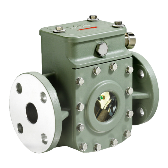
Figure 1: Protective relay RS 2001 1 Inspection window 2 Pressure equalization element Rear view Figure 2: Protective relay RS 2001 1 Dummy plug 2 Nameplate The protective relay RS 2001/R has an extra inspection window on the rear. 1800059/09 EN Maschinenfabrik Reinhausen GmbH 2018…
-
Page 17
3 Product description View from above Figure 3: Protective relay RS 2001 1 Gasket 2 Potential tie-in 3 Terminal box cover 4 Slotted head screw for potential tie-in 5 OPERATION (reset) test button 6 Slotted head screw for protective cover 7 OFF (test tripping) test button… -
Page 18: Nameplate
3 Product description 3.4 Nameplate The nameplate is on the back of the protective relay. Figure 4: Nameplate 3.5 Safety markings The following safety markings in accordance with DIN EN 60255-27 are used on the product: Figure 5: Overview of safety markings 1 Protective conductor connection 2 Notice, danger of electric shock 3 Notice, observe the documentation…
-
Page 19: Packaging, Transport And Storage
4 Packaging, transport and storage 4 Packaging, transport and storage 4.1 Packaging The products are sometimes supplied with sealed packaging and sometimes in a dry state, depending on requirements. Sealed packaging surrounds the packaged goods with plastic foil on all sides.
-
Page 20: Markings
4 Packaging, transport and storage 4.1.2 Markings The packaging bears a signature with instructions for safe transport and cor- rect storage. The following symbols apply to the shipment of non-hazardous goods. Adherence to these symbols is mandatory. Protect against Fragile Attach lifting Center of mass moisture…
-
Page 21: Storage Of Shipments
4 Packaging, transport and storage Visible damage If external transport damage is found upon receipt of the shipment, proceed as follows: ▪ Immediately record the identified transport damage in the shipping docu- ments and have this countersigned by the carrier. ▪…
-
Page 22: Unpacking Shipments And Checking For Transportation Damages
4 Packaging, transport and storage When selecting and setting up the storage location, ensure the following: ▪ Protect stored goods against moisture (flooding, water from melting snow and ice), dirt, pests such as rats, mice, termites and so on, and against unauthorized access.
-
Page 23: Mounting
5 Mounting 5 Mounting This chapter describes how to install and connect the protective relay. 5.1 Installing protective relay in piping and connecting Danger of explosion! WARNING Explosive gases in the protective relay can deflagrate or explode and result in severe injury or death. ►…
-
Page 24: Checking Function Of Protective Relay
5 Mounting ▪ The isolating device is to be rated such that the permissible disconnect times for protection against electric shock are complied with in accor- dance with the requirements of DIN VDE 0100-410, depending on the type of ground connection. ▪…
-
Page 25
5 Mounting 2. Remove the slotted head screw for potential tie-in and remove the termi- nal box cover with wire. Figure 7: Terminal box cover NOTICE Damage to protective relay! Damage to protective relay resulting from improper operation. ► Never press both test buttons at the same time. 3. -
Page 26
5 Mounting 4. Press OPERATION test button. ð Flap valve is vertical. Figure 9: OPERATION position 5. Position the wire for the terminal box cover and affix using the slotted head screw. Figure 10: Terminal box cover 1800059/09 EN Maschinenfabrik Reinhausen GmbH 2018… -
Page 27: Installing Protective Relay In Piping
5 Mounting 6. Attach the terminal box cover and secure with screws. Figure 11: Terminal box cover 5.1.3 Installing protective relay in piping Ensure the following for installation and proper function of the protective re- lay: 1. Prior to installing the protective relay, ensure that there are no foreign bodies in the piping or in the oil conservator.
-
Page 28
5 Mounting 7. The magnetic field strength (bushings, busbars etc.) must be < 20 kA/m. Higher field strengths have a negative effect on the function of the protec- tive relay. Figure 12: Pipe 1800059/09 EN Maschinenfabrik Reinhausen GmbH 2018… -
Page 29
5 Mounting 8. The reference arrow on the terminal box cover must point toward the on- load tap-changer’s oil conservator. Figure 13: Reference arrow pointing towards the on-load tap-changer’s oil conservator Maschinenfabrik Reinhausen GmbH 2018 1800059/09 EN… -
Page 30
5 Mounting 9. Install the protective relay horizontally in the pipe between on-load tap- changer head and oil conservator as near as possible to the on-load tap- changer head. Figure 14: Protective relay horizontal and with test button at the top 1800059/09 EN Maschinenfabrik Reinhausen GmbH 2018… -
Page 31: Making The Electrical Connections For The Protective Relay
5 Mounting 10. Install a stop-cock (nominal width of at least 25 mm) between protective relay and oil conservator. Figure 15: Stop-cock 5.1.4 Making the electrical connections for the protective relay The protective relay’s dry-reed magnetic switching tubes are supplied in the standard version as either NC or NO contacts.
-
Page 32
5 Mounting 1. Insert cable gland (RS 2001, 2001/V, 2001/H, 2001/E, 2001/5, 2001/R) or adapter (RS 2003 and RS 2004) in the tapped hole with the most favor- able position. Figure 16: Tapped hole 2. Seal open tapped hole with dummy plug. -
Page 33
5 Mounting 3. Loosen the three screws on the terminal box cover and lift off the terminal box cover. Figure 18: Terminal box cover 4. Take off the slotted head screw for potential tie-in and remove the termi- nal box cover with wire. Figure 19: Terminal box cover 5. -
Page 34
5 Mounting 6. Guide cable through cable gland and into protective relay. Ensure that the cable gland is well connected and sealed. Figure 21: Cable bushing 7. Connect the electric cables to the connection terminals in accordance with the connection diagram on the dimensional drawing. Figure 22: Electrical cables 1800059/09 EN Maschinenfabrik Reinhausen GmbH 2018… -
Page 35
5 Mounting 8. Connect protective conductor to cylinder head screw. Figure 23: Protective conductor 9. Insert the protective cover and secure using the screw. Figure 24: Protective cover Maschinenfabrik Reinhausen GmbH 2018 1800059/09 EN… -
Page 36: Checking Protective Relay
11. Attach the terminal box cover and secure with screws. Figure 26: Terminal box cover 5.2 Checking protective relay 5.2.1 Checking protective relay (RS 2001, 2001/V, 2001/H, 2001/E, 2001/5, 2001/R, 2001/T, 2003) ü Check that the protective relay is functioning correctly before commission- ing the transformer: 1.
-
Page 37: Checking Protective Relay (Rs 2004)
5 Mounting 4. Loosen the three screws on the terminal box cover and lift off the terminal box cover. 5. Remove the slotted head screw for potential tie-in and remove the termi- nal box cover with wire. 6. Press OFF test button. 7.
-
Page 38: Commissioning
6 Commissioning 6 Commissioning Once you have checked that the protective device is working correctly, you can continue by commissioning the transformer. To do so, follow the descrip- tion provided in the operating instructions for the on-load tap-changer. 1800059/09 EN Maschinenfabrik Reinhausen GmbH 2018…
-
Page 39: Operation
7 Operation 7 Operation The following chapter describes how to operate the protective relay. 7.1 Tripping the protective relay and re-commissioning the transformer Danger of explosion! WARNING Explosive gases in the protective relay can deflagrate or explode and result in severe injury or death. ►…
-
Page 40: Flap Valve In Off Position
7 Operation 7.1.2 Flap valve in OFF position Note that protective relay RS 2004 features an automatic reset mechanism which means that the flap valve does not remain in the OFF position after tripping. If the protective relay RS 2004 has not tripped due to an error in the tripping circuit, also proceed as described below for RS 2004.
-
Page 41: Maintenance
8 Maintenance 8 Maintenance DANGER Electric shock! Working on the transformer when the transformer is energized can lead to death or serious injuries. ► Switch off transformer on high and low-voltage side. ► Lock transformer to prevent unintentional restart. ► Ensure that everything is de-energized. ►…
-
Page 42: Inspection
8 Maintenance 8.1 Inspection Protective relay monitoring is limited to a function test. Interval Action Annually Check that the protective relay functions correctly. Table 4: Inspection plan 1800059/09 EN Maschinenfabrik Reinhausen GmbH 2018…
-
Page 43: Disposal
9 Disposal 9 Disposal For disposal, observe the national requirements applicable in the country of use. If you have any questions about disassembly and disposal, please contact Maschinenfabrik Reinhausen GmbH’s Technical Service department. Maschinenfabrik Reinhausen GmbH 2018 1800059/09 EN…
-
Page 44: Technical Data For Protective Relay
10 Technical data for protective relay 10 Technical data for protective relay The technical data for the protective relay RS 2001 is listed in the following. In accordance with DIN EN 60255-1, operational accuracy = base accuracy Housing Outdoor model…
-
Page 45
10 Technical data for protective relay Dielectric strength AC dielectric strength between all volt- 2,500 V, 50 Hz, test duration 1 minute age-carrying connections and the grounded parts AC dielectric strength between the 2,000 V, 50 Hz, test duration 1 minute opened contacts Table 8: Dielectric strength Electrical data for normally open (NO) dry-reed magnetic switch… -
Page 46
10 Technical data for protective relay Ambient conditions Ambient temperature Ta -40°C…+50°C Oil temperature <130 °C Air pressure Corresponds to 0 m…4,000 m above sea level Table 12: Ambient conditions 1800059/09 EN Maschinenfabrik Reinhausen GmbH 2018… -
Page 47: Protective Relay With Co Change-Over Contact As Tripping Switch
10 Technical data for protective relay 10.1 Protective relay with CO change-over contact as tripping switch The protective relay can be supplied with a dry-reed magnetic switch, CO change-over (variant 3) (see dimensional drawing supplied). Electrical data for CO change-over dry-reed magnetic switch Electrical data DC switching capacity 1.2 W…150 W…
-
Page 48: Protective Relay With Several Dry-Reed Magnetic Switches
10 Technical data for protective relay 10.2 Protective relay with several dry-reed magnetic switches The protective relay can be supplied with several independent dry-reed mag- netic switches. These can be designed as normally open (NO) or normally closed (NC) contacts and are electrically isolated (see dimensional drawing supplied).
-
Page 49: Glossary
Glossary Glossary Change-Over contact Normally Closed contact The International Electrotechnical Commission Normally Open contact (IEC for short) is involved in the preparation and publication of international standards for electri- cal, electronic and related technologies. National Pipe Thread (US thread standard) Ingress protection Maschinenfabrik Reinhausen GmbH 2018 1800059/09 EN…
-
Page 52
Maschinenfabrik Reinhausen GmbH Falkensteinstrasse 8 93059 Regensburg +49 (0)941 4090-0 +49(0)941 4090-7001 sales@reinhausen.com www.reinhausen.com 1800059/09 EN — RS — F0015207 — 06/18 — Maschinenfabrik Reinhausen GmbH 2018 THE POWER BEHIND POWER.
44
RS
The technical data for the protective relay RS 2001 is listed in the following.
In accordance with DIN EN 60255-1, operational accuracy = base accuracy
Housing
Degree of protection
Relay actuation
Weight
Oil flow speed of available types when
tripping (oil temperature 20°C)
Table 5: General technical data
Tripping circuit
The protective relay can be supplied with either a normally open (NO) or a
normally closed (NC) dry-reed magnetic switch (see dimensional drawing
supplied). Other contact combinations are available as a special version.
Electrical data for normally closed (NC) dry-reed magnetic switch
Electrical data
DC switching capacity
AC switching capacity (50 Hz)
Switching voltage AC/DC
Switched current AC/DC
Table 6: Electrical data
Switching capacity (switching load on an off)
Minimum switched current AC/DC (low-
est voltage)
Minimum switched current AC/DC (high-
est voltage)
Maximum switched current DC (highest
current)
Maximum switched current DC (highest
voltage)
Maximum switched current AC (highest
current)
Maximum switched current AC (highest
voltage)
Switching operations
Table 7: Switching capacity (switching load on an off)
10 Technical data for protective relay
Outdoor model
IP55
Flap valve with aperture
approx. 3.5 kg
0.65 ± 0.15 m/s
1.20 ± 0.20 m/s
3.00 ± 0.30 m/s
4.80 ± 0.30 m/s
1.2 W…200 W
1.2 VA…400 VA
24 V…250 V
4.8 mA…2 A
50 mA (at 24 V)
4.8 mA (at 250 V)
1.6 A (at 125 V with L/R = 40 ms)
0.9 A (at 250 V with L/R = 40 ms)
2 A (at 125 V with cos φ = 0.6)
1.6 A (at 250 V with cos φ = 0.6)
1,000 cycles
1800059/09 EN
Maschinenfabrik Reinhausen GmbH 2018
Download or browse on-line these Operating Instructions Manual for MR RS 2001 Relays.
Summary of Contents:
 |
[Page 1] MR RS 2001 Protective relay RS Operating instructions 1800059/09 EN |
 |
[Page 2] MR RS 2001 © All rights reserved by Maschinenfabrik Reinhausen Dissemination and reproduction of this document and use and disclosure of its content are strictly prohibited unless expressly permitted. Infringements will result in liability for compensation. Al… |
 |
[Page 3] MR RS 2001 Table of contents Maschinenfabrik Reinhausen GmbH 2018 31800059/09 EN RS Table of contents 1 Introduction…………………………………………………………………………………………………………. 5 1.1 Validity …….. |
 |
[Page 4] MR RS 2001 Table of contents Maschinenfabrik Reinhausen GmbH 20184 1800059/09 ENRS 5 Mounting …………………………………………………………………………………………………………… 23 5.1 Installing protective relay in pi… |
 |
[Page 5] MR RS 2001 1 Introduction Maschinenfabrik Reinhausen GmbH 2018 51800059/09 EN RS 1 Introduction This technical file contains detailed descriptions on the safe and proper in- stallation, connection, commissioning and monitoring of the product. It also includes s… |
 |
[Page 6] MR RS 2001 1 Introduction Maschinenfabrik Reinhausen GmbH 20186 1800059/09 ENRS The following documents are considered supporting documents: ▪ Supplements (included in the scope of delivery) ▪ Dimensional drawing (included in the scope of delivery) ▪ Rout… |
 |
[Page 7] MR RS 2001 1 Introduction Maschinenfabrik Reinhausen GmbH 2018 71800059/09 EN RS 1.6.1.3 Signal words and pictograms The following signal words are used: Signal word Definition DANGER Indicates a hazardous situation which, if not avoided, will result in death o… |
 |
[Page 8] MR RS 2001 1 Introduction Maschinenfabrik Reinhausen GmbH 20188 1800059/09 ENRS Important information. 1.6.3 Instruction system This technical file contains single-step and multi-step instructions. Single-step instructions Instructions which consist of only a s… |
 |
[Page 9] MR RS 2001 2 Safety Maschinenfabrik Reinhausen GmbH 2018 91800059/09 EN RS 2 Safety This technical file contains detailed descriptions on the safe and proper in- stallation, connection, commissioning and monitoring of the product. ▪ Read this technical file t… |
 |
[Page 10] MR RS 2001 2 Safety Maschinenfabrik Reinhausen GmbH 201810 1800059/09 ENRS Personal protective equipment Loosely worn or unsuitable clothing increases the danger of becoming trapped or caught up in rotating parts and the danger of getting caught on protruding p… |
 |
[Page 11] MR RS 2001 2 Safety Maschinenfabrik Reinhausen GmbH 2018 111800059/09 EN RS Safety markings Warning signs and safety information plates are safety markings on the product. They are an important aspect of the safety concept. ▪ Observe all safety markings on th… |
 |
[Page 12] MR RS 2001 2 Safety Maschinenfabrik Reinhausen GmbH 201812 1800059/09 ENRS Electrically skilled person The electrically skilled person has a technical qualification and therefore has the required knowledge and experience, and is also conversant with the ap- pli… |
 |
[Page 13] MR RS 2001 2 Safety Maschinenfabrik Reinhausen GmbH 2018 131800059/09 EN RS Personal protective equipment to be worn at all times Protective clothing Close-fitting work clothing with a low tearing strength, with tight sleeves and with no protrud- ing parts. It … |
 |
[Page 14] MR RS 2001 2 Safety Maschinenfabrik Reinhausen GmbH 201814 1800059/09 ENRS NOTICE Damage to protective relay, on-load tap-changer and trans- former! If the protective relay is dried in a furnace, this may cause damage to the protective relay and restrict its co… |
 |
[Page 15] MR RS 2001 3 Product description Maschinenfabrik Reinhausen GmbH 2018 151800059/09 EN RS 3 Product description This chapter contains an overview of the design and function of the product. 3.1 Scope of delivery The product is packaged with protection against moi… |
 |
[Page 16] MR RS 2001 3 Product description Maschinenfabrik Reinhausen GmbH 201816 1800059/09 ENRS 3.3 Design/versions Front view Figure1: Protective relay RS 2001 1 Inspection window 2 Pressure equalization element Rear view Figure2: Protective relay RS 2001 1 Dumm… |
 |
[Page 17] MR RS 2001 3 Product description Maschinenfabrik Reinhausen GmbH 2018 171800059/09 EN RS View from above Figure3: Protective relay RS 2001 1 Gasket 2 Potential tie-in 3 Terminal box cover 4 Slotted head screw for potential tie-in 5 OPERATION (reset) test but… |
 |
[Page 18] MR RS 2001 3 Product description Maschinenfabrik Reinhausen GmbH 201818 1800059/09 ENRS 3.4 Nameplate The nameplate is on the back of the protective relay. Figure4: Nameplate 3.5 Safety markings The following safety markings in accordance with DIN EN 60255-2… |
 |
[Page 19] MR RS 2001 4 Packaging, transport and storage Maschinenfabrik Reinhausen GmbH 2018 191800059/09 EN RS 4 Packaging, transport and storage 4.1 Packaging The products are sometimes supplied with sealed packaging and sometimes in a dry state, depending on requireme… |
 |
[Page 20] MR RS 2001 4 Packaging, transport and storage Maschinenfabrik Reinhausen GmbH 201820 1800059/09 ENRS 4.1.2 Markings The packaging bears a signature with instructions for safe transport and cor- rect storage. The following symbols apply to the shipment of non-ha… |
 |
[Page 21] MR RS 2001 4 Packaging, transport and storage Maschinenfabrik Reinhausen GmbH 2018 211800059/09 EN RS Visible damage If external transport damage is found upon receipt of the shipment, proceed as follows: ▪ Immediately record the identified transport damage i… |
 |
[Page 22] MR RS 2001 4 Packaging, transport and storage Maschinenfabrik Reinhausen GmbH 201822 1800059/09 ENRS When selecting and setting up the storage location, ensure the following: ▪ Protect stored goods against moisture (flooding, water from melting snow and ice),… |
 |
[Page 23] MR RS 2001 5 Mounting Maschinenfabrik Reinhausen GmbH 2018 231800059/09 EN RS 5 Mounting This chapter describes how to install and connect the protective relay. 5.1 Installing protective relay in piping and connecting WARNING Danger of explosion! Explosive gas… |
 |
[Page 24] MR RS 2001 5 Mounting Maschinenfabrik Reinhausen GmbH 201824 1800059/09 ENRS ▪ The isolating device is to be rated such that the permissible disconnect times for protection against electric shock are complied with in accor- dance with the requirements of DIN … |
 |
[Page 25] MR RS 2001 5 Mounting Maschinenfabrik Reinhausen GmbH 2018 251800059/09 EN RS 2. Remove the slotted head screw for potential tie-in and remove the termi- nal box cover with wire. Figure7: Terminal box cover NOTICE Damage to protective relay! Damage to protec… |
 |
[Page 26] MR RS 2001 5 Mounting Maschinenfabrik Reinhausen GmbH 201826 1800059/09 ENRS 4. Press OPERATION test button. ð Flap valve is vertical. Figure9: OPERATION position 5. Position the wire for the terminal box cover and affix using the slotted head screw. Figure… |
 |
[Page 27] MR RS 2001 5 Mounting Maschinenfabrik Reinhausen GmbH 2018 271800059/09 EN RS 6. Attach the terminal box cover and secure with screws. Figure11: Terminal box cover 5.1.3 Installing protective relay in piping Ensure the following for installation and proper f… |
 |
[Page 28] MR RS 2001 5 Mounting Maschinenfabrik Reinhausen GmbH 201828 1800059/09 ENRS 7. The magnetic field strength (bushings, busbars etc.) must be < 20 kA/m. Higher field strengths have a negative effect on the function of the protec- tive relay. Figure12: Pipe… |
 |
[Page 29] MR RS 2001 5 Mounting Maschinenfabrik Reinhausen GmbH 2018 291800059/09 EN RS 8. The reference arrow on the terminal box cover must point toward the on- load tap-changer’s oil conservator. Figure13: Reference arrow pointing towards the on-load tap-chang… |
 |
[Page 30] MR RS 2001 5 Mounting Maschinenfabrik Reinhausen GmbH 201830 1800059/09 ENRS 9. Install the protective relay horizontally in the pipe between on-load tap- changer head and oil conservator as near as possible to the on-load tap- changer head. Figure14: Protec… |
 |
[Page 31] MR RS 2001 5 Mounting Maschinenfabrik Reinhausen GmbH 2018 311800059/09 EN RS 10. Install a stop-cock (nominal width of at least 25 mm) between protective relay and oil conservator. Figure15: Stop-cock 5.1.4 Making the electrical connections for the protecti… |
 |
[Page 32] MR RS 2001 5 Mounting Maschinenfabrik Reinhausen GmbH 201832 1800059/09 ENRS 1. Insert cable gland (RS 2001, 2001/V, 2001/H, 2001/E, 2001/5, 2001/R) or adapter (RS 2003 and RS 2004) in the tapped hole with the most favor- able position. Figure16: Tapped hole… |
 |
[Page 33] MR RS 2001 5 Mounting Maschinenfabrik Reinhausen GmbH 2018 331800059/09 EN RS 3. Loosen the three screws on the terminal box cover and lift off the terminal box cover. Figure18: Terminal box cover 4. Take off the slotted head screw for potential tie-in and r… |
 |
[Page 34] MR RS 2001 5 Mounting Maschinenfabrik Reinhausen GmbH 201834 1800059/09 ENRS 6. Guide cable through cable gland and into protective relay. Ensure that the cable gland is well connected and sealed. Figure21: Cable bushing 7. Connect the electric cables to the… |
 |
[Page 35] MR RS 2001 5 Mounting Maschinenfabrik Reinhausen GmbH 2018 351800059/09 EN RS 8. Connect protective conductor to cylinder head screw. Figure23: Protective conductor 9. Insert the protective cover and secure using the screw. Figure24: Protective cover … |
 |
[Page 36] MR RS 2001 5 Mounting Maschinenfabrik Reinhausen GmbH 201836 1800059/09 ENRS 10. Position the wire for the terminal box cover and affix using the slotted head screw. Figure25: Terminal box cover 11. Attach the terminal box cover and secure with screws. Figur… |
 |
[Page 37] MR RS 2001 5 Mounting Maschinenfabrik Reinhausen GmbH 2018 371800059/09 EN RS 4. Loosen the three screws on the terminal box cover and lift off the terminal box cover. 5. Remove the slotted head screw for potential tie-in and remove the termi- nal box cover wit… |
 |
[Page 38] MR RS 2001 6 Commissioning Maschinenfabrik Reinhausen GmbH 201838 1800059/09 ENRS 6 Commissioning Once you have checked that the protective device is working correctly, you can continue by commissioning the transformer. To do so, follow the descrip- tion provid… |
 |
[Page 39] MR RS 2001 7 Operation Maschinenfabrik Reinhausen GmbH 2018 391800059/09 EN RS 7 Operation The following chapter describes how to operate the protective relay. 7.1 Tripping the protective relay and re-commissioning the transformer WARNING Danger of explosion! … |
 |
[Page 40] MR RS 2001 7 Operation Maschinenfabrik Reinhausen GmbH 201840 1800059/09 ENRS 7.1.2 Flap valve in OFF position Note that protective relay RS 2004 features an automatic reset mechanism which means that the flap valve does not remain in the OFF position after tri… |
 |
[Page 41] MR RS 2001 8 Maintenance Maschinenfabrik Reinhausen GmbH 2018 411800059/09 EN RS 8 Maintenance DANGER Electric shock! Working on the transformer when the transformer is energized can lead to death or serious injuries. ► Switch off transformer on high and low… |
 |
[Page 42] MR RS 2001 8 Maintenance Maschinenfabrik Reinhausen GmbH 201842 1800059/09 ENRS 8.1 Inspection Protective relay monitoring is limited to a function test. Interval Action Annually Check that the protective relay functions correctly. Table4: Inspection plan … |
 |
[Page 43] MR RS 2001 9 Disposal Maschinenfabrik Reinhausen GmbH 2018 431800059/09 EN RS 9 Disposal For disposal, observe the national requirements applicable in the country of use. If you have any questions about disassembly and disposal, please contact Maschinenfabrik R… |
 |
[Page 44] MR RS 2001 10 Technical data for protective relay Maschinenfabrik Reinhausen GmbH 201844 1800059/09 ENRS 10 Technical data for protective relay The technical data for the protective relay RS 2001 is listed in the following. In accordance with DIN EN 60255-1, op… |
 |
[Page 45] MR RS 2001 10 Technical data for protective relay Maschinenfabrik Reinhausen GmbH 2018 451800059/09 EN RS Dielectric strength AC dielectric strength between all volt- age-carrying connections and the grounded parts 2,500 V, 50 Hz, test duration 1 minute AC diel… |
 |
[Page 46] MR RS 2001 10 Technical data for protective relay Maschinenfabrik Reinhausen GmbH 201846 1800059/09 ENRS Ambient conditions Ambient temperature Ta -40°C…+50°C Oil temperature <130 °C Air pressure Corresponds to 0 m…4,000 m above sea level Table12: … |
 |
[Page 47] MR RS 2001 10 Technical data for protective relay Maschinenfabrik Reinhausen GmbH 2018 471800059/09 EN RS 10.1 Protective relay with CO change-over contact as tripping switch The protective relay can be supplied with a dry-reed magnetic switch, CO change-over (… |
 |
[Page 48] MR RS 2001 10 Technical data for protective relay Maschinenfabrik Reinhausen GmbH 201848 1800059/09 ENRS 10.2 Protective relay with several dry-reed magnetic switches The protective relay can be supplied with several independent dry-reed mag- netic switches. Th… |
 |
[Page 49] MR RS 2001 Glossary Maschinenfabrik Reinhausen GmbH 2018 491800059/09 EN RS Glossary CO Change-Over contact IEC The International Electrotechnical Commission (IEC for short) is involved in the preparation and publication of international standards for electri- … |
 |
[Page 50] MR RS 2001 … |
 |
[Page 51] MR RS 2001 … |
 |
[Page 52] MR RS 2001 Maschinenfabrik Reinhausen GmbH Falkensteinstrasse 8 93059 Regensburg +49 (0)941 4090-0 +49(0)941 4090-7001 [email protected] www.reinhausen.com 1800059/09 EN — RS — F0015207 — 06/18 — Maschinenfabrik Reinhausen GmbH 2018 THE POWER BEHIND POWER. … |
Types of Manuals:
The main types of MR RS 2001 instructions:
- User guide — rules of useing and characteristics
- Service manual — repair, diagnostics, maintenance
- Operation manual — description of the main functions of equipment
Relays Instructions by MR:
-
WAGO WAGO-I/O-SYSTEM 750-508
Pos: 2 /Dokumentatio n allgemein/Einband/Ei nband Deckblatt @ 9\mod_12 85229289866_0.doc @ 64941 @ @ 1 Manual WAGO-I/O-SYSTEM 7502DO 24V DC 2.0A, diagnostics750-5082-Channel Digital Output Module DC 24 V, short-circuit protected; high-side switching, with diagnosticsVersion 1.2.0 Pos: 3 /Alle Serien (Al lgeme …
WAGO-I/O-SYSTEM 750-508 Control Unit, 52
-
Pilz PNOZ X Series
— 1 -Sicherheitsbestimmungen• Das Gerät darf nur von Personen installiertund in Betrieb genommen werden, die mitdieser Betriebsanleitung und den gelten-den Vorschriften über Arbeitssicherheitund Unfallverhütung vertraut sind.Beachten Sie die VDE- sowie die örtlichenVorschriften, insbesondere hinsichtlich derSchut …
PNOZ X Series Relays, 16
-
Allen-Bradley Guardmaster MINOTAUR MSR121RT
Deutsch / FrançaisMINOTAURMSR121RTMONITORING SAFETY RELAYÜBERWACHUNGS-/SICHERHEITSRELAISRELAIS DE SECURITE POUR CONTROLEEinbauanleitung(b) Installation InstructionsNotice D’installationRETAIN THESE INSTRUCTIONSInstallation must be in accordance with the following steps and must be carried out by suitably compete …
Guardmaster MINOTAUR MSR121RT Relays, 4
-
Pilz PNOZ X2.3P
— 1 -Safety Regulations• The unit may only be installed andoperated by personnel who are familiarwith both these instructions and thecurrent regulations for safety at work andaccident prevention. Follow VDE andlocal regulations especially as regardspreventative measures.• Transport, storage and operating conditions …
PNOZ X2.3P Relays, 16
-
golmar SAR-12/18
Mod.GTwin50123709 DS551209-001ALBT20579UNITA’ RELE’ SAR-12/18RELAY UNIT SAR-12/18 UNITÉ RELAIS SAR-12/18UNIDAD RELÉ SAR-12/18EINHEIT RELAIS SAR-12/18RELAIS UNIT SAR-12/18Ref. 12091012PS -6-J~0~12 …
SAR-12/18 Relays, 8
-
GE N60
847710A1.CDRN60 Revision: 5.7xManual P/N: 1601-0125-U4 (GEK-113529C)N60 Network Stability and Synchrophasor Measurement SystemUR Series Instruction ManualGE Digital Energy650 Markland StreetMarkham, OntarioCanada L6C 0M1Tel: +1 905 927 7070 Fax: +1 905 927 5098Internet: http://www.GEDigitalEnergy.comTitle PageIISO 9 …
N60 Measuring Instruments, 544
-
Bticino 3584C
3584C07/21-01 PCLE10357ADBTicino SpA – Viale Borri, 231 – 21100 Varese – Italy – www.bticino.com1. Бутон за управление2. Бутон за ресетиране3. LED индикатор4. Клеми за свързване1. Upravljačka tipka2. Tipka za resetiranje3. Signalna led lampica4. …
3584C Relays, 4
-
Sel SEL-751A
Package Contents Panel Cutout Template Manual CD & ACSELERATOR QuickSet® Software CDNo. 8-32 Mounting Screws, Gasket, & Serial Port CoverConfigurable Label Kit (if equipped)Label Removal ToolBlank Pushbutton …
SEL-751A Relays, 8
Струйное реле RS-1000 предназначено для защиты контакторов РПН от повреждений, при которых возникает ускоренный поток масла из бака контактора в расширитель. Неисправности контакторов РПН возникают вследствие старения и износа силовых контактов, разрушения изоляционных слоев, ослабление пружин механизма контактора, приводящие к замедлению и нечеткому переключению контактора, затянувшейся дуге, бурному разложению масла.
Струйные реле RS-1000 устанавливаются на трансформаторах с устройством ЛРН, изготовленных в Болгарии. Как и реле ÜRF 25/10, реле RS-1000 реагирует только на скорость потока масла, однако имеет только одну уставку 0.9 м/с.
Конструкция реле RS-1000 в основном аналогична конструкции реле ÜRF 25/10. Реагирующий элемент расположен со стороны бака контактора и нормально удерживается в начальном положении. При возникновении повреждения струя масла создает давление на пластину, что приводит к ее повороту и срабатыванию ртутных контактов реле. После срабатывания пластина фиксируется в конечном положении с помощью защелки, поэтому контакты остаются замкнутыми до возврата реле вручную.
Для возврата реле в начальное положение необходимо нажать на кнопку «Включено», находящуюся под верхней крышкой. В отличие от реле ÜRF 25/10 реле RS-1000 имеет отдельную кнопку для проверки работоспособности- «Выключено». При нажатии на кнопку «Выключено» тяги отключающей пластины переходят в конечное положение и контакты замыкаются. У струйных реле кран для отбора проб газа отсутствует и нет делений на смотровых стеклах, поскольку в процессе эксплуатации нет необходимости выпускать газ из реле или контролировать его наличие.