|
|||
|
|||
|
|||
|
|||
|
|||
|
|||
|
|||
|
|||
|
|||
|
|||
|
|||
|
|||
|
|||
|
|||
|
|||


![[непонятно]](https://www.proektant.org/Smileys/default/huh.gif "[непонятно]")
Сейчас Вы — Гость на форумах «Проектант». Гости не могут писать сообщения и создавать новые темы.
Преодолейте несложную формальность — зарегистрируйтесь! И у Вас появится много больше возможностей на форумах «Проектант».
Последние сообщения на форуме «Автоматизация, Связь, Сигнализация»
30 Августа 2023 года, 16:50
17 Августа 2023 года, 11:32
17 Августа 2023 года, 11:27
17 Августа 2023 года, 11:17
13 Августа 2023 года, 03:32
08 Августа 2023 года, 15:26
-
Contents
-
Table of Contents
-
Bookmarks
Quick Links
Orion ISS
ISO 9001
Access Controller
S2000-2
User’s Manual
Related Manuals for bolid S2000-2
Summary of Contents for bolid S2000-2
-
Page 1
Orion ISS ISO 9001 Access Controller S2000-2 User’s Manual… -
Page 2
The S2000-2 rev.01 access controller is equipped with twofold increased memory capacity for access keys (8192 keys), as well as event buffer capacity (4095 events) against the S2000-2 controller. All information presented in this Manual is applicable for both controllers taking this difference into ac- count. -
Page 3: Table Of Contents
Remote Control via RS-485 interface…………….46 Installation……………………..47 Standard Delivery ……………………48 S2000-2 Mounting ……………………48 S2000-2 PCB Layout ……………………49 Wiring the S2000-2 for Two Entrance Doors Mode …………..50 Wiring the S2000-2 for One Entrance/Exit Door Mode…………… 52 www.bolid.com…
-
Page 4
Condition Inspection of Readers’ Connection Circuits …………92 Condition Inspection of LOOP, DOOR and EXIT Circuits……….93 Appendix Connecting Some Models of Readers to the S2000-2 Controller….. 95 Bolid S2000-Proxy / S2000-Proxy N Reader Connection …………96 Bolid Proxy-2A / Proxy-3A Reader Connection…………….96 PR-A03 / PR-A05 / PR-P09 Reader Connection……………..97… -
Page 5: Features And Design
S2000-2 Features and Design FEATURES AND DESIGN www.bolid.com…
-
Page 6
Orion ISS The S2000-2 access controller (hereinafter referred to as the controller) is designed to control access through one or two access points by means of reading presented access keys (Proximity cards, iBut- tons, PIN-codes and so on), verification of access rights and closing (opening) relay contacts that operate locking units (electromagnetic locks and strikes, turnstiles, swing-beam drives and so on). -
Page 7
LEDs and sounder, and by means of LEDs and sounder of the reader. The controller view is shown in Figure 1. The green READY LED is designed to indicate S2000-2 op- eration conditions while the two red LEDs 1 and 2 are intended to provide access and arm- ing/disarming indication. -
Page 8
Orion ISS www.bolid.com… -
Page 9: Specifications
S2000-2 Specifications SPECIFICATIONS www.bolid.com…
-
Page 10
+5 V CMOS levels Controlled by logical +5 V CMOS levels Sounder Memory Capacity 4096 (S2000-2) or 8192 (S2000-2 rev.01) key codes Event Log 2047 (S2000-2) or 4095 (S2000-2 rev.01) events Time Schedules 16 separate time schedules each including 10 time zones active for entry and/or for exit (loop 1 and/or 2 arm- ing/disarming). -
Page 11
S2000-2 Specifications Request-to-Exit Inputs Alarm Inputs 2 inputs to monitor intruder detectors’ conditions (except for Swing-beam Barrier operation mode) Wire Resistance 1 kOhm excluding termination resistance 8.2 kOhm Relay Outputs 2 outputs to operate locking units or power relays 30VDC… -
Page 12
Orion ISS www.bolid.com… -
Page 13: Operating
S2000-2 Operating OPERATING www.bolid.com…
-
Page 14: Access Keys
The keys which are used to operate with the controller must be pre-programmed and stored either in the S2000-2 controller memory or in the ARM Orion database. All controller keys fall into four different classes (types): User keys used for access and arming/disarming…
-
Page 15
Moreover, access control based on five different key patterns can be implemented through the access point. In such a case the codes of presented keys are stored neither in the S2000-2 memory nor in ARM Orion database, but instead to gain access they must meet on of the controller key pattern (see Key Pattern Based Access Control Section below). -
Page 16: Operation Modes
If door sensors are connected to the relevant terminals of the controller and the controller is pro- grammed to use these ones, some extended features are available for the S2000-2 controller, among them: −…
-
Page 17: One Entrance/Exit Door Mode
However a regular door does not protect against tailgating. If door sensors are connected to the relevant terminals of the controller and the controller is pro- grammed to use these ones, some extended features are available for the S2000-2 controller, among them: −…
-
Page 18: Turnstile Mode
Orion ISS vation Time parameter, but at least for two seconds, regardless of the time the passing actually takes In order to pass in both directions, a User identifier with the Access attribute is to be presented to a reader mounted near the entrance/exit. If the identification process is completed successfully, the reader sounder generates two beeps, the green LED lights, the door is opened (unlocked) and the ACCESS GRANTED message is generated with the code of key presented included.
-
Page 19: Swing-Beam Barrier Mode
S2000-2 Operating In order to pass in any direction, a User key with the Access attribute set is to be presented to a reader installed before the turnstile. If identification is completed successfully, the reader sounder generates two beeps, the green LED lights, the turnstile is unlocked to provide one passage in specified direction, and the ACCESS GRANTED message is generated with the code of the presented key included.
-
Page 20: Two Sluice Doors Mode
Orion ISS When driving to the swing-beam barrier, a car is slowing down near the reader, the driver presenting its User key with Access attribute set on. If access is granted the green LED of the reader (green light on the traffic control unit) is switched on and the ACCESS GRANTED message is generated with the code of the presented key included.
-
Page 21
S2000-2 Operating example, compare the person who entered with an image on the PC monitor) and then make an egress decision. The standard time to enter the sluice after access being granted is 10 seconds. The standard time to leave the sluice after the EXIT button being pressed is 10 seconds. -
Page 22: Access Modes
In the Free Pass mode a door (turnstile, swing-beam barrier) is permanently open for free passing (without identification and passage detection). In the Free Pass or Access Locked modes the S2000-2 controller takes into account only special keys (Unlocking, Locking or Master), as well as keys intended for loop and partition arming/disarming. Pre- senting an Unlocking or Locking key restores the Controlled access mode –…
-
Page 23: Access Locked By Arming Of Access Locking Alarm Loops
S2000-2 Operating Switching to the Controlled mode can be implemented by: − repeated presenting the Locking key, or − presenting the Unlocking key, or − the relevant command of the network controller, received via the RS-485 interface Access Locked by Arming of Access Locking Alarm Loops…
-
Page 24: Controlled Access Mode
Orion ISS Controlled Access Mode In the controlled mode the controller provides both local and centralized access. Local access in controlled mode is granted for owners of those identifiers (keys) which: − are stored in the controller database, − are not locked currently, −…
-
Page 25: Operating Principles
User type and intended for access or access + loop arming/disarming (combined). The S2000-2 controller verifies if the key presented is stored in its database, has relevant access rights, does not violate access rules and meets all required conditions to gain access.
-
Page 26
An ACCESS DENIED message is generated. If the key code is not stored in the controller database and communication with the network controller is lost (the S2000-2 operates standalone), access is denied as follows: − The controller and reader sounders generate a long Error sound −… -
Page 27: Alarm Loop Arming/Disarming
S2000-2 Operating armed partition will be armed, and vice versa). The condition of the partition is indicated by the reader LEDs within 30 seconds or until another identifier is presented. When the EXIT button is pressed, access is granted, but the ACCESS GRANTED message is gener- ated without indicating a key code (impersonal).
-
Page 28: Alarm Loops
Arming Request button (or coupling iButton reader contacts). The S2000-2 controller can be programmed so that its loop arming causes the controller to lock local access via any reader’s controlled area in accordance with one of the following ways (see Lock Ac- cess If……
-
Page 29
Time to Hold Keys for Arming/Disarming. Arming/disarming commands are delivered to the controller via the RS-485 interface the S2000-2 is controlled from a PC, from a S2000/S20000M control console or from one of Orion system devices by using partition arming/disarming mechanism. -
Page 30
Orion ISS Besides, reader’s LEDs can display armed (red lighting) and disarmed (LED is off) conditions of the following loops combinations (defined by Normal Mode Condition parameter see Reader Configu- ration Parameters Section of this Manual): − Alarm loop 1 only −… -
Page 31: Two Factor Authentication
Authentication flag (see the description of this configuration parameter in Reader Configuration Pa- rameters Section of this Manual). The main and additional keys are presented to the same reader of the S2000-2 controller, that is why combinations of different keys can be used only with special combined readers providing reading dif- ferent keys and transmitting them to the S2000-2 controller in a single format (Touch Memory, Wie- gand, or ABA TRACK II).
-
Page 32: Access Rights
Orion ISS ACCESS RIGHTS To simplify description of the access rights for each key as well as rights to arm/disarm the controller’s alarm loops the Access Group category is used. Each access group is described as a set of rights and restrictions applied for a group of the keys (users).
-
Page 33
If a two or three access rule is given for an access group of the presented, the IDENTIFICATION message is generated by the S2000-2 controller, the green LED of the reader starts flashing 5 times per second, and the controller waits during the next 30 seconds for the presenting the key (the keys) assigned with the access group (groups) required to confirm the access rights of the presented key. -
Page 34: Time Schedules
In order to implement time limitations on user access rights (to control access depending on date, day of the week or time) up to 16 different time schedules can be described for the S2000-2 controller, these time schedules being assigned to relevant access groups.
-
Page 35: Anti-Passback Rules
S2000-2 controller outage will not cause the clock failure, time limitations operating cor- rectly after the controller starting up again. Meanwhile, one should be kept in mind that if the S2000-2 controller operates standalone for a long time its clock can shift. That is why it is not recommended to use time schedules while the controller operates in standalone mode without a network controller: all time schedules for all access groups should have the number 0.
-
Page 36
The Timed Anti-passback rule uses an additional Anti-passback Lockout Reriod parameter. During this time period since passing to an access zone the S2000-2 controller is operating as for Hard Anti- passback rule (repeated access requests to the zone without exiting it are rejected and ACCESS DENIED messages are generated). -
Page 37
An anti-passback rule can be made stronger by setting the Zonal Anti-passback (‘Entry/Exit Control’). If this parameter is set for an access group the S2000-2 controller takes into account all passages of key owners assigned to the access group to all the access zones programmed within the system. If… -
Page 38: Centralized Access Control And Alarm Loop Arming/Disarming
S2000-2 which ‘knows’ the key code. Centralized control means that key codes are stored not in the memory of a S2000-2 but in the memory of a network controller. When the Orion system operates under ARM Orion Workstation the owner of any key stored in Orion database can gain access through any system access point that is permitted for this key or arm/disarm any permitted alarm loop in the system.
-
Page 39
Flashes once for a second Yellow (green + red) If the key unknown to the S2000-2 is presented to one of its readers when the communications be- tween the controller and the network controller is lost, the ACCESS DENIED message is generated. -
Page 40: Key Pattern Based Access Control
When a key is presented to a reader of the S2000-2 controller the controller first checks if the pre- sented key code is stored in its database. If the key code is not found in the controller memory, it is checked against the first access key pattern, then against the second one, etc.
-
Page 41
S2000-2 Operating meets the pattern) and specify the pattern mask (its ‘opened’ positions) which will be allied to codes of presented keys. Finally, the access group and validity period must be specified for the pattern (see Access Key Pattern Configuration Parameters Section of this Manual). -
Page 42: Light And Sound Alarms
The indication of reader LEDs is similar to that of the 1 and 2 controller LEDs and is shown in Table 3. The behavior of reader sounders is similar to the behavior of the S2000-2 sounder and is shown in Table 4.
-
Page 43
S2000-2 Operating Condition/Event Lighting Mode Color Yellow Centralized partition control, the partition is armed (Red + Green) Centralized partition control, the partition is dis- – armed Yellow Centralized partition control, an alarm within the Flashes twice per second partition (Red + Green) -
Page 44
Programming, or Loop Alarms) both for the C2000-2 built-in sounder and each sounder of the readers individually. It can be done while programming the relevant parameters of S2000-2 by means of the UProg Configuration Tool see S2000-2 Programming Section of this Manual. -
Page 45: Data Communications Via Rs-485 Interface
GSM, Internet and so Condition Message Transmission The S2000-2 controller is designed to send automatically condition and trouble messages to a net- work controller through RS-485 interface line, among them:…
-
Page 46: Remote Control Via Rs-485 Interface
S2000-2 clock. The event buffer capacity is 2047 events for a S2000-2 or 4095 events for a S2000-2 rev.01. Remote Control via RS-485 interface…
-
Page 47: Installation
S2000-2 Installation INSTALLATION www.bolid.com…
-
Page 48: Standard Delivery
To remove the cover press here and pull out Figure 2. S2000-2 Overall and Mounting Dimensions The S2000-2 controller is to be mounted on walls and other constructions within remises which are protected against atmospheric fallouts, mechanical damage and unauthorized access.
-
Page 49: S2000-2 Pcb Layout
S2000-2 Installation S2000-2 PCB LAYOUT The layout of the S2000-2 access controller PCB is shown in Figure 3. LOOP2 LOOP1 LOOP2 LOOP2 Figure 3. S2000-2 PCB Layout www.bolid.com…
-
Page 50: Wiring The S2000-2 For Two Entrance Doors Mode
WIRING THE S2000-2 FOR TWO ENTRANCE DOORS MODE Figure 4 shows the wiring diagram for a S2000-2 controller operating in the Two Entrance Doors mode. In this operating mode alarm loops are not involved in access strategy and are not shown in the connection diagram.
-
Page 51
DOOR2 RS-485 GND2 EXIT2 8.2 kOhm EXIT XT3.2 Lock/Strike To the Lock/Strike Power Supply XT3.3 Reader 2 BEEP2 BEEP LEDR2 LEDR LEDG2 LEDG D1-2 D0-2 +12V2 +12V GND2 Figure 4. S2000-2 Wiring for the Two Entrance Doors Operation Mode www.bolid.com… -
Page 52: Wiring The S2000-2 For One Entrance/Exit Door Mode
WIRING THE S2000-2 FOR ONE ENTRANCE/EXIT DOOR MODE Wiring diagram for a S2000-2 controller operating in the One Entrance/Exit Door mode is given in Figure 5. In this operation mode alarm loops are not involved in access strategy and are not shown in the connection diagram.
-
Page 53
XT1.2 Reader 1 RS-485 Reader 2 XT3.2 BEEP2 BEEP LEDR2 LEDR LEDG2 LEDG D1-2 D0-2 +12V2 +12V GND2 * – ENTRANCE and EXIT buttons are used if required Figure 5. S2000-2 Wiring for the One Entrance/Exit Door Operation Mode www.bolid.com… -
Page 54: Wiring The S2000-2 For Turnstile Mode
GND2 Passage Sensor 1 EXIT2 8.2 kOhm Access zone XT1.2 controlled by EXIT* Reader 1 RS-485 Reader 2 XT3.3 BEEP2 BEEP LEDR2 LEDR LEDG2 LEDG D1-2 D0-2 +12V2 +12V GND2 Figure 6. S2000-2 Wiring for the Turnstile Operation Mode www.bolid.com…
-
Page 55
However they can be used as intruder alarm loops in the Orion system in which the S2000-2 controller operates on-line (see Alarm Loops Section of this Manual). -
Page 56: Wiring The S2000-2 For Swing-Beam Barrier Mode
(near the swing-beam). In such a case it is wired in parallel across the relevant inputs of both control channel of S2000-2 as shown in Figure 7. Along with the LEDs of the readers (or instead of them) two traffic lights operated by +5 V CMOS logic signals can be connected to the LEDG1, LEDR1 and LEDG2, LEDR2 terminals of the controller.
-
Page 57
Car Presence Detector LOOP2- 9 RIP-12 XT1.2 +12V +12V Access zone Reader 2 XT3.3 controlled by BEEP2 BEEP Reader 1 LEDR2 LEDR LEDG2 LEDG D1-2 D0-2 +12V2 +12V GND2 Figure 8. S2000-2 Wiring for the Swing-beam Barrier Operation Mode www.bolid.com… -
Page 58
LOOP1(2)- 2(4) Figure 9. NC Car Presence Sensor to LOOP1 and LOOP2 S2000-2 Terminals Wiring Diagram If reader current consumption exceeds 100 mA or the readers are located far from the controller (100m and more), they must be wired directly to the power supply (the connection diagram shows the readers are powered via the controller terminals). -
Page 59: Wiring The S2000-2 For Two Sluice Doors Mode
EXIT2 Lock RIP-12 EXIT 2 XT1.2 +12 V +12V DOOR 2 Reader 2 Door Sensor 2 XT3.2 BEEP2 BEEP LEDR2 LEDR LEDG2 LEDG D1-2 D0-2 +12V2 +12V GND2 Figure 10. S2000-2 Wiring for the Two Sluice Doors Operation Mode www.bolid.com…
-
Page 60
Orion ISS Wiring of a S2000-2 controller operating in Two Sluice Doors mode is shown in Figure 10. In this op- eration mode alarm loops are not involved in access strategy and are not shown in the connection diagram. However they can be used as intruder alarm loops in the Orion system in which the S2000-2 controller operates on-line (see Alarm Loops Section of this Manual). -
Page 61: Connecting Readers
For example, the Proximity card code in the Wiegand-44 format for the S2000-2 controller in most cases is compatible with the card code in the Touch Memory format, i.e. if a reader with the Wiegand-44 interface is used for entering the card…
-
Page 62: Connecting Dallas Ibutton Readers
) If a reader is equipped with a single LED control circuit this circuit is to be connected to the LEDG terminal of S2000-2, with LEDR terminal being left unconnected 2) If a reader is equipped with no built-in sounder the BEEP terminal of the S2000-2 controller is to be left unconnected Figure 13.
-
Page 63: Connecting Readers With Wiegand Output Interface
) If a reader is equipped with a single LED control circuit this circuit is to be connected to the LEDG terminal of S2000-2, with LEDR terminal being left unconnected 2) If a reader is equipped with no built-in sounder the BEEP terminal of the S2000-2 controller is to be left unconnected Figure 14.
-
Page 64: Connecting Door Or Passage Sensors
If none of these functions is required these circuits can be out of use and the relevant terminals are to be left disconnected only if the S2000-2 controller operates in the Two Entrance Doors, One En- trance/Exit Door and Turnstile modes. In the Swing-beam Barrier and Two Sluice Doors modes using DOOR1 and DOOR2 circuits and connecting passage sensors are obligatory.
-
Page 65
S2000-2 Installation Variant 1 Variant 2 Suitable for normally close contacts Suitable for normally open contacts S2000-2 S2000-2 8.2 kOhm 8.2 kOhm DOOR DOOR Variant 3 Variant 4 Suitable for NPN open collectors, Suitable for NPN open collectors, NC outputs… -
Page 66: Connecting Alarm Loops
CONNECTING ALARM LOOPS In all S2000-2 operation modes except the Swing-beam Barrier (see above) LOOP1 and LOOP2 ter- minals of the S2000-2 controller are used to connect intruder alarm loops (see Alarm Loops Section of this Manual). Figure 17 shows how to bring detectors with normally closed and normally open contacts into a S2000-2 alarm loop.
-
Page 67: S2000-2 Programming
S2000-2 S2000-2 Programming S2000-2 PROGRAMMING www.bolid.com…
-
Page 68: System Configuration Parameters
(including the key serial number length, access templates and possibility to program up to 8192 keys in the S2000-2 rev.01) are provided via the UPROG Con- figuration Tool software of 4.0.0.915 version or later. The configuration of the S2000-2 is stored in the S2000-2 non-volatile memory.
-
Page 69
On/Off entering respectively The Network Address parameter is used for communicating data between the S2000-2 controller and an Orion network controller via RS-485 interface. A unique address must be assigned to the con- troller while connecting it to the network (the Orion system). -
Page 70: Reader Configuration Parameters
Output Interface The way to transmit the read 1 Touch Memory code of the presented key to the 2 Wiegand (Touch S2000-2 3 ABA TRACK II Memory) Time to Hold Keys for Time needed the combined key 0…32 s Arming/Disarming…
-
Page 71
S2000-2 S2000-2 Programming Factory Parameter Description Range Value Activates monitoring the time of Forced Open Monitoring On/Off the door being open Activates monitoring for the time Held Open Monitoring On/Off the door is open for The time needed to expire for… -
Page 72
(see Two Factor Authentication Section). If this parameter is set for at least one reader of the S2000-2, the available number of keys to be stored in the controller memory will be twice lower (down to 2048 for a S2000-2 or down to 4096 for a S2000-2 rev.01). -
Page 73
S2000-2 S2000-2 Programming − For Two Entrance Doors, One Entrance/Exit Door and Turnstile modes, after granting the ac- cess the controller is waiting for a passage to be detected (the door to be open, the turnstile to be rotated and so on) for the Relay Activation Time, but at least for 10 seconds. Before sensing… -
Page 74
If readers with different interface types (Touch Memory, Wiegand-26, Wiegand-44, etc.), designed for operating with identifiers of the same type are connected to the S2000-2 controllers of the Orion sys- tem, the code of an identifier presented to one reader unit may not coincide with the code of the same identifier presented to another reader. -
Page 75: Alarm Loop Configuration Parameters
S2000-2 S2000-2 Programming ALARM LOOP CONFIGURATION PARAMETERS Each of the two controller’s loops has the same configuration parameter, Arming Delay. In all the controller operation modes, except for the Swing-beam Barrier mode, this parameter defines the de- lay time for starting alarm loop condition monitoring after the Loop Arming command has been re- ceived.
-
Page 76
Orion ISS The maximum time of the relay activation while granting access is given by the Relay Activation Time parameter. The maximum relay activation time can reach 2h 16min 31.875s, the incremental step being 0.125s. For all the controller operation modes a standard time period is provided for passing after access is granted. -
Page 77: Access Group Parameters
The Timed Anti-passback rule uses an additional Anti-passback Lockout Period parameter. During this time period since key owner passing to an access zone the S2000-2 controller is operating as for Hard Anti-passback rule and after expiration of the time the S2000-2 controller is operating as for Soft Anti-passback rule.
-
Page 78
Defines the rules to access the zone with the Simple specified number (zone controlled by the first Entry Mode Confirmation Only reader of the S2000-2) for owners of the keys of Two-person Rule the programmed access group Three-person Rule Locked… -
Page 79
If the Arming/Disarming parameter is set the keys contained in this access group can be used to arm and disarm alarm loops of the S2000-2 controller. The Arm Loop 1, Arm Loop 2, Disarm Loop 1, Disarm Loop 2 parameters defines specific actions which are permitted for owners of keys in- cluded in the access group. -
Page 80: Access Key Configuration Parameters
Orion ISS ACCESS KEY CONFIGURATION PARAMETERS Up to 4096 key descriptors (8192 for the S2000-2 rev.01) can be stored in the controller database. The keys can be Dallas iButtons, Proximity cards, PIN-codes and so on. Each key is described by a set of parameters which is shown in Table 10.
-
Page 81: Access Key Pattern Configuration Parameters
S2000-2 S2000-2 Programming The Access Group (the number of the access group) defines the access rights and restrictions for the User key, as well as its rights to arm/disarm loops (see Access Rights Section of this Manual). The Master key access group is inherited by all the keys programmed by hardware (see Key Pro- gramming Section of this Manual).
-
Page 82
Pattern Base Code field, on the Key Pattern tab of the UProg Configuration Tool for the S2000-2 controller. ‘Opened’ digits in base code are showed by black while ‘closed’ digits which will be ignored are shown by light gray color. -
Page 83: Key Programming
S2000-2 Programming KEY PROGRAMMING If the S2000-2 controller operates as a part of a PC-based Orion system, codes of iButtons, Proximity- cards and other identifiers are saved to the S2000-2 database (into the controller non-volatile mem- ory) with the help of the Orion Database Administrator utility of the Orion Workstation software.
-
Page 84
1s long lighting of the green LED mean that the key belonging to the access group of the Master key has already been saved in the S2000-2 memory. Long sound and triple blinking of the red reader LED mean that key code saving was failed (the memory is full). -
Page 85: Programming The Controller Depending On Its Operation Mode
PROGRAMMING THE CONTROLLER DEPENDING ON ITS OPERATION MODE Two Entrance Doors Mode Programming In order to program the S2000-2 controller for operating in Two Entrance Doors mode by means of UProg Configuration Tool: 1. Select the ‘Two Entrance Doors’ value in Operation Mode field on the Device tab.
-
Page 86: One Entrance/Exit Door Mode Programming
Orion ISS One Entrance/Exit Door Mode Programming In order to program the S2000-2 controller for operating in One Entrance/Exit Door mode by means of UProg Configuration Tool: 1. Select the ‘One Entrance/Exit Door’ value in Operation Mode field on the Device tab.
-
Page 87: Swing-Beam Barrier Mode Programming
Other configuration parameters are adjusted depending on specific user needs and desires. Two Sluice Doors Mode Programming In order to program the S2000-2 controller for operating in Two Sluice Doors mode by means of UProg Configuration Tool: 1. Select the ‘Two Sluice Mode’ value in Operation Mode field on the Device tab.
-
Page 88
Orion ISS − 1 ÷ 5s in the Relay Activation Time fields (the time sufficient for the strike to be actuated) − ‘Switch off after door being opened’ flag (for the strike to be cocked properly upon quick passing) Please note that Free Pass Access mode can not be implemented for an access point if the electric strike is used as a locking unit. -
Page 89: Maintenance
S2000-2 Maintenance MAINTENANCE www.bolid.com…
-
Page 90: Technical Inspections
Orion ISS TECHNICAL INSPECTIONS To make sure your S2000-2 controller keeps proper operability it must be inspected by a competent specialist at least on receipt and annually. The inspection algorithm shall include: − Visual checking S2000-2 for contaminations and mechanical damage −…
-
Page 91
LEDG2 LEDG GND1 D1-2 D0-2 +12V2 8.2 kOhm 8.2 kOhm GND2 ±5% ±5% XT3.1 DOOR2 XT1.1 S2000 EXIT2 GND2 8.2 kOhm 8.2 kOhm ±5% ±5% XT1.2 RIP-12 amperemeter +12V +12V Figure 18. Wiring the S2000-2 Controller for Operability Inspection. www.bolid.com… -
Page 92: Self-Diagnostic Test
Inspect the condition of readers’ circuits by doing the following: 1. Present an unknown access key to the first reader of the S2000-2. The red LED 1 of the S2000-2 and the red LED of the reader must flash three times. The internal sounder of the S2000-2 and the reader sounder, if used and controlled, must play long ‘Error’…
-
Page 93: Condition Inspection Of Loop, Door And Exit Circuits
Condition Inspection of LOOP, DOOR and EXIT Circuits To inspect the conditions of electrical circuits, connected to the LOOP, DOOR and EXIT terminals of the S2000-2 controller, request its ADC readings using the S2000(M) console by doing the follow- ing:…
-
Page 94
Orion ISS www.bolid.com… -
Page 95: Appendix Connecting Some Models Of Readers To The S2000-2 Controller
S2000-2 Appendix Connecting Some Models of Readers to the S2000-2 Controller www.bolid.com…
-
Page 96: Bolid S2000-Proxy / S2000-Proxy N Reader Connection
XT2 (XT3) Indicator (LEDR) LEDG1(2) Output (D0) D0-1(-2) Common (GND) GND1(2) Power (+V) +12V1(2) S2000-2 Configuration Settings Reader Output Interface 1 – Touch Memory LED Control Polarity Forward (1 active) BOLID PROXY-2A / PROXY-3A READER CONNECTION Proxy-2A, Proxy-3A S2000-2 XT2 (XT3)
-
Page 97: Pr-A03 / Pr-A05 / Pr-P09 Reader Connection
Led-R Brown LEDR1(2) Led-R Brown LEDR1(2) BEEP Yellow BEEP1(2) BEEP Yellow BEEP1(2) S2000-2 Configuration Settings Reader 1–Touch Memory Reader 2 – Wiegand Output Interface Output Interface Forward (1 active) Reverse (0 active) Control Polarity Control Polarity Forward (1 active) Reverse (0 active)
-
Page 98: Bolid Schityvatel-2 / Schityvatel-3 Reader Connection
BOLID SCHITYVATEL-2 / SCHITYVATEL-3 READER CONNECTION S2000-2 S2000-2 Schityvatel-2 Schityvatel-3 XT2(XT3) XT2(XT3) green LEDG1(2) LEDG1(2) LEDR1(2) white white D0-1(-2) D0-1(-2) black black GND1(2) GND1(2) S2000-2 Configuration Settings Reader Output Interface 1 – Touch Memory LED Control Polarity Forward (1 active) www.bolid.com…
-
Page 99
BOLID ONE YEAR LIMITED WARRANTY Bolid Company and its divisions and subsidiaries («Seller»), 4 Pionerskaya Str., Korolev 141070, Moscow Re- gion, Russia warrants its security equipment (the «product») to be free from defects in materials and workman- ship for one year from date of original purchase, under normal use and service. Seller’s obligation is limited to repairing or replacing, at its option, free of charge for parts or labor, any product proven to be defective in mate- rials or workmanship under normal use and service. -
Page 100
4 Pionerskaya Str., Korolev 141070, Moscow Region, Russia Phone/fax: +7 495 513-32-35 Email: info@bolid.ru www.bolid.com…
На чтение 11 мин Просмотров 21 Опубликовано 27 марта 2023 Обновлено 27 марта 2023
Содержание
- Контроллер СКУД С2000-2 на 1-2 двери
- Описание
- Режим работы «С2000-2» Две двери на вход
- Режим работы «С2000-2» одна дверь на вход-выход
- Модельный ряд
- Контроллер доступа «С2000-2 вер. 2.20
- Контроллер доступа “С2000-2″ вер.2.00 на 32 000 пользователей (январь 2014)
- Выпущена новая версия 1.15 контроллера С2000-2 (сентябрь 2010)
- forum-bolid.ru
- С2000-2 и электромагнитный замок, требуется помощь в подключении.
- Контроллер замка С2000-2 под 2 выносных считывателя Болид
- Две двери на вход
- Одна дверь на вход/выход
- Турникет
- Шлагбаум
Описание

В основе контроллера доступа С2000-2 системы «Орион» лежит принцип универсальности. Алгоритм работы С2000-2 определяется пользователем на этапе наладки. К контроллеру можно подключить два независимых считывателя. Предусмотрена возможность управления 2 дверьми, 1 дверью с контролем направления прохода, турникетом, шлагбаумом или шлюзом.
В памяти контроллера могут храниться 32768 идентификаторов пользователей; 32768 события 100 временных окон и 100 уровней доступа. Логика работы контроллера зависит от выбранного режима работы. Также у «С2000-2» имеются два шлейфа сигнализации, к которым можно подключить контактные охранные извещатели, сигналы перевода контроллера в режим открытого доступа, сигналы разрешения считывания идентификаторов. В контроллере можно настроить функцию блокировки двери в случае, если какие-либо охранных шлейфов находятся под охраной. Управлять взятием и снятием шлейфов можно с того же считывателя и тем же идентификатором, которым производится управление СКУД.
Для обеспечения возможности предоставления доступа широкому кругу лиц, идентификаторы которых затруднительно или невозможно занести в память контроллера (например, их слишком много), при условии, что код всех этих идентификаторов удовлетворяет некоторому известному правилу в «С2000-2» реализованы шаблоны доступа.
Контроллеры на аппаратном уровне поддерживают сетевой и зональный (контроль маршрута) режимы antipassback с тремя уровнями строгости, позволяют задавать специальные режимы доступа для отдельных групп пользователей. Благодаря контрольной цепи Busy несколько С2000-2 можно объединять для управления одной сложной точкой доступа. Функционал «шаблонов доступа» позволит организовать пропуск лиц, идентификаторов которых нет в памяти контроллера.
Режим работы «С2000-2» Две двери на вход
В этом режиме контроллер управляет доступом через две независимые точки доступа, причем предоставление доступа в одном направлении (вход) требует предъявления идентификаторов, а для предоставления доступа в обратном направлении нажимается кнопка «ВЫХОД».
Для каждого считывателя можно настроить двойную идентификацию, доступ по правилу двух (или более) лиц, доступ с подтверждением. Оба считывателя в данном режиме работы прибора работают независимо друг от друга. Т.е. при открытии свободного доступа (или, наоборот, закрытии доступа) на одном считывателе, второй будет функционировать в дежурном режиме, пока на него тоже не подадут соответствующую команду.
В общем случае, в таком режиме работы для дверей нельзя задействовать правило antipassback (так как двери не являются в этом случае точками доступа с контролем направления прохода). Однако, если кнопка выход для одной из точек доступа использоваться не будет, для нее может быть настроен режим antipassback.

Режим работы «С2000-2» одна дверь на вход-выход
Данный режим предназначен для управления доступом через одну дверь, у которой имеется только одно запорное устройство и которая контролируется одним датчиком прохода. Предоставление доступа в обоих направлениях требует предъявления идентификаторов пользователей. Для предоставления доступа также могут использоваться кнопки выхода (например,для открывания двери с поста охраны).
В этом режиме может использоваться правило antipassback, доступ по правилу двух (или более) лиц, доступ с подтверждением, двойная идентификация.В режиме работы «Одна дверь на вход/выход» при открытии свободного доступа считыватели контроллера работают синхронно — при подаче команды на один считыватель прибора второй считыватель автоматически будет переведён в такой же режим.

Модельный ряд
С2000-2 постоянно совершенствуется. Так, в 2016 г. в новом поколении прибора была добавлена функция поддержки кодов принуждения.
Контроллер доступа «С2000-2 вер. 2.20
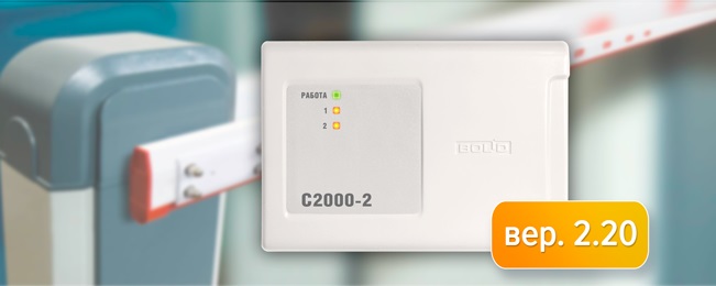
«Доступ под принуждением» — это возможность не вызывая подозрений, дать сигнал охране объекта о том, что действия пользователя (предоставление доступа или снятие с охраны) осуществляются под принуждением злоумышленников. Для этого необходимо заранее подготовить и выдать пользователю специальный идентификатор, предназначенный на этот случай. Чтобы не вызвать подозрений у злоумышленников, для этого идентификатора, как правило, задаются те же права, что и для основного идентификатора пользователя. Но при его предъявлении контроллер дополнительно формирует специальное сообщение «Предъявлен код принуждения» для привлечения внимания охраны объекта. Если используется двойная идентификация (карта + PIN-код), то дополнительная карта не требуется — нужно лишь ввести специальный PIN-код вместо правильного.
Больше возможностей в настройке уровней доступа и шлейфов сигнализации
Расширились возможности настройки уровней доступа пользователей. Во-первых, теперь все, а не часть параметров уровня доступа, задаются отдельно для каждого считывателя контроллера. Во-вторых, количество этих параметров увеличилось. «Двойная идентификация» стала параметром уровня доступа, что позволяет использовать ее для одних групп пользователей и не использовать для других. Функции «Открывающий» ключ и «Закрывающий» ключ также стали параметрами уровня доступа. А поскольку для каждого из считывателей все параметры уровня доступа задаются независимо, то выполняя одну из этих функций на одном считывателе, тот же идентификатор может выполнять совершенно иную функцию на другом считывателе. У шлейфов сигнализации контроллера появились параметры «Автоматическое перевзятие из невзятия» и «Автоматическое перевзятие из тревоги».
Взятие под охрану датчика контроля двери
Теперь цепи подключения датчиков открывания двери (DOOR1, DOOR2) можно объявить шлейфами сигнализации (ШС3, ШС4) и брать их под охрану. Это никак не влияет на основную функцию данных цепей, но позволяет не дублировать датчики открывания двери и не использовать дополнительные входы приемно-контрольных приборов, если эти двери необходимо брать под охрану.
Контроллер доступа “С2000-2″ вер.2.00 на 32 000 пользователей (январь 2014)
Главным отличием нового прибора стал значительно увеличенный объем памяти.
- Теперь в локальном режиме “С2000-2” хранит информацию о 32 768 пользователях, 100 окнах времени, 100 уровнях доступа. В случае отсутствия связи с сетевым контроллером в памяти может быть накоплено до 32 768 событий.
- Срок действия идентификаторов задаётся теперь с точностью до часов и минут, а использование двойной идентификации не уменьшает их максимальное количество.
Кроме того, прибор получил новый вход/выход BUSY и расширенную логику работы шлейфов сигнализации.
- Вход/выход BUSY позволяют синхронизировать работу нескольких контроллеров на аппаратном уровне при организации сложных точек доступа, если во время доступа через считыватель одного контроллера необходимо блокировать доступ через считыватели других контроллеров. В эту же цепь может быть подключён датчик присутствия человека в шлюзе, автомобиля на пандусе или иные цепи, блокирующие начало новой процедуры доступа.
- Добавлен режим прохода «с подтверждением кнопкой» и использования ШС для разрешения считывания (включение/отключение считывателя).
- Добавлена возможность использования ШС для открытия доступа, что позволяет осуществить прямую интеграцию системами пожарной сигнализации на уровне реле (разблокировка дверей).
- Улучшена работа в режиме «Шлюз».
Введена возможность полноценного открытия свободного доступа при использовании электромеханических защёлок, которые открываются коротким импульсом и переходят в состояние «закрыто» только после открытия и последующего закрытия двери. В этом случае, при включении режима «доступ открыт», реле будет включаться кратковременно (на то же время, что и при предоставлении доступа) при каждом закрытии двери и замок будет все время открыт.
Выпущена новая версия 1.15 контроллера С2000-2 (сентябрь 2010)
Компания «Болид» выпустила контроллер С2000-2 вер. 1.15, который в отличие от предыдущей версии 1.11 имеет дополнительные функции:
- Добавлен режим «Доступ разрешен» (санкционированное дежурным предоставление доступа с регистрацией прохода).
- Параметры «Время на проход», «Задержка опускания шлагбаума» и «Время пребывания в шлюзе» сделаны настраиваемыми.
- Поддержан интерфейс Wiegand с большей частотой и меньшей длительностью импульсов.
- Поддержаны события о вкл./выкл. реле.
- Добавлена возможность регистрации проходов в режиме «Доступ открыт».
- Исправлена ошибка протокола ABA TRACKII на втором считывателе.
Источник
forum-bolid.ru
С2000-2 и электромагнитный замок, требуется помощь в подключении.
Доброе время суток.
Если у Вас есть время, прошу помочь, проблема заключается в следующем:
Мне интересно узнать как подключить электромагнитный замок.
На схеме подключений (см. рисунок) замка указано что 1 — +12; 2 — 0; 3 — NO; 4 — C; 5 — NC, причём 4 и 5 объединены (на рисунке, по схеме).
Пожалуйста, объясните новичку как правильно подключить C, NC, NO, и вообще электромагнитный замок, к контроллеру доступа?
Как подключать питание, подключать отдельно (от БП) или от контроллера?
Система выглядит так:
С2000USB C2000-2 Считыватель Электромагнитный замок
Спасибо за ответы, буду пробовать вариант с диодом.
Электромагнитный замок: EGR 600 1203
Откуда узнал, что этот замок с собственной платой.
Модель названа в следующем сообщении.
И так, на всякий случай — http://www.accordtec.ru/site.xp/049057048.html , это к вопросу «с собственной платой»
Из описания «С2000-4» АЦДР.425513.008 РЭ Изм.18 АЦДР.5258-13 от 30.04.201
Если используемый электромагнитный замок (защелка) подключен к тому же источнику питания что и прибор, то его питание должно подводиться от источника отдельным проводом. Рекомендуется питать электромагнитные замки от отдельного источника питания.
Если в конструкции электромагнитного замка не предусмотрена схема подавления импульсов высокого напряжения, возникающего при коммутации, то необходимо на клеммах замка, параллельно его обмотке, устанавливать диод в обратном включении (допустимый ток диода в прямом направлении должен быть не менее 1 А).
Источник
Контроллер замка С2000-2 под 2 выносных считывателя Болид
Контроллер замка С2000-2 предназначен для организации одной или нескольких автономных точек доступа на объект. Точки доступа в этом случае могут быть однонаправленными или двунаправленными, с контролем направления прохода и без него.
Память контроллера способна вмещать 32768 идентификаторов пользователей, 100 временных окон и 100 уровней доступа. С2000-2 используется в составе системы «Орион» или автономно.
Контроллер способен работать в следующих режимах:
- две двери на вход;
- одна дверь на вход/выход;
- турникет;
- шлагбаум;
- шлюз.
Две двери на вход
В этом режиме контроллер управляет двумя независимыми точками доступа. Для прохода в одном направлении необходим идентификатор, а в обратном направлении достаточно нажать кнопку «Выход». Каждый считыватель может быть настроен для двойной идентификации, для доступа с подтверждением и прохода по правилу двух или более лиц. Оба считывателя работают при этом независимо друг от друга. Это значит, что при свободном доступе на одном считывателе, второй будет находиться в дежурном режиме, пока не получит необходимую команду.
Одна дверь на вход/выход
Режим применяется при проходе через одну дверь, имеющую одно запорное устройство и один датчик доступа. Если необходимо пройти туда и обратно, требуется предъявить идентификатор пользователя. В данном режиме может применяться правило Antipassback — запрет повторного прохода, доступ с подтверждением или по правилу двух и более лиц, двойная идентификация. Считыватели контроллера работают синхронно — когда команда подаётся на один считыватель, второй автоматически переходит в тот же режим.
Турникет
В этом режиме проход осуществляется через электромеханический турникет. В выносном блоке турникета находятся две цепи управления для каждого направления прохода. В обоих направлениях необходимо предъявлять идентификаторы пользователей. Оператор может дистанционно открывать доступ с помощью кнопки «Выход». В данном режиме можно применять правило Antipassback, двойная идентификация, доступ с подтверждением или по правилу двух и более лиц. Считыватели контроллера работают независимо друг от друга.
Шлагбаум
В данном режиме первое реле контроллера управляет подъёмом шлагбаума, второе реле — опусканием. Проезд разрешается в обоих направлениях при предоставлении идентификатора пользователя. Кнопки «Въезд» и «Выезд» используются для ручного управления шлагбаумом. Благодаря датчикам, автомобиль защищён от опускания шлагбаума во время проезда. Датчики проезда размещаются на шлагбауме с двух сторон для того, чтобы транспорт, находящийся под ним, заставлял срабатывать хотя бы один датчик. В этом режиме работы может применяться правило Antipassback, двойная идентификация, доступ с подтверждением или по правилу двух и более лиц. Считыватели контроллера работают синхронно.
В этом режиме контроллер управляет доступом через шлюз, представляющий собой две двери с замкнутым пространством посередине, которые не могут быт открыты одновременно. Вне шлюза на входе устанавливаются два считывателя. На посту охраны имеются две кнопки «Выход» для прохода человека в шлюз без предъявления идентификатора, две кнопки «Подтверждение», чтобы выпустить человека из шлюза, и кнопка «Запрет» — для отказа в доступе. Первая дверь (вход в шлюз) открывается после предъявления идентификатора. Проход через вторую дверь доступен либо автоматически после закрытия первой двери, либо после нажатия охранником кнопки «Подтверждение». В случае, когда поста охраны нет, кнопка «Подтверждение» всё равно подключается, чтобы человек мог выйти через ту дверь, в которую зашёл, если он передумал или задержался внутри больше отведённого времени. Допустимое время пребывания человека в шлюзе задаётся параметром «Время на подтверждение доступа». В режиме работы «Шлюз» может применяться правило Antipassback, двойная идентификация, доступ с подтверждением. Считыватели контроллера работают синхронно.
Источник