-
Contents
-
Table of Contents
-
Bookmarks
Quick Links
SAILOR 500 FleetBroadband
Dual Antenna Solution
Installation and user manual
Related Manuals for COBHAM SAILOR 500 FleetBroadband
Summary of Contents for COBHAM SAILOR 500 FleetBroadband
-
Page 1
SAILOR 500 FleetBroadband Dual Antenna Solution Installation and user manual… -
Page 3
SAILOR 500 FleetBroadband Dual Antenna Solution Installation and user manual Document number: 98-138669-B Release date: March 20, 2015… -
Page 4
In the event of any discrepancies, the English version shall be the governing text. Thrane & Thrane A/S is trading as Cobham SATCOM. Copyright © 2015 Thrane & Thrane A/S. All rights reserved. -
Page 5
Safety summary The following general safety precautions must be observed during all phases of operation, service and repair of this equipment. Failure to comply with these precautions or with specific warnings elsewhere in this manual violates safety standards of design, manufacture and intended use of the equipment. -
Page 6
Personnel installing or servicing the system must be properly trained and authorised by Cobham SATCOM. It is important that you observe all safety requirements listed in the beginning of this manual, and install the system according to the guidelines in this manual. -
Page 7: Table Of Contents
To install the Dual Antenna Control Unit ……..8 Outline drawing, DACU …………..12 Outline drawing, cabinet for rack mount ……. 13 To install the SAILOR 500 FleetBroadband systems ..15 Chapter 3 Configuration To configure the dual antenna solution ……… 17 To configure the slave terminal ……….
-
Page 8
Table of contents NMEA0183 input (X3) …………..36 LAN interface (X6) …………….39 To ground the Dual Antenna Control Unit ……40 Cable requirements …………….40 Chapter 5 Service To update software …………….41 Status signalling ……………… 44 To return units for repair …………..46 To repack for shipment ………….. -
Page 9: Purpose Of The Sailor 500 Fleetbroadband Dual Antenna Solution
Purpose of the SAILOR 500 FleetBroadband Dual Antenna Solution When your SAILOR 500 FleetBroadband antenna cannot obtain full line of sight to the satellite, e.g. because of blocking objects on board the ship, you can use a dual antenna solution. The purpose of the dual antenna solution is to obtain full line of sight with a combination of two SAILOR 500 FleetBroadband systems.
-
Page 10: Units In The Dual Antenna Solution
Units in the dual antenna solution A dual antenna solution consists of the following units: • Two SAILOR 500 FleetBroadband terminals (master and slave) • Two SAILOR 500 FleetBroadband antennas (A and B) • An IP Handset (optional — included with the SAILOR 500 FleetBroadband terminals) •…
-
Page 11
IP Handset (other local numbers) Any version SAILOR 500 FleetBroadband terminals For details on the SAILOR 500 FleetBroadband terminals, see the SAILOR FleetBroadband manuals [1] and [2]. Master/slave configuration The master terminal controls the system and connects to user equipment. -
Page 12
Chapter 1: Introduction SAILOR 500 FleetBroadband antennas For details on the SAILOR 500 FleetBroadband antennas, see the SAILOR FleetBroadband manuals [1] and [2]. Minimum antenna version Early versions of the FleetBroadband antennas will not work Important with the dual antenna solution. Check the serial number label on your antennas for the information below. -
Page 13
Chapter 1: Introduction IP Handset Functions of the IP Handset In addition to the general functions of the IP Handset, the master handset (with local number 0501) can be used to check the status of the dual antenna system. If manual switchover is selected in the web interface, you can also select which antenna is to be active. -
Page 14
Chapter 1: Introduction Units in the dual antenna solution… -
Page 15: Installation
Chapter 2 Installation This chapter describes how to unpack, store and install the Dual Antenna Control Unit and how to install the SAILOR 500 FleetBroadband Dual Antenna Solution. It contains the following sections: • To unpack the Dual Antenna Control Unit •…
-
Page 16: To Install The Dual Antenna Control Unit
Chapter 2: Installation Warning! To avoid electric shock, do not apply power to the system if there is any sign of shipping damage to any part of the front or rear panel or the outer cover. Read the safety summary at the front of this manual before installing or operating the system.
-
Page 17
Chapter 2: Installation To mount the Dual Antenna Control Unit The Dual Antenna Control Unit can be mounted on a flat surface, e.g. on a bulkhead, or in a cabinet for rack-mounting. Distance between units: When installing the DACU, keep in mind that the DACU and the FleetBroadband terminals must be placed close enough to each other to comply with the maximum cable lengths (100 m for Ethernet). -
Page 18
Chapter 2: Installation 2. Tighten the screws. 3. Connect all cables as described in Connecting cables on page 31 and fasten the cables to the cable relief with cable strips. 4. When all cables are installed, mount the cover for the spring-loaded terminals. -
Page 19
Chapter 2: Installation To mount the unit in a rack The Dual Antenna Control Unit is available in a cabinet for rack-mounting. 1. Slide the DACU with cabinet into a 2U space in a 19” rack. 2. Mount two screws in each side through the holes in the front and fasten the screws to the rack. -
Page 20: Outline Drawing, Dacu
Chapter 2: Installation Outline drawing, DACU Dimensions are in mm. Outline drawing, DACU…
-
Page 21: Outline Drawing, Cabinet For Rack Mount
Chapter 2: Installation Outline drawing, cabinet for rack mount Bottom and front view Dimensions are in mm. Outline drawing, cabinet for rack mount…
-
Page 22
Chapter 2: Installation Top and side view Dimensions are in mm. Outline drawing, cabinet for rack mount… -
Page 23: To Install The Sailor 500 Fleetbroadband Systems
The following antennas can be used with the dual antenna solution: P/N 403052C-THR-001 or 403052C-NEU-001, all revisions. P/N 403052C: Antennas with • minimum Rev. B.03 and • minimum S/N 80519208 To install the SAILOR 500 FleetBroadband systems…
-
Page 24
Dual Antenna Control Unit. SIM card The SAILOR 500 FleetBroadband Dual Antenna Solution is one system that uses one SIM card, installed in the master terminal. If a SIM card is installed in the slave terminal, it is not used as long as the system is configured to be a dual antenna solution. -
Page 25: Configuration
Chapter 3 Configuration To configure the dual antenna solution To use your SAILOR 500 FleetBroadband Dual Antenna Solution you must go through the following configuration steps with the built-in web interface of the SAILOR 500 FleetBroadband terminals: • To configure the slave terminal •…
-
Page 26
Chapter 3: Configuration 5. Enter the administrator user name and password (default: user name: admin and default password: 1234). 6. From the left navigation pane, select Dual antenna. 7. Select Slave. 8. At Local IP address, type in a new IP address different from the master, but in the same range (192.168.0.—), e.g. -
Page 27: To Configure The Master Terminal
Chapter 3: Configuration To configure the master terminal To set the terminal to be master The SIM card must be present in the master terminal. Note For details on how to insert the SIM card, see the SAILOR 500 FleetBroadband Installation manual [2]. 1.
-
Page 28: To Check The Dual Antenna Function
The Power and Antenna indicators must be green. The Terminal indicator must be green or flashing green. For details, see the SAILOR 500 FleetBroadband User manual [1]. 3. If possible, check the light indicators on the DACU. They must both be green.
-
Page 29
Chapter 3: Configuration Check with web interface To verify that the system works as a dual antenna solution, do as follows: 1. On the master terminal, access the web interface and select HELPDESK > Extended status. 2. Under Dual antenna check that the Status field shows Operational. If Manual switchover is selected, the Status field shows Note Manual instead of Operational. -
Page 30
Chapter 3: Configuration Check with IP Handset Only the master handset (IP Handset with number 0501) can be used to access the dual antenna status and settings. For general information on the IP Handset, see the user manual [3]. The IP handset can only show dual antenna status and settings if Note connected to a functional dual antenna solution. -
Page 31: To Select Antenna Switchover
Chapter 3: Configuration To select antenna switchover By default, the system automatically switches antenna if the active antenna moves into a blocking zone. However, you can choose to manually select one of the antennas. • The antenna connected to the master terminal is called A. •…
-
Page 32
Chapter 3: Configuration The system will now only use the selected antenna. In the web interface under HELPDESK > Extended status you can check that the correct antenna is active. To select the active antenna from the IP Handset If Antenna switchover is set to Manual in the web interface, you can use the master IP Handset (no.0501) to change which antenna is to be active. -
Page 33: To Configure Blocking Zones
Visibility affects the Quality of Service during the antenna switch. The SAILOR 500 FleetBroadband Dual Antenna Solution can automatically switch to the other antenna if the active antenna moves into a blocking zone. For the system to work properly, it is important that you Important identify and configure the blocking zones for the ship.
-
Page 34
Chapter 3: Configuration Margin for blocking zones In the example below, extra margin is added to the blocking zones for the two antennas. When the Antenna A passes from free line of sight to e.g. the 52° limit configured in the system, the system switches to Antenna B before the actual blocking (at 45°) occurs. -
Page 35
Chapter 3: Configuration When the active Antenna A enters the configured blocking zone at 52°, it will not switch over to Antenna B, because B is also configured to be in a blocking zone, though it actually has line of sight to the satellite. Always avoid blind spots if possible! Important To configure blocking zones… -
Page 36
Chapter 3: Configuration These blocking zones are for the antenna connected to the Note terminal, i.e. if you are configuring the master terminal, the blocking zones are for the antenna connected to the master terminal (called antenna A). 3. Select Active to enable the blocking zone. 4. -
Page 37
Chapter 3: Configuration To see information on blind spots When both terminals are configured and the system is operational, the master terminal can show whether or not there are configured blind spots (areas where both antennas are configured to be blocked). To check for blind spots, access the web interface of the master terminal and select Blocking zones. -
Page 38
Chapter 3: Configuration To configure blocking zones… -
Page 39: Connecting Cables
This chapter provides a description of the connectors on the Dual Antenna Control Unit and gives guidelines to cabling of the SAILOR 500 FleetBroadband Dual Antenna Solution. It has the following sections: • To connect the SAILOR 500 FleetBroadband Dual Antenna Solution •…
-
Page 40: To Connect The Sailor 500 Fleetbroadband Dual Antenna Solution
LAN 2 Lower priority signalling and ship heading information The picture below shows the location of the LAN connectors in the connector panel of a SAILOR 500 FleetBroadband terminal. LAN interface To connect the SAILOR 500 FleetBroadband Dual Antenna Solution…
-
Page 41
Power (X2) on page 35. 6. When all units in the system are connected, verify the function of the system as described in To check the dual antenna function on page 20. To connect the SAILOR 500 FleetBroadband Dual Antenna Solution… -
Page 42: Dacu Connector Overview
Chapter 4: Connecting cables DACU Connector overview The drawing below shows the connectors on the Dual Antenna Control Unit. X6 is a standard Ethernet connector (RJ-45), X2 and X3 are spring-loaded terminals. Only X2, X3 and X6 are used. Note DACU Connector overview…
-
Page 43: Power (X2)
Chapter 4: Connecting cables Power (X2) X2 is used for connecting power (12-24 VDC) to the DACU. For specifications for the power input, see Specifications on page 49. Refer to the drawing and pinout table below for location and pin-out. The table below shows the pin assignment of X2.
-
Page 44: Nmea0183 Input (X3)
Chapter 4: Connecting cables NMEA0183 input (X3) Overview There is one NMEA0183/ IEC 61162-1 input on the DACU. This input is used to connect the NMEA0183 ship heading true (HDT) information from the ship to the DACU. The baud rate must be 4800 Bd. For specifications on the NMEA0183 interface, see NMEA input on page 49.
-
Page 45
Chapter 4: Connecting cables Pin-out The table below shows the pin assignment of X3. Pin no. Pin function on X3 NMEA0183- (A) NMEA0183+ (B) Field Signal GND (C) Do not connect Do not connect Digital GND Differential connection For a differential connection, connect your cable as follows: Pin no. -
Page 46
Chapter 4: Connecting cables Single-ended connection This connection type is not recommended, use only in Note installations with short cabling. For a single-ended connection, connect your cable as follows: Pin no. Pin function on X3 Single-ended connection NMEA0183- (A) NMEA0183- (A) NMEA0183+ (B) GND (Connect to Pin 3) Field Signal GND (C) -
Page 47: Lan Interface (X6)
Chapter 4: Connecting cables LAN interface (X6) Overview There is one Ethernet (10/100 MB) connector on the Dual Antenna Control Unit. This interface is used to connect the DACU to one of the FleetBroadband terminals in the dual antenna solution. We recommend connecting to the slave unit, in order to reserve the free LAN connectors for user interfaces on the master unit.
-
Page 48: To Ground The Dual Antenna Control Unit
Chapter 4: Connecting cables To ground the Dual Antenna Control Unit The base plate of the Dual Antenna Control Unit must be connected to ship ground in one of two ways: • Mount the Dual Antenna Control Unit on a conducting surface connected to ship ground, or •…
-
Page 49: Chapter 5 Service
To update software SAILOR 500 FleetBroadband terminals The software for the SAILOR 500 FleetBroadband terminals can be updated using the ThraneLINK Management Application (TMA) described below, or using the built-in web interface of the terminals. See the user manual for the SAILOR 500 FleetBroadband terminals [1] for details.
-
Page 50
Chapter 5: Service 3. Locate the new software image for the Dual Antenna Control Unit (.tiif file). 4. Download the .tiif file to a USB memory stick or to a folder on your PC. To update the Dual Antenna Control Unit software To update the Dual Antenna Control Unit software, do as follows: 1. -
Page 51
Chapter 5: Service screen and on the Dual Antenna Control Unit page at the bottom, where the icon for software update flashes. 5. Click the icon Software update. 6. Click the button Update and wait for the update procedure to finish. The software is now updated and the Dual Antenna Control Unit automatically restarts with the new software. -
Page 52: Status Signalling
Chapter 5: Service Status signalling Light indicators The Dual Antenna Control Unit has two light indicators for signalling status and errors/warnings. The indicators are not visible in the rack version. Note Power Status The following sections show the function of each light indicator. Status signalling…
-
Page 53
Chapter 5: Service Light indicator functions Power indicator Behavior Meaning Steady green Dual Antenna Control Unit is on. Dual Antenna Control Unit is off. Status indicator Behavior Meaning Steady green Dual Antenna Control Unit is OK. Steady red Critical error. Dual Antenna Control Unit is off Should the system fail, you may see a warning message in the web interface in the FleetBroadband terminals. -
Page 54: To Return Units For Repair
Your dealer, installer or Cobham SATCOM partner will assist you whether the need is user training, technical support, arranging on-site repair or sending the product for repair. Your dealer, installer or Cobham SATCOM partner will also take care of any warranty issue. To repack for shipment The shipping carton has been carefully designed to protect the Dual Antenna Control Unit and its accessories during shipment.
-
Page 55: Part Numbers
SAILOR 500 FleetBroadband DACU in 19” Rack 403748A-00510 SAILOR 500 FleetBroadband system For information on the SAILOR 500 FleetBroadband system, see the user manual for the SAILOR 500 FleetBroadband system [1]. You need two SAILOR 500 FleetBroadband systems in the Note SAILOR 500 FleetBroadband Dual Antenna Solution.
-
Page 56
Chapter 5: Service Part numbers… -
Page 57: General Specifications For The Dacu
Specifications This appendix only contains the specifications for the SAILOR FleetBroadband Dual Antenna Control Unit. For specifications for the SAILOR 500 FleetBroadband system, see the installation manual for the SAILOR 500/250 FleetBroadband system [2]. General specifications for the DACU Item…
-
Page 58
Appendix A: Specifications Item Specifications Compass safe 20 cm distance Dimensions Stand-alone 239 mm x 174 mm x 52 mm (9.4” x 6.9” x 2”) DACU In 19” Rack 483 mm x 388 mm x 88 mm (19” x 15.3” x 3.5”), including cabinet (2U) cable relief Weight… -
Page 59: Glossary
Glossary Glossary DACU Dual Antenna Control Unit. Actual vessel Heading in Degrees True. IMSO International Mobile Satellite Organisation. An intergovernmental organisation that oversees certain public satellite safety and security communication services provided via the Inmarsat satellites. Ingress Protection. An international classification system for the sealing effectiveness of enclosures of electrical equipment against the intrusion into the equipment of foreign bodies (i.e.
-
Page 60
Glossary… -
Page 61: Index
Index Index differential connection NMEA 0183, 37 active antenna dimensions, 50 select manually with IP Handset, 24 cabinet for rack mount, 13 select manually with web interface, DACU, 12 document number administrator this manual, i password for web interface, 17 dual antenna function antenna version, 4 verifying, 20…
-
Page 62
Index items included in delivery, 8 part numbers, 47 password web interface, administrator, 17 LAN connector, 39 Power connector, 35 LED signalling, 44 rack mounting, 11 manual repacking for shipment, 46 document number, i returning units, 46 manual selection of active antenna IP Handset, 24 web interface, 23 master terminal… -
Page 63
Index unpacking, 7 updating software, 41 verifying dual antenna function, 20 version of antennas, 4 version of software, 3 warranty, 46 web interface configuring blocking zones, 25 configuring master terminal, 19 configuring slave terminal, 17 select active antenna, 23 view dual antenna status, 21… -
Page 64
98-138669-B www.cobham.com/satcom…
Inmarsat в России > Оборудование > Морское спутниковое оборудование > FBB SAILOR 500

Sailor FleetBroadBand 500 — судовая станция, работающая в сети Inmarsat FleetBroadBand, является топовым решением в своем классе. Терминал поддерживает подключение через порт ISDN ПК или мини-АТС с подключением до 16 IP-телефонов, что является качественным отличием от младших устройств FleetBroadBand 150 и 250. Также отличительной особенностью является то, что возможен одновременный доступ как к услугам голосовой связи, так и к сервису передачи данных.
Ключевые особенности:
— Фоновое IP-соединение для электронной почты и интернет/интранет, доступ с безопасными возможностями VPN.
— Потоковая передача данных (качество обслуживания для данных сессий и приложений, требующих выделенную полосу пропускания от 8, 16, 32, 64, 128 или 256 кбит/с).
— ISDN 64 кбит/с.
— Одновременная передача данных и голоса.
— Удалённый доступ к терминалу как на борту, так и с берега.
— Возможность организации внутренних звонков – до 16 IP-телефонов, которыми может управлять непосредственно пользователь, имеющий свой собственный добавочный номер.
SAILOR 500 FleetBroadband — судовая станция, призванная обеспечить вас всеми современными услугами связи: голосовой связью (в том числе с высоким качеством стандарта ISDN 3.1kHz Audio), передачей факса, данных, доступом в интернет с гарантированной скоростью до 256 кбитс. Имеются функции вэб сервера с возможностью удаленного управления, NAT роутера, DHCP сервера, SIP сервера. SAILOR 500 может управлять 16 IP-телефонами при подключении к терминалу судовой мини-АТС. На каждый IP-трубку можно звонить индивидуально с берега, а также локально с судна.
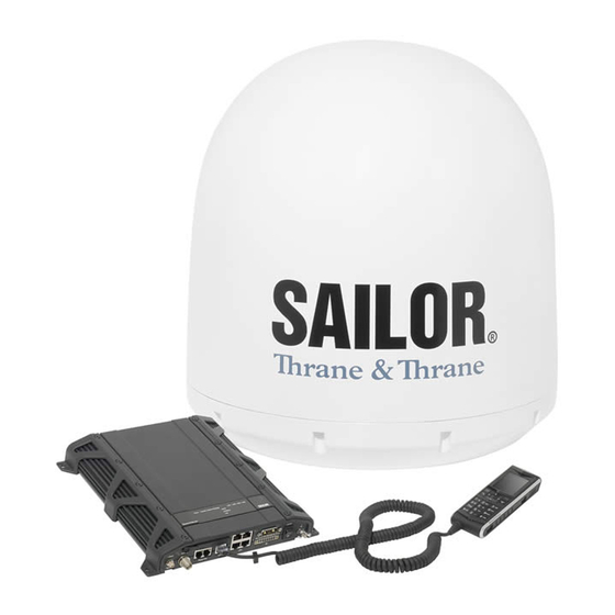
Комплектация:
— SAILOR 500 Антенный блок
— SAILOR FleetBroadband блок процессора
— SAILOR IP-телефон (проводной)
— Блок питания (28V/25ADC)
— 30-метровый антенный кабель (RG-223), N & TNC
— руководство пользователя по установке
| Частотный диапазон: | Приём: 1525.0 – 1559.0 мГц Передача: 1626.5 – 1660.5 мГц Ширина канала: приём – 10.5 -189 кГц, передача – 21 – 189 кГц |
| Рекомендованный антенный кабель: | Потери в кабеле (макс/мин): 20 дБ на частоте 1,62 ГГц и 1,0 Ω DC сопротивление контура 3 дБ на расстоянии 36-4 дБ при 54 мГц |
| Голос: | 4 кбит/c AMBE +2 |
| ISDN голос: | 3.1 кГц Аудио |
| ISDN: | 64 кбит/с UDI 56 кбит/с RDI |
| Скорость в канале: | до 432 кбит/с |
| Потоковые данные по IP: | 8, 16, 32, 64, 128, 256 бит/с |
| SMS: | до 160 символов |
| Антенный коннектор: | Антенна – 50 Ω N, female Терминал – TNC-гнездо, female |
| Интерфейсы терминала: | Кнопка вкл/выкл. питания Разъём питания с управлением удалённого включения/выключения и механизмом фиксации вилки 4 10/100Mbit Ethernet LAN с PoE 1 Euro ISDN Слот для SIM-карты Заводская кнопка RESET 2 назависимых 2-хпроводный телефонных разъёма RJ-11 5х I/O L-band-выход LED индикатор |
| Питание: | Входной диапазон постоянного тока: 10-32 В Питание (макс.), включая антенну и PoE-вход: 120 Вт, 10-32 В |
| Диапазон рабочих температур: | -25°C…+55°C |
| Температура хранения: | -40°C…+85°C |
| Диапазон температр, при котором: устройство может быть включено, но не функционирует | -40°C…+80°C |
| Наличие функции автоматического контроля температуры, постепенно отключающей работу системы: | |
| Рабочая относительная влажность: | 95% без образования конденсата, при +40°C |
| Защита корпуса антенны: | IPX6 |
| Относительная влажность для антенны: | в соответствии со стандартом EN60 945 |
| Защита корпуса терминала: | соответствует стандарту IP31 |
| Обледенение: | макс. 25 мм |
| Функции телефона: | Телефонная книга Индикатор сообщения Запрет вызовов Учёт трафика Местные номера До 16 телефонов с местными номерами |
| Функции роутера: | Web-сервер Встроенный NAT маршрутизатор DHCP сервер Управление сетью SIP-сервер 11 PDP контекст |
| Размеры: | Терминал: 264.5 х 273 х 42.5 мм Антенна: 797.5 x Ø 687 мм |
| Вес: | Терминал: 2.5 кг Антенна: 23 кг |
Оборудование
Спутниковые телефоны
- IsatPhone2
- IsatPhone Pro
Портативные спутниковые терминалы
- IsatHub
- Wideye Sabre 1
- BGAN Explorer 300
- BGAN Explorer 500
- BGAN Explorer 510
- BGAN Explorer 710
- Hughes 9201
- Hughes 9202
Морское спутниковое оборудование
- SAILOR Fleet One
- FBB SAILOR 150
- FBB SAILOR 250
- FBB SAILOR 500
- Sailor 6120 Mini-C SSAS
- TERRA 400
- TERRA 800
- TranSAT
- EXPLORER 5075GX
- BGAN Explorer 325
- BGAN Explorer 527
- BGAN Explorer 727
- AVIATOR 200
- AVIATOR 300
- AVIATOR 350
- AVIATOR 700
- Архив новостей
Комплекты фиксированной спутниковой связи
Авто-комплекты
Авиационное спутниковое оборудование
Новости
2018-12-06 — Изменения в покрытии Inmarsat-C
В связи с запланированной миграцией спутника AORE с 15,5 W (спутник I-3 F2) до 54 W (спутник I-3 F5), который должен состояться 30 октября 2018 года в 11:00 UTC, произойдут изменения в покрытии Инмарсат С по Гренландскому морю между Гренландией и Норвегией.
Подробнее
2018-06-08 — Bysky — мобильное приложение для бесплатного и безопасного обмена сообщениями с различными спутниковыми устройствами
Подробнее
2018-03-28 — Разъяснение о процедуре признания стандарта Инмарсат в качестве услуги ГМССБ
План по модернизации ГМССБ был предложен Подкомитетом по навигации, радиосвязи, поиску и спасению в марте 2017 года. Этот план предлагает разработку ряда поправок к конценции СОЛАС, для их рассмотрения и одобрения в 2021 году, и вступления в силу в 2024 году.
Подробнее
Партнеры


-
Page 1
SAILOR 500/250 FleetBroadband Including 19” Rack Version Installation manual… -
Page 3
SAILOR 500 FleetBroadband SAILOR 250 FleetBroadband Including 19″ Rack Version Installation manual Document number: 98-125646-G Release date: November 1, 2013… -
Page 4
Thrane & Thrane A/S is not responsible for the content or accuracy of any translations or reproductions, in whole or in part, of this manual from any other source. Thrane & Thrane A/S is trading as Cobham SATCOM. Copyright © 2013 Thrane & Thrane A/S. All rights reserved. Trademark acknowledgements •… -
Page 5: Safety Summary
0.4 m from the antenna panel. Refer to the drawing on the next page. Pour une antenne SAILOR 500 FleetBroadband, la distance de sécurité minimale avec le panneau de l’antenne sur l’axe focal est de 1.3 m, sur la base d’un niveau de radiation émis de 10 W/m…
-
Page 6
Service User access to the interior of the terminal is prohibited. Only a technician authorized by Cobham SATCOM may perform service — failure to comply with this rule will void the warranty. Access to the interior of the antenna is allowed, but only for replacement of certain modules — as described in the Installation manual. -
Page 7
Do not service or adjust alone Do not attempt internal service or adjustments unless another person, capable of rendering first aid resuscitation, is present. Grounding, cables and connections To minimize shock hazard, the equipment chassis and cabinet must be connected to an electrical ground. The terminal must be grounded to the ship. -
Page 8: About The Manual
About the manual Intended readers This is an installation manual for the SAILOR 500 FleetBroadband and the SAILOR 250 FleetBroadband systems. The manual is intended for installers of the system and service personnel. Personnel installing or servicing the system must be properly trained and authorized by Cobham SATCOM. It is important that you observe all safety requirements listed in the beginning of this manual, and install the system according to the guidelines in this manual.
-
Page 9
Related documents The below list shows the documents related to this manual and to the SAILOR 500 FleetBroadband and SAILOR 250 FleetBroadband systems. Document Title and description number SAILOR 500/250 FleetBroadband Including 19″ 98-125645 Rack Version, User Manual Explains how to set up and use the SAILOR FleetBroadband systems. -
Page 10
Typography In this manual, typography is used as indicated below: Bold is used for the following purposes: • To emphasize words. Example: “Do not touch the antenna”. • To indicate what the user should select in the user interface. Example: “Select SETTINGS > LAN”. Italic is used to emphasize the paragraph title in cross-references. -
Page 11: Table Of Contents
Chapter 1 System units 1.1 Introduction ……………….1 1.2 SAILOR FleetBroadband terminal ……….1 1.3 SAILOR 500 FleetBroadband antenna ……..3 1.4 SAILOR 250 FleetBroadband antenna ……4 1.5 Thrane IP Handset & Cradle ……….5 Chapter 2 Installing the system 2.1 Unpacking ………………..7…
-
Page 12
Table of contents 4.3 DC power input …………… 61 4.4 Ground stud …………….63 4.5 19” rack version only: Terminal block ……64 4.6 Analogue Phone/Fax interface ……..65 4.7 ISDN interface …………….. 66 4.8 LAN interface …………….68 4.9 Discrete I/O interface …………71 4.10 L-Band interface ………….. -
Page 13
Table of contents Appendix B Technical specifications B.1 Overview …………………121 B.2 SAILOR 500 FleetBroadband antenna …… 122 B.3 SAILOR 250 FleetBroadband antenna ……131 B.4 Minimum distance to transmitters ……135 B.5 SAILOR FleetBroadband terminal ……..136 Appendix C Grounding and RF protection C.1 Why is grounding required? -
Page 14
Table of contents… -
Page 15
Min. distance, radar (X-band) and FleetBroadband antenna ..12 Table 5: Min. distance, radar (S-band) and FleetBroadband antenna ..12 Table 6: Antenna mast length SAILOR 500 FleetBroadband……21 Table 7: Antenna mast length SAILOR 250 FleetBroadband……22 Table 8: Recommended antenna cable types and max. cable lengths..24… -
Page 16
Table 22: LED indicator functions: LAN PoE…………115 Appendix A Part numbers Table 23: Part numbers, SAILOR 500 FleetBroadband system ….119 Table 24: Part numbers, SAILOR 250 FleetBroadband system ….119 Table 25: Part numbers, Thrane IP Handset & Cradle, Wired……. 120… -
Page 17: System Units
The basic system consists of three units: The terminal, the antenna and the IP handset with cradle. There are two different types of antennas, depending on whether you have a SAILOR 500 FleetBroadband system or a SAILOR 250 FleetBroadband system. 1.2 SAILOR FleetBroadband terminal The terminal is the central unit in the system.
-
Page 18
Chapter 1: System units Below is the terminal for wall or desktop installation. Below is the 19” rack version of the terminal. The terminal supplies 18-29 V DC to the antenna through a single coaxial cable. The DC input for the terminal is designed for both 24 V DC and 12 V DC power supply. -
Page 19: Sailor 500 Fleetbroadband Antenna
Chapter 1: System units 1.3 SAILOR 500 FleetBroadband antenna The SAILOR 500 FleetBroadband antenna is a mechanical tracking antenna, consisting of a stabilized antenna with RF-unit, antenna control unit and GPS antenna. The antenna is dedicated to the Inmarsat BGAN (Broadband Global Area Network) system.
-
Page 20: Sailor 250 Fleetbroadband Antenna
Chapter 1: System units 1.4 SAILOR 250 FleetBroadband antenna The SAILOR 250 FleetBroadband antenna is a BGAN mechanical tracking antenna. All communication between the antenna and terminal passes through a single coaxial cable. The antenna unit is protected by a thermo- plastic radome.
-
Page 21: Thrane Ip Handset & Cradle
Chapter 1: System units 1.5 Thrane IP Handset & Cradle 1.5.1 Thrane IP Handset Besides the normal functions of an IP handset, the Thrane IP handset also provides a user interface for the SAILOR FleetBroadband system. The IP handset connects to the LAN interface of the terminal, and is power supplied with Power over Ethernet (PoE) through the LAN interface.
-
Page 22
Chapter 1: System units Thrane IP Handset & Cradle… -
Page 23: Installing The System
• TT-3738A SAILOR FleetBroadband terminal or TT-3738A-T19 SAILOR FleetBroadband 19″ Rack Terminal • TT-3052A/B/C SAILOR 500 FleetBroadband antenna or TT-3050A SAILOR 250 FleetBroadband antenna • TT-3670A Thrane IP Handset & Cradle, wired • Basic cable support kit including an I/O connector, or for 19”…
-
Page 24: Placing The Antenna
2.2.1 Obstructions The antenna rotates 360° and down to –25° for the SAILOR 500 FleetBroadband and -60° for the SAILOR 250 FleetBroadband in pitch and roll, to allow for continuous pointing even in heavy sea conditions. Any objects within this field can cause signal degradation.
-
Page 25: Table 3: Safety Distance Versus Radiation Level
Chapter 2: Installing the system 2.2.2 Radiation hazard The SAILOR 500 FleetBroadband antenna radiates up to 22 dBW EIRP. This translates to a minimum safety distance of 1.3 m from the antenna while it is transmitting, based on a radiation level of 10 mW/cm The SAILOR 250 FleetBroadband antenna radiates 16.1 dBW EIRP.
-
Page 26
Chapter 2: Installing the system 2.2.3 Interference Overview The antenna must be mounted as far away as possible from the ship’s radar and high power radio transmitters (including other Inmarsat based systems), because they may compromise the antenna performance. RF emission from radars might actually damage the antenna. -
Page 27
Chapter 2: Installing the system Radar It is difficult to give exact guidelines for the minimum distance between a radar and the antenna because radar power, radiation pattern, frequency and pulse length/shape vary from radar to radar. Further, the antenna is typically placed in the near field of the radar antenna and reflections from masts, decks and other items in the vicinity of the radar are different from ship to ship. -
Page 28: Table 4: Min. Distance, Radar (X-Band) And Fleetbroadband Antenna
4.0 m 2.0 m Table 4: Min. distance, radar (X-band) and FleetBroadband antenna S-band (~ 10 cm / 3 GHz) damage distance SAILOR 500 FleetBroadband SAILOR 250 FleetBroadband Radar d min. at 15° d min. at 60° d min. at 30°…
-
Page 29
Chapter 2: Installing the system The separation distance for C-band (4-8 GHz) radars should generally be the same as for X-band radars. Radar interference Even at distances greater than “d min.” in the previous section the radar might still be able to degrade the performance of the SAILOR FleetBroadband system. -
Page 30
Chapter 2: Installing the system GPS receivers Good quality GPS receivers will work properly very close to the antenna — typically down to one meter outside the main beam, and down to a few meters inside the main beam. However, simple GPS receivers with poor frequency discrimination could be affected at longer range (typically 10 m). -
Page 31
• 16 kg for TT-3052A, 19 kg for TT-3052B or 23 kg for TT-3052C (+ the weight of the mast flange) for the SAILOR 500 FleetBroadband antenna • 3.9 kg (+ 1.1 kg for the mast mount kit) for the SAILOR 250 FleetBroadband antenna. -
Page 32
SAILOR 500 FleetBroadband antenna mast flange for TT- 3052A/B 1. The top of the SAILOR 500 FleetBroadband antenna mast for TT- 3052A/B should be fitted with a flange with holes matching the bushings in the radome. The flange thickness must be at least 10 mm. -
Page 33
Chapter 2: Installing the system SAILOR 500 FleetBroadband antenna mast flange for TT-3052C 1. The top of the SAILOR 500 FleetBroadban d antenna mast for TT-3052C should be fitted with a flange with holes matching the bushings in the radome. The flange thickness must be at least 10 mm. -
Page 34
SAILOR 250 FleetBroadband antenna mast mounting Mast mount kit: The top of the SAILOR 250 FleetBroadband antenna mast should be fitted with the dedicated mounting kit available from Cobham SATCOM. Assemble the mast mount kit according to the assembly instruction included with the kit. -
Page 35
Chapter 2: Installing the system Mast length and diameter The placement of the antenna must ensure a rigid structural connection to the hull or structure of the ship. Parts of the ship with heavy resonant vibrations are not suitable places for the antenna. A small platform or short mast shall provide rigid support for the antenna fastening bolts and a rigid interface to the ship. -
Page 36
SAILOR 500 FleetBroadband antenna mast length for TT-3052A/B/C Table 6 on page 21 shows the values for a SAILOR 500 FleetBroadband antenna mast without stays or wires. Note that these values are only guidelines — always consider the environment and characteristics of the ship before deciding on the mast dimensions. -
Page 37: Table 6: Antenna Mast Length Sailor 500 Fleetbroadband
< 2.7 105.4 136.7 Table 6: Antenna mast length SAILOR 500 FleetBroadband a. TT-5032A/B: The diameter of the circle where the bolts are to be mounted on the antenna is Ø183.8. Since the mast diameter is larger, you must use a tapered end on the mast, or find other means of accessing the mounting bushings.
-
Page 38: Table 7: Antenna Mast Length Sailor 250 Fleetbroadband
Chapter 2: Installing the system SAILOR 250 FleetBroadband antenna mast length The below table shows the values for a SAILOR 250 FleetBroadband antenna mast without stays or wires. Note that these values are only guidelines — always consider the environment and characteristics of the ship before deciding on the mast dimensions.
-
Page 39: Installing The Antenna
Chapter 2: Installing the system 2.3 Installing the antenna 2.3.1 Antenna grounding You may ground the antenna using the mounting bolts. If the antenna cannot or should not be electrically connected directly to the mounting surface, you can use a separate grounding cable to make the connection between the antenna and the common ground to which the terminal is also connected.
-
Page 40: Table 8: Recommended Antenna Cable Types And Max. Cable Lengths
Chapter 2: Installing the system Recommended antenna cables The table below shows recommended cable types and maximum cable lengths for both SAILOR 500 FleetBroadband and SAILOR 250 FleetBroadband. Cable Type Absolute maximum length G02232-D RG223-D 25 m RG214/U 50 m…
-
Page 41
Chapter 2: Installing the system 2.3.3 Important mounting notes Line of sight Place the antenna with free line of sight in all directions to ensure proper reception of the satellite signal. Do not place the antenna close to large objects that may block the signal. Water intrusion After having connected the antenna cable to the antenna, ensure that the connector assembly is properly protected against seawater and corrosion. -
Page 42
Condensation In some cases there will be condensation inside the radome. The gasket in the bottom centre of the SAILOR 500 FleetBroadband antenna TT- 3052A/B and the SAILOR 250 FleetBroadband antenna TT-3050A is designed to lead any water away from the radome. The TT-3052C has a dedicated drain tube. -
Page 43
10 mm spacer Antenna bottom Free space Vibration, SAILOR 500 FleetBroadband antenna Install the antenna where vibrations are limited to a minimum. Always use all 4 screws when installing. It is recommended to use screws of A4 quality / stainless steel. -
Page 44
-25°, which is the maximum rotation angle (pitch and roll) for the SAILOR 500 FleetBroadband antenna. Use M10 bolts for mounting the SAILOR 500 FleetBroadband antenna. For TT-3052A/B: The bolt thread must not penetrate more than 12 mm (or 8 turns of the bolt) — and not less than 6 mm (or 4 turns of the bolt)- into the threaded part of the bushings in the antenna. -
Page 45
Chapter 2: Installing the system Mounting the SAILOR 250 FleetBroadband antenna on the hull Make sure the antenna has line of sight to the satellites. When the antenna is mounted directly on the hull, it may be difficult to obtain line of sight, especially down to -60°, which is the maximum rotation angle (pitch and roll) for the SAILOR 250 FleetBroadband antenna. -
Page 46: Placing The Terminal
Chapter 2: Installing the system 2.4 Placing the terminal Because the terminal comes in two versions, the following description contains • one section for the SAILOR FleetBroadband terminal and • one section for the SAILOR FleetBroadband 19” Rack Terminal 2.4.1 Where to place the SAILOR FleetBroadband terminal Temperature conditions The terminal must be placed in a ventilated area with free space around all…
-
Page 47
Chapter 2: Installing the system Grounding access The terminal is designed with a case for bulkhead or desktop installation. The case is equipped with mounting brackets, making it possible to secure the unit on a bulkhead. See Outline, SAILOR FleetBroadband terminal on page 139 in Appendix B. The terminal must be placed in an area where access to the Important hull or equivalent grounding can be reached within 0.5 m. -
Page 48
Chapter 2: Installing the system 2.4.2 Where to place the SAILOR FleetBroadband 19” Rack Terminal Temperature conditions Ambient temperature range is –25 °C to +55 °C. Note If you install other equipment close to the terminal in the rack, first make sure the equipment can withstand the heat that may be dissipated from the SAILOR FleetBroadband 19”… -
Page 49: Installing The Terminal
Antenna cable The antenna is connected to the terminal by means of a coax cable. For the SAILOR 500 FleetBroadband antenna the coax cable is connected with a TNC connector at the terminal end and an N connector at the antenna end.
-
Page 50: Ground Stud
Chapter 2: Installing the system terminal end. Use a short coax cable from the terminal to the grounding point, where the short cable is connected to the antenna cable. Ground stud To ensure that the terminal is grounded – also if the cable is disconnected from the terminal, connect an extra ground wire to the ground stud on the terminal.
-
Page 51
145. 2.5.3 Cable support systems Cobham SATCOM offers two cable support systems. • The Basic cable support comes with the terminal as part of the delivery. It is a simple system to which you can secure your cables using cable strips. -
Page 52
Chapter 2: Installing the system 2.5.4 Mounting the Basic cable support The Basic cable support comes with the terminal as part of the delivery. When mounted on the terminal the Basic cable support offers a number of holders to which you can secure the cables from the terminal, using cable strips. -
Page 53
Chapter 2: Installing the system 2. Fasten the Basic cable support to the terminal using two M4 x 6 mm countersunk screws. 3. Install the terminal as described in Installing the terminal on a bulkhead on page 39 or Installing the terminal on a desktop on page 41. -
Page 54
Chapter 2: Installing the system 2.5.5 Mounting the Extended cable support The Extended cable support is available from Cobham SATCOM. The Extended cable support offers connectors and grounding for the antenna cable, as well as a number of holders to which you can secure the cables from the terminal, using cable strips. -
Page 55
Chapter 2: Installing the system 2.5.6 Installing the terminal on a bulkhead Terminal with no cable support Do as follows to mount the terminal on a bulkhead: 1. Insert four screws through the mounting holes and into the mounting surface. If the mounting surface is used for grounding, make sure that you have a good electrical connection to the surface. -
Page 56
Chapter 2: Installing the system Terminal with Basic cable support First mount the Basic cable support on the terminal as described in Mounting the Basic cable support on page 36. 1. Mount the terminal with the Basic cable support on the bulkhead by inserting four screws through the holes in the mounting bracket and into the mounting surface. -
Page 57
Chapter 2: Installing the system 2.5.7 Installing the terminal on a desktop Four rubber feet make the terminal well suited for desktop installation. Simply place the terminal on a desktop and connect all cables. Make sure the grounding requirements are met. See Grounding and RF protection on page 145. -
Page 58: Installing The 19″ Rack Terminal
Antenna cable The antenna is connected to the terminal by means of a coax cable. For the SAILOR 500 FleetBroadband antenna the coax cable is connected with a TNC connector at the terminal end and an N connector at the antenna end.
-
Page 59
Chapter 2: Installing the system Ground stud To ensure that the terminal is grounded – also if the cable is disconnected from the terminal, connect an extra ground wire from the rack to the ground stud on the terminal. This ground wire must be a heavy wire or braid cable with a larger diameter than the coax cable. -
Page 60
Chapter 2: Installing the system 2. Fasten the Strain Relief Bracket to the terminal with the screws from step 1. 3. Install the terminal as described in Installing the terminal on page 46. Installing the 19” Rack Terminal… -
Page 61
Chapter 2: Installing the system 2.6.4 Mounting the Extended cable support The Extended cable support is available from Cobham SATCOM. The Extended cable support offers connectors and grounding for the antenna cable, as well as a number of holders to which you can secure the cables from the terminal, using cable strips. -
Page 62
Chapter 2: Installing the system 2.6.5 Installing the terminal To install the terminal, do as follows: 1. Slide the terminal into a 1U space in a 19” rack. 2. Mount two screws in each side through the holes in the front and fasten the screws to the rack. -
Page 63: Connecting Power
Chapter 3 Connecting power 3.1 Power source There are different options for the power supply: • The 24 V DC ship supply provides power for the terminal. • A 12 V DC supply provides power for the terminal. Note that the maximum allowed source impedance is much lower for a 12 V DC supply than for a 24 V DC supply.
-
Page 64: Power Cable Selection
Chapter 3: Connecting power 3.2 Power cable selection 3.2.1 Source impedance The length of the power cable depends on the type of cable used and the source impedance of the DC power installation in the ship. The maximum allowed source impedance depends on the usage of the power range of the terminal DC input (10.5 — 32 V DC;…
-
Page 65
Chapter 3: Connecting power 3.2.2 Measuring the ship source impedance Select a power outlet from the ship 24 V DC or 12 V DC system, and measure the source impedance of the ship installation as described below. 1. Measure the voltage without load (R.var disconnected). 2. -
Page 66: Table 9: Power Cable Pinout
Chapter 3: Connecting power 3.2.3 Power cable recommendations Overview The terminal is delivered with a power cable, which can be extended according to the recommendations in this section. • When extending the power cable, positive and negative supply wires must be installed closely together side by side to keep cable inductance low.
-
Page 67
Chapter 3: Connecting power The power cable for the SAILOR FleetBroadband 19” Rack Terminal is split in two, so that the Remote on/off wires are ready to connect to the front power switch. For information on how to connect to the front power switch, see 19” rack version only: Connecting to the power switch on the front on page 55. -
Page 68
Chapter 3: Connecting power Calculating the maximum power cable extension For 24 V DC operation, the total impedance must be max. 500 m, including the source impedance in the ship installation. For 12 V DC operation, the total impedance must be max. 85 m, including the source impedance in the ship installation. -
Page 69
Chapter 3: Connecting power Example: Ship supply voltage: 12 V DC Ship source impedance (measured): 50 m Extension cable type: 4 mm (AWG 11) 85m – 50m 10m 0 5 Max. cable extension = —————————————————————- — 3 12m … -
Page 70: Connecting Power
Chapter 3: Connecting power 3.3 Connecting power 3.3.1 Connecting the power cable To connect the power cable Do as follows to connect the power cable: 1. Connect the red (+) and black (-) wires of the power cable to the ship’s 24 V DC supply according to the recommendations in the previous sections.
-
Page 71
Chapter 3: Connecting power For specifications of the DC input on the terminal, see SAILOR FleetBroadband terminal on page 136. 19” rack version only: Connecting to the power switch on the front The SAILOR FleetBroadband 19” Rack Terminal has a power switch on the front in addition to the switch in the connector panel. -
Page 72
You must set up the ignition function in the terminal. For details, Note see the user manual for your SAILOR 500 FleetBroadband system. To implement the ignition function, connect the appropriate pin in the I/O connector to the ignition key switch: •… -
Page 73
Chapter 3: Connecting power For pinout and default functions, see Discrete I/O interface on page 71. For information on the standby current when the ignition power is off, see Standby current on page 138 in the general specifications. 3.3.3 Connecting a Remote on/off switch The terminal has a remote on/off function. -
Page 74
Chapter 3: Connecting power Connecting power… -
Page 75: Hardware Interfaces
Chapter 4 Hardware interfaces 4.1 The connector panel The connector panel is placed at one end of the terminal and has the following connectors: Phone/Fax 1 Phone/Fax 2 • 1 L-Band connector for automatic delivery of maritime broadcast data • 1 Antenna connector (TNC) •…
-
Page 76: Antenna Interface On Terminal
4.2.1 Overview The antenna interface on the terminal connects to the TT-3052A/B antenna in the SAILOR 500 FleetBroadband system or to the TT-3050A antenna in the SAILOR 250 FleetBroadband system. The antenna connector on the terminal is a TNC female connector placed in the connector panel.
-
Page 77: Dc Power Input
Chapter 4: Hardware interfaces 4.3 DC power input 4.3.1 Overview The DC power input for the terminal is a 10.5 — 32 V DC; 14 A — 5.5 A input with a remote on/off function. The input is protected against reverse polarity.
-
Page 78: Table 10: Power Connector Pinout
Chapter 4: Hardware interfaces 4.3.2 Pinout The power connector is a Mixed D-Sub connector 7W2, control pin male/ power pin male. The below table shows the pinout for the connector and the colours of the corresponding wires. Colour of wire Mixed D-Sub connector, Pin function in power…
-
Page 79: Ground Stud
Chapter 4: Hardware interfaces 4.4 Ground stud The terminal has a ground stud with a wing nut. The ground stud is located in the connector panel and is used for grounding the terminal. For information on how to ensure proper grounding of the terminal, see Grounding the terminal on page 33 and Grounding and RF protection on page 145.
-
Page 80: 19″ Rack Version Only: Terminal Block
Chapter 4: Hardware interfaces 4.5 19” rack version only: Terminal block The terminal block in the connector panel is used to connect the remote on/off pins from the DC connector to the power switch in the front of the terminal. Do not connect power to the terminal block! Important Connection for power switch on front panel…
-
Page 81: Analogue Phone/Fax Interface
Chapter 4: Hardware interfaces 4.6 Analogue Phone/Fax interface 4.6.1 Overview The terminal has two RJ-11 ports, which can be used for connection of analogue phones or fax machines. Phone/Fax 1 Phone/Fax 2 4.6.2 Pinout The Phone/Fax connectors are RJ-11, 6/4 female connectors. The table and figure below show the connector outline and pin assignments.
-
Page 82: Isdn Interface
Chapter 4: Hardware interfaces 4.7 ISDN interface 4.7.1 Overview The terminal has one ISDN connector for connecting an ISDN phone or an ISDN modem. The ISDN interface supports 56/64 kbps data rate. It is configured as the network side, i.e. Rx is an input and Tx is an output. ISDN interface…
-
Page 83: Table 12: Isdn Connector Pinout
Chapter 4: Hardware interfaces 4.7.2 Pinout The figure and table below show the connector outline and pin assignments. RJ-45 female connector Pin number Pin function not connected not connected Rx+ (c) input Tx+ (d) output Tx- (e) output Rx- (f) input not connected not connected Table 12: ISDN connector pinout…
-
Page 84: Lan Interface
Chapter 4: Hardware interfaces 4.8 LAN interface 4.8.1 Overview The terminal has four Ethernet LAN ports with Power over Ethernet (PoE). The standard for the Ethernet ports is IEEE 802.3af, and the connectors are RJ-45 connectors. 4.8.2 Power over Ethernet (PoE) One power supply powers all four interfaces with a floating 48 V DC supply (44 — 57 V DC).
-
Page 85: Table 13: Lan Connector Pinout
Chapter 4: Hardware interfaces 4.8.3 Pinout The figure and table below show the connector outline and pin assignments. Pin number Pin function RJ-45 female connector TxD+ input (positive PoE) TxD-input (positive PoE) RxD+ output (negative PoE) not connected not connected RxD- output (negative PoE) not connected…
-
Page 86: Connecting The Thrane Ip Handset
Chapter 4: Hardware interfaces 4.8.4 Connecting the Thrane IP handset To connect the Thrane IP Handset to the terminal, do as follows: Connect the cable from the IP cradle to one of the LAN connectors on the terminal, preferably port 1. In case of insufficient power to the LAN PoE the LAN ports are prioritized, so that port 1 is the last to be shut down.
-
Page 87: Discrete I/O Interface
Chapter 4: Hardware interfaces 4.9 Discrete I/O interface 4.9.1 Overview The terminal has an I/O connector with 5 configurable inputs/outputs. The connector is a WieCon Type 8513S connector. Discrete I/O interface…
-
Page 88: Table 14: Discrete I/O Connector Pinout
Chapter 4: Hardware interfaces 4.9.2 Pinout The figure and table below show the connector outline and pin assignments. WieCon Type 8513S connector Pin number Connection Default configuration GPIO 1 Ringer output GPIO 2 Warning/Error output GPIO 3 Mute output GPIO 4 Radio silence input GPIO 5 Ignition input…
-
Page 89
Chapter 4: Hardware interfaces 4.9.3 Default configuration of I/O pins The built-in web interface of the terminal offers a page for configuring the I/O pins. The functions of the I/O pins are as follows: Pin 1: Ringer output. Pin 1 acts as a built-in switch in the terminal. You can configure Pin 1 to be Normally closed or Normally open. -
Page 90
Chapter 4: Hardware interfaces Pin 3: Mute output. Pin 3 acts as a built-in switch in the terminal. Pin 3 can be used to provide an external signal that is active during a phone call. The signal can be used to mute external equipment. -
Page 91
9-15 V and the output can supply up to 50 mA. Pin 7 can be used as power supply to a relay, ringer or similar. For information on how to configure the I/O pins, see the user manual for the SAILOR 500 FleetBroadband and SAILOR 250 FleetBroadband systems. Discrete I/O interface… -
Page 92: L-Band Interface
Chapter 4: Hardware interfaces 4.10 L-Band interface 4.10.1 Overview The terminal has an L-Band output for automatic delivery of maritime broadcast data. Use a coax cable with an SMA connector to connect a broadcast receiver for maritime data to the L-band output. The L-Band output is disconnected if the built-in antenna RF noise Note filter is active, i.e.
-
Page 93: Starting Up The System
Chapter 5 Starting up the system 5.1 Using the SIM card 5.1.1 Inserting the SIM card The SIM card is provided by your Airtime Provider. Insert the SIM card as follows: 1. Open the SIM cover in the left side of the connector panel.
-
Page 94
Chapter 5: Starting up the system 5.1.2 Removing the SIM card Note When the SIM card is removed, you cannot use the BGAN menu of the IP handset nor make calls or start data sessions. Only emergency calls are allowed, and only if permitted by the network. -
Page 95: Powering The System
Chapter 5: Starting up the system 5.2 Powering the system 5.2.1 Switching the terminal on Using the power switch If you have the 19” rack version of the SAILOR FleetBroadband Note terminal, you can use the on/off switch in the front panel. See the next section 19”…
-
Page 96
The antenna emits radio frequency energy, not only when the system is used. Always keep a minimum distance of 1.3 m from the SAILOR 500 FleetBroadband antenna and 0.6 m from the SAILOR 250 FleetBroadband antenna. Powering the system… -
Page 97
Chapter 5: Starting up the system Using the ignition system Normally the ignition function is not used in maritime installations. Instead you may want to use the remote on/off function described in the next section. If you have connected the ignition system of your vessel to the I/O connector, you may leave the power switch in the “on”… -
Page 98: Entering The Sim Pin For The Terminal
Chapter 5: Starting up the system 5.2.2 Switching the terminal off To switch off the terminal, change the position of the power switch again. Note Wait at least 5 seconds after power off, before trying to power on the system again. To switch off the 19”…
-
Page 99
Chapter 5: Starting up the system 5.3.2 Entering the PIN using a phone or IP handset To enter the PIN If you have a phone connected to the terminal, you can use it to enter the PIN at start up. Do as follows: •… -
Page 100
Chapter 5: Starting up the system Dial the following: <PUK> * <New PIN> * <New PIN> followed by # or off-hook key. Example: If the PUK is 87654321 and the new PIN is 1234, dial 87654321 * 1234 * 1234 followed by # or off-hook key. If you enter 10 wrong PUKs, the SIM card will no longer be functional. -
Page 101: Operating The System
Chapter 5: Starting up the system 5.4 Operating the system 5.4.1 General use The user manual for the SAILOR FleetBroadband systems describes general use of the system and all the functions of the web interface. It also contains a brief description of how to use the Thrane IP Handset with the terminal. 5.4.2 User interfaces Overview The main user interfaces for operation of the system are…
-
Page 102
Chapter 5: Starting up the system Operating the system… -
Page 103: Service And Repair
We do not recommend repairing the terminal on board the ship. Replace the defective unit and have it repaired at a qualified workshop on shore. Some of the modules in the SAILOR 500 FleetBroadband antenna can be replaced. See the next sections for details.
-
Page 104
Chapter 6: Service and repair 6.2.1 Modules in the TT-3052A antenna Remove the top of the radome to access the antenna modules. The electronic part of the antenna consists of a number of modules. The following modules are available as spare parts: •… -
Page 105
Chapter 6: Service and repair 6.2.2 High Power Amplifier (HPA) Removing the HPA module To remove the HPA from the antenna, do as follows: 1. Disconnect the six plugs indicated in the drawing below. Remember the exact position of each plug, so you do Important not connect to the wrong connector when installing the new module. -
Page 106
Chapter 6: Service and repair 3. Unscrew the four finger nuts on the back of the HPA and gently remove the HPA. Replacing modules in TT-3052A antenna… -
Page 107
Chapter 6: Service and repair Mounting the HPA module To mount the new HPA, repeat the above procedure in reverse: 1. Fit the threaded studs on the back of the HPA into the holes in the mounting bracket on the antenna. Apply a small amount of Loctite 243 onto each of the four threaded studs before mounting the finger nuts on the threaded studs. -
Page 108
Chapter 6: Service and repair 6.2.3 Antenna Tracking Board/Low Noise Amplifier (ATB/LNA) Removing the ATB/LNA module To remove the ATB/LNA module from the antenna, do as follows: 1. Disconnect the six plugs indicated in the drawing below. Remember the exact position of each plug, so you do Important not connect to the wrong connector when installing the new module. -
Page 109
Chapter 6: Service and repair 2. Gently lift the cable holder and release the cables. 3. Unscrew the two finger nuts and gently remove the ATB/LNA module. Replacing modules in TT-3052A antenna… -
Page 110
Chapter 6: Service and repair Mounting the ATB/LNA module To mount the new ATB/LNA module, repeat the above procedure in reverse: 1. Fit the threaded studs on the antenna into the holes in the sides of the ATB/LNA module, and fasten the finger nuts with torque 1.2 Nm. 2. -
Page 111
Chapter 6: Service and repair 6.2.4 GPS module Removing the GPS module To remove the GPS module from the antenna, do as follows: 1. Disconnect the plug from the GPS module. Remember to release connector latches on the Important connector. Do not pull the wires — pull the plug. -
Page 112: Replacing Modules In Tt-3052B/C Antenna
Chapter 6: Service and repair Mounting the GPS module To mount the new GPS module, repeat the above procedure in reverse: 1. Fit the GPS module over the dedicated four threaded bushings on the mounting plate above the HPA module. See drawing on page page 95. 2.
-
Page 113
Chapter 6: Service and repair 6.3.1 Modules in the TT-3052B/C antenna Remove the top of the radome to access the antenna modules. The electronic part of the antenna consists of a number of modules. The following modules are available as spare parts: •… -
Page 114
Chapter 6: Service and repair 6.3.2 High Power Amplifier (HPA) Removing the HPA module To remove the HPA from the antenna, do as follows: 1. Unscrew the four hex screws, two on each side of the pedestal, and remove the shield for the wires. Replacing modules in TT-3052B/C antenna… -
Page 115
Chapter 6: Service and repair 2. Disconnect the seven plugs indicated in the drawing below. Remember the exact position of each plug, so you do Important not connect to the wrong connector when installing the new module. Remember to release connector latches on the connectors. -
Page 116
Chapter 6: Service and repair 5. Unscrew the six hex nuts on the back of the HPA and gently remove the HPA. Mounting the HPA module To mount the new HPA, repeat the above procedure in reverse: 1. Fit the threaded studs on the back of the HPA into the keyhole shaped holes in the mounting bracket on the antenna. -
Page 117
Chapter 6: Service and repair 6.3.3 Antenna Tracking Receiver (ATR) Removing the ATR module To remove the ATR module from the antenna, do as follows: 1. Disconnect the five plugs indicated in the drawing below. Remember the exact position of each plug, so you do Important not connect to the wrong connector when installing the new module. -
Page 118
Chapter 6: Service and repair 2. Unscrew the two hex nuts and gently remove the ATR module. Mounting the ATR module To mount the new ATR module, repeat the above procedure in reverse: 1. Fit the module on the studs on the antenna and fasten the hex nuts with a torque of 1.2 Nm. -
Page 119
Chapter 6: Service and repair 6.3.4 GPS module Removing the GPS module To remove the GPS module from the antenna, do as follows: 1. Disconnect the plug from the GPS module (indicated by white arrow). The GPS module is attached to the bottom of the mounting plate. Remember to release connector latches on the Important connector. -
Page 120
Chapter 6: Service and repair 2. Unscrew the four screws on the GPS module with a torx screwdriver no. 10 and remove the module. The position of the screws are indicated in the drawing on the previous page. Mounting the GPS module To mount the new GPS module, repeat the above procedure in reverse: 1. -
Page 121
Chapter 6: Service and repair 6.3.5 Antenna Tracking Module Removing the ATM module To remove the ATM module from the antenna, do as follows: 1. Unscrew the three screws holding the sensor PCB. Replacing modules in TT-3052B/C antenna… -
Page 122
Chapter 6: Service and repair 2. Cut the two cable ties (a and d), gently lift the two cable holders (b and c) as shown on the image below and release the cable. 3. Disconnect the seven plugs indicated in the image below. Replacing modules in TT-3052B/C antenna… -
Page 123
Chapter 6: Service and repair Remember the exact position of each plug, so you do Important not connect to the wrong connector when installing the new module. Remember to release connector latches on the connectors. Do not pull the wires — pull the plugs. 4. -
Page 124
Chapter 6: Service and repair Mounting the ATM module To mount the new ATM, repeat the above procedure in reverse: 1. Slide the sensor PCB through the slot. 2. Fit the six Hex screws on the ATM. Fasten the screws with 1.2 Nm torque. -
Page 125: Troubleshooting
Chapter 7 Troubleshooting 7.1 Reset button 7.1.1 How to access the Reset button The terminal has a Reset button placed next to the SIM slot behind the SIM cover. The functions of this button is described in the next section. To press the Reset button, use a pointed device.
-
Page 126: Table 15: Reset Button Function
Chapter 7: Troubleshooting 7.1.2 Functions of the Reset button The Reset button on the terminal has the following functions: Action Function With the terminal The terminal IP address and IP netmask are running, press the temporarily set to the default value (default IP Reset button address: 192.168.0.1).
-
Page 127
Chapter 7: Troubleshooting Action Function For service use only! While the terminal is booting, press The bootloader initiates software upload. This and hold the Reset firmware upload procedure is only to be used if the button. other procedures fail due to missing or corrupted firmware. -
Page 128: Status Signalling
Chapter 7: Troubleshooting 7.2 Status signalling 7.2.1 Overview The SAILOR FleetBroadband system uses event messages and light indicators to display the status of the system. 7.2.2 Light indicators Overview The terminal has a number of light indicators, placed in the LED panel of the terminal: •…
-
Page 129: Table 16: Led Indicator Functions: Power
Chapter 7: Troubleshooting General status indicator functions Power indicator Behaviour Meaning Steady green Power OK. Flashing green The terminal is powering up. Flashing orange The terminal is shutting down. No power. Table 16: LED indicator functions: Power Terminal indicator Behaviour Meaning Steady green Ready.
-
Page 130: Table 18: Led Indicator Functions: Antenna
Chapter 7: Troubleshooting Antenna indicator Behaviour Meaning Steady green Tracking. The antenna is ready for use. Flashing green Please wait — process in progress. Slow flashing: The antenna is starting up Rapid flashing: Sky scan Orange Warning — temporary malfunction. User action is required.
-
Page 131: Table 20: Led Indicator Functions: Lan Activity
Chapter 7: Troubleshooting LAN indicator functions Activity indicator Behaviour Meaning Flashing green The LAN port is active. Table 20: LED indicator functions: LAN Activity Link/Speed indicator Behaviour Meaning Green Link speed is 100 Mbps. Yellow Link speed is 10 Mbps. The link is down.
-
Page 132
Chapter 7: Troubleshooting 7.2.3 Event messages Display of event messages The terminal can detect events during • POST (Power On Self Test) — a self test performed at every power-up, PAST (Person Activated Self Test) • — a self test performed when you click the Self test button under Help desk in the web interface, or •… -
Page 133: Logging Of Events
7.3 Logging of events 7.3.1 Diagnostic report The diagnostic report contains information relevant for the service personnel during troubleshooting. When contacting Cobham SATCOM for support, please include a diagnostic report. To generate the diagnostic report, access the web interface and select Help Desk.
-
Page 134
Chapter 7: Troubleshooting Logging of events… -
Page 135: Appendix A Part Numbers
SAILOR 500 FleetBroadband antenna 403052A, 403052B or 403052C SAILOR FleetBroadband terminal or 403738A or SAILOR FleetBroadband 19” Rack Terminal 403738A-T19 Table 23: Part numbers, SAILOR 500 FleetBroadband system A.1.2 TT-3742A SAILOR 250 FleetBroadband system Item Part number SAILOR 250 FleetBroadband antenna 403050A…
-
Page 136: Spare Parts
Table 25: Part numbers, Thrane IP Handset & Cradle, Wired A.2 Spare parts For information on available spare parts, do as follows: 1. Log on to the Partner Extranet at Cobham.com/satcom > Service and Support > AVIATOR, EXPLORER, SAILOR Service and Support > Extranet.
-
Page 137: Appendix B Technical Specifications
Appendix B Technical specifications B.1 Overview This chapter contains specifications for the SAILOR 500 FleetBroadband system and the SAILOR 250 FleetBroadband system including the terminal and antenna. For specifications and outline drawings for the Thrane IP Handset, Note refer to the manual for the IP handset.
-
Page 138: Sailor 500 Fleetbroadband Antenna
Gain (RX-band, min.): 17.8 dBi Gain (TX-band, typical): 17.8 dBi G/T -7 dBK EIRP Min. EIRP: 10 dBW Max. EIRP: 23 dBW Better than -12 dB/50 Return loss Table 26: SAILOR 500 FleetBroadband antenna, General SAILOR 500 FleetBroadband antenna…
-
Page 139
TT3052B antenna: 19 kg TT3052C antenna: 23 kg Antenna dimensions TT3052A antenna: 605 mm x Ø630 mm TT3052B antenna: 655 mm x Ø630 mm TT3052C antenna: 797.5 mm x Ø687 mm Table 26: SAILOR 500 FleetBroadband antenna, General SAILOR 500 FleetBroadband antenna… -
Page 140: Table 27: Sailor 500 Fleetbroadband Antenna, Environmental
2 h dwell at resonances Vibration, non- Random spectrum 1.7 g rms 2 h x 3 axes 6 h operational total): 5 to 20 Hz: 0.05 g 20 to 150 Hz: -3 dB/octave Table 27: SAILOR 500 FleetBroadband antenna, Environmental SAILOR 500 FleetBroadband antenna…
-
Page 141
1120 W/m according to MIL-STD-810F 505.4 Air Pressure, 1500 m AMSL operational Air Pressure, transport 4572 m AMSL MIL-SPEC 810E 500.4 Equipment category Exposed to the weather — IEC-60945 Table 27: SAILOR 500 FleetBroadband antenna, Environmental SAILOR 500 FleetBroadband antenna… -
Page 142
Appendix B: Technical specifications B.2.3 Antenna outline TT-3052A antenna N (F) connector A: 4 pcs. M10 Ø 630 Ø 300 Weight: 16 kg. Dimensions are in mm. SAILOR 500 FleetBroadband antenna… -
Page 143
Appendix B: Technical specifications TT-3052B antenna Ø11 holes for M10 bolts Coaxial connection: N-connector Ø630 Weight: 19 kg. Dimensions are in mm. SAILOR 500 FleetBroadband antenna… -
Page 144
Appendix B: Technical specifications TT-3052C antenna Weight: 23 kg. Dimensions are in mm. SAILOR 500 FleetBroadband antenna… -
Page 145
Appendix B: Technical specifications B.2.4 Outline, SAILOR 500 flange The below drawings show the dimensions for a flange used for mounting the SAILOR 500 FleetBroadband antenna on a mast. Flange for TT-3052A/B antenna Dimensions are in mm. SAILOR 500 FleetBroadband antenna… -
Page 146
Appendix B: Technical specifications Flange for TT-3052C antenna Dimensions are in mm. SAILOR 500 FleetBroadband antenna… -
Page 147: Sailor 250 Fleetbroadband Antenna
Appendix B: Technical specifications B.3 SAILOR 250 FleetBroadband antenna B.3.1 General specifications Item Specification Rx Freq. Band 1518.0 — 1559.0 MHz TX Freq. Band 1626.5 — 1660.5 MHz and 1668.0 — 16750 MHz Channel spacing 1.25 kHz Antenna element gain 11.0 dB min.
-
Page 148: Table 29: Sailor 250 Fleetbroadband Antenna, Environmental
Appendix B: Technical specifications Item Specification Total antenna weight 3.9 kg (8.6 lbs) Antenna dimensions 329.2 mm x 275.6 mm Table 28: SAILOR 250 FleetBroadband antenna, General B.3.2 Environmental specifications Item Specification Water and dust IPX6 spray proof in all directions, no dust test. Ambient Temperature Operational: -25°…
-
Page 149
Appendix B: Technical specifications Item Specification Vibration, non- Random spectrum 1.7 g rms 2 h x 3 axes 6 h operational total): 5 to 20 Hz: 0.05 g 20 to 150 Hz: -3 dB/octave Vibration, life test At least 1.7 g rms for 2 hours per axis. Spectrum: 5 to 20 Hz: 0.05 g2/Hz, 20 to 150 Hz: -3 dB/octave… -
Page 150
Appendix B: Technical specifications B.3.3 Antenna outline SAILOR 250 FleetBroadband antenna Weight: 3.9 kg. Dimensions are in mm. SAILOR 250 FleetBroadband antenna… -
Page 151: Minimum Distance To Transmitters
Appendix B: Technical specifications B.4 Minimum distance to transmitters The table below shows the minimum recommended distance to transmitters in the frequency range below 1000 MHz. Recommended distance to SAILOR FleetBroadband antenna. Minimum distance to transmitters…
-
Page 152: Sailor Fleetbroadband Terminal
Appendix B: Technical specifications B.5 SAILOR FleetBroadband terminal B.5.1 General specifications (including 19” rack version) Item Specification Weight SAILOR FleetBroadband terminal: 2.5 kg (5.5 lbs) SAILOR FleetBroadband 19” Rack Terminal: 5 kg (11 lbs) Dimensions SAILOR FleetBroadband terminal: 264.5 mm x 273 mm x 42.5 mm (10.4”…
-
Page 153
Appendix B: Technical specifications Item Specification Two connectors: RJ-11 female. 600 ITU-T Rec. G.473, 2-wire telephone interface standard DTMF telephone. Supported cable length: up to 100 meters. ISDN interface One connector: RJ-45 female. Conforms with CCITT I.430, ETSI ETS300012, ANSI T1.605. -
Page 154
Appendix B: Technical specifications Item Specification Antenna interface One connector, TNC-female 1518 to 1559 MHz: -94 dBm to -64 dBm 1626.5 to 1660.5 MHz and 1668.0 — 16750 MHz: -9 dBm to +11 dBm Power supply: 18-29 V DC L-Band output One connector: SMA female. -
Page 155
Appendix B: Technical specifications B.5.2 Outline, SAILOR FleetBroadband terminal Connector panel and bottom view, including Basic cable support. 191.5 M4 x 6 mm (4 pcs.) Ø6 x 6 mm (4 pcs.) Ø4.5 x 6 mm (2 pcs.) Basic cable support SAILOR FleetBroadband terminal… -
Page 156
Appendix B: Technical specifications Side view and top view, including Basic cable support. 264.5 9.75 SAILOR FleetBroadband terminal… -
Page 157
Appendix B: Technical specifications End view with serial number label and heat label. Weight: 2.5 kg. Dimensions are in mm. SAILOR FleetBroadband terminal… -
Page 158
Appendix B: Technical specifications B.5.3 Outline, 19” Rack Terminal Front and top view, including Basic cable support. 482.6 SAILOR FleetBroadband terminal… -
Page 159
Appendix B: Technical specifications Connector panel, side view and perspective views, including Basic cable support. 98.7 Weight: 5 kg. Dimensions are in mm. SAILOR FleetBroadband terminal… -
Page 160
Appendix B: Technical specifications SAILOR FleetBroadband terminal… -
Page 161: Appendix C Grounding And Rf Protection
Appendix C Grounding and RF protection C.1 Why is grounding required? C.1.1 Reasons for grounding Grounding the SAILOR FleetBroadband system is required for two reasons: • Safety: Lightning protection of persons and equipment. • Protection: ESD (ElectroStatic Discharge) protection of equipment. C.1.2 Safety First of all grounding of the system is required for safety reasons.
-
Page 162: About Marine Dc Systems
Appendix C: Grounding and RF protection C.2 About marine DC systems C.2.1 Wiring systems Two basic wiring topologies are used for marine DC system grounding: Two-Wire Return System and One Pole Grounded Return System. C.2.2 Two-wire Return System This configuration implies that no part of the circuit, in particular the battery negative, is connected to any ground potential or equipment.
-
Page 163
Appendix C: Grounding and RF protection C.2.3 One Pole Grounded Return System This configuration implies that the battery negative is bonded to a ground potential, typically at the engine negative terminal. This is done in order to polarize the DC electrical system. BATTERY BATTERY STARTER… -
Page 164: About Marine Grounding
Appendix C: Grounding and RF protection C.3 About marine grounding There is great confusion about the different Ground terms used when dealing with marine electrical installations. The various terms are listed below for reference. Term Definition DC Negative Actually not a ground but a current-carrying conductor which carries the same current that flows in the positive conductor.
-
Page 165: Grounding Recommendations
The terminal should be grounded to the ship/hull. For this purpose you may use a short antenna cable and a grounding kit. A suitable grounding kit is available from Cobham SATCOM. Further, the terminal must be grounded at its grounding stud in order to ensure proper grounding if the short antenna cable is disconnected.
-
Page 166
Appendix C: Grounding and RF protection If you are using the Extended cable support, make the ground connections through the cable support. You may need to extend the ground plane using copper foil. For further information, see Extending the ground plane on page 34. C.4.2 Grounding the antenna You can ground the antenna to the ship/hull via one or more of its mounting bolts. -
Page 167: Alternative Grounding For Steel Hulls
C.5.1 Grounding the terminal The terminal must be grounded to the ship with the short antenna cable and a grounding kit (available from Cobham SATCOM). Further, the terminal must be grounded at its grounding stud in order to ensure a proper grounding if the short antenna cable is disconnected.
-
Page 168
Appendix C: Grounding and RF protection Terminal grounded at a dedicated RF ground (alternative) In this case the antenna is grounded with a separate ground cable. The ground cable must be routed parallel and close to the shielded coax cable connecting the antenna to the terminal grounding kit. -
Page 169: Alternative Grounding For Aluminium Hulls
C.6.1 Grounding the terminal The terminal must be grounded with the short antenna cable and a grounding kit (available from Cobham SATCOM). Further, the terminal must be grounded at its grounding stud to ensure a proper grounding if the short antenna cable is disconnected.
-
Page 170
Appendix C: Grounding and RF protection Alternative grounding for aluminium hulls Antenna Heavy Gauge Wire Terminal Grounding Kit RF Ground (Capacitive OR Terminal seperate ground plate) Alternative grounding for aluminium hulls… -
Page 171: Alternative Grounding For Fibreglass Hulls
C.7.1 Grounding the terminal The terminal must be grounded with the short antenna cable and a grounding kit (available from Cobham SATCOM). Further, the terminal must be grounded at its grounding stud in order to ensure a proper grounding if the short antenna cable is disconnected.
-
Page 172
Appendix C: Grounding and RF protection Alternative grounding for fibreglass hulls Antenna Heavy Gauge Wire Terminal Grounding Kit Terminal RF Ground Plate Alternative grounding for fibreglass hulls… -
Page 173: Alternative Grounding For Timber Hulls
Appendix C: Grounding and RF protection C.8 Alternative grounding for timber hulls C.8.1 Grounding the terminal The terminal must be grounded with the short antenna cable and the Grounding kit (accessories). Further, the terminal must be grounded at its grounding stud in order to ensure a proper grounding if the short antenna cable is disconnected.
-
Page 174
Appendix C: Grounding and RF protection Alternative grounding for timber hulls Antenna Heavy Gauge Wire Terminal Grounding Kit RF Ground Terminal Alternative grounding for timber hulls… -
Page 175: Separate Ground Cable
Appendix C: Grounding and RF protection C.9 Separate ground cable C.9.1 Ground cable — construction When dealing with electrical installations in a marine environment, all wiring must be done with double insulated, tinned, high quality and if exposed also UV resistant cables. This shall also apply to the separate ground cable mentioned in the previous paragraphs.
-
Page 176
Appendix C: Grounding and RF protection C.9.2 Ground cable — connection The ground cable must be mounted close to and parallel to the shielded coax cable thus minimizing ground loop problems. If possible, route the coax cable and the ground cable in metal conduits bonded to the hull or within a mast (depending on the actual installation). -
Page 177
Appendix C: Grounding and RF protection C.9.3 Isolation of the antenna from the mounting base In cases where the antenna is to be isolated from the mounting base, shoulder bushings and washers (accessories) must be used as illustrated below. Please note that the isolation has to be implemented on all four mounting bolts (including the bolt securing the ground cable). -
Page 178: Rf Interference
Appendix C: Grounding and RF protection C.10RF interference Interference induced from nearby RF transmitters might cause system failures and in extreme cases permanent damage to the SAILOR FleetBroadband equipment. If there are problems with interference from HF transmitters, it is advisable to mount ferrite clamps on the coax cable in order to provide suppression of induced RF.
-
Page 179: Glossary
Glossary Glossary AMSL Above Mean Sea Level Antenna Tracking Board Auxiliary Terrestrial Component. Hybrid satellite terrestrial systems that use terrestrial repeaters to combine the wide area coverage capabilities of geostationary or low earth orbit satellites with urban coverage and in building penetration provided from terrestrial networks.
-
Page 180
Glossary EIRP Effective Isotropically-Radiated Power. The amount of power that would have to be emitted by an isotropic antenna (that evenly distributes power in all directions) to produce the peak power density observed in the direction of maximum antenna gain. ElectroStatic Discharge A figure of merit of an antenna and low noise amplifier combination expressed in dB. -
Page 181
Glossary IMSO International Maritime Satellite Organisation. An intergovernmental body established to ensure that Inmarsat continues to meet its public service obligations, including obligations relating to the GMDSS. Internet Protocol. The method or protocol by which data is sent from one computer to another on the Internet. ISDN Integrated Services Digital Network. -
Page 182
Glossary Personal Identification Number. A secret numeric password shared between a user and a system, used to authenticate the user to the system. Power over Ethernet. A standard for combining power supply with transmission of data over the Ethernet. The source unit «injects»… -
Page 183
Glossary Single Side Band. A means of communications at sea. The range of SSB is up to several thousand miles and calls between yachts are free. Some stations allow telephone calls, email and some basic Internet services over SSB radio. TFTP Trivial File Transfer Protocol. -
Page 184
Glossary… -
Page 185: Index
GPS receiver, 14 radiation, 9 antenna to radar, 11 SAILOR 250 FleetBroadband, 4 antenna to transmitters, 135 SAILOR 500 FleetBroadband, 3 between Inmarsat antennas, 13 TT-3052A spare parts, 88 document number TT-3052B/C spare parts, 97 this manual, i…
-
Page 186
Index fibreglass hulls I/O interface, 71 grounding, 155 ignition function, 81 flange indicators, function, 112 dimensions, 129 installation outline, 129 19″ terminal, 42 antenna, 23 terminal, 33 interfaces on terminal analogue phone/fax interface, 65 GPS module antenna, 60 replacing in TT-3052A, 95 DC power input, 61 replacing in TT-3052B/C, 103 discrete I/O, 71… -
Page 187
Index pinout analogue phone/fax interface, 65 manual antenna interface, 60 document number, i DC power input, 62 mast for antenna, 15 discrete I/O interface, 72 measuring source impedance, 49 ISDN interface, 67 microwave radiation, iii LAN interface, 69 modules, replacing in TT-3052A, 87 placing the 19″… -
Page 188
Index RF interference terminal recommendations, 162 cable support, 36 cable support for 19″ rack, 43 grounding, 33, 42 grounding recommendations, 149 installation location, 30 safety summary, iii installation location, 19″ rack, 32 service, 87 installing, 33 SIM card installing 19″ rack version, 42 inserting, 77 introduction, 1 removing, 78… -
Page 190
98-125646-G www.cobham.com/satcom…
easyMail 1.15 English and Cyrillic version
DNS (DOMAIN NAME SYSTEM) — это служба,
устанавливающая соответствие между IP
адресами и доменными именами.
К примеру, Ваш компьютер пытается
установить соединение с flycarrier.com. В
этом случае будет использована служба
DNS для выяснения текущего IP ад…
Inmarsat
Software release version 1.24
Subject: Please be informed that a new software version 1.24 for the
following Cobham SATCOM products has been released:
SAILOR Fleet One
[https://sync.cobham.com/satcom/products/maritime/satcom/l-band-inmarsat/sa…
система SAILOR 6110 GMDSS
Sailor 3027 mini-C Software Release version 1.07
* Date: 3/1/2016
* Version: 1.07
* Document ID: 00-000000
* File name: SAILOR 3027 mini-C — Software 1.07
* Size: 3.8 mb
* Type: Product Software
[https://sync.cobham.com/satcom/support/downloa…
DOWNLOAD HERE [HTTP://FTP.MARSAT.RU/E700_VER309.ZIP]
СКАЧАТЬ ЗДЕСЬ [HTTP://FTP.MARSAT.RU/E700_VER309.ZIP]
https://www.inmarsat.com/support/bgan-firmware/
[https://www.inmarsat.com/support/bgan-firmware/]
Cobham EXPLORER 700 Software release versio…
На телефоне FB-8000 зайдите в Settings -> SIP ->
client set
В данном меню должен быть номер
телефона и скрытый пароль. Возможно
поля будут пустые. В любом случае
далее:
Зайдите на веб-интерфейс терминала
Furuno. Адрес по умолчанию 192.168.1.1
Нажмите …
Force upgrade for Explorer 500/700
Hughes 9450
!!! http://www.marsat.ru/news-alerts/2726
[http://www.marsat.ru/news-alerts/2726]
https://www.hughes.com/technologies/mobile-satellite-systems-and-terminals
[https://www.hughes.com/technologies/mobile-satellite-systems-and-terminals]
Руководство пользователя EXPLORER 500
HUGHES 9502
https://www.hughes.com/collateral-library/bgan-9502-upgrader-5951-pc
[https://www.hughes.com/collateral-library/bgan-9502-upgrader-5951-pc]
!!! http://www.marsat.ru/news-alerts/2726
[http://www.marsat.ru/news-alerts/2726]
https://www.hughe…
HUGHES _ 9211 & 9202M
!!! http://www.marsat.ru/news-alerts/2726
[http://www.marsat.ru/news-alerts/2726]
https://www.hughes.com/technologies/mobile-satellite-systems-and-terminals
[https://www.hughes.com/technologies/mobile-satellite-systems-and-termin…
TT 3606E Cyrillic CAPSAT Installation opt.510
Если на дисплее возникает сообщение
”run time error 6”, просим Вас загрузить и
запустить приложеный файл.
If easyMail displays the error message ”run time error 6” download
and run the file attached to this article
Прекращение новых подключений для
стандартов Инмарсат M, Инмарсат D +,
Инмарсат B, GAN и Mini-M
Прекращение новых подключений для
стандартов Инмарсат M, Инмарсат D +,
Инмарсат B, GAN и Mini-M
ПРЕКРАЩЕНИЕ НОВЫХ ПОДКЛЮЧЕНИЙ ДЛЯ
СТАНДАРТОВ ИНМАРСАТ M, ИН…
TO GET THE SERVICE ONE SHOULD ENTER THE WEB-SITE – WWW.MSAT.RU
DOWNLOAD HERE [HTTP://FTP.MARSAT.RU/EXPLORER710_VER_107.ZIP]
СКАЧАТЬ ЗДЕСЬ
[http://ftp.marsat.ru/explorer710_ver_107.zip]
EXPLORER® 710
Subject: Software release version 1.07
Please be informed that a new software version 1.07 has been released…
Thrane & Thrane 3020 C_version 3.36
1. Prepare the Sailor FBB software image.
2. Download latest version Sailor FBB Software.
3. Rename the file to ttexp.dl
4. Have a TFTP server installed on your pc.
Setup the static IP addr:
On the PC which shall be used to upload the new software im…
User Manual, Applications for MPDS Connection & vtLite for
SAILOR Fleet77 TT-3084A
SAILOR Fleet55 TT-3086A
Уважаемые пользователи,
Скачать программное обеспечение
версии 1.25 для терминалов COBHAM SAILOR 500
FleetBroadband SAILOR 250 FleetBroadband SAILOR 150 FleetBroadband
SAILOR Fleet One EXPLORER 325 EXPLORER 727 EXPLORER 250
возможно на официальном сай…
Необходимо проверить корректность
введения капчи (при проверке баланса
система обязательно запрашивает ее
ввод из соображений безопасности)
Ниже ввода пина запрашивается
случайный математический пример (к
примеру, 16+3) и требуется ввести
результат (в дан…
Explorer 500, Explorer 300 software release 3.05
Priority:
MEDIUM: It is recommended to apply this change / initiative to all
units in stock.
For units sold it is recommended to apply this change / initiative
next time the system(s) is inspected.
Ch…
АЛГОРИТМ ВЫБОРА СПУТНИКА В ЗОНЕ
ПОКРЫТИЯ РОССИЙСКОЙ НАЦИОНАЛЬНОЙ
СТАНЦИИ СОПРЯЖЕНИЯ «МАРСАТ-4» / SATELLITE
SELECTION ALGORITHM FOR BGAN/FBB/SBB USER TERMINALS OPERATING WITHIN
RUSSIA UNDER THE COVERAGE OF THE MEAS SATELLITE REGION
Уважаемые пользовател…
login/password может быть любой / you can us any
Инструкция по настройке ограничения
исходящего трафика для FBB 150/250/500 (на
примере доступа к почте)
Checking marsat apn and configuring static ip adress in programm
LaunchPad (rus)
DOWNLOAD HERE [HTTP://FTP.MARSAT.RU/EXPLORER510_VER_103.ZIP] —
СКАЧАТЬ ЗДЕСЬ
[HTTP://FTP.MARSAT.RU/EXPLORER510_VER_103.ZIP]
Subject: Please be informed that a new software version 1.03 has been
released.
This version is based on same set of fea…
Обновление прошивки для Oceana 800:
В приложенных файлах инструкция
The firmware for the Oceana 800:
http://www.beamcommunications.com/news-releases/187-firmware-release-for-falcon
In the enclosed files the instruction
SAILOR 500_250 (with multivoice)
Карта покрытия спутниками Инмарсат
3-го и 4-го поколения/Coverage map satellites of
Inmarsat of the 3rd and 4th generation

Описание
Характеристики
Комплект поставки
Отзывов (0)
| Вес | Трансивера: 2,5 кг, Антенны: 16 кг |
|---|---|
| Размер | Трансивера: 42,5х264,5х273 мм; Антенны: 630х605 мм |
| Интерфейс | Кнопка включения Питание с дистанционным выключением 4x 10/100Mbit Ethernet LAN порта с поддержкой Power over Ethernet (PoE) 1x Euro ISDN Кнопка сброса заводских настроек 1x сим-карта 2x независимых 2-проводных тел. разъема RJ-11 5x I/O разъема Выход L-ba |
| Питание | 10-32 VDC |
| Диапазон рабочих температур | от -25°С до +55°С |
| Диапазон частот | Прием: 1525,0-1559,0 МГц, Передача: 1626,5-1660,5 МГц |
| Ширина полосы | 1,25 кГц |
| Макс. потеря в кабеле | 20 dB при 1,62 ГГц |
| Рекомендуемый антенный кабель | RG-223 от 7 до 25 м, RG214 — FRNC от 12 до 50 м, S10162B11 от 30 до 100 м, RG 1/2” 5 от 45 до 100 м |
| Предоставляемые услуги | Голос: 4 кбит/сек AMBE+2? 3,1 кГц аудио Передача данных: 64 кбит/сек UDI Обычный IP-трафик: 432/432 кбит/сек Гарантированный IP-канал: 32, 64, 128 и 256 кбит/сек SMS до 160 символов |
| Антенные разъемы | BDU: TNC-«мама» ADU: 50 ? N-«мама» |
| Потребление | 150 W при 10-32V (включая антенну |
| Класс защиты | BDU: IP31 ADU: IPX6 |
| Допустимый уровень обледенения | 25 мм |
| Ударопрочность | 20g/11 полусинусоида |
403052C SAILOR 500 Антенный блок
403738A SAILOR FleetBroadband терминал
403670А SAILOR IP-трубка/держатель/провод
406080А SAILOR Блок питания (AC/DC)
30-метровый антенный кабель
кабель питания
кабель LAN
комплект разъемов для подключения
Руководство пользователя
SAILOR 500 FleetBroadband – терминал спутниковой связи, работающий в сети Inmarsat и предназначен для эксплуатации на судах большого водоизмещения. Представляет собой систему коммуникации с доступом к Интернету и голосовой связи. Скорость передачи данных терминалом SAILOR 500 FleetBroadband составляет 432 кб/с.
SAILOR 500 FleetBroadband имеет возможность использовать до шестнадцати IP-телефонов (в комплекте поставки- одна телефонная трубка для подключения к терминалу)
SAILOR 500 FleetBroadband
- Производитель: SAILOR
- Модель: 500 FleetBroadband
- Наличие: 1
-
0р.