-
Contents
-
Table of Contents
-
Troubleshooting
-
Bookmarks
Quick Links
INSTALLATION & USER MANUAL
SAILOR 900 VSAT System
Related Manuals for Thrane&Thrane SAILOR 900
Summary of Contents for Thrane&Thrane SAILOR 900
-
Page 1
INSTALLATION & USER MANUAL SAILOR 900 VSAT System… -
Page 3
SAILOR 900 VSAT Installation and user manual Document number: 98-133400-B Release date: 8 November 2011… -
Page 4
2800 Lyngby DENMARK Please write «source for product SAILOR 900 VSAT» in the memo line of your payment. You may also find a copy of the source at http://www.thrane.com/foss. This offer is valid to anyone in receipt of this information. -
Page 5: Safety Summary
Safety summary The following general safety precautions must be observed during all phases of operation, service and repair of this equipment. Failure to comply with these precautions or with specific warnings elsewhere in this manual violates safety standards of design, manufacture and intended use of the equipment.
-
Page 6
Power supply The voltage range for the SAILOR 900 VSAT is 20 — 32 VDC. Note that the Above Deck Unit is powered by the ACU. If a 24 VDC power bus is not available, an external 115/230 VAC to 28 VDC power supply can be used, for example a SAILOR 6080 Power Supply. -
Page 7
Record of Revisions Rev. Description Release Date Initials Original document 26 September 2011 The following sections have been added: 6.3.6, 6.3.7, 8 November 2011 6.3.8, 9.4, Appendix B, Appendix C. The following sections have been edited: 1.2, 3.1.1, 3.2.6 (p. 3-10) 3.6.1, 4.1.7, 6.2.2, 6.3, 9.1.1. The following figures have been added: 6-3, A-1, A-2, The following figures have been edited: 2-4, 2-5, 6-4, 6-5, 6-6, 6-7, 6-14, 8-1, 9-10, 9-11. -
Page 8
98-133400-B… -
Page 9: Table Of Contents
2.1.6 Service activation …………….2-9 Part numbers and options …………… 2-10 2.2.1 Applicable Thrane & Thrane model- and part numbers ….2-10 2.2.2 Options for SAILOR 900 VSAT …………2-10 Chapter 3 Installation Unpacking ………………3-1 3.1.1 What’s in the box …………….3-1 3.1.2…
-
Page 10
3.4.1 Installing the ACU (bulkhead) …………3-23 3.4.2 Grounding the ACU (bulkhead) …………. 3-24 3.4.3 SAILOR 900 VSAT ACU (bulkhead) with cable support ….3-24 Installation of the 19” rack version of the ACU …….. 3-26 3.5.1 Installing the 19” rack version of the ACU ……..3-26 3.5.2 Grounding the 19”… -
Page 11
6.3.7 Sending statistics reports …………..6-24 6.3.8 Sending a diagnostic report …………6-27 6.3.9 Upload ………………6-28 6.3.10 Administration …………….6-28 Keypad of the SAILOR 900 VSAT ACU ……….6-33 6.4.1 ACU display and keypad …………..6-33 6.4.2 Navigating the menus …………..6-34 6.4.3 The menu tree …………….6-35 6.4.4 Adjusting brightness of the display ……….6-39… -
Page 12
Removal and replacement of the ACU ……….9-11 Removal and replacement of ADU modules ……..9-12 Initial troubleshooting …………..9-15 9.6.1 Viewing the Event list …………..9-15 Appendix A Technical specifications SAILOR 900 VSAT system components ……….A-1 A.1.1 General specifications …………..A-1 A.1.2 ADU ………………..A-2 A.1.3 ACU ………………..A-4 A.1.4… -
Page 13
Table of Contents Non-Open-AMIP setup for iDirect iNFINITI 5000 & Evolution X5 ..C-10 C.2.1 Protocol and interfaces …………..C-10 C.2.2 Console port settings …………..C-11 C.2.3 Configuration examples (Non-OpenAMIP) ……..C-13 Setup of Comtech 570L, ROSS box & ACU ……..C-14 C.3.1 Protocols and interfaces ………….. -
Page 14
Table of Contents Glossary ………………….Glossary-1 Index ……………………. Index-1 98-133400-B… -
Page 15
Mounting the ADU on the mast flange…………..3-20 Figure 3-18: Connecting the ADU cable ……………… 3-21 Figure 3-19: ACU, connector panel ………………3-23 Figure 3-20: SAILOR 900 VSAT ACU, bulkhead version, ground stud ……..3-24 Figure 3-21: Mounting the cable relief 1/2 …………….3-25 98-133400-B xiii… -
Page 16
Chapter 6 Configuration Figure 6-1: Configuration setup………………..6-1 Figure 6-2: LAN connector used for configuring the SAILOR 900 VSAT ……..6-2 Figure 6-3: SAILOR 900 VSAT Dashboard …………….6-3 Figure 6-4: Service profile, add a Service ‘modem’ for calibration ……….6-4 Figure 6-5: Service profile, add satellite information …………..6-5… -
Page 17
Chapter 7 Installation check Chapter 8 Daily use — Quick guide Figure 8-1: SAILOR 900 VSAT Quick Guide — web interface and satellite profiles ….8-1 Figure 8-2: SAILOR 900 VSAT Quick Guide — Viewing system parameters …….8-2 Chapter 9 Service Figure 9-1: Web interface: HELPDESK ………………9-2… -
Page 18
List of Figures App. B VMU cable specifications Figure B-1: Modem Cable Comtech Serial & RSSI TT7016A………….B-2 Figure B-2: Modem Cable iNIFINITI iDirect VSAT modem…………B-3 App. C VMU settings requirements Figure C-1: Connecting iDirect iNFINITI 5000 series to the ACU (OpenAMIP) ……C-3 Figure C-2: Connecting iDirect Evolution X5 to the ACU (OpenAMIP) ……..C-3 Figure C-3:… -
Page 19
Introduction Table 2-1: Model and part numbers for the SAILOR 900 VSAT system (T&T units)….2-10 Table 2-2: Model and part numbers for options of the SAILOR 900 VSAT system ….2-10 Chapter 3 Installation Table 3-1: Maximum distance from the ship’s motion center versus ship’s roll period…3-7 Table 3-2: Mast dimensions without braces …………….. -
Page 20
List of Tables Table 6-6: Parameters recorded in a statistics report …………6-25 Table 6-7: Items in the ACU display (Example)…………..6-33 Table 6-8: Top-level menus of the ACU …………….6-36 Table 6-9: ANTENNA menu of the ACU…………….6-37 Table 6-10: MODEM menu of the ACU ……………… -
Page 21: Chapter 1 About This Manual
About this manual Intended readers This is an installation and user manual for the SAILOR 900 VSAT system, intended for installers of the system and service personnel. Personnel installing or servicing the system must be properly trained and authorized by Thrane & Thrane. It is important that you observe all safety requirements listed in the beginning of this manual, and install the system according to the guidelines in this manual.
-
Page 22: Related Documents
The following related documentation is referred to in this manual: Document number Title 98-133401 SAILOR 900 VSAT Quick guide Table 1-1: List of Related Documents Typography In this manual, typography is used as indicated below: Bold is used for the following purposes: •…
-
Page 23
Precautions General precautions All personnel who operate equipment or do maintenance as specified in this manual must know and follow the safety precautions. The warnings and cautions that follow apply to all parts of this manual. WARNING! Before using any material, refer to the manufacturers’… -
Page 24: Chapter 1 About This Manual
Precautions Chapter 1: About this manual 98-133400-B…
-
Page 25: Chapter 2 Introduction
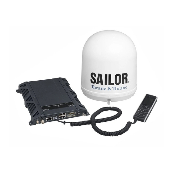
• Part numbers and options SAILOR 900 VSAT system The SAILOR 900 VSAT is a unique stabilized maritime VSAT antenna system operating in the Ku-band (10.7 to 14.5 GHz). It provides bi-directional IP data connections both on regional satellite beams and quasi-global Ku-band satellite networks. The system only requires a single 50 Ohm cable to provide the Above Deck Unit with both DC power, data and control information.
-
Page 26: Chapter 2 Introduction
SAILOR 900 VSAT system The following figures show the SAILOR 900 VSAT system with its two variants of ACUs. Above Deck Unit (ADU) Antenna Control Unit (ACU) Figure 2-1: Above Deck Unit and Antenna Control Unit (ACU) Above Deck Unit (ADU) Antenna Control Unit (ACU) (1 U 19”…
-
Page 27: Above Deck Unit (Adu)
2.1.1 Above Deck Unit (ADU) The SAILOR 900 VSAT Above Deck Unit is a 103 cm VSAT stabilised tracking antenna, consisting of a suspended antenna with a standard global RF configuration. The Above Deck Unit’s weight is around 135 kg. It is stabilized by heavy duty vibration dampers in 3-axis (plus skew) and can be used in environments with elevations of -25°…
-
Page 28: Figure 2-4: Above Deck Unit Modules 1/2
SAILOR 900 VSAT system Modules in the SAILOR 900 VSAT Above Deck Unit Figure 2-4: Above Deck Unit modules 1/2 1. GPS module. 2. VSAT Interface Module (VIM). 3. DC-Motor Driver Module for cross elevation (DDM). 4. Cross elevation motor and encoder.
-
Page 29: Chapter 2 Introduction
SAILOR 900 VSAT system 10. Block Up Converter (BUC). (behind cable screen, not visible on photo) 11. Low Noise Block downconverter (x2) (LNB). (not visible on photo) 12. Ortho Mode Transducer (OMT). (not visible on photo) 13. Inertial Sensor Module (ISM).
-
Page 30: Antenna Control Unit (Acu)
SAILOR 900 VSAT system SAILOR 900 VSAT Above Deck Unit interface All communication between the Above Deck Unit and the ACU passes through a single standard 50 Ohm cable (with N connector) through the rotary joint. No cable work is required inside the radome.
-
Page 31: Figure 2-6: Sailor 900 Vsat Acu, Connector Overview
The 19” rack version of the ACU has additionally a LAN connector at the front for accessing the service port from the ACU front panel. Service port Figure 2-7: SAILOR 900 VSAT ACU, 19” rack version 98-133400-B Chapter 2: Introduction…
-
Page 32: Figure 2-8: Antenna Control Unit For Bulkhead Installation
SAILOR 900 VSAT system Installation friendly The ACU comes in two models: Wall or desktop installation (bulkhead) or in a 19” rack version. Figure 2-8: Antenna Control Unit for bulkhead installation Figure 2-9: Antenna Control Unit for 19” rack installation Service friendly You can do remote diagnostics and service with the ACU.
-
Page 33: Vsat Modem Unit (Vmu)
ESUPPORT. 2.1.4 Satellite type approvals For a list of satellite type approvals see the SAILOR 900 VSAT data sheet at thrane.com. 2.1.5 Power supply To provide DC power to the SAILOR 900 VSAT you can use the TT-6080A Power Supply.
-
Page 34: Part Numbers And Options
Part numbers and options Part numbers and options 2.2.1 Applicable Thrane & Thrane model- and part numbers This Installation Manual is for the SAILOR 900 VSAT system and is applicable to the model- and part numbers below: T&T part number Model number Description…
-
Page 35: Chapter 3 Installation
• Installation of the VMU Unpacking 3.1.1 What’s in the box Unpack your SAILOR 900 VSAT ADU and check that the following items are present: • ADU with 4 lifting brackets (already mounted) • Package with bolts and washers ACU (bulkhead)
-
Page 36: Initial Inspection
Unpacking ACU (19” rack version) Unpack your SAILOR 900 VSAT ACU (19” rack version) and check that the following items are present: • 1 x Ethernet cable (2 m) • 1 x Ethernet cable (short) • Power connector • 2 x 75 Ohm coax cables F-F (1m), for Rx and Tx •…
-
Page 37: Site Preparation
For optimum system performance, some guidelines on where to install or mount the different components of the SAILOR 900 VSAT System must be followed. It is recommended to mount the ADU in a location with as much 360° free line of sight to the satellite as possible while making sure that the support structure fulfills the requirements for the mast foundation.
-
Page 38: Figure 3-1: Signal Degradation Because Of Obstructing Objects
Site preparation large objects that may block the signal. To avoid obstruction elevate the ADU by mounting it on a mast or on a mounting pedestal on a deck or deck house top. Look angle: — 25° to +125° Obstruction Figure 3-1: Signal degradation because of obstructing objects The ADU is stabilized in 3-axis (plus skew) and can be used in environments with elevations of -25°…
-
Page 39: Blocking Zones — Azimuth And Elevation
Elevation: — 25° to +30° Figure 3-3: Blocking zone with no-transmit zones, elevation angle (example) The blocking zones are set up in the SAILOR 900 VSAT built-in web interface. For further information see Setting up Blocking zones (RX and TX) on page 6-19.
-
Page 40: Safe Access To The Adu: Radiation Hazard
Safe access to the ADU: Radiation hazard The SAILOR 900 VSAT ADU radiates up to 49 dBW EIRP. This translates to a minimum safety distance of 30 m from the ADU while it is transmitting, based on a radiation level…
-
Page 41: Ship Motion And Offset From The Ship’s Motion Centre
Site preparation 3.2.5 Ship motion and offset from the ship’s motion centre Even though it is recommended to mount the ADU high, keep the distance between the ADU and the ship’s motion centre as short as possible. The higher up the ADU is mounted, the higher is the linear g force applied to the ADU.
-
Page 42: Adu Mast Design: Foundation And Height
Site preparation 3.2.6 ADU mast design: Foundation and height The ADU mast must be designed to carry the weight of the ADU unit, which is approximately 135 kg (+ the weight of the mast flange). The mast must also be able to withstand onboard vibrations and wind speeds up to 110 knots on the radome, even in icing conditions.
-
Page 43: Figure 3-8: Adu Mast Flange, Distance To The Welded Seam
Site preparation Allow sufficient space so the nut is free of the welded seam and there is room for tools . Clearance hole for M12 bolts Figure 3-8: mast flange, distance to the welded seam CAUTION! Avoid sharp edges where the flange is in direct contact with the radome.
-
Page 44: Figure 3-10: Free Mast Length And Bracing For A Tall Mast
Site preparation Mast length and diameter The placement of the ADU must ensure a rigid structural connection to the hull or structure of the ship. Parts of the ship with heavy resonant vibrations are not suitable places for the ADU. A small platform or short mast shall provide rigid support for the ADU fastening bolts and a rigid interface to the ship.
-
Page 45: Table 3-2: Mast Dimensions Without Braces
Site preparation SAILOR 900 VSAT ADU mast length The below tables show the minimum dimensions for a SAILOR 900 VSAT ADU mast with and without stays or wires. Note that the values are only guidelines — always consider the environment and characteristics of the ship before deciding on the mast dimensions.
-
Page 46: Table 3-4: Mast Dimensions With 2 Braces
Site preparation Max. free Outer Outer Wall Thickness mast Diameter Mast with 2 braces Diameter Thickness for brace length (steel), for brace (mm) (mm) (mm) (mm) Table 3-4: Mast dimensions with 2 braces 3-12 Chapter 3: Installation 98-133400-B…
-
Page 47: Interference
ADU performance. RF emission from radars might actually damage the ADU. The SAILOR 900 VSAT ADU itself may also interfere with other radio systems. Radar It is difficult to give exact guidelines for the minimum distance between a radar and the ADU because radar power, radiation pattern, frequency and pulse length/shape vary from radar to radar.
-
Page 48: Table 3-5: Minimum Radar Separation, X-Band
“d min.” is defined as the shortest distance between the radar antenna (in any position) and the surface of the SAILOR 900 VSAT ADU. X-band (~ 3 cm / 10 GHz) damage distance SAILOR 900 VSAT ADU Radar d min.
-
Page 49
Even at distances greater than “d min.” in the previous section the radar might still be able to degrade the performance of the SAILOR 900 VSAT system. The presence of one or more S or X-band radars within a radius up to 100 m may cause a minor degradation of the Ku-band connection. -
Page 50: Figure 3-12: Recommended Distance To Transmitters (M) For Frequencies Below 1000 Mhz
Site preparation Other transmitters See the following figure for minimum recommended distance to transmitters in the frequency range below 1000 MHz. Distance to transmitters (m) Figure 3-12: Recommended distance to transmitters (m) for frequencies below 1000 MHz 3-16 Chapter 3: Installation 98-133400-B…
-
Page 51: Other Precautions
Site preparation 3.2.8 Other precautions Condensation and water intrusion If possible, install the radome such that direct spray of seawater is avoided. In some weather condition there may occur condensation inside the radome. The drain tube is designed to lead any water away from inside the radome. Make sure the ADU’s drain tube is open and that there it free space between the drain tube and the mounting surface so water can escape and there is ventilation for the ADU.
-
Page 52: Installation Of The Adu
Installation of the ADU Installation of the ADU The ADU is shipped fully assembled. You have to install it on the mast and attach the ADU cable. WARNING! Use a strong webbed sling with a belt to lift the ADU without damaging the radome. Make sure that the sling can carry the ADU’s weight (135 kg, 288 lbs).
-
Page 53: Installing The Adu
Figure 3-15: Free space for access to the service hatch The ADU does not have to be aligned with the bow-to-stern line of the ship. When configuring the SAILOR 900 VSAT you make an azimuth calibration to obtain the correct azimuth of the ADU.
-
Page 54: Figure 3-16: Adu Installation, Webbed Sling Attached To The 4 Lifting Brackets
Installation of the ADU 4. Attach a webbed, four-part sling with a belt to all 4 lifting brackets. Figure 3-16: ADU installation, webbed sling attached to the 4 lifting brackets 5. Attach 2 tag lines of suitable length to 2 lifting brackets and man them. 6.
-
Page 55: Figure 3-18: Connecting The Adu Cable
Installation of the ADU 8. Put the coaxial ADU cable through the protection plate as shown in the following figure, and connect the N connector of the ADU cable to the ADU (see picture series below). Protection plate N connector Figure 3-18: Connecting the ADU cable Ensure that the connector assembly is properly protected against seawater and corrosion.
-
Page 56: Grounding The Adu
Installation of the ADU 3.3.2 Grounding the ADU The ADU must be grounded using the mounting bolts. If the ADU cannot or should not be electrically connected directly to the mounting surface, you can use a separate grounding cable to make the connection between the ADU and the common ground to which the ACU is also connected.
-
Page 57: Installation Of The Acu (Bulkhead)
3-24 and the appendix Grounding and RF protection on page D-1 for details about grounding. 3. Connect all cables. See Interfaces of the SAILOR 900 VSAT ACU on page 4-1 for a description of the ACU connectors. 4. Secure the cables using cable strips.
-
Page 58: Grounding The Acu (Bulkhead)
(minimum cross section: 4 mm Ground stud Figure 3-20: SAILOR 900 VSAT ACU, bulkhead version, ground stud 3.4.3 SAILOR 900 VSAT ACU (bulkhead) with cable support You can mount a Cable Relief for the ACU (bulkhead).
-
Page 59: Figure 3-21: Mounting The Cable Relief 1/2
Installation of the ACU (bulkhead) To mount the cable relief, do as follows: 1. Remove the two rubber washers from the bottom of the ACU at the connector panel end. The threaded bushings underneath the rubber washers are used for mounting the cable support.
-
Page 60: Installation Of The 19″ Rack Version Of The Acu
3-24 and the appendix Grounding and RF protection on page D-1 for details about grounding. 5. Connect all cables. See Interfaces of the SAILOR 900 VSAT ACU on page 4-1 for a description of the ACU connectors. 6. Secure the cables to the cable relief using cable strips.
-
Page 61: Grounding The 19″ Rack Version Of The Acu
Installation of the 19” rack version of the ACU Connectors of the 19” rack version of the ACU For a description of the connectors see Connectors of the ACU on page 3-23. The 19” rack version of the ACU has additionally a LAN connector at the front for accessing the service port from the ACU front panel.
-
Page 62: Installation Of The Vmu
Installation of the VMU Installation of the VMU For a list of supported VSAT modems see the SAILOR 900 VSAT data sheet. For the latest status of supported VMUs see http://extranet.thrane.com/ and click ESUPPORT. 3.6.1 General mounting considerations — VMU 1.
-
Page 63: Chapter 4 Interfaces
Chapter 4 Interfaces This chapter is organised in the following sections: • Interfaces of the SAILOR 900 VSAT ACU • Interfaces of the VMU Interfaces of the SAILOR 900 VSAT ACU 4.1.1 ACU bulkhead — LEDs, display and keypad Figure 4-1: ACU bulkhead, LEDs, display and keypad 4.1.2…
-
Page 64: Acu Bulkhead — Connector Panel — Overview
Interfaces of the SAILOR 900 VSAT ACU 4.1.3 ACU bulkhead — Connector panel — overview LAN 2 Rx Out Tx in RS-422 LAN 1 Modem Ctrl. Modem Ctrl. NMEA RS-232 LAN 3 LAN 4 Power On/Off Service port Figure 4-3: ACU bulkhead, connector panel overview 4.1.4…
-
Page 65: Dc Input Connector
Interfaces of the SAILOR 900 VSAT ACU 4.1.5 DC Input connector Provide DC power to the ACU, for example by using the TT-6080A Power Supply or 24 VDC from the vessel’s power supply. DC input: Female plug (Weidmuller, Part number 1930050000) for wires up to…
-
Page 66: Adu Connector
Interfaces of the SAILOR 900 VSAT ACU 4.1.6 ADU connector There is just one cable from the ACU to the ADU. This is used to power the ADU, supply 10 MHz clock, handle all communication between ACU and ADU, and deliver the VSAT Rx and Tx signals.
-
Page 67: Nmea 0183/2000 Connector
Interfaces of the SAILOR 900 VSAT ACU 4.1.8 NMEA 0183/2000 connector (Prepared for NMEA 2000) Connect the ship’s gyro to this connector. Wire Outline numbe Pin function color — — NET-H (NMEA White 2000) NET-L (NMEA 2000) Blue NET-S (NMEA 2000)
-
Page 68: And Rs-422 Connectors
Interfaces of the SAILOR 900 VSAT ACU • Propagation delay: 5 nanoseconds per meter, maximum • 15 Twists (minimum) per meter 4.1.9 RS-232 and RS-422 connectors These connectors are used to access and configure the connected VSAT modem and for ACU control.
-
Page 69: Lan1, Lan2, Lan3 And Lan4 Connectors
Interfaces of the SAILOR 900 VSAT ACU Outline Pin function number Ground Line A RXD (+) Line B TXD (-) Ground Ground — Line A RXD (-) Line B TXD (+) — Table 4-6: RS-422 connector, male, outline and pin assignment 4.1.10…
-
Page 70: Table 4-7: Ethernet Connector, Outline And Pin Assignment
Interfaces of the SAILOR 900 VSAT ACU Outline numbe Pin function Wire color white/orange orange white/green Not connected blue Not connected white/blue green Not connected white/brown Not connected brown Table 4-7: Ethernet connector, outline and pin assignment Cable type: CAT5, shielded.
-
Page 71: Interfaces Of The Vmu
Interfaces of the VMU Interfaces of the VMU For interfaces of the VMU and how to connect a VMU correctly to the ACU see the following sections and the user documentation of the VMU. 4.2.1 Connecting an iNFINITI® 5000 Series Satellite Router Connect the VSAT modem to the ACU as shown in the figure below: Antenna Antenna…
-
Page 72: Connecting An Evolution® X5 Satellite Router
Interfaces of the VMU 4.2.2 Connecting an Evolution® X5 Satellite Router Connect the VSAT modem to the ACU as shown in the figure below: Antenna Antenna Rx Out RS-232 LAN 1 Tx In Rx In Console Tx Out Evolution X5 Satellite Router Figure 4-8: Connecting an Evolution X5 Satellite Router Cable 3 is only used when using OpenAMIP protocol.
-
Page 73: Connecting A Comtech 570 L Or 625 Satellite Modem
Interfaces of the VMU 4.2.3 Connecting a Comtech 570 L or 625 Satellite Modem Connect the VSAT modem to the ACU as shown in the figure below: Antenna Antenna Rx Out RS-232 Tx In Alarms Remote control 950-1950 MHz 950-1950 MHz Comtech 570 L-Band Satellite Modem Figure 4-9: Connecting a Comtech 570 L or 625 Satellite Modem Cable…
-
Page 74
Interfaces of the VMU 4-12 Chapter 4: Interfaces 98-133400-B… -
Page 75: Chapter 5 Connecting Power
Chapter 5 Connecting power This chapter is organised in the following sections: • Power source • Power cable selection • Connecting power • Power up Power source There are different options for the power supply: • The 24 VDC ship supply provides power for the ACU. •…
-
Page 76: Power Cable Selection
Power cable selection Power cable selection 5.2.1 Source impedance The maximum length of the power cable depends on the type of cable used and the source impedance of the DC power installation in the ship. The maximum allowed source impedance depends on the usage of the power range of the terminal DC input (Start up voltage: 22 VDC guaranteed, operating range: 20 —…
-
Page 77: Power Cable Recommendations
Power cable selection Figure 5-1: Measuring the ship source impedance 5.2.3 Power cable recommendations Overview The ACU is delivered with a power connector (PCB plug-in connector, female plug, Weidmuller, Part number 1930050000), which accepts wires up to AWG10/6 mm • When installing the power cable, install positive and negative supply wires closely together side by side to keep cable inductance low.
-
Page 78: Connecting Power
Connecting power The length is multiplied by 0.5 above because there are two conductors in the cable. If the TT-6080A Power Supply is used, use R = 0 mOhm. source Examples for using the TT-6080A Power Supply: AWG11 =0.5 x (60 mOhm-0)/4.8 mOhm/m = 6.2 m AWG10 =0.5 x (60 mOhm-0)/3.8 mOhm/m = 7.9 m Connecting power…
-
Page 79: Power Up
• ADU POST • READY This may take some time (up to a couple of minutes). Now the SAILOR 900 VSAT is ready to be calibrated (for first time power up) or receive data from the VSAT modem (when in normal operation). The ACU display shows the following message:…
-
Page 80
Power up Initialisation in daily use Once the system is configured and a satellite profile is active, the startup sequence is as follows: • ACU POST • ADU Initializing • ADU SW upload (If the software versions in the ADU and ACU are not the same, a software update is done during startup.) •… -
Page 81: Chapter 6 Configuration
Introduction to the built-in web interface 6.1.1 Overview Use the built-in web interface of the SAILOR 900 VSAT ACU to make a full configuration of the SAILOR 900 VSAT with the correct VMU, the satellite positions you intend to use and other parameters.
-
Page 82: Connecting To The Web Interface
To connect to the web interface of the ACU do as follows: 1. Power up the SAILOR 900 VSAT system, i.e. switch on the ACU. Wait until the LEDs on the front plate of the ACU show that the system is ready to be configured.
-
Page 83: Calibration Of The Sailor 900 Vsat
Calibration of the SAILOR 900 VSAT 5. The web interface opens directly with the DASHBOARD page. Figure 6-3: SAILOR 900 VSAT Dashboard For a detailed introduction to the web interface see Overview and navigation on page 6-8. Calibration of the SAILOR 900 VSAT You must align the ADU with the vessel’s gyro compass.
-
Page 84: Setting Up A Service Profile For Calibration
Calibration of the SAILOR 900 VSAT 6.2.1 Setting up a service profile for calibration To set up a service profile for calibration, do as follows: 1. Add a VSAT modem profile for calibration. This is not a physical modem, but a ‘virtual’…
-
Page 85: Figure 6-5: Service Profile, Add Satellite Information
Calibration of the SAILOR 900 VSAT 5. Select Satellite profiles > New entry. Enter the name of the satellite profile for calibration (a name of your own choice) and select the VSAT modem Service (created in step 3.), click Apply.
-
Page 86: Calibration Of Azimuth And Cable
Calibration of the SAILOR 900 VSAT 6.2.2 Calibration of azimuth and cable First you must set up a service profile, see 6.2.1. Note The ship must not move during the calibration procedure. The satellite must be visible from the location of the installation.
-
Page 87
The screen is not automatically updated when new data are available from the SAILOR 900 VSAT. You may click the button Refresh in the web interface to update the screen. 4. Click Start in the section Azimuth calibration and wait 5 minutes for the calibration to finish. -
Page 88: Configuration With The Web Interface
Configuration with the web interface Configuration with the web interface 6.3.1 Overview and navigation Topics in the web interface Use the site map to get an overview over the existing menus, submenus and topics. You can click on each menu in the site map to go directly to the page or display the respective submenu.
-
Page 89: Figure 6-8: Sections Of The Web Interface
Configuration with the web interface Navigation The web interface consists of the following sections: Figure 6-8: Sections of the web interface 1. The navigation pane holds the main menu. Clicking an item in the menu opens a submenu in the navigation pane or a new page in the contents section. 2.
-
Page 90: Table 6-2: Web Interface: Icons
Configuration with the web interface Icons in the icon bar The following icons may appear in the icon bar in the web interface: Icon Explanation An event is active. Click the icon to see a list of active events. For explanations of the event messages, see Event messages —…
-
Page 91
Configuration with the web interface To disable the use of a Proxy server completely, do as follows: Note The following description is for Microsoft Internet Explorer. If you are using a different browser, the procedure may be different. 1. In Microsoft Internet Explorer, select Tools > Internet Options > Connections > LAN Settings. -
Page 92: Using The Dashboard
Configuration with the web interface 6.3.2 Using the Dashboard The Dashboard is the first screen that is displayed when the user or administrator enters the IP address of the web interface of the ACU. The Dashboard is used for set up and selection of satellite and modem profiles, control and inspection of ongoing communication and for viewing properties and status of the ACU and ADU.
-
Page 93: Table 6-3: Web Interface, Sailor 900 Vsat Parameters On Dashboard
Auto-selected by VSAT modem TX RF frequency Auto-selected by VSAT modem BUC Lo frequency 12.8 GHz (system parameter) Tracking RF Enter in satellite profile. frequency Table 6-3: Web interface, SAILOR 900 VSAT parameters on DASHBOARD 98-133400-B Chapter 6: Configuration 6-13…
-
Page 94: Table 6-4: Web Interface, Vsat Modem Parameters On Dashboard
SAILOR 900 VSAT Description parameter ACU part name, Part names, serial numbers for ACU and ADU, software ADU part name, version of the SAILOR 900 VSAT, read out from the units ACU serial number, connected. ADU serial number, Software version Management IP…
-
Page 95: Satellite Profiles And Vsat Modem Profiles
Configuration with the web interface 6.3.3 Satellite profiles and VSAT modem profiles Satellite profiles On the page Satellite profiles you add, edit and delete satellite profiles. A satellite profile contains all settings that are necessary for a successful connection to the satellite, including a VSAT modem profile.
-
Page 96: Figure 6-11: Web Interface: Settings, Satellite Profiles — New Entry (Example)
Configuration with the web interface Satellite profiles — New entry and Edit Each satellite profile has one assigned VSAT modem profile. Figure 6-11: Web interface: SETTINGS, Satellite profiles — new entry (example) To add or edit a satellite profile, do as follows: 1.
-
Page 97: Figure 6-12: Web Interface: Settings, Vsat Modem Profiles — List (Example)
Configuration with the web interface VSAT modem profiles A VSAT modem profile contains all VSAT modem settings that are necessary for a successful connection to the satellite. The data you have to fill in are provided by your VSAT service and modem provider. You must add at least one VSAT modem profile. Figure 6-12: Web interface: SETTINGS, VSAT modem profiles —…
-
Page 98: Figure 6-13: Web Interface: Settings, Vsat Modem Profiles — New Entry (Example)
Configuration with the web interface To add or edit a VSAT modem profile, do as follows: 1. Go to SETTINGS > VSAT modem profiles and click New entry or Edit. Figure 6-13: Web interface: SETTINGS, VSAT modem profiles — new entry (example) 2.
-
Page 99: Setting Up Blocking Zones (Rx And Tx)
Configuration with the web interface 6.3.4 Setting up Blocking zones (RX and TX) On this page you define blocking zones, i.e. NO TX and RX zones, enter azimuth values and elevation angles for each blocking zone. You must select Active to enable a blocking zone.
-
Page 100: Figure 6-15: Blocking Zone, Example: 315 — 45 Degrees
Configuration with the web interface 3. Azimuth: Enter start and stop azimuth value in degrees for the blocking zone. Values allowed: 0 to 360 degrees. Enter clockwise. 360° 000° 315° 45° 270° 90° Antenna Blocking zone: 315° — 45° 225° 135°…
-
Page 101: Configuring The Lan Network
Configuration with the web interface 6.3.5 Configuring the LAN network The ACU has four 10/100 Mbit Ethernet ports labelled LAN port 1, 2, 3 and 4. The ports are divided in three groups, each operating in its own network. To configure the LAN network go to SETTINGS > Network. Figure 6-17: Web interface: SETTINGS, Network (LAN connectors) Make sure that the 3 networks do not use IP address Important…
-
Page 102
Configuration with the web interface Preferred use LAN port 3 is dedicated as the service port. By default this port has the IP address 192.168.0.1; the current value can be displayed in the ACU display and on the DASHBOARD, Management IP address. In a 19” rack mount it is recommended to connect LAN port 3 to the front port (via rear connector, see the figure ACU rack version, connector panel overview on page 4-2), for… -
Page 103: E-Mail Setup
Configuration with the web interface 6.3.6 E-mail setup To be able to send diagnostics and statistics reports using e-mail you must set up the parameters shown on the screen below. Contact your IT department for the specific data To configure the e-mail setup, do the following: 1.
-
Page 104: Sending Statistics Reports
SAILOR 900 VSAT can send a statistics report at fixed intervals. This report contains historical information from the SAILOR 900 VSAT of up to 1 month. It is sent as a zipped attachment to an e-mail. The file format is a comma separated text file. The report can then be processed in spreadsheet applications, e.g.
-
Page 105: Table 6-6: Parameters Recorded In A Statistics Report
Configuration with the web interface Parameter recorded Description UTC. (s) UTC in seconds and date format for the data UTC (YYYY-MM-DD hh:mm) set. RSSI.Av Received signal strength (average, RSSI.Max maximum and minimum value) for the RSSI.Min sampling interval POS.Lat (degree) Latitude value of position POS.Long (degree) Longitude value of position…
-
Page 106: Figure 6-20: Statistics — How To Read Data For A Range
Configuration with the web interface Parameter recorded Description Pos Ok (%) Valid position, in percent of the 2 minute interval VMU Connection (%) No link with VSAT modem, in percent of the 2 minute interval Blocking (%) Ship in blocking zone, in percent of the 2 minute interval Table 6-6: Parameters recorded in a statistics report (Continued) 360°…
-
Page 107: Sending A Diagnostic Report
Configuration with the web interface The following figure shows an example of a statistics report in MS Excel 2007. Figure 6-21: Statistics report (example) 6.3.8 Sending a diagnostic report You can send automatically generated diagnostic reports at fixed intervals. The diagnostic report contains information relevant for the service personnel during troubleshooting.
-
Page 108: Upload
For further details see Generating a diagnostic report on page 9-2. 6.3.9 Upload For uploading new software to the SAILOR 900 VSAT see Software update on page 9-4. 6.3.10 Administration In this section of the web interface you can configure the following administrative settings: •…
-
Page 109: Figure 6-23: Web Interface: Administration, Change Administrator Logon
Configuration with the web interface Changing the administrator password 1. After entering the administrator user name and password in the ADMINISTRATION page, locate the section Change administrator logon. Figure 6-23: Web interface: Administration, change administrator logon 2. Type in the existing user name. 3.
-
Page 110
Configuration with the web interface 3. Type in the reset code obtained from your service partner and click Reset. 4. Type in the user name Admin and the default password 1234. 5. Click Logon. For information on how to change the password, see the section Changing the administrator password on page 6-29. -
Page 111: Figure 6-25: Web Interface: Administration, User Permissions
Configuration with the web interface Setting up user permissions You can manage user access to certain functions of the SAILOR 900 VSAT system. You can allow or deny users that are not administrators access to certain functions and make these pages read-only. This is useful if you want to protect the system against unintended changes or tampering of the system.
-
Page 112: Figure 6-26: Web Interface: Administration, Factory Default
Configuration with the web interface Resetting to factory default When resetting SAILOR 900 VSAT to factory default, the following settings are deleted: • All satellite profiles • All VSAT modem profiles • Blocking zones • Network setup • User permissions •…
-
Page 113: Keypad Of The Sailor 900 Vsat Acu
Keypad of the SAILOR 900 VSAT ACU Keypad of the SAILOR 900 VSAT ACU 6.4.1 ACU display and keypad In the ACU display you can see the current state of the system. You can also see events (warnings, errors and information) and how the system has been configured. Use the keypad to navigate through the menu tree.
-
Page 114: Navigating The Menus
Keypad of the SAILOR 900 VSAT ACU Display text Explanation SAT:151.2 W Satellite position of currently active satellite profile. Example: 151.2° West. RX:H RX polarisation of currently active satellite profile. Example: Horizontal. 11.362/10.75 Rx RF frequency and LNB LO Frequency TX:X TX polarisation of currently active satellite profile.
-
Page 115: The Menu Tree
Keypad of the SAILOR 900 VSAT ACU 6.4.3 The menu tree In the menu tree you can see how the system has been configured. You can also enter satellite information directly, if it is necessary to change the satellite information and you cannot use a connected PC and the web interface.
-
Page 116: Table 6-8: Top-Level Menus Of The Acu
Description menu MAIN View with current status of the SAILOR 900 VSAT. Example when logged on to the satellite: This view is displayed after a time out of 10 minutes. Press any key (except left arrow) to enter the menu at MAIN.
-
Page 117: Table 6-9: Antenna Menu Of The Acu
Keypad of the SAILOR 900 VSAT ACU Menu descriptions ANTENNA Description menu POINTING ANTENNA: READY (no satellite profile selected), ACQUISIITON (in the process of logging on), TRACKING (tracks the current satellite, operational) ELEVATION: Current elevation angle of the antenna AZIMUTH: Current azimuth of the antenna, with reference…
-
Page 118: Table 6-11: Network Menu Of The Acu
Other modem: Signal level in dB. Table 6-10: MODEM menu of the ACU (Continued) NETWORK Description menu MANAGEMENT Current IP address of the SAILOR 900 VSAT web interface (default: 192.168.0.1). MANAGEMENT Current netmask of the SAILOR 900 VSAT web interface MASK (default: 255.255.255.0).
-
Page 119: Adjusting Brightness Of The Display
Keypad of the SAILOR 900 VSAT ACU EVENT menu Description <EVENT> In this menu all active events are listed. Use to go through the active events. Events can be of the type WARNING or ERROR. For a list of events see Event messages — overview on page E-1.
-
Page 120
Keypad of the SAILOR 900 VSAT ACU 6-40 Chapter 6: Configuration 98-133400-B… -
Page 121: Chapter 7 Installation Check
Chapter 7 Installation check Now that you have installed the system, you can test the system to verify it is ready for customer delivery. Follow the check lists below to test the system for proper operation. • Installation check list: Antenna •…
-
Page 122: Chapter 7 Installation Check
Installation check list: Antenna Step Task Further information Done Check that the mounting height See Ship motion and offset of the antenna is in accordance from the ship’s motion centre with the ship’s min. roll period. on page 3-7 Make sure that the requirements See ADU mast design: for mast foundation and height, Foundation and height on…
-
Page 123: Installation Check List: Acu, Connectors And Wiring
Installation check list: ACU, connectors and wiring Installation check list: ACU, connectors and wiring Step Task Further information Done Check that the ACU is grounded See Grounding the ACU correctly, using the mounting (bulkhead) on page 3-24 or bolts and washers. Grounding the 19”…
-
Page 124: Table 7-2: Installation Check List: Acu, Connectors And Wiring
Installation check list: ACU, connectors and wiring Step Task Further information Done Check connection of the VSAT Visual inspection of the modem: connector panel of the ACU and the VSAT modem. COMTECH only!: Check that the ACU RS-232 port is connected to the Remote Control port of the VMU using the included serial cable.
-
Page 125: Installation Check List: Functional Test In Harbor
Installation check list: Functional test in harbor Installation check list: Functional test in harbor Step Task Further information Done Check that the antenna is The logon LED in the ACU display locked to the satellite must be steady green and the display shows: TRACKING.
-
Page 126
Installation check list: Functional test in harbor Chapter 7: Installation check 98-133400-B… -
Page 127: Figure 8-1: Sailor 900 Vsat Quick Guide — Web Interface And Satellite Profiles
For detailed information about the SAILOR 900 browser. The built-in web interface opens VSAT system see the SAILOR 900 VSAT Installa- directly with the DASHBOARD. tion & user manual. Figure 8-1: SAILOR 900 VSAT Quick Guide — web interface and satellite profiles 98-133400-B…
-
Page 128: Figure 8-2: Sailor 900 Vsat Quick Guide — Viewing System Parameters
The last active satellite SAILOR 900 VSAT system see the SAILOR profile will be selected. 900 VSAT Installation & user manual. thrane.com Figure 8-2: SAILOR 900 VSAT Quick Guide — Viewing system parameters Chapter 8: Daily use — Quick guide 98-133400-B…
-
Page 129: Chapter 9 Service
Chapter 9 Service In this chapter you find the following sections: • Getting support: Helpdesk • Software update • Status signalling with LEDs and status messages • Removal and replacement of the ACU • Removal and replacement of ADU modules •…
-
Page 130: Getting Support: Helpdesk
Clicking the link Legal notice provides licence text for the source code of the parts of SAILOR 900 VSAT software that falls under free and open source software. If you need help with ACU or ADU related issues call your service provider.
-
Page 131
Once an event is cleared, it is not displayed any longer. Self test You can start a self test of the SAILOR 900 VSAT ADU and ACU. 1. Click Self test in the HELP DESK page. -
Page 132: Software Update
Software update should only be done by qualified service Note personnel. 1. Power up the SAILOR 900 VSAT system, i.e. switch on the ACU. Wait until the LEDs on the front plate of the ACU show that the system is ready to be configured. • Power LED: Green •…
-
Page 133: Verifying The Software Update
Software update 5. The web interface opens directly with the DASHBOARD page. 6. Click SERVICE from the left navigation pane. The Upload page is displayed. Figure 9-4: Web interface: SERVICE, Upload 7. The Current software version field shows the current software version. 8.
-
Page 134: Figure 9-5: Verifying Software Update
Software update 3. When the POST has finished, the green Pass/Fail LED on the front of the ACU must become steadily green. Verify that the Pass/Fail LED is not red nor flashing orange once every 2 seconds. Wait until the Pass/Fail LED is green. 4.
-
Page 135: Status Signalling With Leds And Status Messages
ACU, see Viewing the Event list on page 9-15. Means of signalling The SAILOR 900 VSAT system provides various methods for signalling the status of the system. • LEDs on the front panel of the ACU are used to signal: •…
-
Page 136: Leds Of The Adu Modules
Status signalling with LEDs and status messages 9.3.1 LEDs of the ADU modules Each ADU module has a Power and a Service LED. Behavior Description Power Steady green Power supply OK No power Service Steady green Module ok, application running. Flashing green Waiting for upload Flashing red/green…
-
Page 137: Leds In The Acu
Status signalling with LEDs and status messages 9.3.2 LEDs in the ACU The ACU has 3 LEDs: Power, Logon and Fail/Pass LED. LEDs Figure 9-6: LEDs on the ACU LEDs Figure 9-7: LEDs on the ACU, 19” rack version Behavior Description Power Steady green…
-
Page 138
Status signalling with LEDs and status messages Behavior Description Fail/Pass Steady red A fault which prevents operation is present in the system (ACU, ADU, MODEM). Flashing green A Power On Self Test (POST) or Person Activated Test (PAST) in progress. The current status is displayed. -
Page 139: Removal And Replacement Of The Acu
Removal and replacement of the ACU Removal and replacement of the ACU There are no parts in the ACU that you can remove or replace. If the ACU malfunctions, remove it from the wall, desk or rack and contact your Thrane & Thrane service partner for further repair or replacement.
-
Page 140: Removal And Replacement Of Adu Modules
Removal and replacement of ADU modules Removal and replacement of ADU modules For replacement of a module contact your Thrane & Thrane service partner. The figure below shows the modules and their position. Some modules are equipped with LEDs for status information and troubleshooting. Figure 9-10: ADU modules and motor stop switch 1.
-
Page 141: Figure 9-11: Above Deck Unit Modules (Continued)
Removal and replacement of ADU modules 6. DC-Motor Driver Module for elevation (on the side). 7. Elevation motor and encoder. (not visible on photo) 8. Polarisation Motor Module (PMM). (not visible on photo) 9. Polarisation motor and encoder. (not visible on photo) 10.
-
Page 142
Removal and replacement of ADU modules 17. Azimuth motor and encoder. (not visible on photo) 18. Rotary joint. (not visible on photo) 19. Feed horn. Before contacting your service partner check the LEDs on each module. See LEDs of the ADU modules on page 9-8 and LEDs in the ACU on page 9-9. -
Page 143: Initial Troubleshooting
Initial troubleshooting Initial troubleshooting Overview This section describes an initial check of the primary functions of the SAILOR 900 VSAT system, and provides some guidelines for troubleshooting, if one of the checks should fail. Generally, if a fault occurs without any obvious reason, it is always recommended to observe the LEDs and the ACU display showing the active events.
-
Page 144
Initial troubleshooting 9-16 Chapter 9: Service 98-133400-B… -
Page 145
Appendices… -
Page 147: Appendix A Technical Specifications
Appendix A Technical specifications SAILOR 900 VSAT system components A.1.1 General specifications Item Specification Frequency band Ku-band (VSAT) 10.70 to 12.75 GHz 13.75 to 14.50 GHz (extended) Reflector size 103 cm (40 inch) Certification (approval) Compliant with CE (Maritime), ETSI EN 302 340,…
-
Page 148: Adu
SAILOR 900 VSAT system components A.1.2 Item Specification Dimensions (overall) Diameter x Height: Ø 130 cm (51.3 inch) x H 150 cm (58.9 inch) Weight 135 kg (288 lbs) Antenna type, pedestal 3-axis (plus skew) stabilised tracking with integrated Antenna…
-
Page 149
SAILOR 900 VSAT system components Item Specification Satellite acquisition Automatic — w. Gyro/GPS compass input Vibration, operational Sine: IEC 945 (8.7.2), DNV A, MIL-STD-167-1 (5.1.3.3.5). Random: Maritime Vibration, survival Sine: IEC 945 (8.7.2) dwell, MIL-STD-167-1 (5.1.3.3.5) dwell. Random: Maritime survival Shock MIL-STD-810F 516.5 (Proc. -
Page 150: Acu
SAILOR 900 VSAT system components A.1.3 Item Specification Dimensions, rack mount 1 U, 19 inch H x W x D 4.4 x 48 x 33 cm (1.75 x 19 x 13 inch) Dimensions, bulkhead mount stand-alone unit H x W x D 4.3 x 25.5 x 27.8 cm (1.67 x 10.0 x 10.9 inch)
-
Page 151: Supported Vsat Modems
SAILOR 900 VSAT system components Item Specification Modem interface (control) iDirect openAMIP protocol & custom protocol Man Machine Interface (MMI) OLED (red) display, 5 push buttons, 3 discrete indicator LEDs and ON/OFF switch No transmit zones Programmable Table A-3: Technical specifications for the ACU (Continued) A.1.4…
-
Page 152: Outline Drawings
Outline drawings Outline drawings A.2.1 Figure A-1: Outline drawing: ADU Appendix A: Technical specifications 98-133400-B…
-
Page 153: Acu, Bulkhead
Outline drawings A.2.2 ACU, bulkhead Figure A-2: Outline drawing: ACU, bulkhead 98-133400-B Appendix A: Technical specifications…
-
Page 154: Acu, 19 Inch Rack
Outline drawings A.2.3 ACU, 19 inch rack Figure A-3: Outline drawing: ACU, 19 inch rack Appendix A: Technical specifications 98-133400-B…
-
Page 155
Appendix B VMU cable specifications This appendix contains cable specifications for cables between the ACU and a VSAT modem. • Modem Cable Comtech Serial & RSSI TT7016A • Modem Cable iNIFINITI iDirect VSAT modem 98-133400-B… -
Page 156: Appendix Bvmu Cable Specifications
Modem Cable Comtech Serial & RSSI TT7016A Modem Cable Comtech Serial & RSSI TT7016A Figure B-1: Modem Cable Comtech Serial & RSSI TT7016A Appendix B: VMU cable specifications 98-133400-B…
-
Page 157: Modem Cable Inifiniti Idirect Vsat Modem
Modem Cable iNIFINITI iDirect VSAT modem Modem Cable iNIFINITI iDirect VSAT modem Figure B-2: Modem Cable iNIFINITI iDirect VSAT modem 98-133400-B Appendix B: VMU cable specifications…
-
Page 158
Modem Cable iNIFINITI iDirect VSAT modem Appendix B: VMU cable specifications 98-133400-B… -
Page 159
Appendix C VMU settings requirements In this appendix you find detailed information how to set up supported VSAT modems. The following VSAT modems are described: • Open AMIP setup for iDirect INFINITI 5000 & Evolution X5 • Non-Open-AMIP setup for iDirect iNFINITI 5000 & Evolution X5 •… -
Page 160: Appendix Cvmu Settings Requirements
In general, OpenAMIP is not intended for any purpose except to permit a modem and the ACU to perform synchronized automatic beam switching. Thrane & Thrane A/S received OpenAMIP certification for SAILOR 900 VSAT from VT iDirect Inc on 22 September 2011.
-
Page 161: Figure C-1: Connecting Idirect Infiniti 5000 Series To The Acu (Openamip
Open AMIP setup for iDirect INFINITI 5000 & Evolution X5 See Connecting an iNFINITI® 5000 Series Satellite Router on page 4-9 and Connecting an Evolution® X5 Satellite Router on page 4-10 for details on cable connections and pin allocation for the RS-232 Console cable. Figure C-1: Connecting iDirect iNFINITI 5000 series to the ACU (OpenAMIP) Figure C-2: Connecting iDirect Evolution X5 to the ACU (OpenAMIP) 98-133400-B…
-
Page 162: Figure C-3: Supported Openamip Commands
Open AMIP setup for iDirect INFINITI 5000 & Evolution X5 Protocol The SAILOR 900 VSAT ACU supports all OpenAMIP commands except the X command which is optional. All the supported OpenAMIP commands are shown in the following figure. Figure C-3: Supported OpenAMIP commands…
-
Page 163: Sample Options File
Open AMIP setup for iDirect INFINITI 5000 & Evolution X5 Messages sent from the ACU to the Explanation VSAT modem s 1 1 Functional, Tx OK w 1 55.794010 12.52272 985523005 GPS valid, Latitude, Longitude, Time Table C-2: Messages sent from the ACU to the VSAT modem (examples) The iDirect modems only sends the satellite information once when booting.
-
Page 164
Open AMIP setup for iDirect INFINITI 5000 & Evolution X5 is_mesh = 0 disable_options_flash_command = 0 carrier_type = 0 [MOBILE] is_mobile = 1 tx_handshake_enabled = 0 gps_input = 2 latlong_interval = 300 latlong_fail_interval = 10 init_tx_power_offset = 0.000000 [MAPSERVER_0] hostname = 172.20.130.3 port = 5003 [BEAMS] beam_21 = PPS_Perf_Eval… -
Page 165: Table C-4: Information In The Vsat Modem Option File
Requirements option file [SATELLITE] The modem must use the following up and down conversion frequencies for rx and tx! SAILOR 900 VSAT has O-Type LNBs (Co-Pol & X-Pol) with following Local Oscillator (LO) down conversion frequencies: — 9.75 GHz — 10.25 GHz —…
-
Page 166: Configuration Examples (Openamip
Tx handshake must not be enabled in the iDirect modem. Example: “tx_handshake_enabled = 0” The SAILOR 900 VSAT can work either using the Rx 10 MHz [ODU] reference signal provided by the modem or using its own built- in 10 MHz reference signal. It is recommended to use the 10 MHz reference signal from the modem.
-
Page 167: Figure C-5: Satellite Profile, Openamip (Example
Open AMIP setup for iDirect INFINITI 5000 & Evolution X5 Figure C-5: Satellite profile, OpenAMIP (example) 98-133400-B Appendix C: VMU settings requirements…
-
Page 168: Non-Open-Amip Setup For Idirect Infiniti 5000 & Evolution X5
Non-Open-AMIP setup for iDirect iNFINITI 5000 & Evolution X5 Non-Open-AMIP setup for iDirect iNFINITI 5000 & Evolution X5 C.2.1 Protocol and interfaces Introduction The following sections describe the protocol and interface between the ACU and an iDirect Non-OpenAMIP modem. Non-OpenAMIP operation is normally used by service providers offering regional VSAT service.
-
Page 169: Console Port Settings
• Data bits: 8 • Parity: None • Stop bit: 1 Passwords The SAILOR 900 VSAT ACU will log in to the modem using root and user passwords. The default passwords are: • Root: P@55w0rd! • User: iDirect Supported commands After login to the modem the ACU will issue commands to the modem every second.
-
Page 170: Figure C-9: Requirements For Vsat Modem Option File, Non-Openamip
— 10.25 GHz — 10.75 GHz — 11.25 GHz The SAILOR 900 VSAT has an extended 8 Watt BUC with LO up conversion frequency of 12.8 GHz. The iDirect modem must be set to mobile unit and receive the GPS information from the ACU with the command “latlong <lat>…
-
Page 171: Configuration Examples (Non-Openamip
Non-Open-AMIP setup for iDirect iNFINITI 5000 & Evolution X5 C.2.3 Configuration examples (Non-OpenAMIP) Examples of modem profile and satellite configuration from the ACU web MMI are shown in the figures below. Figure C-10: VSAT modem profile, Non-OpenAMIP (example) Figure C-11: Satellite profile, Non-OpenAMIP (example) 98-133400-B Appendix C: VMU settings requirements C-13…
-
Page 172: Setup Of Comtech 570L, Ross Box & Acu
Setup of Comtech 570L, ROSS box & ACU Setup of Comtech 570L, ROSS box & ACU C.3.1 Protocols and interfaces The following sections describe how to connect an ACU, a Comtech570L VSAT modem, a ROSS box and an Ethernet switch. Connections Connect the ACU and Comtech 570L, ROSS box and Ethernet switch with the following cables:…
-
Page 173: Appendix D Grounding And Rf Protection
Grounding and RF protection Why is grounding required? D.1.1 Reasons for grounding Grounding the SAILOR 900 VSAT system is required for at least two reasons: • Safety: Lightning protection of persons and equipment. • Protection: ESD (ElectroStatic Discharge) protection of equipment. D.1.2 Safety First of all grounding of the system is required for safety reasons.
-
Page 174: Grounding Recommendations
Grounding Recommendations Grounding Recommendations D.2.1 Grounding the ACU The ACU should be grounded to the ship/hull. For this purpose you may use a short ADU cable and a grounding kit. Further, the ACU must be grounded at its grounding stud in order to ensure proper grounding if the short ADU cable is disconnected. For further information, see Grounding the terminal on page 2-33.
-
Page 175: Grounding The Adu
Grounding Recommendations D.2.2 Grounding the ADU You can ground the ADU to the ship/hull via one or more of its mounting bolts. Make sure to remove painting, dirt, grease etc. at the mounting holes in order to make good electrical contact to the hull. Use serrated washers when securing the mounting bolts and seal the joint with protective coating to avoid corrosion.
-
Page 176: Alternative Grounding For Steel Hulls
Alternative grounding for steel hulls Alternative grounding for steel hulls The following guidelines assume a two-wire, isolated grounding arrangement; that is no part of the circuit, in particular the battery negative, is connected to any ground potential or equipment. D.3.1 Grounding the ACU The ACU must be grounded to the ship with the short cable.
-
Page 177: Figure D-3: Grounding At A Dedicated Rf Ground (Alternative
Alternative grounding for steel hulls Recommended Alternative Antenna Antenna Base Plate Base Plate (Antenna isolated (electrically bonded to from the the hull ) the hull though the mast) Antenna grounded Antenna grounded with mounting bolts with separate cable Mast Mast (electrically bonded (electrically bonded to the steel hull)
-
Page 178: Alternative Grounding For Aluminum Hulls
Alternative grounding for aluminum hulls Alternative grounding for aluminum hulls The following guidelines assume a two-wire, isolated grounding arrangement; that is no part of the circuit, in particular the battery negative, is connected to any ground potential or equipment. D.4.1 Grounding the ACU The ACU must be grounded with the short cable.
-
Page 179: Alternative Grounding For Fiberglass Hulls
Alternative grounding for fiberglass hulls proximity to the shielded coax cable hence connecting the ADU to the ACU Grounding kit. A tinned heavy gauge wire (min. 6 mm ) can be used for this purpose. Antenna Heavy Gauge Wire Terminal Grounding Kit RF Ground (Capacitive OR Terminal…
-
Page 180: Figure D-5: Alternative Grounding For Fiberglass Hulls
Alternative grounding for fiberglass hulls proximity to the shielded coax cable hence connecting the ADU to the ACU Grounding kit. A tinned heavy gauge wire (min. 6 mm2) can be used for this purpose. Antenna Heavy Gauge Wire Terminal Grounding Kit Terminal RF Ground Plate Figure D-5: Alternative grounding for fiberglass hulls…
-
Page 181: Separate Ground Cable
Separate ground cable Separate ground cable D.6.1 Ground cable — construction When dealing with electrical installations in a marine environment, all wiring must be done with double insulated, tinned, high quality and if exposed also UV resistant cables. This shall also apply to the separate ground cable mentioned in the previous paragraphs.
-
Page 182: Isolation Of The Adu From The Mounting Base
Separate ground cable The ground cable must be connected at one of the mounting/grounding bolts on the ADU. Use bolts and washers of stainless steel and seal the joint with protective coating to avoid corrosion. If the ADU is to be isolated from the mounting base, shoulder bushings and washers must be used —…
-
Page 183: Rf Interference
RF interference Interference induced from nearby high-power RF transmitters might cause system failures and in extreme cases permanent damage to the SAILOR 900 VSAT equipment. If there are problems with interference from HF transmitters, it is advisable to mount ferrite clamps on the coax cable in order to provide suppression of induced RF. The ferrites will have no effect on the differential-mode signals but increases the impedance in relation to common-mode RFI.
-
Page 184
RF interference D-12 Appendix D: Grounding and RF protection 98-133400-B… -
Page 185: Appendix E System Messages
• CM (Continuous Monitoring) — continuous monitoring while the system is in operation. When the SAILOR 900 VSAT detects an event that requires your action, it issues an event message and the red Fail/Pass LED in the LED panel of the ACU is lit. As long as an event is active, it is shown in the ACU display and the web interface (in HELPDESK >…
-
Page 186: List Of Adu Events
List of ADU events List of ADU events Error code Unit Severity Description Explanation (ID) 0a001-0 Antenna ERROR Production data Production data is invalid 0a002-0 Antenna ERROR XIM internal Antenna configuration data stored in the PCM module is invalid 0a003-0 Antenna ERROR XIM external…
-
Page 187
List of ADU events Error code Unit Severity Description Explanation (ID) 0a025-0 Antenna ERROR PMM ABS device Cannot initialise the azimuth PMM 0a030-0 Antenna ERROR Sensor sanity Too many invalid values measured by the ISM during initialisation. Check for vibrations or malfunctioning ISM. 0a033-0 Antenna ERROR… -
Page 188
List of ADU events Error code Unit Severity Description Explanation (ID) 0a055-0 Antenna WARNING GNSS communication Lost connection to the GNSS device 0a056-0 Antenna WARNING GNSS data range Received information from the GNSS device which is out of range 0a057-0 Antenna WARNING GNSS device warning… -
Page 189
List of ADU events Error code Unit Severity Description Explanation (ID) 0a068-0 Antenna WARNING LNB voltage high The voltage for the LNB is too high probably caused by a malfunctioning 0a069-0 Antenna WARNING PMM fan The fan is not working or the tacho input from the fan is not connected. -
Page 190
List of ADU events Error code Unit Severity Description Explanation (ID) 0a077-0 Antenna WARNING GNSS position No position available from the GNSS device or position too old. 0a078-0 Antenna WARNING GNSS velocity No velocity available from the GNSS device 0a079-0 Antenna ERROR Heading data… -
Page 191
List of ADU events Error code Unit Severity Description Explanation (ID) 0a088-0 Antenna WARNING PMM warning The polarisation motor controller has temporarily observed an unusual situation with regards to temperature, voltage, current or velocity. No user interaction required. 0a089-0 Antenna WARNING Azi cal. -
Page 192: List Of Acu Events
List of ACU events List of ACU events Error code ACU PCB Severity Description Explanation (ID) 08100-0 ERROR PSM low voltage (22 V) The ADM measures a different ADU voltage than expected. If the problem is not solved by a restart, and the PSM is not reporting any errors, the ADM is probably defect.
-
Page 193
List of ACU events Error code ACU PCB Severity Description Explanation (ID) 0810a-0 ERROR ADM production data Production data has been corrupted 09000-0 ERROR KDM 3V3 supply Internal 3V3 voltage supply error in the KDM 09001-0 ERROR KDM 12V supply Internal 12V voltage supply error in the KDM 09002-0… -
Page 194
List of ACU events Error code ACU PCB Severity Description Explanation (ID) 08067-0 ERROR PCB temperature ADM temperature too high. The ACU is not equipped with a fan, so make sure environmental specifications comply 08068-0 ERROR PSM power The PSM fails to provide the requested supply voltage 08069-0 WARNING… -
Page 195
List of ACU events Error code ACU PCB Severity Description Explanation (ID) 0806f-0 ERROR ROSS synchronization The ACU has become out of sync with the ROSS device, most likely because the ACU has been replaced, or the ROSS satellite profile is new. A manual (forced) handoff sequence must be initiated from the ROSS, refer to the ROSS manual for the procedure. -
Page 196
List of ACU events E-12 Appendix E: System messages 98-133400-B… -
Page 197: Glossary
Glossary Glossary Term used for service and support Antenna Control Unit Term for an ACU module Term used for service and support Block Up Converter — The BUC can be thought of the “transmitter”, and its actions are effectively the direct opposite to the LNB. The BUC consists of the Up Converter and HPA.
-
Page 198
Glossary ETSI European Telecommunication Standard Institute FPGA Field Programmable Gate Array GNSS Global Navigation Satellite System General Public License Global Positioning System. A system of satellites, computers, and receivers that is able to determine the latitude and longitude of a receiver on Earth by calculating the time difference for signals from different satellites to reach the receiver. -
Page 199
Glossary Network IDentification NMEA National Marine Electronics Association (standard). A combined electrical and data specification for communication between marine electronic devices such as echo sounder, sonars, anemometer (wind speed and direction), gyrocompass, autopilot, GPS receivers and many other types of instruments. It has been defined by, and is controlled by, the U.S.-based National Marine Electronics Association. -
Page 200
Glossary VSAT Modem Unit VSAT Very Small Aperture Terminal, a two-way satellite ground station or a stabilized maritime VSAT antenna with a dish antenna that is smaller than 3 metres. Wide Area Network Term used for service and support Zero Reference Module Glossary-4 98-133400-B… -
Page 201: Index
Index Index antenna drainage, 3-17 access grounding recommendations, D-3 limit, 6-31 installation location, 3-3 accessories available, 2-10 isolation from mounting base, D-10 mast design, 3-8 description, 2-6 obstructions, 3-3 LED, 9-7 radiation, 3-6 ACU (bulkhead) stabilization, 2-3 grounding, 3-24 attenuation installing, 3-23 ADU cable, 3-22 ACU bulkhead…
-
Page 202
Index calibration azimuth, 6-3, 6-6 daily use, 8-1 cable, 6-6 DC connector, 4-3 elevation requirements, 6-5 DC Input NID, 6-5 connector, 4-3 polarisation, 6-5 default satellite data, 6-5 reset to factory settings, 6-32 change administrator password, 6-29 default gateway, 6-22 Change network, 6-31 degradation compass safe distance, A-4… -
Page 203
Index Features, 2-3 interference, 3-13 fiberglass hulls from radar, 3-13 grounding, D-7 RF, D-11 fixed heading, 6-6 IP address flange thickness, 3-8 connecting to service port, 6-2, 9-4 flatness, 3-8 for web interface, 6-2, 9-4 OpenAMIP modem, 6-18, 6-21 static, 6-22 GPS receiver distance from antenna, 3-15 grounding, D-1… -
Page 204
Index mast for antenna, 3-8 options file, C-5 mast length, 3-11 order number messages, E-1 options, 2-10 sent from VMU, OpenAMIP, C-4 order numbers, 2-10 microwave radiation, -iii outline drawing Model numbers, 2-10 ACU bulkhead, A-7 modem ACU rack version, A-8 signal level, ACU display, 6-36 ADU, A-6 modem control… -
Page 205
Index reset, 6-39 signal level ACU key, 6-33 modem, ACU display, 6-36 factory default, 6-32 site map, 6-8 password, 6-29 smoke deposits, 3-17 reset administrator password, 6-29 software license, -ii reset keys on ACU, 6-39 software update, 9-4 RF interference source impedance recommendations, D-11 measuring, 5-2… -
Page 206
Index TT number, 2-10 updating software, 9-4 daily, 8-1 user permissions, 6-31 setup, 6-31 VMU connector, 4-4 VSAT modem option file Non-OpenAMIP, C-12 OpenAMIP, C-5 warning messages, E-1 warnings, 9-15 web interface browser settings, 6-10 connect, 6-2 LAN connector, 4-7 navigating, 6-10 web mmi LAN connector, 4-7… -
Page 208
98-133400-B info@thrane.com thrane.com •…
-
Page 1
INSTALLATION & USER MANUAL SAILOR 900 VSAT System… -
Page 3
SAILOR 900 VSAT Installation and user manual Document number: 98-133400-B Release date: 8 November 2011… -
Page 4
2800 Lyngby DENMARK Please write «source for product SAILOR 900 VSAT» in the memo line of your payment. You may also find a copy of the source at http://www.thrane.com/foss. This offer is valid to anyone in receipt of this information. -
Page 5: Safety Summary
Safety summary The following general safety precautions must be observed during all phases of operation, service and repair of this equipment. Failure to comply with these precautions or with specific warnings elsewhere in this manual violates safety standards of design, manufacture and intended use of the equipment.
-
Page 6
Power supply The voltage range for the SAILOR 900 VSAT is 20 — 32 VDC. Note that the Above Deck Unit is powered by the ACU. If a 24 VDC power bus is not available, an external 115/230 VAC to 28 VDC power supply can be used, for example a SAILOR 6080 Power Supply. -
Page 7
Record of Revisions Rev. Description Release Date Initials Original document 26 September 2011 The following sections have been added: 6.3.6, 6.3.7, 8 November 2011 6.3.8, 9.4, Appendix B, Appendix C. The following sections have been edited: 1.2, 3.1.1, 3.2.6 (p. 3-10) 3.6.1, 4.1.7, 6.2.2, 6.3, 9.1.1. The following figures have been added: 6-3, A-1, A-2, The following figures have been edited: 2-4, 2-5, 6-4, 6-5, 6-6, 6-7, 6-14, 8-1, 9-10, 9-11. -
Page 8
98-133400-B… -
Page 9: Table Of Contents
2.1.6 Service activation …………….2-9 Part numbers and options …………… 2-10 2.2.1 Applicable Thrane & Thrane model- and part numbers ….2-10 2.2.2 Options for SAILOR 900 VSAT …………2-10 Chapter 3 Installation Unpacking ………………3-1 3.1.1 What’s in the box …………….3-1 3.1.2…
-
Page 10
3.4.1 Installing the ACU (bulkhead) …………3-23 3.4.2 Grounding the ACU (bulkhead) …………. 3-24 3.4.3 SAILOR 900 VSAT ACU (bulkhead) with cable support ….3-24 Installation of the 19” rack version of the ACU …….. 3-26 3.5.1 Installing the 19” rack version of the ACU ……..3-26 3.5.2 Grounding the 19”… -
Page 11
6.3.7 Sending statistics reports …………..6-24 6.3.8 Sending a diagnostic report …………6-27 6.3.9 Upload ………………6-28 6.3.10 Administration …………….6-28 Keypad of the SAILOR 900 VSAT ACU ……….6-33 6.4.1 ACU display and keypad …………..6-33 6.4.2 Navigating the menus …………..6-34 6.4.3 The menu tree …………….6-35 6.4.4 Adjusting brightness of the display ……….6-39… -
Page 12
Removal and replacement of the ACU ……….9-11 Removal and replacement of ADU modules ……..9-12 Initial troubleshooting …………..9-15 9.6.1 Viewing the Event list …………..9-15 Appendix A Technical specifications SAILOR 900 VSAT system components ……….A-1 A.1.1 General specifications …………..A-1 A.1.2 ADU ………………..A-2 A.1.3 ACU ………………..A-4 A.1.4… -
Page 13
Table of Contents Non-Open-AMIP setup for iDirect iNFINITI 5000 & Evolution X5 ..C-10 C.2.1 Protocol and interfaces …………..C-10 C.2.2 Console port settings …………..C-11 C.2.3 Configuration examples (Non-OpenAMIP) ……..C-13 Setup of Comtech 570L, ROSS box & ACU ……..C-14 C.3.1 Protocols and interfaces ………….. -
Page 14
Table of Contents Glossary ………………….Glossary-1 Index ……………………. Index-1 98-133400-B… -
Page 15
Mounting the ADU on the mast flange…………..3-20 Figure 3-18: Connecting the ADU cable ……………… 3-21 Figure 3-19: ACU, connector panel ………………3-23 Figure 3-20: SAILOR 900 VSAT ACU, bulkhead version, ground stud ……..3-24 Figure 3-21: Mounting the cable relief 1/2 …………….3-25 98-133400-B xiii… -
Page 16
Chapter 6 Configuration Figure 6-1: Configuration setup………………..6-1 Figure 6-2: LAN connector used for configuring the SAILOR 900 VSAT ……..6-2 Figure 6-3: SAILOR 900 VSAT Dashboard …………….6-3 Figure 6-4: Service profile, add a Service ‘modem’ for calibration ……….6-4 Figure 6-5: Service profile, add satellite information …………..6-5… -
Page 17
Chapter 7 Installation check Chapter 8 Daily use — Quick guide Figure 8-1: SAILOR 900 VSAT Quick Guide — web interface and satellite profiles ….8-1 Figure 8-2: SAILOR 900 VSAT Quick Guide — Viewing system parameters …….8-2 Chapter 9 Service Figure 9-1: Web interface: HELPDESK ………………9-2… -
Page 18
List of Figures App. B VMU cable specifications Figure B-1: Modem Cable Comtech Serial & RSSI TT7016A………….B-2 Figure B-2: Modem Cable iNIFINITI iDirect VSAT modem…………B-3 App. C VMU settings requirements Figure C-1: Connecting iDirect iNFINITI 5000 series to the ACU (OpenAMIP) ……C-3 Figure C-2: Connecting iDirect Evolution X5 to the ACU (OpenAMIP) ……..C-3 Figure C-3:… -
Page 19
Introduction Table 2-1: Model and part numbers for the SAILOR 900 VSAT system (T&T units)….2-10 Table 2-2: Model and part numbers for options of the SAILOR 900 VSAT system ….2-10 Chapter 3 Installation Table 3-1: Maximum distance from the ship’s motion center versus ship’s roll period…3-7 Table 3-2: Mast dimensions without braces …………….. -
Page 20
List of Tables Table 6-6: Parameters recorded in a statistics report …………6-25 Table 6-7: Items in the ACU display (Example)…………..6-33 Table 6-8: Top-level menus of the ACU …………….6-36 Table 6-9: ANTENNA menu of the ACU…………….6-37 Table 6-10: MODEM menu of the ACU ……………… -
Page 21: Chapter 1 About This Manual
About this manual Intended readers This is an installation and user manual for the SAILOR 900 VSAT system, intended for installers of the system and service personnel. Personnel installing or servicing the system must be properly trained and authorized by Thrane & Thrane. It is important that you observe all safety requirements listed in the beginning of this manual, and install the system according to the guidelines in this manual.
-
Page 22: Related Documents
The following related documentation is referred to in this manual: Document number Title 98-133401 SAILOR 900 VSAT Quick guide Table 1-1: List of Related Documents Typography In this manual, typography is used as indicated below: Bold is used for the following purposes: •…
-
Page 23
Precautions General precautions All personnel who operate equipment or do maintenance as specified in this manual must know and follow the safety precautions. The warnings and cautions that follow apply to all parts of this manual. WARNING! Before using any material, refer to the manufacturers’… -
Page 24: Chapter 1 About This Manual
Precautions Chapter 1: About this manual 98-133400-B…
-
Page 25: Chapter 2 Introduction
• Part numbers and options SAILOR 900 VSAT system The SAILOR 900 VSAT is a unique stabilized maritime VSAT antenna system operating in the Ku-band (10.7 to 14.5 GHz). It provides bi-directional IP data connections both on regional satellite beams and quasi-global Ku-band satellite networks. The system only requires a single 50 Ohm cable to provide the Above Deck Unit with both DC power, data and control information.
-
Page 26: Chapter 2 Introduction
SAILOR 900 VSAT system The following figures show the SAILOR 900 VSAT system with its two variants of ACUs. Above Deck Unit (ADU) Antenna Control Unit (ACU) Figure 2-1: Above Deck Unit and Antenna Control Unit (ACU) Above Deck Unit (ADU) Antenna Control Unit (ACU) (1 U 19”…
-
Page 27: Above Deck Unit (Adu)
2.1.1 Above Deck Unit (ADU) The SAILOR 900 VSAT Above Deck Unit is a 103 cm VSAT stabilised tracking antenna, consisting of a suspended antenna with a standard global RF configuration. The Above Deck Unit’s weight is around 135 kg. It is stabilized by heavy duty vibration dampers in 3-axis (plus skew) and can be used in environments with elevations of -25°…
-
Page 28: Figure 2-4: Above Deck Unit Modules 1/2
SAILOR 900 VSAT system Modules in the SAILOR 900 VSAT Above Deck Unit Figure 2-4: Above Deck Unit modules 1/2 1. GPS module. 2. VSAT Interface Module (VIM). 3. DC-Motor Driver Module for cross elevation (DDM). 4. Cross elevation motor and encoder.
-
Page 29: Chapter 2 Introduction
SAILOR 900 VSAT system 10. Block Up Converter (BUC). (behind cable screen, not visible on photo) 11. Low Noise Block downconverter (x2) (LNB). (not visible on photo) 12. Ortho Mode Transducer (OMT). (not visible on photo) 13. Inertial Sensor Module (ISM).
-
Page 30: Antenna Control Unit (Acu)
SAILOR 900 VSAT system SAILOR 900 VSAT Above Deck Unit interface All communication between the Above Deck Unit and the ACU passes through a single standard 50 Ohm cable (with N connector) through the rotary joint. No cable work is required inside the radome.
-
Page 31: Figure 2-6: Sailor 900 Vsat Acu, Connector Overview
The 19” rack version of the ACU has additionally a LAN connector at the front for accessing the service port from the ACU front panel. Service port Figure 2-7: SAILOR 900 VSAT ACU, 19” rack version 98-133400-B Chapter 2: Introduction…
-
Page 32: Figure 2-8: Antenna Control Unit For Bulkhead Installation
SAILOR 900 VSAT system Installation friendly The ACU comes in two models: Wall or desktop installation (bulkhead) or in a 19” rack version. Figure 2-8: Antenna Control Unit for bulkhead installation Figure 2-9: Antenna Control Unit for 19” rack installation Service friendly You can do remote diagnostics and service with the ACU.
-
Page 33: Vsat Modem Unit (Vmu)
ESUPPORT. 2.1.4 Satellite type approvals For a list of satellite type approvals see the SAILOR 900 VSAT data sheet at thrane.com. 2.1.5 Power supply To provide DC power to the SAILOR 900 VSAT you can use the TT-6080A Power Supply.
-
Page 34: Part Numbers And Options
Part numbers and options Part numbers and options 2.2.1 Applicable Thrane & Thrane model- and part numbers This Installation Manual is for the SAILOR 900 VSAT system and is applicable to the model- and part numbers below: T&T part number Model number Description…
-
Page 35: Chapter 3 Installation
• Installation of the VMU Unpacking 3.1.1 What’s in the box Unpack your SAILOR 900 VSAT ADU and check that the following items are present: • ADU with 4 lifting brackets (already mounted) • Package with bolts and washers ACU (bulkhead)
-
Page 36: Initial Inspection
Unpacking ACU (19” rack version) Unpack your SAILOR 900 VSAT ACU (19” rack version) and check that the following items are present: • 1 x Ethernet cable (2 m) • 1 x Ethernet cable (short) • Power connector • 2 x 75 Ohm coax cables F-F (1m), for Rx and Tx •…
-
Page 37: Site Preparation
For optimum system performance, some guidelines on where to install or mount the different components of the SAILOR 900 VSAT System must be followed. It is recommended to mount the ADU in a location with as much 360° free line of sight to the satellite as possible while making sure that the support structure fulfills the requirements for the mast foundation.
-
Page 38: Figure 3-1: Signal Degradation Because Of Obstructing Objects
Site preparation large objects that may block the signal. To avoid obstruction elevate the ADU by mounting it on a mast or on a mounting pedestal on a deck or deck house top. Look angle: — 25° to +125° Obstruction Figure 3-1: Signal degradation because of obstructing objects The ADU is stabilized in 3-axis (plus skew) and can be used in environments with elevations of -25°…
-
Page 39: Blocking Zones — Azimuth And Elevation
Elevation: — 25° to +30° Figure 3-3: Blocking zone with no-transmit zones, elevation angle (example) The blocking zones are set up in the SAILOR 900 VSAT built-in web interface. For further information see Setting up Blocking zones (RX and TX) on page 6-19.
-
Page 40: Safe Access To The Adu: Radiation Hazard
Safe access to the ADU: Radiation hazard The SAILOR 900 VSAT ADU radiates up to 49 dBW EIRP. This translates to a minimum safety distance of 30 m from the ADU while it is transmitting, based on a radiation level…
-
Page 41: Ship Motion And Offset From The Ship’s Motion Centre
Site preparation 3.2.5 Ship motion and offset from the ship’s motion centre Even though it is recommended to mount the ADU high, keep the distance between the ADU and the ship’s motion centre as short as possible. The higher up the ADU is mounted, the higher is the linear g force applied to the ADU.
-
Page 42: Adu Mast Design: Foundation And Height
Site preparation 3.2.6 ADU mast design: Foundation and height The ADU mast must be designed to carry the weight of the ADU unit, which is approximately 135 kg (+ the weight of the mast flange). The mast must also be able to withstand onboard vibrations and wind speeds up to 110 knots on the radome, even in icing conditions.
-
Page 43: Figure 3-8: Adu Mast Flange, Distance To The Welded Seam
Site preparation Allow sufficient space so the nut is free of the welded seam and there is room for tools . Clearance hole for M12 bolts Figure 3-8: mast flange, distance to the welded seam CAUTION! Avoid sharp edges where the flange is in direct contact with the radome.
-
Page 44: Figure 3-10: Free Mast Length And Bracing For A Tall Mast
Site preparation Mast length and diameter The placement of the ADU must ensure a rigid structural connection to the hull or structure of the ship. Parts of the ship with heavy resonant vibrations are not suitable places for the ADU. A small platform or short mast shall provide rigid support for the ADU fastening bolts and a rigid interface to the ship.
-
Page 45: Table 3-2: Mast Dimensions Without Braces
Site preparation SAILOR 900 VSAT ADU mast length The below tables show the minimum dimensions for a SAILOR 900 VSAT ADU mast with and without stays or wires. Note that the values are only guidelines — always consider the environment and characteristics of the ship before deciding on the mast dimensions.
-
Page 46: Table 3-4: Mast Dimensions With 2 Braces
Site preparation Max. free Outer Outer Wall Thickness mast Diameter Mast with 2 braces Diameter Thickness for brace length (steel), for brace (mm) (mm) (mm) (mm) Table 3-4: Mast dimensions with 2 braces 3-12 Chapter 3: Installation 98-133400-B…
-
Page 47: Interference
ADU performance. RF emission from radars might actually damage the ADU. The SAILOR 900 VSAT ADU itself may also interfere with other radio systems. Radar It is difficult to give exact guidelines for the minimum distance between a radar and the ADU because radar power, radiation pattern, frequency and pulse length/shape vary from radar to radar.
-
Page 48: Table 3-5: Minimum Radar Separation, X-Band
“d min.” is defined as the shortest distance between the radar antenna (in any position) and the surface of the SAILOR 900 VSAT ADU. X-band (~ 3 cm / 10 GHz) damage distance SAILOR 900 VSAT ADU Radar d min.
-
Page 49
Even at distances greater than “d min.” in the previous section the radar might still be able to degrade the performance of the SAILOR 900 VSAT system. The presence of one or more S or X-band radars within a radius up to 100 m may cause a minor degradation of the Ku-band connection. -
Page 50: Figure 3-12: Recommended Distance To Transmitters (M) For Frequencies Below 1000 Mhz
Site preparation Other transmitters See the following figure for minimum recommended distance to transmitters in the frequency range below 1000 MHz. Distance to transmitters (m) Figure 3-12: Recommended distance to transmitters (m) for frequencies below 1000 MHz 3-16 Chapter 3: Installation 98-133400-B…
-
Page 51: Other Precautions
Site preparation 3.2.8 Other precautions Condensation and water intrusion If possible, install the radome such that direct spray of seawater is avoided. In some weather condition there may occur condensation inside the radome. The drain tube is designed to lead any water away from inside the radome. Make sure the ADU’s drain tube is open and that there it free space between the drain tube and the mounting surface so water can escape and there is ventilation for the ADU.
-
Page 52: Installation Of The Adu
Installation of the ADU Installation of the ADU The ADU is shipped fully assembled. You have to install it on the mast and attach the ADU cable. WARNING! Use a strong webbed sling with a belt to lift the ADU without damaging the radome. Make sure that the sling can carry the ADU’s weight (135 kg, 288 lbs).
-
Page 53: Installing The Adu
Figure 3-15: Free space for access to the service hatch The ADU does not have to be aligned with the bow-to-stern line of the ship. When configuring the SAILOR 900 VSAT you make an azimuth calibration to obtain the correct azimuth of the ADU.
-
Page 54: Figure 3-16: Adu Installation, Webbed Sling Attached To The 4 Lifting Brackets
Installation of the ADU 4. Attach a webbed, four-part sling with a belt to all 4 lifting brackets. Figure 3-16: ADU installation, webbed sling attached to the 4 lifting brackets 5. Attach 2 tag lines of suitable length to 2 lifting brackets and man them. 6.
-
Page 55: Figure 3-18: Connecting The Adu Cable
Installation of the ADU 8. Put the coaxial ADU cable through the protection plate as shown in the following figure, and connect the N connector of the ADU cable to the ADU (see picture series below). Protection plate N connector Figure 3-18: Connecting the ADU cable Ensure that the connector assembly is properly protected against seawater and corrosion.
-
Page 56: Grounding The Adu
Installation of the ADU 3.3.2 Grounding the ADU The ADU must be grounded using the mounting bolts. If the ADU cannot or should not be electrically connected directly to the mounting surface, you can use a separate grounding cable to make the connection between the ADU and the common ground to which the ACU is also connected.
-
Page 57: Installation Of The Acu (Bulkhead)
3-24 and the appendix Grounding and RF protection on page D-1 for details about grounding. 3. Connect all cables. See Interfaces of the SAILOR 900 VSAT ACU on page 4-1 for a description of the ACU connectors. 4. Secure the cables using cable strips.
-
Page 58: Grounding The Acu (Bulkhead)
(minimum cross section: 4 mm Ground stud Figure 3-20: SAILOR 900 VSAT ACU, bulkhead version, ground stud 3.4.3 SAILOR 900 VSAT ACU (bulkhead) with cable support You can mount a Cable Relief for the ACU (bulkhead).
-
Page 59: Figure 3-21: Mounting The Cable Relief 1/2
Installation of the ACU (bulkhead) To mount the cable relief, do as follows: 1. Remove the two rubber washers from the bottom of the ACU at the connector panel end. The threaded bushings underneath the rubber washers are used for mounting the cable support.
-
Page 60: Installation Of The 19″ Rack Version Of The Acu
3-24 and the appendix Grounding and RF protection on page D-1 for details about grounding. 5. Connect all cables. See Interfaces of the SAILOR 900 VSAT ACU on page 4-1 for a description of the ACU connectors. 6. Secure the cables to the cable relief using cable strips.
-
Page 61: Grounding The 19″ Rack Version Of The Acu
Installation of the 19” rack version of the ACU Connectors of the 19” rack version of the ACU For a description of the connectors see Connectors of the ACU on page 3-23. The 19” rack version of the ACU has additionally a LAN connector at the front for accessing the service port from the ACU front panel.
-
Page 62: Installation Of The Vmu
Installation of the VMU Installation of the VMU For a list of supported VSAT modems see the SAILOR 900 VSAT data sheet. For the latest status of supported VMUs see http://extranet.thrane.com/ and click ESUPPORT. 3.6.1 General mounting considerations — VMU 1.
-
Page 63: Chapter 4 Interfaces
Chapter 4 Interfaces This chapter is organised in the following sections: • Interfaces of the SAILOR 900 VSAT ACU • Interfaces of the VMU Interfaces of the SAILOR 900 VSAT ACU 4.1.1 ACU bulkhead — LEDs, display and keypad Figure 4-1: ACU bulkhead, LEDs, display and keypad 4.1.2…
-
Page 64: Acu Bulkhead — Connector Panel — Overview
Interfaces of the SAILOR 900 VSAT ACU 4.1.3 ACU bulkhead — Connector panel — overview LAN 2 Rx Out Tx in RS-422 LAN 1 Modem Ctrl. Modem Ctrl. NMEA RS-232 LAN 3 LAN 4 Power On/Off Service port Figure 4-3: ACU bulkhead, connector panel overview 4.1.4…
-
Page 65: Dc Input Connector
Interfaces of the SAILOR 900 VSAT ACU 4.1.5 DC Input connector Provide DC power to the ACU, for example by using the TT-6080A Power Supply or 24 VDC from the vessel’s power supply. DC input: Female plug (Weidmuller, Part number 1930050000) for wires up to…
-
Page 66: Adu Connector
Interfaces of the SAILOR 900 VSAT ACU 4.1.6 ADU connector There is just one cable from the ACU to the ADU. This is used to power the ADU, supply 10 MHz clock, handle all communication between ACU and ADU, and deliver the VSAT Rx and Tx signals.
-
Page 67: Nmea 0183/2000 Connector
Interfaces of the SAILOR 900 VSAT ACU 4.1.8 NMEA 0183/2000 connector (Prepared for NMEA 2000) Connect the ship’s gyro to this connector. Wire Outline numbe Pin function color — — NET-H (NMEA White 2000) NET-L (NMEA 2000) Blue NET-S (NMEA 2000)
-
Page 68: And Rs-422 Connectors
Interfaces of the SAILOR 900 VSAT ACU • Propagation delay: 5 nanoseconds per meter, maximum • 15 Twists (minimum) per meter 4.1.9 RS-232 and RS-422 connectors These connectors are used to access and configure the connected VSAT modem and for ACU control.
-
Page 69: Lan1, Lan2, Lan3 And Lan4 Connectors
Interfaces of the SAILOR 900 VSAT ACU Outline Pin function number Ground Line A RXD (+) Line B TXD (-) Ground Ground — Line A RXD (-) Line B TXD (+) — Table 4-6: RS-422 connector, male, outline and pin assignment 4.1.10…
-
Page 70: Table 4-7: Ethernet Connector, Outline And Pin Assignment
Interfaces of the SAILOR 900 VSAT ACU Outline numbe Pin function Wire color white/orange orange white/green Not connected blue Not connected white/blue green Not connected white/brown Not connected brown Table 4-7: Ethernet connector, outline and pin assignment Cable type: CAT5, shielded.
-
Page 71: Interfaces Of The Vmu
Interfaces of the VMU Interfaces of the VMU For interfaces of the VMU and how to connect a VMU correctly to the ACU see the following sections and the user documentation of the VMU. 4.2.1 Connecting an iNFINITI® 5000 Series Satellite Router Connect the VSAT modem to the ACU as shown in the figure below: Antenna Antenna…
-
Page 72: Connecting An Evolution® X5 Satellite Router
Interfaces of the VMU 4.2.2 Connecting an Evolution® X5 Satellite Router Connect the VSAT modem to the ACU as shown in the figure below: Antenna Antenna Rx Out RS-232 LAN 1 Tx In Rx In Console Tx Out Evolution X5 Satellite Router Figure 4-8: Connecting an Evolution X5 Satellite Router Cable 3 is only used when using OpenAMIP protocol.
-
Page 73: Connecting A Comtech 570 L Or 625 Satellite Modem
Interfaces of the VMU 4.2.3 Connecting a Comtech 570 L or 625 Satellite Modem Connect the VSAT modem to the ACU as shown in the figure below: Antenna Antenna Rx Out RS-232 Tx In Alarms Remote control 950-1950 MHz 950-1950 MHz Comtech 570 L-Band Satellite Modem Figure 4-9: Connecting a Comtech 570 L or 625 Satellite Modem Cable…
-
Page 74
Interfaces of the VMU 4-12 Chapter 4: Interfaces 98-133400-B… -
Page 75: Chapter 5 Connecting Power
Chapter 5 Connecting power This chapter is organised in the following sections: • Power source • Power cable selection • Connecting power • Power up Power source There are different options for the power supply: • The 24 VDC ship supply provides power for the ACU. •…
-
Page 76: Power Cable Selection
Power cable selection Power cable selection 5.2.1 Source impedance The maximum length of the power cable depends on the type of cable used and the source impedance of the DC power installation in the ship. The maximum allowed source impedance depends on the usage of the power range of the terminal DC input (Start up voltage: 22 VDC guaranteed, operating range: 20 —…
-
Page 77: Power Cable Recommendations
Power cable selection Figure 5-1: Measuring the ship source impedance 5.2.3 Power cable recommendations Overview The ACU is delivered with a power connector (PCB plug-in connector, female plug, Weidmuller, Part number 1930050000), which accepts wires up to AWG10/6 mm • When installing the power cable, install positive and negative supply wires closely together side by side to keep cable inductance low.
-
Page 78: Connecting Power
Connecting power The length is multiplied by 0.5 above because there are two conductors in the cable. If the TT-6080A Power Supply is used, use R = 0 mOhm. source Examples for using the TT-6080A Power Supply: AWG11 =0.5 x (60 mOhm-0)/4.8 mOhm/m = 6.2 m AWG10 =0.5 x (60 mOhm-0)/3.8 mOhm/m = 7.9 m Connecting power…
-
Page 79: Power Up
• ADU POST • READY This may take some time (up to a couple of minutes). Now the SAILOR 900 VSAT is ready to be calibrated (for first time power up) or receive data from the VSAT modem (when in normal operation). The ACU display shows the following message:…
-
Page 80
Power up Initialisation in daily use Once the system is configured and a satellite profile is active, the startup sequence is as follows: • ACU POST • ADU Initializing • ADU SW upload (If the software versions in the ADU and ACU are not the same, a software update is done during startup.) •… -
Page 81: Chapter 6 Configuration
Introduction to the built-in web interface 6.1.1 Overview Use the built-in web interface of the SAILOR 900 VSAT ACU to make a full configuration of the SAILOR 900 VSAT with the correct VMU, the satellite positions you intend to use and other parameters.
-
Page 82: Connecting To The Web Interface
To connect to the web interface of the ACU do as follows: 1. Power up the SAILOR 900 VSAT system, i.e. switch on the ACU. Wait until the LEDs on the front plate of the ACU show that the system is ready to be configured.
-
Page 83: Calibration Of The Sailor 900 Vsat
Calibration of the SAILOR 900 VSAT 5. The web interface opens directly with the DASHBOARD page. Figure 6-3: SAILOR 900 VSAT Dashboard For a detailed introduction to the web interface see Overview and navigation on page 6-8. Calibration of the SAILOR 900 VSAT You must align the ADU with the vessel’s gyro compass.
-
Page 84: Setting Up A Service Profile For Calibration
Calibration of the SAILOR 900 VSAT 6.2.1 Setting up a service profile for calibration To set up a service profile for calibration, do as follows: 1. Add a VSAT modem profile for calibration. This is not a physical modem, but a ‘virtual’…
-
Page 85: Figure 6-5: Service Profile, Add Satellite Information
Calibration of the SAILOR 900 VSAT 5. Select Satellite profiles > New entry. Enter the name of the satellite profile for calibration (a name of your own choice) and select the VSAT modem Service (created in step 3.), click Apply.
-
Page 86: Calibration Of Azimuth And Cable
Calibration of the SAILOR 900 VSAT 6.2.2 Calibration of azimuth and cable First you must set up a service profile, see 6.2.1. Note The ship must not move during the calibration procedure. The satellite must be visible from the location of the installation.
-
Page 87
The screen is not automatically updated when new data are available from the SAILOR 900 VSAT. You may click the button Refresh in the web interface to update the screen. 4. Click Start in the section Azimuth calibration and wait 5 minutes for the calibration to finish. -
Page 88: Configuration With The Web Interface
Configuration with the web interface Configuration with the web interface 6.3.1 Overview and navigation Topics in the web interface Use the site map to get an overview over the existing menus, submenus and topics. You can click on each menu in the site map to go directly to the page or display the respective submenu.
-
Page 89: Figure 6-8: Sections Of The Web Interface
Configuration with the web interface Navigation The web interface consists of the following sections: Figure 6-8: Sections of the web interface 1. The navigation pane holds the main menu. Clicking an item in the menu opens a submenu in the navigation pane or a new page in the contents section. 2.
-
Page 90: Table 6-2: Web Interface: Icons
Configuration with the web interface Icons in the icon bar The following icons may appear in the icon bar in the web interface: Icon Explanation An event is active. Click the icon to see a list of active events. For explanations of the event messages, see Event messages —…
-
Page 91
Configuration with the web interface To disable the use of a Proxy server completely, do as follows: Note The following description is for Microsoft Internet Explorer. If you are using a different browser, the procedure may be different. 1. In Microsoft Internet Explorer, select Tools > Internet Options > Connections > LAN Settings. -
Page 92: Using The Dashboard
Configuration with the web interface 6.3.2 Using the Dashboard The Dashboard is the first screen that is displayed when the user or administrator enters the IP address of the web interface of the ACU. The Dashboard is used for set up and selection of satellite and modem profiles, control and inspection of ongoing communication and for viewing properties and status of the ACU and ADU.
-
Page 93: Table 6-3: Web Interface, Sailor 900 Vsat Parameters On Dashboard
Auto-selected by VSAT modem TX RF frequency Auto-selected by VSAT modem BUC Lo frequency 12.8 GHz (system parameter) Tracking RF Enter in satellite profile. frequency Table 6-3: Web interface, SAILOR 900 VSAT parameters on DASHBOARD 98-133400-B Chapter 6: Configuration 6-13…
-
Page 94: Table 6-4: Web Interface, Vsat Modem Parameters On Dashboard
SAILOR 900 VSAT Description parameter ACU part name, Part names, serial numbers for ACU and ADU, software ADU part name, version of the SAILOR 900 VSAT, read out from the units ACU serial number, connected. ADU serial number, Software version Management IP…
-
Page 95: Satellite Profiles And Vsat Modem Profiles
Configuration with the web interface 6.3.3 Satellite profiles and VSAT modem profiles Satellite profiles On the page Satellite profiles you add, edit and delete satellite profiles. A satellite profile contains all settings that are necessary for a successful connection to the satellite, including a VSAT modem profile.
-
Page 96: Figure 6-11: Web Interface: Settings, Satellite Profiles — New Entry (Example)
Configuration with the web interface Satellite profiles — New entry and Edit Each satellite profile has one assigned VSAT modem profile. Figure 6-11: Web interface: SETTINGS, Satellite profiles — new entry (example) To add or edit a satellite profile, do as follows: 1.
-
Page 97: Figure 6-12: Web Interface: Settings, Vsat Modem Profiles — List (Example)
Configuration with the web interface VSAT modem profiles A VSAT modem profile contains all VSAT modem settings that are necessary for a successful connection to the satellite. The data you have to fill in are provided by your VSAT service and modem provider. You must add at least one VSAT modem profile. Figure 6-12: Web interface: SETTINGS, VSAT modem profiles —…
-
Page 98: Figure 6-13: Web Interface: Settings, Vsat Modem Profiles — New Entry (Example)
Configuration with the web interface To add or edit a VSAT modem profile, do as follows: 1. Go to SETTINGS > VSAT modem profiles and click New entry or Edit. Figure 6-13: Web interface: SETTINGS, VSAT modem profiles — new entry (example) 2.
-
Page 99: Setting Up Blocking Zones (Rx And Tx)
Configuration with the web interface 6.3.4 Setting up Blocking zones (RX and TX) On this page you define blocking zones, i.e. NO TX and RX zones, enter azimuth values and elevation angles for each blocking zone. You must select Active to enable a blocking zone.
-
Page 100: Figure 6-15: Blocking Zone, Example: 315 — 45 Degrees
Configuration with the web interface 3. Azimuth: Enter start and stop azimuth value in degrees for the blocking zone. Values allowed: 0 to 360 degrees. Enter clockwise. 360° 000° 315° 45° 270° 90° Antenna Blocking zone: 315° — 45° 225° 135°…
-
Page 101: Configuring The Lan Network
Configuration with the web interface 6.3.5 Configuring the LAN network The ACU has four 10/100 Mbit Ethernet ports labelled LAN port 1, 2, 3 and 4. The ports are divided in three groups, each operating in its own network. To configure the LAN network go to SETTINGS > Network. Figure 6-17: Web interface: SETTINGS, Network (LAN connectors) Make sure that the 3 networks do not use IP address Important…
-
Page 102
Configuration with the web interface Preferred use LAN port 3 is dedicated as the service port. By default this port has the IP address 192.168.0.1; the current value can be displayed in the ACU display and on the DASHBOARD, Management IP address. In a 19” rack mount it is recommended to connect LAN port 3 to the front port (via rear connector, see the figure ACU rack version, connector panel overview on page 4-2), for… -
Page 103: E-Mail Setup
Configuration with the web interface 6.3.6 E-mail setup To be able to send diagnostics and statistics reports using e-mail you must set up the parameters shown on the screen below. Contact your IT department for the specific data To configure the e-mail setup, do the following: 1.
-
Page 104: Sending Statistics Reports
SAILOR 900 VSAT can send a statistics report at fixed intervals. This report contains historical information from the SAILOR 900 VSAT of up to 1 month. It is sent as a zipped attachment to an e-mail. The file format is a comma separated text file. The report can then be processed in spreadsheet applications, e.g.
-
Page 105: Table 6-6: Parameters Recorded In A Statistics Report
Configuration with the web interface Parameter recorded Description UTC. (s) UTC in seconds and date format for the data UTC (YYYY-MM-DD hh:mm) set. RSSI.Av Received signal strength (average, RSSI.Max maximum and minimum value) for the RSSI.Min sampling interval POS.Lat (degree) Latitude value of position POS.Long (degree) Longitude value of position…
-
Page 106: Figure 6-20: Statistics — How To Read Data For A Range
Configuration with the web interface Parameter recorded Description Pos Ok (%) Valid position, in percent of the 2 minute interval VMU Connection (%) No link with VSAT modem, in percent of the 2 minute interval Blocking (%) Ship in blocking zone, in percent of the 2 minute interval Table 6-6: Parameters recorded in a statistics report (Continued) 360°…
-
Page 107: Sending A Diagnostic Report
Configuration with the web interface The following figure shows an example of a statistics report in MS Excel 2007. Figure 6-21: Statistics report (example) 6.3.8 Sending a diagnostic report You can send automatically generated diagnostic reports at fixed intervals. The diagnostic report contains information relevant for the service personnel during troubleshooting.
-
Page 108: Upload
For further details see Generating a diagnostic report on page 9-2. 6.3.9 Upload For uploading new software to the SAILOR 900 VSAT see Software update on page 9-4. 6.3.10 Administration In this section of the web interface you can configure the following administrative settings: •…
-
Page 109: Figure 6-23: Web Interface: Administration, Change Administrator Logon
Configuration with the web interface Changing the administrator password 1. After entering the administrator user name and password in the ADMINISTRATION page, locate the section Change administrator logon. Figure 6-23: Web interface: Administration, change administrator logon 2. Type in the existing user name. 3.
-
Page 110
Configuration with the web interface 3. Type in the reset code obtained from your service partner and click Reset. 4. Type in the user name Admin and the default password 1234. 5. Click Logon. For information on how to change the password, see the section Changing the administrator password on page 6-29. -
Page 111: Figure 6-25: Web Interface: Administration, User Permissions
Configuration with the web interface Setting up user permissions You can manage user access to certain functions of the SAILOR 900 VSAT system. You can allow or deny users that are not administrators access to certain functions and make these pages read-only. This is useful if you want to protect the system against unintended changes or tampering of the system.
-
Page 112: Figure 6-26: Web Interface: Administration, Factory Default
Configuration with the web interface Resetting to factory default When resetting SAILOR 900 VSAT to factory default, the following settings are deleted: • All satellite profiles • All VSAT modem profiles • Blocking zones • Network setup • User permissions •…
-
Page 113: Keypad Of The Sailor 900 Vsat Acu
Keypad of the SAILOR 900 VSAT ACU Keypad of the SAILOR 900 VSAT ACU 6.4.1 ACU display and keypad In the ACU display you can see the current state of the system. You can also see events (warnings, errors and information) and how the system has been configured. Use the keypad to navigate through the menu tree.
-
Page 114: Navigating The Menus
Keypad of the SAILOR 900 VSAT ACU Display text Explanation SAT:151.2 W Satellite position of currently active satellite profile. Example: 151.2° West. RX:H RX polarisation of currently active satellite profile. Example: Horizontal. 11.362/10.75 Rx RF frequency and LNB LO Frequency TX:X TX polarisation of currently active satellite profile.
-
Page 115: The Menu Tree
Keypad of the SAILOR 900 VSAT ACU 6.4.3 The menu tree In the menu tree you can see how the system has been configured. You can also enter satellite information directly, if it is necessary to change the satellite information and you cannot use a connected PC and the web interface.
-
Page 116: Table 6-8: Top-Level Menus Of The Acu
Description menu MAIN View with current status of the SAILOR 900 VSAT. Example when logged on to the satellite: This view is displayed after a time out of 10 minutes. Press any key (except left arrow) to enter the menu at MAIN.
-
Page 117: Table 6-9: Antenna Menu Of The Acu
Keypad of the SAILOR 900 VSAT ACU Menu descriptions ANTENNA Description menu POINTING ANTENNA: READY (no satellite profile selected), ACQUISIITON (in the process of logging on), TRACKING (tracks the current satellite, operational) ELEVATION: Current elevation angle of the antenna AZIMUTH: Current azimuth of the antenna, with reference…
-
Page 118: Table 6-11: Network Menu Of The Acu
Other modem: Signal level in dB. Table 6-10: MODEM menu of the ACU (Continued) NETWORK Description menu MANAGEMENT Current IP address of the SAILOR 900 VSAT web interface (default: 192.168.0.1). MANAGEMENT Current netmask of the SAILOR 900 VSAT web interface MASK (default: 255.255.255.0).
-
Page 119: Adjusting Brightness Of The Display
Keypad of the SAILOR 900 VSAT ACU EVENT menu Description <EVENT> In this menu all active events are listed. Use to go through the active events. Events can be of the type WARNING or ERROR. For a list of events see Event messages — overview on page E-1.
-
Page 120
Keypad of the SAILOR 900 VSAT ACU 6-40 Chapter 6: Configuration 98-133400-B… -
Page 121: Chapter 7 Installation Check
Chapter 7 Installation check Now that you have installed the system, you can test the system to verify it is ready for customer delivery. Follow the check lists below to test the system for proper operation. • Installation check list: Antenna •…
-
Page 122: Chapter 7 Installation Check
Installation check list: Antenna Step Task Further information Done Check that the mounting height See Ship motion and offset of the antenna is in accordance from the ship’s motion centre with the ship’s min. roll period. on page 3-7 Make sure that the requirements See ADU mast design: for mast foundation and height, Foundation and height on…
-
Page 123: Installation Check List: Acu, Connectors And Wiring
Installation check list: ACU, connectors and wiring Installation check list: ACU, connectors and wiring Step Task Further information Done Check that the ACU is grounded See Grounding the ACU correctly, using the mounting (bulkhead) on page 3-24 or bolts and washers. Grounding the 19”…
-
Page 124: Table 7-2: Installation Check List: Acu, Connectors And Wiring
Installation check list: ACU, connectors and wiring Step Task Further information Done Check connection of the VSAT Visual inspection of the modem: connector panel of the ACU and the VSAT modem. COMTECH only!: Check that the ACU RS-232 port is connected to the Remote Control port of the VMU using the included serial cable.
-
Page 125: Installation Check List: Functional Test In Harbor
Installation check list: Functional test in harbor Installation check list: Functional test in harbor Step Task Further information Done Check that the antenna is The logon LED in the ACU display locked to the satellite must be steady green and the display shows: TRACKING.
-
Page 126
Installation check list: Functional test in harbor Chapter 7: Installation check 98-133400-B… -
Page 127: Figure 8-1: Sailor 900 Vsat Quick Guide — Web Interface And Satellite Profiles
For detailed information about the SAILOR 900 browser. The built-in web interface opens VSAT system see the SAILOR 900 VSAT Installa- directly with the DASHBOARD. tion & user manual. Figure 8-1: SAILOR 900 VSAT Quick Guide — web interface and satellite profiles 98-133400-B…
-
Page 128: Figure 8-2: Sailor 900 Vsat Quick Guide — Viewing System Parameters
The last active satellite SAILOR 900 VSAT system see the SAILOR profile will be selected. 900 VSAT Installation & user manual. thrane.com Figure 8-2: SAILOR 900 VSAT Quick Guide — Viewing system parameters Chapter 8: Daily use — Quick guide 98-133400-B…
-
Page 129: Chapter 9 Service
Chapter 9 Service In this chapter you find the following sections: • Getting support: Helpdesk • Software update • Status signalling with LEDs and status messages • Removal and replacement of the ACU • Removal and replacement of ADU modules •…
-
Page 130: Getting Support: Helpdesk
Clicking the link Legal notice provides licence text for the source code of the parts of SAILOR 900 VSAT software that falls under free and open source software. If you need help with ACU or ADU related issues call your service provider.
-
Page 131
Once an event is cleared, it is not displayed any longer. Self test You can start a self test of the SAILOR 900 VSAT ADU and ACU. 1. Click Self test in the HELP DESK page. -
Page 132: Software Update
Software update should only be done by qualified service Note personnel. 1. Power up the SAILOR 900 VSAT system, i.e. switch on the ACU. Wait until the LEDs on the front plate of the ACU show that the system is ready to be configured. • Power LED: Green •…
-
Page 133: Verifying The Software Update
Software update 5. The web interface opens directly with the DASHBOARD page. 6. Click SERVICE from the left navigation pane. The Upload page is displayed. Figure 9-4: Web interface: SERVICE, Upload 7. The Current software version field shows the current software version. 8.
-
Page 134: Figure 9-5: Verifying Software Update
Software update 3. When the POST has finished, the green Pass/Fail LED on the front of the ACU must become steadily green. Verify that the Pass/Fail LED is not red nor flashing orange once every 2 seconds. Wait until the Pass/Fail LED is green. 4.
-
Page 135: Status Signalling With Leds And Status Messages
ACU, see Viewing the Event list on page 9-15. Means of signalling The SAILOR 900 VSAT system provides various methods for signalling the status of the system. • LEDs on the front panel of the ACU are used to signal: •…
-
Page 136: Leds Of The Adu Modules
Status signalling with LEDs and status messages 9.3.1 LEDs of the ADU modules Each ADU module has a Power and a Service LED. Behavior Description Power Steady green Power supply OK No power Service Steady green Module ok, application running. Flashing green Waiting for upload Flashing red/green…
-
Page 137: Leds In The Acu
Status signalling with LEDs and status messages 9.3.2 LEDs in the ACU The ACU has 3 LEDs: Power, Logon and Fail/Pass LED. LEDs Figure 9-6: LEDs on the ACU LEDs Figure 9-7: LEDs on the ACU, 19” rack version Behavior Description Power Steady green…
-
Page 138
Status signalling with LEDs and status messages Behavior Description Fail/Pass Steady red A fault which prevents operation is present in the system (ACU, ADU, MODEM). Flashing green A Power On Self Test (POST) or Person Activated Test (PAST) in progress. The current status is displayed. -
Page 139: Removal And Replacement Of The Acu
Removal and replacement of the ACU Removal and replacement of the ACU There are no parts in the ACU that you can remove or replace. If the ACU malfunctions, remove it from the wall, desk or rack and contact your Thrane & Thrane service partner for further repair or replacement.
-
Page 140: Removal And Replacement Of Adu Modules
Removal and replacement of ADU modules Removal and replacement of ADU modules For replacement of a module contact your Thrane & Thrane service partner. The figure below shows the modules and their position. Some modules are equipped with LEDs for status information and troubleshooting. Figure 9-10: ADU modules and motor stop switch 1.
-
Page 141: Figure 9-11: Above Deck Unit Modules (Continued)
Removal and replacement of ADU modules 6. DC-Motor Driver Module for elevation (on the side). 7. Elevation motor and encoder. (not visible on photo) 8. Polarisation Motor Module (PMM). (not visible on photo) 9. Polarisation motor and encoder. (not visible on photo) 10.
-
Page 142
Removal and replacement of ADU modules 17. Azimuth motor and encoder. (not visible on photo) 18. Rotary joint. (not visible on photo) 19. Feed horn. Before contacting your service partner check the LEDs on each module. See LEDs of the ADU modules on page 9-8 and LEDs in the ACU on page 9-9. -
Page 143: Initial Troubleshooting
Initial troubleshooting Initial troubleshooting Overview This section describes an initial check of the primary functions of the SAILOR 900 VSAT system, and provides some guidelines for troubleshooting, if one of the checks should fail. Generally, if a fault occurs without any obvious reason, it is always recommended to observe the LEDs and the ACU display showing the active events.
-
Page 144
Initial troubleshooting 9-16 Chapter 9: Service 98-133400-B… -
Page 145
Appendices… -
Page 147: Appendix A Technical Specifications
Appendix A Technical specifications SAILOR 900 VSAT system components A.1.1 General specifications Item Specification Frequency band Ku-band (VSAT) 10.70 to 12.75 GHz 13.75 to 14.50 GHz (extended) Reflector size 103 cm (40 inch) Certification (approval) Compliant with CE (Maritime), ETSI EN 302 340,…
-
Page 148: Adu
SAILOR 900 VSAT system components A.1.2 Item Specification Dimensions (overall) Diameter x Height: Ø 130 cm (51.3 inch) x H 150 cm (58.9 inch) Weight 135 kg (288 lbs) Antenna type, pedestal 3-axis (plus skew) stabilised tracking with integrated Antenna…
-
Page 149
SAILOR 900 VSAT system components Item Specification Satellite acquisition Automatic — w. Gyro/GPS compass input Vibration, operational Sine: IEC 945 (8.7.2), DNV A, MIL-STD-167-1 (5.1.3.3.5). Random: Maritime Vibration, survival Sine: IEC 945 (8.7.2) dwell, MIL-STD-167-1 (5.1.3.3.5) dwell. Random: Maritime survival Shock MIL-STD-810F 516.5 (Proc. -
Page 150: Acu
SAILOR 900 VSAT system components A.1.3 Item Specification Dimensions, rack mount 1 U, 19 inch H x W x D 4.4 x 48 x 33 cm (1.75 x 19 x 13 inch) Dimensions, bulkhead mount stand-alone unit H x W x D 4.3 x 25.5 x 27.8 cm (1.67 x 10.0 x 10.9 inch)
-
Page 151: Supported Vsat Modems
SAILOR 900 VSAT system components Item Specification Modem interface (control) iDirect openAMIP protocol & custom protocol Man Machine Interface (MMI) OLED (red) display, 5 push buttons, 3 discrete indicator LEDs and ON/OFF switch No transmit zones Programmable Table A-3: Technical specifications for the ACU (Continued) A.1.4…
-
Page 152: Outline Drawings
Outline drawings Outline drawings A.2.1 Figure A-1: Outline drawing: ADU Appendix A: Technical specifications 98-133400-B…
-
Page 153: Acu, Bulkhead
Outline drawings A.2.2 ACU, bulkhead Figure A-2: Outline drawing: ACU, bulkhead 98-133400-B Appendix A: Technical specifications…
-
Page 154: Acu, 19 Inch Rack
Outline drawings A.2.3 ACU, 19 inch rack Figure A-3: Outline drawing: ACU, 19 inch rack Appendix A: Technical specifications 98-133400-B…
-
Page 155
Appendix B VMU cable specifications This appendix contains cable specifications for cables between the ACU and a VSAT modem. • Modem Cable Comtech Serial & RSSI TT7016A • Modem Cable iNIFINITI iDirect VSAT modem 98-133400-B… -
Page 156: Appendix Bvmu Cable Specifications
Modem Cable Comtech Serial & RSSI TT7016A Modem Cable Comtech Serial & RSSI TT7016A Figure B-1: Modem Cable Comtech Serial & RSSI TT7016A Appendix B: VMU cable specifications 98-133400-B…
-
Page 157: Modem Cable Inifiniti Idirect Vsat Modem
Modem Cable iNIFINITI iDirect VSAT modem Modem Cable iNIFINITI iDirect VSAT modem Figure B-2: Modem Cable iNIFINITI iDirect VSAT modem 98-133400-B Appendix B: VMU cable specifications…
-
Page 158
Modem Cable iNIFINITI iDirect VSAT modem Appendix B: VMU cable specifications 98-133400-B… -
Page 159
Appendix C VMU settings requirements In this appendix you find detailed information how to set up supported VSAT modems. The following VSAT modems are described: • Open AMIP setup for iDirect INFINITI 5000 & Evolution X5 • Non-Open-AMIP setup for iDirect iNFINITI 5000 & Evolution X5 •… -
Page 160: Appendix Cvmu Settings Requirements
In general, OpenAMIP is not intended for any purpose except to permit a modem and the ACU to perform synchronized automatic beam switching. Thrane & Thrane A/S received OpenAMIP certification for SAILOR 900 VSAT from VT iDirect Inc on 22 September 2011.
-
Page 161: Figure C-1: Connecting Idirect Infiniti 5000 Series To The Acu (Openamip
Open AMIP setup for iDirect INFINITI 5000 & Evolution X5 See Connecting an iNFINITI® 5000 Series Satellite Router on page 4-9 and Connecting an Evolution® X5 Satellite Router on page 4-10 for details on cable connections and pin allocation for the RS-232 Console cable. Figure C-1: Connecting iDirect iNFINITI 5000 series to the ACU (OpenAMIP) Figure C-2: Connecting iDirect Evolution X5 to the ACU (OpenAMIP) 98-133400-B…
-
Page 162: Figure C-3: Supported Openamip Commands
Open AMIP setup for iDirect INFINITI 5000 & Evolution X5 Protocol The SAILOR 900 VSAT ACU supports all OpenAMIP commands except the X command which is optional. All the supported OpenAMIP commands are shown in the following figure. Figure C-3: Supported OpenAMIP commands…
-
Page 163: Sample Options File
Open AMIP setup for iDirect INFINITI 5000 & Evolution X5 Messages sent from the ACU to the Explanation VSAT modem s 1 1 Functional, Tx OK w 1 55.794010 12.52272 985523005 GPS valid, Latitude, Longitude, Time Table C-2: Messages sent from the ACU to the VSAT modem (examples) The iDirect modems only sends the satellite information once when booting.
-
Page 164
Open AMIP setup for iDirect INFINITI 5000 & Evolution X5 is_mesh = 0 disable_options_flash_command = 0 carrier_type = 0 [MOBILE] is_mobile = 1 tx_handshake_enabled = 0 gps_input = 2 latlong_interval = 300 latlong_fail_interval = 10 init_tx_power_offset = 0.000000 [MAPSERVER_0] hostname = 172.20.130.3 port = 5003 [BEAMS] beam_21 = PPS_Perf_Eval… -
Page 165: Table C-4: Information In The Vsat Modem Option File
Requirements option file [SATELLITE] The modem must use the following up and down conversion frequencies for rx and tx! SAILOR 900 VSAT has O-Type LNBs (Co-Pol & X-Pol) with following Local Oscillator (LO) down conversion frequencies: — 9.75 GHz — 10.25 GHz —…
-
Page 166: Configuration Examples (Openamip
Tx handshake must not be enabled in the iDirect modem. Example: “tx_handshake_enabled = 0” The SAILOR 900 VSAT can work either using the Rx 10 MHz [ODU] reference signal provided by the modem or using its own built- in 10 MHz reference signal. It is recommended to use the 10 MHz reference signal from the modem.
-
Page 167: Figure C-5: Satellite Profile, Openamip (Example
Open AMIP setup for iDirect INFINITI 5000 & Evolution X5 Figure C-5: Satellite profile, OpenAMIP (example) 98-133400-B Appendix C: VMU settings requirements…
-
Page 168: Non-Open-Amip Setup For Idirect Infiniti 5000 & Evolution X5
Non-Open-AMIP setup for iDirect iNFINITI 5000 & Evolution X5 Non-Open-AMIP setup for iDirect iNFINITI 5000 & Evolution X5 C.2.1 Protocol and interfaces Introduction The following sections describe the protocol and interface between the ACU and an iDirect Non-OpenAMIP modem. Non-OpenAMIP operation is normally used by service providers offering regional VSAT service.
-
Page 169: Console Port Settings
• Data bits: 8 • Parity: None • Stop bit: 1 Passwords The SAILOR 900 VSAT ACU will log in to the modem using root and user passwords. The default passwords are: • Root: P@55w0rd! • User: iDirect Supported commands After login to the modem the ACU will issue commands to the modem every second.
-
Page 170: Figure C-9: Requirements For Vsat Modem Option File, Non-Openamip
— 10.25 GHz — 10.75 GHz — 11.25 GHz The SAILOR 900 VSAT has an extended 8 Watt BUC with LO up conversion frequency of 12.8 GHz. The iDirect modem must be set to mobile unit and receive the GPS information from the ACU with the command “latlong <lat>…
-
Page 171: Configuration Examples (Non-Openamip
Non-Open-AMIP setup for iDirect iNFINITI 5000 & Evolution X5 C.2.3 Configuration examples (Non-OpenAMIP) Examples of modem profile and satellite configuration from the ACU web MMI are shown in the figures below. Figure C-10: VSAT modem profile, Non-OpenAMIP (example) Figure C-11: Satellite profile, Non-OpenAMIP (example) 98-133400-B Appendix C: VMU settings requirements C-13…
-
Page 172: Setup Of Comtech 570L, Ross Box & Acu
Setup of Comtech 570L, ROSS box & ACU Setup of Comtech 570L, ROSS box & ACU C.3.1 Protocols and interfaces The following sections describe how to connect an ACU, a Comtech570L VSAT modem, a ROSS box and an Ethernet switch. Connections Connect the ACU and Comtech 570L, ROSS box and Ethernet switch with the following cables:…
-
Page 173: Appendix D Grounding And Rf Protection
Grounding and RF protection Why is grounding required? D.1.1 Reasons for grounding Grounding the SAILOR 900 VSAT system is required for at least two reasons: • Safety: Lightning protection of persons and equipment. • Protection: ESD (ElectroStatic Discharge) protection of equipment. D.1.2 Safety First of all grounding of the system is required for safety reasons.
-
Page 174: Grounding Recommendations
Grounding Recommendations Grounding Recommendations D.2.1 Grounding the ACU The ACU should be grounded to the ship/hull. For this purpose you may use a short ADU cable and a grounding kit. Further, the ACU must be grounded at its grounding stud in order to ensure proper grounding if the short ADU cable is disconnected. For further information, see Grounding the terminal on page 2-33.
-
Page 175: Grounding The Adu
Grounding Recommendations D.2.2 Grounding the ADU You can ground the ADU to the ship/hull via one or more of its mounting bolts. Make sure to remove painting, dirt, grease etc. at the mounting holes in order to make good electrical contact to the hull. Use serrated washers when securing the mounting bolts and seal the joint with protective coating to avoid corrosion.
-
Page 176: Alternative Grounding For Steel Hulls
Alternative grounding for steel hulls Alternative grounding for steel hulls The following guidelines assume a two-wire, isolated grounding arrangement; that is no part of the circuit, in particular the battery negative, is connected to any ground potential or equipment. D.3.1 Grounding the ACU The ACU must be grounded to the ship with the short cable.
-
Page 177: Figure D-3: Grounding At A Dedicated Rf Ground (Alternative
Alternative grounding for steel hulls Recommended Alternative Antenna Antenna Base Plate Base Plate (Antenna isolated (electrically bonded to from the the hull ) the hull though the mast) Antenna grounded Antenna grounded with mounting bolts with separate cable Mast Mast (electrically bonded (electrically bonded to the steel hull)
-
Page 178: Alternative Grounding For Aluminum Hulls
Alternative grounding for aluminum hulls Alternative grounding for aluminum hulls The following guidelines assume a two-wire, isolated grounding arrangement; that is no part of the circuit, in particular the battery negative, is connected to any ground potential or equipment. D.4.1 Grounding the ACU The ACU must be grounded with the short cable.
-
Page 179: Alternative Grounding For Fiberglass Hulls
Alternative grounding for fiberglass hulls proximity to the shielded coax cable hence connecting the ADU to the ACU Grounding kit. A tinned heavy gauge wire (min. 6 mm ) can be used for this purpose. Antenna Heavy Gauge Wire Terminal Grounding Kit RF Ground (Capacitive OR Terminal…
-
Page 180: Figure D-5: Alternative Grounding For Fiberglass Hulls
Alternative grounding for fiberglass hulls proximity to the shielded coax cable hence connecting the ADU to the ACU Grounding kit. A tinned heavy gauge wire (min. 6 mm2) can be used for this purpose. Antenna Heavy Gauge Wire Terminal Grounding Kit Terminal RF Ground Plate Figure D-5: Alternative grounding for fiberglass hulls…
-
Page 181: Separate Ground Cable
Separate ground cable Separate ground cable D.6.1 Ground cable — construction When dealing with electrical installations in a marine environment, all wiring must be done with double insulated, tinned, high quality and if exposed also UV resistant cables. This shall also apply to the separate ground cable mentioned in the previous paragraphs.
-
Page 182: Isolation Of The Adu From The Mounting Base
Separate ground cable The ground cable must be connected at one of the mounting/grounding bolts on the ADU. Use bolts and washers of stainless steel and seal the joint with protective coating to avoid corrosion. If the ADU is to be isolated from the mounting base, shoulder bushings and washers must be used —…
-
Page 183: Rf Interference
RF interference Interference induced from nearby high-power RF transmitters might cause system failures and in extreme cases permanent damage to the SAILOR 900 VSAT equipment. If there are problems with interference from HF transmitters, it is advisable to mount ferrite clamps on the coax cable in order to provide suppression of induced RF. The ferrites will have no effect on the differential-mode signals but increases the impedance in relation to common-mode RFI.
-
Page 184
RF interference D-12 Appendix D: Grounding and RF protection 98-133400-B… -
Page 185: Appendix E System Messages
• CM (Continuous Monitoring) — continuous monitoring while the system is in operation. When the SAILOR 900 VSAT detects an event that requires your action, it issues an event message and the red Fail/Pass LED in the LED panel of the ACU is lit. As long as an event is active, it is shown in the ACU display and the web interface (in HELPDESK >…
-
Page 186: List Of Adu Events
List of ADU events List of ADU events Error code Unit Severity Description Explanation (ID) 0a001-0 Antenna ERROR Production data Production data is invalid 0a002-0 Antenna ERROR XIM internal Antenna configuration data stored in the PCM module is invalid 0a003-0 Antenna ERROR XIM external…
-
Page 187
List of ADU events Error code Unit Severity Description Explanation (ID) 0a025-0 Antenna ERROR PMM ABS device Cannot initialise the azimuth PMM 0a030-0 Antenna ERROR Sensor sanity Too many invalid values measured by the ISM during initialisation. Check for vibrations or malfunctioning ISM. 0a033-0 Antenna ERROR… -
Page 188
List of ADU events Error code Unit Severity Description Explanation (ID) 0a055-0 Antenna WARNING GNSS communication Lost connection to the GNSS device 0a056-0 Antenna WARNING GNSS data range Received information from the GNSS device which is out of range 0a057-0 Antenna WARNING GNSS device warning… -
Page 189
List of ADU events Error code Unit Severity Description Explanation (ID) 0a068-0 Antenna WARNING LNB voltage high The voltage for the LNB is too high probably caused by a malfunctioning 0a069-0 Antenna WARNING PMM fan The fan is not working or the tacho input from the fan is not connected. -
Page 190
List of ADU events Error code Unit Severity Description Explanation (ID) 0a077-0 Antenna WARNING GNSS position No position available from the GNSS device or position too old. 0a078-0 Antenna WARNING GNSS velocity No velocity available from the GNSS device 0a079-0 Antenna ERROR Heading data… -
Page 191
List of ADU events Error code Unit Severity Description Explanation (ID) 0a088-0 Antenna WARNING PMM warning The polarisation motor controller has temporarily observed an unusual situation with regards to temperature, voltage, current or velocity. No user interaction required. 0a089-0 Antenna WARNING Azi cal. -
Page 192: List Of Acu Events
List of ACU events List of ACU events Error code ACU PCB Severity Description Explanation (ID) 08100-0 ERROR PSM low voltage (22 V) The ADM measures a different ADU voltage than expected. If the problem is not solved by a restart, and the PSM is not reporting any errors, the ADM is probably defect.
-
Page 193
List of ACU events Error code ACU PCB Severity Description Explanation (ID) 0810a-0 ERROR ADM production data Production data has been corrupted 09000-0 ERROR KDM 3V3 supply Internal 3V3 voltage supply error in the KDM 09001-0 ERROR KDM 12V supply Internal 12V voltage supply error in the KDM 09002-0… -
Page 194
List of ACU events Error code ACU PCB Severity Description Explanation (ID) 08067-0 ERROR PCB temperature ADM temperature too high. The ACU is not equipped with a fan, so make sure environmental specifications comply 08068-0 ERROR PSM power The PSM fails to provide the requested supply voltage 08069-0 WARNING… -
Page 195
List of ACU events Error code ACU PCB Severity Description Explanation (ID) 0806f-0 ERROR ROSS synchronization The ACU has become out of sync with the ROSS device, most likely because the ACU has been replaced, or the ROSS satellite profile is new. A manual (forced) handoff sequence must be initiated from the ROSS, refer to the ROSS manual for the procedure. -
Page 196
List of ACU events E-12 Appendix E: System messages 98-133400-B… -
Page 197: Glossary
Glossary Glossary Term used for service and support Antenna Control Unit Term for an ACU module Term used for service and support Block Up Converter — The BUC can be thought of the “transmitter”, and its actions are effectively the direct opposite to the LNB. The BUC consists of the Up Converter and HPA.
-
Page 198
Glossary ETSI European Telecommunication Standard Institute FPGA Field Programmable Gate Array GNSS Global Navigation Satellite System General Public License Global Positioning System. A system of satellites, computers, and receivers that is able to determine the latitude and longitude of a receiver on Earth by calculating the time difference for signals from different satellites to reach the receiver. -
Page 199
Glossary Network IDentification NMEA National Marine Electronics Association (standard). A combined electrical and data specification for communication between marine electronic devices such as echo sounder, sonars, anemometer (wind speed and direction), gyrocompass, autopilot, GPS receivers and many other types of instruments. It has been defined by, and is controlled by, the U.S.-based National Marine Electronics Association. -
Page 200
Glossary VSAT Modem Unit VSAT Very Small Aperture Terminal, a two-way satellite ground station or a stabilized maritime VSAT antenna with a dish antenna that is smaller than 3 metres. Wide Area Network Term used for service and support Zero Reference Module Glossary-4 98-133400-B… -
Page 201: Index
Index Index antenna drainage, 3-17 access grounding recommendations, D-3 limit, 6-31 installation location, 3-3 accessories available, 2-10 isolation from mounting base, D-10 mast design, 3-8 description, 2-6 obstructions, 3-3 LED, 9-7 radiation, 3-6 ACU (bulkhead) stabilization, 2-3 grounding, 3-24 attenuation installing, 3-23 ADU cable, 3-22 ACU bulkhead…
-
Page 202
Index calibration azimuth, 6-3, 6-6 daily use, 8-1 cable, 6-6 DC connector, 4-3 elevation requirements, 6-5 DC Input NID, 6-5 connector, 4-3 polarisation, 6-5 default satellite data, 6-5 reset to factory settings, 6-32 change administrator password, 6-29 default gateway, 6-22 Change network, 6-31 degradation compass safe distance, A-4… -
Page 203
Index Features, 2-3 interference, 3-13 fiberglass hulls from radar, 3-13 grounding, D-7 RF, D-11 fixed heading, 6-6 IP address flange thickness, 3-8 connecting to service port, 6-2, 9-4 flatness, 3-8 for web interface, 6-2, 9-4 OpenAMIP modem, 6-18, 6-21 static, 6-22 GPS receiver distance from antenna, 3-15 grounding, D-1… -
Page 204
Index mast for antenna, 3-8 options file, C-5 mast length, 3-11 order number messages, E-1 options, 2-10 sent from VMU, OpenAMIP, C-4 order numbers, 2-10 microwave radiation, -iii outline drawing Model numbers, 2-10 ACU bulkhead, A-7 modem ACU rack version, A-8 signal level, ACU display, 6-36 ADU, A-6 modem control… -
Page 205
Index reset, 6-39 signal level ACU key, 6-33 modem, ACU display, 6-36 factory default, 6-32 site map, 6-8 password, 6-29 smoke deposits, 3-17 reset administrator password, 6-29 software license, -ii reset keys on ACU, 6-39 software update, 9-4 RF interference source impedance recommendations, D-11 measuring, 5-2… -
Page 206
Index TT number, 2-10 updating software, 9-4 daily, 8-1 user permissions, 6-31 setup, 6-31 VMU connector, 4-4 VSAT modem option file Non-OpenAMIP, C-12 OpenAMIP, C-5 warning messages, E-1 warnings, 9-15 web interface browser settings, 6-10 connect, 6-2 LAN connector, 4-7 navigating, 6-10 web mmi LAN connector, 4-7… -
Page 208
98-133400-B info@thrane.com thrane.com •…
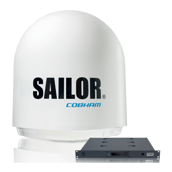
-
Contents
-
Table of Contents
-
Troubleshooting
-
Bookmarks
Related Manuals for COBHAM SAILOR 900 VSAT
Summary of Contents for COBHAM SAILOR 900 VSAT
-
Page 1
SAILOR 900 VSAT Technical manual… -
Page 3
SAILOR 900 VSAT Technical manual Document number: 98-133966-G1 Release date: 16 September 2013… -
Page 4
50 to: SW Technology/GPL Compliance, Thrane & Thrane A/S, Lundtoftegaardsvej 93D 2800 Lyngby DENMARK Please write «source for product SAILOR 900 VSAT» in the memo line of your payment. This offer is valid to anyone in receipt of this information. 98-133966-G1… -
Page 5: Safety Summary
Failure to comply with these precautions or with specific warnings elsewhere in this manual violates safety standards of design, manufacture and intended use of the equipment. Cobham SATCOM assumes no liability for the customer’s failure to comply with these requirements.
-
Page 6
Power supply The voltage range for the SAILOR 900 VSAT is 20 — 32 VDC. Note that the Above Deck Unit is powered by the ACU. If a 24 VDC power bus is not available, an external 115/230 VAC to 28 VDC power supply can be used, for example a SAILOR 6080 Power Supply. -
Page 7
CAUTION! Do not manually turn the Polarisation Unit of the antenna, it may cause damage to the antenna. If needed to turn the Polarisation Unit manually, remove the connector (1) marked M of the Polarisation Motor Module (2). Remove 98-133966-G1… -
Page 8
VSAT restrictions There are restrictions in use of the frequency band 13.75 to 14 GHz in the Note following countries: • Belgium • Hungary • Latvia • Malta • Slovakia Contact VSAT modem provider for local setups. 98-133966-G1… -
Page 9: Table Of Contents
Power supply (optional) ………………..2-8 2.1.7 Service activation ……………………2-8 Part numbers and options ………………2-9 2.2.1 Applicable Thrane & Thrane model and part numbers ……..2-9 2.2.2 Options for SAILOR 900 VSAT ………………2-9 Chapter 3 Installation Unpacking ……………………..3-1 3.1.1 What’s in the box ……………………3-1 3.1.2 Initial inspection ……………………3-2…
-
Page 10
Installation of the VMU ……………….3-25 3.5.1 General mounting considerations — VMU …………3-25 Installing the dual-antenna mode (optional) ……….3-26 Chapter 4 Interfaces Interfaces of the SAILOR 900 VSAT ACU ………….4-1 4.1.1 LEDs, display and keypad ………………..4-1 4.1.2 ACU connector panel — overview …………….4-1 4.1.3 DC Input connector ………………….4-2… -
Page 11
6.2.3 Flow chart for azimuth and cable calibration …………6-9 6.2.4 Line up procedure ………………….6-10 6.2.5 SAILOR 900 VSAT fixed TX gain principle …………6-12 Configuration with the web interface …………6-13 6.3.1 Overview and dashboard ………………..6-13 6.3.2 Satellite profiles and VSAT modem profiles …………6-19 6.3.3… -
Page 12
Table of contents Software update ……………………8-5 8.2.1 Hardware and software requirements ……………8-5 8.2.2 Software update (ADU and ACU) …………….8-5 8.2.3 Verifying the software update ………………8-8 Status signalling with LEDs and status messages ……..8-9 8.3.1 Overview ……………………..8-9 8.3.2 LEDs of the ADU modules ………………..8-10 8.3.3 LEDs in the ACU ……………………8-10 Removal and replacement of the ACU …………8-11… -
Page 13
Table of contents Returning units for repair ………………8-114 Appendix A Technical specifications SAILOR 900 VSAT system components …………A-1 A.1.1 General specifications …………………. A-1 A.1.2 ADU ……………………….A-2 A.1.3 ACU ……………………….A-4 A.1.4 Supported VSAT modems ………………… A-5 A.1.5 Patents ……………………….. A-5 Outline drawings …………………. -
Page 14
Table of contents Gilat SkyEdge II VSAT modem …………….C-21 C.5.1 Interfaces and VSAT modem configuration …………C-21 C.5.2 ACU configuration ………………….C-22 C.5.3 Configuration example (Gilat SkyEdge II ) …………C-23 Inmarsat G5 modem ………………..C-24 C.6.1 Interfaces and VSAT modem configuration …………C-24 C.6.2 Connecting a Inmarsat G5 modem ……………..C-24 C.6.3 Configuration example (Inmarsat G5) …………..C-24… -
Page 15
Table of contents Alternative grounding for aluminum hulls …………F-6 F.4.1 Grounding the ACU ………………….F-6 F.4.2 Grounding the ADU ………………….F-6 Alternative grounding for fibre glass hulls …………F-8 F.5.1 Grounding the ACU ………………….F-8 F.5.2 Grounding the ADU ………………….F-9 Separate ground cable ………………..F-10 F.6.1 Ground cable — construction ………………F-10 F.6.2… -
Page 16
Table of contents 98-133966-G1… -
Page 17: List Of Figures
Above Deck Unit modules 1/2 ……………………2-4 Figure 2-4: Above Deck Unit modules 2/2 ……………………2-5 Figure 2-5: SAILOR 900 VSAT ACU, connector overview ………………2-7 Figure 2-6: SAILOR 900 VSAT ACU, 19” rack version………………..2-7 Figure 2-7: Antenna Control Unit for 19” rack installation ……………….2-8…
-
Page 18
ACU display after first power on (example with LAN ports 1 and 4 used)……5-5 Chapter 6 Configuration Figure 6-1: LAN connector used for configuring the SAILOR 900 VSAT …………6-2 Figure 6-2: SAILOR 900 VSAT Dashboard……………………6-2 Figure 6-3: Service profile for calibration ……………………6-4 Figure 6-4: Web interface: SERVICE, Calibration …………………..6-5… -
Page 19
Web interface: HELPDESK, Event list………………….8-3 Figure 8-3: LAN connector used for software update (TMA) …………….8-5 Figure 8-4: SAILOR 900 VSAT connected: Software update with the TMA……….8-6 Figure 8-5: LAN connector used for software update (web interface)…………8-7 Figure 8-6: Software update with the web interface ………………..8-7 Figure 8-7: Verifying software update ……………………..8-8… -
Page 20
List of figures Figure 8-22: Block diagram – S-bus……………………..8-24 Figure 8-23: GPS module………………………….8-25 Figure 8-24: Switch off the power to the antenna ………………..8-26 Figure 8-25: GPS module facing the service hatch………………..8-26 Figure 8-26: Connector for GPS PCB ……………………..8-27 Figure 8-27: Screws on GPS module ……………………..8-27 Figure 8-28: VSAT Interface Module (VIM)…………………….8-28… -
Page 21
List of figures Figure 8-63: Azimuth motor, tighten the belt tensioner………………8-52 Figure 8-64: Azimuth encoder, remove cover………………….8-53 Figure 8-65: Azimuth DDM, disconnect connector………………..8-53 Figure 8-66: Azimuth encoder, remove……………………..8-54 Figure 8-67: Azimuth encoder, adjust belt tension………………..8-54 Figure 8-68: Azimuth Encoder, adjust belt tension………………..8-55 Figure 8-69: Azimuth motor, tighten the belt tensioner………………8-55 Figure 8-70:… -
Page 22
Block Up Converter (BUC)……………………..8-85 Figure 8-116: BUC, removing…………………………8-85 Figure 8-117: BUC, removing (continued)……………………8-86 Figure 8-118: Low Noise Block (LNB) (SAILOR 900 VSAT var. A)……………..8-87 Figure 8-119: LNB, removing (SAILOR 900 VSAT variant A) ………………8-88 Figure 8-120: LNB, removing (continued)……………………8-88 Figure 8-121: Ortho Mode Transducer (OMT)…………………..8-89… -
Page 23
List of figures Figure 8-145: Second signal test: X-pol LNB / low band………………8-111 Figure 8-146: Third signal test: Co-Pol LNB / high band………………8-112 Figure 8-147: Fourth signal test: X-Pol LNB / high band………………8-113 App. A Technical specifications Figure A-1: Outline drawing: ADU……………………….. -
Page 24
List of figures App. F Grounding and RF protection Figure F-1: Extending the ground plane……………………. F-2 Figure F-2: Grounding the ADU……………………….F-3 Figure F-3: Grounding at a dedicated RF ground (alternative)…………….F-5 Figure F-4: Alternative grounding for aluminium hulls……………….. F-7 Figure F-5: Alternative grounding for fibreglass hulls……………….. -
Page 25
Table 2-1: Model and part numbers for the SAILOR 900 VSAT system…………2-9 Table 2-2: Model and part numbers for options of the SAILOR 900 VSAT system ……..2-9 Chapter 3 Installation Table 3-1: Maximum distance from the ship’s motion center versus ship’s roll period……3-7 Table 3-2: Mast dimensions without braces………………….3-11… -
Page 26
List of tables Table 6-7: Web interface, DASHBOARD, POINTING parameter …………..6-18 Table 6-8: Web interface, DASHBOARD, TX parameter ………………6-18 Table 6-9: Elevation cutoff (in degrees) versus VSAT modem bandwidth and power …….6-22 Table 6-10: Setup of LAN connectors ………………………6-29 Table 6-11: Statistics report, header record …………………..6-33 Table 6-12: Parameters recorded in a statistics report………………6-33… -
Page 27
List of tables Table C-5: RS-232 Console cable for iDirect Serial VSAT modem …………..C-13 Table C-6: Requirements for VSAT modem option file, Serial …………….C-14 Table C-7: Configuration of Gilat SkyEdge II VSAT modem…………….C-22 App. D Command line interface Table D-1: Command typography……………………… -
Page 28
List of tables xxvi 98-133966-G1… -
Page 29: Chapter 1 About This Manual
About this manual Intended readers This is an installation and service manual for the SAILOR 900 VSAT system, intended for installers of the system and service personnel. Personnel installing or servicing the system must be properly trained and authorized by Cobham SATCOM.
-
Page 30: Typography
Typography Typography In this manual, typography is used as indicated below: Bold is used for the following purposes: • To emphasize words. Example: “Do not touch the antenna”. • To indicate what the user should select in the user interface. Example: “Select SETTINGS >…
-
Page 31: Chapter 2 Introduction
SAILOR 900 VSAT system 2.1.1 Overview The SAILOR 900 VSAT is a unique stabilized maritime VSAT antenna system operating in the Ku-band (10.7 to 14.5 GHz). It provides bi-directional IP data connections both on regional satellite beams and quasi-global Ku-band satellite networks.
-
Page 32
SAILOR 900 VSAT system 2..1.1.1 SAILOR 900 VSAT features Single 50 Ohm coax cable for the ADU. Support of several VSAT modems. Dual antenna mode. SNMP support. Service communication using SAILOR FleetBroadband over WAN. … -
Page 33: Above Deck Unit (Adu)
2.1.2 Above Deck Unit (ADU) The SAILOR 900 VSAT ADU is a 103 cm VSAT stabilised tracking antenna, consisting of a suspended antenna with a standard global RF configuration. The ADU’s weight is130 kg (Var. A) or 126,5 kg (Var. B). It is stabilized by heavy duty vibration dampers in 3-axis (plus skew) and can be used in environments with elevations of -25°…
-
Page 34
SAILOR 900 VSAT system 2..1.2.1 Modules in the SAILOR 900 VSAT ADU Figure 2-3: Above Deck Unit modules 1/2 1. GPS module. 2. VSAT Interface Module (VIM). 3. Pedestal Control Module (PCM). 4. Service switch. 5. DC-Motor Driver Module for cross elevation (DDM). -
Page 35: Chapter 2 Introduction
SAILOR 900 VSAT system 11.Polarisation motor. 12.Polarisation encoder. 13.Block Up Converter (BUC). 14.Low Noise Block downconverter (x2), (LNB). 15.Ortho Mode Transducer (OMT) (not visible on photo). 16.Inertial Sensor Module (ISM). 17.Elevation locking pin to lock the antenna dish in a fixed position.
-
Page 36: Antenna Control Unit (Acu)
SAILOR 900 VSAT system 2..1.2.2 SAILOR 900 VSAT ADU interface All communication between the ADU and the ACU passes through a single standard 50 Ohm cable (with N connector) through the rotary joint. No cable work is required inside the radome.
-
Page 37: Figure 2-5: Sailor 900 Vsat Acu, Connector Overview
The ACU has additionally a LAN connector at the front for accessing the service port from the ACU front panel. Service port Figure 2-6: SAILOR 900 VSAT ACU, 19” rack version 2..1.3.2 Installation friendly The ACU comes in a 19” rack version.
-
Page 38: Vsat Modem Unit (Vmu)
For a list of supported VSAT modems see the SAILOR 900 VSAT data sheet at cobham.com/satcom. 2.1.5 Satellite type approvals For a list of satellite type approvals see the SAILOR 900 VSAT data sheet at cobham.com/satcom. 2.1.6 Power supply (optional) Use the SAILOR 6080 AC/DC Power Supply to provide DC power to the SAILOR 900 VSAT.
-
Page 39: Part Numbers And Options
Antenna cable 50 m, N-Conn (not mounted), male/male 407090A-925 Pigtail Cable 1.25 m, N-Conn, female/male 407090-010 Accessory kit for dual antenna mode Table 2-2: Model and part numbers for options of the SAILOR 900 VSAT system 98-133966-G1 Chapter 2: Introduction…
-
Page 40
Part numbers and options 2-10 Chapter 2: Introduction 98-133966-G1… -
Page 41: Installation
Unpacking 3.1.1 What’s in the box 3..1.1.1 Unpack your SAILOR 900 VSAT ADU and check that the following items are present: • ADU with 4 lifting brackets (already mounted) • Package with bolts, washers and cable glands (2 sizes) 3..1.1.2…
-
Page 42: Initial Inspection
Unpacking 3.1.2 Initial inspection Inspect the shipping cartons and wooden box immediately upon receipt for evidence of damage during transport. If the shipping material is severely damaged or water stained, request that the carrier’s agent be present when opening the cartons and wooden box. Save all box packing material for future use.
-
Page 43: Site Preparation
General site considerations For optimum system performance, some guidelines on where to install or mount the different components of the SAILOR 900 VSAT System must be followed. It is recommended to mount the ADU in a location with as much 360°…
-
Page 44: Obstructions (Adu Shadowing)
Site preparation 3.2.2 Obstructions (ADU shadowing) Place the ADU so that it has as much free line-of-sight without any structures in the beam through one full 360 degrees turn of the vessel. Do not place the ADU close to large objects that may block the signal. To avoid obstruction elevate the ADU by mounting it on a mast or on a mounting pedestal on a deck or deck house top.
-
Page 45: Blocking Zones — Azimuth And Elevation
Figure 3-2: 2 blocking zones with no-transmit zones, azimuth (example) Figure 3-3: Blocking zone with no-transmit zones, elevation angle (example) The blocking zones are set up in the SAILOR 900 VSAT built-in web interface of the ACU. For further information see Setting up blocking zones (RX and TX) on page 6-26.
-
Page 46: Safe Access To The Adu: Radiation Hazard
Safe access to the ADU: Radiation hazard The SAILOR 900 VSAT ADU radiates up to 49 dBW EIRP. This translates to a minimum safety distance of 30 m from the ADU while it is transmitting, based on a radiation level of 10 W/m…
-
Page 47: Ship Motion And Offset From The Ship’s Motion Centre
Site preparation 3.2.5 Ship motion and offset from the ship’s motion centre Even though it is recommended to mount the ADU high, keep the distance between the ADU and the ship’s motion centre as short as possible. The higher up the ADU is mounted, the higher is the linear g force applied to the ADU.
-
Page 48: Adu Mast Design: Foundation And Height
Site preparation 3.2.6 ADU mast design: Foundation and height The ADU mast must be designed to carry the weight of the ADU unit, which is 130 kg (Var. A) or 126,5 kg (Var. B) (+ the weight of the mast flange).
-
Page 49: Figure 3-8: Adu Mast Flange, Distance To The Welded Seam
Site preparation Figure 3-8: mast flange, distance to the welded seam CAUTION! Avoid sharp edges where the flange is in direct contact with the radome. Round all edges as much as possible to avoid damaging the surface of the radome. Figure 3-9: ADU, bottom view 98-133966-G1 Chapter 3: Installation…
-
Page 50: Figure 3-10: Free Mast Length And Bracing For A Tall Mast
Site preparation 3..2.6.2 Mast length and diameter The placement of the ADU must ensure a rigid structural connection to the hull or structure of the ship. Parts of the ship with heavy resonant vibrations are not suitable places for the ADU. A small platform or short mast shall provide rigid support for the ADU fastening bolts and a rigid interface to the ship.
-
Page 51: Table 3-2: Mast Dimensions Without Braces
3..2.6.3 SAILOR 900 VSAT ADU mast length The below tables show the minimum dimensions for a SAILOR 900 VSAT ADU mast with and without stays or wires. Note that the values are only guidelines — always consider the environment and characteristics of the ship before deciding on the mast dimensions.
-
Page 52: Interference
The ADU must be mounted as far away as possible from the ship’s radar and high power radio transmitters, because they may compromise the ADU performance. RF emission from radars might actually damage the ADU. The SAILOR 900 VSAT ADU itself may also interfere with other radio systems. 3..2.7.1 Radar…
-
Page 53: Figure 3-11: Interference With The Vessel’s Radar
(below approximately 10 m) between radar antenna and the SAILOR 900 VSAT ADU. Therefore it is recommended to ensure as much vertical separation as possible when the SAILOR 900 VSAT ADU has to be placed close to a radar antenna.
-
Page 54: Table 3-6: Minimum Radar Separation, S-Band
Radar interference Even at distances greater than “d min.” in the previous section the radar might still be able to degrade the performance of the SAILOR 900 VSAT system. The presence of one or more S or X-band radars within a radius up to 100 m may cause a minor degradation of the Ku-band connection.
-
Page 55: Figure 3-12: Recommended Distance To Transmitters (M) For Frequencies Below 1000 Mhz
Site preparation 3..2.7.4 GPS receivers Good quality GPS receivers will work properly very close to the ADU — typically down to one meter outside the main beam. 3..2.7.5 Other transmitters See the following figure for minimum recommended distance to transmitters in the frequency range below 1000 MHz. Figure 3-12: Recommended distance to transmitters (m) for frequencies below 1000 MHz 98-133966-G1…
-
Page 56: Other Precautions
Site preparation 3.2.8 Other precautions 3..2.8.1 Condensation and water intrusion If possible, install the radome such that direct spray of seawater is avoided. In some weather conditions there may occur condensation inside the radome. The drain tube is designed to lead any water away from inside the radome.
-
Page 57: Installation Of The Adu
Installation of the ADU Installation of the ADU The ADU is shipped fully assembled. You have to install it on the mast and attach the ADU cable. WARNING! Use a strong webbed sling with a belt to lift the ADU without damaging the radome. Make sure that the sling can carry the ADU’s weight130 kg, 287 lbs (Var.
-
Page 58: Installing The Adu
Figure 3-15: Free space for access to the service hatch The ADU does not have to be aligned with the bow-to-stern line of the ship. When configuring the SAILOR 900 VSAT you make an azimuth calibration to obtain the correct azimuth of the ADU.
-
Page 59: Figure 3-16: Adu Installation, Webbed Sling Attached To The 4 Lifting Brackets
Installation of the ADU Figure 3-16: ADU installation, webbed sling attached to the 4 lifting brackets 5. Attach 2 tag lines of suitable length to 2 lifting brackets and man them. 6. With a crane lift the ADU off the wooden platform and move it on top of the ADU mast.
-
Page 60: Figure 3-18: Connecting The Adu Cable
Installation of the ADU 9. Put the coaxial ADU cable through the protection plate as shown in the following figure, and connect the N connector of the ADU cable to the ADU. Select a suitable size for the cable gland: 16—20 mm diameter or 19—23 mm diameter.
-
Page 61: Opening And Removing The Service Hatch
Installation of the ADU 3..3.1.1 Maximum allowed RF loss in the ADU cable Maximum allowed cable loss 20 dB at 1950 MHz. This is to ensure optimum performance of the system. 3.3.2 Opening and removing the service hatch Open the hatch to access the antenna modules. The two latches of the service hatch must be locked by fastening the two screws in the latches with a Torx TX20 screw driver to protect the ADU modules against unauthorised access.
-
Page 62: Grounding The Adu
Installation of the ADU 3.3.3 Grounding the ADU The ADU must be grounded using the mounting bolts. If the ADU cannot or should not be electrically connected directly to the mounting surface, you can use a separate grounding cable to make the connection between the ADU and the common ground to which the ACU is also connected.
-
Page 63: Alternative Adu Cable
Installation of the ADU 3.3.4 Alternative ADU cable The maximum allowed RF-loss in the ADU cable must be 20 dB at 1950 MHz and 0.9 Ohm DC. This is to ensure the performance of the system. Preferably choose one of the cable types listed in the table below.
-
Page 64: Installation Of The Acu
Make sure that the unit is mounted securely according to the requirements for your 19” rack. 3. Connect all cables. See Interfaces of the SAILOR 900 VSAT ACU on page 4-1 for a description of the ACU connectors.
-
Page 65: Grounding The Acu
Figure 3-24: ACU, 19” rack version, ground stud Installation of the VMU For a list of supported VSAT modems see the SAILOR 900 VSAT data sheet or Figure 6-16: Web interface: SETTINGS, VSAT modem profile – supported modems.
-
Page 66: Installing The Dual-Antenna Mode (Optional)
Installing the dual-antenna mode (optional) You can use the SAILOR 900 VSAT in dual antenna mode with 2 ADUs, 2 ACUs and the dual-antenna accessories kit. The kit consists of two 75 Ohm RF cables, an RF splitter and an RF combiner. In case one antenna enters a blocking zone, the other antenna of the dual-antenna system takes over and the system continues working.
-
Page 67: Figure 3-26: Dual Mode Antenna, Connecting Cables (Example)
Installing the dual-antenna mode (optional) 3. Provide vessel heading input to the master ACU and slave ACU, see NMEA 0183 connector (RS-422) on page 4-4. 4. Connect the cables as shown below and in the table below. Figure 3-26: Dual mode antenna, connecting cables (example) Connect cables Purpose Master ACU LAN to Slave ACU LAN…
-
Page 68
Installing the dual-antenna mode (optional) 3-28 Chapter 3: Installation 98-133966-G1… -
Page 69: Interfaces
Chapter 4 Interfaces This chapter is organised in the following sections: • Interfaces of the SAILOR 900 VSAT ACU • Interfaces of the VMU Interfaces of the SAILOR 900 VSAT ACU 4.1.1 LEDs, display and keypad Figure 4-1: ACU — LEDs, display and keypad Figure 4-2: ACU: LEDs, display and keypad (detailed) 4.1.2…
-
Page 70: Dc Input Connector
Interfaces of the SAILOR 900 VSAT ACU The connector LAN on the front panel is typically connected to the service port at LAN3 with a straight Ethernet cable. Then you can access the service port from the front of the ACU rack version.
-
Page 71: Adu Connector
Interfaces of the SAILOR 900 VSAT ACU 4.1.4 ADU connector There is just one cable from the ACU to the ADU. This is used to power the ADU, supply 10 MHz clock, handle all communication between ACU and ADU, and deliver the VSAT Rx and Tx signals.
-
Page 72: Nmea 0183 Connector (Rs-422)
Interfaces of the SAILOR 900 VSAT ACU 4.1.6 NMEA 0183 connector (RS-422) Connect the ship’s gyro to this connector. Wire Outline (on the ACU) Pin function number color Not connected — NET-H (NMEA 2000) White NET-L (NMEA 2000) Blue NET-S (NMEA 2000)
-
Page 73: And Rs-422 Connectors
Interfaces of the SAILOR 900 VSAT ACU Recommended NMEA 0183 cable: Two-wire constructed with one enclosed shield Network signal pair: • Size: No. 24 AWG (0.24 sq. mm) or heavier • Characteristic impedance: 95 — 140 Ohm • Propagation delay: 5 nanoseconds per meter, maximum •…
-
Page 74: Lan1, Lan2, Lan3 And Lan4 Connectors
Interfaces of the SAILOR 900 VSAT ACU Outline (on the ACU) Pin function number Ground Line A RXD (+) Line B TXD (-) Ground Ground Not connected Line A RXD (-) Line B TXD (+) Not connected Table 4-6: RS-422 connector, male, outline and pin assignment 4.1.8…
-
Page 75: Table 4-7: Ethernet Connector, Outline And Pin Assignment
Interfaces of the SAILOR 900 VSAT ACU Outline Pin function Wire color number White/orange Orange White/green Not connected Blue Not connected White/blue Green Not connected White/brown Not connected Brown Table 4-7: Ethernet connector, outline and pin assignment Cable type: CAT5, shielded.
-
Page 76: Interfaces Of The Vmu
Interfaces of the VMU Interfaces of the VMU For interfaces of the VMU and how to connect a VMU correctly to the ACU see the following sections and the user documentation of the VMU. For step-by-step guidelines how to set up the VSAT modem see Appendix C, VMU settings.
-
Page 77: Connecting An Evolution® Satellite Router
Interfaces of the VMU 4.2.2 Connecting an Evolution® Satellite Router Connect the VSAT modem to the ACU as shown in the figure below: Figure 4-7: Connecting an Evolution Satellite Router Cable 3 is only used when using OpenAMIP protocol. Note For cables see Table 4-8: Cables to connect an iNFINITI®…
-
Page 78: Connecting A Satlink 2900 Vsat Modem
Interfaces of the VMU 4.2.4 Connecting a Satlink 2900 VSAT modem Connect the VSAT modem to the ACU as shown in the figure below: Figure 4-9: Connecting a SatLink 2900 Modem Cable Description Cable specifications RX Out to Rx 75 Ohm coax cables F-F (1m) and adapter F to N 50 Ohm, included LAN1 to LAN Standard Ethernet cable…
-
Page 79: Chapter 5 Connecting Power
Chapter 5 Connecting power This chapter is organised in the following sections: • Power source • Power cable selection • Connecting power • Power up Power source There are different options for the power supply: • The 24 VDC ship supply provides power for the ACU. •…
-
Page 80: Power Cable Selection
Power cable selection Power cable selection 5.2.1 Source impedance The maximum length of the power cable depends on the type of cable used and the source impedance of the DC power installation in the ship. The maximum allowed source impedance depends on the usage of the power range of the terminal DC input (Start up voltage: 22 VDC guaranteed, operating range: 20 –…
-
Page 81: Power Cable Recommendations
Power cable selection 5.2.3 Power cable recommendations 5..2.3.1 Overview The ACU is delivered with a power connector (PCB plug-in connector, female plug, Weidmuller, Part number 1930050000), which accepts wires up to AWG10/6 mm • When installing the power cable, install positive and negative supply wires closely together side by side to keep cable inductance low.
-
Page 82: Connecting Power
Connecting power Connecting power 5..3.0.1 To connect the power cable to the ACU 1. Connect the positive and negative input terminals to the ship’s DC supply according to the recommendations in the previous sections. 2. Connect the power plug to DC Input. For information on pin-out, see DC Input connector on page 4-2.
-
Page 83: Power Up
• READY This may take some time (up to a couple of minutes). 3. The SAILOR 900 VSAT is ready to be calibrated (for first time power up) or receive data from the VSAT modem (when in normal operation). The ACU display shows the following message:…
-
Page 84: Initialisation Steps In Daily Use
• ADU POST • READY • POINTING ANTENNA • ACQUIRING SIGNAL • TRACKING 5.4.3 SAILOR 900 VSAT operational When the display shows TRACKING and the LED Logon is steady green, the system is operational. Chapter 5: Connecting power 98-133966-G1…
-
Page 85: Configuration
6.1.1 Overview Use the built-in web interface of the SAILOR 900 VSAT ACU to make a full configuration of the SAILOR 900 VSAT with the correct VMU, the satellite positions you intend to use and other parameters. Connect the LAN cable to LAN 3 on the rear panel or the front LAN connector of the ACU.
-
Page 86: Figure 6-1: Lan Connector Used For Configuring The Sailor 900 Vsat
Figure 6-2: SAILOR 900 VSAT Dashboard When the Dashboard is displayed you have verified that the connection to the SAILOR 900 VSAT can be established. The web interface is ready for use. You can continue to configure the system. If you cannot establish a connection there might be problems with the Proxy server settings of your PC.
-
Page 87: Calibration Of The Sailor 900 Vsat
• Vessel heading & calibration of azimuth and cable • Flow chart for azimuth and cable calibration • Line up procedure • SAILOR 900 VSAT fixed TX gain principle 6.2.1 Setup of a service profile for calibration To prepare for calibration you can set up a service profile for calibration.
-
Page 88: Figure 6-3: Service Profile For Calibration
Calibration of the SAILOR 900 VSAT Figure 6-3: Service profile for calibration 3. Enter the data for the satellite that you want to use as a calibration reference. You can enter the satellite data manually or select a satellite from the list of predefined satellites (Eutelsat). For satellite information see DVB-S satellites on page E-1 or www.lyngsat.com.
-
Page 89: Vessel Heading & Calibration Of Azimuth And Cable
Calibration of the SAILOR 900 VSAT LNB: Co-pol or X-pol, use this for test if both the LNBs and RX cables function properly in case of issues with the reception of a signal. The polarisation must remain the same as stated for the transponder used for the azimuth calibration.
-
Page 90
Calibration of the SAILOR 900 VSAT 6.2.2.1 Fixed heading Do not use fixed heading for vessels! Use fixed heading only for fixed installations like remote areas or oil rigs, during training and test. You can enable fixed heading and enter the fixed heading in degrees. -
Page 91: Figure 6-5: Web Interface: Service, Calibration, Cable Attenuator Margin
Calibration of the SAILOR 900 VSAT This screen shows how much attenuation margin that is left for the antenna cable. This indicates whether the antenna cable and connectors are in good condition and well crimped. Figure 6-5: Web interface: SERVICE, Calibration, cable attenuator margin It is recommended to make a cable calibration when servicing the system to check if the antenna cable is still in good order.
-
Page 92: Table 6-3: Possible Error Codes During Calibration
RF setup error, e.g. missing or invalid TX frequency. Invalid satellite, e.g. satellite not visible. Table 6-3: Possible error codes during calibration The SAILOR 900 VSAT is calibrated now. If the calibration failed there will be a message on the calibration screen. Chapter 6: Configuration…
-
Page 93: Flow Chart For Azimuth And Cable Calibration
Calibration of the SAILOR 900 VSAT 6.2.3 Flow chart for azimuth and cable calibration The following flow chart gives an example of an azimuth and cable calibration. Figure 6-6: Example for azimuth and cable calibration — step by step 98-133966-G1…
-
Page 94: Line Up Procedure
The ship must not move during the calibration procedure. Note The SAILOR 900 VSAT has been tested at factory online on a live satellite link to calibrate the TX polarisation unit. You can fine-tune the TX polarization by doing a line up as described below. To do the line up, do as follows: 1.
-
Page 95: Figure 6-8: Web Interface: Service, Line Up: Antenna Ready
Calibration of the SAILOR 900 VSAT 4. Click the button Activate and wait until the status field shows Antenna ready. Follow the instructions from your service provider. Figure 6-8: Web interface: SERVICE, Line up: Antenna ready 5. Enter the Modem CW frequency (Continuous Wave) in GHz.
-
Page 96: Sailor 900 Vsat Fixed Tx Gain Principle
• Utilization of the full 8W BUC power over frequency • P1dB compression point the same over frequency When installing the SAILOR 900 VSAT you make a cable calibration. At that point every installation finds the same P1dB compression setting regardless of cable length.
-
Page 97: Configuration With The Web Interface
Configuration with the web interface Configuration with the web interface 6.3.1 Overview and dashboard 6.3.1.1 Topics in the web interface Use the site map to get an overview over the existing menus, submenus and topics. You can click on each menu in the site map to go directly to the page or display the respective submenu.
-
Page 98: Figure 6-11: Web Interface: Dashboard
Configuration with the web interface 6.3.1.2 Dashboard and navigation The Dashboard is the first screen that is displayed when the user or administrator enters the IP address of the web interface of the ACU. The Dashboard is used for viewing properties and status of the ACU and ADU.
-
Page 99: Table 6-4: Web Interface: Event Icon
Configuration with the web interface 6.3.1.3 Icons in the icon bar The following icons may appear in the icon bar in the web interface: Icon Explanation An event is active. Click the icon to see a list of active events. For explanations of the event messages, see Event list on page 8-3 and Event messages –…
-
Page 100
Configuration with the web interface 6.3.1.5 Proxy server settings in your browser If you are connecting your computer using a LAN or WLAN interface, the Proxy server settings in your browser must be disabled before accessing the web interface. Most browsers support disabling of the Proxy server settings for one specific IP address, so you can disable Proxy server settings for the web interface only, if you wish. -
Page 101: Table 6-5: Web Interface, Dashboard, Sailor 900 Vsat Parameters
ADU part name, version of the SAILOR 900 VSAT. ACU serial number, ADU serial number, Software version Table 6-5: Web interface, DASHBOARD, SAILOR 900 VSAT parameters a. Can be altered when using a generic modem profile. 98-133966-G1 Chapter 6: Configuration 6-17…
-
Page 102: Table 6-6: Web Interface, Dashboard, Vsat Modem Parameter
The BUC TX information is displayed on the DASHBOARD. The BUC TX indicates if the SAILOR 900 VSAT VSAT has enabled the BUC or not. It can show BUC Tx On or Off. This information is also shown in the display of the ACU as TX ON or TX OFF.
-
Page 103: Satellite Profiles And Vsat Modem Profiles
The SAILOR 900 VSAT shows BUC TX On when the following conditions are met: • The SAILOR 900 VSAT must sense the 10 MHz Tx reference signal from the connected VSAT modem. • The VSAT modem must have Rx lock.
-
Page 104: Figure 6-13: Web Interface: Settings — List Of Satellite Profiles (Example)
Configuration with the web interface You must add at least one VSAT modem profile before you Note can add a satellite profile. See VSAT modem profile – New entry and Edit on page 6-23. 6.3.2.2 Satellite profiles – New entry and Edit Figure 6-13: Web interface: SETTINGS — list of satellite profiles (example) Each satellite profile has one assigned VSAT modem profile.
-
Page 105: Figure 6-14: Web Interface: Settings, Satellite Profiles — New Entry (Example)
Configuration with the web interface Figure 6-14: Web interface: SETTINGS, Satellite profiles — new entry (example) To add or edit a satellite profile, do as follows: 1. Go to SETTINGS or Satellite profiles and click Edit or New entry. 2. Enter or edit the Satellite profile name. It is helpful to assign a name containing the location where the Satellite profile Note is to be used (e.g.
-
Page 106: Table 6-9: Elevation Cutoff (In Degrees) Versus Vsat Modem Bandwidth And Power
Configuration with the web interface 6. At Elevation cutoff enter the minimum elevation angle for the antenna to function in accordance with ETSI (ETSI EN 302 340) and FCC (FCC §25.205) regulations. • ETSI (ETSI EN 302 340): The minimum elevation angle depends on the Tx bandwidth and the nominal power of the VSAT modem, see the table below.
-
Page 107: Figure 6-15: Web Interface: Settings, Vsat Modem Profiles — List (Example)
Configuration with the web interface 6.3.2.3 VSAT modem profiles A VSAT modem profile contains all VSAT modem settings that are necessary for a successful connection to the satellite. The data you have to fill in are provided by your VSAT service and modem provider. You must add at least one VSAT modem profile.
-
Page 108
Select the VSAT modem baud rate and whether you want to use the 10 MHz reference from the ACU or the VSAT modem. The SAILOR 900 VSAT can work either using the Rx or Tx 10 MHz Important reference signals provided by the modem or using its own built-in 10 MHz reference signal. -
Page 109: Figure 6-17: Satellite Profile For Generic Modem
Configuration with the web interface For a generic modem you enter all parameters in the satellite profile. Figure 6-17: Satellite profile for generic modem 98-133966-G1 Chapter 6: Configuration 6-25…
-
Page 110: Setting Up Blocking Zones (Rx And Tx)
Configuration with the web interface 6.3.3 Setting up blocking zones (RX and TX) On this page you define blocking zones, i.e. NO TX and RX zones, enter azimuth values and elevation angles for each blocking zone. You must select Active to enable a blocking zone. Figure 6-18: Web interface: SETTINGS, Blocking zones —…
-
Page 111: Figure 6-19: Blocking Zone, Example: 315 — 45 Degrees
Configuration with the web interface 3. Azimuth: Enter start and stop azimuth value in degrees for the blocking zone. Values allowed: 0 to 360 degrees. Enter clockwise. Figure 6-19: Blocking zone, example: 315 — 45 degrees Figure 6-20: Blocking zone, example: 45 — 315 degrees 4.
-
Page 112: Configuring The Lan Network
Configuration with the web interface 6.3.4 Configuring the LAN network You can enter a host name. The host name helps identifying the SAILOR 900 VSAT system when sending e-mail reports. The ACU has four 10/100 Mbit Ethernet ports labelled LAN port 1, 2, 3 and 4. The ports are divided in three groups, each group operating in its own network.
-
Page 113: Table 6-10: Setup Of Lan Connectors
Configuration with the web interface Sections Preferred use NETWORK The host name is used for identifying the ACU in local Host name networks and in e-mail reports. The default host name is acu. You can change the name. Letters (a-z), digits (0-9) and hyphen (-) are allowed as legal characters.
-
Page 114
Configuration with the web interface The DHCP start and end addresses must be on the same network as the port’s static IP. 6.3.4.3 DNS setup If you have access to a Domain Name Server (DNS) you can specify the address of the e-mail server by using the server name instead of its IP address. -
Page 115: E-Mail Setup
Configuration with the web interface 6.3.5 E-mail setup To be able to send diagnostics and statistics reports using e-mail you must set up a couple of parameters. Contact your IT department for the specific data. To configure the e-mail setup, do the following: 1.
-
Page 116: Sending Statistics Reports
6.3.6 Sending statistics reports SAILOR 900 VSAT can send a statistics report at fixed intervals. This report contains historical information from the SAILOR 900 VSAT of up to 1 month. It is sent as a zipped attachment to an e-mail. The file format is a comma separated value file (csv).
-
Page 117: Table 6-11: Statistics Report, Header Record
ACU serial number ADU SN ADU serial number SW ver. Software version System type SAILOR 900 VSAT Table 6-11: Statistics report, header record Parameter recorded Description UTC. (s) UTC in seconds and date format for the data set. UTC (YYYY-MM-DD hh:mm) RSSI.Av…
-
Page 118: Figure 6-24: Statistics — How To Read Data For A Range
Configuration with the web interface Parameter recorded Description Carrier rf.rx (GHz) Rx frequency of carrier for this record. Carrier rf.tx (GHz) Tx frequency of carrier for this record. Rx Lock (%) Rx locked and logon time, in percent, for the sampling Logon (%) interval.
-
Page 119: Sending A Diagnostics Report
Configuration with the web interface The following figure shows an example of a statistics report in MS Excel 2007. Figure 6-25: Statistics report (example) 6.3.7 Sending a diagnostics report You can send automatically generated diagnostic reports at fixed intervals. The diagnostic report contains information relevant for the service personnel during troubleshooting.
-
Page 120: Dual Antenna Mode (Optional)
Table 6-12 on page 33. 6.3.8.1 Configuring the Master ACU The Master ACU is configured exactly the same way as a stand-alone SAILOR 900 VSAT system with satellite profiles and VSAT modem profiles. Do as follows: 1. Go to SETTINGS > Dual antenna. 6-36…
-
Page 121: Figure 6-27: Enabling Dual-Antenna Mode In Master Acu
Configuration with the web interface 2. Select Enable and click Apply. Figure 6-27: Enabling dual-antenna mode in Master ACU The SAILOR 900 VSAT is now ready to act as Master ACU. 6.3.8.2 Configuring the Slave ACU The Slave ACU is configured to use the Master ACU as VSAT modem profile.
-
Page 122: Figure 6-29: Dual-Antenna Mode, Add Slave Satellite Profile
Dual Antenna Master. Figure 6-30: Dual-antenna mode, Activate 6.3.8.3 Blocking zone setup It is recommended to define the following 3 blocking zones in each SAILOR 900 VSAT system: 1. Actual blocking zones on the vessel (No TX) 6-38 Chapter 6: Configuration 98-133966-G1…
-
Page 123: Figure 6-31: Dual-Antenna Mode, Blocking Zones — Azimuth And Elevation
Configuration with the web interface 2. Switching blocking zones (TX allowed). 3. Personnel safety zones (No TX) Figure 6-31: Dual-antenna mode, blocking zones — azimuth and elevation For instructions how to set up blocking zones see Setting up blocking zones (RX and TX) on page 6-26. 98-133966-G1 Chapter 6: Configuration 6-39…
-
Page 124: Upload
6.3.8.4 Line up and commissioning The SAILOR 900 VSAT antenna systems must be lined up and commissioned one by one. The lineup procedure is done for each antenna as it would have been done for a single antenna system. In order to be able to do the lineup for each antenna you must force the dual system to use one or the other antenna at a time.
-
Page 125: Figure 6-33: Web Interface: Administration
Configuration with the web interface 6.3.10.1 Accessing the administration settings (user name, password) The Administration settings require an Administration user name and password. To log on as administrator, do as follows: 1. Select ADMINISTRATION from the left navigation pane. 2. Enter the Administration user name and password. The default user name is admin and the default password is 1234.
-
Page 126: Figure 6-35: Web Interface: Administration, Reset Administrator Password
Study this screen thoroughly and decide which areas of Important the SAILOR 900 VSAT system you want to give non- administrator users access to. To set up the user permissions, do as follows: 1. From the left navigation pane, select ADMINISTRATION > User permissions.
-
Page 127: Figure 6-36: Web Interface: Administration, User Permissions
If you need to reuse a configuration in another SAILOR 900 VSAT system, you can save the current configuration to a file, which can then be loaded into another SAILOR 900 VSAT. You can also use this feature for backup purposes.
-
Page 128: Figure 6-37: Web Interface: Administration, Export/Import Configuration
1. Reset to factory default, see the following section for details. 2. Import a configuration from file, see section above. 6.3.10.5 Resetting to factory default When resetting SAILOR 900 VSAT to factory default, the following settings are deleted: • All satellite profiles • All VSAT modem profiles •…
-
Page 129: Figure 6-38: Web Interface: Administration, Factory Default
Configuration with the web interface To reset to factory default settings, do as follows: 1. From the left navigation pane, select ADMINISTRATION > Factory default. Figure 6-38: Web interface: ADMINISTRATION, Factory default 2. Click Reset to factory default. Calibration data for azimuth and cable calibration are not reset Note during factory default.
-
Page 130: Keypad And Menus Of The Acu
Use the keypad to navigate through the menu tree. Signal strength Figure 6-39: Display (example) and keypad of the ACU 1. Current status of the SAILOR 900 VSAT: NOT READY (Waiting for input from GNSS, e.g. GPS) READY (no satellite profile selected) POINTING ANTENNA (Locating the satellite)
-
Page 131: Navigating The Menus
Keypad and menus of the ACU 6.4.2 Navigating the menus Use the keypad to navigate the menus. • Press OK or to select a menu item. • Use the arrow keys to go through the menu items or enter a number, digit by digit. •…
-
Page 132: Table 6-13: Top-Level Menus Of The Acu
Description menu MAIN View with current status of the SAILOR 900 VSAT. Example when logged on to the satellite: This view is displayed after a time out of 10 minutes. Press any key (except left arrow) to enter the menu at MAIN.
-
Page 133: Table 6-15: Modem Menu Of The Acu
Current IP address for LAN 1 and LAN 2. MASK 1/2 Current netmask for LAN 1 and LAN 2. PORT 3 IP (LAN 3) Current IP address of the SAILOR 900 VSAT web interface (default: 192.168.0.1). MASK 3 (LAN 3) Current netmask of the SAILOR 900 VSAT web interface (default: 255.255.255.0).
-
Page 134: Table 6-17: Satellite Menu Of The Acu
Keypad and menus of the ACU NETWORK menu Description DEFAULT GATEWAY Current default gateway. Table 6-16: NETWORK menu of the ACU (Continued) SATELLITE menu Description POSITION Position of the current satellite. RX POLARISATION HORIZONATL, VERTICAL. TX POLARIZATION X-polarisation or Co-polarisation, auto-selected by VSAT modem RX FREQUENCY Ku band receiving frequency of the active satellite,…
-
Page 135: Adjusting Brightness Of The Display
Keypad and menus of the ACU 6.4.4 Adjusting brightness of the display To adjust the brightness do the following: 1. Press and hold OK for a short moment until BRIGHTNESS XXX% is displayed (XXX is the current brightness value). 2. Hold OK pressed + press for lighter or for darker display.
-
Page 136: Snmp Support
SNMP is always enabled on all Ethernet interfaces. The SNMP community string is public. The SAILOR 900 VSAT offers via SNMP most of the data that are available from the DASHBOARD web pages. Detailed documentation about supported OIDs can be found in the SAILOR 900 VSAT MIB file.
-
Page 137: Installation Check List: Antenna
Chapter 7 Installation check Now that you have installed the system, you can test it to verify it is ready for customer delivery. Follow the check lists below to test the system for proper operation. • Installation check list: Antenna •…
-
Page 138
Installation check list: Antenna Step Task Further information Done Make sure that the requirements See ADU mast design: for mast foundation and height, Foundation and height on including flatness, gusset plates page 3-8. and distance from welding seams are met. Make sure that the distances to See Interference on page 3- radar, Inmarsat systems, GPS… -
Page 139: Installation Check List: Acu, Connectors And Wiring
Installation check list: ACU, connectors and wiring Installation check list: ACU, connectors and wiring Verification and further Step Task Done information Check that the ACU is grounded correctly, See Grounding the ACU on using the mounting bolts and washers. page 3-25 Grounding and RF protection on page F-1.
-
Page 140
Installation check list: ACU, connectors and wiring Verification and further Step Task Done information Check connection of the VSAT modem: Visual inspection of the connector panel of the COMTECH only!: Check that the ACU RS- ACU and the VSAT 232 port is connected to the Remote modem. -
Page 141: Installation Check List: Functional Test In Harbor
Installation check list: Functional test in harbor Installation check list: Functional test in harbor Step Task Further information Done Check that the antenna is The logon LED in the ACU display tracking the satellite must be steady green and the display shows: TRACKING.
-
Page 142
Installation check list: Functional test in harbor Chapter 7: Installation check 98-133966-G1… -
Page 143: Service & Maintenance
Chapter 8 Service & maintenance In this chapter you find the following sections: • Getting support: Helpdesk • Software update • Status signalling with LEDs and status messages • Removal and replacement of the ACU • Removal and replacement of ADU modules •…
-
Page 144: Getting Support: Helpdesk
Click the link, enter support contact information and click Apply. Clicking the link Legal notice provides licence text for the source code of the parts of the SAILOR 900 VSAT software that falls under free and open source software. If you need help with ACU or ADU related issues call your service provider.
-
Page 145: Figure 8-2: Web Interface: Helpdesk, Event List
List of events with explanation and remedy on page C-1. 8.1.1.4 Self test You can start a self test of the SAILOR 900 VSAT ADU and ACU. 1. Click Self test in the HELPDESK page. Self test 2. Click the menu item…
-
Page 146
Getting support: Helpdesk 8.1.1.5 Reset to factory defaults You can reset the SAILOR 900 VSAT ADU and ACU to factory defaults. See Resetting to factory default on page 6-44. Warning! Reset to factory default will delete all Important settings, including satellite and VSAT modem profiles, blocking zones, network setup, user permissions and ACU display brightness settings. -
Page 147: Software Update
2. Make sure that your PC is on the same network as the SAILOR 900 VSAT. 3. Power up the SAILOR 900 VSAT system, i.e. switch on the ACU. Wait until the SAILOR logo has disappeared from the ACU display.
-
Page 148: Figure 8-4: Sailor 900 Vsat Connected: Software Update With The Tma
Software update Figure 8-4: SAILOR 900 VSAT connected: Software update with the TMA The Software Download Status must show Ready. 6. The icon Software update pulsates yellow when a new software version is detected for the SAILOR 900 VSAT. The TMA searches all devices connected via USB for new software.
-
Page 149: Figure 8-5: Lan Connector Used For Software Update (Web Interface)
Software update using the web interface of the ACU 1. Power up the SAILOR 900 VSAT system, i.e. switch on the ACU. Wait until the SAILOR logo has disappeared from the ACU display. 2. Connect a PC to LAN interface 3 (Service port, standard Ethernet) or the front LAN connector of the ACU.
-
Page 150: Verifying The Software Update
Software update The start-up procedure after a software upload takes longer than the usual start-up time, as the software in the ADU must also be updated. The ACU display shows: ADU SW UPLOAD. 8.2.2.3 If software upload fails — how to recover To recover from a failed software upload, turn off the ACU and turn it on again.
-
Page 151: Status Signalling With Leds And Status Messages
For details on error messages after a POST or a self test see Event list on page 8-3. 8.3.1.2 Means of signalling The SAILOR 900 VSAT provides various methods for signalling the system status. LEDs on the front panel of the ACU are used to signal: • Power on/off • Logon •…
-
Page 152: Leds Of The Adu Modules
Status signalling with LEDs and status messages During service and maintenance, one of the following system status messages may be shown: • Service switch • Azimuth calibration • TX cable calibration • XIM data error 8.3.2 LEDs of the ADU modules Each ADU module has a Power and a Service LED.
-
Page 153: Removal And Replacement Of The Acu
Removal and replacement of the ACU There are no parts in the ACU that you can remove or replace. Contact your Cobham SATCOM service partner for further repair or replacement. Figure 8-9: Removal and replacement of the ACU 98-133966-G1 Chapter 8: Service & maintenance…
-
Page 154: Figure 8-11: Acu — Digital And Rf Module
Removal and replacement of the ACU The ACU consists of three major parts; see the following block diagram. Figure 8-10: ACU – Block diagram 1/2 Figure 8-11: ACU – Digital and RF module 8-12 Chapter 8: Service & maintenance 98-133966-G1…
-
Page 155
Removal and replacement of the ACU • Digital & RF Module (ADM), with processor and external interfaces. RF circuit, including 10 MHz circuits, PLL, mixer (RX signal up converter 625 Mhz to L-band), duplexer, modem and DC feed for the ADU. -
Page 156: Removal And Replacement Of Adu Modules
Removal and replacement of ADU modules 8.5.1 Overview All replacement of modules must be carried out by a Cobham SATCOM service partner. The figure below shows the modules and their position. Some modules are equipped with LEDs for status information and troubleshooting.
-
Page 157: System Block Diagram Of The Adu
Removal and replacement of ADU modules 8.5.2 System block diagram of the ADU. 98-133966-G1 Chapter 8: Service & maintenance 8-15…
-
Page 158: Figure 8-13: Vim — Block Diagram
Removal and replacement of ADU modules 1. GPS module. This module is positioned near the service switch at the bottom of the pedestal. It converts the GPS satellite signals into current position data. 2. VSAT Interface Module (VIM). Figure 8-13: VIM – Block diagram The purpose of the VIM is to interface between the ADU coaxial cable carrying several signals (DC, modem, RX IF, L-band TX) and the cable to the LNB/BUC, and the PCM.
-
Page 159: Figure 8-14: Pcm — Block Diagram
Removal and replacement of ADU modules • Cable attenuator section to control the output power variation to the BUC. • FPGA section to control the functions of the VIM including DVB transport stream decoding. • Filters for splitting and combining the DC, modem, received down converted IF from the LNB and the transmit signal to the BUC.
-
Page 160: Figure 8-15: Service Switch
Removal and replacement of ADU modules • Modules are by means of shielded DB9 cables connected in a chain in the following order: PCM — DDM (azimuth) — DDM (X- elevation) — DDM (elevation) — ISM — PMM. PMM module contains signal terminations.
-
Page 161: Figure 8-17: Zrm — Block Diagram
Removal and replacement of ADU modules The DDM shall — based on inputs from the PCM — control the torque delivered by the brush-less DC-motors (BLDCM), used to control the position of the parabolic reflector. The DDM board is: • Communication slave of the ADU Serial-Bus (S-Bus) connecting the DC-motor Driver Modules (DDM), the Polarization Motor Module (PMM), the Inertial Sensor Module (ISM) and the Pedestal Control Module (PCM).
-
Page 162: Figure 8-18: Pmm — Block Diagram
Removal and replacement of ADU modules Figure 8-18: PMM – Block diagram The PMM shall — based on inputs from the PCM — control the angle position of the Polarization Mechanism Assembly (PMA). The PMM board is: • Communication slave of the ADU Bus also connecting the DC- motor Driver Modules (DDM), the Inertial Sensor Module (ISM) and the Pedestal Control Module (PCM).
-
Page 163: Figure 8-19: Omt — Block Diagram
Removal and replacement of ADU modules 14.Low Noise Block down converter (x2) (LNB). The LNB receives the Ku-band (10.70-12.75 GHz) radio signal, amplifies it and converts it down to a L-band (950 or 2150 MHz) Intermediate Frequency (IF). The conversion is controlled by 2 Local Oscillator (LO) frequencies and the LO frequency is locked to an external reference signal.
-
Page 164: Figure 8-20: Ism — Block Diagram
Removal and replacement of ADU modules Figure 8-20: ISM – Block diagram The ISM shall — based on request from the PCM — provide information about movement of the parabolic reflector, in the form of samples from gyro- and acceleration-sensors. The ISM board is: •…
-
Page 165: Figure 8-21: Above Deck Unit Modules (Continued)
Removal and replacement of ADU modules Figure 8-21: Above Deck Unit modules (continued) 18.DC-Motor Driver Module for Azimuth (DDM). As in item 3 above. 19.Azimuth motor. 20.Azimuth encoder. 21.Rotary joint. The cable signals for the ADU (DC power, internal modem communication, TX IF, RX and L-band TX) to and from the ACU have to be ported from the stationary platform to the azimuth rotating part of the ADU.
-
Page 166: Figure 8-22: Block Diagram — S-Bus
Removal and replacement of ADU modules 8.5.2.1 S-bus Figure 8-22: Block diagram – S-bus The S-bus is as a single master/multi slave half-duplex UART link, mastered by the PCM module (5 Mbit/s). The S-Bus master and slave modules are — by means of shielded DB9 cables — connected in a chain in the following order;…
-
Page 167: Replacing The Gps Module
Removal and replacement of ADU modules 8.5.2.2 Tools needed Have the following tools ready at hand when starting to replace modules: • 4×150 mm Allen key (located inside the service door of the ADU) • Torx 20 screw driver • Flat head screw driver •…
-
Page 168: Figure 8-24: Switch Off The Power To The Antenna
Removal and replacement of ADU modules Figure 8-24: Switch off the power to the antenna 3. Rotate the antenna pedestal so that the arm with the GPS module faces the service hatch. Figure 8-25: GPS module facing the service hatch 8-26 Chapter 8: Service &…
-
Page 169: Figure 8-26: Connector For Gps Pcb
Removal and replacement of ADU modules 4. Disconnect the connector located on the bottom side of the GPS PCB. Figure 8-26: Connector for GPS PCB 5. Loosen the 4×4 mm Allen screws (thread size M5). Figure 8-27: Screws on GPS module 6.
-
Page 170: Replacing The Vsat Interface Module (Vim)
Removal and replacement of ADU modules 8.5.4 Replacing the VSAT Interface Module (VIM) Power LED (green) Service LED (green or red) Figure 8-28: VSAT Interface Module (VIM) The VIM is the interface between the antenna cable signals (power, internal modem communication, RX IF and L-band TX) and to the cable to the LNB /BUC and PCM.
-
Page 171: Figure 8-30: Replacing The Vim — Remove 2 F-Connectors
Removal and replacement of ADU modules 4. Disconnect the 2 F-connectors at the top of the VIM. Figure 8-30: Replacing the VIM — remove 2 F-connectors 5. Disconnect the 2 N-connectors, one at the top and one at the bottom of the VIM, the 2 F-connectors (note the connections) on top of the VIM, the SUB-D-connector, then the small cable (SMA connector) at the bottom of the VIM.
-
Page 172: Figure 8-32: Replacing The Vim — Remove 4 Allen Screws
Removal and replacement of ADU modules 6. Remove the 4×4 mm Allen screws and remove the VIM. Figure 8-32: Replacing the VIM — remove 4 Allen screws To insert a new VIM follow the instructions above in reverse order. After installing a new VIM you must update the Important calibration data.
-
Page 173: Replacing The Dc-Motor Driver Module (Ddm)
Removal and replacement of ADU modules 8.5.5 Replacing the DC-Motor Driver Module (DDM) The ADU is equipped with three (3) DDMs for the axes: • Cross Elevation DDM • Elevation DDM • Azimuth DDM By the input from the PCM the DDM controls the power delivered to the DC-motors to control the orientation of the ADU.
-
Page 174: Figure 8-34: Location Of The Cross Elevation Ddm
Removal and replacement of ADU modules 8.5.5.1 Removing the Cross Elevation DDM To replace the Cross Elevation DDM, do as follows: Tools needed: 1. Open the service hatch by releasing the two latches with Torx screws. • 4 x 150 mm Allen key (located inside the service 2.
-
Page 175: Figure 8-36: Location Of The Elevation Ddm
Removal and replacement of ADU modules 8.5.5.2 Inserting a new Cross Elevation DDM To insert a new DDM follow the instructions above in reverse order. 8.5.5.3 Removing the Elevation DDM To replace the Elevation DDM, do as follows: Tools needed: 1.
-
Page 176: Figure 8-38: Location Of The Azimuth Ddm
Removal and replacement of ADU modules 8.5.5.4 Inserting a new Elevation DDM To insert a new Elevation DDM follow the instructions above in reverse order. 8.5.5.5 Removing the Azimuth DDM To replace the Azimuth DDM, do as follows: Tools needed: 1.
-
Page 177: Replacing The Polarisation Motor Module (Pmm)
Removal and replacement of ADU modules 5. Disconnect the 3 connectors at the right of the Azimuth DDM, then the 2 SUB-D connectors at the left of the Azimuth DDM. Figure 8-39: Azimuth DDM, connectors 6. Remove the 4×4 mm Allen screws (thread size M5) (visible when the connectors are removed) and remove the Azimuth DDM.
-
Page 178: Figure 8-40: Polarisation Motor Module, Remove Connectors
Removal and replacement of ADU modules 3. Rotate the antenna pedestal so that the PMM faces the service hatch. 4. Rotate the Antenna Dish to top position. 5. Press in and turn the elevation locking pin (available in some antennas) to locked position. 6.
-
Page 179: Figure 8-41: Polarisation Motor Module, Remove Screws
Removal and replacement of ADU modules Figure 8-41: Polarisation Motor Module, remove screws 9. Remove the PMM. 8.5.6.2 Inserting a new Polarization Motor Module. To insert a new Polarization Motor Module (PMM) follow the instructions above in reverse order — while observing the following guidelines: 1.
-
Page 180: Figure 8-42: Polarisation Motor Module, Inserting
Removal and replacement of ADU modules 3. Connect the 6-pin connector with white wires, all 6 wires available, (Ortho Mode Transducer) to the plug marked OMT on the PMM. ORE ZRM OMT Figure 8-42: Polarisation Motor Module, inserting 8-38 Chapter 8: Service & maintenance 98-133966-G1…
-
Page 181: Replacing The Pedestal Control Module (Pcm)
Removal and replacement of ADU modules 8.5.7 Replacing the Pedestal Control Module (PCM) The PCM controls the antenna dish and the Polarization Mechanism Assembly with the three DC motors and a step motor. Communication between the PCM and ACU is done via the VIM. The VIM is also controlled by the PCM via a parallel interface cable.
-
Page 182: Figure 8-44: Removing The Pcm — Connectors
Removal and replacement of ADU modules 4. Disconnect the 2 connectors at the top, then the 2 SUB-D connectors at the bottom, then the SMA connector at the bottom (left) of the PCM. Figure 8-44: Removing the PCM — connectors 5.
-
Page 183: Replacing Motor And Encoder
Removal and replacement of ADU modules 8.5.8 Replacing motor and encoder The ADU is equipped with three (3) DC-motors, two of which are identical, and one (1) step motor, for the axes: • Elevation (DC motor). • Azimuth (DC motor). •…
-
Page 184: Figure 8-46: Location Of The Elevation Motor & Encoder
Removal and replacement of ADU modules 8.5.8.1 Removing the Elevation Motor and Encoder To remove the Elevation Motor and Encoder, do as follows: Tools needed: 1. Open the service hatch by releasing the two latches with Torx screws. • 4 x 150 mm Allen key (located inside the service 2.
-
Page 185: Figure 8-48: Elevation Motor And Encoder, Adjust Belt Tension
Removal and replacement of ADU modules 5. Adjust the belt-tension screw to middle position. Figure 8-48: Elevation Motor and Encoder, adjust belt tension 6. Disconnect the 8-pin connector and the 6-pin connector (colored wires) from the Elevation DDM. Figure 8-49: Elevation DDM, disconnect 2 connectors 98-133966-G1 Chapter 8: Service &…
-
Page 186: Figure 8-50: Elevation Motor And Encoder, Loosen The Screws For The Motor Assembly
Removal and replacement of ADU modules 7. Loosen the 4×4 mm Allen screws from the motor assembly. Figure 8-50: Elevation motor and encoder, loosen the screws for the motor assembly 8. Slide free in the key holes of the motor assembly and remove the motor.
-
Page 187: Figure 8-51: Elevation Motor And Encoder, Tighten The Screws For The Motor Assembly
Removal and replacement of ADU modules 2. Tighten the 4×4 mm Allen screws from the motor assembly. Figure 8-51: Elevation motor and encoder, tighten the screws for the motor assembly 3. Adjust the belt-tension screw. Figure 8-52: Elevation motor and encoder, adjust belt tension The tension of the belt is 60-80 Hz on average (use an Optibel frequency measuring device or alike), with the antenna disk in two positions —…
-
Page 188: Figure 8-53: Elevation Motor And Encoder, Check Of Belt Tension
Removal and replacement of ADU modules Position 2 Position 1 Figure 8-53: Elevation motor and encoder, check of belt tension new picture TM Position 2 Position 1 Figure 8-54: Elevation motor and encoder, check of belt tension 8-46 Chapter 8: Service & maintenance 98-133966-G1…
-
Page 189: Figure 8-55: Elevation Motor And Encoder, Loosen The Belt Tensioner
Removal and replacement of ADU modules 4. Tighten the belt tension device by tightening the 4×4 mm Allen screws. Figure 8-55: Elevation motor and encoder, loosen the belt tensioner 5. Check the tension of the belt again (60-80 Hz). If needed, repeat the tension adjustment.
-
Page 190: Figure 8-56: Azimuth Motor, Remove Cover
Removal and replacement of ADU modules 6. Loosen the 15×4 mm Allen screws (the 3 Allen screws on top are longer than the rest) on the cover over the azimuth drive modules, and remove the cover (lift and slide). L=35 mm L=35 mm L=35 mm Figure 8-56: Azimuth motor, remove cover 7.
-
Page 191: Figure 8-58: Azimuth Motor, Adjust Belt Tension
Removal and replacement of ADU modules 8. Adjust the belt-tension screw to middle position. Figure 8-58: Azimuth motor, adjust belt tension 9. Disconnect the 8-pin connector from the Azimuth DDM. Figure 8-59: Azimuth DDM, disconnect connector 98-133966-G1 Chapter 8: Service & maintenance 8-49…
-
Page 192: Figure 8-60: Azimuth Motor, Loosen The Screws For The Motor Assembly
Removal and replacement of ADU modules 10.Loosen the 4×4 mm Allen screws (thread size M5) from the motor assembly. Figure 8-60: Azimuth motor, loosen the screws for the motor assembly 11.Slide free in the key holes of the motor assembly and remove the motor.
-
Page 193: Figure 8-61: Azimuth Motor, Tighten The Screws For The Motor Assembly
Removal and replacement of ADU modules 2. Tighten the 4×4 mm Allen screws (thread size M5) from the motor assembly. Figure 8-61: Azimuth motor, tighten the screws for the motor assembly 3. Adjust the belt tension using the belt-tension adjustment screw. Figure 8-62: Azimuth motor, adjust belt tension The tension of the belt is 90-100 Hz on average (use an Optibel frequency measuring device or alike).
-
Page 194: Figure 8-63: Azimuth Motor, Tighten The Belt Tensioner
Removal and replacement of ADU modules 4. Tighten the belt tension device by tightening the 4×4 mm Allen screws (thread size M5). Figure 8-63: Azimuth motor, tighten the belt tensioner 5. Check the tension of the belt again (90-100 Hz). If needed, repeat the tension adjustment.
-
Page 195: Figure 8-64: Azimuth Encoder, Remove Cover
Removal and replacement of ADU modules 6. Loosen the 15×4 mm Allen screws (the 3 Allen screws on top are longer than the rest) on the cover over the azimuth drive modules, and remove the cover (lift and slide). L=35 mm L=35 mm L=35 mm Figure 8-64: Azimuth encoder, remove cover 7.
-
Page 196: Figure 8-66: Azimuth Encoder, Remove
Removal and replacement of ADU modules 8. Loosen the belt tension device by loosening the 4×4 mm Allen screws (thread size M5)and slide out the Azimuth Encoder. Figure 8-66: Azimuth encoder, remove 9. Adjust the belt-tension screw to middle position. Figure 8-67: Azimuth encoder, adjust belt tension 8.5.8.6 Inserting a new Azimuth Encoder…
-
Page 197: Figure 8-68: Azimuth Encoder, Adjust Belt Tension
Removal and replacement of ADU modules 2. Adjust the belt tension using the belt-tension adjustment screw. Figure 8-68: Azimuth Encoder, adjust belt tension The tension of the belt is 90-100 Hz on average (use an Optibel frequency measuring device or alike). 3.
-
Page 198
Removal and replacement of ADU modules 8.5.8.7 Removing the X Elevation Motor and Encoder To remove the Cross Elevation Motor and Encoder, do as follows: Tools needed: 1. Open the service hatch by releasing the two latches with Torx screws. •… -
Page 199: Figure 8-71: X-Elevation Motor & Encoder — Belt Tension/Adjustment Screw
Removal and replacement of ADU modules Figure 8-71: X-Elevation Motor & Encoder — belt tension/adjustment screw 8. Loosen the 4×4 mm Allen screws (thread size M5) of the motor assembly. Figure 8-72: Cross Elevation motor assembly, 4 Allen screws 9. Lift the complete Cross Elevation Motor & Encoder assembly free, in the key holes, from the pedestal and remove it.
-
Page 200: Figure 8-73: Cross Elevation Motor Assembly, Do Not Tighten Screws
Removal and replacement of ADU modules 8.5.8.8 Inserting a new X Elevation Motor and Encoder To insert a new Cross Elevation Motor & Encoder follow the instructions above in reverse order — while observing the following mounting guidelines: 1. Do not tighten the 4×4 mm Allen screws (thread size M5) of the motor assembly.
-
Page 201: Figure 8-75: Belt Tension In 3 Positions
Removal and replacement of ADU modules Position 2 Position 3 Position 1 Figure 8-75: Belt tension in 3 positions 3. Now tighten the 4×4 mm Allen screws (thread size M5) of the Cross Elevation Motor & Encoder assembly. Figure 8-76: Cross Elevation motor assembly, tighten screws 4.
-
Page 202: Figure 8-77: Polarisation Motor, Disconnecting Power
Removal and replacement of ADU modules 8.5.8.9 Removing the Polarisation Motor To remove the Polarisation Motor, do as follows: Tools needed: 1. Follow the instructions in Removing the Polarisation Unit on page 8-79. • 4 x 150 mm Allen key 2.
-
Page 203: Figure 8-79: Removing The Sub-D Connector Of The Pmm
Removal and replacement of ADU modules 8.5.8.11 Removing the Polarisation Encoder To remove the Polarisation Encoder, do as follows: Tools needed: 1. Follow the instructions in Removing the Polarisation Unit on page 8- • 4 x 150 mm Allen key 2.
-
Page 204: Replacing The Drive Belts
Removal and replacement of ADU modules 8.5.9 Replacing the Drive Belts The ADU has 3 drive belts: • X Elevation drive belt • Elevation drive belt • Azimuth drive belt For step-by-step instructions see: Removing the X Elevation Drive Belt on page 8-62 Inserting a new X Elevation Drive Belt on page 8-63 Removing the Elevation Drive Belt on page 8-64 Inserting a new Elevation Drive Belt on page 8-66…
-
Page 205: Figure 8-82: Removing The Cable Drum
Removal and replacement of ADU modules 6. Remove the cable drum by removing the 4×4 mm Allen screws (thread size M5) and leave the cable drum hanging in the cables. Figure 8-82: Removing the cable drum 7. Remove the Cross Elevation Drive Belt. 8.5.9.2 Inserting a new X Elevation Drive Belt To insert a new X Elevation Drive Belt the instructions above in reverse…
-
Page 206: Figure 8-83: Location Of The Elevation Drive Belt
Removal and replacement of ADU modules 8.5.9.3 Removing the Elevation Drive Belt To remove the Elevation Drive Belt, do as follows: Tools needed: 1. Open the service hatch by releasing the two latches with Torx screws. • 4 x 150 mm Allen key 2.
-
Page 207: Figure 8-85: Elevation Motor And Encoder, Loosen The Belt Tensioner
Removal and replacement of ADU modules 4. Press in and turn the elevation locking pin (if available) to locked position. 5. Loosen the belt tension device by loosening the 4×4 mm Allen screws. Figure 8-85: Elevation motor and encoder, loosen the belt tensioner 6.
-
Page 208: Figure 8-87: Elevation Drive Belt
Removal and replacement of ADU modules Figure 8-87: Elevation Drive Belt 8. Remove the Elevation Drive Belt. 8.5.9.4 Inserting a new Elevation Drive Belt To insert a new Elevation Belt follow the instructions above in reverse order — while observing the following guidelines: Follow the instructions in Inserting a new Elevation Motor and Encoder on page 8-44.
-
Page 209: Figure 8-88: Azimuth Drive Modules, Remove Cover
Removal and replacement of ADU modules 5. Press in and turn the elevation locking pin (available in some antennas) to locked position. 6. Loosen the 15×4 mm Allen screws (the 3 Allen screws on top are longer than the rest) on the cover over the azimuth drive modules, and remove the cover (lift and slide).
-
Page 210: Figure 8-90: Azimuth Drive Belt, Adjust Belt Tension
Removal and replacement of ADU modules 8. Adjust the belt-tension screw to middle position. Figure 8-90: Azimuth drive belt, adjust belt tension 9. Remove the RF connector (N-type, finger nut) from the Rotary Joint. Step 9 Step 8 Figure 8-91: Getting access to the azimuth drive wheel 10.Loosen the 4×4 mm Allen screws (thread size M5) from the cover plate over the azimuth drive wheel.
-
Page 211: Figure 8-92: Azimuth Drive Belt
Removal and replacement of ADU modules 12.Remove the Azimuth Drive Belt. Figure 8-92: Azimuth Drive Belt 8.5.9.6 Inserting a new Azimuth Drive Belt To insert a new Azimuth Drive Belt follow the instructions above in reverse order — while observing the following guidelines: Follow the instructions in Inserting a new Azimuth Motor on page 8-50.
-
Page 212: Replacing The Zero Reference Module (Zrm)
Removal and replacement of ADU modules 8.5.10 Replacing the Zero Reference Module (ZRM) The ADU has the following identical ZRMs, one for each drive wheel (each axes): • X Elevation ZRM • Elevation ZRM • Azimuth ZRM • Polarization ZRM Figure 8-93: Zero Reference Modules (ZRM), location The ZRM has a Hall sensor detecting a zero point (small magnet mounted on the drive wheel).
-
Page 213: Figure 8-95: X Elevation Zrm, Disconnect Connector
Removal and replacement of ADU modules Inserting a new Azimuth ZRM on page 8-75 Removing the Polarisation ZRM on page 8-76 Inserting a new Polarisation ZRM on page 8-76 8.5.10.1 Removing the X Elevation ZRM 1. Open the service hatch by releasing the two latches with Torx screws. Tools needed: 2.
-
Page 214: Figure 8-96: X Elevation Zrm, Slide Out
Removal and replacement of ADU modules 7. Through the 2 holes (above the Cross Elevation DDM) in the pedestal loosen the 2×4 mm Allen screws. Figure 8-96: X Elevation ZRM, slide out 8. Slide out the X Elevation ZRM. 8.5.10.2 Inserting a new X Elevation ZRM To insert a new X Elevation ZRM follow the instructions above in reverse order.
-
Page 215: Figure 8-97: Elevation Zrm, Disconnect Connector
Removal and replacement of ADU modules 3. Rotate the antenna pedestal so that the Elevation Drive Belt faces the service hatch. 4. Rotate the antenna dish to top position. 5. Press in and turn the elevation locking pin (if available) to locked position.
-
Page 216: Figure 8-99: Azimuth Zrm, Remove Cover
Removal and replacement of ADU modules 8.5.10.5 Removing the Azimuth ZRM 1. Open the service hatch by releasing the two latches with Torx screws. Tools needed: 2. Switch off the power to the antenna on the service switch. • 4 x 150 mm Allen key (located inside the service door of the ADU) 3.
-
Page 217: Figure 8-100: Azimuth Zrm, Disconnect Connector
Removal and replacement of ADU modules 7. Disconnect the connector from the Azimuth ZRM. Figure 8-100: Azimuth ZRM, disconnect connector Loosen the 2×4 mm Allen screws. Figure 8-101: Azimuth ZRM, disconnect connector 9. Slide out the Azimuth ZRM. 8.5.10.6 Inserting a new Azimuth ZRM To insert a new Cross Elevation ZRM follow the instructions above in reverse order.
-
Page 218: Figure 8-102: Polarisation Zrm, Disconnecting
Removal and replacement of ADU modules 8.5.10.7 Removing the Polarisation ZRM 1. Follow the instructions in Removing the Polarisation Unit on page 8-79. Tools needed: 2. Disconnect the connector from the Polarisation ZRM. • 4 x 150 mm Allen key (located inside the service door of the ADU) •…
-
Page 219: Replacing The Inertial Sensor Module (Ism)
Removal and replacement of ADU modules 8.5.11 Replacing the Inertial Sensor Module (ISM) Figure 8-104: Inertial Sensor Module (ISM), location Power LED (green) (green or red) Service LED Figure 8-105: Inertial Sensor Module (ISM) When the antenna dish is moved by the motors and ships motions, in all its plans the ISM provides the information regarding these movements.
-
Page 220: Figure 8-106: Removing The Ism
Removal and replacement of ADU modules 8.5.11.1 Removing the ISM 1. Open the service hatch by releasing the two latches with Torx screws. Tools needed: 2. Switch off the power to the antenna on the service switch. • 4 x 150 mm Allen key (located inside the service door of the ADU) •…
-
Page 221: Replacing The Polarisation Unit
Removal and replacement of ADU modules 7. Disconnect the two SUB-D connectors using a small flat screw driver. Figure 8-107: Removing the ISM Sub D connectors 8. Remove the 4×4 mm Allen screws (thread size M5), loosened in step 9. Remove the ISM. 8.5.11.2 Inserting a new ISM To insert a new Inertial Sensor Module follow the instructions above in…
-
Page 222
Removal and replacement of ADU modules 3. Rotate the antenna pedestal so that the Azimuth DDM faces the service hatch. 4. Press in and turn the elevation locking pin (if available) to locked position. CAUTION! Do not manually turn the Polarisation Unit of the antenna, it may cause damage to the antenna. -
Page 223: Figure 8-108: Removing The Sub-D Connector Of The Pmm
Removal and replacement of ADU modules 5. Disconnect the SUB-D connector from the PMM. Figure 8-108: Removing the sub-D connector of the PMM 6. Disconnect the two RF F-connectors from the two LNBs. Mark the LNBs after the label on the wires: Co-pol (left) and X-pol (right). Remove also the RF N-connector.
-
Page 224: Figure 8-110: Removing The Cable Spool
Removal and replacement of ADU modules 7. Remove the 4×4 Allen screws to free the cable spool attached to the PMM. Let the cable spool hang freely in the cables. Figure 8-110: Removing the cable spool 8. Disconnect the connector on the OMT. Figure 8-111: Disconnecting the OMT connector 8-82 Chapter 8: Service &…
-
Page 225: Replacing The Buc Fan
Removal and replacement of ADU modules 9. Remove the 2×4 mm Allen screws at the OMT and loosen the 4×4 mm Allen screws on the Polarisation Unit. Figure 8-112: Disconnecting the OMT connector 10.Rotate the Polarisation Unit in clockwise direction until end stop. 11.Rotate the Polarisation Unit further in the key holes and remove it.
-
Page 226: Replacing The Block Up Converter (Buc)
Removal and replacement of ADU modules 3. Rotate the antenna pedestal so that the Azimuth DDM faces the service hatch. 4. Press in and turn the elevation locking pin (if available) to locked position. 5. Rotate the Polarisation Unit so that you can reach the BUC fan. 6.
-
Page 227: Figure 8-115: Block Up Converter (Buc)
Removal and replacement of ADU modules Power LED (green) Figure 8-115: Block Up Converter (BUC) The BUC converts the L-band IF (950 – 1700 MHz) up to Ku-band radio signal (13.75-14.50 GHz (extended)) and amplifies the TX power level. The BUC receives the TX signal and power from the VIM. 8.5.14.1 Removing the BUC 1.
-
Page 228: Replacing The Low Noise Block Down Converter (Lnb)
To insert a new BUC follow the instructions above in reverse order. 8.5.15 Replacing the Low Noise Block down converter (LNB) LNB for SAILOR 900 VSAT variant A (7009A): Important 75 Ohm F connector LNB for SAILOR 900 VSAT variant B (7009B):…
-
Page 229: Figure 8-118: Low Noise Block (Lnb) (Sailor 900 Vsat Var. A)
Service LED (green or red) Figure 8-118: Low Noise Block (LNB) (SAILOR 900 VSAT var. A) The LNB down-converter receives the Ku-band radio signal (10.70- 12.75 GHz), which will be amplified and converted down to a L-band IF (950 –…
-
Page 230: Figure 8-119: Lnb, Removing (Sailor 900 Vsat Variant A)
Removal and replacement of ADU modules 2. Remove the 4×4 mm Allen screws that fix the LNB to the OMT. Figure 8-119: LNB, removing (SAILOR 900 VSAT variant A) 3. Remove the 4xTorx20 screws and separate the LNB from the filter.
-
Page 231: Replacing The Ortho Mode Transducer (Omt)
Removal and replacement of ADU modules 8.5.16 Replacing the Ortho Mode Transducer (OMT) Figure 8-121: Ortho Mode Transducer (OMT) The OMT interfaces a low-loss waveguide from the dual-polarized feed- horn to the BUC/LNB. The purpose of the OMT is to separate the TX and RX signals and provide isolation between BUC and LNB.
-
Page 232: Figure 8-122: Omt, Removing 2Xtorx20 Screws On Top
Removal and replacement of ADU modules 3. Remove the 2xTorx20 screws on top of the OMT. Figure 8-122: OMT, removing 2xTorx20 screws on top 4. Remove the 4xTorx 20 screws on the left-hand rail of the Polarisation Unit fixing the rail to the waveguide between the BUC and OMT.
-
Page 233: Figure 8-124: Omt, Removing 4Xtorx20 Screws On The Right-Hand Rail Of The Polarisation Unit
Removal and replacement of ADU modules 5. Remove the 4xTorx 20 screws on the right-hand rail of the Polarisation Unit fixing the rail to the OMT. Figure 8-124: OMT, removing 4xTorx20 screws on the right-hand rail of the Polarisation Unit 6.
-
Page 234: Replacing The Rotary Joint
Removal and replacement of ADU modules 8. Remove the 4xTorx 20 screws and remove the waveguide from the OMT. Figure 8-126: OMT, removing the waveguide 8.5.16.2 Inserting a new OMT To insert a new OMT follow the instructions above in reverse order. 8.5.17 Replacing the rotary joint Figure 8-127: Rotary joint…
-
Page 235: Figure 8-128: Azimuth Motor, Remove Cover
Removal and replacement of ADU modules 3. Rotate the antenna pedestal so that the Azimuth DDM faces the service hatch. 4. Rotate the Antenna Dish to top position. 5. Press in and turn the elevation locking pin (available in some antennas) to locked position.
-
Page 236: Figure 8-129: Getting Access To The Azimuth Drive Wheel
Removal and replacement of ADU modules 7. Remove the RF connector (N-type, finger nut) from the Rotary Joint. Step 8 Step 7 Figure 8-129: Getting access to the azimuth drive wheel 8. Loosen the 4×4 mm Allen screws (thread size M5) from the cover plate over the azimuth drive wheel.
-
Page 237: Replacing A Wire-Rope Isolator
Removal and replacement of ADU modules Figure 8-131: Rotary joint (removed) 13.Remove the rotary joint. 8.5.17.2 Insert a new Rotary Joint. To insert a new Rotary Joint follow the instructions above in reverse order. 8.5.18 Replacing a wire-rope isolator Replacing a wire rope isolator is a critical operation for the ADU. Read the instructions below carefully before starting the procedure.
-
Page 238: Figure 8-133: Removing A Wire-Rope Isolator
Removal and replacement of ADU modules 1. Open the service hatch by releasing the two latches with Torx screws. Tools needed: 2. Switch off the power to the antenna on the service switch. • 4 x 150 mm Allen key (located inside the service door of the ADU) •…
-
Page 239
Removal and replacement of ADU modules 7. Repeat the procedure for each wire rope isolator that needs replacing. 98-133966-G1 Chapter 8: Service & maintenance 8-97… -
Page 240: Updating Vim/Pcm Calibration Data
Updating VIM/PCM calibration data Updating VIM/PCM calibration data After installing a new VIM (VSAT Interface Module) or PCM (Pedestal Control Module) you must update the calibration data. The ACU does not know which of the two modules (PCM or VIM) has been replaced.
-
Page 241: Figure 8-137: Xim Data Valid
Updating VIM/PCM calibration data showing the status of both modules as Valid (Select boxes are greyed out). Figure 8-137: XIM data valid The XIM data are now updated and the SAILOR 900 VSAT is operational again. 98-133966-G1 Chapter 8: Service & maintenance…
-
Page 242: Inspection Of Mechanical Components
Inspection of mechanical components Inspection of mechanical components 8.7.1 Inspection for critical wear This chapter contains guidelines on how to manually inspect the mechanical components of the ADU for critical wear. Note that this inspection requires a solid understanding of the ADU components and is best done by a certified service partner.
-
Page 243
Inspection of mechanical components The following figure shows a healthy wire-rope isolator and a critically worn-down isolator. Note the two broken wires on the second picture. They indicate that this wire-rope isolator must be replaced. NOT OK Figure 8-139: Inspection of a wire-rope isolator 1/2 Another sign of excessive wear is illustrated in the following figure. -
Page 244
Inspection of mechanical components Note the deformed top bar and bottom bar. They indicate that this wire-rope isolator must be replaced. NOT OK Figure 8-140: Inspection of a wire-rope isolator 2/2 For instructions on how to replace a wire-rope isolator see Replacing a wire-rope isolator on page 8-95. -
Page 245: Troubleshooting
Overview This section describes an initial check of the primary functions of the SAILOR 900 VSAT system, and provides some guidelines for troubleshooting, if one of the checks should fail. Generally, if a fault occurs without any obvious reason, it is always recommended to observe the LEDs and the ACU display showing the active events.
-
Page 246
Diagnostic report Below is an example of a system which has failed to power up. The SAILOR 900 VSAT will after ended POST go into safe mode, identified by the «ADU_IF: Error type not eligible for ADU auto recovery (14:20)». -
Page 247
Troubleshooting The system log holds a minute by minute status readout from the system. The system log below holds three active (ON) events. 98-133966-G1 Chapter 8: Service & maintenance 8-105… -
Page 248
Troubleshooting 8.8.3.2 How to read system messages In the system messages you can match the ID and Description. 8-106 Chapter 8: Service & maintenance 98-133966-G1… -
Page 249: Troubleshooting — Vsat
Troubleshooting 8.8.4 Troubleshooting – VSAT Figure 8-141: Troubleshooting – VSAT 98-133966-G1 Chapter 8: Service & maintenance 8-107…
-
Page 250: Troubleshooting — Buc
Troubleshooting 8.8.5 Troubleshooting – BUC Figure 8-142: Troubleshooting – BUC 8-108 Chapter 8: Service & maintenance 98-133966-G1…
-
Page 251: Troubleshooting — Lnb
Troubleshooting 8.8.6 Troubleshooting – LNB Figure 8-143: Troubleshooting – LNB 98-133966-G1 Chapter 8: Service & maintenance 8-109…
-
Page 252: Lnb Test
Troubleshooting 8.8.7 LNB test To check the two LNBs, run four different signal level tests: 1. First test for testing the Co-pol LNB, on an RX frequency. in the low band (<11.700 GHz) 2. Second test for testing X-pol LNB on a frequency in the low band (<11.700 GHz) 3.
-
Page 253: Figure 8-145: Second Signal Test: X-Pol Lnb / Low Band
Troubleshooting 8.8.7.2 Second signal test: X-pol LNB / low band 1. Change the setup as follows: RX: RF < 11.700 GHz, HOR, RX LO = 9.75 GHz (in the below example 0.8 W and 10.747 is used) TX: RF 13.800 GHz , X-pol, LO = 12.800 GHz This tests the X-pol LNB in the low band.
-
Page 254: Figure 8-146: Third Signal Test: Co-Pol Lnb / High Band
Troubleshooting 8.8.7.3 Third signal test: Co-Pol LNB / high band 1. Change the setup as follows: RX: RF > 11.700 GHz, HOR, RX LO = 10.75 GHz (in the below example 0.8 W and 12.015 GHz is used) TX: RF 13.800 GHz , Co-pol, LO = 12.800 GHz This tests the Co-Pol LNB in the high band.
-
Page 255: Figure 8-147: Fourth Signal Test: X-Pol Lnb / High Band
Troubleshooting 8.8.7.4 Fourth signal test: X-Pol LNB / high band 1. Change the setup as follows: RX: RF > 11.700 GHz, HOR, RX LO = 10.75 GHz (in the below example 0.8 W and 12.015 GHz is used) TX: RF 13.800 GHz, X-pol, LO = 12.800 GHz This tests the X-Pol LNB in the high band.
-
Page 256: Returning Units For Repair
Returning units for repair Returning units for repair Should your Cobham SATCOM product fail, please contact your dealer or installer, or the nearest Cobham SATCOM partner. You will find the partner details on www.cobham.com/satcom where you also find the Cobham SATCOM Self Service Center web-portal, which may help you solve the problem.
-
Page 257
Appendices… -
Page 259: Appendix A Technical Specifications
Appendix A Technical specifications SAILOR 900 VSAT system components A.1.1 General specifications Item Specification Frequency band Ku-band 10.70 to 12.75 GHz 13.75 to 14.50 GHz (extended) Reflector size 103 cm (40 inch) Certification (approval) Compliant with CE (Maritime), ETSI EN 302 340,…
-
Page 260: Adu
SAILOR 900 VSAT system components A.1.2 Item Specification Dimensions (overall) Diameter x Height: Ø 130 cm (51.3 inch) x H 150 cm (58.9 inch) Weight, ADU 130 kg (287 lbs) (Var. A) or 126.5 kg (279 lbs) (Var. B) Antenna type, pedestal…
-
Page 261
SAILOR 900 VSAT system components Item Specification Satellite acquisition Automatic — w. Gyro/GPS compass input Vibration, operational Sine: IEC 60945 (8.7.2), DNV A, MIL-STD-167-1 (5.1.3.3.5). Random: Maritime, 1.1 g RMS Vibration, survival Sine: IEC 60945 (8.7.2) dwell, MIL-STD-167-1 (5.1.3.3.5) dwell. Random: Maritime survival IEC EN 60721-4-6. Var. -
Page 262: Acu
SAILOR 900 VSAT system components A.1.3 Item Specification Dimensions, rack mount 1 U, 19 inch H x W x D 4.4 x 48 x 33 cm (1.75 x 19 x 13 inch) Weight 4.5 kg (10 lbs) Ambient temperature Operational: -25°C to +55°C Storage: -40°C to +85°C…
-
Page 263: Supported Vsat Modems
SAILOR 900 VSAT system components A.1.4 Supported VSAT modems Item Specification VSAT modems supported iDirect iNFINITI (Serial) iDirect iNFINITI (OpenAMIP) iDirect Evolution (Serial) iDirect Evolution (OpenAMIP) COMTECH CDM 570L COMTECH CDM 625L COMTECH 570L and ROSS STM SatLink 2900 Gilat SkyEdge II…
-
Page 264: Adu
Outline drawings Outline drawings A.2.1 Figure A-1: Outline drawing: ADU Appendix A: Technical specifications 98-133966-G1…
-
Page 265: Acu
Outline drawings A.2.2 Figure A-2: Outline drawing: ACU, 19 inch rack 98-133966-G1 Appendix A: Technical specifications…
-
Page 266: N-Connector Interface On The Adu
Outline drawings A.2.3 N-connector interface on the ADU Figure A-3: N-Connector interface on the ADU Appendix A: Technical specifications 98-133966-G1…
-
Page 267: A.3 Vsat Lnb Data Sheet (Physical Lnb)
The following table shows the data of the LNBs which are fitted in the ADU. The SAILOR 900 VSAT is designed to make any Ku Band frequency in the range of 10.7 GHz to 12.75 GHz available to a VSAT modem by allowing the user to select the LNB LO of his choice – without having to exchange the physical LNBs in the ADU.
-
Page 268: Vsat Lnb Data Sheet (Physical Lnb
LO must be in the range of 9.6 GHz to 11.3 GHz (Optimum values are 9.75 GHz and 10.75 GHz as these match the physical LNB values). All VSAT modems that can be used with SAILOR 900 VSAT use this approach for selecting the LO frequency, except a COMTECH modem with ROSS server. A COMTECH modem with ROSS server reads switching signals by means of a data connection instead of using voltage and tone signals.
-
Page 269: Vsat 8 W Buc Data Sheet (Extended
VSAT 8 W BUC Data Sheet (Extended) A..3.1.3 4-band switching When using 4-band switching and a VSAT modem which is integrated with SAILOR 900 VSAT to use voltage and tone for switching, the switching is done according to the following table: Ku band frequency…
-
Page 270: Table A-10: Technical Specifications For Vsat 8 W Buc 2/3
VSAT 8 W BUC Data Sheet (Extended) Parameter Condition/remark Unit Min. Typical Max. Output power 10 MHz ref OFF TX band, at -35 dBm ref. Gain (absolute linear) Over output freq. range Gain (relative) Over 500 MHz BW -2.5 Gain (relative) Over 36 MHz BW -1.0 Spurious…
-
Page 271
Appendix B VMU cables This appendix contains cable specifications for cables between the ACU and a VSAT modem. • Modem Cable COMTECH Serial & RSSI TT7016A • Modem Cable iNFINITI iDirect VSAT modem 98-133966-G1… -
Page 272: Appendix Bvmu Cables
Modem Cable COMTECH Serial & RSSI TT7016A Modem Cable COMTECH Serial & RSSI TT7016A Figure B-1: Modem Cable COMTECH Serial & RSSI TT7016A Appendix B: VMU cables 98-133966-G1…
-
Page 273: Modem Cable Infiniti Idirect Vsat Modem
Modem Cable iNFINITI iDirect VSAT modem Modem Cable iNFINITI iDirect VSAT modem Figure B-2: Modem Cable iNFINITI iDirect VSAT modem 98-133966-G1 Appendix B: VMU cables…
-
Page 274
Modem Cable iNFINITI iDirect VSAT modem Appendix B: VMU cables 98-133966-G1… -
Page 275
Appendix C VMU settings In this appendix you find detailed information how to set up supported VSAT modems. The following VSAT modems are described: • OpenAMIP setup for iDirect iNFINITI 5000 & Evolution X5 • Serial setup for iDirect iNFINITI 5000 & Evolution X5 •… -
Page 276: Appendix Cvmu Settings
C..1.1.1 Introduction The following sections describe the protocol and interface between the SAILOR 900 VSAT ACU and an iDirect OpenAMIP VSAT modem. OpenAMIP operation is normally used by service providers offering global VSAT service as the protocol supports roaming between satellites (Automatic Beam Switching).
-
Page 277: Figure C-1: Connecting Idirect Infiniti 5000 Series To The Acu (Openamip
OpenAMIP setup for iDirect iNFINITI 5000 & Evolution X5 See Connecting an iNFINITI® Series Satellite Router on page 4-8 and Connecting an Evolution® Satellite Router on page 4-9 for details on cable connections and pin allocation for the RS-232 Console cable. Figure C-1: Connecting iDirect iNFINITI 5000 series to the ACU (OpenAMIP) Figure C-2: Connecting iDirect Evolution X5 to the ACU (OpenAMIP) 98-133966-G1…
-
Page 278: Figure C-3: Supported Openamip Commands
OpenAMIP setup for iDirect iNFINITI 5000 & Evolution X5 C..1.1.3 Protocol The SAILOR 900 VSAT ACU supports all OpenAMIP commands except the X command which is optional. All the supported OpenAMIP commands are shown in the following figure. Figure C-3: Supported OpenAMIP commands…
-
Page 279: Sample Options File
OpenAMIP setup for iDirect iNFINITI 5000 & Evolution X5 Messages sent from the ACU to Explanation the VSAT modem s 1 1 Functional, Tx OK w 1 55.794010 12.52272 GPS valid, Latitude, Longitude, 985523005 Time Table C-2: Messages sent from the ACU to the VSAT modem (examples) The iDirect modems only sends the satellite information once Note when booting.
-
Page 280
OpenAMIP setup for iDirect iNFINITI 5000 & Evolution X5 is_mobile = 1 tx_handshake_enabled = 0 gps_input = 2 latlong_interval = 300 latlong_fail_interval = 10 init_tx_power_offset = 0.000000 [MAPSERVER_0] hostname = 172.20.130.3 port = 5003 [BEAMS] beam_21 = PPS_Perf_Eval maxbeam = 21 [ANTENNA] manufacturer = OpenAMIP model = OpenAMIP… -
Page 281: Table C-4: Information In The Vsat Modem Option File
VSAT modem to use any LO frequency in the range from 9.6 GHz to 11.3 GHz. The SAILOR 900 VSAT will tune to the correct Ku- Band frequency and provide the correct L-Band frequency to the VSAT modem.
-
Page 282: Configuration Example (Openamip
Figure C-4: VSAT modem profile, OpenAMIP (example) Figure C-5: Satellite profile, OpenAMIP (example) Simple OpenAMIP protocol in iDS 8.0.2.7 is NOT supported by the SAILOR 900 VSAT. Full OpenAMIP protocol from iDX 2.0 and up is supported by the SAILOR 900 VSAT.
-
Page 283: Troubleshooting
(OpenAMIP) on page C-8. It is recommended to connect the service PC to LAN port 2 of the ACU in order to have access to the web server of the SAILOR 900 VSAT and IP connection to the attached iDirect OpenAMIP modem.
-
Page 284: Figure C-6: Idirect Openamip Troubleshooting
OpenAMIP setup for iDirect iNFINITI 5000 & Evolution X5 * Use same transponder polarity with both calibrations. Figure C-6: iDirect OpenAMIP troubleshooting Note 1: Connect to modem with Telnet or serial and issue following commands: options show ANTENNA Check: IP address, port # and manufacturer = OpenAMIP. options show MOBILE Check: is_mobile = 1 Note 2: Connect to modem with telnet and issue command:…
-
Page 285
Check: gps_input = 2 tx power Try to increase the tx power step by step up to max. -5 dBm, which is around SAILOR 900 VSAT P1dB level. E.g. tx power -10 C..1.4.1 Examples of commands options set SATELLITE tx_frequency 1450… -
Page 286: Serial Setup For Idirect Infiniti 5000 & Evolution X5
Serial setup for iDirect iNFINITI 5000 & Evolution X5 Serial setup for iDirect iNFINITI 5000 & Evolution X5 C.2.1 Protocol and interfaces C..2.1.1 Introduction The following sections describe the protocol and interface between the ACU and an iDirect Serial modem. Serial operation is normally used by service providers offering regional VSAT service.
-
Page 287: Console Port Settings
• Data bits: 8 • Parity: None • Stop bit: 1 C..2.2.1 Passwords The SAILOR 900 VSAT ACU will log in to the modem using root and user passwords. The default passwords are: • Root: P@55w0rd! • User: iDirect C..2.2.2…
-
Page 288: Table C-6: Requirements For Vsat Modem Option File, Serial
GPS information from the ACU with the command “latlong <lat> <long>”. Tx handshake must be disabled in the iDirect modem. The SAILOR 900 VSAT can work either using the Rx or Rx 10 MHz Tx 10 MHz reference signals provided by the modem or using its own built-in 10 MHz reference signal.
-
Page 289: Configuration Example (Serial
Serial setup for iDirect iNFINITI 5000 & Evolution X5 C.2.3 Configuration example (Serial) Examples of modem profile and satellite configuration from the ACU web MMI are shown in the figures below. Figure C-9: VSAT modem profile, Serial (example) Figure C-10: Satellite profile, Serial (example) 98-133966-G1 Appendix C: VMU settings C-15…
-
Page 290: Comtech 570L And Ross Box
The following sections describe how to connect an ACU, a COMTECH570L VSAT modem, a ROSS box and an Ethernet switch. From software version 1.30 or higher the SAILOR 900 VSAT supports COMTECH ROSS ROAM protocol 1+ which includes the satellite longitude in the responses from the ACU to the ROSS box.
-
Page 291: Configuration Example (Comtech 570L And Ross
COMTECH 570L and ROSS box C.3.2 Configuration example (COMTECH 570L and ROSS) Examples of modem profile and satellite configuration from the ACU web MMI are shown in the figures below. Figure C-12: VSAT modem profile, COMTECH 570L and ROSS (example) Figure C-13: Satellite profile, COMTECH 570L and ROSS (example) 98-133966-G1 Appendix C: VMU settings…
-
Page 292: Stm Satlink 2900 Vsat Modem
See also Connecting a Satlink 2900 VSAT modem on page 4-10. C..4.1.2 Modem configuration requirements Type the following command in a modem console to set up the STM Satlink 2900 modem to use the SAILOR 900 VSAT: odu antenna 30 odu txtype 62 odu lnb 62…
-
Page 293: Acu Configuration
STM SatLink 2900 VSAT modem Example: odu antctrl show Antenna Controller Configuration ——————————— Type : Thrane & Thrane SAILOR Enabled : All IP address : 10.110.2.226 Polling frequency : 5 sec Antenna Stability Tries : 300 Antenna Controller Status ——————————— Controller detected : no Packets sent…
-
Page 294: Configuration Example (Stm Satlink 2900
STM SatLink 2900 VSAT modem C.4.3 Configuration example (STM Satlink 2900) Examples of modem profile and satellite configuration from the ACU web MMI are shown in the figures below. Figure C-15: VSAT modem profile, STM SatLink 2900 (example) Figure C-16: Satellite profile, STM SatLink 2900 (example) C-20 Appendix C: VMU settings 98-133966-G1…
-
Page 295: Gilat Skyedge Ii Vsat Modem
Gilat SkyEdge II VSAT modem Gilat SkyEdge II VSAT modem C.5.1 Interfaces and VSAT modem configuration The following sections describe how to connect an ACU to a Gilat SkyEdgeII VSAT modem. The Gilat SkyEdge II and the SAILOR 900 VSAT are fully integrated and require only little user setup. C..5.1.1 Connections Connect the ACU and Gilat SkyEdge II with the following cables:…
-
Page 296: Acu Configuration
The BUC 10MHz Reference Signal must be configured to BUC 10MHz ON, otherwise the SAILOR 900 VSAT will never allow TX. Reference Signal Scroll further down to enable GPS for the Location Coordinates.
-
Page 297: Configuration Example (Gilat Skyedge Ii
Gilat SkyEdge II VSAT modem C.5.3 Configuration example (Gilat SkyEdge II ) Examples of modem profile and satellite configuration from the ACU web MMI are shown in the figures below. Figure C-18: VSAT modem profile, Gilat Sky Edge II (example) Figure C-19: Satellite profile, Gilat Sky Edge II (example) 98-133966-G1 Appendix C: VMU settings…
-
Page 298: Inmarsat G5 Modem
Inmarsat G5 modem Inmarsat G5 modem C.6.1 Interfaces and VSAT modem configuration Inmarsat G5 is delivered in a pre-wired and fully configured 19″ rack by Inmarsat. C.6.2 Connecting a Inmarsat G5 modem Inmarsat G5 is delivered in a pre-wired and fully configured 19″ rack by Inmarsat.
-
Page 299: Appendix D Command Line Interface
Command line interface Introduction After you have done the initial configuration and connected the SAILOR 900 VSAT to your network, you can configure the SAILOR 900 VSAT by using Telnet. You can also setup VSAT modem parameters. H:\>telnet 192.168.0.1 UCLI:/$ config current_list…
-
Page 300: Telnet Connection
D..1.1.1 User name and password Access to the SAILOR 900 VSAT system is protected by a user name and password. This is the same user name and password that is used in the web interface under ADMINISTRATION, for further details see Accessing the administration settings (user name, password) on page 6-41.
-
Page 301: Supported Commands
Shows the values for the current satellite profile, antenna and some tracking information. Use this command to save and activate the pending config activate changes in the SAILOR 900 VSAT. Table D-2: UCLI command: config D.2.2 demo Command…
-
Page 302: Dual_Antenna
• active • inactive Table D-4: UCLI command: dual_antenna D.2.4 exit Command Description Exits the connection to the SAILOR 900 VSAT. exit Table D-5: UCLI command: exit D.2.5 help Command Description Shows a list of commands available, including a short help description.
-
Page 303: Modem
Setting satellite max_inc 2.5 the maximum inclination will add this to the SAILOR 900 VSAT acquisition window size used to find the satellite. • Maximum inclination of satellite 0.0° to 90° Shows or sets the current RX polarisation: satellite rx_pol •…
-
Page 304: Table D-8: Ucli Command: Satellite
• h (horizontal) Shows or sets the elevation referenced to earth satellite ele_cut_off where the SAILOR 900 VSAT must shut off for transmission. This is an FCC requirement. The satellite ele_cut_off 5 elevation cut off depends on how much power is transmitted and which coding is used.
-
Page 305: Status
Description Shows the sub commands available, including a short status description. Shows the current status of the SAILOR 900 VSAT. For status system further information on status values see Information fields on the Dashboard on page 6-17. Shows the current values for all tracking parameters: status track_all •…
-
Page 306: System
Shows or sets the receiver bandwidth or mode, the way track mode the SAILOR 900 VSAT tracks the satellite: track mode dvb • narrow (recommended, uses the built-in 300 kHz filter of the SAILOR 900 VSAT) • rssi (uses the RSSI signal from the VSAT modem) •…
-
Page 307: Zone
Supported commands Command Description The frequency for the receiver to tune to. Verify that track rx_rf_freq the frequency is in the same range as the modem rx_rf_frequency, above or below 11.7 GHz. I.f rx_rf_freq is set to 0, the tracking frequency is the same as the RX frequency provided by the modem •…
-
Page 308
Supported commands D-10 Appendix D: Command line interface 98-133966-G1… -
Page 309: Table E-1: Examples Of Dvb-S Satellites For Azimuth Calibration
Appendix E DVB-S satellites This appendix contains examples of DVB-S satellite data for azimuth calibration of the SAILOR 900 VSAT. Satellite Satellite Symbol VSAT coverage name position polarisation frequency rate Americas SatMex6 113°W Transponder Horizontal 12.080 GHz 25.635 MS/s Backup —…
-
Page 310: Appendix Edvb-S Satellites
Satellite Satellite Symbol VSAT coverage name position polarisation frequency rate Australia Optus D1 160°E Transponder -45°skew Horizontal 12.391 GHz 12.600 MS/s Backup Horizontal 12.407 GHz 12.600 MS/s Singapore Thaicom 5 78.5°E Horizontal 12.272 GHz 30.000 MS/s Vertical 12.313 GHz 30.000 MS/s Singapore Apstar 2R 76.5°E…
-
Page 311: Appendix F Grounding And Rf Protection
Grounding and RF protection Why is grounding required? F.1.1 Reasons for grounding Grounding the SAILOR 900 VSAT system is required for at least two reasons: • Safety: Lightning protection of persons and equipment. • Protection: ESD (ElectroStatic Discharge) protection of equipment.
-
Page 312: Grounding Recommendations
Grounding Recommendations Grounding Recommendations F.2.1 Grounding the ACU The ACU should be grounded to the ship/hull. For this purpose you may use a short ADU cable and a grounding kit. Further, the ACU must be grounded at its grounding stud in order to ensure proper grounding if the short ADU cable is disconnected.
-
Page 313: Grounding The Adu
Alternative grounding for steel hulls F.2.2 Grounding the ADU You can ground the ADU to the ship/hull via one or more of its mounting bolts. Make sure to remove painting, dirt, grease etc. at the mounting holes in order to make good electrical contact to the hull. Use serrated washers when securing the mounting bolts and seal the joint with protective coating to avoid corrosion.
-
Page 314: Grounding The Adu
Alternative grounding for steel hulls The ground connection can be established either at the hull (recommended) or at a dedicated RF ground if available (alternative). However, bear in mind that the ADU ground Important connection is to be made at the same electrical ground potential as the ACU (see Grounding the ADU).
-
Page 315: Figure F-3: Grounding At A Dedicated Rf Ground (Alternative
Alternative grounding for steel hulls Figure F-3: Grounding at a dedicated RF ground (alternative) 98-133966-G1 Appendix F: Grounding and RF protection…
-
Page 316: Alternative Grounding For Aluminum Hulls
Alternative grounding for aluminum hulls Alternative grounding for aluminum hulls The following guidelines assume a two-wire, isolated grounding arrangement; that is no part of the circuit, in particular the battery negative, is connected to any ground potential or equipment. F.4.1 Grounding the ACU The ACU should preferably be grounded with the short cable.
-
Page 317: Figure F-4: Alternative Grounding For Aluminium Hulls
Alternative grounding for aluminum hulls Figure F-4: Alternative grounding for aluminium hulls 98-133966-G1 Appendix F: Grounding and RF protection…
-
Page 318: Alternative Grounding For Fibre Glass Hulls
Alternative grounding for fibre glass hulls Alternative grounding for fibre glass hulls F.5.1 Grounding the ACU The ACU should preferably be grounded with the short ADU cable and a grounding kit (available from Thrane & Thrane). Further, the ACU must be grounded at its grounding stud in order to ensure a proper grounding if the short ADU cable is disconnected.
-
Page 319: Grounding The Adu
Alternative grounding for fibre glass hulls F.5.2 Grounding the ADU If the mounting base of the ADU is electrically connected to any other ground potential than the ACU (e.g. Lightning Ground), the ADU must be isolated at its mounting bolts by means of shoulder bushings and washers — see section F.6.3.
-
Page 320: Separate Ground Cable
Separate ground cable Separate ground cable F.6.1 Ground cable — construction When dealing with electrical installations in a marine environment, all wiring must be done with double insulated, tinned strands, high quality and if exposed also UV resistant cables. This shall also apply to the separate ground cable mentioned in the previous paragraphs.
-
Page 321: Ground Cable — Connection
Separate ground cable F.6.2 Ground cable — connection Mount the ground cable close to and parallel to the shielded coax cable thus minimizing ground loop problems. If possible, route the coax cable and the ground cable in metal conduits bonded to the hull or within a mast (depending on the actual installation).
-
Page 322: Figure F-8: Adu Isolation And Grounding Cable
Separate ground cable The ground cable must be connected at one of the mounting/grounding bolts on the ADU as illustrated below. Remember to seal the joint with protective coating to avoid corrosion. Ground cable Isolating shoulder bush Plain washer (stainless steel) Ground cable Serrated washer (stainless steel) Plain washer (stainless steel)
-
Page 323: Jumper Cable For Grounding
Jumper cable for grounding Jumper cable for grounding Figure F-9: Jumper cable for grounding (specifications) 98-133966-G1 Chapter F: Grounding and RF protection F-13…
-
Page 324: Rf Interference
Interference induced from nearby high-power RF transmitters might cause system failures and in extreme cases permanent damage to the SAILOR 900 VSAT equipment. If there are problems with interference from HF transmitters, it is advisable to mount ferrite clamps on the coax cable in order to provide suppression of induced RF.
-
Page 325: Appendix G System Messages
• CM (Continuous Monitoring) – automatically performed while the system is in operation. When the SAILOR 900 VSAT detects an event that requires your action, it issues an event message and the red Fail/Pass LED in the LED panel of the ACU is lit.
-
Page 326: List Of Adu Events
List of ADU events List of ADU events Error code Unit Severity Description Explanation (ID) 0A001-0 Antenna ERROR Production data Production data is invalid. 0A002-0 Antenna ERROR XIM internal Antenna configuration data stored in the PCM module is invalid. 0A003-0 Antenna ERROR XIM external…
-
Page 327
List of ADU events Error code Unit Severity Description Explanation (ID) 0A018-0 Antenna ERROR ISM ABS device Cannot initialise the ISM Info: 0x00000000: Device not found (possible cabling problem) 0x000cbbaa: Device internal error (replace device) aa=status, bb=state, c=calibration data error. 0A019-0 Antenna ERROR… -
Page 328
List of ADU events Error code Unit Severity Description Explanation (ID) 0A02B-0 Antenna ERROR ABS software The ABS software version in the antenna is too old version to match the hardware requirements. Upgrade the software. 0A034-0 Antenna WARNING The communication link between ACU and communication antenna is down. -
Page 329
List of ADU events Error code Unit Severity Description Explanation (ID) 0A042-0 Antenna WARNING BUC voltage high The voltage for the BUC is too high probably caused by a malfunctioning VIM. 0A043-0 Antenna WARNING LNB voltage low The voltage for the LNB is too low probably caused by a malfunctioning VIM/TIM or LNB. -
Page 330
List of ADU events Error code Unit Severity Description Explanation (ID) 0A050-0 Antenna ERROR Azi DDM Communication error between PCM and azimuth communication DDM. Check SUB-D connectors and cables. 0A051-0 Antenna ERROR Xel DDM Communication error between PCM and cross- communication elevation DDM. -
Page 331
List of ADU events Error code Unit Severity Description Explanation (ID) 0A059-0 Antenna WARNING Azi cal. limits Azimuth axis calibration result check limits exceeded. Pointing performance may be degraded. Info: 0x00000040: End stop detected before expected limit 0x00000100: Zero width is low 0x00000200: Zero width is high 0x00000400: Zero slack is high 0x00001000: Friction average is high… -
Page 332: List Of Acu Events
List of ACU events List of ACU events Error code ACU PCB Severity Description Explanation (ID) 08060-0 WARNING ADU modem ACU/ADU communication error detected (framing and parity). If the situation is persistent, check if cable specifications comply (length and attenuation). 08061-0 WARNING VMU linux shell…
-
Page 333
List of ACU events Error code ACU PCB Severity Description Explanation (ID) 0806D-0 ERROR ADU power The ADU supply voltage is outside the allowed limits. This could happen if the PSM fails to provide the requested supply voltage or if the voltage difference across the hotswap is unacceptable high. -
Page 334
List of ACU events Error code ACU PCB Severity Description Explanation (ID) 08101-0 ERROR PSM high voltage The ADM measures a different ADU voltage (48 V) than expected. Check for short circuit of the antenna coax connector. If the problem is not solved by a restart, and the PSM is not reporting any errors, the ADM is probably defective. -
Page 335
List of ACU events Error code ACU PCB Severity Description Explanation (ID) 09002-0 ERROR KDM display Display hardware error in the KDM. 09010-0 ERROR KDM link/SW Link to the KDM module could not be version established. Either the KDM board is malfunctioning, or — if the system software has just been updated — the software is too old and is not compatible with the KDM hardware. -
Page 336
List of ACU events G-12 Appendix G: System messages 98-133966-G1… -
Page 337: Appendix H Approvals
This appendix lists the approvals for SAILOR 900 VSAT: • CE (R&TTE) • Eutelsat S.A.Eutelsat S.A. CE (R&TTE) The SAILOR 900 VSAT is CE certified (R&TTE directive) as stated in the “Declaration of Conformity with R&TTE Directive”, enclosed in copy on the next page. 98-133966-G1…
-
Page 338
CE (R&TTE) Appendix H: Approvals 98-133966-G1… -
Page 339: Eutelsat S.a
Eutelsat S.A. Eutelsat S.A. 98-133966-G1 Appendix H: Approvals…
-
Page 340
Eutelsat S.A. Appendix H: Approvals 98-133966-G1… -
Page 341: Glossary
Glossary Glossary ADU Bus Slave Antenna Control Unit ACU Digital Module. A main processor board in the ACU. Antenna Module Bus Block Up Converter — The BUC can be thought of the “transmitter”, and its actions are effectively the direct opposite to the LNB. The BUC consists of the Up Converter and HPA. Conformité…
-
Page 342
Glossary FPGA Field Programmable Gate Array GNSS Global Navigation Satellite System, e.g. GPS. General Public License Global Positioning System. A system of satellites, computers, and receivers that is able to determine the latitude and longitude of a receiver on Earth by calculating the time difference for signals from different satellites to reach the receiver. -
Page 343
Glossary Network IDentification NMEA National Marine Electronics Association (standard). A combined electrical and data specification for communication between marine electronic devices such as echo sounder, sonars, anemometer (wind speed and direction), gyrocompass, autopilot, GPS receivers and many other types of instruments. It has been defined by, and is controlled by, the U.S.-based National Marine Electronics Association. -
Page 344
Glossary devices on IP networks. It is used mostly in network management systems to monitor network-attached devices for conditions that warrant administrative attention. Thrane Management Application UCLI User Command Line Interface VSAT Interface Module VSAT Modem Unit VSAT Very Small Aperture Terminal, a two-way satellite ground station or a stabilized maritime VSAT antenna with a dish antenna that is smaller than 3 metres. -
Page 345: Index
Index Index Numerics antenna , 3-16 drainage , 6-24 10 MHz reference , F-3 grounding recommendations , 3-3 installation location , F-11 isolation from mounting base , 3-8 mast design , 3-4 obstructions access , 3-21 opening , 6-42 limit , 3-6 radiation , 2-3…
-
Page 346
Index , 6-45 blocking zones calibration data , 3-5 , 6-3 azimuth enter , 6-36 , 6-45 dual antenna reset , 3-5 , 8-98 elevation update , 6-26 , H-2 setup CE approval , 6-34 , 6-41 statistics change administrator password , 6-43 braces Change network… -
Page 347
Index configuration examples degradation , C-17 , 3-14 COMTECH 570L and ROSS due to the radar , C-23 , 3-14 Gilat SkyEdge II Ku-band connection , C-24 Inmarsat G5 demo , C-8 , D-3 OpenAMIP command line interface , C-15 , 6-29 Serial DHCP client… -
Page 348
Index , F-1 Eutelsat grounding , H-3 , 3-25 approval ACU rack version , G-1 , 3-22 event , F-6 events aluminum hulls , G-8 , F-3 antenna , G-2 , F-10 cable , 8-3 , F-8 list of active fiberglass hulls , F-2 Evolution X5 Satellite Router… -
Page 349
Index , 8-22 block diagram mail server , 6-31 setup management PC , 4-6 connect mast , E-2 Japan satellite , 3-12 2 braces , 3-11 3 braces , 3-8 design , 3-8 flange thickness , 3-8 flatness , 3-8 foundation , 4-7 cable type… -
Page 350
Index , 6-4 , 8-17 calibration block diagram , 5-1 NMEA peak current , 4-4 cable requirements permissions , 4-4 , 6-43 connector user , 4-4 , 8-9 Person Activated Self Test , 4-4 , 3-3 supported string placing the antenna NMEA 0183 , 4-4 , 8-20… -
Page 351
Index roll period Serial , 3-7 , C-15 limitations examples , 3-7 , C-12 mounting height setup , 3-7 , C-13 ship supported commands , C-16 ROSS box server setup , C-16 , 6-31 ROSS ROAM protocol SMTP RS-232 service hatch , 4-5 , 3-21 connector… -
Page 352
Index , A-1 specifications , A-4 , 8-6 add search path , A-2 , 8-5 software update , A-11 , 8-5 software version , B-2 , 8-6 cable Comtech VSAT modem specific software , B-3 , 8-5 cable iDirect VSAT modem TMA program , A-9 , 4-3… -
Page 353
VSAT modem option file , C-5 OpenAMIP , C-14 Serial , -vi VSAT restrictions , G-1 warning messages , 8-3 warnings , 8-114 warranty web interface , 6-16 browser settings , 6-1 connect , 4-6 LAN connector , 6-15 navigating , 6-6 refresh , 8-7… -
Page 354
Index-10 Chapter Index: 98-133966-G1… -
Page 356
98-133966-G1 www.cobham.com/satcom…
Sailor 900
Sailor 900 — судовой терминал (система) спутниковой связи VSAT.
Спутниковый терминал связи Sailor 900 VSAT имеет свидетельство о типовом одобрении Российского Морского Регистра Судоходства (РМРС), но не отвечает требованиям ГМССБ, поэтому рекомендуется использовать его на морских, смешанного плавания и речных судах как дополнительное оборудование.
Судовая спутниковая VSAT система Sailor 900 включает современную морскую стабилизированную антенну Ku-диапазона (от 10,7 до 14,5 ГГц) с высокой производительностью. Антенный блок Sailor 900 VSAT заключен в прочный купольный корпус (обтекатель), стойкий к воздействию ульрафиолета, который не допускает попадание пыли и брызг.
Особенности судовой VSAT станция Sailor 900 VSAT:
- Проста в установке, настроке и эксплуатации.
- Встроен GPS.
- Имеет прочный корпус обтекателя, способен защитить от вредного влияния окружающей среды (пыли, грязи, морской воды).
- Поддерживает подключение нескольких модемов спутниковой связи VSAT
- Использует службы связи SAILOR FleetBroadband через глобальную сеть.
- Дистанционное или местное (ручное) обновление программного обеспечения.
- Полностью на дистанционном управлении.
- Устраняет неполадки при помощи встроенного самотестирующего оборудования (BITE).
Технические характеристики спутниковой системы Sailor 900 VSAT:
Полоса частоты: Ku-Band (VSAT)
Размер зеркала: 103 cm / 40.6”
Диапазон частот: Rx 10.70 to 12.75 GHz; Tx 13.75 to 14.50 GHz (увеличенная)
Тип антенны: 3-осевая стабилизированая
Передача: 41.4 dBi typ. @ 14.25 GHz (без корпуса)
Приём: 40.1 dBi typ. @ 11.70 GHz (без корпуса)
Отношение G/T: 19.9 dB/K typ. @ 11.70 GHz при угле места 30° (в обтекателе)
Мощность передатчика BUC: 8 W
ЭИИМ (EIRP): 49 dBW (в обтекателе)
Поляризация: Linear Cross or Co-Pol (выбор блоком управления — ACU)
Уровень элевации: от -23° до +125°
Азимут: без ограничений
Корабль в движении, крен: +/-30°, килевая качка +/-15°, угол наклона +/-10°
Уровень поворота и ускорения корабля: 15°/s и 15°/s2
Комплектация судового VSAT терминала Sailor 900 VSAT:
- TT-7008 Антенный блок Sailor 900
- TT-7016 Блок управления антенной
- BUC Передатчик 8 Вт
- VSAT LNB Приемник – 2 шт.
- RG214U Антенный кабель 50 м, N тип
- ВЧ — кабель, 75 Ом, Tx/Rx ACU-VMU — 2 шт.
- Кабель Ethernet
- Комплект присоединительный
- Кабель питания
- Инструкция по эксплуатации
Опционально:
- RG214U Антенный кабель 50 м, N тип
- Блок питания Sailor 6080 (300W/28V DC)
- Крепление на стену для Sailor 6080
- Сертификат РМРС
- Спутниковый модем
- AP700P — Голосовой VoIP шлюз
По вопросам приобретения, цены, наличия Sailor 900 можно обращаться на электронную почту info@nav-tech-marine.ru или позвонить по телефону: +7 (916) 342-43-85
Описание
Оплата
Доставка
Гарантии
Sailor 900 VSAT — представляет собой антенную систему VSAT с 3-х осевой стабилизацией и диаметром тарелки 103 см, способную принимать спутниковый сигнал в диапазоне Ku-band.
Система прошла проверку в ходе многочисленных испытаний и работает со всеми популярными VSAT-платформами, представленными на рынке. Как и все оборудование Cobham, модель комплектуется качественными RF-компонентами (8 Вт BUC, LNB, OMT / diplexer). Антенна поставляется полностью сконфигурированной и не требует настроек перед установкой. Для соединения антенны и подпалубного блока требуется всего один кабель.
Независимо от того, как и где используется SAILOR 900 VSAT, его функционал позволяет контролировать доступность сервисов и гарантировать стабильность широкополосного подключения.
Одно из ключевых преимуществ системы — возможность переключения режима работы между диапазонами ku- и Ka-band. Что несомненно выделяет терминал из линейки аналогов, позволяя оставаться востребованным с развитием спутниковых (HTS) группировок в Ка-диапазоне.
Технические характеристики
| Диапазон частот | Ku / Ka-диапазон (VSAT). 10,70-12,75 ГГц (RX), 13,75-14,50 ГГц (TX) |
| Размеры | 103 см (антенна), 150 высота х 130 см диаметр (ADU), 4,4 x 48 x 33 см (ACU) |
| Сертификаты | Соответствует CE (Maritime), ETSI |
| Питание | 20-32 В пост.т. |
| Потребление | 370 Вт пик., 175 Вт тип. |
| Коннекторы | Для антенны Female N-Connector (50 Ω) |
| Тип антенны | 3-хосевая (+ автонаклон) стабилизированная, интегрированный GPS |
| Коэффициент усиления | 41,6 дБи (передача), 40,6 дБи (прием) |
| G/T | 19,9 дБ/К |
| Выходная мощность | 8 Вт (BUC) |
| Минимум EIRP | >/= 50,1 дБВт |
| LNB | 2 блока |
| Поляризация | Linear Cross / Co-Pol |
| Подъем | От -25° до +125° |
| Диапазон угла азимута | Не ограничено |
| Диапазон рабочих температур | -25°C ~ 55°C |
| Вес антенны | 126,5 кг (ADU), 4,5 кг (ACU) |
«Судовая спутниковая антенна Sailor 900», как и любое спутниковое оборудование, поставляемое ГК AltegroSky, может быть предоставлено Абонентам оператора: в аренду, в составе услуги связи или в полную собственность.
ВНИМАНИЕ! Текущая продажа оборудования осуществляется только при условии его последующего подключения в спутниковую сеть ГК AltegroSky.
Оплата проводится только банковским переводом в соответствии с условиями заключенного Договора на поставку и/или услуги связи. Платеж осуществляется по безналичному расчету на основании выставленного спутниковым оператором счета. Оплата должна быть произведена в течение пяти банковских дней с момента оформления счета.
Просим учитывать, что срок зачисления денежных средств составляет от 3-х до 7-ми рабочих дней с момента отправки платежа.
Благодаря сотрудничеству с крупнейшими перевозчиками России, а также наличию собственных региональных складов мы можем предложить оптимальные условия доставки судовой спутниковой антенны Sailor 900 в любые города и труднодоступные регионы России.
Порядок доставки
- Менеджер AltegroSky связывается с Вами для уточнения условий доставки.
- Мы подготавливаем и отправляем Вам счет по заказу, Вы его оплачиваете.
- Оборудование доставляется по указанному Вами адресу.
Срок доставки
Если нет необходимости в дополнительной настройке, комплектации и маркировке вашего заказа, отгрузка с нашего склада занимает не более 3-5 дней.
Точное время для Вас рассчитает менеджер, так как срок будет зависеть от состава, габаритов и индивидуальных предпочтений.
ГК AltegroSky осуществляет гарантийную и сервисную поддержку всего реализуемого компанией спутникового оборудования. Гарантия предоставляется непосредственно от производителя и составляет не менее 24 месяцев в зависимости от типа устройств. В течение всего гарантийного срока клиент имеет право на бесплатный ремонт или замену оборудования, если неисправность в его работе обусловлена производственным браком. Проверка неисправного устройства в гарантийный период производится сертифицированными специалистами в сервисном центре AltegroSky «Медвежьи Озера».
ГК AltegroSky не осуществляет гарантийное обслуживание в следующих случаях:
- При несоблюдении правил эксплуатации, транспортировки, хранения и установки оборудования;
- В случае утраты целостности корпуса спутникового устройства;
- В случае подключения к устройству самодельных электрических устройств;
- При попытке ремонта VSAT-оборудования лицом, не являющимся уполномоченным представителем AltegroSky или сертифицированным представителем производителя.
Дополнительное регулярное техобслуживание терминалов спутниковой связи производится по запросу клиентов. Услуга может быть предоставлена сертифицированными Партнерами ГК AltegroSky. Как правило, диагностика устройств занимает около 3-5 рабочих дней.