-
Contents
-
Table of Contents
-
Bookmarks
Related Manuals for Schiller AT-2plus
Summary of Contents for Schiller AT-2plus
-
Page 1
SCHILLER AT-2plus 6-Channel ECG Unit AT-2plus 6-Channel ECG unit SCHILLER AG Altgasse 68 CH-6341 Baar, Switzerland Phone: + 41 41 766 42 42 Fax: + 41 41 761 08 80 Home page: http://www.schiller.ch/… -
Page 2
SERVICE HANDBOOK Issue d May 2002 What’s in this book The service philosophy for the AT-2plus Memory is fault finding to module level. The purpose of this book is to provide all the information necessary to enable the service engineer to efficiently locate and replace a faulty module. -
Page 3
The full technical specification of the AT-2plus Memory is given in this chapter. Chapter 8 — Glossary This chapter explains all the acronyms and signal titles used in this book and in the AT-2plus Memory circuit diagrams. Circuit Diagrams & Board layouts The circuit diagrams and component layouts are provided for all boards. -
Page 4: Table Of Contents
SCHILLER AT-2plus 6-Channel ECG Unit Chapter 1 Operating Elements SERVICE HANDBOOK Issue d May 2002 Chapter 1 Operating Elements Contents Introduction List of Symbols Location & Power Switching On and Off The Keyboard LCD Screen AT-2plus Short Form Operating Instructions…
-
Page 5: Introduction
Operating Elements Introduction The CARDIOVIT AT-2plus is a 6-channel ECG recorder with all (12) ECG signals simultaneously processed to provide instant ECG recordings. Two automatic recording modes can be individually preset to enable one button ECG recording of preferred print formats.
-
Page 6: Location & Power
Potential Equalisation If the AT-2plus is used in conjunction with other patient connected equipment, we recommend that the potential equalisation stud on the rear of the unit is connected to the hospital/ building common ground with the yellow/green ground cable (Part-no.
-
Page 7: The Keyboard
SCHILLER AT-2plus 6-Channel ECG Unit Chapter 1 SERVICE HANDBOOK Issue d May 2002 Operating Elements The Keyboard Page 1.4…
-
Page 8
In the `Born` (date of birth field), only the patients year of birth need be entered if desired. When two digits are entered (patients year of birth), the AT-2plus calculates the age of the patient according to the year entered. When the full DOB is entered, the age is calculated precisely. -
Page 9: Lcd Screen
SCHILLER AT-2plus 6-Channel ECG Unit Chapter 1 SERVICE HANDBOOK Issue d May 2002 Operating Elements LCD Screen 1. Current Heart Rate (averaged over 4 beats and refreshed every 2 seconds). The HR is also given on a manual printout. Note that with an auto mode printout the HR is averaged over the full 10 seconds of the recording.
-
Page 10: At-2Plus Short Form Operating Instructions
SCHILLER AT-2plus 6-Channel ECG Unit Chapter 1 Operating Elements SERVICE HANDBOOK Issue d May 2002 AT-2plus Short Form Operating Instructions Automatic ECG Recording • Prepare skin, hook up patient. • Switch unit on, press ON • Press and enter patient data.
-
Page 11: Modes Of Operation
SCHILLER AT-2plus 6-Channel ECG Unit Chapter 1 SERVICE HANDBOOK Issue d May 2002 Operating Elements Modes of Operation Automatic Mode Automatic Mode provides a printout giving 10 seconds of ECG recording of all 12 leads with a choice of 2 different formats.
-
Page 12: Automatic Mode
SCHILLER AT-2plus 6-Channel ECG Unit Chapter 1 Operating Elements SERVICE HANDBOOK Issue d May 2002 Automatic Mode In automatic mode, a full 12-lead ECG is printed in one of two predefined formats with a sensitivity of 10 mm/mV. These two formats are selected by the user to suit his specific needs and requirements.
-
Page 13: Manual Mode
SCHILLER AT-2plus 6-Channel ECG Unit Chapter 1 SERVICE HANDBOOK Issue d May 2002 Operating Elements Manual Mode Manual mode provides a direct printout of the real-time ECG with full control of parameter selection. To start the manual recording of a real-time ECG, press the MANUAL Printout key…
-
Page 14
SCHILLER AT-2plus 6-Channel ECG Unit Chapter 1 Operating Elements SERVICE HANDBOOK Issue d May 2002 Manual Mode (cont.) Chart Speed Select speed 5, 10, 25 or 50mm/s by means of the SPEED keys: 5/10 Notes: Key 7 is a toggle key -press once and 5 is selected, press a second time and 10mm/s is selected. -
Page 15: Settings
Example If you want to reset your AT-2plus to the basic default settings, the key sequence given on page 14 is ALT; 0; 6; 6. STOP. On the following pages the programmable parameters and the programming sequences are described in detail.
-
Page 16
SCHILLER AT-2plus 6-Channel ECG Unit Chapter 1 Operating Elements SERVICE HANDBOOK Issue d May 2002 Settings (cont.) The defined formats and settings for your unit can be checked as follows: ALT — 0 — 1 — 1 A printout of the defined settings will be produced and gives the following information, depending… -
Page 17
SCHILLER AT-2plus 6-Channel ECG Unit Chapter 1 SERVICE HANDBOOK Issue d May 2002 Operating Elements Settings (cont.) Interpretation settings: N/A:+/- ‘normal/abnormal’ is written (+) or suppressed (-) U:+/- ‘unconfirmed report’ is written (+) or suppressed (-) A30:+/- patient age is assumed to be < 30 (-) or >30 (+) -
Page 18
SCHILLER AT-2plus 6-Channel ECG Unit Chapter 1 Operating Elements SERVICE HANDBOOK Issue d May 2002 Settings (cont.) Language The language can only be set with the SWUP program. User Identification The user identification is printed on all recordings. The user ID can be the department, doctor or hospital etc. -
Page 19
SCHILLER AT-2plus 6-Channel ECG Unit Chapter 1 SERVICE HANDBOOK Issue d May 2002 Operating Elements Settings (cont.) Filters There are three different filters which can be set individually as follows: • Baseline filter • Mains filter • Myogram filter Baseline Filter The digital Baseline filter suppresses excessive baseline drifts. -
Page 20
SCHILLER AT-2plus 6-Channel ECG Unit Chapter 1 Operating Elements SERVICE HANDBOOK Issue d May 2002 Settings (cont.) Myogram Filter The Myogram filter suppresses disturbances caused by strong muscle tremor. The set value will be the new upper limit of the frequency range as soon as the FILTER key is pressed on or programmed as default when the unit is switched on. -
Page 21
All ECG traces are centred dynamically for optimal use of paper width. Auto-Centering OFF ECG traces are set to a fixed baseline position and may possibly overlap. The Standard and Cabrera lead groups available for the AT-2plus are: Lead Groups Standard Cabrera -aVR… -
Page 22
SCHILLER AT-2plus 6-Channel ECG Unit Chapter 1 Operating Elements SERVICE HANDBOOK Issue d May 2002 Settings (cont.) Acoustic QRS Indication The acoustic QRS beep can be switched on or off at any time by pressing the QRS key Time / Date… -
Page 23: Automatic Mode (Ecg) Settings
Operating Elements Automatic Mode (ECG) Settings Two separate Auto formats can be defined for the AT-2plus. When defining auto format 1 the key sequence ALT `1` precedes the setting. When defining auto format 2 the key sequence ALT `2` precedes the setting.
-
Page 24
SCHILLER AT-2plus 6-Channel ECG Unit Chapter 1 Operating Elements SERVICE HANDBOOK Issue d May 2002 Automatic Mode (ECG) Settings (cont.) Average Cycles The Average cycles are defined as follows: Note: Lead selection for the rhythm lead(s) are defined on page 25. -
Page 25
Confirm the selection by pressing the STOP key STOP Full details of the interpretation option are given in the SCHILLER ECG Measurement and Interpretation booklet (Art. No. 2.510 179). Interpretation Settings (C version only) The interpretation settings enable the user to determine whether or not certain comments will be added to the interpretation statements on the ECG printout. -
Page 26
SCHILLER AT-2plus 6-Channel ECG Unit Chapter 1 Operating Elements SERVICE HANDBOOK Issue d May 2002 Automatic Mode (ECG) Settings (cont.) Selecting Rhythm Leads The rhythm leads are printed out as defined. Two separate rhythm leads can be selected. The following formats can be set:… -
Page 27: Memory And Data Transmission Option
SCHILLER AT-2plus 6-Channel ECG Unit Chapter 1 SERVICE HANDBOOK Issue d May 2002 Operating Elements Memory and Data Transmission Option WARNINGS & CAUTIONS WHEN NON-MEDICAL DEVICES ARE CONNECTED TO THE RS-232 INTERFACE ENSURE THAT BOTH UNITS ARE SECURELY CONNECTED TO THE SAME EARTH POTENTIAL.
-
Page 28: Erasing Memory Files
LINE transmission; sending over the telephone system requires a modem and this form of sending is termed MODEM. Transmission Settings The speed settings options for the AT-2plus are as follows: Serial Communication Interface Transmission Entry Key Sequence…
-
Page 29: Modem Transmission
Check all settings in the SEMACOMM program (baud rate; parity — none; stop bit — 2; time between blocks, records — 100ms). • Check that the transmission speed is the same in both the AT-2plus and the SEMACOMM program. •…
-
Page 30: Line Transmission
Check all settings in the SEMACOMM program (baud rate; parity — none; stop bit — 2; time between blocks, records — 100ms). • Check that the transmission speed is the same in both the AT-2plus and the SEMACOMM program. •…
-
Page 31: Software Updating Via Rs-232
SWUP Programme for Win 95 ( 2 disks or Zip-file from Mailbox) Procedure 1. Connect the AT-2plus Memory with the RS-232 cable to any free COM port on your PC 2. Switch the PC ON and go to Win 95.
-
Page 32: Care & Maintenance
CLEANING LIQUID OR STERILIZE WITH HOT WATER, STEAM, OR AIR. The casing of the AT-2plus can be cleaned with a soft damp cloth on the surface only. Where necessary a domestic non-caustic cleaner can be used for grease and finger marks.
-
Page 33
SCHILLER AT-2plus 6-Channel ECG Unit Chapter 1 SERVICE HANDBOOK Issue d May 2002 Operating Elements Care & Maintenance (cont.) Cleaning the Patient Cable Align the leads in such a way as to prevent anyone stumbling over them or any damage caused by the wheels of instrument trolleys. -
Page 34: Replacing The Recording Paper
Return the paper tray cover in position and press firmly until secure. • Press the STOP key to transport the paper to the start position. Note: SCHILLER can only guarantee perfect printouts when SCHILLER original chart paper or chart paper of the same quality is used. Page 1.31…
-
Page 35: Thermal Paper Handling
Operating Elements Thermal Paper Handling The thermal paper used in the AT-2plus requires slightly different handling to normal paper as it can react with chemicals and to heat. However, when the following points are remembered, the paper will give reliable results: The following points apply to both storage, and when archiving the results.
-
Page 36
SCHILLER AT-2plus 6-Channel ECG Unit Chapter 2 SERVICE HANDBOOK Issue d May 2002 Functional Overview Chapter 2 Functional Overview Contents Introduction MK 14 — 10 Main Board Power Supply Program and ECG Memory Serial EEPROM Thermal Print Head Controller Printer Timing… -
Page 37: Introduction
SERVICE HANDBOOK Issue d May 2002 Introduction This chapter provides a functional overview of the AT-2plus electronics. The aim of this overview is to enable the service engineer to identify processing paths in order to help identify possible faulty modules. A functional block diagram supports the text.
-
Page 38
SCHILLER AT-2plus 6-Channel ECG Unit Chapter 2 SERVICE HANDBOOK Issue d May 2002 Functional Overview Page 2.3… -
Page 39: Mk 14 — 10 Main Board
Chapter 2 SCHILLER AT-2plus 6-Channel ECG Unit Functional Overview SERVICE HANDBOOK Issue d May 2002 MK 14 — 10 Main Board Power Supply The mains supply is full wave rectified to produce an unregulated dc supply of approximately 30 V (+U). This voltage is used by a switched voltage generator to produce +UD (13.5V). +UD charges the battery when mains is connected.
-
Page 40: Power On Reset
SCHILLER AT-2plus 6-Channel ECG Unit Chapter 2 SERVICE HANDBOOK Issue d May 2002 Functional Overview MK 14-10 Main Board (cont.) Power On Reset The Power on reset circuit controls the master reset of the CPU. This circuit has two functions as follows: •…
-
Page 41: Mk 14-11 Rs-232 Interface Board
/ serial and serial / parallell conversion for the transmission and reception of data and provide signal level compatibility with RS-232 standard. External Modem An external modem can be connected to the RS-232 output from the AT-2plus and be used for transmitting memory contents over a telephone line. Page 2.6…
-
Page 42: Top Assembly
SCHILLER AT-2plus 6-Channel ECG Unit Chapter 2 SERVICE HANDBOOK Issue d May 2002 Functional Overview Top Assembly LCD Screen The LCD power supply produces the high voltage for the LCD backlight and the contrast voltage. The ECG signals are stored in a video RAM and the LCD controller converts the data to the proper form for the LCD screen.
-
Page 43
Chapter 2 SCHILLER AT-2plus 6-Channel ECG Unit Functional Overview SERVICE HANDBOOK Issue d May 2002 Page 2.8… -
Page 44
SCHILLER AT-2plus 6-Channel ECG Unit Chapter 3 SERVICE HANDBOOK Issue d May 2002 Fault Diagnosis Chapter 3 Fault Diagnosis Contents Introduction General Check Procedures Printer Check Print Head Alignment and Print Head Tension RS-232 Test with Test Plug Memory and Data Transmission Check… -
Page 45: Introduction
SERVICE HANDBOOK Issue d May 2002 Introduction The AT-2plus is designed to be simple to use and simple to service: the service philosophy of the AT-2plus is module replacement and not board repair. The purpose of this chapter is to provide fault-finding procedures that will quickly and efficiently identify a fault to a specific module.
-
Page 46: General Check Procedures
AT-2plus functional areas. The instructions given here are guides to the basic functions. If more operating information is required (general settings, comprehensive menu guides etc.) please refer to Chapter 1 in this publication or the relevant User Manual for the software version applicable.
-
Page 47: Printer Check
Chapter 3 SCHILLER AT-2plus 6-Channel ECG Unit Fault Diagnosis SERVICE HANDBOOK Issue d May 2002 Printer Check To check the printer and to ensure that every pixel is operational, a built-in printer test is provided. To carry out the printer check press: ALT — MAN START A test printout is given.
-
Page 48: Test With Test Plug
To carry out this test proceed as follows: Note: If the SCHILLER test plug is not available a test plug can easily be fabricated from a standard 9-pin D-type connector (female). Shortcircuit the following pins: •…
-
Page 49: Memory And Data Transmission Check
• An RS-232 cable assembly, Art.No. 2.310 159 for connecting the RS-232 interface on the AT-2plus with the COM port of the PC. • A patient simulator attached to the patient connector on the AT-2plus. Test Procedure Command Screen Display…
-
Page 50
SCHILLER AT-2plus 6-Channel ECG Unit Chapter 4 SERVICE HANDBOOK Issue d May 2002 Module Removal and Replacement Chapter 4 Module Removal and Replacement Contents Introduction Safety Notices Physical Overview Exploded View Base Assembly and Printer Exploded View Paper Feed Opening and Closing the Case Printer Tray Assembly and Thermal printer 4.10… -
Page 51
Chapter 4 SCHILLER AT-2plus 6-Channel ECG Unit Module Removal and Replacement SERVICE HANDBOOK Issue d May 2002 Remove top assembly In Base assembly access to : Mains trans- Paper tray Board Battery former and assembly MK 14-10 pack connector and motor… -
Page 52: Introduction
SCHILLER AT-2plus 6-Channel ECG Unit Chapter 4 SERVICE HANDBOOK Issue d May 2002 Module Removal and Replacement Introduction This Chapter provides an overview of the procedures to remove and replace the modules that are spared at service level. The instructions given in this chapter are autonomous, with each module containing the following: •…
-
Page 53: Safety Notices
TOP ASSEMBLY REMOVED AND WITH MAINS CONNECTED. WHEN CARRYING OUT THESE PROCEDURES BEWARE THAT POTENTIALLY LETHAL VOLTAGES ARE PRESENT. CAUTIONS THE AT-2PLUS CONTAINS STATIC SENSITIVE CMOS COMPONENTS; OBSERVE ANTISTATIC PRECAUTIONS: WHEN CARRYING OUT ANY MAINTENANCE PROCEDURES ALWAYS PLACE THE UNIT ON AN EARTHED ANTISTATIC MAT.
-
Page 54: Physical Overview
Module Removal and Replacement Physical Overview The AT-2plus unit is enclosed in a two part, medical standard, moulded plastic case. The top part contains the keyboard and the LCD screen with the base section containing all the electronics of the unit, the RS-232 interface, the thermal printer, the paper tray, the battery and mains transformer.
-
Page 55: Exploded View Base Assembly And Printer
Chapter 4 SCHILLER AT-2plus 6-Channel ECG Unit Module Removal and Replacement SERVICE HANDBOOK Issue d May 2002 Exploded View Base Assembly and Printer Page 4.6…
-
Page 56: Exploded View Paper Feed
SCHILLER AT-2plus 6-Channel ECG Unit Chapter 4 SERVICE HANDBOOK Issue d May 2002 Module Removal and Replacement Exploded View Paper Feed Page 4.7…
-
Page 57: Opening And Closing The Case
Prerequisites • The unit must be placed on an antistatic mat and antistatic precautions observed when any maintenance is carried out on the AT-2plus. The room temperature should be between 18 and 28 degrees. • THE WARNINGS AND CAUTIONS AT THE BEGINNING OF THE CHAPTER MUST BE OBSERVED.
-
Page 58
SCHILLER AT-2plus 6-Channel ECG Unit Chapter 4 SERVICE HANDBOOK Issue d May 2002 Module Removal and Replacement Opening and Closing the Case Top Assembly Replacement To replace the Top Assembly proceed as follows: 1. Check that all boards and components are firmly secured. Check for loose screws. Ensure that no screws or foreign bodies are loose in the bottom of the case. -
Page 59: Printer Tray Assembly And Thermal Printer
Chapter 4 SCHILLER AT-2plus 6-Channel ECG Unit Module Removal and Replacement SERVICE HANDBOOK Issue d May 2002 Printer Tray Assembly and Thermal printer Prerequisite • The Warnings and Cautions at the beginning of the Chapter must be observed. • The Top Assembly must be removed as detailed previously. All external cable assemblies must be disconnected.
-
Page 60: Thermal Printer Replacement
SCHILLER AT-2plus 6-Channel ECG Unit Chapter 4 SERVICE HANDBOOK Issue d May 2002 Module Removal and Replacement Printer Tray Assembly and Thermal printer Thermal Printer Replacement. To replace the Thermal Printer proceed as follows: 1. Position the Printer in the paper tray/print assembly so that the printer mounting plate lips slot into the dedicated cutouts in the assembly;…
-
Page 61: Main Board Mk
Chapter 4 SCHILLER AT-2plus 6-Channel ECG Unit Module Removal and Replacement SERVICE HANDBOOK Issue d May 2002 Main Board MK 14 — 10 Prerequisite • The Warnings and Cautions at the beginning of the chapter must be observed. • The top assembly must be removed and all external cable assemblies disconnected.
-
Page 62: Battery Pack
SCHILLER AT-2plus 6-Channel ECG Unit Chapter 4 SERVICE HANDBOOK Issue d May 2002 Module Removal and Replacement Battery Pack Prerequisite • The Warnings and Cautions at the beginning of the Chapter must be observed. • The Top Assembly must be removed and all external cable assemblies disconnected.
-
Page 63: Keyboard
Chapter 4 SCHILLER AT-2plus 6-Channel ECG Unit Module Removal and Replacement SERVICE HANDBOOK Issue d May 2002 Keyboard The keyboard comes as a complete assembly with the top casing. The part number of the keyboard is given in Chapter 6.
-
Page 64: Lcd Screen Board
SCHILLER AT-2plus 6-Channel ECG Unit Chapter 4 SERVICE HANDBOOK Issue d May 2002 Module Removal and Replacement LCD screen board Prerequisite • The Warnings and Cautions at the beginning of the Chapter must be observed. • The Top Assembly must be removed as detailed previously. All external cable assemblies must be disconnected.
-
Page 65: Rs-232 Serial Interface Board Mk
Chapter 4 SCHILLER AT-2plus 6-Channel ECG Unit Module Removal and Replacement SERVICE HANDBOOK Issue d May 2002 RS-232 Serial Interface Board MK 14 — 11 Prerequisite • The Warnings and Cautions at the beginning of the Chapter must be observed.
-
Page 66
SCHILLER AT-2plus 6-Channel ECG Unit Chapter 5 SERVICE HANDBOOK Issue d May 2002 Adjustments Chapter 5 Adjustments Contents Introduction Safety Notices and Conditions Conditions Test Equipment Proprietary Test Equipment/Tools Main Board MK 14-10 Adjustment locations Battery Charge Voltage Precautions and Requirements… -
Page 67: Introduction
Specific warnings and cautions are given in the text where applicable. The part numbers for all replaceable modules are given in Chapter 6. The AT-2plus has the following adjustments: • Battery Charge Voltage (VR1 on the main board MK 14-10) •…
-
Page 68: Safety Notices And Conditions
USE FORCE. NEVER STRAIN THE CABLE ASSEMBLIES. THE PROCEDURAL STEPS GIVEN FOR EACH MODULE MUST BE FOLLOWED IN THE ORDER GIVEN. THE OUTER SURFACES OF THE AT-2PLUS ARE SUSCEPTIBLE TO ABRASION DAMAGE. TO PREVENT SCRATCHING, ALWAYS PLACE ON A SOFT, NON-ABRASIVE CLOTH.
-
Page 69: Test Equipment
ECG Simulator, e.g. Phantom 320 • Oscilloscope • Digital Multimeter • Standard tool kit with a selection of cross-bladed, flat-bladed and posi-drive screwdrivers, pliers and general tools • SCHILLER 10 lead patient cable Number 2.400070 (2. 400071 for USA) Page 5.4…
-
Page 70: Main Board Mk 14-10 Adjustment Locations
SCHILLER AT-2plus 6-Channel ECG Unit Chapter 5 SERVICE HANDBOOK Issue d May 2002 Adjustments Main Board MK 14-10 Adjustment locations Page 5.5…
-
Page 71: Battery Charge Voltage
Battery Charge Voltage Precautions and Requirements The unit must be placed on an antistatic mat and antistatic precautions observed when any maintenance is carried out on the AT-2plus. The room temperature should be between 18 and 28 degrees. Tools and Equipment •…
-
Page 72: Paper Mark Detector Check
SCHILLER AT-2plus 6-Channel ECG Unit Chapter 5 SERVICE HANDBOOK Issue d May 2002 Adjustments Paper mark Detector Check Tools, Equipment and Material • Digital voltmeter • Small flat bladed screwdriver • 70% alcohol solution and clean lint free cloth Procedure To adjust the paper-mark Schmitt trigger sensitivity proceed as follows: •…
-
Page 73: Ecg Amplifier +2V, -2V And Pwm Ramp Time Adjustment
• DISCONNECT THE MAINS SUPPLY CAUTIONS THE AT-2PLUS CONTAINS STATIC SENSITIVE CMOS COMPONENTS; OBSERVE ANTISTATIC PRECAUTIONS . PLACE THE UNIT ON AN EARTHED ANTISTATIC MAT. PERSONNEL MUST BE EARTHED WHEN HANDLING THE UNIT. EXERCISE CARE WHEN REMOVING AND REPLACING CONNECTORS. NEVER USE FORCE.
-
Page 74: Ecg Amplifier Reference Voltage
SCHILLER AT-2plus 6-Channel ECG Unit Chapter 5 SERVICE HANDBOOK Issue d May 2002 Adjustments ECG Amplifier reference voltage • Switch the unit on and measure the voltage difference between the +2V reference and the — 2V reference on pins 1 and 7 of operational amplifier U5. Adjust trimmer VR2 to achieve a voltage difference of 4000 mV ±2mV.
-
Page 75: Service Screen
Chapter 5 SCHILLER AT-2plus 6-Channel ECG Unit Adjustments SERVICE HANDBOOK Issue d May 2002 Service Screen The service screen provides information of the patient cable and electrodes and gives the value of certain reference voltages and important internal offset values. These values are for information only.
-
Page 76
SCHILLER AT-2plus 6-Channel ECG Unit Chapter 5 SERVICE HANDBOOK Issue d May 2002 Adjustments Service Screen (cont.) Electrode dc offset This gives the voltage drop in the patient cable and can indicate any faults in the patient cable or patient electrode. -
Page 77: Software Options / Updates
Acceptance of the code is indicated by a series of beeps. CAUTION MORE THAN 10 ATTEMPTS TO ENTER THE INCORRECT CODE BLOCKS THE UNIT Installing Software Updates To update the operating software in the AT-2plus see instructions in Chapter 1 of this book. Page 5.12…
-
Page 78
SCHILLER AT-2plus 6-Channel ECG Unit Chapter 6 SERVICE HANDBOOK Issue d May 2002 Spare Parts Chapter 6 Spare Parts Contents Ordering Information Service Department Spare Parts Page 6.1… -
Page 79
Your local representative stocks all the disposables and accessories available for the AT-2plus. In case of difficulty or to obtain the address of your local dealer, please contact the head office. Our staff will be pleased to help process your order or to provide any details for all SCHILLER products. -
Page 80
SCHILLER AT-2plus 6-Channel ECG Unit Chapter 6 SERVICE HANDBOOK Issue d May 2002 Spare Parts Spare Parts Description Part Number Mikroprocessor and power supply board MK 14-10 3.248 3BC Keyboard MK 14-3B 3.248 2BA RS-232 Interface board MK 14-11 3.248 5BA LCD Module 4.600 062… -
Page 81
Chapter 6 SCHILLER AT-2plus 6-Channel ECG Unit Spare Parts SERVICE HANDBOOK Issue d May 2002 Page 6.4… -
Page 82
SCHILLER AT-2plus 6-Channel ECG Unit Chapter 7 SERVICE HANDBOOK Issue d May 2002 Technical Data Chapter 7 Technical Data Contents Technical Data Available Configurations Page 7.1… -
Page 83
Chapter 7 SCHILLER AT-2plus 6-Channel ECG Unit Technical Data SERVICE HANDBOOK Issue d May 2002 Technical Data Technical data subject to change without notice. Dimensions: 400 x 330 x 100 mm Weight: 5.0 kg ( 5.35 kg with full paper tray) -
Page 84
25 to 95% (non condensing) Atmospheric pressure: 700 to 1060 hPa Control Panel: Rubber keys Available Configurations The CARDIOVIT AT-2plus is available in several versions: Standard Version: Unit with ECG recording and printout capabilities. Version C: Unit with additional ECG Interpretation program (including measurements). -
Page 85
Chapter 7 SCHILLER AT-2plus 6-Channel ECG Unit Technical Data SERVICE HANDBOOK Issue d May 2002 Page 7.4… -
Page 86
SCHILLER AT-2plus 6-Channel ECG Unit Chapter 8 SERVICE HANDBOOK Issue d May 2002 Glossary Chapter 8 Glossary Contents Introduction Acronyms Page 8.1… -
Page 87
The following list provides a glossary of the important signals and acronyms used in the circuit diagrams for the SCHILLER instruments. They will not all apply to the AT-2plus Memory. Only abbreviations that are specific to SCHILLER equipment are included here. General electrical and electronic abbreviations are not included. -
Page 88
SCHILLER AT-2plus 6-Channel ECG Unit Chapter 8 SERVICE HANDBOOK Issue d May 2002 Glossary Acronyms ..OS Offset signal (on the ECG amplifier). A(1…n) CPU Address Bus ALBEEP Alarm beeper signal to the audio amplifier. The frequency of this signal is about 1000 Hz. -
Page 89
Chapter 8 SCHILLER AT-2plus 6-Channel ECG Unit Glossary SERVICE HANDBOOK Issue d May 2002 Acronyms DTACK Transfer data acknowledge. Bus signal to acknowledge transfer of data. Outgoing serial data, turns modem ON. ECGI ECG in — serial ECG data to the CPU sent over the optical interface. -
Page 90
Motor ON — printer motor enable signal. NWTZ Mains supply. Non-maskable interrupt — interrupt for U47 (Schiller gate array) activated by the reset button. Off signal from the OFF key to switch off the power supply. Control signal derived from FLM (unity waveform 1/2 FLM frequency). -
Page 91
Upper column address strobe (for dynamic RAM). UD1, UD2 Upper data strobe — used for generating UOE and UWE. Upper data strobe — used on the Schiller gate array. UOE, USRAM Upper output enable — for static RAM. Page 8.6… -
Page 92
SCHILLER AT-2plus 6-Channel ECG Unit Chapter 8 SERVICE HANDBOOK Issue d May 2002 Glossary Acronyms Voltage rectified from the mains input and regulated to approximately +15 V. Upper write enable. Unregulated dc supply from mains (approximately 30V). +UBU Back-up voltage for the real time clock and static RAM. -
Page 93
Chapter 8 SCHILLER AT-2plus 6-Channel ECG Unit Glossary SERVICE HANDBOOK Issue d May 2002 Page 8.8…

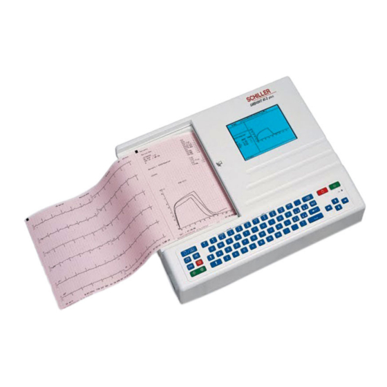
Schiller Cardiovit AT 2 Plus 6 канальный электрокардиограф, осуществляющий одновременную регистрацию всех 12 отведений, и таким образом обеспечивающий немедленную регистрацию ЭКГ.
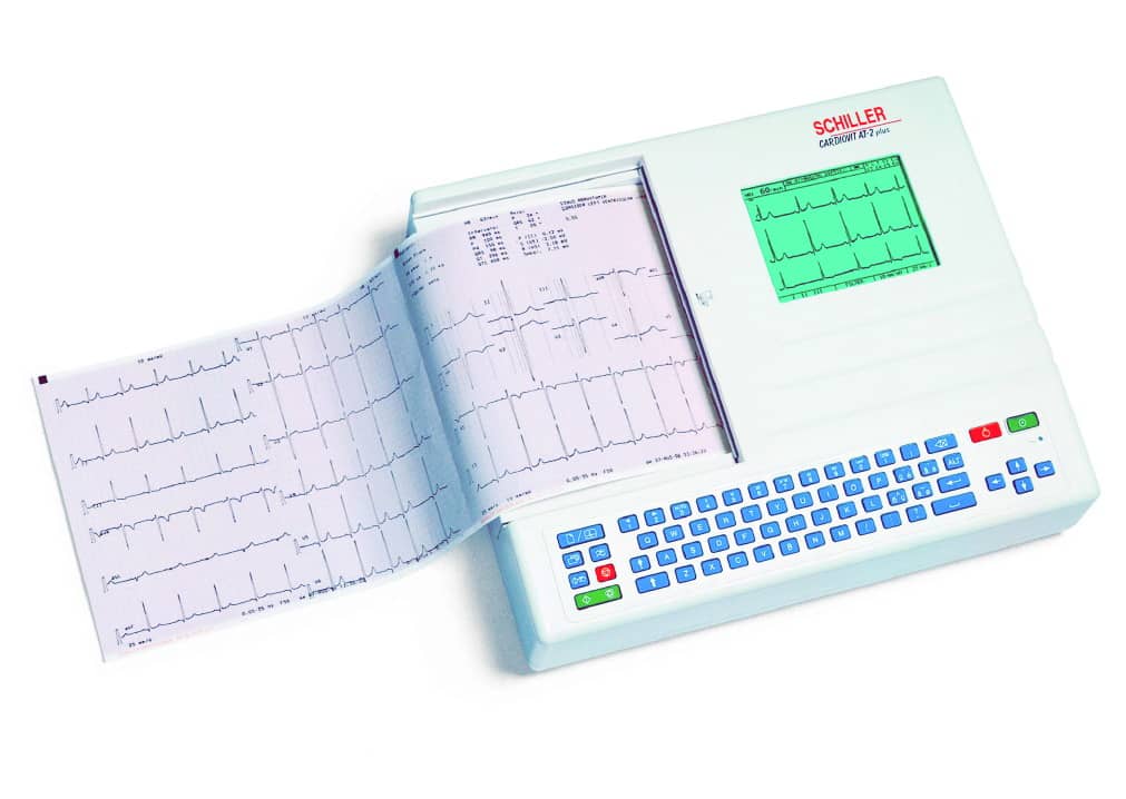
Schiller Cardiovit AT 2 Plus имеет следующие преимущества:
- Небольшой вес и компактные размеры.
- Распечатка формата А4 со встроенного термопринтера.
- Встроенный аккумулятор для независимой работы от сети в течение 4 часов обычного использования или 300 распечаток на один заряд.
- Большой жидкокристаллический экран для просмотра ЭКГ перед печатью.
- Действие совершается простым нажатием клавиш.
- Автоматический и ручной режимы регистрации.
- Возможность выбора форматов печати.
- Память ЭКГ с возможностью копирования ЭКГ.
- Программа интерпретации (включая измерения) для взрослых и детей.
- Буквенно- цифровая клавиатура для ввода данных пациента и замечаний врача.
Производитель Schiller Cardiovit AT 2 Plus
Производитель электрокардиографа Schiller Cardiovit AT 2 Plus – Фирма «SCHILLER AG». Страна производитель Швейцария.
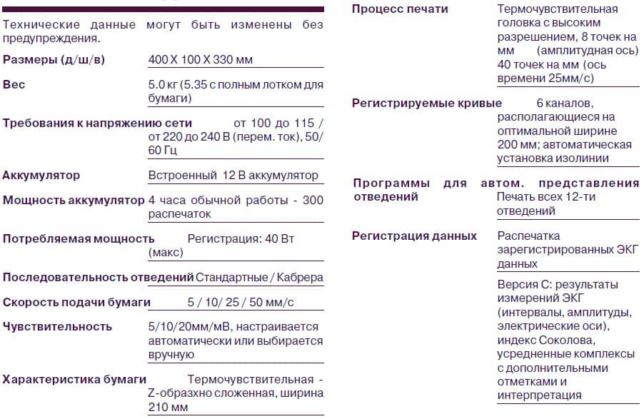
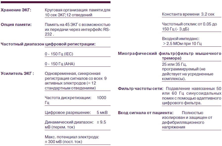
Технические характеристики Schiller Cardiovit AT 2 Plus
Ниже указаны технические характеристики на аппарат ЭКГ Schiller Cardiovit AT 2 Plus.

Режимы работы Schiller Cardiovit AT 2 Plus
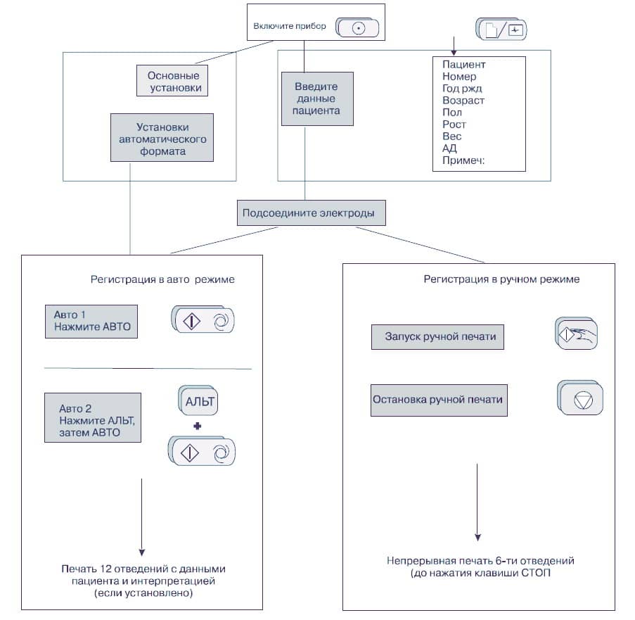
Автоматический режим
Автоматический режим допускает печать десяти секунд ЭКГ, зарегистрированной по всем 12 отведениям, в двух различных форматах.
До регистрации в каждом из форматов можно запрограммировать следующее:
- Формат отведения.
- Скорость подачи бумаги.
- При инсталлированной программе интерпретации возможен выбор таблицы измерений , усредненных комплексов с отметками и интерпретационными сообщениями для печати.
Ручной режим
Ручной режим допускает печать шести отведений, выбираемых и индицируемых на экране, в режиме реального времени.
В течение регистрации возможен следующий выбор:
- Группы отведений.
- Скорости подачи бумаги.
- Чувствительности.
- Миографического фильтра.
Подсоединение кабеля пациента
Набор принадлежностей электрокардиографа включает 10- проводный кабель пациента. Этот кабель подсоединяется к гнезду кабеля пациента на правой боковой панели прибора и закрепляется двумя винтами.
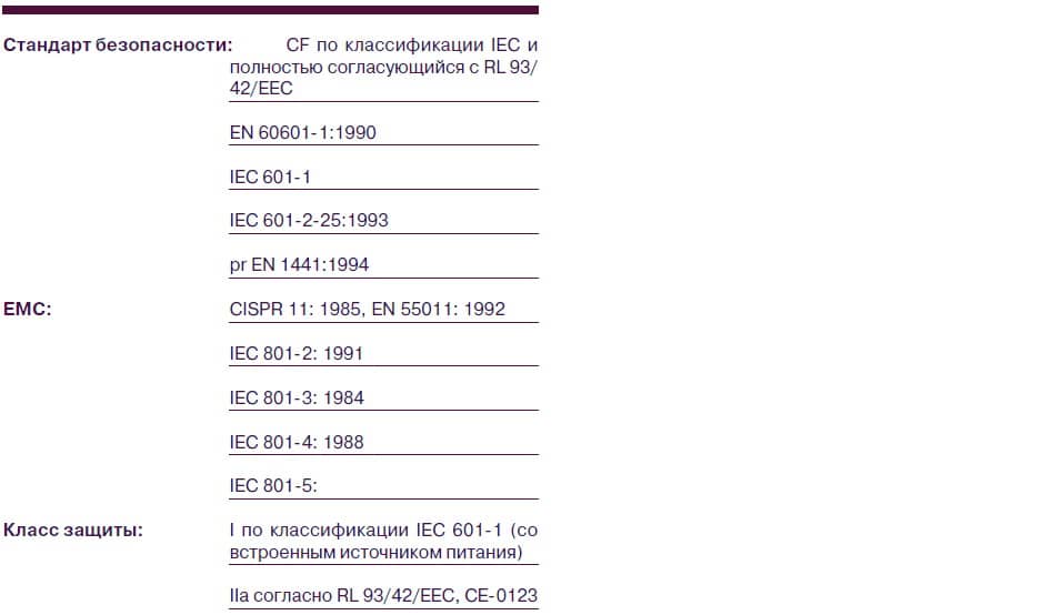
Электрокардиограф относится к классу СF. Это означает, что отведения и наложенные на пациента электроды для ЭКГ полностью изолированы и защищены от дефибрилляционного напряжения. Защита от дефибрилляционного напряжения гарантирована только в случае использования кабеля пациента производства фирмы SCHILLER (катал. номер 2.400070). Для записи электрокардиограммы нужно убедиться в том, что ни пациент, ни токопроводящие части наложенных на него электродов (включая нейтральный электрод), не контактируют с другим человеком или другими токопроводящими предметами, (даже если они заземлены).
Качество ЭКГ зависит от подготовки области наложения электрода и величины сопротивления между кожей и электродом. Для гарантии хорошего качества ЭКГ и минимизации сопротивления кожа/
электрод необходимо помнить о следующем:
- Убедитесь, что в помещении тепло и пациент расслаблен.
- Побрейте область наложения электрода до того, как очистить ее.
- Очистите область наложения электрода спиртовым тампоном.
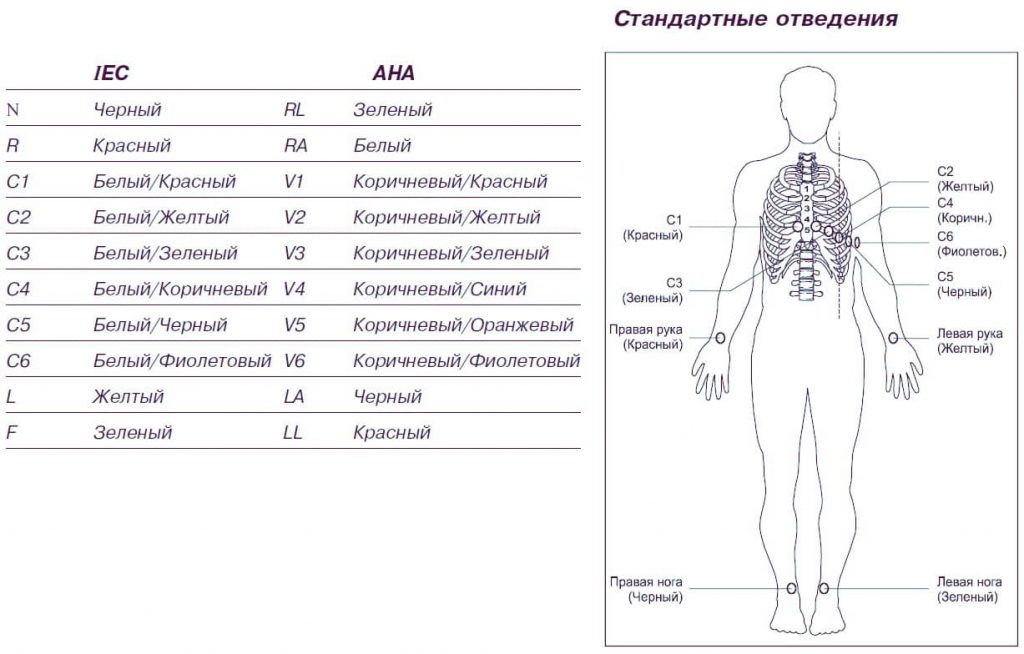
- Первым прикрепите электрод С4 в пятом межреберье по среднеключичной линии.
Расположение электродов:
- C1 в четвертом межреберье по правому краю грудины.
- C2 в четвертом межреберье по левому краю грудины.
- C3 между С4 и С2 на равном расстоянии.
- C6 по левой среднеподмышечной линии на уровне С4
- C5 между С4 и С6 на равном расстоянии.
Подсоединение кабеля ЭКГ
Клавиатура
Ниже представлено описание функций клавиш клавиатуры Schiller Cardiovit AT 2 Plus.
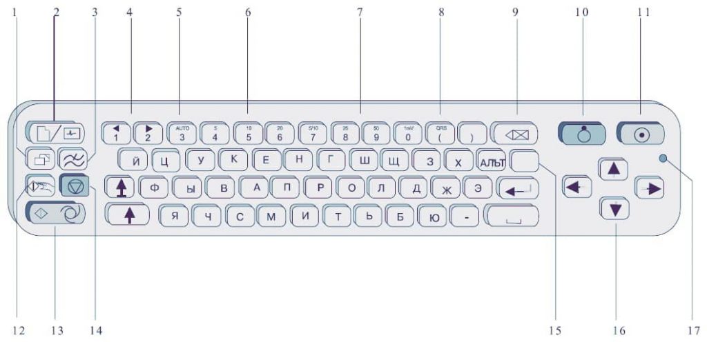
- Печать дополнительной копии если текущая регистрация произведена в автоматическом режиме (из памяти). Для получения дополнительной распечатки в формате 2 , сначала нажмите клавишу АЛЬТ.
- Визуализация / ввод данных пациента. При выведенных на экран данных пациента нажмите клавишу снова для возвращения к экрану ЭКГ.
- Включение / выключение миографического фильтра. Отсекающая частота устанавливается в “Установках”.
- Эти клавиши служат для изменения групп отведений, представленных на экране.
- Установки автоматической чувствительности для печати (только в автоматическом режиме) для подбора оптимальной величины сигнала (5мм/мВ или 10мм/мВ).
- Верхняя часть клавиш имеет обозначения 5, 10 и 20 для выбора чувствительности ЭКГ на экране и на (ручной) печати. Возможные установки чувствительности 5, 10, 20 мм/мВ.
- Верхняя часть клавиш имеет обозначения 5, 10, 25 и 50, которые являются установками скорости ЭКГ на экране и (ручной) печати. Скорость экрана может быть установлена на 25 или 50 мм/с. Скорость распечатки в ручном режиме может быть 5, 10, 25 или 50 мм/с. Установками скорости 5 и 10 мм/с обладает одна клавиша.
- Верхний символ отвечает за включение / выключение бипера QRS.
- Удаление последнего действия / символа.
- Выключение прибора.
- Включение прибора.
- В ручном режиме запуск непрерывной печати ЭКГ – до нажатия клавиши СТОП.
- Регистрации ЭКГ в автоматическом режиме (формат 1). Нажмите АЛЬТ перед клавишей АВТО для получения формата 2.
- Остановка печати / подтверждение (новых) установок.
- Клавиша АЛЬТ инициирует установку и выбирает второй формат для печати и регистрации автоматического режима.
- В режиме ЭКГ используйте клавиши вверх / вниз для настройки контрастности экрана. При вводе данных пациента используйте клавиши направо / налево для передвижения курсора в поле.
- Индикатор сети горит при работе от сети.
Экран Schiller Cardiovit AT 2 Plus
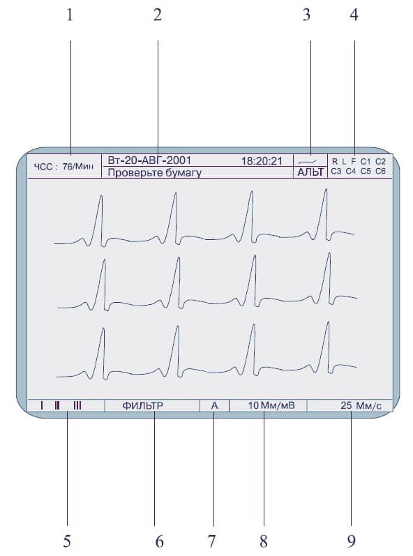
- Текущая ЧСС (усредняются каждые 4 сокращения и обновляется каждые 2 секунды). ЧСС приводится и на распечатке в ручном режиме. Учтите, в автоматическом режиме ЧСС усредняется за каждые 10 секунд регистрации.
- Верхняя строка – текущие день недели, дата и время. Нижняя строка – системные сообщения.
- Верхняя строка источник питания сеть или аккумулятор. Когда мощность аккумулятора снижается, символ мигает Нижняя строка – АЛЬТ в этом поле означает, что клавиша АЛЬТ – нажата.
- Подсоединение электродов если отведение мигает, сопротивление электрода слишком высоко. Электрод должен быть переустановлен.
- Индикатор отведений (текущих отведений, демонстрируемых экраном). Изменить группу отведений можно клавишами (1) и (2).
- Индикатор миографического фильтра: “ФИЛЬТР” фильтр включен, нет индикации фильтр выключен.
- (А) В этом поле свидетельствует о том, что выбрана установка автоматической чувствительности (активна только при авто режиме). Включение / выключение авто чувствительности клавишей (3).
- Чувствительность 5, 10, 20 мм/мВ. Изменение чувствительности с помощью клавиш (4), (5) и (6).
- Скорость 25 или 50 мм/с. Изменение скорости с помощью клавиш (8) и (9).
Установки Schiller Cardiovit AT 2 Plus
Все параметры устанавливаются с помощью кода. Этот код состоит из комбинации клавиш, которая всегда начинается с клавиши АЛЬТ, затем следует последовательность цифровых клавиш, и в заключении ввод подтверждается клавишей СТОП. Как только нажата клавиша ALT, клавиатура работает на функцию программирования.
При нажатии клавиши АЛЬТ символ ‘АЛЬТ’ появляется на экране. Функция АЛЬТ активна только 4 секунды. Если клавиши для программирования не нажаты в течении 4 секунд прибор возвращается в стандартный режим. Для активации режима программирования клавиша АЛЬТ должна быть нажата заново.
Установки запоминаются после нажатия клавиши STOP, и клавиатура освобождается для выполнения других функций. Однажды подтвержденные установки сохраняются даже тогда, когда прибор выключен.
Более подробные установки можно посмотреть в инструкции на аппарат. Скачать руководство пользователя можно в конце статьи.
Установка языка Schiller Cardiovit AT 2 Plus
Язык выбирается следующим образом:
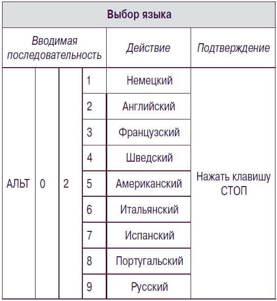
Подтвердите выбор нажатием клавиши СТОП.
Установка даты и времени Schiller Cardiovit AT 2 Plus
Установка даты и времени Schiller Cardiovit AT 2 Plus осуществляется следующим образом:

Техническое обслуживание Schiller Cardiovit AT 2 Plus
Прибор должен проходить технический контроль каждые 12 месяцев. Во время проверки должно быть выполнено и документировано следующее:
- Визуальный осмотр прибора и кабеля пациента.
- Тесты электрической безопасности по IEC 601 1 и IEC 601 2 25.
- Тесты функционального состояния прибора согласно сервисному руководству.
Результаты тестов должны быть документированы.
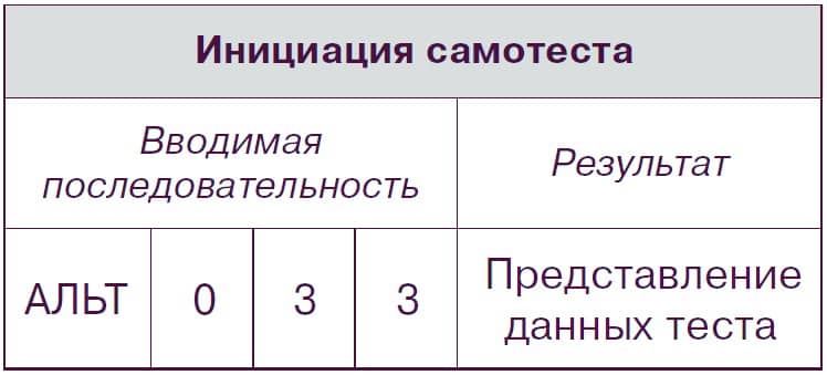
Самотест
Самотестирование Schiller Cardiovit AT 2 Plus инициируется следующим образом:
Очистка кабеля пациента
Кабель пациента не должен подвергаться излишним механическим нагрузкам. При отсоединении отведений, держитесь за штеккер, а не за кабель. Обеспечьте безопасные условия хранения и транспортировки прибора и кабеля.
Кабель можно мыть мыльной водой. Стерилизация, если требуется, должна проводиться только газом и без пара. Для дезинфекции протрите кабель стандартными средствами дезинфекции, применяющимися в Вашем учреждении.
Очистка термопечатающеего устройства
При частом использовании термоголовка может загрязняться, что может привести к ухудшению качества печати. Для предотвращения этого рекомендуется ежемесячно очищать термоголовку принтера.
Снимите крышку отсека бумаги. Термоголовка находится за планкой фиксации крышки отсека для бумаги. Мягкой тканью, слегка смоченной спиртом, осторожно протрите термоголовку.
Замена бумаги
Красная полоска по нижнему краю регистрирующей бумаги свидетельствует о том, что бумага заканчивается. Появление этой полоски указывает на то, что осталось около 8 страниц. Рекомендуется заменить бумагу сразу после появления полоски. В случае окончания бумаги начнет мигать индикаторная лампа, и процесс печати будет прерван.
Для замены бумаги проделайте следующее:
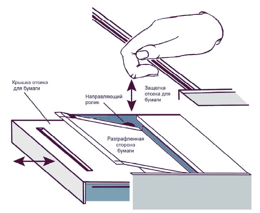
- Захватите пальцами задвижку, крепящую отсек для бумаги, и потяните вверх.
- В подтверждение правильности выполненных действий отсек, покрывающий бумагу, слегка отскочит влево.
- Удалите отсек, затем оставшуюся бумагу.
- Расположите в отделении новую упаковку бумаги. Проверьте, чтобы печатаемая (разлинованная) сторона располагалась «лицом» вверх, бумага должна выходить на переднюю панель прибора, огибая черный ролик.
- Установите крышку отсека для бумаги на место для щелчка.
- Для перемещения бумаги в начальную позицию нажмите клавишу СТОП.
Ошибки и неисправности Schiller Cardiovit AT 2 Plus
Ниже указаны неисправности аппарата ЭКГ Schiller Cardiovit AT 2 Plus и способы их устранения.
Прибор не включается, экран не функционирует.
Включен ли индикатор сети? Нет? Проверьте источник питания. Да? Проверьте контрастность экрана с помощью курсоров вверх / вниз. Если сеть в порядке, а экран так и не функционирует: Нажмите клавишу ВЫКЛ. Подождите несколько секунд и включите прибор снова. Если экран так и не реагирует, свяжитесь с представителем Schiller медицинское оборудование.
Наложение комплексов QRS.
Убедитесь, что автоматическое уменьшение чувствительности не отключено. Нажмите клавишу 1 мВ для переустановки изолинии. Проверьте контакт электродов.
«Шумные» кривые.
Проверьте контакт электродов. Наложите электроды заново. Убедитесь, что пациент расслаблен и ему тепло. Проверьте все установки фильтров. Включите миографический фильтр – проверьте частоту. Убедитесь, что установка сетевого фильтра соответствует напряжению сети.
После автоматического запуска нет распечатки.
Убедитесь в наличии бумаги. Проверьте установки – убедитесь, что, в авто формате ЭКГ выбрана, по крайней мере, одна позиция для печати. Запустите печать в ручном режиме, если принтер все еще бездействует обратитесь к представителю SCHILLER.
Распечатка постепенно исчезает или «нечистая».
Убедитесь, что вставлена новая бумага от SCHILLER. Помните, что термочувствительная бумага для AT 4 чувствительна к теплу и свету. Если бумага хранится не в оригинальной упаковке, при высокой температуре или она просто старая, то качество печати может ухудшиться. Убедитесь, что бумага вставлена правильно с отметкой в верху. Проверьте, защелкнут ли отсек для бумаги. При истечении некоторого времени чернила с печатной стороны бумаги могут сохраняться на головке принтера. Очистите головку принтера.
Нет распечатки интерпретационных сообщений или измерений.
Проверьте, доступны ли для печати опции интерпретация и измерения. Проверьте, чтобы выбранный формат включал установки измерения и интерпретации.
Клавиши не функционируют, экран завис.
Выключите прибор, подождите несколько секунд и включите снова.
Принадлежности и расходные материалы

Аккумулятор Schiller Cardiovit AT 2 Plus
Аккумулятор 12V-2,2Ah для ЭКГ аппарата Schiller Cardiovit AT 2 Plus.

Технические характеристики аккумулятора
- Напряжение (В): 12;
- Емкость (А.ч): 2,2;
- Габариты (ДхШхВ): 178x34x60 мм;
- Вес: 0.93 кг;
- Срок службы: при t = 20 C — 5 лет;
- Тип клем: Faston 187;
- Применение: в циклическом или буферном режиме.
Скачать инструкцию на Schiller Cardiovit AT 2 Plus
Скачать инструкцию и другую документацию на электрокардиограф Schiller Cardiovit AT 2 Plus можно здесь.
Руководство пользователя ( user manual ) на русском языке Schiller Cardiovit AT 2 Plus скачать.
Регистрационное удостоверение Schiller Cardiovit AT 2 Plus скачать.
Сертификат соответствия Schiller Cardiovit AT 2 Plus скачать.
Свидетельство об утверждении типа средств измерений Schiller Cardiovit AT 2 Plus скачать.
Так же смотрите Schiller AT-101 12-канальный электрокардиограф, сфигмоманометр Schiller BR-102 plus.
![]()
SCHILLER AT-2plus 6-Channel ECG Unit
SERVICE HANDBOOK Issue d May 2002
AT-2plus
Memory
6-Channel ECG unit
Service Handbook
SCHILLER AG
Altgasse 68
CH-6341 Baar, Switzerland
Phone: + 41 41 766 42 42
Fax: + 41 41 761 08 80
Home page: http://www.schiller.ch/
|
May 2002 |
Article Number: 2.540014 |
i

SCHILLER AT-2plus 6-Channel ECG Unit
SERVICE HANDBOOK Issue d May 2002
AT-2plus Memory Service Handbook
Article Number 2. 540014d
|
Issue 1 : |
June 1998 |
||
|
Issue 2 : |
December 1999 |
Schematics: 2480BC, 2482CA, 2483BF, 2485BA |
|
|
Issue c : |
September 2001 |
Schematics: |
2480BC, 2482CA, 2483DA, 2485BA |
|
Issue d : |
May 2002 |
Schematics: |
2480BC, 2482CA, 2483DA, 2485BA |
Associated Documents
|
Guide to the SCHILLER Interpretation |
||
|
and Measurement Program E/ D/ F |
Article No. |
2. 510179 |
|
SCHILLER AT-2plus User Guide — English / German / French |
Article No. |
2. 510220 |
|
SCHILLER AT-2plus User Guide — Italian / Spanish / Portuguese |
Article No. |
2. 510221 |
|
SCHILLER AT-2plus User Guide — Swedish |
Article No. |
2.510321 |
|
SCHILLER AT-2plus Short Form User Guide — Swedish |
Article No. |
2.510245 |
© SCHILLERAG 2001
Windows™ is a trademark of Microsoft Corporation.
ii

SCHILLER AT-2plus 6-Channel ECG Unit
SERVICE HANDBOOK Issue d May 2002
Where to Obtain Service
|
WELCH ALLYN SCHILLER Inc., 7420 Carroll Road, San Diego, CA , US-92121-2334 |
|||
|
USA |
|||
|
USA / Canada |
|||
|
Tel.: +1 858 635 6023 |
Fax : +1 858 635 6611 |
||
|
Home Page : www.welchallyn.com |
|||
|
SCHILLER Asia Pacific, 10 Jalan SS 3/33, Taman Universiti, 47300 Petaling Jaya, Selangor, |
|||
|
Asia Pacific |
Malaysia |
||
|
Tel.: + 603 7877 5336 |
Fax : + 603 7877 5744 |
||
|
Austria |
SCHILLER HmbH, Kampmüllerweg 24, A-4044 Linz, Austria |
||
|
Tel.: + 43 732 709 90 |
Fax : + 43 732 757 000 |
||
|
SCHILLER Medical S.A, BP 50, 19, Avenue de la Gare, F-67162 Wissembourg / Cedex, |
|||
|
France |
France |
||
|
Tel.: +33 3 88 63 36 00 |
Fax : +33 3 88 94 12 82 |
||
|
Germany (EU |
SCHILLER Medizintechnik GmbH, Rudolf-Diesel Strasse 14, D-85521 Ottobrunn, Germany |
||
|
authorized |
|||
|
Tel.: + 4989 629 981 0 |
Fax : + 4989 609 509 0 |
||
|
representative) |
|||
|
SCHILLER Healthcare India Pvt. Ltd.,D.C.Silk Mills Compound, ‘A’ Wing, 1st floor, 5, |
|||
|
India |
Chunawala Estate, Kondivitta Lane, Andheri — Kurla Road, Andheri (E, Mumbai — 400 059, |
||
|
India |
|||
|
Tel.: + 9122 826 3520 |
Fax : + 9122 826 3525 |
||
|
Italy |
ESAOTE Spa (SCHILLER), Via di Caciolle 15, I-50127 Firenze, Italy |
||
|
Tel.: + 39055 4229 201 |
Fax : + 39055 4229 208 |
||
|
Switzerland |
SCHILLER Reomed AG, Riedstrasse 14, CH-8953 Dietikon, Switzerland |
||
|
Tel.: +411 744 3000 |
Fax : + 411 740 3710 |
||
|
SCHILLER AG, Altgasse 68, CH-6341 Baar, Switzerland |
|||
|
All other |
|||
|
Tel.: + 4141 766 4242 |
Fax : + 4141 761 0880 |
||
|
countries |
|||
|
Home Page : www.schiller.ch |
|||
iii

SCHILLER AT-2plus 6-Channel ECG Unit
SERVICE HANDBOOK Issue d May 2002
Warranty
Terms of Warranty
The SCHILLER AT-2plus Memory is warranted against defects in material and manufacture for the duration of one year (as from date of purchase). Excluded from this guarantee is damage caused by an accident or as a result of improper handling. The warranty entitles free replacement of the defective part. Any liability for subsequent damage is excluded. The warranty is void if unauthorized or unqualified persons attempt to make repairs.
In case of a defect, contact your dealer or the manufacturer.
The manufacturer can only be held responsible for the safety, reliability, and performance of the apparatus if:
*assembly operations, extensions, readjustments, modifications, or repairs are carried out by persons authorized by him, and
*the AT-2plus Memory and approved attached equipment are used in accordance with the manufacturers instructions.
THERE ARE NO EXPRESS OR IMPLIED WARRANTIES WHICH EXTEND BEYOND THE WARRANTIES HEREINABOVE SET FORTH. SCHILLER MAKES NO WARRANTY OF MERCHANTABILITY OR FITNESS FOR A PARTICULAR PURPOSE WITH RESPECT TO THE PRODUCT OR PARTS THEREOF.
iv

SCHILLER AT-2plus 6-Channel ECG Unit
SERVICE HANDBOOK Issue d May 2002
Safety Notices
WARNINGS & CAUTIONS
TO PREVENT ELECTRIC SHOCK DO NOT DISASSEMBLE THE UNIT. NO SERVICEABLE PARTS INSIDE. REFER SERVICING TO QUALIFIED PERSONNEL ONLY.
DO NOT USE THIS UNIT IN AREAS WHERE THERE IS ANY DANGER OF EXPLOSION OR THE PRESENCE OF FLAMMABLE GASES SUCH AS ANAESTHETIC AGENTS.
IF THE DISPLAY IS DAMAGED, A LEAKAGE OF FLUID MAY OCCUR. DO NOT INHALE THE VAPOUR FROM THIS FLUID AND AVOID CONTACT WITH MOUTH AND SKIN. IF CONTACT IS MADE, CLEAN CONTAMINATED AREA IMMEDIATELY WITH FRESH WATER.
THIS PRODUCT IS NOT DESIGNED FOR STERILE USE.
SWITCH THE UNIT OFF BEFORE CLEANING AND DISCONNECT FROM THE MAINS.
DO NOT, UNDER ANY CIRCUMSTANCES, IMMERSE THE UNIT OR CABLE ASSEMBLIES IN LIQUID.
DO NOT OPERATE THE UNIT IF THE EARTH CONNECTION IS SUSPECT OR IF THE MAINS LEAD IS DAMAGED OR SUSPECTED OF BEING DAMAGED.
DO NOT USE HIGH TEMPERATURE STERILISATION PROCESSES (SUCH AS AUTOCLAVING). DO NOT USE E-BEAM OR GAMMA RADIATION STERILISATION.
DO NOT USE SOLVENT CLEANERS
USE ONLY ACCESSORIES AND OTHER PARTS RECOMMENDED OR SUPPLIED BY SCHILLER AG. USE OF OTHER THAN RECOMMENDED OR SUPPLIED PARTS MAY RESULT IN INJURY INACCURATE INFORMATION AND/ OR DAMAGE TO THE UNIT.
THIS UNIT COMPLIES WITH EMC REGULATIONS FOR MEDICAL PRODUCTS WHICH AFFORDS PROTECTION AGAINST EMISSIONS AND ELECTRICAL INTERFERENCE. HOWEVER SPECIAL CARE MUST BE EXERCISED WHEN THIS UNIT IS USED WITH HIGH FREQUENCY EQUIPMENT.
IT MUST BE ENSURED THAT NEITHER THE PATIENT NOR THE ELECTRODES (INCLUDING THE NEUTRAL ELECTRODE) COME INTO CONTACT WITH OTHER PERSONS OR CONDUCTING OBJECTS (EVEN IF THESE ARE EARTHED).
THERE IS NO DANGER WHEN USING THE ECG UNIT FOR A PACEMAKER PATIENT OR WITH SIMULTANEOUS USE OF OTHER ELECTRICAL STIMULATION EQUIPMENT. HOWEVER, THE STIMULATION UNITS SHOULD ONLY BE USED AT A SUFFICIENT DISTANCE FROM THE ELECTRODES. IN CASE OF DOUBT, THE PATIENT SHOULD BE DISCONNECTED FROM THE RECORDER.
v

SCHILLER AT-2plus 6-Channel ECG Unit
SERVICE HANDBOOK Issue d May 2002
Safety Notices
WARNINGS & CAUTIONS
THIS UNIT IS CF  CLASSIFIED ACCORDING TO IEC 601-1. THIS MEANS THAT THE PATIENT CONNECTION IS FULLY ISOLATED AND DEFIBRILLATION PROTECTED. SCHILLER CAN ONLY GUARANTEE PROTECTION AGAINST DEFIBRILLATION VOLTAGE, HOWEVER, WHEN THE ORIGINAL SCHILLER PATIENT CABLE IS USED.
WHEN NON-MEDICAL DEVICES ARE CONNECTED TO THE RS-232 INTERFACE ENSURE THAT BOTH UNITS ARE SECURELY CONNECTED TO THE SAME EARTH POTENTIAL.
WHEN OPERATING THE UNIT ON BATTERY AND SIMULTANEOUSLY USING NONMEDICAL DEVICES, THE RS-232 INTERFACE MUST BE FULLY ISOLATED.
AN EXTERNAL DEVICE MUST ONLY BE CONNECTED USING THE ORIGINAL SCHILLER INTERFACE CABLE ASSEMBLY.
BEFORE USING THE UNIT, ENSURE THAT AN INTRODUCTION REGARDING THE UNIT FUNCTIONS AND THE SAFETY PRECAUTIONS HAS BEEN PROVIDED BY A SCHILLER REPRESENTATIVE.
THE GUIDELINES FOR PATIENT ELECTRODE PLACEMENT ARE PROVIDED AS ON OVERVIEW ONLY. THEY ARE NOT A SUBSTITUTE FOR MEDICAL EXPERTISE.
THIS UNIT IS PROVIDED FOR THE EXCLUSIVE USE OF QUALIFIED PHYSICIANS OR PERSONNEL UNDER THEIR DIRECT SUPERVISION. THE NUMERICAL AND GRAPHICAL RESULTS AND ANY INTERPRETATION DERIVED FROM A RECORDING MUST BE EXAMINED WITH RESPECT TO THE PATIENTS OVERALL CLINICAL CONDITION. THE RECORDING PREPARATION QUALITY AND THE GENERAL RECORDED DATA QUALITY, WHICH COULD EFFECT THE REPORT DATA ACCURACY, MUST ALSO BE TAKEN INTO ACCOUNT.
IT IS THE PHYSICIANS RESPONSIBILITY TO MAKE THE DIAGNOSIS OR TO OBTAIN EXPERT OPINION ON THE RESULTS, AND TO INSTITUTE CORRECT TREATMENT IF INDICATED.
vi

SCHILLER AT-2plus 6-Channel ECG Unit
SERVICE HANDBOOK Issue d May 2002
What’s in this book
The service philosophy for the AT-2plus Memory is fault finding to module level. The purpose of this book is to provide all the information necessary to enable the service engineer to efficiently locate and replace a faulty module. This book assumes no detailed knowledge of the AT-2plus Memory but does require that the service engineer is familiar with standard workshop practices. The book is divided into the following chapters:
Chapter 1 — Operating Elements
The purpose of this chapter is to provide an easy reference for all the main operator functions and to give a basic introduction to the AT-2plus Memory. This chapter gives details of the operator controls with the operation and function of each key briefly explained. The information in this chapter provides a background to the operating functions only. Complete operating information is provided in the SCHILLER AT-2plus User Guide.
Chapter 2 — Functional Overview
This chapter provides a functional overview of the AT-2plus Memory. The description is supported by functional block diagrams.
Chapter 3 — Fault Diagnosis
This chapter provides a guide to locate a fault to module level. The diagnostics are presented in a logical sequence of fault finding algorithms and procedures. Illustrations are provided to support the text where needed.
Chapter 4 — Module Removal and Replacement
This chapter gives an overview of the physical construction of the AT-2plus Memory with the main physical attributes of the unit briefly described. The physical description is supported by illustrations showing the internal location of all modules. Removal and replacement instructions for all removable modules are also provided in this chapter. Each procedure is autonomous with details of tools, jumper settings, adjustments and settings or special requirements that are required before and after replacement. Functional checks that must be carried out after replacing a module are also provided.
Chapter 5 — Adjustments
This chapter provides all adjustments and settings. Also detailed in this chapter are basic functional test procedures that can be performed to check the functioning of the unit.
Chapter 6 — Spare Parts
This chapter provides the part numbers and reordering information for all replaceable modules. Also included in this chapter are details of any special test equipment or special tools required for adjustment or fault finding procedures.
vii

SCHILLER AT-2plus 6-Channel ECG Unit
SERVICE HANDBOOK Issue d May 2002
What’s in this book
Chapter 7 — Technical Data
The full technical specification of the AT-2plus Memory is given in this chapter.
Chapter 8 — Glossary
This chapter explains all the acronyms and signal titles used in this book and in the AT-2plus Memory circuit diagrams.
Circuit Diagrams & Board layouts
The circuit diagrams and component layouts are provided for all boards. These details are provided for information only.
viii

|
SCHILLER AT-2plus 6-Channel ECG Unit |
Chapter 1 |
|
SERVICE HANDBOOK Issue d May 2002 |
Operating Elements |
Chapter 1
Operating Elements
|
Contents |
|
|
Introduction |
1.2 |
|
List of Symbols |
1.2 |
|
Location & Power |
1.3 |
|
Switching On and Off |
1.3 |
|
The Keyboard |
1.4 |
|
LCD Screen |
1.6 |
|
AT-2plus Short Form Operating Instructions |
1.7 |
|
Modes of Operation |
1.8 |
|
Automatic Mode |
1.9 |
|
Manual Mode |
1.10 |
|
Settings |
1.12 |
|
Automatic Mode (ECG) Settings |
1.20 |
|
Memory and Data Transmission Option |
1.24 |
|
Erasing Memory Files |
1.25 |
|
Transmitting Stored Files |
1.25 |
|
Transmission Settings |
1.25 |
|
Modem Transmission |
1.26 |
|
Line Transmission |
1.27 |
|
Software Updating via RS-232 |
1.28 |
|
Care & Maintenance |
1.29 |
|
Replacing the Recording Paper |
1.31 |
|
Thermal Paper Handling |
1.32 |
Page 1.1

|
Chapter 1 |
SCHILLER AT-2plus 6-Channel ECG Unit |
|
Operating Elements |
SERVICE HANDBOOK Issue d May 2002 |
Introduction
The CARDIOVIT AT-2plus is a 6-channel ECG recorder with all (12) ECG signals simultaneously processed to provide instant ECG recordings. Two automatic recording modes can be individually preset to enable one button ECG recording of preferred print formats.
The AT-2plus includes the following features:
•Low weight and compact dimensions
•Large A4 size printout from integrated quality thermal printer
•Built-in rechargeable battery for mains-independent use — 4hrs normal use or 300 printouts on one battery charge
•Large, clear LCD for ECG preview prior to printing
•Simple one key operation for main functions
•Automatic or manual recording modes
•Selectable printing formats
•ECG memory for easy copying
•Interpretation program option (including measurements) for children and adults
•Alphanumeric keyboard for patient data entry and clinical comments
List of Symbols
Page 1.2
![]()
|
SCHILLER AT-2plus 6-Channel ECG Unit |
Chapter 1 |
|
SERVICE HANDBOOK Issue d May 2002 |
Operating Elements |
Location & Power
Location
Do not keep or operate the apparatus in a wet, moist, or dusty environment. Also, avoid exposure to direct sunlight or heat from other sources. Do not allow the unit to come into contact with acidic vapours or liquids, as such contact may cause irreparable damage. The unit should not be placed near X-ray or diathermy units, large transformers or motors. The unit must be placed on a flat surface and must not be operated in areas where there is any danger of explosion.
Power Supply
The mains connection is on the rear of the unit. The mains indicator lamp on the keyboard is always lit when the unit is connected to the mains supply. The unit can either be operated from the mains supply or from the built-in rechargeable battery. The power source isa indicted on the top line of the LCD.
Power Indication
|
HR: 76/min |
Wed 20-AUG-96 18:20:21 |
R L F C1 C2 |
||||
|
C3 C4 C5 C6 |
||||||
When mains is connected a mains symbol is displayed (as shown above). When the unit is running on battery power a battery symbol is displayed: 
When battery capacity is limited, the battery symbol flashes on and off.
To recharge the battery, connect the apparatus to the mains supply by means of the supplied power cable. A totally discharged battery needs less than 15 hours to be fully recharged (60% in less than 3 hours, 90% in less than 7 hours). A fully charged battery gives approximately 4 hours of normal use. The unit can remain connected to the mains supply without any danger of damage to either the battery or the unit.
Switching On and Off
The CARDIOVIT AT-2plus is switched on with the green ON key
and off by means of the red OFF key
The unit is automatically switched off after 5 minutes (30 seconds if battery capacity is limited) if no key is pressed and the patient cable is not connected.
Potential Equalisation 
If the AT-2plus is used in conjunction with other patient connected equipment, we recommend that the potential equalisation stud on the rear of the unit is connected to the hospital/ building common ground with the yellow/green ground cable (Part-no. 2.310005). When working from an emergency vehicle, the vehicle common ground can be used.
Page 1.3

|
Chapter 1 |
SCHILLER AT-2plus 6-Channel ECG Unit |
|
Operating Elements |
SERVICE HANDBOOK Issue d May 2002 |
The Keyboard
Page 1.4

|
SCHILLER AT-2plus 6-Channel ECG Unit |
Chapter 1 |
|
SERVICE HANDBOOK Issue d May 2002 |
Operating Elements |
The Keyboard (cont.)
1Print extra copy — of Auto mode recording currently in memory. Press the ALT key first followed by this key to obtain a copy in Auto format 2.
2Display/enter patient data. When the patient data is displayed, pressing this key again returns to the ECG. Use the up/down arrows to go to the next data entry field.
In the `Born` (date of birth field), only the patients year of birth need be entered if desired. When two digits are entered (patients year of birth), the AT-2plus calculates the age of the patient according to the year entered. When the full DOB is entered, the age is calculated precisely.
3Myogram filter ON / OFF. The cutoff frequency can be defined and is detailed in `Settings`.
4.The top figures on the number keys designated > and < changes the lead group displayed on the screen.
5.Auto sensitivity key — automatically sets the ECG printout sensitivity ( in AUTO mode only) to the best setting for the signal strength (5mm/mV or 10mm/mV)
6.The top figures on the number keys designated 5, 10, and 20 set the sensitivity of the ECG both on the screen and on the (manual) printout. The sensitivity is 5, 10 or 20 mm / mV.
7.The top figures on the number keys designated 5/10, 25, and 50 set the speed of the ECG both on the screen and on the (manual) printout. The speed on the screen can only be set to 25 or 50 mm / s. The speed of the manual printout can be 5, 10, 25 or 50 mm/s. The 5 and 10 mm/s settings are both on the same key which toggles the two speeds.
8.The top character `QRS` toggles the QRS beeper ON/ OFF
9.Delete last typed character.
10.Switch the unit OFF.
11.Switch the unit ON.
12.Manual mode recording — start continuous printout of ECG — until STOP key pressed
13.Auto Mode recording (in Auto mode 1). Press ALT followed by the AUTO key for auto mode 2.
14.STOP printout / confirm (new) setting
15.ALT key — key for initiation of setups and selection of second format for printout and auto mode recording
16.In ECG mode use the UP/DOWN arrows to adjust screen contrast. When entering patient data use the LEFT/RIGHT arrow keys to move cursor in data field. Use the UP/DOWN arrow keys to go up/down to the next data entry
17.Mains Indicator — lit when mains connected.
Second letters on the keyboard — è, é, ç, ø are reached by holding the ALT key pressed before the letter key. Accents on a letter e.g. ô, ñ etc. are reached by pressing <SHIFT> and then the letter. In addition the following special characters are available (AT-2plus Memory only !):
|
Key combination: SHIFT + |
1 |
2 |
3 |
4 |
5 |
6 |
7 |
8 |
9 |
0 |
|
Character |
! |
@ |
# |
$ |
% |
& |
/ |
* |
« |
= |
Page 1.5

|
Chapter 1 |
SCHILLER AT-2plus 6-Channel ECG Unit |
|
Operating Elements |
SERVICE HANDBOOK Issue d May 2002 |
LCD Screen
1.Current Heart Rate (averaged over 4 beats and refreshed every 2 seconds). The HR is also given on a manual printout. Note that with an auto mode printout the HR is averaged over the full 10 seconds of the recording.
2.Top line — Current Day, Date and Time Bottom Line — System messages
3.Top Line — Current power source — mains or battery. When battery capacity is limited the battery symbol flashes.
Bottom line — `ALT` in this box indicates that the ALT key has been pressed.
4.Electrode connections — when a lead flashes it indicates that the electrode resistance is too high. The electrode must be reapplied
5.Lead indication (leads currently displayed on the screen). Change the lead group with the keys `1` and `2`.
6.Myogram Filter indication — `Filter` = filter ON; no indication = filter OFF. Switch the filter on or off with the Filter key.
7.An `A` in this box indicates that automatic sensitivity is selected (auto mode printout only). Switch automatic sensitivity on or off with key `3`.
8.Sensitivity — 5, 10 or 20 mm/mV. Change the sensitivity with the keys `4`, `5`, and `6`.
Page 1.6

|
SCHILLER AT-2plus 6-Channel ECG Unit |
Chapter 1 |
|
SERVICE HANDBOOK Issue d May 2002 |
Operating Elements |
AT-2plus Short Form Operating Instructions
Automatic ECG Recording
∙Prepare skin, hook up patient.
∙Switch unit on, press ON  .
.
∙Press and enter patient data.
∙Press again and wait for at least 10 seconds until a clear and stable trace is displayed.
∙Press AUTO to record and print.
∙Press COPY for additional copies.
Manual ECG Recording (Rhythm Strip)
·Prepare skin, hook up patient.
∙Switch unit on, press ON  .
.
∙Press MAN START  .
.
|
∙ Change lead group with |
1 |
and |
2 |
. |
∙ Press STOP to stop the printout.
Electrode hook-up check
|
· |
Press |
ALT |
1mV |
AUTO |
AUTO |
for electrode check. |
|
|
0 |
3 |
3 |
|||||
Best results are obtained when the electrode voltage readings (right column) are between ±50mV.
Filter On/Off
∙Press to switch the (Myogram) filter On / Off.
System Configuration
|
∙ |
Press |
ALT |
1mV |
to print system settings. |
|||
|
0 |
1 |
1 |
|||||
Page 1.7

|
Chapter 1 |
SCHILLER AT-2plus 6-Channel ECG Unit |
|
Operating Elements |
SERVICE HANDBOOK Issue d May 2002 |
Modes of Operation
Automatic Mode
Automatic Mode provides a printout giving 10 seconds of ECG recording of all 12 leads with a choice of 2 different formats.
Lead format and chart speed can be programmed freely for each of the 2 formats before recording.
With the optional interpretation program installed it is also possible to select the measurement table, average cycles with optional markings and interpretation statements for the printout.
For further information see paragraph `Settings for Automatic Mode`.
Manual Mode
Manual Mode provides a real time printout of 6 leads that are selected and indicated on the screen.
The following can be freely selected before or during recording:
|
• |
Lead Group |
• |
Chart Speed |
|
• |
Sensitivity |
• |
Myogram Filter |
For further information see paragraph `ECG Recording in Manual Mode` following.
Page 1.8

|
SCHILLER AT-2plus 6-Channel ECG Unit |
Chapter 1 |
|
SERVICE HANDBOOK Issue d May 2002 |
Operating Elements |
Automatic Mode
In automatic mode, a full 12-lead ECG is printed in one of two predefined formats with a sensitivity of 10 mm/mV. These two formats are selected by the user to suit his specific needs and requirements.
AUTO
When the AUTO SENSITIVITY key 3 is pressed before recording in automatic mode, the unit detects very large waveform amplitudes and sets the sensitivity for the extremity and/or precordial leads to 5 mm/mV to reduce the overlapping of traces. An `A` on the bottom line of the LCD indicates that Auto sensitivity is set.
To start the automatic ECG recording in Format 1, press the AUTO key:
To start the automatic recording in the second format, press the ALT key followed by the AUTO key:
ALT +
The printout gives the following:
•ECG recording of all leads in either Standard or Cabrera format according to selection
•Sensitivity
•Heart Rate
•Speed
•Filter Settings
•Time and Date
•Interpretation statements
•Average Cycles
•Intervals
•Axis
•Sokolow Index (ECG index for hypertrophy)
•Detailed Measurement Table
To obtain an extra printout of the ECG recording in Format 1, simply press the COPY key:
COPY
To obtain an extra printout of the second format, press the ALT key followed by the COPY key:
ALT — COPY
The Auto mode settings for the two formats are detailed in the paragraph entitled `Settings for Automatic Mode` later in this book
Page 1.9

|
Chapter 1 |
SCHILLER AT-2plus 6-Channel ECG Unit |
|
Operating Elements |
SERVICE HANDBOOK Issue d May 2002 |
Manual Mode
Manual mode provides a direct printout of the real-time ECG with full control of parameter selection.
To start the manual recording of a real-time ECG, press the MANUAL Printout key
To stop the manual recording (printout) press the STOP key
The printout provides you with the following:
•Six (selected) leads with lead identification.
•On the lower edge, the chart speed, user identification and filter settings (if on).
•At the top, the heart rate as current average of 4 beats, trace sensitivity, and the time and date
The following can be freely chosen during or before the recording:
|
Lead Group |
by means of the LEAD FORWARD and LEAD BACKWARD |
||||
|
key |
|||||
|
1 |
2 |
||||
|
The following lead groups are selectable: |
|||||
|
• |
I, II, III |
aVR, aVL, aVF |
|||
|
(Cabrera: aVL, I, -aVR / II, aVF, III) |
|||||
|
• |
V1, V2, V3 |
/ |
V4, V5, V6 |
||
|
• |
II, aVF, III |
/ |
V2, V4, V5 |
||
|
• |
V4, V5, V6 |
/ |
V7, V8, V9 |
||
|
Note: |
The LCD only displays three leads at one time. When the lead forward or lead backward |
||||
|
key is pressed, the following /preceding three lead group is displayed |
Leads
For software versions higher than 4.10 it is also possible to chose further leads. The desired leads are activated as shown in the table.
Select leads
|
Entry Key Sequence |
Lead group |
Confirm |
|||||
|
0 |
Rhythm |
ON |
|||||
|
II, avF, III, V2, V4, V5 |
|||||||
|
1 |
Rhythm |
OFF |
|||||
|
II, avF, III, V2, V4, V5 |
|||||||
|
2 |
Left posterior |
ON |
|||||
|
V4, V5, V6, V7, V8, V9 |
|||||||
|
3 |
Left posterior |
OFF |
|||||
|
V4, V5, V6, V7, V8, V9 |
|||||||
|
4 |
Right precordial up to V5r |
ON |
|||||
|
ALT |
7 |
9 |
V1, V2, V3, V3r, V4r, V5r |
Press STOP |
|||
|
5 |
Right precordial up to V5r |
OFF |
key |
||||
|
V1, V2, V3, V3r, V4r, V5r |
|||||||
|
6 |
Right precordial up to V6r |
ON |
|||||
|
V1, V2, V3r, V4r, V5r, V6r |
|||||||
|
7 |
Right precordial up to V6r |
OFF |
|||||
|
V1, V2, V3r, V4r, V5r, V6r |
|||||||
|
8 |
NEHB |
ON |
|||||
|
D, A, J |
|||||||
|
9 |
NEHB |
OFF |
|||||
|
D, A, J |
|||||||
Page 1.10

|
SCHILLER AT-2plus 6-Channel ECG Unit |
Chapter 1 |
||
|
SERVICE HANDBOOK Issue d May 2002 |
Operating Elements |
||
|
Manual Mode (cont.) |
|||
|
Chart Speed |
Select speed 5, 10, 25 or 50mm/s by means of the SPEED keys: |
||
|
5/10 |
25 |
50 |
|
|
7 |
8 |
9 |
|
|
Notes: |
Key 7 is a toggle key -press once and 5 is selected, press a second |
||
|
time and 10mm/s is selected. |
|||
|
When the 25 or 50mm/s key is pressed, the same speed is set on |
|||
|
both the screen and the (manual) printout. When 5 or 10 mm/s is |
|||
|
selected, this affects the manual printout speed only. |
|||
|
Sensitivity |
Select 5, 10 or 20 mm/mV by means of the SENSITIVITY keys: |
||
|
5 |
10 |
20 |
|
|
4 |
5 |
6 |
|
|
Myogram Filter |
Switch the filter ON or OFF with the FILTER key: |
|
`FILTER` is displayed on the bottom line of the LCD when the |
|||
|
filter is switched on. |
|||
|
Recentering |
To re-centre the ECG traces, press the 1mV key |
1mV |
|
|
0 |
|||
WARNING
AFTER HEAVY ARTEFACTS OR LEAD OFF, THE INDICATION OF THE HEART RATE MAY NOT BE RELIABLE.
Page 1.11

|
Chapter 1 |
SCHILLER AT-2plus 6-Channel ECG Unit |
|
Operating Elements |
SERVICE HANDBOOK Issue d May 2002 |
Settings
Each parameter is set by means of a code. This code comprises a combination of keys starting with the ALT key followed by two or three numbers. The setting is confirmed with the STOP key. As soon as the ALT key is pressed, the keyboard is dedicated to the programming function.
|
Note: |
When the ALT key is pressed `ALT` appears on the LCD (see previous page) |
|
Note: |
The Alternative (ALT) function is only active for 4 seconds. If a programming key is |
|
not pressed within 4 seconds, the unit reverts to standard mode. The ALT key must |
|
|
again be pressed to activate the programming mode |
The setting is remembered and the keyboard released for other functions when the STOP key is pressed. Once a setting has been confirmed, it is stored in the memory even when the unit is switched off.
Example
If you want to reset your AT-2plus to the basic default settings, the key sequence given on page 14 is ALT; 0; 6; 6. STOP.
On the following pages the programmable parameters and the programming sequences are described in detail.
Page 1.12
![]()
|
SCHILLER AT-2plus 6-Channel ECG Unit |
Chapter 1 |
|
SERVICE HANDBOOK Issue d May 2002 |
Operating Elements |
Settings (cont.)
The defined formats and settings for your unit can be checked as follows:
ALT — 0 — 1 — 1
A printout of the defined settings will be produced and gives the following information, depending on the installed software:
|
Unit designation |
Software version, Software option installed (C = Interpretation) |
|
and interpretation version |
|
|
Serial number |
Serial number of the unit |
|
Leads |
Standard (S) or Cabrera (C) |
|
ECG Format |
Long (ooo), Short (o) or Suppressed (-) |
|
MECG |
Average cycles as defined in auto ECG recording setup (e.g. 4 * |
|
3 (25 mm/s) + 2) |
|
|
Measurements |
Enabled (+) or Suppressed (-) |
|
Marks |
Enabled (+) or Suppressed (-) |
|
Interpretation |
Enabled (+) or Suppressed (-) |
|
Selected Rhythm leads |
Leads selected for R1, R2 resp. |
|
Automatic Centering |
Enabled (+) or Suppressed (-) |
|
Printout of signals |
Sequential or Simultaneous |
|
Baseline Filter |
0.05, 0.15 or 0.30 Hz |
|
Mains Filter |
50, 60 Hz or OFF (-) |
|
Myogram Filter |
25 or 35 Hz, ON (+) or OFF (-) |
Page 1.13

|
Chapter 1 |
SCHILLER AT-2plus 6-Channel ECG Unit |
|
Operating Elements |
SERVICE HANDBOOK Issue d May 2002 |
|
Settings (cont.) |
|
|
Interpretation settings: |
N/A:+/- ‘normal/abnormal’ is written (+) or suppressed (-) |
|
U:+/- ‘unconfirmed report’ is written (+) or suppressed (-) |
|
|
A30:+/- patient age is assumed to be < 30 (-) or >30 (+) |
|
|
S: +/- low (-) or high (+) sensitivity |
|
|
For AT-2plus Memory only: |
|
|
Automatic Save |
Enabled (+) or Suppressed (-) |
|
Automatic Erase |
Enabled (+) or Suppressed (-) |
|
Baud |
Data transmission speed (9600 — 115200 bit/s, see page 1.25) |
|
Com-Type |
Communication mode, Line or Modem (see page 1.25) |
Default Settings
To reset the unit to the basic default settings, proceed as follows:
ALT — 0 — 6 — 6
|
SETTINGS |
STANDARD |
WITH INTERPRETATION |
|
|
LANGUAGE |
AS SET |
AS SET |
|
|
LEADS |
STANDARD (S) |
STANDARD (S) |
|
|
ECG : 25MM/S, SHORT (O) |
|||
|
MECG: 2*6 (50MM/S + 1) |
|||
|
AUTO FORMAT 1 |
ECG: 25MM/S, SHORT (O) |
MEASUREMENTS: |
|
|
SUPRESSED (-) |
|||
|
INTERPRETATION: |
|||
|
ENABLED (+) |
|||
|
MARKS: ENABLED (+) |
|||
|
ECG : 25MM/S, LONG |
|||
|
(OOO) |
|||
|
MECG: NONE |
|||
|
AUTO FORMAT 2 |
ECG: 25MM/S, LONG (OOO) |
MEASUREMENTS: |
|
|
SUPRESSED (-) |
|||
|
INTERPRETATION: |
|||
|
DISABLED (-) |
|||
|
MARKS: ENABLED (+) |
|||
|
RHYTHM LEADS |
V1 |
V1, II |
|
|
AUTOM. |
ENABLED (+) |
ENABLED (+) |
|
|
CENTERING |
|||
|
PRINTOUT OF |
SEQUENTIAL |
SEQUENTIAL |
|
|
SIGNALS |
|||
|
BASELINE FILTER |
0.05HZ |
0.05HZ |
|
|
SETTING |
|||
|
MAINS FILTER |
50HZ (60HZ) |
50HZ (60HZ) |
|
|
SETTINGS |
|||
|
MYOGRAM |
35HZ, OFF |
35HZ, OFF |
|
|
FILTER SETTING |
|||
|
MEMORY AND |
BAUD RATE 115200 BPS |
BAUD RATE 115200 BPS |
|
|
SERIAL |
|||
|
AUTO STORAGE ON (+) |
AUTO STORAGE ON (+) |
||
|
COMMUNICATIO- |
|||
|
AUTO DELETETION OFF (-) |
AUTO DELETETION OFF (-) |
||
|
N INTERFACE |
|||
|
OPTION |
TRANS. MODE: LINE |
TRANS. MODE: LINE |
|
|
MEMORY |
AUTO SAVE ENABLED (+) |
AUTO SAVE ENABLED (+) |
|
|
AUTO ERASE DISABLED (-) |
AUTO ERASE DISABLED (-) |
||
|
N/A: SUPRESSED (-) |
|||
|
INTERPRETATION |
U: ENABLED (+) |
||
|
SETTINGS |
A30: UNDER THIRTY (-) |
||
|
S: LOW (-) |
|||
Page 1.14

|
SCHILLER AT-2plus 6-Channel ECG Unit |
Chapter 1 |
|
SERVICE HANDBOOK Issue d May 2002 |
Operating Elements |
Settings (cont.)
Language
The language can only be set with the SWUP program.
User Identification
The user identification is printed on all recordings. The user ID can be the department, doctor or hospital etc. Enter the user ID as follows:
Press the ALT key followed by key 9, 3, 3
ALT — 9 — 3 — 3
The user entry field is displayed on the LCD. Enter up to 30 characters via the keyboard.
Confirm the new user ID by pressing the ENTER key.
Page 1.15

|
Chapter 1 |
SCHILLER AT-2plus 6-Channel ECG Unit |
|
Operating Elements |
SERVICE HANDBOOK Issue d May 2002 |
Settings (cont.)
Filters
There are three different filters which can be set individually as follows:
•Baseline filter
•Mains filter
•Myogram filter
Baseline Filter
The digital Baseline filter suppresses excessive baseline drifts. The setting options are as follows:
|
Baseline Filter |
||||||||
|
Entry Key |
Filter Setting |
Confirm |
||||||
|
Sequence |
||||||||
|
0 |
0.05 Hz |
Press |
||||||
|
(default) |
||||||||
|
ALT |
5 |
STOP |
||||||
|
1 |
0.15 Hz |
|||||||
|
key |
||||||||
|
3 |
0.30 Hz |
|||||||
|
Confirm the selection by pressing |
||||||||
|
STOP |
||||||||
|
Note: |
The set value is the lower limit of the frequency range and is normally set to 0.05 Hz. |
|||||||
|
The settings 0.15 and 0.30 Hz should only be used when absolutely necessary, as the |
||||||||
|
possibility exists that they could affect the original ECG signal, especially the ST |
||||||||
|
segments. |
Mains Filter
The Mains filter is an adaptive digital interference filter designed to suppress AC interference without attenuating or distorting the ECG.
Set the mains filter in accordance with the frequency of your local mains supply as follows:
Mains Filter
|
Entry Key |
Filter Setting |
Confirm |
|||
|
Sequence |
|||||
|
5 |
Mains Filter 50 Hz |
||||
|
Press |
|||||
|
ALT |
8 |
6 |
Mains Filter 60 Hz |
STOP |
|
|
key |
|||||
|
9 |
Mains Filter Off |
||||
Page 1.16

|
SCHILLER AT-2plus 6-Channel ECG Unit |
Chapter 1 |
|
SERVICE HANDBOOK Issue d May 2002 |
Operating Elements |
Settings (cont.)
Myogram Filter
The Myogram filter suppresses disturbances caused by strong muscle tremor. The set value will be the new upper limit of the frequency range as soon as the FILTER key is pressed on or programmed as default when the unit is switched on. When the Myogram filter is on `Filter` is displayed on the bottom line of the LCD.
Myogram Filter
|
Entry Key |
Setting |
Confirm |
|||
|
Sequence |
|||||
|
2 |
Myogram Filter 25 Hz |
||||
|
3 |
Myogram Filter 35 Hz |
||||
|
Myogram Filter active |
Press |
||||
|
1 |
when the unit is first |
||||
|
ALT |
8 |
STOP |
|||
|
switched on (marked |
|||||
|
key |
|||||
|
on printout with +) |
|||||
|
Myogram Filter off |
|||||
|
8 |
when the unit is first |
||||
|
switched on (marked |
|||||
|
on printout with -) |
|||||
Confirm the selection by pressing the STOP key
STOP
The myogram filter is switched on and off manually with the FILTER KEY
|
Note: |
An ECG recorded in auto mode is stored unfiltered. It is therefore possible to print the |
|
stored ECG either with or without passing the myogram filter. Filter ON is indicated |
|
|
in the bottom information line of the LCD. When the FILTER key is pressed again, the |
|
|
filter is switched off and the `Filter` indication on the bottom information line of the |
|
|
LCD is removed. The cutoff frequency of the myogram filter is set to either 25 or 35 |
|
|
Hz. |
Page 1.17

|
Chapter 1 |
SCHILLER AT-2plus 6-Channel ECG Unit |
|
Operating Elements |
SERVICE HANDBOOK Issue d May 2002 |
Settings (cont.)
Defining Lead Sequence & Printout
The required settings can be selected as follows:
Sequences, Print & Auto-centering
|
Entry Key |
Definition |
Confirm |
|||
|
Sequence |
|||||
|
1 |
Standard Lead |
||||
|
Sequence |
|||||
|
2 |
Cabrera Lead |
||||
|
Sequence |
Press |
||||
|
ALT |
7 |
3 |
Simultaneous Print |
STOP |
|
|
key |
|||||
|
4 |
Sequential Print |
||||
|
5 |
Auto-centering ON |
||||
|
6 |
Auto-centering OFF |
||||
Confirm the selection by pressing the STOP key
|
STOP |
|
|
The selectable printout forms are: |
|
|
Simultaneous |
All ECG leads are printed in the same time segment (in automatic |
|
mode only). |
|
|
Sequential |
Each group is a contiguous time segment of approximately 2.5 or |
|
5 seconds (in automatic mode only). |
|
|
Auto-Centering ON |
All ECG traces are centred dynamically for optimal use of paper |
|
width. |
|
|
Auto-Centering OFF |
ECG traces are set to a fixed baseline position and may possibly |
|
overlap. |
The Standard and Cabrera lead groups available for the AT-2plus are:
|
Lead Groups |
||||||||||
|
Standard |
Cabrera |
|||||||||
|
I |
V1 |
II |
V4 |
aVL |
V1 |
II |
V4 |
|||
|
II |
V2 |
aVF |
V5 |
I |
V2 |
aVF |
V5 |
|||
|
III |
V3 |
III |
V6 |
-aVR |
V3 |
III |
V6 |
|||
|
aVR |
V4 |
V2 |
V7 |
II |
V4 |
V2 |
V7 |
|||
|
aVL |
V5 |
V4 |
V8 |
aVF |
V5 |
V4 |
V8 |
|||
|
aVF |
V6 |
V5 |
V9 |
III |
V6 |
V5 |
V9 |
|||
|
Note: |
If the unit is reset to the default settings (see previous page), the user identification |
|||||||||
|
must be re-entered |
Page 1.18

|
SCHILLER AT-2plus 6-Channel ECG Unit |
Chapter 1 |
|
SERVICE HANDBOOK Issue d May 2002 |
Operating Elements |
Settings (cont.)
Acoustic QRS Indication
The acoustic QRS beep can be switched on or off at any time by pressing the QRS key
Time / Date
The required settings can be selected as follows:
Setting the Time and Date
|
Key Sequence |
Enter Data |
Confirmation |
|||||||||||
|
Time |
ALT |
9 |
1 |
1 |
HHMMSS |
beep |
|||||||
|
Date |
ALT |
9 |
2 |
2 |
DDMMYY |
beep |
|||||||
|
Seasonal Time Variation |
|||||||||||||
|
Key Sequence |
|||||||||||||
|
Wintertime to |
ALT |
9 |
4 |
4 |
|||||||||
|
Summertime (+1Hr) |
|||||||||||||
|
Summertime to |
ALT |
9 |
5 |
5 |
|||||||||
|
Wintertime (-1Hr) |
|||||||||||||
Page 1.19

|
Chapter 1 |
SCHILLER AT-2plus 6-Channel ECG Unit |
|
Operating Elements |
SERVICE HANDBOOK Issue d May 2002 |
Automatic Mode (ECG) Settings
Two separate Auto formats can be defined for the AT-2plus. When defining auto format 1 the key sequence ALT `1` precedes the setting. When defining auto format 2 the key sequence ALT `2` precedes the setting.
Automatic ECG Format
|
Entry Key |
Setup Format |
||
|
Sequence |
|||
|
1 |
Commence Setup for |
||
|
Auto format 1 |
|||
|
ALT |
|||
|
2 |
Commence Setup for |
||
|
Auto format 2 |
|||
The automatic mode formats are detailed on the following pages. The ECG format is set as follows:
ECG Format
|
Entry Key Sequence |
Printout |
Confirm |
||||
|
1 |
1page x 12 leads at 25mm/s |
|||||
|
One page with the first 8 leads |
||||||
|
2 |
printed for 5s and the last 4 |
|||||
|
leads printed for 10s |
||||||
|
5 |
No leads printed |
|||||
|
6 |
Leads are printed in short form |
|||||
|
(1 sheet) |
||||||
|
Press |
||||||
|
ALT |
1 or 2 |
1 |
7 |
Leads are printed in long form |
||
|
(2 sheets) |
STOP key |
|||||
|
8 |
Chart Speed 25mm/s |
|||||
|
9 |
Chart Speed 50mm/s |
|||||
|
Leads are printed in format 4 |
||||||
|
0 |
* 3(25mm/s) + 1 |
|||||
|
rhythm(25mm/s) |
Page 1.20

SCHILLER AT-2plus 6-Channel ECG Unit
SERVICE HANDBOOK Issue d May 2002
Automatic Mode (ECG) Settings (cont.)
Average Cycles
The Average cycles are defined as follows:
|
Note: |
Lead selection for the rhythm lead(s) are defined on page 25. |
|||||||||
|
Average Cycles (interpretation option only) |
||||||||||
|
Entry Key Sequence |
Printout |
Confirm |
||||||||
|
5 |
No average lead |
|||||||||
|
cycles are printed |
||||||||||
|
4 x 3 (25 mm/s) + 2 |
||||||||||
|
rhythm leads |
||||||||||
|
(25mm/s). The |
||||||||||
|
6 |
average complexes |
|||||||||
|
are printed in 4 |
||||||||||
|
groups of three leads |
||||||||||
|
at a chart speed of |
||||||||||
|
25mm/s |
||||||||||
|
4 x 3 (50 mm/s) + 2 |
Press |
|||||||||
|
1 or |
rhythm leads |
|||||||||
|
ALT |
2 |
(25mm/s). The |
STOP |
|||||||
|
2 |
||||||||||
|
7 |
average complexes |
key |
||||||||
|
are printed in 4 |
||||||||||
|
groups of three leads |
||||||||||
|
at a chart speed of |
||||||||||
|
50mm/s |
||||||||||
|
2 x 6 (50 mm/s) + 2 |
||||||||||
|
rhythm leads |
||||||||||
|
(25mm/s). The |
||||||||||
|
8 |
average complexes |
|||||||||
|
are printed in 2 |
||||||||||
|
groups of six leads at |
||||||||||
|
a chart speed of |
||||||||||
|
50mm/s |
Measurements and Markings (C version only)
To define the measurements and markings proceed as follows:
Measurements (Interpretation Option Only)
|
Entry Key Sequence |
Printout |
Confirm |
|||||
|
Detailed table of |
|||||||
|
measurement results |
|||||||
|
omitted — however, |
|||||||
|
5 |
the values of electrical |
||||||
|
axes, intervals, and |
|||||||
|
heart rate are not |
|||||||
|
suppressed. |
|||||||
|
1 or |
Detailed table of |
Press |
|||||
|
6 |
measurement results is |
||||||
|
ALT |
3 |
STOP |
|||||
|
2 |
printed |
||||||
|
key |
|||||||
|
7 |
Referenece markings |
||||||
|
are omitted |
|||||||
|
Reference markings |
|||||||
|
(beginning and end of |
|||||||
|
8 |
P wave and QRS, |
||||||
|
and end of T wave) |
|||||||
|
are added to the ECG |
|||||||
|
average cycles |
Chapter 1
Operating Elements
Page 1.21

|
Chapter 1 |
SCHILLER AT-2plus 6-Channel ECG Unit |
|
Operating Elements |
SERVICE HANDBOOK Issue d May 2002 |
Automatic Mode (ECG) Settings (cont.)
Interpretation (C version only)
To print or suppress interpretation statements on the printout proceed as follows:
Interpretation (Interpretation Option Only)
|
Entry Key Sequence |
Printout |
Confirm |
|||
|
5 |
Interpretation is |
Press |
|||
|
1 or |
omitted |
||||
|
ALT |
4 |
STOP |
|||
|
2 |
Interpretation is |
||||
|
6 |
key |
||||
|
printed |
|||||
Confirm the selection by pressing the STOP key
STOP
Full details of the interpretation option are given in the SCHILLER ECG Measurement and Interpretation booklet (Art. No. 2.510 179).
Interpretation Settings (C version only)
The interpretation settings enable the user to determine whether or not certain comments will be added to the interpretation statements on the ECG printout. Furthermore, the patient’s age can be defined (<30 or >30) and if low or high sensitivity should be applied. Low sensitivity will suppress certain nonspecific ECG diagnosis; this may be advisable when carrying out ECGs for screening.
|
Interpretation Settings |
||||||||
|
Entry Key |
Setting |
Confirm |
||||||
|
Sequence |
||||||||
|
1 |
«Normal» / «Abnormal» is not |
|||||||
|
printed |
||||||||
|
2 |
«Normal» / «Abnormal» is printed |
|||||||
|
3 |
«Unconfirmed report» is not printed |
|||||||
|
Press |
||||||||
|
4 |
«Unconfirmed report» is printed |
|||||||
|
ALT |
6 |
STOP |
||||||
|
key |
||||||||
|
5 |
Patient age assummed to be < 30 |
|||||||
|
6 |
Patient age assummed to be > 30 |
|||||||
|
7 |
Low sensitivity |
|||||||
|
8 |
High sensitivity |
|||||||
|
Note: |
The `Patient age assumed to be..` setting is only applicable when patient data has |
|||||||
|
not been entered. |
Page 1.22
 Loading…
SCHILLER AT-2plus 6-Channel ECG Unit
SERVICE HANDBOOK Issue d May 2002
What’s in this book
The service philosophy for the AT-2plus Memory is fault finding to module level. The purpose of
this book is to provide all the information necessary to enable the service engineer to efficiently
locate and replace a faulty module. This book assumes no detailed knowledge of the AT-2plus
Memory but does require that the service engineer is familiar with standard workshop practices.
The book is divided into the following chapters:
Chapter 1 — Operating Elements
The purpose of this chapter is to provide an easy reference for all the main operator functions and
to give a basic introduction to the AT-2plus Memory. This chapter gives details of the operator
controls with the operation and function of each key briefly explained. The information in this
chapter provides a background to the operating functions only. Complete operating information
is provided in the SCHILLER AT-2plus User Guide.
Chapter 2 — Functional Overview
This chapter provides a functional overview of the AT-2plus Memory. The description is supported
by functional block diagrams.
Chapter 3 — Fault Diagnosis
This chapter provides a guide to locate a fault to module level. The diagnostics are presented in
a logical sequence of fault finding algorithms and procedures. Illustrations are provided to support
the text where needed.
Chapter 4 — Module Removal and Replacement
This chapter gives an overview of the physical construction of the AT-2plus Memory with the
main physical attributes of the unit briefly described. The physical description is supported by
illustrations showing the internal location of all modules. Removal and replacement instructions
for all removable modules are also provided in this chapter. Each procedure is autonomous with
details of tools, jumper settings, adjustments and settings or special requirements that are required
before and after replacement. Functional checks that must be carried out after replacing a module
are also provided.
Chapter 5 — Adjustments
This chapter provides all adjustments and settings. Also detailed in this chapter are basic functional
test procedures that can be performed to check the functioning of the unit.
Chapter 6 — Spare Parts
This chapter provides the part numbers and reordering information for all replaceable modules.
Also included in this chapter are details of any special test equipment or special tools required for
adjustment or fault finding procedures.
vii
Schiller Supplies
Schiller Products
Categories
Nav Menu 5
Nav Menu 6
Nav Menu 7
Nav Menu 8
![]() Loading…
Loading…
SCHILLER AT-2plus 6-Channel ECG Unit
SERVICE HANDBOOK Issue d May 2002
What’s in this book
The service philosophy for the AT-2plus Memory is fault finding to module level. The purpose of
this book is to provide all the information necessary to enable the service engineer to efficiently
locate and replace a faulty module. This book assumes no detailed knowledge of the AT-2plus
Memory but does require that the service engineer is familiar with standard workshop practices.
The book is divided into the following chapters:
Chapter 1 — Operating Elements
The purpose of this chapter is to provide an easy reference for all the main operator functions and
to give a basic introduction to the AT-2plus Memory. This chapter gives details of the operator
controls with the operation and function of each key briefly explained. The information in this
chapter provides a background to the operating functions only. Complete operating information
is provided in the SCHILLER AT-2plus User Guide.
Chapter 2 — Functional Overview
This chapter provides a functional overview of the AT-2plus Memory. The description is supported
by functional block diagrams.
Chapter 3 — Fault Diagnosis
This chapter provides a guide to locate a fault to module level. The diagnostics are presented in
a logical sequence of fault finding algorithms and procedures. Illustrations are provided to support
the text where needed.
Chapter 4 — Module Removal and Replacement
This chapter gives an overview of the physical construction of the AT-2plus Memory with the
main physical attributes of the unit briefly described. The physical description is supported by
illustrations showing the internal location of all modules. Removal and replacement instructions
for all removable modules are also provided in this chapter. Each procedure is autonomous with
details of tools, jumper settings, adjustments and settings or special requirements that are required
before and after replacement. Functional checks that must be carried out after replacing a module
are also provided.
Chapter 5 — Adjustments
This chapter provides all adjustments and settings. Also detailed in this chapter are basic functional
test procedures that can be performed to check the functioning of the unit.
Chapter 6 — Spare Parts
This chapter provides the part numbers and reordering information for all replaceable modules.
Also included in this chapter are details of any special test equipment or special tools required for
adjustment or fault finding procedures.
vii
Schiller Supplies
Schiller Products
Categories
Nav Menu 5
Nav Menu 6
Nav Menu 7
Nav Menu 8
![]()
Home > SHOP > ECG / EKG > |
|||||||||||||||||
Alternative Views:
|
|
||||||||||||||||
")


|
 |
 |
|
|
|
 |
 |
|
 |
 |
|
|
Features
|
||
|
|
![]()
| Related Products… | |||||||||||||||||||||||||||||||
|


Share your knowledge of this product with other customers… Be the first to write a review
Browse for more products in the same category as this item:
![]()
SHOP > ECG / EKG
SHOP > ECG / EKG > Parts
SHOP