
Accurax G5 servo system w
ith Analogue/Pulse control USER’S M
ANUALCat. No. I571-E2-02A
Accurax G5 servo system with Analogue/Pulse control Model: R88D-KT_ Servo Drives R88M-K_ Servomotors
USER’S MANUAL
Cat. No. I571-E2-03
25.08.2011 11:01:06


1
Introduction
Accurax G5 AC SERVOMOTOR AND SERVO DRIVE USER’S MANUAL
IntroductionThank you for purchasing the Accurax G5. This user’s manual explains how to install and wirethe Accurax G5, set parameters needed to operate the G5, and remedies to be taken andinspection methods to be used should problems occur.
Intended ReadersThis manual is intended for the following individuals.
Those having electrical knowledge (certified electricians or individuals having equivalent ormore knowledge) and also being qualified for one of the following:
Those in charge of introducing FA equipment
Those designing FA systems
Those managing FA sites
NotesThis manual contains the information you need to know to correctly use the Accurax G5 andperipheral equipment.Before using the Accurax G5, read through this manual and gain a full understanding of theinformation provided herein.After you finished reading the manual, keep it in a convenient place so that the manual can bereferenced at any time.Make sure this manual will also get to the end-user.

2
Items Requiring Acknowledgment
Accurax G5 AC SERVOMOTOR AND SERVO DRIVE USER’S MANUAL
Items Requiring Acknowledgment
1. Terms of Warranty(1) Warranty period
The warranty period of this product is 1 year after its purchase or delivery to thespecified location.
(2) Scope of warrantyIf the product fails during the above warranty period due to design, material orworkmanship, we will provide a replacement unit or repair the faulty product free ofcharge at the location where you purchased the product.Take note, however, that the following failures are excluded from the scope ofwarranty.
a) Failure due to use or handling of the product in any condition or environment notspecified in the catalog, operation manual, etc.
b) Failure not caused by this productc) Failure caused by any modification or repair not carried out by OMRONd) Failure caused by any use not intended for this producte) Failure that could not be predicted with the level of science and technology
available when the product was shipped from OMRONf) Failure caused by a natural disaster or any other reason for which OMRON is not
held responsibleTake note that this warranty applies to the product itself, and losses induced by afailure of the product are excluded from the scope of warranty.
2. Limited Liability(1) OMRON shall not assume any responsibility whatsoever for any special damage,
indirect damage or passive damage arising from this product.(2) OMRON shall not assume any responsibility for programming done by individuals not
belonging to OMRON, if the product is programmable, or outcomes of suchprogramming.
3. Conditions for Intended Application(1) If this product is combined with other product, the customer must check the standards
and regulations applicable to such combination. The customer must also check thecompatibility of this product with any system, machinery or device used by thecustomer. If the above actions are not taken, OMRON shall not assume anyresponsibility regarding the compatibility of this product.
(2) If the product is used in the following applications, consult your OMRON salesrepresentative to check the necessary items according to the specification sheet, etc.Also make sure the product is used within the specified ratings and performanceranges with an ample margin and implement safety measures, such as designing asafety circuit, to minimize danger should the product fail.
a) Used in any outdoor application, application subject to potential chemicalcontamination or electrical interference, or in any condition or environment notspecified in the catalog, operation manual, etc.
b) Nuclear power control equipment, incineration equipment, railway, aircraft andvehicle equipment, medical machinery, entertainment machinery, safety systemor any other device controlled by an administrative agency or industry regulation
c) System, machinery or device that may threaten human life or propertyd) Gas, water or electricity supply system, system operated continuously for 24
hours or any other equipment requiring high reliabilitye) Any other application where a high level of safety corresponding to a) to d) above
is required(3) If the customer wishes to use this product in any application that may threaten human
life or property, be sure to confirm beforehand that the entire system is designed in

3
Items Requiring Acknowledgment
Accurax G5 AC SERVOMOTOR AND SERVO DRIVE USER’S MANUAL
such a way to notify dangers or ensure the necessary level of safety via designredundancy, and that the product is wired and installed appropriately in the systemaccording to the intended application.
(4) Sample applications explained in the catalog, etc. are provided for reference purposesonly. When adopting any of these samples, check the function and safety of eachequipment or device.
(5) Understand all prohibited items and notes on use provided herein, so that this productwill be used correctly and that customers or third parties will not suffer unexpectedlosses.
4. Specification ChangeThe product specifications and accessories explained in the catalog, operation manual,etc. are subject to change, if necessary, for the reasons of improvement, etc. Contactyour OMRON sales representative to check the actual specifications of this product.
5. Scope of ServiceThe price of this product excludes costs of service such as dispatching engineers. If you have any request regarding service, consult your OMRON sales representative.
6. Scope of ApplicationThe above paragraphs are based on the assumption that this product is traded and usedin Japan.If you wish to trade or use this product outside Japan, consult your OMRON salesrepresentative.

4
Safety Precautions Document
Accurax G5 AC SERVOMOTOR AND SERVO DRIVE USER’S MANUAL
Safety Precautions DocumentSo that the Accurax G5 Servomotor and Servo Drive and peripheral equipment are used safely and correctly,
be sure to peruse this Safety Precautions document section and the main text before using the product in orderto learn all items you should know regarding the equipment as well as all safety information and precautions.
Make an arrangement so that this manual also gets to the end-user of this product.After reading this manual, keep it with you at all times.
Explanation of DisplayThe precautions explained in this section describe important information regarding safety and must be followed
without fail.
The display of precautions used in this manual and their meanings are explained below.
Even those items denoted by the caution symbol may lead to a serious outcome depending onthe situation. Accordingly, be sure to observe all safety precautions.
This symbol indicates an item you should perform or avoid in order to use the productsafely.This symbol indicates an item you should perform or avoid in order to preventinoperative, malfunction or any negative effect on performance or function.This symbol indicates an item that helps deepen your understanding of the product orother useful tip.
Explanation of Symbols
Example of symbols
This symbol indicates danger and caution.
The specific instruction is described using an illustration or text inside or near . The symbol shown to the left indicates «beware of electric shock».
This symbol indicates a prohibited item (item you must not do).
The specific instruction is described using an illustration or text inside or near . The symbol shown to the left indicates «disassembly prohibited».
This symbol indicates a compulsory item (item that must be done).
The specific instruction is described using an illustration or text inside or near . The symbol shown to the left indicates «grounding required».
Danger
CautionWhen an incorrect handling can lead to a dangeroussituation, which may result in a minor or moderateinjury, and when only a property damage may occur
When an incorrect handling can lead to a dangeroussituation, which may result in death or serious injuryOr, when a serious property damage may occur

5
Safety Precautions Document
Accurax G5 AC SERVOMOTOR AND SERVO DRIVE USER’S MANUAL
For Safe Use of This ProductIllustrations contained in this manual sometimes depict conditions without covers and safety shields for the
purpose of showing the details. When using this product, be sure to install the covers and shields as specifiedand use the product according to this manual.
If the product has been stored for an extended period of time, contact your OMRON sales representative.
Be sure to ground the frame ground terminals of the driver and motor to 100 or less.Electric shock may result.
Never touch the parts inside the driver.Electric shock may result.
While the power is supplied, do not remove the front cover, terminal covers, cables and options.Electric shock may result.
Installation, operation and maintenance or inspection by unauthorized personnel is prohibited.Electric shock or injury may result.
Before carrying out wiring or inspection, turn OFF the power supply and wait for at least 15 minutes.Electric shock may result.
Do not damage, pull, stress strongly or pinch the cables or place heavy articles on them.Electric shock, stopping of product operation or burn damage may result.
Never touch the rotating part of the motor during operation.Injury may result.
Never modify the product.Injury or equipment damage may result.
Install a stopping device on the machine side to ensure safety.* The holding brake is not a stopping device to ensure safety.Injury may result.
Install an immediate stop device externally to the machine so that the operation can be stopped and the power supply cut off immediately.Injury may result.
When the power is restored after a momentary power interruption, the machine may restart suddenly. Never come close to the machine.* Implement remedies to ensure safety of people nearby even when the machine is restarted.Injury may result.
After an earthquake, be sure to conduct safety checks.Electric shock, injury or fire may result.
Never drive the motor using an external drive source.Fire may result.
Danger

6
Safety Precautions Document
Accurax G5 AC SERVOMOTOR AND SERVO DRIVE USER’S MANUAL
Do not place flammable materials near the motor, driver or Regeneration Resistor.Fire may result.
Install the motor, driver and Regeneration Resistor to non-flammable materials such as metals.Fire may result.
When you perform a system configuration using the safety function, be sure to fully understand the relevant safety standards and the descriptions in the operation manual, and apply them to the system design.Injury or damage may result.
Do not use the cable when it is laying in oil or water.Electric shock, injury or fire may result.
Never connect a commercial power supply directly to the motor.Fire or failure may result.
Do not perform wiring or any operation with wet hands.Electric shock, injury or fire may result.
Do not touch the key grooves with bare hands if a motor with shaft-end key grooves is being used.Injury may result.
Use the motor and driver in the specified combination.Fire or equipment damage may result.
Do not store or install the product in the following environment:Location subject to direct sunlightLocation where the ambient temperature exceeds the specified levelLocation where the relative humidity exceeds the specified levelLocation subject to condensation due to the rapid temperature changeLocation subject to corrosive or flammable gasesLocation subject to higher levels of dust, salt content or iron dustLocation subject to splashes of water, oil, chemicals, etc.Location where the product may receive vibration or impact directlyInstalling or storing the product in these locations may result in fire, electric shock or equipment damage.
The driver radiator, Regeneration Resistor, motor, etc. may become hot while the power is supplied or remain hot for a while even after the power supply is cut off. Never touch these components.A burn injury may result.
Danger
Caution

7
Safety Precautions Document
Accurax G5 AC SERVOMOTOR AND SERVO DRIVE USER’S MANUAL
Storage and Transportation
When transporting the product, do not hold it by the cables or motor shaft.Injury or failure may result.
Do not overload the products. (Follow the instruction on the product label.) Injury or failure may result.
Use the motor eye-bolts only when transporting the motor.Do not use them to transport the machine.Injury or failure may result.
Caution

8
Safety Precautions Document
Accurax G5 AC SERVOMOTOR AND SERVO DRIVE USER’S MANUAL
Installation and Wiring
Do not step on the product or place heavy articles on it.Injury may result.
Do not block the intake or exhaust openings. Do not allow foreign objects to enter the product.Fire may result.
Be sure to observe the mounting direction.Failure may result.
Provide the specified clearance between the driver and the inner surface of the control panel or other equipment.Fire or failure may result.
Do not apply strong impact on the motor shaft or driver.Failure may result.
Wire the cables correctly and securely.Runaway motor, injury or failure may result.
Securely tighten the unit mounting screws, terminal block screws and cable screws.Failure may result.
Use crimp terminals for wiring.If simple twisted wires are connected directly to the protective ground terminal, fire may result.
Only use the power supply voltage specified in this manual.Burn damage may result.
In locations where the power supply infrastructure is poor, make sure the rated voltage can be supplied.Equipment damage may result.
Provide safety measures, such as a breaker, to protect against short circuiting of external wiring.Fire may result.
If the product is used in the following locations, provide sufficient shielding measures.Location where noise generates due to static electricity, etc.Location where a strong electric or magnetic field generatesLocation where exposure to radioactivity may occurLocation where power supply lines are running nearbyUsing the product in these locations may result in equipment damage.
Connect an immediate stop relay in series with the brake control relay.Injury or failure may result.
When connecting the battery, make sure the correct polarity is connected.Battery damage or explosion may result.
Caution

9
Safety Precautions Document
Accurax G5 AC SERVOMOTOR AND SERVO DRIVE USER’S MANUAL
Operation and Adjustment
Conduct a test operation after confirming that the equipment is not affected.Equipment damage may result.
Before operating the product in an actual environment, check if it operates correctly based on the parameters you have set.Equipment damage may result.
Never adjust or set parameters to extreme values, as it will make the operation unstable.Injury may result.
Separate the motor from the mechanical system and check its operation before installing the motor to the machine.Injury may result.
If an alarm generated, remove the cause of the alarm and ensure safety, and then reset the alarm and restart the operation.Injury may result.
Do not use the built-in brake of the motor for normal braking operation.Failure may result.
Do not operate the Servomotor when an excessive load inertia is installed.Failure may result.
Install safety devices to prevent idle running or lock of the electromagnetic brake or the gear head, or leakage of grease from the gear head.Injury, damage or taint damage may result.
If the driver fails, cut off the power supply to the driver on the power supply side.Fire may result.
Do not turn ON and OFF the main driver power supply frequently.Failure may result.
Caution

10
Safety Precautions Document
Accurax G5 AC SERVOMOTOR AND SERVO DRIVE USER’S MANUAL
Maintenance and Inspection
After replacing the unit, transfer to the new unit all data needed to resume operation, before restarting the operation.Equipment damage may result.
Never repair the product by disassembling it.Electric shock or injury may result.
Be sure to turn OFF the power supply when the unit is not going to be used for a prolonged period of time.Injury may result.
Caution

11
Safety Precautions Document
Accurax G5 AC SERVOMOTOR AND SERVO DRIVE USER’S MANUAL
Location of Warning LabelThis product bears a warning label at the following location to provide handling warnings.When handling the product, be sure to observe the instructions provided on this label.
Instructions on Warning Label
DisposalWhen disposing of the battery, insulate it using tape, etc. and dispose of it by following the
applicable ordinance of your local government. Dispose of the product as an industrial waste.
Warning label display location
(R88D-KTA5L)

12
Items to Check after Unpacking
Accurax G5 AC SERVOMOTOR AND SERVO DRIVE USER’S MANUAL
Items to Check after UnpackingAfter unpacking, check the following items.
Is this the model you ordered? Is there any damage sustained during shipment?
Accessories of This Product
Safety Precautions document x 1 copy
Connectors, mounting screws, etc. other than those in the table below are not supplied. Theymust be prepared by the customer. If any item is missing or a problem is found such as Servo Drive damage, contact the
OMRON dealer or sales office where you purchased your product.
SpecificationsMain power
supply connector
Control power supply
connector
Motor connector
Regeneration Resistor
connector
Open software
Safety bypass
connector
Single-phase 100 VAC
50 W
Included
100 W
200 W
400 W
Single-phase/3-phase 200 VAC
100 W
200 W
400 W
750 W
1 kW
1.5 kW
3-phase 200 VAC
2 kW
3 kW
Included5 kW
7.5 kW
15 kW
3-phase 400 VAC
600 W
Included1 kW
1.5 kW
2 kW
3 kW
Included5 kW
7.5 kW
15 kW

13
Manual Revision History
Accurax G5 AC SERVOMOTOR AND SERVO DRIVE USER’S MANUAL
Manual Revision HistoryThe manual revision symbol is an alphabet appended at the end of the manual number foundin the bottom left-hand corner of the front or back cover.
Example
Revision symbol
Revision date Description of revision and revised page
01 February 2010 First Print. European version
02 April 2011 Second Print. European version
03 August 2011 Third Print. European version
I571-E2-03Revision symbol

14
Structure of This DocumentThis manual consists of the following chapters.Read the necessary chapter or chapters referring to below.
Outline
Chapter 1Features and System Configuration
This chapter explains the features of this product, name of each part, and applicable EC directives and UL standards.
Chapter 2Standard Models and External Dimensions
This chapter explains the models of Servo Drive, Servomotor, and peripheral equipment, as well as the external dimensions and mounting dimensions.
Chapter 3 Specifications
This chapter explains the general specifications, characteristics, connector specifications and I/O circuits of the Servo Drive, general specifications, characteristics, encoder specifications of the Servomotor, and all other specifications including those of peripheral equipment.
Chapter 4 System Design
This chapter explains the installation conditions, wiring methods including wiring conforming to EMC directives and regenerative energy calculation methods regarding the Servo Drive, Servomotor and Decelerator, as well as the performance of External Regeneration Resistors, and so on.
Chapter 5BASIC CONTROL mode
This chapter explains an outline of operations available in various CONTROL modes and explains the contents of setting.
Chapter 6Applied Functions
This chapter gives outline of applied functions such as damping control, electronic gears, gain switching and disturbance observer, and explains the contents of setting.
Chapter 7 Safety Function
This function stops the motor based on a signal from a Safety Controller or safety sensor.An outline of the function is explained together with operation and connection examples.
Chapter 8Parameters Details
This chapter explains the set value and contents of setting of each parameter.
Chapter 9 OperationThis chapter explains the operating procedures and how to operate in each mode.
Chapter 10Adjustment Functions
This chapter explains the functions, setting methods and items to note regarding various gain adjustments.
Chapter 11Error and Maintenance
This chapter explains the items to check when problems occur, error diagnosis using the alarm LED display and measures, error diagnosis based on the operating condition and measures, and periodic maintenance.
Chapter 12 AppendixThis chapter provides connection examples using OMRON’s PLC and Position Controller, as well as a list of parameters.

Table Of Contents
15Accurax G5 AC SERVOMOTOR AND SERVO DRIVE USER’S MANUAL
Introduction …………………………………………………………………………..1
Items Requiring Acknowledgment ……………………………………………2
Safety Precautions Document …………………………………………………4
Items to Check after Unpacking……………………………………………….12
Manual Revision History …………………………………………………………13
Structure of This Document …………………………………………………….14
Chapter1 Features and System Configuration1-1 Outline …………………………………………………………………………………… 1-21-2 System Configuration ………………………………………………………………. 1-31-3 Names and Functions………………………………………………………………. 1-41-4 System Block Diagrams …………………………………………………………… 1-61-5 Applicable Standards……………………………………………………………….. 1-11
Chapter2 Standard Models and External Dimensions2-1 Servo System Configuration……………………………………………………… 2-22-2 How to Read Model …………………………………………………………………. 2-42-3 Standard Model List…………………………………………………………………. 2-62-4 External and Mounting Dimensions……………………………………………. 2-272-5 EMC Filter Dimensions…………………………………………………………….. 2-73
Chapter3 Specifications3-1 Driver Specifications………………………………………………………………… 3-23-2 Overload Characteristics (Electronic Thermal Function) ……………….. 3-583-3 Motor Specifications ………………………………………………………………… 3-593-4 Cable and Connector Specifications ………………………………………….. 3-953-5 Servo Relay Units and Cable Specifications ……………………………….. 3-1283-6 External Regeneration Resistor Specifications ……………………………. 3-1463-7 EMC Filter Specifications …………………………………………………………. 3-148
Chapter4 System Design4-1 Installation Conditions ……………………………………………………………… 4-24-2 Wiring ……………………………………………………………………………………. 4-84-3 Wiring Conforming to EMC Directives ………………………………………… 4-324-4 Regenerative Energy Absorption……………………………………………….. 4-46
Chapter5 BASIC CONTROL Mode5-1 Position Control ………………………………………………………………………. 5-25-2 Speed Control…………………………………………………………………………. 5-85-3 Torque Control………………………………………………………………………… 5-145-4 Internally Set Speed Control……………………………………………………… 5-195-5 Switching Control…………………………………………………………………….. 5-225-6 Full Closing Control …………………………………………………………………. 5-25

Table Of Contents
16 Accurax G5 AC SERVOMOTOR AND SERVO DRIVE USER’S MANUAL
Chapter6 Applied Functions6-1 Anti-vibration Control ……………………………………………………………….. 6-36-2 Adaptive Filter…………………………………………………………………………. 6-76-3 Notch Filter …………………………………………………………………………….. 6-96-4 Electronic Gear Function ………………………………………………………….. 6-126-5 Encoder Dividing Function………………………………………………………… 6-156-6 Brake Interlock………………………………………………………………………… 6-206-7 Gain Switching Function…………………………………………………………… 6-256-8 Gain Switching 3 Function………………………………………………………… 6-336-9 Torque Limit……………………………………………………………………………. 6-346-10 Sequence I/O Signal………………………………………………………………… 6-376-11 Forward and Reverse Drive Prohibition Functions ……………………….. 6-436-12 Disturbance Observer Function…………………………………………………. 6-466-13 Friction Torque Compensation Function …………………………………….. 6-486-14 Inertia Ratio Switching Function ………………………………………………… 6-506-15 Hybrid Vibration Suppression Function ………………………………………. 6-526-16 Feed-forward Function …………………………………………………………….. 6-536-17 Instantaneous Speed Observer Function ……………………………………. 6-57
Chapter7 Safety Function7-1 Safe Torque OFF (STO) Function ……………………………………………… 7-27-2 Operation Example………………………………………………………………….. 7-57-3 Connection Example ……………………………………………………………….. 7-7
Chapter8 Parameters Details8-1 Basic Parameters ……………………………………………………………………. 8-28-2 Gain Parameters …………………………………………………………………….. 8-108-3 Vibration Suppression Parameters…………………………………………….. 8-218-4 Analog Control Parameters ………………………………………………………. 8-268-5 Interface Monitor Setting Parameters…………………………………………. 8-368-6 Extended Parameters………………………………………………………………. 8-468-7 Special Parameters …………………………………………………………………. 8-59
Chapter9 Operation9-1 Operational Procedure …………………………………………………………….. 9-29-2 Preparing for Operation ……………………………………………………………. 9-39-3 Using the Front Display ……………………………………………………………. 9-79-4 Setting the Mode …………………………………………………………………….. 9-89-5 Trial Operation………………………………………………………………………… 9-34
Chapter10 Adjustment Functions10-1 Gain Adjustment ……………………………………………………………………… 10-210-2 Realtime Autotuning ………………………………………………………………… 10-410-3 Manual Tuning………………………………………………………………………… 10-11

Table Of Contents
17Accurax G5 AC SERVOMOTOR AND SERVO DRIVE USER’S MANUAL
Chapter11 Error and Maintenance11-1 Error Processing……………………………………………………………………… 11-211-2 Warning List……………………………………………………………………………. 11-511-3 Alarm List……………………………………………………………………………….. 11-611-4 Troubleshooting………………………………………………………………………. 11-1111-5 Periodic Maintenance ………………………………………………………………. 11-22
Chapter12 Appendix12-1 Connection Examples………………………………………………………………. 12-212-2 Parameter List ………………………………………………………………………… 12-1212-3 Safety Certification ………………………………………………………………….. 12-33
Index

18

Accurax G5 AC SERVOMOTOR AND SERVO DRIVE USER’S MANUAL
1
This chapter explains the features of this product, name of each part, andapplicable EC directives and UL standards.
1-1 Outline …………………………………………………………………1-2Outline of the Accurax G5……………………………………………………… 1-2Features of the Accurax G5 …………………………………………………… 1-2
1-2 System Configuration …………………………………………..1-3
1-3 Names and Functions …………………………………………..1-4Driver Part Names ……………………………………………………………….. 1-4Driver Functions…………………………………………………………………… 1-5
1-4 System Block Diagrams………………………………………..1-6
1-5 Applicable Standards………………………………………….1-11EC Directives …………………………………………………………………….. 1-11UL and cUL Standards………………………………………………………… 1-11Functional Safety ……………………………………………………………….. 1-11
Features and System Configuration

1-2
1-1 Outline
1
Accurax G5 AC SERVOMOTOR AND SERVO DRIVE USER’S MANUAL
Fea
ture
s an
d S
yste
m C
on
fig
ura
tio
n
1-1 Outline
Outline of the Accurax G5
With the Accurax G5, you can perform full closing control in addition to position control, speedcontrol and torque control.Various models are available supporting wide-ranging motor capacities from 50 W to 5 kW and inputpower supplies from 100 to 400 V. You will surely find a model that best suits your application.Motors with high-resolution 20-bit incremental encoders and 17-bit absolute/incrementalencoders are available as standard models.The Accurax G5 features realtime autotuning function and adaptive filter function thatautomatically perform complicated gain adjustments. A notch filter can also be automaticallyset to suppress machine vibration by reducing machine resonance during operation.The damping control function of the Servomotor and Servo Drive realizes stable stoppingperformance in a mechanism which vibrates because of the low rigidity of the load.
Features of the Accurax G5
The Accurax G5 has the following features.
7 Possible CONTROL modes Switching
You can switch among 7 CONTROL modes including the following: (1) position control, (2)speed control, (3) torque control, (4) position and speed control, (5) position and torque control,(6) speed and torque control, (7) full closing control. Desired modes can be selected with theflexible driver according to your need. A single driver supports various applications.
Achievement of Accurate Positioning by Full Closing Control
Feedbacks from the external scale connected to the motor are used to accurately control positions.Accordingly, position control is not affected by deviation caused by ball screws or temperature.
Wide Range of Power Supplies to Match Any Necessity
The Accurax G5 now has models supporting 400 V for use with large equipment, at overseasfacilities and in wide-ranging applications and environment. Since the utilization ratio of facilityequipment also increases, the TCO (Total Cost of Ownership) will come down.
Safe Torque OFF (STO) Function to Ensure Safety
You can cut off the motor current to stop the motor based on a signal from an immediate stopbutton or other safety equipment. In addition to the conventional stop method based on acontrol signal, the STO function that permits direct stopping without a need to involve thecontrol circuit provides the immediate stop from 2 systems, thereby enhancing safety.
Suppressing Vibration of Low-rigidity Mechanisms during Acceleration/Deceleration
The damping control function suppresses vibration of low-rigidity mechanisms or deviceswhose tips tend to vibrate.2 vibration filters are provided to enable switching the vibration frequency automaticallyaccording to the rotation direction and also via an external signal. In addition, the settings canbe made easily merely by just setting the vibration frequency and filter values, and you areassured of stable operation even if the set values are inappropriate.

1-3
1-2 System Configuration
1
Accurax G5 AC SERVOMOTOR AND SERVO DRIVE USER’S MANUAL
Featu
res and
System
Co
nfig
uratio
n
1-2 System Configuration
The following units support a motor with absolute encoder:CJ1W-NC214/414CJ1W-NC234/434CS1W-MC221/421 (-V1)
‘Accurax G5AC Servomotor
R88D-KTx
‘Accurax G5AC Servomotor
R88M-Kx
INC ABS
Analogvoltage
Pulsetrain
Controller (Voltage Output Type)
ProgrammableControllerSYSMAC CS
Motion Control UnitCS1W-MC221/421 (-V1)
SYSMAC + Position Control Unit (Pulse Train Output Type)
ProgrammableControllerSYSMAC CJ/CS
Position Control UnitCJ1W-NC113/213/413CJ1W-NC133/233/433CJ1W-NC214/414CJ1W-NC234/434CS1W-NC113/213/413CS1W-NC133/233/433C200HW-NC113/213/413
PA202
POWER
INPUT
AC100-240V
L2/N
L1
NC
NC
PERIPHERAL
ERR/ALMRUN
INH
COMM
PRPHLCONTROLLER
CJ1G-CPU44SYSMAC
PROGRAMMABLE
PORT
OPEN
BUSYMCPWR
MACH
x101
x100
No.
NC414CN1 CN2
RUN
A11 2
B1A2B2
A33 4
B3A4B4
ASBS
SYNC ERC ERH
AX
IS1
AX
IS2
CN3 CN4
AXIS
2AX
IS1

1-4
1-3 Names and Functions
1
Accurax G5 AC SERVOMOTOR AND SERVO DRIVE USER’S MANUAL
Fea
ture
s an
d S
yste
m C
on
fig
ura
tio
n
1-3 Names and Functions
Driver Part Names
Display area
Operation area
USB connector (CN7)
Expansion connector (CN3)
Monitor connector (CN5)
Motor connection terminals (U, V and W)
Control circuit power supply terminals
(L1C and L2C)
Main circuit power supply terminals
(L1, L2, and L3)
External Regeneration Resistor connection
terminals (B1, B2 and B3)
Protective ground terminals
Control I/O connector (CN1)
Safety connector (CN8)
External scale connector (CN4)
Encoder connector (CN2)
Charge lamp

1-5
1-3 Names and Functions
1
Accurax G5 AC SERVOMOTOR AND SERVO DRIVE USER’S MANUAL
Featu
res and
System
Co
nfig
uratio
n
Driver Functions
Display Area
A 6-digit 7-segment LED display shows the driver status, alarm codes, parameters, and otherinformation.
Operation Area
Monitors the parameter setting and driver condition.
Charge Lamp
Lits when the main circuit power supply is turned ON.
Control I/O Connector (CN1)
Used for command input signals and I/O signals.
Encoder Connector (CN2)
Connector for the encoder installed in the Servomotor.
Expansion Connector (CN3)
A spare connector for expansion. Do not connect anything.
External Scale Connector (CN4)
Connector for an encoder signal used during full closing control.
Monitor Connector (CN5)
2 analog outputs to monitor values like motor rotation speed, torque command value, etc.
USB Connector (CN7)
Communications connector for the computer.
Safety Connector (CN8)
Connector for the safety devices.If no safety device is used, keep the factory-set safety bypass connector installed.

1-6
1-4 System Block Diagrams
1
Accurax G5 AC SERVOMOTOR AND SERVO DRIVE USER’S MANUAL
Fea
ture
s an
d S
yste
m C
on
fig
ura
tio
n
1-4 System Block DiagramsSize A: R88D-KTA5L/-01L/-02HSize B: R88D-KT02L/-04HSize C: R88D-KT04L/KT08H
GR
Display andsetting circuitarea
Gate driveSW powersupply maincircuit control
Internalcontrol powersupply
GR
L2C
L1C
L3
L2
L1
FUSE
FUSE
FUSE
CN A
+
−
+
−
15 VG1
5 V
2.5 V1.5 V
±12 VE5 V
G2
3.3 V
Overcurrentdetection
Current detection
Voltagedetection
Regenerationcontrol
Relaydrive
GR
Controlinterface
CN2 CN4 CN5 CN7
B1
B2
B3
CN B
UVW
MPU&ASIC
Position, speed and torque calculation control area
• PWM control
CN8
Encoder Externalscale
Analogmonitor
USB Safety
CN1

1-7
1-4 System Block Diagrams
1
Accurax G5 AC SERVOMOTOR AND SERVO DRIVE USER’S MANUAL
Featu
res and
System
Co
nfig
uratio
n
Size D: R88D-KT10H/-15H
GR
Display andsetting circuitarea
Gate driveSW powersupply maincircuit control
Internalcontrol powersupply
GR
L2C
L1C
L3
L2
L1
FUSE
FUSE
FUSE
CN A
+
−
+
−
15 VG1
5 V
2.5 V1.5 V
±12 VE5 V
G2
3.3 V
Overcurrentdetection
Current detection
Voltagedetection
Regenerationcontrol
Relaydrive
GR
Controlinterface
CN2 CN4 CN5 CN7
B1
B2
B3
CN B
UVW
MPU&ASIC
Position, speed and torque calculation control area
• PWM control
CN8
Encoder Externalscale
Analogmonitor
USB Safety
CN1
Internal RegenerationResistor
Cooling fan

1-8
1-4 System Block Diagrams
1
Accurax G5 AC SERVOMOTOR AND SERVO DRIVE USER’S MANUAL
Fea
ture
s an
d S
yste
m C
on
fig
ura
tio
n
Size D: R88D-KT06F/-10F/-15F
Display andsetting circuitarea
Gate driveSW powersupply maincircuit control
Internalcontrol powersupply
0V
24V
L3
L2
L1
FUSE
FUSE
FUSE
CN A
+
−
+
−
15 VG1
5 V
2.5 V1.5 V
±12 VE5 V
G2
3.3 V
Overcurrentdetection
Current detection
Voltagedetection
Regenerationcontrol
Relaydrive
GR
Controlinterface
CN2 CN4 CN5 CN7
B1
B2
B3
CN D
UVW
MPU&ASIC
Position, speed and torque calculation control area
• PWM control
CN8
Encoder Externalscale
Analogmonitor
USB Safety
CN1
Internal Regen Resistor
Cooling fan
N
CN BFuse (not installed)
+
−DC-DC
CN C

1-9
1-4 System Block Diagrams
1
Accurax G5 AC SERVOMOTOR AND SERVO DRIVE USER’S MANUAL
Featu
res and
System
Co
nfig
uratio
n
Size E: R88D-KT20HSize F: R88D-KT30H/-50HSize G: R88D-KT75HSize H: R88D-KT150H
GR
Display andsetting circuitarea
Gate driveSW powersupply maincircuit control
Internalcontrol powersupply
GR
L2C
L1C
L3
L2
L1
FUSE
FUSE
FUSE
CN A
+
−
+
−
15 VG1
5 V
2.5 V1.5 V
±12 VE5 V
G2
3.3 V
Overcurrentdetection
Current detection
Voltagedetection
Regenerationcontrol
Relaydrive
GR
Controlinterface
CN2 CN4 CN5 CN7
B1
B2
B3
CN C
UVW
MPU&ASIC
Position, speed and torque calculation control area
• PWM control
CN8
Encoder Externalscale
Analogmonitor
USB Safety
CN1
Internal Regen Resistor
Cooling fan
N
CN B
Fuse (not installed)

1-10
1-4 System Block Diagrams
1
Accurax G5 AC SERVOMOTOR AND SERVO DRIVE USER’S MANUAL
Featu
res and
System
Co
nfig
uratio
n
Size E: R88D-KT20FSize F: R88D-KT30F/-50FSize G: R88D-KT75FSize H: R88D-KT150F
Display andsetting circuitarea
Gate driveSW powersupply maincircuit control
Internalcontrol powersupply
0V
24V
L3
L2
L1
FUSE
FUSE
FUSE
CN A
+
−
+
−
15 VG1
5 V
2.5 V1.5 V
±12 VE5 V
G2
3.3 V
Overcurrentdetection
Current detection
Voltagedetection
Regenerationcontrol
Relaydrive
GR
Controlinterface
CN2 CN4 CN5 CN7
B1
B2
B3
CN D
UVW
MPU&ASIC
Position, speed and torque calculation control area
• PWM control
CN8
Encoder Externalscale
Analogmonitor
USB Safety
CN1
Internal Regen Resistor
Cooling fan
N
CN BFuse (not installed)
+
−DC-DC
CN C

1-11
1-5 Applicable Standards
1
Accurax G5 AC SERVOMOTOR AND SERVO DRIVE USER’S MANUAL
Fea
ture
s an
d S
yste
m C
on
fig
ura
tio
n
1-5 Applicable Standards
EC Directives
Note. To conform to EMC directives, the Servo Motor and Servo Drive must be installed under the conditions described in «4-3 Wiring Conforming to EMC Directives» (P.4-32).
UL and cUL Standards
Functional Safety
EC directive
Product Applicable standards
Low voltage command
AC Servo Drive EN 61800-5-1
AC Servomotor EN60034-1/-5
EMC directives
AC Servo DriveAC Servomotor
EN 55011 class A group 1
IEC61800-3
EN61000-6-2
Standard Product Applicable standards File number
UL standards
AC Servo Drive UL508C E179149
AC Servomotor UL1004-1[100 V, 200 V]3,000 r/min 50 to 750 W
E331224
UL1004 E179189
CSA standards
AC Servo Drive CSA22.2 No. 14 E179149
AC Servomotor CSA22.2 No. 100[100 V, 200 V]3,000 r/min 50 to 750 W
E331224
CSA22.2 No. 100 E179189
Standard Product Applicable standards
Functional safety
AC Servo Drive EN954-1 (Category 3)ISO13849-1 (Performance level D)EN61508 (SIL2)EN62061 (SIL2)EV61800-5-2 (STO)IEC61326-3-1 (SIL2)


Accurax G5 AC SERVOMOTOR AND SERVO DRIVE USER’S MANUAL
2This chapter explains the models of Servo Drive, Servomotor, and peripheralequipment, as well as the external dimensions and mounting dimensions.
2-1 Servo System Configuration …………………………………2-2
2-2 How to Read Model……………………………………………….2-4Servo Drive …………………………………………………………………………. 2-4Servomotor …………………………………………………………………………. 2-5
2-3 Standard Model List ……………………………………………..2-6Servo Drive Model List………………………………………………………….. 2-6Servomotor Model List ………………………………………………………….. 2-7Servo Drive and Servomotor Combination List……………………….. 2-12Peripheral Equipment and Cable Model List…………………………… 2-15
2-4 External and Mounting Dimensions……………………..2-27Servo Drive Dimensions ……………………………………………………… 2-27Servomotor Dimensions………………………………………………………. 2-45External Regeneration Resistor Dimensions ………………………….. 2-72
2-5 EMC Filter Dimensions………………………………………..2-73
Standard Models and External Dimensions

2-2
2-1 Servo System Configuration
Accurax G5 AC SERVOMOTOR AND SERVO DRIVE USER’S MANUAL
2
Sta
nd
ard
Mo
del
s an
d E
xter
nal
Dim
ensi
on
s
2-1 Servo System Configuration
Controller
SYSMAC + Controller (Analog output type)
Po
siti
on
Co
ntr
ol U
nit
CP
U U
nit
Pu
lse
Tra
in C
om
man
ds
An
alo
g C
om
man
ds
Pulse Train Commands/Feedback Signals
External Signal
External Signal
Analog Commands/Feedback Signals
Pulse Train Commands
Programmable ControllerSYSMAC CJ2
High-speed type
Position Control Unit (NC)CJ1W-NC214/414CJ1W-NC234/434
Standard type
Programmable ControllerSYSMAC CJ1/CS1
Position Control Unit (NC)CJ1W-NC@@3 CS1W-NC@@3C200HW-NC@@3
CP1H/CP1L
CJ1M-CPU2@
Motion Control Unit (MC)CS1W-MC221/421 (-V1)
Programmable ControllerSYSMAC CS1
Available to build the Absolute System.
Built-in pulseI/O function type
Built-in pulseI/O function type
XW2Z-@-B@XW2B-@XW2Z-@-A@
XW2Z-@@@J-G@Direct connection cable for CJ1W-NC@@4
R88A-CPG
Control Cables (for Motion Control Unit)
•CX-One Software Package(Including CX-Drive, CX-MotionPro, CX-Motion,CX-Programmer)
Support Software
Servo Drive CableServo Relay UnitPosition Control Unit Cable (NC)
XW2Z-@@@J-B24XW2@-50G@
Connector-Terminal Block Conversion Units and Cable
XW2Z-@X
Connector Terminal Block Conversion UnitPosition Control Unit Cable
XW2@-20G@
MACH
x101
x100
No.
NC414CN1
CN2RUN
A11
2
B1A2B2
A33
4
B3A4B4
ASBS
SYNC ERC ERH
AX
IS1
AX
IS2
CN3CN4
AX
IS2
AX
IS1
PERIFHERAL
ERR/ALMRUN
INH
COMM
PRPHLCONTROLLER
CJ1G-CPU44SYSMAC
PROGRAMMABLE
PORT
OPEN
BUSYMCPWR
PERIPHERAL
ERR/ALMRUN
INH
COMMBKUP
PRPHLCONTROLLER
CPU64CJ2HSYSMAC
PROGRAMMABLE
PORT
OPEN
BUSYMCPWR
NC113
01
23456789
01
23456789
RUNERCERH
X
MACHNo.
101100
20
1 1
20
X
CN
1

2-3
2-1 Servo System Configuration
Accurax G5 AC SERVOMOTOR AND SERVO DRIVE USER’S MANUAL
2
Stan
dard
Mo
dels an
d E
xternal D
imen
sion
s
Servo Drive
Peripheral Devices
External Regeneration Resistors R88A-RR
External encoder
AC Servomotors
• Accurax G5 drive R88D-KT
• Accurax G5 motor R88M-K
Motor power signals
Feedback Signals
Power Cables
• Without BrakeR88A-CA@@@@@SR-E
• With BrakeR88A-CA@@@@@BR-E
• Standard Cables
Encoder Cables
• Standard CablesR88A-CRK@@@@@R-E
Brake Cables (50 to 750 W max.)
• Standard CablesR88A-CAKA@@@BR-E
USB communications
Absolute Encoder Battery Cable
* Not required if a battery is connected to the control connector (CN1).
(A battery is included with model numbers ending in “BS”).
R88A-CRGD0R3C (-BS)
100 VAC200 VAC400 VAC
3,000 r/min2,000 r/min1,000 r/min

2-4
2-2 How to Read Model
Accurax G5 AC SERVOMOTOR AND SERVO DRIVE USER’S MANUAL
2
Sta
nd
ard
Mo
del
s an
d E
xter
nal
Dim
ensi
on
s
2-2 How to Read Model
Servo Drive
The Servo Drive model can be identified by the Servo Drive type, applicable Servomotorcapacity, power supply voltage, etc.
R88D-KT01H
Accurax G5 Series Servomotor
Driver Type
Power Supply Voltage
CapacityA50102040608101520305075150
: 50 W: 100 W: 200 W: 400 W: 600 W: 750 W: 1 kW: 1.5 kW: 2 kW: 3 kW: 5 kW: 7.5 kW : 15 kW
: 100 VAC: 200 VAC: 400 VAC
LHF
: Pulse/analog typeT

2-5
2-2 How to Read Model
Accurax G5 AC SERVOMOTOR AND SERVO DRIVE USER’S MANUAL
2
Stan
dard
Mo
dels an
d E
xternal D
imen
sion
s
Servomotor
R88M-K10030H-BOS2
Accurax G5 Series Servomotor
Servomotor Capacity
Rated Rotation Speed
0501002004006007509001K01K52K03K04K04K55K06K07K511K015K0
: 50 W: 100 W: 200 W: 400 W: 600 W: 750 W: 900 W: 1 kW: 1.5 kW: 2 kW: 3 kW: 4 kW: 4.5 kW: 5 kW: 6 kW: 7.5 kW : 11 kW : 15 kW
10152030
: 1,000 r/min: 1,500 r/min: 2,000 r/min: 3,000 r/min
Applied VoltageFHLCTS
: 400 VAC (incremental encoder specifications): 200 VAC (incremental encoder specifications) : 100 VAC (incremental encoder specifications) : 400 VAC (absolute encoder specifications) : 200 VAC (absolute encoder specifications) : 100 VAC (absolute encoder specifications)
OptionsBlank : Straight shaft, no keyB : With brakeO : With oil sealS2 : Straight, key, tapped

2-6
2-3 Standard Model List
Accurax G5 AC SERVOMOTOR AND SERVO DRIVE USER’S MANUAL
2
Sta
nd
ard
Mo
del
s an
d E
xter
nal
Dim
ensi
on
s
2-3 Standard Model List
Servo Drive Model List
Specifications Model
Single-phase 100 VAC 50 W R88D-KTA5L
100 W R88D-KT01L
200 W R88D-KT02L
400 W R88D-KT04L
Single-phase/3-phase 200 VAC 100 W R88D-KT01H
200 W R88D-KT02H
400 W R88D-KT04H
750 W R88D-KT08H
1 kW R88D-KT10H
1.5 kW R88D-KT15H
3-phase 200 VAC 2 kW R88D-KT20H
3 kW R88D-KT30H
5 kW R88D-KT50H
7.5 kW R88D-KT75H
15 kW R88D-KT150H
3-phase 400 VAC 600 W R88D-KT06F
1 kW R88D-KT10F
1.5 kW R88D-KT15F
2 kW R88D-KT20F
3 kW R88D-KT30F
5 kW R88D-KT50F
7.5 kW R88D-KT75F
15 kW R88D-KT150F

2-7
2-3 Standard Model List
Accurax G5 AC SERVOMOTOR AND SERVO DRIVE USER’S MANUAL
2
Stan
dard
Mo
dels an
d E
xternal D
imen
sion
s
Servomotor Model List
3,000-r/min motors
Specifications
Model
With incremental encoder With absolute encoder
Straight shaft without key
Straight shaft with key and tap
Straight shaft without key
Straight shaft with key and tap
100 V
50 W R88M-K05030L R88M-K05030L-S2 R88M-K05030S R88M-K05030S-S2
100 W R88M-K10030L R88M-K10030L-S2 R88M-K10030S R88M-K10030S-S2
200 W R88M-K20030L R88M-K20030L-S2 R88M-K20030S R88M-K20030S-S2
400 W R88M-K40030L R88M-K40030L-S2 R88M-K40030S R88M-K40030S-S2
200 V
50 W R88M-K05030H R88M-K05030H-S2 R88M-K05030T R88M-K05030T-S2
100 W R88M-K10030H R88M-K10030H-S2 R88M-K10030T R88M-K10030T-S2
200 W R88M-K20030H R88M-K20030H-S2 R88M-K20030T R88M-K20030T-S2
400 W R88M-K40030H R88M-K40030H-S2 R88M-K40030T R88M-K40030T-S2
750 W R88M-K75030H R88M-K75030H-S2 R88M-K75030T R88M-K75030T-S2
1 kW R88M-K1K030H R88M-K1K030H-S2 R88M-K1K030T R88M-K1K030T-S2
1.5 kW R88M-K1K530H R88M-K1K530H-S2 R88M-K1K530T R88M-K1K530T-S2
2 kW R88M-K2K030H R88M-K2K030H-S2 R88M-K2K030T R88M-K2K030T-S2
3 kW R88M-K3K030H R88M-K3K030H-S2 R88M-K3K030T R88M-K3K030T-S2
4 kW R88M-K4K030H R88M-K4K030H-S2 R88M-K4K030T R88M-K4K030T-S2
5 kW R88M-K5K030H R88M-K5K030H-S2 R88M-K5K030T R88M-K5K030T-S2
400 V
750 W R88M-K75030F R88M-K75030F-S2 R88M-K75030C R88M-K75030C-S2
1 kW R88M-K1K030F R88M-K1K030F-S2 R88M-K1K030C R88M-K1K030C-S2
1.5 kW R88M-K1K530F R88M-K1K530F-S2 R88M-K1K530C R88M-K1K530C-S2
2 kW R88M-K2K030F R88M-K2K030F-S2 R88M-K2K030C R88M-K2K030C-S2
3 kW R88M-K3K030F R88M-K3K030F-S2 R88M-K3K030C R88M-K3K030C-S2
4 kW R88M-K4K030F R88M-K4K030F-S2 R88M-K4K030C R88M-K4K030C-S2
5 kW R88M-K5K030F R88M-K5K030F-S2 R88M-K5K030C R88M-K5K030C-S2
With
out b
rake
s

2-8
2-3 Standard Model List
Accurax G5 AC SERVOMOTOR AND SERVO DRIVE USER’S MANUAL
2
Sta
nd
ard
Mo
del
s an
d E
xter
nal
Dim
ensi
on
s
Note. Models with oil seals are also available.
100 V
50 W R88M-K05030L-B R88M-K05030L-BS2 R88M-K05030S-B R88M-K05030S-BS2
100 W R88M-K10030L-B R88M-K10030L-BS2 R88M-K10030S-B R88M-K10030S-BS2
200 W R88M-K20030L-B R88M-K20030L-BS2 R88M-K20030S-B R88M-K20030S-BS2
400 W R88M-K40030L-B R88M-K40030L-BS2 R88M-K40030S-B R88M-K40030S-BS2
200 V
50 W R88M-K05030H-B R88M-K05030H-BS2 R88M-K05030T-B R88M-K05030T-BS2
100 W R88M-K10030H-B R88M-K10030H-BS2 R88M-K10030T-B R88M-K10030T-BS2
200 W R88M-K20030H-B R88M-K20030H-BS2 R88M-K20030T-B R88M-K20030T-BS2
400 W R88M-K40030H-B R88M-K40030H-BS2 R88M-K40030T-B R88M-K40030T-BS2
750 W R88M-K75030H-B R88M-K75030H-BS2 R88M-K75030T-B R88M-K75030T-BS2
1 kW R88M-K1K030H-B R88M-K1K030H-BS2 R88M-K1K030T-B R88M-K1K030T-BS2
1.5 kW R88M-K1K530H-B R88M-K1K530H-BS2 R88M-K1K530T-B R88M-K1K530T-BS2
2 kW R88M-K2K030H-B R88M-K2K030H-BS2 R88M-K2K030T-B R88M-K2K030T-BS2
3 kW R88M-K3K030H-B R88M-K3K030H-BS2 R88M-K3K030T-B R88M-K3K030T-BS2
4 kW R88M-K4K030H-B R88M-K4K030H-BS2 R88M-K4K030T-B R88M-K4K030T-BS2
5 kW R88M-K5K030H-B R88M-K5K030H-BS2 R88M-K5K030T-B R88M-K5K030T-BS2
400 V
750 W R88M-K75030F-B R88M-K75030F-BS2 R88M-K75030C-B R88M-K75030C-BS2
1 kW R88M-K1K030F-B R88M-K1K030F-BS2 R88M-K1K030C-B R88M-K1K030C-BS2
1.5 kW R88M-K1K530F-B R88M-K1K530F-BS2 R88M-K1K530C-B R88M-K1K530C-BS2
2 kW R88M-K2K030F-B R88M-K2K030F-BS2 R88M-K2K030C-B R88M-K2K030C-BS2
3 kW R88M-K3K030F-B R88M-K3K030F-BS2 R88M-K3K030C-B R88M-K3K030C-BS2
4 kW R88M-K4K030F-B R88M-K4K030F-BS2 R88M-K4K030C-B R88M-K4K030C-BS2
5 kW R88M-K5K030F-B R88M-K5K030F-BS2 R88M-K5K030C-B R88M-K5K030C-BS2
Specifications
Model
With incremental encoder With absolute encoder
Straight shaft without key
Straight shaft with key and tap
Straight shaft without key
Straight shaft with key and tap
With
bra
kes

2-9
2-3 Standard Model List
Accurax G5 AC SERVOMOTOR AND SERVO DRIVE USER’S MANUAL
2
Stan
dard
Mo
dels an
d E
xternal D
imen
sion
s
1,500-r/min and 2,000-r/min Motors
Specifications
Model
With incremental encoder With absolute encoder
Straight shaft without key
Straight shaft with key and tap
Straight shaft without key
Straight shaft with key and tap
200 V
1 kW R88M-K1K020H R88M-K1K020H-S2 R88M-K1K020T R88M-K1K020T-S2
1.5 kW R88M-K1K520H R88M-K1K520H-S2 R88M-K1K520T R88M-K1K520T-S2
2 kW R88M-K2K020H R88M-K2K020H-S2 R88M-K2K020T R88M-K2K020T-S2
3 kW R88M-K3K020H R88M-K3K020H-S2 R88M-K3K020T R88M-K3K020T-S2
4 kW R88M-K4K020H R88M-K4K020H-S2 R88M-K4K020T R88M-K4K020T-S2
5 kW R88M-K5K020H R88M-K5K020H-S2 R88M-K5K020T R88M-K5K020T-S2
7.5 kW — — R88M-K7K515T R88M-K7K515T-S2
11 kW — — R88M-K11K015T R88M-K11K015T-S2
15 kW — — R88M-K15K015T R88M-K15K015T-S2
400 V
400 W R88M-K40020F R88M-K40020F-S2 R88M-K40020C R88M-K40020C-BS2
600 W R88M-K60020F R88M-K60020F-S2 R88M-K60020C R88M-K60020C-BS2
1 kW R88M-K1K020F R88M-K1K020F-S2 R88M-K1K020C R88M-K1K020C-S2
1.5 kW R88M-K1K520F R88M-K1K520F-S2 R88M-K1K520C R88M-K1K520C-S2
2 kW R88M-K2K020F R88M-K2K020F-S2 R88M-K2K020C R88M-K2K020C-S2
3 kW R88M-K3K020F R88M-K3K020F-S2 R88M-K3K020C R88M-K3K020C-S2
4 kW R88M-K4K020F R88M-K4K020F-S2 R88M-K4K020C R88M-K4K020C-S2
5 kW R88M-K5K020F R88M-K5K020F-S2 R88M-K5K020C R88M-K5K020C-S2
7.5 kW — — R88M-K7K515C R88M-K7K515C-S2
11 kW — — R88M-K11K015C R88M-K11K015C-S2
15 kW — — R88M-K15K015C R88M-K15K015C-S2
With
out b
rake
s

2-10
2-3 Standard Model List
Accurax G5 AC SERVOMOTOR AND SERVO DRIVE USER’S MANUAL
2
Sta
nd
ard
Mo
del
s an
d E
xter
nal
Dim
ensi
on
s
Note 1. Models with oil seals are also available. Note 2. The rated rotation speed of Servomotors of 7.5 to 15 kW is 1,500 r/min.
200 V
1 kW R88M-K1K020H-B R88M-K1K020H-BS2 R88M-K1K020T-B R88M-K1K020T-BS2
1.5 kW R88M-K1K520H-B R88M-K1K520H-BS2 R88M-K1K520T-B R88M-K1K520T-BS2
2 kW R88M-K2K020H-B R88M-K2K020H-BS2 R88M-K2K020T-B R88M-K2K020T-BS2
3 kW R88M-K3K020H-B R88M-K3K020H-BS2 R88M-K3K020T-B R88M-K3K020T-BS2
4 kW R88M-K4K020H-B R88M-K4K020H-BS2 R88M-K4K020T-B R88M-K4K020T-BS2
5 kW R88M-K5K020H-B R88M-K5K020H-BS2 R88M-K5K020T-B R88M-K5K020T-BS2
7.5 kW — — R88M-K7K515T-B R88M-K7K515T-BS2
11 kW — — R88M-K11K015T-B R88M-K11K015T-BS2
15 kW — — R88M-K15K015T-B R88M-K15K015T-BS2
400 V
400 W R88M-K40020F-B R88M-K40020F-BS2 R88M-K40020C-B R88M-K40020C-BS2
600 W R88M-K60020F-B R88M-K60020F-BS2 R88M-K60020C-B R88M-K60020C-BS2
1 kW R88M-K1K020F-B R88M-K1K020F-BS2 R88M-K1K020C-B R88M-K1K020C-BS2
1.5 kW R88M-K1K520F-B R88M-K1K520F-BS2 R88M-K1K520C-B R88M-K1K520C-BS2
2 kW R88M-K2K020F-B R88M-K2K020F-BS2 R88M-K2K020C-B R88M-K2K020C-BS2
3 kW R88M-K3K020F-B R88M-K3K020F-BS2 R88M-K3K020C-B R88M-K3K020C-BS2
4 kW R88M-K4K020F-B R88M-K4K020F-BS2 R88M-K4K020C-B R88M-K4K020C-BS2
5 kW R88M-K5K020F-B R88M-K5K020F-BS2 R88M-K5K020C-B R88M-K5K020C-BS2
7.5 kW — — R88M-K7K515C-B R88M-K7K515C-BS2
11 kW — — R88M-K11K015C-B R88M-K11K015C-BS2
15 kW — — R88M-K15K015C-B R88M-K15K015C-BS2
Specifications
Model
With incremental encoder With absolute encoder
Straight shaft without key
Straight shaft with key and tap
Straight shaft without key
Straight shaft with key and tap
With
bra
kes

2-11
2-3 Standard Model List
Accurax G5 AC SERVOMOTOR AND SERVO DRIVE USER’S MANUAL
2
Stan
dard
Mo
dels an
d E
xternal D
imen
sion
s
1,000-r/min Motors
Note. Models with oil seals are also available.
Specifications
Model
With incremental encoder With absolute encoder
Straight shaft without key
Straight shaft with key and tap
Straight shaft without key
Straight shaft with key and tap
200 V
900 W R88M-K90010H R88M-K90010H-S2 R88M-K90010T R88M-K90010T-S2
2 kW R88M-K2K010H R88M-K2K010H-S2 R88M-K2K010T R88M-K2K010T-S2
3 kW R88M-K3K010H R88M-K3K010H-S2 R88M-K3K010T R88M-K3K010T-S2
4.5 kW — — R88M-K4K510T R88M-K4K510T-S2
6 kW — — R88M-K6K010T R88M-K6K010T-S2
400 V
900 W R88M-K90010F R88M-K90010F-S2 R88M-K90010C R88M-K90010C-S2
2 kW R88M-K2K010F R88M-K2K010F-S2 R88M-K2K010C R88M-K2K010C-S2
3 kW R88M-K3K010F R88M-K3K010F-S2 R88M-K3K010C R88M-K3K010C-S2
4.5 kW — — R88M-K4K510C R88M-K4K510C-S2
6 kW — — R88M-K6K010C R88M-K6K010C-S2
200 V
900 W R88M-K90010H-B R88M-K90010H-BS2 R88M-K90010T-B R88M-K90010T-BS2
2 kW R88M-K2K010H-B R88M-K2K010H-BS2 R88M-K2K010T-B R88M-K2K010T-BS2
3 kW R88M-K3K010H-B R88M-K3K010H-BS2 R88M-K3K010T-B R88M-K3K010T-BS2
4.5 kW — — R88M-K4K510T-B R88M-K4K510T-BS2
6 kW — — R88M-K6K010T-B R88M-K6K010T-BS2
400 V
900 W R88M-K90010F-B R88M-K90010F-BS2 R88M-K90010C-B R88M-K90010C-BS2
2 kW R88M-K2K010F-B R88M-K2K010F-BS2 R88M-K2K010C-B R88M-K2K010C-BS2
3 kW R88M-K3K010F-B R88M-K3K010F-BS2 R88M-K3K010C-B R88M-K3K010C-BS2
4.5 kW — — R88M-K4K510C-B R88M-K4K510C-BS2
6 kW — — R88M-K6K010C-B R88M-K6K010C-BS2
With
bra
kes
With
out b
rake
s

2-12
2-3 Standard Model List
Accurax G5 AC SERVOMOTOR AND SERVO DRIVE USER’S MANUAL
2
Sta
nd
ard
Mo
del
s an
d E
xter
nal
Dim
ensi
on
s
Servo Drive and Servomotor Combination List
The tables in this section show the possible combinations of Accurax G5 Servo Drives andServomotors. The Servomotors and Servo Drives can only be used in the listed combinations.-x at the end of the motor model number is for options, such as the shaft type, brake, oil sealand key.
3,000-r/min Motors and Drivers
Voltage
Servomotor
Servo DriveRated output
With incremental encoder
With absolute encoder
Single-phase 100 V
50 W R88M-K05030L-x R88M-K05030S-x R88D-KTA5L
100 W R88M-K10030L-x R88M-K10030S-x R88D-KT01L
Single-phase/3-phase 100 V
200 W R88M-K20030L-x R88M-K20030S-x R88D-KT02L
400 W R88M-K40030L-x R88M-K40030S-x R88D-KT04L
Single-phase/3-phase 200 V
50 W R88M-K05030H-x R88M-K05030T-x R88D-KT01H
100 W R88M-K10030H-x R88M-K10030T-x R88D-KT01H
200 W R88M-K20030H-x R88M-K20030T-x R88D-KT02H
400 W R88M-K40030H-x R88M-K40030T-x R88D-KT04H
750 W R88M-K75030H-x R88M-K75030T-x R88D-KT08H
1 kW R88M-K1K030H-x R88M-K1K030T-x R88D-KT15H
1.5 kW R88M-K1K530H-x R88M-K1K530T-x R88D-KT15H
3-phase 200 V
2 kW R88M-K2K030H-x R88M-K2K030T-x R88D-KT20H
3 kW R88M-K3K030H-x R88M-K3K030T-x R88D-KT30H
4 kW R88M-K4K030H-x R88M-K4K030T-x R88D-KT50H
5 kW R88M-K5K030H-x R88M-K5K030T-x R88D-KT50H
3-phase 400 V
750 W R88M-K75030F-x R88M-K75030C-x R88D-KT10F
1 kW R88M-K1K030F-x R88M-K1K030C-x R88D-KT15F
1.5 kW R88M-K1K530F-x R88M-K1K530C-x R88D-KT15F
2 kW R88M-K2K030F-x R88M-K2K030C-x R88D-KT20F
3 kW R88M-K3K030F-x R88M-K3K030C-x R88D-KT30F
4 kW R88M-K4K030F-x R88M-K4K030C-x R88D-KT50F
5 kW R88M-K5K030F-x R88M-K5K030C-x R88D-KT50F

2-13
2-3 Standard Model List
Accurax G5 AC SERVOMOTOR AND SERVO DRIVE USER’S MANUAL
2
Stan
dard
Mo
dels an
d E
xternal D
imen
sion
s
1,500-r/min and 2,000-r/min Motors and Drivers
* Use these combination with caution beacuse the Servo Drive and Servomotor have different capacities.
Voltage
Servomotor
Servo DriveRated output
With incremental encoder
With absolute encoder
Single-phase/3-phase 200 V
1 kW R88M-K1K020H-x R88M-K1K020T-x R88D-KT10H
1.5 kW R88M-K1K520H-x R88M-K1K520T-x R88D-KT15H
3-phase 200 V
2 kW R88M-K2K020H-x R88M-K2K020T-x R88D-KT20H
3 kW R88M-K3K020H-x R88M-K3K020T-x R88D-KT30H
4 kW R88M-K4K020H-x R88M-K4K020T-x R88D-KT50H*
5 kW R88M-K5K020H-x R88M-K5K020T-x R88D-KT50H
7.5 kW — R88M-K7K515T-x R88D-KT75H
11 kW — R88M-K11K015T-x R88D-KT150H*
15 kW — R88M-K15K015T-x R88D-KT150H
3-phase 400 V
400 W R88M-K40020F-x R88M-K40020C-x R88D-KT06F*
600 W R88M-K60020F-x R88M-K60020C-x R88D-KT06F
1 kW R88M-K1K020F-x R88M-K1K020C-x R88D-KT10F
1.5 kW R88M-K1K520F-x R88M-K1K520C-x R88D-KT15F
2 kW R88M-K2K020F-x R88M-K2K020C-x R88D-KT20F
3 kW R88M-K3K020F-x R88M-K3K020C-x R88D-KT30F
4 kW R88M-K4K020F-x R88M-K4K020C-x R88D-KT50F*
5 kW R88M-K5K020F-x R88M-K5K020C-x R88D-KT50F
7.5 kW — R88M-K7K515C-x R88D-KT75F
11 kW — R88M-K11K015C-x R88D-KT150F*
15 kW — R88M-K15K015C-x R88D-KT150F

2-14
2-3 Standard Model List
Accurax G5 AC SERVOMOTOR AND SERVO DRIVE USER’S MANUAL
2
Sta
nd
ard
Mo
del
s an
d E
xter
nal
Dim
ensi
on
s
1,000-r/min Motors and Drivers
* Use these combination with caution beacuse the Servo Drive and Servomotor have different capacities.
Voltage
Servomotor
Servo DriveRated output
With incremental encoder
With absolute encoder
Single-phase/3-phase 200 V
900 W R88M-K90010H-x R88M-K90010T-x R88D-KT15H*
3-phase 200 V
2 kW R88M-K2K010H-x R88M-K2K010T-x R88D-KT30H*
3 kW R88M-K3K010H-x R88M-K3K010T-x R88D-KT50H*
4.5 kW — R88M-K4K510T-x R88D-KT50H*
6 kW — R88M-K6K010T-x R88D-KT75H*
3-phase 400 V
900 W R88M-K90010F-x R88M-K90010C-x R88D-KT15F*
2 kW R88M-K2K010F-x R88M-K2K010C-x R88D-KT30F*
3 kW R88M-K3K010F-x R88M-K3K010C-x R88D-KT50F*
4.5 kW — R88M-K4K510C-x R88D-KT50F*
6 kW — R88M-K6K010C-x R88D-KT75F*

2-15
2-3 Standard Model List
Accurax G5 AC SERVOMOTOR AND SERVO DRIVE USER’S MANUAL
2
Stan
dard
Mo
dels an
d E
xternal D
imen
sion
s
Peripheral Equipment and Cable Model List
Encoder Cables (European Flexible Cables)
Specifications Model
[100 V and 200 V]For 3,000-r/min motors of 50 to 750 W(for both absolute encoders and incremental encoders)
1.5 m R88A-CRKA001-5CR-E
3 m R88A-CRKA003CR-E
5 m R88A-CRKA005CR-E
10 m R88A-CRKA010CR-E
15 m R88A-CRKA015CR-E
20 m R88A-CRKA020CR-E
[100 V and 200 V]3,000-r/min motors of 1.0 kW or moreFor 2,000-r/min motorsFor 1,000-r/min motors(for both absolute encoders and incremental encoders)
[400 V]For 3,000-r/min motorsFor 2,000-r/min motorsFor 1,000-r/min motors(for both absolute encoders and incremental encoders)
1.5 m R88A-CRKC001-5NR-E
3 m R88A-CRKC003NR-E
5 m R88A-CRKC005NR-E
10 m R88A-CRKC010NR-E
15 m R88A-CRKC015NR-E
20 m R88A-CRKC020NR-E

2-16
2-3 Standard Model List
Accurax G5 AC SERVOMOTOR AND SERVO DRIVE USER’S MANUAL
2
Sta
nd
ard
Mo
del
s an
d E
xter
nal
Dim
ensi
on
s
Motor Power Cables (European Flexible Cables)
(1)Note: For the separate brake cable selection, see brake cables table in page 2-17
SpecificationsModel
For motor without brake For motor with brake
[100 V and 200 V]For 3,000-r/min motors of 50 to 750 W
1.5 m R88A-CAKA001-5SR-EIt requires both, the power cable R88A-CAKAxxxSR-E and the separate brake cable R88A-CAKAxxxBR-E (1)
3 m R88A-CAKA003SR-E
5 m R88A-CAKA005SR-E
10 m R88A-CAKA010SR-E
15 m R88A-CAKA015SR-E
20 m R88A-CAKA020SR-E
[200 V]For 3,000-r/min motors of 1 to 2 kWFor 2,000-r/min motors of 1 to 2 kWFor 1,000-r/min motors of 900 W
1.5 m R88A-CAGB001-5SR-E R88A-CAGB001-5BR-E
3 m R88A-CAGB003SR-E R88A-CAGB003BR-E
5 m R88A-CAGB005SR-E R88A-CAGB005BR-E
10 m R88A-CAGB010SR-E R88A-CAGB010BR-E
15 m R88A-CAGB015SR-E R88A-CAGB015BR-E
20 m R88A-CAGB020SR-E R88A-CAGB020BR-E
[400 V]For 3,000-r/min motors of 750 W to 2 kWFor 2,000-r/min motors of 400 W to 2 kWFor 1,000-r/min motors of 900 W
1.5 m R88A-CAGB001-5SR-E R88A-CAKF001-5BR-E
3 m R88A-CAGB003SR-E R88A-CAKF003BR-E
5 m R88A-CAGB005SR-E R88A-CAKF005BR-E
10 m R88A-CAGB010SR-E R88A-CAKF010BR-E
15 m R88A-CAGB015SR-E R88A-CAKF015BR-E
20 m R88A-CAGB020SR-E R88A-CAKF020BR-E
[200 V and 400 V]For 3,000-r/min motors of 3 to 5 kWFor 2,000-r/min motors of 3 to 5 kWFor 1,000-r/min motors of 2 to 3 kW
1.5 m R88A-CAGD001-5SR-E R88A-CAGD001-5BR-E
3 m R88A-CAGD003SR-E R88A-CAGD003BR-E
5 m R88A-CAGD005SR-E R88A-CAGD005BR-E
10 m R88A-CAGD010SR-E R88A-CAGD010BR-E
15 m R88A-CAGD015SR-E R88A-CAGD015BR-E
20 m R88A-CAGD020SR-E R88A-CAGD020BR-E
[200 V and 400 V]For 1,500-r/min motors of 7.5 kWFor 1,000-r/min motors of 6 kW
1.5 m R88A-CAKE001-5SR-E —
3 m R88A-CAKE003SR-E —
5 m R88A-CAKE005SR-E —
10 m R88A-CAKE010SR-E —
15 m R88A-CAKE015SR-E —
20 m R88A-CAKE020SR-E —
[200 V and 400 V]For 1,500-r/min motors of 11 to 15 kW
1.5 m R88A-CAKG001-5SR-E —
3 m R88A-CAKG003SR-E —
5 m R88A-CAKG005SR-E —
10 m R88A-CAKG010SR-E —
15 m R88A-CAKG015SR-E —
20 m R88A-CAKG020SR-E —

2-17
2-3 Standard Model List
Accurax G5 AC SERVOMOTOR AND SERVO DRIVE USER’S MANUAL
2
Stan
dard
Mo
dels an
d E
xternal D
imen
sion
s
Brake Cables (European Flexible Cables)
Encoder Cables (Japanese Non-Flexible Cables)
Specifications Model
[100 V and 200 V]For 3,000-r/min motors of 50 to 750 W
1.5 m R88A-CAKA001-5BR-E
3 m R88A-CAKA003BR-E
5 m R88A-CAKA005BR-E
10 m R88A-CAKA010BR-E
15 m R88A-CAKA015BR-E
20 m R88A-CAKA020BR-E
[400 V]
For 1,500-r/min motors of 7.5 kW to 15 kWFor 1,000-r/min motors of 6 kW
1.5 m R88A-CAGE001-5BR-E
3 m R88A-CAGE003BR-E
5 m R88A-CAGE005BR-E
10 m R88A-CAGE010BR-E
15 m R88A-CAGE015BR-E
20 m R88A-CAGE020BR-E
Specifications Model
[100 V and 200 V]For 3,000-r/min motors of 50 to 750 W(for both absolute encoders and incremental encoders)
3 m R88A-CRKA003C
5 m R88A-CRKA005C
10 m R88A-CRKA010C
15 m R88A-CRKA015C
20 m R88A-CRKA020C
30 m R88A-CRKA030C
40 m R88A-CRKA040C
50 m R88A-CRKA050C
[100 V and 200 V]3,000-r/min motors of 1.0 kW or moreFor 2,000-r/min motorsFor 1,500-r/min motorsFor 1,000-r/min motors(for both absolute encoders and incremental encoders)[400 V]For 3,000-r/min motorsFor 2,000-r/min motorsFor 1,500-r/min motors For 1,000-r/min motors(for both absolute encoders and incremental encoders)
3 m R88A-CRKC003N
5 m R88A-CRKC005N
10 m R88A-CRKC010N
15 m R88A-CRKC015N
20 m R88A-CRKC020N
30 m R88A-CRKC030N
40 m R88A-CRKC040N
50 m R88A-CRKC050N

2-18
2-3 Standard Model List
Accurax G5 AC SERVOMOTOR AND SERVO DRIVE USER’S MANUAL
2
Sta
nd
ard
Mo
del
s an
d E
xter
nal
Dim
ensi
on
s
Motor Power Cables (Japanese Non-Flexible Cables)
SpecificationsModel
For motor without brake For motor with brake
[100 V and 200 V]For 3,000-r/min motors of 50 to 750 W
3 m R88A-CAKA003S
It requires both, the power cable R88A-CAKAxxxS and the separate brake cable R88A-CAKAxxxB (1)
5 m R88A-CAKA005S
10 m R88A-CAKA010S
15 m R88A-CAKA015S
20 m R88A-CAKA020S
30 m R88A-CAKA030S
40 m R88A-CAKA040S
50 m R88A-CAKA050S
[200 V]For 3,000-r/min motors of 1 to 2 kWFor 2,000-r/min motors of 1 to 2 kWFor 1,000-r/min motors of 900 W
3 m R88A-CAGB003S R88A-CAGB003B
5 m R88A-CAGB005S R88A-CAGB005B
10 m R88A-CAGB010S R88A-CAGB010B
15 m R88A-CAGB015S R88A-CAGB015B
20 m R88A-CAGB020S R88A-CAGB020B
30 m R88A-CAGB030S R88A-CAGB030B
40 m R88A-CAGB040S R88A-CAGB040B
50 m R88A-CAGB050S R88A-CAGB050B
[400 V]For 3,000-r/min motors of 750 W to 2 kWFor 2,000-r/min motors of 400 W to 2 kWFor 1,000-r/min motors of 900 W
3 m R88A-CAGB003S R88A-CAKF003B
5 m R88A-CAGB005S R88A-CAKF005B
10 m R88A-CAGB010S R88A-CAKF010B
15 m R88A-CAGB015S R88A-CAKF015B
20 m R88A-CAGB020S R88A-CAKF020B
30 m R88A-CAGB030S R88A-CAKF030B
40 m R88A-CAGB040S R88A-CAKF040B
50 m R88A-CAGB050S R88A-CAKF050B
[400 V]For 3,000-r/min motors of 3 to 5 kWFor 2,000-r/min motors of 3 to 5 kWFor 1,000-r/min motors of 2 to 3 kW
3 m R88A-CAGD003S R88A-CAGD003B
5 m R88A-CAGD005S R88A-CAGD005B
10 m R88A-CAGD010S R88A-CAGD010B
15 m R88A-CAGD015S R88A-CAGD015B
20 m R88A-CAGD020S R88A-CAGD020B
30 m R88A-CAGD030S R88A-CAGD030B
40 m R88A-CAGD040S R88A-CAGD040B
50 m R88A-CAGD050S R88A-CAGD050B
[400 V]For 2,000-r/min motors of 7.5 kWFor 1,000-r/min motors of 6 kW
3 m R88A-CAGE003S —
5 m R88A-CAGE005S —
10 m R88A-CAGE010S —
15 m R88A-CAGE015S —
20 m R88A-CAGE020S —
30 m R88A-CAGE030S —
40 m R88A-CAGE040S —
50 m R88A-CAGE050S —

2-19
2-3 Standard Model List
Accurax G5 AC SERVOMOTOR AND SERVO DRIVE USER’S MANUAL
2
Stan
dard
Mo
dels an
d E
xternal D
imen
sion
s
(1)Note: For the separate brake cable selection, see brake cables table in page 2-16
Brake Cables (Japanese Non-Flexible Cables)
Encoder Cables (Japanese Flexible Cables)
Specifications Model
[100 V and 200 V]For 3,000-r/min motors of 50 to 750 W
3 m R88A-CAKA003B
5 m R88A-CAKA005B
10 m R88A-CAKA010B
15 m R88A-CAKA015B
20 m R88A-CAKA020B
30 m R88A-CAKA030B
40 m R88A-CAKA040B
50 m R88A-CAKA050B
For 2,000-r/min motors of 7.5 to 15 kWFor 1,000-r/min motors of 6 kW
3 m R88A-CAGE003B
5 m R88A-CAGE005B
10 m R88A-CAGE010B
15 m R88A-CAGE015B
20 m R88A-CAGE020B
30 m R88A-CAGE030B
40 m R88A-CAGE040B
50 m R88A-CAGE050B
Specifications Model
[100 V and 200 V]For 3,000-r/min motors of 50 to 750 W (for both absolute encoders and incremental encoders)
3 m R88A-CRKA003CR
5 m R88A-CRKA005CR
10 m R88A-CRKA010CR
15 m R88A-CRKA015CR
20 m R88A-CRKA020CR
30 m R88A-CRKA030CR
40 m R88A-CRKA040CR
50 m R88A-CRKA050CR
[100 V and 200 V]3,000-r/min motors of 1.0 kW or more For 2,000-r/min motors For 1,500-r/min motorsFor 1,000-r/min motors(for both absolute encoders and incremental encoders)[400 V]For 3,000-r/min motorsFor 2,000-r/min motorsFor 1,500-r/min motorsFor 1,000-r/min motors(for both absolute encoders and incremental encoders)
3 m R88A-CRKC003NR
5 m R88A-CRKC005NR
10 m R88A-CRKC010NR
15 m R88A-CRKC015NR
20 m R88A-CRKC020NR
30 m R88A-CRKC030NR
40 m R88A-CRKC040NR
50 m R88A-CRKC050NR

2-20
2-3 Standard Model List
Accurax G5 AC SERVOMOTOR AND SERVO DRIVE USER’S MANUAL
2
Sta
nd
ard
Mo
del
s an
d E
xter
nal
Dim
ensi
on
s
Motor Power Cables (Japanese Flexible Cables)
(1)Note: For the separate brake cable selection, see brake cables table in page 2-18
Specifications
Model
For motor without brake
For motor with brake
[100 V and 200 V]For 3,000-r/min motors of 50 to 750 W
3 m R88A-CAKA003SR
It requires both, the power cable R88A-CAKAxxxSR and the separate brake cable R88A-CAKAxxxBR (1)
5 m R88A-CAKA005SR
10 m R88A-CAKA010SR
15 m R88A-CAKA015SR
20 m R88A-CAKA020SR
30 m R88A-CAKA030SR
40 m R88A-CAKA040SR
50 m R88A-CAKA050SR
[200 V]For 3,000-r/min motors of 1 to 2 kW For 2,000-r/min motors of 1 to 2 kW For 1,000-r/min motors of 900 W
3 m R88A-CAGB003SR R88A-CAGB003BR
5 m R88A-CAGB005SR R88A-CAGB005BR
10 m R88A-CAGB010SR R88A-CAGB010BR
15 m R88A-CAGB015SR R88A-CAGB015BR
20 m R88A-CAGB020SR R88A-CAGB020BR
30 m R88A-CAGB030SR R88A-CAGB030BR
40 m R88A-CAGB040SR R88A-CAGB040BR
50 m R88A-CAGB050SR R88A-CAGB050BR
[400 V]For 3,000-r/min motors of 750 W to 2 kWFor 2,000-r/min motors of 400 W to 2 kWFor 1,000-r/min motors of 900 W
3 m R88A-CAGB003SR R88A-CAKF003BR
5 m R88A-CAGB005SR R88A-CAKF005BR
10 m R88A-CAGB010SR R88A-CAKF010BR
15 m R88A-CAGB015SR R88A-CAKF015BR
20 m R88A-CAGB020SR R88A-CAKF020BR
30 m R88A-CAGB030SR R88A-CAKF030BR
40 m R88A-CAGB040SR R88A-CAKF040BR
50 m R88A-CAGB050SR R88A-CAKF050BR
[400 V]For 3,000-r/min motors of 3 to 5 kWFor 2,000-r/min motors of 3 to 5 kWFor 1,000-r/min motors of 2 to 3 kW
3 m R88A-CAGD003SR R88A-CAGD003BR
5 m R88A-CAGD005SR R88A-CAGD005BR
10 m R88A-CAGD010SR R88A-CAGD010BR
15 m R88A-CAGD015SR R88A-CAGD015BR
20 m R88A-CAGD020SR R88A-CAGD020BR
30 m R88A-CAGD030SR R88A-CAGD030BR
40 m R88A-CAGD040SR R88A-CAGD040BR
50 m R88A-CAGD050SR R88A-CAGD050BR

2-21
2-3 Standard Model List
Accurax G5 AC SERVOMOTOR AND SERVO DRIVE USER’S MANUAL
2
Stan
dard
Mo
dels an
d E
xternal D
imen
sion
s
Brake Cables (Japanese Flexible Cables)
Absolute Encoder Battery Cables
Analog Monitor Cable
Absolute Encoder Backup Battery
Specifications Model
[100 V and 200 V]For 3,000-r/min motors of 50 to 750 W
3 m R88A-CAKA003BR
5 m R88A-CAKA005BR
10 m R88A-CAKA010BR
15 m R88A-CAKA015BR
20 m R88A-CAKA020BR
30 m R88A-CAKA030BR
40 m R88A-CAKA040BR
50 m R88A-CAKA050BR
Specifications Model
ABS battery cable (battery not supplied) 0.3 m R88A-CRGD0R3C
ABS battery cable (R88A-BAT01G battery 1 supplied) 0.3 m R88A-CRGD0R3C-BS
Specifications Model
Analog monitor cable 1 m R88A-CMK001S
Specifications Model
2,000 mA•h 3.6 V R88A-BAT01G

2-22
2-3 Standard Model List
Accurax G5 AC SERVOMOTOR AND SERVO DRIVE USER’S MANUAL
2
Sta
nd
ard
Mo
del
s an
d E
xter
nal
Dim
ensi
on
s
Connectors
Specifications Model
Motor connector for encoder cable [100 V and 200 V]For 3,000-r/min of 50 to 750 W
R88A-CNK02R
[100 V and 200 V]For 3,000-r/min of 1 to 5 kWFor 2,000 r/min, 1,000 r/min[400 V]For 3,000 r/min, 2,000 r/min and 1,000 r/min
R88A-CNK04R
Control I/O connector (CN1) R88A-CNU11C
Encoder connector (CN2) R88A-CNW01R
External encoder connector (CN4) R88A-CNK41L
Safety connector (CN8) R88A-CNK81S
Power cable connector (for 750 W max.) R88A-CNK11A
Brake cable connector (for 750 W max.) R88A-CNK11B

2-23
2-3 Standard Model List
Accurax G5 AC SERVOMOTOR AND SERVO DRIVE USER’S MANUAL
2
Stan
dard
Mo
dels an
d E
xternal D
imen
sion
s
Servo Relay Units (for CN1)
Servo Relay Unit Cables for Servo Drives
Specifications Model
Servo Relay Unit For CS1W-NC113/-NC133For CJ1W-NC113/-NC133For C200HW-NC113
XW2B-20J6-1B
For CS1W-NC213/-NC413/-NC233/-NC433For CJ1W-NC213/-NC413/-NC233/-NC433For C200HW-NC213/-NC413
XW2B-40J6-2B
For CJ1M-CPU21/-CPU22/-CPU23 XW2B-20J6-8AXW2B-40J6-9A
For CQM1-CPU43-V1For CQM1H-PLB21
XW2B-20J6-3B
Specifications Model
Servo Drive cables For CS1W-NC113/-NC133, CJ1W-NC113/-NC133, C200HW-NC113 (XW2B-20J6-1B)For CS1W-NC213/-NC413/-NC233/-NC433, CJ1W-NC213/-NC413/-NC233/-NC433, C200HW-NC213/-NC413 (XW2B-40J6-2B)For CQM1-CPU43-V1 or CQM1H-PLB21 (XW2B-20J6-3B)
1 m XW2Z-100J-B25
2 m
XW2Z-200J-B25
For CJM1-CPU21/-CPU22/-CPU23(XW2B-20J6-8A/XW2B-40J6-9A)
1 m XW2Z-100J-B31
2 m XW2Z-200J-B31

2-24
2-3 Standard Model List
Accurax G5 AC SERVOMOTOR AND SERVO DRIVE USER’S MANUAL
2
Sta
nd
ard
Mo
del
s an
d E
xter
nal
Dim
ensi
on
s
Servo Relay Unit Cables for Position Control Units
Specifications Model
Position Control Unit cables
For CQM1H-PLB21 (XW2B-20J6-3B) 0.5 m XW2Z-050J-A3
1 m XW2Z-100J-A3
For CS1W-NC113, C200HW-NC113 (XW2B-20J6-1B)
0.5 m XW2Z-050J-A6
1 m XW2Z-100J-A6
For CS1W-NC213/-NC413, C200HW-NC213/-NC413 (XW2B-20J6-2B)
0.5 m XW2Z-050J-A7
1 m XW2Z-100J-A7
For CS1W-NC133 (XW2B-20J6-1B) 0.5 m XW2Z-050J-A10
1 m XW2Z-100J-A10
For CS1W-NC233/-NC433 (XW2B-20J6-2B) 0.5 m XW2Z-050J-A11
1 m XW2Z-100J-A11
For CJ1W-NC113 (XW2B-20J6-1B) 0.5 m XW2Z-050J-A14
1 m XW2Z-100J-A14
For CJ1W-NC213/-NC413 (XW2B-20J6-2B) 0.5 m XW2Z-050J-A15
1 m XW2Z-100J-A15
For CJ1W-NC133 (XW2B-20J6-1B) 0.5 m XW2Z-050J-A18
1 m XW2Z-100J-A18
For CJ1W-NC233/-NC433 (XW2B-20J6-2B) 0.5 m XW2Z-050J-A19
1 m XW2Z-100J-A19
For CJ1M-CPU21/-CPU22/-CPU23 (XW2B-20J6-8A/XW2B-40J6-9A)
0.5 m XW2Z-050J-A33
1 m XW2Z-100J-A33

2-25
2-3 Standard Model List
Accurax G5 AC SERVOMOTOR AND SERVO DRIVE USER’S MANUAL
2
Stan
dard
Mo
dels an
d E
xternal D
imen
sion
s
Control Cables
External Regeneration Resistors
Specifications Model
Specified cables for Position Control Unit (line-driver output for 1 axis)CJ1W-NC234/-NC434
1 m XW2Z-100J-G9
5 m XW2Z-500J-G9
10 m XW2Z-10MJ-G9
Specified cables for Position Control Unit (open collector output for 1 axis)CJ1W-NC214/-NC414
1 m XW2Z-100J-G13
3 m XW2Z-300J-G13
Specified cables for Position Control Unit (line-driver output for 2 axes)CJ1W-NC234/-NC434
1 m XW2Z-100J-G13
5 m XW2Z-500J-G1
10 m XW2Z-10MJ-G1
Specified cables for Position Control Unit (open collector output for 2 axes)CJ1W-NC214/-NC414
1 m XW2Z-100J-G5
3 m XW2Z-300J-G5
Specified cables for Motion Control Unit (for 1 axis)CS1W-MC221-V1/-MC421-V1
1 m R88A-CPG001M1
2 m R88A-CPG002M1
3 m R88A-CPG003M1
5 m R88A-CPG005M1
Specified cables for Motion Control Unit (for 2 axes)CS1W-MC221-V1/-MC421-V1
1 m R88A-CPG001M2
2 m R88A-CPG002M2
3 m R88A-CPG003M2
5 m R88A-CPG005M2
General control cables (with connector on one end) 1 m R88A-CPG001S
2 m R88A-CPG002S
Connector-terminal block cables 1 m XW2Z-100J-B24
2 m XW2Z-200J-B24
Connector-terminal block M3 screw and for pin terminals
XW2B-50G4
M3.5 screw and for fork/round terminals
XW2B-50G5
M3 screw and for fork/round terminals
XW2D-50G6
Specifications Model
Regeneration process capacity: 20 W, 50 (with 150C thermal sensor) R88A-RR08050S
Regeneration process capacity: 20 W, 100 (with 150C thermal sensor) R88A-RR080100S
Regeneration process capacity: 70 W, 47 (with 170C thermal sensor) R88A-RR22047S
Regeneration process capacity: 180 W, 20 (with 200C thermal sensor) R88A-RR50020S

2-26
2-3 Standard Model List
Accurax G5 AC SERVOMOTOR AND SERVO DRIVE USER’S MANUAL
2
Sta
nd
ard
Mo
del
s an
d E
xter
nal
Dim
ensi
on
s
Mounting Brackets (L-Brackets for Rack Mounting)
Specifications Model
R88D-KTA5L/-KT01L/-KT01H/-KT02H R88A-TK01K
R88D-KT02L/-KT04H R88A-TK02K
R88D-KT04L/-KT08H R88A-TK03K
R88D-KT10H/-KT15H/-KT06F/-KT10F/-KT15F R88A-TK04K

2-27
2-4 External and Mounting Dimensions
Accurax G5 AC SERVOMOTOR AND SERVO DRIVE USER’S MANUAL
2
Stan
dard
Mo
dels an
d E
xternal D
imen
sion
s
2-4 External and Mounting Dimensions
Servo Drive DimensionsSingle-phase 100 VAC: R88D-KTA5L/-KT01L (50 to 100 W) Single-phase/3-phase 200 VAC: R88D-KT01H/-KT02H (100 to 200 W)
Wall Mounting
External dimensions Mounting dimensions
1307040
150
(40)
28±0.56
(150
)
140±
0.5
φ5.2

2-28
2-4 External and Mounting Dimensions
Accurax G5 AC SERVOMOTOR AND SERVO DRIVE USER’S MANUAL
2
Sta
nd
ard
Mo
del
s an
d E
xter
nal
Dim
ensi
on
s
Front Mounting (Using Front Mounting Brackets)
External dimensions Mounting dimensions
Square hole170±
0.5
7040
7
180
170
150
5.2
R26
7
φ5.2
2.5
130
19.5
2.5
(40)
7 φ5.2

2-29
2-4 External and Mounting Dimensions
Accurax G5 AC SERVOMOTOR AND SERVO DRIVE USER’S MANUAL
2
Stan
dard
Mo
dels an
d E
xternal D
imen
sion
s
Single-phase/3-phase 100 VAC: R88D-KT02L (200 W)Single-phase/3-phase 200 VAC: R88D-KT04H (400 W)
Wall Mounting
External dimensions Mounting dimensions
Front Mounting (Using Front Mounting Brackets)
External dimensions Mounting dimensions
5515
0130
(150
)
43±0.56
(55)
140±
0.5
70φ5.2
Square hole
55
47
7
φ5.2
180
170
150
7
5.2
R2.6
2.5
130
19.5
2.5 7
170±
0.5
70
φ5.2

2-30
2-4 External and Mounting Dimensions
Accurax G5 AC SERVOMOTOR AND SERVO DRIVE USER’S MANUAL
2
Sta
nd
ard
Mo
del
s an
d E
xter
nal
Dim
ensi
on
s
Single-phase/3-phase 100 VAC: R88D-KT04L (400 W)Single-phase/3-phase 200 VAC: R88D-KT08H (800 W)
Wall Mounting
External dimensions Mounting dimensions
Front Mounting (Using Front Mounting Brackets)
External dimensions Mounting dimensions
170
4
65
150
(150
)
140±
0.5
50±0.57.5
(65)
70
φ5.2
Square hole
65
40
20φ5.2
R2.6
20
40
5.2
180
170
150
170
4
2.5
19.5
2.5
170±
0.5
20±0.5
70
φ5.2

2-31
2-4 External and Mounting Dimensions
Accurax G5 AC SERVOMOTOR AND SERVO DRIVE USER’S MANUAL
2
Stan
dard
Mo
dels an
d E
xternal D
imen
sion
s
Single-phase/3-phase 200 VAC: R88D-KT10H/-KT15H (900 W to 1.5 kW)
Wall Mounting
External dimensions Mounting dimensions
Front Mounting (Using Front Mounting Brackets)
External dimensions Mounting dimensions
8515
0170
4 φ5.2
140±
0.5
(150
)
70±0.58.5
(85)
70
Square hole
170±
0.5
40±0.5102.5R2.6
R2.6
φ5.2 φ5.2
170
180
150
(86)85
604010
5.25.24010
19.52.5
170
4
70
φ5.2

2-32
2-4 External and Mounting Dimensions
Accurax G5 AC SERVOMOTOR AND SERVO DRIVE USER’S MANUAL
2
Sta
nd
ard
Mo
del
s an
d E
xter
nal
Dim
ensi
on
s
3-phase 200 VAC: R88D-KT20H (2 kW)
Wall Mounting
External dimensions
Mounting dimensions
(86)
85
5017.5
42.55.2 5.2
φ5.2R2.6 R2.6
198
188
168
17.5 50
5.25.242.5 φ5.2
R2.6 R2.6
193.5
3.5
70
25±0.5
188±
0.5
(168
)
(86)50±0.5
17.5
φ5.2

2-33
2-4 External and Mounting Dimensions
Accurax G5 AC SERVOMOTOR AND SERVO DRIVE USER’S MANUAL
2
Stan
dard
Mo
dels an
d E
xternal D
imen
sion
s
Front Mounting (Using Front Mounting Brackets)
External dimensions
Mounting dimensions
(86)
85
5017.5
42.55.2 5.2
198
188
168
17.5 50
5.25.242.5 φ5.2
φ5.2R2.6
R2.6
R2.6
R2.6
193.5
30.72.5
2.5
70
Square hole
25±0.5
188±
0.5
50±0.517.5
φ5.2

2-34
2-4 External and Mounting Dimensions
Accurax G5 AC SERVOMOTOR AND SERVO DRIVE USER’S MANUAL
2
Sta
nd
ard
Mo
del
s an
d E
xter
nal
Dim
ensi
on
s
3-phase 200 VAC: R88D-KT30H/-KT50H (3 kW to 5 kW)
Wall Mounting
External dimensions
Mounting dimensions
R2.6R2.6φ5.2
R2.6 R2.6φ5.2
212
3
130
10015
655.25.2
220
240
250
5.2 5.2
6515 100
70
6-M450±0.5
240±
0.5
100±0.5
130
15
(220
)

2-35
2-4 External and Mounting Dimensions
Accurax G5 AC SERVOMOTOR AND SERVO DRIVE USER’S MANUAL
2
Stan
dard
Mo
dels an
d E
xternal D
imen
sion
s
Front Mounting (Using Front Mounting Brackets)
External dimensions
Mounting dimensions
R2.6R2.6φ5.2
R2.6R2.6φ5.2
130
10015
655.2 5.2
220
240
250
5.2 5.2
65
10015
212
40.72.5
2.5
70
Square hole
6-M450±0.5
240±
0.5
100±0.5
130
15

2-36
2-4 External and Mounting Dimensions
Accurax G5 AC SERVOMOTOR AND SERVO DRIVE USER’S MANUAL
2
Sta
nd
ard
Mo
del
s an
d E
xter
nal
Dim
ensi
on
s
3-phase 200 VAC: R88D-KT75H (7.5 kW)
Wall Mounting
External dimensions
Mounting dimensions
250
235
220
9090
9071
26210 11
21090
9090
712611
233
334 3.5
R2.6 R2.6 R2.6φ5.2
φ5.2
φ5.2φ5.2
R2.6 R2.6 R2.6
70
2.5
10-M4
235
45
220
27 180233

2-37
2-4 External and Mounting Dimensions
Accurax G5 AC SERVOMOTOR AND SERVO DRIVE USER’S MANUAL
2
Stan
dard
Mo
dels an
d E
xternal D
imen
sion
s
Front Mounting (Using Front Mounting Brackets)
External dimensions
Mounting dimensions
250
235
220
9090
9071
26210 11
21090
9090
712611
233
334
R2.6 R2.6 R2.6φ5.2
φ5.2
φ5.2φ5.2
R2.6 R2.6 R2.6
70
2.5
2.5
* Rectangular hole dimensions are reference values.
10-M4
235
45
(227
)*
27.8 180
(235)*
Rectangularhole

2-38
2-4 External and Mounting Dimensions
Accurax G5 AC SERVOMOTOR AND SERVO DRIVE USER’S MANUAL
2
Sta
nd
ard
Mo
del
s an
d E
xter
nal
Dim
ensi
on
s
3-phase 200 VAC: R88D-KT150H (15 kW)
Wall Mounting
External dimensions
Mounting dimensions
261231
31
450
7.5
435
31231
4270 (for Analog/pulse model)271 (for EtherCAT model)
R3.5 R3.5
φ7φ7 70
261
450
435
200 30.54-M6

2-39
2-4 External and Mounting Dimensions
Accurax G5 AC SERVOMOTOR AND SERVO DRIVE USER’S MANUAL
2
Stan
dard
Mo
dels an
d E
xternal D
imen
sion
s
3-phase 400 VAC: R88D-KT06F/-KT10F/-KT15F (600 W to 1.5 kW)
Wall Mounting
External dimensions Mounting dimensions
Front Mounting (Using Front Mounting Brackets)
External dimensions Mounting dimensions
91
150
170
4
(150
)
140±
0.5
70±0.514.5
70
φ5.2
Square hole
(92)91
60
4010φ5.2 φ5.2
170
180
150
5.2 5.210 40
R2.6
17070
4
2.5
19.5
2.540±0.5
170±
0.5
φ5.2

2-40
2-4 External and Mounting Dimensions
Accurax G5 AC SERVOMOTOR AND SERVO DRIVE USER’S MANUAL
2
Sta
nd
ard
Mo
del
s an
d E
xter
nal
Dim
ensi
on
s
3-phase 400 VAC: R88D-KT20F (2 kW)
Wall Mounting
External dimensions Mounting dimensions
Front Mounting (Using Front Mounting Brackets)
External dimensions Mounting dimensions
φ5.2
R2.6
R2.6φ5.2
25±0.5
188±
0.5
50±0.5
(94)(1
68)
193.5 1.5
94
85
5017.5
42.5
5.2 5.2
5.2 5.2
5017.5
168
188
198
70φ5.2
Square hole
φ5.2
R2.6
R2.6φ5.2
25±0.5
188±
0.5
50±0.52.5
193.5
30.7
94
85
50
5.2
17.5
42.5
168
188
198
5.2
17.5 50
5.2
2.55.2
70
φ5.2

2-41
2-4 External and Mounting Dimensions
Accurax G5 AC SERVOMOTOR AND SERVO DRIVE USER’S MANUAL
2
Stan
dard
Mo
dels an
d E
xternal D
imen
sion
s
3-phase 400 VAC: R88D-KT30F/-KT50F (3 kW to 5 kW)
Wall Mounting
External dimensions Mounting dimensions
Front Mounting (Using Front Mounting Brackets)
External dimensions Mounting dimensions
φ5.2
R2.6φ5.2
R2.6
100
5.25.265
15
15130100
655.2 5.2
220
240
250
50±0.5
240±
0.5
(220
)
(130)
100±0.515
212 370φ5.2
Square hole
φ5.25.2
R2.6φ5.2
R2.6
250
240
220
10015
5.2 5.2
65
5.265
13010015
40.72.5
212
2.5
50±0.5
240±
0.5
100±0.515
70φ5.2

2-42
2-4 External and Mounting Dimensions
Accurax G5 AC SERVOMOTOR AND SERVO DRIVE USER’S MANUAL
2
Sta
nd
ard
Mo
del
s an
d E
xter
nal
Dim
ensi
on
s
3-phase 400 VAC: R88D-KT75F (7.5 kW)
Wall Mounting
External dimensions
Mounting dimensions
250
235
220
9090
9071
26210 11
21090
9090
712611
233
334 3.5
R2.6 R2.6 R2.6φ5.2
φ5.2
φ5.2φ5.2
R2.6 R2.6 R2.6
70
2.5
10-M4
235
45
220
27 180233

2-43
2-4 External and Mounting Dimensions
Accurax G5 AC SERVOMOTOR AND SERVO DRIVE USER’S MANUAL
2
Stan
dard
Mo
dels an
d E
xternal D
imen
sion
s
Front Mounting (Using Front Mounting Brackets)
External dimensions
Mounting dimensions
250
235
220
9090
9071
26210 11
21090
9090
712611
233
334
R2.6 R2.6 R2.6φ5.2
φ5.2
φ5.2φ5.2
R2.6 R2.6 R2.6
70
2.5
2.5
Rectangularhole
* Rectangular hole dimensions are reference values.
10-M4
235
45
(227
)*
27.8 180
(235)*

2-44
2-4 External and Mounting Dimensions
Accurax G5 AC SERVOMOTOR AND SERVO DRIVE USER’S MANUAL
2
Sta
nd
ard
Mo
del
s an
d E
xter
nal
Dim
ensi
on
s
3-phase 400 VAC: R88D-KT150F (15 kW)
Wall Mounting
External dimensions
Mounting dimensions
261231
31
450
7.5
435
31231
4270 (for Analog/pulse model)271 (for EtherCAT model)
R3.5 R3.5
φ7φ7 70
261
450
435
200 30.54-M6

2-45
2-4 External and Mounting Dimensions
Accurax G5 AC SERVOMOTOR AND SERVO DRIVE USER’S MANUAL
2
Stan
dard
Mo
dels an
d E
xternal D
imen
sion
s
Servomotor Dimensions
3,000-r/min Motors (100 V and 200 V)
50 W/100 W (without Brake)
R88M-K05030x (-S2)/-K10030x (-S2)
R88M-K05030x (-S2)/-K10030x (-S2)
Note. Models with a key and tap are indicated with S2 at the end of the model number.
INC
ABS
M3 (depth 6)
φ8h6
φ 30h
725
1412.5
3h9
36.
2
25LL
LM
6 3
1.5 min.
Boss insertion position(only for the ones with oil seal)
2LN
R3.7
R4.22−φ4.3
φ46±0.2
40×40
(Key groove P9)
(Shaft end specifications with key and tap)
Encoder connector
Motor connector
ModelDimensions (mm)
LL LM LN
R88M-K05030x 72 48 23
R88M-K10030x 92 68 43

2-46
2-4 External and Mounting Dimensions
Accurax G5 AC SERVOMOTOR AND SERVO DRIVE USER’S MANUAL
2
Sta
nd
ard
Mo
del
s an
d E
xter
nal
Dim
ensi
on
s
50 W/100 W (with Brake)
R88M-K05030x-B (S2)/-K10030x-B (S2)
R88M-K05030x-B (S2)/-K10030x-B (S2)
Note. Models with a key and tap are indicated with S2 at the end of the model number.
INC
ABS
M3 (depth 6)
251412.5
3h9
36.
2
R3.7
R4.22−φ4.3
φ46±0.2
40×40
(Key groove P9)
LLLM
Motor connector
φ8h6
φ30h
7
25
36
2
1.5 min.Boss insertion position(only for the ones with oil seal)
LN
(Shaft end specifications with key and tap)
Brake connectorEncoder connector
ModelDimensions (mm)
LL LM LN
R88M-K05030x-Bx 102 78 23
R88M-K10030x-Bx 122 98 43

2-47
2-4 External and Mounting Dimensions
Accurax G5 AC SERVOMOTOR AND SERVO DRIVE USER’S MANUAL
2
Stan
dard
Mo
dels an
d E
xternal D
imen
sion
s
200 W/400 W (without Brake)
R88M-K20030x (-S2)/-K40030x (-S2)
R88M-K20030x (-S2)/-K40030x (-S2)
Note. Models with a key and tap are indicated with S2 at the end of the model number.
200 W/400 W (with Brake)
R88M-K20030x-B (S2)/-K40030x-B (S2)
R88M-K20030x-B (S2)/-K40030x-B (S2)
Note. Models with a key and tap are indicated with S2 at the end of the model number.
INC
ABS
φSh6
φ50h
7
30 20 (200 W)25 (400 W)
22.5 (400 W)
5 (4
00 W
)4
(200
W)
8.5
11
LLLM
30
36.5
φ70±0.2
60×60
(Shaft end specifications with key and tap)
1.5 min.Boss insertion position(only for the ones with oil seal)
(Key groove P9)
4h9 (200 W)5h9 (400 W)
M4, depth 8 (200 W) M5, depth 10 (400 W)
18 (200 W)
4−φ4.5
Motor connectorEncoder connector
ModelDimensions (mm)
LL LM S
R88M-K20030x 79.5 56.5 11
R88M-K40030x 99 76 14
INC
ABS
30 20 (200 W)25 (400 W)
22.5 (400 W)
5 (4
00 W
)4
(200
W)
8.5
11
φ70±0.2
60×60
(Shaft end specifications with key and tap)
1.5 min.Boss insertion position(only for the ones with oil seal)
6.5 3
LLLM
30
(Key groove P9)
4h9 (200 W)5h9 (400 W)
M4, depth 8 (200 W) M5, depth 10 (400 W)
18 (200 W)
φSh6
φ50h
7
4−ø4.5
Brake connectorEncoder connector
Motor connector
ModelDimensions (mm)
LL LM S
R88M-K20030x-Bx 116 93 11
R88M-K40030x-Bx 135.5 112.5 14

2-48
2-4 External and Mounting Dimensions
Accurax G5 AC SERVOMOTOR AND SERVO DRIVE USER’S MANUAL
2
Sta
nd
ard
Mo
del
s an
d E
xter
nal
Dim
ensi
on
s
750 W (without Brake)
R88M-K75030H (-S2)
R88M-K75030T (-S2)
Note. Models with a key and tap are indicated with S2 at the end of the model number.
750 W (with Brake)
R88M-K75030H-B (S2)
R88M-K75030T-B (S2)
Note. Models with a key and tap are indicated with S2 at the end of the model number.
INC
ABS
(Shaft end specifications with key and tap)
3525
22 6h9
15.5
6
112.2 35
86.2
8 3
φ19h
6
φ70h
7
Motor connectorEncoder connector
80×80
4−φ6
φ90±0.2
M5 (depth 10)
INC
ABS
Motor connectorBrake connector
Encoder connector
(Shaft end specifications with key and tap)
148.2 35122.2
352522
8 3
φ19h
6
φ70h
7
4−φ6
80×80
φ90±0.2
M5 (depth 10)
6h9
15.5
6

2-49
2-4 External and Mounting Dimensions
Accurax G5 AC SERVOMOTOR AND SERVO DRIVE USER’S MANUAL
2
Stan
dard
Mo
dels an
d E
xternal D
imen
sion
s
1 kW/1.5 kW/2 kW (without Brake)
R88M-K1K030H (-S2)/-K1K530H (-S2)/-K2K030H (-S2)
R88M-K1K030T (-S2)/-K1K530T (-S2)/-K2K030T (-S2)
1 kW/1.5 kW/2 kW (with Brake)
R88M-K1K030H-B (S2)/-K1K530H-B (S2)/-K2K030H-B (S2)
R88M-K1K030T-B (S2)/-K1K530T-B (S2)/-K2K030T-B (S2)
Note. Models with a key and tap are indicated with S2 at the end of the model number.
ModelDimensions (mm)
LL LM KB1 KB2
R88M-K1K030x 141 97 66 119
R88M-K1K530x 159.5 115.5 84.5 137.5
R88M-K2K030x 178.5 134.5 103.5 156.5
R88M-K1K030x-Bx 168 124 66 146
R88M-K1K530x-Bx 186.5 142.5 84.5 164.5
R88M-K2K030x-Bx 205.5 161.5 103.5 183.5
INC
ABS
INC
ABS
LMKB2
KB1
55LL
3
101
60
10
φ19h
6
φ95h
7
φ115
4−φ942
45
55
φ135
100×100Encoder connector
Motor and brakeconnector
M3, through6h9
φ19h
6
6
15.5
φ95h
7
M5 (depth 12)
(Shaft end specifications with key and tap)

2-50
2-4 External and Mounting Dimensions
Accurax G5 AC SERVOMOTOR AND SERVO DRIVE USER’S MANUAL
2
Sta
nd
ard
Mo
del
s an
d E
xter
nal
Dim
ensi
on
s
3 kW (without Brake)R88M-K3K030H (-S2)
R88M-K3K030T (-S2)
3 kW (with Brake)R88M-K3K030H-B (S2)
R88M-K3K030T-B (S2)
Note. Models with a key and tap are indicated with S2 at the end of the model number.
INC
ABS
INC
ABS
Encoder connector
Motor and brakeconnector LM
KB2112
55LL
113
60
312φ2
2h6
φ110
h7
120×120
4−φ9
φ145
φ162
41
45
55
M3, through
M5 (depth 12)
φ22h
6
φ110
h7
8h9
718
(Shaft end specifications with key and tap)
ModelDimensions (mm)
LL LM KB2
R88M-K3K030x 190 146 168
R88M-K3K030x-Bx 215 171 193

2-51
2-4 External and Mounting Dimensions
Accurax G5 AC SERVOMOTOR AND SERVO DRIVE USER’S MANUAL
2
Stan
dard
Mo
dels an
d E
xternal D
imen
sion
s
4 kW/5 kW (without Brake)
R88M-K4K030H (-S2)/-K5K030H (-S2)
R88M-K4K030T (-S2)/-K5K030T (-S2)
4 kW/5 kW (with Brake)
R88M-K4K030H-B (S2)/-K5K030H-B (S2)
R88M-K4K030T-B (S2)/-K5K030T-B (S2)
Note. Models with a key and tap are indicated with S2 at the end of the model number.
INC
ABS
INC
ABS
Encoder connector
Motor and brakeconnector LM
KB2KB1
65LL
118
60
612
φ24h
6φ1
10h7
130×130
4−φ9
φ165
φ145
51
55
65
M3, through
M8 (depth 20)
φ24h
6
φ110
h7
8h9
720
(Shaft end specifications with key and tap)
ModelDimensions (mm)
LL LM KB1 KB2
R88M-K4K030x 208 164 127 186
R88M-K5K030x 243 199 162 221
R88M-K4K030x-Bx 233 189 127 211
R88M-K5K030x-Bx 268 224 162 246

2-52
2-4 External and Mounting Dimensions
Accurax G5 AC SERVOMOTOR AND SERVO DRIVE USER’S MANUAL
2
Sta
nd
ard
Mo
del
s an
d E
xter
nal
Dim
ensi
on
s
3,000-r/min Motors (400 V)
750 W/1 kW/1.5 kW/2 kW (without Brake)
R88M-K75030F (-S2)/-K1K030F (-S2)/-K1K530F (-S2)/-K2K030F (-S2)
R88M-K75030C (-S2)/-K1K030C (-S2)/-K1K530C (-S2)/-K2K030C (-S2)
750 W/1 kW/1.5 kW/2 kW (with Brake)
R88M-K75030F-B (S2)/-K1K030F-B (S2)/-K1K530F-B (S2)/-K2K030F-B (S2)
R88M-K75030C-B (S2)/-K1K030C-B (S2)/-K1K530C-B (S2)/-K2K030C-B (S2)
Note. Models with a key and tap are indicated with S2 at the end of the model number.
INC
ABS
INC
ABS
Encoder connector
Motor and brakeconnector LM
KB2KB1
55LL
101
(with
out b
rake
) 10
3 (w
ith b
rake
)
60
310
φ19h
6
φ95h
7
100×100
4−φ9
φ115
φ13542
45
55
M3, through
M5 (depth 12)
φ19h
6
φ95h
7
6h9
6
15.5
(Shaft end specifications with key and tap)
ModelDimensions (mm)
LL LM KB1 KB2
R88M-K75030x 131.5 87.5 56.5 109.5
R88M-K1K030x 141 97 66 119
R88M-K1K530x 159.5 115.5 84.5 137.5
R88M-K2K030x 178.5 134.5 103.5 156.5
R88M-K75030x-Bx 158.5 114.5 53.5 136.5
R88M-K1K030x-Bx 168 124 63 146
R88M-K1K530x-Bx 186.5 142.5 81.5 164.5
R88M-K2K030x-Bx 205.5 161.5 100.5 183.5

2-53
2-4 External and Mounting Dimensions
Accurax G5 AC SERVOMOTOR AND SERVO DRIVE USER’S MANUAL
2
Stan
dard
Mo
dels an
d E
xternal D
imen
sion
s
3 kW (without Brake)
R88M-K3K030F (-S2)
R88M-K3K030C (-S2)
3 kW (with Brake)
R88M-K3K030F-B (S2)
R88M-K3K030C-B (S2)
0
Note. Models with a key and tap are indicated with S2 at the end of the model number.
INC
ABS
INC
ABS
Encoder connector
Motor and brakeconnector LM
KB2112
55LL
113
60
312φ2
2h6
φ110
h7
120×120
4-φ9
φ145
φ162
41
45
55
M3, through
M5 (depth 12)
φ22h
6
φ110
h7
8h9
718
(Shaft end specifications with key and tap)
ModelDimensions (mm)
LL LM KB2
R88M-K3K030x 190 146 168
R88M-K3K030x-Bx 215 171 193

2-54
2-4 External and Mounting Dimensions
Accurax G5 AC SERVOMOTOR AND SERVO DRIVE USER’S MANUAL
2
Sta
nd
ard
Mo
del
s an
d E
xter
nal
Dim
ensi
on
s
4 kW/5 kW (without Brake)
R88M-K4K030F (-S2)/-K5K030F (-S2)
R88M-K4K030C (-S2)/-K5K030C (-S2)
4 kW/5 kW (with Brake)
R88M-K4K030F-B (S2)/-K5K030F-B (S2)
R88M-K4K030C-B (S2)/-K5K030C-B (S2)
Note. Models with a key and tap are indicated with S2 at the end of the model number.
INC
ABS
INC
ABS
Encoder connector
Motor and brakeconnector LM
KB2KB1
65LL
118
60
612
φ24h
6
φ110
h7
130×130
4−φ9
φ165
φ145
51
55
65
M3, through
M8 (depth 20)
φ24h
6
φ110
h7
8h9
720
(Shaft end specifications with key and tap)
ModelDimensions (mm)
LL LM KB1 KB2
R88M-K4K030x 208 164 127 186
R88M-K5K030x 243 199 162 221
R88M-K4K030x-Bx 233 189 127 211
R88M-K5K030x-Bx 268 224 162 246

2-55
2-4 External and Mounting Dimensions
Accurax G5 AC SERVOMOTOR AND SERVO DRIVE USER’S MANUAL
2
Stan
dard
Mo
dels an
d E
xternal D
imen
sion
s
1,500-r/min and 2,000-r/min Motors (200 V)
1 kW/1.5 kW/2 kW/3 kW (without Brake)
R88M-K1K020H (-S2)/-K1K520H (-S2)/-K2K020H (-S2)/-K3K020H (-S2)
R88M-K1K020T (-S2)/-K1K520T (-S2)/-K2K020T (-S2)/-K3K020T (-S2)
1 kW/1.5 kW/2 kW/3 kW (with Brake)
R88M-K1K020H-B (S2)/-K1K520H-B (S2)/-K2K020H-B (S2)/-K3K020H-B (S2)
R88M-K1K020T-B (S2)-K1K520T-B (S2)/-K2K020T-B (S2)/-K3K020T-B (S2)
Note. Models with a key and tap are indicated with S2 at the end of the model number.
ModelDimensions (mm)
LL LR LM S KB1 KB2
R88M-K1K020x 138 55 94 22 60 116
R88M-K1K520x 155.5 55 111.5 22 77.5 133.5
R88M-K2K020x 173 55 129 22 95 151
R88M-K3K020x 208 65 164 24 127 186
R88M-K1K020x-Bx 163 55 119 22 60 141
R88M-K1K520x-Bx 180.5 55 136.5 22 77.5 158.5
R88M-K2K020x-Bx 198 55 154 22 95 176
R88M-K3K020x-Bx 233 65 189 24 127 211
INC
ABS
INC
ABS
Encoder connector
Motor and brakeconnector
LMKB2
KB1
LRLL
116
(1.0
to 2
.0 k
W)
118
(3.0
kW
)
60
130×13045 (1.0 to 2.0 kW)55 (3.0 kW)
41 (1.0 to 2.0 kW)51 (3.0 kW)
LR
M3, through
M5, depth 12 (1.0 to 2.0 kW)M8, depth 20 (3.0 kW)
8h9
7
18 (1
.0 to
2.0
kW
)20
(3.0
kW
)
(Shaft end specifications with key and tap)
612
φSh6
φSh6
φ110
h7
4−φ9
φ165
φ145
φ110
h7

2-56
2-4 External and Mounting Dimensions
Accurax G5 AC SERVOMOTOR AND SERVO DRIVE USER’S MANUAL
2
Sta
nd
ard
Mo
del
s an
d E
xter
nal
Dim
ensi
on
s
4 kW/5 kW (without Brake)R88M-K4K020H (-S2)/-K5K020H (-S2)
R88M-K4K020T (-S2)/-K5K020T (-S2)
4 kW/5 kW (with Brake)R88M-K4K020H-B (S2)/-K5K020H-B (S2)
R88M-K4K020T-B (S2)/-K5K020T-B (S2)
Note. Models with a key and tap are indicated with S2 at the end of the model number.
ModelDimensions (mm)
LL LM KB1 KB2
R88M-K4K020x 177 133 96 155
R88M-K5K020x 196 152 115 174
R88M-K4K020x-Bx 202 158 96 180
R88M-K5K020x-Bx 221 177 115 199
INC
ABS
INC
ABS
Encoder connector
Motor and brakeconnector
LMKB2
KB1
70LL
140
60
176×176
705550
M3, through
(Shaft end specifications with key and tap)
3.218
φ114
.3h7
4−φ13.5
φ200
φ233
φ35h
6
φ35h
6
φ114
.3h7
M12 (depth 25)
10h9
8
30

2-57
2-4 External and Mounting Dimensions
Accurax G5 AC SERVOMOTOR AND SERVO DRIVE USER’S MANUAL
2
Stan
dard
Mo
dels an
d E
xternal D
imen
sion
s
7.5 kW (without Brake)
R88M-K7K515T (-S2)
7.5 kW (with Brake)
R88M-K7K515T-B (S2)
Note. Models with a key and tap are indicated with S2 at the end of the model number.
ModelDimensions (mm)
LL LR LM S KB1 KB2 L1 L2 L3
R88M-K7K515Tx 312 113 268 42 219 290 117.5 117.5 149
R88M-K7K515T-Bx 337 113 293 42 253 315 117.5 152.5 183
ABS
ABS
M4, through
4-φ13.5
176 × 176
43.5 43.5
φ200
φ233
M16(depth 32 min.)
8
12h9
9045
φ114
.3h7
96113
Brake connector
3.2
φ 114
.3h7
φ 42h
6
113
24
LMKB2
60
KB1
11048
L3L2
61.5
184
LL44
L1 Shaft end
(for model with brake only)
2 min.Boss insertion positon
Motor connector
Encoder connector

2-58
2-4 External and Mounting Dimensions
Accurax G5 AC SERVOMOTOR AND SERVO DRIVE USER’S MANUAL
2
Sta
nd
ard
Mo
del
s an
d E
xter
nal
Dim
ensi
on
s
11 kW/15 kW (without Brake)
R88M-K11K015T (-S2)/-K15K015T (-S2)
11 kW/15 kW (with Brake)
R88M-K11K015T-B (S2)/-K15K015T-B (S2)
Note. Models with a key and tap are indicated with S2 at the end of the model number.
ABS
ABS
(Key groove P9)
M5,through
φ 200
h7
4590
98
49 0 -0
.210
16h9
116
φ 55m
6
Encoderconnector
Brake connectorMotorconnector
4-φ13.532
205
60
61.5
48
116 220 × 220
φ 55m
6
KB1KB2
L3110
φ 200
h7
LL44
L2
LM
57 57
L1
4
φ235
φ268
(Shaft end specifications with key and tap)
M20(depth 40 min.)
(for model with brake only)
2 min.Boss insertion positon
ModelDimensions (mm)
LL LR LM S KB1 KB2 L1 L2 L3
R88M-K11K015Tx 316 116 272 55 232 294 124.5 124.5 162
R88M-K15K015Tx 384 116 340 55 300 362 158.5 158.5 230
R88M-K11K015T-Bx 364 116 320 55 266 342 124.5 159.5 196
R88M-K15K015T-Bx 432 116 388 55 334 410 158.5 193.5 264

2-59
2-4 External and Mounting Dimensions
Accurax G5 AC SERVOMOTOR AND SERVO DRIVE USER’S MANUAL
2
Stan
dard
Mo
dels an
d E
xternal D
imen
sion
s
1,500-r/min and 2,000-r/min Motors (400 V)
400 W/600 W (without Brake)
R88M-K40020F (-S2)/-K60020F (-S2)
R88M-K40020C (-S2)/-K60020C (-S2)
400 W/600 W (with Brake)
R88M-K40020F-B (S2)/-K60020F-B (S2)
R88M-K40020C-B (S2)/-K60020C-B (S2)
Note. Models with a key and tap are indicated with S2 at the end of the model number.
ModelDimensions (mm)
LL LM KB1 KB2
R88M-K40020x 131.5 87.5 56.5 109.5
R88M-K60020x 141 97 66 119
R88M-K40020x-Bx 158.5 114.5 53.5 136.5
R88M-K60020x-Bx 168 124 63 146
INC
ABS
INC
ABS
100×100
4−φ9
Encoder connector
Motor and brakeconnector
101
(with
out b
rake
) 10
3 (w
ith b
rake
)
60
LMKB2
KB1
55LL
310
φ95h
7
φ115
φ135
554542 M3, through
φ95h
7φ19h
6
φ19h
6
M5 (depth 12)
6h9
6
15.5
(Shaft end specifications with key and tap)

2-60
2-4 External and Mounting Dimensions
Accurax G5 AC SERVOMOTOR AND SERVO DRIVE USER’S MANUAL
2
Sta
nd
ard
Mo
del
s an
d E
xter
nal
Dim
ensi
on
s
1 kW/1.5 kW/2 kW/3 kW (without Brake)
R88M-K1K020F (-S2)/-K1K520F (-S2)/-K2K020F (-S2)/-K3K020F (-S2)
R88M-K1K020C (-S2)/-K1K520C (-S2)/-K2K020C (-S2)/-K3K020C (-S2)
1 kW/1.5 kW/2 kW/3 kW (with Brake)
R88M-K1K020F-B (S2)/-K1K520F-B (S2)/-K2K020F-B (S2)/-K3K020F-B (S2)
R88M-K1K020C-B (S2)/-K1K520C-B (S2)/-K2K020C-B (S2)/-K3K020C-B (S2)
Note. Models with a key and tap are indicated with S2 at the end of the model number.
INC
ABS
INC
ABS
Encoderconnector
Motor and brakeconnector
LMKB2
KB1
LRLL
116
(1 to
2 k
W/w
ithou
t bra
ke)
118
(3 k
W/w
ithou
t bra
ke)
118
(1 to
3 k
W/w
ith b
rake
)
60
130×13045 (1 to 2 kW)55 (3 kW)
41 (1 to 2 kW)51 (3 kW)
LR
M3, through
M5, depth 12 (1.0 to 2.0 kW) M8, depth 20 (3.0 kW)
8h9
7
18 (
1 to
2 k
W)
20 (
3 kW
)
(Shaft end specifications with key and tap)
612
φSh6
φ110
h7
4-φ9
φ165
φ145
φSh6
φ110
h7
ModelDimensions (mm)
LL LR LM S KB1 KB2
R88M-K1K020x 138 55 94 22 60 116
R88M-K1K520x 155.5 55 111.5 22 77.5 133.5
R88M-K2K020x 173 55 129 22 95 151
R88M-K3K020x 208 65 164 24 127 186
R88M-K1K020x-Bx 163 55 119 22 57 141
R88M-K1K520x-Bx 180.5 55 136.5 22 74.5 158.5
R88M-K2K020x-Bx 198 55 154 22 92 176
R88M-K3K020x-Bx 233 65 189 24 127 211

2-61
2-4 External and Mounting Dimensions
Accurax G5 AC SERVOMOTOR AND SERVO DRIVE USER’S MANUAL
2
Stan
dard
Mo
dels an
d E
xternal D
imen
sion
s
4 kW/5 kW (without Brake)
R88M-K4K020F (-S2)/-K5K020F (-S2)
R88M-K4K020C (-S2)/-K5K020C (-S2)
4 kW/5 kW (with Brake)
R88M-K4K020F-B (S2)/-K5K020F-B (S2)
R88M-K4K020C-B (S2)/-K5K020C-B (S2)
Note. Models with a key and tap are indicated with S2 at the end of the model number.
ModelDimensions (mm)
LL LM KB1 KB2
R88M-K4K020x 177 133 96 155
R88M-K5K020x 196 152 115 174
R88M-K4K020x-Bx 202 158 96 180
R88M-K5K020x-Bx 221 177 115 199
INC
ABS
INC
ABS
Encoderconnector
Motor and brakeconnector
LMKB2
KB1
70LL
140
60
176×176
705550
M3, through
(Shaft end specifications with key and tap)
3.218
φ35h
6
φ114
.3h7
4-φ13.5
φ200
φ233
φ35h
6
φ114
.3h7
M12 (depth 25)
10h9
8
30

2-62
2-4 External and Mounting Dimensions
Accurax G5 AC SERVOMOTOR AND SERVO DRIVE USER’S MANUAL
2
Sta
nd
ard
Mo
del
s an
d E
xter
nal
Dim
ensi
on
s
7.5 kW (without Brake)
R88M-K7K515C (-S2)
7.5 kW (with Brake)
R88M-K7K515C-B (S2)
Note. Models with a key and tap are indicated with S2 at the end of the model number.
ModelDimensions (mm)
LL LR LM S KB1 KB2 L1 L2 L3
R88M-K7K515Cx 312 113 268 42 219 290 117.5 117.5 149
R88M-K7K515C-Bx 337 113 293 42 253 315 117.5 152.5 183
ABS
ABS
M4, through
4-φ13.5
176 × 176
43.5 43.5
φ200
φ233
M16(depth 32 min.)
8
12h9
9045
φ114
.3h7
96113
Brake connector
3.2
φ 114
.3h7
φ 42h
6
113
24
LMKB2
60
KB1
11048
L3L2
61.5
184
LL44
L1 Shaft end
(for model with brake only)
2 min.Boss insertion positon
Motor connector
Encoder connector

2-63
2-4 External and Mounting Dimensions
Accurax G5 AC SERVOMOTOR AND SERVO DRIVE USER’S MANUAL
2
Stan
dard
Mo
dels an
d E
xternal D
imen
sion
s
11 kW/15 kW (without Brake)
R88M-K11K015C (-S2)/-K15K015C (-S2)
11 kW/15 kW (with Brake)
R88M-K11K015C-B (S2)/-K15K015C-B (S2)
Note. Models with a key and tap are indicated with S2 at the end of the model number.
ABS
ABS
(Key groove P9)
M5,through
φ 200
h7
4590
98
49 0 -0
.210
16h9
116
φ 55m
6
Encoderconnector
Brake connectorMotorconnector
4-φ13.532
205
60
61.5
48
116 220 × 220
φ 55m
6
KB1KB2
L3110
φ 200
h7
LL44
L2
LM
57 57
L1
4
φ235
φ268
(Shaft end specifications with key and tap)
M20(depth 40 min.)
(for model with brake only)
2 min.Boss insertion positon
ModelDimensions (mm)
LL LR LM S KB1 KB2 L1 L2 L3
R88M-K11K015Cx 316 116 272 55 232 294 124.5 124.5 162
R88M-K15K015Cx 384 116 340 55 300 362 158.5 158.5 230
R88M-K11K015C-Bx 364 116 320 55 266 342 124.5 159.5 196
R88M-K15K015C-Bx 432 116 388 55 334 410 158.5 193.5 264

2-64
2-4 External and Mounting Dimensions
Accurax G5 AC SERVOMOTOR AND SERVO DRIVE USER’S MANUAL
2
Sta
nd
ard
Mo
del
s an
d E
xter
nal
Dim
ensi
on
s
1,000-r/min Motors (200 V)
900 W (without Brake)
R88M-K90010H (-S2)
R88M-K90010T (-S2)
900 W (with Brake)
R88M-K90010H-B (S2)
R88M-K90010T-B (S2)
Note. Models with a key and tap are indicated with S2 at the end of the model number.
INC
ABS
INC
ABS
Encoder connector
Motor and brakeconnector
LMKB2
77.5
70LL
116
60
130×130
45
41
70
M3, through8h9
718
(Shaft end specifications with key and tap)
612
φ22h
6
φ110
h7
4-ø9
φ165
φ145
φ22h
6
φ110
h7
M5 (depth 12)
ModelDimensions (mm)
LL LM KB2
R88M-K90010x 155.5 111.5 133.5
R88M-K90010x-Bx 180.5 136.5 158.5

2-65
2-4 External and Mounting Dimensions
Accurax G5 AC SERVOMOTOR AND SERVO DRIVE USER’S MANUAL
2
Stan
dard
Mo
dels an
d E
xternal D
imen
sion
s
2 kW/3 kW (without Brake)
R88M-K2K010H (-S2)/-K3K010H (-S2)
R88M-K2K010T (-S2)/-K3K010T (-S2)
2 kW/3 kW (with Brake)
R88M-K2K010H-B (S2)/-K3K010H-B (S2)
R88M/-K2K010T-B (S2)/-K3K010T-B (S2)
Note. Models with a key and tap are indicated with S2 at the end of the model number.
INC
ABS
INC
ABS
Encoder connector
Motor and brakeconnector
LMKB2
KB1
80LL
140
60
176×176
805550
M3, through
(Shaft end specifications with key and tap)
3.218
φ35h
6
φ35h
6
φ114
.3h7
4−φ13.5
φ200
φ233
φ114
.3h7
M12 (depth 25)
10h9
8
30
ModelDimensions (mm)
LL LM KB1 KB2
R88M-K2K010x 163.5 119.5 82.5 141.5
R88M-K3K010x 209.5 165.5 128.5 187.5
R88M-K2K010x-Bx 188.5 144.5 82.5 166.5
R88M-K3K010x-Bx 234.5 190.5 128.5 212.5

2-66
2-4 External and Mounting Dimensions
Accurax G5 AC SERVOMOTOR AND SERVO DRIVE USER’S MANUAL
2
Sta
nd
ard
Mo
del
s an
d E
xter
nal
Dim
ensi
on
s
4.5 kW (without Brake)
R88M-K4K510T (-S2)
4.5 kW (with Brake)
R88M-K4K510T-B (S2)
Note. Models with a key and tap are indicated with S2 at the end of the model number.
ABS
ABS
4-φ13.5
43.543.5
φ233
φ200
(Key groove P9)
φ 114
.3h7
φ42
h6
45
37 0 -0
.2
90
12h9
8
11396
L1
61.5
L2
60
KB2LM
24
113
φ42h
6
φ114
.3h7
3.2
KB1
140
LL44
M4, through
176 × 176
Shaft end
M16(depth 32 min.)
2 min.Boss insertion positon
Motor andbrakeconnector
Encoder connector
ModelDimensions (mm)
LL LR LM S KB1 KB2 L1 L2
R88M-K4K510Tx 266 113 222 42 185 244 98 98
R88M-K4K510T-Bx 291 113 247 42 185 269 98 133

2-67
2-4 External and Mounting Dimensions
Accurax G5 AC SERVOMOTOR AND SERVO DRIVE USER’S MANUAL
2
Stan
dard
Mo
dels an
d E
xternal D
imen
sion
s
6 kW (without Brake)
R88M-K6K010T (-S2)
6 kW (with Brake)
R88M-K6K010T-B (S2)
Note. Models with a key and tap are indicated with S2 at the end of the model number.
ABS
ABS
4-φ13.5
43.5 43.5
φ200
φ233 (Key groove P9)
8
12h9
90
37 0 -0
.2
45
φ42h
6
φ114
.3h7
961133.2
φ 114
.3h7
φ 42h
6
113
24
LMKB2
60
KB1
11048
L3L2
61.5
184
LL44
L1
M4, through
176 × 176
(Shaft end specifications with key and tap)
Motor connector Brake connector
M16(depth 32 min.)
(for model with brake only)
2 min.Boss insertion positon
Encoder connector
ModelDimensions (mm)
LL LR LM S KB1 KB2 L1 L2 L3
R88M-K6K010Tx 312 113 268 42 219 290 117.5 117.5 149
R88M-K6K010T-Bx 337 113 293 42 253 315 117.5 152.5 183

2-68
2-4 External and Mounting Dimensions
Accurax G5 AC SERVOMOTOR AND SERVO DRIVE USER’S MANUAL
2
Sta
nd
ard
Mo
del
s an
d E
xter
nal
Dim
ensi
on
s
1,000-r/min Motors (400 V)
900 W (without Brake)
R88M-K90010F (-S2)
R88M-K90010C (-S2)
900 W (with Brake)
R88M-K90010F-B (S2)
R88M-K90010C-B (S2)
Note. Models with a key and tap are indicated with S2 at the end of the model number.
INC
ABS
INC
ABS
Encoder connector
Motor and brakeconnector
LMKB2
KB1
70LL
60
130×130
45
41
70
M3, through
M5 (depth 10)
8h9
718
(Shaft end specifications with key and tap)
612
φ22h
6
φ110
h7
4-ø9
φ165
φ145
φ22h
6
φ110
h7116
(with
out b
rake
) 11
8 (w
ith b
rake
)
ModelDimensions (mm)
LL LM KB1 KB2
R88M-K90010x 155.5 111.5 77.5 133.5
R88M-K90010x-Bx 180.5 136.5 74.5 158.5

2-69
2-4 External and Mounting Dimensions
Accurax G5 AC SERVOMOTOR AND SERVO DRIVE USER’S MANUAL
2
Stan
dard
Mo
dels an
d E
xternal D
imen
sion
s
2 kW/3 kW (without Brake)
R88M-K2K010F (-S2)/-K3K010F (-S2)
R88M-K2K010C (-S2)/-K3K010C (-S2)
2 kW/3 kW (with Brake)
R88M-K2K010F-B (S2)/-K3K010F-B (S2)
R88M-K2K010C-B (S2)/-K3K010C-B (S2)
Note. Models with a key and tap are indicated with S2 at the end of the model number.
INC
ABS
INC
ABS
Encoder connector
Motor and brakeconnector
LMKB2
KB1
80LL
140
60
176×176
805550
M3, through
(Shaft end specifications with key and tap)
3.218
φ35h
6
φ35h
6
φ114
.3h7
4−φ13.5
φ200
φ233
φ114
.3h7
M12 (depth 25)
10h9
8
30
ModelDimensions (mm)
LL LM KB1 KB2
R88M-K2K010x 163.5 119.5 82.5 141.5
R88M-K3K010x 209.5 165.5 128.5 187.5
R88M-K2K010x-Bx 188.5 144.5 82.5 166.5
R88M-K3K010x-Bx 234.5 190.5 128.5 212.5

2-70
2-4 External and Mounting Dimensions
Accurax G5 AC SERVOMOTOR AND SERVO DRIVE USER’S MANUAL
2
Sta
nd
ard
Mo
del
s an
d E
xter
nal
Dim
ensi
on
s
4.5 kW (without Brake)
R88M-K4K510C (-S2)
4.5 kW (with Brake)
R88M-K4K510C-B (S2)
Note. Models with a key and tap are indicated with S2 at the end of the model number.
ABS
ABS
4-φ13.5
43.543.5
φ233
φ200
(Key groove P9)
φ 114
.3h7
φ42
h6
45
37 0 -0
.2
90
12h9
8
11396
L1
61.5
L2
60
KB2LM
24
113
φ42h
6
φ114
.3h7
3.2
KB1
140
LL44
M4, through
176 × 176
Shaft end
M16(depth 32 min.)
2 min.Boss insertion positon
Motor andbrakeconnector
Encoder connector
ModelDimensions (mm)
LL LR LM S KB1 KB2 L1 L2
R88M-K4K510Cx 266 113 222 42 185 244 98 98
R88M-K4K510C-Bx 291 113 247 42 185 269 98 133

2-71
2-4 External and Mounting Dimensions
Accurax G5 AC SERVOMOTOR AND SERVO DRIVE USER’S MANUAL
2
Stan
dard
Mo
dels an
d E
xternal D
imen
sion
s
6 kW (without Brake)
R88M-K6K010C (-S2)
6 kW (with Brake)
R88M-K6K010C-B (S2)
Note. Models with a key and tap are indicated with S2 at the end of the model number.
ABS
ABS
4-φ13.5
43.5 43.5
φ200
φ233 (Key groove P9)
8
12h9
90
37 0 -0
.2
45
φ42h
6
φ114
.3h7
961133.2
φ 114
.3h7
φ 42h
6
113
24
LMKB2
60
KB1
11048
L3L2
61.5
184
LL44
L1
M4, through
176 × 176
(Shaft end specifications with key and tap)
Motor connector Brake connector
M16(depth 32 min.)
(for model with brake only)
2 min.Boss insertion positon
Encoder connector
ModelDimensions (mm)
LL LR LM S KB1 KB2 L1 L2 L3
R88M-K6K010Cx 312 113 268 42 219 290 117.5 117.5 149
R88M-K6K010C-Bx 337 113 293 42 253 315 117.5 152.5 183

2-72
2-4 External and Mounting Dimensions
Accurax G5 AC SERVOMOTOR AND SERVO DRIVE USER’S MANUAL
2
Sta
nd
ard
Mo
del
s an
d E
xter
nal
Dim
ensi
on
s
External Regeneration Resistor Dimensions
External Regeneration Resistor
R88A-RR08050S/-RR080100S
R88A-RR22047S
R88A-RR50020S
20
t1.2 104
122
130
43.5
28
4.2
6
Thermal switch output
500
ϕ3 (0.7
5 m
m2 )
ϕ1.5
(0.3
mm
2 )
20
t1.2 200
220
230
6248
4.2
6
Thermal switch output
500
ϕ3 (0.7
5 m
m2 )
ϕ1.5
(0.3
mm
2 )
360386402
4325 1078
7640
5.2

2-73
2-5 EMC Filter Dimensions
Accurax G5 AC SERVOMOTOR AND SERVO DRIVE USER’S MANUAL
2
Stan
dard
Mo
dels an
d E
xternal D
imen
sion
s
2-5 EMC Filter Dimensions
H
WD
drivemounts
M1
M2
outputflexes
Filter modelExternal dimensions Mount dimensions
H W D M1 M2
R88A-FIK102-RE 190 42 44 180 20
R88A-FIK104-RE 190 57 30 180 30
R88A-FIK107-RE 190 64 35 180 40
R88A-FIK114-RE 190 86 35 180 60
R88A-FIK304-RE 190 86 40 180 60
R88A-FIK306-RE 245 94 40 235 60
R88A-FIK312-RE 290 130 45 280 100


Accurax G5 AC SERVOMOTOR AND SERVO DRIVE USER’S MANUAL
3This chapter explains the general specifications, characteristics, connectorspecifications and I/O circuits of the Servo Drive, Servomotor and peripheraldevices.
3-1 Driver Specifications …………………………………………….3-2General Specifications ………………………………………………………….. 3-2Characteristics …………………………………………………………………….. 3-3Main Circuit and Motor Connections……………………………………….. 3-9Control I/O Connector Specifications (CN1) …………………………… 3-18Control Input Circuits ………………………………………………………….. 3-28Control Input Details …………………………………………………………… 3-32Control Output Circuits………………………………………………………… 3-44Control Output Details…………………………………………………………. 3-45Encoder Connector Specifications (CN2) ………………………………. 3-50External Encoder Connector Specifications (CN4) ………………….. 3-50Monitor Connector Specifications (CN5)………………………………… 3-54USB Connector Specifications (CN7) ……………………………………. 3-55Safety Connector Specifications (CN8) …………………………………. 3-56
3-2 Overload Characteristics (Electronic Thermal Function)
…………………………………………………………………………..3-58Overload Characteristics Graphs………………………………………….. 3-58
3-3 Motor Specifications …………………………………………..3-59General Specifications ………………………………………………………… 3-59Characteristics …………………………………………………………………… 3-60Encoder Specifications ……………………………………………………….. 3-94
3-4 Cable and Connector Specifications ……………………3-95Encoder Cable Specifications ………………………………………………. 3-95Motor Power Cable Specifications ………………………………………… 3-98Connector Specifications …………………………………………………… 3-108Analog Monitor Cable Specifications …………………………………… 3-111Control Cable Specifications………………………………………………. 3-113
3-5 Servo Relay Units and Cable Specifications……….3-128Servo Relay Units Specifications ………………………………………… 3-128Position Control Unit-Servo Relay Unit Cable Specifications ….. 3-137
3-6 External Regeneration Resistor Specifications…..3-146External Regeneration Resistor Specifications……………………… 3-146
3-7 EMC Filter Specifications…………………………………..3-148
Specifications

3-2
3-1 Driver Specifications
Accurax G5 AC SERVOMOTOR AND SERVO DRIVE USER’S MANUAL
3
Sp
ecif
icat
ion
s
3-1 Driver SpecificationsSelect the Servo Drive matching the Servomotor to be used. Refer to «Servo Drive andServomotor Combination List»(P.2-12).The same Accurax G5 AC Servo Drive can be used for either a pulse train input or analoginput. You can change the CONTROL mode according to the controller. (The default setting isfor position control with pulse train commands.)
General Specifications
Note 1. The above items reflect individual evaluation testing. The results may differ under compound conditions.Note 2. Never perform dielectric strength or other megameter tests on the Servo Drive. Failure to follow this guideline
may result in damaging the internal elements.Note 3. Depending on the operating conditions, some Servo Drive parts will require maintenance. For details, refer to
«11-5 Periodic Maintenance» (P.11-22).
Item Specifications
Ambient operating temperature and operating humidity
0 to 55C, 90% RH max. (with no condensation)
Storage ambient temperature and humidity
-20 to 65C, 90% RH max. (with no condensation)
Operating and storage atmosphere
No corrosive gases
Vibration resistance 10 to 60 Hz and at an acceleration of 5.88 m/s2 or less (Not to be run continuously at the resonance point)
Impact resistance Acceleration of 19.6 m/s2 max. 2 times each in X, Y, and Z directions
Insulation resistance Between power supply terminal/power terminal and FG terminal: 0.5 M min. (at 500 VDC Megger)
Dielectric strength Between power supply/power line terminals and FG terminal: 1,500 VAC for 1 min at 50/60 Hz
Protective structure Built into panel
EC directive
EMC directive
EN 55011, EN 61000-6-2, IEC 61800-3
Low voltage command
EN 61800-5-1
UL standards UL 508C
CSA standards CSA22.2 No. 14
Functional safety EN ISO13849-1:2008 (Performance Level d), IEC61800-5-2:2007 (STO), EN61508:2001 (SIL2),EN954-1:1996 (CAT3)
Inte
rnat
iona
l sta
ndar
d

3-3
3-1 Driver Specifications
Accurax G5 AC SERVOMOTOR AND SERVO DRIVE USER’S MANUAL
3
Sp
ecification
s
Characteristics
100-VAC Input Type
Item R88D-KTA5L R88D-KT01L R88D-KT02L R88D-KT04L
Continuous output current (rms) 1.2 A 1.7 A 2.5 A 4.6 A
Input power supply
Main circuit
Power supply capacity
0.4 KVA 0.4 KVA 0.5 KVA 0.9 KVA
Power supply voltage
Single-phase 100 to 115 VAC (85 to 127 V) 50/60 Hz
Rated current
1.4 A 2.6 A 4.3 A 7.6 A
Control circuit
Power supply voltage
Single-phase 100 to 115 VAC (85 to 127 V) 50/60 Hz
Control method All-digital servo
Inverter method IGBT-driven PWM method
PWM frequency 12.0 kHz 6.0 kHz
Weight Approx. 0.8 kg Approx. 0.8 kg Approx. 1.0 kg Approx. 1.6 kg
Maximum applicable motor capacity 50 W 100 W 200 W 400 W
Applicable motor
3,000 r/min type
K05030L K10030L K20030L K40030L
K05030S K10030S K20030S K40030S
2,000-r/min type
1,000-r/min type
INC
ABS
ABS
ABS

3-4
3-1 Driver Specifications
Accurax G5 AC SERVOMOTOR AND SERVO DRIVE USER’S MANUAL
3
Sp
ecif
icat
ion
s
200-VAC Input Type
*1. The left value is for single-phase input power and the right value is for 3-phase input power.
ItemR88D-KT01H
R88D-KT02H
R88D-KT04H
R88D-KT08H
R88D-KT10H
R88D-KT15H
Continuous output current (rms) 1.2 A 1.6 A 2.6 A 4.1 A 5.9 A 9.4 A
Input power supply
Main circuit
Power supply capacity
0.5 KVA 0.5 KVA 0.9 KVA 1.3 KVA 1.8 KVA 2.3KVA
Power supply voltage
Single-phase or 3-phase 200 to 240 VAC (170 to 264 V) 50/60 Hz
Rated current
1.3 A 2.4/1.3 *1 A 4.1/2.4 *1 A 6.6/3.6 *1 A 9.1/5.9 *1 A 14.2/8.1 *1 A
Control circuit
Power supply voltage
Single-phase 200 to 240 VAC (170 to 264 V) 50/60 Hz
PWM frequency 12.0 kHz 6.0 kHz
Weight Approx. 0.8 kg
Approx. 0.8 kg
Approx. 1.1 kg
Approx. 1.6 kg
Approx. 1.8 kg
Approx. 1.8 kg
Maximum applicable motor capacity 100 W 200 W 400 W 750 W 1 kW 1.5 kW
Applicable motor
3,000-r/min type
K05030HK10030H
K20030H K40030H K75030H K1K030HK1K530H
K05030TK10030T
K20030T K40030T K75030T K1K030TK1K530T
2,000-r/min type
K1K020H K1K520H
K1K020T K1K520T
1,000-r/min type
K90010H
K90010T
Control method All-digital servo
Inverter method IGBT-driven PWM method
INC
ABS
INC
ABS
INC
ABS

3-5
3-1 Driver Specifications
Accurax G5 AC SERVOMOTOR AND SERVO DRIVE USER’S MANUAL
3
Sp
ecification
s
ItemR88D-KT20H
R88D-KT30H
R88D-KT50H
R88D-KT75H
R88D-KT150H
Continuous output current (rms) 13.4 A 18.7 A 33.0 A 44.0 A 66.1 A
Input power supply
Main circuit
Power supply capacity
3.3 KVA 4.5 KVA 7.5 KVA 9.0 KVA 11.0 KVA
Power supply voltage
3-phase 200 to 230 VAC (170 to 253 V) 50/60 Hz
Rated current
11.8 A 15.1 A 21.6 A 32.0 A 58.0 A
Control circuit
Power supply voltage
Single-phase 200 to 230 VAC (170 to 253 V) 50/60 Hz
PWM frequency 6.0 kHz
Weight Approx. 2.7 kg
Approx. 4.8 kg
Approx. 4.8 kg
Approx. 13.5 kg
Approx. 21.0 kg
Maximum applicable motor capacity 2 kW 3 kW 5 kW 7.5 kW 15 kW
Applicable motor
3,000-r/min type
K2K030H K3K030HK4K030HK5K030H
K2K030T K3K030TK4K030TK5K030T
2,000-r/min type
K2K020H K3K020HK4K020HK5K020H
K2K020T K3K020TK4K020TK5K020T
K7K515TK11K015TK15K015T
1,000-r/min type
K2K010H K3K010H
K2K010TK3K010TK4K510T
K6K010T
Control method All-digital servo
Inverter method IGBT-driven PWM method
INC
ABS
INC
ABS
INC
ABS

3-6
3-1 Driver Specifications
Accurax G5 AC SERVOMOTOR AND SERVO DRIVE USER’S MANUAL
3
Sp
ecif
icat
ion
s
400-VAC Input Type
ItemR88D-KT06F
R88D-KT10F
R88D-KT15F
R88D-KT20F
R88D-KT30F
R88D-KT50F
R88D-KT75F
R88D-KT150F
Continuous output current (rms)
2.9 A 2.9 A 4.7 A 6.7 A 9.4 A 16.5 A 22.0 A 33.4 A
Input power supply
Main circuit
Power supply voltage
3-phase 380 to 480 VAC (323 to 528 V) 50/60 Hz
Rated current
2.8 A 2.8 A 4.7 A 5.9 A 7.6 A 12.1 A 16.0 A 29.0
Control circuit
Power supply voltage
24 VDC (20.4 to 27.6 V)
PWM frequency 6.0 kHz
Weight Approx. 1.9 kg
Approx. 1.9 kg
Approx. 1.9 kg
Approx. 2.7 kg
Approx. 4.7 kg
Approx. 4.7 kg
Approx. 13.5 kg
Approx. 21.0 kg
Maximum applicable motor capacity
600 W 1 kW 1.5 kW 2 kW 3 kW 5 kW 7.5 kW 15 kW
Applicable motor
3,000-r/min type
K75030FK1K030FK1K530F
K2K030F K3K030FK4K030FK5K030F
K75030CK1K030CK1K530C
K2K030C K3K030CK4K030CK5K030C
2,000-r/min type
K40020FK60020F
K1K020F K1K520F K2K020F K3K020FK4K020FK5K020F
K40020CK60020C
K1K020C K1K520C K2K020C K3K020CK4K020CK5K020C
K7K510CK11K015CK15K015C
1,000-r/min type
K90010F K2K010F K3K010F
K90010C K2K010C K3K010C K6K010C
Control method All-digital servo
Inverter method IGBT-driven PWM method
INC
ABS
INC
ABS
INC
ABS

3-7
3-1 Driver Specifications
Accurax G5 AC SERVOMOTOR AND SERVO DRIVE USER’S MANUAL
3
Sp
ecification
s
Protective Functions
Error detection Description
Control power supply undervoltage The DC voltage of the main circuit fell below the specified value while the operation command (RUN) input was ON.
Overvoltage The DC voltage in the main circuit is abnormally high.
Main power supply undervoltage The DC voltage of the main circuit is low.
Overcurrent Overcurrent flowed to the IGBT. Motor power line ground fault or short circuit.
Driver overheat The temperature of the driver radiator exceeded the specified value.
Overload Operation was performed with torque significantly exceeding the rating for several seconds to several tens of seconds.
Regeneration overload The regenerative energy exceeds the processing capacity of the Regeneration Resistor.
Encoder communications error The encoder wiring is disconnected.
Encoder communications data error Communications cannot be performed between the encoder and the driver.
Error counter overflow The number of accumulated pulses in the error counter exceeded the set value for the Error Counter Overflow Level (Pn014).
Excessive hybrid error During full closing control, difference between position of load from external scale and position of motor due to encoder was larger than the number of pulses set by Internal/External Feedback Pulse Error Counter Overflow Level (Pn328).
Overspeed The motor rotation speed exceeded the maximum number of rotations.
Electronic gear setting error The set value for the Electronic Gear Ratio (Pn009 to Pn010, Pn500 to Pn503) is not appropriate.
Error counter overflow Error counter value based on the encoder pulse reference exceeded 229 (536870912).
Interface I/O setting error An error was detected in the interface I/O signal.
Overrun limit error The motor exceeded the allowable operating range set in the Overrun Limit Setting (Pn514) with respect to the position command input.
Parameter error Data in the Parameter Save area was corrupted when the power supply was turned ON and data was read from the EEPROM.
Parameters destruction The checksum for the data read from the EEPROM when the power supply was turned ON does not match.
Drive prohibition input error The forward drive prohibition and reverse drive prohibition inputs are both turned OFF.
Excessive analog input A current exceeding the Excessive Analog Input (Pn424, Pn427 or Pn430) was applied to the analog command input (pin 14).
Absolute encoder system down error The voltage supplied to the absolute encoder is lower than the specified value.
Absolute encoder counter overflow error The multi-rotation counter of the absolute encoder exceeds the specified value.
Absolute encoder overspeed error The motor rotation speed exceeds the specified value when only the battery power supply of the absolute encoder is used.
Absolute encoder 1-rotation counter
error
A 1-turn counter error was detected.
ABS
ABS
ABS
ABS

3-8
3-1 Driver Specifications
Accurax G5 AC SERVOMOTOR AND SERVO DRIVE USER’S MANUAL
3
Sp
ecif
icat
ion
s
Absolute encoder multi-rotation counter
error
A multi-rotation counter error or phase-AB signal error was detected.
Absolute encoder status error The rotation of the absolute encoder is higher than the specified value.
Encoder phase-Z error A phase Z pulse was not detected regularly.
Encoder CS signal error A logic error was detected in the CS signal.
External scale communications errorAn error was detected in external scale connection and communications data.
External scale status error An external scale error code was detected.
Phases-A, B and Z connection errorAn error was generated for connection of phases A, B, and Z of external scale.
Motor non-conformity The combination of the Servomotor and Servo Drive is not appropriate. The encoder was not connected when the power supply was turned ON.
Error detection Description
ABS
ABS

3-9
3-1 Driver Specifications
Accurax G5 AC SERVOMOTOR AND SERVO DRIVE USER’S MANUAL
3
Sp
ecification
s
Main Circuit and Motor Connections
When wiring the main circuit, use proper wire sizes, grounding systems, and noise resistance.
R88D-KTA5L/-KT01L/-KT02L/-KT04LR88D-KT01H/-KT02H/-KT04H/-KT08H/-KT10H/-KT15H
Main Circuit Connector Specifications (CNA)
Motor Connector Specifications (CNB)
Precautions for Correct Use
Tighten the ground screws to the torque of 0.7 to 0.8 N•m (M4) or 1.4 to 1.6 N•m (M5).
Symbol Name Function
L1 Main circuit power supply input
R88D-KTxL(50 to 400 W) : Single-phase 100 to 115 VAC (85 to 127 V) 50/60 Hz(200 to 400 W) : 3-phase: 200 to 240 VAC (170 to 264 V) 50/60 HzR88D-KTxH(50 W to 1.5 kW) : Single-phase: 200 to 240 VAC (170 to 264 V) 50/60 Hz(100 W to 1.5 kW) : 3-phase: 200 to 240 VAC (170 to 264 V) 50/60 Hz
Note. Single-phase should connect to L1 or L3.
L2
L3
L1C Control circuit power supply input
R88D-KTxL : Single-phase 100 to 115 VAC (85 to 127 V) 50/60 HzR88D-KTxH : Single-phase 200 to 240 VAC (170 to 264 V) 50/60 Hz
L2C
Symbol Name Function
B1 External Regeneration Resistor connection terminals
Normally B2 and B3 are short-circuited.If there is high regenerative energy, remove the short-circuit bar between B2 and B3 and connect an External Regeneration Resistor between B1 and B2. (Models from 750 W)
B2
B3
U Motor connection terminals
Phase U These are the output terminals to the Servomotor.Be sure to wire them correctly.
V Phase V
W Phase W

3-10
3-1 Driver Specifications
Accurax G5 AC SERVOMOTOR AND SERVO DRIVE USER’S MANUAL
3
Sp
ecif
icat
ion
s
R88D-KT20H
Main Circuit Connector Specifications (CNA)
Motor Connector Specifications (CNB)
External Regenerative Resistor (CNC)
Precautions for Correct Use
Tighten the ground screws to the torque of 0.7 to 0.8 N•m (M4) or 1.4 to 1.6 N•m (M5).
Symbol Name Function
L1 Main circuit power supply input
R88D-KTxH (2 kW) : 3-phase: 200 to 230 VAC (170 to 253 V) 50/60 Hz
L2
L3
L1C Control circuit power supply input
R88D-KTxH : Single-phase 200 to 230 VAC (170 to 253 V) 50/60 Hz
L2C
Symbol Name Function
U Motor connection terminals
Phase U These are the output terminals to the Servomotor.Be sure to wire them correctly.
V Phase V
W Phase W
Symbol Name Function
B1 External Regeneration Resistor connection terminals
Normally B2 and B3 are short-circuited.If there is high regenerative energy, remove the short-circuit bar between B2 and B3 and connect an External Regeneration Resistor between B1 and B2.
B2
B3
NC Do not connect.

3-11
3-1 Driver Specifications
Accurax G5 AC SERVOMOTOR AND SERVO DRIVE USER’S MANUAL
3
Sp
ecification
s
R88D-KT30H/-KT50H
Terminal Block Specifications
Precautions for Correct Use
Tighten the terminal block screws to the torque of 0.75 N•m (M4) or 1.5 N•m (M5). If the torque for terminal block screws exceeds 1.2 N•m (M4) or 2.0 N•m (M5), the terminal block
may be damaged. Tighten the fixing screw of the terminal block cover to the torque of 0.2 N•m (M3). Tighten the ground screws to the torque of 0.7 to 0.8 N•m (M4) or 1.4 to 1.6 N•m (M5).
Symbol Name Function
L1 Main circuit power supply input
R88D-KTxH (3 to 5 kW):3-phase 200 to 230 VAC (170 to 253 V) 50/60 Hz
L2
L3
L1C Control circuit power supply input
R88D-KTxH : Single-phase 200 to 230 VAC (170 to 253 V) 50/60 Hz
L2C
B1 External Regeneration Resistor connection terminals
Normally B2 and B3 are short-circuited.If there is high regenerative energy, remove the short-circuit bar between B2 and B3 and connect an External Regeneration Resistor between B1 and B2.
B2
B3
NC Do not connect.
U Motor connection terminals
Phase U These are the output terminals to the Servomotor.Be sure to wire them correctly.
V Phase V
W Phase W

3-12
3-1 Driver Specifications
Accurax G5 AC SERVOMOTOR AND SERVO DRIVE USER’S MANUAL
3
Sp
ecif
icat
ion
s
R88D-KT75H
Terminal Block Specifications
Precautions for Correct Use
Tighten the terminal block screws to the torque of 1.5 N•m (M5). If the torque for terminal block screws exceeds 2.0 N•m (M5), the terminal block may be damaged. Tighten the fixing screw of the terminal block cover to the torque of 0.2 N•m (M3). Tighten the ground screws to the torque of 1.4 to 1.6 N•m (M5).
Symbol Name Function
L1 Main circuit power supply input
R88D-KTxH (7.5 kW):3-phase 200 to 230 VAC (170 to 253 V) 50/60 Hz
L2
L3
L1C Control circuit power supply input
R88D-KTxH : Single-phase 200 to 230 VAC (170 to 253 V) 50/60 Hz
L2C
B1 External Regeneration Resistor connection terminals
Connect an External Regeneration Resistor between B1 and B2.
B2
NC Do not connect.
DB1 Dynamic brake resistance control terminals
These terminals are used to control the MC for externally connected dynamic brake resistance. Connect them if required.
DB2
DB3 Normally DB3 and DB4 are connected. When using an externally connected Dynamic Brake Unit, remove the short bar from between DB3 and DB4.DB4
U Motor connection terminals
Phase U These are the output terminals to the Servomotor.Be sure to wire them correctly.
V Phase V
W Phase W

3-13
3-1 Driver Specifications
Accurax G5 AC SERVOMOTOR AND SERVO DRIVE USER’S MANUAL
3
Sp
ecification
s
R88D-KT150H
Terminal Block Specifications
Precautions for Correct Use
Tighten the terminal block screws to the torque of 1.5 N•m (M5) or 2.5 N•m (M6). If the torque for terminal block screws exceeds 2.0 N•m (M5) or 3.0 N•m (M6), the terminal block
may be damaged. Tighten the fixing screw of the terminal block cover to the torque of 0.4 N•m (M5). Tighten the ground screws to the torque of 2.4 to 2.6 N•m (M6).
Symbol Name Function
L1 Main circuit power supply input
R88D-KTxH (15 kW):3-phase 200 to 230 VAC (170 to 253 V) 50/60 Hz
L2
L3
L1C Control circuit power supply input
R88D-KTxH : Single-phase 200 to 230 VAC (170 to 253 V) 50/60 Hz
L2C
DB1 Dynamic brake resistance control terminals
These terminals are used to control the MC for externally connected dynamic brake resistance. Connect them if required.
DB2
B1 External Regeneration Resistor connection terminals
Connect an External Regeneration Resistor between B1 and B2.
B2
NC Do not connect.
U Motor connection terminals
Phase U These are the output terminals to the Servomotor.Be sure to wire them correctly.
V Phase V
W Phase W

3-14
3-1 Driver Specifications
Accurax G5 AC SERVOMOTOR AND SERVO DRIVE USER’S MANUAL
3
Sp
ecif
icat
ion
s
R88D-KT06F/-KT10F/-KT15F/-KT20F
Main Circuit Connector Specifications (CNA)
Motor Connector Specifications (CNB)
External Regenerative Resistor (CNC)
Control Circuit Connector Specifications (CND)
Precautions for Correct Use
Tighten the ground screws to the torque of 0.7 to 0.8 N•m (M4) or 1.4 to 1.6 N•m (M5).
Symbol Name Function
L1 Main circuit power supply input
R88D-KTxF(600 W to 2 kW) : 3-phase: 380 to 480 VAC (323 to 528 V) 50/60 HzL2
L3
Symbol Name Function
U Motor connection terminals
Phase U These are the output terminals to the Servomotor.Be sure to wire them correctly.
V Phase V
W Phase W
Symbol Name Function
B1 External Regeneration Resistor connection terminals
Normally B2 and B3 are short-circuited.If there is high regenerative energy, remove the short-circuit bar between B2 and B3 and connect an External Regeneration Resistor between B1 and B2.
B2
B3
NC Do not connect.
Symbol Name Function
24 V Control circuit power supply input
24 VDC ± 15%
0 V

3-15
3-1 Driver Specifications
Accurax G5 AC SERVOMOTOR AND SERVO DRIVE USER’S MANUAL
3
Sp
ecification
s
R88D-KT30F/-KT50F
Terminal Block Specifications (TB1)
Terminal Block Specifications (TB2)
Precautions for Correct Use
Tighten the terminal block screws to the torque of 0.75 N•m (M4) or 1.5 N•m (M5). If the torque for terminal block screws exceeds 1.2 N•m (M4) or 2.0 N•m (M5), the terminal block
may be damaged. Tighten the fixing screw of the terminal block cover to the torque of 0.2 N•m (M3). Tighten the ground screws to the torque of 0.7 to 0.8 N•m (M4) or 1.4 to 1.6 N•m (M5).
Symbol Name Function
24 V Control circuit power supply input
24 VDC ± 15%
0 V
Symbol Name Function
L1 Main circuit power supply input
R88D-KTxF (3 to 5 kW):3-phase 380 to 400 VAC (323 to 528 V) 50/60 Hz
L2
L3
B1 External Regeneration Resistor connection terminals
Normally B2 and B3 are short-circuited.If there is high regenerative energy, remove the short-circuit bar between B2 and B3 and connect an External Regeneration Resistor between B1 and B2.
B2
B3
NC Do not connect.
U Motor connection terminals
Phase U These are the output terminals to the Servomotor.Be sure to wire them correctly.
V Phase V
W Phase W

3-16
3-1 Driver Specifications
Accurax G5 AC SERVOMOTOR AND SERVO DRIVE USER’S MANUAL
3
Sp
ecif
icat
ion
s
R88D-KT75F
Terminal Block Specifications (TB1)
Terminal Block Specifications (TB2)
Precautions for Correct Use
Tighten the terminal block screws to the torque of 1.5 N•m (M5). If the torque for terminal block screws exceeds 2.0 N•m (M5), the terminal block may be damaged. Tighten the fixing screw of the terminal block cover to the torque of 0.2 N•m (M3). Tighten the ground screws to the torque of 1.4 to 1.6 N•m (M5).
Symbol Name Function
24 V Control circuit power supply input
24 VDC ± 15%
0 V
Symbol Name Function
L1 Main circuit power supply input
R88D-KTxF (7.5 kW):3-phase 380 to 480 VAC (323 to 528 V) 50/60 Hz
L2
L3
B1 External Regeneration Resistor connection terminals
Connect an External Regeneration Resistor between B1 and B2.
B2
NC Do not connect.
DB1 Dynamic brake resistance control terminals
These terminals are used to control the MC for externally connected dynamic brake resistance. Connect them if required.
DB2
DB3 Normally DB3 and DB4 are connected. When using an externally connected Dynamic Brake Unit, remove the short bar from between DB3 and DB4.DB4
U Motor connection terminals
Phase U These are the output terminals to the Servomotor.Be sure to wire them correctly.
V Phase V
W Phase W

3-17
3-1 Driver Specifications
Accurax G5 AC SERVOMOTOR AND SERVO DRIVE USER’S MANUAL
3
Sp
ecification
s
R88D-KT150F
Terminal Block Specifications (TB1)
Terminal Block Specifications (TB2)
Precautions for Correct Use
Tighten the terminal block screws to the torque of 1.5 N•m (M5) or 2.5 N•m (M6). If the torque for terminal block screws exceeds 2.0 N•m (M5) or 3.0 N•m (M6), the terminal block
may be damaged. Tighten the fixing screw of the terminal block cover to the torque of 0.4 N•m (M5). Tighten the ground screws to the torque of 2.4 to 2.6 N•m (M6).
Symbol Name Function
24 V Control circuit power supply input
24 VDC ± 15%
0 V
Symbol Name Function
DB1 Dynamic brake resistance control terminals
These terminals are used to control the MC for externally connected dynamic brake resistance. Connect them if required.
DB2
L1 Main circuit power supply input
R88D-KTxF (15 kW):3-phase 380 to 480 VAC (323 to 528 V) 50/60 Hz
L2
L3
B1 External Regeneration Resistor connection terminals
Connect an External Regeneration Resistor between B1 and B2.
B2
NC Do not connect.
U Motor connection terminals
Phase U These are the output terminals to the Servomotor.Be sure to wire them correctly.
V Phase V
W Phase W

3-18
3-1 Driver Specifications
Accurax G5 AC SERVOMOTOR AND SERVO DRIVE USER’S MANUAL
3
Sp
ecif
icat
ion
s
Control I/O Connector Specifications (CN1)
Control I/O Signal Connections and External Signal Processing for Position Control
*1. If a backup battery is connected, a cable with a battery is not required.Note 1. The inputs of pins 8, 9 and 26 to 33, and outputs of pins 10, 11, 34, 35, 38 and 39, can be changed via parameter
settings.Note 2. Pins 13, 20, 42 and 43 represent signals which are applicable when an absolute encoder is used.
3 kΩ
110 Ω
43 kΩ
3k Ω
220 Ω
5
2
6
Operation command
44
45
+CW
−CW
+CCW
−CCW
+CWLD
−CWLD
Reverse pulse
Forward pulse
BKIRBrake interlock
Alarm output
BKIRCOM
11
10
READY
READYCOM
ALMCOM
35
34
/ALM37
36
INPCOM
INP39
38
32TVSEL
31RESET
30ECRST
28GESEL1
27GSEL
26DFSEL1
29RUN
7+24 VIN
CONTROL mode switching
Alarm reset
Error counter reset
Electronic gear switching
Gain switching
Vibration filter switching
12 to 24 VDC
Maximum service voltage : 30 VDC Maximum output current : 50 mADC
Reverse pulse
46
47
110 Ω
43 kΩ
33IPGPulse prohibition
500 kpps max.
2 Mpps max.
8NOT
Reverse drive prohibition
9POT
Forward drive prohibition
ZCOM
Z Phase-Z output (open-collector output)
1810 kΩ
3.83 kΩ
PCL
NCL
AGND2
Forward torque limit input
Reverse torque limit input
3.83 kΩ
16
17
10 kΩ
19
25
Frame groundFG50
4.7 kΩ
4.7 kΩ
4.7 kΩ
4.7 kΩ
43 kΩ
3 kΩ
+CCWLD
−CCWLD
Forward pulse
+A21
−A22
+B49
−B48
+Z23
−Z24
Line-driver output corresponding with the EIA RS-422A communications method (load resistance 120 Ω min.)
220 Ω
3
1
4
43 kΩ
3k Ω
4.7 kΩ
4.7 kΩ
4.7 kΩ
4.7 kΩ
4.7 kΩ
4.7 kΩ
+24 VCW 2.2 kΩ
+24 VCCW 2.2 kΩ
20100Ω
4.7 kΩ1 μF
SEN
SENGND13
Sensor ON
BAT
BATGND
Backup battery*142
43
Servo ready completed output
Positioningcompletion output
Encoder phase-A output
Encoder phase-Z output
Encoder phase-B output

3-19
3-1 Driver Specifications
Accurax G5 AC SERVOMOTOR AND SERVO DRIVE USER’S MANUAL
3
Sp
ecification
s
Control I/O Signal Connections and External Signal Processing for Speed Control
*1. If a backup battery is connected, a cable with a battery is not required.Note 1. The inputs of pins 8, 9 and 26 to 33, and outputs of pins 10, 11, 34, 35, 38 and 39, can be changed via parameter
settings.Note 2. Pins 13, 20, 42 and 43 represent signals which are applicable when an absolute encoder is used.
18 10kΩ
3.83 kΩ
Operation command
BKIRBrake interlock
Alarm output
BKIRCOM
11
10
READY
READYCOM
ALMCOM
35
34
/ALM37
36
TGONCOM
TGON39
38
32TVSEL
31RESET
30VSEL2
28VSEL3
27GSEL
26VZERO
29RUN
7+24VIN
CONTROL mode switching
Alarm reset
Internally set speed selection 2
Internally set speed selection 3
Gain switching
Zero speed designation
12 to 24 VDC
Maximum service voltage : 30 VDC Maximum output current : 50 mADC
33VSEL1
Internally set speed selection 1
8NOT
Reverse drive prohibition
9POT
Forward drive prohibition
ZCOM
ZPhase-Z output (open-collector output)
19
25
Frame groundFG50
4.7 kΩ
4.7 kΩ
4.7 kΩ
4.7 kΩ
+A21
−A22
+B49
−B48
+Z23
−Z24
Line-driver output corresponding with the EIA RS-422A communications method (load resistance 120 Ω min.)
4.7 kΩ
4.7 kΩ
4.7 kΩ
4.7 kΩ
4.7 kΩ
4.7 kΩ
BAT
BATGND
Backup battery*142
43
20 100 Ω
4.7 kΩ1 μF
SEN
REF
AGND
Speed command
3.83 kΩ
20 kΩ
3.83 kΩ
10 kΩPCL
NCL
AGND1
Forward torque limit input
Reverse torque limit input
16
17
14
15
SENGND 13
Sensor ON
Servo ready completed output
Motor rotationspeed detection output
Encoder phase-A output
Encoder phase-Z output
Encoder phase-B output

3-20
3-1 Driver Specifications
Accurax G5 AC SERVOMOTOR AND SERVO DRIVE USER’S MANUAL
3
Sp
ecif
icat
ion
s
Control I/O Signal Connections and External Signal Processing for Torque Control
*1. If a backup battery is connected, a cable with a battery is not required.Note 1. The inputs of pins 8, 9 and 26 to 33, and outputs of pins 10, 11, 34, 35, 38 and 39, can be changed via parameter
settings.Note 2. Pins 13, 20, 42 and 43 represent signals which are applicable when an absolute encoder is used.
20 100 Ω
4.7 kΩ1 μF
SEN
SENGND 13
Sensor ON
BAT
BATGND
Backup battery*142
43
Operation command
BKIRBrake interlock
Alarm output
BKIRCOM
11
10
READY
READYCOM
ALMCOM
35
34
/ALM37
36
TGONCOM
TGON39
38
9
TVSEL
8
RESET
32
31
27GSEL
26VZERO
29RUN
7+24VIN
CONTROL mode switching
Alarm reset
Gain switching
Zero speed designation
12 to 24 VDC
Maximum service voltage : 30 VDC Maximum output current : 50 mADC
NOT
Reverse drive prohibition
POT
Forward drive prohibition
ZCOM
Z19
25
Frame groundFG50
4.7 kΩ
+A21
−A22
+B49
−B48
+Z23
−Z24
Line-driver output corresponding with the EIA RS-422A communications method (load resistance 120 Ω min.)
4.7 kΩ
4.7 kΩ
4.7 kΩ
4.7 kΩ
4.7 kΩ
4.7 kΩ
TREF1/VLIM
AGND1 3.83 kΩ
20 kΩ
3.83 kΩ
10 kΩTREF2
AGND2
Torque command input 16
17
14
15
Encoder phase-A output
Encoder phase-Z output
Encoder phase-B output
Phase-Z output (open-collector output)
Servo ready completed output
Motor rotationspeed detection output
Torque command inputor speed limit

3-21
3-1 Driver Specifications
Accurax G5 AC SERVOMOTOR AND SERVO DRIVE USER’S MANUAL
3
Sp
ecification
s
Control I/O Signal List
CN1 Control Inputs
Pin number
Symbol Name Function and interface
CONTROL mode
Position Speed TorqueFull
closing
1 24VCW24-V open-collector input for command pulse
Input terminals for position command pulses for both line driver and open collector. Changes to enable (set value: 0default setting) according to the setting of Command Pulse Input Selection (Pn005).
3CW/puls/FA
Reverse pulse, feed pulse, or 90 phase difference signal (phase A)4 -CW/-puls/-FA
2 24VCW24-V open-collector input for command pulse
5CW/puls/FA
Forward pulse, direction signal, or 90 phase difference signal (phase B)6 -CW/-puls/-FA
44 CWLD Reverse pulse (input for line driver only)
Input terminals for position command pulses dedicated to the line-driver output. Changes to enable (set value: 1) according to the setting of Command Pulse Input Selection (Pn005).
45 -CWLD
46 CCWLD Forward pulse (input for line driver only)
47 -CCWLD
20 SEN
Sensor ON Input This performs serial transmission of multi-rotation data of the absolute encoder and also outputs 1-rotation data as the initial incremental pulses. This input changes to enable (set value: 1) according to the setting of Absolute Interface Function Selection (Pn616).
13 SENGND Signal ground This is a sensor ON signal ground.
42 BAT Backup battery input Backup battery connection terminals when the absolute encoder power is interrupted.(Connection to this terminal is not necessary if you use the absolute encoder battery cable for backup.)
43 BATGND
14
REF
Speed command input This is an analog input terminal for speed command. Use the Speed Command Scale (Pn302) to change the rotation speed scale for the command input.
TREF1
Torque command input 1
Provides a torque command input (set value: 0 or 2) according to the setting of Torque Command/Speed Limit Selection (Pn317). Use the Torque Command Scale (Pn319) to change the rotation speed scale for the command input.
ABS
ABS

3-22
3-1 Driver Specifications
Accurax G5 AC SERVOMOTOR AND SERVO DRIVE USER’S MANUAL
3
Sp
ecif
icat
ion
s
14 VLIM
Speed limit input Provides a speed limit input (set value: 1) according to the setting of Torque Command/Speed Limit Selection (Pn317).Use the Speed Command Scale (Pn302) to change the limit speed scale for the analog input.
15 AGND1 Analog ground 1 This is an analog signal ground.
16
PCL
Forward torque limit input
Provides a forward torque limit input (set value: 0 or 4) or forward/reverse torque limit input (set value: 5) according to the setting of Torque Limit Selection (Pn521).
TREF2
Torque command input 2
Provides a torque command input (set value: 1) according to the setting of Torque Command/Speed Limit Selection (Pn317). Use the Torque Command Scale (Pn319) to change the rotation speed scale for the command input.
17 AGND1 Analog ground 1 This is an analog signal ground.
18 NCLReverse torque limit input
Provides a reverse torque limit input (set value: 0 or 4) according to the setting of Torque Limit Selection (Pn521).
7 24VIN12 to 24-VDC power supply input
This is the positive input terminal of the external DC power supply for sequence input (12 to 24 V).
8, 9
, 26
to 3
3
SI1 to SI10Sequence input signal These allocate the following function and logics according to the
settings of Input Signal Selection 1 to 10 (Pn400 to 409).
NOT [8]
Reverse drive prohibition input
This performs the drive prohibition input in the reverse direction. Changes to enable (set value: 0 or 2) according to the setting of Drive Prohibition Input Selection (Pn504).
POT [9]
Forward drive prohibition input
This performs the drive prohibition input in the forward direction. Changes to enable (set value: 0 or 2) according to the setting of Drive Prohibition Input Selection (Pn504).
DFSEL1 [26]
Vibration filter switching 1
Changes to enable (set value: 1 or 2) according to the setting of Vibration Filter Selection (Pn213). If the set value of Vibration Filter Selection (Pn213) is 2, switching between 4 settings is possible by combining this with the vibration filter switching input 2 (DFSEL2).
Pin number
Symbol Name Function and interface
CONTROL mode
Position Speed TorqueFull
closing

3-23
3-1 Driver Specifications
Accurax G5 AC SERVOMOTOR AND SERVO DRIVE USER’S MANUAL
3
Sp
ecification
s
8, 9
, 26
to 3
3
GSEL [27]
Gain switching This changes to enable (set value: 2) according to the setting of GAIN SWITCHING mode (Pn115 for position control, Pn120 for speed control, or Pn124 for torque control). When the signal is OFF and ON, gain 1 and gain 2 change to enable, respectively.
GESEL1 [28]
Electronic gear switching 1
Switches the numerator for electronic gear ratio. You can switch maximum 4 electronic gear ratio numerators by combining with electronic gear switching input 2 (GESEL2).
RUN [29]Operation command input
This turns ON the servo (motor power supply starts).
ECRST [30]
Error counter reset input
Resets the position error counter. An edge (set value: 0) or level (set value: 1) can be selected according to the setting of Error Counter Reset Condition Selection (Pn517).
RESET [31]
Alarm reset input Release the alarm status. The error counter is reset when the alarm is reset. Some alarms cannot be reset with this input.
TVSEL [32]
CONTROL mode switching input
This signal switches the CONTROL mode for Servo Drive.Changes to enable (set value: 3 to 5) according to the setting of CONTROL mode Selection (Pn001).
IPG [33]
Pulse prohibition input Prohibits the position command pulse.Changes to enable (set value: 0) according to the setting of Command Pulse Prohibition Input Setting (Pn518).
VSEL1 [33]Internally set speed selection 1
Use this input to select a desired Speed Setting (Pn304 to 311) during the internally set speed operation.
VSEL2 [30]Internally set speed selection 2
VSEL3 [28]Internally set speed selection 3
TLSEL
Torque limit switching Switches the torque limit value via ON/OFF.Changes to enable (set value: 3 or 6) according to the setting of Torque Limit Selection (Pn521). The torque limit value and operating direction vary according to the set value.
DFSEL2
Vibration filter switching 2
Changes to enable (set value: 2) according to the setting of Vibration Filter Selection (Pn213).Switching between 4 settings is possible by combining this with the vibration filter switching input 1 (DFSEL1).
Pin number
Symbol Name Function and interface
CONTROL mode
Position Speed TorqueFull
closing

3-24
3-1 Driver Specifications
Accurax G5 AC SERVOMOTOR AND SERVO DRIVE USER’S MANUAL
3
Sp
ecif
icat
ion
s
Be cautious that allocatable pin numbers are fixed for the following functions.Error counter reset input (ECRST): Pin 30 only Command pulse input prohibition input (IPG): Pin 33 only
The number in brackets indicates the pin number (allocation) at default setting. (The allocationsvary according to each CONTROL mode.)
CN1 Control Outputs
8, 9
, 26
to 3
3
GESEL2
Electronic gear switching 2
You can switch maximum 4 electronic gear ratio numerators by combining with electronic gear switching input 1 (GESEL1).
VZERO
Zero speed designation input
This signal forcibly sets the speed command to 0.Changes to enable (set value: 1 to 3) according to the setting of Zero Speed Designation Selection (Pn315).
VSING
Speed command sign input
Designates the motor rotation direction for speed commands.Changes to enable (set value: 1) according to the setting of Speed Command Direction Selection (Pn301).
TSIGN
Torque command sign input
This signal designates the motor rotation direction for torque commands.Changes to enable (set value: 1) according to the setting of Torque Command Direction Selection (Pn318).
EMG-STOP
Emergency stop input This is an emergency stop input.When input, this becomes an emergency stop input error and thereby stop the motor.
JSELInertia ratio switching input
This signal switches between inertia ratio 1 and inertia ratio 2.
Pin number
Symbol Name Function and interface
CONTROL mode
Position Speed TorqueFull
closing
Pin number
Symbol Name Function and interface
CONTROL mode
Position Speed TorqueFull
closing
21 AEncoder phase A output
Encoder signals (or external scale signals during full closing control) are output according to the setting of Encoder Dividing Numerator (Pn011). This is the line-driver output (equivalent to RS-422). The maximum output frequency is 4 Mpps.
Phase Z is output for encoder signals (or external scale signals during full closing control). This is the line-driver output (equivalent to RS-422).
22 -AEncoder phase A -output
48 BEncoder phase B output
49 -BEncoder phase B -output
23 ZEncoder phase Z output
24 -ZEncoder phase Z -output

3-25
3-1 Driver Specifications
Accurax G5 AC SERVOMOTOR AND SERVO DRIVE USER’S MANUAL
3
Sp
ecification
s
19 -ZEncoder phase-Z output
Phase Z is output for encoder signals (or external scale signals during full closing control). Open-collector output
25 ZCOMEncoder phase-Z output common
10, 1
1, 3
4 to
39
SO1 to SO4 Sequence output signal These signals allocate the following functions according to the
settings of Output Signal Selections 1 to 4 (Pn410 to 413).
BKIR [11] Brake interlock output Outputs the timing signal for operating the electromagnetic brake on a motor. BKIRCOM
[10]
READY [35] Servo ready completed This output signal indicates that the driver is turned ON and ready to start operation.It is turned ON when the control and main power supply is established and not in alarm status.
READYCOM [34]
/ALM [37] Servo alarm The output is OFF when an alarm is generated for the Servo Drive. ALMCOM
[36]
INP1 [39] Positioning completion output 1
If the position error is equal to Positioning Completion Range 1 (Pn431) or less, this output turns ON according to the setting condition of Positioning Completion Condition Selection (Pn432).
INP1COM [38]
TGON [39] Motor rotation speed detection output
This output turns ON when the motor rotation speed reaches the speed set in Rotation Speed for Motor Rotation Detection (Pn436).
TGONCOM [38]
TLIMT Torque limiting output This output turns ON while the torque is limited.
TLIMTCOM
ZSP Zero speed detection signal
This output turns ON when the motor rotation speed is equal to Zero Speed Detection (Pn434) or less.
ZSPCOM
VCMP Speed conformity output
This output turns ON when the command speed corresponds to the motor rotation speed.This output turns ON when the difference between the command speed and motor rotation speed is inside the setting range of Speed Conformity Detection Width (Pn435).
VCMPCOM
INP2 Positioning completion output 2
If the position error is equal to Positioning Completion Range 2 (Pn442) or less, this output turns ON according to the setting condition of Positioning Completion Condition Selection (Pn432).
INP2COM
WARN1 Warning output 1 This output turns ON according to the setting condition of Warning Output Selection 1 (Pn440).
WARN1COM
Pin number
Symbol Name Function and interface
CONTROL mode
Position Speed TorqueFull
closing

3-26
3-1 Driver Specifications
Accurax G5 AC SERVOMOTOR AND SERVO DRIVE USER’S MANUAL
3
Sp
ecif
icat
ion
s
You cannot change the allocation for servo alarm output (/ALM). (The allocation is fixed.)
The number in brackets indicates the pin number (allocation) at default setting. (The allocationsvary according to each CONTROL mode.)
10, 1
1, 3
4 to
39
WARN2 Warning output 2 This output turns ON according to the setting condition of Warning Output Selection 1 (Pn440).
WARN2COM
P-CMD Position command status output
This output turns ON when a positioning command is input. P-
CMDCOM
V-LIMIT Speed limiting output This turns ON during torque control or speed limit status. V-
LIMITCOM
ALM-ATB Alarm clear attribute output
This output turns ON when an alarm occurs or the alarm can be cleared. ALM-
ATBCOM
V-CMD Speed command status output
This output turns ON during speed control or when a speed command is input.
V-CMDCOM
Pin number
Symbol Name Function and interface
CONTROL mode
Position Speed TorqueFull
closing

3-27
3-1 Driver Specifications
Accurax G5 AC SERVOMOTOR AND SERVO DRIVE USER’S MANUAL
3
Sp
ecification
s
CN1 Pin Arrangement
Note.Do not wire anything to unused pins (*). For general-purpose inputs 1 to 10 (SI1 to 10) and general-purpose outputs (SO1, SO2 and SO4), use user parameters Pn400 to Pn409 (Input Signal Selections 1 to 10) and Pn410 to Pn413 (Output Signal Selections 1 to 4) to set the function allocations.The alarm output (/ALM) is fixed to general-purpose output 3.To use an absolute encoder, connect a battery to either Pin 42 which is the backup battery input, or 43 which is the battery holder for absolute encoder cable. (Never connect to both.)
Connectors for CN1 (Pin 50)
2
4
6
8
10
12
14
16
18
20
22
24
+24VCW1
3
5
7
9
11
13
15
17
19
21
23
25
27
29
31
33
35
37
39
41
43
45
47
49
26
28
30
32
34
36
38
40
42
44
46
48
50
+CCW/+SIGN/+FB
SI2
−CCW/−SIGN/−FB
General-purpose input 2
General-purpose input 1
General-purpose output 1 common
+CW/+PULS/+FA
Reverse torque limit input
+24VIN
SI1
SO1
REF/TREF1/VLIM
−CW/−PULS/−FA
+24VCCW
+A
−A −CCWLD
Encoder phase A+output Forward pulse
(input for line driver only)
*
*
*
BATAbsolute
encoder backup battery input
Absolute encoder backup
battery inputBATGND
+CWLDReverse pulse (input for line
driver only)Reverse pulse (input for line
driver only) Forward pulse (input for line
driver only)
−CWLD
+CCWLD
12 to 24-VDC power
supply input
Z
SEN
Phase-Z output
(open collector)Sensor ONundefined
SI10
SO2COM
General-purpose input10 General-purpose
output 2 commonGeneral-purpose
output 2SO2
ALMCOM(SO3COM)
/ALM(SO3)
Alarm output (general-purpose
output 3)SO4COM
General-purpose output 4 common
SO4General-purpose
output 4
SI8General-purpose
input 8
SI9
−BEncoder
phase B−outputEncoder
phase B+output+B
ZCOMPhase-Z
(open collector) common
SI3
SI4General-purpose
input 4General-purpose
input 5SI5
SI6General-purpose
input 6General-purpose
input 7SI7
SO1COM
SENGND
NCL
PCL/TREF2
Signal ground
Reverse pulses, feed pulses, or 90° phase difference signal (phase A)
*
Encoder phase A−output
AGND2
AGND1
+Z
−Z
Encoder phase Z+output
Analog ground 2
Analog ground 1
Encoder phase Z−output
General-purpose input 9
General-purpose input 3
Forward torque limit input,
torque command input 2
Forward pulse, direction signal,or
90°phase difference signal (phase B)
24-Vopen-collector
input forcommand pulse
24-Vopen-collector
input forcommand pulse Reverse pulses,
feed pulses, or 90ºphase differencesignal (phase A) Forward pulse,
direction signal, or90ª phase difference
signal (phase B)
General-purpose input 1
Speed commandinput, torque
command input 1,speed limit input
Alarm outputcommon
(general-purposeoutput 3 common)
Name Model Manufacturer
Driver connector 52986-3679 Molex Japan
Cable plug 10150-3000PESumitomo 3M
Cable case (shell kit) 10350-52A0-008

3-28
3-1 Driver Specifications
Accurax G5 AC SERVOMOTOR AND SERVO DRIVE USER’S MANUAL
3
Sp
ecif
icat
ion
s
Control Input Circuits
Speed Command Input, Torque Command Input and Speed Limit Input
The maximum allowable input voltage is 10 V for each input. The VR must be 2 k with Bcharacteristics and 1/2 W minimum. R must be 200 and 1/2 W minimum.
Position Command Pulse (Line Receiver Input)
When connecting with a line driver and a line receiver, up to 4 Mpps will be available.(CWLD: 44, CWLD: 45, CCWLD: 46, CCWLD: 47)
The shielded twisted-pair cable should not exceed 20 m in length.
15
17
1000 pF
470pF
470 pF
1000 pF
Maximum input voltage±10 V
47 kΩ 47 kΩ
47 kΩ
20 kΩ
20 kΩ
47 kΩ
REF/TREF1/VLIM14
Maximum input voltage±12 V
14 kΩ 20 kΩ
10 kΩ
20 kΩTREL2/PCL/NCL16,18
1000 pF
1000 pF
44,46
45,47
13
Controller
−
+
120 Ω
2 kΩ
2 kΩ20 kΩ
20 kΩ
Applicable line driver AM26LS31A or equivalent
Applicable line driver AM26C32 or equivalent

3-29
3-1 Driver Specifications
Accurax G5 AC SERVOMOTOR AND SERVO DRIVE USER’S MANUAL
3
Sp
ecification
s
Position Command Pulse (Photocoupler Input)
Line Driver Input (500 kpps Maximum)(CW: 3, CW: 4, CCW: 5, CCW: 6)
Precautions for Correct Use
The twisted-pair cable should not exceed 10 m in length.
1000 pF
Controller
Applicable line driver AM26LS31A or equivalent
Driver
−
+
−
+
220 Ω
2.2 kΩ

3-30
3-1 Driver Specifications
Accurax G5 AC SERVOMOTOR AND SERVO DRIVE USER’S MANUAL
3
Sp
ecif
icat
ion
s
Open Collector Input External 24-V power supply without a Current Limit Resistor (200 kpps maximum) (24 VCW: 1,CW: 4, 24 VCCW: 2, CCW: 6)
External control power supply (200 kpps maximum) (CW: 3, CW: 4, CCW: 5, CCW: 6)
Select a Current Limit Resistor (R) appropriate for Vcc.32
Precautions for Correct Use
The open collector wiring should not exceed 2 m in length.
10mA(7 to 15 mA)
VCC R
24 V 2 k (1/2 W)
12 V 1 k (1/2 W)
5 V 0 (short)
Vcc 24 V
1000 pF
Controller Driver
−
+
220 Ω
2.2 kΩ
2.2 kΩ
Vcc
R
1000 pF
Controller Driver
−
+
220 Ω
2.2 kΩ
2.2 kΩ
Vcc 1.5
R 220

3-31
3-1 Driver Specifications
Accurax G5 AC SERVOMOTOR AND SERVO DRIVE USER’S MANUAL
3
Sp
ecification
s
General-purpose Input
Sensor Input
Sensor ON Input
A PNP transistor is recommended.
The signal level is as follows. H level: 2.0 V or more, L level: 0.8 V or less
4.7 kΩ
1.0 kΩ8
9
SI1
SI2
7+24VIN
To other input circuit
External power supply 12 VDC ± 5% to 24 VDC ± 5%
Power supply capacity 50 mA or more (per unit)
Signal level ON level: 10 V or more OFF level: 3 V or less
To another input circuit GND common
Minimum ON time 40 ms
Photocoupler input
4.7 kΩ
1.0 kΩ Photocoupler input
ABS
SENGNDSENGND
20 100 ΩSEN
At high levelApprox. 1 mA
+5 V
7406 or equivalent
4.7 KΩ1 μF
13

3-32
3-1 Driver Specifications
Accurax G5 AC SERVOMOTOR AND SERVO DRIVE USER’S MANUAL
3
Sp
ecif
icat
ion
s
Control Input Details
Details on the input pins for the CN1 connector are described here.
High-speed Photocoupler Input
Pin 3: Reverse pulse (CW), feed pulse (PULS), or phase A (FA)Pin 4: Reverse pulse (CW), feed pulse (PULS), or phase A (FA)Pin 5: Forward pulse (CCW), direction signal (SIGN), or phase B (FB)Pin 6: Forward pulse (CCW), direction signal (SIGN), or phase B (FB)
Function The functions of these signals depend on the settings of the Command Pulse Rotation Direction
Switching Selection (Pn006) and the COMMAND PULSE mode Selection (Pn007).
Note 1. If the Command Pulse Rotation Direction Switching Selection (Pn006) is set to 1, the rotation direction will be reversed.
Note 2. If the photocoupler LED is turned ON, each signal will go high as shown above.
Pn005 Set
value
Pn006Set
value
Pn007Set
value
COMMAND PULSE mode
Input pins Motor forward command Motor reverse command
0 0
0/2
90 phase difference signals (quadruple multiplier)
3: FA4: FA5: FB6: FB
1
Reverse pulse/forward pulse
3: CW4: CW5: CCW6: CCW
3
Feed pulse/direction signal
3: PULS4: PULS5: SIGN6: SIGN
L
L
H L

3-33
3-1 Driver Specifications
Accurax G5 AC SERVOMOTOR AND SERVO DRIVE USER’S MANUAL
3
Sp
ecification
s
Command Pulse Timing for Photocoupler Inputs
COMMAND PULSE mode
Timing
Feed pulse/direction signal
Maximum input frequencyLine driver:500 kppsOpen collector:200 kpps
Reverse pulse/forward pulse
Maximum input frequencyLine driver:500 kppsOpen collector:200 kpps
90 phase difference signals
Maximum input frequencyLine driver:500 kppsOpen collector:200 kpps
Direction signal
Feed pulse
Forward command Reverse command
t1 t1t2 t2 t2
t1 t1
T
τ
At 500 kpps
t1 ≤ 0.1 μs
t2 > 1.0 μs
τ ≥ 1.0 μs
T ≥ 2.0 μs
(τ/T) × 100 ≤ 50 (%)
At 200 kpps
t1 ≤ 0.5 μs
t2 > 2.5 μs
τ ≥ 2.5 μs
T ≥ 5.0 μs
(τ/T) × 100 ≤ 50 (%)
Reverse pulse
Forward pulse
Forward command Reverse command
T
τ
t2
t1 t1
At 500 kpps
t1 ≤ 0.1 μs
t2 > 1.0 μs
τ ≥ 1.0 μs
T ≥ 2.0 μs
(τ/T) × 100 ≤ 50 (%)
At 200 kpps
t1 ≤ 0.5 μs
t2 > 2.5 μs
τ ≥ 2.5 μs
T ≥ 5.0 μs
(τ/T) × 100 ≤ 50 (%)
Phase-A pulse
Phase-B pulse
Forward command Reverse command
At 500 kpps
t1 ≤ 0.1 μs
τ ≥ 4.0 μs
T ≥ 8.0 μs
(τ/T) × 100 ≤ 50 (%)
At 200 kpps
t1 ≤ 0.5 μs
τ ≥ 10 μs
T ≥ 20 μs
(τ/T) × 100 ≤ 50 (%)
t1 t1
T
τ

3-34
3-1 Driver Specifications
Accurax G5 AC SERVOMOTOR AND SERVO DRIVE USER’S MANUAL
3
Sp
ecif
icat
ion
s
Line Receiver Input
Pin 44: Reverse pulse (CW), feed pulse (PULS), or phase A (FA)Pin 45: Reverse pulse (CW), feed pulse (PULS), or phase A (FA)Pin 46: Forward pulse (CCW), direction signal (SIGN), or phase B (FB)Pin 47: Forward pulse (CCW), direction signal (SIGN), or phase B (FB)
Function The functions of these signals depend on the settings of the Command Pulse Rotation Direction
Switching Selection (Pn006) and the COMMAND PULSE mode Selection (Pn007).
Note 1. If the Command Pulse Rotation Direction Switching Selection (Pn006) is set to 1, the rotation direction will be reversed.
Pn005 Set
value
Pn006Set
value
Pn007Set
value
COMMAND PULSE mode
Input pins Motor forward command Motor reverse command
1 0
0/2
90 phase difference signals (quadruple multiplier)
44: FA45: FA46: FB47: FB
1
Reverse pulse/forward pulse
44: CW45: CW46: CCW47: CCW
3
Feed pulse/direction signal
44: PULS45: PULS46: SIGN47: SIGN
L
L
H L

3-35
3-1 Driver Specifications
Accurax G5 AC SERVOMOTOR AND SERVO DRIVE USER’S MANUAL
3
Sp
ecification
s
Command Pulse Timing for Line Receiver Inputs
COMMAND PULSE mode
Timing
Feed pulse/direction signal
Maximum input frequencyLine driver:4 Mpps
Reverse pulse/forward pulse
Maximum input frequencyLine driver:4 Mpps
90 phase difference signals
Maximum input frequencyLine driver:4 Mpps
Direction signal
Feed pulse
Forward command Reverse command
t1 t1t2 t2 t2
t1 t1
T
τ
t1 ≤ 20 ns
t2 > 500 ns
τ ≥ 250 ns
T ≥ 500 ns
(τ/T) × 100 ≤ 50 (%)
Reverse pulse
Forward pulse
Forward command Reverse command
t1 ≤ 20 ns
t2 > 500 ns
τ ≥ 250 ns
T ≥ 500 ns
(τ/T) × 100 ≤ 50 (%)
T
τ
t2
t1 t1
Phase-A pulse
Phase-B pulse
Forward command Reverse command
t1 ≤ 20 ns
τ ≥ 4.0 μs
T ≥ 8.0 μs
(τ/T) × 100 ≤ 50 (%)
t1 t1
T
τ

3-36
3-1 Driver Specifications
Accurax G5 AC SERVOMOTOR AND SERVO DRIVE USER’S MANUAL
3
Sp
ecif
icat
ion
s
Sensor ON Input (SEN)
Pin 20: Sensor ON input (SEN)Pin 13: Signal ground (SENGND)
FunctionThis input changes to enable (set value: 1) according to the setting of Absolute InterfaceFunction Selection (Pn616).When the SEN signal turns ON, this performs serial transmission of multi-rotation data of theabsolute encoder and also outputs 1-rotation data as the initial incremental pulses.If the SEN signal is OFF, motor power supply is not possible even when the RUN signal(Operation command) is input. The RUN signal changes to enable after the SEN signal turnsON and the normal operation of encoder becomes ready.
Backup Battery Input (BAT)
Pin 42: Backup battery input (BAT)Pin 43: Backup battery input (BATGND)
FunctionBackup battery connection terminals when the absolute encoder power is interrupted.Normally do not connect anything to this terminal, because a battery is connected to the batteryholder for absolute encoder battery cable. (Never connect to both. Failure may result.)
Speed Command Input (REF), Torque Command Input (TREF1) and Speed Limit Input (VLIM)
Pin 14: Speed command input (REF), torque command Input (TREF1) and speed limit input(VLIM)Pin 15: Analog input ground (AGND1)
Function During speed control
Speed command is input. Use the Speed Command Scale (Pn302) to change the rotation speedscale for the command input. During torque control
This signal provides either a torque command input (set value: 0 or 2) or speed limit input (setvalue: 1) according to the setting of Torque Command/Speed Limit Selection (Pn317).In the case of torque command input 1 (TREF1), you can use Torque Command Scale (Pn319)to change the rotation speed scale relative to the command input.In the case of speed limit input (VLIM), you can use the Speed Command Scale (Pn302) tochange the limit speed scale relative to the analog input.

3-37
3-1 Driver Specifications
Accurax G5 AC SERVOMOTOR AND SERVO DRIVE USER’S MANUAL
3
Sp
ecification
s
Torque Command Input 2 (TREF2) and Forward Torque Limit Input (PCL)
Pin 16: Torque command input 2 (TREF2) and forward torque limit input (PCL)Pin 17: Analog input ground 2 (AGND2)
Function During position control, speed control or full closing control
This signal provides a forward torque limit input (set value: 0 or 4) or forward/reverse torque limitinput (set value: 5) according to the setting of Torque Limit Selection (Pn521).You can use Analog Torque Limit Scale (Pn527) to change the torque limit scale relative to theanalog input.
During torque controlThis signal provides a torque command input (set value: 1) according to the setting of TorqueCommand/Speed Limit Selection (Pn317).In the case of torque command input 2 (TREF2), you can use Torque Command Scale (Pn319)to change the rotation speed scale relative to the command input.
Reverse Torque Limit Input (NCL)
Pin 18: Reverse torque limit input (NCL)Pin 17: Analog input ground 2 (AGND2)
Function During position control, speed control or full closing control
This signal provides a reverse torque limit input (set value: 0 or 4) according to the setting ofTorque Limit Selection (Pn521).You can use Analog Torque Limit Scale (Pn527) to change the torque limit scale relative to theanalog input.
Operation command (RUN)
Pin 29: Operation command (RUN) This is the allocation at default setting. You can change the logics and allocations for inputterminals (CN1 to 8, 9 and 26 to 33) according to the settings of Input Signal Selection 1 to 10(Pn400 to 409).You must always allocate the Operation command (RUN). If not, the servo does not turn ON.
FunctionThis input turns ON the power drive circuit for the main circuit of the Servo Drive. If this signalis not input (servo OFF), the motor cannot drive.
Forward Drive Prohibition Input (POT) and Reverse Drive Prohibition Input (NOT)
Pin 9: Forward drive prohibition input (POT) Pin 8: Reverse drive prohibition input (NOT)This is the allocation at default setting. Note, however, that both signals are set to disable (driveprohibition is disabled). You can use Drive Prohibition Input Setting (Pn504) to change thesesettings. Also, you can change the logics and allocations for input terminals (CN1 to 8, 9 and26 to 33) according to the settings of Input Signal Selection 1 to 10 (Pn400 to 409).
FunctionThese 2 signals are drive prohibition (overtravel) inputs in forward and reverse directions.If Drive Prohibition Input Setting (Pn504) is 1, you can use the setting of Stop Selection(Pn505) to select the operation to be taken upon input of each prohibit signal.If Drive Prohibition Input Setting (Pn504) is 2, drive prohibition input protection (E380) actuatesupon input of a drive prohibition.

3-38
3-1 Driver Specifications
Accurax G5 AC SERVOMOTOR AND SERVO DRIVE USER’S MANUAL
3
Sp
ecif
icat
ion
s
Alarm Reset Input (RESET)
Pin 31: Alarm reset input (RESET)This is the allocation at default setting. You can change the logics and allocations for inputterminals (CN1 to 8, 9 and 26 to 33) according to the settings of Input Signal Selection 1 to 10(Pn400 to 409).The input logic for the alarm reset input (RESET) is always contact a. (You cannot set contactb.)
FunctionIt is the external reset input for servo alarm. (A reset occurs at the rising edge of this input.)Inputting for 120 ms or more releases an alarm condition.An alarm reset also resets the content of the error counter, upon which the position loopbecomes no longer effective.Eliminate the cause of the alarm before resuming operation. To prevent danger, turn OFF theOperation command (RUN) first, then input the alarm reset signal.Some alarms cannot be reset with this input.
Error Counter Reset Input (ECRST)
Pin 30: Error counter reset input (ECRST)This is the allocation at default setting. You can change the functions for input terminals (CN1to 8, 9 and 26 to 33) according to the settings of Input Signal Selection 1 to 10 (Pn400 to 409).You can only allocate the error counter reset input (ECRST) to pin 30 (SI7). Allocating to anyother terminal generates an error counter reset signal allocation error (A332).The input logic for the error counter reset input (ECRST) is always contact a. (You cannot setcontact b.)
FunctionInputting the error counter reset resets the content of the error counter, upon which the positionloop becomes no longer effective.You can use Error Counter Reset Condition Selection (Pn517) to set the status (level) signal(ON) or differential (rising edge) signal (from OFF to ON).Input the differential signal for at least 100 s, or status signal for at least 1 ms. A reset maynot occur if the time is shorter.
CONTROL mode Switching (TVSEL)
Pin 32: CONTROL mode switching (TVSEL)This is the allocation at default setting. You can change the logics and allocations for inputterminals (CN1 to 8, 9 and 26 to 33) according to the settings of Input Signal Selection 1 to 10(Pn400 to 409).
FunctionIf the CONTROL mode Selection (Pn001) is set to 3 to 5, the CONTROL mode can be switchedas given in the following table.
Pn001 set value OFF (FIRST CONTROL mode) ON (SECOND CONTROL mode)
3 Position control Speed control
4 Position control Torque control
5 Speed control Torque control

3-39
3-1 Driver Specifications
Accurax G5 AC SERVOMOTOR AND SERVO DRIVE USER’S MANUAL
3
Sp
ecification
s
Gain Switching (GSEL)
Pin 27: Gain switching (GSEL)This is the allocation at default setting. You can change the logics and allocations for inputterminals (CN1 to 8, 9 and 26 to 33) according to the settings of Input Signal Selection 1 to 10(Pn400 to 409).
FunctionThis signal changes to enable (set value: 2) according to the setting of GAIN SWITCHINGmode (Pn115 for position control, Pn120 for speed control, or Pn124 for torque control).When the signal is OFF and ON, gain 1 and gain 2 change to enable, respectively.
Vibration Filter Switching 1 (DFSEL1) and Vibration Filter Switching 2 (DFSEL2)
Pin 26: Vibration filter switching 1 (DFSEL1)No allocation: Vibration filter switching 2 (DFSEL2)This is the allocation at default setting. You can change the logics and allocations for inputterminals (CN1 to 8, 9 and 26 to 33) according to the settings of Input Signal Selection 1 to 10(Pn400 to 409).
FunctionUse the sequence signal to switch among the 4 filters for use in damping control when thesetting of Vibration Filter Selection (Pn213) is enable (set value: 1 or 2).
Electronic Gear Switching 1 (GESEL1) and Electronic Gear Switching 2 (GESEL2)
Pin 28: Electronic gear switching 1 (GESEL1)No allocation: Electronic gear switching 2 (GESEL2)This is the allocation at default setting. You can change the logics and allocations for inputterminals (CN1 to 8, 9 and 26 to 33) according to the settings of Input Signal Selection 1 to 10(Pn400 to 409).
FunctionUse these 2 signals to switch among up to 4 electronic gear ratio numerators.
Electronic Gear Ratio Denominator (Pn010) is a common setting.
Pn213 set value
DFSEL1 DFSEL2Vibration
filter 1Vibration
filter 2Vibration
filter 3Vibration
filter 4
1OFF Enabled Enabled
ON Enabled Enabled
2
OFF OFF Enabled
ON OFF Enabled
OFF ON Enabled
ON ON Enabled
GESEL1 GESEL2Electronic
Gear 1Electronic
Gear 2Electronic
Gear 3Electronic
Gear 4
OFF OFF Pn009 valid
ON OFF Pn500 valid
OFF ON Pn501 valid
ON ON Pn502 valid

3-40
3-1 Driver Specifications
Accurax G5 AC SERVOMOTOR AND SERVO DRIVE USER’S MANUAL
3
Sp
ecif
icat
ion
s
Pulse Prohibition Input (IPG)
Pin 33: Pulse prohibition input (IPG)This is the allocation at default setting. However, Command Pulse Prohibition Input (Pn518) isset to disable (set value: 1). To use this, change Pn518 to enable (set value: 0). You canchange the functions for input terminals (CN1 to 8, 9 and 26 to 33) according to the settings ofInput Signal Selection 1 to 10 (Pn400 to 409).You can only allocate the pulse prohibition input (ECRST) to pin 33 (SI10). Allocating this inputto any other terminal generates a pulse prohibition input allocation error (A337).
FunctionYou can use this input to forcibly stop the command pulse input.When this input is ON, the driver ignores the command pulse input and does not count pulses.
Internally Set Speed Selection 1, 2 and 3 (VSEL1, 2 and 3)
Pin 33: Internally set speed selection 1 (VSEL1) Pin 30: Internally set speed selection 2(VSEL2)Pin 28: Internally set speed selection 3 (VSEL3)This is the allocation at default setting. However, Command Speed Selection (Pn300) is set todisable (set value: 0). To use this, change Command Speed Selection (Pn300) to enable (setvalue: 1 to 3). You can change the logics and allocations for input terminals (CN1 to 8, 9 and26 to 33) according to the settings of Input Signal Selection 1 to 10 (Pn400 to 409).
FunctionPerform speed control according to the internal speed set value in the parameter.You can select from up to 8 internal speed set values.
To use the internally set speed, use the zero speed designation input (VZERO) as contact b.(Ifthis is OFF, the speed command becomes 0.)The zero speed designation input (VZERO) isset to disable (set value: 0) by default. To use this, change Zero Speed Designation Selection(Pn315) to enable (set value: 1 to 2).(If the zero speed designation input is not used, the motor turns at No. 1 Internally Set Speed(Pn304) when the servo turns ON.)
Pn300 set value VSEL1 VSEL2 VSEL3 Speed command selection
1
OFF OFF No. 1 Internally Set Speed (Pn304)
ON OFF No. 2 Internally Set Speed (Pn305)
OFF ON No. 3 Internally Set Speed (Pn306)
ON OFF No. 4 Internally Set Speed (Pn307)
2
OFF OFF No. 1 Internally Set Speed (Pn304)
ON OFF No. 2 Internally Set Speed (Pn305)
OFF ON No. 3 Internally Set Speed (Pn306)
ON OFF Analog speed command input (REF)
3
OFF OFF OFF No. 1 Internally Set Speed (Pn304)
ON OFF OFF No. 2 Internally Set Speed (Pn305)
OFF ON OFF No. 3 Internally Set Speed (Pn306)
ON OFF OFF No. 4 Internally Set Speed (Pn307)
OFF OFF ON No. 5 Internally Set Speed (Pn308)
ON OFF ON No. 6 Internally Set Speed (Pn309)
OFF ON ON No. 7 Internally Set Speed (Pn310)
ON OFF ON No. 8 Internally Set Speed (Pn311)

3-41
3-1 Driver Specifications
Accurax G5 AC SERVOMOTOR AND SERVO DRIVE USER’S MANUAL
3
Sp
ecification
s
Zero Speed Designation (VZERO)
No allocation: Zero speed designation (VZERO)There is no allocation at default setting. Also, Zero Speed Designation Selection (Pn315) is setto disable (set value: 1). You can change the logics and allocations for input terminals (CN1 to8, 9 and 26 to 33) according to the settings of Input Signal Selection 1 to 10 (Pn400 to 409).
FunctionYou can use this input to forcibly change the speed command to 0.This signal changes to enable (set value: 1 to 3) according to the setting of Zero SpeedDesignation Selection (Pn315).
Speed Command Sign Input (VSIGN)
No allocation: Speed command sign designation (VSIGN)There is no allocation at default setting. Also, Speed Command Direction Selection (Pn301) isset to disable (set value: 0). You can change the logics and allocations for input terminals (CN1to 8, 9 and 26 to 33) according to the settings of Input Signal Selection 1 to 10 (Pn400 to 409).
FunctionYou can use this input to designate the rotation direction relative to the speed command.If Speed Command Direction Selection (Pn301) is enable (set value: 1), the polarity of analogcommand input and rotation direction at internal command speed become disabled.
Pn300 set value Operation when ON
0 Zero speed designation is disabled.
1 The speed command becomes 0.
2The speed command becomes 0, and a position lock occurs at a motor rotation speed equal to Position Lock Level Setting (Pn316) or less.
3 A position lock occurs at a command speed equal to Position Lock Level Setting (Pn316) or less.
Pn301 set value Pn303 set value VSIGN Analog speed command input (REF) Motor rotation direction
0
0Operation Disabled
Voltage (0 to 10 V) Forward operation
Voltage (10 to 0 V) Reverse operation
1Voltage (0 to 10 V) Reverse operation
Voltage (10 to 0 V) Forward operation
1Setting Disabled
OFFVoltage (0 to 10 V)
Forward operationVoltage (10 to 0 V)
ONVoltage (0 to 10 V)
Reverse operationVoltage (10 to 0 V)
Pn301 set value VSIGN Internal command speed Motor rotation direction
0
OFF (Forward command: 0 to 20,000 r/min) Forward operation
(Reverse command: 20,000 to 0 r/min) Reverse operation
ON (Forward command: 0 to 20,000 r/min) Forward operation
(Reverse command: 20,000 to 0 r/min) Reverse operation
1
OFF (Forward command: 0 to 20,000 r/min)
Forward operation (Reverse command: 20,000 to 0 r/min)
ON (Forward command: 0 to 20,000 r/min)
Reverse operation (Reverse command: 20,000 to 0 r/min)

3-42
3-1 Driver Specifications
Accurax G5 AC SERVOMOTOR AND SERVO DRIVE USER’S MANUAL
3
Sp
ecif
icat
ion
s
Torque Limit Switching (TLSEL)
No allocation: Torque Limit Switching (TLSEL)There is no allocation at default setting. You can change the logics and allocations for inputterminals (CN1 to 8, 9 and 26 to 33) according to the settings of Input Signal Selection 1 to 10(Pn400 to 409).
FunctionThis input is used for switching the torque limit value.This signal changes to enable (set value: 3 or 6) according to the setting of Torque LimitSelection (Pn521).
Torque Command Sign Input (TSIGN)
No allocation: Torque command sign input (TSIGN)There is no allocation at default setting. Also, Torque Command Direction Selection (Pn318) isset to disable (set value: 0). You can change the logics and allocations for input terminals (CN1to 8, 9 and 26 to 33) according to the settings of Input Signal Selection 1 to 10 (Pn400 to 409).
FunctionYou can use this input to designate the rotation direction relative to the torque command.If Torque Command Direction Selection (Pn301) is enable (set value: 1), the polarity of torquecommand input is disabled.
Emergency Stop Input (EMG-STP)
No allocation: Emergency stop input (EMG-STP)There is no allocation at default setting. You can change the logics and allocations for inputterminals (CN1 to 8, 9 and 26 to 33) according to the settings of Input Signal Selection 1 to 10(Pn400 to 409).
FunctionThis is an external alarm stop input.Upon input of an emergency stop, the system stops according to the set value of StopSelection for Alarm Generation (Pn510).
Pn521 set value TLSEL Forward Reverse
3OFF Pn013 (No. 1 Torque Limit) Pn013 (No. 1 Torque Limit)
ON Pn522 (No. 2 Torque Limit) Pn522 (No. 2 Torque Limit)
6OFF Pn013 (No. 1 Torque Limit) Pn522 (No. 2 Torque Limit)
ON Pn525 (Forward External Torque Limit) Pn526 (Reverse External Torque Limit)
Pn318Set value
Pn320Set value
TSIGNTorque command input
(TREF)Motor rotation
direction
0
0Operation Disabled
Voltage (0 to 10 V) Forward operation
Voltage (10 to 0 V) Reverse operation
1Voltage (0 to 10 V) Reverse operation
Voltage (10 to 0 V) Forward operation
1Setting Disabled
OFFVoltage (0 to 10 V)
Forward operation Voltage (10 to 0 V)
ONVoltage (0 to 10 V)
Reverse operation Voltage (10 to 0 V)

3-43
3-1 Driver Specifications
Accurax G5 AC SERVOMOTOR AND SERVO DRIVE USER’S MANUAL
3
Sp
ecification
s
Inertia Ratio Switching Input (JSEL)
No allocation: Inertia ratio switching input (JSEL)This is the allocation at default setting. You can change the logics and allocations for inputterminals (CN1 to 8, 9 and 26 to 33) according to the settings of Input Signal Selection 1 to 10(Pn400 to 409).
FunctionYou can switch the inertia ratio between Inertia Ratio 1 (Pn004) and Inertia Ratio 2 (Pn613).When this signal is OFF, Inertia Ratio 1 (Pn004) becomes valid. If ON, Inertia Ratio 2 (Pn613)becomes valid.

3-44
3-1 Driver Specifications
Accurax G5 AC SERVOMOTOR AND SERVO DRIVE USER’S MANUAL
3
Sp
ecif
icat
ion
s
Control Output Circuits
Position Feedback Output
Phase-Z Output (Open Collector Output)
Sequence Output
ControllerServo Drive
+A21
−A22
+B49
−B48
+Z23
−Z24
ZCOM25
FGShell
+A
−A
+B
−B
+Z
−Z
GND
Phase A
Phase B
Phase Z
FG
0 V
R = 120 to 180 Ω
R
R
R
FG
0 V
0 V
+5 V
Phase A
Phase B
Phase Z
Applicable line receiver AM26C32 or equivalent
Output line driverAM26C31 or equivalent
ZCOM
Z19
25
FGShell
Driver Controller
Maximum service voltage: 30 VDC or less Maximum output current: 50 mA or less
0 V
FGFG
−
X
Di
+
Di: Surge voltage prevention diode (Use a high-speed diode.)
External power supply 12 to 24 VDC Maximum service voltage: 30 VDC or less Maximum output current: 50mA max.
Servo Drive
10 Ω

3-45
3-1 Driver Specifications
Accurax G5 AC SERVOMOTOR AND SERVO DRIVE USER’S MANUAL
3
Sp
ecification
s
Control Output Details
Control Output Sequence
*1. In this section, the hardware inputs the servo ON signal, but the signal is not accepted.*2. The servo ready completed output turns ON the moment the conditions of MPU initialization completed and main
circuit power supply establishment are both satisfied.*3. Operation of the protective function starts approx. 1.5 seconds after the start of MPU initialization following an
establishment of internal control power supply. Make sure all I/O signals which connect to the amplifier (especially forward/reverse direction, drive prohibition input and external scale input) are established before operation of the protective function starts. Also, you can increase this time with Pn618 «Power Supply ON Initialization Time.»
Control power supply (L1C and L2C)
Internal control power supply
MPU initialization completed
Main circuit power supply
(L1, L2 and L3)
Servo ready completed output
(READY)
Alarm output (ALM)
Positioning completion output
(INP)
ON
OFF
ON
OFF
ON
OFF
ON
OFF
ON
OFF
ON
OFF
ON
OFF
Approx. 100 to 300 ms
Approx. 2 sApprox. 1.5 s
Iinitialization *3
1 to 6 ms
Approx. 10 ms after initialization and main circuit ON *2
Operation command input
(RUN)
Dynamic brake
Motor power supply
Brake interlock output (BKIR)
Servo position, speed, torque input
ON
OFF
ON
OFF
ON
OFF
ON
OFF
ON
OFF
Approx. 60 ms
Approx. 2 ms
Approx. 4 ms
0 ms or more
0 s or more
100 ms or more*1
Pn437

3-46
3-1 Driver Specifications
Accurax G5 AC SERVOMOTOR AND SERVO DRIVE USER’S MANUAL
3
Sp
ecif
icat
ion
s
Encoder Outputs (Phases A, B and Z)
Pin 21: A, 22: -A, 48: -B, 49: B, 23: Z, 24: -Z
Function It outputs the phase A, phase B, and phase Z encoder signals for the Servomotor.
The encoder outputs conform to the RS-422 communication method.
You can use External Feedback Pulse Dividing Numerator Setting (Pn324) and ExternalFeedback Pulse Dividing Denominator Setting (Pn325) to set the dividing ratio.
The logical relation of phase B to the phase A pulse and the output source are set in the ExternalFeedback Pulse Direction Switching (Pn326).
The ground for the output circuit line driver is connected to the signal ground (SENGND). It is notisolated.
The maximum output frequency is 4 Mpps (after quadruple multiplier).
The output frequency the motor encoder resolution (Pn324/Pn325) 4 motor rotation speed(r/min)/60
The output phases are as shown below. (They are the same for both incremental and absoluteencoders.)
If the motor encoderresolution Pn324/Pn325is a multiple of 4, phases Zand A are synchronized.
In cases except for the oneon the left, phases A and Zare not synchronized.
Phase A
Phase B
Phase Z
Synchronous
Phase A
Phase B
Phase Z
Asynchronous

3-47
3-1 Driver Specifications
Accurax G5 AC SERVOMOTOR AND SERVO DRIVE USER’S MANUAL
3
Sp
ecification
s
Brake Interlock Output (BKIR)
Pin 11: Brake interlock output (BKIR)Pin 10: Brake interlock output common (BKIRCOM)This is the allocation at default setting. You can change the allocations of output terminals(CN1 to 10, 11, 34, 35, 38 and 39) according to the settings of Output Signal Selections 1 to 4(Pn410 to 413).
FunctionThis outputs an external brake timing signal according to the settings of the Brake Timing whenStopped (Pn437) and Brake Timing during Operation (Pn438).
Servo Ready Completed Output (READY)
Pin 35: Servo ready completed output (READY)Pin 34: Servo ready completed output common (READYCOM)This is the allocation at default setting. You can change the allocations of output terminals(CN1 to 10, 11, 34, 35, 38 and 39) according to the settings of Output Signal Selections 1 to 4(Pn410 to 413).
FunctionThis output signal indicates that the driver is turned ON and ready to start operation.It is turned ON when the control and main power supply is established and not in alarm status.
Alarm Output (/ALM)
Pin 37: Alarm Output (/ALM)Pin 36: Alarm output common (ALMCOM)The alarm output terminal is fixed to pin 36 or 37.
FunctionThe output is turned OFF when the driver detects an error.This output is OFF at power supply ON, but turns ON when the driver’s initial processing hasbeen completed.
Positioning Completion Output 1 (INP1) and Positioning Completion Output 2 (INP2)
Pin 39: Positioning completion output 1 (INP1)Pin 38: Positioning completion output common (INP1COM)No allocation: Positioning completion output 2 (INP2) No allocation: Positioning completion output 2 (INP2COM)This is the allocation at default setting. You can change the allocations of output terminals(CN1 to 10, 11, 34, 35, 38 and 39) according to the settings of Output Signal Selections 1 to 4(Pn410 to 413).
FunctionThe INP1 turns ON when the error counter accumulated pulse is less than or equal to thePositioning Completion Range 1 (Pn431) set value.The INP2 turns ON when the error counter accumulated pulse is less than or equal to thePositioning Completion Range 2 (Pn442) set value.The output turns ON according to Positioning Completion Condition Selection (Pn432).

3-48
3-1 Driver Specifications
Accurax G5 AC SERVOMOTOR AND SERVO DRIVE USER’S MANUAL
3
Sp
ecif
icat
ion
s
Speed Conformity Output (TGON)
Pin 39: Speed conformity output (TGON)Pin 39: Speed conformity output common (TGONCOM)This is the allocation at default setting. You can change the allocations of output terminals (CN1 to10, 11, 34, 35, 38 and 39) according to the settings of Output Signal Selections 1 to 4 (Pn410 to 413).
FunctionIt turns ON when the speed of the Servomotor exceeds the set value of the Rotation Speed forMotor Rotation Detection (Pn436).
Torque Limiting Signal (TLIMT)
No allocation: Torque limiting signal (TLIMT)No allocation: Torque limiting signal common (TLIMCOM)This is the allocation at default setting. You can change the allocations of output terminals (CN1 to10, 11, 34, 35, 38 and 39) according to the settings of Output Signal Selections 1 to 4 (Pn410 to 413).
FunctionThis output turns ON while the torque is limited.
Zero Speed Detection Signal (ZSP)
No allocation: Zero speed detection signal (ZSP)No allocation: Zero speed detection signal common (ZSPCOM)This is the allocation at default setting. You can change the allocations of output terminals (CN1 to10, 11, 34, 35, 38 and 39) according to the settings of Output Signal Selections 1 to 4 (Pn410 to 413).
FunctionThis output turns ON when the motor rotation speed is equal to Zero Speed Detection (Pn434) or less.
Speed Conformity Output Signal (VCMP)
No allocation: Speed conformity output signal (VCMP)No allocation: Speed conformity output signal common (VCMPCOM)This is the allocation at default setting. You can change the allocations of output terminals(CN1 to 10, 11, 34, 35, 38 and 39) according to the settings of Output Signal Selections 1 to 4(Pn410 to 413).
FunctionThis output turns ON when the command speed corresponds to the motor rotation speed.This output turns ON when the difference between the command speed and motor rotationspeed is inside the setting range of Speed Conformity Detection Width (Pn435).
Warning Output 1 (WARN1) and Warning Output 2 (WARN2)
No allocation: Warning output 1 (WARN1) and warning output 2 (WARN2)No allocation: Warning output 1 common (WARN1COM) and warning output 2 common(WARN2COM)This is the allocation at default setting. You can change the allocations of output terminals(CN1 to 10, 11, 34, 35, 38 and 39) according to the settings of Output Signal Selections 1 to 4(Pn410 to 413).
FunctionThe output turns ON according to the setting conditions of Warning Output Selection 1 (Pn440)and Warning Output Selection 2 (Pn441).

3-49
3-1 Driver Specifications
Accurax G5 AC SERVOMOTOR AND SERVO DRIVE USER’S MANUAL
3
Sp
ecification
s
Position Command Status Output (P-CMD)
No allocation: Position command status output (P-CMD)No allocation: Position command status output common (P-CMDCOM)This is the allocation at default setting. You can change the allocations of output terminals(CN1 to 10, 11, 34, 35, 38 and 39) according to the settings of Output Signal Selections 1 to 4(Pn410 to 413).
FunctionThis output turns ON when a positioning command is input.
Speed Limiting Output (V-LIMIT)
No allocation: Speed limiting output (V-LIMIT)No allocation: Speed limiting output common (V-LIMITCOM)This is the allocation at default setting. You can change the allocations of output terminals(CN1 to 10, 11, 34, 35, 38 and 39) according to the settings of Output Signal Selections 1 to 4(Pn410 to 413).
FunctionThis turns ON during torque control or speed limit status.
Alarm Clear Attribute Output (ALM-ATB)
No allocation: Alarm clear attribute output (ALM-ATB)No allocation: Alarm clear attribute output common (ALM-ATB COM)This is the allocation at default setting. You can change the allocations of output terminals(CN1 to 10, 11, 34, 35, 38 and 39) according to the settings of Output Signal Selections 1 to 4(Pn410 to 413).
FunctionThis output turns ON when an alarm occurs or the alarm can be cleared.
Speed Command Status Output (V-CMD)
No allocation: Speed command status output (V-CMD)No allocation: Speed command status output common (V-CMDCOM)This is the allocation at default setting. You can change the allocations of output terminals(CN1 to 10, 11, 34, 35, 38 and 39) according to the settings of Output Signal Selections 1 to 4(Pn410 to 413).
FunctionThis output turns ON during speed control or when a speed command is input.

3-50
3-1 Driver Specifications
Accurax G5 AC SERVOMOTOR AND SERVO DRIVE USER’S MANUAL
3
Sp
ecif
icat
ion
s
Encoder Connector Specifications (CN2)
Connectors for CN2 (Pin 6)
External Encoder Connector Specifications (CN4)
Connects to the external encoder.
Connectors for CN4 (Pin 10)
Pin number
Symbol Name Function and interface
1 E5V Encoder power supply 5 V Power supply output for the encoder
2 E0V Encoder power supply GND
3 BAT Battery Backup power supply output for the absolute encoder
4 BAT Battery
5 PS Encoder phase S input
Encoder signal I/O (serial signal)
6 PSEncoder phase S input
Shell FG Frame ground Frame ground
Name Model Manufacturer
Driver connector 53460-0629 Molex Japan
Cable connector 55100-0670
Pin number
Symbol Name Function and interface
1 E5VExternal encoder power supply output
Use at 5.2 V 5% and at or below 250 mA.
2 E0VThis is connected to the control circuit ground connected to connector CN1.
3 PS External encoder signal I/O(Serial signal)
Performs the serial signal input and output.
4 /PS
5 EXA
External encoder signal input(Phase A, B, and Z signals)
Performs the input and output of phase A, B, and Z signals.
6 /EXA
7 EXB
8 /EXB
9 EXZ
10 /EXZ
Shell FG Frame ground Frame ground
Name Model Manufacturer
Connector MUF-PK10K-X JST Mfg. Co., Ltd.

3-51
3-1 Driver Specifications
Accurax G5 AC SERVOMOTOR AND SERVO DRIVE USER’S MANUAL
3
Sp
ecification
s
Connection of External Encoder Input Signal and Processing of External Signals
External Encoder Input Signals List
External encoder I/O (CN4)
* Connect external encoder signals to the serial interface (EXS/EXS) or 90 phase difference input according to the encoder type.
Phase A Photocoupler input
+EXA
+EXS
E0V
E5V
5 V
−EXS
−EXA
5
1
2
3
4
6
4.7 kΩ
1.0 kΩ
Phase B Photocoupler input
+EXB
−EXB
7
8
4.7 kΩ
1.0 kΩ
Phase Z Photocoupler input
+EXZ
−EXZ
9
10
4.7 kΩ
1.0 kΩ
ShellFG
FG
GND
External encoder power supply output52 V ± 5%
250 mA max
Serial number
Pin number
Symbol Name Function and interface
1 E5V External encoder power supply output
External encoder power supply 5.2 VDC 5%, 250 mA max.If the above capacity is to be exceeded, provide a separate power supply.
2 E0V
3 EXS External encoder signal Serial interface
This is an external encoder serial bi-directional signal.*(Conforming to EIA485)Maximum response frequency 400 Mpps4 EXS
5 EXA External encoder signal90 phase difference input(Phases A, B and Z)
This is an external encoder 90 phase input signal.*Maximum response frequency 4 Mpps (quadruple multiplier)6 EXA
7 EXB
8 EXB
9 EXZ
10 EXZ
EXA
EXB
t1 t1
t1
t1
t2t1>0.25 μs
t2>1.0 μs

3-52
3-1 Driver Specifications
Accurax G5 AC SERVOMOTOR AND SERVO DRIVE USER’S MANUAL
3
Sp
ecif
icat
ion
s
Connector for CN4 (Pin 10)
Example of Connection with External Encoder
90 Phase Difference Input Type (Pn323 = 0)
Serial Communications Type, Incremental Encoder Specifications (Pn323 = 1)
Name Model Manufacturer
MUF connector MUF-PK10K-X JST Mfg. Co., Ltd.
52 V ± 5% 250 mA max
Phase Z Photocoupler input
+EXZ
−EXZ
9
10
4.7 kΩ
1.0 kΩ
Phase A Photocoupler input−EXA
+EXA
GND
E5V
5 V
E0V
6
5
2
1
1.0 kΩ
Phase B Photocoupler input
+EXB
−EXB
7
8
4.7 kΩ
4.7 kΩ
1.0 kΩ
ShellFG
FG
+5 V
0 V
PA
/PA
PB
/PB
PC
/PC
FG
Driver side (CN4)External encoder side
Power supply area
+EXS
−EXS
GND
E5V
5 V
E0V 2
3
4
1
ShellFG
Driver side (CN4)
FG
FG
Serial number
Magnescale incremental by Sony Manufacturing Systems Corporation SR75/SR85

3-53
3-1 Driver Specifications
Accurax G5 AC SERVOMOTOR AND SERVO DRIVE USER’S MANUAL
3
Sp
ecification
s
Serial Communications Type, Absolute Encoder Specifications (Pn323 = 2)
+EXS+REQ/+SD
−REQ/+SD −EXS
GNDGND
E5V
5 V
E0V 2
37
8 4
1
ShellShell FG
Driver side (CN4)
FG
FG
Serial number
Absolute encoder by Mitutoyo Corporation ABS ST771A/ST773A
+5 V3 • 4 • 11
1 • 2 • 13

3-54
3-1 Driver Specifications
Accurax G5 AC SERVOMOTOR AND SERVO DRIVE USER’S MANUAL
3
Sp
ecif
icat
ion
s
Monitor Connector Specifications (CN5)
Monitor Output Signals List
Monitor output (CN5)
Connectors for CN5 (Pin 6)
Monitor output circuit
Pin Number
Symbol
Name Function and interface
1 AM1
Analog monitor output 1 Outputs the analog signal for the monitor.Default setting: Motor rotation speed 1 V/(1,000 r/min)You can use Pn416 and Pn417 to change the item and unit.You can use Pn421 to change the output method.
2 AM2
Analog monitor output 2 Outputs the analog signal for the monitor.Default setting: Motor rotation speed 1 V/(1,000 r/min)You can use Pn418 and Pn419 to change the item and unit.You can use Pn421 to change the output method.
3 GND Analog monitor ground Ground for analog monitors 1, 2
4 Not used Do not connect.
5 Not used Do not connect.
6 Not used Do not connect.
Name Model Manufacturer
Connector housing 51004-0600 Molex Japan
Connector terminal 50011-8000 Molex Japan
Servo Drive
Monitor equipment
3 GND
1/2 AM1/AM21 kΩ
+−

3-55
3-1 Driver Specifications
Accurax G5 AC SERVOMOTOR AND SERVO DRIVE USER’S MANUAL
3
Sp
ecification
s
USB Connector Specifications (CN7)
Through the USB connection with computer, operations such as parameter setting andchanging, monitoring of control status, checking error status and error history, and parametersaving and loading can be performed.
Pin number
Symbol Name Function and interface
1 VBUS
USB signal terminal
Use this function for computer communication.
2 D
3 D
4 Reserved for manufacturer use Do not connect.
5 SENGND Signal ground Signal ground

3-56
3-1 Driver Specifications
Accurax G5 AC SERVOMOTOR AND SERVO DRIVE USER’S MANUAL
3
Sp
ecif
icat
ion
s
Safety Connector Specifications (CN8)
Connection of Safety I/O Signals and Processing of External Signals
Safety I/O Signals List
Safety I/O (CN8)
Connector for CN8 (Pin 
Maximum service voltage:30 VDC or less Maximum output current:50 mADC
Shell
SF1+
12 to 24 VDC
SF1−
4
3
1 kΩ
4 kΩ
SF2+
12 to 24 VDC
SF2−
6
8EDM+
EDM−
FG
7
5
1 kΩ
4 kΩ
10
Pin Number
Symbol Name Function and interface
1 Reserved Do not connect.
2
3 SF1 Safety input 1 Inputs 1 and 2 for operating the STO function, which are 2 independent circuits. This input turns OFF the power transistor drive signals in the Servo Drive to cut off the current output to the motor.
4 SF1
5 SF2 Safety input 2
6 SF2
7 EDM EDM output A monitor signal is output to detect a safety function failure.
8 EDM
Shell FG Frame ground Connected to the ground terminal inside the Servo Drive.
Name Model Manufacturer
Industrial Mini I/O Connector(D-SHAPE1)
2013595-1 Tyco Electronics AMP KK

3-57
3-1 Driver Specifications
Accurax G5 AC SERVOMOTOR AND SERVO DRIVE USER’S MANUAL
3
Sp
ecification
s
Safety Input Circuit
EDM Output Circuit
Servo Drive
External power supply 12 VDC ± 5% to 24 VDC ± 5%
Signal level ON level: 10 V or more OFF level: 3 V max.
4.7 kΩ
1.0 kΩ
SF1+ 4
SF1− 3
SF2+ 6
SF2− 5
Photocoupler input
4.7 kΩ
1.0 kΩPhotocoupler input
External power supply 12 to 24 VDC Maximum service voltage: 30 VDC or less Maximum output current: 50 mA max.
8 −EDM
7 +EDM Di
Di: Surge voltage prevention diode (Use a high-speed diode.)
10 Ω
Servo Drive
X

3-58
3-2 Overload Characteristics (Electronic Thermal Function)
Accurax G5 AC SERVOMOTOR AND SERVO DRIVE USER’S MANUAL
3
Sp
ecif
icat
ion
s
3-2 Overload Characteristics (Electronic Thermal Function)An overload protection function (electronic thermal) is built into the driver to protect the driverand motor from overloading.If an overload does occur, first eliminate the cause of the error and then wait at least 1 minutefor the motor temperature to drop before turning ON the power again.If the alarm reset is repeated at short intervals, the motor windings may burn out.
Overload Characteristics Graphs
The following graphs show the characteristics of the load ratio and electronic thermal function’soperation time.
When the torque command = 0, and a constant torque command is continuously applied after3 or more times the overload time constant has elapsed, the overload time t [s] will be:t [s] Overload time constant [s] log e (1 Overload level [%] / Torque command [%]) 2
(The overload time constant [s] depends on the motor. The standard overload level is 115%.)
100
0.1
1
10
100
150 200 250 300 Torque [%]115
Time [sec]
50 W100 W (100 V)100 W (200 V)200 W400 W750 W
3,000-r/min motors
[100 V, 200 V]
100115
0.1
1
10
100
150 200 250 300 Torque [%]
Time [sec]
[200 V]3,000-r/min motors 1.0 kW to 5.0 kW2,000-r/min motors1,000-r/min motors[400 V]3,000-r/min motors2,000-r/min motors1,000-r/min motors

3-59
3-3 Motor Specifications
Accurax G5 AC SERVOMOTOR AND SERVO DRIVE USER’S MANUAL
3
Sp
ecification
s
3-3 Motor SpecificationsThe following Accurax G5 AC Servomotors are available. 3,000-r/min motors 2,000-r/min motors 1,000-r/min motorsThere are various options available, such as models with brakes, Decelerators, or differentshaft types.Select a Servomotor based on the mechanical system’s load conditions and the installationenvironment.
General Specifications
*1. The amplitude may be amplified by machine resonance. Do not exceed 80% of the specified value for extended periods of time.Note 1. Do not use the cable when it is laying in oil or water.Note 2. Do not expose the cable outlet or connections to stress due to bending or the weight of the cable itself.
Item3,000-r/min motors
1,000-r/min motors2,000-r/min motors
50 to 750 W 1 to 5 kW 900 W to 15 kW
Ambient operating temperature and operating humidity
0 to 40C, 20% to 80% RH (with no condensation)
0 to 40C, 20% to 85% RH (with no condensation)
Storage ambient temperature and humidity
20 to 65C, 20% to 80% RH (with no condensation)Guaranteed maximum temperature of 80C (72 hours at normal temperature)
20 to 65C, 20% to 85% RH (with no condensation)Guaranteed maximum temperature of 80C (72 hours at normal temperature)
Operating and storage atmosphere
No corrosive gases
Vibration resistance *1 Acceleration of 49 m/s2
24.5 m/s2 max. in X, Y, and Z directions when the motor is stopped
Impact resistance Acceleration of 98 m/s2 max. 3 times each in X, Y, and Z directions
Insulation resistance Between power terminal and FG terminal: 20 M min. (at 500 VDC Megger)
Dielectric strength 1,500 VAC between power terminal and FG terminal (sensed current 10 mA) for 1 min (voltage 200 V)1,800 VAC between power terminal and FG terminal (sensed current 10 mA) for 1 min (voltage 400 V)1,000 VAC between brake terminal and FG terminal (sensed current 10 mA) for 1 min
Protective structure IP67 (except for through-shaft parts and motor and encoder connector pins)
EC directive
EMC directive
EN 55011 class A group 1
EN61000-6-2, IEC61800-3 and IEC61326-3-1
Low voltagedirective
EN60034-1/-5
UL standards UL1004
CSA standards CSA22.2 No. 100
Inte
rnat
iona
l sta
ndar
d

3-60
3-3 Motor Specifications
Accurax G5 AC SERVOMOTOR AND SERVO DRIVE USER’S MANUAL
3
Sp
ecif
icat
ion
s
Characteristics
3,000-r/min Motors
Model (R88M-)
Item Unit
100 VAC
K05030H K10030L K20030L K40030L
K05030T K10030S K20030S K40030S
Rated output *1 W 50 100 200 400
Rated torque *1 N • m 0.16 0.32 0.64 1.3
Rated rotation speed r/min 3,000
Momentary maximum rotation speed
r/min 6,000
Momentary maximum
torque *1 N • m 0.48 0.95 1.91 3.8
Rated current *1 A (rms) 1.2 1.6 2.5 4.6
Momentary maximum
current *1 A (rms) 5.1 6.9 10.6 19.5
Rotor inertia
Without brake kg • m2 0.02510-4 0.05110-4 0.1410-4 0.2610-4
With brake kg • m2 0.02710-4 0.05410-4 0.1610-4 0.2810-4
Applicable load inertia 30 times the rotor inertia max. *2
Torque constant *1 N • m/A 0.1110% 0.1310% 0.1910% 0.2110%
Power rate
*1Without brake kW/s 10.1 19.8 29.0 62.4
With brake kW/s 9.4 18.8 25.4 58.0
Mechanical time constant
Without brake ms 1.37 1.07 0.65 0.46
With brake ms 1.48 1.13 0.74 0.50
Electrical time constant ms 0.80 0.91 3.0 3.4
Allowable radial load *3 N 68 68 245 245
Allowable thrust load *3 N 58 58 98 98
Weight Without brake kg Approx. 0.32 Approx. 0.47 Approx. 0.82 Approx. 1.2
With brake kg Approx. 0.53 Approx. 0.68 Approx. 1.3 Approx. 1.7
Radiator plate dimensions (material) 100 80 t10 (AI) 130 120 t12 (AI)
Applicable drivers (R88D-) KTA5L KT01L KT02L KT04L
Bra
ke s
peci
ficat
ions
Brake inertia kg • m2 210-7 210-7 1.810-6 1.810-6
Excitation voltage *4 V 24 VDC 10%
Power consumption (at 20C)
W 7 7 9 9
Current consumption (at 20C)
A 0.3 0.3 0.36 0.36
Static friction torque N • m 0.29 min. 0.29 min. 1.27 min. 1.27 min.
Attraction time *5 ms 35 max. 35 max. 50 max. 50 max.
Release time *5 ms 20 max. 20 max. 15 max. 20 max.
Backlash 1 (reference value)
Allowable work per braking
J 39.2 39.2 137 137
Allowable total work J 4.9103 4.9103 44.1103 44.1103

3-61
3-3 Motor Specifications
Accurax G5 AC SERVOMOTOR AND SERVO DRIVE USER’S MANUAL
3
Sp
ecification
s
Model (R88M-)
Item Unit
100 VAC
K05030H K10030L K20030L K40030L
K05030T K10030S K20030S K40030S
Bra
ke s
peci
ficat
ions Allowable angular
accelerationrad/s2 30,000 max.
(Speed of 2,800 r/min or more must not be changed in less than 10 ms.)
Brake limit 10 million times min.
Rating Continuous
Insulation class Type B

3-62
3-3 Motor Specifications
Accurax G5 AC SERVOMOTOR AND SERVO DRIVE USER’S MANUAL
3
Sp
ecif
icat
ion
s
Model (R88M-)
Item Unit
200 VAC
K05030H K10030H K20030H K40030H
K05030T K10030T K20030T K40030T
Rated output *1 W 50 100 200 400
Rated torque *1 N • m 0.16 0.32 0.64 1.3
Rated rotation speed r/min 3,000
Momentary maximum rotation speed
r/min 6,000
Momentary maximum
torque *1 N • m 0.48 0.95 1.91 3.8
Rated current *1 A (rms) 1.2 1.1 1.5 2.4
Momentary maximum
current *1 A (rms) 5.1 4.7 6.5 10.2
Rotor inertia
Without brake kg • m2 0.02510-4 0.05110-4 0.1410-4 0.2610-4
With brake kg • m2 0.02710-4 0.054 10-4 0.1610-4 0.2810-4
Applicable load inertia 30 times the rotor inertia max.*2
Torque constant *1 N • m/A 0.1110% 0.2110% 0.3110% 0.3910%
Power rate
*1Without brake kW/s 10.1 19.9 29.0 62.4
With brake kW/s 9.4 18.8 25.4 58.0
Mechanical time constant
Without brake ms 1.37 1.12 0.58 0.44
With brake ms 1.48 1.20 0.66 0.47
Electrical time constant ms 0.80 0.77 3.2 3.4
Allowable radial load *3 N 68 68 245 245
Allowable thrust load *3 N 58 58 98 98
Weight Without brake kg Approx. 0.32 Approx. 0.47 Approx. 0.82 Approx. 1.2
With brake kg Approx. 0.53 Approx. 0.68 Approx. 1.3 Approx. 1.7
Radiator plate dimensions (material) 100 80 t10 (AI) 130 120 t12 (AI)
Applicable drivers (R88D-) KT01H KT01H KT02H KT04H

3-63
3-3 Motor Specifications
Accurax G5 AC SERVOMOTOR AND SERVO DRIVE USER’S MANUAL
3
Sp
ecification
s
Bra
ke s
peci
ficat
ions
Brake inertia kg • m2 210-7 210-7 1.810-6 1.810-6
Excitation voltage *4 V 24 VDC 10%
Power consumption (at 20C)
W 7 7 9 9
Current consumption (at 20C)
A 0.3 0.3 0.36 0.36
Static friction torque N • m 0.29 min. 0.29 min. 1.27 min. 1.27 min.
Attraction time *5 ms 35 max. 35 max. 50 max. 50 max.
Release time *5 ms 20 max. 20 max. 15 max. 15 max.
Backlash 1 (reference value)
Allowable work per braking
J 39.2 39.2 137 137
Allowable total work J 4.9103 4.9103 44.1103 44.1103
Allowable angular acceleration
rad/s2 30,000 max.(Speed of 2,800 r/min or more must not be changed in less than 10 ms.)
Brake limit 10 million times min.
Rating Continuous
Insulation class Type B
Model (R88M-)
Item Unit
200 VAC
K05030H K10030H K20030H K40030H
K05030T K10030T K20030T K40030T

3-64
3-3 Motor Specifications
Accurax G5 AC SERVOMOTOR AND SERVO DRIVE USER’S MANUAL
3
Sp
ecif
icat
ion
s
Model (R88M-)
Item Unit
200 VAC
K75030H K1K030H K1K530H
K75030T K1K030T K1K530T
Rated output *1 W 750 1000 1500
Rated torque *1 N • m 2.4 3.18 4.77
Rated rotation speed r/min 3,000
Momentary maximum rotation speed
r/min 6,000 5,000
Momentary maximum
torque *1 N • m 7.1 9.55 14.3
Rated current *1 A (rms) 4.1 6.6 8.2
Momentary maximum
current *1 A (rms) 17.4 28 35
Rotor inertia
Without brake kg • m2 0.8710-4 2.0310-4 2.8410-4
With brake kg • m2 0.9710-4 2.3510-4 3.1710-4
Applicable load inertia 20 times the rotor inertia max. 15 times the rotor inertia max. *2
Torque constant *1 N • m/A 0.4210% 0.37 0.45
Power rate
*1 Without brake kW/s 65.6 49.8 80.1
With brake kW/s 58.8 43.0 71.8
Mechanical time constant
Without brake ms 0.39 0.61 0.49
With brake ms 0.43 0.71 0.55
Electrical time constant ms 5.4 5.8 6.3
Allowable radial load *3 N 490 490 490
Allowable thrust load *3 N 196 196 196
Weight Without brake kg Approx. 2.3 Approx. 3.5 Approx. 4.4
With brake kg Approx. 3.1 Approx. 4.5 Approx. 5.4
Radiator plate dimensions (material) 170 160 t12 (AI) 320 300 t20 (AI)
Applicable drivers (R88D-) KT08H KT15H KT15H

3-65
3-3 Motor Specifications
Accurax G5 AC SERVOMOTOR AND SERVO DRIVE USER’S MANUAL
3
Sp
ecification
s
Bra
ke s
peci
ficat
ions
Brake inertia kg • m2 0.3310-4 0.3310-4 0.3310-4
Excitation voltage *4 V 24 VDC 10%
Power consumption (at 20C)
W 17 19 19
Current consumption (at 20C)
A 0.7010% 0.8110% 0.8110%
Static friction torque N • m 2.5 min. 7.8 min. 7.8 min.
Attraction time *5 ms 50 max. 50 max. 50 max.
Release time *5 ms 15 max. *6 15 max. *6 15 max. *6
Backlash 1 (reference value)
Allowable work per braking
J 392 392 392
Allowable total work J 4.9105 4.9105 4.910-5
Allowable angular acceleration rad/s2 10,000
Brake limit 10 million times min.
Rating Continuous
Insulation class Type B Type F
Model (R88M-)
Item Unit
200 VAC
K75030H K1K030H K1K530H
K75030T K1K030T K1K530T

3-66
3-3 Motor Specifications
Accurax G5 AC SERVOMOTOR AND SERVO DRIVE USER’S MANUAL
3
Sp
ecif
icat
ion
s
Model (R88M-)
Item Unit
200 VAC
K2K030H K3K030H K4K030H K5K030H
K2K030T K3K030T K4K030T K5K030T
Rated output *1 W 2000 3000 4000 5000
Rated torque *1 N • m 6.37 9.55 12.7 15.9
Rated rotation speed r/min 3,000
Maximum rotation speed r/min 5,000 4,500
Momentary maximum
torque *1 N • m 19.1 28.6 38.2 47.7
Rated current *1 A (rms) 11.3 18.1 19.6 24.0
Momentary maximum
current *1 A (rms) 48 77 83 102
Rotorinertia
Without brake kg • m2 3.68×10⁻⁴ 6.50×10⁻⁴ 12.9×10⁻⁴ 17.4×10⁻⁴
With brake kg • m2 4.01×10⁻⁴ 7.85×10⁻⁴ 14.2×10⁻⁴ 18.6×10⁻⁴
Applicable load inertia — 30 times the rotor inertia max. *2
Torque constant *1 N • m/A 0.44 0.41 0.49 0.49
Power
rate*1
Without brake
kW/s 110 140 126 146
With brake kW/s 101 116 114 136
Mechanical time constant
Without brake
ms 0.44 0.41 0.51 0.50
With brake ms 0.48 0.49 0.56 0.54
Electrical time constant ms 6.7 11 12 13
Allowable radial load *3 N 490 784
Allowable thrust load *3 N 196 343
Weight
Without brake
kg Approx. 5.3 Approx. 8.3 Approx. 11.0 Approx. 14.0
With brake kg Approx. 6.3 Approx. 9.4 Approx. 12.6 Approx. 16.0
Radiator plate dimensions (material) 380 x 350 x t30 (Al)
Applicable drives (R88D-) KT20H KT30H KT50H KT50H

3-67
3-3 Motor Specifications
Accurax G5 AC SERVOMOTOR AND SERVO DRIVE USER’S MANUAL
3
Sp
ecification
s
Model (R88M-)
Item Unit
200 VAC
K2K030H K3K030H K4K030H K5K030H
K2K030T K3K030T K4K030T K5K030T
Bra
ke s
peci
ficat
ions
Brake inertia kg • m2 0.33×10⁻⁴ 1.35×10⁻⁴
Excitation voltage *4 V 24 VDC 10%
Power consumption (at 20ºC)
W 19 22
Current consumption (at 20ºC)
A 0.81 10% 0.90 10%
Static friction torque N • m 7.8 min. 11.8 min. 16.1 min.
Attraction time *5 ms 50 max. 80 max. 110 max.
Release time *5 ms 15 max. *6 50 max. *7
Backlash — 1º (reference value)
Allowable work per braking
J 392 1,470
Allowable total work J 4.9×10⁶ 2.2×10⁶
Allowable angular acceleration rad/s2 10,000
Brake limit — 10 million times min.
Rating — Continuous
Insulation class — Type F

3-68
3-3 Motor Specifications
Accurax G5 AC SERVOMOTOR AND SERVO DRIVE USER’S MANUAL
3
Sp
ecif
icat
ion
s
Model (R88M-)
Item Unit
400 VAC
K75030F K1K030F K1K530F K2K030F
K75030C K1K030C K1K530C K2K030C
Rated output *1 W 750 1000 1500 2000
Rated torque *1 N • m 2.39 3.18 4.77 6.37
Rated rotation speed r/min 3,000
Momentary maximum rotation speed
r/min 5,000
Momentary maximum
torque *1 N • m 7.16 9.55 14.3 19.1
Rated current *1 A (rms) 2.4 3.3 4.2 5.7
Momentary maximum
current *1 A (rms) 10 14 18 24
Rotor inertia
Without brake kg • m2 1.6110-4 2.0310-4 2.8410-4 3.6810-4
With brake kg • m2 1.9310-4 2.3510-4 3.1710-4 4.0110-4
Applicable load inertia 30 times the rotor inertia max. *2
Torque constant *1 N • m/A 0.78 0.75 0.89 0.87
Power rate
*1Without brake kW/s 35.5 49.8 80.1 110
With brake kW/s 29.6 43 71.8 101
Mechanical time constant
Without brake ms 0.67 0.60 0.49 0.45
With brake ms 0.8 0.70 0.55 0.49
Electrical time constant ms 5.9 5.8 6.5 6.6
Allowable radial load *3 N 490 490 490 490
Allowable thrust load *3 N 196 196 196 196
Weight Without brake kg Approx. 3.1 Approx. 3.5 Approx. 4.4 Approx. 5.3
With brake kg Approx. 4.1 Approx. 4.5 Approx. 5.4 Approx. 6.3
Radiator plate dimensions (material) 320 300 t20 (AI)
Applicable drivers (R88D-) KT10F KT15F KT15F KT20F

3-69
3-3 Motor Specifications
Accurax G5 AC SERVOMOTOR AND SERVO DRIVE USER’S MANUAL
3
Sp
ecification
s
Bra
ke s
peci
ficat
ions
Brake inertia kg • m2 0.3310-4 0.3310-4 0.3310-4 0.3310-4
Excitation voltage *4 V 24 VDC ± 10%
Power consumption (at 20C)
W 17 19 19 19
Current consumption (at 20C)
A 0.7010% 0.8110% 0.8110% 0.8110%
Static friction torque N • m 2.5 min. 7.8 min. 7.8 min. 7.8 min.
Attraction time *5 ms 50 max. 50 max. 50 max. 50 max.
Release time *5 ms 15 max. *6 15 max. *6 15 max. *6 15 max. *6
Backlash 1 (reference value)
Allowable work per braking
J 392 392 392 392
Allowable total work J 4.9105 4.9105 4.9105 4.9105
Allowable angular acceleration
rad/s2 10,000
Brake limit 10 million times min.
Rating Continuous
Insulation class Type F
Model (R88M-)
Item Unit
400 VAC
K75030F K1K030F K1K530F K2K030F
K75030C K1K030C K1K530C K2K030C

3-70
3-3 Motor Specifications
Accurax G5 AC SERVOMOTOR AND SERVO DRIVE USER’S MANUAL
3
Sp
ecif
icat
ion
s
Model (R88M-)
Item Unit
400 VAC
K3K030F K4K030F K5K030F
K3K030C K4K030C K5K030C
Rated output *1 W 3000 4000 5000
Rated torque *1 N • m 9.55 12.7 15.9
Rated rotation speed r/min 3,000
Momentary maximum rotation speed
r/min 5,000 4,500
Momentary maximum
torque *1 N • m 28.6 38.2 47.7
Rated current *1 A (rms) 9.2 9.9 12.0
Momentary maximum
current *1 A (rms) 39 42 51
Rotor inertia
Without brake kg • m2 6.5010-4 12.910-4 17.410-4
With brake kg • m2 7.8510-4 14.210-4 18.610-4
Applicable load inertia 30 times the rotor inertia max. *2
Torque constant *1 N • m/A 0.81 0.98 0.98
Power rate
*1Without brake kW/s 140 126 146
With brake kW/s 116 114 136
Mechanical time constant
Without brake ms 0.40 0.51 0.50
With brake ms 0.49 0.56 0.54
Electrical time constant ms 12 13 13
Allowable radial load *3 N 490 784 784
Allowable thrust load *3 N 196 343 343
Weight Without brake kg Approx. 8.3 Approx. 11.0 Approx. 14.0
With brake kg Approx. 9.4 Approx. 12.6 Approx. 16.0
Radiator plate dimensions (material) 380 350 t30 (AI)
Applicable drivers (R88D-) KT30F KT50F KT50F

3-71
3-3 Motor Specifications
Accurax G5 AC SERVOMOTOR AND SERVO DRIVE USER’S MANUAL
3
Sp
ecification
s
Bra
ke s
peci
ficat
ions
Brake inertia kg • m2 0.3310-4 0.3310-4 1.3510-4
Excitation voltage *4 V 24 VDC ± 10%
Power consumption (at 20C)
W 19 22 22
Current consumption (at 20C)
A 0.8110% 0.9010% 0.9010%
Static friction torque N • m 11.8 min. 16.1 min. 16.1 min.
Attraction time *5 ms 80 max. 110 max. 110 max.
Release time *5 ms 15 max. *6 50 max. *7 50 max. *7
Backlash 1(reference value)
Allowable work per braking
J 392 1470 1470
Allowable total work J 4.9105 2.2106 2.2106
Allowable angular acceleration
rad/s2 10,000
Brake limit 10 million times min.
Rating Continuous
Insulation class Type F
Model (R88M-)
Item Unit
400 VAC
K3K030F K4K030F K5K030F
K3K030C K4K030C K5K030C

3-72
3-3 Motor Specifications
Accurax G5 AC SERVOMOTOR AND SERVO DRIVE USER’S MANUAL
3
Sp
ecif
icat
ion
s
*1. These are the values when the motor is combined with a driver at normal temperature (20C, 65%). The momentary maximum torque indicates the standard value.
*2. Applicable load inertia. The operable load inertia ratio (load inertia/rotor inertia) depends on the mechanical configuration andits rigidity. For a machine with high rigidity, operation is possible even with high load inertia. Select anappropriate motor and confirm that operation is possible. If the dynamic brake is activated frequently with high load inertia, the Dynamic Brake Resistor may burn.Do not repeatedly turn the servo ON/OFF while the dynamic brake is enabled.
*3. The allowable radial and thrust loads are the values determined for a limit of 20,000 hours at normal operating temperatures.The allowable radial loads are applied as shown in the following diagram.
*4. This is a non-excitation brake. (It is released when excitation voltage is applied.)*5. The operation time is the value (reference value) measured with a surge suppressor (CR50500 by Okaya Electric
Industries Co., Ltd.). *6. Direct current switching with a varistor (Z15D151 by Ishizuka Electronics Co.). *7. Direct current switching with a varistor (TNR9G820K by Nippon Chemi-Con Corporation).
Torque-Rotation Speed Characteristics for 3,000-r/min Motors 3,000-r/min motor (100 VAC)
The following graphs show the characteristics with a 3-m standard cable and a 100-VAC input.
• R88M-K05030H/T (50 W) • R88M-K10030L/S (100 W) • R88M-K20030L/S (200 W)
• R88M-K40030L/S (400 W)
Radial load
Thrust load
Shaft center (LR/2)
0.25
0 1000 2000 3000 4000 6000 (r/min)
5000
0.5 0.48
0.16 0.16
0.48 (4000)
0.3
(N • m)
Momentary operation range
Continuous operation range
Power supply voltage dropped by 10%
0.08
0.5
0 1000 2000 3000 4000
4300
6000 (r/min)
5000
1.0 0.95 0.95 (3700)
0.560.40.32 0.32
(N • m)
Momentary operation range
Continuous operation range
Power supply voltage dropped by 10%
0.16
1.0
0 1000 2000 3000 40004000 6000 (r/min)
5000
2.0 1.91
0.80.64
1.91 (2600)
0.64 0.64
(N • m)
Momentary operation range
Continuous operation range
Power supply voltage dropped by 10%
0.32 3100
2.0
0 1000 2000 3000 40004000 6000 (r/min)
5000
4.0 3.8 3.8 (2600)
1.71.31.3 1.3
(N • m)
Momentary operation range
Continuous operation range
Power supply voltage dropped by 10%
0.323100

3-73
3-3 Motor Specifications
Accurax G5 AC SERVOMOTOR AND SERVO DRIVE USER’S MANUAL
3
Sp
ecification
s
3,000-r/min motor (200 VAC) The following graphs show the characteristics with a 3-m standard cable and a 200-VAC input.
• R88M-K05030H/T (50 W) • R88M-K10030H/T (100 W) • R88M-K20030H/T (200 W)
• R88M-K40030H/T (400 W) • R88M-K75030H/T (750 W) • R88M-K1K030H/T (1 kW)
• R88M-K1K530H/T (1.5 kW) • R88M-K2K030H/T (2 kW) • R88M-K3K030H/T (3 kW)
• R88M-K4K030H/T (4 kW) • R88M-K5K030H/T (5 kW)
0.5
0 1000 2000 3000 4000 6000 (r/min)
5000
1.0 0.95
0.32 0.32
0.95 (5000)0.9
(N • m)
Momentary operation range
Continuous operation range
Power supply voltage dropped by 10%
0.16
1.0
0 1000 2000 3000 4000 6000 (r/min)
5000
2.0 1.91
0.64 0.64
1.91 (4600)
1.3 1.1
(N • m)
Momentary operation range
Continuous operation range
Power supply voltage dropped by 10%
0.32
(4000)
0.25
0 1000 2000 3000 4000 6000 (r/min)
5000
0.5 0.48
0.16 0.16
0.48 (4000)
0.3
(N • m)
Momentary operation range
Continuous operation range
Power supply voltage dropped by 10%
0.08
2.0
0 1000 2000 3000 4000 6000 (r/min)
5000
4.0 3.8
1.3 1.3 1.72.0
3.8 (3600)
(N • m)
Momentary operation range
Continuous operation range
Power supply voltage dropped by 10%
0.64
(3100)
4.0
0 1000 2000 3000
(3200)
4000 6000(r/min)
5000
8.0 7.1
3.43.0
7.1 (3600)
2.4 2.4
(N • m)
Momentary operation range
Continuous operation range
Power supply voltage dropped by 10%
0.60
5
0 1000 2000 3000 4000 5000(r/min)
10 9.55 9.55 (4200)
3.18 3.18
(N • m)
Momentary operation range
Continuous operation range
Power supply voltage dropped by 10%
6.04.0
1.9
(3800)
7.5
0 1000 2000 3000 4000 5000(r/min)
15 14.3 14.3 (3600)
4.77 4.77
(N • m)
Momentary operation range
Continuous operation range
Power supply voltage dropped by 10%
4.0
(3200)
10
0 1000 2000 3000 4000 5000(r/min)
20 19.1 19.1 (3700)
6.37 6.37
(N • m)
Momentary operation range
Continuous operation range
Power supply voltage dropped by 10%
7.0
(3300)
15
0 1000 2000 3000 4000 5000(r/min)
30 28.6 28.7 (3400)
9.55 9.55
(N • m)
Momentary operation range
Continuous operation range
Power supply voltage dropped by 10%
12.0
5.78.0
(3100)
20
0 1000 2000 3000 4000 5000(r/min)
40 38.2
12.7 12.7
38.2 (3100)
(N • m)
Momentary operation range
Continuous operation range
Power supply voltage dropped by 10%
10.0
(2800)
25
0 1000 2000 3000 4000 5000(r/min)
50 47.7 47.8 (3200)
15.9 15.9
(N • m)
Momentary operation range
Continuous operation range
Power supply voltage dropped by 10%
15.0
(2800)

3-74
3-3 Motor Specifications
Accurax G5 AC SERVOMOTOR AND SERVO DRIVE USER’S MANUAL
3
Sp
ecif
icat
ion
s
3,000-r/min motor (400 VAC) The following graphs show the characteristics with a 3-m standard cable and a 400-VAC input.
• R88M-K75030F/C (750 W) • R88M-K1K030F/C (1 kW) • R88M-K1K530F/C (1.5 kW)
• R88M-K2K030F/C (2 kW) • R88M-K3K030F/C (3 kW) • R88M-K4K030F/C (4 kW)
• R88M-K5K030F/C (5 kW)
4
0 1000 2000 3000 4000 5000 (r/min)
8 7.16 7.16 (3800)
2.39 2.39
(N • m)
Momentary operation range
Continuous operation range
Power supply voltage dropped by 10%
2.61.6
(3500)
5
0 1000 2000 3000 4000 5000 (r/min)
10 9.55 9.55 (4200)
3.18 3.18
(N • m)
Momentary operation range
Continuous operation range
Power supply voltage dropped by 10%
1.9
6.0
4.0
(3800)
7.5
0 1000 2000 3000 4000 5000 (r/min)
15 14.3 14.3 (3600)
4.77 4.77
(N • m)
Momentary operation range
Continuous operation range
Power supply voltage dropped by 10%
4.0
(3200)
10
0 1000 2000 3000 4000 5000 (r/min)
20 19.1
6.37 6.37
19.1 (3700)
(N • m)
Momentary operation range
Continuous operation range
Power supply voltage dropped by 10%
7.0
2.0
(3300)
Continuous operation range
15
0 1000 2000 3000 4000 5000 (r/min)
30 28.6 28.7 (3400)
9.55 9.55
(N • m)
Momentary operation range
Power supply voltage dropped by 10%
5.7
12.08.0
(3100)
20
0 1000 2000 3000 4000 5000 (r/min)
40 38.2
12.7 12.7
38.2 (3100)
(N • m)
Momentary operation range
Continuous operation range
Power supply voltage dropped by 10%
10
(2800)
25
0 1000 2000 3000 4000 5000 (r/min)
50 47.7 47.7 (3200)
15.9 15.9
(N • m)
Momentary operation range
Continuous operation range
Power supply voltage dropped by 10%
15
(2800)

3-75
3-3 Motor Specifications
Accurax G5 AC SERVOMOTOR AND SERVO DRIVE USER’S MANUAL
3
Sp
ecification
s
Use the following Servomotors in the ranges shown in the graphs below. Using outside ofthese ranges may cause the motor to generate heat, which could result in encoder malfunction.
• R88M-K05030L/S/H/T • R88M-K10030L/S/H/T • R88M-K20030L/S/H/T (50 W: With oil seal) (100 W: With oil seal) (200 W: With oil seal)
• R88M-K40030L/S/H/T • R88M-K40030L/S/H/T • R88M-K1K530H/T/F/C (400 W: Without oil seal) (400 W: With oil seal) (1.5 kW)
• R88M-K2K030H/T/F/C • R88M-K3K030H/T/F/C • R88M-K4K030H/T/F/C (2 kW) (3 kW) (4 kW)
• R88M-K5K030H/T/F/C(5 kW)
Rated torque ratio [%]
100%
70%60%
100 20 30 40
Without brake
With brake
Ambient temperature [°C]
Rated torque ratio [%]
100%
75%70%
100 20 30 40
Without brake
With brake
Ambient temperature [°C]
Rated torque ratio [%]
100%
80%70%
100 20 30 40
Without brake
With brake
Ambient temperature [°C]
Rated torque ratio [%]
100%90%
100 20 30 40
With brake
Ambient temperature [°C]
Rated torque ratio [%]
100%
75%
100 20 30 40
With brake
Ambient temperature [°C]
Rated torque ratio [%]
100%85%
100 20 30 40
Without brake
With brake
Ambient temperature [°C]
Rated torque ratio [%]
100%85%70%
100 20 30 40
Without brake
With brake
Ambient temperature [°C]
Rated torque ratio [%]
100%
85%90%
100 20 30 40
Without brake
With brake
Ambient temperature [°C]
Rated torque ratio [%]
100%
85%90%
100 20 30 40
Without brake
With brake
Ambient temperature [°C]
100%
70%
100 20 30 40
With brakeRated torque ratio [%]
Ambienttemperature[°C]

3-76
3-3 Motor Specifications
Accurax G5 AC SERVOMOTOR AND SERVO DRIVE USER’S MANUAL
3
Sp
ecif
icat
ion
s
1,500-r/min and 2,000-r/min Motors
Model (R88M-)
Item Unit
200 VAC
K1K020H K1K520H K2K020H
K1K020T K1K520T K2K020T
Rated output *1 W 1,000 1,500 2,000
Rated torque *1 N • m 4.77 7.16 9.55
Rated rotation speed r/min 2,000
Momentary maximum rotation speed
r/min 3,000
Momentary maximum
torque *1 N • m 14.3 21.5 28.6
Rated current *1 A (rms) 5.7 9.4 11.5
Momentary maximum
current *1 A (rms) 24 40 49
Rotor inertia
Without brake kg • m2 4.6010-4 6.7010-4 8.7210-4
With brake kg • m2 5.9010-4 7.9910-4 10.010-4
Applicable load inertia 10 times the rotor inertia max. *2
Torque constant *1 N • m/A 0.63 0.58 0.64
Power rate
*1 Without brake kW/s 49.5 76.5 105
With brake kW/s 38.6 64.2 91.2
Mechanical time constant
Without brake ms 0.80 0.66 0.66
With brake ms 1.02 0.80 0.76
Electrical time constant ms 9.4 10 10
Allowable radial load *3 N 490 490 490
Allowable thrust load *3 N 196 196 196
Weight Without brake kg Approx. 5.2 Approx. 6.7 Approx. 8.0
With brake kg Approx. 6.7 Approx. 8.2 Approx. 9.5
Radiator plate dimensions(material)
275 260 t15 (AI)
Applicable drivers (R88D-) KT10H KT15H KT20H
Bra
ke s
peci
ficat
ions
Brake inertia kg • m2 1.3510-4 1.3510-4 1.3510-4
Excitation voltage *4 V 24 VDC ± 10%
Power consumption (at 20C)
W 14 19 19
Current consumption (at 20C)
A 0.5910% 0.7910% 0.7910%
Static friction torque N • m 4.9 min. 13.7 min. 13.7 min.
Attraction time *5 ms 80 max. 100 max. 100 max.
Release time *5 ms 70 max. *6 50 max. *6 50 max. *6
Backlash 1 (reference value)
Allowable work per braking
J 588 1,176 1,176

3-77
3-3 Motor Specifications
Accurax G5 AC SERVOMOTOR AND SERVO DRIVE USER’S MANUAL
3
Sp
ecification
s
Model (R88M-)
Item Unit
200 VAC
K1K020H K1K520H K2K020H
K1K020T K1K520T K2K020T
Bra
ke s
peci
ficat
ions Allowable total work J 7.8105 1.5106 1.5106
Allowable angular acceleration
rad/s2 10,000
Brake limit 10 million times min.
Rating Continuous
Insulation class Type F
Model (R88M-)
Item Unit
200 VAC
K3K020H K4K020H K5K020H
K3K020T K4K020T K5K020T
Rated output *1 W 3,000 4,000 5,000
Rated torque *1 N • m 14.3 19.1 23.9
Rated rotation speed r/min 2,000
Momentary maximum rotation speed
r/min 3,000
Momentary maximum
torque *1 N • m 43.0 57.3 71.6
Rated current *1 A (rms) 17.4 21.0 25.9
Momentary maximum
current *1 A (rms) 74 89 110
Rotor inertia
Without brake kg • m2 12.910-4 37.610-4 48.010-4
With brake kg • m2 14.210-4 38.610-4 48.810-4
Applicable load inertia 10 times the rotor inertia max. *2
Torque constant *1 N • m/A 0.59 0.70 0.70
Power rate
*1 Without brake kW/s 159 97.1 119
With brake kW/s 144 94.5 117
Mechanical time constant
Without brake ms 0.57 0.65 0.63
With brake ms 0.63 0.66 0.64
Electrical time constant ms 12 20 19
Allowable radial load *3 N 784 784 784
Allowable thrust load *3 N 343 343 343
Weight Without brake kg Approx. 11.0 Approx. 15.5 Approx. 18.6
With brake kg Approx. 12.6 Approx. 18.7 Approx. 21.8
Radiator plate dimensions (material)
380 350 t30 (AI) 470 440 t30 (AI)
Applicable drivers (R88D-) KT30H KT50H KT50H

3-78
3-3 Motor Specifications
Accurax G5 AC SERVOMOTOR AND SERVO DRIVE USER’S MANUAL
3
Sp
ecif
icat
ion
s
Model (R88M-)
Item Unit
200 VAC
K3K020H K4K020H K5K020H
K3K020T K4K020T K5K020T
Bra
ke s
peci
ficat
ions
Brake inertia kg • m2 1.3510-4 4.710-4 4.710-4
Excitation voltage *4 V 24 VDC 10%
Power consumption (at 20C)
W 22 31 31
Current consumption (at 20C)
A 0.9010% 1.310% 1.310%
Static friction torque N • m 16.2 min. 24.5 min. 24.5 min.
Attraction time *5 ms 110 max. 80 max. 80 max.
Release time *5 ms 50 max. *6 25 max. *7 25 max. *7
Backlash 1 (reference value)
Allowable work per braking
J 1470 1372 1372
Allowable total work J 2.2106 2.9106 2.9106
Allowable angular acceleration
rad/s2 10,000
Brake limit 10 million times min.
Rating Continuous
Insulation class Type F

3-79
3-3 Motor Specifications
Accurax G5 AC SERVOMOTOR AND SERVO DRIVE USER’S MANUAL
3
Sp
ecification
s
Model (R88M-)
Item Unit
200 VAC
— — —
K7K515T K11K015T K15K015T
Rated output *1 W 7,500 11,000 15,000
Rated torque *1 N • m 47.8 70.0 95.0
Rated rotation speed r/min 1,500
Maximum rotation speed r/min 3,000 2,000
Momentary maximum
torque *1 N • m 119.0 175.0 224.0
Rated current *1 A (rms) 44.0 54.2 66.1
Momentary maximum
current *1 A (rms) 165 203 236
Rotorinertia
Without brake kg • m2 10110-4 21210-4 30210-4
With brake kg • m2 10710-4 22010-4 31110-4
Applicable load inertia — 10 times the rotor inertia max.*4
Torque constant *1 N • m/A 0.77 0.92 1.05
Power
rate*1
Without brake
kW/s 226 231 302
With brake kW/s 213 223 293
Mechanical time constant
Without brake
ms 0.58 0.80 0.71
With brake ms 0.61 0.83 0.74
Electrical time constant ms 21 31 32
Allowable radial load *3 N 1,176 2,254
Allowable thrust load *3 N 490 686
Weight
Without brake
kg Approx. 36.4 Approx. 52.7 Approx. 70.2
With brake kg Approx. 40.4 Approx. 58.9 Approx. 76.3
Radiator plate dimensions (material) 550 x 520 x t30 (Al) 670 x 630 x t35 (Al)
Applicable drives (R88D-) KT75H KT150H KT150H

3-80
3-3 Motor Specifications
Accurax G5 AC SERVOMOTOR AND SERVO DRIVE USER’S MANUAL
3
Sp
ecif
icat
ion
s
Model (R88M-)
Item Unit
200 VAC
— — —
K7K515T K11K015T K15K015T
Bra
ke s
peci
ficat
ions
Brake inertia kg • m2 4.710-4 7.110-4
Excitation voltage *4 V 24 VDC 10%
Power consumption (at 20ºC)
W 34 26
Current consumption (at 20ºC)
A 1.410% 10%
Static friction torque N • m 58.8 min. 100 min.
Attraction time *5 ms 150 max. 300 max.
Release time *5 ms 50 max. 140 max.
Backlash — 1 (reference value)
Allowable work per braking
J 1,372 2,000
Allowable total work J 2.9106 4.0106
Allowable angular acceleration rad/s2 5,000 3,000
Brake limit — 10 million times min.
Rating — Continuous
Insulation class — Type F

3-81
3-3 Motor Specifications
Accurax G5 AC SERVOMOTOR AND SERVO DRIVE USER’S MANUAL
3
Sp
ecification
s
Model (R88M-)
Item Unit
400 VAC
K40020F K60020F K1K020F K1K520F
K40020C K60020C K1K020C K1K520C
Rated output *1 W 400 600 1,000 1,500
Rated torque *1 N • m 1.91 2.86 4.77 7.16
Rated rotation speed r/min 2,000
Momentary maximum rotation speed
r/min 3,000
Momentary maximum
torque *1 N • m 5.73 8.59 14.3 21.5
Rated current *1 A (rms) 1.2 1.5 2.8 4.7
Momentary maximum
current *1 A (rms) 4.9 6.5 12 20
Rotor inertia
Without brake kg • m2 1.6110-4 2.0310-4 4.6010-4 6.7010-4
With brake kg • m2 1.9010-4 2.3510-4 5.9010-4 7.9910-4
Applicable load inertia 10 times the rotor inertia max. *2
Torque constant *1 N • m/A 1.27 1.38 1.27 1.16
Power rate
*1 Without brake kW/s 22.7 40.3 49.5 76.5
With brake kW/s 19.2 34.8 38.6 64.2
Mechanical time constant
Without brake ms 0.70 0.62 0.79 0.66
With brake ms 0.83 0.72 1.01 0.79
Electrical time constant ms 5.7 5.9 10 10
Allowable radial load *3 N 490 490 490 490
Allowable thrust load *3 N 196 196 196 196
Weight Without brake kg Approx. 3.1 Approx. 3.5 Approx. 5.2 Approx. 6.7
With brake kg Approx. 4.1 Approx. 4.5 Approx. 6.7 Approx. 8.2
Radiator plate dimensions (material)
320 300 t20 (AI) 275 260 t15 (AI)
Applicable drivers (R88D-) KT06F KT06F KT10F KT15F

3-82
3-3 Motor Specifications
Accurax G5 AC SERVOMOTOR AND SERVO DRIVE USER’S MANUAL
3
Sp
ecif
icat
ion
s
*1. These are the values when the motor is combined with a driver at normal temperature (20C, 65%). The momentary maximum torque indicates the standard value.
*2. Applicable load inertia. The operable load inertia ratio (load inertia/rotor inertia) depends on the mechanical configuration andits rigidity. For a machine with high rigidity, operation is possible even with high load inertia. Select anappropriate motor and confirm that operation is possible. If the dynamic brake is activated frequently with high load inertia, the Dynamic Brake Resistor may burn.Do not repeatedly turn the servo ON/OFF while the dynamic brake is enabled.
*3. The allowable radial and thrust loads are the values determined for a limit of 20,000 hours at normal operating temperatures. The allowable radial loads are applied as shown in the following diagram.
*4. This is a non-excitation brake. (It is released when excitation voltage is applied.)*5. The operation time is the value (reference value) measured with a surge suppressor (CR50500 by Okaya Electric
Industries Co., Ltd.). *6. Direct current switching with a varistor (TNR9G820K by Nippon Chemi-Con Corporation). *7. Direct current switching with a varistor (Z15D151 by Ishizuka Electronics Co.).
Bra
ke s
peci
ficat
ions
Brake inertia kg • m2 1.3510-4 1.3510-4 1.3510-4 1.3510-4
Excitation voltage *4 V 24 VDC 10%
Power consumption (at 20C)
W 17 17 14 19
Current consumption (at 20C)
A 0.7010% 0.7010% 0.5910% 0.7910%
Static friction torque N • m 2.5 min. 2.5 min. 4.9 min. 13.7 min.
Attraction time *5 ms 50 max. 50 max. 80 max. 100 max.
Release time *5 ms 15 max. *7 15 max. *7 70 max. *6 50 max. *6
Backlash 1 (reference value)
Allowable work per braking
J 392 392 588 1176
Allowable total work J 4.9105 4.9105 7.8105 1.5106
Allowable angular acceleration
rad/s2 10,000
Brake limit 10 million times min.
Rating Continuous
Insulation class Type F
Model (R88M-)
Item Unit
400 VAC
K40020F K60020F K1K020F K1K520F
K40020C K60020C K1K020C K1K520C
10
0
7.16 7.16
1000 2000
Momentary operation range
Continuous operation range
3000 (r/min)
10.0
6.04.8

3-83
3-3 Motor Specifications
Accurax G5 AC SERVOMOTOR AND SERVO DRIVE USER’S MANUAL
3
Sp
ecification
s
Model (R88M-)
Item Unit
400 VAC
K2K020F K3K020F K4K020F K5K020F
K2K020C K3K020C K4K020C K5K020C
Rated output *1 W 2,000 3,000 4,000 5,000
Rated torque *1 N • m 9.55 14.3 19.1 23.9
Rated rotation speed r/min 2,000
Momentary maximum rotation speed
r/min 3,000
Momentary maximum
torque *1 N • m 28.7 43.0 57.3 71.6
Rated current *1 A (rms) 5.9 8.7 10.6 13.0
Momentary maximum
current *1 A (rms) 25 37 45 55
Rotor inertia
Without brake kg • m2 8.7210-4 12.910-4 37.610-4 48.010-4
With brake kg • m2 10.010-4 14.210-4 38.610-4 48.810-4
Applicable load inertia 10 times the rotor inertia max. *2
Torque constant *1 N • m/A 1.27 1.18 1.40 1.46
Power rate
*1 Without brake kW/s 105 159 97.1 119
With brake kW/s 91.2 144 94.5 117
Mechanical time constant
Without brake ms 0.68 0.56 0.60 0.60
With brake ms 0.78 0.61 0.61 0.61
Electrical time constant ms 10 12 21 19
Allowable radial load *3 N 490 784 784 784
Allowable thrust load *3 N 196 343 343 343
Weight Without brake kg Approx. 8.0 Approx. 11.0 Approx. 15.5 Approx. 18.6
With brake kg Approx. 9.5 Approx. 12.6 Approx. 18.7 Approx. 21.8
Radiator plate dimensions (material)
275 260 t15 (AI)
380 350 t30 (AI)
470 440 t30 (AI)
Applicable drivers (R88D-) KT20F KT30F KT50F KT50F

3-84
3-3 Motor Specifications
Accurax G5 AC SERVOMOTOR AND SERVO DRIVE USER’S MANUAL
3
Sp
ecif
icat
ion
s
Bra
ke s
peci
ficat
ions
Brake inertia kg • m2 1.3510-4 1.3510-4 4.710-4 4.710-4
Excitation voltage *4 V 24 VDC 10%
Power consumption (at 20C)
W 19 22 31 31
Current consumption (at 20C)
A 0.7910% 0.9010% 1.310% 1.310%
Static friction torque N • m 13.7 min. 16.2 min. 24.5 min. 24.5 min.
Attraction time *5 ms 100 max. 110 max. 80 max. 80 max.
Release time *5 ms 50 max. *6 50 max. *6 25 max. *7 25 max. *7
Backlash 1 (reference value)
Allowable work per braking
J 1176 1470 1372 1372
Allowable total work J 1.5106 2.2106 2.9106 2.9106
Allowable angular acceleration
rad/s2 10,000
Brake limit 10 million times min.
Rating Continuous
Insulation class Type F
Model (R88M-)
Item Unit
400 VAC
K2K020F K3K020F K4K020F K5K020F
K2K020C K3K020C K4K020C K5K020C

3-85
3-3 Motor Specifications
Accurax G5 AC SERVOMOTOR AND SERVO DRIVE USER’S MANUAL
3
Sp
ecification
s
Model (R88M-)
Item Unit
400 VAC
— — —
K7K515C K11K015C K15K015C
Rated output *1 W 7,500 11,000 15,000
Rated torque *1 N • m 47.8 70.0 95.9
Rated rotation speed r/min 1,500
Maximum rotation speed r/min 3,000 2,000
Momentary maximum
torque *1 N • m 119.0 175.0 224.0
Rated current *1 A (rms) 22.0 27.1 33.1
Momentary maximum
current *1 A (rms) 83 101 118
Rotorinertia
Without brake kg • m2 10110-4 21210-4 30210-4
With brake kg • m2 10710-4 22010-4 31110-4
Applicable load inertia — 10 times the rotor inertia max. *2
Torque constant *1 N • m/A 1.54 1.84 2.10
Power
rate*1
Without brake
kW/s 226 231 302
With brake kW/s 213 223 293
Mechanical time constant
Without brake
ms 0.58 0.80 0.71
With brake ms 0.61 0.83 0.74
Electrical time constant ms 21 31 32
Allowable radial load *3 N 1,176 2,254
Allowable thrust load *3 N 490 686
Weight
Without brake
kg Approx. 36.4 Approx. 52.7 Approx. 70.2
With brake kg Approx. 40.4 Approx. 58.9 Approx. 76.3
Radiator plate dimensions (material) 550 x 520 x t30 (Al) 670 x 630 x t35 (Al)
Applicable drives (R88D-) KT75F KT150F KT150F

3-86
3-3 Motor Specifications
Accurax G5 AC SERVOMOTOR AND SERVO DRIVE USER’S MANUAL
3
Sp
ecif
icat
ion
s
Torque-Rotation Speed Characteristics for 1,500-r/min and 2,000-r/min Motors 1,500-r/min and 2,000-r/min motor (200 VAC)
The following graphs show the characteristics with a 3-m standard cable and a 200-VAC input.
• R88M-K1K020H/T (1 kW) • R88M-K1K520H/T (1.5 kW) • R88M-K2K020H/T (2 kW)
• R88M-K3K020H/T (3 kW) • R88M-K4K020H/T (4 kW) • R88M-K5K020H/T (5 kW)
Model (R88M-)
Item Unit
400 VAC
— — —
K7K515C K11K015C K15K015C
Bra
ke s
peci
ficat
ions
Brake inertia kg • m2 4.710-4 7.110-4
Excitation voltage *4 V 24 VDC 10%
Power consumption (at 20ºC)
W 34 26
Current consumption (at 20ºC)
A 1.410% 1.0810%
Static friction torque N • m 58.8 min. 100 min.
Attraction time *5 ms 150 max. 300 max.
Release time *5 ms 50 max. 140 max.
Backlash — 1 (reference value)
Allowable work per braking
J 1,372 2,000
Allowable total work J 2.9106 4.0106
Allowable angular acceleration rad/s2 5,000 3,000
Brake limit — 10 million times min.
Rating — Continuous
Insulation class — Type F
100%
70%
100 20 30 40
With brakeRated torque ratio [%]
Ambienttemperature[°C]
(N • m)
10
0
2021.5
7.16 7.16
21.5 (2300)
1000 2000
Momentary operation range
Continuous operation range
3000 (r/min)
Power supply voltage dropped by 10%
10.0
6.0
(2000)
4.8
(N • m)
15
0
30 28.6
9.55 9.55
28.6 (2200)
1000 2000 3000 (r/min)
Momentary operation range
Continuous operation range
Power supply voltage dropped by 10%
15.011.0
(2000)
6.4
(N • m)
25
0
50 43.0
14.3 14.3
43.0 (2400)
1000 2000
Momentary operation range
Continuous operation range
3000 (r/min)
Power supply voltage dropped by 10%
28.0
(2200)
20.0
9.5
Momentary operation range
Continuous operation range
(N • m)
25
0
50
57.3
19.1 19.1
57.3 (2100)
1000 2000 3000 (r/min)
Power supply voltage dropped by 10%
25.0
13.0
(1900)
35
0
7071.6 71.6 (2100)
23.9 23.9
1000 2000 3000 (r/min)
20.0
3.0
(1900)
Power supply voltage dropped by 10%
Continuous operation range
Momentary operation range
(N • m)

3-87
3-3 Motor Specifications
Accurax G5 AC SERVOMOTOR AND SERVO DRIVE USER’S MANUAL
3
Sp
ecification
s
• R88M-K7K515T (7.5 kW) • R88M-K11K015T (11 kW) • R88M-K15K015T (15 kW)
1,500-r/min and 2,000-r/min motor (400 VAC) The following graphs show the characteristics with a 3-m standard cable and a 400-VAC input.
• R88M-K40020F/C (400 W) • R88M-K60020F/C (600 W) • R88M-K1K020F/C (1 kW)
• R88M-K1K520F/C (1.5 kW) • R88M-K2K020F/C (2 kW) • R88M-K3K020F/C (3 kW)
• R88M-K4K020F/C (4 kW) • R88M-K5K020F/C (5 kW) • R88M-K7K515C (7.5 kW)
• R88M-K11K015C (11 kW) • R88M-K15K015C (15 kW)
50
0
100
119.0
47.8 47.8(1500)
119.0(2500)
1000 2000 3000 r/min
60.0
12.0
(2200)
Power supply voltage dropped by 10%
Momentary operation range
(N • m)
Continuous operation range
75
0
150
175.0
70.0 70.0(1500)
175.0(2000)
1000 2000 r/min
130.0
52.5
(1700)
Power supply voltage dropped by 10%
Momentary operation range
(N • m)
Continuous operation range
100
0
200
224.0
95.5 95.5(1500)
224.0(1700)
1000 2000 r/min
95.5
57.0
(1500)
Power supply voltage dropped by 10%
Momentary operation range
(N • m)
Continuous operation range
0 1000 2000
3
6 5.73
1.91 1.91
5.73 (2700)
3000 (r/min)
3.5
(2400)
2.01.3
Power supply voltage dropped by 10%
Continuous operation range
Momentary operation range
(N • m)
0 1000 2000
5
10 8.59
2.86 2.86
8.59 (2400)
3000 (r/min)
4.5
(2100)
1.9
Power supply voltage dropped by 10%
Continuous operation range
Momentary operation range
(N • m)
0 1000 2000
5
10
15 14.3
4.77 4.77
14.3 (2200)
3000 (r/min)
6.04.03.2
(2000)
Power supply voltage dropped by 10%
Continuous operation range
Momentary operation range
(N • m)
10
0
2021.5
7.16 7.16
21.5 (2300)
1000 2000 3000 (r/min)
10.0
6.04.8
(2000)
Power supply voltage dropped by 10%
Continuous operation range
Momentary operation range
(N • m)
15
0
30 28.6
9.55 9.55
28.6 (2200)
1000 2000 3000 (r/min)
15.011.06.4
(2000)
Power supply voltage dropped by 10%
Continuous operation range
Momentary operation range
(N • m)
25
0
50 43.0
14.3 14.3
43.0 (2400)
1000 2000 3000 (r/min)
28.020.09.5
(2200)
Power supply voltage dropped by 10%
Continuous operation range
Momentary operation range
(N • m)
25
0
50
57.3
19.1 19.1
57.3 (2100)
1000 2000 3000 (r/min)
25.0
13.0
(1900)
Power supply voltage dropped by 10%
Continuous operation range
Momentary operation range
(N • m)
35
0
7071.6
23.9 23.9
71.6 (2100)
1000 2000 3000 (r/min)
20.03.0
(1900)
Power supply voltage dropped by 10%
Continuous operation range
Momentary operation range
(N • m)
50
0
100
119.0
47.8 47.8(1500)
119.0(2500)
1000 2000 3000 r/min
60.0
12.0
(2200)
Power supply voltage dropped by 10%
Momentary operation range
(N • m)
Continuous operation range
75
0
150
175.0
70.0 70.0(1500)
175.0(2000)
1000 2000 r/min
130.0
52.5
(1700)
Power supply voltage dropped by 10%
Momentary operation range
(N • m)
Continuous operation range
100
0
200
224.0
95.5 95.5(1500)
224.0(1700)
1000 2000 r/min
95.5
57.0
(1500)
Power supply voltage dropped by 10%
Momentary operation range
(N • m)
Continuous operation range

3-88
3-3 Motor Specifications
Accurax G5 AC SERVOMOTOR AND SERVO DRIVE USER’S MANUAL
3
Sp
ecif
icat
ion
s
Use the following Servomotors in the ranges shown in the graphs below. Using outside ofthese ranges may cause the motor to generate heat, which could result in encoder malfunction.
• R88M-K5K020H/T/F/C (5 kW) • R88M-K7K515T/C (7.5 kW) • R88M-K15K015T/C (15 kW)
10
0
20 19.3 (1800)19.3
8.598.59
1000 2000 (r/min)
14.0
8.0
4.3
(1600)
Power supply voltage dropped by 10%
Continuous operation range
Momentary operation range
(N • m)100%
90%
100 20 30 40
Rated torque ratio [%]
Ambienttemperature[°C]
100%90%
100 20 30 40
Rated torque ratio [%]
Ambienttemperature[°C]

3-89
3-3 Motor Specifications
Accurax G5 AC SERVOMOTOR AND SERVO DRIVE USER’S MANUAL
3
Sp
ecification
s
1,000-r/min Motors
Model (R88M-)
Item Unit
200 VAC
K90010H K2K010H K3K010H — —
K90010T K2K010T K3K010T K4K510T K6K010T
Rated output *1 W 900 2,000 3,000 4,500 6,000
Rated torque *1 N • m 8.59 19.1 28.7 43.0 57.0
Rated rotation speed r/min 1,000
Momentary maximum rotation speed
r/min 2,000
Momentary maximum
torque *1 N • m 19.3 47.7 71.7 107.0 143.0
Rated current *1 A (rms) 7.6 17.0 22.6 29.7 38.8
Momentary maximum
current *1 A (rms) 24 60 80 110 149
Rotor inertia
Without brake kg • m2 6.7010-4 30.310-4 48.410-4 79.110-4 10110-4
With brake kg • m2 7.9910-4 31.410-4 49.210-4 84.410-4 10710-4
Applicable load inertia 10 times the rotor inertia max. *2
Torque constant *1 N • m/A 0.86 0.88 0.96 1.02 1.04
Power rate
*1 Without brake kW/s 110 120 170 233 325
With brake kW/s 92.4 116 167 219 307
Mechanical time constant
Without brake ms 0.66 0.75 0.63 0.55 0.54
With brake ms 0.78 0.78 0.64 0.63 0.57
Electrical time constant ms 11 18 21 20 23
Allowable radial load *3 N 686 1176 1470 1764
Allowable thrust load *3 N 196 490 588
Weight Without brake kg Approx. 6.7 Approx. 14.0 Approx. 20.0 Approx. 29.4 Approx. 36.4
With brake kg Approx. 8.2 Approx. 17.5 Approx. 23.5 Approx. 33.3 Approx. 40.4
Radiator plate dimensions (material)
270 260 t15 (AI)470 x 440 x t30 (Al)
550 x 520 x t30 (Al)
Applicable drivers (R88D-) KT15H KT30H KT50H KT75H KT75H
Bra
ke s
peci
ficat
ions
Brake inertia kg • m2 1.3510-4 4.710-4
Excitation voltage *4 V 24 VDC ± 10%
Power consumption (at 20C)
W 19 31 34
Current consumption (at 20C)
A 0.7910% 1.310% 1.410%
Static friction torque N • m 13.7 min. 24.5 min. 58.8 min.
Attraction time *5 ms 100 max. 80 max. 150 max.
Release time *5 ms 50 max. *6 25 max. *7 50 max. *7
Backlash — 1 (reference value)

3-90
3-3 Motor Specifications
Accurax G5 AC SERVOMOTOR AND SERVO DRIVE USER’S MANUAL
3
Sp
ecif
icat
ion
s
Model (R88M-)
Item Unit
200 VAC
K90010H K2K010H K3K010H — —
K90010T K2K010T K3K010T K4K510T K6K010T
Bra
ke s
peci
ficat
ions
Allowable work per braking
J 1176 1372
Allowable total work J 1.5106 2.9106
Allowable angular acceleration
rad/s2 10,000 5,000
Brake limit 10 million times min.
Rating Continuous
Insulation class Type F
Model (R88M-)
Item Unit
400 VAC
K90010F K2K010F K3K010F — —
K90010C K2K010C K3K010C K4K510C K6K010C
Rated output *1 W 900 2,000 3,000 4,500 6,000
Rated torque *1 N • m 8.59 19.1 28.7 43.0 57.3
Rated rotation speed r/min 1,000
Momentary maximum rotation speed
r/min 2,000
Momentary maximum
torque *1 N • m 19.3 47.7 71.7 107.0 143.0
Rated current *1 A (rms) 3.8 8.5 11.3 14.8 19.4
Momentary maximum
current *1 A (rms) 12 30 40 55 74
Rotor inertia
Without brake kg • m2 6.7010-4 30.310-4 48.410-4 79.110-4 10110-4
With brake kg • m2 7.9910-4 31.410-4 49.210-4 84.410-4 10710-4
Applicable load inertia 10 times the rotor inertia max. *2
Torque constant *1 N • m/A 1.72 1.76 1.92 2.05 2.08
Power rate
*1 Without brake kW/s 110 120 170 233 325
With brake kW/s 92.4 116 167 219 307
Mechanical time constant
Without brake ms 0.66 0.76 0.61 0.55 0.54
With brake ms 0.79 0.78 0.62 0.63 0.57
Electrical time constant ms 11 18 22 20 23
Allowable radial load *3 N 686 1176 1470 1764
Allowable thrust load *3 N 196 490 588
Weight Without brake kg Approx. 6.7 Approx. 14.0 Approx. 20.0 Approx. 29.4 Approx. 36.4
With brake kg Approx. 8.2 Approx. 17.5 Approx. 23.5 Approx. 33.3 Approx. 40.4
Radiator plate dimensions (material)
270 260 t15 (AI)
470 440 t30 (AI)550 x 520 x t30 (Al)
Applicable drivers (R88D-) KT15F KT30F KT50F KT50F KT75F

3-91
3-3 Motor Specifications
Accurax G5 AC SERVOMOTOR AND SERVO DRIVE USER’S MANUAL
3
Sp
ecification
s
Model (R88M-)
Item Unit
400 VAC
K90010F K2K010F K3K010F — —
K90010C K2K010C K3K010C K4K510C K6K010C
Bra
ke s
peci
ficat
ions
Brake inertia kg • m2 1.3510-4 4.710-4
Excitation voltage *4 V 24 VDC ± 10%
Power consumption (at 20C)
W 19 31 34
Current consumption (at 20C)
A 0.7910% 1.310% 1.410%
Static friction torque N • m 13.7 min. 24.5 min. 58.8 min.
Attraction time *5 ms 100 max. 80 max. 150 max.
Release time *5 ms 50 max. *6 25 max. *7 50 max. *7
Backlash 1 (reference value)
Allowable work per braking
J 1176 1372
Allowable total work J 1.5106 2.9106
Allowable angular acceleration
rad/s2 10,000 5,000
Brake limit 10 million times min.
Rating Continuous
Insulation class Type F

3-92
3-3 Motor Specifications
Accurax G5 AC SERVOMOTOR AND SERVO DRIVE USER’S MANUAL
3
Sp
ecif
icat
ion
s
*1. These are the values when the motor is combined with a driver at normal temperature (20C, 65%). The momentary maximum torque indicates the standard value.
*2. Applicable load inertia. The operable load inertia ratio (load inertia/rotor inertia) depends on the mechanical configuration andits rigidity. For a machine with high rigidity, operation is possible even with high load inertia. Select anappropriate motor and confirm that operation is possible. If the dynamic brake is activated frequently with high load inertia, the Dynamic Brake Resistor may burn.Do not repeatedly turn the servo ON/OFF while the dynamic brake is enabled.
*3. The allowable radial and thrust loads are the values determined for a limit of 20,000 hours at normal operating temperatures. The allowable radial loads are applied as shown in the following diagram.
*4. This is a non-excitation brake. (It is released when excitation voltage is applied.)*5. The operation time is the value (reference value) measured with a surge suppressor (CR50500 by Okaya Electric
Industries Co., Ltd.). *6. Direct current switching with a varistor (TNR9G820K by Nippon Chemi-Con Corporation). *7. Direct current switching with a varistor (Z15D151 by Ishizuka Electronics Co.).
Torque-Rotation Speed Characteristics for 1,000-r/min Motors 1,000-r/min motor (200/400 VAC)
The following graphs show the characteristics with a 3-m standard cable and a 200-VAC input.
• R88M-K90010H/T/F/C • R88M-K2K010H/T/F/C • R88M-K3K010H/T/F/C (100 W) (2 kW) (3 kW)
• R88M-K4K510T/C • R88M-K6K010T/C (4.5 kW) (6 kW)
25
0
50
1000 2000 (r/min)
19.119.1
47.7 (1600)47.7
28.0
18.09.6
(1400)
Power supply voltage dropped by 10%
Continuous operation range
Momentary operation range
(N • m)
10
0
20 19.3 (1800)19.3
8.598.59
1000 2000 (r/min)
14.0
8.0
4.3
(1600)
Power supply voltage dropped by 10%
Continuous operation range
Momentary operation range
(N • m)
25
0
50
1000 2000 (r/min)
19.119.1
47.7 (1600)47.7
28.0
18.09.6
(1400)
Power supply voltage dropped by 10%
Continuous operation range
Momentary operation range
(N • m)
35
0
70
1000 2000 (r/min)
28.728.7
71.7 (1600)71.7
40.0
20.014.0
(1400)
Power supply voltage dropped by 10%(N • m)
Continuous operation range
Momentary operation range
50
0
100
107.0
43.0 43.0
107.0(1700)
1000 2000 r/min
50.0
70.0
(1500)
22.0
Power supply voltage dropped by 10%(N • m)
Momentary operation range
Continuous operation range
75
0
150143.0
57.3 57.3
143.0(1700)
1000 2000 r/min
57.3
100.0
(1500)
28.0
Power supply voltage dropped by 10%
(N • m)
Momentary operation range
Continuous operation range

3-93
3-3 Motor Specifications
Accurax G5 AC SERVOMOTOR AND SERVO DRIVE USER’S MANUAL
3
Sp
ecification
s
Temperature Characteristics of the Motor and Mechanical System
Accurax G5-Series AC Servomotors use rare earth magnets (neodymium-iron magnets). Thetemperature coefficient for these magnets is approx. -0.13%/C.As the temperature drops, the motor’s momentary maximum torque increases, and as thetemperature rises, the motor’s momentary maximum torque decreases.
The momentary maximum torque rises by 4% at a normal temperature of 20C compared to atemperature of -10C. Conversely, the momentary maximum torque decreases about 8% whenthe magnet warms up to 80C from the normal temperature.
Generally, when the temperature drops in a mechanical system, the friction torque and the loadtorque increase. For that reason, overloading may occur at low temperatures.In particular, in systems that use a gearbox, the load torque at low temperatures may be nearlytwice as much as the load torque at normal temperatures.Check whether overloading may occur during starting at low temperature.Also check to see whether abnormal motor overheating or alarms occur at high temperatures.
An increase in load friction torque seemingly increases load inertia.Therefore, even if the driver gains are adjusted at a normal temperature, the motor may notoperate properly at low temperatures. Check to see whether there is optimal operation even at lowtemperatures.

3-94
3-3 Motor Specifications
Accurax G5 AC SERVOMOTOR AND SERVO DRIVE USER’S MANUAL
3
Sp
ecif
icat
ion
s
Encoder Specifications
Incremental Encoder Specifications
Absolute Encoder Specifications
Item Specifications
Encoder system Optical encoder
20 bits
Number of output pulses
Phases A and B: 262,144 pulses/rotationPhase Z: 1 pulse/rotation
Power supply voltage 5 VDC 5%
Power supply current 180 mA (max.)
Output signals S, S
Output interface RS485 compliance
Item Specifications
Encoder system Optical encoder
17 bits
Number of output pulses
Phases A and B: 32,768 pulses/rotation Phase Z: 1 pulse/rotation
Maximum rotations 32,768 to 32,767 rotations or 0 to 65,534 rotations
Power supply voltage
5 VDC 5%
Power supply current 110 mA (max.)
Applicable battery voltage
3.6 VDC
Current consumption of battery
265 A (for a maximum of 5 s right after power interruption)100 A (for operation during power interruption)3.6 A (when power is supplied to driver)
Output signals S, S
Output interface RS485 compliance

3-95
3-4 Cable and Connector Specifications
Accurax G5 AC SERVOMOTOR AND SERVO DRIVE USER’S MANUAL
3
Sp
ecification
s
3-4 Cable and Connector Specifications
Encoder Cable Specifications
These cables are used to connect the encoder between the servo drive and the servomotor.Select the cable matching the servomotor. The cables listed are flexible, shielded and haveIP67 protection.
Encoder Cables (European Flexible Cables)
R88A-CRKAxCR-E
Cable types(For both absolute encoders and incremental encoders: [100 V and 200 V] For 3,000-r/minmotors of 50 to 750 W)
Connection configuration and external dimensions
Wiring
Model Length (L)Outer diameter of
sheath
R88A-CRKA001-5CR-E 1.5 m
6.9 dia.
R88A-CRKA003CR-E 3 m
R88A-CRKA005CR-E 5 m
R88A-CRKA010CR-E 10 m
R88A-CRKA015CR-E 15 m
R88A-CRKA020CR-E 20 m
L
(φ6.
9)
Servo Drive side Motor side
R88D-Kx R88M-Kx
SymbolServo Drive side
E5V 1E0V 2
BAT+ 3BAT− 4
S+ 5S− 6FG Shell
Black
Cable 0.34 mm2 × 2C + 0.22 mm2 × 2PorAWG22 × 2C + AWG24 × 2P
6 E5VSymbol
Motor side
35274
E0VBAT+BAT−
S+S−FG1
[Motor side connector] Angle clamp model JN6FR07SM1 (Japan Aviation Electronics) Connector pin model LY10-C1-A1-1000 (Japan Aviation Electronics)
[Servo Drive side connector] Connector model 55100-0670 (Molex Japan)
Red
Orange
Orange/WhiteBlueBlue/White
Number Number

3-96
3-4 Cable and Connector Specifications
Accurax G5 AC SERVOMOTOR AND SERVO DRIVE USER’S MANUAL
3
Sp
ecif
icat
ion
s
R88A-CRKCxNR Cable types(For both absolute encoders and incremental encoders: [100 V and 200 V] For 3,000-r/minmotors of 1 kW or more, [400 V] 3,000-r/min motors, 2,000-r/min motors and 1,000-r/minmotors)
Connection configuration and external dimensions
Wiring
Model Length (L)Outer diameter of
sheath
R88A-CRKC001-5NR-E 1.5 m
7.6 dia.
R88A-CRKC003NR-E 3 m
R88A-CRKC005NR-E 5 m
R88A-CRKC010NR-E 10 m
R88A-CRKC015NR-E 15 m
R88A-CRKC020NR-E 20 m
L
(φ7.
6)
Servo Drive side Motor side
R88D-Kx R88M-Kx
SymbolServo Drive side
E5V 1E0V 2
BAT+ 3BAT− 4
S+ 5S− 6FG Shell
Cable1 mm2 × 2C + 0.22 mm2 × 2PorAWG17 × 2C + AWG24 × 2P
4 E5VSymbol
Motor side
16537
E0VBAT+BAT−
S+S−FG9
[Motor side connector] Straight plug model JN2DS10SL2-R (Japan Aviation Electronics) Cable clamp model JN1-22-22S-10000 (Japan Aviation Electronics)
[Servo Drive side connector] Connector model 55100-0670 (Molex Japan)
OrangeOrange/WhiteBlueBlue/White
BlackRed
Number Number

3-97
3-4 Cable and Connector Specifications
Accurax G5 AC SERVOMOTOR AND SERVO DRIVE USER’S MANUAL
3
Sp
ecification
s
Absolute Encoder Battery Cable Specifications
Use the following cable when using an absolute encoder.
Cable Model
Connection Configuration and External Dimensions
Wiring
Model Length (L) Weight
R88A-CRGD0R3C 0.3 m Approx. 0.1 kg
Servo Drive side Servomotor side
R88D-Kx R88M-Kx
Battery holder t=12t=12
43.530011090±5
43.5
8.81
8.81
13
t=27.2
Connector plug: 55100-0670 (Molex Japan)
SymbolServo Drive side
E5V 1E0V 2
BAT + 3BAT − 4
S + 5S − 6FG Shell
1 E5VSymbol
Servomotor side
23456
E0VBAT +BAT −
S +S −FGShell
Connector socket: 54280-0609 (Molex Japan)
OrangeOrange/WhiteBlueBlue/White
BlackRed
Number Number
Battery holder Symbol
12
BAT +BAT −
Number

3-98
3-4 Cable and Connector Specifications
Accurax G5 AC SERVOMOTOR AND SERVO DRIVE USER’S MANUAL
3
Sp
ecif
icat
ion
s
Motor Power Cable Specifications
These cables connect the servo drive and the servomotor. Select the cable matching theservomotor.
The cables listed are flexible, shielded and have IP67 protection.
Power Cables without Brakes (European Flexible Cables)
R88A-CAKAxSR-E
Cable types[100 V and 200 V] (For 3,000-r/min motors of 50 to 750 W)
Connection configuration and external dimensions
Wiring
Note: for servomotors with brake a separate cable R88A-CAKAxxxBR-E is needed.
Model Length (L)Outer diameter of
sheath
R88A-CAKA001-5SR-E 1.5 m
6.7 dia.
R88A-CAKA003SR-E 3 m
R88A-CAKA005SR-E 5 m
R88A-CAKA010SR-E 10 m
R88A-CAKA015SR-E 15 m
R88A-CAKA020SR-E 20 m
(50) L
(φ6.
7)
Driver side Motor side
R88D-Kx R88M-Kx
1234
Phase UPhase VPhase W
FG
SymbolServo Drive side
RedWhiteBlueGreen/Yellow
Cable0.5 mm2 × 4C or AWG20 × 4C
M4 crimp terminal
Motor side
[Motor side connector]
Angle plug model
JN8FT04SJ1 (Japan Aviation Electronics)
Connector pin model
ST-TMH-S-C1B-3500-A534G (Japan Aviation Electronics)
Number

3-99
3-4 Cable and Connector Specifications
Accurax G5 AC SERVOMOTOR AND SERVO DRIVE USER’S MANUAL
3
Sp
ecification
s
R88A-CAGBxSR-E
Cable types200 V:(For 3,000-r/min motors of 1 to 2 kW, 2,000-r/min motors of 1 to 2 kW, 1,000-r/min motors of 900 W)400 V:(For 3,000-r/min motors of 750W to 2 kW, 2,000-r/min motors of 400 W to 2 kW, 1,000-r/minmotors of 900 W)
Connection configuration and external dimensions
Wiring
Model Length (L)Outer diameter of
sheath
R88A-CAGB001-5SR-E 1.5 m
12.7 dia.
R88A-CAGB003SR-E 3 m
R88A-CAGB005SR-E 5 m
R88A-CAGB010SR-E 10 m
R88A-CAGB015SR-E 15 m
R88A-CAGB020SR-E 20 m
(70) L
(φ12
.7)
Servo Drive side Motor side
R88D-Kx R88M-Kx
NumberABCD
Phase UPhase VPhase W
FG
SymbolServo Drive side
Black-1Black-2Black-3Green/Yellow
Cable 2.5 mm2 × 4C or AWG14 × 4C
M4 crimp terminal
Motor side
[Motor side connector]
Right angle plug model
N/MS3108B20-4S (Japan Aviation Electronics)
Cable clamp model
N/MS3057-12A (Japan Aviation Electronics)

3-100
3-4 Cable and Connector Specifications
Accurax G5 AC SERVOMOTOR AND SERVO DRIVE USER’S MANUAL
3
Sp
ecif
icat
ion
s
R88A-CAGDxSR-E
Cable types(For 3,000-r/min motors of 3 to 5 kW, 2,000-r/min motors of 3 to 5 kW, 1,000-r/min motors of2 to 3 kW)
Connection configuration and external dimensions
Wiring
Model Length (L)Outer diameter of
sheath
R88A-CAGD001-5SR-E 1.5 m
13.2 dia.
R88A-CAGD003SR-E 3 m
R88A-CAGD005SR-E 5 m
R88A-CAGD010SR-E 10 m
R88A-CAGD015SR-E 15 m
R88A-CAGD020SR-E 20 m
(70) L
(φ13
.2)
Servo Drive side Motor side
R88D-Kx R88M-Kx
ABCD
Phase UPhase VPhase W
FG
SymbolNumberServo Drive side
Black-1Black-2Black-3Green/Yellow
Cable4 mm2 × 4C or AWG11 × 4C
M5 crimp terminal
Motor side
[Motor side connector]
Right angle plug model
N/MS3108B22-22S (Japan Aviation Electronics)
Cable clamp model
N/MS3057-12A (Japan Aviation Electronics)

3-101
3-4 Cable and Connector Specifications
Accurax G5 AC SERVOMOTOR AND SERVO DRIVE USER’S MANUAL
3
Sp
ecification
s
R88A-CAKExSR-E
Cable types(For 1,500-r/min motors of 7.5 kW, 1,000-r/min motors of 6 kW)
Connection configuration and external dimensions
Wiring
Model Length (L)
R88A-CAKE001-5SR-E 1.5 m
R88A-CAKE003SR-E 3 m
R88A-CAKE005SR-E 5 m
R88A-CAKE010SR-E 10 m
R88A-CAKE015SR-E 15 m
R88A-CAKE020SR-E 20 m
(70) L
Servo Drive side Motor side
R88D-Kx R88M-Kx
ABCD
Phase UPhase VPhase W
FG
SymbolNumberServo Drive side
Black-1Black-2Black-3Green/Yellow
Cable6 mm2 × 4C or AWG11 × 4C
M5 crimp terminal
Motor side
[Motor side connector]
Right angle plug model
N/MS3108B32-17S (Japan Aviation Electronics)
Cable clamp model
N/MS3057-20A (Japan Aviation Electronics)

3-102
3-4 Cable and Connector Specifications
Accurax G5 AC SERVOMOTOR AND SERVO DRIVE USER’S MANUAL
3
Sp
ecif
icat
ion
s
R88A-CAKGxSR-E
Cable types(For 1,500-r/min motors of 11 kW to 15 kW)
Connection configuration and external dimensions
Wiring
Model Length (L)
R88A-CAKG001-5SR-E 1.5 m
R88A-CAKG003SR-E 3 m
R88A-CAKG005SR-E 5 m
R88A-CAKG010SR-E 10 m
R88A-CAKG015SR-E 15 m
R88A-CAKG020SR-E 20 m
(70) L
Servo Drive side Motor side
R88D-Kx R88M-Kx
ABCD
Phase UPhase VPhase W
FG
SymbolNumberServo Drive side
Black-1Black-2Black-3Green/Yellow
Cable10 mm2 × 4C or AWG11 × 4C
M5 crimp terminal
Motor side
[Motor side connector]
Right angle plug model
N/MS3108B32-17S (Japan Aviation Electronics)
Cable clamp model
N/MS3057-20A (Japan Aviation Electronics)

3-103
3-4 Cable and Connector Specifications
Accurax G5 AC SERVOMOTOR AND SERVO DRIVE USER’S MANUAL
3
Sp
ecification
s
Power Cables with Brakes (European Flexible Cables)
R88A-CAGBxBR-E
Cable types200 V:(For 3,000-r/min motors of 1 to 2 kW, 2,000-r/min motors of 1 to 2 kW, 1,000-r/min motors of900 W)
Connection configuration and external dimensions
Wiring
Model Length (L)Outer diameter of
sheath
R88A-CAGB001-5BR-E 1.5 m
12.5 dia.
R88A-CAGB003BR-E 3 m
R88A-CAGB005BR-E 5 m
R88A-CAGB010BR-E 10 m
R88A-CAGB015BR-E 15 m
R88A-CAGB020BR-E 20 m
L(150)
(φ12
.5)
Servo Drive side Motor side
R88D-Kx R88M-Kx
NumberGHAF
BrakeBrake
NCPhase U
SymbolServo Drive side
Black-5Black-6
Black-1
IBEDC
Phase WFGFGNC
Phase VBlack-3Green/Yellow
Black-2
Motor side
Cable 2.5 mm2 × 4C + 0.5 mm2 × 2C orAWG14 × 4C + AWG20 × 2C
M4 crimp terminal
[Motor side connector]
Right angle plug model
N/MS3108B20-18S (Japan Aviation Electronics)
Cable clamp model
N/MS3057-12A (Japan Aviation Electronics)
0.50.5
2.52.52.52.5

3-104
3-4 Cable and Connector Specifications
Accurax G5 AC SERVOMOTOR AND SERVO DRIVE USER’S MANUAL
3
Sp
ecif
icat
ion
s
R88A-CAKFxBR-E
Cable types400 V: (For 3,000-r/min motors of 750W to 2 kW, 2,000-r/min motors of 400 W to 2 kW, 1,000-r/minmotors of 900 W)
Connection configuration and external dimensions
Wiring
Model Length (L)Outer diameter of
sheath
R88A-CAKF001-5BR-E 1.5 m
12.5 dia.
R88A-CAKF003BR-E 3 m
R88A-CAKF005BR-E 5 m
R88A-CAKF010BR-E 10 m
R88A-CAKF015BR-E 15 m
R88A-CAKF020BR-E 20 m
L(150)
(φ12
.5)
Servo Drive side Motor side
R88D-Kx R88M-Kx
NumberABID
BrakeBrake
NCPhase U
SymbolServo Drive side
Black-5Black-6
Black-1
EFGHC
Phase WFGFGNC
Phase VBlack-3Green/Yellow
Black-2
Motor side
Cable 2.5 mm2 × 4C + 0.5 mm2 × 2C orAWG14 × 4C + AWG20 × 2C
M4 crimp terminal
[Motor side connector]
Right angle plug model
N/MS3108B24-11S (Japan Aviation Electronics)
Cable clamp model
N/MS3057-16A (Japan Aviation Electronics)
0.50.5
2.52.52.52.5

3-105
3-4 Cable and Connector Specifications
Accurax G5 AC SERVOMOTOR AND SERVO DRIVE USER’S MANUAL
3
Sp
ecification
s
R88A-CAGDxBR-E
Cable types(For 3,000-r/min motors of 3 to 5 kW, 2,000-r/min motors of 3 to 5 kW, 1,000-r/min motors of2 to 3 kW)
Connection configuration and external dimensions
Wiring
Model Length (L)Outer diameter of
sheath
R88A-CAGD001-5BR-E 1.5 m
13.5 dia.
R88A-CAGD003BR-E 3 m
R88A-CAGD005BR-E 5 m
R88A-CAGD010BR-E 10 m
R88A-CAGD015BR-E 15 m
R88A-CAGD020BR-E 20 m
L(150)(φ
13.5
)
Servo Drive side Motor side
R88D-Kx R88M-Kx
NumberABID
BrakeBrake
NCPhase U
SymbolServo Drive side
Black-5Black-6
Black-1
EFGHC
Phase WFGFGNC
Phase VBlack-3Green/Yellow
Black-2
Motor side
Cable 4 mm2 × 4C + 0.5 mm2 × 2C orAWG11 × 4C + AWG20 × 2C
M4 crimp terminal
[Motor side connector]
Right angle plug model
N/MS3108B24-11S (Japan Aviation Electronics)
Cable clamp model
N/MS3057-16A (Japan Aviation Electronics)
0.50.5
4444

3-106
3-4 Cable and Connector Specifications
Accurax G5 AC SERVOMOTOR AND SERVO DRIVE USER’S MANUAL
3
Sp
ecif
icat
ion
s
Brake Cables (European Flexible Cables)
R88A-CAKAxBR-E
Cable types100 and 200 V:(For 3,000-r/min motors of 50 to 750 W)
Connection configuration and external dimensions
Wiring
Model Length (L)Outer diameter of
sheath
R88A-CAKA001-5BR-E 1.5 m
6.0 dia.
R88A-CAKA003BR-E 3 m
R88A-CAKA005BR-E 5 m
R88A-CAKA010BR-E 10 m
R88A-CAKA015BR-E 15 m
R88A-CAKA020BR-E 20 m(φ
6.0)
(50) L
Servo Drive side
R88D-KxMotor side
R88M-Kx
Number12
BrakeBrake
SymbolServo Drive side
Black-1Black-2
Motor side
Cable 0.5 mm2 × 2C orAWG20 × 2C
[Motor side connector]
Connector model
JN4FT02SJ1-R (Japan Aviation Electronics)
Contact model
ST-TMH-S-C1B (Japan Aviation Electronics)
0.50.5

3-107
3-4 Cable and Connector Specifications
Accurax G5 AC SERVOMOTOR AND SERVO DRIVE USER’S MANUAL
3
Sp
ecification
s
R88A-CAGExBR-E
Cable types400 V:(For 1,500-r/min motors of 7.5 kW to 15 kW, 1,000-r/min motors of 6 kW)
Connection configuration and external dimensions
Wiring
Model Length (L)
R88A-CAGE001-5BR-E 1.5 m
R88A-CAGE003BR-E 3 m
R88A-CAGE005BR-E 5 m
R88A-CAGE010BR-E 10 m
R88A-CAGE015BR-E 15 m
R88A-CAGE020BR-E 20 m
(50) L
Servo Drive side
R88D-KxMotor side
R88M-Kx
Number12
BrakeBrake
SymbolServo Drive side
Black-1Black-2
Motor side
Cable 0.5 mm2 × 2C orAWG20 × 2C
[Motor side connector]
Connector model
N/MS3108B32-17S (Japan Aviation Electronics)
Cable clamp model
N/MS3057-6A (Japan Aviation Electronics)
0.50.5

3-108
3-4 Cable and Connector Specifications
Accurax G5 AC SERVOMOTOR AND SERVO DRIVE USER’S MANUAL
3
Sp
ecif
icat
ion
s
Connector Specifications
Control I/O Connector (R88A-CNU11C)
This is the connector to be connected to the driver’s control I/O connector (CN1).Use this connector when preparing a control cable by yourself.
Dimensions
Encoder Connectors
These connectors are used for encoder cables.Use them when preparing an encoder cable by yourself.
Dimensions
R88A-CNW01R (driver’s CN2 side)
This connector is a soldering type.Use the following cable.
Applicable wire: AWG16 max. Insulating cover outer diameter: 2.1 mm dia. max. Outer diameter of sheath: 6.7 0.5 mm dia.
52.4
39
t = 18
Connector plug model
10150-3000PE (Sumitomo 3M)
Connector case model
10350-52A0-008 (Sumitomo 3M)
t = 12
43.5
18.8
Connector plug model 55100-0670 (Molex Japan)

3-109
3-4 Cable and Connector Specifications
Accurax G5 AC SERVOMOTOR AND SERVO DRIVE USER’S MANUAL
3
Sp
ecification
s
Angle clamp model JN6FR07SM1 (Japan Aviation Electronics)
Connector pin model LY10-C1-A1-10000 (Japan Aviation Electronics)
Straight plug model JN2DS10SL2-R (Japan Aviation Electronics)
Contact model JN1-22-22S-R-PKG100 (Japan Aviation Electronics)
R88A-CNK02R (motor side)Use the following cable.
Applicable wire: AWG22 max. Insulating cover outer diameter: 1.3 mm dia. max. Outer diameter of sheath: 5 0.5 mm dia.
Adaptive motors100-V, 3,000-r/min motors of 50 to 400 W 200-V, 3,000-r/min motors of 50 to 750 W
ABS
12.5
21.5
φ13
21 16.6
8
132.
2
11
11
(4)
R88A-CNK04R (motor side)Use the following cable.
Applicable wire: AWG20 max. Outer diameter of sheath: 6.5 to 8.0 dia.
Adaptive motors200-V, 3,000-r/min motors of 1.0 to 5.0 kW 200-V, 2,000-r/min motors of all capacities 200-V, 1,000-r/min motors of all capacities 400-V, 3,000-r/min motors of all capacities 400-V, 2,000-r/min motors of all capacities 400-V, 1,000-r/min motors of all capacities
ABS
3 1
47
10J A E
8 φ15.
6
MAX52
φ20
φ19.
5

3-110
3-4 Cable and Connector Specifications
Accurax G5 AC SERVOMOTOR AND SERVO DRIVE USER’S MANUAL
3
Sp
ecif
icat
ion
s
Power Cable Connector (R88A-CNK11A)
This connector is used for power cables.Use it when preparing a power cable by yourself.
Angle plug model JN8FT04SJ1 (Japan Aviation Electronics)
Socket contact model ST-TMH-S-C1B-3500-(A534G) (Japan Aviation Electronics)
Brake Cable Connector (R88A-CNK11B)
This connector is used for brake cables.Use it when preparing a brake cable by yourself.
Angle plug model JN4FT02SJ1-R (Japan Aviation Electronics)
Socket contact model ST-TMH-S-C1B-3500-(A534G) (Japan Aviation Electronics)
17.6
28.8φ1
332 27.6
22
12R5.5
14.7
13.5
3 11
11
29.6
12.3
17
12.5
14.3
19
2.5
11.8
R612.7
φ11.
6
(8.8
)
R4

3-111
3-4 Cable and Connector Specifications
Accurax G5 AC SERVOMOTOR AND SERVO DRIVE USER’S MANUAL
3
Sp
ecification
s
Analog Monitor Cable Specifications
Analog Monitor Cable (R88A-CMK001S)
Connection configuration and external dimensions
No.12
Symbol
Black
Red
White
Cable: AWG24 × 3C UL1007
3456
Connector housing: 51004-0600 (Molex Japan)Connector terminal: 50011-8100 (Molex Japan)
SPIM
GND
1,000 mm (1 m)

3-112
3-4 Cable and Connector Specifications
Accurax G5 AC SERVOMOTOR AND SERVO DRIVE USER’S MANUAL
3
Sp
ecif
icat
ion
s
External Scale Connector (R88A-CNK41L)
Use this connector to connect to an external scale in full closing control.
Connector plug modelMUF-PK10K-X (J.S.T. Mfg. Co., Ltd.)
Pin Arrangement
Safety I/O Signal Connector (R88A-CNK81S)
Use this connector to connect to safety devices.
7.2
13.610.4
7.1
11.9
18.5
(42.5)
(10.5)
φ6.8
MA
X
10 9 8 7 6 5 4 3 2 1
View from Inserted Portion View from Soldered Housing Surface
10
9
8
7
6
5
4
3
2
1
7.3
5.2
1111 10.7
81.
5
11
33 φ6.7
Pin arrangement
8
7

3-113
3-4 Cable and Connector Specifications
Accurax G5 AC SERVOMOTOR AND SERVO DRIVE USER’S MANUAL
3
Sp
ecification
s
Control Cable Specifications
Specified Cables for Motion Control Unit (R88A-CPGxMx)
Use this cable to connect to the Motion Control Units for OMRON Programmable Controllers(SYSMAC). Cables are available for either 1 axis or 2 axes.The following Motion Control Units can be used.CS1W-MC221/421(-V1)
Cable types
Cables for 1 axis
Cables for 2 axes
Connection configuration and external dimensions
Cables for 1 axis
Cables for 2 axes
Model Length (L)Outer diameter of
sheathWeight
R88A-CPG001M1 1 m
8.3 dia.
Approx. 0.2 kg
R88A-CPG002M1 2 m Approx. 0.3 kg
R88A-CPG003M1 3 m Approx. 0.4 kg
R88A-CPG005M1 5 m Approx. 0.6 kg
Model Length (L)Outer diameter of
sheathWeight
R88A-CPG001M2 1 m
8.3 dia.
Approx. 0.3 kg
R88A-CPG002M2 2 m Approx. 0.5 kg
R88A-CPG003M2 3 m Approx. 0.7 kg
R88A-CPG005M2 5 m Approx. 1.0 kg
L
52.4
39
t = 18
43.5
39
t = 18
Driver side
R88D-KxCS1W-MC221/421(-V1)
Motion Control Unit side
CS1W-MC221/421(-V1)
Motion Control Unit side 52.4
52.4
43.5
39L39
t = 18
t = 18
t = 18
Driver sideR88D-Kx
Driver sideR88D-Kx

3-114
3-4 Cable and Connector Specifications
Accurax G5 AC SERVOMOTOR AND SERVO DRIVE USER’S MANUAL
3
Sp
ecif
icat
ion
s
Wiring
Cables for 1 axis
The symbols on the controller side are the DRVX and DRVY connector symbols. For the DRVZand DRVU connectors, X and Y are indicated as Z and U, respectively. Terminals marked with asterisks are for absolute encoders. Connect 24 VDC to the 2 lines (red and black) extending from the connector on the controller side.
(red: 24 V, black: -)
Symbol SymbolNumberNumber
Motion Control Unit side Driver side
+24VDCGNDXALMXRUN
XALMRSXSGNDXSOUTX−GND
X−AX−AX−BX−BX−ZX−Z
XOUTXAGND
+F24V
1234589101112131415161718
19FDC GND 20
2122232627282930313233343536
YALMYRUN
YALMRSYSGNDYSOUTY−GND
Y−AY−AY−BY−BY−ZY−Z
YOUTYAGND
3729311320252122494823241415
Shell7
36
/ALMRUN
RESETSENGND
SENZCOM
+A−A+B−B+Z−Z
REF/TREF1/VLIMAGND
FG+24VIN
ALMCOM
**
AWG20 RedAWG20 Black
White/Black (1)Pink/Black (1)Yellow/Black (1)Gray/Black (1)Gray/Red (1)Orange/Black (2)White/Red (1)White/Black (1)Yellow/Red (1)Yellow/Black (1)Pink/Red (1)Pink/Black (1)Orange/Red (1)Orange/Black (1)
Orange/Black (1)Gray/Black (1)
Connector plug model 10136-3000PE (Sumitomo 3M) Connector case model 10336-52A0-008 (Sumitomo 3M)
Connector plug model 10150-3000PE (Sumitomo 3M) Connector case model 10350-52A0-008 (Sumitomo 3M)Cable: AWG26 × 5P + AWG26 × 6C

3-115
3-4 Cable and Connector Specifications
Accurax G5 AC SERVOMOTOR AND SERVO DRIVE USER’S MANUAL
3
Sp
ecification
s
Cables for 2 axes
The symbols on the controller side are the DRVX and DRVY connector symbols. For the DRVZand DRVU connectors, X and Y are indicated as Z and U, respectively. Terminals marked with asterisks are for absolute encoders. Connect 24 VDC to the 2 lines (red and black) extending from the connector on the controller side.
(red: 24 V, black: -)
Symbol SymbolNumberNumber
Number
Motion Control Unit side Driver side
+24VDCGNDXALMXRUN
XALMRSXSGNDXSOUTX−GND
X−AX−AX−BX−BX−ZX−Z
XOUTXAGND
+F24V
1234589
101112131415161718
19FDC GND 20
2122232627282930313233343536
YALMYRUN
YALMRSYSGNDYSOUTY−GND
Y−AY−AY−BY−BY−ZY−Z
YOUTYAGND
3729311320252122494823241415
Shell736
/ALMRUN
RESETSENGND
SENZCOM
+A−A+B−B+Z−Z
REF/TREF1/VLIM
AGNDFG
+24VINALMCOM
**
AWG20 RedAWG20 Black
White/Black (1)Pink/Black (1)Yellow/Black (1)Gray/Black (1)Gray/Red (1)Orange/Black (2)White/Red (1)White/Black (1)Yellow/Red (1)Yellow/Black (1)Pink/Red (1)Pink/Black (1)Orange/Red (1)Orange/Black (1)
White/Black (1)Pink/Black (1)Yellow/Black (1)Gray/Black (1)Gray/Red (1)Orange/Black (2)White/Red (1)White/Black (1)Yellow/Red (1)Yellow/Black (1)Pink/Red (1)Pink/Black (1)Orange/Red (1)Orange/Black (1)
Orange/Black (1)Gray/Black (1)
Connector plug model 10136-3000PE (Sumitomo 3M)Connector case model 10336-52A0-008 (Sumitomo 3M)
Connector plug model 10150-3000PE (Sumitomo 3M)Connector case model 10350-52A0-008 (Sumitomo 3M)
Symbol
3729311320252122494823241415
Shell
/ALMRUN
RESETSENGND
SENZCOM
+A−A+B−B+Z−Z
AGNDFG
**
Connector plug model 10150-3000PE (Sumitomo 3M)Connector case model 10350-52A0-008 (Sumitomo 3M)
736
+24VINALMCOM
CableAWG26 × 5P + AWG26 × 6C
Cable AWG26 × 5P + AWG26 × 6C
REF/TREF1/VLIM

3-116
3-4 Cable and Connector Specifications
Accurax G5 AC SERVOMOTOR AND SERVO DRIVE USER’S MANUAL
3
Sp
ecif
icat
ion
s
Specified Cables for Position Control Unit (for CJ1W-NCxx4 — high-speed type -)
This cable is for connecting Position Control Units (CJ1W-NCxx4) for OMRON ProgrammableController SYSMAC CJ Series. Cables are available for either 1 axis or 2 axes.The following types of Position Control Units are supported.CJ1W-NC214/-NC414/-NC234/-NC434
Cable types Cable for line-driver output for 1 axis
Cable for open collector output for 1 axis
Cable for line-driver output for 2 axes
Cable for open collector output for 2 axes
Connection configuration and external dimensions Cables for 1 axis
Cables for 2 axes
Model Length
XW2Z-100J-G9 1 m
XW2Z-500J-G9 5 m
XW2Z-10MJ-G9 10 m
Model Length
XW2Z-100J-G3 1 m
XW2Z-300J-G3 3 m
Model Length
XW2Z-100J-G1 1 m
XW2Z-500J-G1 5 m
XW2Z-10MJ-G1 10 m
Model Length
XW2Z-100J-G5 1 m
XW2Z-300J-G5 3 m
Position Control Unit sideCJ1W-NCxx4
Driver sideR88D-Kx
16.1 L 39
52.4
t = 6.1 t = 18
Position Control Unit sideCJ1W-NCxx4
Driver sideR88D-Kx
Driver sideR88D-Kx
16.1 L 39
52.4
t = 6.1
t=18
t = 18
52.4

3-117
3-4 Cable and Connector Specifications
Accurax G5 AC SERVOMOTOR AND SERVO DRIVE USER’S MANUAL
3
Sp
ecification
s
Wiring Cable for line-driver output for 1 axis
AWG18 twisted pair 1 mRed: 24 VDCBlack: 24 VDC GND
PCU sideXG4M-5030-T (OMRON)
135
1716191821202322
15111012137
6
9
2627
AWG18 twisted pair 1 mBlue: BKIRCOMBlack: BKIR
Servo Drive side (for axis 1 or 3)10150-3000PE (Sumitomo 3M)
ALMCOMSEN
Encoder phase A+outputEncoder phase A−outputEncoder phase B+outputEncoder phase B−outputEncoder phase Z+outputEncoder phase Z−output+24-V power supply for controlsError counter reset input
Operation command inputVibration filter switching
Alarm resetTorque limit switching
Frame ground
Brake interlock output
Servo ready completed output
Alarm output
Positioning completion output 1
Forward pulse (*1) (input for line driver only)
Sensor ON input
Reverse pulse (*1) (input for line driver only)
BKIRBKIRCOM
+CWLD−CWLD
+CCWLD−CCWLD
+A−A+B−B+Z−Z
+24VINECRST
RUNDFSELRESETTLSEL
INPINPCOMREADY
REDYCOM/ALM
SENGNDFG
1110444546472122494823247
30292631273938353437362013
Shell
2524
24-V power supply for output24-V GND for outputInput commonForward direction pulse output (+)Forward direction pulse output (-)Reverse direction pulse output (+)Reverse direction pulse output (-)Encoder phase A+Encoder phase A−Encoder phase B+Encoder phase B−Encoder phase Z+Encoder phase Z−
Error counter reset output
Error counter reset output
RUN outputGeneral-purpose outputAlarm reset outputTorque limit outputPositioning completed input
General-purpose input
Alarm input
SEN outputSignal ground
24-V power supply for output24-V GND for outputInput commonForward direction pulse output (+)Forward direction pulse output (−)Reverse direction pulse output (+)Reverse direction pulse output (−)Encoder phase A+Encoder phase A−Encoder phase B+Encoder phase B−Encoder phase Z+Encoder phase Z−
RUN outputGeneral-purpose outputAlarm reset outputTorque limit outputPositioning completed input
General-purpose input
Alarm input
SEN outputSignal ground
24
5039383736353433323130
414544424349
48
47
2928
*1 Since the PCU handles forward direction commands as CW-direction/phase-A advance pulses (selectable by the output pulse direction selection parameter), connect the wires as shown here.

3-118
3-4 Cable and Connector Specifications
Accurax G5 AC SERVOMOTOR AND SERVO DRIVE USER’S MANUAL
3
Sp
ecif
icat
ion
s
Cable for open collector output for 1 axis
24-V power supply for output24-V GND for outputInput commonForward direction pulse output (with 1.6 kΩ Resistor)Reverse direction pulse output (with 1.6 kΩ Resistor)Encoder phase A+Encoder phase A−Encoder phase B+Encoder phase B−Encoder phase Z+Encoder phase Z−
Error counter reset outputRUN outputGeneral-purpose outputAlarm reset outputTorque limit outputPositioning completed input
General-purpose input
Alarm input
SEN outputSignal ground
24-V power supply for output24-V GND for outputInput commonForward direction pulse output (with 1.6 kΩ Resistor)
Reverse direction pulse output (with 1.6 kΩ Resistor)Encoder phase A+Encoder phase A−Encoder phase B+Encoder phase B−Encoder phase Z+Encoder phase Z−
Error counter reset outputRUN outputGeneral-purpose outputAlarm reset outputTorque limit outputPositioning completed input
General-purpose input
Alarm input
SEN outputSignal ground
135
16
18
212023222524
15111012137
6
9
2627
24
50
38
36
353433323130
414544424349
48
47
2928
11 BKIR10 BKIRCOM3 +CW/+PULS/+FA4 −CW/−PULS/−FA5 +CCW/+SIGN/+FB6 −CCW/−SIGN/−FB
21 +A Encoder phase A+output22 −A Encoder phase A−output49 +B Encoder phase B+output48 −B Encoder phase B−output23 +Z Encoder phase Z+output24 −Z Encoder phase Z−output7 +24VIN
30 ECRST Error counter reset input29 RUN Operation command input26 DFSEL Vibration filter switching31 RESET Alarm reset27 TLSEL Torque limit switching39 INP38 INPCOM35 READY34 REDYCOM37 /ALM36 ALMCOM20 SEN13 SENGND
Shell FG Frame ground
Sensor ON input
Reverse pulses, feed pulses, or phase A (*1)
Brake interlock output
Servo ready completed output
Alarm output
Positioning completion output 1
Forward pulse, direction signal, or phase B (*1)
Red: 24 VDC Blue: BKIRCOMBlack: 24 VDC GND Black: BKIRPCU sideXG4M-5030-T (OMRON)
AWG18 twisted pair 1 mAWG18 twisted pair 1 m
Servo Drive side (for axis 1 or 3)10150-3000PE (Sumitomo 3M)
+24-V power supply for controls
*1 Since the PCU handles forward direction commands as CW-direction/phase-A advance pulses (selectable by the output pulse direction selection parameter), connect the wires as shown here.

3-119
3-4 Cable and Connector Specifications
Accurax G5 AC SERVOMOTOR AND SERVO DRIVE USER’S MANUAL
3
Sp
ecification
s
Cable for line-driver output for 2 axes
*1 Since the PCU handles forward direction commands as CW-direction/phase-A advance pulses (selectable by the output pulse direction selection parameter), connect the wires as shown here.
AWG18 twisted pair 1 mRed: 24 VDCBlack: 24 VDC GND
PCU sideXG4M-5030-T (OMRON)
135
1716191821202322
15111012137
6
9
2627
Servo Drive side (for axis 2 or 4)10150-3000PE (Sumitomo 3M)
AWG18 twisted pair 1 mBlue: BKIRCOMBlack: BKIR
AWG18 twisted pair 1 mBlue: BKIRCOMBlack: BKIR
Servo Drive side (for axis 1 or 3)10150-3000PE (Sumitomo 3M)
1110444546472122494823247
30292631273938353437362013
Shell FG
BKIRBKIRCOM
+CWLD−CWLD
+CCWLD−CCWLD
+A−A+B−B+Z−Z
+24VINECRST
RUNDFSELRESETTLSEL
INPINPCOMREADY
REDYCOM/ALM
ALMCOMSEN
ALMCOMSEN
SENGND
Encoder phase A+outputEncoder phase A−outputEncoder phase B+outputEncoder phase B−outputEncoder phase Z+outputEncoder phase Z−output
Error counter reset inputOperation command inputVibration filter switching
Alarm resetTorque limit switching
Frame ground
Brake interlock output
Servo ready completed output
Alarm output
Positioning completion output 1
Forward pulse (*1) (input for line driver only)
Sensor ON input
Reverse pulse (*1) (input for line driver only)
BKIRBKIRCOM
+CWLD−CWLD
+CCWLD−CCWLD
+A−A+B−B+Z−Z
+24VINECRST
RUNDFSELRESETTLSEL
INPINPCOMREADY
REDYCOM/ALM
SENGNDFG
1110444546472122494823247
30292631273938353437362013
Shell
2524
24-V power supply for output24-V GND for outputInput commonForward direction pulse output (+)Forward direction pulse output (−)Reverse direction pulse output (+)Reverse direction pulse output (−)Encoder phase A+Encoder phase A−Encoder phase B+Encoder phase B−Encoder phase Z+Encoder phase Z−
Error counter reset output
Error counter reset output
RUN outputGeneral-purpose outputAlarm reset outputTorque limit outputPositioning completed input
General-purpose input
Alarm input
SEN outputSignal ground
24-V power supply for output24-V GND for outputInput commonForward direction pulse output (+)Forward direction pulse output (−)Reverse direction pulse output (+)Reverse direction pulse output (−)Encoder phase A+Encoder phase A−Encoder phase B+Encoder phase B−Encoder phase Z+Encoder phase Z−
RUN outputGeneral-purpose outputAlarm reset outputTorque limit outputPositioning completed input
General-purpose input
Alarm input
SEN outputSignal ground
24
5039383736353433323130
414544424349
48
47
2928
Frame ground
Encoder phase A+outputEncoder phase A−outputEncoder phase B+outputEncoder phase B−outputEncoder phase Z+outputEncoder phase Z−output
Error counter reset inputOperation command inputVibration filter switching
Alarm resetTorque limit switching
Positioning completion output 1
Servo ready completed output
Alarm output
Sensor ON input
Brake interlock output
Reverse pulse (*1) (input for line driver only)
Forward pulse (*1) (input for line driver only)
+24-V power supply for controls
+24-V power supply for controls

3-120
3-4 Cable and Connector Specifications
Accurax G5 AC SERVOMOTOR AND SERVO DRIVE USER’S MANUAL
3
Sp
ecif
icat
ion
s
Cable for open collector output for 2 axes
*1 Since the PCU handles forward direction commands as CW-direction/phase-A advance pulses (selectable by the output pulse direction selection parameter), connect the wires as shown here.
24-V power supply for output24-V GND for outputInput commonForward direction pulse output (with 1.6 kΩ Resistor)Reverse direction pulse output (with 1.6 kΩ Resistor)Encoder phase A+Encoder phase A−Encoder phase B+Encoder phase B−Encoder phase Z+Encoder phase Z−
Error counter reset outputRUN outputGeneral-purpose outputAlarm reset outputTorque limit outputPositioning completed input
General-purpose input
Alarm input
SEN outputSignal ground
135
16
18
212023222524
15111012137
6
9
2627
24
50
38
36
353433323130
414544424349
48
47
2928
11 BKIR10 BKIRCOM3 +CW/+PULS/+FA4 −CW/−PULS/−FA5 +CCW/+SIGN/+FB6 −CCW/−SIGN/−FB
21 +A Encoder phase A+output22 −A Encoder phase A−output49 +B Encoder phase B+output48 −B Encoder phase B−output23 +Z Encoder phase Z+output24 −Z Encoder phase Z−output7 +24VIN
30 ECRST Error counter reset input29 RUN Operation command input26 DFSEL Vibration filter switching31 RESET Alarm reset27 TLSEL Torque limit switching39 INP38 INPCOM35 READY34 REDYCOM37 /ALM36 ALMCOM20 SEN13 SENGND
Shell FG Frame ground
Sensor ON input
Reverse pulses, feed pulses, or phase A (*1)
Brake interlock output
Servo ready completed output
Alarm output
Positioning completion output 1
Forward pulse, direction signal, or phase B (*1)
Servo Drive side (for axis 2 or 4)10150-3000PE (Sumitomo 3M)
11 BKIR10 BKIRCOM3 +CW/+PULS/+FA4 −CW/−PULS/−FA5 +CCW/+SIGN/+FB6 −CCW/−SIGN/−FB
21 +A Encoder phase A+output22 −A Encoder phase A−output49 +B Encoder phase B+output48 −B Encoder phase B−output23 +Z Encoder phase Z+output24 −Z Encoder phase Z−output7 +24VIN
30 ECRST Error counter reset input29 RUN Operation command input26 DFSEL Vibration filter switching31 RESET Alarm reset27 TLSEL Torque limit switching39 INP Positioning completion
output 138 INPCOM35 READY Servo ready completed
output34 REDYCOM37 /ALM Alarm output36 ALMCOM20 SEN Sensor ON input13 SENGND
Shell FG Frame ground
Reverse pulses, feed pulses, or phase A (*1)
Forward pulse, direction signal, or phase B (*1)
Brake interlock output
AWG18 twisted pair 1 mBlue: BKIRCOMBlack: BKIR
Red: 24 VDC Blue: BKIRCOMBlack: 24 VDC GND Black: BKIRPCU sideXG4M-5030-T (OMRON)
AWG18 twisted pair 1 mAWG18 twisted pair 1 m
Servo Drive side (for axis 1 or 3)10150-3000PE (Sumitomo 3M)
+24-V power supply for controls
+24-V power supply for controls
+

3-121
3-4 Cable and Connector Specifications
Accurax G5 AC SERVOMOTOR AND SERVO DRIVE USER’S MANUAL
3
Sp
ecification
s
General-purpose Control Cables (R88A-CPGxS)
This is a cable to connect the Servo drive I/O signals (CN1 connector) to a general purposecontroller. All servo drive I/O signals are wired. The connector for the controller is not provided.
Cable types
Connection configuration and external dimensions
Model Length (L)Outer diameter of
sheathWeight
R88A-CPG001S 1 m12.8 dia.
Approx. 0.3 kg
R88A-CPG002S 2 m Approx. 0.6 kg
39L
52.4
Driver side
R88D-Kx
t = 18
Controller side

3-122
3-4 Cable and Connector Specifications
Accurax G5 AC SERVOMOTOR AND SERVO DRIVE USER’S MANUAL
3
Sp
ecif
icat
ion
s
Wiring
Connector plug model: 10150-3000PE (Sumitomo 3M)Connector case model: 10350-52A0-008 (Sumitomo 3M)Cable: AWG24 25P UL20276• Wires with the same wire color and the same number of marks form a twisted pair.
Example: Wires with respective wire and mark colors of orange/red (1) and orange/black (1) form a twisted pair.
Number Wire/Mark color Symbol Number Wire/Mark color Symbol
1 Orange/Red (1) 24VCW 27 Pink/Black (3) SI4
2 Orange/Black (1) 24VCCW 28 White/Black (3) SI5
3 Gray/Red (1) CW/PULS/FA 29 Yellow/Red (3) SI6
4 Gray/Black (1) CW/PULS/FA 30 Pink/Red (3) SI7
5 White/Red (1) CCW/SIGN/FB 31 Yellow/Black (3) SI8
6 White/Black (1) CCW/SIGN/FB 32 Gray/Black (4) SI9
7 Yellow/Red (1) 24VIN 33 Orange/Red (4) SI10
8 Pink/Red (1) SI1 34 White/Red (4) S02
9 Pink/Black (1) SI2 35 White/Black (4) S02
10 Orange/Red (2) SO1 36 Yellow/Red (4) ALMCOM
11 Orange/Black (2) SO1 37 Yellow/Black (4) /ALM
12 Yellow/Black (1) 38 Pink/Red (4) S03
13 Gray/Black (2) SENGND 39 Pink/Black (4) S03
14 White/Red (2) REF/TREF1/VLIM 40 Gray/Red (4)
15 White/Black (2) AGND1 41 Orange/Black (4)
16 Yellow/Red (2) PCL/TREF2 42 Gray/Red (5) BAT
17Yellow/Black (2), Pink/Black (2)
AGND2 43Gray/Black (5)
BATGND
18 Pink/Red (2) NCL 44 White/Red (5) CWLD
19 Orange/Red (5) Z 45 White/Black (5) CWLD
20 Gray/Red (2) SEN 46 Yellow/Red (5) CCWLD
21 Orange/Red (3) A 47 Yellow/Black (5) CCWLD
22 Orange/Black (3) A 48 Pink/Black (5) B
23 Gray/Red (3) Z 49 Pink/Red (5) B
24 Gray/Black (3) Z 50
25 Orange/Black (5) ZCOM Shell FG
26 White/Red (3) SI3

3-123
3-4 Cable and Connector Specifications
Accurax G5 AC SERVOMOTOR AND SERVO DRIVE USER’S MANUAL
3
Sp
ecification
s
Terminal Block Cables (XW2Z-xJ-B24)
This is a cable to connect the Servo drive I/O signals (CN1 connector) to a terminal block forgeneral-purpose. All servo drive I/O signals are wired.
Cable types
Connection configuration and external dimensions
Model Length (L)Outer diameter of
sheathWeight
XW2Z-100J-B24 1 m11.2 dia.
Approx. 0.2 kg
XW2Z-200J-B24 2 m Approx. 0.4 kg
39L16.1
Connector-terminal block side
XW2B-50G4XW2B-50G5XW2D-50G6 68
.1
t = 18t = 6.1
Servo Drive side
(CN1 connector)
R88D-Kx
52.4

3-124
3-4 Cable and Connector Specifications
Accurax G5 AC SERVOMOTOR AND SERVO DRIVE USER’S MANUAL
3
Sp
ecif
icat
ion
s
123456789
1011
20
21222324262728293031323334
3738
3536
394041424344454647484950
Number Number Number
123456789
1011
20
21222324262728293031323334
3738
3536
394041424344454647484950
Terminal block Connector
Wire and mark color Symbol
1 +24VCW2 +24VCCW34 −CW/−PULS/−FA567 +24VIN
SO1+
8 SI1SI2
SO1−9
1011
20 SEN
21 +A22 −A
+Z−Z
2324
SI32627 SI428 SI529 SI630 SI73132 SI9
SI8
33 SI1034 SO2−
37 /ALM38 SO3−
35 SO2+36 ALMCOM
39 SO3+40 −−−41 −−−42 BAT43 BATGND44 +CWLD45 −CWLD46 +CCWLD47 −CCWLD48 −B49 +B50 −
Shell FG
Driver side
Driver side connector: Connector plug model 10150-3000PE (Sumitomo 3M) Connector case model 10350-52A0-008 (Sumitomo 3M)
Connector-terminal Block Connector: Connector socket model XG4M-5030 (OMRON) Strain relief model XG4T-5004 (OMRON) Cable: AWG28 × 25P UL2464
• 1 Wires with the same wire color and the same number of marks form a twisted pair Example: Wires with respective wire and mark colors of Yellow/Black (1) and Pink/Black (1) form a twisted pair
+CW/+PULS/+FA
+CCW/+SIGN/+FB−CCW/−SIGN/−FB
Blue/Red (1)Blue/Black (1)Pink/Red (1)Pink/Black (1)Green/Red (1)Green/Black (1)Orange/Red (1)Gray/Red (1)Gray/Black (1)Blue/Red (2)Blue/Black (2)
Pink/Black (2)
Pink/Red (3)Pink/Black(3)Green/Red (3)Green/Black (3)Orange/Red(3)Orange/Black(3)Gray/Red (3)Gray/Black(3)Blue/Red (4)Blue/Black (4)Pink/Red (4)Pink/Black (4)Green/Red (4)
Orange/Black (4)Gray/Red(4)
Green/Black (4)Orange/Red(4)
Gray/Black(4)Blue/Red (5)Blue/Black (5)Pink/Red (5)Pink/Black (5)Green/Red (5)Green/Black (5)Orange/Red (5)Orange/Black (5)Gray/Red (5)Gray/Black(5)Orange/Red(1)
1313 SENGND13 Pink/Red (2)
1212 −−−12 Gray/Black(2)
1415161718
19
1415161718
19
REF/TREF1/VLIM14AGND1
PCL/TREF2AGND2
15161718 NCL
19 Z
Green/Red (2)Green/Black (2)Orange/Red(2)Orange/Black (2)Gray/Red (1)
Blue/Red (3)2525 ZCOM25 Blue/Black (3)

3-125
3-4 Cable and Connector Specifications
Accurax G5 AC SERVOMOTOR AND SERVO DRIVE USER’S MANUAL
3
Sp
ecification
s
Terminal Block Unit
The Terminal Block Unit connects the servo drive I/O signals (CN1 connector ) for generalpurpose. Use the cable (XW2Z-xJ-B24) to connect the Terminal Block Unit to the CN1connector.
XW2B-50G4 (M3 Screw Terminal Block)
Dimensions
Use 0.3 to 1.25 mm2 wire (AWG22 to 16). The wire inlet is 1.8 mm (height) 2.5 mm (width). Strip the insulation from the end of the wire for 6 mm as shown below.
Flat cable connector (MIL type plug)
3.5
15.5
452-φ3.5
Terminal block
3.5
29.5
5.08
20.538.1
(45.3)
157.5
6 mm

3-126
3-4 Cable and Connector Specifications
Accurax G5 AC SERVOMOTOR AND SERVO DRIVE USER’S MANUAL
3
Sp
ecif
icat
ion
s
XW2B-50G5 (M3.5 Screw Terminal Block)
Dimensions
When using crimp terminals, use crimp terminals with the following dimensions. When connecting wires and crimp terminals to a terminal block, tighten them with a tightening
torque of 0.59 N•m.
Applicable crimp terminals Applicable wires
Round terminals
1.253AWG22-16 (0.3 to 1.25 mm2)
23.5AWG16-14 (1.25 to 2.0 mm2)
Fork terminals
1.25Y3AWG22-16 (0.3 to 1.25 mm2)
23.5AWG16-14 (1.25 to 2.0 mm2)
Flat cable connector (MIL type plug)
3.5
15.5
452-φ3.5
7Terminal block7.38.5
7
29.5
3.5
(45.3)43.5
20.5
247.5
Round terminal Fork terminal
3.7mm 6.8 mm max.6.8 mm max.
φ3.2mm

3-127
3-4 Cable and Connector Specifications
Accurax G5 AC SERVOMOTOR AND SERVO DRIVE USER’S MANUAL
3
Sp
ecification
s
XW2D-50G6 (M3 Screw Terminal Block)
Dimensions
When using crimp terminals, use crimp terminals with the following dimensions. When connecting wires and crimp terminals to a terminal block, tighten them with a tightening
torque of 0.7 N•m.
Applicable crimp terminals Applicable wires
Round terminals 1.253AWG22-16 (0.3 to 1.25 mm2)
Fork terminals 1.25Y3AWG22-16(0.3 to 1.25 mm2)
A1 A2 A3 A4 A5 A6 A7 A8 A9 A10 A11 A12 A13 A14 A15 A16 A17 A18A20
A19
B1 B2 B3 B4 B5 B6 B7 B8 B9 B10 B11 B12 B13 B14 B15 B16 B17 B18 B19 B20
DIN rail lock
6 40
(4.5)7 39
(39.1)17.6
2-φ4.5
MIL type connector XG4A
7
7
M3
5.81.2
184144
Round terminal
5.8 mm max.
φ3.2mm
3.2mm 5.8 mm max.
Fork terminal

3-128
3-5 Servo Relay Units and Cable Specifications
Accurax G5 AC SERVOMOTOR AND SERVO DRIVE USER’S MANUAL
3
Sp
ecif
icat
ion
s
3-5 Servo Relay Units and Cable SpecificationsThis section provides the specifications for the Servo Relay Unit and cables used forconnecting to Position Control Units for OMRON Programmable Controllers (SYSMAC).Select the models that match the Position Control Unit to be used.
Servo Relay Units Specifications
XW2B-20J6-1B
This Servo Relay Unit connects to the following OMRON Position Control Units.
Dimensions
Terminal block pitch: 7.62 mm
CJ1W-NC113/-NC133 CS1W-NC113/-NC133 C200HW-NC113 0
1
2
3
4
5
6
7
8
9
10
11
12
13
14
15
16
17
18
19
29.5
73.5
73.5135
15.5
45
20.5 44
.3
(46)
2
0
10
9
19
2-φ3.5
Position Control Unit side Driver side

3-129
3-5 Servo Relay Units and Cable Specifications
Accurax G5 AC SERVOMOTOR AND SERVO DRIVE USER’S MANUAL
3
Sp
ecification
s
Wiring
*1. The XB contacts are used to turn ON/OFF the electromagnetic brake.
Note 1.Do not connect unused terminals.
Note 2.The 0 V terminal is internally connected to the common terminals.
Note 3.The applicable crimp terminal is R1.25-3 (round with open end).
XW2B-40J6-2B
This Servo Relay Unit connects to the following OMRON Position Control Units.
Dimensions
Terminal block pitch: 7.62 mm
CJ1W-NC213/-NC233/-NC413/-NC433 CS1W-NC213/-NC233/-NC413/-NC433 C200HW-NC213/-NC413
0 V
RUN ALM BKIR10
0
19
9RESET ALMCOM FG
24 VDC
X1 XB
24 VDC
X1
(*1)
+24 VEmergency stop CW limit CCW limit
Origin proximity
Common Common Common Common CommonExternal interrupt
01
23
4
5
6
7
8
9
10
11
12
13
14
15
16
17
18
19
20
21
22
23
24
25
26
27
28
29
30
31
32
33
34
35
36
37
38
39
29.5
73.5 180 3.5
7
45
15.5
0
20
19
39
20.5 44
.3
2
Y-axis driver sideX-axis driver sidePosition Control Unit side
(46)
2-φ3.5

3-130
3-5 Servo Relay Units and Cable Specifications
Accurax G5 AC SERVOMOTOR AND SERVO DRIVE USER’S MANUAL
3
Sp
ecif
icat
ion
s
Wiring
*1. The XB and YB contacts are used to turn ON/OFF the electromagnetic brake.
Note 1.Do not connect unused terminals.
Note 2.The 0 V terminal is internally connected to the common terminals.
Note 3.The applicable crimp terminal is R1.25-3 (round with open end).
XW2B-20J6-3B
This Servo Relay Unit connects to the following OMRON Programmable Controllers.
Dimensions
Terminal block pitch: 7.62 mm
CQM1-CPU43-V1 CQM1-PLB21
0 V
20
0
39
19FG
24 VDC
X1 XB
24 VDC
Y1 YB
24 VDC
X1 Y1
+24 VX/Y-axis emergency stop
X-axis CW limit
X-axis CCW limit
X-axis Origin proximity
X-axisRUN
X-axis ALM
X-axis BKIR
Common Common Common Common CommonX-axisExternal interrupt
X-axisRESET
X-axisALMCOM
(*1)
Y-axis CW limit
Y-axis CCW limit
Y-axis Origin proximity
Y-axis RUN
Y-axis ALM
Y-axis BKIR
Common Common Common CommonY-axisExternal interrupt
Y-axisRESET
Y-axisALMCOM
(*1)
0
1
2
3
4
5
6
7
8
9
10
11
12
13
14
15
16
17
18
19
29.5
73.5
73.5135
15.5
45
20.5 44
.3
2
0
10
9
19
2-φ3.5
(46)
CQM1 side Driver side

3-131
3-5 Servo Relay Units and Cable Specifications
Accurax G5 AC SERVOMOTOR AND SERVO DRIVE USER’S MANUAL
3
Sp
ecification
s
Wiring
*1. If this signal is input, the output pulse from the CQM1 will be input to the high-speed counter.
*2. Input this output signal to a CQM1 Input Unit.
*3. The XB contacts are used to turn ON/OFF the electromagnetic brake.
Note 1.The phase Z is an open collector.
Note 2.Do not connect unused terminals.
Note 3.The 0 V terminal is internally connected to the common terminals.
Note 4.The applicable crimp terminal is R1.25-3 (round with open end).
0V
CW CCW RUN ECRST INP ALM BKIR10
0
19
9CW Z RESET ALMCOM FG
24 VDC
X1 XB
24 VDC
X1
CCW
+24V
Common Common
(*3)
(*2)
(*1) (*1) CQ
M1
In
pu
t U
nit

3-132
3-5 Servo Relay Units and Cable Specifications
Accurax G5 AC SERVOMOTOR AND SERVO DRIVE USER’S MANUAL
3
Sp
ecif
icat
ion
s
XW2B-20J6-8A
This Servo Relay Unit connects to the following OMRON Programmable Controllers.
Dimensions
Terminal block pitch: 7.62 mm
CJ1M-CPU21/-CPU22/-CPU23 (for 1axis)
0
1
2
3
4
5
6
7
8
9
10
11
12
13
14
15
16
17
18
19
29.5
73.5
73.5135
15.5
45
20.5 42
.8
2
0
10
9
19
2-φ3.5
CJ1M-CPU21/22/23 side Driver side
(46)

3-133
3-5 Servo Relay Units and Cable Specifications
Accurax G5 AC SERVOMOTOR AND SERVO DRIVE USER’S MANUAL
3
Sp
ecification
s
WiringThe Servo Drive phase Z output signal is wired to the origin signal in this terminal block.
*1. CW and CCW limit input signals can also be input through Input Units. The signal for the CW/CCW limit inputs in the CJ1M are as follows: CW: A540.08, CCW: A540.09 for pulse output 0 and CW: A541.08, CCW: A541.09 for pulse output 1. Accordingly, the actual inputs can be used as the CW/CCW limit by outputting the flags below in the ladder program.
Example)
*2. The XB contacts are used to turn ON/OFF the electromagnetic brake.
*3. Connection to the MING input terminal is disabled.
Note 1.Do not connect unused terminals.
Note 2.The 0 V terminal is internally connected to the common terminals.
Note 3.The applicable crimp terminal is R1.25-3 (round with open end).
0 V
RUN ALM BKIR10
0
19
9RESET ALMCOM FG
24 VDC
X1 XB
24 VDC
X1
MINGIN6 IN7 IN8
IN9
(*2)
+24 VOrigin proximity
Common Common Common Common Common
(*3)
CW limit (*1) (Contact 2960.06)
CCW limit (*1) (Contact 2960.07)
2960.06A540.08

3-134
3-5 Servo Relay Units and Cable Specifications
Accurax G5 AC SERVOMOTOR AND SERVO DRIVE USER’S MANUAL
3
Sp
ecif
icat
ion
s
XW2B-40J6-9A
This Servo Relay Unit connects to the following OMRON Programmable Controllers.
Dimensions
Terminal block pitch: 7.62 mm
CJ1M-CPU21/-CPU22/-CPU23 (for 2axes)
01
23
4
5
6
7
8
9
10
11
12
13
14
15
16
17
18
19
20
21
22
23
24
25
26
27
28
29
30
31
32
33
34
35
36
37
38
39
29.5
73.5 180 3.5
7
45
15.5
0
20
19
39
20.5 42
.8
2
Y-axis driver sideX-axis driver sideCJ1M-CPU21/22/23 side
(46)
2-φ3.5

3-135
3-5 Servo Relay Units and Cable Specifications
Accurax G5 AC SERVOMOTOR AND SERVO DRIVE USER’S MANUAL
3
Sp
ecification
s
WiringThe Servo Drive phase Z output signal is wired to the origin signal in this terminal block.
*1. CW and CCW limit input signals can also be input through Input Units. The signal for the CW/CCW limit inputs in the CJ1M are as follows: CW: A540.08, CCW: A540.09 for pulse output 0 and CW: A541.08, CCW: A541.09 for pulse output 1. Accordingly, the actual inputs can be used as the CW/CCW limit by outputting the flags below in the ladder program.
Example)
*2. The XB and YB contacts are used to turn ON/OFF the electromagnetic brake.
*3. Connection to the MING input terminal is disabled.
*4. Do not connect unused terminals.
*5. The 0 V terminal is internally connected to the common terminals.
*6. The applicable crimp terminal is R1.25-3 (round with open end).
0 V
20
0
39
19FG
24 VDC
X1 XB
24 VDC
Y1 YB
24 VDC
X1 Y1
IN6 IN7 IN8 IN9+ 24 VX-axisOrigin proximity
X-axisRUN
X-axisALM
X-axisBKIR
Common Common Common Common CommonX-axisRESET
X-axisALMCOM
(*2)
Y-axisOrigin proximity
Y-axis RUN
Y-axis ALM
Y-axisBKIR
Common Common Common CommonY-axis RESET
Y-axis ALMCOM
(*2)
X-axisMING
(*3)
Y-axisMING
(*3)
CommonCommon
X-axis CCW limit (Contact 2960.07)(*1)
Y-axis CW limit (Contact 2960.08)(*1)
Y-axis CCW limit (Contact 2960.09)(*1)
X-axis CW limit (Contact 2960.06)(*1)
2960.06A540.08

3-136
3-5 Servo Relay Units and Cable Specifications
Accurax G5 AC SERVOMOTOR AND SERVO DRIVE USER’S MANUAL
3
Sp
ecif
icat
ion
s
Servo Drive Cable (XW2Z-xJ-B31)
This cable connects the driver to a Servo Relay Unit (XW2B-20J6-8A, XW2B-40J6-9A).
Cable types
Connection configuration and external dimensions
Wiring
[Servo Relay Unit connector]Connector socket model: XG4M-2030Strain relief model: XG4T-2004
[Cable]AWG28 10P UL2464
[Driver connector]Connector plug model: 10150-3000PE (Sumitomo 3M)Connector case model: 10350-52A0-008 (Sumitomo 3M)
Model Length (L)Outer diameter of
sheathWeight
XW2Z-100J-B31 1 m8.1 dia.
Approx. 0.1 kg
XW2Z-200J-B31 2 m Approx. 0.2 kg
52.4
30
Driver sideServo Relay Unit side
XW2B-20J6-8AXW2B-40J6-9A
L
R88D-KTx
123
456789
10
11121314151617181920
Servo Relay Unit side Driver side
Wire and mark color
Blue/Red (1)
Pink/Red (1)Pink/Black (1)
Blue/Red (2)Blue/Black (2)
Green/Red (1)Green/Black (1)
Pink/Red (2)Pink/Black (2)
−−
Orange/Red (1)
Green/Black (2)Orange/Red (2)
Orange/Red (2)
Any
Blue/Black (1)
Gray/Red (1)Gray/Black (1)
Orange/Black (1)
7385
634
301023
243929
2731113736
Shell
Number Number

3-137
3-5 Servo Relay Units and Cable Specifications
Accurax G5 AC SERVOMOTOR AND SERVO DRIVE USER’S MANUAL
3
Sp
ecification
s
Position Control Unit-Servo Relay Unit Cable Specifications
Position Control Unit Cable (XW2Z-xJ-A3)
This cable connects a Programmable Controller (CQM1H-PLB21) to a Servo Relay Unit(XW2B-20J6-3B).
Cable types
Connection configuration and external dimensions
Wiring
Model Length (L)Outer diameter of
sheathWeight
XW2Z-050J-A3 50 cm7.5 dia.
Approx. 0.1 kg
XW2Z-100J-A3 1 m Approx. 0.1 kg
L
25
639
32.2
t=15
CQM1 side
CQM1H-PLB21
Servo Relay Unit side
XW2B-20J6-3B
12345678910111213141516
1512
13
14
31
456
Number NumberServo Relay Unit side
Cable: AWG28 × 4P + AWG28 × 4C
CQM1 side
Hood cover

3-138
3-5 Servo Relay Units and Cable Specifications
Accurax G5 AC SERVOMOTOR AND SERVO DRIVE USER’S MANUAL
3
Sp
ecif
icat
ion
s
Position Control Unit Cable (XW2Z-xJ-A6)
This cable connects a Position Control Unit (CS1W-NC113 and C200HW-NC113) to a ServoRelay Unit (XW2B-20J6-1B).
Cable types
Connection configuration and external dimensions
Wiring
Model Length (L)Outer diameter of
sheathWeight
XW2Z-050J-A6 50 cm8.0 dia.
Approx. 0.1 kg
XW2Z-100J-A6 1 m Approx. 0.1 kg
38
L 647
83
t = 11
Position Control Unit side
CS1W-NC113C200HW-NC113
Servo Relay Unit side
XW2B-20J6-1B
Position Control Unit side
A1A2
A8
A6
A10
A16A14A24A12
A21
A23
A22
A19
A20
Servo Relay Unit side
Cable: AWG28 × 4P + AWG28 × 10C
1234567891011121314151617181920212223242526
Crimp terminal
Number Number

3-139
3-5 Servo Relay Units and Cable Specifications
Accurax G5 AC SERVOMOTOR AND SERVO DRIVE USER’S MANUAL
3
Sp
ecification
s
Position Control Unit Cable (XW2Z-xJ-A7)
This cable connects a Position Control Unit (CS1W-NC213/NC413 and C200HW-NC213/NC413) to a Servo Relay Unit (XW2B-40J6-2B).
Cable types
Connection configuration and external dimensions
Wiring
Model Length (L)Outer diameter of
sheathWeight
XW2Z-050J-A7 50 cm10.0 dia.
Approx. 0.1 kg
XW2Z-100J-A7 1 m Approx. 0.2 kg
48
L 647
83
t = 11
Position Control Unit side
CS1W-NC213CS1W-NC413C200HW-NC213C200HW-NC413
Servo Relay Unit side
XW2B-40J6-2B
123456789
10111213141516171819202122232425262728293031323334
A1/B1A2/B2
A8
A6
A10
A14A16
A24/B24A19A21A12A23A22
A20/B20
B8
B6
B10
B14B16
B23B22B21B19B12
Number NumberServo Relay Unit side
Cable: AWG28 × 6P + AWG28 × 16C
Position Control Unit side
Crimp terminal

3-140
3-5 Servo Relay Units and Cable Specifications
Accurax G5 AC SERVOMOTOR AND SERVO DRIVE USER’S MANUAL
3
Sp
ecif
icat
ion
s
Position Control Unit Cable (XW2Z-xJ-A10)
This cable connects a Position Control Unit (CS1W-NC133) to a Servo Relay Unit (XW2B-20J6-1B).
Cable types
Connection configuration and external dimensions
Wiring
Model Length (L)Outer diameter of
sheathWeight
XW2Z-050J-A10 50 cm10.0 dia.
Approx. 0.1 kg
XW2Z-100J-A10 1 m Approx. 0.2 kg
48
L 647
83
t = 111000
Position Control Unit side
CS1W-NC133
Servo Relay Unit side
XW2B-20J6-1B
1234567891011121314151617181920212223
26
A1A2A7A8A5A6
A10
A24A12
A16A14
A21
A23
2425
A20
A19
A22
A3A4
Number NumberServo Relay Unit side
Cable: AWG28 × 4P + AWG28 × 10C
Position Control Unit side
Crimp terminal
AWG 20BlackAWG 20Red

3-141
3-5 Servo Relay Units and Cable Specifications
Accurax G5 AC SERVOMOTOR AND SERVO DRIVE USER’S MANUAL
3
Sp
ecification
s
Position Control Unit Cable (XW2Z-xJ-A11)
This cable connects a Position Control Unit (CS1W-NC233/433) to a Servo Relay Unit (XW2B-40J6-1B).
Cable types
Connection configuration and external dimensions
Wiring
Model Length (L)Outer diameter of
sheathWeight
XW2Z-050J-A11 50 cm10.0 dia.
Approx. 0.1 kg
XW2Z-100J-A11 1 m Approx. 0.2 kg
48
L 647
83
t = 11 1000
Position Control Unit side
CS1W-NC233CS1W-NC433
Servo Relay Unit side
XW2B-40J6-1B
12345678910111213141516171819202122232425262728293031323334
A1/B1A2/B2
A8A7
A6A5
A10
A16A14
A24/B24A19A21A12A23A22
A20/B20
B8
B6
B7
B5
B10
B16B14B23B22B21B19B12
A3/B3A4/B4
Number NumberServo Relay Unit side
Cable: AWG28 × 6P + AWG28 × 16C
Position Control Unit side
Crimp terminal
AWG20 Black
AWG20 Red

3-142
3-5 Servo Relay Units and Cable Specifications
Accurax G5 AC SERVOMOTOR AND SERVO DRIVE USER’S MANUAL
3
Sp
ecif
icat
ion
s
Position Control Unit Cable (XW2Z-xJ-A14)
This cable connects a Position Control Unit (CJ1W-NC113) to a Servo Relay Unit (XW2B-20J6-1B).
Cable types
Connection configuration and external dimensions
Wiring
Model Length (L)Outer diameter of
sheathWeight
XW2Z-050J-A14 50 cm10.0 dia.
Approx. 0.1 kg
XW2Z-100J-A14 1 m Approx. 0.2 kg
L 6
38
t = 11
500
Position Control Unit side
CJ1W-NC113
Servo Relay Unit side
XW2B-20J6-1B
20J6-1B
CJ1W-NC113
A1A2
A8
A6
A9
A20A11
A14A12
A17
A19
A18
A15
A16
1234567891011121314151617181920212223
26
2425
Number NumberPosition Control Unit side Servo Relay Unit side
Cable: AWG28 × 4P + AWG28 × 10C Crimp terminal

3-143
3-5 Servo Relay Units and Cable Specifications
Accurax G5 AC SERVOMOTOR AND SERVO DRIVE USER’S MANUAL
3
Sp
ecification
s
Position Control Unit Cable (XW2Z-xJ-A15)
This cable connects a Position Control Unit (CJ1W-NC213/NC413) to a Servo Relay Unit(XW2B-40J6-2B).
Cable types
Connection configuration and external dimensions
Wiring
Model Length (L)Outer diameter of
sheathWeight
XW2Z-050J-A15 50 cm10.0 dia.
Approx. 0.1 kg
XW2Z-100J-A15 1 m Approx. 0.2 kg
L 6t = 11
500
48
Position Control Unit side
CJ1W-NC213CJ1W-NC413
Servo Relay Unit side
XW2B-40J6-2B
40J6-2B
CJ1W-NC213/NC413
Servo Relay Unit side
Cable: AWG28 × 8P + AWG28 × 16C
123456789
10111213141516171819202122232425262728293031323334
Position Control Unit side
A1/B1A2/B2
A8
A6
A9
A14A12
A20/B20A15A17A11A19A18
A16/B16
B8
B6
B9
B14B12B19B18B17B15B11
Crimp terminal
Number Number

3-144
3-5 Servo Relay Units and Cable Specifications
Accurax G5 AC SERVOMOTOR AND SERVO DRIVE USER’S MANUAL
3
Sp
ecif
icat
ion
s
Position Control Unit Cable (XW2Z-xJ-A18)
This cable connects a Position Control Unit (CJ1W-NC133) to a Servo Relay Unit (XW2B-20J6-1B).
Cable types
Connection configuration and external dimensions
Wiring
Model Length (L)Outer diameter of
sheathWeight
XW2Z-050J-A18 50 cm10.0 dia.
Approx. 0.1 kg
XW2Z-100J-A18 1 m Approx. 0.2 kg
L 6
38
t = 11
500
1000
Position Control Unit side
CJ1W-NC133
Servo Relay Unit side
XW2B-20J6-1B
20J6-1B
CJ1W-NC133
Position Control Unit side
A1A2
A8
A6
A7
A5
A9
A20A12A14
A11
A17
A19
A18
A15
A16
Servo Relay Unit side
Cable: AWG28 × 4P + AWG28 × 10C
1234567891011121314151617181920212223
26
2425Crimp
terminal
A3A4
AWG20 BlackAWG20 Red
Number Number

3-145
3-5 Servo Relay Units and Cable Specifications
Accurax G5 AC SERVOMOTOR AND SERVO DRIVE USER’S MANUAL
3
Sp
ecification
s
Position Control Unit Cable (XW2Z-xJ-A19)
This cable connects a Position Control Unit (CJ1W-NC233/433) to a Servo Relay Unit (XW2B-40J6-2B).
Cable types
Connection configuration and external dimensions
Wiring
Model Length (L)Outer diameter of
sheathWeight
XW2Z-050J-A19 50 cm10.0 dia.
Approx. 0.1 kg
XW2Z-100J-A19 1 m Approx. 0.2 kg
L 6t = 11
500
48
1000
CJ1W-NC233/NC433
40J6-2B
Position Control Unit side
CJ1W-NC233CJ1W-NC433
Servo Relay Unit side
XW2B-40J6-2B
Servo Relay Unit side
Cable: AWG28 × 8P + AWG28 × 16C
12345678910111213141516171819202122232425262728293031323334
Position Control Unit side
A1/B1A2/B2
A8A7
A6A5
A9
A12A20/B20
A15A17A11A19A18
A16/B16
B8
B6
B7
B5
B9
B12B19B18B17B15B11
Crimp terminal
A3/B3A4/B4
AWG20 BlackAWG20 Red
A14
B14
Number Number

3-146
3-6 External Regeneration Resistor Specifications
Accurax G5 AC SERVOMOTOR AND SERVO DRIVE USER’S MANUAL
3
Sp
ecif
icat
ion
s
3-6 External Regeneration Resistor Specifications
External Regeneration Resistor Specifications
R88A-RR08050S
R88A-RR080100S
R88A-RR22047S
ModelResistance
valueNominal capacity
Regeneration absorption for 120C
temperature rise
Heat radiation condition
Thermal switch output specifications
R88A-RR08050S
50 80 W 20 WAluminum 250 250, Thickness: 3.0
Operating temperature 150C 5% NC contactRated output: 30 VDC, 50 mA max.
ModelResistance
valueNominal capacity
Regeneration absorption for 120C
temperature rise
Heat radiation condition
Thermal switch output specifications
R88A-RR080100S
100 80 W 20 WAluminum 250 250, Thickness: 3.0
Operating temperature 150C 5% NC contactRated output: 30 VDC, 50 mA max.
ModelResistance
valueNominal capacity
Regeneration absorption for 120C
temperature rise
Heat radiation condition
Thermal switch output specifications
R88A-RR22047S
47 220 W 70 WAluminum 350 350, Thickness: 3.0
Operating temperature: 170C 7CNC contactRated output: 250 VAC, 0.2 A max.

3-147
3-6 External Regeneration Resistor Specifications
Accurax G5 AC SERVOMOTOR AND SERVO DRIVE USER’S MANUAL
3
Sp
ecification
s
R88A-RR50020S
ModelResistance
valueNominal capacity
Regeneration absorption for 120C
temperature rise
Heat radiation condition
Thermal switch output specifications
R88A-RR50020S
20 500 W 180 WAluminum 600 600, Thickness: 3.0
Operating temperature 200C 7CNC contactRated output: 250 VAC, 0.2 A max.24 VDC, 0.2 A max.

3-148
3-7 EMC Filter Specifications
Accurax G5 AC SERVOMOTOR AND SERVO DRIVE USER’S MANUAL
3
Sp
ecif
icat
ion
s
3-7 EMC Filter Specifications
Specifications
Applicable servodrive
Filter model Rated currentLeakage current
Rated voltage
R88D-KT01H R88A-FIK102-RE2.4 A
3.5 mA
250 VAC single-phase
R88D-KT02H
R88D-KT04H R88A-FIK104-RE 4.1 A
R88D-KT08H R88A-FIK107-RE 6.6 A
R88D-KT10H R88A-FIK114-RE14.2 A
R88D-KT15H
R88D-KT06F R88A-FIK304-RE
4 A
400 VAC single-phase
R88D-KT10F
R88D-KT15F
R88D-KT20F R88A-FIK306-RE 6 A
R88D-KT30F R88A-FIK312-RE12 A
R88D-KT50F

Accurax G5 AC SERVOMOTOR AND SERVO DRIVE USER’S MANUAL
4
This chapter explains the installation conditions, wiring methods including wiringconforming to EMC directives and regenerative energy calculation methodsregarding the Servo Drive, Servomotor, as well as the performance of ExternalRegeneration Resistors, and so on.
4-1 Installation Conditions ………………………………………….4-2Servo Drive Installation Conditions …………………………………………. 4-2Servomotor Installation Conditions …………………………………………. 4-4Gearbox Installation Conditions ……………………………………………… 4-7
4-2 Wiring…………………………………………………………………..4-8Peripheral Equipment Connection Examples …………………………… 4-8Main Circuit and Motor Connections……………………………………… 4-18
4-3 Wiring Conforming to EMC Directives………………….4-32Wiring Method……………………………………………………………………. 4-32Selecting Connection Component ………………………………………… 4-36
4-4 Regenerative Energy Absorption…………………………4-46Calculating the Regenerative Energy ……………………………………. 4-46Driver Regeneration Absorption Capacity………………………………. 4-48Regenerative Energy Absorption with an External Regeneration Resistor…….4-49Connecting an External Regeneration Resistor………………………. 4-50
System Design

4-2
4-1 Installation Conditions
Accurax G5 AC SERVOMOTOR AND SERVO DRIVE USER’S MANUAL
4
Sys
tem
Des
ign
4-1 Installation Conditions
Servo Drive Installation Conditions
Dimension Conditions around Equipment
Install drivers according to the dimensions shown in the following illustration to ensure proper heatdispersion inside the driver and convection inside the panel. If the drivers are installed side byside, install a fan for air circulation to prevent uneven temperatures inside the panel.
For side-by-side installation you have to apply next derating for models of 800W or less: Installedin position A, maximum ambient temperature 50°C, installed in position B, maximum ambienttemperature 40°C and installed in position C, maximum ambient temperature 45°C.
Mounting Direction
Mount the drivers in a direction (perpendicular) so that the model number can be seen properly.
Environment Operating Conditions
The environment in which drivers are operated must meet the following conditions. Drivers maymalfunction if operated under any other conditions.
Operating ambient temperature: 0 to 55C (Take into account temperature rises in thefollowing individual drivers themselves.)
Operating humidity: 90% RH max. (with no condensation) Operating atmosphere: No corrosive gases. Altitude: 1,000 m max. Derating must be applied for higher altitudes.
Ambient Temperature Control
To operate in environments in which there is minimal temperature rise is recommended tomaintain a high level of reliability.
When the driver is installed in a closed space, such as a box, ambient temperature will rise dueto temperature rise in each unit. Use a fan or air conditioner to prevent the driver’s ambienttemperature from exceeding 55C.
Driver surface temperatures may rise to as much as 30C above the ambient temperature. Useheat-resistant materials for wiring, and keep its distance from any devices or wiring that aresensitive to heat.
The limit of a driver is largely determined by the ambient temperature around the internalelectrolytic capacitors. When an electrolytic capacitor reaches its limit, electrostatic capacity drops
Driver Driver Driver Side
40 mm or more
100 mm or more
100 mm or more
Air
Air
Fan Fan
A B C

4-3
4-1 Installation Conditions
Accurax G5 AC SERVOMOTOR AND SERVO DRIVE USER’S MANUAL
4
System
Desig
n
If a driver is always operated at the ambient temperature of 55C and with 100% output of the ratedtorque and rated rotation speed, its limit is expected to be approx. 28,000 hours (excluding theaxial-flow fan). A drop of 10C in the ambient temperature will double the expected limit for driver.
Keeping Foreign Objects Out of Units
Place a cover over the driver or take other preventative measures to prevent foreign objects, suchas drill filings, from getting into the driver during installation. Be sure to remove the cover afterinstallation is complete. If the cover is left on during operation, driver’s heat dissipation is blocked,which may result in malfunction.
Take measures during installation and operation to prevent foreign objects such as metalparticles, oil, machining oil, dust, or water from getting inside of drivers.
Lifetime 25°C = Lifetim 55°C × 2 = 224000 hour10
55−25

4-4
4-1 Installation Conditions
Accurax G5 AC SERVOMOTOR AND SERVO DRIVE USER’S MANUAL
4
Sys
tem
Des
ign
Servomotor Installation Conditions
Environment Operating Conditions
The environment in which the motor is operated must meet the following conditions. Operating themotor out of the following ranges may result in malfunction of the motor.
Operating ambient temperature: 0 to 40C*1
Operating humidity: 85% RH max. (with no condensation) Operating atmosphere: No corrosive gases. *1. The operating ambient temperature is the temperature at a point 5 cm from the motor.
Impact and Load
The motor is resistant to impacts of up to 98 m/s2. Do not apply heavy impacts or loads duringtransport, installation, or removal of the motor.
When transporting, hold the motor bodyitself. And do not hold the encoder, cable, orconnector areas. Failure to follow thisguideline may result in damaging the motor.
Always use a pulley remover to remove pulleys,couplings, or other objects from the shaft.
After assembly, secure cables so that thereis no impact or load placed on the cableoutlet.
Connecting to Mechanical Systems
For the allowable axial loads for motors,refer to «Characteristics»(P.3-3). If an axialload greater than that specified is applied toa motor, it will reduce the limit of the motorbearings and may break the motor shaft.
When connecting to a load, use couplingsthat can sufficiently absorb mechanicaleccentricity and declination.
For spur gears, an extremely large radial loadmay be applied depending on the gear precision.Use spur gears with a high degree of precision(for example, JIS class 2: normal line pitch errorof 6 m max. for a pitch circle diameter of 50 mm).
If the gear precision is not adequate, allowbacklash to ensure that no radial load isplaced on the motor shaft.
When using bevel gears, a load will be applied inthe thrust direction depending on the structuralprecision, the gear precision, and temperaturechanges. Provide appropriate backlash or takeother measures to ensure that a thrust loadlarger than the specified level is not applied.
Do not put rubber packing on the flangesurface. If the flange is mounted with rubberpacking, the motor flange may crack underthe tightening force.
Set a movable structure.
Bevel gear
Set a structure in whichthe distance betweenaxes can be adjusted.
Backlash
Motor center line
Ball screw center line
Axial offsetAxial offsetAxial offset

4-5
4-1 Installation Conditions
Accurax G5 AC SERVOMOTOR AND SERVO DRIVE USER’S MANUAL
4
System
Desig
n
When connecting to a V-belt or timing belt, consult the manufacturer for belt selection and tension.
A radial load twice the belt tension will be placed on the motor shaft. Do not allow the allowableradial load or more to be placed on the motor shaft. If an excessive radial load is applied, the motorshaft and bearings may be damaged.
Set up a movable pulley in the middle of the motor shaft and the load shaft so that the belt tensioncan be adjusted.
Water and Drip Resistance
The protective structure for the motors is as follows. IP67 or equivalent (except for through-shaft parts)
Oil-water Measures
Use the Servomotor with oil seal if you are using it in an environment where oil drops can attachto the through-shaft part.The operating conditions of the Servomotor with oil seal are asfollows.
Place the oil level below the lip of the oil seal.
Prepare a good lubricated condition under which oil droplets splash on the oil seal.
If you are using the Servomotor in the axial direction, make sure that no oil accumulates on the lipof the oil seal.
Radiator Plate Installation Conditions
Be sure to install a radiator plate on the Servomotor.If a radiator plate is not installed, theServomotor may be damaged due to temperature rise.Refer to 3-2, «Motor Specifications» for thespecifications of the radiator plate.
When the Servomotor is to be attached to the equipment, the Servomotor temperature may riseif not enough radiation area is provided.Because a rise in temperature can vary depending on thematerial of the mounting part or the environment, check the temperature on the actualServomotor.
Depending on the environment, such as when the Servomotor is installed near a heating element,the Servomotor temperature may rise significantly.In this case, take any of the followingmeasures.
Lower the load ratio.Review the heat radiation conditions of the Servomotor.Install a cooling fan and apply forced air cooling to the Servomotor.
Pulley
Belt
Tension
Tension adjustment (Set a movable structure.)

4-6
4-1 Installation Conditions
Accurax G5 AC SERVOMOTOR AND SERVO DRIVE USER’S MANUAL
4
Sys
tem
Des
ign
Other Precautions
Take measures to protect the motor shaft from corrosion. The motor shafts are coated with anti-corrosion oil when shipped, but anti-corrosion oil or grease should also be applied whenconnecting the components which apply load to the shaft.
Caution
Never repair the product by disassemblingit. Failure to follow this guideline may resultin electric shock or injury.
Do not apply the commercial power supply directly to the motor. Failure to follow thisguideline may result in fire occurring.

4-7
4-1 Installation Conditions
Accurax G5 AC SERVOMOTOR AND SERVO DRIVE USER’S MANUAL
4
System
Desig
n
Gearbox Installation Conditions
Using Another Company’s Gearbox (Reference)
If the system configuration requires another company’s Gearbox to be used in combinationwith an Accurax G5 motor, select the Gearbox so that the load on the motor shaft (i.e., boththe radial and thrust loads) is within the allowable range. (Refer to «Characteristics»(P.3-3) fordetails on the allowable loads for the motors.)Also, select the Gearbox so that the allowable input rotation speed and allowable input torqueof the Gearbox are not exceeded.

4-8
4-2 Wiring
Accurax G5 AC SERVOMOTOR AND SERVO DRIVE USER’S MANUAL
4
Sys
tem
Des
ign
4-2 Wiring
Peripheral Equipment Connection Examples
R88D-KTA5L/-KT01L/-KT02L/-KT04LR88D-KT01H/-KT02H/-KT04H/-KT08H/-KT10H/-KT15H (Single-phase Input)
R T
NFB
Noise filter (*1) 1 2
3 4
E NF
Ground to 100 Ωor less
Single-phase 100 to 115 VAC, 50/60 Hz: R88D-KTxxLSingle-phase 200 to 240 VAC, 50/60 Hz: R88D-KTxxH
Main circuit contactor (*1)
1MC
PL
Surge suppressor (*1)
Servo error display
L1C
L2C
L1
L3
Accurax G5-SeriesAC Servo Drive
2MC
ALMCOM
/ALM37
36
User-sidecontroldevice
CN1
X24 VDC
11
10
BKIR
BKIRCOM
XB24 VDC
Control cables
Accurax G5-SeriesAC Servomotor
W
V
U
B
E
M
CN2Ground to 100 Ω or less
Encoder cables
Power cables
24 VDC
XB
*1. A recommended product is listed in 4-3, Wiring Confirming to EMC Directives.
*2. Recommended relay: MY relay by OMRON (24-V type) For example, MY2 relay by OMRON can be used with all G5-series motors with brakes because its rated induction load is 2 A (24 VDC).
*3. There is no polarity on the brakes.*4. The Regeneration Resistor built-in type (KT04L, KT08H, KT10H and
KT15H) shorts B2 and B3. When the amount of regeneration is large, remove the connection between B2 and B3 and connect the Regeneration Resistor between B1 and B2.
*5. There is no Internal Regeneration Resistor for KTA5L to KT02L, and KT01H to KT04H. When the amount of regeneration is large, connect the necessary Regeneration Resistor between B1 and B2.
(*3)
(*2)
CN1
CN1
B1
B3
B2
(*4)Regeneration Resistor(*5)
CNB
CNB
CNA
CNA
OFF
X
ON
1MC X
X
Main circuit power supply
2MC
1MC 2MC2MC
1MC

4-9
4-2 Wiring
Accurax G5 AC SERVOMOTOR AND SERVO DRIVE USER’S MANUAL
4
System
Desig
n
R88D-KT01H/-KT02H/-KT04H/-KT08H/-KT10H/-KT15H (3-phase Input)
R T
NFB
S
Noise filter (*1) 1 2 3
4 5 6
E NF
Ground to 100 Ωor less
3-phase 100 to 115 VAC, 50/60 Hz: R88D-KTxxL3-phase 200 to 240 VAC, 50/60 Hz: R88D-KTxxH
Main circuit contactor (*1)
PL
Servo error display
L1C
L2C
L1
L2
L3
Accurax G5-SeriesAC Servo Drive
ALMCOM
/ALM37
36
User-sidecontroldevice
CN1
X24 VDC
11
10
BKIR
BKIRCOM
XB24 VDC
Control cables
Accurax G5-SeriesAC Servomotor
W
V
U
B
E
M
CN2
Encoder cables
Power cables
24 VDC
(*3)
(*2)
CN1
CN1
*1. A recommended product is listed in 4-3, Wiring Confirming to EMC Directives.
*2. Recommended relay: MY relay by OMRON (24-V type) For example, MY2 relay by OMRON can be used with all G5-series motors with brakes because its rated induction load is 2 A (24 VDC).
*3. There is no polarity on the brakes.*4. The Regeneration Resistor built-in type (KT20H)
shorts B2 and B3. When the amount of regeneration is large, remove the connection between B2 and B3 and connect the Regeneration Resistor between B1 and B2.
B1
B3
B2
(*4)RegenerationResistor
CNB
CNB
CNA
CNA
Ground to 100 Ω or less
X
XB
2MC
X
1MC
Surge suppressor (*1)
OFF ON
1MC X
Main circuit power supply
2MC
1MC 2MC2MC
1MC

4-10
4-2 Wiring
Accurax G5 AC SERVOMOTOR AND SERVO DRIVE USER’S MANUAL
4
Sys
tem
Des
ign
R88D-KT20H
R T
NFB
S
Noise filter (*1) 1 2 3
4 5 6
E NF
Ground to 100 Ωor less
3-phase 200 to 240 VAC, 50/60 Hz: R88D-KTxxH
Main circuit contactor (*1)
PL
Servo error display
L1C
L2C
L1
L2
L3
Accurax G5-SeriesAC Servo Drive
ALMCOM
/ALM37
36
User-sidecontroldevice
CN1
X24 VDC
11
10
BKIR
BKIRCOM
XB 24 VDC
Control cables
Accurax G5-SeriesAC Servomotor
W
V
U
B
E
M
CN2
Encoder cables
Power cables
24 VDC
(*2)
CN1
CN1
*1. A recommended product is listed in 4-3, Wiring Confirming to EMC Directives.
*2. Recommended relay: MY relay by OMRON (24-V type) For example, MY2 relay by OMRON can be used with all G5-series motors with brakes because its rated induction load is 2 A (24 VDC).
*3. There is no polarity on the brakes.*4. The Regeneration Resistor built-in type
(KT30H and KT50H) shorts B2 and B3. When the amount of regeneration is large, remove the connection between B2 and B3 and connect the Regeneration Resistor between B1 and B2.
B1
B3
B2
(*4)RegenerationResistor
CNB
CNC
CNA
CNA
Ground to 100 Ω or less
X
XB
2MC
X
1MC
Surge suppressor (*1)
OFF ON
1MC X
Main circuit power supply
2MC
1MC 2MC2MC
1MC(*3)

4-11
4-2 Wiring
Accurax G5 AC SERVOMOTOR AND SERVO DRIVE USER’S MANUAL
4
System
Desig
n
R88D-KT30H/-KT50H
R T
NFB
S
Noise filter (*1) 1 2 3
4 5 6
E NF
Ground to 100 Ωor less
3-phase 200 to 230 VAC, 50/60 Hz
PL
Servo error display
L1C
L2C
L1
L2
L3
Accurax G5-SeriesAC Servo Drive
ALMCOM
/ALM37
36
User-sidecontroldevice
CN1
X24 VDC
11
10
BKIR
BKIRCOM
XB 24 VDC
Control cables
Accurax G5-SeriesAC Servomotor
W
V
U
B
E
M
CN2
Encoder cables
Power cables
24 VDC
(*2)
CN1
CN1
*1. A recommended product is listed in 4-3, Wiring Confirming to EMC Directives.
*2. Recommended relay: MY relay by OMRON (24-V type) For example, MY2 relay by OMRON can be used with all G5-series motors with brakes because its rated induction load is 2 A (24 VDC).
*3. There is no polarity on the brakes.*4. The Regeneration Resistor built-in type
(KT06F to KT15F) connects B2 and B3. When the amount of regeneration is large, remove the connection between B2 and B3 and connect the Regeneration Resistor between B1 and B2.
B1
B3
B2
(*4)RegenerationResistor
TB1
TB1
TB1
Ground to 100 Ω or less
X
XB
2MC
X
Main circuit contactor (*1)
1MC
Surge suppressor (*1)
OFF ON
1MC X
Main circuit power supply
2MC
1MC 2MC2MC
1MC
(*3)

4-12
4-2 Wiring
Accurax G5 AC SERVOMOTOR AND SERVO DRIVE USER’S MANUAL
4
Sys
tem
Des
ign
R88D-KT75H
R T
NFB
S
1 2 3
4 5 6
E NF
PL
L1C
L2C
L1
L2
L3
ALMCOM
/ALM37
36
CN1
X
11
10
BKIR
BKIRCOM
XB
W
V
U
B
E
M
CN2
(*3)
(*2)
CN1
CN1
B1
B2
Reactor
TB1
TB1
TB1
X
XB
2MC
X
1MC
OFF ON
1MC X2MC
1MC 2MC2MC
1MC
DB1 DB2 DB3 DB4
(*4)
3-phase 200 to 230 VAC, 50/60 Hz
Noise filter (*1) Main circuit contactor (*1)
Main circuit power supply
Surge suppressor (*1)
Servo alarm display
Accurax G5-seriesAC Servo Drive
Power cables
Accurax G5-seriesAC Servomotor
Encoder cablesRegeneration
Resistor
24 VDC
24 VDC
24 VDC
User-sidecontroldevice
Control cables
Surge suppressor
*1. Recommended products are listed in 4-3, Wiring Conforming to EMC Directives.
*2. Recommended relay: MY relay by OMRON (24-V) For example, MY2 relay by OMRON can be used with all G5-series motors with brakes because its rated induction load is 2 A (24 VDC).
*3. There is no polarity on the brakes.*4. When using an externally connected
Dynamic Brake Resistor, short DB3 and DB4.
*5. Provide auxiliary contacts to protect the system with an external sequence so that a Servo ON state will not occur due to deposition in the Dynamic Brake Resistor.
*6. A Dynamic Brake Resistor of 2 Ω , 180 W is built in. If the capacity is insufficient, use an external Dynamic Brake Resistor of 1.2 Ω ,400 W.Do not use the built-in resistor and an external resistor at the same time.
*7. Install an external protective device, such as a temperature fuse. Monitor the temperature of the external Dynamic Brake Resistor.
Ground to 100 Ω or less.
Ground to 100 Ω or less.
1MC
2MC
(*5) (*6)
(*7)

4-13
4-2 Wiring
Accurax G5 AC SERVOMOTOR AND SERVO DRIVE USER’S MANUAL
4
System
Desig
n
R88D-KT150H
R T
NFB
S
1 2 3
4 5 6
E NF
PL
L1C
L2C
L1
L2
L3
ALMCOM
/ALM37
36
CN1
X
11
10
BKIR
BKIRCOM
XB
W
V
U
B
E
M
CN2
(*3)
(*2)
CN1
CN1
B1
B2
Reactor
TB1
TB1
TB1
X
XB
2MC
X
1MC
OFF ON
1MC X2MC
1MC 2MC2MC
1MC
DB1 DB2
(*6)
3-phase 200 to 230 VAC, 50/60 Hz
Noise filter (*1) Main circuit contactor (*1)
Main circuit power supply
Surge suppressor (*1)
Servo alarm display
Accurax G5-seriesAC Servo Drive
Power cables
Accurax G5-seriesAC Servomotor
Encoder cablesRegeneration
Resistor
User-sidecontroldevice
Surge suppressor
24 VDC
24 VDC
24 VDC
*1. Recommended products are listed in 4-3, Wiring Conforming to EMC Directives.
*2. Recommended relay: MY relay by OMRON (24-V) For example, MY2 relay by OMRON can be used with all G5-series motors with brakes because its rated induction load is 2 A (24 VDC).
*3. There is no polarity on the brakes.*4. Provide auxiliary contacts to protect the
system with an external sequence so that a Servo ON state will not occur due to deposition in the Dynamic Brake Resistor.
*5. Use an external Dynamic Brake Resistor of 1.2 Ω, 400 W.
*6. Install an external protective device, such as a temperature fuse. Monitor the temperature of the external Dynamic Brake Resistor.
Ground to 100 Ω or less.
Ground to 100 Ω or less.
1MC
2MC
(*4) (*5)

4-14
4-2 Wiring
Accurax G5 AC SERVOMOTOR AND SERVO DRIVE USER’S MANUAL
4
Sys
tem
Des
ign
R88D-KT06F/-KT10F/-KT15F/-KT20F
R T
NFB
S
Noise filter (*1) 1 2 3
4 5 6
E NF
Ground to 100 Ωor less
3-phase 380 to 480 VAC, 50/60 Hz
Main circuit contactor (*1)
PL
Servo error display
24 V
24 VDC
0 V
L1
L2
L3
Accurax G5-SeriesAC Servo Drive
ALMCOM
/ALM37
36
User-sidecontroldevice
CN1
X24 VDC
11
10
BKIR
BKIRCOM
XB 24 VDC
Control cables
Accurax G5-SeriesAC Servomotor
W
V
U
B
E
M
CN2
Encoder cables
Power cables
24 VDC
(*3)
(*2)
CN1
CN1
*1. A recommended product is listed in 4-3, Wiring Confirming to EMC Directives.
*2. Recommended relay: MY relay by OMRON (24-V type) For example, MY2 relay by OMRON can be used with all G5-series motors with brakes because its rated induction load is 2 A (24 VDC).
*3. There is no polarity on the brakes.*4. There is no Internal Regeneration Resistor
with KT30F and KT50F. When the amount of regeneration is large, connect the necessary Regeneration Resistor between B1 and B2.
B1
B3
B2
(*4)RegenerationResistor
CNB
CND
CNC
CNA
Ground to 100 Ω or less
X
XB
2MC
X
1MC
Surge suppressor (*1)
OFF ON
1MC X
Main circuit power supply
2MC
1MC 2MC2MC
1MC

4-15
4-2 Wiring
Accurax G5 AC SERVOMOTOR AND SERVO DRIVE USER’S MANUAL
4
System
Desig
n
R88D-KT30F/-KT50F
R T
NFB
S
Noise filter (*1) 1 2 3
4 5 6
E NF
Ground to 100 Ωor less
3-phase 380 to 480 VAC, 50/60 Hz
PL
Servo error display
24 V
0 V
L1
L2
L3
Accurax G5-SeriesAC Servo Drive
ALMCOM
/ALM37
36
User-sidecontrodevice
CN1
X24 VDC
11
10
BKIR
BKIRCOM
XB 24 VDC
Control cables
Accurax G5-SeriesAC Servomotor
W
V
U
B
E
M
CN2
Encoder cables
Power cables
24 VDC
(*2)
CN1
CN1
*1. A recommended product is listed in 4-3,
Wiring Confirming to EMC Directives.
*2. Recommended relay: MY relay by OMRON
(24-V type)
For example, MY2 relay by OMRON can be
used with all G5-Series motors with brakes
because its rated induction load is 2 A (24
VDC).
*3. There is no polarity on the brakes.
B1
B2
RegenerationResistor
TB1
TB2
TB1
Ground to 100 Ω or less
X
XB
2MC
X
Main circuit contactor (*1)
1MC
Surge suppressor (*1)
OFF ON
1MC X
Main circuit power supply
2MC
1MC 2MC2MC
1MC24 VDC
(*3)

4-16
4-2 Wiring
Accurax G5 AC SERVOMOTOR AND SERVO DRIVE USER’S MANUAL
4
Sys
tem
Des
ign
R88D-KT75F
R T
NFB
S
1 2 3
4 5 6
E NF
Ground to 100 Ω or less.
PL
24 V
0V
L1
L2
L3
ALMCOM
/ALM37
36
CN1
X
11
10
BKIR
BKIRCOM
XB
W
V
U
B
E
M
CN2
(*3)
(*2)
CN1
CN1
Reactor
TB1
TB2
TB1
Ground to 100 Ω or less.
X
XB
2MC
X
1MC
OFF ON
1MC X2MC
1MC 2MC2MC
1MC (*5) (*6)
3-phase 380 to 480 VAC, 50/60 Hz
Noise filter (*1) Main circuit contactor (*1)
Main circuit power supply
Accurax G5-seriesAC Servo Drive
Accurax G5-seriesAC Servomotor
Power cables
Encoder cablesRegenerationResistor
User-sidecontroldevice
24 VDC
Control cables
Servo alarm display
Surge suppressor (*1)
Surge suppressor
24 VDC
24 VDC
*1. Recommended products are listed in 4-3, Wiring Conforming to EMC Directives.
*2. Recommended relay: MY relay by OMRON (24-V) For example, MY2 relay by OMRON can be used with all G5-Series motors with brakes because its rated induction load is 2 A (24 VDC).
*3. There is no polarity on the brakes. *4. When using an externally connected Dynamic
Brake Resistor, short DB3 and DB4. *5. Provide auxiliary contacts to protect the system
with an external sequence so that a Servo ON state will not occur due to deposition in the Dynamic Brake Resistor.
*6. A Dynamic Brake Resistor of 8 Ω , 180 W is built in. If the capacity is insufficient, use an external Dynamic Brake Resistor of 4.8 Ω , 400 W.Do not use a built-in resistor and an external resistor at the same time.
*7. Wire the circuit so that the voltage between DB1 and DB2 is 400 VAC or less.Install an external protective device, such as a temperature fuse. Monitor the temperature of the external Dynamic Brake Resistor.
24 VDC
B1
B2
(*5) (*6)
1MC
2MC(*7)
DB1 DB2 DB3 DB4
(*4)
Power supply(neutral point)

4-17
4-2 Wiring
Accurax G5 AC SERVOMOTOR AND SERVO DRIVE USER’S MANUAL
4
System
Desig
n
R88D-KT150F
R T
NFB
S
1 2 3
4 5 6
E NF
Ground to 100 Ω or less.
PL
24V
0V
L1
L2
L3
ALMCOM
/ALM37
36
CN1
X
11
10
BKIR
BKIRCOM
XB
W
V
U
B
E
M
CN2
(*3)
(*2)
CN1
CN1
Reactor
TB1
TB2
TB1
Ground to 100 Ω or less.
X
XB
2MC
X
1MC
*1
OFF ON
1MC X2MC
1MC 2MC2MC
1MC (*5) (*6)
3-phase 380 to 480 VAC, 50/60 Hz
Noise filter (*1) Main circuit contactor (*1)
Main circuit power supply
Accurax G5-seriesAC Servo Drive
Accurax G5-seriesAC Servomotor
Power cables
Encoder cablesRegenerationResistor
User-sidecontroldevice
24 VDC
Control cables
Servo alarm display
Surge suppressor (*1)
Surge suppressor
24 VDC
24 VDC
24 VDC
*1. Recommended products are listed in 4-3, Wiring Conforming to EMC Directives.
*2. Recommended relay: MY relay by OMRON (24-V) For example, MY2 relay by OMRON can be used with all G5-Series motors with brakes because its rated induction load is 2 A (24 VDC).
*3. There is no polarity on the brakes. *4. Provide auxiliary contacts to protect the
system with an external sequence so that a Servo ON state will not occur due to deposition in the Dynamic Brake Resistor.
*5. Use an external Dynamic Brake Resistor of 4.8 Ω, 400 W.
*6. Wire the circuit so that the voltage between DB1 and DB2 is 400 VAC or less.Install an external protective device, such as a temperature fuse. Monitor the temperature of the external Dynamic Brake Resistor.
B1
B2
(*5)
1MC
2MC(*6)
DB1 DB2
(*4)
Power supply(neutral point)

4-18
4-2 Wiring
Accurax G5 AC SERVOMOTOR AND SERVO DRIVE USER’S MANUAL
4
Sys
tem
Des
ign
Main Circuit and Motor Connections
When wiring the main circuit, use proper wire sizes, grounding systems, and noise resistance.
R88D-KTA5L/-KT01L/-KT02L/-KT04LR88D-KT01H/-KT02H/-KT04H/-KT08H/-KT10H/-KT15H
Main Circuit Connector Specifications (CNA)
Motor Connector Specifications (CNB)
Symbol Name Function
L1
Main circuit power supply input
R88D-KTxL(50 to 400 W) : Single-phase 100 to 115 VAC (85 to 127 V) 50/60 Hz(200 to 400 W): 3-phase 100 to 115 VAC (85 to 127 V) 50/60 HzR88D-KTxH(100 W to 1.5 kW) : Single-phase 200 to 240 VAC (170 to 264 V) 50/60 Hz(100 W to 1.5 kW): 3-phase 200 to 240 VAC (170 to 264 V) 50/60 Hz
L2
L3
L1CControl circuit power supply input
R88D-KTxL : Single-phase 100 to 115 VAC (85 to 127 V) 50/60HzR88D-KTxH : Single-phase 200 to 240 VAC (170 to 264 V) 50/60 HzL2C
Symbol Name Function
B1
External Regeneration Resistor connection terminals
50 to 400 W: These terminals normally do not need to be connected. If there is high regenerative energy, connect an External Regeneration Resistor between B1 and B2.750 W to 1.5 kW: Normally B2 and B3 are shorted. If there is high regenerative energy, remove the short-circuit bar between B2 and B3 and connect an External Regeneration Resistor between B1 and B2.
B2
B3
U
Motor connection terminals
These are the output terminals to the Servomotor.Be sure to wire them correctly.
V
W
Frame ground This is the ground terminal. Ground to 100 or less.

4-19
4-2 Wiring
Accurax G5 AC SERVOMOTOR AND SERVO DRIVE USER’S MANUAL
4
System
Desig
n
R88D-KT20H
Main Circuit Connector Specifications (CNA)
Motor Connector Specifications (CNB)
External Regeneration Resistor Connector Specifications (CNC)
Symbol Name Function
L1 Main circuit power supply input
R88D-KTxH (2 kW) :3-phase: 200 to 230 VAC (170 to 253 V) 50/60 Hz
L2
L3
L1C Control circuit power supply input
R88D-KTxH : Single-phase 200 to 230 VAC (170 to 253 V) 50/60 Hz
L2C
Symbol Name Function
U Motor connection terminals
Red These are the output terminals to the Servomotor.Be sure to wire them correctly.
V White
W Blue
Green/Yellow
Frame ground This is the ground terminal. Ground to 100 or less.
Symbol Name Function
B1 External Regeneration Resistor connection terminals
Normally B2 and B3 are short-circuited.If there is high regenerative energy, remove the short-circuit bar between B2 and B3 and connect an External Regeneration Resistor between B1 and B2.When using N terminal, make sure not to exceed the fuse’s rated voltage (360 VDC, 60 A).
B2
B3
N

4-20
4-2 Wiring
Accurax G5 AC SERVOMOTOR AND SERVO DRIVE USER’S MANUAL
4
Sys
tem
Des
ign
R88D-KT30H/-KT50H
Terminal Block Specifications
Symbol Name Function
L1Main circuit power supply input
R88D-KTxH (3 to 5 kW): 3-phase 200 to 230 VAC (170 to 253 V) 50/60 Hz
L2
L3
L1C Control circuit power supply input
R88D-KTxH: Single-phase 200 to 230 VAC (170 to 253 V) 50/60 Hz
L2C
B1External Regeneration Resistor connection terminals
Normally B2 and B3 are short-circuited. If there is high regenerative energy, remove the short-circuit bar between B2 and B3 and connect an External Regeneration Resistor between B1 and B2.B2
B3
U
Motor connection terminals
These are the output terminals to the Servomotor.Be sure to wire them correctly.
V
W
Frame ground This is the ground terminal. Ground to 100 or less.

4-21
4-2 Wiring
Accurax G5 AC SERVOMOTOR AND SERVO DRIVE USER’S MANUAL
4
System
Desig
n
R88D-KT75H
Terminal Block Specifications
Symbol Name Function
L1Main circuit power supply input
R88D-KTxH (7.5 kW): 3-phase 200 to 230 VAC (170 to 253 V) 50/60 Hz
L2
L3
L1C Control circuit power supply input
R88D-KTxH: Single-phase 200 to 230 VAC (170 to 253 V) 50/60 Hz
L2C
B1External Regeneration Resistor connection terminals
Connect an External Regeneration Resistor between B1 and B2.
B2
B3 Do not connect.
DB1
Dynamic brake resistance control terminals
These terminals are used to control the MC for externally connected dynamic brake resistance. Connect them if required.
DB2
DB3 Normally DB3 and DB4 are connected. When using an externally connected Dynamic Brake Unit, remove the short bar from between DB3 and DB4.DB4
U
Motor connection terminals
These are the output terminals to the Servomotor.Be sure to wire them correctly.
V
W
Frame ground This is the ground terminal. Ground to 100 or less.

4-22
4-2 Wiring
Accurax G5 AC SERVOMOTOR AND SERVO DRIVE USER’S MANUAL
4
Sys
tem
Des
ign
R88D-KT150H
Terminal Block Specifications
R88D-KT06F/-KT10F/-KT15F/-KT20F
Main Circuit Connector Specifications (CNA)
Motor Connector Specifications (CNB)
Symbol Name Function
L1Main circuit power supply input
R88D-KTxH (15 kW): 3-phase 200 to 230 VAC (170 to 253 V) 50/60 Hz
L2
L3
L1C Control circuit power supply input
R88D-KTxH: Single-phase 200 to 230 VAC (170 to 253 V) 50/60 Hz
L2C
DB1 Dynamic brake resistance control terminals
These terminals are used to control the MC for externally connected dynamic brake resistance. Connect them if required.
DB2
B1 External Regeneration Resistor connection terminals
Connect an External Regeneration Resistor between B1 and B2.
B2
B3 Do not connect.
U
Motor connection terminals
These are the output terminals to the Servomotor.Be sure to wire them correctly.
V
W
Frame ground This is the ground terminal. Ground to 100 or less.
Symbol Name Function
L1 Main circuit power supply input
R88D-KTxF(600 W to 2 kW) : 3-phase: 380 to 480 VAC (323 to 528 V) 50/60 HzL2
L3
Symbol Name Function
U Motor connection terminals
Red These are the output terminals to the Servomotor.Be sure to wire them correctly.
V White
W Blue
Green/Yellow
Frame ground This is the ground terminal. Ground to 100 or less.

4-23
4-2 Wiring
Accurax G5 AC SERVOMOTOR AND SERVO DRIVE USER’S MANUAL
4
System
Desig
n
Control Circuit Connector Specifications (CNC)
External Regeneration Resistor Connector Specifications (CND)
R88D-KT30F/-KT50F
Terminal Block Specifications (TB1)
Symbol Name Function
24 V Control circuit power supply input
24 VDC (21.6 to 26.4 V)
0 V
Symbol Name Function
B1 External Regeneration Resistor connection terminals
Normally B2 and B3 are short-circuited.If there is high regenerative energy, remove the short-circuit bar between B2 and B3 and connect an External Regeneration Resistor between B1 and B2.When using N terminal, make sure not to exceed the fuse’s rated voltage (660 VDC, 20 A).
B2
B3
N
Symbol Name Function
L1Main circuit power supply input
R88D-KTxF (3 to 5 kW): 3-phase 380 to 480 VAC (323 to 528 V) 50/60 Hz
L2
L3
B1 External Regeneration Resistor connection terminals
A Regeneration Resistor is not built in.Connect an External Regeneration Resistor between B1 and B2, if necessary.B2
U
Motor connection terminals
Red These are the output terminals to the Servomotor.Be sure to wire them correctly.
V White
W Blue
Green/Yellow
Frame ground This is the ground terminal. Ground to 100 or less.
N Do not connect.
24 V Control circuit power supply input
R88D-KTxF: 24 VDC (21.6 to 26.4 V)
0 V
Frame ground This is the ground terminal. Ground to 100 or less.
NC Do not connect.

4-24
4-2 Wiring
Accurax G5 AC SERVOMOTOR AND SERVO DRIVE USER’S MANUAL
4
Sys
tem
Des
ign
R88D-KT75F
Terminal Block Specifications (TB1)
Terminal Block Specifications (TB2)
Symbol Name Function
24 V Control circuit power supply input
24 VDC 0 V
Symbol Name Function
L1Main circuit power supply input
R88D-KTxF (7.5 kW): 3-phase 380 to 480 VAC (323 to 528 V) 50/60 Hz
L2
L3
B1External Regeneration Resistor connection terminals
Connect an External Regeneration Resistor between B1 and B2.
B2
NC Do not connect.
DB1
Dynamic brake resistance control terminals
These terminals are used to control the MC for externally connected dynamic brake resistance. Connect them if required.DB2
DB3 Normally DB3 and DB4 are connected. When using an externally connected Dynamic Brake Unit, remove the short bar from between DB3 and DB4.DB4
U
Motor connection terminals
Red These are the output terminals to the Servomotor.Be sure to wire them correctly.
V White
W Blue
Green/Yellow
Frame ground This is the ground terminal. Ground to 100 or less.

4-25
4-2 Wiring
Accurax G5 AC SERVOMOTOR AND SERVO DRIVE USER’S MANUAL
4
System
Desig
n
R88D-KT150F
Terminal Block Specifications (TB1)
Terminal Block Specifications (TB2)
Symbol Name Function
24 V Control circuit power supply input
24 VDC 0 V
Symbol Name Function
DB1 Dynamic brake resistance control terminals
These terminals are used to control the MC for externally connected dynamic brake resistance. Connect them if required.DB2
L1Main circuit power supply input
R88D-KTxF (15 kW): 3-phase 380 to 480 VAC (323 to 528 V) 50/60 Hz
L2
L3
B1External Regeneration Resistor connection terminals
Connect an External Regeneration Resistor between B1 and B2.
B2
NC Do not connect.
U
Motor connection terminals
Red These are the output terminals to the Servomotor.Be sure to wire them correctly.
V White
W Blue
Green/Yellow
Frame ground This is the ground terminal. Ground to 100 or less.

4-26
4-2 Wiring
Accurax G5 AC SERVOMOTOR AND SERVO DRIVE USER’S MANUAL
4
Sys
tem
Des
ign
Terminal Block Wire Sizes
100-VAC Input Type Wire Sizes: R88D-KTxxL
Model (R88D-)KTA5L KT01L KT02L KT04L
Item Unit
Power supply capacity kVA 0.4 0.4 0.5 0.9
Main circuit power supply input (L1 and L3, or L1, L2
and L3) *1
Rated current A 1.4 2.6 4.3 7.6
Wire size AWG14 to 18
Control circuit power supply input
(L1C and L2C)
Wire size AWG18
Motor connection terminals (U, V, W,
and FG) *2
Rated current A 1.2 1.7 2.5 4.6
Wire size AWG14 to 18
Frame ground (FG) Wire size AWG14
Screw size M4
Tightening torque N·m 1.2

4-27
4-2 Wiring
Accurax G5 AC SERVOMOTOR AND SERVO DRIVE USER’S MANUAL
4
System
Desig
n
200 VAC Input Type Wire Sizes: R88D-KTxxH
Model (R88D-)KT01H KT02H KT04H KT08H KT10H
Item Unit
Power supply capacity kVA 0.5 0.5 0.9 1.3 1.8
Main circuit power supply input (L1 and L3, or L1, L2
and L3) *1
Rated currentA 1.3
2.4/1.3*1
4.1/2.4*1
6.6/3.6*1
9.1/5.9*1
Wire size AWG14 to 18 AWG14
Screw size
Tightening torque N·m
Control circuit power supply input (L1C and L2C)
Wire size AWG18
Screw size
Tightening torque N·m
Motor connection terminals (U, V, W,
and FG) *2
Rated current A 1.2 1.6 2.6 4.1 5.9
Wire size AWG14 to 18 AWG14
Screw size
Tightening torque N·m
Frame ground (FG)
Wire size AWG14
Screw size M4
Tightening torque N·m 1.2

4-28
4-2 Wiring
Accurax G5 AC SERVOMOTOR AND SERVO DRIVE USER’S MANUAL
4
Sys
tem
Des
ign
*1. Use the same wire sizes for B1 and B2.
Note 1. The left value is for single-phase input and the right value is for 3-phase input.
Note 2. Connect an OMRON power cable to the motor connection terminals.
Model (R88D-)KT15H KT20H KT30H KT50H KT75H KT150H
Item Unit
Power supply capacity kVA 2.3 3.3 4.5 7.5 11.0 22.0
Main circuit power supply input (L1 and L3, or L1, L2 and L3)
Rated currentA
14.2/8.1*1 11.8 15.1 21.6 32.0 58.0
Wire size AWG14 AWG12AWG 10
AWG6
Screw size M5 M6
Tightening torqueN·m 2.0 2.0 to
2.42.2 to 2.5
Control circuit power supply input (L1C and L2C)
Wire size AWG18
Screw size M5 M4
Tightening torqueN·m 2.0 1.3 to
1.50.7 to 0.8
Motor connection terminals (U, V, W,
and FG) *1
Rated current A 9.4 13.4 18.6 33.0 44.0 66.7
Wire size AWG14 AWG12 AWG6 AWG4
Screw size M5 M6
Tightening torqueN·m 2.0 2.0 to
2.42.2 to 2.5
Frame ground (FG) Wire size AWG14 AWG12 AWG6 AWG4
Screw size M4 M5 M6
Tightening torqueN·m 1.2 2.0 1.4 to
1.62.4 to 2.8
Dynamic brake resistance control terminals
Screw size
M5 M4
Tightening torqueN·m 1.3 to
1.5
0.7 to
0.8

4-29
4-2 Wiring
Accurax G5 AC SERVOMOTOR AND SERVO DRIVE USER’S MANUAL
4
System
Desig
n
400 VAC Input Type Wire Sizes: R88D-KTxxF
*1. Use the same wire sizes for B1 and B2.
Note 1. The left value is for single-phase input and the right value is for 3-phase input.
Note 2. Connect an OMRON power cable to the motor connection terminals.
Model (R88D-)KT06F KT10F KT15F KT20F KT30F KT50F KT75F KT150F
Item Unit
Main circuit power supply input (L1 and L3, or L1, L2 and L3)
Rated current
A 2.8 2.8 3.9 5.9 7.6 12.1 16.0 29.0
Wire size AWG14 AWG12
AWG 10
AWG6
Screw size
M5 M6
Tightening torque
N·m 2.02.0 to 2.4
2.2 to 2.5
Control circuit power supply input (L1C and L2C)
Wire size AWG20 to 24 AWG18
Screw size
M5 M4
Tightening torque N·m 2.0
1.3 to 1.5
0.7 to 0.8
Motor connection terminals (U, V, W,
and FG) *1
Rated current
A 2.9 2.9 4.7 6.7 9.4 16.5 22.0 33.4
Wire size AWG14 AWG12 AWG6 AWG4
Screw size
M5 M6
Tightening torque
N·m 2.02.0 to 2.4
2.2 to 2.5
Frame ground (FG)
Wire size AWG14 AWG12 AWG6 AWG4
Screw size
M4 M5 M6
Tightening torque
N·m 1.2 2.01.4 to 1.6
2.4 to 2.8
Dynamic brake resistance control terminals
Screw size
M5 M4
Tightening torque N·m
1.3 to 1.5
0.7 to 0.8

4-30
4-2 Wiring
Accurax G5 AC SERVOMOTOR AND SERVO DRIVE USER’S MANUAL
4
Sys
tem
Des
ign
Wire Sizes and Allowable Current (Reference)
The following table shows the allowable current when there are 3 power supply wires. Use acurrent below these specified values.
600-V Heat-resistant Vinyl Wire (HIV)
AWG sizeNominal cross-sectional area
(mm2)
Configuration (wires/mm2)
Conductive resistance
(/km)
Allowable current (A) for ambient temperature
30C 40C 50C
20 0.5 19/0.18 39.5 6.6 5.6 4.5
0.75 30/0.18 26.0 8.8 7.0 5.5
18 0.9 37/0.18 24.4 9.0 7.7 6.0
16 1.25 50/0.18 15.6 12.0 11.0 8.5
14 2.0 7/0.6 9.53 23 20 16
12 3.5 7/0.8 5.41 33 29 24
10 5.5 7/1.0 3.47 43 38 31
8 8.0 7/1.2 2.41 55 49 40
6 14.0 7/1.6 1.35 79 70 57

4-31
4-2 Wiring
Accurax G5 AC SERVOMOTOR AND SERVO DRIVE USER’S MANUAL
4
System
Desig
n
Terminal Block Wiring Procedure
On a driver with 2.0 kW or less, a connector-type terminal block is used.The procedure for wiring these terminal blocks is explained below.
1. Remove the terminal block from the driver before wiring.The driver will be damaged if the wiring is done with the terminal block in place.
2. Strip off 8 to 9 mm of the covering from the end of each wire.Refer to «Terminal Block Wire Sizes»(P.4-26) for applicable wire sizes.
3. Open the wire insertion slots in the terminal block using a tool.There are 2 ways to open the wire insertion slots, as follows.
Pry the slot open using the lever that comes with the Servo Drive. (Figure A) Insert a flat-blade screwdriver (end width: 3.0 to 3.5 mm) into the opening for the driver of the
terminal block, and press down firmly to open the slot. (Figure B)
4. With the wire insertion slot held open, insert the end of the wire.After inserting the wire, let the slot close by releasing the pressure from the lever or thescrewdriver.
5. Mount the terminal block to the driver.After all of the terminals have been wired, return the terminal block to its original position onthe Servo Drive.
Connector-typeterminal block
(Example of R88D-KT01H)
8 to 9 mm
Figure A Figure B

4-32
4-3 Wiring Conforming to EMC Directives
Accurax G5 AC SERVOMOTOR AND SERVO DRIVE USER’S MANUAL
4
Sys
tem
Des
ign
4-3 Wiring Conforming to EMC DirectivesConformance to the EMC directives (EN55011 Class A Group 1 (EMI) and EN61000-6-2(EMS)) can be ensured by wiring under the conditions described in this section.These conditions are for conformance of Accurax G5 products to the EMC directives. EMC-related performance of these products, however, may be influenced by the configuration,wiring, and other conditions of the equipment in which the products are installed. The EMCconformance of the system as a whole must be confirmed by the customer.
The following are the requirements for EMC directive conformance.
The driver must be installed in a metal case (control panel). (The motor does not, however, haveto be covered with a metal plate.) Noise filters and lightening surge absorptive elements (surge absorbers) must be installed on power supply lines. Braided shielded cables must be used for all I/O signal cables and encoder cables. (Use tin-
plated, mild steel wires for the shielding.) All cables, I/O wiring, and power lines connected to the driver may have clamp filters installed to
improve the noise immunity. The shields of all cables must be directly connected to a ground plate.
Wiring Method
R88D-KTA5L/-KT01L/-KT02L/-KT04L/-KT01H/-KT02H/-KT04H/-KT08H/-KT10H/-KT15H/-KT20H/-KT30H/-KT50H/-KT75H/-KT150H
*1. For models with a single-phase power supply input (R88D-KTA5L/-KT01L/-KT02L/-KT04L/-KT01H/-KT02H/-KT04H/-KT08H/-KT10H/-KT15H), the main circuit power supply input terminals are L1 and L3.
Ground the motor’s frame to the machine ground when the motor is on a movable shaft. Use a ground plate for the frame ground for each unit, as shown in the above diagrams, and ground to a single point. Use ground lines with a minimum thickness of 3.5 mm2, and arrange the wiring so that the ground
lines are as short as possible. No-fuse breaker, surge absorber, and noise filter should be positioned near the input terminal
block (ground plate), and I/O lines should be separated and wired at the shortest distance.
L1
L2
L3
L1C
L2C
Single-phase: 100 VAC2/3-phase: 200 VAC
Single-phase :100-240 VAC
SG
FC
FCSD
FC
TB Controller
CNA
CN1
CNB
CN2
UV
W
(3)
(4)
(1)
(2)
(6)
(5)
(7)
(8)
NF

4-33
4-3 Wiring Conforming to EMC Directives
Accurax G5 AC SERVOMOTOR AND SERVO DRIVE USER’S MANUAL
4
System
Desig
n
R88D-KT06F/-KT10F/-KT15F/-KT20F/-KT30F/-KT50F/-KT75F/-KT150F
Unit Details
*1. A specified combination of Servo Drive and Servomotor must be used.
L1
L2
L3
24V
0V
3-phase: 400 VAC
Single-phase : 240 VAC
SG
FC
FCSD
FC
TB Controller
CNA
CN1
CNB
CN2
UV
W
(3)
(4)
(1)
(2)
(6)
(5)
(7)
(8)
NF
24 Vdc CND
Symbol Name Manufacturer Model Comment
SGSurge absorber (Optional)
Okaya Electric Industries Co., Ltd.
RAV781BWZ-4 Single-phase 100 VAC
RAV781BXZ-4 3-phase 200 VAC
NF Noise filter
Okaya Electric Industries Co., Ltd.
SUP-EK5-ER-6 Single-phase 100/200 VAC (5 A)
3SUP-HQ10-ER-6 3-phase 200 VAC (10 A)
3SUP-HU30-ER-6 3-phase 200 VAC (30 A)
3SUP-HL50-ER-6B 3-phase 200 VAC (50 A)
RasmiSee chapter 3 1-phase 200 VAC
3-phase 400 VAC
SD Servo Drive OMRON *1
SM Servomotor OMRON *1
FC Clamp core TDK ZACT305-1330
TB Controller Switch box

4-34
4-3 Wiring Conforming to EMC Directives
Accurax G5 AC SERVOMOTOR AND SERVO DRIVE USER’S MANUAL
4
Sys
tem
Des
ign
Cable Details
For operations, if no-fuse breakers are installed at the top and the power supply line is wired fromthe lower duct, use metal tubes for wiring or make sure that there is adequate distance betweenthe input lines and the internal wiring. If input and output lines are wired together, noise resistancewill decrease. The noise filter must be installed as close as possible to the entrance of the control panel. Wire
as shown at the left in the following illustration.
Use twisted-pair cables for the power supply cables, or bind the cables.
Separate power supply lines and signal lines when wiring.
Symbol Supplies from Connects to Cable name Length Comment Shielded Ferrite
(1) AC power supply Noise filterPower supply line
2 m3-phase or single phase
No No
(2) Noise filter Servo DrivePower supply line
2 m No Optional
(3) Servo Drive Servomotor Power cable 20 m Yes Optional
(4) Servo Drive ServomotorEncoder cable
20 m Yes Optional
(5) Switch box Servo Drive I/O cable 2 m Optional Optional
(6) Frame ground Noise filter FG line1.5 m
No No
(7) Frame ground Noise filter FG line1.5 m
No No
(8) AC power supply Switch boxPower supply line
1.5 m
No No
Separate the input and output. The effect of the noise filter is small.
NF123
456E
NF123
456E
AC input AC input
GroundGround
AC output
AC output
Twisted-pair process Bound cablesServo Drive
L1CL1
L2
L3L2C
Servo Drive
Binding

4-35
4-3 Wiring Conforming to EMC Directives
Accurax G5 AC SERVOMOTOR AND SERVO DRIVE USER’S MANUAL
4
System
Desig
n
Control Panel Structure
Openings in the control panel, such as holes for cables, operating panel mounting holes, andgaps around the door, may allow electromagnetic waves into the panel. To prevent this,observe the recommendations described below when designing or selecting a control panel.
Case Structure Use a metal control panel with welded joints at the top, bottom, and sides so that the surfaces will
be electrically conductive. If assembly is required, strip the paint off the joint areas (or mask them during painting), to make
them electrically conductive. The panel may warp and gaps may appear when screws are tightened. Be sure that no gaps
appear when tightening screws. Do not leave any conductive part unconnected. Ground all units within the case to the case itself.
Door Structure Use a metal door. Use a water-draining structure where the door and case fit together, and leave no gaps. (Refer to
the diagrams.) Use a conductive gasket between the door and the case. (Refer to the diagrams.) Strip the paint off the sections of the door and case that will be in contact with the conductive
gasket (or mask them during painting), so that they will be electrically conductive. The panel may warp and gaps may appear when screws are tightened. Be sure that no gaps
appear when tightening screws.
Case
Door
[Control panel]
[Door (interior side)]
A
B
[A-B cross-section diagram]
Oil-resistant gasket
Conductive gasket
Door
Oil-resistant gasket Conductive gasket

4-36
4-3 Wiring Conforming to EMC Directives
Accurax G5 AC SERVOMOTOR AND SERVO DRIVE USER’S MANUAL
4
Sys
tem
Des
ign
Selecting Connection Component
This section explains the criteria for selecting the connection components required to improve noise resistance.Understand each component’s characteristics, such as its capacity, performance, and applicable range whenselecting the connection components.For more details, contact the manufacturers directly.
No-fuse Breaker (NFB)
When selecting a no-fuse breaker, consider the maximum input current and the inrush current.
Maximum Input Current The driver’s momentary maximum output is approx. 3 times the rated output, and can be output
for up to 3 seconds.Therefore, select no-fuse breakers with an operation time of at least 5 seconds at 300% of therated current ratio. General and low-speed no-fuse breakers are generally suitable. Select a no-fuse breaker with a rated current greater than the total effective load current of all the
motors (when multiple drivers are used). (The rated current of the power supply input for eachmotor is provided in «Main Circuit and Motor Connections»(P.4-18).) Add the current consumption of other controllers, and any other components when selecting.
Inrush Current The following table lists the driver inrush currents. With low-speed no-fuse breakers, an inrush current 10 times the rated current can flow for 0.02
second. When multiple drivers are turned ON simultaneously, select a no-fuse breaker with a 20-ms
allowable current that is greater than the total inrush current, shown in the following table.
Driver model
Inrush current (Ao-p)
Main circuit power supply
Control circuit power supply
R88D-KTA5L 7 14
R88D-KT01L 7 14
R88D-KT02L 7 14
R88D-KT04L 15 14
R88D-KT01H 14 28
R88D-KT02H 14 28
R88D-KT04H 14 28
R88D-KT08H 29 28
R88D-KT10H 29 28
R88D-KT15H 29 28
R88D-KT20H 29 14
R88D-KT30H 22 14
R88D-KT50H 22 14
R88D-KT75H 66 15
R88D-KT150H 66 15

4-37
4-3 Wiring Conforming to EMC Directives
Accurax G5 AC SERVOMOTOR AND SERVO DRIVE USER’S MANUAL
4
System
Desig
n
Leakage Breaker
Select leakage breakers designed for protection against ground faults. Because switching takes place inside the drivers, high-frequency current leaks from the SW
elements of the driver, the armature of the motor, and the cables.High-frequency, surge-resistant leakage breakers, because they do not detect high-frequencycurrent, can prevent operation with high-frequency leakage current.When using a general leakage breaker, use 3 times the total of the leakage current given in thefollowing table as a reference value. When selecting leakage breakers, remember to add the leakage current from devices other than
the motor, such as machines using a switching power supply, noise filters, inverters, and so on.To prevent malfunction due to inrush current, we recommend using a leakage breaker of 10 timesthe total of all current values. The leakage breaker is activated at 50% of the rated current. Allow leeway when selecting a
leakage breaker. For details on leakage breakers selection method, refer to the manufacturer’s catalog.
Driver model
Inrush current (Ao-p)
Main circuit power supply
Control circuit power supply
R88D-KT06F 28 48
R88D-KT10F 28 48
R88D-KT15F 28 48
R88D-KT20F 32 48
R88D-KT30F 32 48
R88D-KT50F 32 48
R88D-KT75F 32 48
R88D-KT150F 32 48

4-38
4-3 Wiring Conforming to EMC Directives
Accurax G5 AC SERVOMOTOR AND SERVO DRIVE USER’S MANUAL
4
Sys
tem
Des
ign
Surge Absorber
Use surge absorbers to absorb lightning surge voltage and abnormal voltage from power supplyinput lines. When selecting surge absorbers, take into account the varistor voltage, the surge immunity and
the energy tolerated dose. For 200-VAC systems, use surge absorbers with a varistor voltage of 620 V. The surge absorbers shown in the following table are recommended.
Note 1. Refer to the manufacturers’ catalog for operating details.
Note 2. The surge immunity is for a standard impulse current of 8/20 s. If pulses are wide, either decrease the current or change to a larger-capacity surge absorber.
External Dimensions
Equalizing Circuits
Manufacturer Model Surge immunity Type Comment
Okaya Electric Industries Co., Ltd.
RAV-781BWZ-4700 V 20% 2500 A
Block
Single-phase 100/200 VAC
Okaya Electric Industries Co., Ltd.
RAV-781BXZ-4700 V 20% 2500 A
3-phase 200 VAC
1 2 3
28 4.5
28.5
115.5φ4.2
41
200
For 3-phase (BXZ series)For single-phase (BWZ series)
21
28 4.5
28.5
115.5φ4.2
41
200
(1) (2) (3)
For 3-phase (BXZ series)For single-phase (BWZ series)
(1) (2)

4-39
4-3 Wiring Conforming to EMC Directives
Accurax G5 AC SERVOMOTOR AND SERVO DRIVE USER’S MANUAL
4
System
Desig
n
Noise Filter for the Brake Power Supply
Use the following noise filter for the brake power supply.
Note. Noise can also be reduced by 1.5 turns with the ZCAT3035-1330 (TDK) Radio Noise Filter.
Radio Noise Filter and Emission Noise Prevention Clamp Core
Use one of the following filters to prevent switching noise of PWM of the Servo Drive and toprevent noise emitted from the internal clock circuit.
*1. Generally used for 1.5 kW or higher.
*2. Generally used for 1.5 kW or lower. The maximum number of windings is 3 turns.
*3. Generally used for 50/100 W. The maximum number of windings is 2 turns.
*4. Also used on the driver output power lines to comply with the EMC directives. Only a clamp is used. This clamp can also be used to reduce noise current on a FG line.
ModelRated
currentRated
voltageLeakage current Manufacturer
SUP-EK5-ER-6 5 A 250 V 1.0 mA (at 250 Vrms, 60 Hz) Okaya Electric Industries Co., Ltd.
Model Manufacturer Application
3G3AX-ZCL1 *1 OMRON Driver output and power cable
3G3AX-ZCL2 *2 OMRON Driver output and power cable
ESD-R-47B *3 NEC TOKIN Driver output and power cable
ZCAT3035-1330 *4 TDK Encoder cable and I/O cable

4-40
4-3 Wiring Conforming to EMC Directives
Accurax G5 AC SERVOMOTOR AND SERVO DRIVE USER’S MANUAL
4
Sys
tem
Des
ign
External Dimensions
2−M5
3−M4
95
26
78
80
12.5
72
50
7
39.5
3G3AX-ZCL23G3AX-ZCL151
.5φ2
5.5
17.5φ5.1
3.0
6.5
34.0
ESD-R-47B
34 13
3039
ZCAT3035-1330
83±235
31.5
80
13085
180±2160±2
7×14 Long hole φ7

4-41
4-3 Wiring Conforming to EMC Directives
Accurax G5 AC SERVOMOTOR AND SERVO DRIVE USER’S MANUAL
4
System
Desig
n
Impedance Characteristics
10 100 10000
1000
100
10
1
0.1
Frequency (kHz)Frequency (kHz)Im
peda
nce
(Ω)
Impe
danc
e (Ω
)
1 1000
3G3AX-ZCL23G3AX-ZCL1
10000
1000
100
10
1
Impe
danc
e (Ω
)
10 100Frequency (MHz)
1 1000
ESD-R-47B ZCAT3035-1330
10 100Frequency (MHz)
1000
1000
100
10
Impe
danc
e (Ω
)
20
40
60
80
1001 10 1000.1
4T
15T

4-42
4-3 Wiring Conforming to EMC Directives
Accurax G5 AC SERVOMOTOR AND SERVO DRIVE USER’S MANUAL
4
Sys
tem
Des
ign
Surge Suppressor
Install surge suppressors for loads that have induction coils, such as relays, solenoids, brakes,clutches, etc. The following table shows the types of surge suppressors and recommended products.
Thyristors and varistors are made by the following manufacturers. Refer to manufacturer’sdocumentation for details on these components.
Thyristors: Ishizuka Electronics Co. Varistor: Ishizuka Electronics Co., Panasonic Corporation
Contactor
Select contactors based on the circuit’s inrush current and the maximum momentary phasecurrent. The driver inrush current is covered in the preceding explanation of no-fuse breaker selection.
And the maximum momentary phase current is approx. twice the rated current. The following table shows the recommended contactors.
Type Feature Recommended product
Diodes Diodes are used for relatively small loads when the reset time is not an issue, such as relays.At power shutoff the surge voltage is the lowest, but the rest time takes longer.Used for 24/48-VDC systems.
Use a fast-recovery diode with a short reverse recovery time(e.g. RU2 of Sanken Electric Co., Ltd.).
Thyristors and varistors
Thyristors and varistors are used for loads when induction coils are large, as in electromagnetic brakes, solenoids, etc., and when reset time is an issue.The surge voltage at power shutoff is approx. 1.5 times the varistor voltage.
Select the varistor voltage as follows.For 24-VDC systems, varistor voltage 39 V For 100-VDC systems, varistor voltage 200 V For 100-VAC systems, varistor voltage 270 V For 200-VAC systems, varistor voltage 470 V
Capacitor resistor
The capacitor plus resistor combination is used to absorb vibration in the surge at power supply shutoff.The reset time can be shortened by selecting the appropriate capacitance and resistance.
Okaya Electric Industries Co., Ltd. XEB12002 0.2 F-120 XEB12003 0.3 F-120
Manufacturer Model Rated current Coil voltage
OMRON
J7L-09-22200 11 A 200 VAC
J7L-12-22200 13 A 200 VAC
J7L-18-22200 18 A 200 VAC
J7L-32-22200 26 A 200 VAC
J7L-40-22200 35 A 200 VAC
J7L-50-22200 50 A 200 VAC
J7L-65-22200 65 A 200 VAC
J7L-75-22200 75 A 200 VAC

4-43
4-3 Wiring Conforming to EMC Directives
Accurax G5 AC SERVOMOTOR AND SERVO DRIVE USER’S MANUAL
4
System
Desig
n
Improving Encoder Cable Noise Resistance
Take the following steps during wiring and installation to improve the encoder’s noiseresistance.
Always use the specified encoder cables. If cables are joined midway, be sure to use connectors. And do not remove more than 50 mm of
the cable insulation. In addition, always use shielded cables. Do not coil cables. If cables are long and are coiled, mutual induction and inductance will increase
and cause malfunctions. Always use cables fully extended. When installing noise filters for encoder cables, use clamp filters. The following table shows the recommended clamp filters.
Do not place the encoder cable with the following cables in the same duct.Control cables for brakes, solenoids, clutches, and valves.
External Dimensions
Impedance Characteristics
Manufacturer Product name Model Specifications
NEC TOKIN Clamp filters ESD-SR-250 For cable dia. up to 13 mm
TDK Clamp filters ZCAT3035-1330 For cable dia. up to 13 mm
31.5
to φ13
31.6
38.0
ESD-SR-250
10000
1000
100
10
1
Impe
danc
e (Ω
)
10 100Frequency (MHz)
1 1000
ESD-SR-250

4-44
4-3 Wiring Conforming to EMC Directives
Accurax G5 AC SERVOMOTOR AND SERVO DRIVE USER’S MANUAL
4
Sys
tem
Des
ign
Improving Control I/O Signal Noise Resistance
Positioning can be affected and I/O signal errors can occur if control I/O is influenced by noise.
Use completely separate power supplies for the control power supply (especially 24 VDC) and theexternal operation power supply. In particular, do not connect the 2 power supply ground wires. Install a noise filter on the primary side of the control power supply. If motors with brakes are being used, do not use the same 24-VDC power supply for both the
brakes and the control I/O. Additionally, do not connect the ground wires. Connecting the groundwires may cause I/O signal errors. Keep the power supply for pulse commands and error counter reset input lines separated from the
control power supply as far as possible. In particular, do not connect the 2 power supply groundwires. We recommend using line drivers for the pulse command and error counter reset outputs. Always use twisted-pair shielded cable for the pulse command and error counter reset signal lines,
and connect both ends of the shield cable to frame grounds. If the control power supply wiring is long, noise resistance can be improved by adding 1-F
laminated ceramic capacitors between the control power supply and ground at the driver inputsection or the controller output section. For open collector specifications, keep the length of wires to within 2 m.

4-45
4-3 Wiring Conforming to EMC Directives
Accurax G5 AC SERVOMOTOR AND SERVO DRIVE USER’S MANUAL
4
System
Desig
n
Reactor to Reduce Harmonic Current
Harmonic Current Measures The Reactor is used for suppressing harmonic currents. The Reactor functions to suppress
sudden and quick changes in electric currents. The Guidelines for Suppressing Harmonic Currents in Home Appliances and General Purpose
Components require that manufacturers take appropriate remedies to suppress harmonic currentemissions onto power supply lines. Select the proper Reactor model according to the Servo Drive to be used.
Driver model
Reactor
ModelRated
currentInductance
R88D-KTA5LR88D-KT01H
3G3AX-DL2002 1.6 A 21.4 mH
R88D-KT01LR88D-KT02H
3G3AX-DL2004 3.2 A 10.7 mH
R88D-KT02LR88D-KT04H
3G3AX-DL2007 6.1 A 6.75 mH
R88D-KT04LR88D-KT08HR88D-KT10H
3G3AX-DL2015 9.3 A 3.51 mH
R88D-KT15H 3G3AX-DL2022 13.8 A 2.51 mH
R88D-KT08HR88D-KT10HR88D-KT15H
3G3AX-AL2025 10.0 A 2.8 mH
R88D-KT20HR88D-KT30H
3G3AX-AL2055 20.0 A 0.88 mH
R88D-KT50H 3G3AX-AL2110 34.0 A 0.35 mH
R88D-KT75HR88D-KT150H
3G3AX-AL2220 67.0 A 0.18 mH
R88D-KT06FR88D-KT10FR88D-KT15F
3G3AX-AL4025 5.0 A 7.7 mH
R88D-KT20FR88D-KT30F
3G3AX-AL4055 10.0 A 3.5 mH
R88D-KT50F 3G3AX-AL4110 17.0 A 1.3 mH
R88D-KT75FR88D-KT150F
3G3AX-AL4220 34.0 A 0.74 mH

4-46
4-4 Regenerative Energy Absorption
Accurax G5 AC SERVOMOTOR AND SERVO DRIVE USER’S MANUAL
4
Sys
tem
Des
ign
4-4 Regenerative Energy AbsorptionThe Servo Drives have internal regeneration process circuitry, which absorbs the regenerativeenergy produced during motor deceleration and prevents the DC voltage from increasing. Anovervoltage error occurs, however, if the amount of regenerative energy from the motor is toolarge. If this occurs, remedies must be taken to reduce the regenerative energy by changingoperating patterns, or to increase the regeneration process capacity by connecting an ExternalRegeneration Unit.
Calculating the Regenerative Energy
Horizontal Axis
In the output torque graph, acceleration in the forward direction is shown as positive, andacceleration in the reverse direction is shown as negative. The regenerative energy values in each region can be derived from the following equations.
Note. Due to the loss of motor winding resistance and PWM, the actual regenerative energy will be approx. 90% of the values derived from these equations.
For driver models with internal capacitors used for absorbing regenerative energy (i.e., models of400 W or less), the values for both Eg1 or Eg2 (unit: J) must be lower than the driver’s regenerationabsorption capacity. (The capacity depends on the model.For details, refer to the next section.)
For driver models with an Internal Regeneration Resistor used for absorbing regenerative energy (i.e., models of 500W or more), the average amount of regeneration Pr (unit: W) must be calculated, and this value must be lower than thedriver’s regeneration absorption capacity. (The capacity depends on the model.For details, refer to the next section.)
The average regeneration power (Pr) is the regeneration power produced in 1 cycle of operation [W].
Motor operation
Motor output torque
+N1
−N2
TD1
TD2
t 1 t 2
T
Eg1Eg1
Eg2Eg2
N1 , N2 : Rotation speed at start of deceleration [r/min]
: Deceleration torque [N·m]
: Deceleration time [s]
TD1 , TD2
t1, t2
2Eg1Eg=Pr ( + ) / T[W]
T: Operation cycle [s]

4-47
4-4 Regenerative Energy Absorption
Accurax G5 AC SERVOMOTOR AND SERVO DRIVE USER’S MANUAL
4
System
Desig
n
Vertical Axis
In the output torque graph, acceleration in the forward direction (rising) is shown as positive, andacceleration in the reverse direction (falling) is shown as negative.
The regenerative energy values in each region can be derived from the following equations.
Note. Due to the loss of winding resistance, the actual regenerative energy will be approx. 90% of the values derived from these equations.
For driver models with internal capacitors used for absorbing regenerative energy (i.e., models of400 W or less), the values for both Eg1 or Eg2 Eg3 (unit: J) must be lower than the driver’sregeneration absorption capacity. (The capacity depends on the model.For details, refer to thenext section.) For driver models with an Internal Regeneration Resistor used for absorbing regenerative energy
(i.e., models of 500 W or more), the average amount of regeneration Pr (unit: W) must becalculated, and this value must be lower than the driver’s regeneration absorption capacity. (Thecapacity depends on the model.For details, refer to the next section.)
The average regeneration power (Pr) is the regeneration power produced in 1 cycle of operation [W].
Motor operation
Motor output torque
+N1
−N2
t 1 t 2 t 3
T
Eg1
Eg3g3Eg3
Upward movement
Downward movement
TD2
TL2
TD1
Eg2
N1 , N2 : Rotation speed at start of deceleration [r/min]
: Deceleration torque [N·m]
: Torque during downward movement [N·m]
: Deceleration time [s]
: Constant-speed driving time during downward movement [s]
TD1 , TD2
t1, t3
TL2
t2
2Eg1Eg=Pr ( + ) / T [W]
T: Operation cycle [s]
3Eg+

4-48
4-4 Regenerative Energy Absorption
Accurax G5 AC SERVOMOTOR AND SERVO DRIVE USER’S MANUAL
4
Sys
tem
Des
ign
Driver Regeneration Absorption Capacity
Amount of Internal Regeneration Absorption in Drivers
This driver absorbs regenerative energy internally with built-in capacitors.If the regenerative energy is too large to be processed internally, an overvoltage error occursand operation cannot continue.The following table shows the regenerative energy (and amount of regeneration) that eachdriver can absorb. If these values are exceeded, take the following processes.
Connect an External Regeneration Unit. (Regeneration process capacity improves.) Reduce the operating rotation speed. (The amount of regeneration is proportional to the square of the rotation speed.) Lengthen the deceleration time. (Regenerative energy per unit time decreases.) Lengthen the operation cycle, i.e., the cycle time. (Average regenerative power decreases.)
Servo Drive model
Regenerativeenergy (J) that can
be absorbed by internal capacitor
Internal regeneration resistance Minimum value
of regenerationresistance ()
Average amount of regeneration that can
be absorbed (W)
R88D-KTA5L 16 17
R88D-KT01L 16 17
R88D-KT02L 22 17
R88D-KT04L 32 17 13
R88D-KT01H 25 34
R88D-KT02H 25 34
R88D-KT04H 36 34
R88D-KT08H 62 12 25
R88D-KT10H 99 18 25
R88D-KT15H 99 18 25
R88D-KT20H 99 72 10
R88D-KT30H 150 60 7
R88D-KT50H 150 60 5
R88D-KT75H 282 4
R88D-KT150H 254 4
R88D-KT06F 128 21 100
R88D-KT10F 128 21 100
R88D-KT15F 128 21 100
R88D-KT20F 128 29 40
R88D-KT30F 285 60 40
R88D-KT50F 285 60 29
R88D-KT75F 273 14
R88D-KT150F 492 14

4-49
4-4 Regenerative Energy Absorption
Accurax G5 AC SERVOMOTOR AND SERVO DRIVE USER’S MANUAL
4
System
Desig
n
Regenerative Energy Absorption with an External Regeneration Resistor
If the regenerative energy exceeds the regeneration absorption capacity of the driver, connectan External Regeneration Resistor.Connect the External Regeneration Resistor between B1 and B2 terminals on the driver.Double-check the terminal names when connecting the resistor because the driver may bedamaged if connected to the wrong terminals.The External Regeneration Resistor will heat up to approx. 120C. Do not place it nearequipment and wiring that is easily affected by heat. Attach radiator plates suitable for the heatradiation conditions.
External Regeneration Resistor
Characteristics
ModelResistance
valueNominal capacity
The amount of regeneration
absorption for 120C temperature rise
Heat radiation condition
Thermal switch output specifications
R88A-RR08050S
50 80 W 20 WAluminum 250 250,Thickness: 3.0
Operating temperature 150C 5% NC contactRated output: 30 VDC, 50 mA max.
R88A-RR080100S
100 80 W 20 WAluminum 250 250,Thickness: 3.0
Operating temperature 150C 5% NC contactRated output: 30 VDC, 50 mA max.
R88A-RR22047S
47 220 W 70 WAluminum 350 350,Thickness: 3.0
Operating temperature: 170 7CNC contactRated output: 250 VAC, 0.2 A max.
R88A-RR50020S
20 500 W 180 WAluminum 600 600,Thickness: 3.0
Operating temperature 200 7CNC contactRated output: 250 VAC, 0.2 A max.24 VDC, 0.2 A max.

4-50
4-4 Regenerative Energy Absorption
Accurax G5 AC SERVOMOTOR AND SERVO DRIVE USER’S MANUAL
4
Sys
tem
Des
ign
Connecting an External Regeneration Resistor
R88D-KTA5L/-KT01L/-KT02L/-KT01H/-KT02H/-KT04H
Normally B2 and B3 are open.If an External Regeneration Resistor is necessary, remove the short-circuit bar between B2and B3, and then connect the External Regeneration Resistor between B1 and B2 as shownin the diagram below.
Precautions for Correct Use
Connect the thermal switch output so that the main circuit power supply is shut OFF when thecontacts open. When using multiple External Regeneration Resistors, connect each thermal switch in series. The resistor may be damaged by burning, or cause fire if it is used without setting up a powersupply shutoff sequence using the output from the thermal switch.
R88D-KT04L/-KT08H/-KT10H/-KT15H/-KT20H/-KT30H/-KT50H/-KT06F/-KT10F/-KT15F/-KT20F/-KT30F/-KT50F
Normally B2 and B3 are short-circuited.If an External Regeneration Resistor is necessary, remove the short-circuit bar between B2and B3, and then connect the External Regeneration Resistor between B1 and B2 as shownin the diagram below.
Precautions for Correct Use
Connect the thermal switch output so that the main circuit power supply is shut OFF when thecontacts open.When using multiple External Regeneration Resistors, connect each thermal switch in series.The resistor may be damaged by burning, or cause fire if it is used without setting up a powersupply shutoff sequence using the output from the thermal switch.
Servo Drive
B1
B3External Regeneration Resistor
θ > Thermal switch output
B2
Servo Drive
B1
B3External Regeneration Resistor
Remove the short-circuit bar between B2 and B3.
θ > Thermal switch output
B2

4-51
4-4 Regenerative Energy Absorption
Accurax G5 AC SERVOMOTOR AND SERVO DRIVE USER’S MANUAL
4
System
Desig
n
R88D-KT75H/-KT150H/-KT75F/-KT150F
If an External Regeneration Resistor is necessary, connect the External Regeneration Resistorbetween B1 and B2 as shown in the diagram below.
Precautions for Correct Use
Connect the thermal switch output so that the main circuit power supply is shut OFF when thecontacts open.When using multiple External Regeneration Resistors, connect each thermal switch in series.The resistor may be damaged by burning, or cause fire if it is used without setting up a powersupply shutoff sequence using the output from the thermal switch.
Servo Drive
B1
B2External Regeneration Resistor
θ > Thermal switch output

4-52
4-4 Regenerative Energy Absorption
Accurax G5 AC SERVOMOTOR AND SERVO DRIVE USER’S MANUAL
4
Sys
tem
Des
ign
Combining External Regeneration Resistors
*1. Select a combination that has an absorption capacity greater than the average regeneration power (Pr).
*2. Do not use a combination with resistance values lower than the minimum external regeneration resistance of each driver. For information on the minimum external regeneration resistance, refer to «Driver Regeneration Absorption Capacity»(P.4-48).
Safty Points
Surface temperatures on regeneration resistance can reach 200C. Do not place objects that tend to catch fire nearby. To prevent people from touching them, installa type of cover that enables heat dissipation.
Regeneration absorption capacity *1
20 W 40 W 70 W 140 W
ModelR88A-RR08050S R88A-RR080100S
R88A-RR08050S R88A-RR080100S
R88A-RR22047S R88A-RR22047S
Resistance value *2
50 /100 25 /50 47 94
Connection method
R
R
R
R
R R R R
Regeneration absorption capacity *1
140 W 280 W 560 W
Model R88A-RR22047S R88A-RR22047S R88A-RR22047S
Resistance value *2 23.5 47 23.5
Connection method
R
R
R
R
R R
R R
R R
R R
R R
R R
R R
R R
R R
R R
Regeneration absorption capacity *1
180 W 360 W 1440 W
Model R88A-RR50020S R88A-RR50020S R88A-RR50020S
Resistance value *2 20 10 10
Connection method
RR
R
R
R
R R
R R
R R
R R
R R
R R
R R
R R

Accurax G5 AC SERVOMOTOR AND SERVO DRIVE USER’S MANUAL
5
This chapter explains an outline of operations available in various CONTROLmodes and explains the contents of setting.
5-1 Position Control……………………………………………………5-2Outline of Operation……………………………………………………………… 5-2Parameters Requiring Settings ………………………………………………. 5-3Related Functions ………………………………………………………………… 5-6Parameter Block Diagram for POSITION CONTROL mode……….. 5-7
5-2 Speed Control ………………………………………………………5-8Outline of Operation……………………………………………………………… 5-8Parameters Requiring Settings ………………………………………………. 5-8Related Functions ………………………………………………………………. 5-12Parameter Block Diagram for SPEED CONTROL mode………….. 5-13
5-3 Torque Control……………………………………………………5-14Outline of Operation……………………………………………………………. 5-14Parameters Requiring Settings …………………………………………….. 5-14Related Functions ………………………………………………………………. 5-17Parameter Block Diagram for TORQUE CONTROL mode……….. 5-18
5-4 Internally Set Speed Control………………………………..5-19Outline of Operation……………………………………………………………. 5-19Parameters Requiring Settings …………………………………………….. 5-19
5-5 Switching Control ……………………………………………….5-22Outline of Operation……………………………………………………………. 5-22Parameters Requiring Settings …………………………………………….. 5-22Related Functions ………………………………………………………………. 5-24
5-6 Full Closing Control ……………………………………………5-25Outline of Operation……………………………………………………………. 5-25Parameters Requiring Settings …………………………………………….. 5-26Parameter Block Diagram for FULL CLOSING CONTROL mode 5-33
BASIC CONTROL Mode

5-2
5-1 Position Control
Accurax G5 AC SERVOMOTOR AND SERVO DRIVE USER’S MANUAL
5
BA
SIC
CO
NT
RO
L M
od
e
5-1 Position Control
Outline of Operation
Position control is performed based on the pulse train input received from the controller. The motor rotates using the value of the pulse train input multiplied by the Electronic Gear (Pn008
to Pn010).
DriverAccurax G5
MotorAccurax G5
Controller(pulse train output type)
Pulse train+CW
−CW
+CCW
−CCW
3
4
5
6
+CWLD
−CWLD
+CCWLD
−CCWLD
44
45
46
47Electronic Gear
(Pn008 to Pn010)
POSITION CONTROL mode
Position Control Unit CJ1W-NC113/133 CJ1W-NC213/233 CJ1W-NC214/414 CJ1W-NC234/434 CJ1W-NC413/433 CS1W-NC113/133 CS1W-NC213/233 CS1W-NC413/433CPU Unit with built-inpulse I/O CJ1M-CPU21/22/23 CP1H-X/XA/Y CP1L-M/L
NumeratorDenominator

5-3
5-1 Position Control
Accurax G5 AC SERVOMOTOR AND SERVO DRIVE USER’S MANUAL
5
BA
SIC
CO
NT
RO
L M
od
e
Parameters Requiring Settings
CONTROL Mode Selection (Pn001)
Select the position control (Set values: 0=Position control, 3=Switch between position controland speed control or 4=Switch between position control and torque control).
Command Pulse Input Process (Pn005, Pn006, Pn007)
Position command input terminals are classified into the input 1 system (+CW, -CW, +CCW, -CCW) and input 2 system (+CWLD, -CWLD, +CCWLD, -CCWLD). If the position command output is a line-driver output, set input 1. If it is an open collectoroutput, set input 2. Although input 2 can also be used for a line-driver output, the allowablemaximum input frequency will become lower than when input 1 is selected.
Parameter number
Parameter name Explanation Reference
Pn000Reference direction Select the relation between the reference command and the
rotation direction in the motor.P.8-2
Pn001 CONTROL mode Selection Select the CONTROL mode. P.8-2
Pn005 Command Pulse Input Selection Select the command pulse input terminal. P.8-4
Pn006Command Pulse Rotation Direction Switching Selection
Set the count direction for the command pulse input.P.8-4
Pn007COMMAND PULSE mode Selection
Set the count method for the command pulse input.P.8-4
Pn008COMMAND PULSE resolution
Define the number of command pulses per motor revolution. If this is zero, Pn009 and Pn010 become active.
P.8-6
Pn009Electronic Gear Ratio Numerator 1
Set the numerator of the electronic gear ratio for the command pulse input.
P.8-6
Pn010Electronic Gear Ratio Denominator
Set the denominator of the electronic gear ratio for the command pulse input.
P.8-6

5-4
5-1 Position Control
Accurax G5 AC SERVOMOTOR AND SERVO DRIVE USER’S MANUAL
5
BA
SIC
CO
NT
RO
L M
od
e
Parameter number
Parameter name ExplanationSetting range
Unit
Pn005Command Pulse Input Selection
Select the command pulse input terminal.0: Photocoupler input (+CW, -CW,
+CCW, -CCW)1: Input for line driver only (+CWLD,
-CWLD, +CCWLD, -CCWLD)
0 to 1
Pn006
Command Pulse Rotation Direction Switching Selection
Set the count direction for the command pulse input.0: Command pulse, forward
direction1: Command pulse, reverse
direction
0 to 1
Pn007COMMAND PULSE mode Selection
Set the count method for the command pulse input.0: 90 phase difference (A/B) signal
input)1: Forward/reverse pulse2: 90 phase difference (A/B) signal
input)3: Feed pulse/direction signal
0 to 3

5-5
5-1 Position Control
Accurax G5 AC SERVOMOTOR AND SERVO DRIVE USER’S MANUAL
5
BA
SIC
CO
NT
RO
L M
od
e
The settings for command pulse rotation direction and COMMAND PULSE mode are as follows.
Pn006 Pn007Command
pulse patternSignal name
Forward direction command
Reverse direction command
0
0 or 2
90 phase difference, 2-phase pulse (phase A + phase B)
CW
CCW
1
Forward direction pulse train + Reverse direction pulse train
CW
CCW
3Pulse train + Sign
CW
CCW
1
0 or 2
90 phase difference, 2-phase pulse (phase A + phase B)
CW
CCW
1
Forward direction pulse train + Reverse direction pulse train
CW
CCW
3Pulse train + Sign
CW
CCW
t1t1
Phase B
t1
t1
t1
Phase A
t1 t1
t1
Phase B is 90° behind phase A.Phase B is 90° ahead of phase A.
t2t2
t2t2
t3
t4t4t5 t5
t6 LHt6t6 t6
Phase B
t1
t1t1 t1
t1
Phase A
t1 t1
t1
Phase B is 90° ahead of phase A.Phase B is 90° behind phase A.
t2t2
t2t2t3
t4t5
t4
t5
t6t6 HL t6 t6
Symbol
Allowable input
maximum frequency
Minimum required duration [s]
t1 t2 t3 t4 t5 t6
+CWLD, -CWLD, +CCWLD, -CCWLD
4 Mpps 0.25 0.125 0.125 0.125 0.125 0.125
+CW, -CW, +CCW, -CCW
Line driver 500 kpps 2 1 1 1 1 1
Open collector 200 kpps 5 2.5 2.5 2.5 2.5 2.5

5-6
5-1 Position Control
Accurax G5 AC SERVOMOTOR AND SERVO DRIVE USER’S MANUAL
5
BA
SIC
CO
NT
RO
L M
od
e
Electronic Gear Function (Pn008, Pn009, Pn010)
This function allows to adjust the units of the command pulses by setting a ratio between theencoder pulses and the command pulses.
For details on the electronic gear function, refer to «6-4 Electronic Gear Function»(P.6-12).
Related Functions
Parameter number
Parameter name ExplanationSetting range
Unit
Pn008Electronic Gear Integer Setting
Set the number of command pulses corresponding to 1 motor rotation.
0 to 220 Pulse
Pn009Electronic Gear Ratio Numerator 1
Set the numerator of the electronic gear ratio for the command pulse input.
0 to 230
Pn010Electronic Gear Ratio Denominator
Set the denominator of the electronic gear ratio for the command pulse input.
0 to 230
Parameter number
Parameter name Explanation Reference
Pn011Encoder Dividing Numerator
Set the pulse output resolution using the numbers of output pulses per rotation for OA and OB, respectively.
P.8-7
Pn012Encoder Output Direction Switching Selection
Set the phase-B logic and output source for pulse output.P.8-7
Pn222Position Command Filter Time Constant
Set the time constant of the first-order lag filter for the position command.
P.8-24
Pn223Smoothing Filter Time Constant
Set the time constant of the FIR filter for the position command.
P.8-25
Pn431Positioning Completion Range 1
Set the threshold of position error for output of the positioning completion signal.
P.8-41
Pn432Positioning Completion Condition Selection
Select the condition under which the positioning completion signal is output.
P.8-42
Pn433Positioning Completion Hold Time
Set the INP signal output time.P.8-41
Pn503Encoder Dividing Denominator
You can set a dividing ratio by using Encoder Dividing Numerator (Pn011) as the dividing numerator and Encoder Dividing Denominator (Pn503) as the dividing denominator.
P.8-46
Pn517Error Counter Reset Condition Selection
Set the reset condition under which the error counter reset input signal.
P.8-53
Pn518Command Pulse Prohibition Input Setting
Set whether to enable or disable the command pulse prohibition input.
P.8-53

5-7
5-1 Position Control
Accurax G5 AC SERVOMOTOR AND SERVO DRIVE USER’S MANUAL
5
BA
SIC
CO
NT
RO
L M
od
e
Parameter Block Diagram for POSITION CONTROL mode
Pn2
13 :
Sw
itchi
ng S
elec
tion
1P
n214
: F
requ
ency
1P
n215
: F
requ
ency
2P
n216
: F
requ
ency
3P
n217
: F
requ
ency
4P
n218
: F
ilter
1P
n219
: F
ilter
2P
n220
: F
ilter
3P
n221
: F
ilter
4Pn
101
: Spe
ed G
ain 1
Pn10
2 : I
nteg
ratio
n Ti
me
1Pn
106
: Spe
ed G
ain 2
Pn10
7 : I
nteg
ratio
n Ti
me
2Pn
004
: Ine
rtia
Ratio
Pn61
2 : S
witch
ing S
electi
onPn
613
: Ine
rtia
Ratio
2
Pn1
04 :
Tor
que
Filt
er 1
Pn1
09 :
Tor
que
Filt
er 2
Pn5
21 :
Torq
ue L
imit
Sele
ctio
nP
n013
: N
o. 1
Tor
que
Lim
itP
n522
: N
o. 2
Tor
que
Lim
it
Pn1
03 :
Filt
er 1
Pn1
08 :
Filt
er 2
Pn6
10 :
Insta
ntan
eous
Spe
ed
Enc
oder
Mot
or
Mai
npo
wer
supp
ly
++
+
+
+
+
+ +−−
+
−
Pn00
5 : I
nput
Set
ting
Pn00
6 : R
otat
ion D
irecti
onPn
007
: Mod
e
Pn22
2 : F
IRPn
223
: Firs
t-ord
er L
ag
Pn0
08 :
1 R
otat
ion
Pn0
09 :
Num
erat
orP
n010
: D
enom
inat
or
Pn5
00 :
Num
erat
or 2
Pn5
01 :
Num
erat
or 3
Pn5
02 :
Num
erat
or 4
Pn1
10 :
Gai
nP
n111
: F
ilter
Pn1
00 :
Loop
Gai
n 1
Pn1
05 :
Loop
Gai
n 2
Pul
setr
ain
Ele
ctro
nic
gear
set
ting
Pn0
11 :
1 R
otat
ion
Pn0
12 :
Rev
erse
Nume
rator
/Den
omina
torP
n503
: De
nomi
nator
Enco
der
puls
e ou
tput
OA
OB
OZ
Pul
se re
gene
ratio
n
Pos
ition
con
trol
Spe
edfe
ed-f
orw
ard
Pn1
12 :
Gai
nP
n113
: F
ilter
Tor
que
feed
forw
ard
Pn6
23 :
Gai
nP
n624
: F
ilter
Dis
turb
ance
obs
erve
r
Pn60
7 : Ad
ded V
alue
Pn60
8 : Fo
rward
Dire
ction
Pn60
9 : R
evers
e Dire
ction
Frict
ion co
mpe
nsat
ion
Pn1
14 :
Set
ting
2P
n115
: M
ode
Pn1
16 :
Del
ay T
ime
Pn1
17 :
Leve
lP
n118
: H
yste
resi
sP
n119
: S
witc
hing
Tim
eP
n605
: S
ettin
g 3
Pn6
06 :
Rat
io
Gai
n sw
itchi
ng
Inpu
t con
ditio
n se
tting
Sm
ooth
ing
filte
r
Pn2
00 :
ADAP
TIVE
mod
e Sett
ingP
n201
: F
requ
ency
1P
n204
: F
requ
ency
2P
n207
: F
requ
ency
3P
n210
: F
requ
ency
4P
n202
: N
otch
1 W
idth
Pn2
05 :
Not
ch 2
Wid
thP
n208
: N
otch
3 W
idth
Pn2
11 :
Not
ch 4
Wid
thP
n203
: N
otch
1 D
epth
Pn2
06 :
Not
ch 2
Dep
thP
n209
: N
otch
3 D
epth
Pn2
12 :
Not
ch 4
Dep
th
Not
ch fi
lter
Spe
ed c
ontr
ol
Tor
que
limit
Pn61
1 : R
espo
nse S
etting
Cur
rent
con
trol
Elec
tronic
gea
rre
vers
e co
nver
sion
Tor
que
filte
r
Spe
ed d
etec
tion
filte
r
Spe
ed d
etec
tion
Com
man
d pu
lse
accu
mul
atio
n
Com
man
d po
sitio
n er
ror
Enc
oder
pos
ition
err
orSp
eed c
ontro
l com
mand
Mot
or s
peed
Tor
que
com
man
d
Inte
rnal
pos
ition
com
man
d sp
eed
Fee
dbac
k pu
lse
accu
mul
atio
n
+
Posi
tion
com
man
d sp
eed
Ant
i-vib
ratio
n co
ntro
l

5-8
5-2 Speed Control
Accurax G5 AC SERVOMOTOR AND SERVO DRIVE USER’S MANUAL
5
BA
SIC
CO
NT
RO
L M
od
e
5-2 Speed Control
Outline of Operation
Motor speed control is performed based on the analog voltage input from the controller.You can also perform position control by combining with a controller that has a position controlfunction.
You can change the relation between the speed command and the rotation speed by setting theSpeed Command Scale (Pn302).
Parameters Requiring Settings
DriverAccurax G5
MotorAccurax G5
Controller(analog voltage output type)
Motion Control Unit CS1W-MC221/421(−V1)
REF
AGND
14
15
Speed Command Scale(Pn302)
SPEED CONTROL mode
Analog voltage(speed command)
V
r/min
Parameter number
Parameter name Explanation Reference
Pn000 Reference directionSelect the relation between the reference command and the rotation direction in the motor.
P.8-2
Pn001CONTROL mode Selection
Select the CONTROL mode.P.8-2
Pn300Command Speed Selection
Select the speed command input method.P.8-26
Pn301Speed Command Direction Selection
Set the method for designating the forward or reverse direction for the speed command.
P.8-26
Pn302 Speed Command Scale Set the input gain for the analog speed command input. P.8-27
Pn303Analog Speed Command Rotation Direction Switching
Inverts the polarity of the analogue speed command.P.8-27
Pn312Soft Start Acceleration Time
Set the acceleration time for internally set speed control. Set the time until 1,000 r/min is reached.
P.8-28
Pn313Soft Start Deceleration Time
Set the deceleration time for internally set speed control. Set the time until 1,000 r/min is reached.
P.8-29
Pn314S-curve Acceleration/Deceleration Time Setting
Set the S-curve time in the time width centered on the inflection points for acceleration and deceleration.
P.8-29

5-9
5-2 Speed Control
Accurax G5 AC SERVOMOTOR AND SERVO DRIVE USER’S MANUAL
5
BA
SIC
CO
NT
RO
L M
od
e
CONTROL mode Selection (Pn001)
Select the speed control (Set values: 1=Speed control, 3=Switching between position andspeed control or 5=Switching between speed control and torque control).
Analog Speed Command Input Process (Pn300, Pn301, Pn302, Pn303)
Convert the voltage input by an analog input to a speed command to control the motor.
The conversion of analog speed command is explained below.
Parameter number
Parameter name ExplanationSetting range
Unit
Pn300Command Speed Selection
Select the speed command input method.0: Analog torque command1: No. 1 to 4 internally set speed2: No. 1 to 3 internally set speed,
analog torque command3: No. 1 to 8 internally set speed
0 to 3
Pn301Speed Command Direction Selection
Select the method for designating the direction for the speed command.0: By analogue command polarity1: By digital input (VSIGN)
0 to 1
Pn302Speed Command Scale
Set the input gain for the analog speed command input.
0 to 2000 (r/min)/V
Pn303
Analog Speed Command Rotation Direction Switching
Set to reverse the polarity of the speed command input.0: The +command indicates the
forward direction as viewed from the shaft end (CW).
1: The +command indicates the reverse direction as viewed from the shaft end (CCW).
0 to 1
Command Speed
Selection (Pn300)
Speed Command Direction Selection (Pn301)
Analog Speed Command Rotation
Direction Switching (Pn303)
Analog speed
command (REF)
Speed command
sign selection (VSIGN)
Motor rotation direction
Conversion graph
0
0
0
+Voltage (0 to 10 V)
Not affectedForward direction
Figure A-Voltage (-10 to 0 V)
Not affectedReverse direction
1
+Voltage (0 to 10 V)
Not affectedReverse direction
Figure B-Voltage (-10 to 0 V)
Not affectedForward direction
1
Not affected+Voltage (0 to 10 V)
OFFForward direction
Figure C
Not affected-Voltage (-10 to 0 V)
Not affected+Voltage (0 to 10 V)
ONReverse direction
Not affected-Voltage (-10 to 0 V)

5-10
5-2 Speed Control
Accurax G5 AC SERVOMOTOR AND SERVO DRIVE USER’S MANUAL
5
BA
SIC
CO
NT
RO
L M
od
e
Example) When Speed Command Scale (Pn302) = 500
Speed command value = Speed Command Scale (Pn302) input voltage
−10106
−6
5000
3000
5000
3000
5000
3000
−5000
−3000
−5000
−3000
−5000
−3000
Input voltage
Speed command Speed command
−10 −6106
Input voltage
Speed command Speed command
−10 −6 106Input voltage
−10 −6 106Input voltage
VSIGN ONVSIGN OFF
Figure A Figure B
Figure C

5-11
5-2 Speed Control
Accurax G5 AC SERVOMOTOR AND SERVO DRIVE USER’S MANUAL
5
BA
SIC
CO
NT
RO
L M
od
e
Speed Command Acceleration/Deceleration Setting Function (Pn312, Pn313, Pn314)
With a step speed command, you can change the speed command based on this setting toreduce the shock caused by change in acceleration.
Soft Start Acceleration Time (Pn312), Soft Start Deceleration Time (Pn313)If a step speed command is input, set in Soft Start Acceleration Time (Pn312) the time neededfor the speed command to reach 1,000 r/min. Also set in Soft Start Deceleration Time (Pn313)the time needed for the speed command to reach 0 r/min from 1,000 r/min.
Soft start acceleration time [ms] = Vc/1,000 Pn312 1 msSoft start deceleration time [ms] = Vc/1,000 Pn313 1 ms
S-curve Acceleration/Deceleration Time Setting (Pn314)Set the S-curve time in the time width centered on the inflection points in acceleration/deceleration relative to theacceleration or deceleration time set in Soft Start Acceleration Time (Pn312) or Soft Start Deceleration Time (Pn313).
ta = Vc/1,000 Pn312 1 mstd = Vc/1,000 Pn313 1 msts = Pn314 1 ms
Set an appropriate time so that ta ts and td ts are satisfied.
Parameter number
Parameter name
ExplanationSetting range
Unit
Pn312Soft Start Acceleration Time
Set the acceleration time for acceleration process with respect to the speed command input.
0 to 10000ms/(1,000 r/min)
Pn313Soft Start Deceleration Time
Set the deceleration processing deceleration time for speed command inputs.
0 to 10000ms/(1,000 r/min)
Pn314S-curve Acceleration/Deceleration Time Setting
Set the S-curve acceleration/deceleration time.
0 to 1000 ms
1000 r/min
Pn312×1 ms Pn313×1 ms
A speed command that is input in steps A speed command after theacceleration/deceleration processingSpeed [r/min]
Time
ta
A speed command after theacceleration/deceleration processing
Speed [r/min]Target speed(Vc)
Time
td
ts ts
ts ts

5-12
5-2 Speed Control
Accurax G5 AC SERVOMOTOR AND SERVO DRIVE USER’S MANUAL
5
BA
SIC
CO
NT
RO
L M
od
e
Related Functions
Parameter number
Parameter name Explanation Reference
Pn315Zero Speed Designation Selection
Set the zero speed designation.P.8-29
Pn316 Speed Lock Level SettingSet the threshold for transition to the servo lock state under position control.
P.8-31
Pn435Speed Conformity Detection Range
Set the detection threshold for speed conformity output. If the difference between the speed command and motor speed is within the set threshold, a speed conformity output is output.This setting has a hysteresis of 10 r/min for detection.
P.8-43
Pn436Rotation Speed for Motor Rotation Detection
Set the detection threshold for speed reached output. A speed reached output is output when the motor speed exceeds the set value.This setting has a hysteresis of 10 r/min for detection.
P.8-43
Pn422 Analog Input 1 Offset Set the analog input 1 offset. P.8-39
Pn423Analog Input 1 Filter Time Constant
Set the filter for analog input 1.P.8-40

5-13
5-2 Speed Control
Accurax G5 AC SERVOMOTOR AND SERVO DRIVE USER’S MANUAL
5
BA
SIC
CO
NT
RO
L M
od
e
Parameter Block Diagram for SPEED CONTROL mode
Pn10
1 : S
peed
Gain
1Pn
102
: Int
egra
tion
Tim
e Co
nsta
nt 1
Pn10
6 : S
peed
Gain
2Pn
107
: Int
egra
tion
Tim
e Co
nsta
nt 2
Pn00
4 : I
nerti
a Ra
tioPn
612
: Swi
tching
Sele
ction
Pn61
3 : I
nerti
a Ra
tio 2
Pn1
04 :
Tor
que
Filt
er 1
Pn1
09 :
Tor
que
Filt
er 2
Pn5
21 :
Torq
ue L
imit
Sele
ctio
nP
n013
: N
o. 1
Tor
que
Lim
itP
n522
: N
o. 2
Tor
que
Lim
it
Pn1
03 :
Filt
er 1
Pn1
08 :
Filt
er 2
Pn6
10 :
Insta
ntan
eous
Spe
ed
Enc
oder
Mot
or
Mai
npo
wer
supp
ly
++
+
+ ++
−
Pn4
22 :
Offs
etP
n423
: F
ilter
Pn30
2 : G
ain
Pn30
3 : R
ever
se
Pn31
2 : Ac
celer
ation
time
Pn31
3 : D
ecele
ration
time
Ana
log
inpu
t16
-bit
A/D
Pn0
11 :
1 R
otat
ion
Pn0
12 :
Rev
erse
Nume
rator
/Den
omina
torP
n503
: De
nomi
nator
Enco
der
puls
e ou
tput
OA
OB
OZ
Pul
se re
gene
ratio
n
Acce
lerati
on/de
celer
ation
Pn30
0 : C
omma
nd ty
pePn
301 :
Dire
ction
sour
ce
Spee
d com
mand
selec
tion
Pn1
12 :
Gai
nP
n113
: F
ilter
Tor
que
feed
forw
ard
Pn6
23 :
Gai
nP
n624
: F
ilter
Dis
turb
ance
obs
erve
r
Pn60
7 : Ad
ded V
alue
Pn60
8 : Fo
rward
Dire
ction
Pn60
9 : R
evers
e Dire
ction
Frict
ion co
mpe
nsat
ion
Pn1
14 :
Set
ting
2P
n120
: M
ode
Pn1
21 :
Del
ay T
ime
Pn1
22 :
Leve
lP
n123
: H
yste
resi
s
Gai
n sw
itchi
ng
Analo
g inp
ut co
mpe
nsat
ionS
calin
g
Pn2
00 :
ADAP
TIVE
mod
e Sett
ingP
n201
: F
requ
ency
1P
n204
: F
requ
ency
2P
n207
: F
requ
ency
3P
n210
: F
requ
ency
4P
n202
: N
otch
1 W
idth
Pn2
05 :
Not
ch 2
Wid
thP
n208
: N
otch
3 W
idth
Pn2
11 :
Not
ch 4
Wid
thP
n203
: N
otch
1 D
epth
Pn2
06 :
Not
ch 2
Dep
thP
n209
: N
otch
3 D
epth
Pn2
12 :
Not
ch 4
Dep
th
Not
ch fi
lter
Spe
ed c
ontr
ol
Tor
que
limit
Pn61
1 : R
espo
nse S
etting
Cur
rent
con
trol
Tor
que
filte
r
Spe
ed d
etec
tion
filte
r
Spe
ed d
etec
tion
AI1
inpu
t vol
tage
Spee
d con
trol c
omma
nd
Mot
or s
peed
Tor
que
com
man
d
Feed
back
pul
se a
ccum
ulat
ion
Inte
rnal
ly s
et s
peed
Pn2
01 :
Spe
ed 1
Pn2
02 :
Spe
ed 2
Pn2
04 :
Spe
ed 3
Pn2
05 :
Spe
ed 4
Pn2
07 :
Spe
ed 5
Pn2
08 :
Spe
ed 6
Pn2
10 :
Spe
ed 7
Pn2
11 :
Spe
ed 8
Pn31
4 : S-
curve
time

5-14
5-3 Torque Control
Accurax G5 AC SERVOMOTOR AND SERVO DRIVE USER’S MANUAL
5
BA
SIC
CO
NT
RO
L M
od
e
5-3 Torque ControlTorque control is performed based on the torque command specified by the analog voltage. Inaddition to the torque command, torque control also requires a speed limit input to prevent themotor rotation speed from becoming excessively high.
Outline of Operation
Precautions for Correct Use
If the motor speed is limited by the speed limit, the motor speed will be limited and will not reachthe speed corresponding to the analog torque command.
Parameters Requiring Settings
DriverAccurax G5
MotorAccurax G5
Controller(analog voltage output type)
TREF2
AGND
16
17
TREF1/VLIMAGND
14
15
Torque Command Scale(Pn319)
TORQUE CONTROL mode
Analog voltage(torque command)
V
Torque*None of OMRON
controllers is a torquecommand voltageoutput type.
Parameter number
Parameter name Explanation Reference
Pn001CONTROL mode Selection
Select the CONTROL mode.P.8-2
Pn317Torque Command/Speed Limit Selection
Select the input location for the torque command and speed limit.
P.8-31
Pn318Torque Command Direction Selection
Select the rotation direction of the torque command.P.8-31
Pn319 Torque Command Scale Set the input gain for analog torque command input. P.8-32
Pn320Analog Torque Command Rotation Direction Switching
Reverse the polarity of the torque command input.P.8-33

5-15
5-3 Torque Control
Accurax G5 AC SERVOMOTOR AND SERVO DRIVE USER’S MANUAL
5
BA
SIC
CO
NT
RO
L M
od
e
CONTROL mode Selection (Pn001)
Select the torque control (Set values: 2=Torque control, 4=Switching between Position controland Torque control or 5=Switching between Speed control and torquecontrol).
Analog Torque Command Input Process (Pn317, Pn318, Pn319, Pn320)
Convert the voltage input by an analog input to a torque command to control the motor.
The conversion of analog torque command is explained below.
Parameter number
Parameter name ExplanationSetting range
Unit
Pn317Torque Command/Speed Limit Selection
Select the input location for the torque command and speed limit value.0: Torque command: Analog input 1
speed limit: Pn3211: Torque command: Analog input 2
speed limit: Analog input 12: Torque command: Analog input 1
speed limit: Pn321, Pn322
0 to 2
Pn318Torque Command Direction Selection
Select the method for selecting the direction for the torque command.0: The direction depends on the
polarity of the analogue torque command).
1: The direction depends on the state of a digital input (TSIGN).
0 to 1
Pn319Torque Command Scale
Set the input gain for analog torque command input.
10 to 100 0.1 V/100%
Pn320
Analog Torque Command Rotation Direction Switching
Reverse the polarity of the torque command input.0: Forward operation1: Reverse operation
0 to 1
Torque Command/Speed
Limit Selection (Pn317)
Torque Command Direction Selection (Pn318)
Analog Torque Command Rotation Direction Switching (Pn320)
Analog torque command
(TREF)
Torque command sign input (TSIGN)
Motor rotation direction
Conversion graph
0
0
0
+Voltage (0 to 10 V)Not affected
Forward direction
Figure A
-Voltage (-10 to 0 V)Not affected
Reverse direction
1
+Voltage (0 to 10 V)Not affected
Reverse direction
Figure B
-Voltage (-10 to 0 V)Not affected
Forward direction
1
Not affected +Voltage (0 to 10 V)OFF
Forward direction
Figure CNot affected -Voltage (-10 to 0 V)
Not affected +Voltage (0 to 10 V)ON
Reverse directionNot affected -Voltage (-10 to 0 V)

5-16
5-3 Torque Control
Accurax G5 AC SERVOMOTOR AND SERVO DRIVE USER’S MANUAL
5
BA
SIC
CO
NT
RO
L M
od
e
Example) When the torque command scale is 30
Torque command = 100 Input voltage / (Torque Command Scale (Pn302) 0.1)
−10 −6 106
333
200
−200
333
200
−200
333
200
−333
−200
Input voltage
Torque command Torque command
−10 −6 106Input voltage
Torque command Torque command
−10 −6 6 10Input voltage
−10 −6 106Input voltage
TSIGN ON TSIGN OFF
Figure A Figure B
Figure C

5-17
5-3 Torque Control
Accurax G5 AC SERVOMOTOR AND SERVO DRIVE USER’S MANUAL
5
BA
SIC
CO
NT
RO
L M
od
e
Related Functions
Parameter number
Parameter name Explanation Reference
Pn315Zero Speed Designation Selection
Set the zero speed designation function.P.8-29
Pn321Speed Limit Value Setting
Set the speed limit value applicable during torque control. During torque control, the speed is controlled so as not to exceed the level set by the speed limit value.
P.8-33
Pn322Reverse Direction Speed Limit Value Setting
Set this if you want to change the speed limit value depending on whether the direction is forward or reverse. P.8-33
Pn422Analog Input 1 Offset
Set the offset for analog input 1.P.8-39
Pn423Analog Input 1 Filter Time Constant
Set the filter for analog input 1.P.8-40
Pn425Analog Input 2 Offset
Set the offset for analog input 2.P.8-40
Pn426Analog Input 2 Filter Time Constant
Set the filter for analog input 2.P.8-40

5-18
5-3 Torque Control
Accurax G5 AC SERVOMOTOR AND SERVO DRIVE USER’S MANUAL
5
BA
SIC
CO
NT
RO
L M
od
e
Parameter Block Diagram for TORQUE CONTROL mode
Pn10
1 : S
peed
Gain
1Pn
102
: Int
egra
tion
Tim
e Co
nsta
nt 1
Pn10
6 : S
peed
Gain
2Pn
107
: Int
egra
tion
Tim
e Co
nsta
nt 2
Pn00
4 : I
nerti
a Ra
tioPn
612
: Swi
tching
Sele
ction
Pn61
3 : I
nerti
a Ra
tio 2
Pn1
04 :
Tor
que
Filt
er 1
Pn1
09 :
Tor
que
Filt
er 2
Pn5
21 :
Torq
ue L
imit
Sele
ctio
nP
n013
: N
o. 1
Tor
que
Lim
itP
n522
: N
o. 2
Tor
que
Lim
it
Pn1
03 :
Filt
er 1
Pn1
08 :
Filt
er 2
Pn6
10 :
Insta
ntan
eous
Spe
ed
Enc
oder
Mot
or
Mai
npo
wer
supp
ly
Pn3
02 :
Gai
nP
n303
: R
ever
se
Ana
log
inpu
t 212
-bit
A/D
Ana
log
inpu
t 116
-bit
A/D
Pn0
11 :
1 R
otat
ion
Pn0
12 :
Rev
erse
Nume
rator
/Den
omina
torPn
503
: Den
omin
ator
Enco
der
puls
e ou
tput
OA
OB
OZ
Pul
se re
gene
ratio
nPn32
1 : L
imit
Valu
e 1
Pn32
2 : L
imit
Valu
e 2
Inte
rnal
spe
ed li
mit
Pn31
7 : C
omm
and
spee
dSp
eed T
orqu
e Lim
it Sele
ction
Pn31
7 : C
omma
nd Se
lectio
nPn
318 :
Dire
ction
Des
ignati
on
Torq
ue co
mman
d sele
ction
Abs
olut
e
Sig
n
Pn1
14 :
Set
ting
2P
n124
: M
ode
Pn1
25 :
Del
ay T
ime
Pn1
26 :
Leve
lP
n127
: H
yste
resi
s
Gai
n sw
itchi
ng
Sca
ling
Pn3
19 :
Gai
nP
n320
: R
ever
se
Sca
ling
(Tor
que
com
man
d)
Pn3
02 :
Gai
nP
n303
: R
ever
se
Sca
ling
(Spe
ed c
omm
and)
Pn4
25 :
Offs
etP
n426
: F
ilter
Analo
g inp
ut co
mpe
nsat
ion
Pn4
22 :
Offs
etP
n423
: F
ilter
Analo
g inp
ut co
mpe
nsat
ionP
n200
: AD
APTI
VE m
ode S
etting
Pn2
01 :
Fre
quen
cy 1
Pn2
04 :
Fre
quen
cy 2
Pn2
07 :
Fre
quen
cy 3
Pn2
10 :
Fre
quen
cy 4
Pn2
02 :
Not
ch 1
Wid
thP
n205
: N
otch
2 W
idth
Pn2
08 :
Not
ch 3
Wid
thP
n211
: N
otch
4 W
idth
Pn2
03 :
Not
ch 1
Dep
thP
n206
: N
otch
2 D
epth
Pn2
09 :
Not
ch 3
Dep
thP
n212
: N
otch
4 D
epth
Not
ch fi
lter
Spe
ed c
ontr
ol
Tor
que
limit
Pn61
1 : R
espo
nse S
etting
Cur
rent
con
trol
Tor
que
filte
r
Spe
ed d
etec
tion
filte
r
Spe
ed d
etec
tion
AI2
inpu
t vol
tage
AI1
inpu
t vol
tage
Spee
d con
trol c
omma
nd
Mot
or s
peed
Tor
que
com
man
d
Feed
back
pul
se a
ccum
ulat
ion
−+

5-19
5-4 Internally Set Speed Control
Accurax G5 AC SERVOMOTOR AND SERVO DRIVE USER’S MANUAL
5
BA
SIC
CO
NT
RO
L M
od
e
5-4 Internally Set Speed Control
Outline of Operation
Performs motor speed control using the speeds set in the No. 1 to 8 Internally Speed Settings. Select the internally set speed using Internally Set Speed Selections 1 to 3 of the control input
terminals (VSEL1: CN-1 to 33 pins, VSEL2: CN-1 to 30 pins, VSEL3: CN-1 to 28 pins).
Parameters Requiring Settings
DriverAccurax G5
MotorAccurax G5
Controller
VSEL3
VSEL2
VSEL1 No. 1 to 8 InternallySet Speed
(Pn304 to 311)
Internally set speed control
Speed selection command
* Internally set
speed control can
be executed using
only the digital I/O
signals.
Parameter number
Parameter name Explanation Reference
Pn001CONTROL mode Selection
Select the CONTROL mode for internally set speed control. (Set values: 1, 3 and 5)
P.8-2
Pn300Command Speed Selection
Select the speed command input method.P.8-26
Pn304 No. 1 Internally Set Speed Set the internally set speeds (r/min).The settings can be made from -20,000 to 20,000 r/min. Be sure to set the speeds within the allowable range of rotation speed of the motor.
P.8-27
Pn305 No. 2 Internally Set Speed
Pn306 No. 3 Internally Set Speed
Pn307 No. 4 Internally Set Speed
Pn308 No. 5 Internally Set Speed
Pn309 No. 6 Internally Set Speed
Pn310 No. 7 Internally Set Speed
Pn311 No. 8 Internally Set Speed

5-20
5-4 Internally Set Speed Control
Accurax G5 AC SERVOMOTOR AND SERVO DRIVE USER’S MANUAL
5
BA
SIC
CO
NT
RO
L M
od
e
Selecting the Internally Set Speeds
The following tables show the internally set speeds that are set with VSEL1, VSEL2 andVSEL3 (internally set speed selection 1, 2 and 3).
Pn300 = 1
Pn300 = 2
*1. The mode will be analog speed control. Input the proper current to REF.
Pn300 = 3
Number VSEL1 VSEL2 VSEL3 Set speed
0 OFF OFF Disabled Pn304
1 ON OFF Disabled Pn305
2 OFF ON Disabled Pn306
3 ON ON Disabled Pn307
Number VSEL1 VSEL2 VSEL3 Set speed
0 OFF OFF Disabled Pn304
1 ON OFF Disabled Pn305
2 OFF ON Disabled Pn306
3 ON ON Disabled *1
Number VSEL1 VSEL2 VSEL3 Set speed
0 OFF OFF OFF Pn304
1 ON OFF OFF Pn305
2 OFF ON OFF Pn306
3 ON ON OFF Pn307
4 OFF OFF ON Pn308
5 ON OFF ON Pn309
6 OFF ON ON Pn310
7 ON ON ON Pn311

5-21
5-4 Internally Set Speed Control
Accurax G5 AC SERVOMOTOR AND SERVO DRIVE USER’S MANUAL
5
BA
SIC
CO
NT
RO
L M
od
e
Operation Example
Internally set speed control with 4 speed changes when Pn300 = 1
*1. The acceleration time, deceleration time, and S-curve acceleration/deceleration time can be set using parameters (Pn312, Pn313, and Pn314).
Internal Speed Command (Pn304 to 311)
Control the motor speed according to the internal speed command value set by a parameter.The internally set speed becomes valid when the setting of Speed Setting Internal/ExternalSwitching is 1 to 3.Up to 8 internally set speeds can be set.
Operation command (RUN)
Zero speed designation (VZERO)
Internally set speed selection 1 (VSEL1)
Internally set speed selection 2 (VSEL2)
Servo ON
DriveStop
Speed
Open
Open
Speed 1
Speed 2Speed 3
Speed 4
Time
OpenClose Close
Close Close
Open
(*1)
Parameter number
Parameter name ExplanationSetting range
Unit
Pn304No. 1 Internally Set Speed
Set the speed 1 internally set speed. -20,000 to 20,000
r/min
Pn305No. 2 Internally Set Speed
Set the speed 2 internally set speed. -20,000 to 20,000
r/min
Pn306No. 3 Internally Set Speed
Set the speed 3 internally set speed. -20,000 to 20,000
r/min
Pn307No. 4 Internally Set Speed
Set the speed 4 internally set speed. -20,000 to 20,000
r/min
Pn308No. 5 Internally Set Speed
Set the speed 5 internally set speed. -20,000 to 20,000
r/min
Pn309No. 6 Internally Set Speed
Set the speed 6 internally set speed. -20,000 to 20,000
r/min
Pn310No. 7 Internally Set Speed
Set the speed 7 internally set speed. -20,000 to 20,000
r/min
Pn311No. 8 Internally Set Speed
Set the No. 8 internally set speed. -20,000 to 20,000
r/min

5-22
5-5 Switching Control
Accurax G5 AC SERVOMOTOR AND SERVO DRIVE USER’S MANUAL
5
BA
SIC
CO
NT
RO
L M
od
e
5-5 Switching Control
Outline of Operation
This function controls the motor by switching between 2 CONTROL modes via external inputs. The CONTROL mode switching is performed by the CONTROL mode switching input (TVSEL:
CN-1 pin 32).
Parameters Requiring Settings
CONTROL mode Selected by TVSEL (CONTROL mode Switching Input)
The following table shows the relation between TVSEL (CONTROL mode switching input) and theCONTROL mode selected.
Note. Use caution when switching CONTROL mode. Operation may change suddenly depending on the CONTROL mode settings.
DriverAccurax G5
MotorAccurax G5
Controller
Switching control (Example of switchingbetween position control and speed control)
Pulse train +CW
−CW
+CCW
−CCW
3
4
5
6
32
REF
AGND
14
TVSEL
16
Analog voltage (speed command)
Speed control
Position control
Parameter number
Parameter name Explanation Reference
Pn001CONTROL mode Selection
Select CONTROL mode for switching control. (Set values: 3, 4 and 5)
P.8-2
CONTROL mode Selection (Pn001)
setting
TVSEL
OFF ON
3 Position control Speed control
4 Position control Torque control
5 Speed control Torque control

5-23
5-5 Switching Control
Accurax G5 AC SERVOMOTOR AND SERVO DRIVE USER’S MANUAL
5
BA
SIC
CO
NT
RO
L M
od
e
Operation Example
Position and Speed Control Switching Example (Pn001 = 3)
There is a maximum delay of 10 ms in reading the input signal. When switching from speed control to position control, turn OFF the CONTROL mode switching
input (TVSEL) and wait at least 10 ms after the positioning completion output (INP) turns ONbefore inputting the pulse command. The pulses input before INP turns ON will be ignored. The shaded areas for the positioning completion output (INP) in the time chart show that the signal
is turned ON as the motor rotation speed detection output (TGON). (The meaning of the signaldepends on the CONTROL mode.)
Position and Torque Control Switching Example (Pn001 = 4)
This time chart shows an example of torque thrust. There is a maximum delay of 10 ms in reading the input signal. When switching from torque control to position control, turn OFF the CONTROL mode switching
input (TVSEL) and wait at least 10 ms after the positioning completion output (INP) turns ONbefore inputting the pulse command. The pulses input before INP turns ON will be ignored.
CONTROL modeswitching input (TVSEL)
ON
OFF
Speed command input (REF)
Pulse commandON
OFF
Positioning completion output (INP)Motor rotation speed detectionoutput (TGON)
ON
OFF
Motor operation
+r/min
−r/min
+V
−V10 ms or more
10 ms or more
CONTROL modeswitching input (TVSEL)
ON
OFF
Torque command input (TREF)
Pulse commandON
OFF
Positioning completion
output (INP)
ON
OFF
Motor operation
+r/min
−r/min
+V
−V10 ms or more
10 ms or more
(Forward) (Reverse)
Crash

5-24
5-5 Switching Control
Accurax G5 AC SERVOMOTOR AND SERVO DRIVE USER’S MANUAL
5
BA
SIC
CO
NT
RO
L M
od
e
Speed and Torque Control Switching Example (Pn001 = 5)
*1. Deceleration for the torque command.
*2. Deceleration due to load inertia energy and load friction torque.
There is a maximum delay of 10 ms in reading the input signal. Motor operation in torque control changes according to the motor load conditions (e.g., friction,
external power, inertia). Take safety measures on the machine side to prevent motor runaway. Adjust the torque command using Analog Input 2 Offset (Pn425) and Analog Input 2 Filter Time
Constant (Pn426) because the torque command input is analog input 2.
Related Functions
Refer to the related functions for each CONTROL mode.
CONTROL mode switchinginput (TVSEL)
ON
*1*2
OFF
Speed command input (REF)
Motor operation
+r/min
−r/min
+V
−V
Torque command input (TREF)
+V
−V
TORQUE CONTROL mode

5-25
5-6 Full Closing Control
Accurax G5 AC SERVOMOTOR AND SERVO DRIVE USER’S MANUAL
5
BA
SIC
CO
NT
RO
L M
od
e
5-6 Full Closing Control
Outline of Operation
An externally provided scale is used to directly detect the position of the machine and use it asposition feedback. In this way the positioning is not affected by ball screw error, temperature shift,etc. You can achieve highly accurate positioning by configuring a full closing control system.
Precautions for Correct Use
If the electronic gear ratio is 1 : 1, 1 command pulse from the encoder constitutes 1 external scalepulse. Since the electronic gear ratio is set differently than in the POSITION CONTROL mode, setthe external scale dividing ratio correctly. To prevent machine damage due to an external scale setting error, set the following parameters
to appropriate values.- Internal/External Feedback Pulse Error Counter Overflow Level (Pn328)- Internal/External Feedback Pulse Error Counter Reset (Pn329)
For the setting of external scale ratio, it is recommended that 1/40 External scale ratio 160 besatisfied.If the external scale ratio is set excessively small, control to the unit of 1 external scale pulse maybe disabled.If the external scale ratio is increased, on the other hand, operating noise may increase.
DriverAccurax G5
MotorAccurax G5
External scale
Controller(pulse train output type)
Pulse train
+CW
−CW
+CCW
−CCW
3
4
5
6
+CWLD
−CWLD
+CCWLD
−CCWLD
44
45
46
47
Electronic gear(Pn008 to Pn010)
NumeratorDenominator
FULL CLOSING CONTROL mode
External Scale Dividing Ratio(Pn324 to Pn325)
NumeratorDenominator
Position Control Unit CJ1W-NC113/133 CJ1W-NC213/233 CJ1W-NC214/414 CJ1W-NC234/434 CJ1W-NC413/433 CS1W-NC113/133 CS1W-NC213/233 CS1W-NC413/433CPU Unit with built-inpulse I/O CJ1M-CPU21/22/23 CP1H-X/XA/Y CP1L-M/L
Positiondetection
+EXB
−EXB
+EXZ
−EXZ
+EXSCN5
CN1
−EXS
+EXA
−EXA

5-26
5-6 Full Closing Control
Accurax G5 AC SERVOMOTOR AND SERVO DRIVE USER’S MANUAL
5
BA
SIC
CO
NT
RO
L M
od
e
Parameters Requiring Settings
Parameter number
Parameter name Explanation Reference
Pn000Rotation Direction Switching
Set the relation between the command direction and the motor rotation direction.
P.8-2
Pn001CONTROL mode Selection
Select the CONTROL mode.P.8-2
Pn005Command Pulse Input Selection
Select the command pulse input.P.8-4
Pn006Command Pulse Rotation Direction Switching Selection
Set the count direction for the command pulse input.P.8-4
Pn007COMMAND PULSE mode Selection
Set the count method for the command pulse input.P.8-4
Pn008Electronic Gear Integer Setting
Set the number of command pulses corresponding to 1 motor rotation.
P.8-6
Pn009Electronic Gear Ratio Numerator 1
Set the numerator of the electronic gear ratio for the command pulse input.
P.8-6
Pn010Electronic Gear Ratio Denominator
Use this parameter to set the denominator of the electronic gear ratio for the command pulse input.
P.8-6
Pn011Encoder Dividing Numerator
Set the number of phase A and phase B output pulses, respectively per motor rotation.
P.8-7
Pn012Encoder Output Direction Switching Selection
Select the phase B logic for pulse regeneration output and the output source. P.8-7
Pn323External Feedback Pulse Type Selection
Select the external scale type.P.8-33
Pn324External Feedback Pulse Dividing Numerator
Set the numerator of the external scale divider setting.P.8-34
Pn325External Feedback Pulse Dividing Denominator
Set the denominator of the external scale divider setting.P.8-34
Pn326External Feedback Pulse Direction Switching
Set the polarity of the external scale feedback pulse.P.8-34
Pn327External Feedback Pulse Phase-Z Setting
Set whether to enable or disable the disconnection detection function of phase Z when a 90 phase difference output type external scale is used.
P.8-35
Pn328Internal/External Feedback Pulse Error Counter Overflow Level
Set the threshold of A250 «internal/external feedback pulse error counter overflow» in the command unit. P.8-35
Pn329Internal/External Feedback Pulse Error Counter Reset
The hybrid error becomes 0 every time the motor rotates by the set value. P.8-35
Pn503Encoder Dividing Denominator
Set the denominator when the number of pulses per motor rotation in pulse regeneration is not an integer.
P.8-46

5-27
5-6 Full Closing Control
Accurax G5 AC SERVOMOTOR AND SERVO DRIVE USER’S MANUAL
5
BA
SIC
CO
NT
RO
L M
od
e
Rotation Direction Switching (Pn000)
Set the relation between the command direction and the motor rotation direction.0: The +command indicates the forward direction as viewed from the shaft end (CCW) 1: The +command indicates the reverse direction as viewed from the shaft end (CW).Take note that if Pn000 = 1, the scale count direction becomes opposite to the count directionused for monitoring the total external scale feedback pulses, etc.
CONTROL mode Selection (Pn001)
Select the full closing control (set value: 6).
Command Pulse Input Process (Pn005, Pn006, Pn007)
Position command input terminals are classified into the input 1 system (+CW, -CW, +CCW, -CCW) and input 2 system (+CWLD, -CWLD, +CCWLD, -CCWLD).If the position command output is a line-driver output, set input 1. If it is an open collectoroutput, set input 2. Although input 2 can also be used for a line-driver output, the allowablemaximum input frequency will become lower than when input 1 is selected.
For information on the settings for command pulse rotation direction and COMMAND PULSEmode, refer to «5-1 Position Control»(P.5-2).
Parameter number
Parameter name ExplanationSetting range
Unit
Pn005Command Pulse Input Selection
Select the command pulse input terminal.0: Photocoupler input
(+CW, -CW, +CCW, -CCW) 1: Input for line driver only
(+CWLD, -CWLD, +CCWLD, -CCWLD)
0 to 1
Pn006
Command Pulse Rotation Direction Switching Selection
Set the count direction for the command pulse input.0: Command pulse, forward
direction1: Command pulse, reverse
direction
0 to 1
Pn007COMMAND PULSE mode Selection
Set the count method for the command pulse input.0: 90 phase difference (A/B) signal
input)1: Forward/reverse pulse2: 90 phase difference (A/B) signal
input)3: Feed pulse/direction signal
0 to 3

5-28
5-6 Full Closing Control
Accurax G5 AC SERVOMOTOR AND SERVO DRIVE USER’S MANUAL
5
BA
SIC
CO
NT
RO
L M
od
e
Electronic Gear Function (Pn008, Pn009, Pn010)
This function uses as the position command for the position control part a value calculated bymultiplying the pulse command input from the Host Controller with the set electronic gear ratio.
For details on the electronic gear function, refer to «6-4 Electronic Gear Function»(P.6-12).
Encoder Dividing Function (Pn011, Pn012, Pn503)
The number of pulses can be set for the encoder signals output from the driver.
For details on encoder dividing function, refer to «6-5 Encoder Dividing Function»(P.6-15).
Parameter number
Parameter name ExplanationSetting range
Unit
Pn008Electronic Gear Integer Setting
Set the number of command pulses corresponding to 1 motor rotation.
0 to 220 Pulse
Pn009Electronic Gear Ratio Numerator 1
Set the numerator of the electronic gear ratio for the command pulse input.
0 to 230
Pn010Electronic Gear Ratio Denominator
Set the denominator of the electronic gear ratio for the command pulse input.
0 to 230
Parameter number
Parameter name ExplanationSetting range
Unit
Pn011Encoder Dividing Numerator
Set the number of phase A and phase B output pulses, respectively per motor rotation.
1 to 262144 Pulse/r
Pn012
Encoder Output Direction Switching Selection
Select the phase B logic for pulse regeneration output and the output source.
0 to 3
Pn503
Encoder Dividing Denominator
When the number of output pulse per rotation is not an integer, you can set a dividing ratio by setting the set value here to a number other than 0, and using Pn011 as the dividing numerator and Pn503 as the dividing denominator.
0 and1 to 262144
Set value
Output source
Phase B logic
0Encoder
Non-reverse
1 Reverse
2External scale
Non-reverse
3 Reverse

5-29
5-6 Full Closing Control
Accurax G5 AC SERVOMOTOR AND SERVO DRIVE USER’S MANUAL
5
BA
SIC
CO
NT
RO
L M
od
e
External Feedback Pulse Type Selection (Pn323, Pn326)
Set the external scale output type and direction.
<
Parameter number
Parameter name ExplanationSetting range
Unit
Pn323
External Feedback Pulse Type Selection
Select the type of the external scale to be used.
0 to 3
Pn326
External Feedback Pulse Direction Switching
If the count directions of the external scale feedback pulse and the encoder total feedback pulses do not match, set the reversal of the external scale feedback pulse direction.0: Not reversed, 1: Reversed
0 to 1
Set value
External scale type
0 90 phase difference output type
1Serial communications (Incremental encoder specifications)
2Serial communications (Absolute encoder specifications)

5-30
5-6 Full Closing Control
Accurax G5 AC SERVOMOTOR AND SERVO DRIVE USER’S MANUAL
5
BA
SIC
CO
NT
RO
L M
od
e
The corresponding scale for each output type is as follows.
*1. The driver count direction relative to the external encoder of phase-AB output type is explained below.
*2. These are the feedback speeds from the external scale at which Servo Drive can respond.Check the external scale operation manual for its maximum output frequency.For example, the maximum speed when an external scale with a resolution of 0.01 m is used for the serial communication type is 0.01 m (400 106) pps = 4.00 m/s.An overspeed error protection is generated, however, if the motor shaft rotation speed exceeds the maximum speed.
Precautions for Correct Use
For the external scale connection direction, set the rotation direction so that count-up occurs whenthe motor shaft is rotating in the CCW direction, and count-down occurs when the motor shaft isrotating in the CW direction. If the connection direction cannot be selected due to installationconditions, etc., the count direction can be reversed using External Feedback Pulse DirectionSwitching (Pn326). Take note that if Pn000 = 1, the scale count direction becomes opposite to the count direction
used for monitoring the total external scale feedback pulses, etc. If Pn000 = 0, the count direction matches the count direction for monitoring. Even when the driver speed is within the specified range, an acceleration error will occur if the
motor shaft rotation speed exceeds the maximum speed. To check the installation direction, use the front panel monitor or the monitoring function of CX-
Drive and check the count directions of the external scale total feedback pulses and the encodertotal feedback pulses. If they match, the connection is set up correctly.
Pn323 set
valueExternal scale type Corresponding scale examples
Maximum input frequency *2
0Phase-AB output type *1 External scale of phase-AB output type 0 to 4 Mpps
(After quadruple multiplier)
1Serial communication type(Incremental encoder specifications)
Sony Manufacturing Systems CorporationSR75, SR85 0 to 400 Mpps
2
Serial communication type(Absolute encoder specifications)
Mitutoyo CorporationAT573, ST771A, ST773ASony Manufacturing Systems CorporationSR77, SR87
0 to 400 Mpps
Count-down direction Count-up direction
EXB is 90° ahead of EXA.t1>0.25 μst2>1.0 μs
t1
t2
EXA
EXB
EXB is 90° behind EXA.t1>0.25 μst2>1.0 μs
t1
t2
EXA
EXB

5-31
5-6 Full Closing Control
Accurax G5 AC SERVOMOTOR AND SERVO DRIVE USER’S MANUAL
5
BA
SIC
CO
NT
RO
L M
od
e
External Feedback Pulse Dividing Ratio Setting (Pn324, Pn325)
Set the dividing ratio for the encoder resolution and external scale resolution.
Check the number of encoder feedback pulses and the number of external scale output pulsesper motor rotation, and set External Feedback Pulse Dividing Numerator (Pn324) and ExternalFeedback Pulse Dividing Denominator (Pn325) so that the following formula works out.
If this divider setting is wrong, there will be deviations between the position calculated fromencoder pulses and the position calculated from external scale. If the movement distance islong, these deviations accumulate and cause an internal/external feedback pulse error counteroverflow level error.
Setting Examples Ball screw pitch 10 mm External scale resolution 0.1 m Encoder resolution 20 bits
Parameter number
Parameter name ExplanationSetting range
Unit
Pn324External Feedback Pulse Dividing Numerator
Set the numerator of the external scale divider setting. Normally, set the number of encoder output pulses per motor rotation. If the set value is 0, the encoder resolution is set automatically.
0 to 220 —
Pn325External Feedback Pulse Dividing Denominator
Set the denominator of the external scale divider setting. Normally, set the number of external scale output pulses per motor rotation.
1 to 220 —
Pn324 Number of encoder output pulses per motor rotation =Pn325 Number of external scale output pulses per motor rotation
Servomotorencoder resolution: 20 bits/rotation 10 mm Ball screw
Ball screw pitch 10 mm
1 Rotation
External scaleresolution: 0.1 μm
External Scale Output Pulse Per Motor Rotation (Pn325)
10 [mm] / 0.1 [μm/pulse] = 100,000 [pulse]
Encoder Output Pulses per Motor Rotation (Pn324)20 bits = 1,048,576
Pn324 Number of encoder output pulses per motor rotation 1,048,576 = =Pn325 Number of external scale output pulses per motor rotation 100,000

5-32
5-6 Full Closing Control
Accurax G5 AC SERVOMOTOR AND SERVO DRIVE USER’S MANUAL
5
BA
SIC
CO
NT
RO
L M
od
e
External Feedback Pulse Error Setting (Pn328, Pn329)
The difference between the encoder position and external scale position is detected, and if thedifference exceeds the value of Internal/External Feedback Pulse Error Counter OverflowLevel (Pn328), an error will occur.
Pn329: Internal/External Feedback Pulse Error Counter ResetEvery time the motor rotates for the amount set by Pn329, the internal/external feedback pulseerror is cleared.This function can be used when there is deviation between the position calculated fromencoder pulses and the position calculated from external scale due to slipping, etc, andinternal/external feedback pulse errors accumulate.
Precautions for Correct Use
An internal/external feedback pulse error counter overflow level error occurs when the externalscale is abnormal, connection is wrong, or connection point between the motor and load is loose,among others. Accordingly, check these items when an error occurs. Be sure to set an appropriate value for Internal/External Feedback Pulse Error Counter Reset
(Pn329). If an extremely small value is set, this function may not operate. Use with extra caution on safety by installing limit sensors, etc.
Parameter number
Parameter name ExplanationSetting range
Unit
Pn328
Internal/External Feedback Pulse Error Counter Overflow Level
Set the allowable difference (hybrid error) between the encoder-detected position and external scale-detected position in the command unit.
1 to 227 Command unit
Pn329
Internal/External Feedback Pulse Error Counter Reset
The hybrid error becomes 0 every time the motor rotates by the set value. If the set value is 0, the hybrid error is not cleared.
0 to 100 Rotation
Amount of internal/external feedback pulse error[command unit] Error detection
Pn328 Internal/External Feedback Pulse Error Counter Overflow Level
Pn329Internal/External FeedbackPulse Error Counter Reset
Pn329Internal/External FeedbackPulse Error Counter Reset
Pn329Internal/External FeedbackPulse Error Counter Reset
Number of motorrotations [rotation]
0 clear 0 clear

5-33
5-6 Full Closing Control
Accurax G5 AC SERVOMOTOR AND SERVO DRIVE USER’S MANUAL
5
BA
SIC
CO
NT
RO
L M
od
e
Parameter Block Diagram for FULL CLOSING CONTROL mode
Pn2
13 :
Sw
itchi
ng S
elec
tion
1P
n214
: F
requ
ency
1P
n215
: F
requ
ency
2P
n216
: F
requ
ency
3P
n217
: F
requ
ency
4P
n218
: F
ilter
1P
n219
: F
ilter
2P
n220
: F
ilter
3P
n221
: F
ilter
4Pn
101
: Spe
ed G
ain
1Pn
102
: Int
egra
tion
Tim
e Co
nsta
nt 1
Pn10
6 : S
peed
Gai
n 2
Pn10
7 : I
nteg
ratio
n Ti
me
Cons
tant
2Pn
004
: Ine
rtia
Ratio
Pn61
2 : S
witc
hing
Sel
ectio
nPn
613
: Ine
rtia
Ratio
2
Pn1
04 :
Tor
que
Filt
er 1
Pn1
09 :
Tor
que
Filt
er 2
Pn5
21 :
Torq
ue L
imit
Sele
ctio
nP
n013
: N
o. 1
Tor
que
Lim
itP
n522
: N
o. 2
Tor
que
Lim
it
Pn01
1 : N
umer
ator
Pn50
3 : D
enom
inat
orPn
012
: Rev
erse
Pn62
0 : P
hase
-Z W
idth
Pn62
1 : P
hase
-Z S
etting
Pn62
2 : O
utpu
t Met
hod
Pn1
03 :
Filt
er 1
Pn1
08 :
Filt
er 2
Pn6
10 :
Insta
ntan
eous
Spe
ed
Exte
rnal
sca
lePu
lse O
utpu
tEX
AEX
BEX
Z
Enc
oder
Mot
or
Mai
npo
wer
supp
ly
+
+
++
+
+ +
+ +−−
−
+
−
Pn00
5 : I
nput
Set
ting
Pn00
6 : R
otat
ion D
irecti
onPn
007
: Mod
e
Pn22
2 : F
IRPn
223
: Firs
t-ord
er L
ag
Pn0
08 :
1 R
otat
ion
Pn0
09 :
Num
erat
or 1
Pn0
10 :
Den
omin
ator
Pn5
00 :
Num
erat
or 2
Pn5
01 :
Num
erat
or 3
Pn5
02 :
Num
erat
or 4
Pn1
10 :
Gai
nP
n111
: F
ilter
Pn1
00 :
Loop
Gai
n 1
Pn1
05 :
Loop
Gai
n 2
Pul
setr
ain
Ele
ctro
nic
gear
set
ting
Ant
i-vib
ratio
n co
ntro
l
Ext
erna
l sca
leP
ulse
rege
nera
tion
Pn0
11 :
1 R
otat
ion
Pn0
12 :
Rev
erse
Num
erat
or/D
enom
inato
rPn
503
: Den
omin
ator
Enco
der p
ulse
outp
ut
OA
O
B
OZ
Pul
se re
gene
ratio
n
Pos
ition
con
trol
Spe
edfe
ed-f
orw
ard
Pn1
12 :
Gai
nP
n113
: F
ilter
Tor
que
feed
forw
ard
Pn6
23 :
Gai
nP
n624
: F
ilter
Dis
turb
ance
obs
erve
r
Pn60
7 : A
dded
Valu
ePn
608 :
Forw
ard D
irecti
onPn
609 :
Rev
erse D
irecti
on
Frict
ion co
mpe
nsat
ion
Pn1
14 :
Set
ting
2P
n115
: M
ode
Pn1
16 :
Del
ay T
ime
Pn1
17 :
Leve
lP
n118
: H
yste
resi
sP
n119
: S
witc
hing
Tim
eP
n605
: S
ettin
g 3
Pn6
06 :
Rat
io
Gai
n sw
itchi
ng
Pn60
7 : A
dded
Valu
ePn
608
: For
ward
Dire
ction
Pn60
9 : R
ever
se D
irecti
on
Exte
rnal
sca
le d
ivid
ing
Inpu
t con
ditio
n se
tting
Sm
ooth
ing
filte
r
Pn2
00 :
ADAP
TIVE
mod
e Sett
ingP
n201
: F
requ
ency
1P
n204
: F
requ
ency
2P
n207
: F
requ
ency
3P
n210
: F
requ
ency
4P
n202
: N
otch
1 W
idth
Pn2
05 :
Not
ch 2
Wid
thP
n208
: N
otch
3 W
idth
Pn2
11 :
Not
ch 4
Wid
thP
n203
: N
otch
1 D
epth
Pn2
06 :
Not
ch 2
Dep
thP
n209
: N
otch
3 D
epth
Pn2
12 :
Not
ch 4
Dep
th
Not
ch fi
lter
Spe
ed c
ontr
ol
Tor
que
limit
Pn61
1 : R
espo
nse
Settin
gC
urre
nt c
ontr
ol
Pn32
3 : T
ype
Pn32
6 : R
ever
sePn
327
: Pha
se Z
dis
able
d
Inpu
t Set
ting
Pn3
25 :
Den
omin
ator
Pn3
24 :
Num
erat
or
Exter
nal s
cale
reve
rse di
viding
Elec
tronic
gea
rre
vers
e co
nver
sion
Tor
que
filte
r
Spe
ed d
etec
tion
filte
r
Spe
ed d
etec
tion
Ext
erna
l sca
le
Com
man
d pu
lse
accu
mul
atio
n
Com
man
d po
sitio
n er
ror
Ful
l clo
sing
err
orSp
eed c
ontro
l com
mand
Mot
or s
peed
Tor
que
com
man
d
Inte
rnal
pos
ition
com
man
d sp
eed
Hyb
rid e
rror
Fee
dbac
k pu
lse
accu
mul
atio
n
+
Posi
tion
com
man
d sp
eed


Accurax G5 AC SERVOMOTOR AND SERVO DRIVE USER’S MANUAL
6
This chapter gives outline of applied functions such as anti-vibration control,electronic gears, gain switching and disturbance observer, and explains thecontents of setting.
6-1 Anti-vibration Control……………………………………………6-3Outline of Operation……………………………………………………………… 6-3Parameters Requiring Settings ………………………………………………. 6-4
6-2 Adaptive Filter………………………………………………………6-7Outline of Operation……………………………………………………………… 6-7Parameters Requiring Settings ………………………………………………. 6-8
6-3 Notch Filter…………………………………………………………..6-9Outline of Operation……………………………………………………………… 6-9Parameters Requiring Settings …………………………………………….. 6-10
6-4 Electronic Gear Function …………………………………….6-12Outline of Operation……………………………………………………………. 6-12Parameters Requiring Settings …………………………………………….. 6-12Operation Example …………………………………………………………….. 6-14
6-5 Encoder Dividing Function ………………………………….6-15Outline of Operation……………………………………………………………. 6-15Parameters Requiring Settings …………………………………………….. 6-15
6-6 Brake Interlock……………………………………………………6-20Outline of Operation……………………………………………………………. 6-20Parameters Requiring Settings …………………………………………….. 6-20Precautions for Correct Use of Holding Brake ………………………… 6-20Operation ………………………………………………………………………….. 6-21
6-7 Gain Switching Function……………………………………..6-25Outline of Operation……………………………………………………………. 6-25Parameters Requiring Settings …………………………………………….. 6-26
6-8 Gain Switching 3 Function…………………………………..6-33Outline of Operation……………………………………………………………. 6-33Parameters Requiring Settings …………………………………………….. 6-33Operation ………………………………………………………………………….. 6-33
6-9 Torque Limit ……………………………………………………….6-34Outline of Operation……………………………………………………………. 6-34Parameters Requiring Settings …………………………………………….. 6-34
Applied Functions

6-2
Accurax G5 AC SERVOMOTOR AND SERVO DRIVE USER’S MANUAL
6
Ap
plie
d F
un
ctio
ns
6-10 Sequence I/O Signal ………………………………………….. 6-37Outline of Operation…………………………………………………………….6-37Input Signals ………………………………………………………………………6-37Output Signals ……………………………………………………………………6-40
6-11 Forward and Reverse Drive Prohibition Functions 6-43Outline of Operation…………………………………………………………….6-43Parameters Requiring Settings …………………………………………….. 6-43
6-12 Disturbance Observer Function …………………………. 6-46Outline of Operation…………………………………………………………….6-46Parameters Requiring Settings …………………………………………….. 6-47Operating Procedure……………………………………………………………6-47
6-13 Friction Torque Compensation Function ……………. 6-48Outline of Operation……………………………………………………………. 6-48Parameters Requiring Settings …………………………………………….. 6-48Operation Example ……………………………………………………………..6-49
6-14 Inertia Ratio Switching Function ………………………… 6-50Outline of Operation…………………………………………………………….6-50Parameters Requiring Settings …………………………………………….. 6-50Operating Procedure……………………………………………………………6-50
6-15 Hybrid Vibration Suppression Function ……………… 6-52Outline of Operation…………………………………………………………….6-52Parameters Requiring Settings …………………………………………….. 6-52Operating Procedure……………………………………………………………6-52
6-16 Feed-forward Function ………………………………………. 6-53Outline of Operation…………………………………………………………….6-53Parameters Requiring Settings …………………………………………….. 6-53Operating Procedure……………………………………………………………6-54
6-17 Instantaneous Speed Observer Function……………. 6-57Outline of Operation…………………………………………………………….6-57Parameters Requiring Settings …………………………………………….. 6-57Operating Procedure……………………………………………………………6-58

6
6-3
6-1 Anti-vibration Control
Accurax G5 AC SERVOMOTOR AND SERVO DRIVE USER’S MANUAL
Ap
plied
Fu
nctio
ns
6-1 Anti-vibration Control
Outline of Operation
If the tip of the mechanical unit vibrates, you can use the anti-vibration control function toreduce vibration.This is effective on vibration generated by a machine of low rigidity. The applicable frequenciesare from 1 to 200 Hz.Since anti-vibration control is performed using position commands, it cannot be used withspeed or torque control.
Position Controller Servo Drive
The front endvibrates.
The vibrationfrequency changesbased on the position.
Movement

6-4
6-1 Anti-vibration Control
Accurax G5 AC SERVOMOTOR AND SERVO DRIVE USER’S MANUAL
6
Ap
plie
d F
un
ctio
ns
Parameters Requiring Settings
Precautions for Correct Use
Stop operation before changing the parameters or switching with DFSEL. It may not function properly or the effect may not be apparent under the following conditions.
Parameter number
Parameter name Explanation Reference
Pn001CONTROL mode Selection
Set to the POSITION or FULL CLOSING CONTROL mode.0: Position control3: FIRST CONTROL mode for position/speed control4: FIRST CONTROL mode for position/torque control6: Full closing control
P.8-2
Pn213Vibration Filter Selection
Select the VIBRATION FILTER SWITCHING mode according to the condition of the unit.0: Vibration filter 1 or 2 enabled1: Switching by external input (DFSEL1)2: Switching by external input (DFSEL1, DFSEL2)3: Switching with command direction
P.8-22
Pn214Vibration Frequency 1
Set vibration frequency 1 to suppress vibration at the end of the load in anti-vibration control.If the anti-vibration control function is not used, set 0.
P.8-23
Pn215Vibration Filter 1 Setting
When the Vibration Frequency 1 (Pn214) is set, reduce the setting if torque saturation occurs or increase the setting to increase operation speed. Normally 0 is set.If the vibration filter 1 is disabled, this parameter is also disabled.
P.8-23
Pn216Vibration Frequency 2
The function is the same with Pn214.P.8-23
Pn217Vibration Filter 2 Setting
The function is the same with Pn215.P.8-23
Pn218Vibration Frequency 3
The function is the same with Pn214.P.8-24
Pn219Vibration Filter 3 Setting
The function is the same with Pn215.P.8-24
Pn220Vibration Frequency 4
The function is the same with Pn214.P.8-24
Pn221Vibration Filter 4 Setting
The function is the same with Pn215.P.8-24
Item Conditions under which the effect of anti-vibration control is inhibited
CONTROL mode
— SPEED or TORQUE CONTROL mode
Load condition- If forces other than position commands, such as external forces, cause vibration.- If the vibration frequency is outside the range of 1 to 200 Hz.- If the ratio of the resonance frequency to anti-resonance frequency is large.

6
6-5
6-1 Anti-vibration Control
Accurax G5 AC SERVOMOTOR AND SERVO DRIVE USER’S MANUAL
Ap
plied
Fu
nctio
ns
Operating Procedure
1. Adjust the position loop gain and speed loop gain.Adjust Position Loop Gain (Pn100), Speed Loop Gain (Pn101), Speed Loop Integral TimeConstant (Pn102) and Torque Command Filter Time Constant (Pn104).If no problem occurs in realtime autotuning, you can continue to use the settings.
2. Measure the vibration frequency at the tip of the mechanical unit.Measure the vibration frequency using a laser displacement sensor, servo acceleration meter,acceleration pick-up, etc.Set the vibration frequency in one of Vibration Frequency 1 to Vibration Frequency 4 (1: Pn214,2: Pn216, 3: Pn218, 4: Pn220) according to the operation.Also set the SWITCHING mode using Vibration Filter Selection (Pn213).If the measurement device cannot be used, use CX-Drive tracing function, and read theresidual vibration frequency (Hz) from the position error waveform as shown in the followingfigure.
If vibration persists after setting the frequency, increase or decrease the filter frequency to findthe frequency at which vibration decreases.
3. Set vibration filter setting.Set vibration filter setting (1: Pn215, 2: Pn217, 3: Pn219, 4: Pn221).First, set to 0.The stabilization time can be reduced by setting a large value; however, torque ripple willincrease at the command change point as shown in the following figure. Set a range that willnot cause torque saturation under actual operation conditions. The effects of vibrationsuppression will be lost if torque saturation occurs.
When the Vibration Frequency 1 (Pn214) is set, reduce the setting if torque saturation occursor increase the setting to increase operation speed. Normally 0 is set.If the vibration filter 1 is enabled, use the following setting range.Setting range: 100 Pn214 + Pn215 Pn214 2 or 2,000Note: If the vibration filter 1 is disabled under Vibration Filter Selection (Pn213), this parameter is also
disabled.
The following gives the vibration frequency in the figure.
Since the parameter unit is 0.1 Hz:(Pn214, Pn216, Pn218, Pn220) = 10 f Application example
If the vibration cycle is 100 ms or 20 ms, set 100 or 500in the parameter so that the vibration frequencybecomes 10 Hz or 50 Hz.
Commandspeed
Position error
Calculate thevibration frequency.
Vibration cycle T
1
T (s)f (Hz) =
Torque command
Torque saturation
Vibration filter setting is too large.Vibration filtersetting is appropriate.

6-6
6-1 Anti-vibration Control
Accurax G5 AC SERVOMOTOR AND SERVO DRIVE USER’S MANUAL
6
Ap
plie
d F
un
ctio
ns
4. Set the Vibration Filter Selection (Pn213).Vibration filters 1 to 4 can be switched according to the conditions of the machine vibration.
Vibration Filter Selection (Pn213) is a parameter that becomes effective when the power isturned on. After setting this parameter, turn OFF the control power supply and then turn it ONagain.
Set value SWITCHING mode
0 Vibration filter 1 and 2 enabled
1Switching by external input (DFSEL1)Open: Vibration filter 1 or 3 enabledShorted: Vibration filter 2 or 4 enabled
2
Switching by external input (DFSEL1, DFSEL2)When DFSEL1 and DFSEL2 are both open: Vibration filter 1 enabledWhen DFSEL1 is shorted and DFSEL2 is open: Vibration filter 2 enabledWhen DFSEL1 is open and DFSEL2 is shorted: Vibration filter 3 enabledWhen DFSEL1 and DFSEL2 are both shorted: Vibration filter 4 enabled
3Switching with command directionForward direction: Vibration filter 1 or 3 enabledReverse direction: Vibration filter 2 or 4 enabled

6
6-7
6-2 Adaptive Filter
Accurax G5 AC SERVOMOTOR AND SERVO DRIVE USER’S MANUAL
Ap
plied
Fu
nctio
ns
6-2 Adaptive Filter
Outline of Operation
The adaptive filter reduces resonance point vibration by estimating the resonance frequencyfrom the vibration component that appears in the motor speed during actual operation andautomatically sets the frequency of the notch filter, which removes the resonance componentfrom the torque command.The automatically set notch filter frequency is set in Notch 3 (Pn207 to Pn209) or Notch 4(Pn210 to Pn212).Refer to «6-3 Notch Filter» (P.6-9) for information on notch filter.
Motor speedAfter vibrationsuppression
Adaptive filter disabledAdaptive filter effect
Filter frequency setting completed
Position andspeed command
Speed feedback
Position andspeed control
Realtime autotuning
Resonance frequencyestimation
Load inertia estimation
Adaptivefilter
Current loopcontrol
Torque commandSM
RE

6-8
6-2 Adaptive Filter
Accurax G5 AC SERVOMOTOR AND SERVO DRIVE USER’S MANUAL
6
Ap
plie
d F
un
ctio
ns
Parameters Requiring Settings
Precautions for Correct Use
Adaptive filter may not operate correctly under the following conditions.
If the adaptive filter does not operate properly, use Notch 1 (Pn201 to Pn203) or Notch 2 (Pn204to Pn206) to implement resonance measures according to the manual adjustment procedure.Refer to «6-3 Notch Filter» (P.6-9) for information on notch filter. An unusual noise or vibration may occur until the adaptive filter stabilizes after startup, immediately after
the first servo ON, or when the Realtime Autotuning Machine Rigidity Selection (Pn003) is increased,but this is not a problem if it disappears right away. If the vibration or unusual noise, however, continuesfor three or more reciprocating operations, take the following measures in the possible order.
· Write the parameters used during normal operation to the EEPROM.· Lower the Realtime Autotuning Machine Rigidity Selection (Pn003).· Disable the adaptive filter by setting the Adaptive Filter Selection (Pn200) to 0.
(Resetting of inertial estimation and adaptive operation)· Manually set the notch filter.
If unusual noise or vibration occurred, the setting of Notch 3 (Pn207 to Pn209) or Notch 4 (Pn210to Pn212) may have changed to an extreme value. In this case, set Adaptive Filter Selection(Pn200) to 0 to disable the parameter and then set Notch 3 Frequency Setting (Pn207) and Notch4 Frequency Setting (Pn210) to 5,000 (disabled). Next, enable Adaptive Filter Selection again. Notch 3 Frequency Setting (Pn207) and Notch 4 Frequency Setting (Pn210) are written to the
EEPROM every 30 minutes. When the power supply is turned OFF and then turned ON again,this data will be used as the default settings to perform adaptive operation. The adaptive filter is disabled when torque control is performed, but the adaptive filter frequency
used in the CONTROL mode before switching will be held if torque control has been selected bysetting the CONTROL mode Selection (Pn001) to 5 or 6.
Parameter number
Parameter name Explanation Reference
Pn200Adaptive Filter Selection
Set the number of resonance frequencies to be estimated by the adaptive filter and the operation to be performed after estimation.0: Adaptive filter disabled1: 1 adaptive filters enabled2: 2 adaptive filters enabled3: RESONANCE FREQUENCY MEASUREMENT modeThe servodrive measures the resonant frequency automatically but the result is applied by the user by using the software tool (CX-Drive).4: Adaptive result clear
The notch filter 3 and notch filter 4 parameters are disabled, and adaptive result is cleared.
P.8-21
Item Conditions under which the adaptive filter not operates properly
CONTROL mode · TORQUE CONTROL mode
Resonance points
· If the resonance frequency is 300 Hz or lower.· If the resonance peak or control gain is low, and the motor speed is not affected by it.· If there are three or more resonance points.
Load· If the motor speed with high-frequency components changes due to backlash or
other non-linear elements.
Command pattern · The acceleration/deceleration is sudden.

6
6-9
6-3 Notch Filter
Accurax G5 AC SERVOMOTOR AND SERVO DRIVE USER’S MANUAL
Ap
plied
Fu
nctio
ns
6-3 Notch Filter
Outline of Operation
You can set up to 4 notch filters for the torque command.If the ball screw, etc. cause resonation at the specific location, you can set the resonancefrequency using a notch filter to eliminate resonance.A notch filter is used to eliminate a specified frequency component.
If machine resonance occurs, use this notch filter to eliminate resonance.
Depth=Fc/fw
Cut-off frequency FcFrequency Hz
Width fwfw
0db
−3db
Notch filter 1 Notch filter 2
Machine resonance
Notch filterCharacteristicsafter filtering

6-10
6-3 Notch Filter
Accurax G5 AC SERVOMOTOR AND SERVO DRIVE USER’S MANUAL
6
Ap
plie
d F
un
ctio
ns
Parameters Requiring Settings
*1 If an adaptive filter is used, these are set automatically.
Precautions for Correct Use
Identify the resonance frequency using the frequency characteristics measurement function,resonance frequency monitor or operation waveform of the waveform graphics function of CX-Drive and set the identified frequency as the notch filter frequency.
Parameter number
Parameter name Explanation Reference
Pn201Notch 1 Frequency Setting
Set the center frequency of the notch filter 1. The notch filter is enabled at 50 to 4,999 Hz, and disabled at 5,000 Hz.
P.8-21
Pn202Notch 1 Width Setting
Select the width of the notch filter 1 frequency. Increasing the value will widen the notch. (Setting range: 0 to 20)
P.8-21
Pn203Notch 1 Depth Setting
Select the depth of the notch filter 1 center frequency. Increasing the value will decrease the notch depth and thereby reduce the phase delay. The notch filter is disabled if 100 is set. (Setting range: 0 to 99)
P.8-21
Pn204Notch 2 Frequency Setting
Set the center frequency of the notch filter 2. The details are the same with the notch filter 1 frequency.
P.8-21
Pn205Notch 2 Width Setting
Select the width of the notch filter 2 frequency. The details are the same with the notch filter 1 width.
P.8-21
Pn206Notch 2 Depth Setting
Select the depth of the notch filter 2 center frequency. The details are the same with the notch filter 1 depth.
P.8-22
Pn207Notch 3 Frequency Setting *1
Set the center frequency of the notch filter 3. The details are the same with the notch filter 1 frequency.
P.8-22
Pn208Notch 3 Width Setting *1
Select the width of the notch filter 3 frequency. The details are the same with the notch filter 1 width.
P.8-22
Pn209Notch 3 Depth Setting *1
Select the depth of the notch filter 3 center frequency. The details are the same with the notch filter 1 depth.
P.8-22
Pn210Notch 4 Frequency Setting *1
Set the center frequency of the notch filter 4. The details are the same with the notch filter 1 frequency.
P.8-22
Pn211Notch 4 Width Setting *1
Select the width of the notch filter 4 frequency. The details are the same with the notch filter 1 width.
P.8-22
Pn212Notch 4 Depth Setting *1
Select the depth of the notch filter 4 center frequency. The details are the same with the notch filter 1 depth.
P.8-22

6
6-11
6-3 Notch Filter
Accurax G5 AC SERVOMOTOR AND SERVO DRIVE USER’S MANUAL
Ap
plied
Fu
nctio
ns
Notch Filter Width and Depth
Width SettingRatio of the frequency bandwidth at a damping factor of -3 [dB] relative to the center frequencywhen the depth is 0. This value should conform to the left column in the table below.
Depth SettingI/O ratio at which the center frequency input is completely cut off at a set value of 0 and completely passed ata set value of 100. If the indication unit is [dB], this value should conform to the right column in the table below.
Width Depth
Set value Bandwidth/center frequency Set value I/O ratio (%) Damping factor (dB)
0 0.50 0 0 (Cut off)
1 0.59 1 1 40.0
2 0.71 2 2 34.0
3 0.84 3 3 30.5
4 1.00 4 4 28.0
5 1.19 5 5 26.0
6 1.41 10 10 20.0
7 1.68 15 15 16.5
8 2.00 20 20 14.0
9 2.38 25 25 12.0
10 2.83 30 30 10.5
11 3.36 35 35 9.1
12 4.00 40 40 8.0
13 4.76 45 45 6.9
14 5.66 50 50 6.0
15 6.73 60 60 4.4
16 8.00 70 70 3.1
17 9.51 80 80 1.9
18 11.31 90 90 0.9
19 13.45 100 100 (Passed) 0.0
20 16.00
Notch filter frequency characteristics
−30
−25
−20
−15
−10
−5
0
5
10
000100101
Frequency [Hz]
Gai
n [d
B]
−3[dB]
Depth 0, width 4Depth 50, width 4Depth 0, width 8

6-12
6-4 Electronic Gear Function
Accurax G5 AC SERVOMOTOR AND SERVO DRIVE USER’S MANUAL
6
Ap
plie
d F
un
ctio
ns
6-4 Electronic Gear Function
Outline of Operation
The motor can be rotated for the number of pulses obtained by multiplying the position commandvalues by the electronic gear ratio. This function supports position and full closing control.
Parameters Requiring Settings
*1. Switching among Electronic Gear Ratio Numerators 2 to 4 (Pn500 to Pn502) is performed using the electronic gear switching input (GESEL1/GESEL2).The settings of GESEL1 and GESEL2 are as follows.
Parameter number
Parameter name Explanation Reference
Pn008Electronic Gear Integer Setting
Set the number of command pulses corresponding to 1 motor rotation.
P.8-6
Pn009Electronic Gear Ratio Numerator 1
Set the numerator of the electronic gear ratio.If the set value is 0, the encoder resolution is automatically set as the numerator.· 131,072 for a 17-bit absolute encoder· 1,048,576 for a 20-bit incremental encoder
Pn010Electronic Gear Ratio Denominator
Set the denominator of the electronic gear ratio.
Pn500Electronic Gear Ratio Numerator 2 *1
Set the numerator of the electronic gear ratio 2.
Pn501Electronic Gear Ratio Numerator 3 *1
Set the numerator of the electronic gear ratio 3.
Pn502Electronic Gear Ratio Numerator 4 *1
Set the numerator of the electronic gear ratio 4.
GESEL1 GESEL2 Applicable parameters
OFF OFFElectronic Gear Ratio Numerator 1 (Pn009)
ON OFFElectronic Gear Ratio Numerator 2 (Pn500)
OFF ONElectronic Gear Ratio Numerator 3 (Pn501)
ON ONElectronic Gear Ratio Numerator 4 (Pn502)

6
6-13
6-4 Electronic Gear Function
Accurax G5 AC SERVOMOTOR AND SERVO DRIVE USER’S MANUAL
Ap
plied
Fu
nctio
ns
Electronic Gear Ratio Setting (Pn008, Pn009, Pn010)
* The encoder resolution is set as the numerator for full closing control. The command pulse is the external scale reference for full closing control. Accordingly, please be cautious that the Pn008 set value will not be the number of command pulses per motor rotation.
Electronic Gear
Integer Setting (Pn008)
Electronic Gear Ratio
Numerator 1 (Pn009)
Electronic Gear Ratio
Denominator (Pn010)
Explanation
1 to 1058576
When the Electronic Gear Integer Setting (Pn008) 0The processing will be based on the set value of Electronic Gear Integer Setting (Pn008) regardless of the set values of Electronic Gear Ratio Numerator 1 (Pn009) and Electronic Gear Ratio Denominator (Pn010).
Position command pulse = Encoder resolution / Electronic Gear Integer Setting (Pn008)Switching among electronic gear ratio numerators 1 to 4 is disabled when the Electronic Gear Integer Setting (Pn008) 0.
0
0
1 to 1073741824
When the Electronic Gear Integer Setting (Pn008) = 0, or Electronic Gear Ratio Numerator 1 (Pn009) = 0The processing will be based on the set value of Electronic Gear Ratio Denominator (Pn010).
Position command pulse = Encode resolution / Electronic Gear Ratio Denominator (Pn010)
1 to 1073741824
When the Electronic Gear Integer Setting (Pn008) = 0, or Electronic Gear Ratio Numerator 1 (Pn009) 0The processing will be based on the set values of Electronic Gear Ratio Numerator 1 (Pn009) and Electronic Gear Ratio Denominator (Pn010).
Position command pulse = Electronic Gear Ratio Numerator 1 (Pn009) / Electronic Gear Ratio Denominator (Pn010)
Command pulse input Encoder resolution * Electronic Gear Integer Setting (Pn008)
Position command
Command pulse input Encoder resolution * Electronic Gear Ratio Denominator (Pn010)
Position command
Command pulse input Electronic Gear Ratio Numerator 1 (Pn009)Electronic Gear Ratio Denominator (Pn010)
Position command

6-14
6-4 Electronic Gear Function
Accurax G5 AC SERVOMOTOR AND SERVO DRIVE USER’S MANUAL
6
Ap
plie
d F
un
ctio
ns
Operation Example
Example of a motor with a 20-bit encoder (1,048,576 pulses/rotation)
When the Electronic Gear Integer Setting (Pn008) 0
If you set Pn008 = 2,000, it will operate the same as the 2,000 (pulses/rotation) Servomotor.
When the Electronic Gear Integer Setting (Pn008) = 0 and the Electronic Gear Ratio Numerator = 0
If you set Pn010 = 2,000, it will operate the same as the 2,000 (pulses/rotation) Servomotor.
When the Electronic Gear Integer Setting (Pn008) = 0 and the Electronic Gear Ratio Numerator 0
If you set Pn009 and Pn010 = 1,048,576 and 2,048, respectively, it will operate the same as the2,048 (pulses/rotation) Servomotor.
Encoder resolution
Electronic Gear Integer Setting (Pn008)
1,048,576
2000=
Servo Drive
1,048,576 pulses2,000 pulses
Servomotor
encoder resolution: 20 bits
1-rotation (1,048,576 pulses)
Encoder resolution
Electronic gear ratio denominator (Pn010)
1,048,576
2000=
Servo Drive
1,048,576 pulses2,000 pulses
Servomotor
encoder resolution: 20 bits
1-rotation (1,048,576 pulses)
Electronic gear ratio numerator 1 (Pn009)
Electronic gear ratio denominator (Pn010)
1,048,576
2000= =
512
1
Servo Drive
1,048,576 pulses2,048 pulses
Servomotor
encoder resolution: 20 bits
1-rotation (1,048,576 pulses)

6
6-15
6-5 Encoder Dividing Function
Accurax G5 AC SERVOMOTOR AND SERVO DRIVE USER’S MANUAL
Ap
plied
Fu
nctio
ns
6-5 Encoder Dividing Function
Outline of Operation
The number of output pulses from the driver can be adjusted. You can set the number of pulses per motor rotation in the range of 1 to (the number of encoder
resolution pulses). This function is used in the following cases:
— When you use a controller with a low response frequency — When you want to set the pulse rate corresponding to a certain value
Example: Set the encoder dividing ratio to 2,000 (pulses/rotation) for when the resolution is set to 5 m/pulse on mechanical systems that travel 10 mm per motor rotation.
Parameters Requiring Settings
Parameter number
Parameter name Explanation Reference
Pn011Encoder Dividing Numerator
Set the number of phase-A and phase-B output pulses, respectively per motor rotation.
P.8-7
Pn012Encoder Output Direction Switching Selection
Select the phase B logic for pulse regeneration output and the output source. P.8-7
Pn503Encoder Dividing Denominator
Set the denominator when the number of pulses per motor rotation in pulse regeneration is not an integer.
P.8-46
Pn533Pulse Regeneration Output Limit Setting
Set whether to enable or disable the detection of Err28.0 «pulse regeneration error.»0: Disabled, 1: Enabled
P.8-58
Pn620External Scale Phase-Z Setting
Set the external scale phase-Z output width.P.8-61
Pn621
Serial Absolute External Scale Phase-Z Setting
Set the phase-Z regeneration position when the serial absolute external scale is used.0: Phase-Z output only at a position where the absolute position is 0
1 to 228: After a phase-Z output at the position where the absolute position is 0, phase Z is output every the set value pulse cycle.
No phase-Z is output until passing absolute position 0
P.8-61
Pn622
Phase AB External Scale Pulse Output Method Selection
Select the regeneration method of pulse outputs OA and OB when an external scale of phase AB-output type is used.0: Without signal regeneration. Z-out is directly Z-in in the scale1: With signal regeneration
P.8-62

6-16
6-5 Encoder Dividing Function
Accurax G5 AC SERVOMOTOR AND SERVO DRIVE USER’S MANUAL
6
Ap
plie
d F
un
ctio
ns
Encoder Dividing Ratio Setting (Pn011, Pn503)
1 phase-Z signal is output by 1 pulse per motor rotation.When the Encoder DividingDenominator (Pn503) 0, and if the pulse output resolution per rotation is not a multiple of 4,phase-Z and phase-A outputs are not synchronized.The output will be made as an encoderresolution, resulting in narrower width.
Phase Z Signal Output
Encoder Dividing
Numerator (Pn011)
Encoder Dividing
Denominator (Pn503)
Explanation
1 to 262144
0
When the output source is the encoderWhen Encoder Dividing Denominator (Pn503) = 0This is set by Encoder Dividing Numerator (Pn011), and the output pulse is the number of pulses set by Encoder Dividing Numerator (Pn011) as follows.
Number of pulse output per rotation = Encoder Dividing Numerator (Pn011) 4
When the output source is the external scaleWhen Encoder Dividing Denominator (Pn503) = 0The dividing ratio is 1:1.
1 to 262144
1 to 262144
When Encoder Dividing Denominator (Pn503) 0The output pulse will be as follows based on Encoder Dividing Numerator (Pn011) and Encoder Dividing Denominator (Pn503).
Encoder pulse Pn011 set value 4Encoder resolution
Output pulse from the driver
External scale pulse 1
1
Output pulse from the driver
Encoder pulse or external scale pulse Pn011 set value
Pn503 set value
Output pulse from the driver
Number of pulse output per rotation =Encoder Dividing Denominator
(Pn011) encoder resolution
If Pn011 and Pn503 are integers If Pn011 and Pn503 are not integers
A
B
ZSynchronous
A
B
ZAsynchronous

6
6-17
6-5 Encoder Dividing Function
Accurax G5 AC SERVOMOTOR AND SERVO DRIVE USER’S MANUAL
Ap
plied
Fu
nctio
ns
Encoder Output Direction Switching Selection (Pn012)
The corresponding scale for each output type is as follows.
External Scale Pulse Regeneration Function
Serial Absolute External ScalePhase Z is output only after the control power supply for amplifier is turned ON and when itcrosses the zero absolute position of the external scale.Based on this position, phase Z isoutput at the intervals of phase-A pulse that is set to Pn621.However, if Pn621 = 0, phase Z isoutput only at the zero absolute position.
Serial Incremental External ScalePhase Z is output without dividing the phase Z of the serial incremental external scale.Inaddition, take note that there are differences as illustrated in the figure below depending on thedirection passing phase Z.
*1. Phase-Z position and its relationship with phases A and B vary depending on the scale.*2. Phase Z is regenerated for 1 pulse.If the width is narrow, the output time can be extended by the External Scale
Phase Z Setting (Pn620).
Encoder Output
Direction Switching Selection (Pn012)
Output source
Phase B logic
For forward direction operation
For reverse direction operation
0 EncoderNon-reverse
2External scale
1 Encoder
Reverse
3External scale
PhaseA
PhaseB
PhaseA
PhaseB
PhaseA
PhaseB
PhaseA
PhaseB
Phase A
Phase B
Phase Z
Phase-Z position of external scale*1
Operating direction
*2
*2
Operating direction

6-18
6-5 Encoder Dividing Function
Accurax G5 AC SERVOMOTOR AND SERVO DRIVE USER’S MANUAL
6
Ap
plie
d F
un
ctio
ns
ABZ Parallel External Scale Phase Z is output without dividing the Z signal that is input from the ABZ parallel external scale. When the Phase-AB External Scale Pulse Output Method Selection (Pn622) = 1, the phase-AB
signal can be loaded to the amplifier and regenerated.Note, in this case, that the phase-ABregeneration will be delayed compared to when Pn622 is set to 0.
External Scale Common Items When detection cannot be made because the phase-Z signal width is narrow due to the external
scale travel distance, if you set the phase-Z signal output time in the External Scale-Z Setting(Pn620), phase Z can be output at least for that period of time.In addition, take note that the output is made from when the phase-Z signal starts and, therefore,it will be different from the actual phase-Z signal width.Take note, also, that the direction of thetime extension varies depending on the direction of the operation.
Precautions for Correct Use
The maximum output frequency of the pulse regeneration output will be 4 Mpps (after quadruplemultiplier).If operated at a speed that exceeds this, the regeneration function may not operateproperly and position misalignment may result.
— You can generate Err28.0 «pulse regeneration error» when the pulse regeneration limit is reached based on the Pulse Regeneration Output Limit Setting (Pn533).Note that this error is generated when the pulse regeneration output limit is detected. Therefore, the error does not occur due to the maximum output frequency.Depending on the motor rotation status (uneven rotations), the error may occur when the detection is made at the frequency that goes up momentarily.
— Take not that if the encoder is used as the output source and the pulse output resolution per rotation is not a multiple of 4, phase Z and phase A are not synchronized, and the width may be narrow.
Phase-Z output for pulse regeneration(before time extension)
Phase-Z output for pulse regeneration (after time extension) Pn620 External Scale Phase-Z Setting
Pn620 External Scale Phase-Z Setting
Operating direction
Operating direction
Phase A
Phase B 0.25 μs or more

6
6-19
6-5 Encoder Dividing Function
Accurax G5 AC SERVOMOTOR AND SERVO DRIVE USER’S MANUAL
Ap
plied
Fu
nctio
ns
Note: When Pn503 = 0 and the output resolution is set to Pn011, the dividing ratio is always a multiple of 4.
When en encoder with the incremental specifications is used, the first phase Z output after thepower supply is turned ON may not always be within the above pulse width.When you are usingthe phase-Z signal, rotate the motor more than once after turning ON the power supply, andconfirm that phase-Z regeneration has been performed once before using the second andsubsequent phase Z outputs.
Phase A
Phase B
Phase Z
When the dividing ratio is multiple of 4
Phase A
Phase B
Phase Z
When the dividing ratio is not multiple of 4
*Will not be synchronized with phase A.

6-20
6-6 Brake Interlock
Accurax G5 AC SERVOMOTOR AND SERVO DRIVE USER’S MANUAL
6
Ap
plie
d F
un
ctio
ns
6-6 Brake Interlock
Outline of Operation
This function lets you set the output timing for the brake interlock (BKIR) signal that activates theholding brake when the servo is turned ON, an alarm generates, or the servo is turned OFF.
Parameters Requiring Settings
Precautions for Correct Use of Holding Brake
The brake on a Servomotor with brake is a normally closed brake designed only to hold whenstopped.Accordingly, set an appropriate time so that the brake will actuate after the motor stops. If the brake is applied while the Servomotor is rotating, the brake disc will wear abnormally or
sustain damage, resulting in a bearing or encoder failure in the Servomotor.
Parameter number
Parameter name Explanation Reference
Pn437Brake Timing when Stopped
Set the time after a servo OFF command is issued upon servo lock stop, until the brake interlock (BKIR) signal turns OFF and power supply stops.
P.8-44
Pn438
Brake Timing during Operation
Set the time after a servo OFF command is issued while the motor is rotating, until the brake interlock (BKIR) signal turns OFF and power supply stops. If the speed drops to 30 r/min or below before the time set here, BKIR will turn OFF.
P.8-44
Pn439Brake clear speed setting
To set the speed threshold for run time mechanical brake output determination
P.8-44

6
6-21
6-6 Brake Interlock
Accurax G5 AC SERVOMOTOR AND SERVO DRIVE USER’S MANUAL
Ap
plied
Fu
nctio
ns
Operation
Servo ON/OFF Operation Timings when Motor Is Stopped
*1. The servo will not turn ON until the motor rotation speed drops to approx. 30 r/min or below.*2. The dynamic brake operation when the servo is OFF depends on Stop Selection with Servo OFF (Pn506).*3. The brake interlock (BKIR) signal is output upon a release request from servo control. The BKIR signal is allocated
to a CN1 general-purpose output to be used.Note:The brake attraction time and release time vary depending on the Servomotor brake. For details, refer to «3-3
Motor Specifications» (P.3-59).
Operation command (RUN)ON
OFF
Dynamic brake relayON
OFF
Motor power supplyON
OFF
Brake release requestfrom servo control *3
ON
OFF
Approx. 2 ms
Approx. 4 ms 1 to 6 ms
Approx. 60 ms
Brake interlockoutput (BKIR) *3
ON
OFF
Released
Held
Attraction time Release time
Servo OFF Servo OFFServo ON*1
DB engaged DB engaged*2DB Released
Power supplyNo power supply No power supply
Pn437
Release request
Release request
Holding brake operation Brake released

6-22
6-6 Brake Interlock
Accurax G5 AC SERVOMOTOR AND SERVO DRIVE USER’S MANUAL
6
Ap
plie
d F
un
ctio
ns
Servo ON/OFF Operation Timings When Motor Is Rotating
Based on these operation timings, regenerative energy is produced if the motor rotation stopsabnormally.Accordingly, repeated operations cannot be performed. Provide a wait time of at least 10minutes for the motor to cool down.
*1. The servo will not turn ON until the motor rotation speed drops to approx. 30 r/min or below.*2. The dynamic brake operation when the servo is OFF depends on Stop Selection with Servo OFF (Pn506).*3. The brake interlock (BKIR) signal is output upon a release request from servo control. The BKIR signal is allocated
to a CN1 general-purpose output to be used.In the above example, no release request is received from the network.
*4. t1 is the set value of Brake Timing during Operation (Pn438), or the time needed for the motor rotation speed to drop to 30 r/min or below, whichever occurs first.
Note:Even when the servo ON input is turned ON again while the motor is decelerating, the system will not enter the servo ON state until the motor stops.
Operation command (RUN)ON
OFF
Dynamic brake relayON
OFF
Motor power supply
ON
OFF
Brake release requestfrom servo control *3
ON
OFF
Approx. 2 ms 1 to 5 ms
Approx. 4 ms Pn438
Approx. 60 ms
Servo OFF Servo OFF*1 Servo ON
DB engaged DB Released*2DB Released
Power supplyNo power supply No power supply
Release request
Release request
Brake held
Brake held
t1*4
Motor rotation speedServo ON enabled
Approx. +30 r/minApprox. 30 r/min
Approx. 30 r/min
Approx. −30 r/min
Rotation speed A
Rotation speed B
BKIR

6
6-23
6-6 Brake Interlock
Accurax G5 AC SERVOMOTOR AND SERVO DRIVE USER’S MANUAL
Ap
plied
Fu
nctio
ns
Operation Timings when Alarm Generates (Servo ON)
*1. The dynamic brake operation when an alarm generates depends on Stop Selection with Servo OFF (Pn506).*2. t1 is the set value of Brake Timing during Operation (Pn438), or the time needed for the motor rotation speed to
drop to 30 r/min or below, whichever occurs first.Note 1.Even when the servo ON input is turned ON again while the motor is decelerating, the system will not enter the
servo ON state until the motor stops. The brake interlock (BKIR) signal is allocated to a CN1 general-purpose output to be used.
Note 2.If the main circuit power supply turns OFF while the motor is operating, a phase loss alarm or main circuit voltage low alarm will occur, in which case this operation timing will be applied.
Alarm generationOFF
ON0.5 to 5 ms
Motor power supply
Dynamic brake relay
Brake interlockoutput (BKIR) *2
Brake interlockoutput (BKIR)
Normal Alarm output
ON
OFFPower supply
ON
OFF
ON
OFF
ON
OFF
ON
OFFRelease request
No power supply
DB Released DB engaged*1
READYServo readyoutput (READY)
Alarm output (ALM) Alarm
Brake held
Pn438
When the Pn438setting is early
t1
When the timing ofreaching 30 r/min is early
Release request Brake held
Approx. 30 r/min
Approx. 30 r/min
Rotation speed A
Rotation speed B
BKIR

6-24
6-6 Brake Interlock
Accurax G5 AC SERVOMOTOR AND SERVO DRIVE USER’S MANUAL
6
Ap
plie
d F
un
ctio
ns
Operation Timings at Alarm Reset
Reset alarms by turning OFF the power supply and then turning it ON again.The alarm reset input recognition time can be changed using Alarm Reset Condition Selection(Pn516). The default setting is 120 ms.
*1. The servo will not turn ON until the motor rotation speed drops to approx. 30 r/min or below.*2. The brake interlock (BKIR) signal is output upon a release request from servo control. The BKIR signal is allocated
to a CN1 general-purpose output to be used.Note:After the alarm has been reset, the system enters the servo OFF state (motor not excited). To turn the servo ON,
issue a servo ON command again after resetting the alarm, according to the above timings.
Alarm resetON
OFF120 ms
Alarm output (ALM)
Reset
OFF
ON
OFF
Operation command (RUN) ON
OFF
ON
DBR eleasedDB engaged
READY
ON
OFFApprox. 60 ms
Brake interlockoutput (BKIR) *2
Alarm Alarm Released
OFFPower supply
ON
OFF
ON
OFF
No power supply
Servo readyoutput (READY)
Dynamic brake relay
Motor power supplyON
Operation command input
Servo OFF
Input prohibited Input allowed
Servo ON*1
Release requestBrake held
0 ms or more
2 ms or more
4 ms
100 ms or more

6
6-25
6-7 Gain Switching Function
Accurax G5 AC SERVOMOTOR AND SERVO DRIVE USER’S MANUAL
Ap
plied
Fu
nctio
ns
6-7 Gain Switching Function
Outline of Operation
This function switches the position loop and speed loop gain. Select enable or disable using GAIN SWITCHING INPUT OPERATING mode Selection (Pn114).
Set the switching condition using gain switching setting. If the load inertia changes or you want to change the responsiveness depending on whether the
motor is stopping and operating, you can perform an optimal control by gain switching. Use gain switching when the realtime autotuning does not operate effectively, etc. (see below.)
— When the load inertia fluctuates in 200 ms or less.- When the motor rotation speed does not exceed 500 r/min, or load torque does not exceed
50% of the rated torque.- When external force is constantly applied, as with a vertical axis.
Note. When the gain 2 has been selected, realtime autotuning will not operate normally. If using the gain switching, set the Realtime Autotuning to «not use» (Pn002 = 0).

6-26
6-7 Gain Switching Function
Accurax G5 AC SERVOMOTOR AND SERVO DRIVE USER’S MANUAL
6
Ap
plie
d F
un
ctio
ns
Parameters Requiring Settings
Parameter number
Parameter name Explanation Reference
Pn114GAIN SWITCHING ENABLE
Set whether to enable or disable gain switching function.P.8-13
POSITION CONTROL mode
Pn115SWITCHING mode in Position Control
Set the condition for switching between gain 1 and gain 2.P.8-14
Pn116Gain Switching Delay Time in Position Control
Set the delay time for switching from gain 1 to gain 2. (Unit: 0.1 ms)
P.8-16
Pn117Gain Switching Level in Position Control
Set the judgment level for switching between the gain 1 and gain 2.
P.8-16
Pn118Gain Switching Hysteresis in Position Control
Set the hysteresis width to be provided in the judgment level set in Gain Switching Level (Pn117).
P.8-16
Pn119Position Gain Switching Time
Set the time to change from one position gain to the other one. (Unit: 0.1 ms)
P.8-16
SPEED CONTROL mode
Pn120SWITCHING mode in Speed Control
Set the condition for switching between gain 1 and gain 2.P.8-16
Pn121Gain Switching Delay Time in Speed Control
Set the delay to return from the gain 2 to gain 1. (Unit: 0.1 ms)
P.8-18
Pn122Gain Switching Level in Speed Control
Set the judgment level for switching between the gain 1 and gain 2.
P.8-18
Pn123Gain Switching Hysteresis in Speed Control
Set the hysteresis width to be provided in the judgment level set in Gain Switching Level (Pn122).
P.8-18
TORQUE CONTROL mode
Pn124SWITCHING mode in Torque Control
Set the condition for switching between gain 1 and gain 2.P.8-19
Pn125Gain Switching Delay Time in Torque Control
Set the time to return from the gain 2 to gain 1. (Unit: 0.1 ms)
P.8-20
Pn126Gain Switching Level in Torque Control
Set the judgment level for switching between the gain 1 and gain 2.
P.8-20
Pn127Gain Switching Hysteresis in Torque Control
Set the hysteresis width to be provided in the judgment level set in Gain Switching Level (Pn126).
P.8-20

6
6-27
6-7 Gain Switching Function
Accurax G5 AC SERVOMOTOR AND SERVO DRIVE USER’S MANUAL
Ap
plied
Fu
nctio
ns
Diagrams of Gain Switching Setting
Switching between Gain 1 (Pn100 to Pn104) and Gain 2 (Pn105 to Pn109) occurs at thefollowing timings. Take note that, in the case of position loop gains, switching occurs based onthe setting of Pn119.For the details of each gain, refer to «Chapter 8, Parameters Details».
The details of gain switching setting vary depending on the CONTROL mode used. For thedetails of settings available in each mode, refer to «Gain Switching Setting for Each CONTROLmode» (P.6-31).
GAIN SWITCHING mode = 2: Gain Switching (GSEL)Instant switching occurs when a gain switching command is issued from the network.
Gain 1
GSEL
Gain 1Gain 2
Gain switching instruction
Position command

6-28
6-7 Gain Switching Function
Accurax G5 AC SERVOMOTOR AND SERVO DRIVE USER’S MANUAL
6
Ap
plie
d F
un
ctio
ns
GAIN SWITCHING mode = 3: Switching by Torque Command Change AmountTorque command change amount (angular acceleration and deceleration speed command) isset in units of 0.05%/166 s. If the amount of change fluctuates and the switching time is not met, the switching will becancelled. In the case of switching due to a change amount of 4% over 2 ms, a value of approx. 6 willapply. (Change of 0.33% per 166 s.)
GAIN SWITCHING mode = 5, 9: Switching by Speed Command or Actual Motor Speed
Gain 1 Gain 11 12 2 22 Gain 1
Pn125Pn125
Pn127
Pn127Pn126
Pn126
Pn127
Pn127
Pn125 Pn125
Speed command
Torque command
Torque changeamount
Gain 1 Gain 1Gain 2
Speed command or actual motor speed
Pn118, Pn123
Pn117, Pn122 Pn118, Pn123
Pn116, Pn121

6
6-29
6-7 Gain Switching Function
Accurax G5 AC SERVOMOTOR AND SERVO DRIVE USER’S MANUAL
Ap
plied
Fu
nctio
ns
GAIN SWITCHING mode (Pn031) = 6: Switching by Amount of Position ErrorGain switching occurs based on the accumulated count in the error counter.
GAIN SWITCHING mode = 7: Switching by Position Command ReceivedGain switching occurs when a position command corresponding to 1 command unit or more isreceived.
Gain 1 Gain 1Gain 2
Amount of position error
Pn118
Pn117Pn118
Pn116
Gain 1 Gain 1Gain 2
Pn116
Position command

6-30
6-7 Gain Switching Function
Accurax G5 AC SERVOMOTOR AND SERVO DRIVE USER’S MANUAL
6
Ap
plie
d F
un
ctio
ns
GAIN SWITCHING mode = 8: Switching by Positioning Completion Signal OFFSwitching to the gain 2 occurs when the error counter accumulated pulse exceeds thePositioning Completion Range 1 (Pn431).
GAIN SWITCHING mode = 10: Switching by Combination of Position Command Received and SpeedSwitching to the gain 2 occurs when a position command is received.If no position command is issued for the period of Gain Switching Delay Time in Speed Control(Pn121) and the speed also becomes the same as or less than the result of Gain SwitchingLevel (Pn122) — Gain Switching Hysteresis (Pn123) [r/min], switching to the gain 1 will occur.
Timings by Position Gain Switching Time (Pn119)
At the time of gain switching, the speed loop gain, speed loop integral time constant, torquecommand filter time constant and speed detection filter switch simultaneously as the switchingcommand. Under this function, however, switching occurs at the set timings so as to reducemechanical vibration and resonance resulting from switching from low to high gain. The switching time is set in units of 166 s according to the internal cycle. Set 20 in Pn119. Ifthe position loop gain is to be raised from 30 to 50 [1/s], increment the gain by 166 s at a time.(3.32 ms) If the position loop gain is to be lowered from 50 to 30 [1/s], lower the gain instantly.
Gain 1 Gain 1Gain 2
Pn116
INP1 ON INP1 ONINP1 OFF
Amount of error counter accumulated pulse
Cancelled because the time conditions are not met
Gain 1 Gain 1Gain 2
Pn121Pn116
Pn122Pn123
Actual motor speed
Position command
Low gain Low gain
High gainEvery 166 μs
1
2
3
N
3

6
6-31
6-7 Gain Switching Function
Accurax G5 AC SERVOMOTOR AND SERVO DRIVE USER’S MANUAL
Ap
plied
Fu
nctio
ns
Gain Switching Setting for Each CONTROL mode
The settable switching conditions vary depending on the CONTROL mode used. Set theparameters for each CONTROL mode.
POSITION CONTROL modeIn the POSITION CONTROL mode, it varies as follows according to GAIN SWITCHING modein Position Control (Pn115).
(: Enabled, : Disabled)
SPEED CONTROL modeIn the SPEED CONTROL mode, it varies as follows according to GAIN SWITCHING mode inSpeed Control (Pn120).
(: Enabled, : Disabled)
Pn115 set value
Switching conditions
Gain Switching
Delay Time (Pn116)
Gain Switching
Level (Pn117)
Gain Switching Hysteresis
(Pn118)
Position Gain
Switching Time (Pn119)
0 Always gain 1
1 Always gain 2
2Switching from gain switching (GSEL)
3Torque command change amount
[0.05%]
[0.05%]
4 Always gain 1
5Command speed
[r/min][r/min]
6Amount of position error
[pulse][pulse]
7 Position command received
8Positioning completion signal (INP1) OFF
9Actual motor speed
[r/min]
[r/min]
10Combination of position command received and speed
Pn120 set value
Switching conditionsGain Switching
Delay Time (Pn121)
Gain Switching Level (Pn122)
Gain Switching Hysteresis
(Pn123)
0 Always gain 1
1 Always gain 2
2Switching from gain switching (GSEL)
3Torque command change amount
[0.05%]
[0.05%]
4Amount of change in speed command
5Speed command
[r/min][r/min]

6-32
6-7 Gain Switching Function
Accurax G5 AC SERVOMOTOR AND SERVO DRIVE USER’S MANUAL
6
Ap
plie
d F
un
ctio
ns
TORQUE CONTROL modeIn the TORQUE CONTROL mode, it varies as follows according to GAIN SWITCHING modein Torque Control (Pn124).
(: Enabled, : Disabled)
Pn124 set value
Switching conditionsGain Switching
Delay Time (Pn125)
Gain Switching Level (Pn126)
Gain Switching Hysteresis
(Pn127)
0 Always gain 1
1 Always gain 2
2Switching from gain switching (GSEL)
3Torque command change amount
[ 0.05%]
[ 0.05%]

6
6-33
6-8 Gain Switching 3 Function
Accurax G5 AC SERVOMOTOR AND SERVO DRIVE USER’S MANUAL
Ap
plied
Fu
nctio
ns
6-8 Gain Switching 3 Function
Outline of Operation
You can newly set gain 3 right before stopping to the gain switching function of GAINSWITCHING INPUT OPERATING mode Selection (Pn114).You can use the gain 3 switching function in the following situations for position control or fullclosing control.
When servo is ON When there is no trouble with the motor’s normal rotation
Parameters Requiring Settings
Operation
Gains 1, 2 and 3 Operation Timings
Example: When the SWITCHING mode in position control = 7 and the switching condition isset to position command received
Precautions for Correct Use
If gain 3 is not used, set the Gain 3 Effective Time (Pn605) to 0 and Gain 3 Ratio Setting (Pn606) to 0. Only the position loop gain and the speed loop gain are treated as gain 3 in the gain 3 region, and
the gain 1 setting is applied to all other gains. If the gain 2 switching condition is established in the gain 3 region, this switches to gain 2. If gain 2 is switching to gain 3, Position Gain Switching Time (Pn119) is enabled. Take note that there will be a gain 3 region even when gain 2 is switched to gain 1 due to a
parameter change and so forth.
Parameter number
Parameter name Explanation Reference
Pn605 Gain 3 Effective Time Set effective time of gain 3. P.8-59
Pn606 Gain 3 Ratio Setting Set gain 3 as a multiple of gain 1. P.8-59
Gain 2 Gain 3 Gain 1
Position command speed [r/min]
Pn605×0.1ms
Pn105 to Pn109
Gain 3 region
Position loop gain=Pn100×Pn606/100
Speed loop gain=Pn101×Pn606/100
Continue to use gain 1 value for the speed loop integral time constant,speed feedback filter time constant, and torque command filter time constant.
Pn100 to Pn104

6-34
6-9 Torque Limit
Accurax G5 AC SERVOMOTOR AND SERVO DRIVE USER’S MANUAL
6
Ap
plie
d F
un
ctio
ns
6-9 Torque Limit
Outline of Operation
The output torque by the Servomotor can be limited. This function is used in the following conditions.
— When push-motion operation, such as pressing, is performed.- When the torque at startup and during deceleration should be suppressed to protect the
mechanical system, etc. Various methods are available according to Torque Control Selection (Pn521).
Parameters Requiring Settings
Parameter number
Parameter name Explanation Reference
Pn521 Torque Limit SelectionSelect the torque limit based on the various parameters and input signals.
P.8-55
Pn013 No. 1 Torque Limit Set the No. 1 motor output torque limit value. P.8-7
Pn522 No. 2 Torque Limit Set the No. 2 motor output torque limit value. P.8-55
Pn523Torque Limit Switching Rate 1
Set the rate of change (fluctuate) when switching from the No. 1 torque limit to No. 2 torque limit.
P.8-56
Pn524Torque Limit Switching Rate 2
Set the rate of change (fluctuate) when switching from the No. 2 torque limit to No. 1 torque limit.
P.8-56
Pn525Forward External Torque Limit
Set the forward torque limit using a digital signal. P.8-56
Pn526Reverse External Torque Limit
Set the reverse torque limit using a digital signal. P.8-56
Pn527 Analog Torque Limit Scale Gain for the analogue torque input. P.8-56
Pn425 Analog Input 2 OffsetSet the offset adjustment value for the voltage applied to analog input 2.
P.8-40
Pn426Analog Input 2 Filter Time Constant
Set the time constant of the first-order lag filter for the voltage applied to analog input 2.
P.8-40
Pn428 Analog Input 3 OffsetSet the offset adjustment value for the voltage applied to analog input 3.
P.8-41
Pn429Analog Input 3 Filter Time Constant
Set the time constant of the first-order lag filter for the voltage applied to analog input 3.
P.8-41

6
6-35
6-9 Torque Limit
Accurax G5 AC SERVOMOTOR AND SERVO DRIVE USER’S MANUAL
Ap
plied
Fu
nctio
ns
Torque Limit in Position, Speed and Full Closing Controls
For the torque limit in torque control, always select No. 1 Torque Limit (Pn013). The torque limit under torque feed-forward selection is enable only during speed control when the
set value is 1 to 3. PCL signal is asigned to the terminal 16 in CN1. See chapter 3 for details about the conection. NCL signal is asigned to the terminal 18 in CN1. See chapter 3 for details about the conection.
Pn521 set value
Explanation
0Forward operation: Set by PCL (0 to 10 V)Reverse operation: Set by NCL (10 to 0 V)
1 Limit in both forward and reverse operation: Set by Pn013
2Forward operation: Set by Pn013Reverse operation: Set by Pn522
3
Switch the limit value using torque limit switching (TLSEL).When TLSEL is OFFLimit in both forward and reverse operation: Pn013When TLSEL is ONLimit in both forward and reverse operation: Pn522
4Forward operation: Set by PCL (0 to 10 V)Reverse operation: Set by NCL (0 to 10 V)
5 Limit in both forward and reverse operation: Set by PCL (0 to 10 V)
6
Switch the limit value using torque limit switching (TLSEL).When TLSEL is OFFForward operation: Pn013Reverse operation: Pn522When TLSEL is ONForward operation: Pn525Reverse operation: Pn526

6-36
6-9 Torque Limit
Accurax G5 AC SERVOMOTOR AND SERVO DRIVE USER’S MANUAL
6
Ap
plie
d F
un
ctio
ns
Rate of Change Setting at Switching (Pn521 = 3)
If 3 is set in Torque Limit Selection (Pn521), you can add fluctuate the change at the time ofswitching. This function is disabled in any other setting.
How to Set Rate of Change (Fluctuate)Set the parameter according to the switching type. From No. 1 torque limit to No. 2 torque limit: Pn523 From No. 2 torque limit to No. 1 torque limit: Pn524The sign of the rate of change switches automatically inside the driver based on the magnitudecorrelation of the No. 1 torque limit and No. 2 torque limit.
If the setting of No. 1 Torque Limit (Pn013) or No. 2 Torque Limit (Pn522) is changed from thefront panel or CX-Drive, the rate of change setting will be ignored and the new torque limit valuewill be applied immediately.
Torque Limit Set Value for Each Servomotor
The setting range for the torque limit selection is 0% to 300% and the standard default setting is300% except for the following combinations of drivers and motors.
Driver Applicable motor Maximum torque limit [%]
R88D-KT15x R88M-K90010x 225
R88D-KT30x R88M-K2K010x 250
R88D-KT50xR88M-K3K010x 250
R88M-K4K510x 263
R88D-KT75x R88M-K6K010x 272
R88D-KT75H R88M-K7K515T 265
R88D-KT75F R88M-K7K515C 267
R88D-KT150xR88M-K11K015x 265
R88M-K15K015x 253
Torque limit switchinginput (TLSEL)
No. 1 TorqueLimit (Pn013)
No. 2 TorqueLimit (Pn522)
Torque Limit SwitchingSetting 1 (Pn523)
Torque Limit SwitchingSetting 2 (Pn524)

6
6-37
6-10 Sequence I/O Signal
Accurax G5 AC SERVOMOTOR AND SERVO DRIVE USER’S MANUAL
Ap
plied
Fu
nctio
ns
6-10 Sequence I/O Signal
Outline of Operation
You can set a sequence in various operating conditions. For the connection of I/O signals and processing of external signals, refer to «Control I/O
Connector Specifications (CN1)» (P.3-18).
Input Signals
You can allocate any function of input signals to the input pins for the control I/O connector(CN1). In addition, you can change logics. However, refer to «Input Signal Allocation Method»(P.6-38) for more information because some signals have allocation limitations.If the G Series is being replaced, set the unit to the default setting before using it.
Input Signal Default Setting
The allocation of the default input signals is as follows. Refer to «Input Signal AllocationMethod» when you change the allocation to use.
Contacts NO and NC in the logic fields indicate the following statuses.
Applicable parameters
Input signals
Default set value
Default setting state
Position control or full closing control
Speed control Torque control
Signal name
LogicSignal name
LogicSignal name
Logic
Pn400 SI1 input00828282h (8553090)
NOT NC NOT NC NOT NC
Pn401 SI2 input00818181h (8487297)
POT NC POT NC POT NC
Pn402 SI3 input0091910Ah (9539850)
DFSEL1 NO VZERO NC VZERO NC
Pn403 SI4 input00060606h (394758)
GSEL NO GSEL NO GSEL NO
Pn404 SI5 input0000100Ch (4108)
GESEL1 NO VSEL3 NO
Pn405 SI6 input00030303h (1979379)
RUN NO RUN NO RUN NO
Pn406 SI7 input00000f07h (3847)
ECRST NO VSEL2 NO
Pn407 SI8 input00040404h (263172)
RESET NO RESET NO RESET NO
Pn408 SI9 input00050505h (328965)
TVSEL NO TVSEL NO TVSEL NO
Pn409 SI10 input00000E88h (3720)
IPG NC VSEL1 NO

6-38
6-10 Sequence I/O Signal
Accurax G5 AC SERVOMOTOR AND SERVO DRIVE USER’S MANUAL
6
Ap
plie
d F
un
ctio
ns
Contact NO: Disabled (OFF) when signal input is open with COM Enabled (ON) when signal input is shorted with COM
Contact NC: Disabled (OFF) when signal input is shorted with COM Enabled (ON) when signal input is open with COM
«» indicates the status where no function is allocated.
Parameters that Can Be Allocated
Use the following parameters when changing the input signal allocation to use.For the setting method, refer to «Input Signal Allocation Method».
Input Signal Allocation Method
Input the setting for each CONTROL mode in any of the parameters of Pn400 to Pn409 toallocate signals.
Set the parameters based on the hex display standard.Set the set value of the function for each CONTROL mode in «**» below.Refer to the function number table provided below for the set value of each function. Logicsetting is included in the function numbers.
Example:Position control or full closing control: Electronic gear switching input 1 for contact NO (0Ch)Speed control: Internally set speed selection 1 for contact NC (8Eh)Torque control: Disabled (00h)
Parameter number
Parameter name Explanation Reference
Pn400 Input Signal Selection 1
Set the SI1 input function allocation. This parameter is based on the hex display standard.(Take note that the display on the front panel is based on the decimal display.)
P.8-36
Pn401 Input Signal Selection 2 Set the SI2 input function allocation. P.8-36
Pn402 Input Signal Selection 3 Set the SI3 input function allocation. P.8-36
Pn403 Input Signal Selection 4 Set the SI4 input function allocation. P.8-36
Pn404 Input Signal Selection 5 Set the SI5 input function allocation. P.8-36
Pn405 Input Signal Selection 6 Set the SI6 input function allocation. P.8-36
Pn406 Input Signal Selection 7 Set the SI7 input function allocation. P.8-36
Pn407 Input Signal Selection 8 Set the SI8 input function allocation. P.8-36
Pn408 Input Signal Selection 9 Set the SI9 input function allocation. P.8-36
Pn409Input Signal Selection 10
Set the SI10 input function allocation.P.8-36
00******hPosition control/full closing controlSpeed controlTorque control
00008E0ChPosition control/full closing controlSpeed controlTorque control

6
6-39
6-10 Sequence I/O Signal
Accurax G5 AC SERVOMOTOR AND SERVO DRIVE USER’S MANUAL
Ap
plied
Fu
nctio
ns
This will be 36364 since the front panel display is in decimal numbers.
Function Number TableThe set values to be used for allocations are as follows.
*1 The operation command (RUN) always needs to be allocated. Servo cannot be turned ON if it is not allocated.
*2 Allocate this to Input Signal Selection 7 (Pn406). An error will occur if it is allocated to anything other than that.
*3 Allocate this to Input Signal Selection 10 (Pn409). An error will occur if it is allocated to anything other than that.
Precautions for Correct Use
Do not use any values other than the settings listed. If you allocate the same function to multiple input signals, interface input duplicate allocation error
1 (Err33.0) or interface input duplicate allocation error 2 (Err33.1) will occur. You can allocate error counter reset input (ECRST) to Input Signal Selection 7 (Pn406) only. If
you allocate it to anything other than that, a counter reset allocation error (Err33.6) will occur. You can allocate pulse prohibition input (IPG) to Input Signal Selection 10 (Pn409) only. If you allocate
it to anything other than that, a command pulse prohibition input allocation error (Err33.7) will occur. If you are using the CONTROL mode switching input (TVSEL), you must set it for all CONTROL
modes. If you do not set it for all CONTROL modes, interface input function number error 1(Err33.2) or interface input function number error 2 (Err33.3) will occur. If you set Zero Speed Designation Selection (Pn315) to 2 or 3, you must always allocate zero
speed designation input (VZERO) in speed control for the same pin where zero speed designation
Signal name SymbolSet value
Contact NO Contact NC
Disabled 00h Setting not available
Forward drive prohibition input POT 01h 81h
Reverse drive prohibition input NOT 02h 82h
Operation command *1 RUN 03h 83h
Alarm reset input RESET 04h Setting not available
CONTROL mode switching input TVSEL 05h 85h
Gain switching GSEL 06h 86h
Error counter reset input *2 ECRST 07h Setting not available
Pulse prohibition input *3 IPG 08h 88h
Torque limit switching TLSEL 09h 89h
Vibration filter switching 1 DFSEL1 0Ah 8Ah
Vibration filter switching 2 DFSEL2 0Bh 8Bh
Electronic gear switching input 1 DIV1 0Ch 8Ch
Electronic gear switching input 2 DIV2 0Dh 8Dh
Internally set speed selection 1 VSEL1 0Eh 8Eh
Internally set speed selection 2 VSEL2 0Fh 8Fh
Internally set speed selection 3 VSEL3 10h 90h
Zero speed designation input VZERO 11h 91h
Speed command sign input VSIGN 12h 92h
Torque command sign input TSIGN 13h 93h
Forced alarm input E-STOP 14h 94h
Inertia ratio switching input J-SEL 15h 95h

6-40
6-10 Sequence I/O Signal
Accurax G5 AC SERVOMOTOR AND SERVO DRIVE USER’S MANUAL
6
Ap
plie
d F
un
ctio
ns
input (VZERO) is allocated for speed control. In addition, specify the same settings for the logic. Be sure to allocate the functions that are used by multiple CONTROL modes (such as operation command
and alarm reset input) to the same pin, and do the same for the logic. If this is not set correctly, interfaceinput duplicate allocation error 1 (Err33.0) or interface input duplicate allocation error 2 (Err33.1) will occur. You must always allocate the operation command (RUN). Servo cannot be turned ON if it is not
allocated.
Output Signals
You can allocate any function of output signals to the output pins for the control I/O connector(CN1).If the G Series is being replaced, set the unit to the default setting before using it.
Output Signal Default Setting
The allocation of the default input signals is as follows. Refer to «Output Signal AllocationMethod» when you change the allocation to use.
*1 Alarm output signal allocations cannot be changed.
Parameters that Can Be Allocated
Use the following parameters when changing the output signal allocation to use.For the setting method, refer to «Output Signal Allocation Method».
Applicable parameters
Output Signals
Default set value
Default setting state
Position control or full closing
controlSpeed control Torque control
Signal name Signal name Signal name
Pn410SO1 output
00030303h (197379)
BKIR BKIR BKIR
Pn411SO2 output
00020202h (131586)
READY READY READY
Pn412SO3 output
*1 ALM ALM ALM
Pn413SO4 output
00050504h (328964)
INP TGON TGON
Parameter number
Parameter name Explanation Reference
Pn410 Output Signal Selection 1
Set the SO1 input function allocation. This parameter is based on the hex display standard. Refer to the output signal function number table for details.
P.8-36
Pn411 Output Signal Selection 2 Set the SO2 input function allocation. P.8-36
Pn412 Output Signal Selection 3Set the SO3 input function allocation. This parameter is always fixed to the alarm output signals.
P.8-36
Pn413 Output Signal Selection 4 Set the SO4 input function allocation. P.8-36

6
6-41
6-10 Sequence I/O Signal
Accurax G5 AC SERVOMOTOR AND SERVO DRIVE USER’S MANUAL
Ap
plied
Fu
nctio
ns
Output Signal Allocation Method
Input the setting for each CONTROL mode in any of the parameters of Pn410 to Pn413 toallocate signals.
Set up the parameters based on the hex display standard in the same manner as the inputsignal allocation method.Set the set value of the function for each CONTROL mode in «**» below.Refer to the function number table provided below for the set value of each function. Logicsetting is included in the function numbers.
Example:Position control or full closing control: Speed conformity output (08h)Speed control: Motor rotation speed detection output (05h)Torque control: Zero speed detection signal (07h)
This will be 460040 since the front panel display is in decimal numbers.
Function Number TableThe set values to be used for allocations are as follows.
00******hPosition control/full closing controlSpeed controlTorque control
00070508hPosition control/full closing controlSpeed controlTorque control
Signal name Symbol Set value
Disabled 00h
Servo ready completed output READY 02h
Brake interlock output BKIR 03h
Positioning completion output INP 04h
Motor rotation speed detection output TGON 05h
Torque limiting signal TLC 06h
Zero speed detection signal ZSP 07h
Speed conformity output TGON 08h
Warning output 1 WARN1 09h
Warning output 2 WARN2 0Ah
Position command status output P-CMD 0Bh
Positioning completion 2 INP2 0Ch
Output during speed limit V-LIMIT 0Dh
Alarm attribute output ALM-ATB 0Eh
Speed command status output V-CMD 0Fh

6-42
6-10 Sequence I/O Signal
Accurax G5 AC SERVOMOTOR AND SERVO DRIVE USER’S MANUAL
6
Ap
plie
d F
un
ctio
ns
Precautions for Correct Use
Do not use any values other than the settings listed. You can allocate the same function to multiple output signals. You cannot change the output signal logic. When the function is disabled (OFF), signal input is
open with COM, and when the function is enabled (ON), signal input is shorted with COM.

6
6-43
6-11 Forward and Reverse Drive Prohibition Functions
Accurax G5 AC SERVOMOTOR AND SERVO DRIVE USER’S MANUAL
Ap
plied
Fu
nctio
ns
6-11 Forward and Reverse Drive Prohibition Functions
Outline of Operation
When the forward drive prohibition input (POT) and the reverse drive prohibition input (NOT) areturned OFF, the motor will stop rotating. You can stop the motor from rotating beyond the device’s operating range by connecting limit
inputs.
Parameters Requiring Settings
Input Signal Selection Function (Default setting: Pn400, Pn401)
In the default setting, the allocations are as follows.
Refer to «6-10 Sequence I/O Signal» (P.6-37) for details on input signal selections 1 to 10.
Parameter number
Parameter name Explanation Reference
Pn400 toPn409
Input Signal Selection 1 to 10
Set the input signal allocation and logic.In the default setting, the allocations are as follows.Pn400 (CN1 — pin 8): NOT (Logic contact NC)Pn401 (CN1 — pin 9): POT (Logic contact NC)
Pn504 Drive Prohibition Input Selection
Set the operation to be performed upon forward and reverse drive prohibition input.
Pn505 Stop Selection for Drive Prohibition Input
Set the deceleration and stop methods upon forward and reverse drive prohibition input.
Parameter number
Parameter name
Default setting
Set valuePosition Control
or full closing control
Speed controlTorque control
Pn400Input Signal Selection 1
00828282 NOT (contact NC)NOT (contact NC)
NOT (contact NC)
Pn401Input Signal Selection 2
00818181 POT (contact NC)POT (contact NC)
POT (contact NC)

6-44
6-11 Forward and Reverse Drive Prohibition Functions
Accurax G5 AC SERVOMOTOR AND SERVO DRIVE USER’S MANUAL
6
Ap
plie
d F
un
ctio
ns
Drive Prohibition Input Selection (Pn504)
Install limit switches at both ends of the axis to prohibit the Servomotor from driving in the direction specifiedby the switch. This can be used to prevent the workpiece from driving too far and thus prevent damage tothe machine. Set the operation to be performed upon forward and reverse drive prohibition input.
Stop Selection for Drive Prohibition Input (Pn505)
Set the deceleration and stop methods upon a forward or reverse drive prohibition is input.
While the Forward Drive Prohibition Input (POT) is OFF, the Servomotor cannot be driven inthe forward direction, but it can be driven in the reverse direction. Conversely, while the reversedrive prohibition input (NOT) is OFF, the Servomotor cannot be driven in the reverse direction,but it can be driven in the forward direction.
If immediate stop torque is set for deceleration and servo lock is set for stop (set value: 2),torque limit during deceleration will be limited with the set value of the Immediate Stop Torque(Pn511).
Drive Prohibition
Input Selection (Pn504)
Explanation
0
Forward drive prohibition input and reverse drive prohibition input enabled.The operation when a signal is input will be as follows. Forward drive prohibition input closed: Forward limit switch not operating and status normal. Forward drive prohibition input open: Forward direction prohibited and reverse direction permitted. Reverse drive prohibition input closed: Reverse limit switch not operating and status normal. Reverse drive prohibition input open: Reverse direction prohibited and forward direction permitted.The Servomotor will decelerate and stop according to the sequence set in Stop Selection for Drive Prohibition Input (Pn505). For details, refer to explanation for Stop Selection for Drive Prohibition Input (Pn505).If the forward and the reverse prohibition inputs are both open, an error will be detected in the driver, and a drive prohibition input error (Err380) will occur.
1 Forward and reverse drive prohibition input disabled.
2Forward and reverse drive prohibition input enabled.If either the forward or the reverse prohibition input is open, a drive prohibition input error (Err380) will occur.
Stop Selection for Drive Prohibition
Input (Pn505)Deceleration method After stopping Error counter
0Dynamic brake Torque command = 0 for drive
prohibition directionHeld
1Free-run(Torque command = 0 for drive prohibition direction)
Torque command = 0 for drive prohibition direction
Held
2Immediate stop Servo lock Clear before and
after deceleration.
Stop Selection for DriveProhibition Input (Pn505)
POT (NOT) is turned OFF.
Deceleration method
Decelerate with dynamic brake
Decelerate in the free-run status
Decelerate with EmergencyStop Torque (Pn511)
Stop status
Servo unlocked
Servo locked
0
12

6
6-45
6-11 Forward and Reverse Drive Prohibition Functions
Accurax G5 AC SERVOMOTOR AND SERVO DRIVE USER’S MANUAL
Ap
plied
Fu
nctio
ns
Precautions for Correct Use
A load on the vertical axis and so forth may fall due to its own weight in the drive prohibition inputstate. To prevent the load from falling, set immediate stop torque for deceleration and servo lockfor stop (set value: 2) in Stop Selection for Drive Prohibition Input (Pn505), or limit the operationusing the Host Controller rather than using this function.
Because an immediate stop will force the motor to decelerate quickly, the position error willmomentarily be a large value during position control, and Err24.0 «error counter overflow» orErr34.0 «overrun limit error» may occur.In such a case, set the Position Counter Overflow Level(Pn014) and the Overrun Limit Setting (Pn514) to appropriate values.

6-46
6-12 Disturbance Observer Function
Accurax G5 AC SERVOMOTOR AND SERVO DRIVE USER’S MANUAL
6
Ap
plie
d F
un
ctio
ns
6-12 Disturbance Observer Function
Outline of Operation
You can lower the effect of the disturbance torque and reduce the vibration using the estimateddisturbance torque value.You can use the disturbance observer in the following situations for position control or speedcontrol.
When servo is ON When there is no trouble with the motor’s normal rotation When realtime autotuning function is disabled When instantaneous speed observer function is disabled
Precautions for Correct Use
If there is a resonance point below the cut-off frequency estimated by the disturbance observer,or if a large amount of high-frequency elements are found in the disturbance torque, thedisturbance observer may not be enabled.
Motor+load+
−
Load model+ −
Filter
Gain
+
+
Disturbance observer
Add to thedirection thatcancels thedisturbance
Setting withPn623
Setting with Pn623
Disturbance torqueEstimation value
Disturbance torque
Motor speedTorque command
Torque command

6
6-47
6-12 Disturbance Observer Function
Accurax G5 AC SERVOMOTOR AND SERVO DRIVE USER’S MANUAL
Ap
plied
Fu
nctio
ns
Parameters Requiring Settings
Operating Procedure
1. Set the Setting of Each Function (Pn610).Set whether to enable or disable the disturbance observer in bit 1. 0: Disabled 1: EnabledSet the operating conditions to be enabled in bit 2. 0: Enabled at all time 1: Enabled only when gain 1 is selected
2. Set the Disturbance Observer Filter Setting (Pn624).Set Disturbance Torque Compensation Gain (Pn623) to a small value, and then change thevalue of Disturbance Observer Filter Setting (Pn624) from a large value to a small value. Andset to the set value in which the effectiveness of suppressing the impact of disturbance and theoperating noise level are balanced.
3. Set the Disturbance Torque Compensation Gain (Pn623).Change the value of Disturbance Torque Compensation Gain (Pn623) from a small value to alarge value. And set to the set value in which the effectiveness of suppressing the impact ofdisturbance and the operating noise level are balanced0.
Parameter number
Parameter name Explanation Reference
Pn610 Enable of several function Set the bits related to the disturbance observer. P.8-59
Pn623Disturbance Torque Compensation Gain
Set the compensation gain for disturbance torque.
P.8-62
Pn624Disturbance Observer Filter Setting
Set the filter time constant for disturbance torque compensation.
P.8-62

6-48
6-13 Friction Torque Compensation Function
Accurax G5 AC SERVOMOTOR AND SERVO DRIVE USER’S MANUAL
6
Ap
plie
d F
un
ctio
ns
6-13 Friction Torque Compensation Function
Outline of Operation
As a function to reduce the effect of friction, you can set the unbalanced load compensationthat always compensates the constantly working offset torque, and the dynamic frictioncompensation that changes its direction depending on the operating direction.You can use the torque compensation in the following situations for position control or speedcontrol.
When servo is ON When there is no trouble with the motor’s normal rotation
Parameters Requiring Settings
Parameter number
Parameter name Explanation Reference
Pn607Torque Command Value Offset
Set the unbalanced load compensation value that is always added to the torque command in the CONTROL mode other than torque control.
P.8-59
Pn608Forward Direction Torque Offset
Set the dynamic friction compensation value that is added to the torque command when a forward direction position command is input for position control or full closing control.
P.8-59
Pn609Reverse Direction Torque Offset
Set the dynamic friction compensation value that is added to the torque command when a reverse direction position command is input for position control or full closing control.
P.8-59

6
6-49
6-13 Friction Torque Compensation Function
Accurax G5 AC SERVOMOTOR AND SERVO DRIVE USER’S MANUAL
Ap
plied
Fu
nctio
ns
Operation Example
Torque Command Value Offset (Pn607) reduces the variations of positioning operations dueto the movement directions when a certain amount of unbalanced load torque is always appliedto the motor at the vertical axis and so forth if that torque command value is set.Forward Direction Torque Offset (Pn608) and Reverse Direction Torque Offset (Pn609) areused with loads that require a large amount of dynamic friction torque due to the radial load,such as the belt drive axis. By setting the friction torque for each rotation direction for allparameters, you can reduce the deterioration and inconsistencies of positioning stabilizationtime due to dynamic friction.
Precautions for Correct Use
You can use the unbalanced load compensation and the dynamic friction compensation together orseparately. Take note that the following use limit is applied upon CONTROL mode switching orservo ON. During torque control
The unbalanced load compensation and the dynamic friction compensation will be 0 regardlessof the parameter setting.
During speed controlThe load compensation is enabled based on Pn607 when the servo is turned OFF.The dynamicfriction compensation will be 0 regardless of the parameter setting.
When the servo is turned ON during position control or full closing controlThe unbalanced load compensation and the dynamic friction compensation values will be helduntil the first position command is input.When the position command is input, the unbalancedload compensation will be updated based on Pn607.Also, based on the command direction, thedynamic friction compensation value will be updated according to parameters Pn608 or Pn609.
Command speed
Time
Motorde-energized
Motorde-energized Motor power supply
Pn607 (Torque command
value offset)
Forward direction
Reverse direction
Pn608 (Forward direction torque offset)
Pn609 (Reverse direction
torque offset)

6-50
6-14 Inertia Ratio Switching Function
Accurax G5 AC SERVOMOTOR AND SERVO DRIVE USER’S MANUAL
6
Ap
plie
d F
un
ctio
ns
6-14 Inertia Ratio Switching Function
Outline of Operation
You can switch the inertia ratio from 1 or 2 using inertia ratio switching input (JSEL). Thisfunctions effectively if used when the load inertia changes in 2 levels.You can use inertia ratio switching in the following situations.
When servo is ON When there is no trouble with the motor’s normal rotation When realtime autotuning is disabled When adaptive filter function is disabled When instantaneous speed observer function is disabled When disturbance observer function is disabled
Parameters Requiring Settings
Operating Procedure
1. Set the Setting of Each Function (Pn610).Set whether to enable or disable inertia ratio switching in bit 3.0: Disabled1: Enabled
2. Set the Inertia Ratio 1 (Pn004).3. Set the Inertia Ratio 2 (Pn613).4. Set the inertia ratio switching input (JSEL).
Precautions for Correct Use
Be sure that the motor is stopped when using the inertia ratio switching function. If the difference between inertia ratio 1 and inertia ratio 2 is large, a vibration may occur even if the
Parameter number Parameter name Explanation Reference
Pn610Enable of several function
Set the bits related to inertia ratio switching. P.8-59
Pn004 Inertia Ratio Set the inertia ratio 1. P.8-3
Pn613 Inertia Ratio 2 Set the inertia ratio 2. P.8-60
Setting of Each Function (Pn610)
Inertia ratio switching input (JSEL)
Applicable inertia ratio
When bit 3 = 0: Inertia ratio switching is disabled
OFF
Inertia Ratio 1 (Pn004)ON
When bit 3 = 1: Inertia ratio switching is enabled
OFF
ON Inertia Ratio 2 (Pn613)

6
6-51
6-14 Inertia Ratio Switching Function
Accurax G5 AC SERVOMOTOR AND SERVO DRIVE USER’S MANUAL
Ap
plied
Fu
nctio
ns
motor is stopped. Use it upon confirming that there is no problem with vibration on the actual machine.

6-52
6-15 Hybrid Vibration Suppression Function
Accurax G5 AC SERVOMOTOR AND SERVO DRIVE USER’S MANUAL
6
Ap
plie
d F
un
ctio
ns
6-15 Hybrid Vibration Suppression Function
Outline of Operation
This function suppresses the vibrations that are caused by the amount of the torsion betweenthe motor and the load in the FULL CLOSING CONTROL mode.You can use this function toraise the gain setting.The hybrid vibration suppression function can be used in the following situations.
FULL CLOSING CONTROL mode When servo is ON When there is no trouble with the motor’s normal rotation
Parameters Requiring Settings
Operating Procedure
1. Set the Hybrid Vibration Suppression Gain (Pn634) to the same value as the positionloop gain.
2. Gradually increase the set value of the Hybrid Vibration Suppression Filter (Pn635)while driving with full closing control and check the changes in the response.If the response improves, find the combination of Pn634 and Pn635 that result in the optimalresponse by adjusting them.
Precautions for Correct Use
This function is effective when the amount of torsion between the motor shaft and the load islarge.This may be less effective when the amount of torsion is small.
Parameter number
Parameter name Explanation Reference
Pn634
Hybrid Vibration Suppression Gain
Set the hybrid vibration suppression gain.In general, set it to the same value as the position loop gain, and finely adjust it based on the situation.
P.8-63
Pn635Hybrid Vibration Suppression Filter
Set the hybrid vibration suppression filter.P.8-63

6
6-53
6-16 Feed-forward Function
Accurax G5 AC SERVOMOTOR AND SERVO DRIVE USER’S MANUAL
Ap
plied
Fu
nctio
ns
6-16 Feed-forward Function
Outline of Operation
The feed-forward function come in 2 types, speed feed forward and torque feed forward.The speed feed forward can minimize the position error and increase the responsiveness bycalculating the speed control command that is required for the operation based on the internalpositioning command during position or full closing control, and adding it to the speedcommand that is calculated based on the comparison with the position feedback.The torque feed forward can increase the responsiveness during speed control by calculatingthe torque command that is required for the operation based on the speed control command,and adding it to the torque command that is calculated based on the comparison with thespeed feedback.
Parameters Requiring Settings
Parameter number
Parameter name Explanation Reference
Pn110Speed Feed-forward Amount
Use this parameter to add the speed control command calculated from the internal positioning command that is multiplied by this parameter’s ratio to the speed command from the position control process.
P.8-13
Pn111Speed Feed-forward Command Filter
Set the time constant for the first-order lag filter that is applied to speed feed-forward inputs.
P.8-13
Pn112Torque Feed-forward Amount
Use this parameter to add the torque command calculated from the speed control command that is multiplied by this parameter’s ratio to the torque command from the speed control process.
P.8-13
Pn113Torque Feed-forward Command Filter
Set the time constant for the first-order lag filter that is applied to torque feed-forward inputs.
P.8-13
Pn600Analog Torque Feed-forward Gain Setting
Set the input gain for analog torque feed forward.0 to 9 will be disabled.
P.8-59
Pn610 Enable of several function Set the bits related to inertia ratio switching. P.8-59

6-54
6-16 Feed-forward Function
Accurax G5 AC SERVOMOTOR AND SERVO DRIVE USER’S MANUAL
6
Ap
plie
d F
un
ctio
ns
Operating Procedure
Speed Feed-forward Operating Method
1. Set the Speed Feed-forward Command Filter (Pn111).Set it to 50 (0.5 ms) or so.
2. Adjust the Speed Feed-forward Amount (Pn110).Gradually increase the value of Speed Feed-forward Amount (Pn110) and finely adjust it toavoid overshooting during acceleration/deceleration. If the speed feed-forward amount is set to 100%, the position error will be 0 during constantspeed operation. However, a large overshooting will occur during acceleration/deceleration.
The position error during an operation at a certain speed can be smaller based on the followingformula according to the speed feed-forward gain value.
The position error in the range of constant speed becomes smaller as the speed feed-forwardgain increases.
Precautions for Correct Use
The operating noise may increase when the speed feed forward is enabled if the update cycle ofthe position command input is longer than the amplifier control cycle, or if the pulse frequency isnot uniform. In such cases, apply the position command filter (first-order lag or FIR smoothing) orraise the speed feed-forward filter setting.
Position error [command unit] = command speed [command unit/s] / position loop gain [1/s] (100 — speed feed-forward amount [%]) / 100
Commandspeed
Motor speed
Position errorSpeed FF gain
50 [%]
80 [%]
0 [%]
Time

6
6-55
6-16 Feed-forward Function
Accurax G5 AC SERVOMOTOR AND SERVO DRIVE USER’S MANUAL
Ap
plied
Fu
nctio
ns
Torque Feed-forward Operating Method
1. Set the Inertia Ratio (Pn004).Set the inertia ratio as correctly as possible.
If the inertia ratio is calculated for the selected motor, input the calculated value. If the inertia ratio is not known, perform autotuning and set the inertia ratio.
2. Set the Torque Feed-forward Command Filter (Pn112).Set it to 50 (0.5 ms) or so.
3. Adjust the Torque Feed-forward Amount (Pn113).Gradually increase the value of Torque Feed-forward Amount (Pn113).Since the position error during acceleration/deceleration at a certain speed can be broughtclose to 0, it can be brought almost to 0 throughout the entire operation range during atrapezoidal speed pattern drive under ideal conditions where no disturbance torque is working.In reality, disturbance torque is always present and, therefore, the position error cannot becompletely 0.
Torque feed forward can reduce the position error in a range of acceleration/decelerationspecified.
When operating in position control, this function normally is used together with the velocityfeedforward.
Precautions for Correct Use
If you raise the torque feed-forward filter time constant, the operation noise will become smaller.However, the position error at the point of change in acceleration will become larger.
Commandspeed
Motor speed
Position errorSpeed feed-forward amount = fixed to 100 [%]
100 [%]
0 [%]
Torquefeed-forward amount
50 [%]Time

6-56
6-16 Feed-forward Function
Accurax G5 AC SERVOMOTOR AND SERVO DRIVE USER’S MANUAL
6
Ap
plie
d F
un
ctio
ns
Application Example of Analog Torque Feed Forward
The analog torque feed forward is enabled when bit 5 of the Setting of Each Function (Pn610)is set to 1. In addition, if analog input 3 is used by another function (for example, analog torquelimit), this function is disabled.It is converted to torque from the voltage [V] that is applied to analog input 3 based on theAnalog Torque Feed-forward Gain Setting (Pn600) and is added to the torque command [%].The conversion from the input voltage [V] to analog input 3 to a torque command [%] to themotor is performed as illustrated in the graph below.The slope of the graph is when Pn600 =30.The slope changes based on the Pn600 set value.
Torque command [%] = 100 Input voltage [V] / (Pn600 set value 0.1)
200
333
−333
−200
−10 −6 6 10
Torque command [%]
Input voltage [V]

6
6-57
6-17 Instantaneous Speed Observer Function
Accurax G5 AC SERVOMOTOR AND SERVO DRIVE USER’S MANUAL
Ap
plied
Fu
nctio
ns
6-17 Instantaneous Speed Observer Function
Outline of Operation
Estimating the motor speed using a load inertia increases responsiveness and reducesvibration at stopping and improves the speed detection accuracy. This function can be usedfor position control.The instantaneous speed observer function can be used in the following situations.
When servo is ON When there is no trouble with the motor’s normal rotation When realtime autotuning is disabled
Parameters Requiring Settings
CurrentcontrolSpeed control
Speed command
Speed estimationvalue
Torquecommand
Instantaneousspeed observer
Load model
Motorcurrent
Motor
Encoder
Servo amplifier
MotorpositionTo position control
Load
(Total inertia)
Parameter number
Parameter name Explanation Reference
Pn610Setting of Several Function
Set whether to enable or disable the instantaneous observer function.
P.8-59
Pn004 Inertia Ratio Set the inertia ratio 1. P.8-3
Pn100 Position Loop Gain Set the position loop gain. P.8-10
Pn101 Speed Loop Gain Set the speed loop gain. P.8-11
Pn103Velocity detection filter 1
To select the velocity detection filter 1 setting out of 6 preset values.
P.8-11
Pn108Velocity detection filter 1
To select the velocity detection filter 2 setting out of 6 preset values.
P.8-11

6-58
6-17 Instantaneous Speed Observer Function
Accurax G5 AC SERVOMOTOR AND SERVO DRIVE USER’S MANUAL
6
Ap
plie
d F
un
ctio
ns
Operating Procedure
1. Set the Inertia Ratio (Pn004).Set the inertia ratio as correctly as possible. If the Inertia Ratio (Pn004) is requested in a realtime auto gain tuning, use the set value. If the inertia ratio is calculated for the selected motor, input the calculated value. If the inertia ratio is not known, perform autotuning and set the inertia ratio.
2. Adjust the position loop gain and speed loop gain.Adjust Position Loop Gain (Pn100), Speed Loop Gain (Pn101), Speed Loop Integral TimeConstant (Pn102) and Torque Command Filter Time Constant (Pn104).If no problem occurs in realtime autotuning, you can continue to use the settings.
3. Set the Setting of Each Function (Pn610).Set whether to enable or disable the instantaneous speed observer function in bit 0.0: Disabled1: EnabledIf you set this to 1 (enabled), the speed detection method will switch to instantaneous speedobserver. If the machine operation noise or vibration, or a change in the torque monitor waveform is
significant enough to cause any problem, return the setting to 0 and make sure that the inertia ratioor the adjustment parameters are correct. If the machine operation noise or vibration, or a change in the torque monitor waveform is small,
make small adjustments to the Inertia Ratio (Pn004) to find the setting that makes the smallestchange while monitoring the position error waveform and the actual speed waveform. If Position Loop Gain (Pn100), Speed Loop Gain (Pn101) or Speed Loop Integral Time Constant
(Pn102) is changed, the optimal value for the Inertia Ratio (Pn004) may have changed, so makesmall adjustments on the value for the Inertia Ratio (Pn004) again to set a value that makes thesmallest change.
Precautions for Correct Use
It may not function properly or the effect may not be apparent under the following conditions.· If the margin of error with the actual device is large for the inertia load· If there are multiple resonance points· If there is a large resonance point at the frequency of 300 Hz or lower· If there is a non-linear element (play), such as a large backlash· If the load inertia changes· If a large disturbance torque with high-frequency elements is applied· If the setting range for positioning is small

Accurax G5 AC SERVOMOTOR AND SERVO DRIVE USER’S MANUAL
7
This function stops the motor based on a signal from a Safety Controller or safetysensor. An outline of the function is explained together with operation and connectionexample.
7-1 Safe Torque OFF (STO) Function…………………………..7-2Outline of Operation……………………………………………………………… 7-2I/O Signal Specifications ……………………………………………………….. 7-3
7-2 Operation Example ……………………………………………….7-5
7-3 Connection Example …………………………………………….7-7
Safety Function

7-2
7-1 Safe Torque OFF (STO) Function
Accurax G5 AC SERVOMOTOR AND SERVO DRIVE USER’S MANUAL
7
Saf
ety
Fu
nct
ion
7-1 Safe Torque OFF (STO) Function
Outline of Operation
The safe torque OFF (hereinafter referred to as STO according to IEC61800-5-2) function isused to cut off the motor current and stop the motor through the input signals from a safetyequipment, such as a Safety Controller or safety sensor, that is connected to the safetyconnector (CN8).When the STO function is operating, the driver turns OFF the servo ready completed output(READY) to go into the safety status.
Safety Points
When using the STO function, be sure to execute a risk assessment of the equipment to confirmthat the system safety requirements are met. There are following risks even when the STO function is operating. Be sure to take safety into
account as part of the risk assessment.• The motor runs if external force is present (e.g., force of gravity on the vertical axis, etc.). If
holding is required, implement appropriate measures, such as providing external brakes. Take note that the brakes for the driver with brakes are used for the holding purpose only, and cannot be used for control.
• Even if there is no external force, when Stop Selection for Alarm Generation (Pn510) is set to free-run (with the dynamic brake disabled), the motor operates as free-run and the stop distance is long.
• The motor may operate in the range of up to 180 degrees of electrical angle due to a power transistor trouble and so forth.
• The power supply to the motor is cut off by the STO function, but the power supply to the driver will not be cut off nor electrically insulated. For driver maintenance, cut off the power supply to the driver through another means.
The EDM output signal is not a safety output. Do not use it for purposes other than the failuremonitoring function. The dynamic brake and external brake release signal output are not safety-related parts.Make
sure that the equipment does not become dangerous during system design even if the externalbrake release fails during the STO status. When using the STO function, connect an equipment that meets the safety standards. The PFH value is 2.30 108. Following certifications are fulfilled:
• CAT-3 (EN 954-1)• Performance level d (EN/ISO 13849-1)• SIL 2 (IEC/EN 62061)
See the Appendix in chapter 12 for servo drive satefy certification

7-3
7-1 Safe Torque OFF (STO) Function
Accurax G5 AC SERVOMOTOR AND SERVO DRIVE USER’S MANUAL
7
Safety F
un
ction
I/O Signal Specifications
Safety Input Signal
There are 2 types of safety input circuits to operate the STO function.
When the safety input is either 1 or 2, the STO function will start operating within 5 ms of the input,and the motor output torque will be turned OFF. Connect the equipment so that the safety input circuit is turned OFF when you operate the STO
function. Use Stop Selection for Alarm Generation (Pn510) to set the operation when the safety input is
turned OFF.
Precautions for Correct Use
L-pulse for self-diagnosis of safety equipmentWhen you are connecting a safety equipment, such as a Safety Controller or a safety sensor, the safety output signal of the equipment may include L pulse for self-diagnosis. To avoid malfunction due to this L-pulse for self-diagnosis, a filter that can remove the L pulse for self-diagnosis is built in with the safety input circuit. If the OFF time of the safety input signal is 1 ms or less, the safety input circuit does not recognize it as OFF. To make sure that OFF is recognized, maintain the OFF status of safety input signal for at least 5 ms.
Signal name SymbolPin
numberDescription
CONTROL mode
Position Speed TorqueFull
closing
Safety input 1 SF CN8-4 • The upper arm drive signal of the power transistor inside the driver is cut off.
SF CN8-3
Safety input 2 SF2 CN8-6 • The lower arm drive signal of the power transistor inside the driver is cut off.
SF2 CN8-5
For self-diagnosis L pulse
Within 1 ms Within 5 ms
Normal operation STO status
Safety input signal
Servo amplifier operation
5 ms or more

7-4
7-1 Safe Torque OFF (STO) Function
Accurax G5 AC SERVOMOTOR AND SERVO DRIVE USER’S MANUAL
7
Saf
ety
Fu
nct
ion
External Device Monitor (EDM) Output Signal
This is a monitor output signal that is used to monitor the status of safety input signals usingan external device.Connect a safety equipment, such as a Safety Controller or a safety sensor, to the externaldevice monitoring terminal.
Relationship Between Safety Input Signal and EDM Output SignalWhen safety inputs 1 and 2 are both OFF (where the STO function is operating for safety inputsfor the 2 circuits), the EDM output circuit is turned ON.You can detect a failure of the safety input circuit and the EDM output circuit by monitoring allof the following 4 signal statuses using an external device.
The maximum delay time is 6 ms after the safety input signal is input and until the EDM outputsignal is output.
Signal name SymbolPin
numberDescription
CONTROL mode
Position Speed TorqueFull
closing
EDM outputEDM CN8-8 • Monitor signal is output to detect
malfunctioning of the safety function.
* This output signal is not a safety output.
EDM CN8-7
Signal name Symbol Signal status
Safety input 1 SF1 ON ON OFF OFF
Safety input 2 SF2 ON OFF ON OFF
EDM output EDM OFF OFF OFF ON

7-5
7-2 Operation Example
Accurax G5 AC SERVOMOTOR AND SERVO DRIVE USER’S MANUAL
7
Safety F
un
ction
7-2 Operation Example
Operation Timings to a Safety Status
*1. t1 is the set value of the Brake Timing during Operation (Pn438), or the time needed for the motor rotation speed to drop to or below the Brake Release Speed Setting (Pn439), whichever occurs first.
*2. The dynamic brake is based on the Stop Selection for Alarm Generation (Pn510) setting.
*3. Safety inputs 1 and 2 transition to the STO status when either one of them is turned OFF.
Normal status
DB engaged
Brake released
DB released
Pn439set value
Pn438set value
t1*1
Pn439set value
When the Pn438set value is early
When the timing of reaching thePn439 set value or lower is early
READY
Normal
Pn438 set value
t1 *1
Alarm
Brake held
Brake released Brake held
STO statusSafety input 1Safety input 2 *3
No power supplyPower supply
max 5 ms
Motor power is supplied.
Dynamic brake relay *2
Brake interlock output (BKIR)
Servo ready completed output (READY)
Alarm output (ALM)
Operation command (RUN) Servo ON Servo OFF
ONOFF
max 6 ms
EDM output
0.5 to 5 ms

7-6
7-2 Operation Example
Accurax G5 AC SERVOMOTOR AND SERVO DRIVE USER’S MANUAL
7
Saf
ety
Fu
nct
ion
Timings of Return from the Safety Status
*1. Make sure that servo ON input is turned OFF when you return the input signals of safety inputs 1 and 2 to ON. Alarm clear must be performed because alarms will occur. Be sure to execute the alarm clear when both safety inputs 1 and 2 are returned to the ON status. An alarm will occur immediately if the alarm reset is executed when even one of these is still in the OFF status.
*2. Since this is a status where alarms will occur, the dynamic brake is based on the Stop Selection for Alarm Generation (Pn510).
*3. Since this is a normal servo OFF status, the dynamic brake is based on the Stop Selection with Servo OFF (Pn506) setting.
STO status Normal status
Servo ONServo OFF command
No power supply
max 6 ms
READY
Alarm
Brake held
Reset
Normal
DB released/engaged *2
Servo OFF
DB released/engaged *3
Alarm generation status
Safety input 1Safety input 2
Operation command(RUN) *1
Brake interlockoutput (BKIR)
Motor poweris supplied.
Servo ready completedoutput (READY)
Alarm output(ALM)
Alarm resetinput (RESET) *1
Dynamicbrake relay
EDM output OFF ON
Follow the normal servo ON/OFF operation timing diagram upon input of the operation command (RUN).For details, refer to «6-6 Brake Interlock.»

7-7
7-3 Connection Example
Accurax G5 AC SERVOMOTOR AND SERVO DRIVE USER’S MANUAL
7
Safety F
un
ction
7-3 Connection Example
Connection with a Safety Controller (2 safety input and EDM output)
EDM output
SF1+
SF2+
SF2−
EDM+
EDM−
MSF1−
PWR
ERR
G9SX-AD
EI
T2
ED
T1
FB
S14 S24
T31
Safety output(source)
SafetyController
0 V
A2
EDM input
Servo Drive connector(CN8)
Safety input
T33


Accurax G5 AC SERVOMOTOR AND SERVO DRIVE USER’S MANUAL
8
This chapter explains the set value and contents of setting of each parameter.
8-1 Basic Parameters………………………………………………….8-2
8-2 Gain Parameters …………………………………………………8-10
8-3 Vibration Suppression Parameters………………………8-21
8-4 Analog Control Parameters …………………………………8-26
8-5 Interface Monitor Setting Parameters…………………..8-36
8-6 Extended Parameters ………………………………………….8-46
8-7 Special Parameters……………………………………………..8-59
Parameters Details

8-2
8-1 Basic Parameters
Accurax G5 AC SERVOMOTOR AND SERVO DRIVE USER’S MANUAL
8
Par
amet
ers
Det
ails
8-1 Basic Parameters
Explanation of Set Values
Regarding the motor rotation direction, when seen from load-side axis, clockwise is referred to asCW and counterclockwise as CCW.
Explanation of Set Values
Set the CONTROL mode to be used. If COMPOSITE modes are set (set values: 3 to 5), mode 1 or mode 2 can be selected using the
CONTROL mode switching input (TVSEL).· When the CONTROL mode switching input is open: Select mode 1.· When the CONTROL mode switching input is short-circuited: Select mode 2.
Do not input a command within 10 ms before or after switching.
Pn000 Rotation Direction Switching
Setting range
0 to 1 Unit Default setting
1Power OFF and ON
Yes
All
Set value
Explanation
0 Forward direction command sets the motor rotation direction to CW.
1 Forward direction command sets the motor rotation direction to CCW.
CW
CCW
Pn001 CONTROL mode Selection
Setting range
0 to 6 Unit Default setting
0Power OFF and ON
Yes
All
Set value
Explanation
0 Position control (pulse train command)
1 Speed control (analog command)
2 Torque control (analog command)
3 Mode 1: Position control, Mode 2: Speed control
4 Mode 1: Position control, Mode 2: Torque control
5 Mode 1: Speed control, Mode 2: Torque control
6 Full closing control
1 2
CloseOpenCONTROL modeswitching input
10 ms or more 10 ms or more
Open
1

8-3
8-1 Basic Parameters
Accurax G5 AC SERVOMOTOR AND SERVO DRIVE USER’S MANUAL
8
Param
eters Details
Explanation of Set Values
See Chapter 10 for details.
Default settings:
(1) Pn003 = 11 — For 200V drives of 1Kw or upper and 400V drives
(2) Pn003 = 13 — For 200V drives of less than 1 Kw
Set the machine rigidity to one of 32 levels when realtime autotuning is enabled.
If the set value is changed suddenly by a large amount, the gain will change rapidly, subjectingthe machine to shock. Always start with the small setting, and gradually increase the setting whilemonitoring machine operation.
Set the load inertia as a percentage of the motor rotor inertia. Pn004 = (Load inertia / Rotor inertia) 100% When realtime autotuning is enabled, the inertia ratio is continuously estimated and saved in
EEPROM every 30 minutes. If the inertia ratio is set correctly, the setting unit for the Speed Loop Gain (Pn101) and Speed Loop
Gain 2 (Pn106) is Hz.If the Inertia Ratio (Pn004) is set larger than the actual value, the setting for speed loop gain will
increase. If the Inertia Ratio (Pn004) is set smaller than the actual value, the setting for speed loopgain will decrease.
Pn002 REALTIME AUTOTUNING mode Selection
Setting range
0 to 6 Unit Default setting
1Power OFF and ON
All
Set value
Explanation
0 Disabled
1 This mode focuses on stability.
2 This mode focuses on positioning.
3 Used when unbalanced load is present as in vertical axes
4 Used when friction is large (unbalanced load also calculated).
5Used in combination with the software tool. The drive calculates the correction and the user decides whether to apply them or not.
6Used when freely combining REALTIME AUTOTUNING mode and APPLICABLE FILTER mode.
Pn003 Realtime Autotuning Machine Rigidity Setting
Setting range
0 to 31 Unit Default setting
See Note below
Power OFF and ON
All
Low
Low
Low
←Machine rigidity→←Servo gain→
←Responsiveness→
High
High
High
0.1 — — — — — — — — — — — — — — — 31Pn003
Pn004 Inertia Ratio
Setting range
0 to 10,000 Unit %Default setting
250Power OFF and ON
All

8-4
8-1 Basic Parameters
Accurax G5 AC SERVOMOTOR AND SERVO DRIVE USER’S MANUAL
8
Par
amet
ers
Det
ails
Explanation of Set Values
Selects whether to use photocoupler or input for line driver only for the command pulse input.
Explanation of Set Values
Set the motor rotation direction for the command pulse input.
Set the count method for the command pulse input.
Pn005 Command Pulse Input Selection
Setting range
0 to 1 Unit Default setting
0Power OFF and ON
Yes
Position Full closing
Set value
Explanation
0Photocoupler input (+PULS: CN1 pin 3, -PULS: CN1 pin 4, +SIGN: CN1 pin 5, -SIGN: CN1 pin 6)
1Input for line driver only (+CWLD: CN1 pin 44, -CWLD: CN1 pin 45, +CCWLD: CN1 pin 46, -CCWLD: CN1 pin 47)
Pn006 Command Pulse Rotation Direction Switching Selection
Setting range
0 to 1 Unit Default setting
0Power OFF and ON
Yes
Position Full closing
Set value
Explanation
0The motor rotates in the direction specified by the command pulse.
1The motor rotates in the opposite direction from the direction specified by the command pulse.
Pn007 COMMAND PULSE mode Selection
Setting range
0 to 3 Unit Default setting
1Power OFF and ON
Yes
Position Full closing

8-5
8-1 Basic Parameters
Accurax G5 AC SERVOMOTOR AND SERVO DRIVE USER’S MANUAL
8
Param
eters Details
Set the form of the pulse inputs sent as command to the driver from a Position Controller.
Modes 0 and 2 are exactly the same.
Command Pulse
Rotation Direction Switching Selection(Pn006)
COMMAND PULSE mode
Setting (Pn007)
COMMAND PULSE mode
Motor forward command
Motor reverse command
0
0 or 2
90 phase difference (phases A and B) signal inputs
Line driver: t1 2 s Open collector: t1 5 s
1Reverse pulse/forward pulse
Line driver: t2 1 s Open collector: t2 2.5 s
3Feed pulse/direction signal
Line driver: t2 1 s Open collector: t2 2.5 s
1
0 or 2
90 phase difference (phases A and B) signal inputs
Line driver: t1 2 s Open collector: t1 5 s
1Reverse pulse/forward pulse
Line driver: t2 1 s Open collector: t2 2.5 s
3Feed pulse/direction signal
Line driver: t2 1 s Open collector: t2 2.5 s
t1t1
PhaseB
t1
t1
t1
PhaseA
t1 t1
t1
t2
t2
t2t2
t3
t4t4t5 t5
t6 LHt6t6 t6
t1
t1t1 t1
t1t1 t1
t1
PhaseB
PhaseA
t2t2
t2t2t3
t4t5
t4
t5
t6t6 HL t6 t6

8-6
8-1 Basic Parameters
Accurax G5 AC SERVOMOTOR AND SERVO DRIVE USER’S MANUAL
8
Par
amet
ers
Det
ails
Set the number of command pulses corresponding to 1 motor rotation.
If the set value is 0, Electronic Gear Ratio Numerator 1 (Pn009) and Electronic Gear RatioDenominator (Pn010) become valid.
Set the electronic gear function.· It is enabled when Pn008 is 0.
The electronic gear can be used for the following:· To set the amount of motor rotation or travel distance per input command pulse.· To increase the nominal command pulse frequency by using a multiplier when the desired
motor speed cannot be achieved due to the limited pulse generation capability of the host device (possible maximum output frequency).
Electronic Gear Block Diagram:
*1. Numerator 2 to 4 is selected using the electronic gear switching (GESEL1 and GESEL2).
The electronic gear ratio is set using the following equations.If Numerator = 0: Numerator is automatically set to encoder resolution, and the number ofcommand pulses per rotation can be set in Pn010.
If Numerator 0:
Pn008 Electronic Gear Integer Setting
Setting range
0 to 220 Unit pulseDefault setting
10000Power OFF and ON
Yes
Position Full closing
Pn009 Electronic Gear Ratio Numerator 1
Setting range
0 to 230 Unit Default setting
0Power OFF and ON
Position
Pn010 Electronic Gear Ratio Denominator
Setting range
1 to 230 Unit Default setting
10000Power OFF and ON
Position
GESEL1 GESEL2 Selected numerator
OFF OFF Electronic Gear Ratio Numerator 1
ON OFF Electronic Gear Ratio Numerator 2
OFF ON Electronic Gear Ratio Numerator 3
ON ON Electronic Gear Ratio Numerator 4
Commandcounts *1
*1*1 Internal
command
Ff
+
−
(resolution)
Feedbackcounts
To errorcounter
220 count/revor217 count/rev
Denominator (Pn010)
Numerator 1 (Pn009)Numerator 2 (Pn500)Numerator 3 (Pn501)Numerator 4 (Pn502)
Encoder resolution
Electronic Gear Integer Setting (Pn010)Electronic gear ratio=

8-7
8-1 Basic Parameters
Accurax G5 AC SERVOMOTOR AND SERVO DRIVE USER’S MANUAL
8
Param
eters Details
If Encoder Dividing Denominator (Pn503) = 0, the encoder resolution becomes the pulse output dividing denominator.
Note that 1 pulse corresponds to 4 counts. Encoder resolution corresponds with counts.
Setting 2 & 3 are available only in full-closed control
Explanation of Set Values
Set the No. 1 limit value for the output torque of the motor.
Set the range of the error counter overflow level.
Electronic Gear Ratio Numerator (Pn009, Pn500, Pn501 and Pn502)
Electronic Gear Ratio Denominator (Pn010)Electronic gear ratio=
Pn011 Encoder Dividing Numerator
Setting range
1 to 262,144 Unit P/rDefault setting
2500Power OFF and ON
Yes
All
Pn011×4 (When the host side uses a 4 multiplier process)
Encoder resolutionEncoder pulse → → Output pulse
Pn012 Encoder Output Direction Switching Selection
Setting range
0 to 3 Unit Default setting
0Power OFF and ON
Yes
All
Set value Phase B logic Output source Motor forward command Motor reverse command
0Non-reverse
Encoder
1 Reverse Encoder
2Non-reverse
External scale
3 Reverse External scale
Phase A
Phase B
Phase A
Phase B
Phase A
Phase B
Phase A
Phase B
Phase A
Phase B
Phase A
Phase B
Phase A
Phase B
Phase A
Phase B
Pn013 No. 1 Torque Limit
Setting range
0 to 500 Unit %Default setting
500Power OFF and ON
All
Pn014 Error Counter Overflow Level
Setting range
0 to 227 Unit Command unitDefault setting
100000Power OFF and ON
Position Full closing

8-8
8-1 Basic Parameters
Accurax G5 AC SERVOMOTOR AND SERVO DRIVE USER’S MANUAL
8
Par
amet
ers
Det
ails
Explanation of Set Values
Set the operating method for the 17-bit absolute encoder.
Default settings:
(1) Pn016 = 0 — For 200V drives of 750 W or upper and 400V drives
(2) Pn016 = 3 — For 200V drives of less than 750 W
Explanation of Set Values
Do not touch the External Regeneration Resistor. A burn injury may result.Always provide a temperature fuse or other protective measure when using an External
Regeneration Resistor. Regardless of whether the regeneration overload is enabled or disabled,the Regeneration Resistor can generate heat and may cause burning.Set this parameter depending on whether the Built-in Regeneration Resistor is used, or the Built-
in Regeneration Resistor is disconnected and an External Regeneration Resistor is connected.(The External Regeneration Resistor connection terminal is connected.)To use the Built-in Regeneration Resistor, always set this parameter to 0.
Explanation of Set Values
Pn015 Operation Switching when Using Absolute Encoder
Setting range
0 to 2 Unit Default setting
1Power OFF and ON
Yes
Position Full closing
Set value
Explanation
0 Use as absolute encoder.
1 Use as incremental encoder.
2 Use as absolute encoder but ignore multi-rotation counter overflow.
Pn016 Regeneration Resistor Selection
Setting range
0 to 3 Unit Default setting
See Note below0
Power OFF and ON
Yes
All
Set value
Explanation
0Regeneration Resistor used: Built-in ResistorThe regeneration processing circuit will operate and the regeneration overload (alarm display No. 18) will be enabled according to the Built-in Resistor (with approx. 1% duty).
1Regeneration Resistor used: External ResistorThe regeneration processing circuit will operate, and regeneration overload (alarm display No. 18) will cause a trip when the operating rate of the Regeneration Resistor exceeds 10%.
2Regeneration Resistor used: External ResistorThe regeneration processing circuit will operate, but regeneration overload (alarm display No. 18) will not occur.
3Regeneration Resistor used: NoneThe regeneration processing circuit and regeneration overload (alarm display No. 18) will not operate, and all regenerative energy will be processed by the built-in capacitor.
Pn017 External Regeneration Resistor Setting
Setting range
0 to 4 Unit Default setting
0Power OFF and ON
Yes
All

8-9
8-1 Basic Parameters
Accurax G5 AC SERVOMOTOR AND SERVO DRIVE USER’S MANUAL
8
Param
eters Details
Set value
Explanation
0Regeneration load ratio is 100% when operating rate of the External Regeneration Resistor is 10%.
1 Reserved
2 Reserved
3 Reserved
4 Reserved

8-10
8-2 Gain Parameters
Accurax G5 AC SERVOMOTOR AND SERVO DRIVE USER’S MANUAL
8
Par
amet
ers
Det
ails
8-2 Gain Parameters
Default settings:
(1) Pn100 = 320 — For 200V drives of 1Kw or upper and 400V drives
(2) Pn100 = 480 — For 200V drives of less than 1 Kw
Adjust the position loop response to suit the machine rigidity.The responsiveness of the servo system is determined by the position loop gain. Servo systems
with a high position loop gain have a high responsiveness and fast positioning. To increase theposition loop gain, you must improve machine rigidity and increase the specific vibrationfrequency. This should be 500 to 700 (0.1/s) for ordinary machine tools, 300 to 500 (0.1/s) forgeneral-use and assembly machines, and 100 to 300 (0.1/s) for industrial robots. The defaultposition loop gain is 400 (0.1/s), so be sure to lower the set value for machines with low machinerigidity.Increasing the position loop gain in systems with low machine rigidity or systems with low specific
vibration frequencies may cause machine resonance, resulting in an overload alarm.If the position loop gain is low, you can shorten the positioning time using feed forward.This parameter is automatically changed by executing realtime autotuning function. To set it
manually, set the REALTIME AUTOTUNING mode Selection (Pn002) to 0.Position loop gain is generally expressed as follows:
Response when the position loop gain is operated
If the speed loop gain and position loop gain are optimally set, the motor operation for thecommand will be delayed 2/Kp at acceleration and delayed 3/Kp at deceleration.
Pn100 Position Loop Gain
Setting range
0 to 30,000 Unit 0.1/sDefault setting
See Note below
Power OFF and ON
Position Full closing
Position loop gain (Kp) =Command pulse frequency (pulse/s)
Error counter accumulated pulse (pulse)(0.1/s)
Motor speed
Time
Position loop gain is high.
Position loop gain is low.
Kp3
Kp2
Motor speed
Time
Positioncommand
Motor operation

8-11
8-2 Gain Parameters
Accurax G5 AC SERVOMOTOR AND SERVO DRIVE USER’S MANUAL
8
Param
eters Details
Default settings:
(1) Pn101 = 180 — For 200V drives of 1Kw or upper and 400V drives
(2) Pn101 = 270 — For 200V drives of less than 1 Kw
Determine speed loop responsiveness.The setting for the speed loop gain must be increased to increase the position loop gain and
improve the responsiveness of the entire servo system. Setting too high, however, may result invibration.The setting unit for Pn101 will be Hz if the Inertia Ratio (Pn004) is set correctly.
When the speed loop gain is changed, the response is as shown in the following diagram.
Default settings:
(1) Pn102 = 310 — For 200V drives of 1Kw or upper and 400V drives
(2) Pn102 = 210 — For 200V drives of less than 1 Kw
Set the speed loop integration time constant. The smaller the set value, the faster the error will come close to 0 when stopping. Set to 9,999 to
maintain integration. Set to 10,000 to invalidate the effect of integration.
When the speed loop integral time constant is changed, the response is as shown in thefollowing diagram.
Pn101 Speed Loop Gain
Setting range
1 to 32,767 Unit 0.1 HzDefault setting
See Note below
Power OFF and ON
All
Motor speed
Time
Overshooting occurs if the speed loop gain is high.(Vibration occurs if the gain is too high.)
Speed loop gain is low.
Pn102 Speed Loop Integral Time Constant
Setting range
1 to 10,000 Unit 0.1 msDefault setting
See Note below
Power OFF and ON
All
Motor speed
Time
Overshooting occurs if the speed loop integral
time constant is small.
Speed loop integraltime constant is large.

8-12
8-2 Gain Parameters
Accurax G5 AC SERVOMOTOR AND SERVO DRIVE USER’S MANUAL
8
Par
amet
ers
Det
ails
Set the time constant for the low pass filter (LPF) after speed detection to one of 6 levels (0 to 5). Increasing the set value increases the time constant and decreases the noise generated by the
motor. Responsiveness, however, also decreases. Normally, use the default set value.
Default settings:
(1) Pn104 = 126 — For 200V drives of 1Kw or upper and 400V drives
(2) Pn104 = 84 — For 200V drives of less than 1 Kw
Set the time constant for the first-order lag filter inserted into the torque command. This parameter may be effective in suppressing vibration due to torsion resonance.
Default settings:
(1) Pn105 = 380 — For 200V drives of 1Kw or upper and 400V drives
(2) Pn105 = 570 — For 200V drives of less than 1 Kw
Set the responsiveness of the position control system for the second position loop.
Default settings:
(1) Pn106 = 180 — For 200V drives of 1Kw or upper and 400V drives
(2) Pn106 = 270 — For 200V drives of less than 1 Kw
Set the responsiveness of the second speed loop.
Set the second speed loop integration time constant.
Set the second speed feedback filter.
Default settings:
Pn103 Speed Feedback Filter Time Constant
Setting range
0 to 5 Unit Default setting
0Power OFF and ON
All
Pn104 Torque Command Filter Time Constant
Setting range
0 to 2,500 Unit 0.01 msDefault setting
See Note below
Power OFF and ON
All
Pn105 Position Loop Gain 2
Setting range
1 to 30,000 Unit 0.1/sDefault setting
See Note below
Power OFF and ON
Position Full closing
Pn106 Speed Loop Gain 2
Setting range
1 to 32,767 Unit 0.1 HzDefault setting
See Note below
Power OFF and ON
All
Pn107 Speed Loop Integration Time Constant 2
Setting range
1 to 10,000 Unit 0.1 msDefault setting
10000Power OFF and ON
All
Pn108 Speed Feedback Filter Time Constant 2
Setting range
0 to 5 Unit Default setting
0Power OFF and ON
All
Pn109 Torque Command Filter Time Constant 2
Setting range
0 to 2,500 Unit 0.01 msDefault setting
See Note below
Power OFF and ON
All

8-13
8-2 Gain Parameters
Accurax G5 AC SERVOMOTOR AND SERVO DRIVE USER’S MANUAL
8
Param
eters Details
(3) Pn109 = 126 — For 200V drives of 1Kw or upper and 400V drives
(4) Pn109 = 84 — For 200V drives of less than 1 Kw
Set the second torque filter time constant.The parameters from Pn105 to Pn109 are the gain and time constants to be selected when the
GAIN SWITCHING INPUT OPERATING mode Selection (Pn114) is enabled.The gains are switched according to the condition set in the GAIN SWITCHING mode (Pn115, Pn120 and Pn124).If the mechanical system inertia changes greatly or if you want to change the responsiveness depending on
whether the motor is rotating or being stopped, you can achieve the appropriate control by setting the gainsand time constants beforehand for each of these conditions, and switching them according to the condition.This parameter is automatically changed by executing realtime autotuning function. To set it
manually, set the REALTIME AUTOTUNING mode Selection (Pn002) to 0.
Set the feed-forward amount. Increasing the set value decreases the position error and increasesthe responsiveness. Overshooting, however, will occur more easily.
Set the time constant for the first-order lag filter inserted into the feed forward.Setting the filter may improve operation if speed overshooting occurs or the noise during operation
is large when the feed forward is set high.
Set the feed-forward amount to the torque loop. Increasing the set value decreases the positionerror during acceleration and increases the responsiveness but the system may become morenoisy.
Set the time constant for the first-order lag filter inserted into the feed forward.Setting the filter may improve operation if the noise during operation is large when the feedforward
is set high.
Explanation of Set Values
Select either PI/P operation switching or gain 1/gain 2 switching.PI/P operation switching is performed using gain switching (GSEL: CN1 pin 27). PI is not changed,
however, if the Torque Limit Selection (Pn521) is set to 3.
Pn110 Speed Feed-forward Amount
Setting range
0 to 1,000 Unit 0.1%Default setting
300Power OFF and ON
Position Full closing
Pn111 Speed Feed-forward Command Filter
Setting range
0 to 6,400 Unit 0.01 msDefault setting
50Power OFF and ON
Position Full closing
Pn112 Torque Feed-forward Amount
Setting range
0 to 1,000 Unit 0.1%Default setting
0Power OFF and ON
Position Speed Full closing
Pn113 Torque Feed-forward Command Filter
Setting range
0 to 6,400 Unit 0.01 msDefault setting
0Power OFF and ON
Position Speed Full closing
Pn114 GAIN SWITCHING INPUT OPERATING mode Selection
Setting range
0 to 1 Unit Default setting
1Power OFF and ON
All
Set value
Explanation
0 Gain 1 (PI/P switching enabled)
1 Gain 1/gain 2 switching available

8-14
8-2 Gain Parameters
Accurax G5 AC SERVOMOTOR AND SERVO DRIVE USER’S MANUAL
8
Par
amet
ers
Det
ails
For information on switching conditions between gain 1 and gain 2, refer to «6-7 Gain SwitchingFunction» (P.6-25).
If autotunning is enabled, feedforward gain and filter are set at a fixed value.
Explanation of Settings(: Enabled, : Disabled)
Select the conditions for switching between gain 1 and gain 2 when the GAIN SWITCHING INPUTOPERATING mode Selection (Pn114) is set to 1. The gain is always gain 1 regardless of the gain input if the Gain Switch input is not assigned to
any input if this setting is 2.
*1. The Gain Switching Delay Time in Position Control (Pn116) is enabled when returning from gain 2 to gain 1.
Gain input Speed loop operation
GSEL OFF PI operation
GSEL ON P operation
Pn115 SWITCHING mode in Position Control
Setting range
0 to 10 Unit Default setting
0Power OFF and ON
Position Full closing
Set value
Explanation
Gain switching conditions
Gain Switching Delay Time in
Position Control
(Pn116) *1
Gain Switching Level in Position Control (Pn117)
Gain Switching 1 Hysteresis in
Position Control
(Pn118) *2
0 Always Gain 1 (Pn100 to Pn104)
1 Always Gain 2 (Pn105 to Pn109)
2Switching using gain switching input (GSEL) for CN1 pin 27
3Torque command change amount (Refer to Figure A)
*3
(0.05%) *3
(0.05%)
4 Always Gain 1 (Pn100 to Pn104)
5Command speed (Refer to Figure B)
(r/min) (r/min)
6Amount of position error (Refer to Figure C)
*4 (pulse) *4 (pulse)
7Command pulses received (Refer to Figure D)
8Positioning completion signal (INP) OFF (Refer to Figure E)
9Actual motor speed (Refer to Figure B)
(r/min) (r/min)
10Combination of command pulse input and speed (Refer to Figure F)
*5 (r/min) *5 (r/min)

8-15
8-2 Gain Parameters
Accurax G5 AC SERVOMOTOR AND SERVO DRIVE USER’S MANUAL
8
Param
eters Details
*2. The Gain Switching Hysteresis in Position Control (Pn118) is defined as shown in the following figure.
*3. The change amount is the value within ms.
[Example] When the condition is a 10% change in torque in 1 ms, the set value is 200.
*4. This is the encoder resolution.
*5. The meanings of the gain switching delay time in position control, gain switching level in position control, and gain switching hysteresis in position control are different from normal if this is set to 10. (Refer to Figure F)
Pn117
0
Pn118
Pn116
Gain 1 Gain 2 Gain 1
HL
HL
HL
HL
Figure A
Speed V
Torque T
ΔT
Time
1
1
2 2 2 2
1
1Gain 1
Figure CSpeed V
Gain 1 1Gain 2
Accumulated pulse error
Level
Time
Figure DCommandspeed S
Gain 1 1Gain 2Time
Figure EActualspeed N
INP
Gain 1 1Gain 2
Time
Figure BSpeed V
Gain 1 Gain 1Gain 2Time
Command speed S
Gain 1 Gain 2
Actual speed N
Time
HL
Gain 1
Gain 2 only for the speed loop integral time constantGain 1 for all others
Figure F
Level
Level
Level

8-16
8-2 Gain Parameters
Accurax G5 AC SERVOMOTOR AND SERVO DRIVE USER’S MANUAL
8
Par
amet
ers
Det
ails
Set the delay time when returning from gain 2 to gain 1 if the SWITCHING mode in Position Control(Pn115) is set to 3 or 5 to 10.
This is enabled when the SWITCHING mode in Position Control (Pn115) is set to 3, 5, 6, 9 or 10.It sets the judgment level for switching between gain 1 and gain 2. The unit depends on theSWITCHING mode in Position Control (Pn115).
Set the hysteresis width above and below the judgment level set in the Gain Switching Level inPosition Control (Pn117). The unit depends on the setting of the SWITCHING mode in PositionControl (Pn115).The following shows the definitions for the Gain Switching Delay Time in Position Control (Pn116),Gain Switching Level in Position Control (Pn117), and Gain Switching Hysteresis in PositionControl (Pn118).
The settings for the Gain Switching Level in Position Control (Pn117) and the Gain SwitchingHysteresis in Position Control (Pn118) are enabled as absolute values (positive/negative).
When switching between gain 1 and gain 2 is enabled, set the rate of change for position loop gainwhen gain switching is ececuted.
Pn116 Gain Switching Delay Time in Position Control
Setting range
0 to 10,000 Unit 0.1 msDefault setting
50Power OFF and ON
Position Full closing
Pn117 Gain Switching Level in Position Control
Setting range
0 to 20,000 Unit Default setting
50Power OFF and ON
Position Full closing
Pn118 Gain Switching Hysteresis in Position Control
Setting range
0 to 20,000 Unit Default setting
33Power OFF and ON
Position Full closing
Pn117
0
Pn118
Pn116
Gain 1 Gain 2 Gain 1
Pn119 Position Gain Switching Time
Setting range
0 to 10,000 Unit 0.1 msDefault setting
33Power OFF and ON
Position Full closing
Pn119=Kp1 (Pn100)
0.1 ms0.1 0.1
0.1
Kp2 (Pn105)
Gain 1
(Example)
Gain 2
Thick solid line
Thin solid line
Gain 1
00
1
12 2
3
3
Kp1 (Pn100)>Kp2 (Pn105)
Pn120 SWITCHING mode in Speed Control
Setting range
0 to 5 Unit Default setting
0Power OFF and ON
Speed

8-17
8-2 Gain Parameters
Accurax G5 AC SERVOMOTOR AND SERVO DRIVE USER’S MANUAL
8
Param
eters Details
Explanation of Settings(: Enabled, : Disabled)
Select the conditions for switching between gain 1 and gain 2 when the GAIN SWITCHING INPUTOPERATING mode Selection (Pn114) is set to 1.The gain is always gain 1 regardless of the gain input if the SWITCHING input is not assigned when
Pn120 = 2.*1. The Gain Switching Delay Time in Speed Control (Pn121) is enabled when returning from gain 2 to
gain 1.
*2. The Gain Switching Hysteresis in Speed Control (Pn123) is defined as shown in the following figure.
*3. The change amount is the value within 1 ms.
[Example] When the condition is a 10% change in torque in 1 ms, the set value is 200.
*4. The meanings of the Gain Switching Delay Time in Speed Control (Pn121), Gain Switching Level in Speed Control (Pn122), and Gain Switching Hysteresis in Speed Control (Pn123) are different from normal if this is set to 10. (Refer to Figure D)
Set value
Explanation
Gain switching conditions
Gain Switching
Delay Time in Speed Control
(Pn121) *1
Gain Switching
Level in Speed Control (Pn122)
Gain Switching Hysteresis in
Speed Control(Pn123) *2
0 Always Gain 1 (Pn100 to Pn104)
1 Always Gain 2 (Pn105 to Pn109)
2Switching using gain switching input (GSEL) for CN1 pin 27
3Torque command change amount (Refer to Figure A)
*3
(0.05%)*3
(0.05%)
4Speed command change amount (Refer to Figure B)
*4
(10 r/min/s) *4
(10 r/min/s)
5 Speed command (Refer to Figure C) (r/min) (r/min)
Pn122
0
Pn123
Pn121
Gain 1 Gain 2 Gain 1

8-18
8-2 Gain Parameters
Accurax G5 AC SERVOMOTOR AND SERVO DRIVE USER’S MANUAL
8
Par
amet
ers
Det
ails
Set the delay time when returning from gain 2 to gain 1 if the SWITCHING mode in Speed Control(Pn120) is set to 3 to 5.
In SPEED CONTROL mode, this is enabled when the SWITCHING mode in Speed Control(Pn120) is set to 3 to 5. Set the judgment level for switching between gain 1 and gain 2. The unitdepends on the SWITCHING mode in Speed Control (Pn120).
Set the hysteresis width above and below the judgment level set in the Gain Switching Level in SpeedControl (Pn122). The unit depends on the setting of the SWITCHING mode in Speed Control (Pn120).The following shows the definitions for the Gain Switching Delay Time in Speed Control (Pn121), GainSwitching Level in Speed Control (Pn122), and Gain Switching Hysteresis in Speed Control (Pn123).
HL
HL
HL
HL
Figure A
Speed V
Torque T
ΔT
Time
1
1
2 2 2 2
1
1Gain 1
Figure CSpeed V
Gain 1 1Gain 2
Accumulated pulse
Level
Time
Figure BSpeed V
Gain 1 Gain 1Gain 2Time
Command speed S
Gain 1 Gain 2
Actual speed N
Time
HL
Gain 1
Gain 2 only for the speed loop integral time constantGain 1 for all others
Figure D
Level
Level
Level
Pn121 Gain Switching Delay Time in Speed Control
Setting range
0 to 10,000 Unit 0.1 msDefault setting
0Power OFF and ON
Speed
Pn122 Gain Switching Level in Speed Control
Setting range
0 to 20,000 Unit Default setting
0Power OFF and ON
Speed
Pn123 Gain Switching Hysteresis in Speed Control
Setting range
0 to 20,000 Unit Default setting
0Power OFF and ON
Speed

8-19
8-2 Gain Parameters
Accurax G5 AC SERVOMOTOR AND SERVO DRIVE USER’S MANUAL
8
Param
eters Details
The settings for the Gain Switching Level in Speed Control (Pn122) and the Gain SwitchingHysteresis in Speed Control (Pn123) are enabled absolute values (positive/negative).
Explanation of Settings
Select the switching condition between gain 1 and gain 2 when the Gain 2 Setting (Pn114) is setto 1.The gain is always gain 1 regardless of the gain input if the switching input is not assigned when
Pn124=2.*1. The Gain Switching Delay Time in Torque Control (Pn125) is enabled when returning from gain 2 to
gain 1.
*2. The Gain Switching Hysteresis in Torque Control (Pn127) is defined as shown in the following figure.
*3. The change amount is the value within 1 ms. [Example] When the condition is a 10% change in torque in 1 ms, the set value is 200.
Pn122
0
Pn123
Pn121
Gain 1 Gain 2 Gain 1
Pn124 SWITCHING mode in Torque Control
Setting range
0 to 3 Unit Default setting
0Power OFF and ON
Torque
Set value
Explanation
Gain switching conditions
Gain Switching
Delay Time in Torque Control
(Pn125) *1
Gain Switching Level in
Torque Control (Pn126)
Gain Switching Hysteresis in
Torque Control(Pn127) *2
0 Always Gain 1 (Pn100 to Pn104)
1 Always Gain 2 (Pn105 to Pn109)
2Switching using gain switching input (GSEL) for CN1 pin 27
3Torque command change amount (Refer to Figure A)
*3
(0.05%)*3
(0.05%)
Pn126
0
Pn127
Pn125
Gain 1 Gain 2 Gain 1

8-20
8-2 Gain Parameters
Accurax G5 AC SERVOMOTOR AND SERVO DRIVE USER’S MANUAL
8
Par
amet
ers
Det
ails
Set the delay time when returning from gain 2 to gain 1 if the SWITCHING mode in Torque Control(Pn124) is set to 3.
This is enabled when the SWITCHING mode in Torque Control (Pn124) is set to 3. It sets thejudgment level for switching between gain 1 and gain 2. The unit depends on the setting ofSWITCHING mode in Torque Control (Pn124).
Set the hysteresis width above and below the judgment level set in the Gain Switching Level inTorque Control (Pn126). The unit depends on the setting of SWITCHING mode in Torque Control(Pn124).The following shows the definitions for the Gain Switching Delay Time in Torque Control (Pn125),Gain Switching Level in Torque Control (Pn126), and Gain Switching Hysteresis in Torque Control(Pn127).
The settings for the Gain Switching Level in Torque Control (Pn126) and the Gain SwitchingHysteresis in Torque Control (Pn127) are enabled as absolute values (positive/negative).
HL
HL
Figure A
Speed V
Torque T
ΔT
Time
1
1
2 2 2 2
1
1Gain 1
Level
Pn125 Gain Switching Delay Time in Torque Control
Setting range
0 to 10,000 Unit 0.1 msDefault setting
0Power OFF and ON
Torque
Pn126 Gain Switching Level in Torque Control
Setting range
0 to 20,000 Unit Default setting
0Power OFF and ON
Torque
Pn127 Gain Switching Hysteresis in Torque Control
Setting range
0 to 20,000 Unit Default setting
0Power OFF and ON
Torque
Pn126
0
Pn127
Pn125
Gain 1 Gain 2 Gain 1

8-21
8-3 Vibration Suppression Parameters
Accurax G5 AC SERVOMOTOR AND SERVO DRIVE USER’S MANUAL
8
Param
eters Details
8-3 Vibration Suppression Parameters
Explanation of Set Values
Set the operation of the adaptive filter. The adaptive filter is normally disabled in the TORQUE CONTROL mode.
Set the frequency of resonance suppression notch filter 1. The notch filter function will be disabled if this parameter is set to 5,000.
Set the width of resonance suppression notch filter 1 to one of 20 levels. Increasing the setting widens the notch width. Normally, use the default set value.
Set the notch depth of resonance suppression notch filter 1. Increasing the setting will shorten the notch depth and the phase lag.
Set the notch frequency of resonance suppression notch filter 2. The notch filter function will be disabled if this parameter is set to 5,000.
Select the notch width of resonance suppression notch filter 2. Increasing the setting widens the notch width. Normally, use the default set value.
Pn200 Adaptive Filter Selection
Setting range
0 to 4 Unit Default setting
0Power OFF and ON
Position Speed Full closing
Set value Explanation
0 Disabled. The current values are held for the parameters related to notch filters 3 and 4.
1 1 enabled.The parameter related to notch filter 3 is updated based on the applicable result.
2 2 enabled.The parameters related to notch filters 3 and 4 are updated based on the applicable result.
3The resonance frequency is measured.The measurement result can be checked using CX-Drive.The current values are held for the parameters related to notch filters 3 and 4.
4 Adaptive result is cleared.Parameters related to notch filters 3 and 4 are disabled and the adaptive result is cleared.
Pn201 Notch 1 Frequency Setting
Setting range
50 to 5,000 Unit HzDefault setting
5000Power OFF and ON
All
Pn202 Notch 1 Width Setting
Setting range
0 to 20 Unit Default setting
2Power OFF and ON
All
Pn203 Notch 1 Depth Setting
Setting range
0 to 99 Unit Default setting
Power OFF and ON
All
Pn204 Notch 2 Frequency Setting
Setting range
50 to 5,000 Unit HzDefault setting
5000Power OFF and ON
All
Pn205 Notch 2 Width Setting
Setting range
0 to 20 Unit Default setting
2Power OFF and ON
All

8-22
8-3 Vibration Suppression Parameters
Accurax G5 AC SERVOMOTOR AND SERVO DRIVE USER’S MANUAL
8
Par
amet
ers
Det
ails
Set the notch depth of resonance suppression notch filter 2. Increasing the setting will shorten the notch depth and the phase lag.
Set the notch frequency of resonance suppression notch filter 3. The notch filter function will be disabled if this parameter is set to 5,000.
Select the notch width of resonance suppression notch filter 3. Increasing the setting widens the notch width. Normally, use the default set value.
Set the notch depth of resonance suppression notch filter 3. Increasing the setting will shorten the notch depth and the phase lag.
Set the notch frequency of resonance suppression notch filter 4. The notch filter function will be disabled if this parameter is set to 5,000.
Select the notch width of resonance suppression notch filter 4. Increasing the setting widens the notch width. Normally, use the default set value.
Set the notch depth of resonance suppression notch filter 4. Increasing the setting will shorten the notch depth and the phase lag.
Pn206 Notch 2 Depth Setting
Setting range
0 to 99 Unit Default setting
0Power OFF and ON
All
Pn207 Notch 3 Frequency Setting
Setting range
50 to 5,000 Unit HzDefault setting
5000Power OFF and ON
All
Pn208 Notch 3 Width Setting
Setting range
0 to 20 Unit Default setting
2Power OFF and ON
All
Pn209 Notch 3 Depth Setting
Setting range
0 to 99 Unit Default setting
0Power OFF and ON
All
Pn210 Notch 4 Frequency Setting
Setting range
50 to 5,000 Unit HzDefault setting
5000Power OFF and ON
All
Pn211 Notch 4 Width Setting
Setting range
0 to 20 Unit Default setting
2Power OFF and ON
All
Pn212 Notch 4 Depth Setting
Setting range
0 to 99 Unit Default setting
0Power OFF and ON
All
Pn213 Vibration Filter Selection
Setting range
0 to 3 Unit Default setting
0Power OFF and ON
Position

8-23
8-3 Vibration Suppression Parameters
Accurax G5 AC SERVOMOTOR AND SERVO DRIVE USER’S MANUAL
8
Param
eters Details
Explanation of Set Values
Set vibration frequency 1 to suppress vibration at the end of the load in anti-vibration control. Measure the frequency of vibration at the end of the load and make the setting in units of 0.1 Hz. Setting frequency is 1.0 to 200.0 Hz. The function will be disabled if the setting is 0 to 0.9 Hz. Refer to «6-1 Anti-vibration Control» (P.6-3) for more information on settings.
First set the Vibration Frequency 1 (Pn214). Then reduce the setting if torque saturation occurs orincrease the setting to increase operation speed. Normally, use a setting of 0.Set value is restricted in the following manner.
Upper limit: Corresponding vibration frequencyLower limit: Vibration frequency + vibration filter setting 100Refer to «6-1 Anti-vibration Control» (P.6-3) for more information on settings.
Set vibration frequency 2 to suppress vibration at the end of the load in damping control. Measure the frequency of vibration at the end of the load and make the setting in units of 0.1 Hz. Setting frequency is 1.0 to 200.0 Hz. The function will be disabled if the setting is 0 to 0.9 Hz. Refer to «6-1 Anti-vibration Control» (P.6-3) for more information on settings.
First set the Vibration Frequency 2 (Pn216). Then reduce the setting if torque saturation occurs orincrease the setting to increase operation speed. Normally, use a setting of 0.Set value is restricted in the following manner.
Upper limit: Corresponding vibration frequencyLower limit: Vibration frequency + vibration filter setting 100 Refer to «6-1 Anti-vibration Control» (P.6-3) for more information on settings.
Set value
Explanation
0 Vibration filter 1 and 2 enabled
1With external input (DFSEL1), either 1 and 3 or 2 and 4 can be selected.· Open: Vibration filters 1 and 3 enabled· Shorted: Vibration filters 2 and 4 enabled
2
With external input (DFSEL1 and DFSEL2), one of the filters 1 to 4 can be selected.· When DFSEL1 and DFSEL2 are both open: Vibration filter 1 enabled· When DFSEL1 is shorted and DFSEL2 is open: Vibration filter 2 enabled· When DFSEL1 is open and DFSEL2 is shorted: Vibration filter 3 enabled· When DFSEL1 and DFSEL2 are both shorted: Vibration filter 4 enabled
3It is switched with position command direction.· Forward direction: Vibration filters 1 and 3 enabled· Reverse direction: Vibration filters 2 and 4 enabled
Pn214 Vibration Frequency 1
Setting range
0 to 2,000 Unit 0.1 HzDefault setting
0Power OFF and ON
Position
Pn215 Vibration Filter 1 Setting
Setting range
0 to 1,000 Unit 0.1 HzDefault setting
0Power OFF and ON
Position
Pn216 Vibration Frequency 2
Setting range
0 to 2,000 Unit 0.1 HzDefault setting
0Power OFF and ON
Position
Pn217 Vibration Filter 2 Setting
Setting range
0 to 1,000 Unit 0.1 HzDefault setting
0Power OFF and ON
Position

8-24
8-3 Vibration Suppression Parameters
Accurax G5 AC SERVOMOTOR AND SERVO DRIVE USER’S MANUAL
8
Par
amet
ers
Det
ails
Set vibration frequency 3 to suppress vibration at the end of the load in damping control. Measure the frequency of vibration at the end of the load and make the setting in units of 0.1 Hz. Setting frequency is 1.0 to 200.0 Hz. The function will be disabled if the setting is 0 to 0.9 Hz. Refer to «6-1 Anti-vibration Control» (P.6-3) for more information on settings.
First set the Vibration Frequency 3 (Pn218). Then reduce the setting if torque saturation occurs orincrease the setting to increase operation speed. Normally, use a setting of 0.Set value is restricted in the following manner.
Upper limit: Corresponding vibration frequencyLower limit: Vibration frequency + vibration filter setting 100Refer to «6-1 Anti-vibration Control» (P.6-3) for more information on settings.
Set vibration frequency 4 to suppress vibration at the end of the load in damping control. Measure the frequency of vibration at the end of the load and make the setting in units of 0.1 Hz. Setting frequency is 1.0 to 200.0 Hz. The function will be disabled if the setting is 0 to 0.9 Hz. Refer to «6-1 Anti-vibration Control» (P.6-3) for more information on settings.
First set the Vibration Frequency 4 (Pn220). Then reduce the setting if torque saturation occurs orincrease the setting to increase operation speed. Normally, use a setting of 0.Set value is restricted in the following manner.
Upper limit: Corresponding vibration frequencyLower limit: Vibration frequency + vibration filter setting 100Refer to «6-1 Anti-vibration Control» (P.6-3) for more information on settings.
The position command filter time constant is the first-order lag filter inserted after the electronicgear ratio for the command pulse input.The position command filter time constant can be used for the following:
· If the command pulses change abruptly, the filter can be used to reduce the stepping movement of the motor.
· The following are examples of when the command pulses can change abruptly: The electronic gear ratio setting is high (10 times or higher). The command pulse frequency is low.
Pn218 Vibration Frequency 3
Setting range
0 to 2,000 Unit 0.1 HzDefault setting
0Power OFF and ON
Position
Pn219 Vibration Filter 3 Setting
Setting range
0 to 1,000 Unit 0.1 HzDefault setting
0Power OFF and ON
Position
Pn220 Vibration Frequency 4
Setting range
0 to 2,000 Unit 0.1 HzDefault setting
0Power OFF and ON
Position
Pn221 Vibration Filter 4 Setting
Setting range
0 to 1,000 Unit 0.1 HzDefault setting
0Power OFF and ON
Position
Pn222 Position Command Filter Time Constant
Setting range
0 to 10,000 Unit 0.1 msDefault setting
0Power OFF and ON
Position Full closing

8-25
8-3 Vibration Suppression Parameters
Accurax G5 AC SERVOMOTOR AND SERVO DRIVE USER’S MANUAL
8
Param
eters Details
Set the FIR filter time constant used for command pulse input. (FIR: Finite impulse response) The higher the set value, the smoother the command pulses.
tf = (Pn222×0.1 ms)
*1 The actual process is subject to calculation error.
*2 If accumulated pulses remain within the filter after the filter set value has
been changed, etc., the motor may operate at a speed higher than the
command speed immediately after switching the filter.
Input position command
tf
Position command afterthe smoothing filter process
tf
Filter switchingdwell time *2
Time
Speed
Target speed Vc
Vc×0.632*1
Vc×0.368*1
Pn223 Smoothing Filter Time Constant
Setting range
0 to 10,000 Unit 0.1 msDefault setting
0Power OFF and ON
Position Full closing
Input position command Position command after the FIR filter process
tf tf
tf = (Pn223×0.1 ms)
Speed

8-26
8-4 Analog Control Parameters
Accurax G5 AC SERVOMOTOR AND SERVO DRIVE USER’S MANUAL
8
Par
amet
ers
Det
ails
8-4 Analog Control Parameters
Explanation of Set Values
Select the speed command when using speed control. The driver has internally set speed functionthat can be used to easily achieve speed control by using contact inputs.For details on internally set speed function, refer to «5-4 Internally Set Speed Control» (P.5-19).
Explanation of Set Values
Set to reverse the polarity of the speed command input (REF: CN1 pin 14). This is used to changethe motor rotation direction without changing the polarity of host device command signals.The default setting for this parameter is 0. By rotating to the reverse direction with the +command
keeps the compatibility with all Accurax W-Series Servo Drives.The operation of the Servomotor may be abnormal if the polarity of the speed command signal from the Position
Control Unit does not agree with the setting of this parameter when the Servo Drive system is comprised of thecombination of the Servo Drive set to the SPEED CONTROL mode and an external Position Control Unit.
Pn300 Command Speed Selection
Setting range
0 to 3 Unit Default setting
0Power OFF and ON
Speed
Set value Explanation
0 Analog speed command
1 No. 1 Internally Set Speed to No. 4 Internally Set Speed (Pn304 to Pn307)
2 No. 1 Internally Set Speed to No. 3 Internally Set Speed (Pn304 to Pn306), analog speed command
3 No. 1 Internally Set Speed to No. 8 Internally Set Speed (Pn304 to Pn311)
Pn301 Speed Command Direction Selection
Setting range
0 to 1 Unit Default setting
0Power OFF and ON
Speed
Set value Explanation
0 Method for designating the direction for the speed command: By analogue command polarity
1 Method for designating the direction for the speed command: By digital input VSIGN
Command Speed
Selection (Pn300)
Speed Command Direction Selection (Pn301)
Analog Speed Command Rotation Direction Switching (Pn303)
Analog speed command (REF)
Speed command
sign selection (VSIGN)
Motor rotation direction
Conversion graph
0
0
0
+Voltage (0 to 10 V)Not affected
Forward direction Refer to
Figure A-Voltage (-10 to 0 V)Not affected
Reverse direction
1
+Voltage (0 to 10 V)Not affected
Reverse direction Refer to
Figure B-Voltage (-10 to 0 V)Not affected
Forward direction
1Not affected
+Voltage (0 to 10 V)OFF
Forward direction Refer to
Figure C
-Voltage (-10 to 0 V)
+Voltage (0 to 10 V)ON
Reverse direction-Voltage (-10 to 0 V)

8-27
8-4 Analog Control Parameters
Accurax G5 AC SERVOMOTOR AND SERVO DRIVE USER’S MANUAL
8
Param
eters Details
Set the relation between the voltage applied to the speed command input (REF: CN1 pin 14) and the motor speed.For details on speed control, refer to «5-2 Speed Control» (P.5-8).
Explanation of Set Values
−10 10Input voltage
Speed command Speed command
−10 10Input voltage
Speed command Speed command
−10 10Input voltage
−10 10Input voltage
VSIGN ON VSIGN OFF
Figure A Figure B
Figure C
Pn302 Speed Command Scale
Setting range
0 to 2,000 Unit (r/min)/VDefault setting
500Power OFF and ON
Speed Torque
Pn303 Analog Speed Command Rotation Direction Switching
Setting range
0 to 1 Unit Default setting
1Power OFF and ON
Speed
Set value Explanation
0Rotation direction is changed by analog speed command (REF) voltage.+Voltage: Forward direction-Voltage: Reverse direction
1Rotation direction is changed by analog speed command voltage.+Voltage: Reverse direction-Voltage: Forward direction
Pn304 No. 1 Internally Set Speed
Setting range
20,000 to 20,000 Unit r/minDefault setting
0Power OFF and ON
Speed

8-28
8-4 Analog Control Parameters
Accurax G5 AC SERVOMOTOR AND SERVO DRIVE USER’S MANUAL
8
Par
amet
ers
Det
ails
This is also the speed limit in torque control. The Torque Command/Speed Limit Selection (Pn317)can be used to switch to an external analog limit.
If internal speed settings are enabled in the Command Speed Selection (Pn300), set the No. 1 to4 internally set speed in Pn304 to Pn307 and the No. 5 to 8 internally set speed in Pn308 to Pn311.Set the speed in r/min.The polarity of the set values indicates the polarity of the internally set speed.
The absolute value of the parameter setting is limited by the Overspeed Level Setting (Pn513).
Pn305 No. 2 Internally Set Speed
Setting range
20,000 to 20,000 Unit r/minDefault setting
0Power OFF and ON
Speed
Pn306 No. 3 Internally Set Speed
Setting range
20,000 to 20,000 Unit r/minDefault setting
0Power OFF and ON
Speed
Pn307 No. 4 Internally Set Speed
Setting range
20,000 to 20,000 Unit r/minDefault setting
0Power OFF and ON
Speed
Pn308 No. 5 Internally Set Speed
Setting range
20,000 to 20,000 Unit r/minDefault setting
0Power OFF and ON
Speed
Pn309 No. 6 Internally Set Speed
Setting range
20,000 to 20,000 Unit r/minDefault setting
0Power OFF and ON
Speed
Pn310 No. 7 Internally Set Speed
Setting range
20,000 to 20,000 Unit r/minDefault setting
0Power OFF and ON
Speed
Pn311 No. 8 Internally Set Speed
Setting range
20,000 to 20,000 Unit r/minDefault setting
0Power OFF and ON
Speed
+The forward direction as viewed from the shaft end
The reverse direction as viewed from the shaft end
Pn312 Soft Start Acceleration Time
Setting range
0 to 10,000 Unit ms/(1,000 r/min)Default setting
0Power OFF and ON
Speed

8-29
8-4 Analog Control Parameters
Accurax G5 AC SERVOMOTOR AND SERVO DRIVE USER’S MANUAL
8
Param
eters Details
Control the speed by setting acceleration/deceleration to the speed command inside the driver. A soft start can be set when inputting speed commands of stepping movement or when using
internal speed setting.Do not set acceleration/deceleration time settings when using the driver in combination with an
external position loop. (Set both Pn312 and Pn313 to 0.)
Set the pseudo-S-curve acceleration/deceleration value to add to the speed command to enablesmooth operation. This is useful for applications where impact may occur due to a large changein acceleration or deceleration when starting or stopping with linear acceleration or deceleration.
Explanation of Set Values
Pn313 Soft Start Deceleration Time
Setting range
0 to 10,000 Unit ms/(1,000 r/min)Default setting
0Power OFF and ON
Speed
Speed
Acceleration Time Deceleration time
Internally setspeed
1,000 r/min
Pn314 S-curve Acceleration/Deceleration Time Setting
Setting range
0 to 1,000 Unit msDefault setting
0Power OFF and ON
Speed
ta td
Spe
ed
ts ts ts ts
1. Basic linear acceleration time and deceleration time are set by Pn312 and Pn313, respectively.
2. The S-curve time is set by Pn314 (unit: 2 ms) based on the time width around the point of inflection during linear acceleration and deceleration.
ta: Pn312td: Pn313ts: Pn314
Use > ts, and > ts
as settings.
ta2
td2
Pn315 Zero Speed Designation Selection
Setting range
0 to 3 Unit Default setting
0Power OFF and ON
Speed Torque
Set value
Explanation
0 Zero speed designation function is disabled.
1 Speed command becomes 0 upon zero speed designation input. (Refer to Figure A)
2Speed command becomes 0 upon zero speed designation input, and servo locks with position control when actual speed reaches below Zero Speed Designation Level (Pn316). (Refer to Figure B)
3Servo locks with position control upon zero speed designation input and when speed command reaches below Zero Destination Level (Pn316). (Refer to Figure C)

8-30
8-4 Analog Control Parameters
Accurax G5 AC SERVOMOTOR AND SERVO DRIVE USER’S MANUAL
8
Par
amet
ers
Det
ails
When the zero speed designation input is turned ON, the speed command is forcibly set to 0.
Set the acceleration/deceleration setting of the speed command using Soft Start Acceleration Time(Pn312), Soft Start Deceleration Time (Pn313) or S-curve Acceleration/Deceleration Time Setting (Pn314).
When the zero speed designation input is tuned ON, the speed command is forcibly set to 0. Whenthe actual motor speed is less than the Position Lock Level Setting (Pn316), the operation switchesto position control and servo locks. In addition, when the zero speed designation input is turnedOFF, the operation switches to speed control.
Since the position command for position control is forced to be 0, properly set the position loopgain, various error detection functions and other settings.
Use this parameter when the CONTROL mode Selection (Pn001) is set to 1 (speed control).This may not operate correctly if the CONTROL mode Setting (Pn001) is set to 3 (position or speedcontrol) or 4 (position or torque control).
When the zero speed designation input is turned ON and the speed command is less than thePosition Lock Level Setting (Pn316), the operation switches to position control and servo locks.
When the zero speed designation input is turned ON, the speed command will never be 0. Youneed to change the speed command.
Since the operation is executed as a normal position control during position control, properly setthe position loop gain, various error detection functions and other settings.
Use this parameter when the CONTROL mode Selection (Pn001) is set to 1 (speed control).
ON OFF ON
Figure A
Speed command
Position control Position controlSpeed control
Zero speed designation input
Speed Command Acceleration/Deceleration Setting
(Pn312, Pn313, Pn314)
ON OFF ON
Figure B
Speed command
Position control Position controlSpeed control
Actual motor speed
Pn316
Zero speed designation input
Speed Command Acceleration/Deceleration Setting
(Pn312, Pn313, Pn314)
ON
Speed command
Position control Position controlSpeed control
Pn316
Zero speed designation input
Figure C

8-31
8-4 Analog Control Parameters
Accurax G5 AC SERVOMOTOR AND SERVO DRIVE USER’S MANUAL
8
Param
eters Details
This may not operate correctly if the CONTROL mode Setting (Pn001) is set to 3 (position or speedcontrol) or 4 (position or torque control).
Servo locks with position control when the speed of the motor is lower than the setting of thisparameter.The setting of this parameter is valid for both forward and reverse direction regardless of the motor
rotation direction.
Explanation of Set Values
It depends on the CONTROL mode.
When the CONTROL mode is set to speed control/torque control, the torque command input is setto analog input 2.
Explanation of Set Values
The default setting for this parameter is 0. By rotating to the reverse direction with the +commandkeeps the compatibility with all Accurax W-Series Servo Drives.
Pn316 Position Lock Level Setting
Setting range
10 to 20,000 Unit r/minDefault setting
30Power OFF and ON
Speed Torque
Speed
Reverse operation
Speedcontrol
Servo lock
(Pn316)r/min
Forward operation
(Pn316)r/min
Speedcontrol
Pn317 Torque Command/Speed Limit Selection
Setting range
0 to 2 Unit Default setting
0Power OFF and ON
Torque
Set value
Torque command Speed limit
0 Analog input 1 (TREF1) Pn321
1 Analog input 2 (TREF2) Analog input 1 (TREF1)
2 Analog input 1 (TREF1) Pn321, Pn322
Pn318 Torque Command Direction Selection
Setting range
0 to 1 Unit Default setting
0Power OFF and ON
Torque
Set value
Explanation
0 Method for designating the direction for the torque command: By analogue torque command polarity
1 Method for designating the direction for the torque command: By digital input TSIGN

8-32
8-4 Analog Control Parameters
Accurax G5 AC SERVOMOTOR AND SERVO DRIVE USER’S MANUAL
8
Par
amet
ers
Det
ails
Set the relation between the voltage applied to the speed limit input (VLIM: CN1 pin 14) and the
Torque Command
/Speed Limit
Selection (Pn317)
Torque Command Direction Selection (Pn318)
Analog Torque
Command Rotation Direction Switching (Pn320)
Analog torque command (TREF)
Torque command
sign selection (TSIGN)
Motor rotation direction
Conversion graph
0
0
0
+Voltage (0 to 10 V)Not affected
Forward direction Refer to
Figure A-Voltage (-10 to 0 V)Not affected
Reverse direction
1
+Voltage (0 to 10 V)Not affected
Reverse direction Refer to
Figure B-Voltage (-10 to 0 V)Not affected
Forward direction
1Not affected
+Voltage (0 to 10 V)OFF
Forward direction
Refer to Figure C
-Voltage (-10 to 0 V)
+Voltage (0 to 10 V)ON
Reverse direction-Voltage (-10 to 0 V)
−10 10Input voltage
Torque command Torque command
−10 10Input voltage
Torque command Torque command
−10 10Input voltage
−10 10Input voltage
TSIGN ON TSIGN OFF
Figure A Figure B
Figure C
Pn319 Torque Command Scale
Setting range
10 to 100 Unit 0.1 V/100%Default setting
30Power OFF and ON
Torque

8-33
8-4 Analog Control Parameters
Accurax G5 AC SERVOMOTOR AND SERVO DRIVE USER’S MANUAL
8
Param
eters Details
motor speed.Refer to «5-3 Torque Control» (P.5-14) for more information on torque command scale.
Explanation of Set Values
Reverse the polarity of the torque command input (REF/TREF1: CN1 pin 14 or PCL/TREF2: CN1pin 16).
Corresponding speed limit values during torque control is shown in the table below.
Pn320 Analog Torque Command Rotation Direction Switching
Setting range
0 to 1 Unit Default setting
0Power OFF and ON
Torque
Set value
Explanation
0 Direction of motor torque: The +command indicates the forward direction as viewed from the shaft end.
1 Direction of motor torque: The +command indicates the reverse direction as viewed from the shaft end.
Pn321 Speed Limit Value Setting
Setting range
0 to 20,000 Unit r/minDefault setting
0Power OFF and ON
Torque
Pn322 Reverse Direction Speed Limit Value Setting
Setting range
0 to 20,000 Unit r/minDefault setting
0Power OFF and ON
Torque
Torque Command/Speed Limit
Selection (Pn327)
Speed Limit Value
Setting (Pn321)
Reverse Direction
Speed Limit Value Setting
(Pn322)
Zero Speed Designation
Selection (Pn315)
Zero speed clamp
Analog torque command direction
Speed limit value
0 0 to 20,000 Not affected
0 Not affected
Not affected
Pn321 set value
1 to 3OFF Pn321 set value
ON 0
1
0 to 20,000 0 to 20,000 0 Not affectedForward direction Pn321 set value
Reverse direction Pn322 set value
0 to 20,000 1 to 20,000 1 to 3 OFFForward direction Pn321 set value
Reverse direction Pn322 set value
0 to 20,000 1 to 20,000 1 to 3 ON Not affected 0
Pn323 External Feedback Pulse Type Selection
Setting range
0 to 2 Unit Default setting
0Power OFF and ON
Yes
Full closing

8-34
8-4 Analog Control Parameters
Accurax G5 AC SERVOMOTOR AND SERVO DRIVE USER’S MANUAL
8
Par
amet
ers
Det
ails
Explanation of Set Values
*1. The driver internal process count direction relative to the external scale of phase-AB output type is explained below.
For the external scale connection direction, set the direction so that count-up occurs when the motorshaft is rotating in the CCW direction, and count-down occurs when the motor shaft is rotating in theCW direction If the connection direction cannot be selected due to installation conditions, etc., the countdirection can be reversed using External Feedback Pulse Direction Switching (Pn326).Take note that if Pn000 = 1, the scale count direction becomes opposite to the count direction used
for monitoring the total external scale feedback pulses, etc. If Pn000 = 0, the count direction matches the count direction for monitoring.Even when the driver speed is within the specified range, an acceleration error will occur if the
motor shaft rotation speed exceeds the maximum speed.
Check the number of encoder pulses per motor rotation and number of external scale pulses permotor rotation, and set External Feedback Pulse Dividing Numerator (Pn324) and ExternalFeedback Pulse Dividing Denominator (Pn325).
If this ratio is incorrect, the deviation between the position calculated from encoder pulses andposition calculated from external scale pulses will increase. Particularly when the moving distanceis long, an excessive deviation error will occur.Set Pn324 to 0 to have encoder resolution automatically set as numerator.
Set value Explanation
0 Phase-AB output type * 1
1 Serial communications type (Incremental encoder specifications)
2 Serial communications type (Absolute encoder specifications)
Count-down direction Count-up direction
EXB is 90° ahead of EXA. t1 > 0.25 μs t2 > 1.0 μs
EXB is 90° behind EXA. t1 > 0.25 μst2 > 1.0 μs
t1
t2
t1
t2
EXA
EXB
EXA
EXB
Pn324 External Feedback Pulse Dividing Numerator
Setting range
0 to 220 Unit Default setting
0Power OFF and ON
Yes
Full closing
Pn325 External Feedback Pulse Dividing Denominator
Setting range
1 to 220 Unit Default setting
10000Power OFF and ON
Yes
Full closing
=Encoder resolution per motor rotation [pulse]
External scale resolution per motor rotation [pulse]
Pn324
Pn325
Pn326 External Feedback Pulse Direction Switching
Setting range
0 to 1 Unit Default setting
0Power OFF and ON
Yes
Full closing

8-35
8-4 Analog Control Parameters
Accurax G5 AC SERVOMOTOR AND SERVO DRIVE USER’S MANUAL
8
Param
eters Details
Explanation of Set Values
Explanation of Set Values
Set the allowable difference (feedback pulse error) between the motor (encoder) position and load(external scale) position in command units.
The feedback pulse error is reset every time the motor rotates for the amount set by the Internal/External Feedback Pulse Error Counter Reset (Pn329). This can be used for purposes wherefeedback pulse error accumulates due to slippage.
When using feedback pulse error reset, make sure the feedback pulse error reset setting is set toa proper value. In the case of an extremely small value, it may not function as a protection againsterror operations caused by erroneous connection of external scale.Take sufficient care to ensure safety.
Set value
Explanation
0 External scale feedback pulse count direction non-reverse
1 External scale feedback pulse count direction reverse
Pn327 External Feedback Pulse Phase-Z Setting
Setting range
0 to 1 Unit Default setting
0Power OFF and ON
Yes
Full closing
Set value
Explanation
0 Phase-Z disconnection detection enabled
1 Phase-Z disconnection detection disabled
Pn328 Internal/External Feedback Pulse Error Counter Overflow Level
Setting range
1 to 227 Unit Command unitDefault setting
16000Power OFF and ON
Yes
Full closing
Pn329 Internal/External Feedback Pulse Error Counter Reset
Setting range
0 to 100 Unit RotationDefault setting
0Power OFF and ON
Yes
Full closing
Feedback pulseerror value [command unit](absolute value)
Excessivefeedback pulseerror setting
Occurrence of excessivefeedback pulsedeviation error
Motor rotationspeed [rotation]
Feedback pulse error reset setting

8-36
8-5 Interface Monitor Setting Parameters
Accurax G5 AC SERVOMOTOR AND SERVO DRIVE USER’S MANUAL
8
Par
amet
ers
Det
ails
8-5 Interface Monitor Setting Parameters
Refer to «6-10 Sequence I/O Signal» (P.6-37)for more information on settings.
Pn400 Input Signal Selection 1
Setting range 0 to 00FFFFFFh Unit Default setting 8553090 Power OFF and ON Yes
All
Pn401 Input Signal Selection 2
Setting range 0 to 00FFFFFFh Unit Default setting 8487297 Power OFF and ON Yes
All
Pn402 Input Signal Selection 3
Setting range 0 to 00FFFFFFh Unit Default setting 9539850 Power OFF and ON Yes
All
Pn403 Input Signal Selection 4
Setting range 0 to 00FFFFFFh Unit Default setting 394758 Power OFF and ON Yes
All
Pn404 Input Signal Selection 5
Setting range 0 to 00FFFFFFh Unit Default setting 4108 Power OFF and ON Yes
All
Pn405 Input Signal Selection 6
Setting range 0 to 00FFFFFFh Unit Default setting 197379 Power OFF and ON Yes
All
Pn406 Input Signal Selection 7
Setting range 0 to 00FFFFFFh Unit Default setting 3847 Power OFF and ON Yes
All
Pn407 Input Signal Selection 8
Setting range 0 to 00FFFFFFh Unit Default setting 263172 Power OFF and ON Yes
All
Pn408 Input Signal Selection 9
Setting range 0 to 00FFFFFFh Unit Default setting 328965 Power OFF and ON Yes
All
Pn409 Input Signal Selection 10
Setting range 0 to 00FFFFFFh Unit Default setting 3720 Power OFF and ON Yes
All
Pn410 Output Signal Selection 1
Setting range 0 to 00FFFFFFh Unit Default setting 197379 Power OFF and ON Yes
All
Pn411 Output Signal Selection 2
Setting range 0 to 00FFFFFFh Unit Default setting 131586 Power OFF and ON Yes
All
Pn412 Not used
Setting range Unit Default setting — Power OFF and ON
All
Pn413 Output Signal Selection 4
Setting range 0 to 00FFFFFFh Unit Default setting 65793 Power OFF and ON Yes
All

8-37
8-5 Interface Monitor Setting Parameters
Accurax G5 AC SERVOMOTOR AND SERVO DRIVE USER’S MANUAL
8
Param
eters Details
Explanation of Set Values
*1. Forward and reverse directions of monitor data are the direction set in Pn000. However, CCW will be the forward direction for the absolute encoder 1-rotation data. A normal value is output from the incremental encoder after the first phase Z is input.
*2. Analog inputs 1 to 3 will output terminal voltage even when terminal is not used.
*3. Corresponding to command pulse input, command pulse speed is before command filter (position command filter time constant and smoothing filter time constant), and internal command speed is after command filter.
*4. The position command error is an error from the command pulse input, while the encoder position error or full closing position error is the error at the input of the position loop.
Pn416 Analog Monitor 1 Selection
Setting range 0 to 21 Unit Default setting 0 Power OFF and ON
All
Set value
Explanation
Monitor type UnitOutput gain when
Pn417 = 0
0 Motor speed r/min 500
1 Position command speed * 3 r/min 500
2 Internal position command speed * 3 r/min 500
3 Speed control command r/min 500
4 Torque command % 33
5 Command position error * 4 pulse (command unit) 3,000
6 Encoder position error * 4 pulse (encoder unit) 3,000
7 Full closing error * 4 pulse (external scale unit) 3,000
8 Hybrid Error pulse (command unit) 3,000
9 P-N voltage V 80
10 Regeneration load ratio % 33
11 Overload load ratio % 33
12 Forward direction torque limit % 33
13 Reverse direction torque limit % 33
14 Speed limit value r/min 500
15 Inertia ratio % 500
16 Analog input 1 * 2 V 1
17 Analog input 2 * 2 V 1
18 Analog input 3 * 2 V 1
19 Reserved
20 Driver temperature C 10
21 Encoder 1-rotation data * 1 pulse (encoder unit) 110,000

8-38
8-5 Interface Monitor Setting Parameters
Accurax G5 AC SERVOMOTOR AND SERVO DRIVE USER’S MANUAL
8
Par
amet
ers
Det
ails
*4. Position error and feedback pulse error come in 2 types, encoder unit/external scale unit and command unit. Encoder unit/external scale unit will be an error of position control input section and command unit will be an error of command pulse input.
Set output gain for analog monitor 1.
Select the type of analog monitor 2.The set value for this parameter is same as Analog Monitor 1 Type (Pn416).
Set output gain for analog monitor 2.
Commandpulse input
Commanddividing multiplierprocess
Command pulse speed[r/min]
Internal command speed[r/min]
+
−
Commandfilter
Position control
Encoder feedback/external scale feedback
Commandpulse input Command
dividingmultiplier
Command dividingmultiplier reverseconversion
Encoder position error (encoder unit)/feedback pulse error (external scale unit)
+
−
−+
Commandfilter
Position control
Encoder feedback/external scale feedback
Position command error (command unit)/command feedback pulse error (command unit)
Pn417 Analog Monitor 1 Scale Setting
Setting range
0 to 214,748,364 Unit Pn416 monitor unit/VDefault setting
0Power OFF and ON
All
Pn418 Analog Monitor 2 Selection
Setting range
0 to 21 Unit Default setting
4Power OFF and ON
All
Pn419 Analog Monitor 2 Scale Setting
Setting range
0 to 214,748,364 Unit Pn418 monitor unit/VDefault setting
0Power OFF and ON
All

8-39
8-5 Interface Monitor Setting Parameters
Accurax G5 AC SERVOMOTOR AND SERVO DRIVE USER’S MANUAL
8
Param
eters Details
Select the analog monitor output voltage direction.
When monitor type is motor speed and gain of conversion is 500 (1 V = 500 r/min)
Adjust the offset of the speed command input (REF: CN1 pin 14).The offset amount is approx. the set value times 0.359 mV.There are 2 ways to adjust the offset.
· Manual adjustment· Automatic adjustment
The manual adjustment is as follows: · To adjust the offset for individual drivers, accurately input 0 V to the speed command input/torque command input
(REF/TREF1) (or connect to the signal ground), and then set this parameter so that the motor does not rotate.· If you use a position loop in the host device, set this parameter so that there are no
accumulated pulses at servo lock stop status.
The automatic adjustment is as follows:This parameter will be automatically set when automatic offset adjustment is executed. Refer to»Analog Input Automatic Offset Adjustment» (P.9-27) for the automatic offset adjustment method.
Pn421 Analog Monitor Output Selection
Setting range
0 to 2 Unit Default setting
0Power OFF and ON
All
Set value
Output range Data output
0 -10 to 10 V
1 0 to 10 V
2 0 to 10 V
10 V
−10 V
0 V−5,000 5,000 [r/min]
Motorspeed
Output voltage [V]
10 V
−10 V
0 V−5,000 5,000 [r/min]
Motorspeed
Output voltage [V]
10 V
5 V
−10 V
0 V 0−2,500
2,500 [r/min]
Motorspeed
Output voltage [V]
Pn422 Analog Input 1 Offset
Setting range
5,578 to 5,578 Unit 0.359 mVDefault setting
0Power OFF and ON
All

8-40
8-5 Interface Monitor Setting Parameters
Accurax G5 AC SERVOMOTOR AND SERVO DRIVE USER’S MANUAL
8
Par
amet
ers
Det
ails
Set the first-order lag filter time constant in the speed command input (REF: CN1 pin 14).
Set the overflow level for speed command input (REF: CN1 pin 14) or torque command input(TREF1: CN1 pin 14) using voltage after offset compensation.Excessive analog input (alarm display No. 39) will be disabled if this parameter is set to 0.
Adjust the offset of the speed command input (REF: CN1 pin 14).The offset amount is approx. the set value times 5.86 mV.There are 2 ways to adjust the offset.
· Manual adjustment· Automatic adjustment
The manual adjustment is as follows:· To adjust the offset for individual drivers, accurately input 0 V to the speed command input/
torque command input (REF/TREF1) (or connect to the signal ground), and then set this parameter so that the motor does not rotate.
· If you use a position loop in the host device, set this parameter so that there are no accumulated pulses at servo lock stop status.
The automatic adjustment is as follows:This parameter will be automatically set when automatic offset adjustment is executed. Refer to»Analog Input Automatic Offset Adjustment» (P.9-27) for the automatic offset adjustment method.
Set the first-order lag filter time constant in the speed command input (REF: CN1 pin 14).
Set the overflow level for speed command input (REF: CN1 pin 14) or torque command input(TREF1: CN1 pin 14) using voltage after offset compensation.Excessive analog input (alarm display No. 39) will be disabled if this parameter is set to 0.
Pn423 Analog Input 1 Filter Time Constant
Setting range
0 to 6,400 Unit 0.01 msDefault setting
0Power OFF and ON
All
Pn424 Excessive Analog Input 1
Setting range
0 to 100 Unit 0.1 VDefault setting
0Power OFF and ON
All
Pn425 Analog Input 2 Offset
Setting range
342 to 342 Unit 5.86 mVDefault setting
0Power OFF and ON
All
Pn426 Analog Input 2 Filter Time Constant
Setting range
0 to 6,400 Unit 0.01 msDefault setting
0Power OFF and ON
All
Pn427 Excessive Analog Input 2
Setting range
0 to 100 Unit 0.1 VDefault setting
0Power OFF and ON
All

8-41
8-5 Interface Monitor Setting Parameters
Accurax G5 AC SERVOMOTOR AND SERVO DRIVE USER’S MANUAL
8
Param
eters Details
Adjust the offset of the speed command input (REF: CN1 pin 14).The offset amount is approx. the set value times 5 mV.There are 2 ways to adjust the offset.
· Manual adjustment· Automatic adjustment
The manual adjustment is as follows:· To adjust the offset for individual drivers, accurately input 0 V to the speed command input/
torque command input (REF/TREF1) (or connect to the signal ground), and then set this parameter so that the motor does not rotate.
· If you use a position loop in the host device, set this parameter so that there are no accumulated pulses at servo lock stop status.
The automatic adjustment is as follows:This parameter will be automatically set when automatic offset adjustment is executed. Refer to»Analog Input Automatic Offset Adjustment» (P.9-27) for the automatic offset adjustment method.
Set the first-order lag filter time constant in the speed command input (REF: CN1 pin 14).
Set the overflow level for speed command input (REF: CN1 pin 14) or torque command input(TREF1: CN1 pin 14) using voltage after offset compensation.Excessive analog input (alarm display No. 39) will be disabled if this parameter is set to 0.
Use this in combination with the Positioning Completion Condition Selection (Pn432) to set the timingto output the positioning completion output. The positioning completion output (INP) will output whenthe Servomotor (workpiece) movement stops and the number of the accumulated pulses in the errorcounter is within the set value of this parameter, after command pulse input is completed.Unit for setting is command unit, but it can be changed to encoder unit with Position Setting Unit
Selection (Pn520). However, note that unit for error counter overflow level will be changed as well.If this parameter is set to a very small value, the time required for the INP signal to be output will
increase and the chattering may occur during output. The setting of the positioning completionrange does not affect the precision of the final positioning.
Pn428 Analog Input 3 Offset
Setting range
342 to 342 Unit 5.86 mVDefault setting
0Power OFF and ON
All
Pn429 Analog Input 3 Filter Time Constant
Setting range
0 to 6,400 Unit 0.01 msDefault setting
0Power OFF and ON
All
Pn430 Excessive Analog Input 3
Setting range
0 to 100 Unit 0.1 VDefault setting
0Power OFF and ON
All
Pn431 Positioning Completion Range 1
Setting range
0 to 262,144 Unit Command unitDefault setting
10Power OFF and ON
Position Full closing
INP
Accumulatedpulse
ON Pn431
Pn431

8-42
8-5 Interface Monitor Setting Parameters
Accurax G5 AC SERVOMOTOR AND SERVO DRIVE USER’S MANUAL
8
Par
amet
ers
Det
ails
Explanation of Set Values
Use this in combination with the Positioning Completion Range 1 (Pn431) to set the operation forpositioning completion output (INP: CN1 pin 39).
When Positioning Completion Hold Time (Pn433) is set to 0, hold time becomes infinite and ONstatus is held until the next position command comes in.
General-purpose output timing is set by rotation speed r/min.General-purpose output 1 (ZSP) will be turned ON when the speed of the motor is lower than the
setting of this parameter.The setting of this parameter is valid for both forward and reverse direction regardless of the motor
rotation direction. This setting has a hysteresis of 10 r/min.
Pn432 Positioning Completion Condition Selection
Setting range
0 to 3 Unit Default setting
0Power OFF and ON
Position Full closing
Set value
Explanation
0Positioning completion output turns ON when the position error is within the Positioning Completion Range 1 (Pn431).
1Positioning completion output turns ON when the position error is within the Positioning Completion Range 1 (Pn431) and there is no position command.
2Positioning completion output turns ON when the zero speed detection signal is ON, the position error is within the Positioning Completion Range 1 (Pn431), and there is no position command.
3
Positioning completion output turns ON when the position error is within the Positioning Completion Range 1 (Pn431) and there is no position command. The ON status will then be held until the Positioning Completion Hold Time (Pn433) elapses. After that, an ON/OFF decision will be made based on the position error at the time.
Pn433 Positioning Completion Hold Time
Setting range
0 to 30,000 Unit 1 msDefault setting
0Power OFF and ON
Position Full closing
Pn434 Zero Speed Detection
Setting range
10 to 20,000 Unit r/minDefault setting
50Power OFF and ON
All
Speed
Reverse operation
OUTM1 ON
(Pn434+10)r/min
Forward operation
(Pn434−10)r/min

8-43
8-5 Interface Monitor Setting Parameters
Accurax G5 AC SERVOMOTOR AND SERVO DRIVE USER’S MANUAL
8
Param
eters Details
When speed command and motor speed are identical, speed conformity output signal is output.This setting has a hysteresis of 10 r/min for detection.
Speed reached output signal is output when the motor speed reaches the speed set as theachieved speed.This setting has a hysteresis of 10 r/min for detection.
Pn435 Speed Conformity Detection Width
Setting range
10 to 20,000 Unit r/minDefault setting
50Power OFF and ON
Speed
Speed [r/min]
A speed command after the acceleration/deceleration processingSpeed command
Motor speedPn435
ON ONOFF OFF
Pn435
Speed ConformityDetection Range
Pn435Speed Conformity Detection Range
Speed Conformity Detection Range
Time
Speed conformityoutput
Pn436 Rotation Speed for Motor Rotation Detection
Setting range
10 to 20,000 Unit r/minDefault setting
1000Power OFF and ON
Speed
Speed [r/min] Motor speed
Time
Pn436+10
Speed reachedoutput
Pn436−10
− (Pn436−10)
− (Pn436+10)
OFF OFFON ON

8-44
8-5 Interface Monitor Setting Parameters
Accurax G5 AC SERVOMOTOR AND SERVO DRIVE USER’S MANUAL
8
Par
amet
ers
Det
ails
Set the time required for the Servomotor to be de-energized (servo free) after the brake interlockoutput (BKIR: CN1pin 10) turns ON (i.e., brake held), when servo OFF status is entered while theServomotor is stopped.When the Servomotor is stopped and the operation command (RUN) is turned OFF, the brake
interlock signal (BKIR) will turn ON, and the servo will turn OFF after waiting for the setting time(set value ms).
Make the setting as follows to prevent the machine (workpiece) from moving or falling due to thedelay time in the brake operation (tb). Brake timing when stopped (set value 1 ms) tb
For details, refer to «6-6 Brake Interlock» (P.6-20).
Set the required time for the brake interlock output (BKIR: CN1 pin 10) to turn OFF after theoperation command (RUN: CN1 pin 29) is detected to be OFF, when servo OFF status is enteredwhile the Servomotor is operating. While the motor is operating and the operation command(RUN) is turned OFF, the motor will decelerate to reduce rotation speed, and the brake interlocksignal (BKIR) will turn ON after the setting time (set value 1 ms) has elapsed.
TB in the above figure is the brake timing during operation (set value 1 ms) or the time until themotor rotation speed falls to 30 r/min or lower, whichever is shorter.For details, refer to «6-6 Brake Interlock» (P.6-20).
Pn437 Brake Timing when Stopped
Setting range
0 to 10,000 Unit 1 msDefault setting
0Power OFF and ON
All
Operation command (RUN)
Brake interlock(BKIR)
Actual brake
Motor poweris supplied.
Released Held
Released
Powersupply
Held
No powersupply
Pn437
tb
Pn438 Brake Timing during Operation
Setting range
0 to 10,000 Unit 1 msDefault setting
0Power OFF and ON
All
TB
Operation command (RUN)
Brake interlock(BKIR)
Motor speed
Released Held
Motor poweris supplied.
Powersupply
No powersupply
30 r/min

8-45
8-5 Interface Monitor Setting Parameters
Accurax G5 AC SERVOMOTOR AND SERVO DRIVE USER’S MANUAL
8
Param
eters Details
Explanation of Set Values
Do not set it to a value other than a number 0 to 5, and 8 to 10.
Refer to «11-2 Warning List» (P.11-5) for more information on settings.
The set values for this parameter are same as Warning Output Selection 1 (Pn440).
Set the positioning completion range.The set values for this parameter are same as Positioning Completion Range 1 (Pn431).
Pn439 Brake Release Speed Setting
Setting range
30 to 3,000 Unit r/minDefault setting
30Power OFF and ON
Yes
All
Released (ON)
Released (ON) Engaged (OFF)
Engaged (OFF)
Motor rotation speedPn439 set value
Pn438 set value
When the motor takes longer than Pn438 ms to reachPn439 rpm
Pn438 set value
Motor rotation speedPn439 set value
t1*1
t1*1
When the motor takes less than Pn438 ms to reach Pn439 rpm
Pn440 Warning Output Selection 1
Setting range
0 to 10 Unit Default setting
0Power OFF and ON
All
Set value
Explanation
0 No
1 Overload warning
2 Excessive regeneration warning
3 Battery warning
4 Fan warning
5 Encoder communications warning
8 Encoder overheating warning
9 External scale error warning
10 External scale communications error warning
Pn441 Warning Output Selection 2
Setting range
0 to 7 Unit Default setting
0Power OFF and ON
All
Pn442 Positioning Completion Range 2
Setting range
0 to 262,144 Unit Command unitDefault setting
10Power OFF and ON
Position Full closing

8-46
8-6 Extended Parameters
Accurax G5 AC SERVOMOTOR AND SERVO DRIVE USER’S MANUAL
8
Par
amet
ers
Det
ails
8-6 Extended Parameters
If encoder dividing denominator 0, division is performed at the rate according to the formulabelow.
Therefore, the formula will be as follows when the host side counts pulses through processing withquadruple multiplier. Number of pulse output resolution per rotation = Encoder resolution
The pulse output resolution per rotation will never exceed the encoder resolution. (If the abovesettings are used, the pulse output resolution per rotation will be equal to the encoder resolution.)1 phase-Z signal is output for each rotation of the motor.If the pulse output resolution per rotation from the above equation is a multiple of 4, phases Z and
A are output in synchronization. In all other cases, the output width of phase Z will be output asthe encoder resolution, resulting to be narrower than phase A. Accordingly, phases A and Z willnot be synchronized.
Pn500 Electronic Gear Ratio Numerator 2
Setting range
0 to 230 Unit Default setting
0Power OFF and ON
Position
Pn501 Electronic Gear Ratio Numerator 3
Setting range
0 to 230 Unit Default setting
0Power OFF and ON
Position
Pn502 Electronic Gear Ratio Numerator 4
Setting range
0 to 230 Unit Default setting
0Power OFF and ON
Position
Pn503 Encoder Dividing Denominator
Setting range
0 to 262,144 Unit Default setting
0Power OFF and ON
Yes
All
Pn011
Pn503Encoder FB pulse → → Output pulse
P
A
B
ZSynchronous
A
B
ZAsynchronous
The output source is the encoder andthe pulse dividing ratio is a multiple of 4.
The output source is the encoder andthe pulse dividing ratio is not a multiple of 4.

8-47
8-6 Extended Parameters
Accurax G5 AC SERVOMOTOR AND SERVO DRIVE USER’S MANUAL
8
Param
eters Details
Explanation of Set Values
Install limit switches at both ends of the axis to prohibit the motor from traveling in the direction specified by theswitch. This can be used to prevent the workpiece from traveling too far and thus prevent damage to the machine.Operation will be as follows if 0 is set.
· Forward drive prohibition input (POT: CN1 pin 9) and COM connected: Normal status when the forward limit switch does not operate
· Forward drive prohibition input (POT: CN1 pin 9) and COM open: Forward direction prohibited and reverse direction permitted
· Reverse drive prohibition input (NOT: CN1 pin and COM connected: Normal status when the reverse limit switch does not operate
· Reverse drive prohibition input (NOT: CN1 pin and COM open: Reverse direction prohibited and forward direction permitted.
If this is set to 0, the Servomotor will decelerate and stop according to the sequence set in the Stop Selection for DriveProhibition Input (Pn505) For details, refer to explanation for Stop Selection for Drive Prohibition Input (Pn505).If this parameter is set to 0 and the forward and reverse prohibition inputs are both open, an error
will be detected in the driver, and a drive prohibition input error (alarm display No. 38) will occur. If this parameter is set to 2, a drive prohibition input error (alarm display No. 38) will occur when
the connection between either the forward or reverse prohibition input and COM is open.If a limit switch above the workpiece is turned OFF when using a vertical axis, the upward torque
will be eliminated, and there may be repeated vertical movement of the workpiece. If this occurs,set the Stop Selection for Drive Prohibition Input (Pn505) to 2 or perform limit using the HostController rather than using this function.
Explanation of Set Values
Set the drive conditions during deceleration or after stopping after the drive prohibition input (POT:CN1 pin 9 or NOT: CN1 pin is enabled.If this is set to 2, the Immediate Stop Torque (Pn511) will be used to torque limit during
deceleration.
Pn504 Drive Prohibition Input Selection
Setting range
0 to 2 Unit Default setting
1Power OFF and ON
Yes
All
Set value Explanation
0 Forward drive prohibition input and reverse drive prohibition input enabled.
1 Forward drive prohibition input and reverse drive prohibition input disabled.
2 Forward drive prohibition input and reverse drive prohibition input enabled.
Pn505 Stop Selection for Drive Prohibition Input
Setting range
0 to 2 Unit Default setting
0Power OFF and ON
Yes
All
Set value Explanation
0During deceleration: Dynamic brake operationAfter stop: Torque command is 0 for drive prohibition directionError counter: Held
1During deceleration: Torque command is 0 for drive prohibition directionAfter stop: Torque command is 0 for drive prohibition directionError counter: Held
2During deceleration: Immediate stopAfter stop: Torque command is 0 for drive prohibition directionError counter: Clear before and after deceleration

8-48
8-6 Extended Parameters
Accurax G5 AC SERVOMOTOR AND SERVO DRIVE USER’S MANUAL
8
Par
amet
ers
Det
ails
Explanation of Set Values
If an error occurs when servo is turned OFF, the operation will be based on the Stop Selection forAlarm Generation (Pn510). Additionally, if the main power supply is turned OFF when servo isOFF, it will be based on the Stop Selection with Main Power Supply OFF (Pn507).
*1. Immediate stop refers to applying control while servo is still ON and stopping the operation immediately.At that time, the torque command value is restricted by the Immediate Stop Torque (Pn511).
*2. If the position command is given or the motor runs continuously when servo is turned OFF, the position error accumulates and Err24.0, «error counter overflow,» may occur. In addition, if servo is turned ON when the position error or external scale error is a large value, the motor may operate abruptly to perform a control operation to bring the error to 0. Take sufficient care when using while holding the position error or external scale error.
*3. Decelerating refers to a period between when the motor is running and when the motor speed reaches 30 r/min or less. Once the motor reaches a speed of 30 r/min or less and moves to the after stop status, follow the subsequent operation based on the after stop status regardless of the motor speed.
*4. The position error or external scale error will always be cleared to 0.
Pn506 Stop Selection with Servo OFF
Setting range
0 to 9 Unit Default setting
0Power OFF and ON
All
Set value
Explanation
During deceleration * 3 After stopping Error counter
0 Dynamic brake operation Dynamic brake operation Clear * 4
1 Free-run Dynamic brake operation Clear * 4
2 Dynamic brake operation Servo unlocked Clear * 4
3 Free-run Servo unlocked Clear * 4
4 Dynamic brake operation Dynamic brake operation Hold * 2
5 Free-run Dynamic brake operation Hold * 2
6 Dynamic brake operation Servo unlocked Hold * 2
7 Free-run Servo unlocked Hold * 2
8 Immediate stop * 1 Dynamic brake operation Clear * 4
9 Immediate stop * 1 Servo unlocked Clear * 4

8-49
8-6 Extended Parameters
Accurax G5 AC SERVOMOTOR AND SERVO DRIVE USER’S MANUAL
8
Param
eters Details
Explanation of Set Values
If an error occurs when the main power supply is turned OFF, the operation will be based on the StopSelection for Alarm Generation (Pn510). If the main power supply is turned OFF when Servo is ON,and if the Undervoltage Alarm Selection (Pn508) is set to 1, Err13.1, «main power supply undervoltage(AC cut-off detection),» will occur. Follow the Stop Selection for Alarm Generation (Pn510).
*1. Immediate stop refers to applying control while servo is still ON and stopping the operation immediately.At that time, the torque command value is restricted by the Immediate Stop Torque (Pn511).
*2. If the position command is given or the motor runs continuously when the main power supply is turned OFF, the position error accumulates and Err24.0, «error counter overflow,» may occur. In addition, if servo is turned ON when the position error or external scale error is a large value, the motor may operate abruptly to perform a control operation to bring the error to 0. Take sufficient care when using while holding the position error or external scale error.
*3. Decelerating refers to a period between when the motor is running and when the motor speed reaches 30 r/min or less. Once the motor reaches a speed of 30 r/min or less and moves to the after stop status, follow the subsequent operation based on the after stop status regardless of the motor speed.
*4. The position error or external scale error will always be cleared to 0.
Explanation of Set Values
Set main power supply alarm detection time.
The main power supply OFF detection will be disabled if this is set to 2,000.
Pn507 Stop Selection with Main Power Supply OFF
Setting range
0 to 9 Unit Default setting
0Power OFF and ON
All
Set value
Explanation
During deceleration * 3 After stopping Error counter
0 Dynamic brake operation Dynamic brake operation Clear * 4
1 Free-run Dynamic brake operation Clear * 4
2 Dynamic brake operation Servo unlocked Clear * 4
3 Free-run Servo unlocked Clear * 4
4 Dynamic brake operation Dynamic brake operation Hold * 2
5 Free-run Dynamic brake operation Hold * 2
6 Dynamic brake operation Servo unlocked Hold * 2
7 Free-run Servo unlocked Hold * 2
8 Immediate stop * 1 Dynamic brake operation Clear * 4
9 Immediate stop * 1 Servo unlocked Clear * 4
Pn508 Undervoltage Alarm Selection
Setting range
0 to 1 Unit Default setting
1Power OFF and ON
All
Set value Explanation
0Turn the servo OFF based on the setting of the Stop Selection with Main Power Supply OFF (Pn507) and turn it back to servo ON by turning ON the main power supply.
1 Err13.1 «main power supply undervoltage» will occur and a trip will be caused.
Pn509 Momentary Hold Time
Setting range
70 to 2,000 Unit 1 msDefault setting
70Power OFF and ON
Yes
All

8-50
8-6 Extended Parameters
Accurax G5 AC SERVOMOTOR AND SERVO DRIVE USER’S MANUAL
8
Par
amet
ers
Det
ails
Explanation of Set Values
Set the operation to be performed after stopping or during deceleration when any protectivefunction of the driver operates and an error occurs.
*1. The error counter is cleared when an alarm is reset.
*2. Operations A and B indicate whether immediate stop takes place upon error generation. If an immediate stop alarm is generated, immediate stop in operation A is executed.If an alarm that does not support immediate stop is generated, immediate stop in operation B will take place.
*3. Decelerating refers to a period between when the motor is running and when the motor speed reaches 30 r/min or less. Once the motor reaches a speed of 30 r/min or less and moves to the after stop status, follow the subsequent operation based on the after stop status regardless of the motor speed.
Pn510 Stop Selection for Alarm Generation
Setting range
0 to 7 Unit Default setting
0Power OFF and ON
All
Set value
Explanation
During deceleration * 3 After stopping Error counter
0 Dynamic brake operation Dynamic brake operation Clear * 1
1 Free-run Dynamic brake operation Clear * 1
2 Dynamic brake operation Servo unlocked Clear * 1
3 Free-run Servo unlocked Clear * 1
4Operation A: Immediate stop * 2
Operation B: Dynamic brake operation
Dynamic brake operation Clear * 1
5 Operation A: Immediate stop * 2
Operation B: Free-runDynamic brake operation Clear * 1
6Operation A: Immediate stop * 2
Operation B: Dynamic brake operation
Servo unlocked Clear * 1
7 Operation A: Immediate stop * 2
Operation B: Free-runServo unlocked Clear * 1

8-51
8-6 Extended Parameters
Accurax G5 AC SERVOMOTOR AND SERVO DRIVE USER’S MANUAL
8
Param
eters Details
Immediate Stop Operation when an Alarm that Supports Immediate Stop is Generated
If the actual speed is not 30 r/min or less after the time set by the Alarm Generation Allowable Time Setting(Pn614) elapses, an immediate alarm status will occur. In addition, if an alarm that does not supportimmediate stop occurs inside the driver at immediate stop, an immediate alarm status will occur.
Set the allowable overspeed level to Pn615, «Overspeed Detection Level Setting at ImmediateStop,» as a protective measure against runaway at an immediate stop. Err26.1, «overspeed 2,» ifit occurs, will cause an immediate error trip because it is an error that does not support immediatestop. However, if the setting is below Pn513, «Overspeed Detection Level Setting,» an immediatestop will not take place because Err26.1, «overspeed 2,» will occur before Err26.0, «overspeed.»In addition, if Err26.0 and Err26.1 are detected at the same time, Err26.0 will be displayed.However, an immediate stop will not take place because Err26.1 has also occurred internally.
Set the torque limit for the following cases.· Drive prohibition deceleration with the Stop Selection for Drive Prohibition Input (Pn505) set to 2.· Deceleration with the Stop Selection with Main Power Supply OFF (Pn507) set to 8 or 9.· Deceleration with the Stop Selection with Servo OFF (Pn506) set to 8 or 9.
The normal torque limit will be used if this parameter is set to 0.
Set the overload detection level.
Torque limit
Speed[r/mn]
Time
Alarm status (Operation after the stop:Dynamic brake/free-run)
Immediate stopundefined
Normal operation (command from the host)
Speed command
Motor speed
Normal torque limitNormal torque limit
An alarm that supportsimmediate stop is generated.
No alarm generationAlarm
Stopjudgmentspeed
(30 r/min)
Immediate stop time
Overspeed protectionthreshold
For normal operationFor normal operation
Pn615 Overspeed Detection Level Setting at Immediate Stop(Protection from runaway at an immediate stop)Set the Overspeed Detection Level Settingat Immediate Stop (Pn615) to the OverspeedDetection Level Setting (Pn513) or higher.
Pn511 immediate Stop Torque(Measure to lessen the impact at an immediate stop)
Pn511 Immediate Stop Torque
Setting range
0 to 500 Unit %Default setting
0Power OFF and ON
All
Pn512 Overload Detection Level Setting
Setting range
0 to 500 Unit %Default setting
0Power OFF and ON
All

8-52
8-6 Extended Parameters
Accurax G5 AC SERVOMOTOR AND SERVO DRIVE USER’S MANUAL
8
Par
amet
ers
Det
ails
If this setting is 0, the level is set to 115% of nominal torque
Internally ther is a limit of 115%, so higher values are limited to 115%
Set the overspeed detection level.The overspeed detection level setting will be 1.2 times the maximum motor rotation speed if this
parameter is set to 0.This parameter should normally be set to 0. The setting should be changed only when it is
necessary to reduce the overspeed detection level.The set value of this parameter is limited to 1.2 times the maximum motor rotation speed.The detection margin of error for the set value is 3 r/min for 17 bit absolute encoder and 36 r/
min for a 20 bit incremental encoder
Set the allowable operating range for the position command input range.If the set value is exceeded, motor operation range setting protection is generated.
When position command is not input
When position command is input
Explanation of Set Values
Pn513 Overspeed Detection Level Setting
Setting range
0 to 20,000 Unit r/minDefault setting
0Power OFF and ON
All
Pn514 Overrun Limit Setting
Setting range
0 to 1,000 Unit 0.1 rotationDefault setting
10Power OFF and ON
Position Full closing
Motor
Motor allowableoperating rangeError generation range Error generation range
Pn514 Pn514
Load
Motor
Error generation range Error generation rangeMotor allowable operating range
Position commandinput rangePn514 Pn514
Load
Pn515 Control Input Signal Read Setting
Setting range
0 to 3 Unit Default setting
0Power OFF and ON
Yes
All
Set value
Explanation
0 0.166ms
1 0.333ms
2 1 ms
3 1.666 ms

8-53
8-6 Extended Parameters
Accurax G5 AC SERVOMOTOR AND SERVO DRIVE USER’S MANUAL
8
Param
eters Details
Select the signal read cycle for control signal (digital input).
Explanation of Set Values
Select the signal confirmation time for alarm reset input signal (RESET).
Explanation of Set Values
When set to 1 or 2, the minimum time width will be as follows.
When set to 3 or 4, the minimum time width will be as follows.
Explanation of Set Values
Enable or disable the pulse prohibition input signal (IPG).
Pn516 Alarm Reset Condition Selection
Setting range
0 to 1 Unit Default setting
0Power OFF and ON
All
Set value Explanation
0 120 ms
1 Follow the Control Input Signal Read Setting (Pn515).
Pn517 Error Counter Reset Condition Selection
Setting range
0 to 4 Unit Default setting
3Power OFF and ON
Position Full closing
Set value Explanation
0 Disabled
1 Clears the error counter at level when the signal is shorted for 500 s or longer.
2 Clears the error counter at level when the signal is shorted for 1 ms or longer.
3 Clears the error counter at edge when the signal changes from open to shorted for 100 s or longer.
4 Clears the error counter at edge when the signal changes from open to shorted for 1 ms or longer.
Set value 2: 1 ms or moreError reset keeps repeating.
Set value 1: 500 μs or more
Error counterreset input signal
Error is reset once.
Error counterreset input signal
Set value 4: 1 ms or moreSet value 3: 100 μs or more
Pn518 Command Pulse Prohibition Input Setting
Setting range
0 to 1 Unit Default setting
1Power OFF and ON
Position Full closing
Set value Explanation
0 Enabled
1 Disabled

8-54
8-6 Extended Parameters
Accurax G5 AC SERVOMOTOR AND SERVO DRIVE USER’S MANUAL
8
Par
amet
ers
Det
ails
When command pulse prohibition input is enabled, command pulse input count process is force stopped.
Explanation of Set Values
Select the signal read cycle for the pulse prohibition input signal (IPG).The signal status is updated when the signal status in each signal read cycle that has been set
matches multiple times.You can lower the possibility of incorrect operation caused by noise by extending the signal read
cycle. However, the responsiveness to signal inputs will be reduced.
Explanation of Set Values
Select the setting unit of Positioning Completion Range 1 and 2 (Pn431 and Pn442), and ErrorCounter Overflow Level (Pn014).
Pn519 Command Pulse Prohibition Input Read Setting
Setting range
0 to 3 Unit Default setting
0Power OFF and ON
Position Full closing
Set value
Explanation
0 0.166 ms
1 0.333 ms
2 1 ms
3 1.666 ms
4 0.166 ms (No judgment of multiple matches)
Pn520 Position Setting Unit Selection
Setting range
0 to 1 Unit Default setting
0Power OFF and ON
Yes
Position Full closing
Set value
Explanation
0 Command unit
1 Encoder unit

8-55
8-6 Extended Parameters
Accurax G5 AC SERVOMOTOR AND SERVO DRIVE USER’S MANUAL
8
Param
eters Details
Explanation of Set Values
Set the torque limit method for forward and reverse direction.If this parameter is set to 1, the forward and reverse torque limit input will be limited by the No. 1
Torque Limit (Pn013).When using torque control, the No. 1 Torque Limit (Pn013) will be the limit value for forward and
reverse operation regardless of the setting of this parameter.
Set the limit value for the output torque (Pn013: No. 1 Torque Limit, Pn522: No. 2 Torque Limit) ofthe motor. Refer to information on the Torque Limit Selection (Pn521) to select the torque limits.During torque control, maximum torques for both forward and reverse directions are limited.
Settings in Torque Limit Selection (Pn521) and No. 2 Torque Limit (Pn522) will be ignored.Make the settings as a percentage of the rated torque. [Example] Maximum torque is limited to 150%
Refer to «5-3 Torque Control» (P.5-14) for more information on torque limits and the torque limit selection.
Pn521 Torque Limit Selection
Setting range
0 to 6 Unit Default setting
1Power OFF and ON
Position Speed Full closing
Torque Limit
Selection(Pn521)
Torque limit
switching input
(TLSEL)
Torque Limit Switching
Setting (Pn523 and 524)
Forward direction
analog limit input (PCL)
Reverse direction analog
torque limit input (NCL)
Forward direction torque limit
Reverse direction
torque limit
0 0 to 10 V -10 to 0 V PCL NCL
1 Pn013
2 Pn013 Pn522
3OFF Enabled Pn013
ON Enabled Pn522
4 0 to 10 V 0 to 10 V PCL NCL
5 0 to 10 V Not affected PCL NCL
6OFF Pn013 Pn522
ON Pn525 Pn526
Pn522 No. 2 Torque Limit
Setting range
0 to 500 Unit %Default setting
500Power OFF and ON
Position Speed Full closing
Speed
200
100 (rated)
(rated)100
200
300
Torque [%]
300 (maximum)
(maximum)
Reverse
Forward
When Pn013 or Pn522 = 150

8-56
8-6 Extended Parameters
Accurax G5 AC SERVOMOTOR AND SERVO DRIVE USER’S MANUAL
8
Par
amet
ers
Det
ails
Set the rate of change from torque limit 1 to torque limit 2When set to 0, switching takes place immediately.
Set values for this parameter are same as those for Torque Limit Switching Setting 1 (Pn523).
Set the rate of change from torque limit 2 to torque limit 1
Set the forward external torque limit upon torque limit switching input when Pn521=6.
Set the reverse external torque limit upon torque limit switching input when Pn521=6.
Set the gain for the analogue torque limit input.
Explanation of Set Values
Pn523 Torque Limit Switching Setting 1
Setting range
0 to 4,000 Unit ms/100%Default setting
0Power OFF and ON
Position Speed Full closing
Torque Limitundefined(TLSEL)
Torque LimitSwitching Setting 1 (Pn523)
Torque LimitSwitching Setting 2 (Pn524)
No.1Torque Limit(Pn013)
No.2Torque Limit(Pn522)
Pn524 Torque Limit Switching Setting 2
Setting range
0 to 4,000 Unit ms/100%Default setting
0Power OFF and ON
Position Speed Full closing
Pn525 Forward External Torque Limit
Setting range
0 to 500 Unit %Default setting
500Power OFF and ON
Position Speed Full closing
Pn526 Reverse External Torque Limit
Setting range
0 to 500 Unit %Default setting
500Power OFF and ON
Position Speed Full closing
Pn527 Analog Torque Limit Scale
Setting range
10 to 100 Unit 0.1 V/100%Default setting
30Power OFF and ON
Position Speed Full closing
Pn528 Default Display
Setting range
0 to 35 Unit Default setting
1Power OFF and ON
Yes
All
Set value Explanation
0 Command position error
1 Motor speed

8-57
8-6 Extended Parameters
Accurax G5 AC SERVOMOTOR AND SERVO DRIVE USER’S MANUAL
8
Param
eters Details
Select the data to be displayed on the 7-segment LED on the front panel after the power supplyis turned ON. For information on the display, refer to «9-4 Setting the Mode» (P.9-8).
Set the axis number for communication.
Set the maximum command pulse input.
Err27.0 occurs if frecuency exceeds this range
2 Position command speed
3 Speed control command
4 Torque command
5 Total encoder pulses
6 Total command pulses
8 Total external scale feedback pulses
9 CONTROL mode
10 I/O signal status
11 Analog input value
12 Error factor, history
13 Warning number
14 Regeneration resistance load ratio
15 Overload load ratio
16 Inertia ratio
17 Reason for no rotation
18 Display of the number of I/O signal changes
20 Absolute encoder data
21 Absolute external scale position
22 Monitor for the number of encoder communications errors
23 Display of axis numbers for communication
24 Position error (encoder unit)
25 External scale error (external scale unit)
26 Hybrid error
27 P-N voltage
28 Soft version
29 Driver serial number
30 Motor serial number
31 Accumulative operation time
32 Automatic motor recognition function
33 Driver temperature
35 Safety status monitor
Set value Explanation
Pn531 Axis Number
Setting range
0 to 127 Unit Default setting
1Power OFF and ON
Yes
All
Pn532 Command Pulse Input Maximum Setting
Setting range
250 to 4,000 Unit kppsDefault setting
4000Power OFF and ON
Yes
Position Full closing

8-58
8-6 Extended Parameters
Accurax G5 AC SERVOMOTOR AND SERVO DRIVE USER’S MANUAL
8
Par
amet
ers
Det
ails
Explanation of Set Values
Set the detection of Err28.0 «pulse regeneration error».
Explanation of Set Values
Set the operation limitation from the front panel.
The operation limits depend on the mode. The operation limits are as follows.
Pn533 Pulse Regeneration Output Limit Setting
Setting range
0 to 1 Unit Default setting
0Power OFF and ON
Yes
All
Set value
Explanation
0 Error detection disabled
1 Error detection enabled
Pn535 Front Key Protection Setting
Setting range
0 to 1 Unit Default setting
0Power OFF and ON
Yes
All
Set value
Explanation
0 Front panel operation not blocked
1 Front panel operation blocked
Mode Operation limits
MONITOR mode All monitor data can be checked.
PARAMETER SETTING mode Parameters cannot be changed. However, parameter set values can be checked.
EEPROM WRITE mode Cannot be executed. (Will not be displayed)
AUXILIARY FUNCTION mode Operations other than the release of the front key protection setting cannot be executed. (Will not be displayed)

8-59
8-7 Special Parameters
Accurax G5 AC SERVOMOTOR AND SERVO DRIVE USER’S MANUAL
8
Param
eters Details
8-7 Special Parameters
Set the input gain for analog torque feed forward.0 to 9 will disable the function.
Set the command speed during JOG trial operation (speed control).
Set effective time of gain 3 of 3-step gain switching.
Set gain 3 as a multiple of gain 1.
Set offset torque to add to torque command.
Set the value to add to the torque command in the forward direction operation.
Set offset torque to add to torque command for reverse direction operation.
Set each function per bit.
Set the decimal value that has been converted from bit. [Example] Instantaneous speed observer function: enabled Disturbance observer function: enabled Disturbance observer operation setting: enabled at all time Inertia ratio switching function: disabled Electric current response improvement function: enabled.
Pn600 Analog Torque Feed-forward Gain Setting
Setting range 0 to 100 Unit 0.1 V/100% Default setting 0 Power OFF and ON
Position Speed Full closing
Pn604 Jog Speed
Setting range 0 to 500 Unit r/min Default setting 300 Power OFF and ON
All
Pn605 Gain 3 Effective Time
Setting range 0 to 10,000 Unit 0.1 ms Default setting 0 Power OFF and ON
Position Full closing
Pn606 Gain 3 Ratio Setting
Setting range 100 to 1,000 Unit % Default setting 100 Power OFF and ON
Position Full closing
Pn607 Torque Command Value Offset
Setting range 100 to 100 Unit % Default setting 0 Power OFF and ON
All
Pn608 Forward Direction Torque Offset
Setting range 100 to 100 Unit % Default setting 0 Power OFF and ON
All
Pn609 Reverse Direction Torque Offset
Setting range 100 to 100 Unit % Default setting 0 Power OFF and ON
All
Pn610 Function Expansion Setting
Setting range 0 to 63 Unit Default setting 0 Power OFF and ON
Position
Bit FunctionSet value
0 1
bit 0 Instantaneous speed observer function Disabled Enabled
bit 1 Disturbance observer function Disabled Enabled
bit 2 Disturbance observer operation setting Enabled at all time Only when gain 1 is selected
bit 3 Inertia ratio switching function Disabled Enabled
bit 4 Electric current response improvement function Disabled Enabled

8-60
8-7 Special Parameters
Accurax G5 AC SERVOMOTOR AND SERVO DRIVE USER’S MANUAL
8
Par
amet
ers
Det
ails
If the settings are as described above, the bit will be 10,011, and the decimal value 19. Therefore,the set value will be 19.
Make fine adjustment on electric current response with default setting as 100%.
Set the second load inertia as a percentage of the motor rotor inertia.
Set the allowable time for the immediate stop to complete when there is one alarm. If TB in thefigure below is exceeded an alarm is forced
The resolution is 2ms. For example if the setting is 11 the real value is 12.
TB in the above figure is the brake timing during operation or the time until the motor rotation speedfalls to 30 r/min or lower, whichever is shorter.
For details, refer to «6-6 Brake Interlock» (P.6-20).
Set overspeed detection level upon generation of immediate stop alarm.The overspeed detection level setting will be 1.2 times the maximum motor rotation speed if this
parameter is set to 0.This parameter should normally be set to 0. The setting should be changed only when it is
necessary to reduce the overspeed detection level.The set value of this parameter is limited to 1.2 times the maximum motor rotation speed.
Pn611 Electric Current Response Setting
Setting range
50 to 100 Unit %Default setting
100Power OFF and ON
All
Pn613 Inertia Ratio 2
Setting range
0 to 10,000 Unit %Default setting
250Power OFF and ON
All
Pn614 Alarm Generation Allowable Time Setting
Setting range
0 to 1,000 Unit msDefault setting
200Power OFF and ON
All
TB
Operation command (RUN)
Brake interlock(BKIR)
Motor speed
Released Held
Motor poweris supplied.
Powersupply
No powersupply
30 r/min
Pn615 Overspeed Detection Level Setting at Immediate Stop
Setting range
0 to 20,000 Unit r/minDefault setting
0Power OFF and ON
All

8-61
8-7 Special Parameters
Accurax G5 AC SERVOMOTOR AND SERVO DRIVE USER’S MANUAL
8
Param
eters Details
Explanation of Set Values
Setting this parameter, when SEN input is activated, the driver send a serial transmission with theabsolute encoder data.
Explanation of Set Values
Set the EEPROM write conditions when the front panel parameter is changed.
Set initialization time after power supply ON to the standard 1.5 seconds plus some.
Finely adjust the encoder phase-Z width when the number of output pulses per motor rotation afterthe division of pulse output is not an integer.
Set the external scale phase-Z regeneration width with time.You can output the phase-Z signal at least for the period of time that has been set if the phase-Z
signal width is too short for detection due to the travel distance from the external scale.
The external scale phase-Z output width can be extended.When you perform the pulse output using an external scale as the output source under full closing
control that uses the serial absolute external scale, use this to set the intervals of phase-Z outputbased on the number of external scale phase-A output pulses (before quadruple multiplier).
Pn616 Absolute Interface Function Selection
Setting range
0 to 1 Unit Default setting
1Power OFF and ON
Yes
All
Set value
Explanation
0 Disabled
1 Enabled
Pn617 Front Panel Parameter Write Selection
Setting range
0 to 1 Unit Default setting
0Power OFF and ON
Yes
All
Set value Explanation
0 EEPROM write not performed when a parameter is changed from the front panel
1 EEPROM write performed at the same time
Pn618 Power Supply ON Initialization Time
Setting range
0 to 100 Unit 0.1 sDefault setting
0Power OFF and ON
Yes
All
Pn619 Encoder Phase-Z Setting
Setting range
0 to 32,767 Unit PulseDefault setting
0Power OFF and ON
Yes
All
Pn620 External Scale Phase-Z Setting
Setting range
0 to 400 Unit sDefault setting
0Power OFF and ON
Yes
Full closing
Pn621 Serial Absolute External Scale Phase-Z Setting
Setting range
0 to 228 Unit PulseDefault setting
0Power OFF and ON
Yes
Full closing

8-62
8-7 Special Parameters
Accurax G5 AC SERVOMOTOR AND SERVO DRIVE USER’S MANUAL
8
Par
amet
ers
Det
ails
Explanation of Set Values
Select the regeneration method of pulse outputs OA and OB when an external scale of phase AB-output type is used.
Explanation of Set Values
*1. Through outputs are always made for phase Z without signal regeneration.
*2. If the signal regeneration setting is selected, the duties of OA and OB are regenerated on the amplifier side and disturbance of waveforms can be suppressed.Take note, however, that this causes delays in phase Z.
Set compensation gain for disturbance torque.
Set filter time constant for disturbance torque compensation.
Explanation of Set Values
Set value
Explanation
0 Phase Z is output only at the position where the external scale value is 0.
0 to 228 After the phase-Z output at the position where the external scale value is 0, phase Z is output in the set value pulse cycle.Phase Z is not output until the external scale value passes 0.
Pn622 Phase-AB Regeneration Method Selection for External Scale of Phase-AB Output Type
Setting range
0 to 1 Unit Default setting
0Power OFF and ON
Yes
Full closing
Set value
Explanation
0 Without signal regeneration
1 With signal regeneration *1,*2
Pn623 Disturbance Torque Compensation Gain
Setting range
100 to 100 Unit %Default setting
0Power OFF and ON
Position Full closing
Pn624 Disturbance Observer Filter Setting
Setting range
10 to 2,500 Unit 0.01 msDefault setting
53Power OFF and ON
Position Full closing
Pn627 Warning Latch Hold Time Selection
Setting range
0 to 10 Unit Default setting
5Power OFF and ON
Yes
All
Set value
Explanation
0 Latch time infinite
1-10 Latch time in seconds
Pn631 Realtime Autotuning Estimated Speed Selection
Setting range
0 to 3 Unit Default setting
1Power OFF and ON
Yes
All

8-63
8-7 Special Parameters
Accurax G5 AC SERVOMOTOR AND SERVO DRIVE USER’S MANUAL
8
Param
eters Details
Explanation of Set Values
Set the CUSTOMIZATION mode detail for realtime autotuning.
Set the pulse regeneration speed when the initial pulse is output.
Connection with OMRON controllerFor the Host Controller to correctly receive the position from the absolute encoder, the pulse outputfrom the driver must be set to be completed before the controller’s timeout.
Pulse are outputted to a speed equivalent to a motor rotating at a speed specifiedby thisparameter.
The following values or more are recommended for use.
*1. You can set the timeout setting time on the controller side.
Set the hybrid vibration suppression gain.In general, set it to the same value as the position loop gain, and finely adjust it based on the
situation.
Set the hybrid vibration suppression filter.
Set the vibration detection threshold.
Set value Explanation
0 Estimation result is finalized when load estimation stabilizes.
1 For load characteristics change, the estimation is made at time constant of approx. 7 minutes.
2 For load characteristics change, the estimation is made at time constant of approx. 4 seconds.
3 For load characteristics change, the estimation is made at time constant of approx. 2 seconds.
Pn632 REALTIME AUTOTUNING CUSTOMIZATION mode Setting
Setting range
32,768 to 32,767 Unit Default setting
0Power OFF and ON
All
Pn633 Absolute Encoder Initial Pulse Regeneration Speed
Setting range
1,000 to 3,000 Unit r/min Default setting
1000Power OFF and ON
All
OMRON controller Pn633
CJ1W-NCxx4 1000
CS1W-MCxxx 1000
CV500-MCxxx 3000
3F88M-DRT141 1500
Pn634 Hybrid Vibration Suppression Gain
Setting range
0 to 30,000 Unit 0.1/sDefault setting
0Power OFF and ON
Full closing
Pn635 Hybrid Vibration Suppression Filter
Setting range
0 to 6,400 Unit 0.01 msDefault setting
10Power OFF and ON
Full closing
Pn637 Vibration Detection Threshold
Setting range
0 to 1,000 Unit 0.1%Default setting
0Power OFF and ON
All

8-64
8-7 Special Parameters
Accurax G5 AC SERVOMOTOR AND SERVO DRIVE USER’S MANUAL
8
Par
amet
ers
Det
ails
If torque vibration that exceeds this setting is detected, the vibration detection warning will occur.
Set the warning detection mask setting. See chapter 11-2 for detail of the bits.If you set the corresponding bit to 1, the corresponding warning detection will be disabled.
Pn638 Warning Mask Setting
Setting range
32,768 to 32,767 Unit Default setting
0Power OFF and ON
Yes
All

Accurax G5 AC SERVOMOTOR AND SERVO DRIVE USER’S MANUAL
9
This chapter explains the operating procedures and how to operate in each mode.
9-1 Operational Procedure ………………………………………….9-2
9-2 Preparing for Operation ………………………………………..9-3Items to Check Before Turning ON the Power Supply……………….. 9-3Turning ON Power Supply …………………………………………………….. 9-4Checking Displays ……………………………………………………………….. 9-4Absolute Encoder Setup ……………………………………………………….. 9-5
9-3 Using the Front Display ………………………………………..9-7
9-4 Setting the Mode…………………………………………………..9-8Changing the Mode………………………………………………………………. 9-8MONITOR Mode ………………………………………………………………….. 9-9PARAMETER SETTING Mode …………………………………………….. 9-23PARAMETER WRITE Mode ………………………………………………… 9-25AUXILIARY FUNCTION Mode……………………………………………… 9-26
9-5 Trial Operation ……………………………………………………9-34Preparation for Trial Operation …………………………………………….. 9-34Trial Operation in POSITION CONTROL Mode………………………. 9-35Trial Operation in SPEED CONTROL Mode…………………………… 9-36Trial Operation in TORQUE CONTROL Mode ……………………….. 9-37Trial Operation in FULL CLOSING CONTROL Mode………………. 9-38
Operation

9-2
9-1 Operational Procedure
Accurax G5 AC SERVOMOTOR AND SERVO DRIVE USER’S MANUAL
9
Op
erat
ion
9-1 Operational ProcedureTurn ON the power supply after the correct installation and wiring to check the operation of theindividual motor and driver.Then make the function settings as required according to the use of the motor and driver.If the user parameters are set incorrectly, there is a risk of an unpredictable motor operation,which is dangerous. Set the parameters securely according to the setting methods in thismanual.
Item Contents Reference
Mounting and installation
Install the motor and driver according to the installation conditions.(Do not connect the motor to the mechanical system before checking the no-load operation.)
Chapter 4, 4-1
Wiring and connections
Connect the motor and driver to the power supply and peripheral equipment.Specified installation and wiring conditions must be satisfied, particularly for models conforming to the EC directives.
Chapter 4, 4-2
Preparing for operation
Check the necessary items and then turn ON the power supply.Check on the display to see whether there are any internal errors in the driver.If using a motor with an absolute encoder, first set up the absolute encoder.
Chapter 9, 9-2
Function settings
By means of the user parameters, set the functions according to the operating conditions.
Chapter 8
Trial operation
First, check the motor operation with no-load condition. Then turn the power supply OFF and connect the motor to the mechanical system.If using a motor with an absolute encoder, set up the absolute encoder and set the Motion Control Unit’s initial parameters.Turn ON the power supply again, and check to see whether protective functions, such as the immediate stop and operational limits, work properly.Check operation at both low speed and high speed using the system without a workpiece, or with dummy workpieces.
Chapter 9, 9-5
AdjustmentManually adjust the gain if necessary.Further adjust the various functions to improve the control performance.
Chapter 10
OperationOperation can now be started.If any problems should occur, refer to «Chapter 11, Error and Maintenance».
Chapter 11

9-3
9-2 Preparing for Operation
Accurax G5 AC SERVOMOTOR AND SERVO DRIVE USER’S MANUAL
9
Op
eration
9-2 Preparing for OperationThis section explains the procedure to prepare the mechanical system for operation followinginstallation and wiring of the motor and driver. It explains items to check both before and afterturning ON the power supply.It also explains the setup procedure required if using a motor with an absolute encoder.
Items to Check Before Turning ON the Power Supply
Checking Power Supply Voltage
Check to be sure that the power supply voltage is within the ranges shown below.
R88D-KTA5L/KT01L/KT02L/KT04L (Single-phase 100-VAC input) Main circuit power supply: Single-phase 100 to 115 VAC (85 to 127) 50/60 HzControl circuit power supply: Single-phase 100 to 115 VAC (85 to 127) 50/60 Hz
R88D-KT01H/KT02H/KT04H/KT08H/KT10H/KT15H (Single-phase or single-phase/3-phase 200-VAC input) Main circuit power supply: Single-phase or single-phase/3-phase 200 to 240 V (170to 264 V) 50/60 Hz Control circuit power supply: Single-phase 200 to 240 VAC (170 to 264 V)50/60 Hz
R88D-KT20H/KT30H/KT50H/KT75H/KT150H (3-phase 200-VAC input) Main circuit power supply: 3-phase 200 to 230 VAC (170 to 253 V) 50/60 Hz Control circuit power supply: Single-phase 200 to 230 VAC (170 to 253 V) 50/60 Hz
R88D-KT06F/KT10F/KT15F/KT20F/KT30F/KT50F/KT75F/KT150F (3-phase 400-VAC input) Main circuit power supply: 3-phase 380 to 480 VAC (323 to 528 V) 50/60 Hz Control circuit power supply: 24 VDC 15%
Checking Terminal Block Wiring
The main circuit power supply inputs (L1/L3 or L1/L2/L3) must be properly connected to theterminal block. The control circuit power supply inputs (L1C/L2C) must be properly connected to the terminal
block. The motor’s U, V, and W power lines and the green/yellow ( ) must be properly connected to the
terminal block.
Checking the Motor
There should be no load on the motor. (Do not connect the mechanical system.) The motor side power lines and the power cables must be securely connected.
Checking the Encoder Wiring
The encoder cable must be securely connected to the encoder connector (CN2) at the driver side. The encoder cable must be securely connected to the encoder connector at the motor side.
Checking the Control I/O Connector
The control cable must be securely connected to the control I/O connector (CN1). The operation command (RUN) must be OFF.

9-4
9-2 Preparing for Operation
Accurax G5 AC SERVOMOTOR AND SERVO DRIVE USER’S MANUAL
9
Op
erat
ion
Turning ON Power Supply
First carry out the preliminary checks, and then turn ON the control circuit power supply.It makes no difference whether or not the main circuit power supply is turned ON.
The alarm output (/ALM) will take approx. 2 seconds to turn ON after the power supply has beenturned ON. Do not attempt to detect an alarm using the Host Controller during this time. (If powersupply is turned ON while the Host Controller is connected.)
Checking Displays
Displays on the Driver
The following will appear on the display area on the driver when the power supply is turned ON.
Approx. 2 s
0.6 s
0.6 s
Default display (determined by the DefaultDisplay setting of parameter Pn528.)

9-5
9-2 Preparing for Operation
Accurax G5 AC SERVOMOTOR AND SERVO DRIVE USER’S MANUAL
9
Op
eration
Absolute Encoder Setup
You must set up the absolute encoder if using a motor with an absolute encoder. The setup isrequired when you turn ON the power supply for the first time, when an absolute encodersystem down error (alarm display No. 40) occurs, or when the encoder cable is disconnectedand then connected again.When using an absolute encoder, set Pn015 to 0 or 2 and set Pn616 to 1.
Absolute Encoder Setup Procedure
1. Turn ON the power supply and align the origin position.Turn ON the power supply, perform the origin adjustment operation, and move the machine tothe origin position.
2. Go to AUXILIARY FUNCTION mode.Press and on the driver. AUXILIARY FUNCTION mode will be displayed.
3. Use the Increment and Decrement keys to go to the ABSOLUTE ENCODER CLEARmode.Press again. ABSOLUTE ENCODER CLEAR mode will be displayed.
4. Start clearing the absolute encoder.Hold down . Clearing the absolute encoder will be started.
ABS
(AUXILIARY FUNCTION mode)
Mode selection Execute
Alarm clear
A1 automatic offset
A2 automatic offset
A3 automatic offset
Motor trial operation
Absolute encoder clear
Parameter initialization
Front panel lock

9-6
9-2 Preparing for Operation
Accurax G5 AC SERVOMOTOR AND SERVO DRIVE USER’S MANUAL
9
Op
erat
ion
5. Restart the driver.Turn OFF the control power supply to the driver and then turn it back ON.
Start absolute encoder clear.
Clearing is finished in an instant.
Note. will be displayed if absolute encoder
clear is performed on an incrementa l encoder.
Pressing and holding
(for approx. 5 s) increases » .»

9-7
9-3 Using the Front Display
Accurax G5 AC SERVOMOTOR AND SERVO DRIVE USER’S MANUAL
9
Op
eration
9-3 Using the Front Display
LED display (6 digits)All LEDs will flash when an error occurs andthe window switches to the error display.
Shift keyShifts the operating digit to the left.
Mode keySwitches between the following 4 modes.• MONITOR mode• PARAMETER SETTING mode• AUXIARY FUNCTION mode• PARAMETR WRITE mode
Increment and Decrement keyIncreases/decreases the parameter number or data value.
Data keySwitches between the parameter and data displays,and writes data.

9-8
9-4 Setting the Mode
Accurax G5 AC SERVOMOTOR AND SERVO DRIVE USER’S MANUAL
9
Op
erat
ion
9-4 Setting the Mode
Changing the Mode
*1. The display will be based on the Default Display (Pn528) setting after the power supply is turned ON.
Front paneldefault display*1 M
onito
rP
aram
eter
setti
ngA
uxili
ary
func
tion
Par
amet
erw
rite

9-9
9-4 Setting the Mode
Accurax G5 AC SERVOMOTOR AND SERVO DRIVE USER’S MANUAL
9
Op
eration
MONITOR Mode
The motor rotation speed will be displayed the first time the power supply is turned ON afterpurchase. To change the initial display when the power supply is turned ON, change the settingfor the Default Display (Pn528). For details, refer to Pn528 «Default Display» (P.8-56).
Total command pulses
Position error (encoder unit)
Total external scalefeedback pulses
CONTROL mode
I/O signal status
Analog input value
Reason for error, history
Warning number
Regeneration resistanceload ratio
Overload load ratio
Inertia ratio
Reason for no rotation
Absolute external scale position
Monitor for the count of encodercommunications errors
Communication axisnumber display
I/O signal change count display
Absolute encoder data
External scale error(external scale unit)
Hybrid error
P-N voltage
Soft version
Driver serial number
Motor serial number
Automatic motorrecognition function
Accumulative operation time
Driver temperature
Safety status monitor
Command Position Error
Motor speed
Position command speed
Speed control command
Torque command
Total encoderpulses
When is pressed, the display position will move
in the direction of the arrow.
When is pressed, it will move in the opposite direction.

9-10
9-4 Setting the Mode
Accurax G5 AC SERVOMOTOR AND SERVO DRIVE USER’S MANUAL
9
Op
erat
ion
You can locate the monitor in the corresponding block diagrams for Position, Speed, Torque orfull closed loop in Chapter 5, for a better understanding.
Position Command Error
Motor Rotation Speed
Displays the motor rotation speed (unit: r/min).
Rotation speeds in reverse operation are displayed with «-«.
Position Command Speed
Displays the position command speed (unit: r/min).
Speed Control Command
Displays the speed control command, that is, the speed of the pulse command input (unit: r/min).
Torque Command
Displays the percentage of driver torque command.
When the rated torque output for the driver is used, «100%» is displayed.
Torque outputs in reverse operation are displayed with «-«.
Lower (L)Higher (H)
Position command error [command unit]
Press to switch between Lower (L) and Higher (H).

9-11
9-4 Setting the Mode
Accurax G5 AC SERVOMOTOR AND SERVO DRIVE USER’S MANUAL
9
Op
eration
Total Encoder Pulses
Total Command Pulses
Total External Scale Feedback Pulses
Lower (L)Higher (H)
Total encoder pulses [encoder pulse]
Press to switch between Lower (L) and Higher (H).
Lower (L)Higher (H)
Total command pulses [command pulse]
Press to switch between Lower (L) and Higher (H).
Lower (L)Higher (H)
Total external scale feedback pulses
Press to switch between Lower (L) and Higher (H).

9-12
9-4 Setting the Mode
Accurax G5 AC SERVOMOTOR AND SERVO DRIVE USER’S MANUAL
9
Op
erat
ion
CONTROL mode
Displays which CONTROL mode is being used: position control, speed control, torque control, orfull closing control.
I/O Signal Status
Displays the status of the control input and output signals connected to CN1.
Switching between Input Signals and Output Signals
POSITION CONTROL mode
SPEED CONTROL mode
TORQUE CONTROL mode
FULL CLOSING CONTROL mode
…OFF or disabled
…ON
Input signal (pin ON
Output signal (pin 10) OFF or disabled
…Input
…Output
Pin number
If the decimal point is on the right side of the signal number,the signal number can be changed.
If the decimal point is on the right side of the I/O switching point, you can switch between input and output.
Use to move the flashing decimal point.
Switch between input and output.
Press to select the signal you want to monitor.
(First input signal number)
(Last input signal number) (Last output signal number)
(First output signal number)

9-13
9-4 Setting the Mode
Accurax G5 AC SERVOMOTOR AND SERVO DRIVE USER’S MANUAL
9
Op
eration
Analog Input Value
Error Factor, History
Up to the most recent 14 alarms, including the current one, can be viewed in the reason of error.
The display area will flash when an alarm occurs.
If an alarm that is recorded in the history occurs, the alarm code for the current alarm and forhistory 0 will be the same.
Analog input value 1 (V)
The value after offset compensation is displayed.
Analog input value 2 (V)
Analog input value 3 (V)
Input signal Input voltage (V)
Note. Voltages exceeding +/−10 V are not displayed accurately.
Press to select the signal you want to monitor.
…Present error
…History 0 (latest history)
…History 13 (oldest history)
Error code( if no alarm is present)

9-14
9-4 Setting the Mode
Accurax G5 AC SERVOMOTOR AND SERVO DRIVE USER’S MANUAL
9
Op
erat
ion
Alarm Codes and Meanings
Note. The following alarms are not recorded in the history.11: Control power supply undervoltage13: Main power supply undervoltage36: Parameter error37: Parameters destruction38: Drive prohibition input error95: Motor non-conformity
Alarm codes
ContentsAlarm codes
Contents
11 Control power supply undervoltage 36 Parameter error
12 Overvoltage 37 Parameters destruction
13 Main power supply undervoltage 38 Drive prohibition input error
14 Overcurrent 39 Excessive analog input
15Driver overheat
40Absolute encoder system down
error
16Overload
41Absolute encoder counter overflow
error
18 Regeneration overload 42 Absolute encoder overspeed error
21Encoder communications error
44Absolute encoder 1-rotation counter
error
23Encoder communications data error
45Absolute encoder multi-rotation counter
error
24 Error counter overflow 46 Encoder error 1
26 Overspeed 47 Absolute encoder status error
27 Electronic gear setting error 48 Encoder phase-Z error
34 Overrun limit error 49 Encoder CS signal error
ABS
ABS
ABS
ABS
ABS
ABS

9-15
9-4 Setting the Mode
Accurax G5 AC SERVOMOTOR AND SERVO DRIVE USER’S MANUAL
9
Op
eration
Warning Number
Regeneration Load Ratio
Displays the regeneration resistance load ratio as a percentage when the detection level for theregeneration overload is 100%.
Overload Load Ratio
Displays the position command speed (unit: r/min). Displays the overload ratio as a percentage when the rated load corresponds to 100%.
Inertia Ratio
…Warning status
…No warning status,
Warning number
Press to display the occurrence status of each warning.
The inertia ratio (%) is displayed.

9-16
9-4 Setting the Mode
Accurax G5 AC SERVOMOTOR AND SERVO DRIVE USER’S MANUAL
9
Op
erat
ion
Reasons for No Rotation
A number is displayed to indicate the reason the motor does not rotate.
Number ItemRELEVANT CONTROL
modeDescription
FlashingAlarm or warning has occurred
AllAn alarm has occurred. Warning has occurred.
0No reason
AllNo reason has been detected. The motor operation should be possible.
1Main power supply interrupted
AllThe main power supply to the driver is not turned ON.
2 No RUN input All The operation command (RUN) is not connected to COM.
3
Drive prohibition input is enabled.
All
When Pn504 = 0 (drive prohibition input enabled):· The forward drive prohibition input (POT) is open and the speed
command is in the forward direction.· The reverse drive prohibition input (NOT) is open and the speed
command is in the reverse direction.
4Low torque limit setting
AllThe currently effective torque limit set value, Pn013 (No. 1 Torque Limit) or Pn522 (No. 2 Torque Limit), is less than 5% of the rated torque.
5
Analog torque limit input is enabled.
P, S
When Pn527 = 0 (analog torque limit scale):· The forward analog torque limit input is negative and the speed
command is in the forward direction.· The reverse analog torque limit input is positive and the speed
command is in the reverse direction.
6IPG input is enabled.
PPn518 = 0 (command pulse prohibition input enabled) and the IPG input is open.
7
Frequency of command pulse input is low.
P
· The command pulse is not input correctly.· The input selected in Pn005 is not connected correctly.· The type of input selected in Pn006 or Pn007 is not correct.
The position command per control cycle is 1 pulse or less and the above are some of the possible causes.
8ECRST input is enabled.
PPn517 = 0 (Error counter reset at the level) and the error counter reset input (ECRST) is connected to COM.
9VZERO input is enabled.
S, TPn315 = 1 (zero speed designation enabled) and the zero speed designation input (VZERO) is open.
10External speed command is low.
SThe analog speed command is 0.06 V or lower when the analog speed command is selected.
11Internal speed command is 0.
SThe internal speed command is 30 r/min or less when the internal speed command is selected.
12Torque command is low
TThe analog torque command input (REF or PCL) is 5% or less of the rated torque.
13
Speed limit is low
T
· Pn317 = 0 (speed limit with No. 4 internally set speed) and the No. 4 Internally Set Speed (Pn307) is 30 r/min or lower.
· Pn317 = 1 (speed limit with REF input) and the analog speed command input (REF) is 0.06 V or lower.
…Position control
…Full closing control
CONTROLmode
Reasonnumber
…Torque control
…Speed control

9-17
9-4 Setting the Mode
Accurax G5 AC SERVOMOTOR AND SERVO DRIVE USER’S MANUAL
9
Op
eration
Note.The motor may rotate even if a reason number other than 0 is displayed.
Display of the Number of I/O Signal Changes
Display the number of transitions in one input since last power-on
Absolute Encoder Data
14Other reasons
AllReasons 1 to 13 do not apply, but the motor is rotating at 20 r/min or lower. (Low command, heavy, locked, or crashed load, faulty driver or motor, etc.)
Number ItemRELEVANT CONTROL
modeDescription
…Input signal
…Output signal
I/O signal change count
Pin number
If the decimal point is on the right side of the pin number,the pin number can be changed.
If the decimal point is between the pin numbers,you can switch between input and output.
Use to move the flashing decimal point.
Press to switch between input and output.
…1-rotation data, lower (L)
…1-rotation data, higher (H)
…Multi-rotation data
Encoder data
Press to select the data you want to display.

9-18
9-4 Setting the Mode
Accurax G5 AC SERVOMOTOR AND SERVO DRIVE USER’S MANUAL
9
Op
erat
ion
Absolute External Scale Position
Monitor for the Number of Encoder and External Scale CommunicationsError
Display of Axis Numbers for Communication
…Absolute external scale position, lower (L)
…Absolute external scale position, higher (H)
Encoder data
Press to switch between Lower (L) and Higher (H).
…Encoder …External scale
Communications error count
Press to switch between encoder and external scale.
The value set by the Axis Number (Pn531) is displayed.

9-19
9-4 Setting the Mode
Accurax G5 AC SERVOMOTOR AND SERVO DRIVE USER’S MANUAL
9
Op
eration
Encoder Position Error
External Scale Position Error
Hybrid Error
Lower (L)Higher (H)
Encoder position error [encoder unit]
Press to switch between Lower (L) and Higher (H).
Lower (L)Higher (H)
External scale error [external scale unit]
Press to switch between Lower (L) and Higher (H).
Lower (L)Higher (H)
Hybrid error [command unit]
Press to switch between Lower (L) and Higher (H).

9-20
9-4 Setting the Mode
Accurax G5 AC SERVOMOTOR AND SERVO DRIVE USER’S MANUAL
9
Op
erat
ion
P-N Voltage
Soft Version
Displays the soft version of the driver. (Display example: Ver. 1.23)
Driver Serial Number
Motor Serial Number
P-N voltage [V] is displayed.
…Amplifier serial number, lower (L) …Amplifier serial number, higher (H)
Amplifier serial number
Press to switch between Lower (L) and Higher (H).
Display example) When serial number is 09040001
…Motor serial number, lower (L) …Motor serial number, higher (H)
Motor serial number
Press to switch between Lower (L) and Higher (H).
Display example) When serial number is 09040001

9-21
9-4 Setting the Mode
Accurax G5 AC SERVOMOTOR AND SERVO DRIVE USER’S MANUAL
9
Op
eration
Accumulative Operation Time
Automatic Motor Recognition Function
Driver Temperature
Lower (L)Higher (H)
Accumulative operation time [h] is displayed.
Press to switch between Lower (L) and Higher (H).
Automatic recognition enabled
Automatic recognition disabled
Amplifier temperature [°C] is displayed.

9-22
9-4 Setting the Mode
Accurax G5 AC SERVOMOTOR AND SERVO DRIVE USER’S MANUAL
9
Op
erat
ion
Safety Status Temperature
+ Dot information
…Input photocoupler OFF
SAFEtySrVoFFSrVonALArM
Servo readyOFF: The dot is not lit.ON: The dot is lit.
Flash displayStatus that allowsnormal changes
: Safety status: Servo OFF: Servo ON: Alarm status
…Input photocoupler OFF
Press to switch between monitors you want to display.
…Output photocoupler OFF
…Input photocoupler ON
…Input photocoupler ON
…Output photocoupler ON

9-23
9-4 Setting the Mode
Accurax G5 AC SERVOMOTOR AND SERVO DRIVE USER’S MANUAL
9
Op
eration
PARAMETER SETTING Mode
1. Displaying PARAMETER mode
2. Setting the parameter number
3. Displaying parameter set values
4. Changing the parameter set value
Key operation
Display example Explanation
The item set for the Default Display (Pn528) is displayed.
Press the key to display MONITOR mode.
Press key to display PARAMETER SETTING mode.
Key operation
Display example Explanation
Use keys to set the parameter number.
· Press to move «.» to the left and change the digit to be set.
· Press to increase the value of the digit with «.».
· Press to decrease the value of the digit with «.».
Key operation
Display example Explanation
Press the key to display the set value.
Key operation
Display example Explanation
Use the keys to change the value.
· Press to move «.» to the left and change the digit to be set.
· Press to increase the value of the digit with «.».
· Press to decrease the value of the digit with «.».
Press the key to save the new set value.
· To cancel the change, instead of pressing , press to return to the display in procedure 2.

9-24
9-4 Setting the Mode
Accurax G5 AC SERVOMOTOR AND SERVO DRIVE USER’S MANUAL
9
Op
erat
ion
5. Returning to PARAMETER SETTING mode
Precautions for Correct Use
Some parameters will be displayed with an «r» before the number when the display returns to thePARAMETER SETTING mode. To enable the set values that have been changed for theseparameters, you must turn the power supply OFF and ON after saving the parameters to theEEPROM. If the Front Panel Parameter Write Selection (Pn617) is set to 1, the parameter set value is
automatically written to EEPROM when changed. When the set value for a parameter is saved, the new setting will be used for control. Make gradual
changes instead of changing the large numbers at once, when changing values for parametersthat greatly affect motor operation (speed loop gain, position loop gain, etc. in particular). For details on parameters, refer to «Chapter 8, Parameters Details».
Key operation
Display example Explanation
Press the key to return to PARAMETER SETTING mode.

9-25
9-4 Setting the Mode
Accurax G5 AC SERVOMOTOR AND SERVO DRIVE USER’S MANUAL
9
Op
eration
PARAMETER WRITE Mode
Set values changed in PARAMETER SETTING mode must be saved to EEPROM. To do so,the following operation must be performed.
1. Saving changed set values
2. Returning to PARAMETER WRITE mode
Precautions for Correct Use
If a write error occurs, write the data again. If write errors continue to occur, there may be a faultin the driver. Do not turn OFF the power supply while writing to EEPROM. Incorrect data may be written if the
power supply is turned OFF. If the power supply is turned OFF, perform the settings again for allparameters, and write the data again.
Key operation
Display example Explanation
Press the key to display PARAMETER WRITE mode.
Press the key to enter PARAMETER WRITE mode.
Press and hold the key for 5 seconds or longer until
is displayed.
The bar indicator will increase.
Writing will start. (This display will appear only momentarily.)
This indicates a normal completion. In addition to this display,
either or may be displayed. If is displayed, writing has been completed normally, but some of the changed parameters will be valid only after the power supply has been turned OFF and ON again.Turn OFF the driver power supply and then turn it ON again.
will be displayed if there is a write error. Write the data again.
Key operation
Display example Explanation
Press the key to return to PARAMETER WRITE mode.

9-26
9-4 Setting the Mode
Accurax G5 AC SERVOMOTOR AND SERVO DRIVE USER’S MANUAL
9
Op
erat
ion
AUXILIARY FUNCTION Mode
AUXILIARY FUNCTION mode includes the alarm clear, analog input automatic offsetadjustment, absolute encoder reset, jog operation, parameter initialization, and front panellock/release.
Displaying AUXILIARY FUNCTION mode
Alarm Clear
This releases the alarm generation status.Some alarms cannot be released. Refer to «11-3 Alarm List» (P.11-6) for details.
1. Execute alarm clear
2. Returning to AUXILIARY FUNCTION mode display
Key operation
Display example Explanation
The item set for the Default Display (Pn528) is displayed.
Press the key to display MONITOR mode.
Press the key 3 times to display AUXILIARY FUNCTION mode.
Key operation
Display example Explanation
Press the key to enter ALARM CLEAR mode.
Press and hold the key for 5 seconds or longer until
is displayed.
The bar indicator will increase.
Alarm clear will start.
This indicates a normal completion.
will be displayed if the alarm could not be cleared. Reset the power supply to clear the error.
Key operation
Display example Explanation
Press the key to return to AUXILIARY FUNCTION mode.

9-27
9-4 Setting the Mode
Accurax G5 AC SERVOMOTOR AND SERVO DRIVE USER’S MANUAL
9
Op
eration
Analog Input Automatic Offset Adjustment
This performs automatic adjustment on the Offset Values (Pn422, Pn425 and Pn428) ofAnalog Inputs 1 to 3 (AI1 to AI3).Do not perform this operation if a position loop has been configured with the host system.
1. Execute automatic offset adjustment
2. Returning to AUXILIARY FUNCTION mode display
Key operation
Display example Explanation
Press the key to display the ANALOG INPUT AUTOMATIC OFFSET ADJUSTMENT mode from the alarm clear display in the AUXILIARY FUNCTION mode.
Press the key to enter the AUTOMATIC OFFSET ADJUSTMENT mode of the analog input number to be set.
Press and hold the key for 5 seconds or longer until
is displayed.
The bar indicator will increase.
Automatic offset adjustment will start.
This indicates a normal completion.
will be displayed if the automatic offset adjustment could not be performed. Set a valid CONTROL mode or make the setting so that the offset value does not exceed the range for the Speed Command Offset Adjustment (Pn52), and then execute the procedure again.
or
or
or
or
or
or
Key operation
Display example Explanation
Press the key to return to AUXILIARY FUNCTION mode.
or
or

9-28
9-4 Setting the Mode
Accurax G5 AC SERVOMOTOR AND SERVO DRIVE USER’S MANUAL
9
Op
erat
ion
Precautions for Correct Use
Automatic offset adjustment function cannot be performed in POSITION CONTROL mode.
Data is not written to the EEPROM simply by performing automatic offset adjustment. The datamust be written to the EEPROM for the results to be saved.
Jog Operation
You can perform a trial operation of the motor with no load without wiring the control I/Oconnector (CN1).
1. Prepare for a jog operation
2. Execute jog operation
Key operation
Display example Explanation
Press the key to display the JOG OPERATION mode from the alarm clear display in AUXILIARY FUNCTION mode.
Press the key to enter JOG OPERATION mode.
Press and hold the key for 5 seconds or longer until
is displayed.
The bar indicator will increase.
This completes preparations for jog operation.
will be displayed if the servo is not ready.
Press and hold the key for 5 seconds or longer until
is displayed.
The decimal point will move to the left.
The Servo will turn ON.
Key operation
Display example Explanation
Forward direction operation will be performed while the key is pressed, and reverse direction operation will be performed while
the key is pressed. The motor will stop when the key is released. The rotation speed at this time will be the speed set for the Jog Speed (Pn604).
will be displayed if the servo is not ready.

9-29
9-4 Setting the Mode
Accurax G5 AC SERVOMOTOR AND SERVO DRIVE USER’S MANUAL
9
Op
eration
3. Returning to AUXILIARY FUNCTION mode display
Precautions for Correct Use
When performing a jog operation, be sure to first disconnect the motor from any load and removethe control I/O connector (CN1). When performing a jog operation, set the parameter related to gains to an appropriate value to
avoid any troubles, such as vibration. Set the Inertia Ratio (Pn004) to 0. The motor operates in the SPEED CONTROL mode during a jog operation. Set each of the
various settings so that the motor operates correctly for speed control.
If the operation command (RUN) is turned ON during a jog operation, will be displayed,and the jog operation will be cancelled and a normal operation through an external command willbe performed.
Absolute Encoder Reset
This resets the multi-rotation data and errors of the absolute encoder.
1. Execute absolute encoder reset
2. Returning to AUXILIARY FUNCTION mode display
Key operation
Display example Explanation
Press the key to return to AUXILIARY FUNCTION mode. The servo lock will be released and the servo will be unlocked.
ABS
Key operation
Display example Explanation
Press the key to display the ABSOLUTE ENCODER RESET mode from the alarm clear display in AUXILIARY FUNCTION mode.
Press the key to enter ABSOLUTE ENCODER RESET mode.
Press and hold the key for 5 seconds or longer until
is displayed.
The bar indicator will increase.
Absolute encoder reset will start.
This indicates a normal completion.
will be displayed if the absolute encoder reset could not be performed. Check whether an unsupported encoder is connected, and then execute the procedure again.
Key operation
Display example Explanation
Press the key to return to AUXILIARY FUNCTION mode.

9-30
9-4 Setting the Mode
Accurax G5 AC SERVOMOTOR AND SERVO DRIVE USER’S MANUAL
9
Op
erat
ion
Precautions for Correct Use
The absolute encoder reset function can be used only with systems that use an absolute encoder.
Parameter Initialization
This initializes the selected parameter.
1. Execute the initialization of the parameter.
2. Returning to AUXILIARY FUNCTION mode display
Precautions for Correct Use
If alarm display No. 11 (power supply undervoltage), 36 (parameter error) or 37 (parameterdestruction) is displayed, the parameter cannot be initialized.
Front Panel Lock
This locks the front panel.
1. Displaying PARAMETER mode
Key operation
Display example Explanation
Press the key to enter PARAMETER INITIALIZATION mode.
Press and hold the key for 5 seconds or longer until
is displayed.
The bar indicator will increase.
The initialization of the selected parameter will start.
This indicates a normal completion.
will be displayed if the parameter could not be initialized. Turn OFF the driver power supply and then execute again.
Key operation
Display example Explanation
Press the key to return to AUXILIARY FUNCTION mode.
Key operation
Display example Explanation
Press the key to display MONITOR mode.
Press key to display PARAMETER SETTING mode.

9-31
9-4 Setting the Mode
Accurax G5 AC SERVOMOTOR AND SERVO DRIVE USER’S MANUAL
9
Op
eration
2. Setting the parameter number
3. Displaying parameter set values
4. Changing the parameter set value
5. Returning to PARAMETER SETTING mode
6. Saving changed set values
Key operation
Display example Explanation
Use the keys to set to Pn535.
· Press to move «.» to the left and change the digit to be set.
· Press to increase the value of the digit with «.».
· Press to decrease the value of the digit with «.».
Key operation
Display example Explanation
Press the key to display the set value.
Key operation
Display example Explanation
Use the keys to change the value.
· Press to move «.» to the left and change the digit to be set.
· Press to increase the value of the digit with «.».
· Press to decrease the value of the digit with «.».
Press the key to save the new set value.
· To cancel the change, instead of pressing , press to return to the display in procedure 2.
Key operation
Display example Explanation
Press the key to return to PARAMETER SETTING mode.
Key operation
Display example Explanation
Press the key to display PARAMETER WRITE mode.
Press the key to enter PARAMETER WRITE mode.
Press and hold the key for 5 seconds or longer until
is displayed.
The bar indicator will increase.

9-32
9-4 Setting the Mode
Accurax G5 AC SERVOMOTOR AND SERVO DRIVE USER’S MANUAL
9
Op
erat
ion
7. Returning to PARAMETER WRITE mode
8. Restart the power supply to the driver.
Precautions for Correct Use
The items that are limited depend on the mode. If the Front Panel Parameter Write Selection (Pn617) is set to 1, the parameter set value is
automatically written to EEPROM when changed. Refer to the Front Key Protection Setting (Pn535) in «8-6 Extended Parameters» (P.8-46) for
details on the front panel lock function.
Writing will start. (This display will appear only momentarily.)
This indicates a normal completion. In addition to this display,
either or may be displayed.
If is displayed, writing has been completed normally, but some of the changed parameters will be valid only after the power supply has been turned OFF and ON again. Turn OFF the driver power supply and then turn it ON again.
will be displayed if there is a write error. Write the data again.
Key operation
Display example Explanation
Key operation
Display example Explanation
Press the key to return to PARAMETER WRITE mode.

9-33
9-4 Setting the Mode
Accurax G5 AC SERVOMOTOR AND SERVO DRIVE USER’S MANUAL
9
Op
eration
Front Panel Lock Release
This releases the front panel lock.
1. Release the front panel lock
2. Returning to AUXILIARY FUNCTION mode display
Key operation
Display example Explanation
Press the key to display the FRONT PANEL LOCK mode from the alarm reset display in AUXILIARY FUNCTION mode.
Press the key to enter FRONT PANEL LOCK mode.
Press and hold the key for 5 seconds or longer until
is displayed.
The bar indicator will increase.
The front panel lock will be released.
This indicates a normal completion.
will be displayed if the front panel lock is not released. Turn OFF the driver power supply and then execute again.
Key operation
Display example Explanation
Press the key to return to AUXILIARY FUNCTION mode.

9-34
9-5 Trial Operation
Accurax G5 AC SERVOMOTOR AND SERVO DRIVE USER’S MANUAL
9
Op
erat
ion
9-5 Trial OperationWhen you have finished installation, wiring, and switch settings and have confirmed that statusis normal after turning ON the power supply, perform trial operation. The main purpose of trialoperation is to confirm that the servo system is electrically correct.If an error occurs during the trial operation, refer to «Chapter 11, Error and Maintenance» toeliminate the cause. Then check for safety, and then retry the trial operation.
Preparation for Trial Operation
Inspections before Trial Operation
Check the following items.
Wiring Make sure that there is no error (especially the power supply input and motor output).
Make sure that there are no short-circuits. (Check the ground for short circuits as well.)
Make sure that there are no loose connections.
Power Supply Voltage Make sure that the voltage corresponds to the rated voltage.
Motor Installation Make sure that it is securely installed.
Disconnection from Mechanical System If necessary, make sure that the motor has been disconnected from the mechanical system.
Brake Released Make sure that the brake has been released.

9-35
9-5 Trial Operation
Accurax G5 AC SERVOMOTOR AND SERVO DRIVE USER’S MANUAL
9
Op
eration
Trial Operation in POSITION CONTROL Mode
1. Connect connector CN1.
2. Input power supply (12 to 24 VDC) for the control signals (24 VIN, COM).
3. Turn ON the power supply to the driver.
4. Confirm that the parameters are set to the standard set values.
5. Set to the output from the host device that agrees using the COMMAND PULSEINPUT mode (Pn007).
6. Write the parameters to EEPROM and then turn OFF the power supply and turn itON again.
7. Connect the operation command input (RUN: CN1 pin 29) to COM (CN1 pin 41).Servo ON status will be entered and the motor will be activated.
8. Input a low-frequency pulse signal from the host device to start low-speedoperation.
9. Check the motor rotation speed in MONITOR mode.Check to see if the motor is rotating at the set speed and to see if the motor stops when thecommand (pulses) are stopped.

9-36
9-5 Trial Operation
Accurax G5 AC SERVOMOTOR AND SERVO DRIVE USER’S MANUAL
9
Op
erat
ion
Trial Operation in SPEED CONTROL Mode
1. Connect connector CN1.
2. Input power supply (12 to 24 VDC) for the control signals (24 VIN, COM).
3. Turn ON the power supply to the driver.
4. Confirm that the parameters are set to the standard set values.
5. Connect the operation command input (RUN: CN1 pin 29) to COM (CN1 pin 41).Servo ON status will be entered and the motor will be activated.
6. Close the zero speed designation input (VZERO) and gradually increase the DCvoltage between the speed command input REF (CN1 pin 14) and AGND1 (CN1 pin15) from 0 V. Check to see if the motor rotates.
7. Check the motor rotation speed in MONITOR mode.Check to see if the motor is rotating at the set speed and to see if the motor stops when thecommand (pulses) are stopped. Use the following parameters to change the motor rotation speed or direction. Pn302: Speed Command Scale Pn303: Command Speed Rotation Direction Switching

9-37
9-5 Trial Operation
Accurax G5 AC SERVOMOTOR AND SERVO DRIVE USER’S MANUAL
9
Op
eration
Trial Operation in TORQUE CONTROL Mode
1. Connect connector CN1.
2. Input power supply (12 to 24 VDC) for the control signals (24 VIN, COM).
3. Turn ON the power supply to the driver.
4. Confirm that the parameters are set to the standard set values.
5. Set a low speed in the No. 4 Internally Set Speed (Pn307).
6. Connect the operation command input (RUN: CN1 pin 29) to COM (CN1 pin 41).Servo ON status will be entered and the motor will be activated.
7. Apply a positive or negative DC voltage between the torque command input TREF1(CN1 pin 14) and AGND1 (CN1 pin 15). Check to see if the motor rotates accordingto the direction (forward/reverse) set in Pn307. Use the following parameters to change the amount of the torque, direction of the torque, orspeed limit value for the command voltage. Pn307: No. 4 Internally Set Speed (default set value: 50 r/min) Pn319: Torque Command Scale Pn320: Torque Output Direction Switching

9-38
9-5 Trial Operation
Accurax G5 AC SERVOMOTOR AND SERVO DRIVE USER’S MANUAL
9
Op
erat
ion
Trial Operation in FULL CLOSING CONTROL Mode
1. Connect connector CN1.
2. Input power supply (12 to 24 VDC) for the control signals (24 VIN, COM).
3. Connect the external scale.
4. Turn ON the power supply to the driver.
5. Confirm that the parameters are set to the standard set values.
6. Set the outputs from the host device to agree with the COMMAND PULSE mode(Pn005).
7. Write the parameters to EEPROM and then turn OFF the power supply and turn itON again.
8. Connect the operation command input (RUN: CN1 pin 29) to COM (CN1 pin 41).Servo ON status will be entered and the motor will be activated.
9. Input a low-frequency pulse signal from the host device to start low-speedoperation.
10. Check the motor rotation speed in MONITOR mode.Check to see if the motor is rotating at the set speed and to see if the motor stops when thecommand (pulses) are stopped.

Accurax G5 AC SERVOMOTOR AND SERVO DRIVE USER’S MANUAL
10
This chapter explains the functions, setting methods and items to note regardingvarious gain adjustments.
10-1 Gain Adjustment …………………………………………………10-2Purpose of the Gain Adjustment …………………………………………… 10-2Gain Adjustment Methods……………………………………………………. 10-2Gain Adjustment Procedure…………………………………………………. 10-3
10-2 Realtime Autotuning……………………………………………10-4Setting Realtime Autotuning ………………………………………………… 10-5Setting Machine Rigidity ……………………………………………………… 10-5
10-3 Manual Tuning ………………………………………………….10-11Basic Settings ………………………………………………………………….. 10-11
Adjustment Functions

10-2
10-1 Gain Adjustment
Accurax G5 AC SERVOMOTOR AND SERVO DRIVE USER’S MANUAL
10
Ad
just
men
t F
un
ctio
ns
10-1 Gain AdjustmentAccurax G5 Servo Drives provide the realtime autotuning function.With these functions, gain adjustments can be made easily even by those who use a servosystem for the first time. If you cannot obtain desired responsiveness with autotuning, usemanual tuning.
Purpose of the Gain Adjustment
The driver must operate the motor in response to commands from the host system withminimal time delay and maximum reliability. The gain is adjusted to bring the actual operationof the motor as close as possible to the operations specified by the commands, and tomaximize the performance of the machine.
Example: Ball screw
Gain Adjustment Methods
Note 1.Take sufficient care for safety.Note 2.If vibration occurs (unusual noise or vibration), immediately turn OFF the power supply or let the servo OFF
status occur.
Position loop gain : Speed loop gain :Speed loop integral time : Speed feed-forward : Inertia ratio :
3.02.5
190.030
300
Position loop gain :Speed loop gain : Speed loop integral time : Speed feed-forward : Inertia ratio :
251.0140.0
6.030
300
Position loop gain :Speed loop gain : Speed loop integral time : Speed feed-forward :Inertia ratio :
251.0140.0
6.0100300
+2000
−2000
0
0.0 375250125 0.0 375250125 0.0 375250125
[r/min]
Command speedActual motor speed
Gain setting: Low Gain setting: High Gain setting: High + feed-forward setting
Function ExplanationReference
page
Automatic adjustment
Realtime autotuning Realtime autotuning estimates the load inertia of the machine in realtime and automatically sets the optimal gain according to the estimated load inertia.
P.10-4
Manual adjustment
Manual tuning Manual adjustment is performed if autotuning cannot be executed due to restrictions on the CONTROL mode or load conditions or if ensuring the maximum responsiveness to match each load is required.
P.10-11
Basic procedure POSITION CONTROL/FULL CLOSING CONTROL mode adjustment
P.10-12
SPEED CONTROL mode adjustment P.10-13
TORQUE CONTROL mode adjustment P.10-18

10-3
10-1 Gain Adjustment
Accurax G5 AC SERVOMOTOR AND SERVO DRIVE USER’S MANUAL
10
Ad
justm
ent F
un
ction
s
Gain Adjustment Procedure
Gain Adjustment and Machine Rigidity
To improve machine rigidity:
Install the machine on a secure base so that it does not cause any play. Use couplings that have a high rigidity, and that are designed for servo systems. Use a wide timing belt. And use a tension within the range of allowable axial load for the motor or
Decelerator output. Use gears with small backlash.
The specific vibration (resonance frequency) of the mechanical system has a large impact on thegain adjustment of the servo. The servo system responsiveness cannot be set high for machineswith a low resonance frequency (low machine rigidity).
Start adjustment.
Automaticadjustment?
Operation OK?
Yes
Yes
NoOperation OK?
Yes
No
No
Realtime autotuning
Realtimeautotuning setting
Manual tuning
Adjustment completed.
Write to EEPROM.
Consult OMRON.
(Default setting)

10-4
10-2 Realtime Autotuning
Accurax G5 AC SERVOMOTOR AND SERVO DRIVE USER’S MANUAL
10
Ad
just
men
t F
un
ctio
ns
10-2 Realtime AutotuningRealtime autotuning estimates the load inertia of the machine in realtime and operates themachine by automatically setting the gain according to the estimated load inertia. At the sametime, it can lower the resonance and vibration if operated with the adaptive filter enabled.Realtime autotuning is enabled for any control to adjust the speed loop PI control.
Precautions for Correct Use
Realtime autotuning may not function properly under the conditions described in the followingtable.In such cases, use manual tuning.
With realtime autotuning, each parameter is fixed to the value in the machine rigidity table at thetime the machine rigidity is set. By estimating the load inertia from the operation pattern, theoperation coefficient for the speed loop gain and the integration time constant are altered. Doingthis for each pattern can cause vibration, so the estimation value is set conservatively.
Position feedback
Estimate loadinertia.
Positioncommand
Speed command
Speed feedback
Positioncontrol
Current loopcontrol
Torquecommand
SM
RE
Load
SpeedPI control
Inertia
Pn100 Pn102Pn101
Pn004 Pn104
Conditions under which realtime autotuning does not operate properly
Load inertia
If the load inertia is small or large compared with the rotor inertia.(less than 3 times, more than 20 times, or more than the applicable load inertia ratio)
If the load inertia changes quickly. (in less than 10 s)
Load If the machine rigidity is extremely low. If there is backlash or play in the system.
Operation pattern
If the speed is continuously run at a low speed below 100 r/min. If the acceleration/deceleration gradually changes at less than 2,000 r/min in 1 s. If the acceleration/deceleration torque is too small compared with the unbalanced
load and the viscous friction torque. If a speed of 100 r/min or an acceleration/deceleration of 2,000 r/min/s does not
continue for at least 50 ms.

10-5
10-2 Realtime Autotuning
Accurax G5 AC SERVOMOTOR AND SERVO DRIVE USER’S MANUAL
10
Ad
justm
ent F
un
ction
s
Setting Realtime Autotuning
1. When setting realtime autotuning, turn the servo OFF.2. Set REALTIME AUTOTUNING mode Selection (Pn002) depending on the load.
When the value is set to 3 to 5, the response is fast for a change in inertia during operation.Operation, however, may be unstable depending on the operating pattern. Normally, set theparameter to 1.Use a setting of 3 to 5 when the vertical axis is used.Gain switching function is enabled for set values 2 to 6.
Setting Machine Rigidity
1. Set the Realtime Autotuning Machine Rigidity Selection (Pn003) according to thetable below.Start from the lower machine rigidity number and check the operation.
2. Turn the servo ON and operate the machine with a normal pattern.To increase responsiveness, increase the machine rigidity number, and check the response.If vibration occurs, enable the adaptive filter and operate. If already enabled, adjust by loweringthe machine rigidity number.
3. If there are no issues with the operation, turn the servo OFF and set REALTIMEAUTOTUNING mode Selection (Pn002) to 0 (disabled).In this case, the adaptive filter can remain enabled. To disable the adaptive filter, read thefrequency from the adaptive filter table number display, and set to notch filter 1 frequency.
Set value
Realtime autotuning Explanation
0 Disabled Realtime autotuning is disabled.
1STABILITY FOCUSED mode (default setting)
No unbalanced load or friction compensation, nor gain switching.
2POSITIONING FOCUSED mode
Used when unbalanced load and friction are small. Gain switching is set.
3 VERTICAL AXIS mode Used when unbalanced load is present like invertical axis.
4FRICTION COMPENSATION mode
Used when friction is large. Also compensates the unbalanced load.
5 Tool modeUsed In combination with the software tool. The drive detects the values and the user decide to apply or not.
6 CustomizationUsed when freely combining REALTIME AUTOTUNING mode and APPLICABLE FILTER mode settings.
Machine configuration and drive methodRealtime Autotuning
Machine Rigidity Selection (Pn003)
Ball screw direct coupling 12 to 24
Ball screw and timing belt 8 to 20
Timing belt 4 to 16
Gears, rack and pinion drives 4 to 16
Machines with low rigidity, etc. 1 to 8
Stacker crane Perform manual tuning.

10-6
10-2 Realtime Autotuning
Accurax G5 AC SERVOMOTOR AND SERVO DRIVE USER’S MANUAL
10
Ad
just
men
t F
un
ctio
ns
Precautions for Correct Use
Unusual noise or vibration may occur until the load inertia is estimated or the adaptive filterstabilizes after startup, immediately after the first servo ON, or when the Realtime AutotuningMachine Rigidity Selection (Pn003) is increased. This is not an error if it disappears right away. Ifthe unusual noise or vibration, however, continues for 3 or more reciprocating operations, take thefollowing measures in any order you can.
? Write the parameters used during normal operation to the EEPROM.? Lower the Realtime Autotuning Machine Rigidity Selection (Pn003).? Manually set the notch filter.
Once unusual noise or vibration occurs, Inertia Ratio (Pn004), Torque Command Value Offset(Pn607), Forward Direction Torque Offset (Pn608), and Reverse Direction Torque Offset (Pn609)may have changed to an extreme value. In this case, also take the measures described above. Out of the results of realtime autotuning, the Inertia Ratio (Pn004), Torque Command Value Offset
(Pn607), Forward Direction Torque Offset (Pn608) and Reverse Direction Torque Offset (Pn609)are automatically saved to the EEPROM every 30 minutes. Realtime autotuning will use thissaved data as the default setting when the power supply is turned OFF and turned ON again. The parameter will automatically be set based on the Realtime Autotuning Machine Rigidity
Setting (Pn003) if realtime autotuning is enabled.

10-7
10-2 Realtime Autotuning
Accurax G5 AC SERVOMOTOR AND SERVO DRIVE USER’S MANUAL
10
Ad
justm
ent F
un
ction
s
Realtime Autotuning (RTAT) Parameter Table
*1. This is limited at the minimum value of 10 if a 17-bit absolute encoder is used.
Parameter number
Parameter nameAT Machine Rigidity Setting (Pn003)
0 1 2 3 4 5 6 7
Pn004 Inertia Ratio Estimated load inertia ratio
Pn100 Position Loop Gain 20 25 30 40 45 55 75 95
Pn101 Speed Loop Gain 15 20 25 30 35 45 60 75
Pn102 Speed Loop Integral Time Constant 3700 2800 2200 1900 1600 1200 900 700
Pn103 Speed Feedback Filter Time Constant 0 0 0 0 0 0 0 0
Pn104 Torque Command Filter Time Constant 1*1 1500 1100 900 800 600 500 400 300
Pn105 Position Loop Gain 2 25 30 40 45 55 70 95 120
Pn106 Speed Loop Gain 2 15 20 25 30 35 45 60 75
Pn107 Speed Loop Integral Time Constant 2 10000 10000 10000 10000 10000 10000 10000 10000
Pn108 Speed Feedback Filter Time Constant 2 0 0 0 0 0 0 0 0
Pn109 Torque Command Filter Time Constant 2*1 1500 1100 900 800 600 500 400 300
Pn110 Speed Feed-forward Amount 300 300 300 300 300 300 300 300
Pn111 Speed Feed-forward Command Filter 50 50 50 50 50 50 50 50
Pn112 Torque Feed-forward Amount 0 0 0 0 0 0 0 0
Pn113 Torque Feed-forward Command Filter 0 0 0 0 0 0 0 0
Pn114GAIN SWITCHING INPUT OPERATING mode Selection
1 1 1 1 1 1 1 1
Pn115 SWITCHING mode in Position ControlFor Pn002= 2,3,4 or 5: 10For Pn002= 0 or 1: 0
Pn116 Gain Switching Delay Time in Position Control 30 30 30 30 30 30 30 30
Pn117 Gain Switching Level in Position Control 50 50 50 50 50 50 50 50
Pn118Gain Switching Hysteresis in Position Control
33 33 33 33 33 33 33 33
Pn119 Position Gain Switching Time 33 33 33 33 33 33 33 33
Pn120 SWITCHING mode in Speed Control 0 0 0 0 0 0 0 0
Pn121 Gain Switching Delay Time in Speed Control 0 0 0 0 0 0 0 0
Pn122 Gain Switching Level in Speed Control 0 0 0 0 0 0 0 0
Pn123 Gain Switching Hysteresis in Speed Control 0 0 0 0 0 0 0 0
Pn124 SWITCHING mode in Torque Control 0 0 0 0 0 0 0 0
Pn125Gain Switching Delay Time in Torque Control
0 0 0 0 0 0 0 0
Pn126 Gain Switching Level in Torque Control 0 0 0 0 0 0 0 0
Pn127Gain Switching Hysteresis in Torque Control
0 0 0 0 0 0 0 0
Pn605 Gain 3 Effective Time 0 0 0 0 0 0 0 0
Pn606 Gain 3 Ratio Setting 100 100 100 100 100 100 100 100
Pn607 Torque Command Value Offset Estimated if Pn002=3,4 or 5
Pn608 Forward Direction Torque Offset Estimated If Pn002= 4 or 5
Pn609 Reverse Direction Torque Offset Estimated if Pn002= 4 or 5
Pn610.0, Pn610.3 Function Expansion Setting 0 0 0 0 0 0 0 0
Pn611 Electric Current Response Setting 100 100 100 100 100 100 100 100
Pn613 Inertia Ratio 2 0 0 0 0 0 0 0 0
Pn623 Disturbance Torque Compensation Gain 0 0 0 0 0 0 0 0
Pn624 Disturbance Observer Filter Setting 0 0 0 0 0 0 0 0

10-8
10-2 Realtime Autotuning
Accurax G5 AC SERVOMOTOR AND SERVO DRIVE USER’S MANUAL
10
Ad
just
men
t F
un
ctio
ns
*1. This is limited at the minimum value of 10 if a 17-bit absolute encoder is used.
Parameter number
Parameter nameAT Machine Rigidity Setting (Pn003)
8 9 10 11 12 13 14 15
Pn004 Inertia Ratio Estimated load inertia ratio
Pn100 Position Loop Gain 115 140 175 320 390 480 630 720
Pn101 Speed Loop Gain 90 110 140 180 220 270 350 400
Pn102 Speed Loop Integral Time Constant 600 500 400 310 250 210 160 140
Pn103 Speed Feedback Filter Time Constant 0 0 0 0 0 0 0 0
Pn104 Torque Command Filter Time Constant 1*1 300 200 200 126 103 84 65 57
Pn105 Position Loop Gain 2 140 175 220 380 460 570 730 840
Pn106 Speed Loop Gain 2 90 110 140 180 220 270 350 400
Pn107 Speed Loop Integral Time Constant 2 10000 10000 10000 10000 10000 10000 10000 10000
Pn108 Speed Feedback Filter Time Constant 2 0 0 0 0 0 0 0 0
Pn109 Torque Command Filter Time Constant 2*1 300 200 200 126 103 84 65 57
Pn110 Speed Feed-forward Amount 300 300 300 300 300 300 300 300
Pn111 Speed Feed-forward Command Filter 50 50 50 50 50 50 50 50
Pn112 Torque Feed-forward Amount 0 0 0 0 0 0 0 0
Pn113 Torque Feed-forward Command Filter 0 0 0 0 0 0 0 0
Pn114GAIN SWITCHING INPUT OPERATING mode Selection
1 1 1 1 1 1 1 1
Pn115 SWITCHING mode in Position ControlFor Pn002= 2,3,4 or 5: 10For Pn002= 0 or 1: 0
Pn116 Gain Switching Delay Time in Position Control 30 30 30 30 30 30 30 30
Pn117 Gain Switching Level in Position Control 50 50 50 50 50 50 50 50
Pn118Gain Switching Hysteresis in Position Control
33 33 33 33 33 33 33 33
Pn119 Position Gain Switching Time 33 33 33 33 33 33 33 33
Pn120 SWITCHING mode in Speed Control 0 0 0 0 0 0 0 0
Pn121 Gain Switching Delay Time in Speed Control 0 0 0 0 0 0 0 0
Pn122 Gain Switching Level in Speed Control 0 0 0 0 0 0 0 0
Pn123 Gain Switching Hysteresis in Speed Control 0 0 0 0 0 0 0 0
Pn124 SWITCHING mode in Torque Control 0 0 0 0 0 0 0 0
Pn125Gain Switching Delay Time in Torque Control
0 0 0 0 0 0 0 0
Pn126 Gain Switching Level in Torque Control 0 0 0 0 0 0 0 0
Pn127Gain Switching Hysteresis in Torque Control
0 0 0 0 0 0 0 0
Pn605 Gain 3 Effective Time 0 0 0 0 0 0 0 0
Pn606 Gain 3 Ratio Setting 100 100 100 100 100 100 100 100
Pn607 Torque Command Value Offset Estimated if Pn002=3,4 or 5
Pn608 Forward Direction Torque Offset Estimated If Pn002= 4 or 5
Pn609 Reverse Direction Torque Offset Estimated if Pn002= 4 or 5
Pn610.0, Pn610.3
Function Expansion Setting 0 0 0 0 0 0 0 0
Pn611 Electric Current Response Setting 100 100 100 100 100 100 100 100
Pn613 Inertia Ratio 2 0 0 0 0 0 0 0 0
Pn623 Disturbance Torque Compensation Gain 0 0 0 0 0 0 0 0
Pn624 Disturbance Observer Filter Setting 0 0 0 0 0 0 0 0

10-9
10-2 Realtime Autotuning
Accurax G5 AC SERVOMOTOR AND SERVO DRIVE USER’S MANUAL
10
Ad
justm
ent F
un
ction
s
*1. This is limited at the minimum value of 10 if a 17-bit absolute encoder is used.
Parameter number
Parameter nameAT Machine Rigidity Setting (Pn003)
16 17 18 19 20 21 22 23
Pn004 Inertia Ratio Estimated load inertia ratio
Pn100 Position Loop Gain 900 1080 1350 1620 2060 2510 3050 3770
Pn101 Speed Loop Gain 500 600 750 900 1150 1400 1700 2100
Pn102 Speed Loop Integral Time Constant 120 110 90 80 70 60 50 40
Pn103 Speed Feedback Filter Time Constant 0 0 0 0 0 0 0 0
Pn104 Torque Command Filter Time Constant 1*1 45 38 30 25 20 16 13 11
Pn105 Position Loop Gain 2 1050 1260 1570 1880 2410 2930 3560 4400
Pn106 Speed Loop Gain 2 500 600 750 900 1150 1400 1700 2100
Pn107 Speed Loop Integral Time Constant 2 10000 10000 10000 10000 10000 10000 10000 10000
Pn108 Speed Feedback Filter Time Constant 2 0 0 0 0 0 0 0 0
Pn109 Torque Command Filter Time Constant 2*1 45 38 30 25 20 16 13 11
Pn110 Speed Feed-forward Amount 300 300 300 300 300 300 300 300
Pn111 Speed Feed-forward Command Filter 50 50 50 50 50 50 50 50
Pn112 Torque Feed-forward Amount 0 0 0 0 0 0 0 0
Pn113 Torque Feed-forward Command Filter 0 0 0 0 0 0 0 0
Pn114GAIN SWITCHING INPUT OPERATING mode Selection
1 1 1 1 1 1 1 1
Pn115 SWITCHING mode in Position ControlFor Pn002= 2,3,4 or 5: 10For Pn002= 0 or 1: 0
Pn116 Gain Switching Delay Time in Position Control 30 30 30 30 30 30 30 30
Pn117 Gain Switching Level in Position Control 50 50 50 50 50 50 50 50
Pn118Gain Switching Hysteresis in Position Control
33 33 33 33 33 33 33 33
Pn119 Position Gain Switching Time 33 33 33 33 33 33 33 33
Pn120 SWITCHING mode in Speed Control 0 0 0 0 0 0 0 0
Pn121 Gain Switching Delay Time in Speed Control 0 0 0 0 0 0 0 0
Pn122 Gain Switching Level in Speed Control 0 0 0 0 0 0 0 0
Pn123 Gain Switching Hysteresis in Speed Control 0 0 0 0 0 0 0 0
Pn124 SWITCHING mode in Torque Control 0 0 0 0 0 0 0 0
Pn125Gain Switching Delay Time in Torque Control
0 0 0 0 0 0 0 0
Pn126 Gain Switching Level in Torque Control 0 0 0 0 0 0 0 0
Pn127Gain Switching Hysteresis in Torque Control
0 0 0 0 0 0 0 0
Pn605 Gain 3 Effective Time 0 0 0 0 0 0 0 0
Pn606 Gain 3 Ratio Setting 100 100 100 100 100 100 100 100
Pn607 Torque Command Value Offset Estimated if Pn002=3,4 or 5
Pn608 Forward Direction Torque Offset Estimated If Pn002= 4 or 5
Pn609 Reverse Direction Torque Offset Estimated if Pn002= 4 or 5
Pn610.0, Pn610.3
Function Expansion Setting 0 0 0 0 0 0 0 0
Pn611 Electric Current Response Setting 100 100 100 100 100 100 100 100
Pn613 Inertia Ratio 2 0 0 0 0 0 0 0 0
Pn623 Disturbance Torque Compensation Gain 0 0 0 0 0 0 0 0
Pn624 Disturbance Observer Filter Setting 0 0 0 0 0 0 0 0

10-10
10-2 Realtime Autotuning
Accurax G5 AC SERVOMOTOR AND SERVO DRIVE USER’S MANUAL
10
Ad
just
men
t F
un
ctio
ns
*1. This is limited at the minimum value of 10 if a 17-bit absolute encoder is used.
The parameters Pn103, Pn108, Pn110 to Pn127, Pn605, Pn606, Pn610, Pn611, Pn613, Pn623and Pn624 are set to fixed values.
Parameter number
Parameter nameAT Machine Rigidity Setting (Pn003)
24 25 26 27 28 29 30 31
Pn004 Inertia Ratio Estimated load inertia ratio
Pn100 Position Loop Gain 4490 5000 5600 6100 6600 7200 8100 9000
Pn101 Speed Loop Gain 2500 2800 3100 3400 3700 4000 4500 5000
Pn102 Speed Loop Integral Time Constant 40 35 30 30 25 25 20 20
Pn103 Speed Feedback Filter Time Constant 0 0 0 0 0 0 0 0
Pn104 Torque Command Filter Time Constant 1*1 9 8 7 7 6 6 5 5
Pn105 Position Loop Gain 2 5240 5900 6500 7100 7700 8400 9400 10500
Pn106 Speed Loop Gain 2 2500 2800 3100 3400 3700 4000 4500 5000
Pn107 Speed Loop Integral Time Constant 2 10000 10000 10000 10000 10000 10000 10000 10000
Pn108 Speed Feedback Filter Time Constant 2 0 0 0 0 0 0 0 0
Pn109 Torque Command Filter Time Constant 2*1 9 8 7 7 6 6 5 5
Pn110 Speed Feed-forward Amount 300 300 300 300 300 300 300 300
Pn111 Speed Feed-forward Command Filter 50 50 50 50 50 50 50 50
Pn112 Torque Feed-forward Amount 0 0 0 0 0 0 0 0
Pn113 Torque Feed-forward Command Filter 0 0 0 0 0 0 0 0
Pn114GAIN SWITCHING INPUT OPERATING mode Selection
1 1 1 1 1 1 1 1
Pn115 SWITCHING mode in Position ControlFor Pn002= 2,3,4 or 5: 10For Pn002= 0 or 1: 0
Pn116 Gain Switching Delay Time in Position Control 30 30 30 30 30 30 30 30
Pn117 Gain Switching Level in Position Control 50 50 50 50 50 50 50 50
Pn118Gain Switching Hysteresis in Position Control
33 33 33 33 33 33 33 33
Pn119 Position Gain Switching Time 33 33 33 33 33 33 33 33
Pn120 SWITCHING mode in Speed Control 0 0 0 0 0 0 0 0
Pn121 Gain Switching Delay Time in Speed Control 0 0 0 0 0 0 0 0
Pn122 Gain Switching Level in Speed Control 0 0 0 0 0 0 0 0
Pn123 Gain Switching Hysteresis in Speed Control 0 0 0 0 0 0 0 0
Pn124 SWITCHING mode in Torque Control 0 0 0 0 0 0 0 0
Pn125Gain Switching Delay Time in Torque Control
0 0 0 0 0 0 0 0
Pn126 Gain Switching Level in Torque Control 0 0 0 0 0 0 0 0
Pn127Gain Switching Hysteresis in Torque Control
0 0 0 0 0 0 0 0
Pn605 Gain 3 Effective Time 0 0 0 0 0 0 0 0
Pn606 Gain 3 Ratio Setting 100 100 100 100 100 100 100 100
Pn607 Torque Command Value Offset Estimated if Pn002=3,4 or 5
Pn608 Forward Direction Torque Offset Estimated If Pn002= 4 or 5
Pn609 Reverse Direction Torque Offset Estimated if Pn002= 4 or 5
Pn610.0, Pn610.3
Function Expansion Setting 0 0 0 0 0 0 0 0
Pn611 Electric Current Response Setting 100 100 100 100 100 100 100 100
Pn613 Inertia Ratio 2 0 0 0 0 0 0 0 0
Pn623 Disturbance Torque Compensation Gain 0 0 0 0 0 0 0 0
Pn624 Disturbance Observer Filter Setting 0 0 0 0 0 0 0 0

10-11
10-3 Manual Tuning
Accurax G5 AC SERVOMOTOR AND SERVO DRIVE USER’S MANUAL
10
Ad
justm
ent F
un
ction
s
10-3 Manual Tuning
Basic Settings
As described before, the Accurax G5 have a realtime autotuning function. However, when thegain cannot be properly adjusted due to restrictions such as load conditions even if realtimeautotuning is performed, or when the optimum responsiveness or stability is required to matcheach load, readjustment maybe required.This section describes how to perform manual tuning for each CONTROL mode and function.
Before Manual Setting
More reliable adjustment can be performed quickly by using waveform monitoring with the datatracing function of CX-Drive or by measuring the analog voltage waveform with the monitorfunction.
Analog Monitor OutputThe actual motor speed, command speed, torque, and number of accumulated pulses can bemeasured in the analog voltage level using an oscilloscope or other device. The type of signalto output and the output voltage level are set with Analog Monitor 1 Selection (Pn416) andAnalog Monitor 2 Selection (Pn418) settings. For details, refer to «12-2 Parameter List» (P.12-12).
CX-Drive Data Tracing FunctionCommands to the motor and motor operation (speed, torque command, and position error) canbe displayed on a computer as waveforms. Refer to the CX-Drive Operation Manual (SBCE-337).
USB communications cable
Connect to CN7.

10-12
10-3 Manual Tuning
Accurax G5 AC SERVOMOTOR AND SERVO DRIVE USER’S MANUAL
10
Ad
just
men
t F
un
ctio
ns
POSITION CONTROL/FULL CLOSING CONTROL Mode Adjustment
Use the following procedure to perform the adjustment in position control for the Accurax G5Series.
Write to the EEPROM in the PARAMETER WRITE mode.
Start adjustment.
YesNo
Adjustment completed.
Set the realtime autotuning to disabled (Pn002 = 0)
Set each parameter according to the parameter settings for different applications.
Operate based on the normal operation pattern and load.
Are the positioning time and other performances satisfied?
Adjustment completed.
Increase Speed Loop Gain (Pn101) to the extentthat hunching does not occur upon servo lock.
Decrease Speed Loop Integral Time Constant (Pn102) to the extentthat hunching does not occur upon servo lock.
Does hunching (vibration) occur when the motor rotates?
NoDecrease Speed Loop Gain (Pn101).
Increase Speed Loop Integral Time Constant (Pn102).
Increase position loop gain to the extentthat overshooting does not occur.
Yes
If vibration persists after repeated adjustmentsor the positioning is slow:
Increase Torque Command Filter Time Constant (Pn104).
Never adjust or set parameters to extreme values,as it will make the operation unstable.Failure to follow this guideline may result in injury.Gradually change the value to adjust thegain while checking the motor operation.
Set the vibration frequency in theNotch Filter 1 Frequency Setting (Pn201),Notch Filter 2 Frequency Setting (Pn204),
Notch Filter 3 Frequency Setting (Pn207) orNotch Filter 4 Frequency Setting (Pn210).

10-13
10-3 Manual Tuning
Accurax G5 AC SERVOMOTOR AND SERVO DRIVE USER’S MANUAL
10
Ad
justm
ent F
un
ction
s
SPEED CONTROL Mode Adjustment
Adjustments in speed control for the Accurax G5 Series are very similar to POSITIONCONTROL mode adjustment.Use the following procedure to perform the adjustment.
Write to the EEPROM in the PARAMETER WRITE mode.
Start adjustment.
YesNo
Adjustment completed.
Set the realtime autotuning to disabled (Pn002 = 0)
Set each parameter according to the parameter settings for different applications.
Operate based on the normal operation pattern and load.
Are the speed responsiveness and other performances satisfied?
Adjustment completed.
Increase Speed Loop Gain (Pn101) to the extentthat hunching does not occur upon servo lock.
Decrease Speed Loop Integral Time Constant (Pn102) to the extentthat hunching does not occur upon servo lock.
Does hunching (vibration) occur when the motor rotates?
NoDecrease Speed Loop Gain (Pn101).
Increase Speed Loop Integral Time Constant (Pn102).
Yes
If vibration persists after repeated adjustmentsor the positioning is slow:
Increase Torque Command Filter Time Constant (Pn104).
Never adjust or set parameters to extreme values,as it will make the operation unstable.Failure to follow this guideline may result in injury.Gradually change the value to adjust thegain while checking the motor operation.
Set the vibration frequency in theNotch Filter 1 Frequency Setting (Pn201),Notch Filter 2 Frequency Setting (Pn204),
Notch Filter 3 Frequency Setting (Pn207) orNotch Filter 4 Frequency Setting (Pn210).

10-14
10-3 Manual Tuning
Accurax G5 AC SERVOMOTOR AND SERVO DRIVE USER’S MANUAL
10
Ad
just
men
t F
un
ctio
ns
Servo Manual Tuning Method
The following 4 parameters are the basic servo adjustment parameters.If desired operation characteristics are obtained by adjusting the following 4 parameters, theadjustments of other parameters are not necessary.
Adjustment of Each Parameter
The control loop for the servo consists of, from the outside, a position loop, speed loop andcurrent loop.The inner loop is affected by the outer loop, and the outer loop is affected by the inner loop.What determines the default setting includes the structure and the rigidity of the machine, andthe inertia ratio.Guide of each parameter for different applications is as follows.
Parameter Settings for Different Applications
Inertia Ratio (Pn004) is when fixed at 300%.
Parameter number
Parameter name Default setting Parameter number 2
Pn100 Position Loop Gain 40.0 [1/s] Pn105
Pn101 Speed Loop Gain 50.0 Hz Pn106
Pn102Speed Loop Integral Time Constant
20.0 ms Pn107
Pn104Torque Command Filter Time Constant
0.80 ms Pn109
Application name Inertia RigidityPosition loop gain
[1/s]
Speed loop gain
[Hz]
Speed loop integration
time constant
Torque command filter time constant
[x 0.01 ms]
Ball screw horizontal Large Low 20 140 35 160
Ball screw horizontal Medium Medium 40 80 20 100
Ball screw horizontal Small High 80 60 15 80
Ball screw vertical Large Low 20 160 45 160
Ball screw vertical Medium Medium 40 80 30 120
Ball screw vertical Small High 60 60 20 100
Ball screw nut rotation horizontal Large Low 20 140 40 160
Ball screw nut rotation horizontal Medium Medium 40 100 30 120
Ball screw nut rotation vertical Large Low 20 160 45 160
Ball screw nut rotation vertical Medium Medium 40 120 25 120
Timing belt Large Low 20 160 60 160
Timing belt Medium Medium 30 120 40 120
Rack and pinion drives Large Low 20 160 60 160
Rack and pinion drives Large Medium 30 120 40 120
Rack and pinion drives Medium Medium 40 100 20 100
Index table Large Medium 40 120 25 120
Index table Small High 80 120 20 100
Robot arm cylinder Large Low 15 160 60 160
Robot arm cylinder Medium Medium 25 120 40 120
Other general-purpose Medium Medium 30 100 30 150

10-15
10-3 Manual Tuning
Accurax G5 AC SERVOMOTOR AND SERVO DRIVE USER’S MANUAL
10
Ad
justm
ent F
un
ction
s
Inertia guide
Pn100 and Pn105 Position Loop GainThis loop controls the number of pulses from encoder to be the designated number of pulses.This is called an error counter, and when the pulse is equal to or lower than the specified value,positioning is completed and the signal is output.The ratio of maximum speed used and error counter is called a position loop gain.
For the position loop gain, use the inverse of Speed Loop Integral Time Constant (Pn102) asa guide for setting. Setting Pn102 to 100 ms results in 10 [1/s].There will be no overshooting under this condition. To quicken positioning, increase the valueof position loop gain. If the value is too large, overshooting or vibration will occur. In suchcases, set the value smaller.If the speed loop or the current loop is vibrating, adjusting the position loop does not eliminatethe vibration.Response to the position loop gain adjustment is illustrated below.
If the position loop gain is high, an overshooting occurs.
If the position loop gain is low, positioning completion speed becomes slow.
The inertia is small. 5 times the rotor inertia max.
The inertia is medium. 5 to 10 times the rotor inertia max.
The inertia is large. 10 to 20 times the rotor inertia max.
Command maximum speed [pps]
Error counter accumulated pulse (P)Position loop gain [1/s] =
Actual operation
Command operation pattern
Speed(r/min)
Time t
Actual operation
Command operation pattern
Speed(r/min)
Time t

10-16
10-3 Manual Tuning
Accurax G5 AC SERVOMOTOR AND SERVO DRIVE USER’S MANUAL
10
Ad
just
men
t F
un
ctio
ns
Pn101 and Pn106 Speed Loop GainThe speed loop gain determines the responsiveness of the servo.This value becomes the response frequency if the Inertia Ratio (Pn004) is set correctly.Increasing the value of the speed loop gain improves the responsiveness and quickenspositioning, but vibration is more likely to occur. Adjustment must be made so vibration will notoccur.This is related to Speed Loop Integral Time Constant (Pn102), and by increasing theintegration time constant, the speed loop gain value can be increased.
If the speed loop gain is low, the speed response becomes slow and a large overshooting occurs. In such case, increase the speed loop gain.
If the speed loop gain is high, vibrations are more likely to occur. Vibration or resonance may notdisappear.In such case, decrease the speed loop gain.
Actual operation
Command operation pattern
Speed(r/min)
Time t
Actual operation
Command operation pattern
Speed(r/min)
Time t

10-17
10-3 Manual Tuning
Accurax G5 AC SERVOMOTOR AND SERVO DRIVE USER’S MANUAL
10
Ad
justm
ent F
un
ction
s
Pn102 and Pn107 Speed Loop Integral Time ConstantThe speed loop integral time constant also determines the responsiveness of the servo.
If the speed loop integral time constant is low, vibration or resonance occur.In such case, increase the speed loop integral time constant.
If the speed loop integral time constant is high, the response is delayed. The servo rigiditybecomes weak.In such case, decrease the speed loop integral time constant.
Pn104 and Pn109 Torque Command Filter Time Constant (Current Loop InputAdjustment)
The torque command filter applies a filter so the current command from the speed loopbecomes smooth. The result is a smooth current flow which suppresses vibration.The default setting of the filter time constant is 80 (0.8 ms).Increase the value to reduce vibration. Increasing the value slows the response.As a guide, aim for about 1/25 of the Speed Loop Integral Time Constant (Pn102).Also, the torque command filter reduces vibration due to the machine rigidity.This is related to Speed Loop Gain (Pn101), and if Pn101 is too large, increasing the torquecommand filter time constant does not reduce vibration.If there is machine resonance such as with the ball screw, vibration is reduced by using notchfilters such as Pn201, Pn204, Pn207 and Pn210. Or, enable the adaptive filter.
Actual operation
Command operation pattern
Speed(r/min)
Time t
Actual operation
Command operation pattern
Speed(r/min)
Time t

10-18
10-3 Manual Tuning
Accurax G5 AC SERVOMOTOR AND SERVO DRIVE USER’S MANUAL
10
Ad
just
men
t F
un
ctio
ns
Other AdjustmentsIf the torque loop is saturated because the acceleration time is short or the load torque is large,an overshooting occurs for the speed response. In such case, increase the acceleration timeto prevent the torque from saturating.
TORQUE CONTROL Mode Adjustment
This is a torque control based on the speed control loop where the speed limit is the speed limitvalue from Speed Limit (Pn304, Pn305, Pn306 or Pn307). This section describes the settingsfor these speed limit values.
Setting Speed Limit Values If Torque Command/Speed Limit Selection (Pn317) is 0, speed limit will be the value set by Speed
Limit Value Setting (Pn321) and Reverse Direction Speed Limit Value Setting (Pn322). If TorqueCommand/Speed Limit Selection (Pn317) is 1, the speed limit will be the value obtained byconverting the voltage applied to analog input 1 with Torque Command Scale (Pn319). When the motor speed approaches the speed limit value, the speed control switches to that using
Speed Limit Value Setting (Pn321) and Reverse Direction Speed Limit Value Setting (Pn322) ascommands. To have a stable operation while the speed is limited, the parameter should be set according to
«SPEED CONTROL Mode Adjustment». The torque may not be produced as specified by the torque command because the input to the
torque limit section will be small, when the speed limit values in Speed Limit Value Setting (Pn321)and Reverse Direction Speed Limit Value Setting (Pn322) are too low, when the speed loop gainis too low, or when the speed loop integral time constant is 10,000 (disabled).
Command operation pattern
Momentary maximum torque at
which motor output is possible
Acceleration torque required to
accelerate according to
the command pattern
Overshooting occurs
by the delay from
the command.

Accurax G5 AC SERVOMOTOR AND SERVO DRIVE USER’S MANUAL
11
This chapter explains the items to check when problems occur, error diagnosisusing the alarm LED display and measures, error diagnosis based on theoperating condition and measures, and periodic maintenance.
11-1 Error Processing…………………………………………………11-2Preliminary Checks When a Problem Occurs…………………………. 11-2Precautions When a Problem Occurs……………………………………. 11-3Replacing the Servomotor and Servo Drive……………………………. 11-4
11-2 Warning List ……………………………………………………….11-5
11-3 Alarm List …………………………………………………………..11-6
11-4 Troubleshooting ……………………………………………….11-11Error Diagnosis Using the Alarm Displays ……………………………. 11-11Error Diagnosis Using the Operation Status …………………………. 11-18
11-5 Periodic Maintenance………………………………………..11-22Servomotor Limit………………………………………………………………. 11-22Servo Drive Limit………………………………………………………………. 11-23Replacing the Absolute Encoder Battery ……………………………… 11-24
Error and Maintenance

11-2
11-1 Error Processing
Accurax G5 AC SERVOMOTOR AND SERVO DRIVE USER’S MANUAL
11
Err
or
and
Mai
nte
nan
ce
11-1 Error Processing
Preliminary Checks When a Problem Occurs
This section explains the preliminary checks and analytical softwares required to determine thecause of a problem if one occurs.
Checking the Power Supply Voltage
Check the voltage at the power supply input terminals.Main circuit power supply input terminal (L1, L2, L3)R88D-KTxL (50 to 400 W) : Single-phase 100 to 115 VAC (85 to 127 V) 50/60 HzR88D-KTxH (100 W to 1.5 kW) : Single-phase 200 to 240 VAC (170 to 264 V) 50/60 Hz
(750 W to 1.5 kW) : 3-phase 200 to 240 VAC (170 to 264 V) 50/60 Hz(2 to 15 kW) : 3-phase 200 to 230 VAC (170 to 253 V) 50/60 Hz
R88D-KTxF (750 W to 15 kW) : 3-phase 380 to 480 VAC (323 to 528 V) 50/60 Hz
Control circuit power supply input terminal (L1C, L2C)R88D-KTxL (50 to 400 W) : Single-phase 100 to 115 VAC (85 to 127 V) 50/60 HzR88D-KTxH (100 W to 1.5 kW) : Single-phase 200 to 240 VAC (170 to 264 V) 50/60 Hz
(2 to 15 kW) : Single-phase 200 to 230 VAC (170 to 253 V) 50/60 HzR88D-KTxF (750 W to 15 kW) : 24 VDC (21.6 to 26.4 V)
If the voltage is out of this range, there is a risk of operation failure, so be sure that the powersupply is correct.
Check the voltage of the sequence input power supply. (+24 VIN terminal (CN1 pin 7)) Within the range of 11 to 25 VDC.If the voltage is out of this range, there is a risk of operation failure. Be sure that the power supplyis correct.
Checking Whether an Alarm Has Occurred
Make an analysis using the 7-segment LED display area in the front of the driver and using theOperation keys. When an alarm has occurred Check the alarm display that is displayed (xx) and make an analysis based on the alarm that is indicated.
When an alarm has not occurred Make an analysis according to the error conditions.
In either case, refer to «11-4 Troubleshooting» (P.11-11) for details.

11-3
11-1 Error Processing
Accurax G5 AC SERVOMOTOR AND SERVO DRIVE USER’S MANUAL
11
Erro
r and
Main
tenan
ce
Precautions When a Problem Occurs
When checking and verifying I/O after a problem has occurred, the driver may suddenly startto operate or suddenly stop, so always take the following precautions.You should assure that anything not described in this manual is not possible with this product.
Precautions
Disconnect the wire before checking for cable breakage. Even if you test conduction with the cableconnected, test results may not be accurate due to conduction via bypassing circuit. If the encoder signal is lost, the motor may run away, or an error may occur. Be sure to disconnect
the motor from the mechanical system before checking the encoder signal. When measuring the encoder output, perform the measurement based on the SENGND (CN1 pin
13).When an oscilloscope is used for measurement, it will not be affected by noise if measurementsare performed using the differential between CH1 and CH2. When performing tests, first check that there are no persons in the vicinity of the equipment, and
that the equipment will not be damaged even if the motor runs away.Before performing the tests, verify that you can immediately stop the machine using an immediatestop even if it runs away.

11-4
11-1 Error Processing
Accurax G5 AC SERVOMOTOR AND SERVO DRIVE USER’S MANUAL
11
Err
or
and
Mai
nte
nan
ce
Replacing the Servomotor and Servo Drive
Use the following procedure to replace the Servomotor or Servo Drive.
Replacing the Servomotor
1. Replace the motor.2. Perform origin adjustment (for position control). When the motor is replaced, the motor’s origin position (phase Z) may deviate, so origin
adjustment must be performed. Refer to the Position Controller’s manual for details on performing origin adjustment.
3. Set up the absolute encoder. If a motor with an absolute encoder is used, the absolute value data in the absolute encoder will
be cleared when the motor is replaced, so setup is again required.The multi-rotation data will be different from before it was replaced, so reset the initial MotionControl Unit parameters. For details, refer to «Absolute Encoder Setup»(P.9-5).
Replacing the Servo Drive
1. Copy the parameters.Use the Operation keys on the driver to write down all the contents of parameter settings.
2. Replace the driver.3. Set the parameters.
Use the Operation keys on the driver to set all the parameters.
4. Set up the absolute encoder. If a motor with an absolute encoder is used, the absolute value data in the absolute encoder will
be cleared when the driver is replaced, so setup is again required.The multi-rotation data will be different from before it was replaced, so reset the initial MotionControl Unit parameters. For details, refer to «Absolute Encoder Setup»(P.9-5).

11-5
11-2 Warning List
Accurax G5 AC SERVOMOTOR AND SERVO DRIVE USER’S MANUAL
11
Erro
r and
Main
tenan
ce
11-2 Warning ListThis is a function to output a warning signal before the protective function operates to notify the overload and other statuses in advance.Set the warning output type to Warning Output Selection 1 (Pn440) and Waning Output Selection 2 (Pn441).
Precautions for Correct Use
Each warning automatically returns to the status before it occurred once the system recovers from the error.However, for the time set in the Warning Latch Hold Time Selection (Pn627), the warning status will be held.To clear the warning during the latch hold time, do so by performing the same procedures as alarm clear.
Warning List
*1. The «» fields can be set to 1 to 10 s in the Warning Latch Hold Time Selection (Pn627) or to the no-time limit setting. However, the battery warning is fixed with no time limit.
*2. Select the type of warning to be output in warning output 1 (WARN1) and warning output 2 (WARN2) in the Warning Output Selection 1 (Pn440) and Warning Output Selection 2 (Pn441).If you set this to 0, all warning types will be output.Do not set it to a value other than above.
*3. Each warning detection can be masked using the Warning Mask Setting (Pn638).The table shows the corresponding bits.The warning detection is masked when the bit = 1.
Warning number
Warning name Latch*1 Warning occurrence condition
Warning Output Selection (Pn440, Pn441) *2
Warning Mask Setting (Pn638)
A0Overload warning
The load ratio is 85% or more of the protection level.
1 bit 7
A1Excessive regeneration warning
The regeneration load ratio is 85% or more of the protection level.
2 bit 5
A2Battery warning Always
fixed with no time limit
Battery voltage is 3.2 V or less. 3 bit 0
A3Fan warning The fan stop status
continues for 1 s.4 bit 6
A4
Encoder communications warning
The number of continuous occurrences of encoder communications error exceeded the specified value.
5 bit 4
A5Encoder overheating warning
The encoder detects the overheating warning.
6 bit 3
A6Vibration detection warning
Vibration is detected.
7 bit 9
A7Limit detection warning
Always fixed with no time limit
The limit of the capacitor or the fan is below the specified value.
8 bit 2
A8External scale error warning
The external scale detected a warning.
9 bit 8
A9
External scale communications warning
The number of occurrences of external scale communications error exceeded the specified value.
10 bit 10

11-6
11-3 Alarm List
Accurax G5 AC SERVOMOTOR AND SERVO DRIVE USER’S MANUAL
11
Err
or
and
Mai
nte
nan
ce
11-3 Alarm ListIf the driver detects an error, the alarm output (ALM) will turn ON, the power drive circuit in thedriver will turn OFF, and the alarm code will be displayed.
Precautions for Correct Use
Refer to «Error Diagnosis Using the Alarm Displays»(P.11-11) for appropriate alarm measures. Release the alarm using one of the following methods. Remove the cause of the alarm first.
· Input the alarm reset input (RESET) signal. · Turn OFF the power supply, then turn it ON again. · Execute the alarm reset on the Parameter Unit.
However, some alarms can only be reset by turning the power supply OFF then ON again. Referto the next item «Alarm List».
If you release an alarm while the operation command (RUN) is turned ON, the Servo Drive willstart operation as soon as the alarm is released, which is dangerous. Be sure to turn OFF the RUNbefore clearing the alarm.If the RUN is always ON, first check safety sufficiently before clearing the alarm.
When an alarm occurs, the servodrive latches the status of the servodrive just before the alarmoccurence. Those latched values can be read with the software tool for diagnostics. Refer to theCX-Drive for details.
The stop mode in case of an alarm may vary depending on the „Immediate stop“ attribute in eachalarm.

11-7
11-3 Alarm List
Accurax G5 AC SERVOMOTOR AND SERVO DRIVE USER’S MANUAL
11
Erro
r and
Main
tenan
ce
Alarm List
Error number
Error detection functionDetection details and probable
cause
Attribute
Main Sub HistoryCan be cleared
Immediate stop *1
11 0Control power supply undervoltage
The DC voltage of the main circuit fell below the specified value while the operation command (RUN) input was ON.
12 0Overvoltage The DC voltage in the main circuit is
abnormally high.
13
0Main power supply undervoltage(Insufficient voltage between P and N)
The DC voltage of the main circuit is low.
1Main power supply undervoltage(AC cut-off detection)
A location was detected where the main circuit AC power supply is cut off.
140 Overcurrent Overcurrent flowed to the IGBT.
1 IPM error Motor power line ground fault or short circuit.
15 0Driver overheat The temperature of the driver radiator
exceeded the specified value.
16 0Overload Operation was performed with torque
significantly exceeding the rating for several seconds to several tens of seconds.
18
0Regeneration overload The regenerative energy exceeds the
processing capacity of the Regeneration Resistor.
1Regeneration Tr error An error was detected in a driver
regeneration drive Tr.
21
0Encoder communications disconnection error
The encoder wiring is disconnected.
1Encoder communications error
An encoder communications error was detected.
23 0Encoder communications data error
Communications cannot be performed between the encoder and the driver.
24 0Error counter overflow The error counter accumulated pulse
exceeds the set value for the Error Counter Overflow Level (Pn014).
25 0
Excessive hybrid error During full closing control, difference between position of load from external scale and position of motor due to encoder was larger than the pulse number set by Excessive Hybrid Error Setting (Pn332).
26
0Overspeed The motor rotation speed exceeded the set
value of the Overspeed Level set (Pn513).
1Overspeed 2 The motor rotation speed exceeded the set
value of the Overspeed Level set 2 (Pn615).
27 0Command pulse A command pulse frequency error was
detected.
28 0Pulse regeneration error The pulse regeneration output
frequency exceeded the limit.

11-8
11-3 Alarm List
Accurax G5 AC SERVOMOTOR AND SERVO DRIVE USER’S MANUAL
11
Err
or
and
Mai
nte
nan
ce
29 0Error counter overflow Error counter value based on the
encoder pulse reference exceeded
229 (536,870,912).
30 0 Safety input error Safety input signal turned OFF.
33
0Interface input duplicate allocation error 1
A duplicate setting for the interface input signals was detected.
1Interface input duplicate allocation error 2
2Interface input function number error 1
An undefined number was detected in the interface input signal allocations.
3Interface input function number error 2
4Interface output function number error 1
An undefined number was detected in the interface output signal allocations.
5Interface output function number error 2
6Counter reset allocation error
The counter reset function was allocated to something other than input signal SI7.
7Command pulse prohibition input allocation error
The command pulse prohibition input function was allocated to something other than input signal SI10.
34 0
Overrun limit error The motor exceeded the allowable operating range set in the Overrun Limit Setting (Pn514) with respect to the position command input.
360 to 2
Parameter error Data in the Parameter Save area was corrupted when the power supply was turned ON and data was read from the EEPROM.
370 to 2
Parameters destruction The checksum for the data read from the EEPROM when the power supply was turned ON does not match.
38 0Drive prohibition input error
The forward drive prohibition and reverse drive prohibition inputs are both turned OFF.
39
0 Excessive analog input 1 A current exceeding the Speed Command/Torque Command Input Overflow Level Setting (Pn424, Pn427 or Pn430) was applied to the analog command input (pin 14).
1 Excessive analog input 2
2 Excessive analog input 3
40 0Absolute encoder system
down error
The voltage supplied to the absolute encoder is lower than the specified value.
41 0Absolute encoder counter
overflow error
The multi-rotation counter of the absolute encoder exceeds the specified value.
42 0Absolute encoder overspeed error
The motor rotation speed exceeds the specified value when only the battery power supply of the absolute encoder is used.
Error number
Error detection functionDetection details and probable
cause
Attribute
Main Sub HistoryCan be cleared
Immediate stop *1
ABS
ABS
ABS

11-9
11-3 Alarm List
Accurax G5 AC SERVOMOTOR AND SERVO DRIVE USER’S MANUAL
11
Erro
r and
Main
tenan
ce
*1. An immediate stop means an error causing an immediate stop when the Pn510 «Stop Selection for Alarm Generation» is set to 4 to 7. For details, refer to «Stop Selection for Alarm Generation»(P.8-50).
43 0Encoder initialization error protection
An encoder initialization error was detected.
44 0
Absolute encoder 1-rotation counter error
A 1-turn counter error was detected.
45 0
Absolute encoder multi-rotation counter error
A multi-rotation counter error or phase-AB signal error was detected.
47 0Absolute encoder status error
The rotation of the absolute encoder is higher than the specified value.
48 0Encoder phase-Z error A serial incremental encoder phase Z
pulse irregularity was detected.
49 0Encoder CS signal error A logic error was detected in the CS
signal for serial incremental encoder.
50
0External scale connection error
An error was detected in external scale connection.
1External scale communications data error
An error was detected in external scale communications data.
51
0 External scale status error 0 An external scale error code was detected.
1 External scale status error 1
2 External scale status error 2
3 External scale status error 3
4 External scale status error 4
5 External scale status error 5
55
0Phase-A connection error An error was detected in the external
scale phase A connection.
1Phase-B connection error An error was detected in the external
scale phase B connection.
2Phase-Z connection error An error was detected in the external
scale phase Z connection.
87 0Forced alarm input error The forced alarm input signal was
input.
95 0
Motor non-conformity The combination of the Servomotor and Servo Drive is not appropriate.The encoder was not connected when the power supply was turned ON.
Error number
Error detection functionDetection details and probable
cause
Attribute
Main Sub HistoryCan be cleared
Immediate stop *1
ABS
ABS
ABS

11-10
11-3 Alarm List
Accurax G5 AC SERVOMOTOR AND SERVO DRIVE USER’S MANUAL
11
Err
or
and
Mai
nte
nan
ce
Extended Alarms
Error No.Error detection function Detection details and probable cause
Main Sub
46 0 Absolute Error Absolute encoder status is abnormal
51 6 External Scale Error External scale status is abnormal
70
0U-Phase Phase Current Detection Error
U-Phase Current Detection Value is abnormal when objecting servo off to servo on
1W-Phase Phase Current Detection Error
W-Phase Current Detection Value is abnormal when objecting servo off to servo on
2Current Detection Syste Error
Setting value of Current Detection Systemu is abnormal
71
0 AI2 Input ErrorAnalog Input Voltage 2 value is abnormal +11 V over is lasting 200 ms
1 AI3Input ErrorAnalog Input Voltage 3 value is abnormal +11 V over is lasting 200 ms
72 0 Thermal Error Hardware is abnormal
73 0VDC Detection System Error
Hardware is abnormal
760 Internal RAM Error Microcomputer is abnormal
1 Internal ROM Error Internal ROM is abnormal
77 0 Stacke Error Lack of Stack Area
78 0 Encoder EEPROM Error Encoder EEPROM Check is abnormal
96 0 LSI Initialization Error Falut of MNM1223 initialization
97 0 Setting Error Encoder type and control mode are unmatching
99 0 Hardware Error Power curcuit detects the something hardware error
99 1 Encoder Setting Error Encoder Setting is not correct

11-11
11-4 Troubleshooting
Accurax G5 AC SERVOMOTOR AND SERVO DRIVE USER’S MANUAL
11
Erro
r and
Main
tenan
ce
11-4 TroubleshootingIf an error occurs in the machine, determine the error conditions from the alarm displays andoperation status, identify the cause of the error, and take appropriate measures.
Error Diagnosis Using the Alarm Displays
Alarm display
Error conditionsStatus when error
occursCause Measures
11Power supply undervoltage
Occurs when the servo is turned ON.
· The power supply voltage is low.
· Momentary power interruption occurred.
· Power supply capacity is insufficient.
· The power supply voltage is reduced because the main power supply is OFF.
· The main power supply is not input.
· Increase the power supply capacity.
· Change the power supply.
· Turn ON the power supply.
· Power supply capacity is insufficient.
· Increase the power supply capacity.
· Phase loss
· Connect the phases (L1, L2, L3) of the power supply voltage correctly.
· For single-phase, connect to L1 and L3 correctly.
· The main circuit power supply is damaged.
· Control PCB error.· Replace the driver.
12 Overvoltage
Occurs when the power supply is turned ON.
· Main circuit power supply voltage is out of allowable range.
· Change the main circuit power supply voltage to within allowable range.
Occurs when the motor is decelerating.
· Load inertia is too large.
· Calculate the regenerative energy and connect an External Regeneration Resistor with the required regeneration absorption capacity.
· Extend the deceleration time.
· Main circuit power supply voltage is out of allowable range.
· Change the main circuit power supply voltage to within allowable range.
Occurs during descent (vertical axis).
· Gravitational torque is too large.
· Add a counterbalance to the machine to lower gravitational torque.
· Reduce the descent speed.· Calculate the regenerative
energy and connect an External Regeneration Resistor with the required regeneration absorption capacity.

11-12
11-4 Troubleshooting
Accurax G5 AC SERVOMOTOR AND SERVO DRIVE USER’S MANUAL
11
Err
or
and
Mai
nte
nan
ce
13Main circuit power supply undervoltage
Occurs when the servo is turned ON.
· The power supply voltage is low.
· Momentary power interruption occurred.
· Power supply capacity is insufficient.
· The power supply voltage is reduced because the main power supply is OFF.
· The main power supply is not input.
· Check the power supply capacity.
· Change the power supply.
· Turn ON the power supply.
· Extend the Momentary Hold Time (Pn509).
Occurs when the power supply is turned ON.
· Phase loss
· Correctly connect the phases of the power supply voltage.
· Correctly connect the single-phase.
· The main circuit power supply is damaged.
· Control PCB damage.· Replace the driver.
14 OvercurrentOccurs when the servo is turned ON.
· Control PCB error · Replace the driver.
· The motor power line is short-circuited or ground-faulted between phases.
· Repair the short-circuited or ground-faulted power line.
· Measure the insulation resistance at the motor and, if there is a short circuit, replace the motor.
· Phase U, phase V, phase W, and the ground are wired incorrectly.
· Wire correctly.
· Motor winding is burned out.
· Measure the winding resistance, and if the winding is burned out, replace the motor.
· The relay for the dynamic brake has been deposited.
· Do not frequently input the operation command (RUN) input.
· Do not operate the system by turning the servo ON and OFF.
· Motor non-conformity· Use a motor that is
appropriate for use with the driver.
· The pulse input timing is too soon.
· Wait at least 100 ms before inputting pulses after turning ON the operation command (RUN).
· The resistor in the driver is abnormally overheating.
· Reduce the ambient temperature of the driver to 55C or lower.
· If the relay does not click when the power supply is turned ON, replace the driver.
Alarm display
Error conditionsStatus when error
occursCause Measures

11-13
11-4 Troubleshooting
Accurax G5 AC SERVOMOTOR AND SERVO DRIVE USER’S MANUAL
11
Erro
r and
Main
tenan
ce
15 Driver overheat Occurs during operation.
· The ambient temperature is too high.
· The load is too large.
· Lower the ambient temperature.
· Increase the capacity of the driver and motor.
· Reduce the load.· Extend the acceleration/
deceleration times.
16 Overload
Occurs when the servo is turned ON.
· There is an error in the motor wiring (the wiring or the connections are faulty).
· Wire the motor power cable correctly.
· The electromagnetic brake is ON.
· Turn OFF the brake.
· The Servo Drive is faulty. · Replace the driver.
Occurs during operation.
· The effective torque exceeds the rated torque.
· The initial torque exceeds the maximum torque.
· Review the load conditions and operating conditions.
· Review the motor capacity.
· Unusual noise or vibration is caused by faulty gain adjustment.
· Adjust the gain correctly.
· The Servo Drive is faulty. · Replace the driver.
18 Regeneration overload
Occurs when the motor is decelerating.
· Load inertia is too large.
· Calculate the regenerative energy and connect an External Regeneration Resistor with the required regeneration absorption capacity.
· Extend the deceleration time.
· The deceleration time is too short.
· The motor rotation speed is too high.
· Reduce the motor rotation speed.
· Extend the deceleration time.· Calculate the regenerative
energy and connect an External Regeneration Resistor with the required regeneration absorption capacity.
· The operating limit of the External Regeneration Resistor is limited to 10% duty.
· Set Pn016 to 2.For details, refer to «Parameters Details».
Occurs during descent (vertical axis).
· Gravitational torque is too large.
· Add a counterbalance to the machine to lower gravitational torque.
· Reduce the descent speed.· Calculate the regenerative
energy and connect an External Regeneration Resistor with the required regeneration absorption capacity.
· The operating limit of the External Regeneration Resistor is limited to 10% duty.
· Set Pn016 to 2.For details, refer to «Parameters Details».
Alarm display
Error conditionsStatus when error
occursCause Measures

11-14
11-4 Troubleshooting
Accurax G5 AC SERVOMOTOR AND SERVO DRIVE USER’S MANUAL
11
Err
or
and
Mai
nte
nan
ce
21Encoder communications error
Occurs during operation.
· The encoder is disconnected.
· Connector contacts are faulty.
· Fix the locations that are disconnected.
· Wire correctly.
· The encoder is wired incorrectly.
· Wire correctly.
· The encoder is damaged. · Replace the motor.
· The driver is faulty. · Replace the driver.
· The motor is mechanically held.
· If the motor shaft is held, release it.
23Encoder communications data error
Occurs when the power supply is turned ON.Or, occurs during operation.
· The encoder signal line is wired incorrectly.
· Wire correctly.
· Noise on the encoder wiring causes incorrect operation.
· Take measures against noise on the encoder wiring.
· The encoder power supply voltage has dropped (especially when the cable is long.)
· Provide the required encoder power supply voltage (5 VDC 5%).
24 Error counter overflow
Occurs when the motor does not rotate even when command pulses are input.
· The motor power line or the encoder wiring is incorrect.
· Wire correctly.
· The motor is mechanically held.
· If the motor shaft is held, release it.
· Release the electromagnetic brake.
· Control PCB error · Replace the driver.
Occurs during high-speed rotation.
· The motor power line or the encoder wiring is incorrect.
· Wire correctly.
Occurs when a long string of command pulses is given.
· Gain adjustment is insufficient.
· Adjust the gain.
· The acceleration/deceleration is too rapid.
· Extend the acceleration/deceleration times.
· The load is too large.· Reduce the load.· Select a suitable motor.
Occurs during operation.
· The set value for the Error Counter Overflow Level (Pn014) is exceeded.
· Increase the set value of Pn014.
· Reduce the rotation speed.· Reduce the load.· Extend the acceleration/
deceleration times.
25Excessive hybrid deviation error
Occurs for full closing control.
· There is deviation between the load position according to the external scale and the motor position according to the encoder.
· Check the motor and load connection.
· Check the external scale and driver connection.
· Check the external scale load position and encoder motor position settings.
Alarm display
Error conditionsStatus when error
occursCause Measures

11-15
11-4 Troubleshooting
Accurax G5 AC SERVOMOTOR AND SERVO DRIVE USER’S MANUAL
11
Erro
r and
Main
tenan
ce
26 Overspeed
Occurs during high-speed rotation.
· The speed command input is too large.
· Set the command pulse frequency to 500 Kpps max.
· The setting for the Electronic Gear Ratio Numerator (Pn009, Pn500 to Pn502) is not appropriate.
· Set the electronic gear ratio numerator so that the command pulse frequency is 500 Kpps max.
· The maximum rotation speed is exceeded due to overshooting.
· Adjust the gain.· Reduce the maximum
command speed.
· The encoder is wired incorrectly.
· Wire correctly.
Occurs when torque limit switching function is used.
· The set value for the Overspeed Detection Level setting (Pn513) is exceeded.
· If torque limit switching function is used, correctly set the allowable operating speed for Pn014.
27 Command pulse errorOccurs when control signal is input or command is input.
· The command pulse input frequency exceeded the limit.
· Check the command pulse input.
· Increase the set value of Pn532.
· The setting for the Electronic Gear Ratio Numerator (Pn009, Pn500 to Pn502) is not appropriate.
· Set the electronic gear ratio numerator so that the command pulse frequency is 500 Kpps max.
28Pulse regeneration error
Occurs during operation.· The pulse regeneration
output frequency exceeded the limit.
· Check the set value of Pn011 and Pn503.
· Set Pn533 to 0 to disable the function.
29 Error counter overflow Occurs during operation.
· The error counter value for the encoder pulse reference exceeded 229 (536,870,912).
· Check that the motor rotates according to the position command.
· Check on the torque monitor that the output torque is not saturated.
· Adjust the gain.· Increase the setting for
Pn013 or Pn524 to the maximum.
· Wire the encoder correctly.
30 Safety input error Occurs during operation.· Safety input signal
turned OFF.· Check the statuses of
safety inputs 1 and 2.
33Interface I/O allocation error
Occurs when the power supply is turned ON.
· There is a duplicate setting in the I/O signal function allocation.
· Specify the undefined number with the I/O signal function allocation.
· Set the function allocation correctly.
· There is a mistake in the counter function allocation.
· Allocate to SI7.
· There is a mistake in the command pulse prohibition input function allocation.
· Allocate to SI10.
Alarm display
Error conditionsStatus when error
occursCause Measures

11-16
11-4 Troubleshooting
Accurax G5 AC SERVOMOTOR AND SERVO DRIVE USER’S MANUAL
11
Err
or
and
Mai
nte
nan
ce
34 Overrun limit error Occurs during operation.
· The Overrun Limit Setting (Pn514) was exceeded during operation.
· Adjust the gain.· Increase the set value
of Pn514.· Set Pn514 to 0 to
disable the function.
36 Parameter errorOccurs when the power supply is turned ON.
· There are data errors in the parameters that were read.
· Reset all parameters.
· The driver is faulty. · Replace the driver.
37 Parameters destructionOccurs when the power supply is turned ON.
· The parameters that were read are corrupt.
· Replace the driver.
38Drive prohibition input error
Occurs when the servo is turned ON.Or, occurs during operation.
· The forward drive prohibition (POT) input and reverse drive prohibition (NOT) input were both OFF at the same time.
· Wire correctly.· Replace the limit sensor.· Check whether the
power supply for control is input correctly.
· Check whether the setting for Drive Prohibition Input Selection (Pn504) is correct.
39 Excessive analog input 1 Occurs during operation.· The voltage input to pin
14 is too high.
· Reduce the input voltage.· Change the value for
Pn424, Pn427, and Pn430.
40Absolute encoder system down error
Occurs when the power supply is turned ON.Occurs during operation.
· The voltage supplied to the absolute encoder is low.
· Set up the absolute encoder.· Connect the battery
power supply.
41Absolute encoder counter overflow error Occurs during operation.
· The multi-rotation counter of the absolute encoder exceeds the specified value.
· Properly set the Operation Switch when Using Absolute Encoder (Pn015).
42Absolute encoder overspeed error
Occurs when the power supply is turned ON.
· The motor rotation speed exceeds the specified value when the battery power supply is turned ON.
· The wiring is incorrect.
· Reduce the motor rotation speed and supply power.
· Check the wiring.
44Absolute encoder 1-turn counter error
Occurs when the power supply is turned ON.
· The encoder is faulty.· Replace the
Servomotor.
45Absolute encoder multi-rotation counter error
Occurs when the power supply is turned ON.
· The encoder is faulty.· Replace the
Servomotor.
47Absolute encoder status error
Occurs when the power supply is turned ON.
· The motor was moving when the power supply was turned ON.
· Do not let the motor move when the power supply is turned ON.
48 Encoder phase-Z error Occurs during operation.· A phase Z pulse from
the encoder was not detected regularly.
· Replace the motor.
49 Encoder PS signal error Occurs during operation.· A logic error was
detected in the PS signal from the encoder.
· Replace the motor.
Alarm display
Error conditionsStatus when error
occursCause Measures
ABS
ABS
ABS
ABS
ABS
ABS

11-17
11-4 Troubleshooting
Accurax G5 AC SERVOMOTOR AND SERVO DRIVE USER’S MANUAL
11
Erro
r and
Main
tenan
ce
50External scale communications error
Occurs during operation.
· The disconnection detection function was activated because communications between the external scale and driver were interrupted.
· Wire correctly.· Fix the locations that
are disconnected.
· There was a communications error in data from external scale.
· Provide the required external scale power supply voltage.
· Wire correctly.· Connect the shield to FG.
51External scale status error
Occurs during operation.· An external scale error
code was detected.
· Check the external scale specifications.
· From the front panel, clear the external scale error, then turn the power supply OFF, then ON again.
55Phases-A, B and Z connection error
Occurs during operation.
· A disconnection or other error was detected in external scale phase A, phase B, or phase Z connection.
· Check the connection.
87 Forced alarm input error Occurs during operation.· The forced alarm input
signal was input.· Turn OFF the EMG-
STOP signal.
95 Motor non-conformityOccurs when the power supply is turned ON.
· The motor and driver combination is incorrect.
· Use a correct combination.
· The encoder wiring is disconnected.
· Wire the encoder wiring.· Fix the locations that
are disconnected.
Alarm display
Error conditionsStatus when error
occursCause Measures

11-18
11-4 Troubleshooting
Accurax G5 AC SERVOMOTOR AND SERVO DRIVE USER’S MANUAL
11
Err
or
and
Mai
nte
nan
ce
Error Diagnosis Using the Operation Status
Symptom Probable cause Items to check Measures
The PWR LED indicator does not light when the power supply is turned ON.
The power supply cable is wired incorrectly.
Check whether the power supply input is within the allowed power supply voltage range.
Supply the correct power supply voltage.
Check whether the power supply input is wired correctly.
Wire correctly.
The motor does not rotate even if commands are input from the controller.(Continued on next page)
The operation command (RUN) is OFF.
In MONITOR mode, check whether the RUN signal is ON or OFF.
· Turn ON the operation command (RUN).
· Wire correctly.
The forward drive prohibition (POT) and reverse drive prohibition (NOT) are OFF.
In MONITOR mode, check whether the POT signal and NOT signal are ON or OFF.
· Turn ON the POT and NOT signals.
· If the POT and NOT inputs are not used, set them to be disabled.
The CONTROL mode is not correct.
Check the CONTROL mode Selection (Pn001).
Set the CONTROL mode to match the command type.
The error counter reset (ECRST) is ON.
In MONITOR mode, check whether the ECRST signal is ON or OFF.
· Turn OFF the ECRST signal.· Wire correctly.
The COMMAND PULSE mode (Pn007) selection is incorrect.
Check the controller’s command pulse type and the Servo Drive’s command pulse type.
Set the Servo Drive’s pulse type to match the controller’s command pulse type.
The zero speed designation (VZERO) is OFF.
In MONITOR mode, check whether the VZERO signal is ON or OFF.
· Turn ON the VZERO signal.· Wire correctly.
The internally set speeds are not set. Check the set value of Pn304 to Pn311. Set the desired speeds.
The No. 1 Torque Limit (Pn013) or No. 2 Torque Limit (Pn522) is set to 0.
Check the set value of Pn013 and Pn522.
Return the set value to the default setting.
The motor power cable is wired incorrectly.
Check the wiring. Wire correctly.
The encoder cable is wired incorrectly.
The control I/O connector (CN1) is wired incorrectly.
Check the command pulse’s wiring. Wire correctly.
Check the command pulse type. Set the Servo Drive’s pulse type to match the controller’s command pulse type.
Check the command pulse’s voltage. Connect a resistor that matches the voltage.
The power supply is not ON. Check whether the power supply is ON and check the PWR LED indicator.
Turn ON the power supply.
Check the voltage across the power supply terminals.
Wire the power supply’s ON circuit correctly.
The speed command is disabled.
Check if the speed command method is correct.
· Set the external analog command correctly.
· Set the internal speed correctly.

11-19
11-4 Troubleshooting
Accurax G5 AC SERVOMOTOR AND SERVO DRIVE USER’S MANUAL
11
Erro
r and
Main
tenan
ce
The motor does not rotate even if commands are input from the controller.(Continued from previous page)
The torque command is disabled.
Check if the torque command input method is correct.
Set the torque command correctly.
The CW input and CCW input are ON at the same time.
Check the command pulse’s wiring. · Input the pulse signal either to the CW input or CCW input.
· Always turn OFF the terminal that is not input to.
Servo Drive is faulty. Replace the Servo Drive.
The motor operates momentarily, but then it does not operate after that.
The motor power cable is wired incorrectly.
Check the wiring of the motor power cable’s phases U, V, and W.
Wire correctly.
The encoder cable is wired incorrectly. Check the encoder cable’s wiring. Wire correctly.
The motor rotates without a command.
The command pulse input is incorrect.
Check the command pulse type. Set the correct command pulse input.
Check the command pulse’s voltage. Connect a resistor that matches the voltage.
Servo Drive is faulty. Replace the Servo Drive.
The motor rotates in the reverse direction from the command.
The CW input and CCW input connections are reversed.
Check the controller’s command pulse type and the Servo Drive’s command pulse type.
Connect the CW pulse signal to the CW input and the CCW pulse signal to the CCW input.
Motor rotation is unstable.
The motor power cable or encoder cable is wired incorrectly.
Check the wiring of the motor power cable’s phases U, V, and W and check the encoder cable’s wiring.
Wire correctly.
The coupling system between the motor shaft and the mechanical system has eccentricity or loose screws, or the load torque is fluctuating due to engagement between pulleys or gears.
Check the mechanical system’s coupling section.
Review and adjust the machine.
Try rotating the motor without a load. (Disconnect it from the mechanical system.)
The load’s moment of inertia exceeds the Servo Drive’s allowable value.
Try rotating the motor without a load. (Disconnect it from the mechanical system.)
· Reduce the load.· Replace the Servomotor
and Servo Drive with higher capacity models.
The pulse signal line’s connections are loose.
Check the pulse signal line’s wiring at the controller and Servo Drive.
Wire correctly.
Check the controller’s command pulse type and the Servo Drive’s command pulse type.
Set the Servo Drive’s pulse type to match the controller’s command pulse type.
The gain is wrong. Perform manual tuning.
The CN1 input signal is chattering.
Check the operation command (RUN), error counter reset (ECRST), zero speed designation (VZERO), internally set speed selection 1 (VSEL1) and internally set speed selection 2 (VSEL2).
Wire correctly so that there is no chattering.
The motor is overheating.
The ambient temperature is too high.
Check that the ambient temperature around the motor is 40C or less.
Lower the ambient temperature around the motor to 40C or less. (Use a fan or air conditioner.)
Ventilation is obstructed. Check to see whether anything is blocking ventilation.
Improve ventilation.
The motor is overloaded. Try rotating the motor without a load. (Disconnect it from the mechanical system.)
· Reduce the load. · Replace the Servomotor
and Servo Drive with higher capacity models.
The motor is vibrating.
Symptom Probable cause Items to check Measures

11-20
11-4 Troubleshooting
Accurax G5 AC SERVOMOTOR AND SERVO DRIVE USER’S MANUAL
11
Err
or
and
Mai
nte
nan
ce
The motor holding brake is ineffective.
Power is supplied to the holding brake.
Check whether power is supplied to the holding brake.
Configure a circuit that cuts power supply to the holding brake when the motor stops and the load is held by the holding brake.
The motor does not stop or is hard to stop even if the operation command (RUN) is turned OFF while the motor is rotating.
The load inertia is too large. Check the following:·Is the load too large?·Is the motor rotation speed too high?
Review the load conditions, and replace the Servomotor and Servo Drive with appropriate models.
The stop circuit failed. Replace the driver.
The motor is producing unusual noises or the machine is vibrating.(Continued on next page)
There are problems with the machine’s installation.
Check whether the Servomotor’s mounting screws are loose.
Retighten the mounting screws.
Check whether the axes are misaligned in the coupling.
Align the coupling.
Check whether the coupling is unbalanced. Adjust the coupling’s balance.
There is a problem with the bearings.
Check for noise or vibration around the bearings.
Contact your OMRON dealer or sales office.
The gain is wrong. Perform manual tuning.
The Speed Feedback Filter Time Constant (Pn??) is wrong.
Check the set value of Pn??. Return the set to 0 (default set) or increase the set value.
Noise is entering the control I/O signal cable because the cable does not meet specifications.
Check that it is a twisted-pair wire or twisted-pair shielded cable with core
wires that are at least 0.08 mm2.
Use control I/O signal cable that meets specifications.
Noise is entering the control I/O signal cable because the cable is longer than the specified length.
Check the length of the control I/O signal cable.
Shorten the control I/O signal cable to 3 m or less.
Noise is entering the cable because the encoder cable does not meet specifications.
Check that it is a twisted-pair shielded cable with core wires that
are at least 0.12 mm2.
Use encoder cable that meets specifications.
Noise is entering the encoder cable because the cable is longer than the specified length.
Check the length of the encoder cable.
Shorten the encoder cable to less than 50 m.
Noise is entering the signal lines because the encoder cable is stuck or the sheath is damaged.
Check the encoder cable for damage.
Correct the encoder cable’s pathway.
Too much noise is entering the encoder cable.
Check whether the encoder cable is bound together with or too close to high-current lines.
Install the encoder cable where it won’t be subjected to surges.
The FG’s potential is fluctuating due to devices near the Servomotor, such as welding machines.
Check for ground problems (loss of ground or incomplete ground) at equipment such as welding machines near the Servomotor.
Ground the equipment properly and prevent currents from flowing to the encoder FG.
Errors are being caused by excessive vibration or shock on the encoder.
There are problems with mechanical vibration or motor installation (such as the precision of the mounting surface, attachment, or axial offset).
Reduce the mechanical vibration or correct the Servomotor’s installation.
Symptom Probable cause Items to check Measures

11-21
11-4 Troubleshooting
Accurax G5 AC SERVOMOTOR AND SERVO DRIVE USER’S MANUAL
11
Erro
r and
Main
tenan
ce
The motor is producing unusual noises or the machine is vibrating.(Continued from previous page)
The machine and the motor are resonating.
Check whether the machine is resonating.
· Readjust the torque command filter time constant.
· If there is resonance, set the Notch Filter 1 Frequency (Pn201), Notch Filter 1 Width (Pn202), and Notch Filter 1 Depth (Pn203).
Vibration is occurring at the same frequency as the power supply.
Inductive noise is occurring. Check whether the driver control signal lines are too long.
Shorten the control signal lines.
Check whether the control signal lines and power supply lines are not bound together.
· Separate control signal lines from power supply lines.
· Use a low-impedance power supply for control signals.
The position is misaligned.(Position misalignment occurs without an alarm being output.)
There is an error in the coupling of the mechanical system and the Servomotor.
Check whether the coupling of the mechanical system and the Servomotor is misaligned.
Correct the coupling between the mechanical system and the Servomotor.
Noise is entering the error counter reset (ECRST).
Check whether the control signal lines and power supply lines are not bound together.
Separate the control signal lines from the power lines or take other measures against noise.
The gain is wrong. Perform manual tuning.
The load inertia is large.Inspect the following.· Is the load too large?· Is the motor rotation speed too
high?
· Adjust the gain.· Review the load
conditions, and replace the Servomotor and Servo Drive with appropriate models.
Symptom Probable cause Items to check Measures

11-22
11-5 Periodic Maintenance
Accurax G5 AC SERVOMOTOR AND SERVO DRIVE USER’S MANUAL
11
Err
or
and
Mai
nte
nan
ce
11-5 Periodic Maintenance
Servomotors and Servo Drives contain many components and will operate properly only wheneach of the individual components is operating properly.Some of the electrical and mechanical components require maintenance depending onapplication conditions. Periodic inspection and replacement are necessary to ensure properlong-term operation of Servomotors and Servo Drives. (Quotes from The Recommendation forPeriodic Maintenance of a General-purpose Inverter published by JEMA.)
The periodic maintenance cycle depends on the installation environment and applicationconditions of the Servomotors and Servo Drives.Recommended maintenance times are listed below for Servomotors and Servo Drives. Usethese for reference in periodic maintenance.
Servomotor Limit
The lifetime for the different motor parts is listed below.Bearings: 20,000 hoursOil seal: 5,000 hoursEncoder: 30,000 hoursThese values presume an ambient motor operating temperature of 40C, within the allowableaxial load, rated operation (rated torque and rated rotation speed), and proper installation asdescribed in this manual.The oil seal can be replaced.
The radial load during operation (rotation) on timing pulleys and other components contactingbelts is twice or more the still load. Consult with the belt and pulley manufacturers and adjustdesigns and system settings so that the motor allowable axial load is not exceeded even duringoperation. If a motor is used under a shaft load exceeding the allowable limit, the motor shaft canbreak, and the bearings can burn out.
CautionAfter replacing the unit, transfer to the new unit all data needed to resume operation, before restarting the operation.Equipment damage may result.
Never repair the product by disassembling it.Electric shock or injury may result.

11-23
11-5 Periodic Maintenance
Accurax G5 AC SERVOMOTOR AND SERVO DRIVE USER’S MANUAL
11
Erro
r and
Main
tenan
ce
Servo Drive Limit
The lifetime for the different drive parts is listed below.Aluminum electrolytic capacitors: 28,000 hours (at an ambient driver operating temperature of 55C, constant output of rated torque, constantoutput of rated rotation speed, and installation as described in this manual)Axial-flow fan: 10,000 to 30,000 hours (The limit depends on the operating conditions.)Inrush current prevention relay: Approx. 20,000 operations (The limit depends on the operationconditions.) When using the driver in continuous operation, use fans or air conditioners to maintain an ambient
temperature below 40C. We recommend that ambient temperature and the power supply ON time be reduced as much as
possible to lengthen the service life of the driver. The limit of aluminum electrolytic capacitors is greatly affected by the ambient operating
temperature. Generally, an increase of 10C in the operating ambient temperature will reducecapacitor limit by 50%. Following equation shows an example for 25°C: .
The aluminum electrolytic capacitors deteriorate even when the Servo Drive is stored with nopower supplied. If the driver is not used for a long time, we recommend a periodic inspection andreplacement schedule of 5 years. If the Servomotor or Servo Drive is not to be used for a long time, or if they are to be used under
conditions worse than those described above, a periodic inspection schedule of 5 years isrecommended. Upon request, OMRON will examine the Servo Drive and Servomotor and determine if a
replacement is required.
Lifetime25C Lifetime55C 255 25–
10——————
224000= hours=

11-24
11-5 Periodic Maintenance
Accurax G5 AC SERVOMOTOR AND SERVO DRIVE USER’S MANUAL
11
Err
or
and
Mai
nte
nan
ce
Replacing the Absolute Encoder Battery
Replace the absolute encoder backup battery if it has been used for more than 3 years or if anabsolute encoder system down error (alarm display No. 40) has occurred.
Replacement Battery Model and Specifications
Mounting the Backup Battery
Mounting the Battery for the First TimeConnect the absolute encoder battery to the motor, then set up the absolute encoder.Refer to»Absolute Encoder Setup»(P.9-5).Once the absolute encoder battery is attached, it is recommended that the control powersupply be turned ON and OFF once a day to refresh the battery.If you neglect to refresh the battery, battery errors will occur due to voltage delay in the battery.
Replacing the BatteryIf a battery warning occurs, the absolute encoder power supply must be replaced.Replace the battery with the control power supply of the driver ON. If the battery is replacedwith the control power supply of the driver OFF, data held in the encoder will be lost.Once the absolute encoder battery has been replaced, clear the battery warning by alarm clearfrom the front panel. Refer to «Alarm Clear»(P.9-26) for information on clearing alarms.
Note. If the absolute encoder is cleared using the front panel or the absolute values are cleared using communications, all error and multi-rotation data will be lost and the absolute encoder must be set up. Refer to «Absolute Encoder Setup»(P.9-5).
Item Specifications
Name Absolute Encoder Backup Battery Unit
Model R88A-BAT01G
Battery model ER6V (Toshiba)
Battery voltage 3.6 V
Current capacity
2,000 mA/h
ABS

11-25
11-5 Periodic Maintenance
Accurax G5 AC SERVOMOTOR AND SERVO DRIVE USER’S MANUAL
11
Erro
r and
Main
tenan
ce
Battery Mounting Method1. Prepare the replacement battery (R88A-BAT01G).
2. Remove the battery box cover.
3. Put the battery into the battery box.
4. Close the cover to the battery box.
R88A-BAT01G
Raise the tabs and remove the cover.
Plug in the connector.Insert the battery.
Close the battery box coverby making sure the connectorwires are not pinched.


Accurax G5 AC SERVOMOTOR AND SERVO DRIVE USER’S MANUAL
12
This chapter provides connection examples using OMRON’s PLC and PositionController, a list of parameters and Safety Certification.
12-1 Connection Examples …………………………………………12-2
12-2 Parameter List…………………………………………………..12-12
12-3 Safety Certification ……………………………………………12-33
Appendix

12-2
12-1 Connection Examples
Accurax G5 AC SERVOMOTOR AND SERVO DRIVE USER’S MANUAL
12
Ap
pen
dix
12-1 Connection Examples
Connection Example 1: Connecting to SYSMAC CJ1W-NC133/233/433
Precautions for Correct Use
The example shows a 3-phase, 200-VAC input to the driver for the main circuit power supply. Besure to provide a power supply and wiring conforming to the power supply specifications for thedriver in use. Incorrect signal wiring can cause damage to units and the driver. Leave unused signal lines open and do not wire them. Use mode 2 for origin search. The diode recommended for surge absorption is the RU 2 (Sanken Electric Co., Ltd.) or the
equivalent. Make the setting so that the servo can be turned ON/OFF with the RUN signal.
No.CN1 CNA
A1
A2
634
Shell
5 +CCW
L1CL2CL1L2L3
CNBB1B3B2UVW
+CW
ECRST+Z
INP
+24VIN
RUNRESET
INPCOM
ALMCOM
FG
A7A8A5A6
A9A14A12A11
A20
A15A17A19A18A16 X1
24 VDC X1
24 VDC
A4A3
5 VDC
30232439
7
2931
BKIRCOM10
38
36
BKIR11
CJ1W-NC133/233/433 R88D-KTxGround to
100 Ω or less
−CCW
−CW
−Z M
RedWhiteBlueGreen/Yellow
R88M-Kx
CN2
Motor power cables
E
24 VDC
Encoder cables
B
Brake cablesXB
XB
37 /ALM
R
S
T
MC1
SUP
NFB ONOFF
X1MC1
Main circuit power supply
Main circuit contactsurge suppressor
Reactor
3-phase 200 to 240 VAC 50/60 Hz
Noi
se fi
lter
Description
24-V power supply for output5-V ground for pulse output5-V power supply for pulse output
0-V power supply for outputCCW (+) outputCCW (−) outputCW (+) outputCW (−) output
X-axis origin commonX-axis positioning completed input
Input common
X-axis external interrupt inputX-axis origin proximity inputX-axis CCW limit inputX-axis CW limit inputX-axis emergency stop input
X-axis error counter reset outputX-axis origin line-driver input
X-axispulseoutput
MC2
MC2
MC1
MC1MC2
MC2

12-3
12-1 Connection Examples
Accurax G5 AC SERVOMOTOR AND SERVO DRIVE USER’S MANUAL
12
Ap
pen
dix
Connection Example 2: Connecting to SYSMAC CJ1W-NC113/213/413
Precautions for Correct Use
The example shows a 3-phase, 200-VAC input to the driver for the main circuit power supply. Besure to provide a power supply and wiring conforming to the power supply specifications for thedriver in use. Incorrect signal wiring can cause damage to units and the driver. Leave unused signal lines open and do not wire them. Use mode 2 for origin search. The diode recommended for surge absorption is the RU 2 (Sanken Electric Co., Ltd.) or the
equivalent. Make the setting so that the servo can be turned ON/OFF with the RUN signal.
No.CN1 CNA
CNB
A1
A2
634
30232439
7
2931
38
36
Shell
5 +CCW
L1CL2CL1L2L3
B1B3B2UVW
+CW
+Z
INP
+24VIN
RUNRESET
INPCOM
ALMCOM
FG
A8A7A6A5
A9A14A12A11
A20
A15A17A19A18A16
24 VDC
ECRST
CJ1W-NC113/213/413 R88D-KTx
−CCW
−CW
−Z
X124 VDC
XB
BKIRCOM10
BKIR1137 /ALM
M
RedWhiteBlueGreen/Yellow
R88M-Kx
CN2
Motor power cables
E
24 VDC
Encoder cables
B
Brake cablesXB
R
S
T
MC1
NFB ONOFF
X1MC1
Main circuit power supply
Main circuit contactsurge suppressor
Reactor
3-phase 200 to 240 VAC 50/60 Hz
Noi
se fi
lter
Description24-V power supply for output
0-V power supply for output
CCW (With resistance)CCW (Without resistance)CW (With resistance)CW (Without resistance)
X-axis origin commonX-axis positioning completed input
Input common
X-axis external interrupt inputX-axis origin proximity inputX-axis CCW limit inputX-axis CW limit inputX-axis emergency stop input
X-axispulseoutput
X-axis error counter reset outputX-axis origin line-driver input
MC2
MC1 MC2
SUP
MC2
MC1
X1
MC2
Ground to 100 Ω or less

12-4
12-1 Connection Examples
Accurax G5 AC SERVOMOTOR AND SERVO DRIVE USER’S MANUAL
12
Ap
pen
dix
Connection Example 3: Connecting to SYSMAC CS1W-NC133/233/433
Precautions for Correct Use
The example shows a 3-phase, 200-VAC input to the driver for the main circuit power supply. Besure to provide a power supply and wiring conforming to the power supply specifications for thedriver in use. Incorrect signal wiring can cause damage to units and the driver. Leave unused signal lines open and do not wire them. Use mode 2 for origin search. The diode recommended for surge absorption is the RU 2 (Sanken Electric Co., Ltd.) or the
equivalent. Make the setting so that the servo can be turned ON/OFF with the RUN signal.
CS1W-NC133/233/433 R88D-KTx
No.CN1 CNA
CNB
A1
A2
634
30232439
7
2931
38
36
Shell
5 +CCW
L1CL2CL1L2L3
B1B3B2UVW
−CCW+CW−CW
ECRST+Z
INP
+24VIN
RUNRESET
INPCOM
ALMCOM
FG
−Z
A7A8A5A6
A10A16A14A12
A24
A19A21A23A22A20
24 VDC
24 VDCX1
Description
24-V power supply for output5-V ground for pulse output5-V power supply for pulse output
0-V power supply for output
X-axis origin commonX-axis positioning completed input
Input common
X-axis external interrupt inputX-axis origin proximity inputX-axis CCW limit inputX-axis CW limit inputX-axis emergency stop input
X-axis error counter reset outputX-axis origin line-driver input
X-axispulseoutput
A4A3
5 VDC
X124 VDC
XB
BKIRCOM10
BKIR1137 /ALM
M
RedWhiteBlueGreen/Yellow
R88M-Kx
CN2
Motor power cables
E
24 VDC
Encoder cables
B
Brake cables
XB
R
S
T
MC1
NFB ONOFF
X1MC1
Main circuit power supply
Main circuit contactsurge suppressor
Reactor
Noi
se fi
lter
CCW (+) outputCCW (−) outputCW (+) outputCW (−) output
MC2
MC1 MC2
SUP
MC2
MC1
MC2
3-phase 200 to 240 VAC 50/60 Hz
Ground to 100 Ω or less

12-5
12-1 Connection Examples
Accurax G5 AC SERVOMOTOR AND SERVO DRIVE USER’S MANUAL
12
Ap
pen
dix
Connection Example 4: Connecting to SYSMAC CS1W-NC113/213/413 or C200HW-NC113/213/413
Precautions for Correct Use
The example shows a 3-phase, 200-VAC input to the driver for the main circuit power supply. Besure to provide a power supply and wiring conforming to the power supply specifications for thedriver in use. Incorrect signal wiring can cause damage to units and the driver. Leave unused signal lines open and do not wire them. Use mode 2 for origin search. The diode recommended for surge absorption is the RU 2 (Sanken Electric Co., Ltd.) or the
equivalent. Make the setting so that the servo can be turned ON/OFF with the RUN signal.
CS1W-NC113/213/413C200HW-NC113/213/413 R88D-KTx
No.CN1 CNA
CNB
A1
A2
634
30232439
7
2931
38
36
Shell
5 +CCW
L1CL2CL1L2L3
B1B3B2UVW
−CCW+CW−CW
ECRST+Z
INP
+24VIN
RUNRESET
INPCOM
ALMCOM
FG
−Z
A8A7A6A5
A16A14A12
A24
A19A21A23A22A20
24 VDCX1
X124 VDC
XB
Description24-V power supply for output
0-V power supply for output
X-axis origin commonX-axis positioning completed input
Input common
X-axis external interrupt inputX-axis origin proximity inputX-axis CCW limit inputX-axis CW limit inputX-axis emergency stop input
X-axispulseoutput
X-axis error counter reset outputX-axis origin line-driver input
A10
BKIRCOM10
BKIR1137 /ALM
M
RedWhiteBlueGreen/Yellow
R88M-Kx
CN2
Motor power cables
E
24 VDC
Encoder cables
B
Brake cablesXB
R
S
T
MC1
NFB ONOFF
X1MC1
Main circuit power supply
Main circuit contactsurge suppressor
Reactor
Noi
se fi
lter
CCW (With resistance)CCW (Without resistance)CW (With resistance)CW (Without resistance)
SUP
MC2
MC1
MC2
MC1 MC2
MC2
3-phase 200 to 240 VAC 50/60 Hz
Ground to 100 Ω or less

12-6
12-1 Connection Examples
Accurax G5 AC SERVOMOTOR AND SERVO DRIVE USER’S MANUAL
12
Ap
pen
dix
Connection Example 5: Connecting to a SYSMAC Motion Control Unit
Precautions for Correct Use
The example shows a 3-phase, 200-VAC input to the driver for the main circuit power supply. Besure to provide a power supply and wiring conforming to the power supply specifications for thedriver in use. Incorrect signal wiring can cause damage to units and the driver. Leave unused signal lines open and do not wire them. Connect terminals and wiring marked with an asterisk (*) when using an absolute encoder. This wiring diagram is an example of X-axis wiring only. For other axes, connections must be
made in the same way with the driver. Always short unused NC input terminals at the Motion Control Unit I/O connectors. Make the setting so that the servo can be turned ON/OFF with the RUN signal.
CS1W-MC221/421 (−V1) R88D-KTx
Description No.CN1 CNA
CNB
24-V input 124-V input ground 2X-axis alarm input
24-V output ground
24-V input
X-axis origin proximity input
X-axis CCW limit inputX-axis CW limit input
X-axis emergency stop input
24-V input ground
3X-axis operation command outputX-axis alarm reset outputX-axis SEN signal groundX-axis SEN signal outputX-axis feedback ground
4
2324
736
Shell
L1CL2CL1L2L3
B1B3B2UVW
+Z
+24VINALMCOM
FG
−Z
58910
X-axis phase-A InputX-axis phase-A InputX-axis phase-B InputX-axis phase-B InputX-axis phase-Z InputX-axis phase-Z InputX-axis speed commandX-axis speed command ground
1112131415161718
2024-V output 19
1
10
42
6
14
DRV connector
I/O connectorDescription No.
21 +A22 −A49 +B48 −B
31 RESET1320
SENGNDSEN
25 ZCOM
29 RUN
14 REF15 AGND
24 VDC
24 VDC24 VDC
CN14243
BATBATGND
Battery*2.8 to 4.5 VDC
XBBKIRCOM10
BKIR11
37 /ALM
M
RedWhiteBlueGreen/Yellow
R88M-Kx
CN2
Motor power cables
E
24 VDC
Encoder cables
B
Brake cablesXB
R
S
T
MC1
NFB ONOFF
MC1
Main circuit power supply
Main circuit contactsurge suppressor
Reactor
Noi
se fi
lter
**
**
SUP
MC2
MC1
MC2
MC1MC2
MC2
3-phase 200 to 240 VAC 50/60 Hz
Ground to 100 Ω or less

12-7
12-1 Connection Examples
Accurax G5 AC SERVOMOTOR AND SERVO DRIVE USER’S MANUAL
12
Ap
pen
dix
Connection Example 6: Connecting to SYSMAC CP1H-YxxDT-D
Precautions for Correct Use
Incorrect signal wiring can cause damage to units and the driver. Leave unused signal lines open and do not wire them. Do not share the power supply for brakes (24 VDC) with the 24-VDC power supply for controls. The diode recommended for surge absorption is the RU 2 (Sanken Electric Co., Ltd.) or the
equivalent.
S
CN1 CNA
456
30
39
7
29
37
11
3
L1L2
UVWZCOM
INP
RUN
/ALM
FG
Z
X1
XB
24 VDC
R
T
NFB ONOFF
X1 MC1
X1
24 VDCBKIR
2519
MC1
X1
L3
M
RedWhiteBlueGreen/Yellow
R88M-Kx
CN2
Motor power cables
E
24 VDC
Encoder cables
B
Brake cablesXB
CNBB1B3B2
BKIRCOM10ALMCOM36
PL
SUP
MC2
MC1
MC2
MC1MC2
MC2
ECRST
Reactor
CP1H-Y20DT-D R88-KTx
Output terminal blockCW0+CW0−CCW0+CCW0−
24-VDC input terminal (+)
Input terminal block
Shell
+CW−CW
+CCW−CCW
+24VIN
PulseOutput
0
Noi
se fi
lter
Main circuit power supply
24-VDC input terminal (−)
COM(0CH)
Servo error display
Main circuit contactsurge suppressor
Pulse 0 origin input signal (0 word, bit 00)
Pulse 0 origin proximity input signal (0 word, bit 01)
Origin search 0 (101 word, bit 02)
COM (for 101 word, bit 00 to 03)
3-phase 200 to 240 VAC 50/60 Hz
Ground to 100 Ω or less

12-8
12-1 Connection Examples
Accurax G5 AC SERVOMOTOR AND SERVO DRIVE USER’S MANUAL
12
Ap
pen
dix
Connection Example 7: Connecting to SYSMAC CP1H-XxxDT-D/CP1L-xxxDT-D
Precautions for Correct Use
Incorrect signal wiring can cause damage to units and the driver. Leave unused signal lines open and do not wire them. Do not share the power supply for brakes (24 VDC) with the 24-VDC power supply for controls. The diode recommended for surge absorption is the RU 2 (Sanken Electric Co., Ltd.) or the
equivalent.
S
CN1 CNA
426
30
7
29
37
11
1
L1L2
UVW
RUN
36 ALMCOM
/ALM
FG
X1
XB
24 VDC
R
T
NFB ONOFF
X1 MC1
X1
24 VDCBKIR
ZCOM25AGND17
MC1
X1
L3
M
RedWhiteBlueGreen/Yellow
CN2
E
24 VDCB
XB
PL
BKIRCOM10
MC2
SUP
MC2
MC1
MC2
MC1MC2
Reactor
CP1H-X40DT-D R88-Kx
Output terminal blockCW0 (100 word, bit 00)COM (for 100 word, bit 00)
COM (for 100 word, bit 01)CCW0 (100 word, bit 01)
Origin search 0 (101 word, bit 02)24-VDC input terminal (+)
COM (for 101 word, bit 00 to 03)Input terminal block
Shell
+24VCW−CW
+24VCCW−CCW
ECRST
+24VIN
PulseOutput
0
Noi
se fi
lter
Main circuit power supply
24-VDC input terminal (−)
Pulse 0 origin input signal (0 word, bit 00)COM (0 word)
Pulse 0 origin proximity input signal (0 word, bit 01)
CNBB1B3B2
Servo error display
Main circuit contactsurge suppressor
Motor power cables
Encoder cables
Brake cables
R88M-Kx
3-phase 200 to 240 VAC 50/60 Hz
Ground to 100 Ω or less

12-9
12-1 Connection Examples
Accurax G5 AC SERVOMOTOR AND SERVO DRIVE USER’S MANUAL
12
Ap
pen
dix
Connection Example 8: Connecting to SYSMAC CJ1M
Precautions for Correct Use
Incorrect signal wiring can cause damage to units and the driver. Leave unused signal lines open and do not wire them. Use mode 2 for origin search. Use the power supply for command pulse (24 VDC) as a dedicated power supply. Do not share the power supply for brakes (24 VDC) with the 24-VDC power supply for controls. The diode recommended for surge absorption is the RU 2 (Sanken Electric Co., Ltd.) or the
equivalent.
S
No.CN1 CNA
37
39
30
19
7
29
37
11
L1L2
UVW
RUN
/ALM
FG
Z
351513
26
X1
XB
R
T
NFB ONOFF
X1 X1MC1
X1
24 VDCBKIR
31
32
17
24 VDC
39 INP
L3
M
CN2
E
24 VDCB
XB
CNBB1B3B2
PL
36 ALMCOM
ZCOM25
BKIRCOM10
24 VDC0V/LD−24 VDC0V/LD−24 VDC0V/LD−
SUP
MC2
MC1
MC2
MC1MC2
MC1 MC2
Reactor
CJ1M R88-KTx
DescriptionOutput power supply input
Output COM
Origininput signalPositioningcompletion signalOrigin proximityinput signal
Shell
ECRST
+24VIN
PulseOutput
0
Noi
se fi
lter
Main circuit power supply
CW output
CCW output
426
1 +24VCW−CW
+24VCCW−CCW
Servo error display
Main circuit contactsurge suppressor
R88M-Kx
Motor power cables
Encoder cables
Brake cables
RedWhiteBlueGreen/Yellow
3-phase 200 to 240 VAC 50/60 Hz
Ground to 100 Ω or less

12-10
12-1 Connection Examples
Accurax G5 AC SERVOMOTOR AND SERVO DRIVE USER’S MANUAL
12
Ap
pen
dix
Connection Example 9: Connecting to a SYSMAC CS1W-HCP22-V1 Customizable Counter Unit
*1. The I/O signals for the HCP22 depend on the memory allocations in the Internal Memory area. Change the wiring according to the allocations.
Precautions for Correct Use
Incorrect signal wiring can cause damage to units and the driver. Leave unused signal lines open and do not wire them. Use the power supply for command pulse (24 VDC) as a dedicated power supply. The diode recommended for surge absorption is the RU 2 (Sanken Electric Co., Ltd.) or the
equivalent. Do not share the power supply for brakes (24 VDC) with the 24-VDC power supply for controls.
CS1W-HCP22-V1 R88D-KTx
Description No.CN1Special I/O connector
I/O connector
CNA
CNB
Output power supply 24 VDC
Error counter clear *1
A19
Common
CCW (1.6 kΩ)
CW (1.6 kΩ)
Phase-Z LD+Phase-Z LD−
Output 24 V
Positioning completion signal *1Output common
Servo ON *1Alarm reset *1Origin proximity input signal *1CCW limit input signal *1CW limit input signal *1Input common *1
A20
634
2324
30
7
2931
39
36
Shell
5 +CCW
L1CL2CL1L2L3
B1
B2UVW
−CCW+CW−CW
+Z−Z
ECRST
+24VIN
28 INPCOM
RUNRESET
INP
ALMCOM
FG
A18
A16
B5
B3B1
A5
A1
A10
B7
B5B4B12B8B9
PulseOutput
1
37 /ALMX1
24 VDC
X1
24VDC
B3
XBBKIRCOM10
BKIR11
M
RedWhiteBlueGreen/Yellow
R88M-Kx
CN2
Motor power cables
E
24 VDC
Encoder cables
B
Brake cablesXB
R
S
T
MC1
NFB ONOFF
X1MC1
Main circuit power supply
Main circuit contactsurge suppressor
Reactor
Noi
se fi
lter
SUP
MC2
MC1
MC2
MC1 MC2
MC2
3-phase 200 to 240 VAC 50/60 Hz
Ground to 100 Ω or less

12-11
12-1 Connection Examples
Accurax G5 AC SERVOMOTOR AND SERVO DRIVE USER’S MANUAL
12
Ap
pen
dix
Connection Example 10: Connecting to a SYSMAC CS1W-HCA12/22-V1 Customizable Counter Unit
*1. The I/O signals for the HCA12/22 depend on the allocations in the Internal Memory area. Change the wiring according to the allocations.
Precautions for Correct Use
Incorrect signal wiring can cause damage to units and the driver. Leave unused signal lines open and do not wire them. Use the power supply for command pulse (24 VDC) as a dedicated power supply. The diode recommended for surge absorption is the RU 2 (Sanken Electric Co., Ltd.) or the
equivalent. Do not share the power supply for brakes (24 VDC) with the 24-VDC power supply for controls.
CS1W-HCA12/22-V1 R88D-KTx
Description No.CN1Special I/O connector
I/O connector
CNA
Phase-A LD+
CCW limit input signal *1
B1A1
A3Phase-B LD+Phase-A LD−
Phase-B LD−
Analog output 2 (+)Analog output 2 (−)
Origin proximity input signal *1
Input common *1CW limit input signal *1
Phase-Z LD−Phase-Z LD+
Analog output 1 (−)Analog output 1 (+)
Servo ON *1Alarm reset *1
B3
14
2324
1617
7
2931
36
L1CL2CL1L2L3
UVW
REF15 AGND
+Z
21 +A22 −A49 +B48 −B
−Z
AGND
+24VIN
Shell FG
RUNRESET
ALMCOM
TREF2
B5A5A19A20B19
B8B9
B20
B12
A10B5B4
X1
24 VDC
M
RedWhiteBlueGreen/Yellow
R88M-Kx
CN2
Motor power cables
E
24 VDC
Encoder cables
B
Brake cablesXB
CNBB1B3B2
R
S
T
MC1
NFB ONOFF
X1MC1
Main circuit power supply
Main circuit contactsurge suppressor
Reactor
Noi
se fi
lter
24VDC
XB
37 /ALM
BKIRCOM10BKIR11
SUP
MC2
MC1
MC2
MC1 MC2
MC2
3-phase 200 to 240 VAC 50/60 Hz
Ground to 100 Ω or less

12-12
12-2 Parameter List
Accurax G5 AC SERVOMOTOR AND SERVO DRIVE USER’S MANUAL
12
Ap
pen
dix
12-2 Parameter List Some parameters are enabled by turning the power supply OFF and then ON again. (Those
parameters are indicated in the table.) After changing these parameters, turn OFF the powersupply, confirm that the power supply indicator has gone OFF, and then turn ON the power supplyagain. Do not change the parameters marked «Reserved». Do not change the settings marked
«Reserved».
Basic Setting Parameters
Pn
num
ber
Parameter name
ExplanationDefault setting
UnitSetting range
Power supply OFF to
ON
000Rotation Direction Switching
Set the relation between the command direction and the motor rotation direction.
1 0 to 1 Yes0The +command indicates the forward direction as viewed from the shaft end (CW).
1The +command indicates the reverse direction as viewed from the shaft end (CCW).
001CONTROL mode Selection
Select the driver CONTROL mode.
0 0 to 6 Yes
0 Position control (pulse train command)
1 Speed control (analog command)
2 Torque control (analog command)
3No. 1: Position controlNo. 2: Speed control
4No. 1: Position controlNo. 2: Torque control
5No. 1: Speed controlNo. 2: Torque control
6 Full closing control
002REALTIME AUTOTUNING mode selection
Set the OPERATION mode for realtime autotuning.
1 0 to 6
0 Disabled
1 Emphasizes stability
2 Emphasizes positioning
3If there is an unbalanced load like in a vertical axis.
4When friction is large (unbalanced load is estimated also).
5 Monitor mode in combination with the tool
6Tuning where you can select the applied algorithms with Pn632.
003Realtime Autotuning Machine Rigidity Setting
Set the machine rigidity for executing realtime autotuning.
See Note 1
0 to 31
004 Inertia RatioSet the load inertia as a percentage of the motor rotor inertia.
250 %0 to 10,000
Set
tin
g

12-13
12-2 Parameter List
Accurax G5 AC SERVOMOTOR AND SERVO DRIVE USER’S MANUAL
12
Ap
pen
dix
005Command Pulse Input Selection
Select the command pulse input.
0 0 to 1 Yes0 Photocoupler input
1 Input for line driver only
006
Command Pulse Rotation Direction Switching Selection
Set the command pulse count direction.
0 0 to 1 Yes0 Forward direction
1 Reverse direction
007COMMAND PULSE mode Selection
Set the COMMAND PULSE mode.
1 0 to 3 Yes
090 phase difference (A/B) signal inputs for rotation in forward direction
1Forward pulse/reverse pulse for rotation in forward direction
290 phase difference (A/B) signal inputs for reverse rotation
3Feed pulse/direction signal for rotation in reverse direction
008Electronic Gear Integer Setting
Set the number of command pulses per motor rotation.
10000 Pulse 0 to 220 Yes
009Electronic Gear Ratio Numerator 1
Set the electronic gear ratio.If Pn009 = 0, the encoder resolution is set as the numerator.
0 0 to 230
010Electronic Gear Ratio Denominator
10000 1 to 230
011Encoder Dividing Numerator
Set the number of phase A and phase B output pulses, respectively per motor rotation.
2500 P/r0 to 262,144
Yes
012
Encoder Output Direction Switching Selection
Select the phase B logic for pulse regeneration output and the output source.
0 0 to 3 Yes
0Phase B logic: Not reversedOutput source: Encoder
1Phase B logic: ReversedOutput source: Encoder
2Phase B logic: Not reversedOutput source: External scale
3Phase B logic: ReversedOutput source: External scale
013 No. 1 Torque Limit Set the No. 1 limit value for the output torque of the motor. 500 % 0 to 500
014Error Counter Overflow Level
Set the range of the error counter overflow level. Detection of error counter overflow level error will be disabled if the set value is 0.
100000Command unit
0 to 227
015
Operation Switch when Using Absolute Encoder
Select the absolute encoder usage method.
1 0 to 2 Yes
0 Used as absolute encoder.
1 Used as an incremental encoder.
2Used as absolute encoder.(Multi-rotation counter overflows are ignored.)
Pn
num
ber
Parameter name
ExplanationDefault setting
UnitSetting range
Power supply OFF to
ONSet
tin
g
Electronic gear ratio denominator (Pn010)
Electronic gear ratio numerator 1 (Pn009)

12-14
12-2 Parameter List
Accurax G5 AC SERVOMOTOR AND SERVO DRIVE USER’S MANUAL
12
Ap
pen
dix
Note 1: Pn003 default settings:
(1) Pn003 = 11 — For 200V drives of 1Kw or upper and 400V drives
(2) Pn003 = 13 — For 200V drives of less than 1 Kw
Note 2: Pn016 default settings:
(1) Pn016 = 0 — For 200V drives of 750 W or upper and 400V drives
(2) Pn016 = 3 — For 200V drives of less than 750 W
Gain Adjustment Parameters
016Regeneration Resistor Selection
Select the Regeneration Resistor used.
See Note 2
0 to 3 Yes
0
Use the Built-in Resistor.Triggering of regeneration overload protection (alarm display No. 18) depends on the Built-in Resistor (with approx. 1% duty).
1
Use an External Resistor.The regeneration processing circuit operates and regeneration overload protection (alarm display No. 18) is triggered when the operating rate of the Regeneration Resistor exceeds 10%.
2Use an External Resistor.Regeneration overload protection (alarm display No. 18) does not operate.
3No Regeneration ResistorAll regeneration power is processed with built-in capacitors.
017External Regeneration Resistor Setting
Select the type of load ratio calculation for the External Regeneration Resistor.
0 0 to 4 Yes
0Regeneration load ratio is 100% when operating rate of the External Regeneration Resistor is 10%.
1 Reserved
2 Reserved
3 Reserved
4 Reserved
Pn
num
ber
Parameter name
ExplanationDefault setting
UnitSetting range
Power supply OFF to
ONSet
tin
g
Pn
num
ber
Parameter name
ExplanationDefault setting
UnitSetting range
Power supply OFF to
ON
100 Position Loop Gain Set the position loop gain 1.See Note 1
0.1/s 0 to 30,000
101 Speed Loop Gain Set the speed loop gain 1.See Note 2
0.1 Hz 1 to 32,767
102Speed Loop Integral Time Constant
Set the speed loop integration time constant 1.See Note 3
0.1 ms1 to 10,000
103Speed Feedback Filter Time Constant
The speed feedback filter 1 can be set to one of 6 values.
0 0 to 5
Set
tin
g

12-15
12-2 Parameter List
Accurax G5 AC SERVOMOTOR AND SERVO DRIVE USER’S MANUAL
12
Ap
pen
dix
104Torque Command Filter Time Constant
Set the time constant for the torque filter 1.See Note 4
0.01 ms
0 to 2,500
105 Position Loop Gain 2 Set the position loop gain 2.See Note 5
0.1/s 0 to 30,000
106 Speed Loop Gain 2 Set the speed loop gain 2.See Note 6
0.1 Hz 1 to 32,767
107Speed Loop Integration Time Constant 2
Set the speed loop integration time constant 2. 10000 0.1 ms1 to 10,000
108
Speed Feedback Filter Time Constant 2
The speed feedback filter 2 can be set to one of 6 values.
0 0 to 5
109
Torque Command Filter Time Constant 2
Set the time constant for the torque filter 2.See Note 7
0.01 ms
0 to 2,500
110Speed Feed-forward Amount
Set the speed feed-forward amount. 300 0.1%0 to 1,000
111Speed Feed-forward Command Filter
Set the speed feed-forward filter time constant.
500.01 ms
0 to 6,400
112Torque Feed-forward Amount
Set the torque feed-forward amount. 0 0.1%0 to 1,000
113Torque Feed-forward Command Filter
Set the torque feed-forward filter. 00.01 ms
0 to 6,400
114
GAIN SWITCHING INPUT OPERATING mode Selection
Execute optimum tuning using the gain switching function.
1 0 to 1 0 Gain 1 (PI/P switching enabled)
1 Gain 1 and gain 2 switching available
115SWITCHING mode in Position Control
Select the gain switching condition for position control.It is necessary that Pn114 be set to 1.
0 0 to 10
0 Always gain 1
1 Always gain 2
2 Switching using gain switching input (GSEL)
3 Torque command change amount
4 Always gain 1
5 Command speed
6 Amount of position error
7 Command pulses received
8 Positioning completion signal (INP) OFF
9 Actual motor speed
10 Combination of command pulse input and speed
Pn
num
ber
Parameter name
ExplanationDefault setting
UnitSetting range
Power supply OFF to
ONSet
tin
g

12-16
12-2 Parameter List
Accurax G5 AC SERVOMOTOR AND SERVO DRIVE USER’S MANUAL
12
Ap
pen
dix
116Gain Switching Delay Time in Position Control
Set the delay time for switching from gain 2 to gain 1.
50 0.1 ms0 to 10,000
117Gain Switching Level in Position Control
Set the gain switching level. 50 0 to 20,000
118Gain Switching Hysteresis in Position Control
Set the hysteresis for gain switching. 33 0 to 20,000
119Position Gain Switching Time
Set the position gain switching time for gain switching.
33 0.1 ms0 to 10,000
120SWITCHING mode in Speed Control
Select the gain switching condition for speed control.It is necessary that Pn114 be set to 1.
0 0 to 5
0 Always gain 1
1 Always gain 2
2Switching using gain switching input (GSEL)
3 Torque command change amount
4 Speed command change amount
5 Command speed
121Gain Switching Delay Time in Speed Control
Set the delay time for switching from gain 2 to gain 1.
0 0.1 ms0 to 10,000
122Gain Switching Level in Speed Control
Set the gain switching level. 0 0 to 20,000
123Gain Switching Hysteresis in Speed Control
Set the hysteresis for gain switching. 0 0 to 20,000
124SWITCHING mode in Torque Control
Select the gain switching condition for torque control.It is necessary that Pn114 be set to 1.
0 0 to 3 0 Always gain 1
1 Always gain 2
2Switching using gain switching input (GSEL)
3 Torque command change amount
125Gain Switching Delay Time in Torque Control
Set the delay time for switching from gain 2 to gain 1.
0 0.1 ms0 to 10,000
126Gain Switching Level in Torque Control
Set the gain switching level. 0 0 to 20,000
127Gain Switching Hysteresis in Torque Control
Set the hysteresis for gain switching. 0 0 to 20,000
Pn
num
ber
Parameter name
ExplanationDefault setting
UnitSetting range
Power supply OFF to
ONSet
tin
g

12-17
12-2 Parameter List
Accurax G5 AC SERVOMOTOR AND SERVO DRIVE USER’S MANUAL
12
Ap
pen
dix
Note 1: Pn100 default settings:
(1) Pn100 = 320 — For 200V drives of 1Kw or upper and 400V drives
(2) Pn100 = 480 — For 200V drives of less than 1 Kw
Note 2: Pn101 default settings:
(1) Pn101 = 180 — For 200V drives of 1Kw or upper and 400V drives
(2) Pn101 = 270 — For 200V drives of less than 1 Kw
Note 3: Pn102 default settings:
(1) Pn102 = 310 — For 200V drives of 1Kw or upper and 400V drives
(2) Pn102 = 210 — For 200V drives of less than 1 Kw
Note 4: Pn104 default settings:
(1) Pn104 = 126 — For 200V drives of 1Kw or upper and 400V drives
(2) Pn104 = 84 — For 200V drives of less than 1 Kw
Note 5: Pn105 default settings:
(1) Pn105 = 380 — For 200V drives of 1Kw or upper and 400V drives
(2) Pn105 = 570 — For 200V drives of less than 1 Kw
Note 6: Pn106 default settings:
(1) Pn106 = 180 — For 200V drives of 1Kw or upper and 400V drives
(2) Pn106 = 270 — For 200V drives of less than 1 Kw
Note 7: Pn109 default settings:
(1) Pn109 = 126 — For 200V drives of 1Kw or upper and 400V drives
(2) Pn109 = 84 — For 200V drives of less than 1 Kw

12-18
12-2 Parameter List
Accurax G5 AC SERVOMOTOR AND SERVO DRIVE USER’S MANUAL
12
Ap
pen
dix
Vibration Suppression Function Parameters
Pn
num
ber
Parameter name
ExplanationDefault setting
UnitSetting range
Power supply OFF to
ON
200Adaptive Filter Selection
Set the operation of the adaptive filter.
0 0 to 4
0 Disabled
1 1 enabled. Frequency limited after adaptation.
2 2 enabled. Frequency limited after adaptation.
3 1 enabled. Adaptation performed at all times.
42 enabled. Adaptation performed with 1 filter at all times.
201Notch 1 Frequency Setting
Set the notch frequency of resonance suppression notch filter 1.
5000 Hz50 to 5,000
202Notch 1 Width Setting
Set the notch width of the resonance suppression notch filter 1.
2 0 to 20
203Notch 1 Depth Setting
Set the notch depth of resonance suppression notch filter 1.
0 0 to 99
204Notch 2 Frequency Setting
Set the notch frequency of resonance suppression notch filter 2.
5000 Hz50 to 5,000
205Notch 2 Width Setting
Set the notch width of the resonance suppression notch filter 2.
2 0 to 20
206Notch 2 Depth Setting
Set the notch depth of resonance suppression notch filter 2.
0 0 to 99
207Notch 3 Frequency Setting
Set the notch frequency of resonance suppression notch filter 3.This is set automatically when an adaptive notch is enabled.
5000 Hz50 to 5,000
208Notch 3 Width Setting
Set the notch width of the resonance suppression notch filter 3.This is set automatically when an adaptive notch is enabled.
2 0 to 20
209Notch 3 Depth Setting
Set the notch depth of resonance suppression notch filter 3.This is set automatically when an adaptive notch is enabled.
0 0 to 99
210Notch 4 Frequency Setting
Set the notch frequency of resonance suppression notch filter 4.This is set automatically when an adaptive notch is enabled.
5000 Hz50 to 5,000
211Notch 4 Width Setting
Set the notch width of the resonance suppression notch filter 4.This is set automatically when an adaptive notch is enabled.
2 0 to 20
212Notch 4 Depth Setting
Set the notch depth of resonance suppression notch filter 4.This is set automatically when an adaptive notch is enabled.
0 0 to 99
Set
tin
g

12-19
12-2 Parameter List
Accurax G5 AC SERVOMOTOR AND SERVO DRIVE USER’S MANUAL
12
Ap
pen
dix
213Vibration Filter Selection
Select the vibration filter switching method.
0 0 to 3
0 Enabled
1
When VS-SEL1 input open:Vibration filter 1 and 3 enabledWhen VS-SEL1 input shorted:Vibration filter 2 and 4 enabled
2
When VS-SEL1 open and VS-SEL2 open:Vibration filter 1 enabledWhen VS-SEL1 shorted and VS-SEL2 open:Vibration filter 2 enabledWhen VS-SEL1 open and VS-SEL2 shorted:Vibration filter 3 enabledWhen VS-SEL1 shorted and VS-SEL2 shorted:Vibration filter 4 enabled
3
Forward direction:Vibration filter 1 and 3 enabledReverse direction:Vibration filter 2 and 4 enabled
214Vibration Frequency 1
Set the vibration frequency 1. The function is enabled if the set value is 10 (= 1 Hz) or greater.
0 0.1 Hz0 to 2,000
215Vibration Filter 1 Setting
Finely adjust damping control function 1. If torque saturation occurs, lower this setting; to increase responsiveness, raise this setting.
0 0.1 Hz0 to 1,000
216Vibration Frequency 2
Set the vibration frequency 2. The function is enabled if the set value is 10 (= 1 Hz) or greater.
0 0.1 Hz0 to 2,000
217Vibration Filter 2 Setting
Finely adjust damping control function 2. If torque saturation occurs, lower this setting; to increase responsiveness, raise this setting.
0 0.1 Hz0 to 1,000
218Vibration Frequency 3
Set the vibration frequency 3. The function is enabled if the set value is 10 (= 1 Hz) or greater.
0 0.1 Hz0 to 2,000
219Vibration Filter 3 Setting
Finely adjust damping control function 3. If torque saturation occurs, lower this setting; to increase responsiveness, raise this setting.
0 0.1 Hz0 to 1,000
220Vibration Frequency 4
Set the vibration frequency 4. The function is enabled if the set value is 10 (= 1 Hz) or greater.
0 0.1 Hz0 to 2,000
221Vibration Filter 4 Setting
Finely adjust damping control function 4. If torque saturation occurs, lower this setting; to increase responsiveness, raise this setting.
0 0.1 Hz0 to 1,000
222Position Command Filter Time Constant
Set the time constant of the first-order lag filter for the position command.
0 0.1 ms0 to 10,000
223Smoothing Filter Time Constant
Set the time constant of the FIR filter for the position command.
0 0.1 ms0 to 10,000
Pn
num
ber
Parameter name
ExplanationDefault setting
UnitSetting range
Power supply OFF to
ONSet
tin
g

12-20
12-2 Parameter List
Accurax G5 AC SERVOMOTOR AND SERVO DRIVE USER’S MANUAL
12
Ap
pen
dix
Speed, Torque Control, and Full Closing Control Parameters
Pn
num
ber
Parameter name
ExplanationDefault setting
UnitSetting range
Power supply OFF to
ON
300Command Speed Selection
Select the speed command when using speed control.
0 0 to 3
0 Analog speed command
1No. 1 Internally Set Speed to No. 4 Internally Set Speed (Pn304 to Pn307)
2No. 1 Internally Set Speed to No. 4 Internally Set Speed (Pn304 to Pn306), analog speed command
3No. 1 Internally Set Speed to No. 8 Internally Set Speed (Pn304 to Pn311)
301
Speed Command Direction Selection
Select the method for designating the direction for the speed command
0 0 to 1 0 By analogue command polarity
1 By digital input VSIGN
302Speed Command Scale
Set the input gain for the analog speed command input.
500(r/min)/V
0 to 2,000
303
Analog Speed Command Rotation Direction Switching
Set the polarity for analog speed commands.
1 0 to 1 0
+Voltage: Forward direction-Voltage: Reverse direction
1+Voltage: Reverse direction-Voltage: Forward direction
304No. 1 Internally Set Speed
Set the No. 1 internal speed command value.
0 r/min
-20,000 to 20,000
305No. 2 Internally Set Speed
Set the No. 2 internal speed command value.
0 r/min
306No. 3 Internally Set Speed
Set the No. 3 internal speed command value.
0 r/min
307No. 4 Internally Set Speed
Set the No. 4 internal speed command value.
0 r/min
308No. 5 Internally Set Speed
Set the No. 5 internal speed command value.
0 r/min
309No. 6 Internally Set Speed
Set the No. 6 internal speed command value.
0 r/min
310No. 7 Internally Set Speed
Set the No. 7 internal speed command value.
0 r/min
311No. 8 Internally Set Speed
Set the No. 8 internal speed command value.
0 r/min
312Soft Start Acceleration Time
Set the acceleration processing acceleration time for speed commands.
0ms/(1,000 r/min)
0 to 10,000
313Soft Start Deceleration Time
Set the deceleration processing acceleration time for speed commands.
0ms/(1,000 r/min)
0 to 10,000
Set
tin
g

12-21
12-2 Parameter List
Accurax G5 AC SERVOMOTOR AND SERVO DRIVE USER’S MANUAL
12
Ap
pen
dix
314
S-curve Acceleration/Deceleration Time Setting
Set the acceleration/deceleration processing S-curve time for speed commands.
0 ms0 to 1,000
315Zero Speed Designation Selection
Select the function of the zero speed designation input (ZEROSPD).
0 0 to 3
0 Disabled
1 The speed command is 0.
2If the speed command is 0 and the actual speed is less than the zero speed designation, the servo is locked.
3If the speed command is less than the zero speed designation level, the speed command becomes 0 and the servo is locked.
316Position Lock Level Setting
Set the threshold for position lock moving. 30 r/min10 to 20,000
317
Torque Command/Speed Limit Selection
Select the torque command and speed limit value.
0 0 to 2
0Torque command: Analog input 1Speed limit: Pn321 set value
1Torque command: Analog input 2Speed limit: Analog input 1
2Torque command: Analog input 1Speed limit: Pn321 and Pn322 set values
318
Torque Command Direction Selection
Select the method for selecting the direction for the torque command.
0 0 to 1 0The direction depens on the polarity of the analogue torque command
1The direction depens on a digital input (TSIGN)
319Torque Command Scale
Set the input gain for analog torque command input.
300.1 V/100%
10 to 100
320
Analog Torque Command Rotation Direction Switching
Set the analog torque command input polarity.
0 0 to 1 0 Forward operation
1 Reverse operation
321Speed Limit Value Setting
Set the speed limit value. 0 r/min0 to 20,000
322Reverse Direction Speed Limit Value Setting
Switch the speed limit value according to the direction.
0 r/min0 to 20,000
323External Feedback Pulse Type Selection
Select the external feedback pulse type.
0 0 to 2 Yes
0 Phase AB output
1Serial communications (Incremental encoder specifications)
2Serial communications (Absolute encoder specifications)
Pn
num
ber
Parameter name
ExplanationDefault setting
UnitSetting range
Power supply OFF to
ONSet
tin
g

12-22
12-2 Parameter List
Accurax G5 AC SERVOMOTOR AND SERVO DRIVE USER’S MANUAL
12
Ap
pen
dix
Interface Monitor Setting Parameters
324
External Feedback Pulse Dividing Numerator Selection
Set the external feedback pulse dividing numerator.
0 0 to 220 Yes
325External Feedback Pulse Dividing Denominator
Set the external feedback pulse dividing denominator.
10000 1 to 220 Yes
326
External Feedback Pulse Direction Switching
Reverse the external feedback pulse count direction by changing the setting.
0 0 to 1 Yes0 Count direction not reversed
1 Count direction reversed
327External Feedback Pulse Phase-Z Setting
Set disconnection detection in the Phase-Z unconnected state when a phase AB output type external feedback pulse is used.
0 0 to 1 Yes0 Enabled
1 Disabled
328
Internal/External Feedback Pulse Error Counter Overflow Level
Set the threshold for feedback pulse deviation errors.
16000Command unit
1 to 227 Yes
329Internal/External Feedback Pulse Error Counter Reset
Clear to 0 the feedback pulse error value for each set rotation speed.
0 Rotation 0 to 100 Yes
Pn
num
ber
Parameter name
ExplanationDefault setting
UnitSetting range
Power supply OFF to
ONSet
tin
g
Pn
num
ber
Parameter name
ExplanationDefault setting
UnitSetting range
Power supply OFF to
ON
400Input Signal Selection 1
Set the input signal 1 function and logic.8553090
0 to 00FFFFFFh
Yes
401Input Signal Selection 2
Set the input signal 2 function and logic.8487297
0 to 00FFFFFFh
Yes
402Input Signal Selection 3
Set the input signal 3 function and logic.9539850
0 to 00FFFFFFh
Yes
403Input Signal Selection 4
Set the input signal 4 function and logic. 394758 0 to 00FFFFFFh
Yes
404Input Signal Selection 5
Set the input signal 5 function and logic. 4108 0 to 00FFFFFFh
Yes
405Input Signal Selection 6
Set the input signal 6 function and logic. 197379 0 to 00FFFFFFh
Yes
406Input Signal Selection 7
Set the input signal 7 function and logic. 3847 0 to 00FFFFFFh
Yes
407Input Signal Selection 8
Set the input signal 8 function and logic. 263172 0 to 00FFFFFFh
Yes
408Input Signal Selection 9
Set the input signal 9 function and logic. 328965 0 to 00FFFFFFh
Yes
Set
tin
g

12-23
12-2 Parameter List
Accurax G5 AC SERVOMOTOR AND SERVO DRIVE USER’S MANUAL
12
Ap
pen
dix
409Input Signal Selection 10
Set the input signal 10 function and logic. 3720 0 to 00FFFFFFh
Yes
410Output Signal Selection 1
Set the output signal 1 function allocation. 197379 0 to 00FFFFFFh
Yes
411Output Signal Selection 2
Set the output signal 2 function allocation. 131586 0 to 00FFFFFFh
Yes
412 Not used Do not change the set value. —
413Output Signal Selection 4
Set the output signal 4 function allocation. 65793 0 to 00FFFFFFh
Yes
416Analog Monitor 1 Selection
Select the type for analog monitor 1.
0 0 to 21
0 Motor speed
1 Position command speed
2 Internal position command speed
3 Speed Control Command
4 Torque command
5 Command position error
6 Encoder Position Error
7 Full closing Error
8 Hybrid Error
9 P-N voltage
10 Regeneration load ratio
11 Overload load ratio
12 Forward direction torque limit
13 Reverse direction torque limit
14 Speed limit value
15 Inertia Ratio
16 Analog input 1
17 Analog input 2
18 Analog input 3
19 Reserved
20 Driver temperature
21 Encoder 1-rotation data
417Analog Monitor 1 Scale Setting
Set the output gain for analog monitor 1. 0 0 to 214,748,364
418Analog Monitor 2 Selection
Select the type for analog monitor 2.The set values for this parameter are the same as Analog Monitor 1 Type (Pn416).
4 0 to 21
419Analog Monitor 2 Scale Setting
Select the output gain for analog monitor 2. 0 0 to 214,748,364
Pn
num
ber
Parameter name
ExplanationDefault setting
UnitSetting range
Power supply OFF to
ONSet
tin
g

12-24
12-2 Parameter List
Accurax G5 AC SERVOMOTOR AND SERVO DRIVE USER’S MANUAL
12
Ap
pen
dix
421Analog Monitor Output Setting
Select the analog monitor output voltage method.
0 0 to 2
0Output range: -10 to 10 VData output: Positive, negative
1Output range: 0 to 10 VData output: Positive, negative
2Output range: 0 to 10 VData output: Positive, negative
422 Analog Input 1 Offset Set the analog input 1 offset. 0 0.359 mV-5,578 to 5,578
423Analog Input 1 Filter Time Constant
Set the analog input 1 filter. 00.01 ms
0 to 6,400
424Excessive Analog Input 1
Set the voltage after offset for the excess level of analog input 1 input voltage.
0 0.1 V 0 to 100
425 Analog Input 2 Offset Set the analog input 2 offset. 0 5.86 mV -342 to 342
426Analog Input 2 Filter Time Constant
Set the analog input 2 filter. 00.01 ms
0 to 6,400
427Excessive Analog Input 2
Set the voltage after offset for the excess level of analog input 2 input voltage.
0 0.1 V 0 to 100
428 Analog Input 3 Offset Set the analog input 3 offset. 0 5.86 mV -342 to 342
429Analog Input 3 Filter Time Constant
Set the analog input 3 filter. 00.01 ms
0 to 6,400
430Excessive Analog Input 3
Set the voltage after offset for the excess level of analog input 3 input voltage.
0 0.1 V 0 to 100
431Positioning Completion Range 1
Set the allowed number of pulses for the positioning completion range.
10Command unit
0 to 262,144
432
Positioning Completion Condition Selection
Set the judgment conditions for positioning completion output.
0 0 to 3
0Positioning completion output turns ON when the position error is within the Positioning Completion Range 1 (Pn431).
1Positioning completion output turns ON when the position error is within the Positioning Completion Range 1 (Pn431) and there is no position command.
2
Positioning completion output turns ON when the zero speed detection signal is ON, the position error is within the Positioning Completion Range 1 (Pn431), and there is no position command.
3
Positioning completion output turns ON when the position error is within the Positioning Completion Range 1 (Pn431) and there is no position command. The ON status will then be held until the next position command is received.
433Positioning Completion Hold Time
Set the positioning completion hold time. 0 1 ms0 to 30,000
434Zero Speed Detection
Set the detection threshold for zero speed (ZSP).
50 r/min10 to 20,000
435Speed Conformity Detection Range
Set the detection threshold for speed conformity output (V-COIN) with the difference between the speed command and the actual speed.
50 r/min10 to 20,000
Pn
num
ber
Parameter name
ExplanationDefault setting
UnitSetting range
Power supply OFF to
ONSet
tin
g

12-25
12-2 Parameter List
Accurax G5 AC SERVOMOTOR AND SERVO DRIVE USER’S MANUAL
12
Ap
pen
dix
Expansion Setting Parameters
436Rotation Speed for Motor Rotation Detection
Set the detection threshold for speed reached output (AT-SPEED).
1000 r/min10 to 20,000
437Brake Timing when Stopped
Set the operation time for the mechanical brake at stop.
0 1 ms0 to 10,000
438Brake Timing during Operation
Set the operation time for the mechanical brake during operation.
0 1 ms0 to 10,000
439Brake Release Speed Setting
Set the speed threshold for mechanical brake output judgment during operation.
30 r/min30 to 3,000
Yes
440Warning Output Selection 1
Select the warning type for warning output 1.
0 0 to 10
0 No
1 Overload warning
2 Excessive regeneration warning
3 Battery warning
4 Fan warning
5 Encoder communications warning
8 Encoder overheating warning
9 External scale error warning
10 External scale communications error warning
441Warning Output Selection 2
Select the warning type for warning output 2.The relationships among the set values for this parameter are the same as for Warning Output Selection 1 (Pn440).
0 0 to 10
442Positioning Completion Range 2
Set the allowable number of pulses for the second positioning completion range.
10Command unit
0 to 262,144
Pn
num
ber
Parameter name
ExplanationDefault setting
UnitSetting range
Power supply OFF to
ONSet
tin
g
Pn
num
ber
Parameter name
ExplanationDefault setting
UnitSetting range
Power supply OFF to
ON
500Electronic Gear Ratio Numerator 2
Set the electronic gear ratio.If Pn500, Pn501, Pn502 = 0, the encoder resolution is set as the numerator.
0 0 to 230
501Electronic Gear Ratio Numerator 3
0 0 to 230
502Electronic Gear Ratio Numerator 4
0 0 to 230
503Encoder Dividing Denominator
Set the denominator when the number of pulses per motor rotation in pulse regeneration is not an integer.
0 0 to 262,144
Yes
Set
tin
g
Electronic gear ratio denominator (Pn010)
Electronic gear ratio numerator 2 (Pn500)or
Electronic gear ratio numerator 3 (Pn501)or
Electronic gear ratio numerator 4 (Pn502)

12-26
12-2 Parameter List
Accurax G5 AC SERVOMOTOR AND SERVO DRIVE USER’S MANUAL
12
Ap
pen
dix
504Drive Prohibition Input Selection
Set the operation to be performed upon forward/reverse direction drive prohibition input.
1 0 to 2 Yes
0Forward or reverse direction drive prohibition input enabled
1Forward or reverse direction drive prohibition input disabled
2Forward or reverse direction drive prohibition input enabled
505
Stop Selection for Drive Prohibition Input
Make the setting upon drive prohibition input.
0 0 to 2 Yes
0The torque in the drive prohibit direction is disabled, and the dynamic brake is activated.
1The torque in the drive prohibit direction is disabled, and free-run deceleration is performed.
2The torque in the drive prohibit direction is disabled, and an immediate stop is performed.
506Stop Selection with Servo OFF
Set the stop operation when the servo is turned OFF.
0 0 to 9
0During deceleration: Dynamic brakeAfter stopping: Dynamic brakeError counter: Clear
1During deceleration: Free-runAfter stopping: Dynamic brakeError counter: Clear
2During deceleration: Dynamic brakeAfter stopping: Servo freeError counter: Clear
3During deceleration: Free-runAfter stopping: Servo freeError counter: Clear
4During deceleration: Dynamic brakeAfter stopping: Dynamic brakeError counter: Hold
5During deceleration: Free-runAfter stopping: Dynamic brakeError counter: Hold
6During deceleration: Dynamic brakeAfter stopping: Servo freeError counter: Hold
7During deceleration: Free-runAfter stopping: Servo freeError counter: Hold
8During deceleration: Immediate stopAfter stopping: Dynamic brakeError counter: Clear
9During deceleration: Immediate stopAfter stopping: Servo freeError counter: Clear
Pn
num
ber
Parameter name
ExplanationDefault setting
UnitSetting range
Power supply OFF to
ONSet
tin
g

12-27
12-2 Parameter List
Accurax G5 AC SERVOMOTOR AND SERVO DRIVE USER’S MANUAL
12
Ap
pen
dix
507
Stop Selection with Main Power Supply OFF
Set the stop operation when the main power supply is turned OFF.The set values for this parameter are the same as Stop Selection with Servo OFF (Pn506).
0 0 to 9
508Undervoltage Alarm Selection
Select whether to trip the LV or turn OFF the servo if there is a main power supply alarm.
1 0 to 1
509 Momentary Hold Time Set the main power supply alarm detection time. 70 1 ms 70 to 2,000 Yes
510Stop Selection for Alarm Generation
Set the alarm sequence.
0 0 to 7
0During deceleration: Dynamic brakeAfter stopping: Dynamic brake
1During deceleration: Free-runAfter stopping: Dynamic brake
2During deceleration: Dynamic brakeAfter stopping: Servo free
3During deceleration: Free-runAfter stopping: Servo free
4
During Immediate stop alarm deceleration: Immediate stopDuring deceleration: Dynamic brakeAfter stopping: Dynamic brake
5
During Immediate stop alarm deceleration: Immediate stopDuring deceleration: Free-runAfter stopping: Dynamic brake
6
During Immediate stop alarm deceleration: Immediate stopDuring deceleration: Free-runAfter stopping: Servo free
7
During Immediate stop alarm deceleration: Immediate stopDuring deceleration: Free-runAfter stopping: Servo free
511 Immediate Stop Torque Set the torque limit for immediate stops. 0 % 0 to 500
512Overload Detection Level Setting
Set the overload detection level. 0 % 0 to 500
513Overspeed Detection Level Setting
Set the overspeed error detection level. 0 r/min0 to 20,000
514Overrun Limit Setting
Set the motor over-travel distance for position commands.
100.1Rotation
0 to 1,000
515Control Input Signal Read Setting
Select from one of 4 values for the IF read cycle.
0 0 to 3 Yes
0 0.166ms
1 0.333 ms
2 1 ms
3 1.666 ms
516Alarm Reset Condition Setting
Set the alarm clear input detection method.
0 0 to 1 0 120 ms
1 Follow the Control Input Signal Read Setting (Pn515).
Pn
num
ber
Parameter name
ExplanationDefault setting
UnitSetting range
Power supply OFF to
ONSet
tin
g

12-28
12-2 Parameter List
Accurax G5 AC SERVOMOTOR AND SERVO DRIVE USER’S MANUAL
12
Ap
pen
dix
517Error Counter Reset Condition Selection
Set the counter clear input signal clear conditions.
0 0 to 4
0 Disabled
1Clears the error counter with the level. (Shorted for 500 s or longer)
2Clears the error counter with the level. (Shorted for 1 ms or longer)
3Clears the error counter with the edge. (Change from open to shorted for 100 s or longer)
4Clears the error counter with the edge. (Change from open to shorted 1 ms or longer)
518
Command Pulse Prohibition Input Setting
Enable or disable the command pulse prohibition input signals (INH).
1 0 to 1 0 Enabled
1 Disabled
519
Command Pulse Prohibition Input Read Setting
Select the signal read cycle for the command pulse prohibition input.
0 0 to 4
0 0.166ms
1 0.333 ms
2 1 ms
3 1.666 ms
4 0.166 ms
520Position Setting Unit Selection
Select the positioning completion range and error counter overflow level setting unit.
0 0 to 1 Yes0 Command unit
1 Encoder unit
521Torque Limit Selection
Set the forward or reverse direction torque limit selection method.
1 0 to 6
0 Use P-ATL and N-ATL as analog torque limit inputs.
1Pn013 is the limit value for both forward and reverse directions.
2Forward operation: Set by Pn013, Reverse operation: Set by Pn522.
3When TL-SEL input is open: Use Pn013.When TL-SEL input is shorted: Use Pn522.
4 Use P-ATL and N-ATL as analog torque limit inputs.
5 Use P-ATL and N-ATL as analog torque limit inputs.
6
When TL-SEL input is open: Forward direction, use Pn013; Reverse direction, use Pn522.When TL-SEL input is shorted: Forward direction, use Pn525; Reverse direction, use Pn526.
522 No. 2 Torque Limit Set the No. 2 limit value for the motor output torque. 500 % 0 to 500
523Torque Limit Switching Setting 1
Set the change rate (fluctuate) for when the torque limit is switched from No. 1 to No. 2.
0ms/100%
0 to 4,000
524Torque Limit Switching Setting 2
Set the change rate (fluctuate) for when the torque limit is switched from No. 2 to No. 1.
0ms/100%
0 to 4,000
Pn
num
ber
Parameter name
ExplanationDefault setting
UnitSetting range
Power supply OFF to
ONSet
tin
g

12-29
12-2 Parameter List
Accurax G5 AC SERVOMOTOR AND SERVO DRIVE USER’S MANUAL
12
Ap
pen
dix
525Forward External Torque Limit
Set the forward direction torque limit for TL-SEL input when Pn521 Torque Limit Selection is set to 6.
500 % 0 to 500
526Reverse External Torque Limit
Set the reverse direction torque limit for TL-SEL input when Pn521 Torque Limit Selection is set to 6.
500 % 0 to 500
527Analog Torque Limit Scale
Set the gain of conversion for analog torque limit input.
300.1 V/100%
10 to 100
528 Default Display
Select the data to be displayed on the 7-segment LED initially when the control power supply is turned ON.
1 0 to 35 Yes
0Command position error Command
unit
1 Motor speed r/min
2 Position command speed r/min
3 Speed Control Command r/min
4 Torque command %
5 Total encoder pulses Pulse
6 Total command pulses Pulse
8 Total External Scale Feedback Pulses Pulse
9 CONTROL mode
10 I/O signal status
11 Analog input value V
12 Error factor, history
13 Warning number
14 Regeneration resistance load ratio %
15 Overload load ratio %
16 Inertia Ratio %
17 Reason for no rotation
18 Display of the number of I/O signal changes times
20 Absolute encoder data
21 Absolute external scale position
22 Monitor for the number of encoder communications errors times
23 Display of axis numbers for communication
24 Position error (encoder unit)
25 External scale error (external scale unit)
26Hybrid error Command
unit
27 P-N voltage V
28 Soft version
29 Driver serial number
30 Motor serial number
Pn
num
ber
Parameter name
ExplanationDefault setting
UnitSetting range
Power supply OFF to
ONSet
tin
g

12-30
12-2 Parameter List
Accurax G5 AC SERVOMOTOR AND SERVO DRIVE USER’S MANUAL
12
Ap
pen
dix
528 Default Display
31 Accumulative operation time h
0 to 35 Yes32 Automatic Motor Recognition Function
33 Driver temperature C
35 Safety status monitor
531 Axis Number Set the axis number for communication. 1 0 to 127 Yes
532Command Pulse Input Maximum Setting
Set the maximum command pulse input.4000 kpps
250 to 4,000
Yes
533
Pulse Regeneration Limit Output Setting
Set the detection of pulse regeneration limit error.
0 0 to 1 Yes0 Disabled
1 Enabled
535Front Key Protection Setting
Set the operation limit for the front panel.
0 0 to 1 Yes0 Operation not blocked
1 Operation blocked
Pn
num
ber
Parameter name
ExplanationDefault setting
UnitSetting range
Power supply OFF to
ONSet
tin
g

12-31
12-2 Parameter List
Accurax G5 AC SERVOMOTOR AND SERVO DRIVE USER’S MANUAL
12
Ap
pen
dix
Special Setting Parameters
Pn
num
ber
Parameter name
ExplanationDefault setting
UnitSetting range
Power supply OFF to
ON
600Analog Torque Feed-forward Gain Setting
Set the input gain for analog torque feed forward.0 to 9 will be disabled.
00.1 V/100%
0 to 100
604 Jog SpeedSet the command speed during JOG trial operation (speed control).
300 r/min 0 to 500
605Gain 3 Effective Time
Set effective time of gain 3 of three-step gain switching.
0 0.1 ms0 to 10,000
606Gain 3 Ratio Setting
Set gain 3 as a multiple of gain 1. 100 %50 to 1,000
607Torque Command Value Offset
Set offset torque to add to torque command. 0 %-100 to 100
608Forward Direction Torque Offset
Set the value to add to a torque command for forward direction operation.
0 %-100 to 100
609Reverse Direction Torque Offset
Set the value to add to a torque command for reverse direction operation.
0 %-100 to 100
610Function Expansion Setting
Set the function expansion. The setting contents vary depending on the function.
0 0 to 63
611Electric Current Response Setting
Make fine adjustment on electric current response with default setting as 100%.
100 % 50 to 100
613 Inertia Ratio 2 Set the inertia ratio switching. 250 0 to 10,000
614Alarm Generation Allowable Time Setting
Set the allowable time until stopping when an immediate stop is actuated upon alarm generation.
200 ms0 to 1,000
615Overspeed Detection Level Setting at Immediate Stop
During an immediate stop upon alarm generation, if the motor speed excess this set value, this is an overspeed 2 error.
0 r/min0 to 20,000
616
Absolute Interface Function Selection
Select the absolute encoder data transfer.
1 0 to 1 Yes0 Disabled
1 Enabled
617Front Panel Parameter Write Selection
Select the EEPROM write specifications when a parameter is changed.
0 0 to 1 Yes0Writing not to be performed when a parameter is changed.
1Writing to be performed when a parameter is changed.
618Power Supply ON Initialization Time
Set initialization time after power supply ON to the standard 1.5 s plus some.
0 0.1 s 0 to 100 Yes
619Encoder Phase-Z Setting
Finely adjust the encoder phase-Z width when the number of output pulses per motor rotation after the division of pulse output is not an integer.
0 Pulse0 to 32,767
Yes
Set
tin
g

12-32
12-2 Parameter List
Accurax G5 AC SERVOMOTOR AND SERVO DRIVE USER’S MANUAL
12
Ap
pen
dix
620External Scale Phase-Z Expansion Setting
Set the external scale phase-Z output width. 0 s 0 to 400 Yes
621Serial Absolute External Scale Phase-Z Setting
Set the phase-Z regeneration position when the serial absolute external scale is used.
0 Pulse 0 to 228 Yes
622
Phase-AB Regeneration Method Selection for External Scale of Phase-AB Output Type
Select the regeneration method of pulse outputs OA and OB when an external scale of phase AB-output type is used.
0 0 to 1 Yes0 Without signal regeneration
1 With signal regeneration
623Disturbance Torque Compensation Gain
Set the compensation gain for disturbance torque.
0 %-100 to 100
624Disturbance Observer Filter Setting
Set the filter time constant for disturbance torque compensation.
530.01 ms
10 to 2,500
627Warning Latch Hold Time Selection
Select the warning latch time.
5 0 to 10 Yes0 Latch time infinite
1-10
Latch time in seconds
631
Realtime Autotuning Estimated Speed Selection
Set the load characteristics estimated speed when realtime autotuning is enabled.
1 0 to 3
0Estimation result is finalized when load estimation stabilizes.
1For load characteristics change, the estimation is made at time constant of approx. 7 minutes.
2For load characteristics change, the estimation is made at time constant of approx. 4 seconds.
3For load characteristics change, the estimation is made at time constant of approx. 2 seconds.
632
REALTIME AUTOTUNING CUSTOMIZATION mode Setting
Set the CUSTOMIZATION mode detail for realtime autotuning.
0 -32,768 to 32,767
633
Absolute Encoder Initial Pulse Regeneration Speed
Set the pulse regeneration speed when the initial pulse is output.
1000 r/min1,000 to 3,000
634Hybrid Vibration Suppression Gain
Set the hybrid vibration suppression gain during full closing control.
0 0.1/s0 to 30,000
635Hybrid Vibration Suppression Filter
Set the hybrid vibration suppression filter time constant during full closing control.
100.01 ms
0 to 6,400
637Vibration Detection Threshold
Set the vibration detection threshold.If torque vibration that exceeds this setting is detected, the vibration detection warning will occur.
0 0.1%0 to 1,000
638Warning Mask Setting
Set the warning detection mask setting.If you set the corresponding bit to 1, the corresponding warning detection will be disabled.
0 -32,768 to 32,767
Yes
Pn
num
ber
Parameter name
ExplanationDefault setting
UnitSetting range
Power supply OFF to
ONSet
tin
g

12-33
12-3 Safety Certification
Accurax G5 AC SERVOMOTOR AND SERVO DRIVE USER’S MANUAL
12
Ap
pen
dix
12-3 Safety Certification

12-34
12-3 Safety Certification
Accurax G5 AC SERVOMOTOR AND SERVO DRIVE USER’S MANUAL
12
Ap
pen
dix

12-35
12-3 Safety Certification
Accurax G5 AC SERVOMOTOR AND SERVO DRIVE USER’S MANUAL
12
Ap
pen
dix


I
Accurax G5 AC SERVOMOTOR AND SERVO DRIVE USER’S MANUAL
Index

Index-2
Index
I
Numerics
1,000-r/min motors . . . . . . . . . . . . . . . . . . . . 2-11, 3-892,000-r/min motors . . . . . . . . . . . . . . . . . . . . . 2-9, 3-763,000-r/min motors . . . . . . . . . . . . . . . . . . . . . 2-7, 3-60
A
Absolute encoder . . . . . . . . . . . . . . . . . . . . . . . . . 3-94Absolute encoder backup battery . . . . . . . . . . . . . 2-21Absolute encoder battery cable . . . . . . . . . . . . . . 2-21Absolute Encoder Initial Pulse Regeneration
Speed (Pn633) . . . . . . . . . . . . . . . . . . . . . . . . 8-63Absolute encoder reset. . . . . . . . . . . . . . . . . . . . . 9-29Absolute encoder setup . . . . . . . . . . . . . . . . . . . . . 9-5Absolute Interface Function Selection (Pn616) . . 8-61Adaptive filter . . . . . . . . . . . . . . . . . . . . . . . . . . . . . 6-7Adaptive Filter Selection (Pn200) . . . . . . . . . . . . . 8-21Alarm clear . . . . . . . . . . . . . . . . . . . . . . . . . . . . . . 9-26Alarm clear attribute output (ALM-ATB) . . . . . . . . 3-49Alarm Generation Allowable Time Setting (Pn614) 8-60Alarm list . . . . . . . . . . . . . . . . . . . . . . . . . . . . . . . . 11-7Alarm output (/ALM) . . . . . . . . . . . . . . . . . . . . . . . 3-47Alarm Reset Condition Selection (Pn516) . . . . . . 8-53Alarm reset input (RESET) . . . . . . . . . . . . . . . . . . 3-38Allowable current . . . . . . . . . . . . . . . . . . . . . . . . . 4-30Analog Input 1 Filter Time Constant (Pn423) . . . . 8-40Analog Input 1 Offset (Pn422) . . . . . . . . . . . . . . . 8-39Analog Input 2 Filter Time Constant (Pn426) . . . . 8-40Analog Input 2 Offset (Pn425) . . . . . . . . . . . . . . . 8-40Analog Input 3 Filter Time Constant (Pn429) . . . . 8-41Analog Input 3 Offset (Pn428) . . . . . . . . . . . . . . . 8-41Analog input automatic offset adjustment. . . . . . . 9-27Analog Monitor 1 Scale Setting (Pn417). . . . . . . . 8-38Analog Monitor 1 Selection (Pn416) . . . . . . . . . . . 8-37Analog Monitor 2 Scale Setting (Pn419). . . . . . . . 8-38Analog Monitor 2 Selection (Pn418) . . . . . . . . . . . 8-38Analog monitor cable . . . . . . . . . . . . . . . . . . . . . . 2-21Analog Monitor Output Selection (Pn421) . . . . . . 8-39Analog Speed Command Rotation Direction
Switching (Pn303) . . . . . . . . . . . . . . . . . . . . . . 8-27Analog Torque Command Rotation Direction
Switching (Pn320) . . . . . . . . . . . . . . . . . . . . . . 8-33Analog Torque Limit Scale (Pn527) . . . . . . . . . . . 8-56Applicable standards . . . . . . . . . . . . . . . . . . . . . . 1-11Axis Number (Pn531) . . . . . . . . . . . . . . . . . . . . . . 8-57
B
Backup battery input (BAT). . . . . . . . . . . . . . . . . . 3-36Brake cable connector . . . . . . . . . . . . . . . . . . . . 3-110Brake cables (robot cables) . . . . . . . . . . . . . . . . . 2-21Brake cables (standard cables) . . . . . . . . . . 2-17, 2-19Brake interlock . . . . . . . . . . . . . . . . . . . . . . . . . . . 6-20Brake interlock output (BKIR) . . . . . . . . . . . . . . . . 3-47Brake Release Speed Setting (Pn439). . . . . . . . . 8-45Brake Timing during Operation (Pn438) . . . . . . . . 8-44Brake Timing when Stopped (Pn437). . . . . . . . . . 8-44
C
Cable specifications . . . . . . . . . . . . . . . . . . . . . . . 3-95Changing the mode . . . . . . . . . . . . . . . . . . . . . . . . 9-8
Clamp core . . . . . . . . . . . . . . . . . . . . . . . . . . . . . . 4-39Command Pulse Input Maximum Setting (Pn532) 8-57Command Pulse Input Selection (Pn005) . . . . . . . . 8-4COMMAND PULSE mode Selection (Pn007) . . . . . 8-4Command Pulse Prohibition Input Read Setting
(Pn519) . . . . . . . . . . . . . . . . . . . . . . . . . . . . . . 8-54Command Pulse Prohibition Input Setting (Pn518) 8-53Command Pulse Rotation Direction Switching
Selection (Pn006) . . . . . . . . . . . . . . . . . . . . . . . 8-4Command Speed Selection (Pn300) . . . . . . . . . . . 8-26Communications connector specifications (CN3A) 3-56Connection examples . . . . . . . . . . . . . . . . . . . . . . 12-2Connector specifications . . . . . . . . . . . . . . . . . . . . 3-95Connectors . . . . . . . . . . . . . . . . . . . . . . . . . . . . . . 2-22Connector-terminal block. . . . . . . . . . . . . . . . . . . . 2-25Connector-terminal block cables . . . . . . . . 2-25, 3-123Connector-terminal Block Conversion Unit . . . . . 3-125Contactor . . . . . . . . . . . . . . . . . . . . . . . . . . . . . . . . 4-42Control cable specifications. . . . . . . . . . . . . . . . . . 3-95Control cables . . . . . . . . . . . . . . . . . . . . . . . . . . . . 2-25Control circuit connector specifications (CND) . . . 4-23Control I/O connector . . . . . . . . . . . . . . . . . . . . . 3-108Control I/O connector specifications . . . . . . . . . . . 3-18Control input circuits . . . . . . . . . . . . . . . . . . . . . . . 3-28Control input signal . . . . . . . . . . . . . . . . . . . . . . . . 3-21Control Input Signal Read Setting (Pn515) . . . . . . 8-52CONTROL mode Selection (Pn001) . . . . . . . . . . . . 8-2CONTROL mode switching (TVSEL) . . . . . . . . . . 3-38Control output circuits . . . . . . . . . . . . . . . . . . . . . . 3-44Control output sequence . . . . . . . . . . . . . . . . . . . . 3-45
D
Damping control . . . . . . . . . . . . . . . . . . . . . . . . . . . 6-3Default Display (Pn528). . . . . . . . . . . . . . . . . . . . . 8-56Disturbance Observer Filter Setting (Pn624). . . . . 8-62Disturbance Torque Compensation Gain (Pn623) 8-62Drive Prohibition Input Selection (Pn504) . . . . . . . 8-47Driver characteristics . . . . . . . . . . . . . . . . . . . . . . . . 3-3Driver general specifications . . . . . . . . . . . . . . . . . . 3-2Driver part functions . . . . . . . . . . . . . . . . . . . . . . . . 1-5Driver part names . . . . . . . . . . . . . . . . . . . . . . . . . . 1-4
E
EC directive . . . . . . . . . . . . . . . . . . . . . . . . . . . . . . 1-11Electric Current Response Setting (Pn611). . . . . . 8-60Electronic gear function . . . . . . . . . . . . . . . . . . . . . 6-12Electronic Gear Integer Setting (Pn008) . . . . . . . . . 8-6Electronic Gear Ratio Denominator (Pn010) . . . . . . 8-6Electronic Gear Ratio Numerator 1 (Pn009) . . . . . . 8-6Electronic Gear Ratio Numerator 2 (Pn500) . . . . . 8-46Electronic Gear Ratio Numerator 3 (Pn501) . . . . . 8-46Electronic Gear Ratio Numerator 4 (Pn502) . . . . . 8-46Electronic gear switching 1 (GESEL1) . . . . . . . . . 3-39Electronic gear switching 2 (GESEL2) . . . . . . . . . 3-39Emergency stop input (EMG-STP) . . . . . . . . . . . . 3-42Encoder cable . . . . . . . . . . . . . . . . . . . . . . . . . . . . 3-95Encoder cables (robot cables). . . . . . . . . . . 2-19, 3-95Encoder Cables (Standard Cables). . . . . . . 2-15, 2-17Encoder connector specifications (CN2) . . . . . . . . 3-50Encoder connectors. . . . . . . . . . . . . . . . . . . . . . . 3-108Encoder Dividing Denominator (Pn503) . . . . . . . . 8-46Encoder Dividing Numerator (Pn011) . . . . . . . . . . . 8-7

Index-3
Index
I
Encoder Output Direction Switching Selection (Pn012) . . . . . . . . . . . . . . . . . . . . . . . . . . . . . . . 8-7
Encoder outputs (Phases A, B and Z). . . . . . . . . . 3-46Encoder specifications . . . . . . . . . . . . . . . . . . . . . 3-94Error Counter Overflow Level (Pn014) . . . . . . . . . . 8-7Error Counter Reset Condition Selection (Pn517) 8-53Error counter reset input (ECRST) . . . . . . . . . . . . 3-38Error diagnosis using the alarm displays . . . . . . 11-11Error diagnosis using the operation status . . . . . 11-18Error processing . . . . . . . . . . . . . . . . . . . . . . . . . . 11-2Excessive Analog Input 1 (Pn424) . . . . . . . . . . . . 8-40Excessive Analog Input 2 (Pn427) . . . . . . . . . . . . 8-40Excessive Analog Input 3 (Pn430) . . . . . . . . . . . . 8-41External dimensions . . . . . . . . . . . . . . . . . . . . . . . 2-27External Feedback Pulse Direction Switching
(Pn326) . . . . . . . . . . . . . . . . . . . . . . . . . . . . . . 8-34External Feedback Pulse Dividing Denominator
(Pn325) . . . . . . . . . . . . . . . . . . . . . . . . . . . . . . 8-34External Feedback Pulse Dividing Numerator
(Pn324) . . . . . . . . . . . . . . . . . . . . . . . . . . . . . . 8-34External Feedback Pulse Phase-Z Setting
(Pn327) . . . . . . . . . . . . . . . . . . . . . . . . . . . . . . 8-35External Feedback Pulse Type Selection (Pn323) 8-33External Regeneration Resistor . . . . . . . . . . . . . . 2-25External Regeneration Resistor connector
specifications (CNC) . . . . . . . . . . . . . . . 4-19, 4-23External Regeneration Resistor dimensions . . . . . 2-72External Regeneration Resistor Setting (Pn017) . . 8-8External Regeneration Resistor specifications . . 3-146External scale connector specifications (CN4) . . . 3-50
F
Forward Direction Torque Offset (Pn608) . . . . . . . 8-59Forward drive prohibition input (POT) . . . . . . . . . . 3-37Forward External Torque Limit (Pn525) . . . . . . . . 8-56Forward torque limit input (PCL) . . . . . . . . . . . . . . 3-37Front Panel Parameter Write Selection (Pn617). . 8-61FULL CLOSING CONTROL mode adjustment . . 10-12Function Expansion Setting (Pn610). . . . . . . . . . . 8-59
G
Gain 3 Effective Time (Pn605) . . . . . . . . . . . . . . . 8-59Gain 3 Ratio Setting (Pn606) . . . . . . . . . . . . . . . . 8-59Gain adjustment . . . . . . . . . . . . . . . . . . . . . . . . . . 10-2Gain switching (GSEL) . . . . . . . . . . . . . . . . . . . . . 3-39Gain Switching Delay Time in Position Control
(Pn116) . . . . . . . . . . . . . . . . . . . . . . . . . . . . . . 8-16Gain Switching Delay Time in Speed Control
(Pn121) . . . . . . . . . . . . . . . . . . . . . . . . . . . . . . 8-18Gain Switching Delay Time in Torque Control
(Pn125) . . . . . . . . . . . . . . . . . . . . . . . . . . . . . . 8-20Gain switching function . . . . . . . . . . . . . . . . . . . . . 6-25Gain Switching Hysteresis in Position Control
(Pn118) . . . . . . . . . . . . . . . . . . . . . . . . . . . . . . 8-16Gain Switching Hysteresis in Speed Control
(Pn123) . . . . . . . . . . . . . . . . . . . . . . . . . . . . . . 8-18Gain Switching Hysteresis in Torque Control
(Pn127) . . . . . . . . . . . . . . . . . . . . . . . . . . . . . . 8-20GAIN SWITCHING INPUT OPERATING mode
Selection (Pn114) . . . . . . . . . . . . . . . . . . . . . . 8-13Gain Switching Level in Position Control (Pn117). 8-16Gain Switching Level in Speed Control (Pn122) . . 8-18
Gain Switching Level in Torque Control (Pn126). . 8-20General control cable. . . . . . . . . . . . . . . . . 2-25, 3-121General-purpose input . . . . . . . . . . . . . . . . . . . . . . 3-31
H
Harmonic current measures . . . . . . . . . . . . . . . . . 4-45Hybrid vibration suppression filter . . . . . . . . . . . . . 8-63Hybrid vibration suppression gain . . . . . . . . . . . . . 8-63
I
Immediate Stop Torque (Pn511) . . . . . . . . . . . . . . 8-51Improving Control I/O Signal Noise Resistance. . . 4-44Improving encoder cable noise resistance . . . . . . 4-43Incremental encoder . . . . . . . . . . . . . . . . . . . . . . . 3-94Inertia Ratio (Pn004) . . . . . . . . . . . . . . . . . . . . . . . . 8-3Inertia Ratio 2 (Pn613). . . . . . . . . . . . . . . . . . . . . . 8-60Inertia ratio switching input (JSEL) . . . . . . . . . . . . 3-43Input Signal Selection 1 (Pn400) . . . . . . . . . . . . . . 8-36Input Signal Selection 10 (Pn409) . . . . . . . . . . . . . 8-36Input Signal Selection 2 (Pn401) . . . . . . . . . . . . . . 8-36Input Signal Selection 3 (Pn402) . . . . . . . . . . . . . . 8-36Input Signal Selection 4 (Pn403) . . . . . . . . . . . . . . 8-36Input Signal Selection 5 (Pn404) . . . . . . . . . . . . . . 8-36Input Signal Selection 6 (Pn405) . . . . . . . . . . . . . . 8-36Input Signal Selection 7 (Pn406) . . . . . . . . . . . . . . 8-36Input Signal Selection 8 (Pn407) . . . . . . . . . . . . . . 8-36Input Signal Selection 9 (Pn408) . . . . . . . . . . . . . . 8-36Internal/External Feedback Pulse Error
Counter Overflow Level (Pn328) . . . . . . . . . . . 8-35Internal/External Feedback Pulse Error Counter
Reset (Pn329) . . . . . . . . . . . . . . . . . . . . . . . . . 8-35Internally set speed control . . . . . . . . . . . . . . . . . . 5-19Internally set speed selection 1, 2 and 3
(VSEL1, 2 and 3) . . . . . . . . . . . . . . . . . . . . . . . 3-40
J
Jog operation . . . . . . . . . . . . . . . . . . . . . . . . . . . . . 9-28Jog Speed (Pn604) . . . . . . . . . . . . . . . . . . . . . . . . 8-59
L
Leakage Breaker . . . . . . . . . . . . . . . . . . . . . . . . . . 4-37
M
Main circuit connector specifications (CNA). . . . . . . . . . . . . . . 3-9, 3-10, 3-14, 4-18, 4-19, 4-22
Main circuit terminal block specifications. . . . . . . . . . . . . . 3-11, 3-12, 3-13, 3-15, 3-16, 3-17
Maintenance . . . . . . . . . . . . . . . . . . . . . . . . . . . . 11-22Manual tuning . . . . . . . . . . . . . . . . . . . . . . . . . . . 10-11Momentary Hold Time (Pn509) . . . . . . . . . . . . . . . 8-49Monitor connector specifications (CN5). . . . . . . . . 3-54MONITOR mode . . . . . . . . . . . . . . . . . . . . . . . . . . . 9-9Motion Control Unit Cable . . . . . . . . . . . . . . . . . . 3-113Motor characteristics . . . . . . . . . . . . . . . . . . . . . . . 3-60Motor connector specifications (CNB)
. . . . . . . . . . . . . . . 3-9, 3-10, 3-14, 4-18, 4-19, 4-22Motor connector specifications (CNC) . . . . . 3-10, 3-14Motor connector specifications (CND) . . . . . . . . . . 3-14

Index-4
Index
I
Motor general specifications . . . . . . . . . . . . . . . . . 3-59Motor power cable . . . . . . . . . . . . . . . . . . . . . . . . 3-98Motor power cables (robot cables) . . . . . . . . . . . . 2-20Motor power cables (standard cables) . . . . . 2-16, 2-18Mounting brackets (L-brackets for rack mounting) 2-26Mounting dimensions . . . . . . . . . . . . . . . . . . . . . . 2-27
N
No. 1 Internally Set Speed (Pn304) . . . . . . . . . . . 8-27No. 1 Torque Limit (Pn013) . . . . . . . . . . . . . . . . . . 8-7No. 2 Internally Set Speed (Pn305) . . . . . . . . . . . 8-28No. 2 Torque Limit (Pn522) . . . . . . . . . . . . . . . . . 8-55No. 3 Internally Set Speed (Pn306) . . . . . . . . . . . 8-28No. 4 Internally Set Speed (Pn307) . . . . . . . . . . . 8-28No. 5 Internally Set Speed (Pn308) . . . . . . . . . . . 8-28No. 6 Internally Set Speed (Pn309) . . . . . . . . . . . 8-28No. 7 Internally Set Speed (Pn310) . . . . . . . . . . . 8-28No. 8 Internally Set Speed (Pn311) . . . . . . . . . . . 8-28No-fuse breaker (NFB) . . . . . . . . . . . . . . . . . . . . . 4-36Noise filter. . . . . . . . . . . . . . . . . . . . . . . . . . . . . . . 4-39Noise filters for brake power supply . . . . . . . . . . . 4-39Notch 1 Depth Setting (Pn203). . . . . . . . . . . . . . . 8-21Notch 1 Frequency Setting (Pn201) . . . . . . . . . . . 8-21Notch 1 Width Setting (Pn202) . . . . . . . . . . . . . . . 8-21Notch 2 Depth Setting (Pn206). . . . . . . . . . . . . . . 8-22Notch 2 Frequency Setting (Pn204) . . . . . . . . . . . 8-21Notch 2 Width Setting (Pn205) . . . . . . . . . . . . . . . 8-21Notch 3 Depth Setting (Pn209). . . . . . . . . . . . . . . 8-22Notch 3 Frequency Setting (Pn207) . . . . . . . . . . . 8-22Notch 3 Width Setting (Pn208) . . . . . . . . . . . . . . . 8-22Notch 4 Depth Setting (Pn212). . . . . . . . . . . . . . . 8-22Notch 4 Frequency Setting (Pn210) . . . . . . . . . . . 8-22Notch 4 Width Setting (Pn211) . . . . . . . . . . . . . . . 8-22
O
Operation command (RUN) . . . . . . . . . . . . . . . . . 3-37Operation Switching when Using Absolute
Encoder (Pn015) . . . . . . . . . . . . . . . . . . . . . . . . 8-8Operational procedure . . . . . . . . . . . . . . . . . . . . . . 9-2Output during speed limit (V-LIMIT) . . . . . . . . . . . 3-49Output Signal Selection 1 (Pn410) . . . . . . . . . . . . 8-36Output Signal Selection 2 (Pn411) . . . . . . . . . . . . 8-36Output Signal Selection 3 (Pn412) . . . . . . . . . . . . 8-36Output Signal Selection 4 (Pn413) . . . . . . . . . . . . 8-36Overload Detection Level Setting (Pn512) . . . . . . 8-51Overrun Limit Setting (Pn514) . . . . . . . . . . . . . . . 8-52Overspeed Detection Level Setting (Pn513) . . . . 8-52Overspeed Detection Level Setting at Immediate Stop
(Pn615) . . . . . . . . . . . . . . . . . . . . . . . . . . . . . . 8-60
P
Parameter list . . . . . . . . . . . . . . . . . . . . . . . . . . . 12-12PARAMETER SETTING mode. . . . . . . . . . . . . . . 9-23PARAMETER WRITE mode. . . . . . . . . . . . . . . . . 9-25Periodic maintenance . . . . . . . . . . . . . . . . . . . . . 11-22Phase-Z output (open collector output) . . . . . . . . 3-44Pin arrangement . . . . . . . . . . . . . . . . . . . . . . . . . . 3-27Position Command Filter Time Constant (Pn222) 8-24Position command pulse. . . . . . . . . . . . . . . . 3-28, 3-29Position command status output (P-CMD) . . . . . . 3-49
Position control . . . . . . . . . . . . . . . . . . . . . . . . . . . . 5-2POSITION CONTROL mode adjustment . . . . . . 10-12Position Control Unit-Servo Relay Unit cable
specifications . . . . . . . . . . . . . . . . . . . . . . . . . 3-137Position feedback output . . . . . . . . . . . . . . . . . . . . 3-44Position Gain Switching Time (Pn119) . . . . . . . . . 8-16Position Lock Level Setting (Pn316) . . . . . . . . . . . 8-31Position Loop Gain (Pn100) . . . . . . . . . . . . . . . . . 8-10Position Loop Gain 2 (Pn105) . . . . . . . . . . . . . . . . 8-12Position Setting Unit Selection (Pn520). . . . . . . . . 8-54Positioning Completion Condition Selection
(Pn432) . . . . . . . . . . . . . . . . . . . . . . . . . . . . . . 8-42Positioning Completion Hold Time (Pn433). . . . . . 8-42Positioning completion output 1 (INP1) . . . . . . . . . 3-47Positioning completion output 2 (INP2) . . . . . . . . . 3-47Positioning Completion Range 1 (Pn431) . . . . . . . 8-41Positioning Completion Range 2 (Pn442) . . . . . . . 8-45Power cable connector . . . . . . . . . . . . . . . . . . . . 3-110Power cables with brakes (robot cables). . . . . . . 3-103Power cables without brakes (robot cables)
. . . . . . . . . . . . . . . . . . . . . . . . . . . . . . . . 3-97, 3-98Power Supply ON Initialization Time (Pn618) . . . . 8-61Preparing for operation . . . . . . . . . . . . . . . . . . . . . . 9-3Protective functions . . . . . . . . . . . . . . . . . . . . . . . . . 3-7Pulse prohibition input (IPG) . . . . . . . . . . . . . . . . . 3-40Pulse Regeneration Output Limit Setting (Pn533). 8-58
R
Radio noise filter . . . . . . . . . . . . . . . . . . . . . . . . . . 4-39Reactor . . . . . . . . . . . . . . . . . . . . . . . . . . . 3-148, 4-45Reactor to reduce harmonic current . . . . . . . . . . . 4-45Realtime autotuning. . . . . . . . . . . . . . . . . . . . . . . . 10-4REALTIME AUTOTUNING CUSTOMIZATION
mode Setting (Pn632) . . . . . . . . . . . . . . . . . . . 8-63Realtime Autotuning Estimated Speed Selection
(Pn631) . . . . . . . . . . . . . . . . . . . . . . . . . . . . . . 8-62Realtime Autotuning Machine Rigidity Setting
(Pn003) . . . . . . . . . . . . . . . . . . . . . . . . . . . . . . . 8-3REALTIME AUTOTUNING mode Selection
(Pn002) . . . . . . . . . . . . . . . . . . . . . . . . . . . . . . . 8-3Regeneration absorption capacity . . . . . . . . . . . . . 4-48Regeneration Resistor Selection (Pn016) . . . . . . . . 8-8Regenerative energy absorption . . . . . . . . . . . . . . 4-46Regenerative energy with an External Regeneration
Resistor . . . . . . . . . . . . . . . . . . . . . . . . . . . . . . 4-49Replacement method . . . . . . . . . . . . . . . . 11-4, 11-24Replacing the absolute encoder battery . . . . . . . 11-24Replacing the battery. . . . . . . . . . . . . . . . . . . . . . 11-24Replacing the Servo Drive. . . . . . . . . . . . . . . . . . . 11-4Replacing the Servomotor . . . . . . . . . . . . . . . . . . . 11-4Reverse Direction Speed Limit Value Setting
(Pn322) . . . . . . . . . . . . . . . . . . . . . . . . . . . . . . 8-33Reverse Direction Torque Offset (Pn609) . . . . . . . 8-59Reverse drive prohibition input (NOT) . . . . . . . . . . 3-37Reverse External Torque Limit (Pn526) . . . . . . . . 8-56Reverse torque limit input (NCL) . . . . . . . . . . . . . . 3-37Rotation Direction Switching (Pn000) . . . . . . . . . . . 8-2Rotation speed characteristics
(1,000-r/min motors) . . . . . . . . . . . . . . . . . . . . 3-92Rotation speed characteristics
(2,000-r/min motors) . . . . . . . . . . . . . . . . . . . . 3-86Rotation speed characteristics
(3,000-r/min motors) . . . . . . . . . . . . . . . . . . . . 3-72

Index-5
Index
I
Rotation Speed for Motor Rotation Detection (Pn436) . . . . . . . . . . . . . . . . . . . . . . . . . . . . . . 8-43
S
Safety connector specifications (CN8) . . . . . . . . . 3-56S-curve Acceleration/Deceleration Time Setting
(Pn314) . . . . . . . . . . . . . . . . . . . . . . . . . . . . . . 8-29Sensor input . . . . . . . . . . . . . . . . . . . . . . . . . . . . . 3-31Sensor ON input (SEN). . . . . . . . . . . . . . . . . . . . . 3-36Sequence output . . . . . . . . . . . . . . . . . . . . . . . . . . 3-44Servo Drive and Servomotor combination list . . . . 2-12Servo Drive dimensions . . . . . . . . . . . . . . . . . . . . 2-27Servo Drive installation conditions . . . . . . . . . . . . . 4-2Servo Drive limit . . . . . . . . . . . . . . . . . . . . . . . . . 11-23Servo Drive models. . . . . . . . . . . . . . . . . . . . . . . . . 2-6Servo ready completed output (READY) . . . . . . . 3-47Servo Relay Unit . . . . . . . . . . . . . . . . . . . . 2-23, 3-128Servo Relay Unit cables for Servo Drives . . . . . . . 2-23Servo Relay Unit cables for Position Control Units 2-24Servomotor installation conditions . . . . . . . . . 4-4, 4-7Servomotor limit . . . . . . . . . . . . . . . . . . . . . . . . . 11-22Servomotor models . . . . . . . . . . . . . . . . . . . . . . . . . 2-7Setting the mode. . . . . . . . . . . . . . . . . . . . . . . . . . . 9-8Smoothing Filter Time Constant (Pn223) . . . . . . . 8-25Soft Start Acceleration Time (Pn312) . . . . . . . . . . 8-28Soft Start Deceleration Time (Pn313) . . . . . . . . . . 8-29Speed Command Direction Selection (Pn301) . . . 8-26Speed command input (REF) . . . . . . . . . . . 3-28, 3-36Speed Command Scale (Pn302) . . . . . . . . . . . . . 8-27Speed command sign input (VSIGN) . . . . . . . . . . 3-41Speed command status output (V-CMD) . . . . . . . 3-49Speed Conformity Detection Width (Pn435) . . . . . 8-43Speed conformity output (TGON) . . . . . . . . . . . . . 3-48Speed conformity output signal (VCMP) . . . . . . . . 3-48Speed control . . . . . . . . . . . . . . . . . . . . . . . . . . . . . 5-8SPEED CONTROL mode adjustment. . . . . . . . . 10-13Speed Feedback Filter Time Constant (Pn103) . . 8-12Speed Feedback Filter Time Constant 2 (Pn108). 8-12Speed Feed-forward Command Filter (Pn111) . . . 8-13Speed Feed-forward Gain (Pn110) . . . . . . . . . . . . 8-13Speed limit input (VLIM) . . . . . . . . . . . . . . . 3-28, 3-36Speed limit value. . . . . . . . . . . . . . . . . . . . . . . . . 10-18Speed Limit Value Setting (Pn321) . . . . . . . . . . . . 8-33Speed Loop Gain (Pn101) . . . . . . . . . . . . . . . . . . 8-11Speed Loop Gain 2 (Pn106) . . . . . . . . . . . . . . . . . 8-12Speed Loop Integral Time Constant (Pn102) . . . . 8-11Speed Loop Integral Time Constant 2 (Pn107). . . 8-12Stop Selection for Alarm Generation (Pn510). . . . 8-50Stop Selection for Drive Prohibition Input (Pn505) 8-47Stop Selection with Main Power Supply OFF
(Pn507) . . . . . . . . . . . . . . . . . . . . . . . . . . . . . . 8-49Stop Selection with Servo OFF (Pn506) . . . . . . . . 8-48Surge absorber . . . . . . . . . . . . . . . . . . . . . . . . . . . 4-38Surge suppressor . . . . . . . . . . . . . . . . . . . . . . . . . 4-42Switching control . . . . . . . . . . . . . . . . . . . . . . . . . . 5-22SWITCHING mode in Position Control (Pn115) . . 8-14SWITCHING mode in Speed Control (Pn120) . . . 8-16SWITCHING mode in Torque Control (Pn124) . . . 8-19System block diagrams. . . . . . . . . . . . . . . . . . . . . . 1-6System configuration. . . . . . . . . . . . . . . . . . . . . . . . 1-3
T
Terminal block specifications. . . . . . . . . . . . . . 4-20, 4-21, 4-22, 4-23, 4-24, 4-25
Terminal Block Wire Sizes. . . . . . . . . . . . . . . . . . . 4-26Terminal block wiring . . . . . . . . . . . . . . . . . . . . . . . 4-31Torque Command Direction Selection (Pn318) . . . 8-31Torque Command Filter Time Constant (Pn104). . 8-12Torque Command Filter Time Constant 2 (Pn109) 8-12Torque command input (TREF1) . . . . . . . . . . . . . . 3-36Torque command input 1 (TREF1) . . . . . . . . . . . . 3-28Torque command input 2 (TREF2) . . . . . . . . . . . . 3-37Torque Command Scale (Pn319) . . . . . . . . . . . . . 8-32Torque command sign input (TSIGN) . . . . . . . . . . 3-42Torque Command Value Offset (Pn607) . . . . . . . . 8-59Torque Command/Speed Limit Selection (Pn317) 8-31Torque control . . . . . . . . . . . . . . . . . . . . . . . . . . . . 5-14TORQUE CONTROL mode adjustment . . . . . . . 10-18Torque Feed-forward Amount (Pn112) . . . . . . . . . 8-13Torque Feed-forward Command Filter (Pn113). . . 8-13Torque limit . . . . . . . . . . . . . . . . . . . . . . . . . 6-33, 6-34Torque Limit Selection (Pn521) . . . . . . . . . . . . . . . 8-55Torque limit switching (TLSEL) . . . . . . . . . . . . . . . 3-42Torque Limit Switching Setting 1 (Pn523) . . . . . . . 8-56Torque Limit Switching Setting 2 (Pn524) . . . . . . . 8-56Torque limiting signal (TLIMT) . . . . . . . . . . . . . . . . 3-48Trial operation . . . . . . . . . . . . . . . . . . . . . . . . . . . . 9-34Troubleshooting . . . . . . . . . . . . . . . . . . . . . . . . . . 11-11
U
UL and cUL standards . . . . . . . . . . . . . . . . . . . . . . 1-11Undervoltage Alarm Selection (Pn508) . . . . . . . . . 8-49USB connector specifications (CN7) . . . . . . . . . . . 3-55
V
Vibration detection threshold . . . . . . . . . . . . . . . . . 8-63Vibration Filter 1 Setting (Pn215). . . . . . . . . . . . . . 8-23Vibration Filter 2 Setting (Pn217). . . . . . . . . . . . . . 8-23Vibration Filter 3 Setting (Pn219). . . . . . . . . . . . . . 8-24Vibration Filter 4 Setting (Pn221). . . . . . . . . . . . . . 8-24Vibration Filter Selection (Pn213) . . . . . . . . . . . . . 8-22Vibration filter switching 1 (DFSEL1) . . . . . . . . . . . 3-39Vibration filter switching 2 (DFSEL2) . . . . . . . . . . . 3-39Vibration Frequency 1 (Pn214) . . . . . . . . . . . . . . . 8-23Vibration Frequency 2 (Pn216) . . . . . . . . . . . . . . . 8-23Vibration Frequency 3 (Pn218) . . . . . . . . . . . . . . . 8-24Vibration Frequency 4 (Pn220) . . . . . . . . . . . . . . . 8-24
W
Warning Latch Hold Time Selection (Pn627). . . . . 8-62Warning mask setting . . . . . . . . . . . . . . . . . . . . . . 8-64Warning output 1 (WARN1) . . . . . . . . . . . . . . . . . . 3-48Warning output 2 (WARN2) . . . . . . . . . . . . . . . . . . 3-48Warning Output Selection 1 (Pn440) . . . . . . . . . . . 8-45Warning Output Selection 2 (Pn441) . . . . . . . . . . . 8-45Wire sizes . . . . . . . . . . . . . . . . . . . . . . . . . . . . . . . 4-30Wiring conforming to EMC directives. . . . . . . . . . . 4-32

Index-6
Index
I
Z
Zero speed designation (VZERO) . . . . . . . . . . . . 3-41Zero Speed Designation Selection (Pn315) . . . . . 8-29Zero Speed Detection (Pn434) . . . . . . . . . . . . . . . 8-42Zero speed detection signal (ZSP) . . . . . . . . . . . . 3-48


Note: Specifications subject to change without notice.Cat. No. I571-E2-03
Austria Tel: +43 (0) 2236 377 800 www.industrial.omron.at
Belgium Tel: +32 (0) 2 466 24 80 www.industrial.omron.be
Czech Republic Tel: +420 234 602 602 www.industrial.omron.cz
Denmark Tel: +45 43 44 00 11 www.industrial.omron.dk
Finland Tel: +358 (0) 207 464 200 www.industrial.omron.fi
France Tel: +33 (0) 1 56 63 70 00 www.industrial.omron.fr
Germany Tel: +49 (0) 2173 680 00 www.industrial.omron.de
Hungary Tel: +36 (0) 1 399 30 50 www.industrial.omron.hu
Italy Tel: +39 02 32 681 www.industrial.omron.it
Middle East & AfricaTel: +31 (0) 23 568 11 00 www.industrial.omron.eu
Netherlands Tel: +31 (0) 23 568 11 00 www.industrial.omron.nl
Norway Tel: +47 (0) 22 65 75 00 www.industrial.omron.no
Poland Tel: +48 (0) 22 645 78 60 www.industrial.omron.com.pl
Portugal Tel: +351 21 942 94 00 www.industrial.omron.pt
Russia Tel: +7 495 648 94 50 www.industrial.omron.ru
Spain Tel: +34 913 777 900 www.industrial.omron.es
Sweden Tel: +46 (0) 8 632 35 00 www.industrial.omron.se
Switzerland Tel: +41 41 748 13 13www.industrial.omron.ch
Turkey Tel: +90 (0) 216 474 00 40 www.industrial.omron.com.tr
United Kingdom Tel: +44 (0) 870 752 08 61 www.industrial.omron.co.uk
OMRON EUROPE B.V. Wegalaan 67-69, NL-2132 JD, Hoofddorp, The Netherlands. Tel: +31 (0) 23 568 13 00 Fax: +31 (0) 23 568 13 88 www.industrial.omron.eu
Accurax G5 servo system w
ith Analogue/Pulse control USER’S M
ANUALCat. No. I571-E2-02A
I571-E2-03+Accurax-G5(AP)+UsersManual_Cover.indd 1
G5-series AC Servomotors/Servo Drives with General-purpose Pulse Train or Analog Inputs
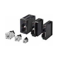
Pulse and analog input modules are now available for the G5 series.
- Features
- Lineup
- Specifications
- Dimensions
- Catalog / Manual / CAD / Software
- Catalog
- Manual
- CAD
English
Global Edition
| Type | Manual Name |
Catalog Number [size] |
Last Update | ||
|---|---|---|---|---|---|
| Manual |
R88M-K[], R88D-KT[]
|
I571-E1-08 [8181KB] |
Jul 03, 2023
20230703 |
0010 030_Manual | R88M-K[], R88D-KT[] AC Servomotors/Servo Drives User’s Manual |
| Instruction Manual |
G5 Series
|
1168418-6J [768KB] |
Nov 18, 2015
20151118 |
0030 031_Instruction Manual | G5 Series AC Servomotor/Servo Drive Instruction Sheet (Safety Precautions) (ENG/JPN/CHI) |
Specifications:809/809093-r88dgt_series.pdf file (04 Aug 2023) |
Accompanying Data:
Omron R88D-GT series Controller PDF Operation & User’s Manual (Updated: Friday 4th of August 2023 04:51:46 AM)
Rating: 4.4 (rated by 3 users)
Compatible devices: ACCURAX G5 -, K3GN, Z500 Series, G9SP-N20S, CJ2 Series, Sysmac NX-PD1000, G9SP Series, E5DC.
Recommended Documentation:
Operation & User’s Manual (Text Version):
(Ocr-Read Summary of Contents of some pages of the Omron R88D-GT series Document (Main Content), UPD: 04 August 2023)
-
13, 11 Items to Check When Unpacking Understanding Servo Drive Model Numbers The model number provides information such as the Servo Drive type, the applicable Servomotor capacity, and the power supply voltage. R88D-GT01H OMNUC G-Series Servo Drive Drive Type T : Three-mode type Power Supply Voltage L : 100 VAC…
-
49, 2-16 2-1 Standard Models 2 Standard Models and Dimensions Note There are separate connectors for power and brakes for 3,000-r/min Servomotors of 50 to 750 W, Flat Servomotors, and Servomotors of 6 kW or higher. Therefore, when a Servomotor with a brake is used, it will require both a Power Cable for a Servomotor…
-
251, Omron R88D-GT series 4-16 4-2 Wiring 4 System Design Motion Control Unit Cable There are special cables for 1-axis and 2-axis Motion Control Unit operation. Select the appropriate cable for the number of axes to be connected. General-purpose Control Cable and Control I/O Connector These cables and connector are used when c…
-
90, Omron R88D-GT series 2-57 2-2 External and Mounting Hole Dimensions 2 Standard Models and Dimensions Decelerators for 3,000-r/min Flat Servomotors Note 1. The standard models have a straight shaft. Note 2. Models with a key and tap are indicated with “J” at the end of the model number (the suffix shown in the box). (Example…
-
32, Omron R88D-GT series 1-11 1-5 Applicable Standards 1 Features and System Configuration The Servo Drives and Servomotors comply with UL 508C (file No. E179149) as long as the following installation conditions 1 and 2 are met. (1) Use the Servo Drive in a pollution degree 1 or 2 environment as defined in IEC 60664-1 (example: inst…
-
224, 3-123 3-5 Servo Relay Units and Cable Specifications 3 Specifications Position Control Unit Cable (XW2Z-@J-A18) This Cable connects a Position Control Unit (CJ1W-NC133) to a Servo Relay Unit (XW2B-20J6- 1B). Cable Models Connection Configuration and Dimensions Wiring Model Length (L) Outer diameter …
-
416, 7-5 7-2 Realtime Autotuning 7 Adjustment Functions Realtime Autotuning Setting Method 1. Stop the Servomotor (i.e., turn the servo OFF). 2. Set the Realtime Autotuning Mode Selection (Pn21) to 1 to 7. The default setting is 1. When the degree of load inertia change is high, set the value to 3 or 6. Us…
-
Omron R88D-GT series User Manual
-
Omron R88D-GT series User Guide
-
Omron R88D-GT series PDF Manual
-
Omron R88D-GT series Owner’s Manuals
Recommended: 4022, 490 Cx Treadmill, 5800RL, MKH 8070, 2927
Operating Impressions, Questions and Answers: