Перейти к содержанию
На чтение 5 мин Просмотров 3.4к.
Содержание
- Переключатель задний Shimano RD-M310 Altus – описание
- Технические характеристики, цена
- Отзывы велосипедистов
- Установка и регулировка заднего переключателя скоростей
Зачастую приходится ставить или менять на велосипеде различные элементы. Они должны быть качественными и надежными. Огромным спросом пользуются корейские и японские производители. Что такое Shimano M310 Altus? Читайте далее.

Переключатель задний Shimano RD-M310 Altus – описание
Задний переключатель от известного в России производителя из Японии.
Обладает следующими преимуществами:
- имеет низкий уровень шума;
- выполнен по современной технологии Double Servo;
- установка с помощью прямого контакта;
- MegaPulley – повышенная износостойкость;
- имеет совместимость с кассетами Shimano и SRAM 8;
- общая вместимость около 43 зубьев.
Был выпущен в 2017 году, имеет гарантию качества на изделие, функционирует с 7 или 8 скоростями. Крепится к транспортному средству с помощью болта. Имеет специальную регулировку натяжения троса, а также способность индексного переключения SIS.
Технические характеристики, цена
- Специальная функциональная лапка Smart Cage;
- В осях шарниров имеются антифрикционные вкладыши;
- Ролики с увеличенным размером;
- Качественный материал изготовления – алюминий, сталь и пластик;
- Широкая рамка;
- Несколько цветовых вариантов.
Цена за изделие варьируется в зависимости от точки продаж. Средняя стоимость от 1250 рублей и выше. Интернет-магазины предлагают более низкую ценовую политику со скидками и подарками.
Отзывы велосипедистов

Катаюсь на велосипеде довольно давно. Знакомый поставил на него переключатель Шимано. Мне нравится, что им легко и просто управлять. В техническом качестве не разбираюсь, но видна работоспособность. Со всеми задачами отлично справляется. Может мой отзыв о данной марке поможет людям в выборе товара.
Оценка:
Анастасия, 29 лет
Пользуюсь транспортом (бюджетным вариантом) с уже встроенным переключателем. Весьма им недоволен, уже имеются небольшие сколы при эксплуатации всего 4 месяца.
Почитав отзывы, решил приобрести товар корейской или японской фирмы, так как их все хвалят. Многие друзья упоминают Шимано. У них также очень хорошие рыболовные снасти. После приобретения продлю отзыв. Думаю, 1450 рублей он стоит.
Оценка:
Никита, 18 лет
Менять подобную деталь на велосипеде рекомендую только на моделях более дорогих. Сам имею 2 разновидности – старую и новую. Старая досталась по наследству. Много раз менял запчасти, но работоспособность не увеличилась.
Смысла в приобретении для него переключателя не вижу. При поломке или желании замены на новом выберу японскую фирму. Они самые известные и качественные. Цена в 1380 рублей в интернете считаю нормой.
Оценка:
Станислав, 22 года
На транспортном средстве не менял еще практически ничего. Но, считаю японские товары более надежными и недорогими. Также товары из Германии показывают отличный функционал. Не думаю, что мне придется модернизировать свой агрегат за 24000 рублей (там стоят детали данных производителей), но страны эти советую.
Оценка:
Михаил, 23 года
Приобретал за 1850 рублей без скидки. Обладает отличной работоспособностью, весьма функционален, заметно качество и надежность. Крепится легко и просто, никаких проблем не возникает. Рекомендую к приобретению.
Оценка:
Павел, 30 лет
Совершаю поездки с таким переключателем, проблем не возникает. Радует его стоимость, производитель и качество. Это самые весомые показатели в данном случае. Рекомендую.
Оценка:
Владимир, 27 лет
Хороший задний переключатель от известной японской марки. Работает отлично, недостатков не заметил. На деталь имеется гарантия, но очень маленькая (всего полгода).
Оценка:
Кирилл, 21 год
Установка и регулировка заднего переключателя скоростей
Установить деталь не составит особого труда даже для новичка. Главное правило после установки – это постоянная смазка и регулировка. Данные действия рекомендуется осуществлять при поднятом заднем колесе. Здесь возможно использование подставки. Различают также обыкновенную и точную настройку.
Вторая имеет место при:
- При покупке и установке новых элементов;
- При замене, регулировке или произведения ремонта цепной передачи;
- При использовании некачественных тросов и рубашек.
Сам же процесс первичной установки и настройки складывается в несколько этапов:
- Этап подготовки. Перед использованием по назначению все элементы переключателя рекомендуется очистить и промыть. Произвести закрепление цепи на звезды. Задние элементы лучше всего дополнительно промазать и проверить их крепление. Рекомендуется вытащить мусор из кассеты, цепи и звезд;
- Освобождение троса. Плотно и крепко вкрутить винты на перебрасывателе и возле манетки. Выполнить вытягивающие движения по отношению к тросу. При возникновении сколов или трещин рекомендуется произвести ремонт, а при отсутствии смазать покупной смазкой;
- Этап крепления троса на звезду. При движении регулировочного винта нужно поставить перебрасыватель в рекомендуемое положение;
- Этап регулировки натяжения троса. Рекомендуется закрепить трос с помощью болта. Путем натягивания его и нажатия на манетку он должен попасть в специальную канавку во избежание дальнейшего сдавливания;
- Этап крепления троса на звезду. Рекомендуется ослабить винт, а цепь перебросить на большую звезду сзади. Крутя педали, нужно произвести выравнивание по отношению к кассете;
- Этап регулирования натяжителя цепи. Здесь цепь крепится на самую малую звезду спереди и самую крупную сзади. Металлический винт закручивать рекомендуется после того, как сам натяжитель будет касаться звезды. Расстояние между элементами нужно сделать примерно 5 миллиметров. Необходимо изменить расположение цепи и проверить ее функционал.
Задний переключатель скоростей Shimano RD-M310 Altus отлично справляется со своими задачами. Такой переключатель подходит для простых прогулок на велосипеде, туристических. Имеет особую прочность, точность и простоту в использовании.
Инструкции и Руководства для Shimano RD-M310.
Мы нашли 100
инструкции доступные для бесплатного скачивания:
Dealer’s Manual, Руководство пользователя


Shimano WH-MT68-R12 Wheel Dealer’s Manual
Бренд:
Shimano
Категория:
Bicycles
Размер:
4 MB
Страниц:
182
Язык(и):
Английский
Оглавление
-
7
IMPORTANT NOTICE
-
8
TO ENSURE SAFETY
-
9
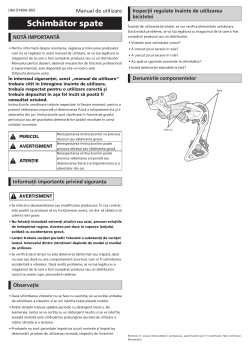
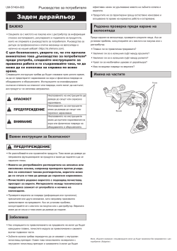
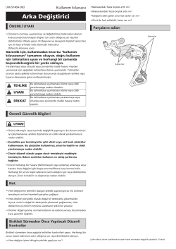
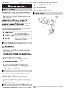
REAR DERAILLEUR
-
10
TO ENSURE SAFETY
-
12
REAR DERAILLEUR FOR MTB/TREKKING
-
12
Installation of the rear derailleur
-
14
Stroke adjustment
-
16
Securing the cable
-
21
SIS adjustment
-
23
Replacing the pulley
-
25
REAR DERAILLEUR FOR ROAD
-
25
Installation of the rear derailleur
-
27
Stroke adjustment
-
30
Securing the cable
-
32
SIS adjustment
-
34
Replacing the pulley
-
35
FRONT DERAILLEUR
-
36
TO ENSURE SAFETY
-
37
FRONT DERAILLEUR FOR MTB/TREKKING
-
37
Installation
-
43
Fixing the cable and adjusting the SIS (Front double)
-
49
Fixing the cable and adjusting the SIS (Front triple)
-
53
FRONT DERAILLEUR FOR ROAD
-
53
Installation
-
55
Fixing the cable and adjusting the SIS (Front double)
-
60
Fixing the cable and adjusting the SIS (Front triple)
-
66
MAINTENANCE
-
67
CHAIN
-
68
TO ENSURE SAFETY
-
71
CHAIN CONNECTING PIN
-
71
Method of use
-
72
QUICK-LINK
-
73
Installing a QUICK-LINK (SM-UG51)
-
75
Installing a QUICK-LINK (SM-CN900-11)
-
76
Removing a QUICK-LINK (SM-CN900-11)
-
77
BRAKE
-
78
TO ENSURE SAFETY
-
82
DISC BRAKE
-
82
Wheel spoke lacing
-
82
Installation of the disc brake rotor
-
87
INSTALLATION (HYDRAULIC DISC BRAKES)
-
87
Installation of the brake lever
-
89
Installation of the brake hose
-
93
Installation of the brake hose (easy hose joint system)
-
103
Replacing the brake hose (easy hose joint system)
-
107
Preventing loosening of frame fixing bolts
-
110
MAINTENANCE (HYDRAULIC DISC BRAKES)
-
110
Brake pad replacement
-
113
Adjustment when the pistons are not operating correctly
-
114
Lever stroke adjustment
-
114
Free stroke adjustment
-
115
Installation of the magnet holder
-
115
Mineral oil replacement
-
116
Adding mineral oil and bleeding air
-
121
INSTALLATION (V-BRAKE BRAKES)
-
121
Installation of the brake lever
-
121
Installing the power modulator
-
122
Installation of V-BRAKE brakes
-
125
MAINTENANCE (V-BRAKE BRAKES)
-
125
Replacement of the cartridge shoe
-
126
BRAKE LEVER WITH SWITCH INTERCHANGEABILITY (V-BRAKE AND HUB ROLLER BRAKES)
-
126
For V-BRAKE (with power modulator) mode
-
126
For Caliper brake/Roller brake
-
127
INSTALLATION (DUAL PIVOT CALIPER BRAKES)
-
130
Arch spring tension adjustment
-
131
MAINTENANCE (DUAL PIVOT CALIPER BRAKES)
-
131
Replacement of the cartridge shoe
-
132
SPECIFICATIONS (CANTILEVER BRAKES)
-
132
Cantilever brakes
-
132
Brake lever
-
133
INSTALLATION (CANTILEVER BRAKES)
-
133
Installation of the brake lever
-
134
Installation of the brake caliper
-
137
Installing SM-CB70
-
138
FRONT CHAINWHEEL
-
139
TO ENSURE SAFETY
-
141
INSTALLATION (CHAINRINGS)
-
141
For ROAD
-
142
For MTB/Trekking
-
143
INSTALLATION (FRONT CHAINWHEEL)
-
143
HOLLOWTECH II / 2 piece crankset
-
148
OCTALINK TYPE
-
149
SQUARE TYPE
-
151
INSTALLATION (PRESS-FIT BOTTOM BRACKET)
-
151
Adapter
-
151
Assembly example
-
152
Installation
-
153
Removal
-
154
PEDALS (SPD-SL PEDALS/SPD PEDALS)
-
155
TO ENSURE SAFETY
-
157
INSTALLATION (SPD PEDALS)
-
157
Engaging the cleats with the pedals
-
157
Releasing the cleats from the pedals
-
159
Attaching the cleats
-
161
Mounting the pedals on the crank arms
-
162
Adjusting the spring tension of the binding
-
162
Cleat replacement
-
163
INSTALLATION (SPD-SL PEDALS)
-
163
Cleat types
-
164
Engaging the cleats with the pedals
-
164
Releasing the cleats from the pedals
-
164
Attaching the cleats
-
165
Mounting the pedals on the crank arms
-
166
Adjusting the spring tension of the binding
-
166
Cleat replacement
-
167
Replacement of the body cover
-
167
Maintenance of the axle units
-
167
Mounting the reflectors (optional)
-
168
HUB DYNAMO
-
169
TO ENSURE SAFETY
-
171
INSTALLATION (HUB DYNAMO)
-
171
Installation of the disc brake rotor
-
171
Installation of the front wheel
-
175
CONNECTION OF THE CABLES
-
175
For E2 type
-
176
For J2 type
-
177
For J2-A type
-
179
Note on the connection of the cables
-
179
Checking the light illumination
-
180
MULTIPLE FREEWHEEL
-
181
INSTALLATION (MULTIPLE FREEWHEEL)
-
181
Installation of the freewheel
Открыть в новой вкладке

Shimano RD-TZ50 Dérailleur arrière Manuel utilisateur
Бренд:
Shimano
Категория:
Bicycle accessories
Размер:
7 MB
Страниц:
155
Язык(и):
Французский
Оглавление
-
9
MISE EN GARDE IMPORTANTE
-
10
POUR VOTRE SÉCURITÉ
-
14
DÉRAILLEUR ARRIÈRE POUR VTT/TREKKING
-
14
Installation du dérailleur arrière
-
14
Type standard
-
14
Type à boîtier
-
15
Réglage de la course
-
15
Réglage supérieur
-
15
Réglage inférieur
-
16
Longueur de chaîne
-
17
Fixation du câble
-
17
Découpe de la gaine
-
18
Raccordement et fixation du câble
-
19
Utilisation de la vis B de réglage de tension
-
20
Réglage SIS
-
22
Remplacement de la poulie
-
22
Galet de guidage
-
22
Galet de tension
-
23
DÉRAILLEUR ARRIÈRE POUR ROUTE
-
23
Installation du dérailleur arrière
-
23
Type standard
-
24
Type à boîtier
-
24
Réglage de la course
-
24
Réglage supérieur
-
24
Réglage inférieur
-
24
Longueur de chaîne
-
27
Fixation du câble
-
27
Découpe de la gaine
-
27
Raccordement et fixation du câble
-
28
Utilisation de la vis B de réglage de tension
-
28
Réglage SIS
-
29
Remplacement de la poulie
-
31
POUR VOTRE SÉCURITÉ
-
32
DÉRAILLEUR AVANT POUR VTT/TREKKING
-
32
Installation
-
32
Type à collier
-
34
Type E
-
35
Type E (modèles sans plaque de boîtier de pédalier)
-
36
Type à montage direct
-
37
Fixation du câble et réglage du SIS (double avant)
-
37
Réglage inférieur
-
38
Fixation du câble
-
41
Réglage de la tension du câble
-
42
Réglage supérieur
-
42
Tableau de recherche des pannes
-
43
Fixation du câble et réglage du SIS (triple avant)
-
43
Réglage inférieur
-
43
Fixation du câble
-
44
Réglage supérieur
-
44
Réglage de la tension du câble
-
45
Tableau de recherche des pannes
-
46
DÉRAILLEUR AVANT POUR ROUTE
-
46
Installation
-
47
Fixation du câble et réglage du SIS (double avant)
-
47
Fonctionnement du levier et point d’indice de câble
-
48
Fixation du câble
-
49
Réglage inférieur
-
49
Réglage de la tension du câble
-
50
Réglage supérieur
-
51
Tableau de recherche des pannes
-
51
Fixation du câble et réglage du SIS (triple avant)
-
51
Fonctionnement du levier et point d’indice de câble
-
52
Réglage inférieur
-
53
Fixation du câble
-
53
Réglage supérieur
-
54
Réglage de la tension du câble
-
55
Tableau de recherche des pannes
-
56
ENTRETIEN
-
56
Type brasé
-
56
Type à collier
-
56
Type E
-
56
Type à montage direct
-
58
POUR VOTRE SÉCURITÉ
-
61
BROCHE DE RACCORDEMENT DE CHAÎNE
-
61
Méthode
-
62
QUICK-LINK
-
63
Installer un QUICK-LINK (SM-UG51)
-
64
Installer un QUICK-LINK (SM-CN900-11)
-
64
Retrait d’un QUICK-LINK (SM-CN900-11)
-
66
POUR VOTRE SÉCURITÉ
-
70
FREIN A DISQUE
-
70
Croisement des rayons
-
70
Installation du disque de frein à disque
-
70
Type à verrouillage central
-
72
Type à 5 boulons (avec rondelles-frein)
-
73
Type à 6 boulons
-
73
Type à 6 boulons (avec rondelles-frein)
-
74
INSTALLATION (FREINS A DISQUES HYDRAULIQUES)
-
74
Montage du levier de frein
-
75
Installation de la durite de frein
-
78
À l’extrémité de l’étrier (type Banjo)
-
78
À l’extrémité de l’étrier (type droit)
-
79
Installation de la durite de frein (système de raccord facile de la durite de frein)
-
79
Aperçu du système de raccord facile de la durite de frein (pour VTT)
-
81
Aperçu du système de raccord facile de la durite de frein (pour vélo ROUTE)
-
83
Coupe de la durite
-
85
Remplacement de la durite de frein (système de raccord facile de la durite de frein)
-
85
Pour les VTT BH
-
86
Pour les vélos ROUTE
-
87
Installation des étriers et fixation du flexible
-
88
Type de montage standard International
-
89
Système Postmount
-
90
Prévention du desserrage des boulons de fixation du cadre
-
90
Méthode du bouchon
-
90
Méthode du câble
-
91
Fixation du câble
-
92
ENTRETIEN (FREINS A DISQUES HYDRAULIQUES)
-
92
Remplacement des plaquettes de frein
-
94
Réglage en cas de dysfonctionnement des pistons
-
94
Réglage de la course du levier
-
95
Réglage d’attaque
-
95
Installation du support de l’aimant
-
95
Remplacement d’huile minérale
-
95
Rajouter de l’huile minérale et purger l’air
-
100
INSTALLATION (FREINS V-BRAKE)
-
100
Montage du levier de frein
-
100
Installation du modulateur de puissance
-
101
Installation des freins V-BRAKE
-
104
ENTRETIEN (FREINS V-BRAKE)
-
104
Remplacement des patins à cartouche
-
105
(FREINS V-BRAKE ET À TAMBOUR)
-
105
Mode pour V-BRAKE (avec modulateur)
-
105
Pour frein à étrier/frein à tambour
-
106
INSTALLATION (ÉTRIER DE FREIN À DOUBLE PIVOT)
-
108
Réglage de la tension du ressort de l’arc
-
109
ENTRETIEN (ÉTRIER DE FREIN À DOUBLE PIVOT)
-
109
Remplacement du patin à cartouche
-
111
SPÉCIFICATIONS (FREINS CANTILEVER)
-
111
Frein cantilever
-
111
Levier de frein
-
112
INSTALLATION (FREINS CANTILEVER)
-
112
Montage du levier de frein
-
112
Installation de l’étrier de frein
-
115
Installation du SM-CB
-
115
Méthode de réglage
-
117
POUR VOTRE SÉCURITÉ
-
119
INSTALLATION (PLATEAUX)
-
119
Pour les vélos ROUTE
-
119
Double plateau
-
120
Triple plateau
-
120
Pour les VTT / Trekking
-
120
Triple plateau
-
121
INSTALLATION (PLATEAU AVANT)
-
121
HOLLOWTECH II / Pédalier en 2 parties
-
121
Installation du pédalier
-
123
Disposition des entretoises (pour VTT/Trekking)
-
125
TYPE OCTALINK
-
125
Installation du boîtier de pédalier
-
125
Montage du pédalier
-
126
TYPE SQUARE
-
126
Installation du boîtier de pédalier
-
126
Montage du pédalier
-
127
INSTALLATION (BOÎTIER DE PÉDALIER PRESS-FIT)
-
127
Adaptateur
-
127
Exemple de montage
-
128
Installation
-
128
Démontage
-
131
POUR VOTRE SÉCURITÉ
-
133
INSTALLATION (PÉDALES SPD)
-
133
Enclenchement des cales sur les pédales
-
133
Déclencher les cales
-
133
Cales à déclenchement unidirectionnel : SM-SH51 (noir)
-
134
Cales à déclenchement multidirectionnel : SM-SH56 (argent, or)
-
134
Fixation des cales
-
135
Réglage de la position de la cale
-
136
Joint étanche
-
136
Montage des pédales sur les manivelles
-
137
Réglage de la tension de ressort de la fixation
-
137
Remplacement d’une cale
-
138
INSTALLATION (PÉDALES SPD-SL)
-
138
Types de cale
-
139
Enclenchement des cales sur les pédales
-
139
Déclencher les cales
-
139
Fixation des cales
-
140
Réglage de la position de la cale
-
140
Fixation des pédales sur les manivelles
-
141
Réglage de la tension de ressort de la fixation
-
141
Remplacement d’une cale
-
141
Remplacement du cache de corps
-
141
Entretien des unités d’axe
-
141
Fixation des réflecteurs (en option)
-
143
POUR VOTRE SÉCURITÉ
-
145
INSTALLATION (MOYEU-DYNAMO)
-
145
Installation du disque de frein à disque
-
145
Installation de la roue avant
-
145
Pour type à blocage rapide
-
146
Pour type à écrous
-
147
Pour le type E-THRU
-
148
RACCORDEMENT DES CÂBLES
-
148
Pour type E
-
149
Pour type J
-
150
Pour type J2-A
-
151
Remarque concernant la branchement des câbles
-
152
Vérification de l’éclairage
-
154
INSTALLATION (ROUE LIBRE MULTIVITESSE)
-
154
Montage de la roue-libre
Открыть в новой вкладке


Перейти к содержанию
На чтение 5 мин Просмотров 3.3к.
Содержание
- Переключатель задний Shimano RD-M310 Altus – описание
- Технические характеристики, цена
- Отзывы велосипедистов
- Установка и регулировка заднего переключателя скоростей
Зачастую приходится ставить или менять на велосипеде различные элементы. Они должны быть качественными и надежными. Огромным спросом пользуются корейские и японские производители. Что такое Shimano M310 Altus? Читайте далее.
Задний переключатель от известного в России производителя из Японии.
Обладает следующими преимуществами:
- имеет низкий уровень шума;
- выполнен по современной технологии Double Servo;
- установка с помощью прямого контакта;
- MegaPulley – повышенная износостойкость;
- имеет совместимость с кассетами Shimano и SRAM 8;
- общая вместимость около 43 зубьев.
Был выпущен в 2017 году, имеет гарантию качества на изделие, функционирует с 7 или 8 скоростями. Крепится к транспортному средству с помощью болта. Имеет специальную регулировку натяжения троса, а также способность индексного переключения SIS.
Технические характеристики, цена
- Специальная функциональная лапка Smart Cage;
- В осях шарниров имеются антифрикционные вкладыши;
- Ролики с увеличенным размером;
- Качественный материал изготовления – алюминий, сталь и пластик;
- Широкая рамка;
- Несколько цветовых вариантов.
Цена за изделие варьируется в зависимости от точки продаж. Средняя стоимость от 1250 рублей и выше. Интернет-магазины предлагают более низкую ценовую политику со скидками и подарками.
Отзывы велосипедистов
Катаюсь на велосипеде довольно давно. Знакомый поставил на него переключатель Шимано. Мне нравится, что им легко и просто управлять. В техническом качестве не разбираюсь, но видна работоспособность. Со всеми задачами отлично справляется. Может мой отзыв о данной марке поможет людям в выборе товара.
Оценка:
Анастасия, 29 лет
Пользуюсь транспортом (бюджетным вариантом) с уже встроенным переключателем. Весьма им недоволен, уже имеются небольшие сколы при эксплуатации всего 4 месяца.
Почитав отзывы, решил приобрести товар корейской или японской фирмы, так как их все хвалят. Многие друзья упоминают Шимано. У них также очень хорошие рыболовные снасти. После приобретения продлю отзыв. Думаю, 1450 рублей он стоит.
Оценка:
Никита, 18 лет
Менять подобную деталь на велосипеде рекомендую только на моделях более дорогих. Сам имею 2 разновидности – старую и новую. Старая досталась по наследству. Много раз менял запчасти, но работоспособность не увеличилась.
Смысла в приобретении для него переключателя не вижу. При поломке или желании замены на новом выберу японскую фирму. Они самые известные и качественные. Цена в 1380 рублей в интернете считаю нормой.
Оценка:
Станислав, 22 года
На транспортном средстве не менял еще практически ничего. Но, считаю японские товары более надежными и недорогими. Также товары из Германии показывают отличный функционал. Не думаю, что мне придется модернизировать свой агрегат за 24000 рублей (там стоят детали данных производителей), но страны эти советую.
Оценка:
Михаил, 23 года
Приобретал за 1850 рублей без скидки. Обладает отличной работоспособностью, весьма функционален, заметно качество и надежность. Крепится легко и просто, никаких проблем не возникает. Рекомендую к приобретению.
Оценка:
Павел, 30 лет
Совершаю поездки с таким переключателем, проблем не возникает. Радует его стоимость, производитель и качество. Это самые весомые показатели в данном случае. Рекомендую.
Оценка:
Владимир, 27 лет
Хороший задний переключатель от известной японской марки. Работает отлично, недостатков не заметил. На деталь имеется гарантия, но очень маленькая (всего полгода).
Оценка:
Кирилл, 21 год
Установка и регулировка заднего переключателя скоростей
Установить деталь не составит особого труда даже для новичка. Главное правило после установки – это постоянная смазка и регулировка. Данные действия рекомендуется осуществлять при поднятом заднем колесе. Здесь возможно использование подставки. Различают также обыкновенную и точную настройку.
Вторая имеет место при:
- При покупке и установке новых элементов;
- При замене, регулировке или произведения ремонта цепной передачи;
- При использовании некачественных тросов и рубашек.
Сам же процесс первичной установки и настройки складывается в несколько этапов:
- Этап подготовки. Перед использованием по назначению все элементы переключателя рекомендуется очистить и промыть. Произвести закрепление цепи на звезды. Задние элементы лучше всего дополнительно промазать и проверить их крепление. Рекомендуется вытащить мусор из кассеты, цепи и звезд;
- Освобождение троса. Плотно и крепко вкрутить винты на перебрасывателе и возле манетки. Выполнить вытягивающие движения по отношению к тросу. При возникновении сколов или трещин рекомендуется произвести ремонт, а при отсутствии смазать покупной смазкой;
- Этап крепления троса на звезду. При движении регулировочного винта нужно поставить перебрасыватель в рекомендуемое положение;
- Этап регулировки натяжения троса. Рекомендуется закрепить трос с помощью болта. Путем натягивания его и нажатия на манетку он должен попасть в специальную канавку во избежание дальнейшего сдавливания;
- Этап крепления троса на звезду. Рекомендуется ослабить винт, а цепь перебросить на большую звезду сзади. Крутя педали, нужно произвести выравнивание по отношению к кассете;
- Этап регулирования натяжителя цепи. Здесь цепь крепится на самую малую звезду спереди и самую крупную сзади. Металлический винт закручивать рекомендуется после того, как сам натяжитель будет касаться звезды. Расстояние между элементами нужно сделать примерно 5 миллиметров. Необходимо изменить расположение цепи и проверить ее функционал.
Задний переключатель скоростей Shimano RD-M310 Altus отлично справляется со своими задачами. Такой переключатель подходит для простых прогулок на велосипеде, туристических. Имеет особую прочность, точность и простоту в использовании.

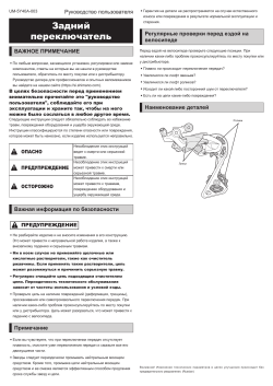
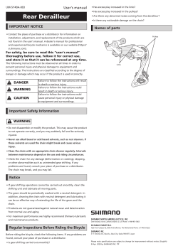
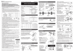
Rear Derailleur
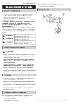
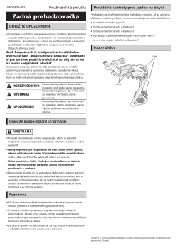
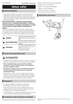
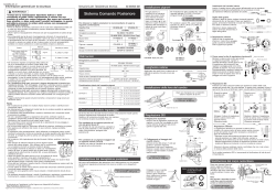
IMPORTANT NOTICE
•
Contact the place of purchase or a distributor for information on
installation, adjustment, and replacement of the products which are
not found in the user’s manual. A dealer’s manual for professional
and experienced bicycle mechanics is available on our website (https://
si.shimano.com).
For safety, be sure to read this user’s manual
thoroughly before use, follow it for correct use,
and store it so that it can be referenced at any time.
The following instructions must be observed at all times in order to
prevent personal injury and physical damage to equipment and
surroundings. The instructions are classified according to the degree of
danger or damage which may occur if the product is used incorrectly.
DANGER
Failure to follow the instructions will result
in death or serious injury.
WARNING
Failure to follow the instructions could
result in death or serious injury.
CAUTION
Failure to follow the instructions could
cause personal injury or physical damage
to equipment and surroundings.
Important safety information
WARNING
•
Do not disassemble or modify the product. This may cause the product
to not operate correctly, and you may suddenly fall and be seriously
injured.
•
Never use alkali- or acid-based solvents such as rust cleaners. If
those solvents are used the chain might break and cause
serious injury.
•
Clean the chain with an appropriate chain cleaner regularly.
Intervals between maintenance depend on the use and riding
circumstances.
•
Check the chain for any damage (deformation or cracking), skipping,
or other abnormalities such as unintended gear shifting. If any
problems are found, consult your place of purchase or a distributor.
The chain may break, and you may fall.
Notice
•
If gear shifting operations do not feel smooth, wash the shifting unit
and lubricate all moving parts.
•
The sprockets should be periodically washed with a neutral detergent.
In addition, cleaning the chain with neutral detergent and lubricating
it can be an effective way of extending the life of the sprocket and
the chain.
•
Products are not guaranteed against natural wear and deterioration
from normal use and aging.
•
For maximum performance we highly recommend SHIMANO
lubricants and maintenance products.
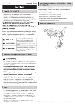
Regular inspections before riding the bicycle
Before riding the bicycle, check the following items. If any problems are
found, consult your place of purchase or a distributor.
•
Is gear shifting carried out smoothly?
•
Has excess play increased in the links?
•
Has excess play increased in the pulleys?
•
Are there any abnormal noises coming from the derailleur?
•
Is there any noticeable damage on the chain?
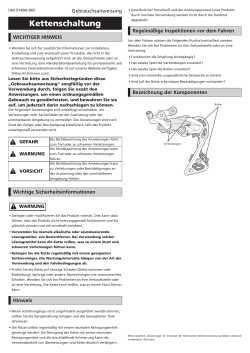
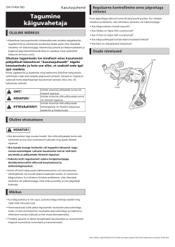
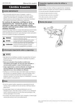
Names of parts
Link
Pulley
UM-5Y40A-004
User’s Manual
Please note: specifications are subject to change for improvement without notice. (English)
© Feb. 2022 by SHIMANO INC. ITP
One Holland, Irvine, California 92618, U.S.A. Phone: +1-949-951-5003
High Tech Campus 92, 5656 AG Eindhoven, The Netherlands Phone: +31-402-612222
3-77 Oimatsu-cho, Sakai-ku, Sakai City, Osaka 590-8577, Japan

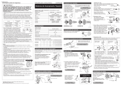
idfire Plus Lever (2-Finger / For V-BRAKE)
ST-M310-8R2/L2
Silver Version
ST-M310-8R2/L2
Y6UH98010 R.H. Indicator Unit B
Y6UJ98010 L.H. Indicator Unit A
2Y6UH98030 Reach Adjusting Screw (M4 x 14.5) & Spring
3Y8UM98010 Brake Cable Adjusting Bolt & Nut A
4Y6PZ98070 Shifting Cable Adjusting Bolt Unit A
5Y6CD33000 Inner Hole Cap AA
6Y6TB9806
Main Lever Cover & Fixing Scre
A
7Y6UD89000 Clamp Bolt (M6 x 17.5)
A: Same parts. Mar.-2011-3258
© Shimano Inc. I
Absence of mark indicates non-interchangeability.
Specifications are subject to change without notice.
INTERCHANGE-
ABILITY
SL—M31
1
B: Parts are usable, but differ in materirals, appearance, finish, size, etc.
CODE NO.
SHIMANO
ITEM
NO. DESCRIPTION
ST—M360—2A
ST—EF51—2A
For Right Hand
For Left Hand
1
1
2
2
3
3
6
4
4
6
7
5
5
7
idfire Plus Lever (4-Finger)
ST-M310-8R4/L4
Silver Version
ST-M310-8R4/L4
Y6UH98010 R.H. Indicator Unit B
Y6UJ98010 L.H. Indicator Unit A
2Y6UH98030 Reach Adjusting Screw (M4 x 14.5) & Spring
Y8TS98010 R.H. Adjustment Block & Fixing Screw A A
Y8TS98020 L.H. Adjustment Block & Fixing Screw A A
4Y8UM98010 Brake Cable Adjusting Bolt & Nut AA
5Y6PZ98070 Shifting Cable Adjusting Bolt Unit A
6Y6CD33000 Inner Hole Cap AA
7Y6TB9806
Main Lever Cover & Fixing Scre
A
8Y6UD89000 Clamp Bolt (M6 x 17.5)
A: Same parts. Mar.-2011-3259
© Shimano Inc. I
Absence of mark indicates non-interchangeability.
Specifications are subject to change without notice.
ABILITY
SL—M31
INTERCHANGE-
B: Parts are usable, but differ in materirals, appearance, finish, size, etc.
CODE NO.
SHIMANO
ITEM
NO. DESCRIPTION
3
1
ST—M360—4A
ST—EF51—4A
For Right Hand
For Left Hand
1
1
2
2
33
4
4
55
6
6
77
8
8

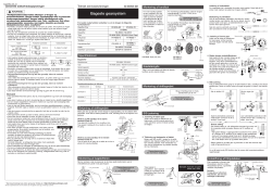
Lock ring
5 mm Allen key
Dropout tab
B-tension adjustment screw
General Safety Information
WARNING
• If it is necessary to adjust the length of the chain due to a
change in the number of sprocket teeth, make the cut at
some other place than the place where the chain has been
joined using a reinforced connecting pin or an end pin. The
chain will be damaged if it is cut at a place where it has
been joined with a reinforced connecting pin or an end pin.
• Check that the tension of the chain is correct and that the chain is not damaged. If the
tension is too weak or the chain is damaged, the chain should be replaced. If this is not
done, the chain may break and cause serious injury.
•Obtain and read the service instructions carefully prior to installing the parts. Loose,
worn or damaged parts may cause the bicycle to fall over and serious injury may occur as a
result. We strongly recommend only using genuine Shimano replacement parts.
•Obtain and read the service instructions carefully prior to installing the parts. If
adjustments are not carried out correctly, the chain may come off and this may cause you to
fall off the bicycle which could result in serious injury.
• Read these Technical Service Instructions carefully, and keep them in a safe place for later
reference.
Note
• If gear shifting operations do not feel smooth, wash the derailleur and lubricate all moving
parts.
• If the amount of looseness in the links is so great that adjustment is not possible, you should
replace the derailleur.
• You should periodically clean the derailleur and lubricate all moving parts (mechanism and
pulleys).
• If gear shifting adjustment cannot be carried out, check the degree of parallelism at the rear
end of the bicycle. Also check if the cable is lubricated and if the outer casing is too long or
too short.
• If you hear abnormal noise as a result of looseness in a pulley, you should replace the
pulley.
• If the wheel becomes stiff and difficult to turn, you should lubricate it with grease.
• Do not apply any oil to the inside of the hub, otherwise the grease will come out.
• You should periodically wash the sprockets in a neutral detergent and then lubricate them
again. In addition, cleaning the chain with neutral detergent and lubricating it can be a
effective way of extending the useful life of the sprockets and the chain.
• If the chain keeps coming off the sprockets during use, replace the sprockets and the chain.
• Always be sure to use the sprocket set bearing the same group marks. Never use in
combination with a sprocket bearing a different group mark.
• Use a frame with internal cable routing is strongly discouraged as it
has tendencies to impair the SIS shifting function due to its high cable
resistance.
• Use an outer casing which still has some length to spare even when
the handlebars are turned all the way to both sides. Furthermore,
check that the shifting lever does not touch the bicycle frame when the
handlebars are turned all the way.
• Grease the inner cable and the inside of the outer casing before use
to ensure that they slide properly.
• Operation of the levers related to gear shifting should be made only
when the front chainwheel is turning.
• Parts are not guaranteed against natural wear or deterioration resulting from normal use.
• For maximum performance we highly recommend Shimano lubricants and maintenance
products.
• For any questions regarding methods of installation, adjustment, maintenance or operation,
please contact a professional bicycle dealer.
Chain toolChain
9-speed super narrow chain
such as
CN-7701 / CN-HG93
8- / 7- / 6-speed narrow
chain such as
CN-HG50 / CN-HG40
Reinforced
connecting pin
TL-CN32 / TL-CN27
TL-CN32 / TL-CN27
g
a
—
18
T
—
S
H
I
M
A
N
O
H
Y
P
E
R
G
L
I
D
E
C
a
g
—
1
5
T
a
g
—
1
3
T
Group marks
Reinforced Connecting Pin
End Pin Link Pin
One Holland, Irvine, California 92618, U.S.A. Phone: +1-949-951-5003
Industrieweg 24, 8071 CT Nunspeet, The Netherlands Phone: +31-341-272222 3-77 Oimatsu-cho, Sakai-ku, Sakai-shi, Osaka 590-8577, Japan
* Service Instructions in further languages are available at : http://techdocs.shimano.com
Please note: specifications are subject to change for improvement without notice. (English)
©Nov.2010 by Shimano Inc. XBC IZM Printed in Singapore.
This service instruction explains how to use and maintain the Shimano bicycle parts which have
been used on your new bicycle. For any questions regarding your bicycle or other matters which
are not related to Shimano parts, please contact the place of purchase or the bicycle manufacturer.
Te c h nica l Ser vic e Inst r uct i ons SI-6UH0A-001
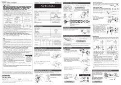
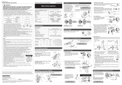
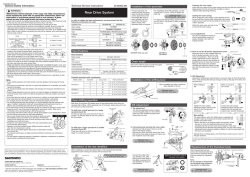
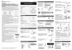
Rear Drive System
Specifications
Model number
Typ e
Total capacity
Largest sprocket
Smallest sprocket
Front chainwheel tooth difference
Applicable front chainwheel
(chainring tooth configuration)
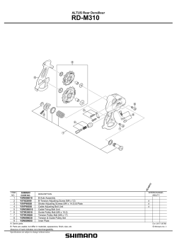
RD-M310
Rear Derailleur
Smart Cage
43T
34T
11T
20T
FC-M361 / M311 (48-38-28T / 42-32-22T)
FC-M361-8 / M311-8 (42-32-22T)
Model number
CS-HG31-8
Tooth combination
11, 13, 15, 17, 20, 23, 26, 30T
11, 13, 15, 18, 21, 24, 28, 32T
11, 13, 15, 17, 20, 23, 26, 34T
Cassette sprocket tooth combination
Sprockets
8
8
8
Group name
an
aw
ao
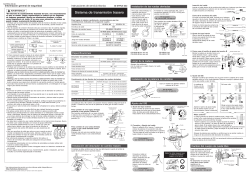
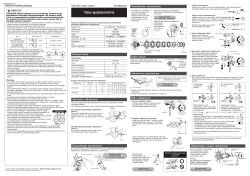
Installation of the rear derailleur
When installing, be careful that deformation is not caused by the B-tension
adjustment screw coming into contact with the dropout tab.
Bracket spindle tightening torque:
8 — 10 N·m {70 — 86 in. lbs.}
Replacement of the freewheel body
After removing the hub axle,
remove the freewheel body fixing
bolt (inside the freewheel body),
and then replace the freewheel
body.
Note:
Do not attempt to disassemble
the freewheel body, because it
may result in a malfunction.
Freewheel body Freewheel body fixing bolt
Freewheel body washer
10 mm Allen key
(TL-WR37)
Disassembly
Assembly
Tightening torque:
35 — 50 N·m {305 — 434 in. lbs.}
For the best SIS performance, periodically lubricate all power-transmission
parts.
5. SIS Adjustment
Operate the shifting lever several times to move the chain to the 2nd sprocket.
Then, while pressing the lever just enough to take up the play in the lever, turn
the crank arm.
When shifting to
3rd
Tighten the outer cable adjusting
barrel until the chain returns to
the 2nd sprocket. (clockwise)
Loosen the outer casing
adjustment barrel until the chain
touches the 3rd sprocket and
makes noise. (counter clockwise)
Outer casing
adjustment
barrel
Best setting
The best setting is when the shifting lever is operated just
enough to take up the play and the chain touches the 3rd
sprocket and makes noise.
*Return the lever to its original position (the position where
the lever is at the 2nd sprocket setting and it has been
released) and then turn the crank arm clockwise. If the chain
is touching the 3rd sprocket and making noise, turn the outer casing
adjustment barrel clockwise slightly to tighten it until the noise stops and
the chain runs smoothly.
Operate lever to change gears, and check that no noise occurs in any of
the gear positions.
Tightening torque :
5 — 7 N·m {44 — 60 in. lbs.} Groove
Connect the cable to the
rear derailleur and, after
taking up the initial slack in
the cable, re-secure to the
rear derailleur as shown in
the illustration.
Pull
Note: Be sure that the cable is
securely in the groove.
Allen key tightening torque:
6 — 8 N·m {53 — 69 in. lbs.}
5 mm Allen key
Use a handlebar grip with a maximum
outer diameter of 36 mm.
Mounting the shifting lever
Outer line of
smallest sprocket
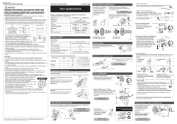
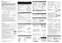
Guide pulley To p a d ju st m en t
screw
1. Top adjustment
Turn the top adjustment screw to adjust
so that the guide pulley is in line with the
outer line of the smallest sprocket when
looking from the rear.
SIS Adjustment
Cutting the outer casing
When cutting the outer casing, cut the opposite end to
the end with the marking. After cutting the outer casing,
make the end round so that the inside of the hole has a
uniform diameter.
Attach the same outer end cap to the
cut end of the outer casing. Outer end cap
Inserting the inner cable
Insert the inner cable into the outer casing from the end with the marking on it.
Apply grease from the end with the marking in order to maintain
cable operating efficiency.
Marking
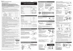
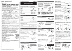
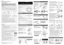
4. How to use the B-tension adjustment screw
Mount the chain on the smallest chainring
and the largest sprocket, and turn the
crank arm backward. Then turn the B-
tension adjustment screw to adjust the
guide pulley as close to the sprocket as
possible but not so close that it touches.
Next, set the chain to the smallest
sprocket and repeat the above to make
sure that the pulley does not touch the
sprocket.
Largest sprocket
Smallest sprocket
Chain
Largest chainringLargest chainring
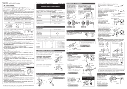
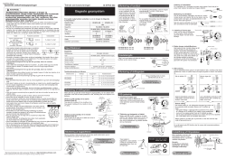
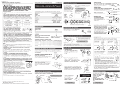
Gear shifting operation
Both lever (A) and lever (B) always return to the initial position when they are
released after shifting. When operating one of the levers, always be sure to turn
the crank arm at the same time.
To shift fro m a sm a l l sp ro cket to a
larger sprocket (Lever A)
To shift one step only, press lever (A) to
the (1) position. To shift two steps at
one time, press to the (2) position.
Lever (A) initial position
To shift fro m a la r g e sp ro cket to a
smaller sprocket (Lever B)
Press lever (B) once to shift one step
from a larger to a smaller sprocket.
Add 2 links (with the chain on both the largest
sprocket and the largest chainring)
Chain length
3. Low adjustment
Turn the low adjustment screw so
that the guide pulley moves to a
position directly in line with the
largest sprocket.
Largest sprocket
Guide pulley
Low adjustment
screw
B-tension
adjustment screw
When no sound at
all is heard
Outer casing
adjustment
barrel
SI-6UH0A-001-00
“Maintenance interval depends on the usage and riding circumstances.
Clean regularly the chain with an appropriate chaincleaner. Never use
alkali based or acid based solvents such as rust cleaners. If those
solvent be used chain might break and cause serious injury.”
• Check that the wheels are fastened securely before riding the bicycle. If the wheels are
loose in any way, they may come off the bicycle and serious injury may result.
• Use the reinforced connecting pin only for connecting the narrow type of chain.
• There are two different types of reinforced connecting pins available. Be sure to check the
table below before selecting which pin to use. If connecting pins other than reinforced
connecting pins are used, or if a reinforced connecting pin or tool which is not suitable for
the type of chain is used, sufficient connection force may not be obtained, which could
cause the chain to break or fall off.
Install the inner hole cover by turning it as shown in
the illustration until it stops.
Do not turn it any further than this, otherwise it may
damage the screw thread.
Lever (B)
Inner cable
Inner hole cover
Inner hole cover
2. Connecting and securing the inner cable
Operate lever (B) 7 times or more, and check on
the indicator that the lever is at the highest
position. Then remove the inner hole cover and
connect the inner cable.
For each sprocket, the
surface that has the group
mark should face outward
and be positioned so that
the triangle (U) mark on
each sprocket and the A
part (where the groove
width is wide) of the
freewheel body are aligned.
For installation of the HG sprockets, use the
special tool (TL-LR15 / LR10) to tighten the
lock ring.
To replace the HG sprockets, use the special
tool (TL-LR15 / LR10) and TL-SR21 to remove
the lock ring.
The groove is
wide at one
place only.
Umark
Tightening torque:
30 — 50 N·m {261 — 434 in. lbs.}
Lock ring
To ol
(TL-SR21)
Disassembly
TL-LR15/LR10
Installation of the sprockets
Lever (B)
Adjusting the grip width
It is recommended that you adjust the grip
widths of the levers to the most comfortable
widths for gear shifting and braking.
A:Becomes narrower
B:Becomes wider
Rapidfire Plus
Outer casing
Rear derailleur
Ty p e
Freehub
Gears
Cassette sprocket
Chain
Bottom bracket guide
ST-M310-8R
SP40
RD-M310
Smart Cage
FH-RM30-8
8
CS-HG31-8
CN-HG50 / CN-HG40
SM-SP18 / SM-BT18
In order to realize the best performance, we recommend that the
following combination be used.

General Safety Information
WARNING
Right
Left
Rapidfire Plus
Outer casing
Front derailleur
Front chainwheel
Bottom bracket
Chain
Bottom bracket cable guide
SIS 8-gears
SIS 3-gears
ST-M310-L
OT-SP40
FD-M311 / FD-M310 / FD-M190-3 / FD-M190A / FD-M191
FC-M361 / FC-M361-8 / FC-M311 / FC-M311-8 / FC-M171 / FC-M131
BB-UN26 (-K) / BB-ES25 (-K)
CN-HG50 / CN-HG40
SM-SP17 / SM-BT17 / SM-SP18 / SM-BT18
Gears
In order to realize the best performance, we recommend that the following combination be used.
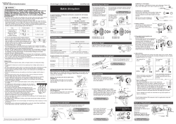
Te ch ni ca l S er v ic e In str uct io n s SI-6UJ0A-002
One Holland, Irvine, California 92618, U.S.A. Phone: +1-949-951-5003
Industrieweg 24, 8071 CT Nunspeet, The Netherlands Phone: +31-341-272222 3-77 Oimatsu-cho, Sakai-ku, Sakai-shi, Osaka 590-8577, Japan
* Service Instructions in further languages are available at : http://techdocs.shimano.com
Please note: specifications are subject to change for improvement without notice. (English) © Feb. 2011 by Shimano Inc. XBC IZM Printed in Singapore.
This service instruction explains how to use and maintain the Shimano bicycle parts which have been used on your new
bicycle. For any questions regarding your bicycle or other matters which are not related to Shimano parts, please contact
the place of purchase or the bicycle manufacturer.
To shift from a small chainring to a larger chainring
(Lever A)
When lever (A) is
pressed once, there is a
shift of one step from a
small chainring to a
larger chainring.
Example:
from intermediate
chainring to largest
chainring.
To shift from a large chainring to a smaller chainring
(Lever B)
When lever (B) is
pressed once, there is a
shift of one step from a
large chainring to a
smaller chainring.
Example:
from largest chainring to
intermediate chainring.
Gear shifting operation
Both lever (A) and lever (B) always return to the initial position
when they are released after shifting.
When operating one of the levers, always be sure to turn the
crank arm at the same time.
Lever (A) initial position
Lever (B)
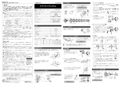
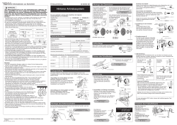
Installation of the Front Derailleur,
Bottom Bracket and Front Chainwheel
Chainwheel
(largest chainring)
Chain guide
Use the special tools (TL-UN65 and TL-UN74-S) to install the
bottom bracket 1and the front derailleur so that they face as
shown in the illustration. Install the adapter 2, and then use
the cotterless crank extractor (TL-FC10) to install the front
chainwheel.
Adjust and then install the front derailleur as shown in the
illustration. Do not remove the Pro-Set alignment block at this
time.
The level section of the chain
guide outer plate should be
directly above and parallel to the
largest chainring. Secure using a
5 mm Allen key.
Adapter / bottom bracket tightening torque:
50 — 70 N·m {435 — 608 in. lbs.}
Front chainwheel tightening torque:
35 — 50 N·m {305 — 435 in. lbs.}
Gear teeth
should come
within this range
Pro-Set gauge
Pro-Set alignment block
1Bottom Bracket2Adapter
Front Derailleur
3Front Chainwheel
Tightening torque :
5 — 7 N·m {44 — 60 in. lbs.}
Chain length
Add 2 links (with the chain on
both the largest sprocket and
the largest chainring)
Largest sprocket Largest chainring
Chain
Use a 5 mm Allen key to tighten the wire fixing bolt.
Cut off the excess length of inner cable and then install the inner end
cap.
< FD-M310/ M191 / M190-3/ M190A > < FD-M311 >
Tightening torque :
5 — 7 N·m {44 — 60 in. lbs.}
Note:
Pass the cable through as
shown in the illustration.
After taking up the initial slack in the cable, re-secure to the front
derailleur as shown in the illustration.
Normal type Top route type
Pull
Pull
4. Adjustment of the intermediate chainring
When carrying out adjustment, set the chain to the largest sprocket,
and at the front, set the chain to the intermediate chainring. Adjust
using the outer casing adjustment barrel so that the clearance
between the chain guide inner plate and the chain is 0-0.5 mm.
Chain
Chain guide
inner plate
Outer casing adjustment barrel
Chain position
Largest
sprocket
Intermediate
chainring
If the chain falls to the crank side.
If shifting is difficult from the
intermediate chainring to the largest
chainring.
If shifting is difficult from the
intermediate chainring to the
smallest chainring.
If there is interference between the
chain and the front derailleur inner
plate at the largest chainring.
If there is interference between the
chain and the front derailleur outer
plate at the largest chainring.
If the intermediate chainring is
skipped when shifting from the
largest chainring.
If there is interference between the
chain and front derailleur inner plate
when the rear sprocket is shifted to
the largest sprocket when the
chainwheel is at the intermediate
chainring position.
If the chain falls to the bottom
bracket side.
Tighten the top adjustment screw
clockwise (about 1/4 turn).
Loosen the top adjustment screw
counterclockwise (about 1/8 turn).
Loosen the low adjustment screw
counterclockwise (about 1/4 turn).
Tighten the top adjustment screw
clockwise (about 1/8 turn).
Loosen the top adjustment screw
counterclockwise (about 1/8 turn).
Loosen the outer casing adjustment
barrel counterclockwise
(1 or 2 turns).
Tighten the outer casing adjustment
barrel clockwise (1 or 2 turns).
Tighten the low adjustment screw
clockwise (about 1/2 turn).
5. Troubleshooting chart
After completion of steps 1 — 4, move the shifting lever to check the
shifting. (This also applies if shifting becomes difficult during use.)
SI-6UJ0A-002-00
Front Drive System
42T-32T-22T 48T-38T-28T 42T-34T-24T
FC-M361-8 / FC-M311-8
FC-M171 / FC-M131 FC-M171 / FC-M131
42T-32T-22T
48T-38T-28T
—— — —
170 mm, 175 mm 170 mm, 175 mm 170 mm 170 mm
BC 9/16″ X 20 T.P.I. (English thread)
FC-M361 / FC-M311
BB-UN26 (-K)
FD-M190-3
X
X
18T
8T
S, M, L
63°- 66°
47.5/50 mm
FD-M191
X
X
20T
10T
S, M, L
47.5/50 mm
FD-M311/FD-M310
X
X
20T
10T
S, M, L
63°- 66° / 66°- 69°
47.5/50 mm
FD-M190A
X
X
18T
8T
S, M, L
66°- 69°
47.5/50 mm
Model number
Chainwheel tooth combination
Bolt circle diameter
Crank arm length
50 mm 47.5 mm / 47.5 mm + t *Applicable chain line
FD-M191FD-M311 / FD-M310 FD-M190-3 / FD-M190AApplicable front derailleur
Pedal thread dimensions
Thread dimensions
*t = Chain case thickness (1.5 — 2.1 mm)
BC 1.37″ X 24 T.P.I. (68, 73 mm)
Specifications
Normal type
Top route type
Front chainwheel tooth difference
Min. difference between top and intermediate
Front derailleur installation band diameter
Chainstay angle (a)
Applicable chain line
Installation band diameters: S [28.6 mm], M [31.8 mm], L [34.9 mm] (Use the adapter for S and M sizes.)
Front Derailleur
Chainstay angle
Model number
X = Available
Chainwheel
Applicable bottom bracket BB-ES25 (-K) BB-UN26 (-K) BB-UN26 (-K)
Bottom Bracket
Model number BB-ES25 (-K)BB-UN26 (-K)
123 mm
LL123 (K)
126 mm
126 (K)
—
—
BB-UN26 (-K)
122.5 mm
—
D-NL K—
D-NL—
Spindle length
Chain line 47.5 mm
Chain line 50 mm
Chain line
47.5 mm + t *
“Maintenance interval depends on the usage and riding circumstances. Clean regularly the
chain with an appropriate chaincleaner. Never use alkali based or acid based solvents such
as rust cleaners. If those solvent be used chain might break and cause serious injury.”
•Use the reinforced connecting pin only for connecting the narrow type of chain.
•There are two different types of reinforced connecting pins available. Be sure to check the table below before selecting
which pin to use. If connecting pins other than reinforced connecting pins are used, or if a reinforced connecting pin or
tool which is not suitable for the type of chain is used, sufficient connection force may not be obtained, which could
cause the chain to break or fall off.
2. Connecting and securing the inner cable
Operate lever (B) two
times or more, and check
on the indicator that the
lever is at the lowest
position. Then remove the
inner hole cover and
connect the inner cable.
Inner cable
Inner hole cover
Lever (B)
Inner hole cover
Chain toolChain
9-speed super narrow chain
such as
CN-7701 / CN-HG93
8- / 7- / 6-speed narrow chain
such as
CN-HG50 / CN-HG40
Reinforced
connecting pin
TL-CN32 / TL-CN27
TL-CN32 / TL-CN27
Silver
Black
•If it is necessary to adjust the length of the chain due to a change in the number of
sprocket teeth, make the cut at some other place than the place where the chain has
been joined using a reinforced connecting pin or an end pin. The chain will be
damaged if it is cut at a place where it has been joined with a reinforced connecting
pin or an end pin.
•Be careful not to let the cuffs of your clothes get caught in the chain while riding,
otherwise you may fall off the bicycle.
•Check that the tension of the chain is correct and that the chain is not damaged. If the tension is too weak or the chain is
damaged, the chain should be replaced. If this is not done, the chain may break and cause serious injury.
•It is important to periodically check the tightening torques for the crank arms and pedals. After riding approximately 100
km (60 miles), re-check the tightening torques. If the tightening torques are too weak, the crank arms or pedals may
come off and the bicycle may fall over, and serious injury may occur as a result.
•Check that there are no cracks in the crank arms before riding the bicycle. If there are any cracks, the crank arm may
break and you may fall off the bicycle.
•Obtain and read the service instructions carefully prior to installing the parts. Loose, worn or damaged parts may
cause the bicycle to fall over and serious injury may occur as a result. We strongly recommend only using genuine
Shimano replacement parts.
•Obtain and read the service instructions carefully prior to installing the parts. If adjustments are not carried out
correctly, the chain may come off and this may cause you to fall off the bicycle which could result in serious injury.
•Read these Technical Service Instructions carefully, and keep them in a safe place for later reference.
•If the chain is on the smallest or intermediate chainring, there is the danger of injury from the tips of the teeth on the
largest chainring.
Note
•In addition, if pedaling performance does not feel normal, check this once more.
•Before riding the bicycle, check that there is no play or looseness in the connection. Also, be sure to retighten the crank
arms and pedals at periodic intervals.
•When installing the pedals, apply a small amount of grease to the threads to prevent the pedals from sticking. Use a
torque wrench to securely tighten the pedals. Tightening torque: 35 — 55 N·m {305 — 479 in. lbs.}. The right-hand crank
arm has a right-hand thread, and the left-hand crank arm has a left-hand thread.
•Do not wash the bottom bracket with high—pressure jets of water.
•If you feel any looseness in the bottom bracket axle, the bottom bracket should be replaced.
•If gear shifting operations do not feel smooth, wash the derailleur and lubricate all moving parts.
•If the amount of looseness in the links is so great that adjustment is not possible, you should replace the derailleur.
•You should periodically wash the chainrings in a neutral detergent and then lubricate them again. In addition, cleaning
the chain with neutral detergent and lubricating it can be a effective way of extending the useful life of the chainrings and
the chain.
•The cuffs of your clothing may get dirty from the chain while riding.
•If the chain keeps coming off the chainrings during use, replace the chainrings and the chain.
•When the chain is in the position shown in the illustration, the chain may contact
the front chainrings or front derailleur and generate noise. If the noise is a
problem, shift the chain onto the next-larger rear sprocket or the one after.
•Apply grease to the bottom bracket before installing it.
•For smooth operation, use the specified outer casing and the bottom bracket
cable guide.
•This front derailleur is for triple front chainwheel use only. It cannot be used with
the double front chainwheel, as the shifting points do not match.
•When installing the top route type, choose a frame that has three outer casing
holders as shown in the illustration at right.
•Use an outer casing which still has some length to spare even when the handlebars are turned all
the way to both sides. Furthermore, check that the shifting lever does not touch the bicycle frame
when the handlebars are turned all the way.
•Grease the inner cable and the inside of the outer casing before use to ensure that they slide
properly.
•Operation of the levers related to gear shifting should be made only when the front chainwheel is
turning.
•Parts are not guaranteed against natural wear or deterioration resulting from normal use.
•For maximum performance we highly recommend Shimano lubricants and maintenance products
•For any questions regarding methods of installation, adjustment, maintenance or operation, please contact a
professional bicycle dealer.
Outer casing holders
End Pin Link Pin
Reinforced Connecting Pin
Adjusting the grip width
It is recommended that you adjust the grip widths of the levers
to the most comfortable widths for gear shifting and braking.
A: Becomes narrower
B: Becomes wider
Install the inner hole cover by turning
it as shown in the illustration until it
stops.
Do not turn it any further than this,
otherwise it may damage the screw
thread.
CAUTION
5 mm Allen key
Mounting the shifting lever
Use a handlebar grip with a maximum
outer diameter of 36 mm.
Tightening torque:
6 — 8 N·m {53 — 69 in. lbs.}
Front
chainrings
Rear
sprockets
M310 M191 M190-3/M190A M311
SIS adjustment
Be sure to follow the sequence described below.
1. Low adjustment
First remove the Pro-Set alignment block.
Next, set so that the clearance between the chain guide
inner plate and the chain is 0-0.5 mm.
Pro-Set alignment block
Chain position
Largest sprocket Smallest
chainring Chain
Chain guide
inner plate
Low adjustment
screw
FD-M310
FD-M191
FD-M190-3
FD-M190A
FD-M311
3. Top adjustment
Set so that the clearance between the chain guide outer plate and
the chain is 0-0.5 mm.
Chain position
Smallest sprocket Largest chainring
Chain
Chain guide outer
plate
Top adjustment
screw
FD-M310
FD-M191
FD-M190-3
FD-M190A
FD-M311
Cutting the outer casing
When cutting the outer casing, cut the opposite end to the
end with the marking. After cutting the
outer casing, make the end round so
that the inside of the hole has a
uniform diameter.
Inserting the inner cable
Insert the inner cable into the outer casing from the end with
the marking on it. Apply grease from the end with the
marking in order to
maintain cable operating
efficiency.
Attach the same outer end cap to the cut end of the outer
casing.
Outer end cap
Marking
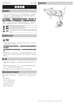
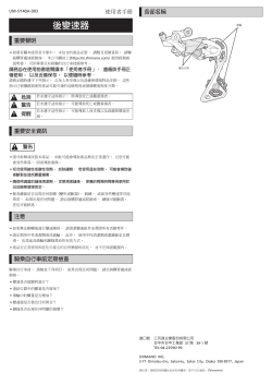
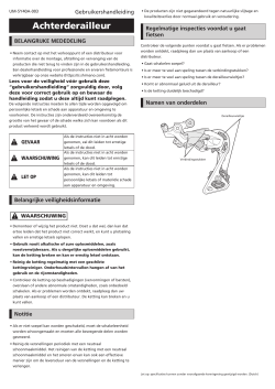
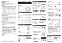
Rear Derailleur
IMPORTANT NOTICE
•
Contact the place of purchase or a distributor for information on
installation, adjustment, and replacement of the products which are
not found in the user’s manual. A dealer’s manual for professional
and experienced bicycle mechanics is available on our website (https://
si.shimano.com).
For safety, be sure to read this user’s manual
thoroughly before use, follow it for correct use,
and store it so that it can be referenced at any time.
The following instructions must be observed at all times in order to
prevent personal injury and physical damage to equipment and
surroundings. The instructions are classified according to the degree of
danger or damage which may occur if the product is used incorrectly.
DANGER
Failure to follow the instructions will result
in death or serious injury.
WARNING
Failure to follow the instructions could
result in death or serious injury.
CAUTION
Failure to follow the instructions could
cause personal injury or physical damage
to equipment and surroundings.
Important safety information
WARNING
•
Do not disassemble or modify the product. This may cause the product
to not operate correctly, and you may suddenly fall and be seriously
injured.
•
Never use alkali- or acid-based solvents such as rust cleaners. If
those solvents are used the chain might break and cause
serious injury.
•
Clean the chain with an appropriate chain cleaner regularly.
Intervals between maintenance depend on the use and riding
circumstances.
•
Check the chain for any damage (deformation or cracking), skipping,
or other abnormalities such as unintended gear shifting. If any
problems are found, consult your place of purchase or a distributor.
The chain may break, and you may fall.
Notice
•
If gear shifting operations do not feel smooth, wash the shifting unit
and lubricate all moving parts.
•
The sprockets should be periodically washed with a neutral detergent.
In addition, cleaning the chain with neutral detergent and lubricating
it can be an effective way of extending the life of the sprocket and
the chain.
•
Products are not guaranteed against natural wear and deterioration
from normal use and aging.
•
For maximum performance we highly recommend SHIMANO
lubricants and maintenance products.
Regular inspections before riding the bicycle
Before riding the bicycle, check the following items. If any problems are
found, consult your place of purchase or a distributor.
•
Is gear shifting carried out smoothly?
•
Has excess play increased in the links?
•
Has excess play increased in the pulleys?
•
Are there any abnormal noises coming from the derailleur?
•
Is there any noticeable damage on the chain?
Names of parts
Link
Pulley
UM-5Y40A-004
User’s Manual
Please note: specifications are subject to change for improvement without notice. (English)
© Feb. 2022 by SHIMANO INC. ITP
One Holland, Irvine, California 92618, U.S.A. Phone: +1-949-951-5003
High Tech Campus 92, 5656 AG Eindhoven, The Netherlands Phone: +31-402-612222
3-77 Oimatsu-cho, Sakai-ku, Sakai City, Osaka 590-8577, Japan
- About
- Blog
- Projects
- Help
-
Donate
Donate icon
An illustration of a heart shape - Contact
- Jobs
- Volunteer
- People
Bookreader Item Preview
texts
Shimano Altus SL-M310 Front Shifter 3sp User Manual
- Addeddate
- 2021-03-25 09:18:32
- Identifier
- manualzilla-id-5940765
- Identifier-ark
- ark:/13960/t3524t57x
- Ocr
- tesseract 5.0.0-alpha-20201231-10-g1236
- Ocr_autonomous
- true
- Ocr_detected_lang
- en
- Ocr_detected_lang_conf
- 1.0000
- Ocr_detected_script
- Latin
- Ocr_detected_script_conf
- 1.0000
- Ocr_module_version
- 0.0.13
- Ocr_parameters
- -l eng+Latin
- Ppi
- 300
comment
Reviews
There are no reviews yet. Be the first one to
write a review.
372
Views
DOWNLOAD OPTIONS
Uploaded by
chris85
on
SIMILAR ITEMS (based on metadata)
Групсет Shimano Altus M310 предназначен для 7- и 8-скоростной трансмиссии велосипедов для езды по городу и не очень суровому бездорожью.
![]()
Серия относится к начальному уровню, поэтому стоит недорого. Несмотря на это, все компоненты не утратили фирменного качества Шимано, что подтверждается многочисленными отзывами.
5%скидка
Для читателей нашего блога
скидка 5% на весь
ассортимент
Ваш промокод:BLOGСмотреть все товары
Общая информация
Строго говоря, если смотреть на название компонентов, то непосредственно к групсету M310 принадлежит лишь задний переключатель RD-M310.
Другие компоненты имеют отличающийся артикул, но по задумке производителя они идеально вписываются в данную серию трансмиссии и при сборке велосипеда могут покупаться вместе.
![]()
В иерархии групсетов Altus M310 занимает место между Tourney и Acera. Групсет предназначен для MTB (горных), гибридных и городских велосипедов. Не стоит с ним пытаться покорять суровые подъемы по бездорожью, но для обычных прогулок или езды на работу и домой он подходит замечательно.

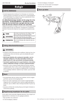
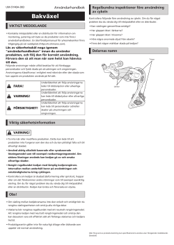
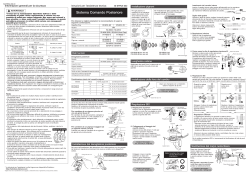
Задний переключатель
Задний переключатель RD-M310 в доступен в черном и серебристом цветах. Он рассчитан на 7–8 скоростей с общей мощностью 43Т и диапазоном звездочек 11–34Т.
![]()
Первое, что отмечается многими — простота установки. Переключатель не требует долгих и скрупулезных настроек, ведь все тросики и прочие детали хорошо отрегулированы уже с завода, и нужно лишь немного их изменить. Да и при использовании часто производить настройку не нужно, как это бывает у дешевых моделей с низким качеством.
![]()
Корпус выполнен из металла, поэтому не очень восприимчив к ударам. Люди пишут, что после аварий и падения именно на переключатель на нем оставались лишь поверхностные следы удара.
![]()
Есть и некоторые нюансы: из-за небольшой жесткости возвратной пружины лапка довольно легко подпрыгивает при движении по камням или в конце небольшого прыжка, но цепь при этом слетает крайне редко.
Поэтому не рекомендуется использовать задний переключатель RD-M310 при агрессивной езде по бездорожью — он все-таки предназначен для городской среды. Обратите внимание, что это не будет проблемой для городских или гибридных велосипедов и езды по относительно ровной поверхности.
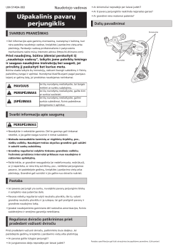
![]()
В RD-M310 ведущий шкив (G-шкив) имеет 13 зубьев, а натяжной шкив (T-образный шкив) — 15 зубьев. Это дает ему более высокую, чем в среднем, емкость цепного витка, составляющую 43 зубца. Следовательно, шкивы могут вращаться с уменьшенным трением, что приводит к снижению шума и износа.
![]()
Помимо этого, есть еще одно интересное свойство, которое возникает из-за больших шкивов. Разница незначительна, но есть небольшой прирост скорости. Например, крутя педали на четвертой передаче, вы можете получить прежний каденс на третьей передаче.
![]()
Технология Double Servo оптимизирует перемещение переключателя по звездам, удерживая его на идеальном расстоянии от каждой звездочки. Это способствует плавным и точным переключениям, которые даже ощущаются как переключения более дорогого класса.
Шифтеры и тормозные рукоятки
Модели шифтеров SL-M315 бывают для 7 и 8 задних скоростей и для 2 и 3 передних. Они совместимы с внутренней прокладкой тросиков для обеспечения большего минимализма внешнего вида велосипеда. Крепятся при помощи хомута.
![]()
Каждый шифтер имеет оптический дисплей, показывающий скорость, выбранную в данный момент. Технология Rapidfire Plus дает возможность быстро переключать несколько передач одним нажатием.
![]()
Более прогрессивное решение — объединение шифтера и тормозного рычага в моделях ST-EF505. Они подходят для гидравлических дисковых тормозов.
![]()
Если же нужна отдельная рукоятка тормоза, то подойдут модели BL-MT201 и BL-MT200. Они трехпальцевые и имеют регулировку вылета, что полезно для людей с маленькими руками.
![]()
Кассеты
Групсет Altus M310 оборудуется кассетами CS-HG200, CS-HG41-7 или CS-HG31-8. Первая модель имеет версии с 7 и 8 скоростями и различными комбинациями звездочек.
![]()
Кассета CS-HG200 выделяется вороненым покрытием, которое придает ей большую коррозионную стойкость. При этом все звездочки всех моделей сделаны из стали с перфорацией, поэтому детали не очень тяжелые, но достаточно износостойкие.
Технология Hyperglide изменяет форму профиля зубьев кассеты, что приводит к увеличению плавности и отзывчивости переключения скоростей.
Шатуны
Шатуны именно групсета Altus M310 бывают только с двумя скоростями (модель FC-M315) и комбинацией звездочек 36–22Т. Его линия цепи составляет 51,8 мм. Доступны варианты размеров 170 и 175 мм.
![]()
Если же вам нужны 3 передних скорости, то подойдут шатуны FC-TX801 (хотя они относятся к линейке Tourney).
Передние переключатели
Передний переключатель FD-M315-TS рассчитан на 2 скорости.
![]()
Он крепится к велосипеду хомутом и имеет особую форму направляющей цепи, поэтому зазор между колесами и переключателем возрастает. Это увеличивает жесткость конструкции и положительно влияет на скорость и простоту переключений.
![]()
Для варианта с шатуном на 3 скорости можно задействовать модели FD-TY600, 601 и 606 из групсета Tourney (это предусмотрено Шимано).
Цепь
Для Shimano Altus M310 подойдут цепи CN-HG71 и CN-HG40.
Главный принцип при выборе цепи — соответствие количеству скоростей и присутствие технологии HG.
5%скидка
Для читателей нашего блога
скидка 5% на весь
ассортимент
Ваш промокод:BLOGСмотреть все товары
Тормоза
Своих тормозов у групсета нет, но можно использовать дисковый гидравлический калипер BR-MT200 с двумя поршнями или гидравлический суппорт BR-UR300.
![]()
То же касается и роторов — подойдут варианты SM-RT56/30/26/10.
![]()
Втулки
Передние и задние втулки устанавливаются в зависимости от типа выбранных тормозов и роторов, поэтому их разнообразие велико. Подходят модели MT200, QC400 и 300, TC500 (добавление впереди HB обозначает переднюю втулку, а FH — заднюю).
Заключение
Запчасти Shimano Altus M310 недорого стоят, но отлично показывают себя на городских улицах и легкой пересеченной местности. В отзывах пользователи отмечают простоту установки и настроек, которые не сбиваются после продолжительной езды.