- Manuals
- Brands
- Shindaiwa Manuals
- Trimmer
- C350
Manuals and User Guides for Shindaiwa C350. We have 4 Shindaiwa C350 manuals available for free PDF download: Owner’s/Operator’s Manual, Owner’s Manual

Shindaiwa C350 Owner’s/Operator’s Manual (48 pages)
EPA Version
Brand: Shindaiwa
|
Category: Trimmer
|
Size: 2.79 MB
Table of Contents
-
Table of Contents
2
-
Attention Statements
2
-
General Safety Instructions
3
-
Checking Unit Condition
3
-
Safety Labels
5
-
Unit Description
6
-
Specifications
6
-
Assembly
7
-
Mixing Fuel
12
-
Starting the Engine
13
-
Stopping the Engine
14
-
Idle Speed Adjustment
14
-
Shoulder Strap and Harness
15
-
Cutting Grass (Trimmer Head)
15
-
Using a Brushcutter Blade
16
-
Maintenance
17
-
Daily Maintenance
18
-
Long Term Storage
19
-
Blade Sharpening
19
-
Troubleshooting Guide
20
-
Emission System Warranty
22
Advertisement

Shindaiwa C350 Owner’s Manual (28 pages)
Trimmer Head
Brand: Shindaiwa
|
Category: Trimmer
|
Size: 3.56 MB
Table of Contents
-
Table of Contents
2
-
General Trimmer Head Information
3
-
Low Profile Manual Head
4
-
Semimatic Trimmer Head
6
-
E-Z Load and E-Z Pro Trimmer Heads
8
-
High Capacity Trimmer Head
10
-
Midget Manual and High Profile Trimmer Heads
12
-
Pro-Matic and Bump ‘N’ Cut Trimmer Heads
14
-
Homepro Semi-Auto Feed
16
-
Pro Semi-Matic
18
-
Un-10
20
-
Un-30
21
-
Un-32
22
-
Flail Trimmer Head
23
-
Super Flail Trimmer Head
24
-
Fixed Line Trimmer Head
25
-
Heavy-Duty Fixed Line Head
26
-
Adaptors
27
Shindaiwa C350 Owner’s/Operator’s Manual (24 pages)
Shindaiwa Grass Trimmer Brush Cutter Owner’s Operators Manual
Brand: Shindaiwa
|
Category: Trimmer
|
Size: 2.77 MB
Table of Contents
-
Table of Contents
2
-
Attention Statements
2
-
General Safety Instructions
3
-
Safety Labels
5
-
Checking Unit Condition
5
-
Unit Description
6
-
Specifications
6
-
Assembly Procedure
7
-
Throttle Cable Adjustment
9
-
Installing a Blade
11
-
-
Mixing Fuel
12
-
Starting the Engine
13
-
Stopping the Engine
14
-
Adjusting Engine Idle
14
-
Shoulder Strap/Harness
14
-
Operation
15
-
Using a Brushcutter with a Trimmer Head
16
-
Maintenance
16
-
Long Term Storage
18
-
Blade Sharpening
18
-
Troubleshooting Guide
19
Advertisement

Shindaiwa C350 Owner’s Manual (22 pages)
Grass Trimmer/Brushcutter 350 series
Brand: Shindaiwa
|
Category: Trimmer
|
Size: 7.2 MB
Table of Contents
-
Table of Contents
2
-
Attention Statements
2
-
General Safety Instructions
3
-
Checking Unit Condition
3
-
Safety Labels
5
-
Unit Description
6
-
Specifi Cations
6
-
Assembly
7
-
Mixing Fuel
12
-
Starting the Engine
13
-
Stopping the Engine
14
-
Idle Speed Adjustment
14
-
Shoulder Strap and Harness
15
-
Cutting Grass (Trimmer Head)
15
-
Using a Brushcutter Blade
16
-
Maintenance
17
-
Daily Maintenance
18
-
Spark Arrester
19
-
Long Term Storage
19
-
Blade Sharpening
19
-
Troubleshooting Guide
20
Advertisement
Related Products
-
Shindaiwa C-35
-
Shindaiwa C350/EC1
-
Shindaiwa C335TS
-
Shindaiwa C300
-
Shindaiwa C302
-
Shindaiwa C310S
-
Shindaiwa C302TS
-
Shindaiwa C360T
-
Shindaiwa C361T
-
Shindaiwa C303TS
Shindaiwa Categories
Trimmer
Blower
Chainsaw
Portable Generator
Brush Cutter
More Shindaiwa Manuals
SHINDAIWA OWNER’S/OPERTOR’S MANUAL
T350
C350/B450
WARNING!
Read this manual and familiarize yourself with its contents.
This machine is designed for cutting grass, weed, and bushes. Do not use this machine for other purposes.
Minimize the risk of injury to yourself and others.
Do not operate or service this machine unless you clearly understand this manual.
Keep this manual at a particular place so that you can reread it whenever you have a question about its use.
Part Number 62102-94310 Rev. 02/05
2
Introduction
Shindaiwa 350 and 450-series hand held power equipment has been designed and built to deliver superior performance and reliability without compromise to quality, comfort, safety or durability.
Shindaiwa’s high-performance engines represent the leading edge of 2-cycle engine technology, delivering exceptionally high power with remarkably low displacement and weight. As an owner/operator, you’ll soon discover for yourself why Shindaiwa is simply in a class by itself!
Attention Statements
Throughout this manual are special attention statements.
WARNING!
A statement preceded by the triangular attention symbol and the word “WARN-
ING” contains information that should be acted upon to prevent serious bodily injury.
IMPORTANT!
The information contained in this owner’s/ operator’s manual describes units available at the time of publication.
CAUTION!
A statement preceded by the word
“CAUTION” contains information that should be acted upon to prevent mechanical damage.
Shindaiwa Inc. reserves the right to make changes to products without prior notice, and without obligation to make alterations to units previously manufactured.
IMPORTANT!
A statement preceded by the word
“IMPORTANT” is one that possesses special significance.
Contents
Page
Attention Statements ……………………………. 2
General Safety Instructions ………………….. 3
Safety Labels ………………………………………… 5
Checking Unit Condition ……………………… 5
Unit Description …………………………………… 6
Specifications ……………………………………….. 6
Assembly Procedure …………………………….. 7
Mixing Fuel ……………………………………….. 12
Starting the Engine …………………………….. 13
Stopping the Engine …………………………… 14
Adjusting Engine Idle …………………………. 14
Shoulder Strap/Harness …………………….. 14
Operation ………………………………………….. 15
Using a Brush Cutter
With a Trimmer Head ……………… 16
Maintenance ………………………………………. 16
Long Term Storage …………………………….. 18
Blade Sharpening ……………………………….. 18
Troubleshooting Guide ………………………. 19
Declaration of Conformity …………………… 22
NOTE:
A statement preceded by the word “NOTE” contains information that is handy to know and may make your job easier.
IMPORTANT!
The operational procedures described in this manual are intended to help you get the most from unit as well as to protect you and others from harm. These procedures are guidelines for safe operation under most conditions, and are not intended to replace any safety rules and/or laws that may be in force in your area. If you have questions regarding your Shindaiwa power tool, or if you do not understand something in this manual, your Shindaiwa dealer will be glad to assist you. You may also contact Shindaiwa, Inc. at the address printed on the back of this manual.
Read and follow this operators manual. Failure to do so could result in serious injury.
Wear head, eye, and hearing protection during the operation of this machine.
Wear non-slip gloves, long trousers and non-skid boots during the operation of this machine.
make sure no one is within 15 meters os an operating machine.
Beware of thrown objects.
The maximum speed of the cutting attachment shaft in min
-1
.
Sound Power Level (measured in accordance with 2000/14/EC)
General Safety Instructions
Work Safely
Trimmers and brushcutters operate at very high speeds and can do serious damage or injury if they are misused or abused. Never
allow a person without training or instruction to operate this unit!
Stay Alert
You must be physically and mentally fit to operate this unit safely.
WARNING!
WARNING!
Never make unauthorized attachment installations.
Never operate power equipment of any kind if you are tired or if you are under the influence of alcohol, drugs, medication or any other substance that could affect your ability or judgement.
WARNING!
Use Good Judgment
NEVER run the engine when transporting the unit.
NEVER run the engine indoors! Make sure there is always good ventilation. Fumes from engine exhaust can cause serious injury or death.
ALWAYS use the proper cutting tool for the job.
ALWAYS stop the unit immediately if it suddenly begins to vibrate or shake.
Inspect for broken, missing or improperly installed parts or attachments.
NEVER extend trimming line beyond the length specified for your unit.
ALWAYS keep the unit as clean as practical. Keep it free of loose vegetation, mud, etc.
ALWAYS hold the unit firmly with both hands when cutting or trimming, and maintain control at all times.
ALWAYS keep the handles clean.
ALWAYS disconnect the spark plug wire before performing any maintenance work.
ALWAYS, if a saw blade should bind fast in a cut, shut off the engine immediately. Push the branch or tree to ease the bind and free the blade.
3
4
The Properly Equipped Operator
Wear hearing protection devices and a broad-brimmed hat or helmet.
Wear close-fitting clothing to protect legs and arms.
Gloves offer added protection and are strongly recommended. Do not wear clothing or jewelry that could get caught in machinery or underbrush. Secure long hair so that it is above shoulder level.
NEVER wear shorts!
Keep a proper footing and do not overreach.
Maintain your balance at all times during operation.
Wear appropriate footwear (non-skid boots or shoes): do not wear opentoed shoes or sandals.
Never work barefooted!
Always wear eye protection such as goggles or safety glasses to shield against thrown objects.
Always wear a harness when operating a unit equipped with a blade.
Always operate with both hands firmly gripping the unit.
When operating with a blade, make sure the handle is positioned to provide you with maximum protection from contacting the blade.
Always make sure the appropriate cutting attachment shield is correctly installed and in good condition.
Keep away from the rotating trimmer line or blade at all times, and never lift a moving attachment above waist-high.
Be Aware of the Working Environment
Avoid long-term operation in very hot or very cold weather.
If contact is made with a hard object, stop the engine and inspect the cutting attachment for damage.
Make sure bystanders or observers outside the
15 meter “danger zone” wear eye protection.
Be extremely careful of slippery terrain, especially during rainy weather.
Always make sure the appropriate cutting attachment shield is correctly installed.
Reduce the risk of bystanders being struck by flying debris. Make sure no one is within 15 meters
— that’s about 16 paces — of an operating attachment.
15
METERS
Beware of a coasting blade when brushcutting or edging. A coasting blade can injure while it continues to spin after the throttle trigger is released or after the engine is stopped.
Be constantly alert for objects and debris that could be thrown either from the rotating cutting attachment or bounced from a hard surface.
ALWAYS clear your work area of trash or hidden debris that could be thrown back at you or toward a bystander. When operating in rocky terrain or near electric wires or fences, use extreme caution to avoid contacting such items with the cutting attachment.
Safety Labels
T350
IMPORTANT!
Safety and Operation Information
Labels: Make sure all information labels are undamaged and readable. Immediately replace damaged or missing information labels. New labels are available from your local authorized Shindaiwa dealer.
C350/B450
Checking Unit Condition
WARNING!
A cutting attachment shield or other protective device is no guarantee of protection against ricochet. YOU MUST ALWAYS
GUARD AGAINST FLYING DEBRIS!
Use only authorized Shindaiwa parts and accessories with your
Shindaiwa trimmer or brushcutter. Do not make modifications to this unit without the written approval of Shindaiwa, Inc.
NEVER operate the unit with the cutting attachment shield or other protective devices (harness, ignition switch, blade retention clip, etc.) removed!
ALWAYS make sure the cutting attachment is properly installed and firmly tightened before operation.
NEVER use a cracked or warped cutting attachment: If a properly installed attachment vibrates, replace the attachment with a new one and re-check.
ALWAYS stop the engine immediately and check for damage if you strike a foreign object or if the unit becomes tangled. Do not operate with broken or damaged equipment.
NEVER allow the engine to run at high RPM without a load. Doing so could damage the engine.
NEVER operate a unit with worn or damaged fasteners or attachment holders.
NEVER cut with a dull blade. Doing so will increase the risk of blade thrust and may also cause equipment damage.
5
Unit Description
Using the accompanying illustrations as a guide, familiarize yourself with this unit and its various components. Understanding the product helps ensure top performance, long service life, and safer operation.
WARNING!
Do not make unauthorized modifications or alterations to any of these units or their components.
Gearcase
Gearcase
Outer Tube
Ignition
Switch
T350 TRIMMER
Grip
Spark
Plug
Air
Filter
Throttle
Trigger
Tank
Guard
Fuel
Tank
Shoulder
Harness
Cutting Attachment
Shield
Throttle
Trigger
Outer Tube
Cutting Attachment
Shield
C350/B450 BRUSHCUTTER
Ignition
Switch
Spark
Plug
Air
Filter
Tank
Guard
Fuel
Tank
Handlebar
Shoulder
Harness
Specifications
Model Name ……………………………………………………………..
Engine Model …………………………………………………………………….
Engine Type ……………………………………………………………..
Displacement …………………………………………………………..
Bore and Stroke ………………………………………………………..
Maximum Power Output …………………………………………….
Engine Speed at Idling ……………………………………………….
Maximum Engine Speed …………………………………………….
Engine Speed at Maximum Power Output ……………………..
Dry Weight
(Without cutting attachment and guard.)
………………….
Dimensions (L x H x H) mm ………………………………………..
Fuel Tank Capacity ……………………………………………………
Fuel/Oil Ratio …………………………………………………………..
Carburetor Type ……………………………………………………….
Ignition ……………………………………………………………………
Spark Plug ……………………………………………………………….
Air Cleaner Type ……………………………………………………….
Starting Method ………………………………………………………..
Stopping Method ………………………………………………………
Handle Type …………………………………………………………….
Sound Pressure Level*
(average data between at Idling and at Racing) Note 1
…..
Sound Power Level**
(average data between at Idling and at Racing) Note 1
……..
Vibration Level*** Note 1 …………………… Idling (Left/Right)
Racing (Left/Right)
Sound Pressure Level*
(average data between at Idling and at WOT) Note 2
…….
Sound Power Level**
(average data between at Idling and at WOT) Note 2
……….
Vibration Level*** Note 2 …………………… Idling (Left/Right)
WOT (Left/Right)
T350/EC1 C350/EC1 B450/EC1
S350EC1 S350EC1 S450EC1
2-cycle, vertical cylinder, air cooled
33.6 cm
3
33.6 cm
3
41.5 cm
3
36 x 33 mm 36 x 33 mm 40 x 33 mm
1.3 kW 1.3 kW 1.6 kW
2,750 min
-1
2,750 min
-1
2,750 min
-1
11,500 min
-1
11,500 min
-1
11,500 min
7,500 min
-1
7,500 min
-1
7,500 min
-1
-1
7.0 kg 7.7 kg 7.7 kg
1795x365x320 1795x565x470 1795x565x475
1000 cm
3
50:1
TK, DPV11W, Diaphragm
Fully electronic, transistor controlled
NGK BMR6A
Semi-wet
Recoil Starter
Slide Switch
Bicycle Handlebar
Loop Handle
93 dB (A) 90 dB (A) 92 dB (A)
105 dB (A) 106 dB (A) 107 dB (A)
3.0/2.3 m/s
2
5.6/6.6 m/s
2
2.6/2.1 m/s
3.6/3.1 m/s
2
2
3.4/2.2 m/s
4.7/3.5 m/s
98 dB (A) 98 dB (A) 96 dB (A)
2
2
110 dB (A) 110 dB (A) 112 dB (A)
2.3/1.3 m/s
5.3/6.8 m/s
2
2
1.6/1.6 m/s
2
1.5/1.3 m/s
2
2.8/4.2 m/s
2
3.4/3.6 m/s
2
* Sound Pressure Level: In accordance with EN ISO 11806 and ISO 7917
** Sound Power Level In accordance with EN ISO 11806 and ISO 10884
*** Vibration Level: In accordance with EN ISO 11806 and ISO 7916
Note 1: 8-tooth blade equipped.
Note 2: Trimmer head equipped.
6
Assembly Procedure
Prior to Assembly
Before assembling, make sure you have all the components required for a complete unit:
Engine assembly
Outer tube assembly
Cutting attachment shield
Cutting attachment
Handlebar
Kit containing cutting attachment shield mounting bracket and hardware, operator’s handle mounting bracket and hardware, gearcase tool holder, this manual and tool kit for routine maintenance. Tool kits vary by model and may include a hex wrench, spanner and a combination spark plug wrench/screwdriver.
Carefully inspect all components for damage.
IMPORTANT!
The terms “left”, “left-hand”, and “LH”;
“right”, “right-hand”, and “RH”; “front” and
“rear” refer to directions as viewed by the operator during normal operation.
T350
ENGINE ASSEMBLY
C350/B450
ENGINE ASSEMBLY
SHOULDER
STRAP
HARNESS
7
8
Assembling the Outer Tube
T350
(1) Loosen the 2 joint bolts fully.
JOINT BOLT
NOTE:
Make sure that the throttle cable is built into the cable guide of the throttle lever.
GROUND WIRE
JOINT
THROTTLE GRIP
(2) Slip the outer tube into the joint until the tube bottoms. The outer tube or gearcase shaft may have to be rotated slightly for the splines on the mainshaft to fully engage to the engine.
(8) Shift the throttle lever back to original position, pulling the ground wire and throttle cable and tighten the screw securely.
(9) Remove the bolt tightening the cylinder cover.
(10) Put the bolt through the hole of the ground wire terminal and tighten the bolt.
Assembly of the Outer Tube
C350/B450
(1) Loosen the 2 joint bolts fully and slip the outer tube into the joint until the tube bottoms (up to the insert label).
The outer tube or gearcase shaft may have to be rotated slightly for the splines on the mainshaft to fully engage the engine.
(2) Attach the ground wire to the joint bolt.
(3) Tighten the 2 joint bolts securely.
JOINT BOLT
(4) Loosen the stopper bolt of the throttle grip. Remove the stopper bolt and nut.
(5) Fully loosen the clamp bolt of the throttle grip.
(6) Slip the right-side handlebar into the throttle grip. Locate the throttle grip so that the stopper bolt can pass through the stopper hole.
Securely tighten the stopper bolt and nut.
(7) Securely tighten the clamp bolt.
GROUND WIRE
(3) Attach the ground wire to the joint bolt.
(4) Tighten the 2 joint bolts securely.
(5) Loosen the screw which tightens the throttle lever to the outer tube. Shift the throttle lever toward the blade.
(6) Put the throttle cable into the tube.
Push throttle cable through hole in rear grip.
(7) Set the throttle cable onto the throttle lever. Use the wrench so that the wire edge goes into the slot of the throttle lever securely.
INSERT LABEL
GROUND WIRE
Assembly of the Handle
T350
WARNING!
NEVER operate this machine without the front handle. Operating without the front handle may result in serious injury.
NOTE:
Tighten four bolts diagonally to properly secure the handle.
Assembly of the Handle
C350/B450
(1) Loosen the two bolts of the lower cap and remove the lower cap.
(2) Position the handle bracket against the handle label located on the outer tube.
(3) Attach the lower cap with the two bolts and tighten the bolts. Make sure the front handle is in position per the illustration.
NOTE:
Adjust the handle at the best position for operator comfort.
(4) Secure the cable to the outer pipe with the two bands as the illustration shows. The two bands are in the tool bag.
Throttle Cable Adjustment
(1) Pull the throttle trigger gently,
and check for free-play of
approximately 5mm.
(2) If free-play is out of specifications:
(a) Slide the cable cap toward the
muffler side until the adjusting
nut and the lock nut appear.
(b) Loosen the lock nut slightly.
(c) Turn the adjusting nut so that
free-play is about 5mm.
(d) Then, tighten the lock nut.
(1) Put four square nuts in the recesses on the underside of the barrier.
(e) Slide the cable cap back.
(2) Fit the handle and barrier over the outer tube and tighten four bolts in a crisscross fashion.
HANDLEBAR
THROTTLE GRIP
OUTER TUBE
HANDLE BRACKET
HANDLE LABEL
BOLT
LOWER CAP
BAND
THROTTLE CABLE
CABLE CAP
ADJUSTING NUT
LOCK NUT
9
Cutting Attachment Shield Assembly
WARNING!
shield. Operating without the cutting attachment shield may result in serious injury.
NEVER operate this machine without the cutting attachment
(A) Cutting Attachment Shield
(B) Shield Extension (when trimmer head is in use)
(1) Attach the shield extension to the cutting attachment shield.
NOTE:
Make sure the shield extension is completely hooked at the hook receiver.
(1) Insert the cutting attachment shield between the outer tube and the lower clamp. Loosen the nut and bolt which are tightening the lower clamp if the cutting attachment shield does not fit with the lower clamp.
CAUTION!
The line cutter is attached to the shield extension and must be used when operating with a trimmer head.
NOTE:
It may be necessary to loosen the lower clamp bolt so that the shield will fit between the tube and clamp.
(2) Fit the two spacers (T350 only) and the upper clamp over the outer pipe and tighten with four bolts.
NOTE:
Tighten four bolts a crisscross fashion.
(3) Tighten the lower clamp bolt and nut securely.
WARNING!
Carefully inspect the cutting attachment shield assembly to make sure it is tightened securely and does not wobble.
10
Installing a Blade
(1) Make sure the switch is off and the engine is stopped.
(2) Wear gloves to protect your hands.
(3) Turn the unit over so the saw holder flange extending from the gear case is facing up.
(4) Using the small end of the plug wrench, loosen the bolt (turn clockwise) and remove the bolt, bolt guard, and holder B.
(5) Slide the safety clip as shown in the illustration.
(7) Put holder B and bolt guard back and at this time only finger tighten the bolt.
Make sure holder B is flat against the blade and the recess in holder B must face the blade and completely cover the safety clip.
(8) Rotate holder A until the hole in its skirt aligns with the hole in the gear case. Insert the hex wrench through both holes (to prevent the shaft from turning).
(9) Holding the hex wrench and blade with one hand, tighten the bolt (turn counterclockwise) securely using the hex socket end of the plug wrench.
(10) Remove the hex wrench.
SHAFT BOLT
BOLT GUARD
HOLDER B
WARNING!
Before operating, make sure the blade is securely mounted.
Turn the blade with your hand slightly and make sure the blade turns smoothly without wobbling.
SAFETY CLIPS
GEAR SHAFT
HOLDER A
WARNING!
The blade must fit flat. Make sure the direction of the arrow indicated on the blade corresponds with the arrow indicated on the cutting attachment shield.
WARNING!
Never operate this machine without the safety clip in place.
(6) Fit the blade over the safety clip onto holder A. Then, slide the safety clip back to its original position.
WARNING!
The blade must fit flat against holder A. The blade’s mounting hole must be centered over the raised boss of holder A.
11
Mixing Fuel
WARNING!
Minimize the risk of fire, burns, and personal injury!
STOP engine before refueling.
ALWAYS allow the engine to cool before refueling
ALWAYS open the fuel cap slowly to allow any pressure build-up in the tank to release fuel vapor slowly.
ALWAYS transport and store fuels in an approved container.
Avoid overfilling and wipe-up all spilled fuel. Move the engine at least 3 meters from the fueling point, storage area, and other readily flammable materials before restarting.
ALWAYS inspect the unit for fuel leaks before each use. During each refill, make sure there are no fuel leaks around the fuel cap and/ or tank. If a fuel leak is evident, stop using the unit immediately.
Fuel leaks must be repaired before using the unit.
NEVER smoke or light any fires near the engine or fuel source.
NEVER place any flammable material near the engine or muffler.
NEVER operate the engine without the muffler in good working condition.
ALWAYS move the unit to a place well away from a fuel storage area or other readily flammable materials before starting the engine.
CAUTION!
This engine is designed to operate on a 50:1 mixture consisting of unleaded gasoline and a premium 2-cycle mixing oil only. Use of Non-approved mixing oils can lead to excessive maintenance costs and/or engine damage.
CAUTION!
Some gasolines contain alcohol as an oxygenate! Oxygenated fuels may cause increased operating temperatures. Under certain conditions, alcohol-based fuels may also reduce the lubricating qualities of some mixing oils. Never use any fuel containing more than 10% alcohol by volume!
Generic oils and some outboard motor oils may not be intended for use in high-performance air cooled 2-cycle engines, and should never be used in your Shindaiwa engine!
Filling The Fuel Tank
IMPORTANT!
Mix only enough fuel for your immediate needs! If fuel must be stored longer than
30-days, it should first be treated with a stabilizer such as StaBil™ or equivalent product!
Use only fresh, clean unleaded gasoline with a pump octane rating of 87 or higher.
Mixing fuel with a Premium 2-cycle mixing oil designed for use with highperformance 2-cycle air-cooled engines.
Refer to the following examples of 50:1 fuel to oil mix quantaties:
Gasoline 2-cycle mixing oil liters milliliters
2.5 l ……………………….. 50 ml
5 l …………………………..100 ml
10 l …………………………200 ml
20 l …………………………400 ml
CAUTION!
Never attempt to mix fuel in the unit’s fuel tank. Always mix all fuels in a clean approved container.
1. Place the unit on a flat, level surface, and wipe any debris from around the fuel cap.
2. Remove the fuel cap.
3. Fill the tank with clean, fresh fuel.
4. Replace the cap, and wipe away any spilled fuel before starting the engine.
12
Starting the Engine
WARNING!
MAKE SURE THE BLADE
IS WELL CLEAR OF ANY
INTERFERENCE. Before starting the engine, place unit on clear, level surface. Make sure you have good secure footing and always keep a firm grip on the machine. THE CUTTING
ATTACHMENT MAY ROTATE WHEN
THE ENGINE STARTS.
WARNING!
Move at least three meters away from the fuel site before starting the engine.
WARNING!
Never operate the engine without the cutting attachment installed.
Starting a Cold Engine and/or
Restarting After Refueling.
T350
C350/B450
(b) Prime the engine by repeatedly depressing the carburetor primer bulb until fuel can be seen flowing through the transparent overflow return tube:
IMPORTANT!
Repeated cranking of the engine with the choke CLOSED (“ “) will lead to engine flooding. If the engine fails to start after several attempts, move the choke lever to the OPEN position and continue cranking.
(c) Push the choke lever upward
(“ closed“ position). (Cold engine.)
(f) When the engine first fires, gradually return the choke to OPEN
(“ ”) position if you have not already done so.
• If the engine stops before the choke is fully open, restart with the choke closed.
• If the engine stops after the initial firing, restart with choke closed.
(g) When the engine starts and is running, set the engine to idle by tapping the throttle lever to release the throttle lock.
Make sure the cutting attachment is clear of obstructions.
WARNING!
Never start the engine from the operating position.
Starting a Warm Engine
Starting a warm engine involves all of the steps of starting a cold engine.
EXCEPT:
• The choke should be in the OPEN position.
If the engine does not start, follow the cold engine starting procedure.
(d) Depressing the lock lever, pull the throttle lever fully and depress the throttle lock button. While depressing the throttle lock button, release the throttle lever and the lock lever. Now the throttle stays at high idle (starting speed).
(e) While firmly holding the outer tube with one hand, pull the recoil starter handle upward with your other hand.
Pull slowly at first until you feel the starter engage, then pull quickly to start the engine. Do not pull the starter rope to the end of its travel.
When the engine starts:
• After the engine starts, disengage the throttle lock and allow the engine to warm-up at idle for 2 or 3 minutes before operating the machine.
• After the engine is warm, pick up the machine and clip-on the strap.
• Advancing the throttle makes the cutting attachment rotate faster; releasing the throttle makes the attachment stop running. If the cutting attachment continues to rotate, carburetor idle speed should be adjusted.
(See next page.)
CAUTION!
Pulling the starter rope to the end of its travel may damage the starter mechanism.
(a) Slide the ON-OFF switch to the “I” position.
13
Stopping the Engine
Idle the engine briefly before stopping, then slide the ON-OFF switch to the “O” (for STOP) position.
WARNING!
The cutting attachment continues rotating for a while after the switch is turned off.
(3) If a tachometer is available, the engine idle speed should be adjusted to 2,750 min
-1
(rpm)
NOTE:
Carburetor fuel mixture adjustments are preset at the factory on units with emission control systems and cannot be serviced in the field.
Emergency Release
In case of emergency, firmly pull the white tab at the hook. The machine will release from the strap.
C350/B450 T350
C350/B450
T350
Engine Idle Adjustment
The engine must return to idle speed whenever the throttle lever is released. Idle speed is adjustable, and must be set low enough to permit the engine clutch to disengage the cutting attachment when the throttle is released.
Shoulder Strap/Harness
To Wear the Strap
(1) Attach the strap hook to the hanger on the outer pipe.
(2) Wear the strap so that the hook stays at your right side.
(3) Adjust the length of the strap so that you can hold and operate the machine comfortably.
(4) Make sure the hip pad stays between your hip and outer pipe. (B450
ONLY)
IMPORTANT!
Adjust the shoulder strap so the shoulder pad rests comfortably on the off-side shoulder and the cutting path of the cutting attachements is parallel to the ground. Make sure all hooks and adjustment devices are secure.
WARNING!
Always wear a harness when operating this unit with a blade.
C350
B450
WARNING!
The cutting attachment must
NEVER rotate at engine idle!
If the idle speed can not be adjusted by the procedure described here, have the unit inspected at an authorized
Shindaiwa dealer.
T350
NOTE:
Using a harness with a bruscutter allows you to maintain proper control of the unit and reduces fatigue during extended operation.
Double Shoulder Harness
Adjust the double shoulder harness straps so the shoulder pads rest comfortably on the offside of the shoulder and the cutting path of the blade is parallel to the ground.
Make sure all hooks and adjusting devices are secure.
Idle Adjust
Screw
(1) Place the unit on the ground, then start the engine and allow it to idle for 2-3 minutes until warm.
(2) If the attachment rotates when the engine is at idle, reduce the idle speed by turning the idle adjustment screw counterclockwise.
14
Operation
Using A Blade
(1) After starting the engine, pull
the throttle lever gradually.
The engine speed increases
and the blade will start
rotating.
(2) When the throttle lever is
released, the engine goes
back to idle speed
automatically.
(3) Operate the machine at full
throttle while cutting. Best
fuel efficiency is obtained by
releasing the throttle when
swinging back after cut.
(4) The blade rotates
counterclockwise. For best
performance and to minimize
being stuck by debris, move
the blade from right to left
while advancing on your
work.
WARNING!
Position the blade so cuts are made between blade’s
8 o’clock and 10 o’clock positions (as viewed from above).
DO NOT cut between the 11 o’clock and 5 o’clock positions.
WARNING!
“BLADE THRUST” is a sudden sideway or backward motion of the machine. Such motion may occur when the blade jams or catches on an object such as a sapling tree or tree stump. BE CONSTANTLY ALERT
FOR BLADE THRUST AND GUARD
AGAINST ITS EFFECTS.
CAUTION!
To prevent possible engine damage, do not allow the machine to run at high speeds without a load. Avoid operating the engine at low speeds. Doing so can lead to rapid clutch wear. In addition, slow-speed operation tends to cause grass and debris to wrap around the cutting attachment.
Recommended
Cutting Attachments
Make sure to use the following recommended Shindaiwa cutting attachment with this machine.
Blades
PART NUMBER 60903-98310
8-TOOTH BLADE
INNER BORE: 25.4mm
DIAMETER: 255.0mm
THICKNESS: 2.0mm
PART NUMBER 72430-92142
3-TOOTH BLADE
INNER BORE: 25.4mm
DIAMETER: 255.0mm
THICKNESS: 2.2mm
PART NUMBER 60903-98320
4-TOOTH BLADE
INNER BORE: 25.4mm
DIAMETER: 255.0mm
THICKNESS: 2.0mm
Trimmer Heads
(A) C350
PART NUMBER 78820-16000
TAP & FEED TRIMMER HEAD
BOLT DIAMETER: 10mm
THREAD: LEFT,1.25mm PITCH
(B) B450
PART NUMBER 78820-14000
SEMI-AUTOMATIC TRIMMER HEAD
BOLT DIAMETER: 10mm
THREAD: LEFT,1.25mm PITCH
(C) T350
PART NUMBER 78820-15000
TAP & FEED TRIMMER HEAD
BOLT DIAMETER: 8mm
THREAD: LEFT,1.25mm PITCH
CAUTION!
DO NOT use 2-tooth blades with this machine.
WARNING!
NEVER strike or slam the spinning blade against the wood.
WARNING!
When transporting, make sure the engine is not running and blade is covered with blade cover.
15
Using a Brushcutter With a Trimmer Head
You may install one of several types of Shindaiwa trimmer heads on your TC350/B450 trimmer or brushcutter, each with features for specific applications and/or operational requirements.
For proper operation, always refer to the instructions accompanying the trimmer head being used. Available trimmer head styles include:
Semi-automatic. Trimmer line is indexed when the operator taps the trimmer head on the ground during operation.
Manual. The operator indexes line manually with the grass trimmer stopped.
Fixed. The operator must stop the unit and add new lengths of trimmer line manually.
Flail. This device, designed for clearing weeds and light brush, features three nylon blades attached to the head by pivots.
Engine Operating Speeds
Operate at full throttle while cutting grass.
CAUTION!
Operation at low rpm can lead to premature clutch failure.
Trimming and Mowing Grass
Hold the grass trimmer so the trimmer head is angled slightly into the area to be cut. To ensure maximum trimmer-line service life, cut only with the tip of the trimmer line. Cut grass by swinging the unit’s trimmer head from left to right. Keep the trimmer head horizontal.
RETURN
PATH
CUTTING
PATH
CAUTION!
Do not push the rotating line into trees, wire fences or any material that could tangle or break line ends.
Maintenance
WARNING!
Before performing any m a i n t e n a n c e , r e p a i r, or cleaning work on the machine, make sure the engine and cutting attachment are completely stopped. Disconnect the spark plug wire before performing service or maintenance work.
WARNING!
Never repair a damaged blade by welding, straightening, or by modifying its shape.
An altered blade may break during operation, resulting in serious personal injury.
23041
Edging
Tilt the handle about 100° to the left (from horizontal) and move forward, holding the trimmer or brushcutter vertically as shown.
Daily Maintenance
Prior to each work day, perform the following:
Remove the dirt and debris
from the engine, check the
cooling fins and air cleaner
for clogging, and clean them
as necessary.
Carefully remove any
accumulations of dirt or
debris from the muffler and
fuel tank. Dirt buildup in
these areas can lead to
engine overheating, fire, or
premature wear.
Check for loose or missing
screws or components. Make
sure the cutting attachment
is securely fastened.
Check the machine for
leaking fuel or grease.
23042
16
10 Hour Maintenance
Remove the air cleaner element from the carburetor and clean it thoroughly with soap and water. Squeeze out excess, let dry and reassemble the element.
CAUTION!
Do not operate the machine if the air cleaner or element is damaged, or if the element is water-soaked.
50 Hour Maintenance
Cleaning
Remove and clean the cylinder cover and clean grass and dirt from the cylinder fins.
MUFFLER
COVER
BOLT
STAY
CYLINDER
COVER
PROTECTOR
BOLT
GASKET
Muffler Maintenance
(350 only)
Hard starting or a gradual loss of performance can be caused by carbon deposits lodged in the muffler’s spark arrester screen.
In such cases, performance can usually be restored by removing the spark arrester screen and giving it a thorough cleaning with a stiff bristle brush.
If carbon deposits are severe or if no performance improvement is noted, your unit should be returned to your Shindaiwa dealer for inspection.
Muffler
Remove the cutting attachment and the gear shaft collar, and press new grease into the gear case until the old grease has been pushed out. Use only lithium base grease (such as Shindaiwa Gear Case Lubricant).
12-6 50 Hour Maintenance
10/15 Hour Maintenance
Remove and clean the spark plug.
Adjust the spark plug electrode gap to 0.6 — 0.7mm. If the plug must be replaced, use only NGK BMR6A.
CAUTION!
Before removing the spark plug, clean the area around the plug to prevent dirt and dust from getting into the engine’s internal parts.
Fuel Filter Maintenance
Use a hooked wire to extract the fuel filter from inside the fuel tank.
Remove and replace the filter element. Before reinstalling the filter, inspect the condition of the fuel line. If damage or deterioration are noted, the unit should be removed from service until you can consult with an authorized servicing dealer.
CAUTION!
Make sure you do not pierce the fuel line with the end of the hooked wire.
The line is delicate and can be damaged easily.
Spark
Arrester
WARNING!
Never operate this unit with a damaged or missing muffler or spark arrester! Operating with missing or damaged exhaust components is a fire hazard and may also damage your hearing.
Hooked
Wire
17
Long Term Storage
Whenever the unit will not be used for
30 days or longer, use the following procedures to prepare it for storage:
Clean external parts thoroughly and apply a light coating of oil to all metal surfaces.
Drain all the fuel from the fuel tank.
IMPORTANT!
All stored fuels should be stabilized with a fuel stabilizer such as STA-BIL™.
Blade Sharpening
With the file or a grinder, file a blade as follows.
WARNING!
Sharpen only the cutting teeth of a blade. DO NOT alter the contour of the blade in any way. In order to keep the blade in balance, all cutting edges must be sharpened equally. DO NOT file the tips of the teeth too sharp.
Make sure the width of the 3 sides/4 sides is all the same.
The sharpening angle should be 45
0
approx.
Do not file the tips of the blade too sharp. Leave 0.2~0.5mm unsharpened.
To remove the remaining fuel from the fuel lines and carburetor and with the fuel drained from the fuel tank.
1. Prime the primer bulb until no more fuel is passing through.
2. Start and run the engine until stops running.
3. Repeat steps 1 and 2 until the engine will no longer start.
CAUTION!
Gasoline stored in the carburetor for extended periods can cause hard starting, and could also lead to increased service and maintenance costs.
The bottom of each tooth must remain unsharpened. (Blade as viewed from bottom)
Remove the spark plug and pour about
7 grams of 2-cycle mixing oil into the cylinder through the spark plug hole.
Slowly pull the recoil starter 2 or 3 times so oil will evenly coat the interior of the engine. Reinstall the spark plug.
Before storing the unit, repair or replace any worn or damaged parts.
Remove the air cleaner element from the carburetor and clean it thoroughly with soap and water. Let dry and reassemble the element.
Store the unit in a clean, dust-free area.
4-Tooth Blade
8-Tooth Blade
18
Troubleshooting Guide
What To Check
Does the engine crank?
NO
YES
Good compression?
NO
YES
Does the tank contain fresh fuel of the proper grade?
NO
YES
Is fuel visible and moving in the return line when priming?
YES
Is there spark at the spark plug wire terminal?
NO
NO
YES
Check the spark plug.
NO
Engine Does Not Start
Possible Cause
Faulty recoil starter.
Fluid in the crankcase.
Internal damage.
Remedy
Consult with an authorized servicing dealer.
Loose spark plug.
Excess wear on cylinder, piston, rings.
Fuel incorrect, stale, or contaminated; mixture incorrect.
Tighten and re-test.
Consult with an authorized servicing dealer.
Refill with clean fresh unleaded gasoline with a pump octane of
87 or higher, mixed with
Premium 2-cycle mixing oil at a 50:1 gasoline/oil ratio.
Check for clogged fuel filter and/or vent.
Replace fuel filter or vent as required.
Restart.
The ignition switch
is in “O” (OFF) position.
Shorted ignition ground.
Faulty ignition unit.
Move switch to “I” (ON) position and re-start.
Consult with an authorized servicing dealer.
If the plug is wet, excess fuel may be in the cylinder.
Crank the engine with the plug removed, replace the plug, and re-start.
The plug is fouled or improperly gapped.
The plug is damaged internally or of the wrong size.
Clean and re-gap the plug to
0.6 ~ 0.7 mm. Re-start.
Replace the plug with a
NGK BMR6A. Re-start.
19
Troubleshooting Guide (Continued)
Low Power Output
What To Check
Is the engine overheating?
Possible Cause
Operator is overworking the unit.
Remedy
Cut at a slower rate.
Carburetor mixture is too lean.
Consult with an authorized servicing dealer.
Improper fuel ratio.
Refill with clean fresh unleaded gasoline with a pump octane of
87 or higher, mixed with
Premium 2-cycle mixing oil at a
50:1 gasoline/oil ratio.
Engine is rough at all speeds.
May also have black smoke and/or unburned fuel at the exhaust.
Engine is knocking.
Fan, fan cover, cylinder fins dirty or damaged.
Carbon deposits on the piston or in the muffler.
Clean, repair or replace as necessary.
Consult with an authorized servicing dealer.
Clogged air cleaner element.
Loose or damaged spark plug.
Air leakage or clogged fuel line.
Water in the fuel.
Clean or replace the air filter.
Tighten or replace the plug with a NGK BMR6A. Re-start.
Repair or replace fuel filter and/or fuel line.
Refill with fresh fuel/oil mixture.
Piston seizure.
Faulty carburetor and/ or diaphragm.
Consult with an authorized servicing dealer.
Consult with an authorized servicing dealer.
Overheating condition.
Improper fuel.
Carbon deposits in the combustion chamber.
See above.
Check fuel octane rating; check for presence of alcohol in the fuel. Refuel as necessary.
Consult with an authorized servicing dealer.
20
Troubleshooting Guide (Continued)
Additional Problems
Symptom
Poor acceleration.
Possible Cause
Clogged air filter.
Clogged fuel filter.
Remedy
Clean or replace the air filter.
Replace the fuel filter.
Lean fuel/air mixture.
Engine stops abruptly.
Idle speed set too low.
Switch turned off.
Fuel tank empty.
Clogged fuel filter.
Water in the fuel.
Consult with an authorized servicing dealer.
Adjust: 2,750 min
-1
Reset the switch and re-start.
Refuel. See page 12.
Replace fuel filter.
Shorted spark plug or loose terminal.
Ignition failure.
Piston seizure.
Drain; replace with clean fuel.
See page 12.
Clean or replace spark plug with a NGK BMR6A. Tighten the terminal.
Replace the ignition unit.
Consult with an authorized servicing dealer.
Engine difficult to shut off.
Ground (stop) wire is disconnected, or switch is defective.
Overheating due to incorrect spark plug.
Overheated engine.
Test and replace as required.
Replace spark plug with a NGK BMR6A.
Idle engine until cool.
Cutting attachment moves at engine idle.
Engine idle too high.
Broken clutch spring or worn clutch spring boss.
Loose attachment holder.
Set idle: 2,750 min
-1
Replace spring/shoes as required, check idle speed.
Inspect and re-tighten holders securely.
Excessive vibration
Attachment will not rotate
Warped or damaged attachment.
Loose gearcase.
Bent main shaft/worn or damaged bushings.
Shaft not installed in powerhead or gearcase.
Broken shaft.
Inspect and replace
attachment as required.
Tighten gearcase securely.
Inspect and replace
as necessary.
Inspect and reinstall
as required.
Damaged gearcase.
Consult with an authorized
servicing dealer.
Consult with an authorized
servicing dealer.
21
22
Declaration of Conformity
DECLARATION
OF
CONFORMITY
We hereby declare the Shindaiwa Engine Engine Brushcutter,
Model RM 350 (T350/EC1, C350/EC1).
meets the following respective requirements.
Council Directives: Standard taken:
89/336/EEC as amended EN 292 parts 1&2
98/37/EC as amended ISO 11806
2000/14/EC as amended
2004/26/EC as amended
CISPR 12
Measured sound power level: 113dB(A)
Guaranteed sound power level: T350/EC1:114dB(A), C350/EC1:115dB(A)
Technical documentation is kept by:
K. Maeda DIV. Manager
Engineering Research and Development DIV.
16th February, 2005
Shindaiwa Kogyo Co., Ltd.
Head office: 6-2-11, Ozuka—Nishi, Asaminami—Ku,
Hiroshima, 731—3167, Japan
TEL: 81-82-849-2003, FAX: 81-82-849-2482
T. Yoshitomi
DIV. Manager
Quality Assurance DIV.
Shindaiwa Kogyo Co., Ltd.
Head office: 6-2-11, Ozuka—Nishi, Asaminami—Ku,
Hiroshima, 731—3167, Japan
TEL: 81-82-849-2206, FAX: 81-82-849-2481
Declaration of Conformity
DECLARATION
OF
CONFORMITY
We hereby declare the Shindaiwa Engine Engine Brushcutter,
Model RM 450 (T450/EC1, B450/EC1).
meets the following respective requirements.
Council Directives: Standard taken:
89/336/EEC as amended EN 292 parts 1&2
98/37/EC as amended ISO 11806
2000/14/EC as amended
2004/26/EC as amended
CISPR 12
Measured sound power level: 115dB(A)
Guaranteed sound power level: 117dB(A)
Technical documentation is kept by:
K. Maeda DIV. Manager
Engineering Research and Development DIV.
16th February, 2005
Shindaiwa Kogyo Co., Ltd.
Head office: 6-2-11, Ozuka—Nishi, Asaminami—Ku,
Hiroshima, 731—3167, Japan
TEL: 81-82-849-2003, FAX: 81-82-849-2482
T. Yoshitomi
DIV. Manager
Quality Assurance DIV.
Shindaiwa Kogyo Co., Ltd.
Head office: 6-2-11, Ozuka—Nishi, Asaminami—Ku,
Hiroshima, 731—3167, Japan
TEL: 81-82-849-2206, FAX: 81-82-849-2481
23
Shindaiwa Inc.
11975 SW Herman Rd.
Tualatin, Oregon 97062
U.S.A.
Telephone: 503 692-3070
Fax: 503 692-6696 www.shindaiwa.com
Shindaiwa Kogyo Co., Ltd.
6-2-11, Ozuka-Nishi,
Asaminami-Ku, Hiroshima
731-3167, Japan
Telephone: 81-82-849-2220
Fax: 81-82-849-2481
© 2005 Shindaiwa Inc.
Part Number 62102-94310
Revision 02/05
Shindaiwa is a registered trademark of Shindaiwa, Inc.
Specifications subject to change without notice.

- Обзор
- Отзывы
Обзор
Бензиновый триммер SHINDAIWA C 300 оснащен мощным двухтактным двигателем.Два поршневых кольца Хромированная поверхность цилиндра увеличивает надежность и срок службы триммера SHINDAIWA. Карбюратор, работающий в любом положении.Бензиновый триммер SHINDAIWA C 230 S с большим топливным баком позволяет работать длительное время без дозаправки.Полная антивибрационная защита.Кованный вал из углеродистой стали.Микропроцессорная система зажигания облегчает пуск двигателя бензокосы SHINDAIWA C 350 Защитный экран глушителя для лучшего охлаждения цилиндра.Лёгкий доступ к воздушному фильтру упрощает обслуживание Бензиновый триммер SHINDAIWA C 350 может резать как триммерной головкой с леской (Опция, головка SHINDAIWA Speed-Feed заказывается отдельно), так и металлическим ножом (входит в комплект) Сцепление автоматическое (центробежная муфта).Искрогаситель в глушителе Комплектация:Триммерная головка,косильный нож,кожух ножа,монтажный ключ.
Мощность двигателя 1,3 Квт
Бензин не ниже Аи-92
Двигатель бензиновый, 1-цилиндровый, 2-тактный.
Топливный бак 0,6 л.
Рабочий объем 33,6 куб.см.
Максимальная диаметр ножа 230 мм
Штанга Прямая
Вес 7,6 кг
-

- Регистрация:
- 03.07.10
- Сообщения:
-
1.225
- Благодарности:
- 473
Лодочник
гонимый
- Регистрация:
- 03.07.10
- Сообщения:
- 1.225
- Благодарности:
- 473
- Адрес:
- Москва
Shindaiwa c350 отзыв дачникаЧто-то про неё темы нет, а коса достойная…
Купил в прошлом году.
Косил 2 сезона 20 соток (чистых, без грядок).Комплектация косы, супер.
Ранцевый ремень вообще песня. (Коса весит 7 кг, на ранце её практически не чувствую, знай себе вожу руками из стороны в сторону)
Мощность, даже сказал бы, избыточная (для дачника-любителя). 1.7,…1,8 что ли.
В первый год косил бурьян с ивняком, ножом, все 20 соток. — Только брызги летели")
")
В этом году, кошу леской. Та что была в комплекте, стерлась со средней скоростью.
Счас купил какую то дешевую, за 250 рэ, держится нормально.
Репьи, колючки и подорожник с одуванчиками — в дрызг!Цена (не знаю. сейчас она продается иль нет?) в прошлом году брал за 15.
Из минусов:
Стала заводится с 3-4 рывка. (Прогретая заводится с пол оборота, даже можно на себе (ежели извернуться)
Что-то редуктор сильно греется (Или кажется?) (смазан хорошо)
И еще что странно, так это упаковка…
Изделие позиционируется как чистая Япония. А коробка наша и написано по нашему же..Грубый картон и черная типографская краска…(попахивает совком)
(бензопилы кста, тоже в такие коробки упаковывают)Последнее редактирование: 12.07.16
-
- Регистрация:
- 03.07.10
- Сообщения:
-
1.225
- Благодарности:
- 473
Лодочник
гонимый
- Регистрация:
- 03.07.10
- Сообщения:
- 1.225
- Благодарности:
- 473
- Адрес:
- Москва
Не далее как вчера и позавчера (более двадцати соток за два дня кошу, чтоб не переломаться (просто трава 30-40 см + репьи и всякие колючки + тропинка через бурьян к ручью (50х1.5м.)
+ спуск к самому ручью 30м (бурелом и малинник дикий+крапива с рост)Не чихнет.
Правда высокую траву (под 80 см) леской, получается только за 2 среза (сначала по центру, и второй мах под корень)…Иначе наматывает.
Катушка Спид Фид радует, по истерлась чуть снаружи, но не критично.
Катушку не жалею, обдираю у досок и бордюров..тока лески расход больше.Попробовал чуть отодвинуть щиток от головки…Понравилось, скос шире. Лески реально выходит чуть больше.
Расход лески увеличился ну и фиг с ним..не те деньги.Пс. В самом начале, как только купил и первый раз покосил, сочилось масло из непонятного отверстия.
Мистика..
Вообще не ясно что это было.
Списывался с сервисом, там тоже голову ломали..ибо это отверстие В НИКУДА.
Призраки в машинеВот ранец. (своей фотки нет, взял с нэта)

Реально как самурайский доспех (сзади широко написано тиснением «shindaiwa»)
-

- Регистрация:
- 04.10.11
- Сообщения:
-
7.598
- Благодарности:
- 10.480
Алвен
Заблокирован
Живу здесь
- Регистрация:
- 04.10.11
- Сообщения:
- 7.598
- Благодарности:
- 10.480
- Адрес:
- Орда
Может их фасуют у нас ?

-
- Регистрация:
- 03.07.10
- Сообщения:
-
1.225
- Благодарности:
- 473
Лодочник
гонимый
- Регистрация:
- 03.07.10
- Сообщения:
- 1.225
- Благодарности:
- 473
- Адрес:
- Москва
-
- Регистрация:
- 03.07.10
- Сообщения:
-
1.225
- Благодарности:
- 473
Лодочник
гонимый
- Регистрация:
- 03.07.10
- Сообщения:
- 1.225
- Благодарности:
- 473
- Адрес:
- Москва
Газонную траву, (если она разрослась и уплотнилась) не косит нихрена.
(Касается всех триммеров, тут без вариантов, не, можно конечно муки адовы принимать и выкосить..но нафига?).
Надо брать бензосамоход.Пс. так что, если у вас триммер, любой, газон лучше косить почаще не давая ему вырасти более 20см..Тогда и триммером побрить можно)
Последнее редактирование: 31.08.16
-
- Регистрация:
- 03.07.10
- Сообщения:
-
1.225
- Благодарности:
- 473
Лодочник
гонимый
- Регистрация:
- 03.07.10
- Сообщения:
- 1.225
- Благодарности:
- 473
- Адрес:
- Москва
Ни чихнет и по сей день..И голова держится, хоть бы хны.
-
- Регистрация:
- 03.07.10
- Сообщения:
-
1.225
- Благодарности:
- 473
Лодочник
гонимый
- Регистрация:
- 03.07.10
- Сообщения:
- 1.225
- Благодарности:
- 473
- Адрес:
- Москва
Конец лета 23 его…
Счас такую НЕ купить. Работает. Не чихнёт не пёрнет. Молюсь чтобы и дальше так.
0%

Артикул: 14920
Мощность 1,8 л.с.
Рабочий объем 33,6 см 3

Официальный дилер
(нам 14 лет)

Официальная гарантия

Рейтинг 5 звезд
от Яндекс.Маркет

Быстрая доставка
(0-1 день)
Описание
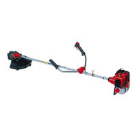
Триммер бензиновый Shindaiwa C350
Триммер Shindaiwa C350 отлично подойдет для работы на садовом участке до 25 соток и в городе. Мощная, профессиональная бензокоса Shindaiwa отличается высоким качеством, выносливостью и долговечностью, также обладает особенностями, позволяющие аппарату сократить вредные выбросы в атмосферу, соответствуя европейским требованиям. Агрегат может работать не только с леской, на него также можно установить насадку — нож. Даже после длительного простоя или в прохладную погоду мотокоса Shindaiwa C350 включается без проблем.
Технические характеристики
|
Мощность, л.с. |
1,8 |
|
Вес, кг. |
7,6 |
|
Рабочий объем, см 3 |
33,6 |
|
Диаметр лески, мм |
2,4 |
|
Штанга |
Прямая |
|
Модель двигателя |
Sure Start. |
|
Тип двигателя |
Бензиновый 2-х тактный |
|
Ширина скашивания леской/ножом, см. |
40/25 |
|
Емкость топливного бака, л. |
1,0 |
|
Топливо |
Бензин АИ-92+ масло |
|
Материал штанги |
алюминий |
|
Обороты двигателя при максимальной мощности, об/мин. |
8000 |
|
Уровень силы звука, Дб. |
106 |
|
Ремень |
плечевой |
|
Рукоятка |
D -образная в виде руля |
Особенности и преимущества
Хорошая мощность
Большой крутящий момент
Хромированная поверхность цилиндра
Легкий доступ к воздушному фильтру
Советы по обслуживанию:
- Нельзя осуществлять ремонт или регулировку привкл. двигателе, необходимо откл. высоковольтный провод от свечи зажигания.
- Необходимо чтобы болты и гайки крепящие нож былихорошо затянуты.
- Требуется содержать агрегат в чистоте,производить своевременную чистку.
- Перед началом работы проверять уровень масла.Доливать масло до метки в картере. Замена масла нужна каждые 25 часовнаработки или раз в сезон. Можно менять чаще, в особенности при работе всильной пыли.
- Агрегат должно быть хорошо смазанным, но нельзя смазыватьпластиковые подшипники колес. Для подшипников колес рекомендуетсяиспользовать только сухую смазку на основе графита и в небольшомколичестве.
- Быть уверенным в свободном ходе колес.
- Следить за остротой ножей и их естественнымсостоянием. Рекомендуется приобретать ножи для замены.
- Замену вкладыша воздушного фильтра следуетпроизводить каждые 100 часов или одни раз в сезоне. В пыльных условияхменять чаще. Бензин и керосин повреждают вкладыш возд. фильтра. Нельзясмазывать и чистить или сушить сжатым воздухом.
- Необходимо следить за ржавчиной на глушителе икорпусе.
- Замена свечи зажигания каждые 100 часов или новыйсезон.
- Очистка под кожухом производится не меньше 2 храз в сезон, например металлическим шпателем. Задний дефлекторпредохраняет оператора от предметов захваченных ножом, следите за егоцелостностью.
Информация на сайте не является публичной офертой.
Внешний вид и комплектация может быть изменена производителем без предварительного уведомления.
Триммер бензиновый Shindaiwa C350
Наличный и безналичный расчет, банковские карты
Отзывы
Хотите оставить отзыв?Поставьте свою оценку!
Сделайте выбор!