В ГРАФИЧЕСКОМ РЕДАКТОРЕ CorelDraw:
1. Создайте макет в графическом редакторе
2. Зайдите в приложения и нажмите SEND TO SIGNCUT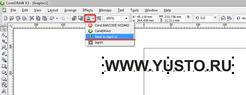
3. Откроется интерфейс программы SIGNCUT
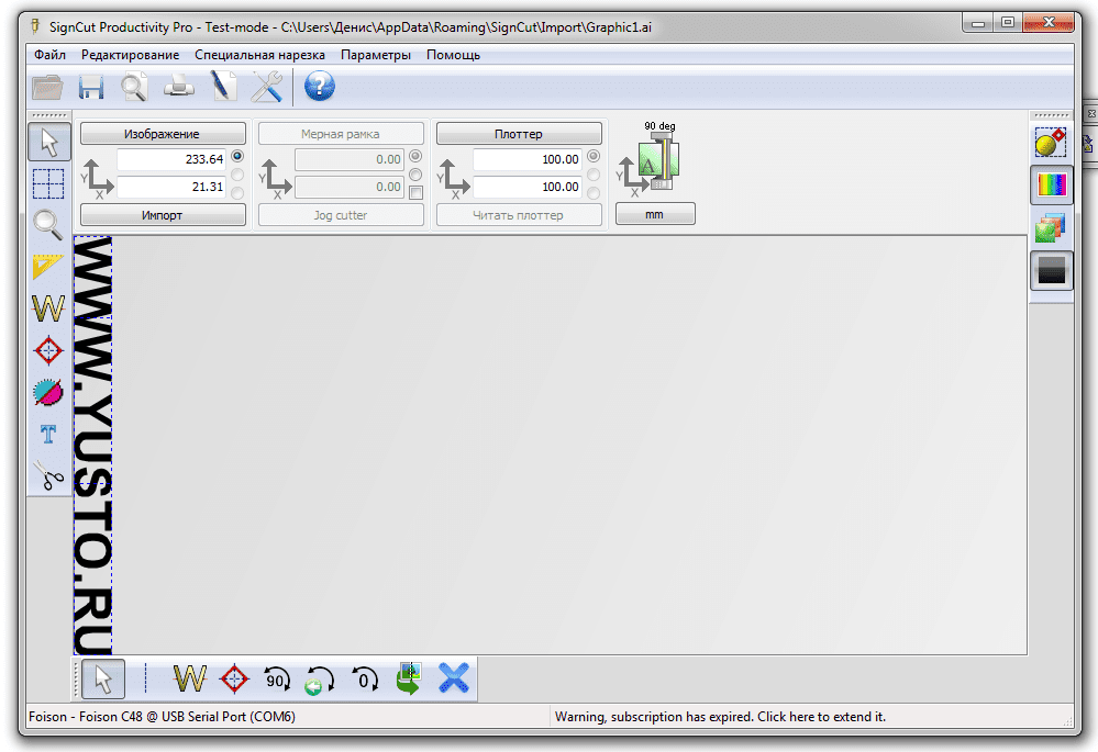
4. Выровняйте изображение по листу кнопкой 
5. Отправьте на резку макет, нажав кнопку 

Фрезерный станок ЧПУ VENO K45MT2040
Рабочее поле: 2000х4000 мм. Мощность шпинделя: 4,5 кВт. Цанговый патрон: ER-32. Высота портала:…
1 099 000
Перейти вкорзинуПерейти вкарточку товара
Лазерный станок CO2 по металлу KAMACH 1390 ZET
Рабочее поле, мм: 1300х900. Мощность излучателя, Вт: 130-160 RECI w6. Система управления RuiDa…
899 900
Перейти вкорзинуПерейти вкарточку товара
Лазерный станок по металлу VENO 1530 GE II 1000
Мощность лазера: 1000 Вт. Рабочее поле: 3000х1500 мм. Источник: Maxphotonics. Опция: RayCus, IPG….
2 790 000
Перейти вкорзинуПерейти вкарточку товара
Товар добавлен в корзину
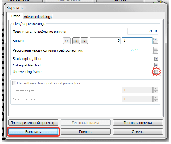
6. В появившемся меню нажмите кнопку ВЫРЕЗАТЬ.
Чтобы убрать рамку снимите галочку (выделено звездочкой) в строке USE WEEDING FRAME
7. Плоттер сразу начнет резать после отправки файла.
В ГРАФИЧЕСКОМ РЕДАКТОРЕ CorelDraw:
1. Создайте макет в графическом редакторе
2. Зайдите в приложения и нажмите SEND TO SIGNCUT
3. Откроется интерфейс программы SIGNCUT
4. Выровняйте изображение по листу кнопкой
5. Отправьте на резку макет, нажав кнопку
Фрезерный станок ЧПУ VENO K45MT2040
Рабочее поле: 2000х4000 мм. Мощность шпинделя: 4,5 кВт. Цанговый патрон: ER-32. Высота портала:…
Перейти в корзинуПерейти в карточку товара
Лазерный станок CO2 по металлу KAMACH 1390 ZET
Рабочее поле, мм: 1300х900. Мощность излучателя, Вт: 130-160 RECI w6. Система управления RuiDa…
Перейти в корзинуПерейти в карточку товара
Лазерный станок по металлу VENO 1530 GE II 1000
Мощность лазера: 1000 Вт. Рабочее поле: 3000х1500 мм. Источник: Maxphotonics. Опция: RayCus, IPG….
Перейти в корзинуПерейти в карточку товара
Товар добавлен в корзину
6. В появившемся меню нажмите кнопку ВЫРЕЗАТЬ.
Чтобы убрать рамку снимите галочку (выделено звездочкой) в строке USE WEEDING FRAME
7. Плоттер сразу начнет резать после отправки файла.
Последние добавленные макеты

Слова Love (любовь)
Приглашение резное из бумаги
Колесо для Хомяка
Гамак лежак для кошек и собак
Макеты брелоков «Гос-Номер», дерево и кожа
Макет нард для лазерного ЧПУ станка
Смотреть все
Welcome to the SignCut family! It all starts with establishing the communication between your cutter and the program. You will find a Start-Up Guide* within the program that should aid in setting up the plotter easily.

 *The Start-Up Guide is available for Pro 2 version 1.479 and higher.
Incase the start-up guide is not available in your current Pro 2 version, please open SignCut and click on the Cutter button and enter your cutting plotter’s Manufacturer, Cutter (model), and Output Device.

If you aren’t sure which output device to choose, please refer to the following instructions to make sure that you are
using the correct communication settings:
1. Unplug the cutter,
2. Restart SignCut Pro 2.
3. Click on the Cutter button
4. Click on the Output Device/Port‘s drop-down menu and take note of the options listed
5. Plug the cutter back in and turn the power on.
6. Close the Cutter dialogue and open it again. Check the Output Device/Port section and a new port option should now appear. This is the port for your cutter, please select it.
7. Walk over to your cutting plotter and look for a setting in the display called Baud or BR and check what value it is set to.
8. Go back to your computer and enter the same value in SignCut’s Cutter dialogue.
The communication should now be correct. To make a test cut, select the red layer of the SignCut logo by clicking the red button on the color panel on the right side of your Pro 2 screen.


If no new output option shows up it means that you have to install the communication driver for your cutting plotter. You should have received it together with your cutter on a CD or it should be available on the website of the reseller or the manufacturer of your machine.
If you cannot find the correct driver, some cutters have driver links provided on the Cutter Information section of Pro 2. You may also refer to our driver download page here.

You may proceed to import your own design for cutting by clicking on the Folder icon or through the File menu -> Open.

Please make sure that your files are properly vectorized before opening in SignCut. The application will only be able to support the following files:
1. SignCut (.sc)
2. SignCut Pro 2 (scpro2)
3. Ai — Adobe Illustrator (.ai) — Best format to use in Illustrator 8 version Exporting Format: Illustrator 8
4. EPS — Encapsulated PostScript (.eps)
5. PS — Postscript (.ps)
6. CDR — Corel Draw (.cdr)
7. PDF — Portable Document Format (.pdf)
8. SVG — Scalable Vector Graphic (.svg)
9 EMF — Enhanced Windows Metafile (.emf)
11. DXF — Autocad Drawing Exchange Format (.dxf)
12. HPGL — Hewlett Packard Graphic Language (.plt)
13. RTF — Rich Text Format (.rtf)
Now, you are all set! If you wish to know more about SignCut and its features, you may visit our Youtube Channel here.
Did you find it helpful?
Yes
No
Send feedback
Sorry we couldn’t be helpful. Help us improve this article with your feedback.
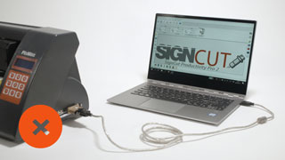
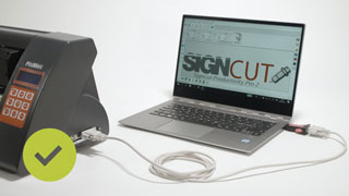
USB Connection
A communication driver must be installed unless the cutting plotter is plug-and-play compatible.

Plug-and-Play
The cutter’s name will show up automatically in the output list in SignCut as a printer, normally, with the name of the manufacturer or model.
Correct way to install the USB-driver
- Install the USB-driver for the cutter. You can find the proper driver on the manufacturer’s or reseller’s website.
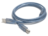
- Once installed, connect the USB-cable as shown in the illustration on the right.
- Power on the cutting plotter and it will show up in the SignCut output list.
Ethernet or TCP/IP Connection
The process to set up the cutting plotter varies. Check the manual for instructions.
Once you have the IP address of the cutter, enter it in SignCut and continue to the next step.
This video shows how to enter the IP address in SignCut. Click to start and watch the video in fullscreen.
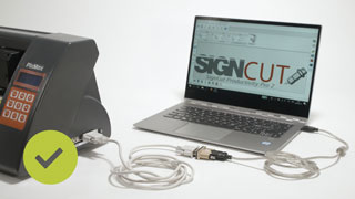
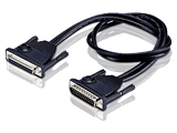
Serial to USB Connection
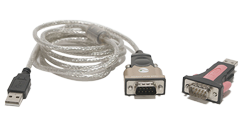
Serial communication is the most stable communication method. If your computer does not have a serial port, you are able to by-pass this through a Serial to USB adapter.
Notice: When using a Serial to USB Adapter, a communication driver must be installed for the computer to recognise it.
Correct way to connect the adapter and serial cable.
- Install the driver that you received with the adapter. If no driver was included, it could usually be found on the manufacturer’s website.
- Connect the adapter and the serial cable between the cutter and computer. See the images below for how to make the correct connection.
- Power on the cutter and it will now show up in the SignCut device list.
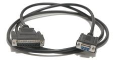
Serial Connection
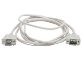
Serial communication is the most stable communication method. If you have both a cutter and a computer with a serial port, use a serial cable to connect the cutter to the computer. When direct serial communication is used, you do not need to install a driver. The option is shown in the SignCut device list as COM1 or COM2.
Follow these steps to connect the cutting machine to the computer.
- Connect the serial cable to the cutter.
- Connect the other end to the computer.
- Power on the cutter.
- Select the
COM portfrom the SignCut device list.
If the cutter has a serial port, but the computer doesn’t, you can use a Serial to USB converter. Click on Serial to USB tab for setup instructions.
Parallel to USB Connection
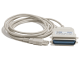
Parallel connection is considered outdated because most modern computers do not have parallel ports. For cutters which only have a parallel port, there are Parallel to USB adapters available which means that the cutter can be used with any Windows operating systems.
Note: This does not work with Mac operating systems.
We recommend adapters with FTDI-chip as it is the only type of adapter we support.
Follow these steps to connect the cutter to the computer.
- Install the driver for the adapter.
- Connect the parallel end of the adapter to the cutter.
- Connect the USB end of the adapter to the computer.
- Power on the cutter and it will now show up in the SignCut device list.
- Click OK to close the dialogue.
Parallel Connection
When direct parallel communication is used, you do not need to install a driver.
Follow these steps to connect the cutter to the computer.
- Connect the parallel cable to the cutter.
- Connect the other end to the computer.
- Power on the cutter and it will show up in the SignCut device list.
If no LTP is shown, follow the instructions below.
-
Open the
Control Paneland clickDevice and Printers. -
Click
Add a Printer. -
Click
The printer that I want isn't listed. -
Click
Add a local printerthen click Next. -
Click
Use an existing portandselect LPT1 in the list. Click Next. -
As for the manufacturer, select
Generic, and for the printer, chooseGeneric/text only. Click Next. -
Name the cutter and click Next to install the driver.
-
Choose if you want to share the cutter onto the network and click Next.
Note:We recommend that you do not do this if you are only going to use it on one computer. -
Do not click
Print out a test pageas the cutter can not print. Click Finish instead.
If the cutter has a parallel port, but the computer does not, you can use a Parallel to USB Converter. Click on the Parallel to USB tab for setup instructions.
Click «Next» to continue to the next section.
-
Contents
-
Table of Contents
-
Troubleshooting
-
Bookmarks
Quick Links
You can expect updates to this manual over the next few months
Do NOT read this entire manual… unless you want to.
•
At the start of Chapters 1 — 4 are short sections with references to find what you need plus some important
reminders. PLEASE read these short sections at the very least and refer back to them, when needed.
•
Chapters 1 and 2 are very important in terms of correctly setting up your Skycut to work with SignCut Pro2
and learning the ins and outs of cutting.
•
Chapter 3 is for those owners wanting to perform print and cut applications.
•
Chapter 4 covers using Skycut accessory tools and dual head applications.
•
Chapter 5 covers several SignCut Pro2 functions of interest: creating contour cuts and engraving fills.
It’s not practical to print this entire manual because:
•
It’s a waste of paper and ink if you only ever need certain sections.
•
The live links to videos and web sites in the manual will not work.
•
This manual will be updated from time to time.
•
You cannot search on individual words.
Also:
•
Videos of interest can be found at the following link:
________________________________________________________________
© 2018-2020
Sandy McCauley All Rights Reserved
Skycut Series D with SignCut Pro2
July 3, 2020
Skycut Support Videos
1
Summary of Contents for Skycut D Series
-
Contents
-
Table of Contents
-
Troubleshooting
-
Bookmarks
Quick Links
You can expect updates to this manual over the next few months
Do NOT read this entire manual… unless you want to.
•
At the start of Chapters 1 — 4 are short sections with references to find what you need plus some important
reminders. PLEASE read these short sections at the very least and refer back to them, when needed.
•
Chapters 1 and 2 are very important in terms of correctly setting up your Skycut to work with SignCut Pro2
and learning the ins and outs of cutting.
•
Chapter 3 is for those owners wanting to perform print and cut applications.
•
Chapter 4 covers using Skycut accessory tools and dual head applications.
•
Chapter 5 covers several SignCut Pro2 functions of interest: creating contour cuts and engraving fills.
It’s not practical to print this entire manual because:
•
It’s a waste of paper and ink if you only ever need certain sections.
•
The live links to videos and web sites in the manual will not work.
•
This manual will be updated from time to time.
•
You cannot search on individual words.
Also:
•
Videos of interest can be found at the following link:
________________________________________________________________
© 2018-2020
Sandy McCauley All Rights Reserved
Skycut Series D with SignCut Pro2
July 3, 2020
Skycut Support Videos
1
Summary of Contents for Skycut D Series
USB Connection
A communication driver must be installed unless the cutting plotter is plug-and-play compatible.
Plug-and-Play
The cutter’s name will show up automatically in the output list in SignCut as a printer, normally, with the name of the manufacturer or model.
Correct way to install the USB-driver
- Install the USB-driver for the cutter. You can find the proper driver on the manufacturer’s or reseller’s website.
- Once installed, connect the USB-cable as shown in the illustration on the right.
- Power on the cutting plotter and it will show up in the SignCut output list.
Ethernet or TCP/IP Connection
The process to set up the cutting plotter varies. Check the manual for instructions.
Once you have the IP address of the cutter, enter it in SignCut and continue to the next step.
This video shows how to enter the IP address in SignCut. Click to start and watch the video in fullscreen.
Serial to USB Connection
Serial communication is the most stable communication method. If your computer does not have a serial port, you are able to by-pass this through a Serial to USB adapter.
Notice: When using a Serial to USB Adapter, a communication driver must be installed for the computer to recognise it.
Correct way to connect the adapter and serial cable.
- Install the driver that you received with the adapter. If no driver was included, it could usually be found on the manufacturer’s website.
- Connect the adapter and the serial cable between the cutter and computer. See the images below for how to make the correct connection.
- Power on the cutter and it will now show up in the SignCut device list.
Serial Connection
Serial communication is the most stable communication method. If you have both a cutter and a computer with a serial port, use a serial cable to connect the cutter to the computer. When direct serial communication is used, you do not need to install a driver. The option is shown in the SignCut device list as COM1 or COM2.
Follow these steps to connect the cutting machine to the computer.
- Connect the serial cable to the cutter.
- Connect the other end to the computer.
- Power on the cutter.
- Select the
COM portfrom the SignCut device list.
If the cutter has a serial port, but the computer doesn’t, you can use a Serial to USB converter. Click on Serial to USB tab for setup instructions.
Parallel to USB Connection
Parallel connection is considered outdated because most modern computers do not have parallel ports. For cutters which only have a parallel port, there are Parallel to USB adapters available which means that the cutter can be used with any Windows operating systems.
Note: This does not work with Mac operating systems.
We recommend adapters with FTDI-chip as it is the only type of adapter we support.
Follow these steps to connect the cutter to the computer.
- Install the driver for the adapter.
- Connect the parallel end of the adapter to the cutter.
- Connect the USB end of the adapter to the computer.
- Power on the cutter and it will now show up in the SignCut device list.
- Click OK to close the dialogue.
Parallel Connection
When direct parallel communication is used, you do not need to install a driver.
Follow these steps to connect the cutter to the computer.
- Connect the parallel cable to the cutter.
- Connect the other end to the computer.
- Power on the cutter and it will show up in the SignCut device list.
If no LTP is shown, follow the instructions below.
-
Open the
Control Paneland clickDevice and Printers. -
Click
Add a Printer. -
Click
The printer that I want isn't listed. -
Click
Add a local printerthen click Next. -
Click
Use an existing portandselect LPT1 in the list. Click Next. -
As for the manufacturer, select
Generic, and for the printer, chooseGeneric/text only. Click Next. -
Name the cutter and click Next to install the driver.
-
Choose if you want to share the cutter onto the network and click Next.
Note:We recommend that you do not do this if you are only going to use it on one computer. -
Do not click
Print out a test pageas the cutter can not print. Click Finish instead.
If the cutter has a parallel port, but the computer does not, you can use a Parallel to USB Converter. Click on the Parallel to USB tab for setup instructions.
Click «Next» to continue to the next section.
Последние добавленные макеты

Резной наличник
Меч «Оскверненный испепелитель»
Клинок «Ледяная скорбь»
Набор из 100 вариантов топперов на все случаи жизни
Копилка — джойстик
Макет ключницы с дверью под 4 мм
Смотреть все