- Manuals
- Brands
- Simrad Manuals
- Marine Equipment
- AP70 MK2
- Operator’s manual
-
Contents
-
Table of Contents
-
Bookmarks
Quick Links
AP70 MK2
Operator Manual
ENGLISH
navico-commercial.com
Related Manuals for Simrad AP70 MK2
Summary of Contents for Simrad AP70 MK2
-
Page 1
AP70 MK2 Operator Manual ENGLISH navico-commercial.com… -
Page 3
Implementing Regulation (EU) 2018/773 (MED) — Wheelmark Ú Note: The AP70 MK2 system is Wheelmark approved only when installed according to the relevant AP70 MK2 MED-B certificate. The relevant declaration of conformity and certificates are available in the product’s section at the following website: www.navico-commercial.com… -
Page 4
This manual is written for software version 1.0. The manual is continually updated to match new software releases. The latest available manual version can be downloaded from the following website: • www.navico-commercial.com Change log Part no Date and description 2019-Jan-11 988-12375-001 First version. Preface | AP70 MK2 Operator Manual… -
Page 5: Table Of Contents
Possible alerts and corrective action 44 Maintenance Preventive maintenance Cleaning the display unit Cleaning the media port door Checking the connectors Restoring factory default settings Backup and restore of system data Software updates 47 Menu overview Quick menus Contents | AP70 MK2 Operator Manual…
-
Page 6
Settings 50 Terms and abbreviations Contents | AP70 MK2 Operator Manual… -
Page 7: Introduction
Starboard (confirm) key Menu and dialog operation • press to confirm/enter next menu level In Standby mode: • press to activate NFU mode In automatic modes: • press to change set heading/set course to starboard Introduction | AP70 MK2 Operator Manual…
-
Page 8: Usb Port
The USB port can be used to: • connect a storage device The USB devices should be standard PC compatible hardware. When not in use, the protective door should always be securely shut to prevent possible water ingress. Introduction | AP70 MK2 Operator Manual…
-
Page 9: The Autopilot Page
If the autopilot is operated from another control unit, the passive icon is shown in the mode indication field. If the autopilot is controlled by an external system selector, the mode indication will be replaced as below. Introduction | AP70 MK2 Operator Manual…
-
Page 10
If sensor input is missing, the numbers will be replaced with hyphens. Rudder bar Rudder position indicator with digital and analog readout. Direction indicator (A) is shown when rudder movement is commanded and rudder feedback is available. Introduction | AP70 MK2 Operator Manual… -
Page 11: Basic Operation
The autopilot will then go to Standby mode and display Override to indicate the steering is from the helm. Autosteering can be resumed by pressing the AUTO or the WORK key. Basic operation | AP70 MK2 Operator Manual…
-
Page 12: The Pendulum Feature
A passive unit is indicated with a passive icon in the mode status field. On a passive/locked unit illumination can be adjusted, alert sound can be locally silenced, and the Command key can be used for requesting command. All other functions are unavailable. Basic operation | AP70 MK2 Operator Manual…
-
Page 13: The Menu System
Press the power key Ú Note: All changes made to the display setup will apply to all units belonging to the same display group. For more information about network groups, refer to the separate Installation manual. Basic operation | AP70 MK2 Operator Manual…
-
Page 14: Selecting Autopilot Mode
— The selection times out and triggers the work profile shift. You can also confirm your selection by pressing the rotary knob. The name of the work profile in use is displayed in the mode status panel. Working with thrusters Thruster(s) can be connected to the autopilot system. Basic operation | AP70 MK2 Operator Manual…
-
Page 15
When a thruster is installed and activated in the work profile, the thruster status icon and the thruster information in the mode info panel are as shown below. • Thruster available for present work profile, no thrust applied Basic operation | AP70 MK2 Operator Manual… -
Page 16
• Thruster in use. Image including thrust direction • Thruster manually deselected • Thruster unavailable (vessel speed is above inhibit limit) Basic operation | AP70 MK2 Operator Manual… -
Page 17: Delegation Of Control In Multiple Station Systems
— All passive units will be opened for command transfer, indicated as below — The lock function will be deactivated, and the lock symbol removed from all units Take command on selected remote unit Delegation of control in multiple station systems | AP70 MK2 Operator Manual…
-
Page 18: Master Systems
In the illustration the main bridge is defined as master station. One QS80, and two AP70 MK2 control units are included in the master station. One of the AP70 MK2 control units is defined as the Master unit.
-
Page 19
— The requesting unit will now be opened for command transfer. Other units will remain locked Press the Command key on the unit requesting command — Command will be transferred to this unit, accompanied by a 2 seconds sound Delegation of control in multiple station systems | AP70 MK2 Operator Manual… -
Page 20: Autopilot Modes
You toggle between Auto and NoDrift mode by repeated presses on the Auto key. The selection times out and triggers the mode shift. You can also confirm your selection by pressing the Starboard key or the rotary knob. Autopilot modes | AP70 MK2 Operator Manual…
-
Page 21
You can close the dialog at any time without disturbing the pre-setting or the execution of a turn. If closed, the dialog is recalled by turning the rotary knob. Autopilot modes | AP70 MK2 Operator Manual… -
Page 22
If you don’t respond within 3 seconds the menu will disappear, and the autopilot will go to AUTO mode with current heading as set heading. Quick menu in AUTO mode From the Quick menu in AUTO mode you can change rudder parameters and set manual speed. Autopilot modes | AP70 MK2 Operator Manual… -
Page 23
From the Quick menu in NoDrift mode you can change the track response, rudder parameters and set manual speed. Turn patterns The system includes the following turn patterns: • U-turn • S-turns (optional) Autopilot modes | AP70 MK2 Operator Manual… -
Page 24
Makes the vessel yaw around the main heading. When activated, the autopilot is switched to S-turns mode. Turn variables: • Course change • Turn radius S-turn settings The S-turn settings can be set as default values. Autopilot modes | AP70 MK2 Operator Manual… -
Page 25: Nav Mode
If the required course change to the next waypoint is less than the course change limit, the autopilot will automatically change the course. The dialog will disappear after 8 seconds unless cleared by the X key. Autopilot modes | AP70 MK2 Operator Manual…
-
Page 26
The intention is to make the autopilot start the heading change in due time to make a smooth turn onto the next leg. The figure below may be used to select the appropriate arrival circle when creating the route. Autopilot modes | AP70 MK2 Operator Manual… -
Page 27: Controlling Steering Performance In Automatic And Navigational Modes
If the value is set too high the overshoot will increase and the steering will be unstable. Autopilot modes | AP70 MK2 Operator Manual…
-
Page 28
Speed If neither boat speed nor SOG data are available and/or deemed unreliable, a manual value for speed can be entered and used by the autopilot to aid steering calculations. Autopilot modes | AP70 MK2 Operator Manual… -
Page 29: Simulator Mode
It is not possible to simulate commissioning and setup. If the unit is turned off while in simulator mode, this mode will still be active on next power Active simulator mode is indicated with a flashing notification on the image. Autopilot modes | AP70 MK2 Operator Manual…
-
Page 30: Work Profiles
A work profile is a set of steering parameters. You can change the active work profile to adapt the autopilot steering characteristics to different operational conditions. The AP70 MK2 has a set of predefined work profiles, depending on selected boat type. There can be up to 6 work profiles defined in the system.
-
Page 31
If the value is set too high the overshoot will increase and the steering will be unstable. Work profiles| AP70 MK2 Operator Manual… -
Page 32
Controls how fast the autopilot will apply rudder to compensate for a constant heading offset, e.g. when external forces such as wind or current affects the heading. Lower autotrim will give faster elimination of a constant heading offset Work profiles| AP70 MK2 Operator Manual… -
Page 33
Defines the vessel’s accepted offset distance from the track. If the vessel goes beyond this limit an alarm will be activated. Drive select Defines which drives that shall be used for the selected work profile. Rudder Work profiles| AP70 MK2 Operator Manual… -
Page 34
When the feature is enabled, one rudder will stop moving before the other one if max./ min. rudder angles are demanded. When the feature is enabled, the rudder bar shows rudder command instead of measured rudder angle. Work profiles| AP70 MK2 Operator Manual… -
Page 35
The system includes a number of icons that can be used to identify the profile settings. Exporting and importing work profiles It is possible to export and import a work profile to/from a USB stick. Work profiles| AP70 MK2 Operator Manual… -
Page 36: The Alert System
Descriptive text Active — not acknowledged, • No audible signal silenced Alarm • Descriptive text Active — acknowledged • No audible signal • Descriptive text Rectified — not acknowledged • No audible signal The alert system| AP70 MK2 Operator Manual…
-
Page 37: Acknowledging A Message
There is no time-out on the alarm message or siren. They remain active until you acknowledge the alarm or until the reason for the alarm is removed. Alert dialogs Active alerts List of all active alerts. The alert system| AP70 MK2 Operator Manual…
-
Page 38: Setting The Alert And Warning Limits
When monitor compass is available Alarm for main compass failure is given and steering continues using monitor compass. If there is a difference between the compasses, a smooth transition (2 min. filter) to the The alert system| AP70 MK2 Operator Manual…
-
Page 39
When control unit(s) and CAN bus have different power source, alarm will be given on active control unit with sound and flashing red power button led (display will go “black”). Main steering computer will go to Standby mode and activate alarm on all other control units. The alert system| AP70 MK2 Operator Manual… -
Page 40: Possible Alerts And Corrective Action
Check summary unit loads • Check for short circuit/defective device on network Check heading (W) Jump in heading of more than 10°/second. • Check steering compass • Change to other heading source or monitor compass The alert system| AP70 MK2 Operator Manual…
-
Page 41
— If LED is on, try to restart unit by turning power off/on End of route (A) Activated on the active control unit when an end route waypoint name has been received from the Plotter/ECS. The alert system| AP70 MK2 Operator Manual… -
Page 42
Check all connections • Check rudder feedback transmission link (not applicable for Virtual feedback installations) • Check drive unit motor/brushes • For SD80, check that port/stbd led is activated (ref label in cover for location The alert system| AP70 MK2 Operator Manual… -
Page 43
The vessel speed exceed the set limit for when the thruster can be used. Ú Note: The Thruster inhibit limit will only apply when speed source is Log or SOG, not if the speed is set manually. The alert system| AP70 MK2 Operator Manual… -
Page 44: Maintenance
Unless you need to clear all stored values during the installation setup procedure, you should not perform a restore of factory settings. Backup and restore of system data The system includes a backup and restore function, making it possible to back-up and restore user settings. Maintenance| AP70 MK2 Operator Manual…
-
Page 45: Software Updates
To update this unit or a connected device: • Select the update file in the dialog Ú Note: Do not turn off the unit or a connected device until the update is completed, or until you are prompted to restart the unit. Maintenance| AP70 MK2 Operator Manual…
-
Page 46
Maintenance| AP70 MK2 Operator Manual… -
Page 47: Menu Overview
These menu options are used for manually adjusting steering performance. The menu options are described in «Controlling steering performance in automatic and navigational modes» on page 27. Auto mode Level 1 Level 2 Rudder (Adjust) Counter rudder (Adjust) Speed (Adjust) Settings (Settings dialogs/menus) Menu overview| AP70 MK2 Operator Manual…
-
Page 48
Settings During installation the system is configured, most system settings are defined, and the system is commissioned. All system configuration and Installation setup is described in the separate AP70 MK2 Installation manual. To access the Settings menu: • press the Menu key twice. -
Page 49
Network Sources > Auto select Steering compass > Navigation > Position > Boat speed > Depth > Autopilot computer > Device list… Diagnostics Groups > Display Units Damping Station Damping > Heading Boat speed Menu overview| AP70 MK2 Operator Manual… -
Page 50
Bearing Waypoint To Waypoint Course Over Ground Course To Steer Course Distance to next waypoint Follow-Up mode Non Follow-Up mode Heading Magnetic Speed Over Ground Speed Through Water Waypoint name or number Cross track distance Terms and abbreviations| AP70 MK2 Operator Manual… -
Page 52
www.navico-commercial.com…
Preface
Disclaimer
As Navico is continuously improving this product, we retain the right to make changes to the
product at any time which may not be reflected in this version of the manual. Please contact
your nearest distributor if you require any further assistance.
It is the owner’s sole responsibility to install and use the equipment in a manner that will not
cause accidents, personal injury or property damage. The user of this product is solely
responsible for observing maritime safety practices.
NAVICO HOLDING AS AND ITS SUBSIDIARIES, BRANCHES AND AFFILIATES DISCLAIM ALL
LIABILITY FOR ANY USE OF THIS PRODUCT IN A WAY THAT MAY CAUSE ACCIDENTS, DAMAGE
OR THAT MAY VIOLATE THE LAW.
This manual represents the product as at the time of printing. Navico Holding AS and its
subsidiaries, branches and affiliates reserve the right to make changes to specifications
without notice.
Governing language
This statement, any instruction manuals, user guides and other information relating to the
product (Documentation) may be translated to, or has been translated from, another
language (Translation). In the event of any conflict between any Translation of the
Documentation, the English language version of the Documentation will be the official
version of the Documentation.
Trademarks
®
Navico
is a registered trademark of Navico Holding AS.
®
Simrad
is used by license from Kongsberg.
Copyright
Copyright © 2019 Navico Holding AS.
Warranty
The warranty card is supplied as a separate document. In case of any queries, refer to the
brand website of your unit or system:
www.navico-commercial.com
Compliance statements
Navico declare under our sole responsibility that the product conforms with the
requirements of:
•
C-tick
•
CE under EMC Directive 2014/30/EU
•
European Council Directive 2014/90/EU on Marine Equipment modified by Commission
Implementing Regulation (EU) 2018/773 (MED) — Wheelmark
Ú Note:
The AP70 MK2 system is Wheelmark approved only when installed according to
the relevant AP70 MK2 MED-B certificate.
The relevant declaration of conformity and certificates are available in the product’s section
at the following website:
www.navico-commercial.com
Preface
| AP70 MK2 Operator Manual
3

AP70/AP80
QuickStart Guide
The front panel
TURN
MENUCMD
STBY AUTO NAV WORK
ALARM
ALARM
13
1 3
2
4
5 6
7
12
108
No. Description
1 CMD/Thruster. Press once to take/request command. Press and hold to activate/
deactivate available thrusters
2 MENU. Press once to display the active steering mode’s quick menu. Press twice to
display the Settings menu
3 PWR/Light. Press to display the Light dialog. Press and hold to turn the unit ON/
OFF
4 Course knob. In menus; turn to select menu item and adjust value, press to
confirm. In FU mode; turn to set rudder angle. In STBY and NFU mode; press to go
to FU mode. In AUTO and NoDrift mode; turn to change set heading/set course,
press to capture present heading. In NAV/TRACK mode, turn to set track offset
5 PORT. In menus; press to return to previous menu level. In STBY and FU modes;
press to go to NFU mode. In AUTO and NoDrift modes; press to change set
heading/set course to port
6 STBD. In menus; press to confirm menu selection/enter next menu level. In STBY
and FU modes; press to go to NFU steering. In AUTO and NoDrift modes; press to
change set heading/set course to starboard
7 TURN. Press to display the Turn dialog
8 STBY. Press to switch the autopilot to Standby mode
9 AUTO. Press to activate Auto or NoDrif t mode
10 NAV/TRACK. Press to activate NAV/TRACK (AP80) steering modes
11 WORK. Press to display the Work profile dialog
12 ALARM. Press to display the Alarm dialog (AP80 only)
13 USB connector (AP80 only)
EN
Смотреть руководство для Simrad AP70 Autopilot ниже. Все руководства на ManualsCat.com могут просматриваться абсолютно бесплатно. Нажав кнопку «Выбор языка» вы можете изменить язык руководства, которое хотите просмотреть.

MANUALSCAT | RU
Вопросы и ответы
У вас есть вопрос о Simrad AP70 Autopilot, но вы не можете найти ответ в пользовательском руководстве? Возможно, пользователи ManualsCat.com смогут помочь вам и ответят на ваш вопрос. Заполните форму ниже — и ваш вопрос будет отображаться под руководством для Simrad AP70 Autopilot. Пожалуйста, убедитесь, что вы опишите свои трудности с Simrad AP70 Autopilot как можно более детально. Чем более детальным является ваш вопрос, тем более высоки шансы, что другой пользователь быстро ответит на него. Вам будет автоматически отправлено электронное письмо, чтобы проинформировать вас, когда кто-то из пользователей ответит на ваш вопрос.
Задать вопрос о Simrad AP70 Autopilot
- Бренд:
- Simrad
- Продукт:
- без категории
- Модель/название:
- AP70 Autopilot
- Тип файла:
- Доступные языки:
- английский
Сопутствующие товары Simrad AP70 Autopilot
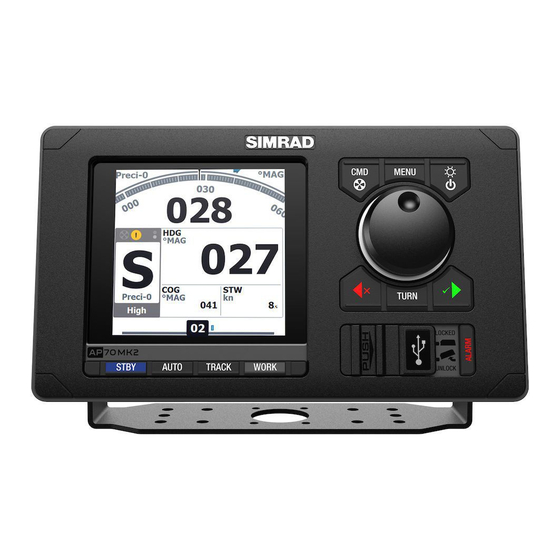
The AP70 Mk2 is a dedicated autopilot controller designed to meet the needs of professional mariners aboard a variety of commercial vessels.
Replacing both the AP70 and AP80 as our IMO/SOLAS autopilot controller, the AP70 Mk2 retains much of the well-reputed platform of its predecessors, but with a brilliant new display and modernised software interface.
The AP70 Mk2 accommodates installations with up to six drives. Previously only available with the AP80, this premium feature is now a standard in the AP70 Mk2.
Engineered for responsiveness, robustness and ease of use, the AP70Mk2 pairs a precision rotary control dial with dedicated buttons for instant access to steering modes, several custom-configurable work modes and multiple rudder/thruster integration.
Wheelmarked for use on SOLAS vessels
The AP70 Mk2 builds on, and continues the legacy of the SIMRAD Pro autopilot product portfolio. Its performance, robustness and quality are proven and recognised with the wheelmark symbol, making it suitable for all vessels ranging from small work- boats to large tankers.
Advanced configuration and tuning options to suit all ships
Parameters ranges and tuning options to support vessel dynamics. Adjustable for all weather conditions, hull types, work situations. Suitable for retro-fit on old ships as well as modern new-builds.
Compatible with all common rudder/drive types
Water jet, Azi-pods, Voith-Schneider, Rudder, outboard. Control signals to control, hydraulic pumps, solenoids, analog current/voltage, control/handshake signals.
Up to 6 rudders/thrusters integration
Dual rudders, fore and aft thrusters supports large and complex installations and redundancy.
Heavy-duty rudder feedback support
Simrad heavy-duty rudder feedbacks are supported.
Configurable Work Mode and Low/High Speed Modes
Autopilot settings can be tuned for optimal performance in separate low-speed, high-speed, and Work modes. The user-configurable Work mode allows the autopilot system to be configured for optimal response in a specific situation, such as a fully laden vessel, configurable thruster usage.
No Drift Steering
No Drift mode integrates GPS navigation with auto-steering, using position data to counteract the effects of wind and tide. This allows the AP70 Mk2 to maintain a straight track over ground on the current course, without the need to manually set a waypoint or route.
Navigation steering, route following
Navigation steering controls the ship on a pre-planned route from a Simrad MFD, Simrad ECDIS or third party MFD and ECDIS.
Command transfer and multiple control stations support
Command transfer is a mechanism useful in multi-controller installations. It enables the officer on watch to allow, deny the transfer of autopilot control to control devices such as a secondary AP70 Mk2 or a remote controller on a bridge wing station, above deck, or aft bridge depending on the work scenario. The AP70 Mk2 can also be used in an open configuration, where control flow is unrestricted.
Key Features
- Wheelmarked for use on board SOLAS vessels (IMO, MED-B)
- Advanced configuration and tuning options to suit all ships
- Compatible with all common rudder/drive types
- Up to 6 rudders/thrusters integration
- Heavy-duty rudder feedback support
- Configurable work modes and low/high speed modes
- No Drift steering holds course against wind and tide
- Navigation steering, route following
- Command transfer and multiple control stations support
Table of Contents for Simrad AP70 MK2:
-
Terms and abbreviations The following tables holds a list of abbreviations used in the autopilot display. BWW Bearing Waypoint To Waypoint COG Course Over Ground CTS Course To Steer CRS Course DTW Distance to next waypoint FU Follow-Up mode NFU Non Follow-Up mode HDG Heading MAG Magnetic SOG Speed Over Ground STW Speed Through Water WPT Waypoint name or number XTD Cross track distance 9 50 Terms and abbreviations| AP70 MK2 Operator Manual
-
ENGLISH AP70 MK2 Operator Manual navico-commercial.com
-
About this manual This manual is a reference guide for operating the unit. It assumes that all equipment is installed and configured, and that the system is ready to use. Images used in this manual might not exactly match the screen on your unit. Intended audience This manual is written for system operators. The manual assumes that the reader has basic knowledge about this type of equipment in regards to: • operation • nautical terminology and practices Important text conventions Important text that requires special attention from the reader is emphasized
-
CAN bus supply voltage missing Active control unit will give local alarm and rudder/thruster drive units will go to Standby mode. Autopilot computer missing rudder/thruster drive computer failure Alarm will be given and the ready signal to the steering /thruster gear will disappear. If software failure, there will be a watchdog restart of failing drive computer. The autopilot steering computer will try to maintain steering as far as possib
-
Engage output overload (W/A) (Warning when current >3.5 A. Alarm when current > 5 A). Bypass valve or clutch is drawing excessive current. • Ensure there is no shortage to ground or cabling damage • Disconnect cable from autopilot computer to motor, and make sure there is no alarm when engaging FU or AUTO mode EVC Com error (A) Lost communication with EVC system (Volvo IPS and similar). • Check connection with EVC e
-
Backlight level Adjusts the backlight level. When the dialog is active, you can cycle the preset backlight levels by short presses on the power key. Night mode color Sets the night mode color palette. Selecting autopilot mode • Standby mode or Nav mode: press the Standby or Track key • Auto mode or NoDrift mode: press the Auto key — last active mode (Auto or NoDrift) is activated immediately, and the mode pop-up menu is displayed • repe
-
The default values can be changes at any time when the boat is in a turn. NAV mode Ú Note: NAV mode requires a compatible navigator connected to the network. It is not possible to select NAV mode if heading information is missing, or if steering information is not received from the external chartplotter. In NAV mode the autopilot uses steering information from an external navigator to direct the vessel to o
-
Type Icon State Indication Warning Active — not acknowledged, not silenced • Descriptive text • Audible signal Active — not acknowledged, silenced • Descriptive text • No audible signal Active — acknowledged • Descriptive text • No audible signal Rectified — not acknowledged • Descriptive text • No audible signal Acknowledging a message An alert dialog showing a single message have one or two options for acknowledging the message: • ACK / Acknowledge Sets the alarm state to acknowledged, m
-
In a Master system command can be transferred to a remote unit either by opening the system for remote operation from the Master unit, or by requesting command from one of the remote units. Ú Note: You can at any time return to control from the Master station by pressing the Command key on one of the units in the master station. Opening a Master system for operation from a remote unit 1. Press the Command key on the Master unit 2. Accept the command request on the master unit — The system will now be open and command can be
-
monitor compass heading takes place. When acknowledging the alarm, the autopilot goes to Standby mode. When monitor compass is not available Rudder is kept at fixed angle (i.e. heading is approximately maintained if failing when heading keeping, turn is approximately maintained if failing when turning), alarm is given and autopilot goes to Standby mode. Magnetic variation missing If heading source is set to be adjusted for magnetic variation, variation is taken from available sensors in follow
-
Work profiles A work profile is a set of steering parameters. You can change the active work profile to adapt the autopilot steering characteristics to different operational conditions. The AP70 MK2 has a set of predefined work profiles, depending on selected boat type. There can be up to 6 work profiles defined in the system. During commissioning and seatrial the parameters for active profile will be tuned for optimized steering performance. Predefined profiles Normal profile This is the de
-
*988-12375-001* www.navico-commercial.com
-
48 Settings 50 Terms and abbreviations 6 Contents | AP70 MK2 Operator Manual
-
Preface Disclaimer As Navico is continuously improving this product, we retain the right to make changes to the product at any time which may not be reflected in this version of the manual. Please contact your nearest distributor if you require any further assistance. It is the owner’s sole responsibility to install and use the equipment in a manner that will not cause accidents, personal injury or property damage. The user of this product is solely responsible for observing maritime safety practices. NAVICO HOLDING AS AND ITS SU
-
Level 1 Level 2 Level 3 Alerts Active alerts… Alert history… Alert settings > Compass difference limit Units Distance Distance small Speed Heading Network Sources > Auto select Steering compass > Navigation > Position > Boat speed > Depth > Autopilot computer > Device list… Diagnostics Groups > Display Units Damping Station Damping > Heading Boat speed SOG COG Menu overview| AP70 MK2 Operator Manual 49
-
Basic operation Safe operation with the autopilot Warning: An autopilot is a useful navigational aid, but DOES NOT replace a human navigator. Warning: Ensure the autopilot has been installed correctly, commissioned and calibrated before use. Do not use automatic steering when: • In heavy traffic areas or in narrow waters • In poor visibility or extreme sea conditions • When in areas where use of an autopilot is prohibited by law When using an autopilot: • Do not leave the helm unattended • Do not place any magnetic mat
Questions, Opinions and Exploitation Impressions:
You can ask a question, express your opinion or share our experience of Simrad AP70 MK2 device using right now.
Preface
Disclaimer
As Navico is continuously improving this product, we retain the right to make changes to the
product at any time which may not be reflected in this version of the manual. Please contact
your nearest distributor if you require any further assistance.
It is the owner’s sole responsibility to install and use the equipment in a manner that will not
cause accidents, personal injury or property damage. The user of this product is solely
responsible for observing maritime safety practices.
NAVICO HOLDING AS AND ITS SUBSIDIARIES, BRANCHES AND AFFILIATES DISCLAIM ALL
LIABILITY FOR ANY USE OF THIS PRODUCT IN A WAY THAT MAY CAUSE ACCIDENTS, DAMAGE
OR THAT MAY VIOLATE THE LAW.
This manual represents the product as at the time of printing. Navico Holding AS and its
subsidiaries, branches and affiliates reserve the right to make changes to specifications
without notice.
Governing language
This statement, any instruction manuals, user guides and other information relating to the
product (Documentation) may be translated to, or has been translated from, another
language (Translation). In the event of any conflict between any Translation of the
Documentation, the English language version of the Documentation will be the official
version of the Documentation.
Trademarks
®
Navico
is a registered trademark of Navico Holding AS.
®
Simrad
is used by license from Kongsberg.
Copyright
Copyright © 2019 Navico Holding AS.
Warranty
The warranty card is supplied as a separate document. In case of any queries, refer to the
brand website of your unit or system:
www.navico-commercial.com
Compliance statements
Navico declare under our sole responsibility that the product conforms with the
requirements of:
•
C-tick
•
CE under EMC Directive 2014/30/EU
•
European Council Directive 2014/90/EU on Marine Equipment modified by Commission
Implementing Regulation (EU) 2018/773 (MED) — Wheelmark
Ú Note:
The AP70 MK2 system is Wheelmark approved only when installed according to
the relevant AP70 MK2 MED-B certificate.
The relevant declaration of conformity and certificates are available in the product’s section
at the following website:
www.navico-commercial.com
Preface
| AP70 MK2 Operator Manual
3
The AP70 Mk2 is a dedicated autopilot controller designed to meet the needs of professional mariners aboard a variety of commercial vessels.
Replacing both the AP70 and AP80 as our IMO/SOLAS autopilot controller, the AP70 Mk2 retains much of the well-reputed platform of its predecessors, but with a brilliant new display and modernised software interface.
The AP70 Mk2 accommodates installations with up to six drives. Previously only available with the AP80, this premium feature is now a standard in the AP70 Mk2.
Engineered for responsiveness, robustness and ease of use, the AP70Mk2 pairs a precision rotary control dial with dedicated buttons for instant access to steering modes, several custom-configurable work modes and multiple rudder/thruster integration.
Wheelmarked for use on SOLAS vessels
The AP70 Mk2 builds on, and continues the legacy of the SIMRAD Pro autopilot product portfolio. Its performance, robustness and quality are proven and recognised with the wheelmark symbol, making it suitable for all vessels ranging from small work- boats to large tankers.
Advanced configuration and tuning options to suit all ships
Parameters ranges and tuning options to support vessel dynamics. Adjustable for all weather conditions, hull types, work situations. Suitable for retro-fit on old ships as well as modern new-builds.
Compatible with all common rudder/drive types
Water jet, Azi-pods, Voith-Schneider, Rudder, outboard. Control signals to control, hydraulic pumps, solenoids, analog current/voltage, control/handshake signals.
Up to 6 rudders/thrusters integration
Dual rudders, fore and aft thrusters supports large and complex installations and redundancy.
Heavy-duty rudder feedback support
Simrad heavy-duty rudder feedbacks are supported.
Configurable Work Mode and Low/High Speed Modes
Autopilot settings can be tuned for optimal performance in separate low-speed, high-speed, and Work modes. The user-configurable Work mode allows the autopilot system to be configured for optimal response in a specific situation, such as a fully laden vessel, configurable thruster usage.
No Drift Steering
No Drift mode integrates GPS navigation with auto-steering, using position data to counteract the effects of wind and tide. This allows the AP70 Mk2 to maintain a straight track over ground on the current course, without the need to manually set a waypoint or route.
Navigation steering, route following
Navigation steering controls the ship on a pre-planned route from a Simrad MFD, Simrad ECDIS or third party MFD and ECDIS.
Command transfer and multiple control stations support
Command transfer is a mechanism useful in multi-controller installations. It enables the officer on watch to allow, deny the transfer of autopilot control to control devices such as a secondary AP70 Mk2 or a remote controller on a bridge wing station, above deck, or aft bridge depending on the work scenario. The AP70 Mk2 can also be used in an open configuration, where control flow is unrestricted.
Key Features
- Wheelmarked for use on board SOLAS vessels (IMO, MED-B)
- Advanced configuration and tuning options to suit all ships
- Compatible with all common rudder/drive types
- Up to 6 rudders/thrusters integration
- Heavy-duty rudder feedback support
- Configurable work modes and low/high speed modes
- No Drift steering holds course against wind and tide
- Navigation steering, route following
- Command transfer and multiple control stations support