-
Contents
-
Table of Contents
-
Bookmarks
Quick Links
Reference manual
Simrad ES60
Fish finding
echo sounder
www.SIMRAD.com
M A X I M I Z I N G
Y O U R
P E R F O R M A N C E
A T
S E A
Related Manuals for Simrad ES60 — REFERENCE MANUAL REV H
Summary of Contents for Simrad ES60 — REFERENCE MANUAL REV H
-
Page 1
Reference manual Simrad ES60 Fish finding echo sounder www.SIMRAD.com M A X I M I Z I N G Y O U R P E R F O R M A N C E S E A… -
Page 3
857-160970 Simrad ES60 Fish finding echo sounder Reference manual… -
Page 4
The information contained in this document is subject to change without prior notice. Simrad Horten AS shall not be liable for errors contained herein, or for incidental or consequential damages in connection with the furnishing, performance, or use of this document. -
Page 5
Reference manual Chapters System description This chapter presents a general description of the echo sounder system. Refer to page 1. Display views This chapter explains the layout of the echo sounder display presentation. Refer to page 12. Getting started This chapter provides an operational example to get you started with the operation. -
Page 6: Table Of Contents
Simrad ES60 Table of contents SYSTEM DESCRIPTION ……..
-
Page 7
Reference manual Environmental parameters ……..Navigation interface . -
Page 8
Simrad ES60 Playback ………. -
Page 9
Reference manual History ……….IP Address . -
Page 10: System Description
System description SYSTEM DESCRIPTION Introduction This chapter provides a brief introduction to the Simrad ES60 fishery echo sounder system. Related topics Overview, page 2 → ES60 System drawing, page 3 → Wave propagation, page 4 → Bottom echo, page 6 →…
-
Page 11: System Overview
Simrad ES60 System overview Key facts The Simrad ES60 echo sounders is designed for the professional fishery community implementing the latest innovations. • The ES60 system is flexible and easy to configure due to the modular design. • Echo sounders ranging from relatively low-cost single beam to large multi-frequency systems containing several split-beam channels can be realised.
-
Page 12
System description System diagram: (A) = LCD monitor (B) = Processor Unit (C) = General Purpose Transceiver (GPT) (D) = Transducer 857-160970 / Rev.H… -
Page 13: Wave Propagation
Simrad ES60 Wave propagation The velocity of sound wave propagation in the sea varies slightly with temperature, salinity and pressure. The velocity varies between 1440 and 1520 m/s in shallow sea water, while a velocity around 1480 m/s can be expected at 1000 m depth. In shallow fresh water the velocity is approximately 1430 m/s.
-
Page 14
System description Propagation losses due to absorption are much higher in sea water than in fresh water. Absorption also increases with frequency. At 38 kHz the absorption is 0.5 dB/km in fresh water and 10 dB/km in sea water. At 200 kHz the absorption is 10 dB/km in fresh water and 50 dB/km in salt water. -
Page 15: Bottom Echo
Simrad ES60 Bottom echo A hard flat bottom reflects the transmitted signal as if it were a mirror. The transmitted pulse hits the illuminated bottom area at nearly the same instant, and the echo from different parts of this area arrive back at the surface also at nearly the same instant.
-
Page 16
System description The bottom detection algorithm locks to the first good bottom return. The depth at point A rather than the depth along the transducer axis will be output for a sloped bottom. The detected depth value is always smaller than the depth along the transducer axis implying that a safety margin is automatically included. -
Page 17: Split- -Beam Operation
Simrad ES60 Split-beam operation The ES60 uses the split-beam technique for assessment of the size distribution of individual fish. A split-beam transducer is electrically divided into four quadrants. All four quadrants are excited in parallel during transmission. However, the received…
-
Page 18
System description the received echo strength alone will not be too successful. A split-beam echo sounder measures the position of the fish within the beam. The sounder corrects for the difference in transducer sensitivity and computes the true size of the fish. The split-beam measurement technique only works for echoes originating from one single fish since the electrical phase will be random if echoes from multiple individuals at different positions… -
Page 19: Observation Range
Simrad ES60 Observation range Absorption increases dramatically with frequency in salt water. For maximum observation range you should select a low operating frequency, a large transducer and the maximum transmit power. Figure 4 Observation range Maximum detection depth Transducer Frequency,…
-
Page 20
60 centimeter cod down to 800 meters, and bottom detection works down to 3800 meters. However, with the Simrad 200-7F transducer (200 kHz, 7×7 degrees, 1000 W) you can only observe that same cod down to 260 meters, and bottom detection becomes unreliable below 500 meters. -
Page 21: Display Views
Simrad ES60 DISPLAY VIEWS Introduction This chapter provides a brief overview of the information displayed by the ES60, and how it is organised. Related topics Display layout and main view, page 13 → Moving boundary lines, page 14 → Direct access to dialog boxes, page 15 →…
-
Page 22: Display Organisation
Display views Display organisation Main view The ES60 display is organised as follows (from top): • Menu bar • For each transceiver channel: — Two echo frames • Status bar A single channel display is shown below as an example. (CD10202) (A) Main menu (B) Header view…
-
Page 23: Moving The Boundary Lines
Simrad ES60 Menu The Menu bar contains the echo sounder’s main menu. A single click on one of the menu names will provide a new drop-down menu where additional choices can be made. Header For each channel, the Header view contains the current operational mode and frequency, the current depth, and the colour scale.
-
Page 24: Direct Access To Dialogue Boxes
Display views Direct access to dialogue boxes Several dialogue boxes are directly accessed from the various views on the display. Position the cursor, and right-click on the… • Mode and frequency information in the Header view to open the Transceiver Settings dialogue box. •…
-
Page 25: Menu Bar
Simrad ES60 Menu bar The ES60 Menu bar contains the Main menu (CD10204) (A) Main menu (B) Menu bar The main menu has the following options: • File • View • Options • Install • Step! • Help To operate, click on the menu name and observe the drop-down menu.
-
Page 26: Header View
Display views Header view The ES60 Header view is shown directly above the two Echo frames. The top Header view is thus located just below the Menu bar. The Header view contains the following information. (CD10205) (A) Transceiver settings: Current mode and frequency (B) Bottom detection: Current depth (C) Colour Scale The Header view is a part of the channel.
-
Page 27: Echo Frames
Simrad ES60 Echo frames Overview The ES60 Echo frames are the main information bearer on the echo sounder display. The Echo frames are usually presented in pairs with two echo frames for each channel. The Echo frame contains the following views:…
-
Page 28: Echogram And Range
Display views If you place the cursor in the coordinate system, a small yellow label will appear to give you a detailed readout of the target strength in dB at the cursor’s position. This target strength indicates the fish length (in cm or inches) or fish weight (in kg). Related topics Getting started, page 31.
-
Page 29: Scope
Simrad ES60 Scope The Scope view is the rightmost view and shows a oscilloscope view of the last ping corresponding to the settings in the Echogram view. This view draws a range of horizontal symmetrical colour lines. The distance from the vertical centre axis and the line colour reflects the received echo amplitude.
-
Page 30: Status Bar
Display views Status bar The ES60 Status bar is located at the bottom of the display. It contains the following information: Note that the water temperature read-out will only be available if a sensor is connected to the echo sounder. Also, navigational information requires that the applicable position information is connected to the echo sounder.
-
Page 31: History And Printer Views
Simrad ES60 History and printer views Overview The echogram information provided on the display will differ slightly from the information provided on the printer and in the History files. This is because the annotation settings differ between the two media.
-
Page 32: Display Example
Display views Display example The first illustration shows an excerpt of the display view as it appears during normal operation when several annotations have been added. The annotations are not displayed with all the information they contain, they are merely added as vertical red lines. Figure 5 Display presentation…
-
Page 33
Simrad ES60 (CD10210) Figure 6 History and printer presentation (4) One Event annotation with both navigational and time information added. This annotation is controlled by the parameters in the Annotation dialogue box. It will only appear on the printer output and in the History when you press the Event number in the Status bar. -
Page 34
Display views (8) One Event annotation with no additional information added. The number shown (”0006”) is the event number. The annotation appears on the printer output and in the History when you press the Event number in the Status bar . (9) One depth annotation. -
Page 35: Getting Started
Simrad ES60 GETTING STARTED Introduction This chapter will guide you through the main operations of the ES60 by the use of an operational example. The intention with this chapter is to provide you with an overview of the main functions in the echo sounder, and to demonstrate how the ES60 may be used in a realistic operational situation.
-
Page 36: Before You Start
Getting started Before you start Before you start the ES60, make sure that the necessary hardware items are correctly installed and connected. The transducer(s) must also be defined in the ES60 software on the computer. Related topics ES60 Installation manual →…
-
Page 37: Start- -Up
Simrad ES60 Start-up Overview This chapter provides the basic procedure required to power up the echo sounder and start the pinging. Power-up procedure After these initial preparations you can open the ES60 program on the computer. The “power on” procedure…
-
Page 38: Navigation Interface
Getting started Navigation interface To link acoustical data with navigational data the ES60 must be able to receive data provided by a GPS or another positioning system. The Navigation Interface dialogue box is used to define the parameters to achieve this. Open the Install menu, choose the Navigation command to open the Navigation Interface dialogue box.
-
Page 39: Operation
Simrad ES60 Operation Overview This chapter describes a few of the most common functions used during normal operation. Selecting operational mode You are now ready to start the actual operation of the ES60 echo sounder. The first thing to do is to choose operational mode.
-
Page 40: Bottom Detector Settings
Getting started Note that if you operate in Replay mode, the transceiver settings can not be changed. Additional information about the transceiver settings are available if you press the Advanced button in the Transceiver Settings dialogue box. Bottom detector settings The Header view on the display is also used to present the current depth.
-
Page 41: Echogram And Range View
Simrad ES60 • The upper right corner of the view shows the s value calculated using the integration values in the Echogram and Range view. Position the cursor in the Single Echo view, click the right mouse button to open the Echo Trace dialogue box.
-
Page 42
Getting started Range field The Range field allows you to read and specify the range used in the Echogram field. The current range is displayed on the range axis. In the Range dialogue box you can define the area of interest for the echogram. -
Page 43: Scope View
Simrad ES60 • In a surface related echogram you will modify the range, while for a bottom related echogram, you will change the start range. • If you press the left mouse button while using the mouse wheel, the surface echogram will change its start value, while the bottom related echogram will change its range.
-
Page 44: Data Storage
Getting started Data storage Overview This chapter presents a brief description of the data storage functionality. Note that you can not perform all the operations described here if your echo sounder does not have a keyboard. Define storage parameters It will often be beneficial to store some of the echo information recorded during an operation.
-
Page 45
Simrad ES60 To stop data recording click the Line field again. The red colour indicates that data recording is active. When the recording stops, the colour is changed back to black. The file names used for the stored data are determined by the survey line number and the date and time when recording started. -
Page 46: Operational Procedures
Operational procedures OPERATIONAL PROCEDURES Overview This chapter contains a number of specific procedures to be used with your ES60 echo sounder. Topics Power on/off, page 38 → Basic operations, page 40 → Transceiver installation, page 44 → Record and playback, page 46 →…
-
Page 47: Power On/Off
Simrad ES60 Power on/off Use the following procedures to switch the ES60 echo sounder on and off. Power on It is assumed that the echo sounder’s hardware and software are properly installed and configured. Switch power on. — The location of the power switches are individually assigned.
-
Page 48
Operational procedures Related topics Operation, page 102 → Layout, page 99 → Transceiver Settings, page 119 → Transceiver Installation, page 117 → Options menu, page 61 → 857-160970 / Rev.H… -
Page 49: Basic Operations
Simrad ES60 Basic operations Overview This chapter presents a number of common procedures frequently carried out on the ES60 echo sounder. Changing the echogram settings To change the echogram settings: Position the cursor in the Echogram field. Click the right mouse button.
-
Page 50: Changing The Transmit Power
Operational procedures To change the pulse length: Position the cursor over the frequency information in the Header view, and click the right mouse button. — The Transceiver Settings dialogue box opens. Move the pulse length slider to the desired pulse length value.
-
Page 51: Enabling The Depth Alarms
Simrad ES60 Related topics Header view, page 17 → Bottom Detector, page 78 → Enabling the depth alarms You can set individual alarms for minimum and maximum depth. You can also enable an alarm to sound off if the bottom track is lost.
-
Page 52
Operational procedures a Enter the desired annotation text into the Text box. A keyboard must be connected to the echo sounder to allow this. b Click OK. c The text you entered is displayed immediately, but it will not be repeated. To add the current time as an annotation: a Under Time, click Active. -
Page 53: Transceiver Installation
Simrad ES60 Transceiver installation Overview Use the following procedures to install, modify or delete frequency channels from the echo sounder set-up. General Purpose Transceivers (GPT) physically connected to the echo sounder’s Ethernet interface are identified automatically by the system. When you open the Transceiver Installation dialogue box from the Install menu, a list will be provided.
-
Page 54: To Modify An Ip Address
Operational procedures Click OK to accept the choice and exit the dialogue box. Restart the echo sounder as described below. To modify an IP address This procedure allows you to modify the IP address of the currently selected General Purpose Transceiver (GPT). Select Transceiver on the Install menu.
-
Page 55: Record And Playback
Simrad ES60 Record and playback Overview You can set up the echo sounder to record the unprocessed transducer signals on the internal harddisk or other recordable media. This recorded signal may later be injected into the echo sounder’s processing software as if it arrived directly from the transceiver.
-
Page 56
Operational procedures Start recording Use the Line field in the Status bar to start the recording. Position the cursor over the Line field. Press the left mouse button. The line number increments, and the Line field is presented with a red colour. Stop recording To stop the recording: Click the Line field once again. -
Page 57: Playback
Simrad ES60 Playback When replaying the recorded signal, the ping rate is not limited by the speed of sound in water. Hence, a higher ping rate is possible during replay than during normal operation. The playback is started as follows:…
-
Page 58
Operational procedures Record To start History recording: Select Operation on the File menu. — Observe the Operation dialogue box appear. Click Save in the History field. Click Browse to select disk directory. Click Ok to start the recording. To stop History recording: Select Operation on the File menu. -
Page 59
Simrad ES60 (A) Press to print current view (B) Press to print multiple views Press the left printer icon (with the sign) in the lower right corner of the History window. Press the Ctrl key on the keyboard and the left mouse button simultanously to select the images to be printed. -
Page 60: Software Installation And Upgrades
Operational procedures Software installation and upgrades Overview The echo sounder is initially delivered with all necessary software installed and configured. Software upgrades are useful if your echo sounder fails, and you suspect a software error. An upgrade is also required whenever the echo sounder software is modified.
-
Page 61: Software Upgrade Procedure
The ES60 may operate with a locally purchased computer, provided that this computer meets the minuimum requirements defined by Simrad Horten. If in doubt, consult your dealer. To install the software and operate the echo sounder from a third party computer, you will need to set up the computer correctly, and you will need a separate licence number.
-
Page 62
Operational procedures Open the Control Panel to access the Network connections. Open the Local area connection. Press Properties. — Observe the Local Area Connection Properties dialogue box appear. Select the General tab, and click on Internet Protocol (TCP/IP) Press Properties. — Observe the Internet Protocol (TCP/IP) Properties dialogue box appear. -
Page 63: Size Distribution
Simrad ES60 Size distribution Purpose If your ES60 is equipped with a splitbeam transducer, this procedure will provide you with the means to establish size distribution of anchovies and other pelagic schooled fish such as herring, capelin, sardines, horse mackerel, pilchard and tuna.
-
Page 64
Operational procedures — Bottom smoothing: On — Alternative bottom detector: Off Right-click on the colour bar in the Header view to open the Colour Scale dialogue box. Make the following settings: — No TVG: 70 — School gain: 70 (or less, depending on fish size) — Fish gain: 70 (or less, depending on fish size) — Bottom gain: 60 — Limit regulation gain: Off… -
Page 65: Adjusting To Obtain Correct Fish Length
Simrad ES60 Adjusting to obtain correct fish length Once an actual catch has been landed, you can adjust the echo sounder reading to obtain correct fish size. On the Install menu, select Fish to open the Fish Select dialogue box.
-
Page 66: Reference Guide
Reference guide REFERENCE GUIDE Overview This chapter describes the menus and dialogue boxes in detail. Related topics Echo sounder menus, page 58 → Dialogue boxes, page 68 → Status bar, page 66 → 857-160970 / Rev.H…
-
Page 67: Menus
Simrad ES60 Menus Main menu The Main menu contains the following options: File, page 59 → View, page 60 → Options, page 61 → Install, page 63 → Step, described below. → Help, page 65 → Note that a number of dialogue boxes are accessed directly using right-click on certain display fields.
-
Page 68: File Menu
Reference guide File menu The following commands are available on the File menu: Operation, page 102 → Store, page 113 → Annotation, page 73 → Print, page 105 → Shutdown, page 90. → Operation This command option opens the Operation dialogue box.
-
Page 69: View Menu
Simrad ES60 View menu The View menu contains the following options: Layout, page 99 → History, page 95 → Layout This command opens the Layout dialogue box. Use it to modify the layout of frequency channels on the display. History This command opens the dialogue box.
-
Page 70: Options Menu
Reference guide Options menu The following commands are available on the Options menu: Language, page 98 → Depth unit, see below → Temperature unit, see below → Palette, see below → Beeper, see below → Save settings, see below → Restore settings, see below →…
-
Page 71
Simrad ES60 Restore settings This entry reads parameter settings from static memory into the echo sounder application. No dialogues are provided. Factory settings This entry copies the default factory settings back into the sounder. A proper clean-up of the complete menu system is sometimes required in order to escape from unintentional deadlocks. -
Page 72: Install Menu
Reference guide Install menu The following commands are available on the Install menu: Transceiver, page 117 → Environment, page 89 → Navigation, page 100 → Trawl, page 122 → Purse Seine, page 109 → Heave, page 93 → Temperature, page 116 →…
-
Page 73
Simrad ES60 BI500 This command option opens the BI500 dialogue box. 857-160970 / Rev.H… -
Page 74: Help Menu
Reference guide Help menu The Help menu contains the following options: • Contents • About the echo sounder Contents This command opens the on-line user manual. This user manual is an HTML based document compiled to the CHM format designed by Microsoftt. The content of the on-line user manual is identical to the first chapters in the printed manual.
-
Page 75: Status Bar
Simrad ES60 Status Bar The Status Bar at the bottom of the screen displays status messages, event number, printer active symbol, water temperature, navigational data (latitude and longitude) and time of day. (CD10208) The following information is provided on the Status bar: (A) Information — Various messages are displayed in this field;…
-
Page 76
Reference guide Related topics Recording procedure, page 46 → Store, page 113 → Print and History, pages 105 → Print Setup, page 107 → 857-160970 / Rev.H… -
Page 77: Dialogue Boxes
Simrad ES60 Dialogue boxes Introduction The following chapters describe in detail all the dialogue boxes used in the ES60 echo sounder. The dialogue boxes are presented in alphabetical order. Advanced Navigation, page 69 Purse Seine, page 109 → → Advanced Transceiver, page 71 Replay, page 110 →…
-
Page 78: Advanced Navigation
Reference manual Advanced Navigation The Advanced Navigation dialogue box is accessed from the Navigation Interface dialogue box. The Navigation Interface dialogue box is in turn available from the Install menu. NMEA Sentence These boxes specify which type of NMEA navigation sentence should be automatically interpreted.
-
Page 79
Simrad ES60 No. of fields — Identify the total number of fields in the ASCII message. Start field — Identify which of the fields in the message is the start field. Field separator — Identify which ASCII character is used to separate the fields in the message. -
Page 80: Advanced Transceiver
Reference manual Advanced Transceiver This dialogue box is accessed from the Transceiver Settings dialogue box. It displays detailed numeric information characterising the channel. This includes transducer parameters, exact transmit frequency and receiver processing parameters. Parameters The parameters shown in this dialogue box are determined during the transceiver installation procedure.
-
Page 81
Simrad ES60 Absorption [dB/km] — This value describes the absorption of sound in the water. The default values are computed according to Francois and Garrison, Journal of Acoustic Society, December 1982. The most important environmental variable affecting this parameter is found in the Environment dialogue box. -
Page 82: Annotation
Reference manual Annotation The Annotation dialogue box is opened from the File menu. The ES60 echo sounder supports these different types of annotation: • Text — use this function to enter your own text. • Time — use this annotation to automatically generate a time marker at specified intervals.
-
Page 83
Simrad ES60 Text The annotation text is entered here. Note that you need to have a keyboard connected to the echo sounder. The text can be entered freely, for example ”Dangerous wreck”. When you press the OK button the text is written into the echogram. The next time you open the Annotation dialogue box, the text is cleared, and you must enter new information. -
Page 84
Reference manual A carriage-return and line-feed pair completes the telegram. The ASCII telegram with the external annotation must be connected to the same serial line as the navigation system. Related topics Status Bar, page 66 → 857-160970 / Rev.H… -
Page 85
Simrad ES60 BI 500 The BI 500 dialogue box is opened from the Install menu. The ES60 echo sounder may communicate on an ethernet line with the BI 500 post-processing software. This dialogue box is used to set up the parameters for this communication, and to define which information the BI 500 shall receive. -
Page 86
The Echogram, Echo trace and Vessel log datagrams are identical to the corresponding datagrams transmitted by the Simrad EK500 echo sounder. Distance Use this parameter to (re)set the internal log distance counter. The current value of the log distance counter is shown at the time the BI 500 dialogue box was opened. -
Page 87: Bottom Detector
Simrad ES60 Bottom Detector The Bottom Detector dialogue box is opened when you right-click on the numeric depth value in the Header view on the display. This dialogue box is used to define the upper and lower depth limits most likely to be used during the echo sounder operation.
-
Page 88
Alternative Bottom Detector — This bottom detector resembles the Simrad ES 380 bottom detector algorithm. This function may be useful in a steep bottom slope situation. 857-160970 / Rev.H… -
Page 89: Bottom Range
Simrad ES60 Bottom Range The Bottom Range dialogue box opens if you click the right mouse button in the range field in the Echogram and Range view while operating with a Bottom Range echogram. The different echograms are explained in the Echogram dialogue box.
-
Page 90: Colour Scale
Reference manual Colour Scale The Colour Scale dialogue box is opened when you right-click on the colour scale in the Header view. This dialogue controls the mapping of echo strength into one out of 12 colours, light blue for weak signals and dark brown for strong signals.
-
Page 91
Simrad ES60 Limit gain regulation — Due to the high dynamic range in the ES60 echo sounder, invidious gain settings may result in unwanted noise. This will also cause the fish size estimates to be erroneous. This gain regulation setting will limit the receiver gain to maximum 100 dB. -
Page 92: Depth Output
Reference manual Depth Output The Depth Output dialogue box is called from the Heave Sensor, Trawl Interface and Navigation Interface dialogue boxes. These are in turn accessed from the Install menu. It allows you to control the depth data output. Parameters Depth output — Check to enable the depth output.
-
Page 93: Echo Trace
Simrad ES60 Echo Trace The Echo Trace dialogue box is opened if you right-click in the Single Echo view on the display. For each detection of a single fish the ES60 estimates the target strength. Approximate formulas are used to convert target strength to fish length and weight.
-
Page 94: Echogram
Reference manual Echogram The Echogram dialogue box is opened by right-clicking on the echogram in the Echogram and Range view on the display. This dialogue is used to control the type and presentation of the echograms. Echogram Surface — Manual — The echogram is related to the sea surface. Start depth (at the upper echogram boundary) and vertical range (across the echogram) are manually selected in the Surface Range dialogue box.
-
Page 95
Simrad ES60 Surface — Auto Start — The echogram is related to the sea surface. Vertical range is manually selected in the Surface Range dialogue box. The ES60 performs automatic adjustment of the start depth keeping the bottom echo inside the visible echogram. -
Page 96
Reference manual Show echograms — In mode 1x to 5x the centre echograms can be chosen by selecting the transducer number in the waterfall view. Example: If 3x is chosen and echogram 5 is centre, the echograms 4 and 6 will be displayed in each side of echogram 5. Bottom: •… -
Page 97
Simrad ES60 Fish — The echogram displays target strength above the detected bottom and surface backscattering strength below the detected bottom. Target strength is suitable when observing individual fish, and surface backscattering strength is suitable when studying the properties of the bottom. -
Page 98: Environment
Reference manual Environment The Environment dialogue box is available from the Install menu. Many other echo sounders are calibrated to a sound velocity of 1500 m/s. If the ES60 is used together with other sounders it is advantageous to adjust the sound velocity on the ES60 as well, in order to have the same depth readings.
-
Page 99: Shutdown
Simrad ES60 Shutdown The Shutdown command is available from the File menu. Select this command to terminate the echo sounder program. Note You must always use this command before you turn off power! Related topics File, page 59 → 857-160970 / Rev.H…
-
Page 100: Factory Settings
Third, the echo sounder is restarted using the default settings chosen by Simrad Horten. These are considered generic, and they are the same settings as when you first switched on the echo sounder.
-
Page 101: Fish Select
Simrad ES60 Fish select The Fish Select dialogue box is accessed from the Install menu. The settings in this dialogue box allows you to modify the fish size distribution manually. If the information in the Single Echo view appears to be inaccurate, or the information does not correspond with the actual catch, the values can be modified.
-
Page 102: Heave Sensor
Reference manual Heave Sensor The Heave Sensor dialogue box is accessed from the Install menu. If you wish your echogram and detected bottom depth to be heave corrected, you need to connect the ES60 to a heave sensor. Source Selection Off — Disregard all heave input.
-
Page 103
Simrad ES60 Serial Line — Heave sensors with a serial line output are connected to a RS-232 port at the rear of the echo sounder’s processor unit. Protocol — These options are only available when Serial Line has been chosen. Use these to select serial line input format. The… -
Page 104: History
Reference manual History The History dialogue box is accessed from the View menu. It displays echogram views previously saved during normal echo sounder operation. This function greatly reduces the need for echogram printout on paper. The presentation is made in a separate window, and the echo sounder operates normally in the background.
-
Page 105: Ip Address
As long as the ES60 operates as a stand-alone system using the hardware supplied by Simrad Horten, you will not need to change anything. To access this dialogue box, open the Transceiver Installation dialogue box from the Install menu, select a transceiver, and click Set new GPT IP Address.
-
Page 106
Reference manual The address class is determined from the high-order bits of the first byte. • The first byte of a Class A address contains a zero and seven network bits. The next 24 bites identify the host. • A Class B address contains a one, a zero, 14 network bits and 16 host bits. -
Page 107: Language
Simrad ES60 Language The Language dialogue box is accessed from the Options menu. Use this dialogue to select operational language. 857-160970 / Rev.H…
-
Page 108: Layout
Reference manual Layout The Layout dialogue box is accessed from the View menu. Installed frequency channels are visible on the display or hidden. This dialogue box controls how many frequency channels are visible and their layout on the display. Arrangement Visible frequency channels are vertically or horizontally arranged on the display.
-
Page 109: Navigation Interface
NMEA datagrams or user specific ASCII datagrams. Standard NMEA datagrams are automatically interpreted, like the GGA and GLL navigation sentences. Special $??ATS or CS datagrams (defined by Simrad Horten) may contain an external annotation message. See the Annotation dialogue box for further information about annotations.
-
Page 110
Reference manual Speed input External — to be used if navigational data is input from an external source into ES60. The current vessel speed value is shown (when external speed input is selected) Manual — only to be used if external speed data is unavailable or unreliable. -
Page 111: Operation
Simrad ES60 Operation The Operation dialogue box is accessed from the File menu. This is the main dialogue box for operational control. You can select operational mode and ping rate, and you can initiate recording of the echo sounder information. The sounder has two functions to greatly reduce the need for echogram printout paper: Store/Replay and History.
-
Page 112
Reference manual The History function is equivalent to the print function. The echo sounder continuously saves echogram ”printouts” or echogram pictures to the internal harddisk. These can later can be recalled on the display. The horizontal width of each echogram picture roughly corresponds to the width of the display. -
Page 113
Simrad ES60 History Echogram pictures are saved continuously to the harddisk when the Save box is checked. To select folder for the saved files, click Browse. Ping rate These settings are used to define how fast the echo sounder shall transmit (“ping”). -
Page 114: Printer And History
Reference manual Printer and History The Printer and History dialogue box allows you to control the output to the system’s colour printer. The dialogue is accessed by the Print command on the File menu. Print Check this box if you want the echogram printing to be active. If the printer is switched on and active, a small printer symbol is shown inside the Status bar.
-
Page 115
Simrad ES60 Text background Click to select either opaque or transparent text background on the annotation printouts. Echogram speed Select any of these values to slow down the printout relative to the echo sounder speed. The ping rate will not be changed. -
Page 116: Print Setup
Reference manual Print Setup The Print Setup dialogue box is accessed from the Printer and History dialogue box. Note that this dialogue box is a part of the operating system, and the language displayed is that of the operating system. The ES60 echo sounder uses the print mechanism of the Microsoftt operating system when sending the echogram to a printer.
-
Page 117
Simrad ES60 Properties — This button activates the Properties dialogue box. This is a printer specific dialogue for entering special purpose printer parameters. You do not need to enter this dialogue box during normal operation of the echo sounder. The Properties dialogue box is part of the operating system. -
Page 118: Purse Seine
Reference manual Purse Seine The Purse Seine dialogue box is accessed from the Install menu. Use the settings from this dialogue to set up the interface to the purse seine system. Depth Output This opens the Depth Output dialogue box. RS-232 This button activates the RS-232 Setup dialogue box.
-
Page 119: Replay
Simrad ES60 Replay This Replay dialogue box is accessed from the Operation dialogue box by clicking on the Files button. The Operation dialogue is in turn opened on the File menu. The Store function records the unprocessed transducer signal on the internal harddisk or an other recordable media.
-
Page 120
Reference manual Loop Check this box if you want the ES60 program to loop through the currently selected replay files without stopping. Save Output Data Check this box if you want to store processed output data. This data are used by post-processing software when generating bottom contour maps. -
Page 121: Rs-232 Setup
Simrad ES60 RS-232 Setup The RS-232 Setup dialogue box is accessed from several other dialogue boxes. It specifies the RS-232 communication settings. Identical settings must be used at the opposite side of the RS-232 cable. Parameters Port — Which RS-232 port do you want to use? Baud Rate — Select communication rate.
-
Page 122: Store
Reference manual Store The Store/Replay function records the unprocessed transceiver data on the internal harddisk. The recorded signal can later be injected into the echo sounder processing software as if it arrived directly from the transducer. The Store dialogue is accessed from the File menu. It controls the recording of the unprocessed signal on the harddisk.
-
Page 123
Simrad ES60 Save Output Data — Check this box if you wante to store processed output data on the internal harddisk; position fixes, bottom detections, annotations. This data are used by the post-processing software when generating bottom contour maps. Line No. -
Page 124: Surface Range
Reference manual Surface Range The Surface Range dialogue box opens if you click the right mouse button in the range field in the Echogram and Range view while operating with a Surface Range echogram. The different echograms are explained in the Echogram dialogue box.
-
Page 125: Temperature Sensor
Simrad ES60 Temperature Sensor The Temperature Sensor dialogue box is accessed from the Install menu. Water temperature is shown on the echo sounder display provided a thermistor (temperature sensitive resistor, 10 kohm at 25 deg C) is interfaced to the system.
-
Page 126: Transceiver Installation
Reference manual Transceiver Installation This dialogue box controls installation and un-installation of transceivers. The dialogue box is accessed from the Install menu. Prior to this, all echo sounder activity must be stopped. When accessed, an opening dialogue allows you to either: •…
-
Page 127
Simrad ES60 The frequency channel number identifies individual channels within a multi-frequency channel transceiver. Frequency channels Hence, the echo sounder system consists of a number of frequency channels. Entries in the frequency channel list are shown in black, green colour. Detected channels that are not installed are shown in black. -
Page 128: Transceiver Settings
Reference manual Transceiver Settings The Transceiver Settings dialogue box is accessed from the Header view on the display. Place the cursor on top of the mode and frequency information, and press the right mouse button. This dialogue box controls transceiver and transducer parameters specific to the current frequency channel.
-
Page 129
Simrad ES60 Test — The transmitter is passive and the receiver is active. Each General Purpose Transceiver board includes a signal generator injecting a weak test signal (-70.0 dBW) into the receiver’s input circuitry. The nominal power reading at the display is -70.0 dBW for channels using one transceiver board (1 kW… -
Page 130
Reference manual Advanced This button opens up the Advanced Transceiver dialogue box containing detailed numeric information about the transducer and the channel. Related topics Advanced Transceiver, page 71 → Heave Sensor, page 93 → 857-160970 / Rev.H… -
Page 131: Trawl Interface
Simrad ES60 Trawl Interface A Simrad ITI (Integrated Trawl Instrumentation) system can be connected to a RS-232 port at the rear of the ES60 computer. Communication with the ITI system is based on NMEA telegrams. The ES60 may transmit depth telegrams to the ITI.
-
Page 132
Reference manual Depth Output — This button activates the Depth Output dialogue box. Related topics RS-232 Setup, page 112 → Depth Output, page 83 → 857-160970 / Rev.H… -
Page 133: Trawl Range
Simrad ES60 Trawl Range The Trawl Range dialogue box opens if you click the right mouse button in the range field in the Echogram and Range view while operating with a Trawl Range echogram. The different echograms are explained in the Echogram dialogue box.
-
Page 136
E 2006 Simrad Horten AS ISBN 82-8066-028-3 www.simrad.com M A X I M I Z I N G Y O U R P E R F O R M A N C E S E A…
This manual is also suitable for:
Es60
7.1 Введение
Эта глава представляет
собой короткое введение в комплекс
рыбопоискового эхолота Simrad
ES-60.
Рассматриваются
следующие темы:
Обзор
Распространение
звуковой волны
Донный эхосигнал
Режим с расщепленным
лучом
Диапазон наблюдения
Технические
характеристики
7.2 Обзор
7.2.1 Основные
факты
Эхолоты SimradES60 спроектированы для
профессионального рыболовного сообщества
с внедрением самых последних технических
достижений.
7.2.2
Распространение звуковой волны
Скорость распространения
звуковой волны в море немного изменяется
при изменении температуры, солености
и давления. Скорость изменяется между
1440 и 1520 м/с на морском мелководье, в то
время как на глубине 1000 м можно ожидать
значение скорости равным 1480 м/с. На
мелководье с пресной водой скорость
приблизительно равна 1430 м/с.
Оптимальное среднее
значение для использования в диалоговом
окне ‘Environment’
(Окружающая среда)составляет 1470 м/с.
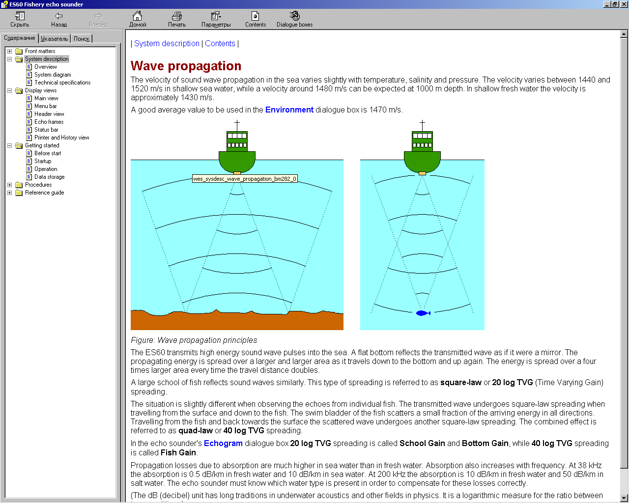
Рисунок:
Принципы распространения звуковой
волны
ES60посылает в море мощные импульсы звуковых
колебаний. Ровное дно отражает посланную
звуковую волну подобно зеркалу. Излученная
энергия распространяется на все большую
и большую площадь по мере того, как она
продвигается вниз к дну и возвращается
обратно. Энергия распространяется на
площадь в четыре раза большую каждый
раз, когда дистанция прохождения
удваивается.
Подобным образом
отражает звуковые волны большой рыбный
косяк. Такой тип распространения
называется распространением по
квадратичному закону и соответствует
закону ВАРУ 20logR.
Несколько иначе обстоит
дело при наблюдении за эхосигналами от
отдельных рыб. Излученная волна
распространяется по квадратичному
закону при прохождении от поверхности
до рыбы. Плавательный пузырь рыбы
рассеивает поступающую энергию понемногу
во всех направлениях. При обратном
прохождении от рыбы до поверхности
рассеянная волна претерпевает еще одно
распространение по квадратичному
закону. Совокупный эффект называется
распространением по закону четвертой
степени и соответствует закону ВАРУ
40logR.
В эхолотном диалоговом
окне ‘Echogram’
(Эхограмма) закон
ВАРУ 20logRназывается
‘SchoolGain’
(Усиление для Косяка) или ‘BottomGain’ (Усиление для Дна), в
то время как закон ВАРУ 40logRназывается ‘FishGain’
(Усиление для Рыбы).
Потери при распространении
вследствие поглощения значительно
больше в морской воде, чем в пресной.
Потери также увеличиваются при увеличении
частоты. При частоте 38 кГц поглощение
составляет 0,5 дБ/км в пресной воде и
10 дБ/км в морской воде. При частоте 200
кГц поглощение составляет 10 дБ/км в
пресной воде и 50 дБ/км в соленой воде.
Эхолот должен знать тип воды в текущий
момент времени, чтобы правильно
компенсировать эти потери.
(Единица измерения
децибел [дБ] является общепринятой в
гидроакустике и других областях физики.
Это логарифмическая мера измерения для
соотношения между двумя величинами).
7.2.3 Донный эхосигнал
Плоское дно с твердым
грунтом отражает излученный сигнал
подобно зеркалу. Излученный импульс
достигает всей зоны облучения дна
практически одновременно и эхосигнал,
отраженный от различных частей этой
зоны возвращается к поверхности также
практически одновременно.
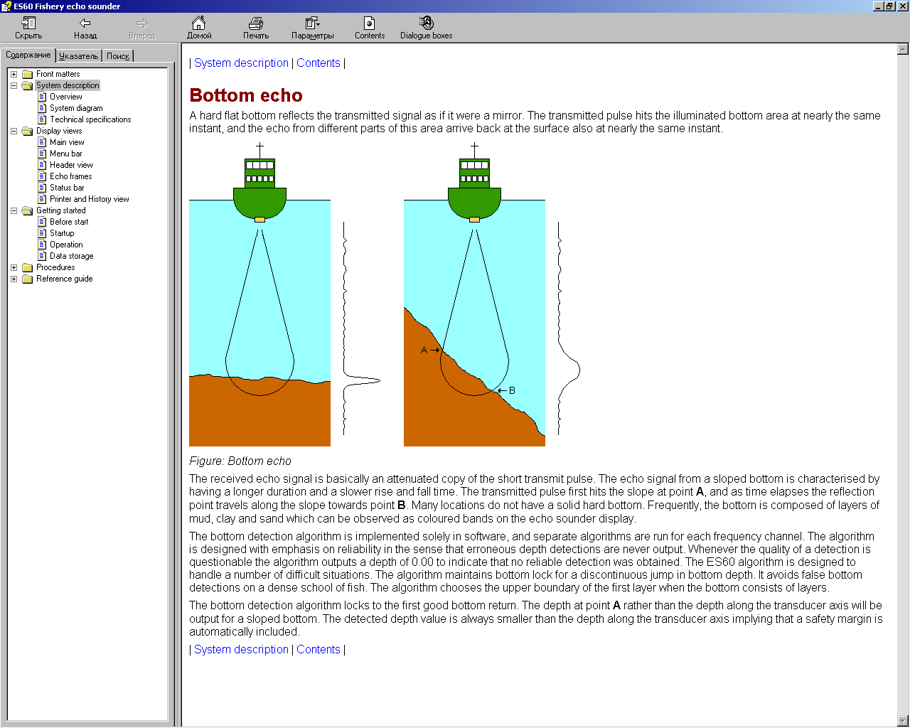
Рисунок:
Донный эхосигнал
По существу, принимаемый
эхосигнал представляет собой ослабленную
копию короткого излученного импульса.
Эхосигнал от наклонного дна характеризуется
увеличенной длительностью и более
медленными периодами нарастания и
спада. Излученный импульс сначала
соприкасается с наклонной плоскостью
в точке Аи с течением времени точка
отражения перемещается по наклонной
плоскости к точкеВ. Дно с твердым
плотным грунтом встречается редко. Чаще
всего дно представляет собой сочетание
слоев ила, глины и песка, которые можно
наблюдать в виде цветных полос на дисплее
эхолота.
Алгоритм обнаружения
дна реализован исключительно в программном
обеспечении, при этом автономные
алгоритмы выполняются в каждом частотном
канале. Алгоритм спроектирован с акцентом
на надежность в том смысле, что ошибочные
показания глубины никогда не отображаются.
Всякий раз, когда точность обнаружения
является сомнительной, алгоритм выдает
значение 0.00, означающее, что надежное
обнаружение не обеспечено. Алгоритм
эхолота ES60спроектирован для работы в сложных
ситуациях. Алгоритм обеспечивает
привязку ко дну в условиях скачкообразных
резких изменений глубины. Он исключает
ложные обнаружения дна по плотному
рыбному косяку. Алгоритм выбирает
верхнюю границу первого слоя, если дно
состоит из нескольких слоев.
Алгоритм обнаружения
дна захватывает первый большой эхосигнал
от дна. Для наклонного дна скорее будет
отображаться глубина в точке А, чем
глубина вдоль оси акустического
преобразователя. Фиксируемая глубина
всегда меньше глубины вдоль оси
акустического преобразователя, вследствие
чего автоматически увеличивается запас
надежности.
Соседние файлы в предмете [НЕСОРТИРОВАННОЕ]
- #
- #
- #
- #
- #
- #
- #
- #
- #
- #
- #
Types of Manuals:
The main types of Simrad ES60 — instructions:
- User guide — rules of useing and characteristics
- Service manual — repair, diagnostics, maintenance
- Operation manual — description of the main functions of equipment
Marine Equipment Instructions by Simrad:
-
Federal Signal Corporation G-SND
Model G-SND Sounder for Use in Hazardous LocationsLimited Warranty: This product’s limited warranty can be found at www.fedsig.com/SSG-Warranty. WARNING — Failure to follow all safety precautions and instructions may result in property damage, serious injury, or death to you or others.MESSAGES TO INSTALLERS AND USERS …
G-SND Marine Equipment, 48
-
ComAp IG-NT
Compact Controller for Stand-by and Parallel Operating Gen-sets Inteli New Technology Modular Gen-set Controller Single Parallel Island application for Asynchronous Generators IG-NT, IG-NTC, IG-NT-BB, IG-NTC-BB, IS-NT-BB, IS-NTC-BB Software version IGS-NT-Async-1.2, February 2011 USER GUIDE …
IG-NT Controller, 92
-
Stahl y04
D7418/4-UL Y04/YL4 INSTALLATION INSTRUCTIONS General Description: This application should be installed and used as recommended by the National Fire Protection Association standards and practices. The Installer should be familiar with these requirements together with any local codes or special requirements of …
y04 Marine Equipment, 2
-
Lewmar Pro Series
Pro-Series /Fish WindlassesProduct manualOwners Installations, Operation & servicing manualInstallations, Betriebs & WartungshandbuchManuel d’installation, de fonctionnement et d’entretienManual de instalación, Operación y servicioGuida all’installazione, all’uso e alla manutenzioneBruksanvisning för …
Pro Series Fishing Equipment, 27
-
Raymarine p70
p70&p70randEvolutionautopilot—overviewThisdocumentwillguideyouthroughthestepsrequiredinsetting-upandcommissioningyourEvolutionautopilotsystemusingaRaymarinep70/p70rautopilotcontrolhead.IfyouareanexistinguserofRaymarineautopilotsystems,thisdocumentwillalsohelpyoutounderstandthedifferencesbetweenthecommissioningpro …
p70 Autopilot System, 4
-
UniPOS FD7204
УниПОС – FD7204 Адресируема сиренаАДРЕСИРУЕМА СИРЕНА тип FD7204Паспорт 02-FD7204-01-20 FD7204 служи за звуково и светлинно сигнализиране в състава на адресируеми пожароизвестителни …
FD7204 Marine Equipment, 2
-
Furuno FA30
www.furuno.co.jpFA-30 VHF SPLITTERMOUNTING PROCEDURE The VHF splitter enables the AIS receiver and VHF transceiver to share a single VHF antenna.Note: The FA-30 can not receive AIS signal when the VHF transceiver is transmitting. Equipment ListsVHF Splitter: Type OP05-106, Code No. 000-011-704Mounting procedure1. Open …
FA30 Media Converter, 3

Installation manual
Simrad ES60
Fish finding echo sounder
www.SIMRAD.com
M A X I M I Z I N G Y O U R P E R F O R M A N C E A T S E A
Simrad ES60
Installation manual
This manual provides you with the basic information required to install the Simrad ES60 Fish finding echo sounder. For more detailed information about the practical use of the product, refer to the Operator manual.
304699/A September 2006

Document history
Document number: 304699 / ISBN-10: 82-8066-072-0 / ISBN-13: 978-82-8066-072-5
|
Rev. A |
September 2006 |
First version. Information is extracted from the former Instruction |
|
|
manual, and several details have been changed. |
|||
Copyright
©2006 Simrad Horten AS
The information contained in this document remains the sole property of Simrad Horten AS. No part of this document may be copied or reproduced in any form or by any means, and the information contained within it is not to be communicated to a third party, without the prior written consent of Simrad
Horten AS. The document, or any part of it, may not be translated to any other language without the written approval from Simrad Horten AS.
Disclaimer
Simrad Horten AS endeavours to ensure that all information in this document is correct and fairly stated, but does not accept liability for any errors or omissions.
Warning
The equipment to which this manual applies must only be used for the purpose for which it was designed. Improper use or maintenance may cause damage to the equipment and/or injury to personnel. The user must be familiar with the contents of the appropriate manuals before attempting to install, operate or work on the equipment.
Simrad Horten AS disclaims any responsibility for damage or injury caused by improper installation, use or maintenance of the equipment.
Support
If you require maintenance on your Simrad equipment, contact your local dealer. You can also contact Simrad using the following address: contact@simrad.com. If you need other information about this product, or any other Simrad products, visit www.simrad.com. On our web site you will also find a list of our dealers and distributors.
Simrad Horten AS
|
Strandpromenaden 50 |
Telephone: +47 33 03 40 00 |
|
|
P.O.Box 111 |
Telefax: +47 33 04 29 87 |
|
|
N-3191 Horten, |
www.simrad.com |
|
|
Norway |
simrad.sales@simrad.com |

Installation manual
|
Table of contents |
|
|
INTRODUCTION ………………………………………………………. |
9 |
|
Simplified system diagram …………………………………………………………………………. |
10 |
|
General safety rules …………………………………………………………………………………… |
11 |
|
General supply conditions ………………………………………………………………………….. |
12 |
|
Equipment responsibility………………………………………………………………….. |
12 |
|
Receipt, unpacking and storage………………………………………………………….. |
12 |
|
General installation requirements………………………………………………………………… |
13 |
|
Approval by classification society ………………………………………………………. |
13 |
|
Supply power ………………………………………………………………………………… |
13 |
|
Compass deviation………………………………………………………………………….. |
13 |
|
Noise sources ………………………………………………………………………………… |
13 |
|
Dry docking ………………………………………………………………………………….. |
13 |
|
Wiring………………………………………………………………………………………….. |
14 |
|
Equipment handling ………………………………………………………………………………….. |
15 |
|
Transportation ……………………………………………………………………………….. |
15 |
|
Lifting………………………………………………………………………………………….. |
15 |
|
Storage prior to installation or use………………………………………………………. |
16 |
|
Inspection……………………………………………………………………………………… |
17 |
|
Unpacking…………………………………………………………………………………….. |
18 |
|
General unpacking procedure………………………………………………………… |
18 |
|
Unpacking electronic and electromechanical units……………………………… |
19 |
|
Unpacking mechanical units …………………………………………………………. |
19 |
|
Unpacking transducers ………………………………………………………………… |
19 |
|
Storage after unpacking……………………………………………………………………. |
20 |
|
Storage after use …………………………………………………………………………….. |
20 |
|
Cleaning cabinets……………………………………………………………………….. |
20 |
|
Mechanical units………………………………………………………………………… |
21 |
|
Cables ……………………………………………………………………………………… |
21 |
|
Internal batteries ………………………………………………………………………… |
21 |
|
Dehumidifier …………………………………………………………………………….. |
22 |
|
Coatings …………………………………………………………………………………… |
22 |
|
Re-packaging ………………………………………………………………………………… |
22 |
|
Circuit board packaging …………………………………………………………………… |
22 |
|
Beware of ESD!…………………………………………………………………………. |
23 |
|
Unpacking and handling circuit boards ……………………………………………. |
23 |
|
Unpacking on board ……………………………………………………………………. |
23 |
|
Returning a circuit board ……………………………………………………………… |
23 |
|
Temperature protection…………………………………………………………………….. |
24 |
|
What is ESD? ………………………………………………………………………………… |
24 |

Simrad ES60
|
INSTALLATION PROCEDURES ………………………………….. |
26 |
|
Basic procedure ………………………………………………………………………………………… |
26 |
|
Configuration……………………………………………………………………………………………. |
27 |
|
Transducer ……………………………………………………………………………………. |
27 |
|
General Purpose Transceiver (GPT) ……………………………………………………. |
28 |
|
Computer ……………………………………………………………………………………… |
29 |
|
Display ………………………………………………………………………………………… |
29 |
|
Software……………………………………………………………………………………….. |
30 |
|
Printer………………………………………………………………………………………….. |
30 |
|
General Purpose Transceiver installation……………………………………………………… |
31 |
|
ES60 Marine Computer installation …………………………………………………………….. |
33 |
|
CABLE LAYOUT………………………………………………………. |
34 |
|
Cabling principles……………………………………………………………………………………… |
35 |
|
Cable identifications………………………………………………………………………… |
35 |
|
Cable information …………………………………………………………………………… |
35 |
|
System and shipyard cables ………………………………………………………………. |
35 |
|
ES60 Cable plans………………………………………………………………………………………. |
36 |
|
Cable plan with one transceiver …………………………………………………………. |
37 |
|
Cable plan with two transceivers………………………………………………………… |
38 |
|
List of cables …………………………………………………………………………………. |
39 |
|
Cable details …………………………………………………………………………………………….. |
45 |
|
Generic RS-232 Serial line cable………………………………………………………… |
47 |
|
Commercial power supply………………………………………………………………… |
48 |
|
External power supply for transceiver …………………………………………………. |
49 |
|
230 Vac power cable ……………………………………………………………………….. |
50 |
|
Ship’s ground ………………………………………………………………………………… |
51 |
|
Ethernet cable with RJ45, “straight”……………………………………………………. |
52 |
|
Ethernet cable with RJ45, “crossover”…………………………………………………. |
53 |
|
VGA/SVGA Display cable……………………………………………………………….. |
54 |
|
USB cable …………………………………………………………………………………….. |
55 |
|
PS/2 Adapter for mouse and keyboard…………………………………………………. |
56 |
|
Serial line adapter …………………………………………………………………………… |
57 |
|
GPT remote on/off ………………………………………………………………………….. |
58 |
|
GPT trigger / synchronisation ……………………………………………………………. |
59 |
|
GPT external sensors ………………………………………………………………………. |
60 |
|
GPT Event and New line ………………………………………………………………….. |
61 |
|
GPT Alarm output ………………………………………………………………………….. |
62 |
|
GPT battery…………………………………………………………………………………… |
63 |
|
Cable between ITI and echo sounder…………………………………………………… |
64 |
|
Cable between PI44/54 and echo sounder …………………………………………….. |
65 |
|
Cable between PI30/32 and echo sounder …………………………………………….. |
66 |
|
Cable between SH/SP sonar and echo sounder ………………………………………. |
67 |

Installation manual
|
Single beam, normal power transducer ………………………………………………… |
68 |
|
Single beam, high power transducer ……………………………………………………. |
69 |
|
Dual beam (wide or narrow) transducer……………………………………………….. |
70 |
|
Split beam transducer………………………………………………………………………. |
71 |
|
Split beam transducer to single beam transceiver……………………………………. |
72 |
|
Single beam transducer to split beam transceiver……………………………………. |
73 |
|
Dual frequency, single beam transducer……………………………………………….. |
74 |
|
Deep water, split beam transducer ………………………………………………………. |
75 |
|
ES38–10 transducer ………………………………………………………………………… |
76 |
|
12-16/60 transducer ………………………………………………………………………… |
77 |
|
50/200 Combi C transducer ………………………………………………………………. |
78 |
|
38/200 Combi C transducer ………………………………………………………………. |
79 |
|
Basic cable requirements……………………………………………………………………………. |
80 |
|
Cable trays ……………………………………………………………………………………. |
80 |
|
Radio Frequency interference ……………………………………………………………. |
81 |
|
Physical protection………………………………………………………………………….. |
81 |
|
Grounding…………………………………………………………………………………….. |
81 |
|
Cable connections…………………………………………………………………………… |
82 |
|
Cable terminations ………………………………………………………………………….. |
82 |
|
Cable identification …………………………………………………………………………. |
82 |
|
INTERFACES AND INTEGRATION ……………………………… |
83 |
|
About NMEA interfaces and telegrams ……………………………………………………….. |
83 |
|
NMEA …………………………………………………………………………………………. |
84 |
|
Telegrams……………………………………………………………………………………… |
84 |
|
Standard NMEA 0183 communication parameters …………………………………. |
84 |
|
Ethernet interfaces…………………………………………………………………………………….. |
84 |
|
BI500 interface………………………………………………………………………………. |
85 |
|
Transceiver interface……………………………………………………………………….. |
85 |
|
Duplex interfaces………………………………………………………………………………………. |
87 |
|
Trawl system interface …………………………………………………………………….. |
87 |
|
Catch monitoring system interface ……………………………………………………… |
88 |
|
Input interfaces …………………………………………………………………………………………. |
89 |
|
Navigation system interface………………………………………………………………. |
90 |
|
Heave sensor interface …………………………………………………………………….. |
90 |
|
Temperature sensor interface …………………………………………………………….. |
92 |
|
Output interfaces ………………………………………………………………………………………. |
92 |
|
Sonar system interface …………………………………………………………………….. |
92 |
|
Depth interface ………………………………………………………………………………. |
94 |
|
External triggering…………………………………………………………………………………….. |
95 |
|
Master system………………………………………………………………………………… |
95 |
|
Slave system………………………………………………………………………………….. |
96 |
|
GPT Auxiliary connector …………………………………………………………………………… |
96 |

Simrad ES60
|
DRAWING FILE ……………………………………………………… |
99 |
|
GPT Outline dimensions ………………………………………………………………………….. |
100 |
|
GPT Power supply outline dimensions ………………………………………………………. |
102 |
|
Marine computer outline dimensions …………………………………………………………. |
104 |
|
GPT Transducer plug connection………………………………………………………………. |
105 |
|
TECHNICAL SPECIFICATIONS ………………………………… |
106 |
|
Echo sounder specifications ……………………………………………………………………… |
106 |
|
Interface specifications …………………………………………………………………………….. |
106 |
|
General Purpose Transceiver specifications………………………………………………… |
107 |
|
Colour display specifications…………………………………………………………………….. |
108 |
|
ES60 Marine Computer specifications ……………………………………………………….. |
108 |
|
TRANSDUCER INSTALLATION ………………………………… |
110 |
|
Transducer location …………………………………………………………………………………. |
110 |
|
Go deep ………………………………………………………………………………………. |
110 |
|
Vessel heave …………………………………………………………………………………. |
111 |
|
Noise from protruding objects on the hull……………………………………………. |
111 |
|
Boundary water layer ……………………………………………………………………… |
111 |
|
Propeller noise………………………………………………………………………………. |
112 |
|
Inclination of the transducer face ………………………………………………………. |
113 |
|
Summary and general recommendation ………………………………………………. |
113 |
|
Ways of mounting the transducer ………………………………………………………………. |
114 |
|
External mounting …………………………………………………………………………. |
115 |
|
Transducer blister …………………………………………………………………………. |
120 |
|
Box keel……………………………………………………………………………………… |
126 |
|
Flush mounting in a steel tank …………………………………………………………. |
128 |
|
Acoustic window ………………………………………………………………………….. |
130 |
|
Inside the hull………………………………………………………………………………. |
132 |
|
Drop keel ……………………………………………………………………………………. |
134 |
|
Retractable transducer……………………………………………………………………. |
135 |
|
Cable glands …………………………………………………………………………………………… |
136 |
|
Order numbers……………………………………………………………………………… |
136 |
|
Cable gland for steel hulls ………………………………………………………………. |
137 |
|
Cable gland for wood or GRP hulls…………………………………………………… |
138 |
|
Cable glands for small hulls…………………………………………………………….. |
139 |
|
Cable splicing………………………………………………………………………………. |
140 |
|
Steel conduit …………………………………………………………………………………………… |
140 |
|
Handling and maintenance ……………………………………………………………………….. |
141 |
|
Approved anti-fouling paints …………………………………………………………… |
142 |
|
SIMRAD TRANSDUCERS ………………………………………… |
143 |
|
All 12 kHz transducers …………………………………………………………………………….. |
144 |
|
All 18 kHz transducers …………………………………………………………………………….. |
144 |

Installation manual
|
All 27 kHz transducers …………………………………………………………………………….. |
144 |
|
All 38 kHz transducers …………………………………………………………………………….. |
145 |
|
All 50 kHz transducers …………………………………………………………………………….. |
147 |
|
All 70 khz transducers……………………………………………………………………………… |
148 |
|
All 120 khz transducers……………………………………………………………………………. |
149 |
|
All 200 kHz transducers …………………………………………………………………………… |
150 |
|
All 710 kHz transducers …………………………………………………………………………… |
152 |

Simrad ES60
![]()
Introduction
INTRODUCTION
The purpose of this installation manual is to present the descriptions and drawings required to install the Simrad ES60 Fish finding echo sounder system. The equipment described in this manual includes the complete system with associated cabinets, but not those system units provided locally by the customer, installation shipyard or local dealer.
The manual also defines the equipment responsibility, and provides instructions for unpacking and storage.
Note
Detailed vessel specific mechanical drawings for the installation must be provided by the customer, or any shipyard contracted to perform the installation. Simrad may, on special order, provide assistance to these drawings. Drawings must be approved by the appropriate vessel certification authority prior to installation of the system.
The installation instructions given in this document must be adhered to. Failure to do so may render the guarantee void.
Topics
Simplified system diagram on page 10
General safety rules on page 11
General supply conditions on page 12
General installation requirements on page 13
Equipment handling on page 15

Simrad ES60
Simplified system diagram
A simplified system diagram is shown below.
System diagram with one transceiver
B
A
(CD010200D)
C
D
(A)= Colour monitor
(B)= Processor Unit (computer)
(C)= General Purpose Transceiver (GPT)
(D)= Transducer

Introduction
General safety rules
The Simrad ES60 Fish finding echo sounder system operates on 230 Vac 50/60 Hz.
WARNING
This voltage may be lethal!
The following safety precautions must be followed at all times during installation and maintenance work:
•Always switch off all power before installation or maintenance. Use the main circuit breaker, and label the breaker with a warning sign that informs others that
maintenance or installation work is being carried out on the system.
•Do not open the rack or cabinet doors while in rough seas. It may swing open suddenly and cause damage or injury.
•For safety reasons during troubleshooting on the equipment with power ON, two persons must always be present.
•Read and understand the first aid instructions for electric shock.
•Whenever maintenance is carried out, it is essential that a first aid kit is available, and that the maintenance personnel are familiar with the first aid instructions for electrical shock.
•The various parts of the system are heavy. Make sure that the appropriate tools and certified lifting equipment are available, and that the personnel are trained in installation and maintenance work.

Simrad ES60
General supply conditions
The following supply conditions are applicable to this Simrad ES60 Fish finding echo sounder delivery.
Equipment responsibility
The shipyard performing the installation and/or equipment dealer becomes fully responsible for the equipment upon receipt unless otherwise stated in the contract. The duration of responsibility includes:
•The period of time the equipment is stored locally before installation.
•During the entire installation process.
•While commissioning the equipment.
•The period of time between commissioning and the final acceptance of the equipment by the end user (normally the owner of the vessel which the equipment has been installed).
Unless other arrangements have been made in the contract, the ES60 Fish finding echo sounder system guarantee period (as specified in the contract) begins when the acceptance documents have been signed
Receipt, unpacking and storage
Upon accepting shipment of the equipment, the shipyard and/or the dealer should ensure that the delivery is complete and inspect each shipping container for evidence of physical damage. If this inspection reveals any indication of crushing, dropping, immersion in water or any other form of damage, the recipient should request that a representative from the company used to transport the equipment be present during unpacking.
All equipment should be inspected for physical damage, i.e. broken controls and indicators, dents, scratches etc. during unpacking. If any damage to the equipment is discovered, the recipient should notify both the transportation company
andSimrad so that Simrad can arrange for replacement or repair of the damaged equipment.
Once unpacked, the equipment must be stored in a controlled environment with an atmosphere free of corrosive agents, excessive humidity or temperature extremes. The equipment must be covered to protect it from dust and other forms of contamination when stored.
For more information, refer to Equipment handling on page 15

Introduction
General installation requirements
The following installation requirements are applicable to this Simrad ES60 Fish finding echo sounder delivery.
Approval by classification society
The ES60 Fish finding echo sounder transducer installation must be approved by Det Norske Veritas (DNV) or another classification society. The shipowner and shipyard performing the installation are responsible for obtaining installation approval.
Supply power
The supply voltage to the equipment is to be kept within ±10% of the installation’s nominal voltage. Maximum transient voltage variations on the main switchboard’s bus-bars are not to exceed -15% to +20% of the nominal voltage (except under fault conditions).
Simrad recommends that the ES60 Fish finding echo sounder is powered using an Uninterruptable Power Supply (UPS). The UPS should have the capacity to independently maintain power to the system for a minimum of 10 minutes. This ensures that the system can be switched off in a controlled manner in the event of a power failure.
Compass deviation
Once the installation is complete, the vessel must be swung with the system in both the operative and inoperative modes. The shipowner and captain are responsible for updating the deviation table accordingly with regard to the vessel’s national registry and corresponding maritime authority.
Noise sources
The vessel’s hull, rudder(s) and propeller(s) should be thoroughly inspected in dry dock prior to installation. Roughness below the water-line deformities in the shell plating and protruding obstacles can create underwater noise. These sources of turbulence must be smoothed or removed as best as possible. It is especially important that the propeller(s) is not pitted or damaged.
Dry docking
Make sure that ample clearance under the sonar trunk and/or protection blister is provided when dry docking the vessel. Avoid locating supporting blocks or structures in the vicinity of this equipment.

Simrad ES60
Note
The location of the transducer and/or protection blister must be noted on the vessel’s docking plan for future reference.
Wiring
All cables running between system cabinets located in different rooms and/or on different decks must be supported and protected along their entire lengths using conduits and/or cable trays. Note that the cables must not be installed in the vicinity of high-power supplies and cables, antenna cables or other possible sources
of interference.
Whenever possible, transducer cables must be run in steel conduits.
For more detailed information about cables and wiring, refer to
Basic cable requirements on page 80

Introduction
Equipment handling
This section provides the basic rules for transportation, storage and handling of units. In this context, a unit may be any large or small part of the system. It can be supplied as part of the initial delivery, or as a spare part.
Transportation
Unless otherwise stated in the accompanying documentation, electronic, electro-mechanical and mechanical units supplied by Simrad can be transported using all methods approved for delicate equipment; (by road, rail, air or sea). The units are to be
transported in accordance with general or specific instructions for the appropriate unit(s), using pallets, transport cases, or carton boxes as appropriate.
Note
Special local restrictions concerning air transportation may be applied to units containing certain types of batteries. These units must be checked properly, and the regulations must be investigated by the packer/shipper before the unit is dispatched.
All local transportation must be carried out according to the same specifications as for the initial delivery. In general, all units must be handled with care.
The carton or case containing the unit must be kept dry at all times, and must be sheltered from the weather. It must not be subjected to shocks, excessive vibration or other rough
handling. The carton or case will normally be marked with text or symbols indicating which way it is to be placed. Follow any instructions given, and ensure the case is always placed with its “top” uppermost.
The carton or case must not be used for any purpose for which it was not intended (step, table, etc.), and in the absence of other information, no other cartons or cases must be stacked on top of it.
Lifting
A heavy crate will normally be marked with its weight, and the weights of other cartons or crates will normally be entered on the packing list.
•You must always check the weight of a crate before you attempt to lift it.
•You must always use lifting apparatus that is approved and certified for the load.

Simrad ES60
Heavy units may be equipped with lifting lugs for transportation by crane within the workshop or installation area. Before you use a crane:
•You must check the applicable weight certificate for the crane.
•You must check the security of the lifting lugs.
Ensure that all available lifting lugs are used. Ensure the unit remains under control during the operation to avoid damage to the unit, equipment or personnel.
Heavy units may be transported using a forklift truck. Special attention must then be paid to the position of the unit’s centre of gravity. The units must be properly secured to the truck.
Storage prior to installation or use
When a system, a unit or a spare part has been delivered to the customer, it may be subject to long time storage prior to installation and use. During this storage period, certain
specifications must be met. The equipment must be preserved and stored in such a way that it does not constitute any danger to health, environment or personal injury.
1The equipment must be stored in its original transportation crate.
2Ensure that the units are clearly separated in the shelves and that each unit is easily identifiable.
3The crate must not be used for any purpose for which it was not intended (eg. work platform etc.).
4The crates must not be placed on top of each other, unless specific markings permit this.
5The crates must not be placed directly on a dirt-floor.
6Do not open the crate for inspection unless special circumstances permit so.
•“Special circumstances” may be suspected damage to the crate and its content, or inspections by civil authorities.
•If any units are damaged, prepare an inspection report stating the condition of the unit and actions taken. Describe the damage and collect photographic evidence if possible. Re-preserve the equipment.
•If the units are not damaged, check the humidity absorbing material. If required, dry or replace the bags, then re-pack the unit(s) according to the packing instructions.
7If the crate has been opened, make sure that is it closed and sealed after the inspection. Use the original packing material as far as possible.

Introduction
8The storage room/area must be dry, with a non-condensing atmosphere. It must be free from corrosive agents.
9The storage area’s mean temperature must not be lower than -30° C, and not warmer than +70° C. If other limitations apply, the crates will be marked accordingly.
Note
Transducers must not be stored in temperatures below -20° C, or higher than +60° C.
10The crate must not be exposed to moisture from fluid leakages.
11The crate must not be exposed to direct sunlight or excessive warmth from heaters.
12The crate must not be subjected to excessive shock and vibration.
13If the unit contains normal batteries, these may have been disconnected/isolated before the unit was packed. These must only be reconnected before the installation starts. Units containing batteries are marked.
Caution
Units containing lithium or alkaline batteries must be handled separately and with care. Such units are marked accordingly. Do not attempt to recharge such batteries, open them or dispose of them by incineration. Refer to the applicable product data sheets.
Inspection
An inspection must be carried out immediately after the unit(s) have arrived at their destination.
1Check all wooden or cardboard boxes, plastic bags and pallets for physical damage. Look for signs of dropping, immersion in water or other mishandling.
2If damage is detected externally, you will have to open the packaging to check the contents. Request a representative of the carrier to be present while the carton is opened, so any transportation damage can be identified.
3If any units are damaged, prepare an inspection report stating the condition of the unit and actions taken. Describe the damage and collect photographic evidence if possible. Send the inspection report to Simrad as soon as possible.

Simrad ES60
4If the units are not damaged, check the humidity absorbing material. If required, dry or replace the bags, then re-pack the unit(s) according to the packing instructions.
Unpacking
General unpacking procedure
Normal precautions for the handling, transportation and storage of fragile electronic equipment must be undertaken.
Note
If the unit is not to be prepared for immediate use, you may consider storing it unopened in its original packing material. However, it may be useful to open the case to check its contents for damage and retrieve any accompanying documentation.
Do not use a knife to open cardboard cartons — the contents may lie close to the surface, and may be damaged by the blade.
1Check the carton before opening it to ensure it shows no signs of dropping, immersion in water or other mishandling. If the carton shows signs of such damage, refer to the paragraph covering Inspection on receipt.
2Place the carton on a stable work bench or on the floor with the top of the carton uppermost.
3In the absence of other instructions, always open the top of the carton first. The contents will normally have been lowered into the carton from above, so this will usually be the easiest route to follow. Care must be used when opening the carton to ensure the contents are not damaged. Do not use a knife to open cardboard cartons
4If the carton has been closed using staples, remove the staples from the carton as you open it. This will reduce the possibilities of scratch injury to yourself and damage to the contents.
5If a wooden crate has been closed using screws, always remove them using a screwdriver. Do not attempt to prise the lid off with a crowbar or similar.
6Once the carton is open, carefully remove all loose packing and insulation material. Check for manuals and other documents that may have been added to the carton during packing, and put these to one side. Check also for special tools, door keys etc.
![]()
Introduction
Unpacking electronic and electromechanical units
Electronic and electromechanical units will normally be wrapped in a clear plastic bag. Lift the unit, in its bag, out of the carton and place it in a stable position on the floor/work bench.
Inspect the unit for damage before opening the plastic bag.
Note
Beware of the dangers of Electro-Static Discharge (ESD) both to yourself and to the equipment, when handling electronic units and components.
Cables must never be used as carrying handles or lifting points.
Do not break the seal to open a circuit board package before the board is to be used. If the board package is returned to the manufacturer with the seal broken, the contents will be assumed to have been used and the customer will be billed accordingly.
Assuming all is well, open the bag and remove the unit.
Open the unit and check inside. Remove any packing and desiccant material that may be inside.
Unpacking mechanical units
Mechanical units may be heavy. Using a suitably certified lifting apparatus, lift the unit out of the crate and place it in a stable position on the floor/work bench.
Inspect the unit for damage and remove any packing material that may be inside the unit.
Unpacking transducers
Transducers may be supplied mounted to a hull unit (if any), or packed separately. Crates are normally identified by the order number and the serial number.
The transducer face must be protected by a rigid, padded cover (e.g. a wooden box lined with foam rubber) all the time it is exposed to the risk of physical damage.
Caution
Once transducer is unpacked, great care must be taken to ensure that transducer body and cabling is not exposed to any mechanical stress.

Simrad ES60
Storage after unpacking
The unit must whenever possible be stored in its original transportation crate until ready for installation. The crate must not be used for any purpose for which it was not intended (eg. work platform etc.).
Once unpacked, the equipment must be kept in a dry, non condensing atmosphere, free from corrosive agents and isolated from sources of vibration.
Note
Do not break the seal to open a circuit board package before the board is to be used. If the board package is returned to the manufacturers with the seal broken, the contents will be assumed to have been used and the customer will be billed accordingly.
The unit must be installed in its intended operating position as soon as possible after unpacking. If the unit contains normal batteries, these may have been disconnected/isolated before the unit was packed. These must then be reconnected during the installation procedure. Units containing batteries are marked.
Note
Units containing lithium or alkaline batteries must be handled separately and with care. Such units are marked accordingly. Do not attempt to recharge such batteries, open them or dispose of them by incineration. Refer to the applicable product data sheets.
Storage after use
If a unit is removed from its operating location and placed into storage, it must be properly cleaned and prepared before packing.
Cleaning cabinets
If a cabinet has been exposed to salt atmosphere while it was in use, it must be thoroughly cleaned both internally and externally to prevent corrosion.
1Wipe the cabinet externally using a damp cloth and a little detergent. Do not use excessive amounts of water as the unit may not be water tight. On completion, dry the unit thoroughly.
2All surfaces must be inspected for signs of corrosion, flaking/bubbling paint, stains etc. Damaged or suspect areas must be cleaned, prepared and preserved using the correct preservation mediums for the unit. The mediums to be used will usually be defined in the units’ maintenance manual.

Introduction
3Open the unit, and using a vacuum cleaner, remove all dust etc. from the unit. Great care must be taken to ensure the circuit boards and modules are not damaged in the process.
Mechanical units
If a mechanical unit may has been exposed to a salt atmosphere while it was in use, it must be thoroughly cleaned both internally and externally to prevent corrosion.
1If the construction materials and type of unit permits, wash the unit using a high-pressure hose and copious amounts of fresh water. Examples are the lower parts of hull units (outside the hull) or subsea units
2Ensure that all traces of mud and marine growth are removed. Use a wooden or plastic scraper to remove persistent growth, barnacles etc. On completion, dry the unit thoroughly.
Caution
Do not use a high pressure hose in the vicinity of cables or transducers. Do not use sharp or metal tools on a transducer face.
3If the materials or type of unit prevents the use of a high-pressure hose, wipe the unit using a cloth dampened with water containing a little detergent. Examples are the upper parts of hull units (inside the hull) and hydraulic systems
4Do not use excessive amounts of water as some components on the unit may not be water tight. Wipe off the detergent with a damp cloth, then dry the unit thoroughly.
5All surfaces must be inspected for signs of corrosion, flaking/bubbling paint, stains etc. Damaged or suspect areas must be cleaned, prepared and preserved using the correct preservation mediums. The mediums to be used will normally be defined in the unit’s maintenance manual.
Cables
Wipe clean all exposed cables, and check for damage. If a cable shows signs of wear or ageing, contact Simrad for advice.
Internal batteries
If the unit contains batteries, these may discharge slowly during storage. If the unit is to be stored for an extended period, disconnect or remove all internal batteries.

Simrad ES60
A suitable piece of insulating material can be placed between the battery and the electrical contacts to prevent electrical discharge. The battery can then remain in the unit, reducing the risk of it being misplaced during the storage period.
Caution
Units containing lithium or alkaline batteries must be handled separately and with care. Such units are marked accordingly. Do not attempt to recharge such batteries, open them or dispose of them by incineration. Refer to the applicable product data sheets.
Dehumidifier
Place a suitably sized bag of desiccant material (silica gel or similar) into the unit to keep the electronic components as dry as possible.
Coatings
Spray the unit externally with a corrosion inhibitor (e.g. a light oil) before packing.
Re-packaging
Whenever possible, the unit must be stored and transported in its original packing material and/or crate. In the event that this material is not available, proceed as follows:
•Small units must be protected from damp by being placed within a plastic bag at least 0.15 mm thick. An appropriate quantity of desiccant material should be placed inside this bag, and the bag sealed. The sealed unit must then be placed in an appropriate carton or crate, and supported in the container by appropriate shock-absorbing insulation (polystyrene foam chips etc.).
•Large units must be placed in a suitable cardboard box or wooden crate. The unit must be protected against physical damage by means of shock-absorbing insulation mats. The box must be clearly marked with its contents, and must be stored in a dry and dust-free area.
Circuit board packaging
Circuit boards are delicate items. They may work year after year in an advanced product, but then fail due to a small spark of static electricity. For this reason, it is very important that they are properly handled and protected during shipping.

Introduction
Beware of ESD!
When you handle electronic circuit boards, you must beware of the dangers of electrostatic discharge (ESD), both to yourself and to the equipment. In order to ensure safe transport and storage, circuit boards and other electronic units will always be wrapped in a clear plastic protective bag, and the bag will be sealed.
See also: What is ESD? on page 24.
Unpacking and handling circuit boards
To unpack a circuit board:
•Wherever possible, prepare a suitable workbench. It must have an approved conductive service mat, and it must be connected directly to a reliable earth point via its earthing cord. You must wear a wristband in direct contact with the skin, and the wristband must be connected to the service mat.
•Lift the circuit board, in its protective bag, out of the carton and place it in a stable position on the a floor/work bench.
•Inspect the unit for damage before you open the plastic bag.
•Do not break the seal to open a circuit board package before the board shall to be used. If the board package is returned with the seal broken, we will assume that the content has been used, and we will bill you accordingly.
•Assuming all is well, open the bag and remove the unit.
•Take out and keep the documentation. You will need it if the circuit board shall be returned to us. Also, remove any packing and desiccant material that may be inside.
•Keep the protective plastic bag for future use.
Unpacking on board
When you are working on board a vessel, an “approved conductive service mat” is often far away. As you still need to unpack circuit boards, make sure that you do it in the instrument room, or at another location where you have a steel deck. Keep far away from the bridge or any other rooms with wall-to-wall carpets! If possible, bring a wristband and ground yourself.
Returning a circuit board
If you wish to return a circuit board to us, observe the following rules.
•Place the circuit board to be returned in the same protective plastic bag as you originally received it in — or a protective bag of similar ESD protection quality.
•DO NOT use standard plastic bags, such as commercial bubble wrap.

Simrad ES60
•Fill in all the necessary information on the applicable documentation and place it inside the bag.
•Seal the bag.
•Place the circuit board in a suitable carton, and secure it for shipping.
Note
Failure to follow these rules may result in unserviceable circuit boards.
Temperature protection
If the unit must be protected against extremes of temperature, the carton/crate must be lined on all walls, base and lid with 5 cm thick polyurethane or polystyrene foam. These units will be identified as delicate in the applicable documentation.
The package must then be clearly marked:
Must not be transported or stored in temperatures below -5 degrees Celsius.
Other units can normally be stored in temperatures between -30° C and +70° C, refer to the system’s technical specifications for details.
Transducers must not be stored in temperatures below -20° C and above +60° C.
What is ESD?
Electro-Static Discharge (ESD) is the transfer of an electrostatic charge between two bodies at different electrostatic levels, caused either by direct contact or induction by an electrostatic field. The passing of a charge through an electronic device can cause localised overheating, and it can also “puncture” insulating layers within the structure of the device. This may deposit a conductive residue of the vaporised metal on the device, and thus create a short circuit. This may result in a catastrophic failure, or degraded performance of the device.
ESD protection
Sensitive electronic circuit boards must be transported and stored in protective packing bags. The circuit boards must not be transported or stored close to strong electrostatic, electro-magnetic or radioactive fields. If it is necessary to open and touch the circuit board inside the protective bag, then the following precautions must be taken:

Introduction
•The working area must be covered by an approved conductive service mat that has a resistance of between 50 kΩ and 2 MΩ, and is connected directly to a reliable earth point via
its earthing cord.
•The service personnel involved must wear a wristband in direct contact with the skin, connected to the service mat.
•Printed circuit boards must be placed on the conductive service mat during installation, maintenance etc.
•If, for any reason, it is necessary to move the circuit board from the conductive service mat, it must be placed in an approved antistatic transportation container (e.g. static shielding bag) before transportation.
•During installation and servicing, all electrical equipment (soldering irons, test equipment etc.) must be earthed.

Simrad ES60
INSTALLATION PROCEDURES
This chapter provides the basic information required to install the physical units.
Note
Physical installation of commercial units (computers, printers, displays) is not described in this manual. Refer to the applicable user manual(s) provided with the product.
Topics
Basic procedure on page 26
Configuration on page 27
General Purpose Transceiver installation on page 31
ES60 Marine Computer installation on page 33
Basic procedure
This is the basic installation procedure.
1Check that you have received all parts required for the installation; cables, connectors, brackets etc.
2Install the transducer(s) and the transducer cables according to the guidelines in this manual and the drawings provided with the transducer.
3If applicable, install the two-wire cable for the temperature sensing thermistor.
4Mount the Processor Unit (computer) and the display using the appropriate brackets.
5Connect the computer and display cables:
•Power cable to display monitor.
•Power cable to computer.
•Video cable from computer to display monitor.
•Connect the pointing device (mouse or trackball)
6Mount the General Purpose Transceiver using the appropriate brackets.
7Connect the cables:
•Transducer cable(s)
•Power cable(s)
•If applicable, connect the cable from the temperature sensor.
•If available, install a two-wire cable for remote on/off of the General Purpose Transceiver(s).

Installation procedures
8Prepare and install the ethernet cable(s) between the General Purpose Transceiver(s) and the computer:
•An Ethernet cable must be used between the General Purpose Transceiver and the computer.
•If only one General Purpose Transceiver is used, you need a twisted pair cable with swapped receive and transmit wires. The cable is connected between the transceiver and the computer.
•An Ethernet switch is required if your system includes more than one General Purpose Transceiver. If a hub is used, all ethernet cables must be of the “straight through” type.
9Prepare and install the required serial line interfaces.
•Connect navigation receiver, trawl system and heave sensor with serial line output to the rear of the echo sounder computer using RS-232 cables. Heave sensors with an analog output are connected directly to the Auxiliary connector of the nearest transceiver.
10If required, prepare and install the synchronization cable(s).
•Synchronous transmission is desirable if there are
several echo sounders on-board the vessel. For every echo sounder and every transceiver on-board the ship, connect the appropriate pins at the Auxiliary connectors together using a two-wire cable.
Configuration
The Simrad ES60 Fish finding echo sounder is designed as a modular system. It supports a variety of configurations and frequency options. The delivery may consist of:
•Transducer(s)
•General Purpose Transceiver(s) (GPT)
•Ethernet switch (if the system comprises more than one GPT)
•Processing Unit (computer)
•Display monitor
•Pointing device (mouse or trackball)
The computer, display monitor and pointing device may be provided locally using standard commercial components.
Transducer
One or more transducers are included. A single frequency General Purpose Transceiver will accept one transducer, while a dual frequency transceiver will accept two transducers.

Simrad ES60
A large number of transducers are available. There are several transducer alternatives for each operating frequency with different beam widths, power rating and mounting arrangements. All transducers are rated 60 or 75 ohms. Each has an efficiency of approximately 50%.
Related topics
Simrad transducers on page 143
Transducer Installation on page 110
General Purpose Transceiver (GPT)
One or more General Purpose Transceivers (GPT) are included.
A single frequency General Purpose Transceiver accepts one transducer, while a dual frequency transceiver accepts two transducers.
The General Purpose Transceiver is a small self-contained unit containing its own power supply. It operates on +12 Vdc or 115-230 Vac. The unit can be mounted anywhere on board the ship, provided that the location is dry and ventilated We recommend that it is mounted as close to the transducer(s) as possible. Power cable and mounting brackets are enclosed.
An Ethernet link connects the General Purpose Transceiver to the Processor Unit (computer). This link may comprise a
standard Ethernet cable and — if necessary — an Ethernet switch. The transceiver includes its own Ethernet interface. A network interface board must be fitted to the computer.
The General Purpose Transceiver is available in single beam and split beam configurations. A dual frequency single beam configuration is also provided. The possible operating frequencies are listed in the technical specifications. Typical configurations include:
•GPT-S38(4)-F (single beam 38 kHz, 4 kW)
•GPT-S50(4)-F (single beam 50 kHz, 4 kW)
•GPT-S70(1)-F (single beam 70 kHz, 1 kW)
•GPT-S120(1)-F (single beam 120 kHz, 1 kW)
•GPT-S200(1)-F (single beam 200 kHz, 1 kW)
•GPT-Q38(4)-F (quad (split) beam 38 kHz, 4 kW)
•GPT-Q120(4)-F (quad (split) beam 120 kHz, 4 kW)
•GPT-S38(1)/S50(1)-F (single beam 38 and 50 kHz, 1+1 kW)
Two or more General Purpose Transceivers can exist on the same Ethernet cable. A multi-frequency sounder emerges simply by using several transceivers on the Ethernet cable.
![]()
Installation procedures
•Example: A dual frequency split-beam sounder emerges by connecting two split-beam transceivers to the Ethernet cable.
•Example: A triple frequency single-beam sounder emerges by connecting three single-beam transceivers to the Ethernet cable.
Related topics
General Purpose Transceiver installation on page 31 General Purpose Transceiver specifications on page 107
Computer
The ES60 Processor Unit is a commercial computer, and it may be purchased locally. However, the ES60 Marine Computer can be provided, and we recommend this computer for maritime use, as it contains no moving parts. Microsoft© Windows© operating system is used. Power supply, a pointing device (mouse) and the necessary brackets for physical mounting are enclosed. The computer operates from 115 Vac or 230 Vac.
If you purchase a computer locally, it is important to ensure that the chosen model meets the functional requirements. Also, make sure that the computer design and construction allows for marine use and safe installation. A lap-top computer may also be used as long as it meets the functional requirements.
Minimum computer specifications
•Operating system: Microsoft© Windows© XP
•Processor speed: 1 Gb
•Memory: 512 Mb
•Free hard disk space: 1 Gb
•Interfaces:
–One ethernet interface
–One or more RS-232 serial line interfaces (depends on how many interfaces that are required for the specific integration)
•Display resolution: 1024 x 768
Related topics
ES60 Marine Computer installation on page 33 ES60 Marine Computer specifications on page 108
Display
A colour LCD monitor can be provided with the echo sounder system. Any commercial display can also be used, but it must be able to operate with a resolution 1280×1024.

Simrad ES60
Related topics
Colour display specifications on page 108
Software
All echo sounder configurations run identical software. The software automatically adapts to the number and type of installed transceivers during power-on. Upon delivery, the software is installed on the computer, as well as supplied on a CD-ROM. Software updates are distributed on a CD-ROM.
Printer
A printer can be supplied, or purchased locally. Most standard off-the-shelf colour printers can be used. A standard Windows driver is required, this is normally supplied with the printer.

Installation procedures
General Purpose Transceiver installation
The General Purpose Transceiver (GPT) is a self-contained unit. It can be mounted anywhere on board the vessel. It is however recommended to mount the GPT as close to the transducer(s) as possible in order to minimize the electrical interference in the transducer cable.
The GPT is easily mounted with the brackets supplied with the unit.
Preparations
Two brackets and four pan head screws are enclosed. The side walls of the unit each hold six screws; three screws along the bottom edge and three screws along the top edge. The brackets can be vertically mounted in three different positions;
•Use the two rear holes, or
•Use the two centre holes, or
•Use the two front holes.
The brackets can be horizontally mounted in four different ways using either the bottom edge holes or the top edge holes.
The brackets can be horizontally mounted in four different ways using either the bottom edge holes or the top edge holes.
Procedure
1Unscrew two screws from each side wall.
2Mount the brackets using the pan head screws.
3Position the unit on the surface and mark the four mounting holes.
4Remove the unit, and drill mounting holes.

Simrad ES60
5Mount the General Purpose Transceiver (GPT) using the appropriate brackets.
6Mount the unit to the surface using 5 mm bolts.
External power supply
In order to avoid electrical noise, certain GPT configurations are supplied with an external power supply. This supply is mounted by means of two brackets. Observe the outline dimension drawing.
Related topics
GPT Outline dimensions on page 100
GPT Power supply outline dimensions on page 102 General Purpose Transceiver specifications on page 107

Installation procedures
ES60 Marine Computer installation
The ES60 Marine Computer is an industrial computer. It is small, rugged, and contains no moving parts. This means that fans, hard disks and CD drives are omitted. The computer provides two ethernet sockets, four RS-232 serial lines and several USB connectors. The hard disk is replaced with a commercial 4 Gb flash disk.
The ES60 Marine Computer is easily mounted with the brackets supplied with the unit. A small external power supply is provided, and must be placed near the computer.
Preparations
Two brackets and eight bolts enclosed. Mount the two brackets at the bottom of the computer.
Procedure
1Locate the most convenient location for the computer. Make sure that you can access both the rear and front side of the computer after it has been installed. In order to allow for future maintenance, mount the computer with its rear panel available for immediate access.
2Observe the outline dimension drawing. Mark the location of the six holes provided on the two brackets.
3Mount the unit using six bolts or screws.
4When you install the cabling, make sure that the various adapter and cables are secured, and able to withstand vibration and the movements of the vessel.
Related topics
ES60 Marine Computer specifications on page 108

Simrad ES60
CABLE LAYOUT
This chapter describes the installation requirements for the Simrad ES60 Fish finding echo sounder cables. These
instructions must be used together with the applicable cable plan.
Note
All electronic installations and corresponding wiring must be in accordance with the vessel’s national registry and corresponding maritime authority and/or classification society.
If no such guidelines exist, we recommend that Det Norske Veritas (DNV) Report No. 80-P008 «Guidelines for Installation and Proposal for Test of Equipment» be used as a guide.
Topics
Cabling principles on page 35
ES60 Cable plans on page 36
Basic cable requirements on page 80
Related topics
Interfaces and integration on page 83

Cable layout
Cabling principles
Cable identifications
On the cable layout drawing and in the corresponding cable list(s), all cables are identified with individual cable numbers. Unless otherwise defined, each cable is identified with a Cxx number, where xx is an integer.
References are made to dedicated cable drawings. If required, the shipyard or owner may also identify the cables according to their own system. Unless otherwise specified, the ES60 documentation will however only refer to the identification numbers provided by Simrad.
Cable information
A drawing with additional specifications for each cable is provided. Each cable drawing may, when applicable, include:
•Required minimum specifications
•Connections at each end (including reference to the corresponding: system unit, terminal board identification and plug/socket to be used)
•Corresponding terminations
•Number of cores
System and shipyard cables
Cables fall into two categories.
•System cables: These cables are supplied by Simrad with the ES60 system delivery.
•Shipyard cables: These cables must be provided by the shipyard performing the installation, or the shipowner.
Note
Simrad accepts no responsibility for damage to the system or reduced operational performance caused by improper wiring.

Simrad ES60
ES60 Cable plans
Due to its modular design, the Simrad ES60 Fish finding echo sounder can be set up in a variety of configurations to suit individual needs for operational frequencies, split beam or single beam transducers and operational facilities. It is not practical to define specific cable plans for all these configurations.
To illustrate the cabling, the following basic cable plans are provided:
•Standard setup with one computer and one General Purpose Transceiver.
•Standard setup with one computer and more than one General Purpose Transceiver.
Note
The Simrad ES60 Fish finding echo sounder can be set up to work with maximum four -4- operational frequencies. This means that you can use four single frequency transceivers (single or split beam), two dual frequency transceivers, or any combinations
of these.
Legend:
(A)= Display
(B)= Computer (The ES60 Marine Computer may be supplied)
(C)= General Purpose Transceiver (GPT)
(D)= Junction box for transducer cable (optional)
(E) = Transducer
(F) = Ethernet switch (required when more than one transceiver is used)
Topics
Cable plan with one transceiver on page 37
Cable plan with two transceivers on page 38
List of cables on page 39

Cable layout
Cable plan with one transceiver
1
|
ES60/C9 |
A |
|
|
ES60/C6 |
||
|
ES60/C3 |
ES60/C5 |
|
|
ES60/C1 |
B |
ES60/C19 |
|
ES60/C18 |
||
|
ES60/C4 |
||
|
ES60/C7A-n |
||
|
ES60/C2 |
ES60/C8A-n |
|
|
ES60/C14 |
ES60/C12 |
ES60/C10 |
|
ES60/C11 |
||
|
ES60/C19 |
||
|
ES60/C20 |
||
|
ES60/C13 |
||
|
C |
||
|
ES60/C16 |
|
ES60/C15 |
|
|
SIMRAD |
GPT |
|
ES60/C17 |
|
|
D |
E

Simrad ES60
Cable plan with two transceivers
1
|
ES60/C2 |
|
|
ES60/C14 |
ES60/C12 |
|
(CD10212F) |
|
|
2 |
F
C
ES60/C19
ES60/C18
ES60/C4
ES60/C7A-n
ES60/C8A-n
ES60/C22
ES60/C10
ES60/C11
ES60/C19
ES60/C20
C
ES60/C13
ES60/C16
ES60/C13
ES60/C16
|
ES60/C15 |
D |
ES60/C15 |
D |
|
ES60/C17 |
ES60/C17 |
||
|
E |
E |
![]()
Cable layout
List of cables
ES60/C01 — Keyboard
This is a standard keyboard cable, and it is usually fixed to the keyboard. A keyboard is not provided with the Simrad ES60 Fish finding echo sounder system. If you wish to connect a keyboard, you must provide it yourself. The connection depends on the make and model of the computer. PS/2 and USB plugs are the most common types.
The ES60 Marine Computer is provided with a single PS/2 connector to allow for both keyboard and mouse connection. If you wish to use only a mouse, it can be connected directly to this input. If you wish to use both a keyboard and a mouse, a special adapter is provided with the computer. Both the keyboard and the mouse must be equipped with a PS/2 connector. The ES60 Marine Computer is however also equipped with several USB sockets. The most convenient method would normally be to use these for both keyboard and mouse connections.
Adapter: PS/2 Adapter for mouse and keyboard on page 56.
ES60/C02 — Mouse (or other pointing device)
This is a standard mouse cable, and it is usually fixed to the mouse. A standard mouse or trackball device is provided with the echo sounder if you order a computer from Simrad.
ES60/C03 — Display
This is a standard display cable, and it is usually provided with the display. Note that several video formats are available. The VGA/SVGA format using a 15–pin D-sub connector is still the most common, but other formats have also been introduced.
Which cable to use depends on the display you use and the video outputs provided by your computer.
Cable details: VGA/SVGA Display cable on page 54.
Note
You must never disconnect or plug in the display cable while power is applied to the computer!
ES60/C04 — Printer
A printer can be connected to the computer. A cable for this is normally provided with the printer. The most common interface formats are parallel (Centronics) and USB.
Cable details: USB cable on page 55.

Simrad ES60
ES60/C05 — AC power to computer
This normally a standard power cable, and it is provided with the computer. Ensure that the computer is set up to match the AC voltage you have available. Most computers will however operate on 115 Vac, 230 Vac or both.
The ES60 Marine Computer is provided with a separate power supply.
Cable details: 230 Vac power cable on page 50.
ES60/C06 — AC power to the display
This normally a standard power cable, and it is provided with the display. Ensure that the display is set up to match the AC voltage you have available. Most displays will however operate on 115 Vac, 230 Vac or both.
Cable details: 230 Vac power cable on page 50.
Note that some older display types may be fitted with a separate power supply.
ES60/C07 — Serial interface lines (RS-232)
Serial interfaces are used to connect the ES60 Fish finding echo sounder to other fish finding or navigation systems. All serial interface cables must be provided by the installation shipyard. If more than one serial cable is used, add the characters “A”, “B” to “n” to the cable identifier.
Cable details:
•Generic RS-232 Serial line cable on page 47
•Cable between ITI and echo sounder on page 64
•Cable between PI44/54 and echo sounder on page 65
•Cable between PI30/32 and echo sounder on page 66
•Cable between SH/SP sonar and echo sounder on page 67 Additional information:
•About NMEA interfaces and telegrams on page 83
•Trawl system interface on page 87
•Catch monitoring system interface on page 88
•Navigation system interface on page 90
•Heave sensor interface on page 90
•Sonar system interface on page 92
•Depth interface on page 94

Cable layout
The number of serial line interfaces depends on your computer make and model. For a typical integration of the ES60 Fish finding echo sounder, we recommend that minimum three serial lines are available. If your computer can not support this, commercial RS-232/USB converters are available.
The ES60 Marine Computer is provided with an adapter. This adapter allows you to connect four serial lines to the large interface socket on the rear panel of the computer.
Adapter: Serial line adapter on page 57.
ES60/C08 — Universal Serial Bus (USB)
Most computers support one or more USB connectors for peripheral devices. In a typical ES60 configuration, the USB connectors are not used. However, a USB interface may be used to accept serial line information (providing a converter is used). You can also use the USB interfaces to connect a mouse, keyboard, printer or memory devices.
The number of USB sockets available depends on your computer make and model. If more than one USB interface is used, add the characters “A”, “B” to “n” to the cable identifier.
Cable details: USB cable on page 55.
ES60/C09 — Ground
This cable is used to connect the display to ship’s ground. The cable must be supplied by the installation shipyard.
Cable details: Ship’s ground on page 51.
ES60/C10 — External synchronisation
This cable is used to connect the General Purpose Transceiver (GPT) to an external system in order to provide transmission control (synchronisation). This is a very useful feature if you have other hydroacoustic systems on board, and these transmit and receive on the same frequency (or harmonics of this frequency) as the ES60 system. The cable(s) must be supplied by the installation shipyard.
Note
If more than one General Purpose Transceiver (GPT) is used by the echo sounder system, the synchronization signal TrigIn must be connected to all of them.
Cable details: GPT trigger / synchronisation on page 59. Additional information:
•External triggering on page 95
•GPT Auxiliary connector on page 96

Simrad ES60
ES60/C11 — External motion and temperature sensors
The General Purpose Transceiver (GPT) will accept information from external motion and temperature sensors. The cable(s) must be supplied by the installation shipyard. If more than one General Purpose Transceiver (GPT) is used by the echo sounder system, the motion and temperature sensors are connected to only one of them.
Cable details: GPT external sensors on page 60. Additional information:
•Heave sensor interface on page 90
•Temperature sensor interface on page 92
•GPT Auxiliary connector on page 96
ES60/C12 — Remote on/off
The General Purpose Transceiver (GPT) allows you to design a simple box with a separate on/off switch for the transceiver. An on/off switch will prevent the transceiver from being powered up constantly. Some displays provide this functionality by means of a “Remote” connector on the rear side. The cable must be supplied by the installation shipyard. If more than one General Purpose Transceiver (GPT) is used by the echo sounder system, we recommend that you install one separate on/off switch for each unit.
Note
Do not use the spare wires in the ethernet cable to provide the remote control facility!
Cable details: GPT remote on/off on page 58.
Additional information: GPT Auxiliary connector on page 96
ES60/C13 — GPT battery supply
The General Purpose Transceiver Unit (GPT) can be powered from a DC supply. The power cable must be provided by the installation shipyard.
Cable details: GPT battery on page 63.
ES60/C14 — Ethernet cable between computer and transceiver
In a standard echo sounder configuration with only one General Purpose Transceiver, you must use a “crossover” ethernet cable between the computer and the transceiver. The ethernet cable must be provided by the installation shipyard.

Cable layout
If an Ethernet switch is used between the computer and the transceiver, “straight” cables must be used on either side of the switch.
Cable details:
•Ethernet cable with RJ45, “crossover” on page 53
•Ethernet cable with RJ45, “straight” on page 52
ES60/C15 — Ground
This cable is used to connect the General Purpose Transceiver Unit (GPT) to ship’s ground. The cable must be supplied by the installation shipyard.
Cable details: Ship’s ground on page 51.
ES60/C16 — AC power to the General Purpose Transceiver Unit (GPT)
This normally a standard power cable, and it is provided with the General Purpose Transceiver Unit (GPT).
Due to unfortunate properties of the commercial built-in power supply, certain transceiver configurations operating on 230 Vac will be supplied with a separate power supply. When this supply is used, the 230 Vac power cable is not used. The external power supply is connected to the battery inputs on the transceiver.
Cable details: 230 Vac power cable on page 50.
Further details: External power supply for transceiver on page 49.
ES60/C17 — Transducer(s)
The Simrad ES60 Fish finding echo sounder can be used with a large variety of transducers. The large transducer connector on the General Purpose Transceiver Unit (GPT) has been prepared to accept all of them, provided that the appurtenant circuit boards are fitted to the unit. The following transducer types may be used:
•Single frequency, single beam (high or low power)
•Single frequency, dual beam (wide or narrow)
•Single frequency, split beam
•Dual frequency, single beam (combi transducers)
For the majority of the transducers, the cables are supplied from the manufacturer. These are normally physically fastened to the transducer.

Simrad ES60
Note
The distance between the General Purpose Transceiver and the transducer(s) must be as short as possible to avoid interference and noise.
If the distance between the transducer and the transceiver exceeds the length of the cable, a junction box must be used. The cable between the junction box and the transceiver must then be supplied by Simrad, and this must be the same type as used on the transducer(s).
For more information, see Cable splicing on page 140.
Note
All transducer cables must be run in steel conduits. Use flexible conduit close to the transceiver.
Cable shields must be connected to the plug housing.
Cable details:
•Single beam, normal power transducer on page 68
•Single beam, high power transducer on page 69
•Dual beam (wide or narrow) transducer on page 70
•Split beam transducer on page 71
•Split beam transducer to single beam transceiver on page 72
•Single beam transducer to split beam transceiver on page 73
•Dual frequency, single beam transducer on page 74
•Deep water, split beam transducer on page 75
•ES38–10 transducer on page 76
•12-16/60 transducer on page 77
ES60/C18 — Ethernet interface to ship’s network
If the computer is equipped with two ethernet connectors, it may also be connected to the ship’s local area network (LAN). A standard “straight” ethernet cable is required, and the cable must be provided by the installation shipyard.
Cable details: Ethernet cable with RJ45, “straight” on page 52.
ES60/C19 — Event
This input allows you to use a simple non-locking push-to-make switch as an event trigger. Every time the switch is depressed, a vertical line is drawn on the echogram. The cable, switch and mounting material must be provided by the installation shipyard. If more than one General Purpose Transceiver (GPT) is used, connect the Event switch to only one of them.

Cable layout
The New line feature is not used on the ES60.
Cable details: GPT Event and New line on page 61.
Additional information: GPT Auxiliary connector on page 96
ES60/C20 — Alarm output
This output allows you to implement an alarm sounder or lamp to indicate an echo sounder alarm condition. The output on the General Purpose Transceiver only provides a positive (+5 Vdc) level unable to power any external devices directly. If you wish to use this function, you must therefore design an external device containing an opto-coupler or relay to sense the alarm output. This device can then trigger secondary devices such as sounders or lamps. The cable, devices and mounting material must be provided by the installation shipyard. If more than one General Purpose Transceiver (GPT) is used, the alarm output on only one of them is used.
Cable details: GPT Alarm output on page 62.
Additional information: GPT Auxiliary connector on page 96
ES60/C21 — Ethernet cable between Ethernet switch and transceivers
When two or more General Purpose Transceivers are used, these are connected to the computer by means of an Ethernet switch. Cable ES60/C14 is used between the switch and the computer, this is a “straight” ethernet cable. For each transceiver, one ES60/C20 cable is used. Each of these are also “straight” ethernet cables.
Cable details: Ethernet cable with RJ45, “straight” on page 52.
ES60/C22 — Supply power to Ethernet switch
Most Ethernet switches are supplied with a separate power supply.
Cable details: Commercial power supply on page 48.
Cable details
This chapter provides details cable drawings offering cable specifications and termination information.
Cables
Generic RS-232 Serial line cable on page 47 Commercial power supply on page 48
External power supply for transceiver on page 49 230 Vac power cable on page 50
Ship’s ground on page 51

Simrad ES60
Ethernet cable with RJ45, “straight” on page 52 Ethernet cable with RJ45, “crossover” on page 53 VGA/SVGA Display cable on page 54
USB cable on page 55
PS/2 Adapter for mouse and keyboard on page 56 Serial line adapter on page 57
GPT remote on/off on page 58
GPT trigger / synchronisation on page 59 GPT external sensors on page 60
GPT Event and New line on page 61 GPT Alarm output on page 62
GPT battery on page 63
Cable between ITI and echo sounder on page 64 Cable between PI44/54 and echo sounder on page 65 Cable between PI30/32 and echo sounder on page 66
Cable between SH/SP sonar and echo sounder on page 67 Single beam, normal power transducer on page 68 Single beam, high power transducer on page 69
Dual beam (wide or narrow) transducer on page 70 Split beam transducer on page 71
Split beam transducer to single beam transceiver on page 72 Single beam transducer to split beam transceiver on page 73 Dual frequency, single beam transducer on page 74
Deep water, split beam transducer on page 75 ES38–10 transducer on page 76
12-16/60 transducer on page 77 50/200 Combi C transducer on page 78 38/200 Combi C transducer on page 79

Cable layout
Generic RS-232 Serial line cable
This cable comprises a multi purpose serial line. It provides interface with any peripheral unit. One end of the cable connects to the local unit (DTE) with a 9-pin D-sub connector, while
the other connects to the peripheral (DCE) as described in the peripheral unit’s documentation.
Note that in most cases, only the RXD, TXT and GND wires are used.
|
Remote unit (DCE) to |
|
|
be connected as described |
|
|
Local (DTE) 9-pin |
in applicable documentation |
|
‘D’ connector |
Screen |
||
|
Carrier Detect (DCD) |
1 |
||
|
Receive Data (RXD) |
2 |
||
|
Transmit Data (TXD) |
3 |
||
|
Data Terminal Ready (DTR) |
4 |
||
|
System ground (GND) |
5 |
||
|
Data Set Ready (DSR) |
6 |
||
|
5 |
1 |
Request to Send (RTS) |
7 |
|
Looking into |
|||
|
Clear to Send (CTS) |
8 |
||
|
female 9-pin |
|||
|
D-pin connector |
Ring Indicator (RI) |
9 |
|
|
9 |
6 |
To plug |
|
|
housing |
|||
|
1 |
5 |
||
|
Looking into |
|||
|
male 9-pin |
View |
||
|
D-pin connector |
|||
|
6 |
9 |
||
|
W104 |
Standard RS-232 serial line |
||
|
Rev D |
|||
|
• |
Conductors: 9 x 2 x 0.5 mm2 |
||
|
• Screen: Screened twisted pairs and overall braided |
|||
|
• |
Voltage: 60 V |
||
|
• Maximum diameter: Limited by the plugs |
 Loading…
2 docs – User Manuals, Help Guides and Specs – for the Simrad ES60 — product are present in our data base.
Tips for Finding Manuals:
This web-page provides a list of 2 accessible operating manuals and information books describing Simrad ES60 -.
All manuals and instructions for Simrad ES60 — are introduced in an easy-to-use PDF format and may be gratuitously downloaded or looked through directly from the site.
The page offers the following types of manuals: Marine Equipment.
Helpful hints: While selecting a necessary guide for Simrad ES60 — one should pay special attention to the type of the document.
We try to supply you with the fullest possible set of papers we or our users are able to find. These may be overviews and specifications of the device, mounting and installing instructions, the unit operating rules and maintenance regulations and much more.
Haven’t found a required manual for your Simrad ES60 -?
Check in a while. We update our guides collection and add new documents on a daily basis for you to be always able to find the very paper you need on our web-site. In case you own a directory or an instruction for Simrad ES60 -, which is absent on our site, and you’d like to share it with the public, please send it to us as a scanned copy or a PDF file, and we’ll definitely place it on our page while providing your name as a supplier of the doc. Lots of our users will be grateful for your assistance!